Embed Size (px)
Citation preview
O ne ordinarily thinks of a soundwave as consisting only ofcoupled pressure and position
oscillations. In fact, temperatureoscillations accompany the pressureoscillations and when there are spatialgradients in the temperatureoscillations, oscillating heat flowoccurs. The combination of theseoscillations produces a rich variety of“thermoacoustic” effects. In everydaylife, the thermal effects of sound are toosmall to be easily noticed; for example,the amplitude of the temperatureoscillation in conversational levels ofsound is only about 0.0001°C.However, in an extremely intense soundwave in a pressurized gas, thesethermoacoustic effects can beharnessed to create powerful heatengines and refrigerators. Whereastypical engines and refrigerators rely oncrankshaft-coupled pistons or rotatingturbines, thermoacoustic engines andrefrigerators have no moving parts (or atmost only flexing parts without the needfor sliding seals). This simplicity,coupled with reliability and relativelylow cost, has highlighted the potentialof thermoacoustic devices for practicaluse. As a result, thermoacoustics ismaturing quickly from a topic of basicscientific research through the stages ofapplied research and on to importantpractical applications.
In this article, we introduce thebasic principles of thermoacousticsand describe progress toward theiruse for liquefaction of natural gas.Thermoacoustic natural-gas liquefiersare surprisingly simple: They use noexotic materials, require no closetolerances, and are little more thanwelded pipe and heat exchangersfilled with pressurized helium. Thissimplicity, along with the reliabilityand low maintenance inherent inthermoacoustic technology, suggeststhat thermoacoustic liquefiers couldenable economic recovery of marginalgas resources such as associatedgas from offshore oil wells, gasaccumulations at remote locations, andeven the recovery of landfill gas andmarginal coal seam gas accumulations.In addition, the technology couldfind an application in areas wheresmaller-scale gas liquefaction isneeded: liquefaction at seasonalpeak shaving facilities and at fleet-vehicle fueling stations.
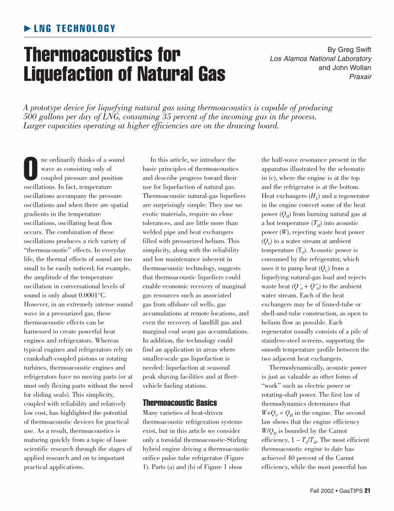
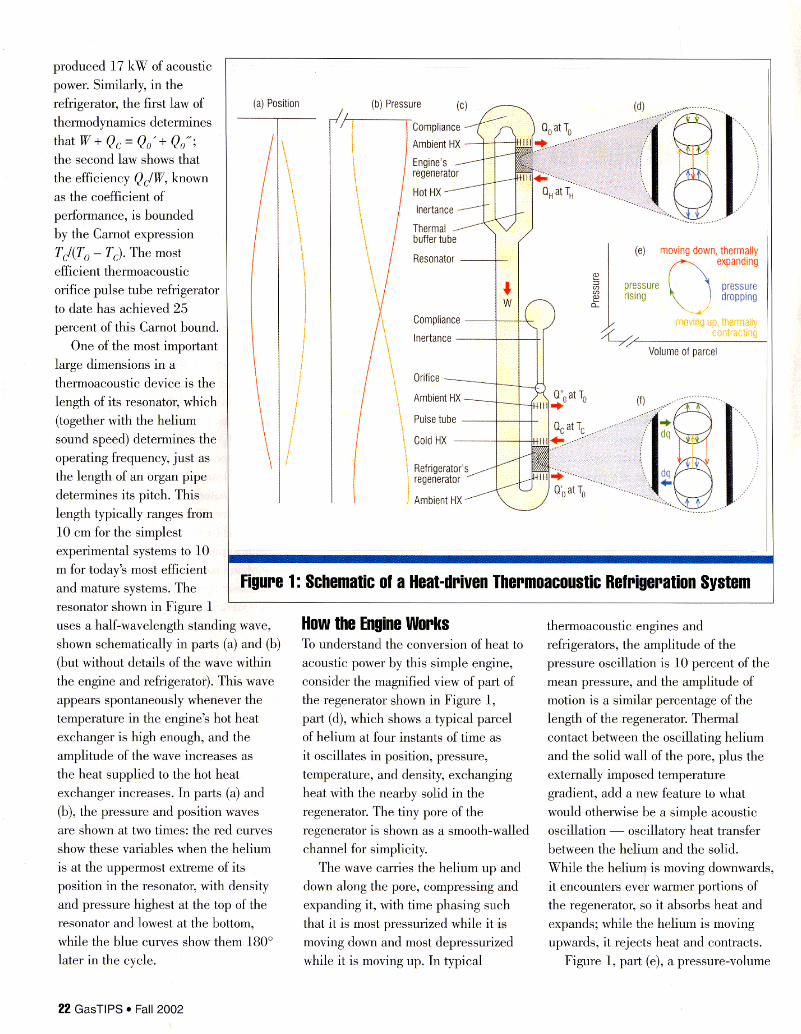
Thermoacoustic BasicsMany varieties of heat-driventhermoacoustic refrigeration systemsexist, but in this article we consideronly a toroidal thermoacoustic-Stirlinghybrid engine driving a thermoacousticorifice pulse tube refrigerator (Figure1). Parts (a) and (b) of Figure 1 show
the half-wave resonance present in theapparatus illustrated by the schematicin (c), where the engine is at the topand the refrigerator is at the bottom.Heat exchangers (HX) and a regeneratorin the engine convert some of the heatpower (QH) from burning natural gas ata hot temperature (TH) into acousticpower (W), rejecting waste heat power(Q0) to a water stream at ambienttemperature (T0). Acoustic power isconsumed by the refrigerator, whichuses it to pump heat (QC) from aliquefying natural-gas load and rejectswaste heat (Q´0 + Q˝0) to the ambientwater stream. Each of the heatexchangers may be of finned-tube orshell-and-tube construction, as open tohelium flow as possible. Eachregenerator usually consists of a pile ofstainless-steel screens, supporting thesmooth temperature profile between thetwo adjacent heat exchangers.
Thermodynamically, acoustic poweris just as valuable as other forms of“work” such as electric power orrotating-shaft power. The first law ofthermodynamics determines thatW+Q0 = QH in the engine. The secondlaw shows that the engine efficiencyW/QH is bounded by the Carnotefficiency, 1 – T0/TH. The most efficientthermoacoustic engine to date hasachieved 40 percent of the Carnotefficiency, while the most powerful has
R L N G T E C H N O L O G Y
Fall 2002 • GasTIPS 21
By Greg SwiftLos Alamos National Laboratory
and John WollanPraxair
Thermoacoustics forLiquefaction of Natural GasA prototype device for liquefying natural gas using thermoacoustics is capable of producing500 gallons per day of LNG, consuming 35 percent of the incoming gas in the process.Larger capacities operating at higher efficiencies are on the drawing board.
produced 17 kW of acoustic power. Similarly, in the refrigerator, the first law of thermodynamics determines that W + Qc = Qo'+ Q / ; the second law shows that the efficiency Q&W,' known as the coefficient of performance, is bounded by the Carnot expression TJ(T, - Tc). The most efficient thermoacoustic orifice pulse tube refrigerator to date has achieved 25 percent of this Carnot bound.
One of the most important large dimensions in a thermoacoustic device is the length of its resonator, which (together with the helium sound speed) determines the operating frequency, just as the length of an organ pipe determines its pitch. This length typically ranges from 10 cm for the simplest experimental systems to 10 m for today's most efficient and mature systems. The resonator shown in Figure 1
\ . . . . . . . . . II
~~ . . . . . . , . . . . . . . . . . . . . . . . . . . . .
(a) Position 1
I :
I I
regenerator
/ Resonator ,-i
. ,
I
'-' moving down, thermaUy A expandim
l . . ....... . . . . . . . . . . . . . . . . . . . . . . . . . . . . . . . . . . . . . . . . . . . . . . . . . . . . . . . . . . . . . . . . . . . . . . . . . . . .
Figure 1: Schematic of a Heat-driven Thermoacoustic Refrigeration System
uses a half-wavelength standing wave, shown schematically in parts (a) and (b) (but without details of the wave within the engine and refrigerator). This wave appears spontaneously whenever the temperature in the engine's hot heat exchanger is high enough, and the amplitude of the wave increases as the heat supplied to the hot heat exchanger increases. In parts (a) and (b), the pressure and position waves are shown at two times: the red curves show these variables when the helium is at the uppermost extreme of its position in the resonator, with density and pressure highest at the top of the resonator and lowest at the bottom, while the blue curves show them 180" later in the cycle.
How the Engine M r k s To understand the conversion of heat to
thermoacoustic engines and refrigerators, the amplitude of the
acoustic power by this simple engine, consider the magnified view of part of the regenerator shown in Figure 1, part (d), which shows a typical parcel of helium at four instants of time as it oscillates in position, pressure, temperature, and density, exchanging heat with the nearby solid in the regenerator. The tiny pore of the regenerator is shown as a smooth-walled channel for simplicity.
The wave carries the helium up and down along the pore, compressing and expanding it, with time phasing such that it is most pressurized while it is moving down and most depressurized while it is moving up. In typical
pressure oscillation is 10 percent of the mean pressure, and the amplitude of motion is a similar percentage of the length of the regenerator. Thermal contact between the oscillating helium and the solid wall of the pore, plus the externally imposed temperature gradient, add a new feature to what would otherwise be a simple acoustic oscillation - oscillatory heat transfer between the helium and the solid. While the heliuq is moving downwards, it encounters evdr warmer portions of the regenerator, so it absorbs heat and expands; while the helium is moving upwards, it rejects heat and contracts.
Figure 1, part (e), a pressure-volume
22 GasTlPS Fall 2002
( p–V ) diagram for the parcel of heliumillustrated in part (d), shows that thehelium does net work (∫ p dV) on itssurroundings because expansion takesduring the high-pressure time of thecycle and the contraction during thelow-pressure time. This processdepends on the correct time phasingbetween motion and pressure, which ismaintained by inertial and compressiveeffects in the ductwork near theregenerator. The net work that thehelium does on its surroundings isproduced at the resonance frequency.Thus, the parcel of helium shown in (d),and all others like it within theregenerator, deliver acoustic power tothe wave, while the wave sets thefrequency of the power production.
Each parcel of helium also depositsa little heat (not shown in Figure 1) atone location in the regenerator whilethe pressure is rising and the parcel isrelatively stationary near the upperextent of its motion. It absorbs that heatnear the lower extreme of its motion, ata warmer location in the regenerator,when the pressure is falling. Withrespect to heat, all parcels act likemembers of a bucket brigade, with theoverall effect being absorption of heat atthe hot heat exchanger and rejection ofheat at the ambient heat exchanger.
Pore SizeThe pore size in the regeneratordetermines the nature of the thermalcontact between the regenerator solidheat capacity and the moving helium.Good thermal contact is needed toaccomplish the cycle shown inFigure 1, because the temperature ofthe helium should match the local solidtemperature while the helium moves.Analysis shows that a spacing betweenplates of a fraction of a thermalpenetration depthd �K = √ K/πf�cp isbest, where K is the thermalconductivity of the helium, � is its
density, cp is its isobaric specific heatper unit mass, and f is the frequency ofthe acoustic oscillation; �K is roughlythe distance heat can diffuse throughthe helium during a time 1/πf. Intoday’s thermoacoustic systems, �K istypically a fraction of a millimeter.(Pores too tight impose too muchviscous drag on the helium.)
How the Refrigerator WorksThe basic principle of operation of thethermoacoustic orifice pulse tuberefrigerator is very similar to that of thethermoacoustic engine. A magnifiedview of part of the refrigerator’sregenerator in Figure 1, part (f),illustrates one typical parcel of heliumas it oscillates in position, pressure,temperature, and density, exchangingheat (dq) with the nearby solid in theregenerator, moving that heat up thetemperature gradient. As the heliumoscillates along the refrigerator’sregenerator, it experiences changes inpressure. At the lower extreme of itsmotion, the typical parcel of heliumrejects heat (dq) to the regenerator,because the pressure rises while thehelium is relatively stationary at thatlocation. Similarly, at the upper extremeof its motion, it absorbs heat (dq) fromthe regenerator, because the pressurerises while it is relatively stationarythere. Thus, the parcel of helium movesa little heat along the regenerator, upthe temperature gradient, during eachcycle of the acoustic wave. All the otherparcels in the regenerator behavesimilarly, so that the overall effect,again like in a bucket brigade, is thenet transport of heat from the coldheat exchanger to the ambientheat exchanger.
The helium also consumes acousticpower from the wave (not shown inFigure 1), because the thermalexpansion of the helium, attending itsdownward motion, occurs during the
low pressure time of the acoustic wave,and the thermal contraction, attendingits upward motion, occurs during thehigh pressure time. The resultingacoustic power absorbed by the heliumis supplied by the thermoacousticengine, transmitted to the refrigeratorthrough the wave in the resonator.
Development HistoryHeat driven acoustic oscillators havebeen known for over a century — theearliest and simplest was discoveredaccidentally by European glassblowers.But an accurate theory applicable tothermoacoustic phenomena was notdeveloped until the 1970s, through theefforts of Nicholas Rott and coworkersat ETH-Zurich. Rott’s theory is basedon a low-amplitude linearization of theNavier-Stokes, continuity, and energyequations, with sinusoidal oscillationsof all variables.
In the early 1980s, the thermal-physics team at Los Alamos, supportedby BES in DOE’s Office of Science,was frustrated by the large numberof precision moving parts requiredfor their experiments on thethermodynamic behavior of near-criticalliquids in heat engines. While lookingfor simpler engine designs, they readthe publications of Peter Ceperley atGeorge Mason University, who hadrealized that the timing betweenpressure changes and motion inStirling engines is the same as in atraveling sound wave (Ceperley, 1979).Inspired by his insight, the Los Alamosresearchers began consideringacoustic technology to eliminatemoving parts. Eventually, they broughttogether a thermodynamic point of view,acoustic techniques, explicit heatexchangers, and Rott’s theory,producing the first powerfulthermoacoustic engines and the firstthermoacoustic refrigerators.Fundamental research on
Fall 2002 • GasTIPS 23
thermoacoustics has grown eversince, at Los Alamos and throughoutthe world.
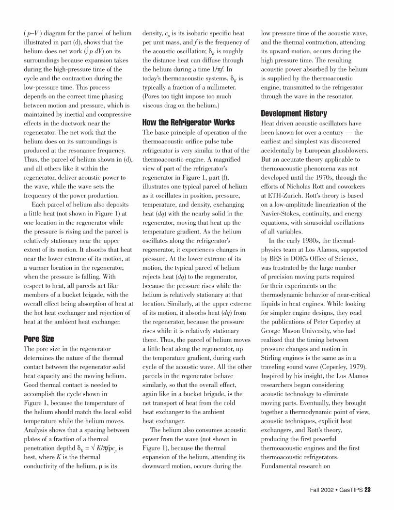
In the late 1980s, a partnershipbetween the Los Alamos team and RayRadebaugh at the National Bureau ofStandards (now National Institute ofStandards and Technology) in Bouldercombined a thermoacoustic engine withan orifice pulse tube refrigerator tocreate the first cryogenic refrigeratorwith no moving parts (Figure 2). Thisdevice was dubbed the “Coolahoop”because the bent brass portion of thehalf-wavelength acoustic resonator(extending upward in Figure 2)resembled a hulahoop (Radebaugh,et al., 1991). In the photo, the pulsetube refrigerator is the silver-colored“U” at bottom center, while the twothermoacoustic engines are under thebulky white insulation to the right andleft of the refrigerator.
Even though this early system hadonly 5 W of cooling power at 120Kelvin, Radebaugh believed from theoutset that the best application for thisheat-driven refrigerator would be
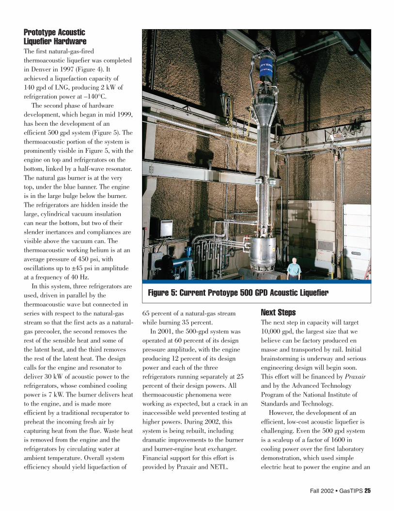
liquefaction ofnatural gas, usingcombustion of gasas the heat source.A typical moderngas liquefactionplant costs abillion dollars,liquefies 104
m3/day, and hassubstantialoperating andmaintenance costs.The need forrelatively small, reliable, inexpensiveliquefaction equipment seemedclear and an “acoustic liquefier”seemed to fit the need perfectly. Thegoal of an acoustic liquefier with acapacity of 10,000 gallons per day (gpd)followed, eventually includingeconomic analysis for arrays of suchliquefiers on floating LNG production/storage vessels and oil/gas separationvessels (van Wijngaarden, 1999;Figure 3).
Cryenco, a small manufacturingcompany in Denver, began working on
this technology in 1994. The followingyear, DOE’s Office of Fossil Energy(through NETL) began supporting LosAlamos team’s partnership withCryenco. Hardware developmentcontinued in Denver through manytransitions, most recently as Praxairacquired the project. While working onthe Denver development, the LosAlamos researchers have continuedresearch on fundamentals, increasingengine efficiency and bringingthermoacoustic improvements to orificepulse tube refrigerators.
24 GasTIPS • Fall 2002
Figure 3: Illustrations of an Acoustic Liquefierand Offshore Applications
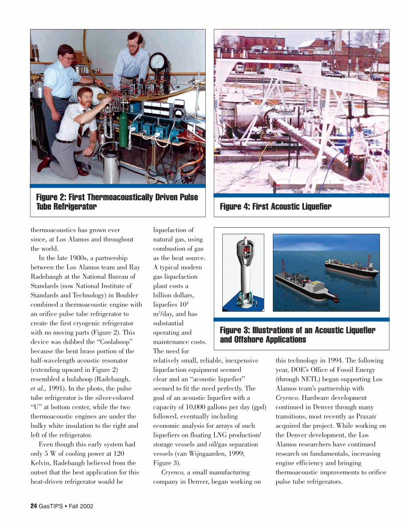
Figure 2: First Thermoacoustically Driven PulseTube Refrigerator Figure 4: First Acoustic Liquefier
Prototype AcousticLiquefier HardwareThe first natural-gas-firedthermoacoustic liquefier was completedin Denver in 1997 (Figure 4). Itachieved a liquefaction capacity of140 gpd of LNG, producing 2 kW ofrefrigeration power at –140°C.
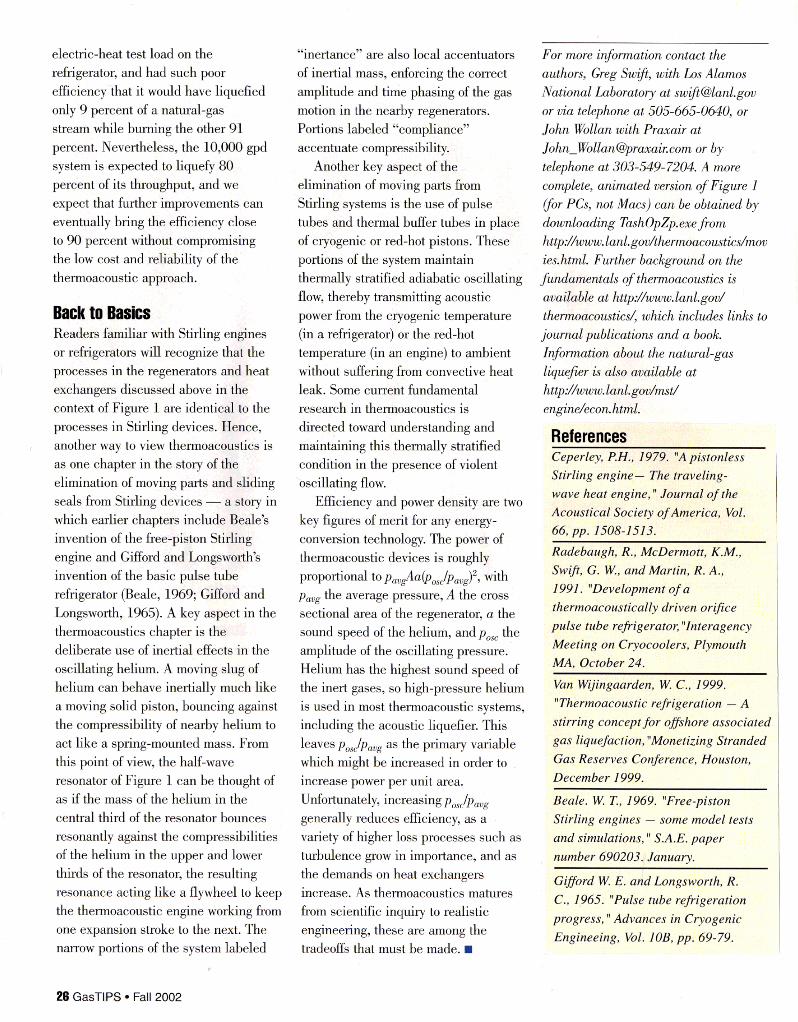
The second phase of hardwaredevelopment, which began in mid 1999,has been the development of anefficient 500 gpd system (Figure 5). Thethermoacoustic portion of the system isprominently visible in Figure 5, with theengine on top and refrigerators on thebottom, linked by a half-wave resonator.The natural gas burner is at the verytop, under the blue banner. The engineis in the large bulge below the burner.The refrigerators are hidden inside thelarge, cylindrical vacuum insulationcan near the bottom, but two of theirslender inertances and compliances arevisible above the vacuum can. Thethermoacoustic working helium is at anaverage pressure of 450 psi, withoscillations up to ±45 psi in amplitudeat a frequency of 40 Hz.
In this system, three refrigerators areused, driven in parallel by thethermoacoustic wave but connected inseries with respect to the natural-gasstream so that the first acts as a natural-gas precooler, the second removes therest of the sensible heat and some ofthe latent heat, and the third removesthe rest of the latent heat. The designcalls for the engine and resonator todeliver 30 kW of acoustic power to therefrigerators, whose combined coolingpower is 7 kW. The burner delivers heatto the engine, and is made moreefficient by a traditional recuperator topreheat the incoming fresh air bycapturing heat from the flue. Waste heatis removed from the engine and therefrigerators by circulating water atambient temperature. Overall systemefficiency should yield liquefaction of
65 percent of a natural-gas streamwhile burning 35 percent.
In 2001, the 500-gpd system wasoperated at 60 percent of its designpressure amplitude, with the engineproducing 12 percent of its designpower and each of the threerefrigerators running separately at 25percent of their design powers. Allthermoacoustic phenomena wereworking as expected, but a crack in aninaccessible weld prevented testing athigher powers. During 2002, thissystem is being rebuilt, includingdramatic improvements to the burnerand burner-engine heat exchanger.Financial support for this effort isprovided by Praxair and NETL.
Next StepsThe next step in capacity will target10,000 gpd, the largest size that webelieve can be factory produced enmasse and transported by rail. Initialbrainstorming is underway and seriousengineering design will begin soon.This effort will be financed by Praxairand by the Advanced TechnologyProgram of the National Institute ofStandards and Technology.
However, the development of anefficient, low-cost acoustic liquefier ischallenging. Even the 500 gpd systemis a scaleup of a factor of 1600 incooling power over the first laboratorydemonstration, which used simpleelectric heat to power the engine and an
Fall 2002 • GasTIPS 25
Figure 5: Current Protoype 500 GPD Acoustic Liquefier
electric-heat test load on the refrigerator, and had such poor efficiency that it would have liquefied only 9 percent of a natural-gas stream while burning the other 91 percent. Nevertheless, the 10,OOO gpd system is expected to liquefy 80 percent of its throughput, and we expect that further improvements can eventually bring the efficiency close to 90 percent without compromising the low cost and reliability of the thermoacoustic approach.
Back to Basics Readers familiar with Stirling engines or refrigerators will recognize that the processes in the regenerators and heat exchangers discussed above in the context of Figure 1 are identical to the processes in Stirling devices. Hence, another way to view thermoacoustics is as one chapter in the story of the elimination of moving parts and sliding seals fiom Stirling devices - a story in which earlier chapters include Beale’s invention of the free-piston Stirling engine and Gifford and Longsworth‘s invention of the basic pulse tube refrigerator (Beale, 1969; Gifford and Longsworth, 1965). A key aspect in the thermoacoustics chapter is the deliberate use of inertial effects in the oscillating helium. A moving slug of helium can behave inertially much like a moving solid piston, bouncing against the compressibility of nearby helium to act like a spring-mounted mass. From this point of view, the half-wave resonator of Figure 1 can be thought of as if the mass of the helium in the central third of the resonator bounces resonantly against the compressibilities of the helium in the upper and lower thirds of the resonator, the resulting resonance acting like a flywheel to keep the thermoacoustic engine working from one expansion stroke to the next. The narrow portions of the system labeled
“inertance” are also local accentuators of inertial mass, enforcing the correct amplitude and time phasing of the gas motion in the nearby regenerators. Portions labeled “compliance” accentuate compressibility.
Another key aspect of the elimination of moving parts from Stirling systems is the use of pulse tubes and thermal buffer tubes in place of cryogenic or red-hot pistons. These portions of the system maintain thermally stratified adiabatic oscillating flow, thereby transmitting acoustic power from the cryogenic temperature (in a refrigerator) or the red-hot temperature (in an engine) to ambient without suffering from convective heat leak. Some current fundamental research in thermoacoustics is directed toward understanding and maintaining this thermally stratified condition in the presence of violent oscillating flow.
key figures of merit for any energy- conversion technology. The power of thermoacoustic devices is roughly proportional to pav$la(vosJpavg)2, with pavg the average pressure, A the cross sectional area of the regenerator, a the sound speed of the helium, and post the amplitude of the oscillating pressure. Helium has the highest sound speed of the inert gases, so high-pressure helium is used in most thermoacoustic systems, including the acoustic liquefier. This leaves p,Jpmg as the primary variable which might be increased in order to increase power per unit area. Unfortunately, increasing posJpavg generally reduces efficiency, as a variety of higher loss processes such as turbulence grow in importance, and as the demands on heat exchangers increase. As thermoacoustics matures from scientific inquiry to realistic engineering, these are among the tradeoffs that must be made. rn
Efficiency and power density are two
For more information contact the authors, Greg Sw$, with Los Alamos National Laboratory at swi@[email protected] or via telephone at 505-665-0640, or John Wollan with Praxair at [email protected] or by telephone at 303-549-7204 A more complete, animated version of Figure I Vor PCs, not Macs) can be obtained by downloading TashOpZp.exe from httpd/www. lanl.gov/thennoacoustics/mov ies.html. Further background on the fundamentals of thennoacoustics is available at http:,%uww.lanl.gov/ thermoacousti& which includes l i d s to journal publications and a book. InJonnation about the natural-gas liquefir is also available at httpd/iuunu.lanl.gov/mstJ engidecon. html.
References Ceperley, P.H., 1979. ”A pistonless Stirling engine- The traveling- wave heat engine,“ Journal of the Acoustical Society of America, Vol. 66, p p . 1508-1513. Radebaugh, R., McDermott, K.M., Swifi, G. W., andMartin, R. A., 1991. “Development of a thermoacoustically driven orifice pulse tube refrigerator, “Interagency Meeting on Cryocoolers, Plymouth MA, October 24. Van Wijingaarden, W. C., 1999. “Therrnoacoustic refrigeration - A stirring concept for offshore associated gas liquefaction, “Monetizing Stranded Gas Reserves Conference, Houston, December 1999.
Beale. W. T., 1969. “Free-piston StirlinP P n P i n P s - w m p m n h l t m t c
and simulations,” S.A.E. paper number 690203.< January.
Gifford W. E. and Longsworth, R. C., 1965. “Pulse tube refrigeration progress, I’ Advances in Cryogenic