Embed Size (px)
Citation preview
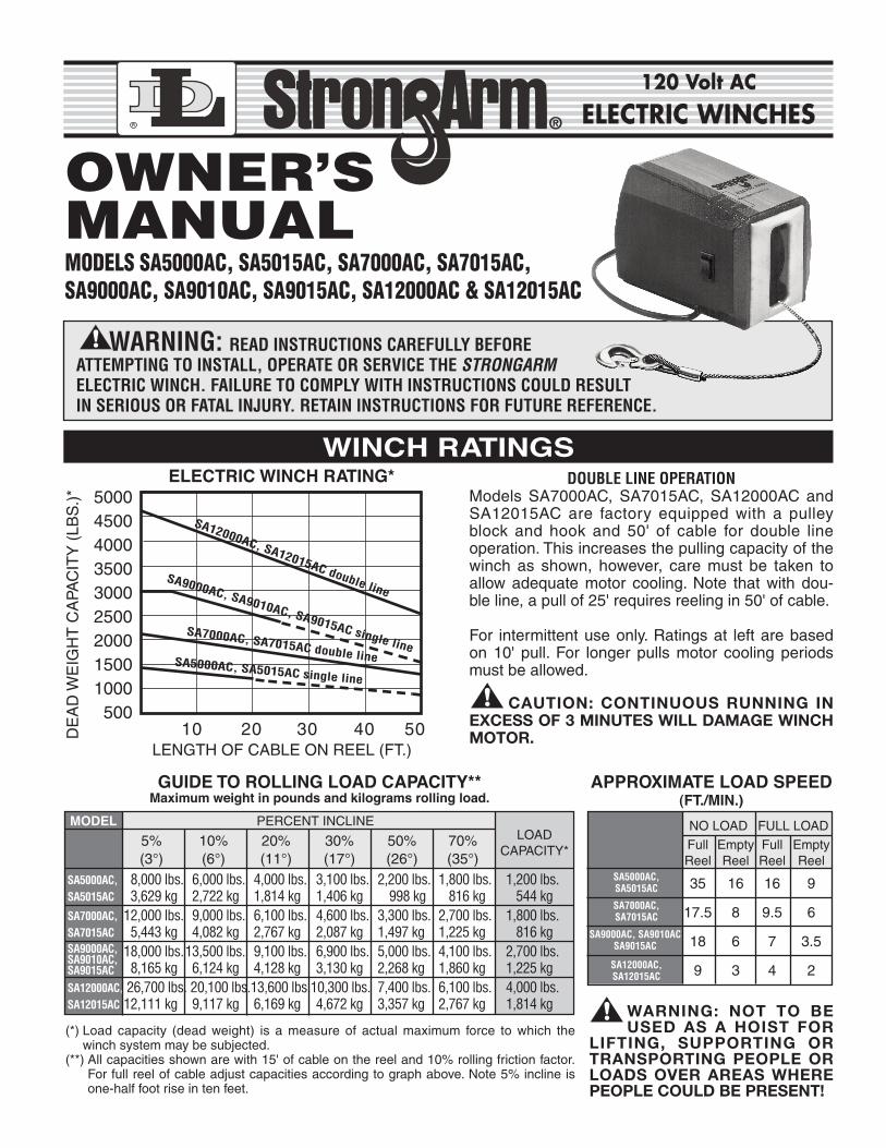
ELECTRIC WINCH RATING*
5% 10% 20% 30% 50% 70%(3°) (6°) (11°) (17°) (26°) (35°)
SA5000AC, 8,000 lbs. 6,000 lbs. 4,000 lbs. 3,100 lbs. 2,200 lbs. 1,800 lbs. 1,200 lbs.SA5015AC 3,629 kg 2,722 kg 1,814 kg 1,406 kg 998 kg ,816 kg ,544 kgSA7000AC, 12,000 lbs. 9,000 lbs. 6,100 lbs. 4,600 lbs. 3,300 lbs. 2,700 lbs. 1,800 lbs.SA7015AC 5,443 kg 4,082 kg 2,767 kg 2,087 kg 1,497 kg 1,225 kg ,816 kg
18,000 lbs.13,500 lbs. 9,100 lbs. 6,900 lbs. 5,000 lbs. 4,100 lbs. 2,700 lbs.8,165 kg 6,124 kg 4,128 kg 3,130 kg 2,268 kg 1,860 kg 1,225 kg
SA12000AC, 26,700 lbs. 20,100 lbs.13,600 lbs.10,300 lbs. 7,400 lbs. 6,100 lbs. 4,000 lbs.SA12015AC 12,111 kg 9,117 kg 6,169 kg 4,672 kg 3,357 kg 2,767 kg 1,814 kg
R
120 Volt AC
ELECTRIC WINCHES
DOUBLE LINE OPERATIONModels SA7000AC, SA7015AC, SA12000AC andSA12015AC are factory equipped with a pulleyblock and hook and 50' of cable for double lineoperation. This increases the pulling capacity of thewinch as shown, however, care must be taken toallow adequate motor cooling. Note that with dou-ble line, a pull of 25' requires reeling in 50' of cable.
For intermittent use only. Ratings at left are basedon 10' pull. For longer pulls motor cooling periodsmust be allowed.
caution: continuous running inexcess of 3 minutes Will damage Winchmotor.
GUIDE TO ROLLING LOAD CAPACITY**Maximum weight in pounds and kilograms rolling load.
APPROXIMATE LOAD SPEED(FT./MIN.)
MODEL PERCENT INCLINELOAD
CAPACITY*
(*) Load capacity (dead weight) is a measure of actual maximum force to which thewinch system may be subjected.
(**) All capacities shown are with 15' of cable on the reel and 10% rolling friction factor.For full reel of cable adjust capacities according to graph above. Note 5% incline isone-half foot rise in ten feet.
WINCH RATINGS
OWNER’S MANUAL
500045004000 350030002500200015001000500
DE
AD
WE
IGH
T C
APA
CIT
Y (
LBS
.)*
LENGTH OF CABLE ON REEL (FT.)10 20 30 40 50
SA9000AC, SA9010AC, SA9015AC single line
SA12000AC, SA12015AC double line
SA7000AC, SA7015AC double lineSA5000AC, SA5015AC single line
Warning: not to beused as a hoist for
lifting, supporting ortransporting people orloads over areas Wherepeople could be present!
NO LOAD FULL LOADFull Empty Full EmptyReel Reel Reel Reel
35 16 16 9
17.5 8 9.5 6
18 6 7 3.5
9 3 4 2
WARNING: READ INSTRUCTIONS CAREFULLY BEFOREATTEMPTING TO INSTALL, OPERATE OR SERVICE THE STRONGARM ELECTRIC WINCH. FAILURE TO COMPLY WITH INSTRUCTIONS COULD RESULTIN SERIOUS OR FATAL INJURY. RETAIN INSTRUCTIONS FOR FUTURE REFERENCE.
MODELS SA5000AC, SA5015AC, SA7000AC, SA7015AC,SA9000AC, SA9010AC, SA9015AC, SA12000AC & SA12015AC
SA9000AC,SA9010AC,SA9015AC
SA5000AC,SA5015AC
SA7000AC,SA7015AC
SA12000AC,SA12015AC
SA9000AC, SA9010ACSA9015AC
Warning: failure to read andfolloW instructions beloW couldresult in serious or fatal injury.
Warning: not to be used as a hoistfor lifting, supporting, ortransporting people or loads overareas Where people could bepresent.
This winch is not designed for movement ofhuman beings. Do not use for scaffolding,elevators, or any other application in whichpersons could be positioned on or under theload at any time. Do not use as an overheadhoist.This electric winch should be respected aspower equipment. High forces are created whenusing a winch, creating potential safety hazards.Never allow children or anyone who is notfamiliar with the operation of the winch to use it.Never exceed rated winch capacity.Dangerously high forces can be created if theload being moved is too large or is allowed toget in a bind, etc. Note that installing longer thannormal cable results in increased load on winch.If overloaded, this winch has power enough tobreak the cable.Inspect the winch cable often and replace at thefirst sign of damage. Never exceed the winchcapacity. When cable breaks under tension, ittends to whip toward the winch area. It isrecommended that a blanket or rug be placedover the cable during winching operations tominimize this whipping action in case of cablebreakage.Never apply load to winch with cable fullyextended. Keep at least three turns of cable onthe reel.
IMPORTANT SAFETY INFORMATION
Keep the winching area free of all unnecessarypersonnel. Never stand between load andwinch.When winching operation has been completed,do not depend on the winch to support theload. Always secure the load properly. Use tiedown straps or chains.The auxiliary handle is provided for emergencyuse only. Never use the auxiliary handle as anassist to the motor when the motor is running.Always remove the auxiliary handle when it isnot in use. Do not operate the winch motor withthe handle installed.Keep hands and fingers clear of the drum andcable area of the winch when operating. Do notattempt to guide the cable by hand as itrewinds on the drum.Special care should be taken with 120-volt ACwinch, as with any other 120-volt tools. Somewinch models are equipped with a ground faultcircuit interrupter in the power cord. Read andfollow instructions on the back of the GFCI.The winch should be used only with a threepronged grounded outlet. Do not remove thegrounding prong on the power cord for anyreason. Do not operate the unit in the rain orwhen it is wet and never operate the winchwhile standing in water.The winch must be securely attached to astructural member or frame that is capable ofsustaining loads in excess of the winchcapacity.Periodically check the power cord for wear orfrays which could cause electrical shorts orshocks.
MOUNTING INSTRUCTIONS
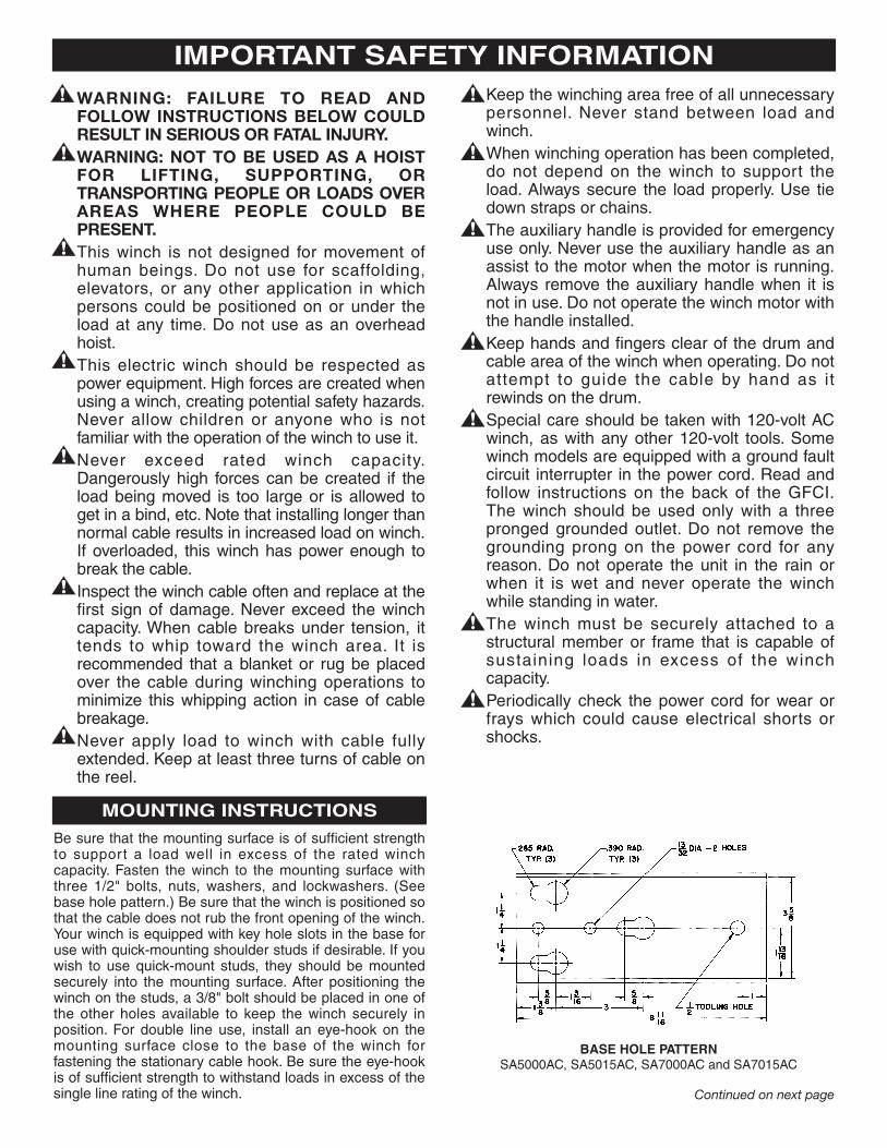
Be sure that the mounting surface is of sufficient strengthto support a load well in excess of the rated winchcapacity. Fasten the winch to the mounting surface withthree 1/2" bolts, nuts, washers, and lockwashers. (Seebase hole pattern.) Be sure that the winch is positioned sothat the cable does not rub the front opening of the winch.Your winch is equipped with key hole slots in the base foruse with quick-mounting shoulder studs if desirable. If youwish to use quick-mount studs, they should be mountedsecurely into the mounting surface. After positioning thewinch on the studs, a 3/8" bolt should be placed in one ofthe other holes available to keep the winch securely inposition. For double line use, install an eye-hook on themounting surface close to the base of the winch forfastening the stationary cable hook. Be sure the eye-hookis of sufficient strength to withstand loads in excess of thesingle line rating of the winch.
BASE HOLE PATTERNSA5000AC, SA5015AC, SA7000AC and SA7015AC
Continued on next page
MOUNTING INSTRUCTIONS continued
OPERATING INSTRUCTIONS
All models can be powered in or out. Allowing the switchto return to the off position will automatically stop thewinch and hold the load.For units with the hand held Dynamic Brake RemoteControl, press the “In/Out” switch to the desired directionand then push and hold the “Run” switch to power thewinch.
CAUTION: Do not change cable direction while themotor is running. Changing directions prior toreleasing the “Run” switch may result in winch ormotor damage.
It is recommended that whenever the winch is not beingused that it be unplugged from the power supply. Thebridge is subject to damage caused by electrical storms orvoltage surges if the winch is left plugged in when not inuse.NOTE: Some models are supplied with a GFCI cord set.To ensure protection against electrical shock, test theGFCI before each use. See back of GFCI for testprocedure.NOTE: It is normal for smoke to be produced during theinitial power down use.
Warning: because the Winch is noteQuipped With circuit breaKer overloadprotection, particular care should betaKen not to create an overload. payattention to the sound of the Winch andthe load being pulled. maKe certain thatthe cable tension does not risesuddenly because of a bind in the load.
caution: the electric motor is designed forintermittent service only. extended use withoutcooling off periods will cause overheating resulting in motor damage. maximum continuousrun time is three minutes.
Warning: never alloW children, oranyone Who is not familiar With theoperation of the Winch, to use it.
AUXILIARY HANDLE
1. An emergency crank handle is provided for use in theevent of a power failure. Remove the electrical powerfrom the winch.
2. Remove the plastic plug from the side of the winchhousing and insert the handle so that it completelyengages with the drive shaft. The handle can becranked in either direction.
WARNING: NEVER OPERATE THE WINCHELECTRICALLY WITH THE EMERGENCY HANDLEIN POSITION.
3. Always remove the handle from the winch after useand replace the plastic plug.
WINCH MAINTENANCE
For long life and trouble-free operation your winch shouldperiodically be inspected for any required maintenance.This should be done at least once annually and morefrequently in adverse conditions such as salt water areasor areas of extreme dust and dirt.1. Carefully inspect the winch cable for any kinks, frays
or abnormal stiffness and replace at the first sign of this kind of damage. Periodic lubrication with a light oilwill improve the life of the cable. In order to replace thewinch cable, it is necessary to remove the four covermounting bolts. Be sure that the power is disconnectedfrom the housing and lift the housing off of the winch by gently stretching it open near the lower front corner.Rotate the winch reel so that you have access to therope clamp. Remove the old cable and replace it with anew cable of the same size. Be sure that the cablepasses under both sides of the rope clamp and that the clamp is tightened securely.
2. With the cover removed as described above, inspect theentire gear train and all drive shafts for any significant wearor loose bearing fits. Grease all of the gears on the inside of
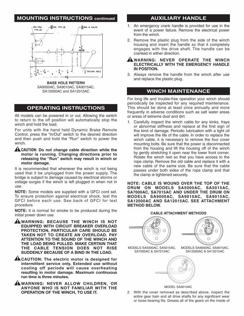
NOTE: CABLE IS WOUND OVER THE TOP OF THEDRUM ON MODELS SA5000AC, SA5015AC,SA7000AC, SA7015AC AND UNDER THE DRUM ONMODELS SA9000AC, SA9010AC, SA9015AC,SA12000AC AND SA12015AC. SEE ATTACHMENTMETHOD BELOW.
BASE HOLE PATTERNSA9000AC, SA9010AC, SA9015AC,
SA12000AC and SA12015AC
CABLE ATTACHMENT METHODS
MODELS SA5000AC, SA5015AC,SA7000AC & SA7015AC
MODELS SA9000AC, SA9015AC,SA12000AC & SA12015AC
MODEL SA9010AC
SYMPTOM POSSIBLE CAUSE(S) CORRECTIVE ACTION
Safety hook spreads. 1. Point loading of hook. 1. Replace hook.2. Load exceeds rated capacity of unit. 2. Lighten load, reduce %
of incline or reduce load friction.
Cable snaps. 1. Improperly maintained cable. 1. See “Maintenance”.2. Overloading. 2. Reduce load.
Cable miswrap Loose cable being wound onto drum. Keep tension on cable at all times.and/or crushing.
Load creeps when power is OFF. 1. Roller clutch, not engaging. 1. Replace.2. Overloading. 2. Reduce load.
Damaged level wind spring Loose cable. Keep tension on cable at all times.Models SA9000AC, SA9010AC, SA9015AC,SA12000AC & SA12015AC.
Winch motor runs hot. In operation too long. Let motor cool for at least 20 minutes.(See Winch Rating Section).
Winch motor fails to run. Electrical. Check the following: power supply, wiring,control switch, male/female connectionsand motor.
Winch pops circuit breaker Damaged bridge. Replace bridge and keep winch unpluggedimmediately when plugged in. when not in use.
GFCI interrupts circuit or will Possible short or electrical leakage. Correct electrical problem and reset GFCI.not reset.
GFCI does not test properly. Faulty GFCI. Replace GFCI.
Smokes. Normal on initial power down use. None.
TROUBLESHOOTING CHART
the winch base and apply a drop of oil on all of thebearings in the base. Also, place a drop of oil on the rollerclutch. Do not over lubricate these areas and do not usegrease in the roller clutch. The brake pads and brake discmust be kept clean and oil free.
3. Check the operation of the roller clutch. Carefully rotatethe brake disc and observe the motor shaft. When thedisc is turned clockwise the motor shaft should turn with
it. When the disc is turned counterclockwise the motorshaft should not turn. Also, check all nuts, bolts, retainingrings, etc., to be sure that they are tight and secure.
4. If a pully block and hook is used, check assembly to besure that the pulley rotates freely on the bronze pulleyspacer. Occasional greasing of these two items isrecommended.
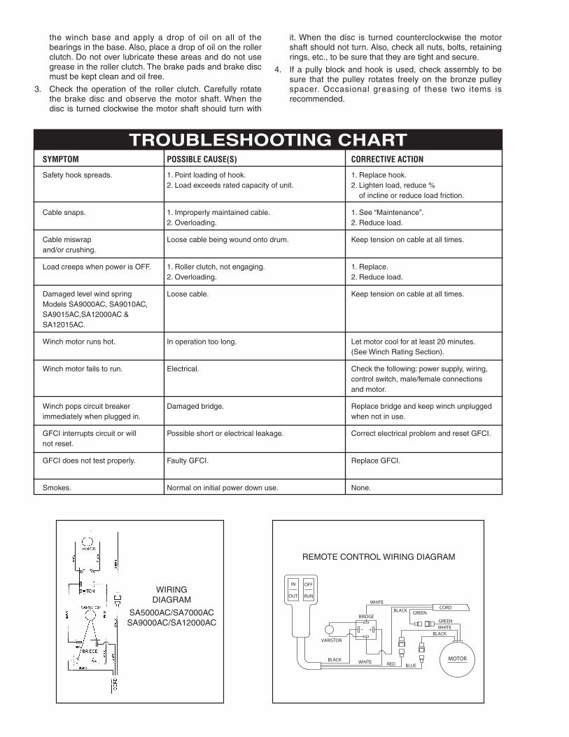
WIRINGDIAGRAM
SA5000AC/SA7000ACSA9000AC/SA12000AC
REMOTE CONTROL WIRING DIAGRAM
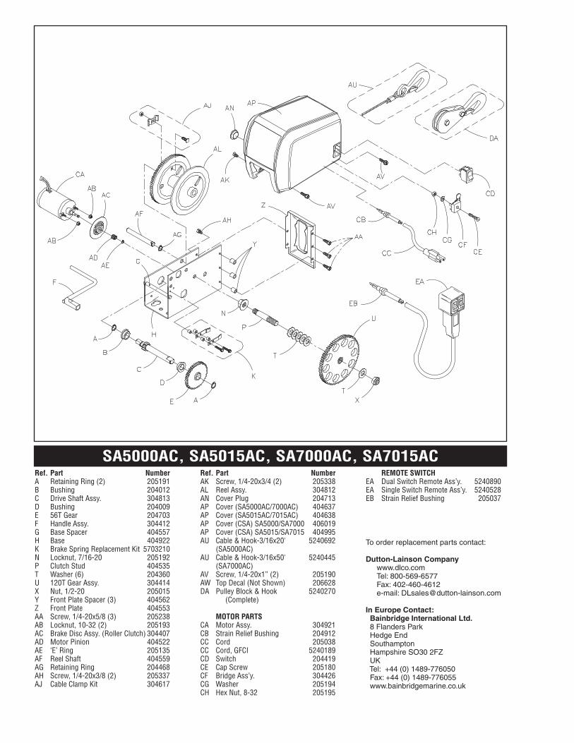
SA5000AC, SA5015AC, SA7000AC, SA7015ACRef. Part NumberA Retaining Ring (2) 205191B Bushing 204012C Drive Shaft Assy. 304813D Bushing 204009E 56T Gear 204703F Handle Assy. 304412G Base Spacer 404557H Base 404922K Brake Spring Replacement Kit 5703210N Locknut, 7/16-20 205192P Clutch Stud 404535T Washer (6) 204360U 120T Gear Assy. 304414X Nut, 1/2-20 205015Y Front Plate Spacer (3) 404562Z Front Plate 404553AA Screw, 1/4-20x5/8 (3) 205238AB Locknut, 10-32 (2) 205193AC Brake Disc Assy. (Roller Clutch) 304407AD Motor Pinion 404522AE ‘E’ Ring 205135AF Reel Shaft 404559AG Retaining Ring 204468AH Screw, 1/4-20x3/8 (2) 205337AJ Cable Clamp Kit 304617
Ref. Part NumberAK Screw, 1/4-20x3/4 (2) 205338AL Reel Assy. 304812AN Cover Plug 204713AP Cover (SA5000AC/7000AC) 404637AP Cover (SA5015AC/7015AC) 404638AP Cover (CSA) SA5000/SA7000 406019AP Cover (CSA) SA5015/SA7015 404995AU Cable & Hook-3/16x20' 5240692
(SA5000AC)AU Cable & Hook-3/16x50' 5240445
(SA7000AC)AV Screw, 1/4-20x1” (2) 205190AW Top Decal (Not Shown) 206628DA Pulley Block & Hook 5240270
(Complete)
MOTOR PARTSCA Motor Assy. 304921CB Strain Relief Bushing 204912CC Cord 205038CC Cord, GFCI 5240189CD Switch 204419CE Cap Screw 205180CF Bridge Ass’y. 304426CG Washer 205194CH Hex Nut, 8-32 205195
REMOTE SWITCHEA Dual Switch Remote Ass’y. 5240890EA Single Switch Remote Ass’y. 5240528EB Strain Relief Bushing 205037
To order replacement parts contact:
Dutton-Lainson Companywww.dlco.comTel: 800-569-6577Fax: 402-460-4612e-mail: [email protected]
In Europe Contact:Bainbridge International Ltd.8 Flanders ParkHedge EndSouthamptonHampshire SO30 2FZUKTel: +44 (0) 1489-776050Fax: +44 (0) 1489-776055www.bainbridgemarine.co.uk
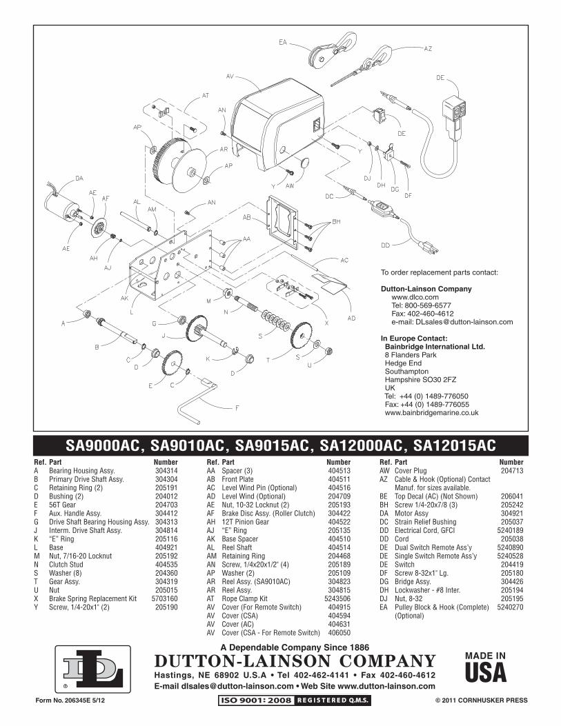
SA9000AC, SA9010AC, SA9015AC, SA12000AC, SA12015ACRef. Part NumberA Bearing Housing Assy. 304314B Primary Drive Shaft Assy. 304304C Retaining Ring (2) 205191D Bushing (2) 204012E 56T Gear 204703F Aux. Handle Assy. 304412G Drive Shaft Bearing Housing Assy. 304313J Interm. Drive Shaft Assy. 304814K “E” Ring 205116L Base 404921M Nut, 7/16-20 Locknut 205192N Clutch Stud 404535S Washer (8) 204360T Gear Assy. 304319U Nut 205015X Brake Spring Replacement Kit 5703160Y Screw, 1/4-20x1" (2) 205190
Ref. Part NumberAA Spacer (3) 404513AB Front Plate 404511AC Level Wind Pin (Optional) 404516AD Level Wind (Optional) 204709AE Nut, 10-32 Locknut (2) 205193AF Brake Disc Assy. (Roller Clutch) 304422AH 12T Pinion Gear 404522AJ “E” Ring 205135AK Base Spacer 404510AL Reel Shaft 404514AM Retaining Ring 204468AN Screw, 1/4x20x1/2" (4) 205189AP Washer (2) 205109AR Reel Assy. (SA9010AC) 304823AR Reel Assy. 304815AT Rope Clamp Kit 5243506AV Cover (For Remote Switch) 404915AV Cover (CSA) 404594AV Cover (AC) 404631AV Cover (CSA - For Remote Switch) 406050
Ref. Part NumberAW Cover Plug 204713AZ Cable & Hook (Optional) Contact
Manuf. for sizes available.BE Top Decal (AC) (Not Shown) 206041BH Screw 1/4-20x7/8 (3) 205242DA Motor Assy 304921DC Strain Relief Bushing 205037DD Electrical Cord, GFCI 5240189DD Cord 205038DE Dual Switch Remote Ass’y 5240890DE Single Switch Remote Ass’y 5240528DE Switch 204419DF Screw 8-32x1" Lg. 205180DG Bridge Assy. 304426DH Lockwasher - #8 Inter. 205194DJ Nut, 8-32 205195EA Pulley Block & Hook (Complete) 5240270
(Optional)
© 2011 CORNHUSKER PRESSForm No. 206345E 5/12
To order replacement parts contact:
Dutton-Lainson Companywww.dlco.comTel: 800-569-6577Fax: 402-460-4612e-mail: [email protected]
In Europe Contact:Bainbridge International Ltd.8 Flanders ParkHedge EndSouthamptonHampshire SO30 2FZUKTel: +44 (0) 1489-776050Fax: +44 (0) 1489-776055www.bainbridgemarine.co.uk