Embed Size (px)
Citation preview
XAPP1034 (v1.1) February 28, 2008 www.xilinx.com 1
© 2007-2008 Xilinx, Inc. All rights reserved. XILINX, the Xilinx logo, and other designated brands included herein are trademarks of Xilinx, Inc. All other trademarks are the property of their respective owners.
Abstract The application note demonstrates how to access the In-System Flash in the Spartan™-3AN FPGA after the FPGA is configured. The software application uses the Serial Peripheral Interface (XPS SPI) core to access the In-System Flash in the MicroBlaze™ processor based reference system.
This application note describes the:
• XPS SPI parameter settings and Port Connections to access the In-System Flash (ISF) memory of Spartan-3AN FPGA.
• SPI ACCESS design primitive core which is only available on Spartan-3AN FPGAs to access the ISF memory.
• Software Application that uses the Xilinx In-System Flash software library (xilisf) to communicate with the Spartan-3AN ISF Memory.
This reference system is targeted for the Xilinx Spartan-3AN Starter Kit Revision D board.
Included Systems
The reference system for the Xilinx Spartan-3AN Starter Kit Revision D board is included with this application note. The reference system is available at:
www.xilinx.com/support/documentation/application_notes/xapp1034.zip
Introduction Spartan-3AN FPGAs have In-system Flash (ISF) memory. The ISF memory array appears to the software application of a Spartan-3AN FPGA as a SPI-based serial Flash memory.
• The ISF memory is primarily designed to configure the FPGA automatically when power is applied. This is new feature in the Spartan-3AN FPGAs.
• The ISF memory is also available to the FPGA after configuration for various purposes, such as:
♦ Simple non-volatile data storage.
♦ Storage for identifier codes, serial numbers, IP addresses, etc.
♦ Storage of MicroBlaze processor code that can be copied into CPU addressable memory, such as DDR2 SDRAM.
This application note explains about how to access the SPI based ISF memory after configuration using the ISF software library. Two applications are provided - one to program with flash with an application, and a bootloader to copy this application out of the flash into DDR2 memory and execute it.
Application Note: Embedded Processing
XAPP1034 (v1.1) February 28, 2008
Reference System: Accessing Spartan-3AN In-System Flash using XPS SPIAuthor: Sundararajan Ananthakrishnan, Brian Hill
R
Hardware and Software Requirements
XAPP1034 (v1.1) February 28, 2008 www.xilinx.com 2
R
Hardware and Software Requirements
The hardware and software requirements are:
• Xilinx Spartan-3AN Starter Kit Revision D board
• Xilinx Platform USB Cable or Parallel IV Cable
• Serial null-modem cable
• Serial Communications Utility Program, such as HyperTerminal
• Xilinx Platform Studio 9.2.02i (9.2i with Service Pack 2)
• Xilinx Integrated Software Environment (ISE™) 9.2.04i (9.2i with Service Pack 4)
• Xilinx Software Development Kit 9.2.02i
Reference System Specifics
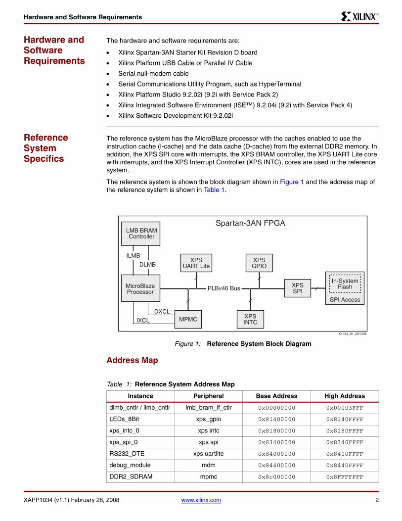
The reference system has the MicroBlaze processor with the caches enabled to use the instruction cache (I-cache) and the data cache (D-cache) from the external DDR2 memory. In addition, the XPS SPI core with interrupts, the XPS BRAM controller, the XPS UART Lite core with interrupts, and the XPS Interrupt Controller (XPS INTC), cores are used in the reference system.
The reference system is shown the block diagram shown in Figure 1 and the address map of the reference system is shown in Table 1.
Address Map
X-Ref Target - Figure 1
Figure 1: Reference System Block Diagram
Table 1: Reference System Address Map
Instance Peripheral Base Address High Address
dlmb_cntlr / ilmb_cntlr lmb_bram_if_ctlr 0x00000000 0x00003FFF
LEDs_8Bit xps_gpio 0x81400000 0x8140FFFF
xps_intc_0 xps intc 0x81800000 0x8180FFFF
xps_spi_0 xps spi 0x83400000 0x8340FFFF
RS232_DTE xps uartlite 0x84000000 0x8400FFFF
debug_module mdm 0x84400000 0x8440FFFF
DDR2_SDRAM mpmc 0x8c000000 0x8FFFFFFF
MicroBlazeProcessor
Spartan-3AN FPGALMB BRAMController
IXCL
X1034_01_021408
XPSUART Lite
SPI Access
In-SystemFlash
XPSINTC
XPSSPI
XPSGPIO
MPMCDXCL
PLBv46 Bus
ILMB
DLMB
Reference System Specifics
XAPP1034 (v1.1) February 28, 2008 www.xilinx.com 3
R
System Configuration
This Xilinx Spartan-3AN Starter Kit based reference system uses the MicroBlaze processor with the caches enabled. The XPS SPI core connects the ISF to the MicroBlaze processor though the PLBv46 bus in the reference system. The DDR2 SDRAM is used as the external memory and is configured to allow cacheline transactions from the MicroBlaze processor in the reference system. The Multi-Port Memory Controller (MPMC) is used to connect to the DDR2 SDRAM memory.
The XPS INTC core handles the interrupt signal from the XPS SPI controller.
The SPI ACCESS design primitive logic handles the transactions between the ISF Memory and the XPS SPI core.
Setting the XPS SPI core parameters
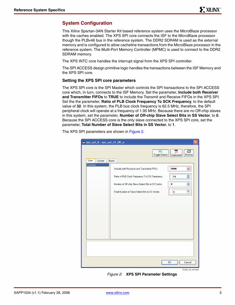
The XPS SPI core is the SPI Master which controls the SPI transactions to the SPI ACCESS core which, in turn, connects to the ISF Memory. Set the parameter, Include both Receiver and Transmitter FIFOs to TRUE to include the Transmit and Receive FIFOs in the XPS SPI. Set the the parameter, Ratio of PLB Clock Frequency To SCK Frequency, to the default value of 32. In this system, the PLB bus clock frequency is 62.5 MHz, therefore, the SPI peripheral clock will operate at a frequency of 1.95 MHz. Because there are no Off-chip slaves in this system, set the parameter, Number of Off-chip Slave Select Bits in SS Vector, to 0. Because the SPI ACCESS core is the only slave connected to the XPS SPI core, set the parameter, Total Number of Slave Select Bits in SS Vector, to 1.
The XPS SPI parameters are shown in Figure 2.X-Ref Target - Figure 2
Figure 2: XPS SPI Parameter SettingsX1034_02_021408
Reference System Specifics
XAPP1034 (v1.1) February 28, 2008 www.xilinx.com 4
R
SPI ACCESS Design Primitive
After the FPGA has been configured, the software application loaded into the FPGA can access the ISF memory using a special design primitive IP core called SPI ACCESS. All data accesses to and from the ISF memory are performed using an SPI serial protocol Mode 3 transfer mode. Neither the Spartan-3AN FPGA fabric nor the SPI ACCESS primitive includes a dedicated SPI master controller. The SPI master is provided by the XPS SPI core included in the system. The SPI ACCESS primitive IP core connects the XPS SPI to the In-System Memory array. The XPS SPI core is always the Master of each SPI transaction; the ISF memory is always the slave.
Note: See the UG333 Spartan-3AN In-System Flash User Guide for additional information on the SPI ACCESS Design Primitive core.
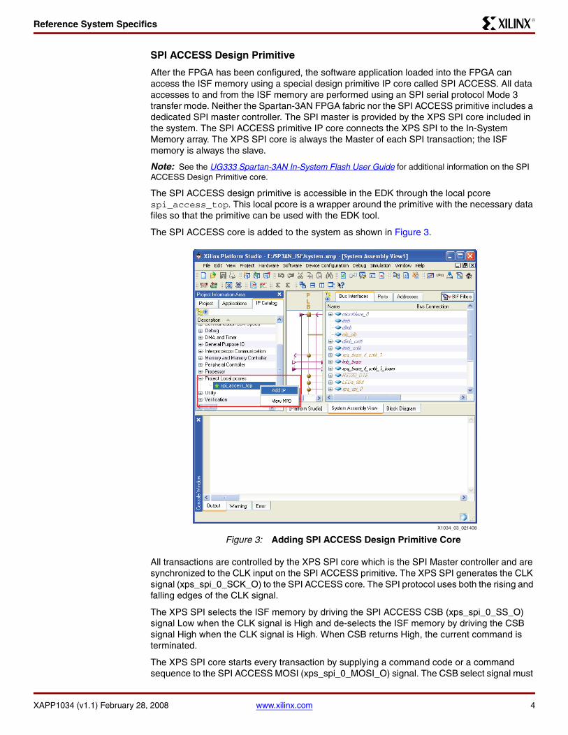
The SPI ACCESS design primitive is accessible in the EDK through the local pcore spi_access_top. This local pcore is a wrapper around the primitive with the necessary data files so that the primitive can be used with the EDK tool.
The SPI ACCESS core is added to the system as shown in Figure 3.
All transactions are controlled by the XPS SPI core which is the SPI Master controller and are synchronized to the CLK input on the SPI ACCESS primitive. The XPS SPI generates the CLK signal (xps_spi_0_SCK_O) to the SPI ACCESS core. The SPI protocol uses both the rising and falling edges of the CLK signal.
The XPS SPI selects the ISF memory by driving the SPI ACCESS CSB (xps_spi_0_SS_O) signal Low when the CLK signal is High and de-selects the ISF memory by driving the CSB signal High when the CLK signal is High. When CSB returns High, the current command is terminated.
The XPS SPI core starts every transaction by supplying a command code or a command sequence to the SPI ACCESS MOSI (xps_spi_0_MOSI_O) signal. The CSB select signal must
X-Ref Target - Figure 3
Figure 3: Adding SPI ACCESS Design Primitive CoreX1034_03_021408
Reference System Specifics
XAPP1034 (v1.1) February 28, 2008 www.xilinx.com 5
R
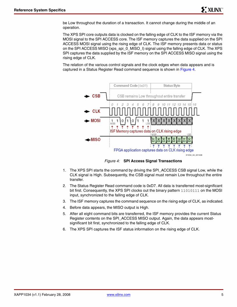
be Low throughout the duration of a transaction. It cannot change during the middle of an operation.
The XPS SPI core outputs data is clocked on the falling edge of CLK to the ISF memory via the MOSI signal to the SPI ACCESS core. The ISF memory captures the data supplied on the SPI ACCESS MOSI signal using the rising edge of CLK. The ISF memory presents data or status on the SPI ACCESS MISO (xps_spi_0_MISO_I) signal using the falling edge of CLK. The XPS SPI captures the data supplied by the ISF memory on the SPI ACCESS MISO signal using the rising edge of CLK.
The relation of the various control signals and the clock edges when data appears and is captured in a Status Register Read command sequence is shown in Figure 4.
1. The XPS SPI starts the command by driving the SPI_ACCESS CSB signal Low, while the CLK signal is High. Subsequently, the CSB signal must remain Low throughout the entire transfer.
2. The Status Register Read command code is 0xD7. All data is transferred most-significant bit first. Consequently, the XPS SPI clocks out the binary pattern 11010111 on the MOSI input, synchronized to the falling edge of CLK.
3. The ISF memory captures the command sequence on the rising edge of CLK, as indicated.
4. Before data appears, the MISO output is High.
5. After all eight command bits are transferred, the ISF memory provides the current Status Register contents on the SPI_ACCESS MISO output. Again, the data appears most-significant bit first, synchronized to the falling edge of CLK.
6. The XPS SPI captures the ISF status information on the rising edge of CLK.
X-Ref Target - Figure 4
Figure 4: SPI Access Signal Transactions
X1034_04_021408
XILISF Library
XAPP1034 (v1.1) February 28, 2008 www.xilinx.com 6
R
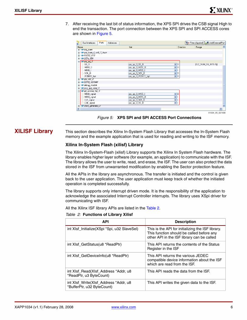
7. After receiving the last bit of status information, the XPS SPI drives the CSB signal High to end the transaction. The port connection between the XPS SPI and SPI ACCESS cores are shown in Figure 5.
XILISF Library This section describes the Xilinx In-System Flash Library that accesses the In-System Flash memory and the example application that is used for reading and writing to the ISF memory.
Xilinx In-System Flash (xilisf) Library
The Xilinx In-System-Flash (xilisf) Library supports the Xilinx In System Flash hardware. The library enables higher layer software (for example, an application) to communicate with the ISF. The library allows the user to write, read, and erase, the ISF. The user can also protect the data stored in the ISF from unwarranted modification by enabling the Sector protection feature.
All the APIs in the library are asynchronous. The transfer is initiated and the control is given back to the user application. The user application must keep track of whether the initiated operation is completed successfully.
The library supports only interrupt driven mode. It is the responsibility of the application to acknowledge the associated Interrupt Controller interrupts. The library uses XSpi driver for communicating with ISF.
All the Xilinx ISF library APIs are listed in the Table 2.
X-Ref Target - Figure 5
Figure 5: XPS SPI and SPI ACCESS Port ConnectionsX1034_05_021408
Table 2: Functions of Library Xilisf
API Description
int XIsf_Initialize(XSpi *Spi, u32 SlaveSel) This is the API for initializing the ISF library. This function should be called before any other API in the ISF library can be called
int XIsf_GetStatus(u8 *ReadPtr) This API returns the contents of the Status Register in the ISF
int XIsf_GetDeviceInfo(u8 *ReadPtr) This API returns the various JEDEC compatible device information about the ISF which are read from the ISF.
int XIsf_Read(XIsf_Address *Addr, u8 *ReadPtr, u3 ByteCount)
This API reads the data from the ISF.
int XIsf_Write(XIsf_Address *Addr, u8 *BufferPtr, u32 ByteCount)
This API writes the given data to the ISF.
XILISF Library
XAPP1034 (v1.1) February 28, 2008 www.xilinx.com 7
R
The Xilinx ISF library (xilisf) is found in the sw_services folder under the project root directory.
Note: A preliminary version of the Xilinx ISF library is included with this application note. Changes to the API may appear in the official EDK release.
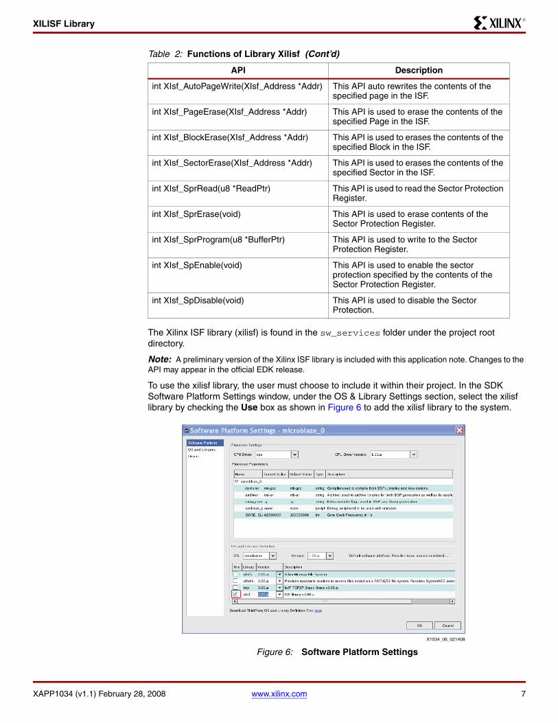
To use the xilisf library, the user must choose to include it within their project. In the SDK Software Platform Settings window, under the OS & Library Settings section, select the xilisf library by checking the Use box as shown in Figure 6 to add the xilisf library to the system.
int XIsf_AutoPageWrite(XIsf_Address *Addr) This API auto rewrites the contents of the specified page in the ISF.
int XIsf_PageErase(XIsf_Address *Addr) This API is used to erase the contents of the specified Page in the ISF.
int XIsf_BlockErase(XIsf_Address *Addr) This API is used to erases the contents of the specified Block in the ISF.
int XIsf_SectorErase(XIsf_Address *Addr) This API is used to erases the contents of the specified Sector in the ISF.
int XIsf_SprRead(u8 *ReadPtr) This API is used to read the Sector Protection Register.
int XIsf_SprErase(void) This API is used to erase contents of the Sector Protection Register.
int XIsf_SprProgram(u8 *BufferPtr) This API is used to write to the Sector Protection Register.
int XIsf_SpEnable(void) This API is used to enable the sector protection specified by the contents of the Sector Protection Register.
int XIsf_SpDisable(void) This API is used to disable the Sector Protection.
X-Ref Target - Figure 6
Figure 6: Software Platform Settings
Table 2: Functions of Library Xilisf (Cont’d)
API Description
X1034_06_021408
ISF Organization
XAPP1034 (v1.1) February 28, 2008 www.xilinx.com 8
R
ISF Organization
This application note will discuss the XC3S700AN device only as it is configured with the Xilinx Spartan-3AN Starter Kit board. Power-of-2 Addressing mode is not used nor discussed. Refer to UG333 Spartan-3AN In-System Flash User Guide for information on other Spartan 3AN devices.
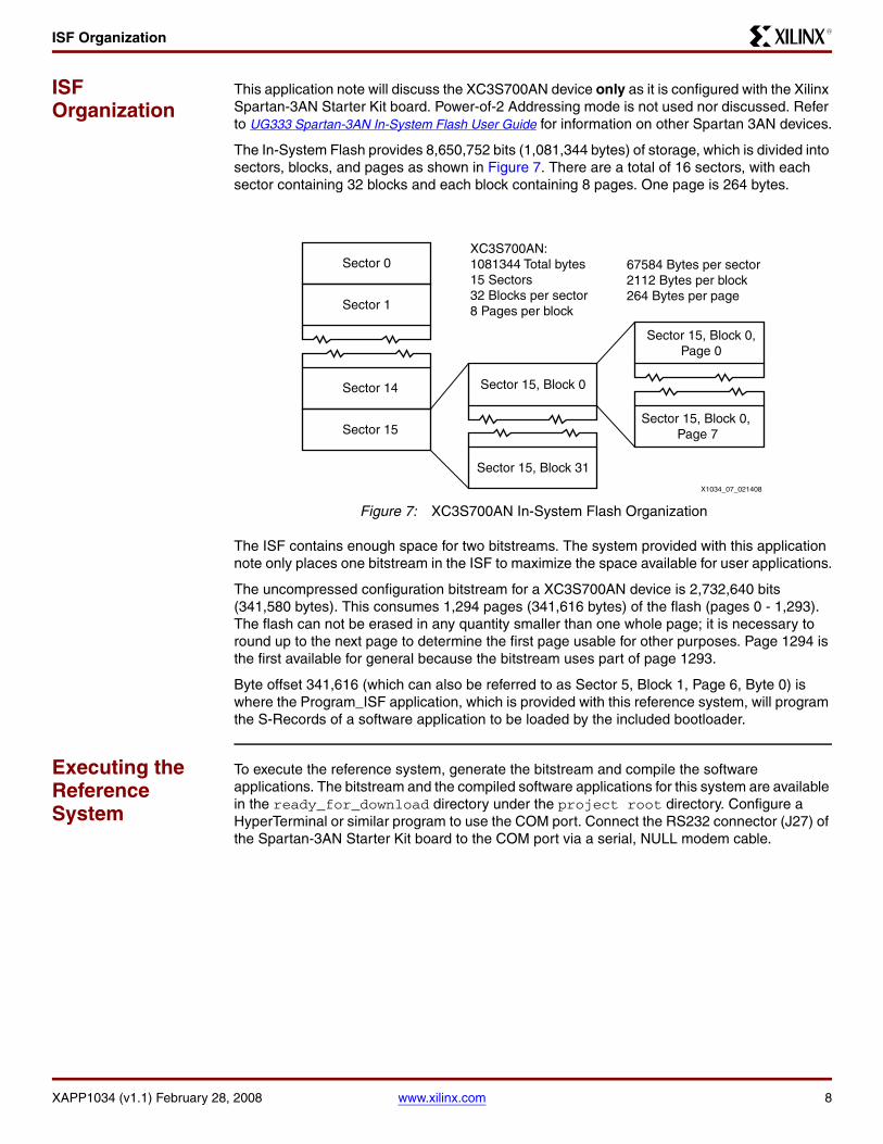
The In-System Flash provides 8,650,752 bits (1,081,344 bytes) of storage, which is divided into sectors, blocks, and pages as shown in Figure 7. There are a total of 16 sectors, with each sector containing 32 blocks and each block containing 8 pages. One page is 264 bytes.
The ISF contains enough space for two bitstreams. The system provided with this application note only places one bitstream in the ISF to maximize the space available for user applications.
The uncompressed configuration bitstream for a XC3S700AN device is 2,732,640 bits (341,580 bytes). This consumes 1,294 pages (341,616 bytes) of the flash (pages 0 - 1,293). The flash can not be erased in any quantity smaller than one whole page; it is necessary to round up to the next page to determine the first page usable for other purposes. Page 1294 is the first available for general because the bitstream uses part of page 1293.
Byte offset 341,616 (which can also be referred to as Sector 5, Block 1, Page 6, Byte 0) is where the Program_ISF application, which is provided with this reference system, will program the S-Records of a software application to be loaded by the included bootloader.
Executing the Reference System
To execute the reference system, generate the bitstream and compile the software applications. The bitstream and the compiled software applications for this system are available in the ready_for_download directory under the project root directory. Configure a HyperTerminal or similar program to use the COM port. Connect the RS232 connector (J27) of the Spartan-3AN Starter Kit board to the COM port via a serial, NULL modem cable.
X-Ref Target - Figure 7
Figure 7: XC3S700AN In-System Flash Organization
Sector 0
Sector 1
Sector 14
Sector 15
Sector 15, Block 0
Sector 15, Block 31
Sector 15, Block 0,Page 0
Sector 15, Block 0, Page 7
XC3S700AN:1081344 Total bytes15 Sectors32 Blocks per sector8 Pages per block
67584 Bytes per sector2112 Bytes per block264 Bytes per page
X1034_07_021408
Executing the Reference System
XAPP1034 (v1.1) February 28, 2008 www.xilinx.com 9
R
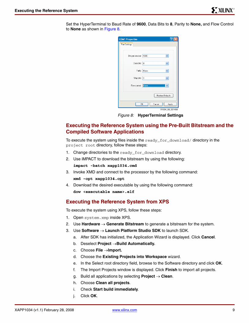
Set the HyperTerminal to Baud Rate of 9600, Data Bits to 8, Parity to None, and Flow Control to None as shown in Figure 8.
Executing the Reference System using the Pre-Built Bitstream and the Compiled Software Applications
To execute the system using files inside the ready_for_download/ directory in the project root directory, follow these steps:
1. Change directories to the ready_for_download directory.
2. Use iMPACT to download the bitstream by using the following:
impact -batch xapp1034.cmd
3. Invoke XMD and connect to the processor by the following command:
xmd -opt xapp1034.opt
4. Download the desired executable by using the following command:
dow <executable name>.elf
Executing the Reference System from XPS
To execute the system using XPS, follow these steps:
1. Open system.xmp inside XPS.
2. Use Hardware → Generate Bitstream to generate a bitstream for the system.
3. Use Software → Launch Platform Studio SDK to launch SDK.
a. After SDK has initialized, the Application Wizard is displayed. Click Cancel.
b. Deselect Project →Build Automatically.
c. Choose File →Import.
d. Choose the Existing Projects into Workspace wizard.
e. In the Select root directory field, browse to the Software directory and click OK.
f. The Import Projects window is displayed. Click Finish to import all projects.
g. Build all applications by selecting Project → Clean.
h. Choose Clean all projects.
i. Check Start build immediately.
j. Click OK.
X-Ref Target - Figure 8
Figure 8: HyperTerminal Settings
X1034_08_021408
The Bootloader
XAPP1034 (v1.1) February 28, 2008 www.xilinx.com 10
R
4. Choose the software application to place in BRAM by selecting Device Configuration → Program Hardware Settings. Select bootloader.elf from the list box. Click Save.
5. Download the bitstream to the board with Device Configuration → Program Hardware.
6. The newly compiled binaries are located in the applicable SDK_projects/<application>/Debug/ subdirectory. Right click on right on the desired project to download the desired application, then select Run As →Run.
a. The Run window appears. If this is the first time that this application is launched with SDK, click New, otherwise select the appropriate project from the list.
b. Click Run.
c. A warning dialog may appear that there is an existing session. Click Yes to proceed with downloading the desired application.
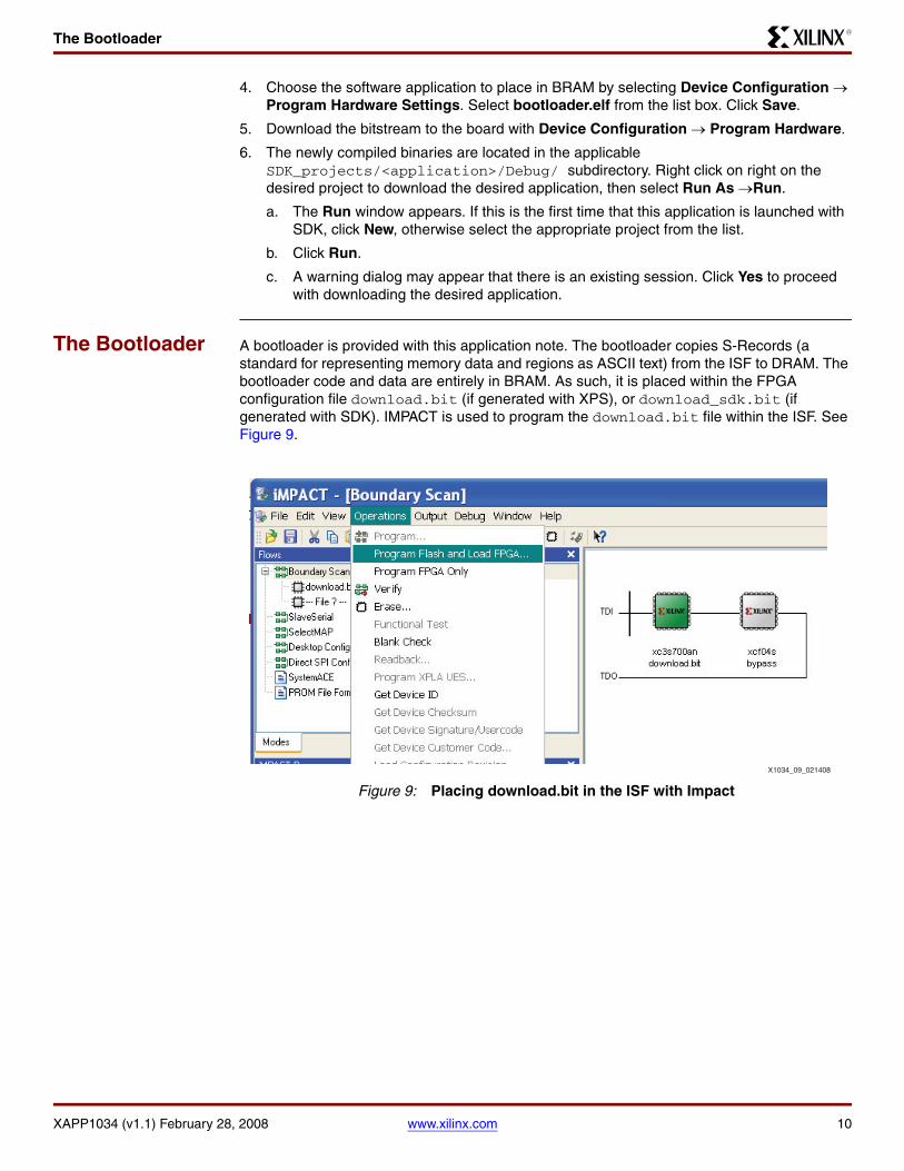
The Bootloader A bootloader is provided with this application note. The bootloader copies S-Records (a standard for representing memory data and regions as ASCII text) from the ISF to DRAM. The bootloader code and data are entirely in BRAM. As such, it is placed within the FPGA configuration file download.bit (if generated with XPS), or download_sdk.bit (if generated with SDK). IMPACT is used to program the download.bit file within the ISF. See Figure 9.
X-Ref Target - Figure 9
Figure 9: Placing download.bit in the ISF with Impact
X1034_09_021408
Program_ISF
XAPP1034 (v1.1) February 28, 2008 www.xilinx.com 11
R
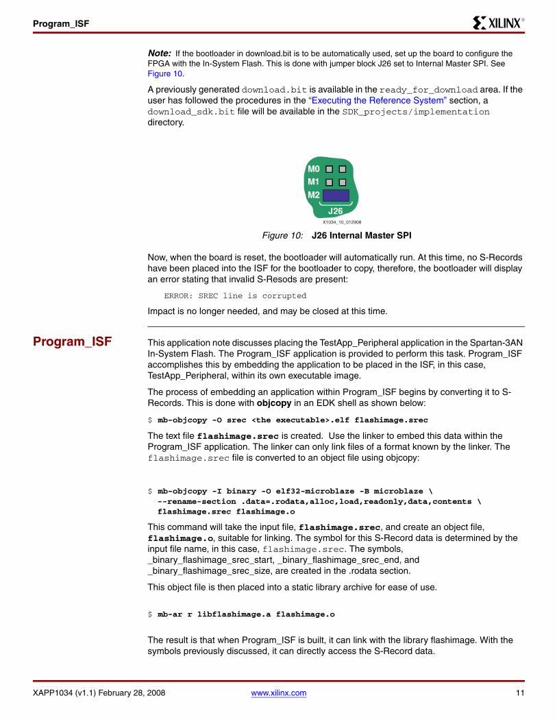
Note: If the bootloader in download.bit is to be automatically used, set up the board to configure the FPGA with the In-System Flash. This is done with jumper block J26 set to Internal Master SPI. See Figure 10.
A previously generated download.bit is available in the ready_for_download area. If the user has followed the procedures in the “Executing the Reference System” section, a download_sdk.bit file will be available in the SDK_projects/implementation directory.
Now, when the board is reset, the bootloader will automatically run. At this time, no S-Records have been placed into the ISF for the bootloader to copy, therefore, the bootloader will display an error stating that invalid S-Resods are present:
ERROR: SREC line is corrupted
Impact is no longer needed, and may be closed at this time.
Program_ISF This application note discusses placing the TestApp_Peripheral application in the Spartan-3AN In-System Flash. The Program_ISF application is provided to perform this task. Program_ISF accomplishes this by embedding the application to be placed in the ISF, in this case, TestApp_Peripheral, within its own executable image.
The process of embedding an application within Program_ISF begins by converting it to S-Records. This is done with objcopy in an EDK shell as shown below:
$ mb-objcopy -O srec <the executable>.elf flashimage.srec
The text file flashimage.srec is created. Use the linker to embed this data within the Program_ISF application. The linker can only link files of a format known by the linker. The flashimage.srec file is converted to an object file using objcopy:
$ mb-objcopy -I binary -O elf32-microblaze -B microblaze \ --rename-section .data=.rodata,alloc,load,readonly,data,contents \ flashimage.srec flashimage.o
This command will take the input file, flashimage.srec, and create an object file, flashimage.o, suitable for linking. The symbol for this S-Record data is determined by the input file name, in this case, flashimage.srec. The symbols, _binary_flashimage_srec_start, _binary_flashimage_srec_end, and _binary_flashimage_srec_size, are created in the .rodata section.
This object file is then placed into a static library archive for ease of use.
$ mb-ar r libflashimage.a flashimage.o
The result is that when Program_ISF is built, it can link with the library flashimage. With the symbols previously discussed, it can directly access the S-Record data.
X-Ref Target - Figure 10
Figure 10: J26 Internal Master SPI
X1034_10_012908
Program_ISF
XAPP1034 (v1.1) February 28, 2008 www.xilinx.com 12
R
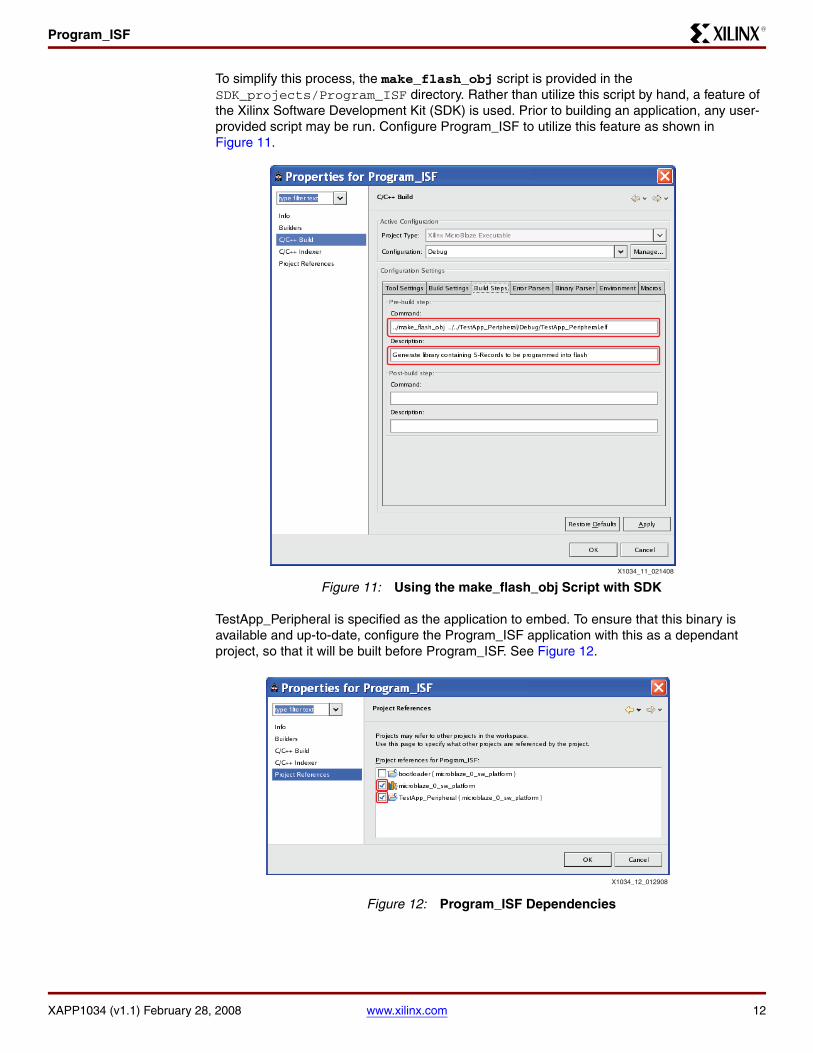
To simplify this process, the make_flash_obj script is provided in the SDK_projects/Program_ISF directory. Rather than utilize this script by hand, a feature of the Xilinx Software Development Kit (SDK) is used. Prior to building an application, any user- provided script may be run. Configure Program_ISF to utilize this feature as shown in Figure 11.
TestApp_Peripheral is specified as the application to embed. To ensure that this binary is available and up-to-date, configure the Program_ISF application with this as a dependant project, so that it will be built before Program_ISF. See Figure 12.
X-Ref Target - Figure 11
Figure 11: Using the make_flash_obj Script with SDK
X-Ref Target - Figure 12
Figure 12: Program_ISF Dependencies
X1034_11_021408
X1034_12_012908
Program_ISF
XAPP1034 (v1.1) February 28, 2008 www.xilinx.com 13
R
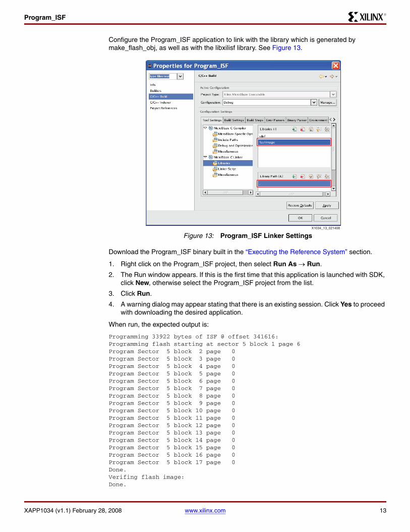
Configure the Program_ISF application to link with the library which is generated by make_flash_obj, as well as with the libxilisf library. See Figure 13.
Download the Program_ISF binary built in the “Executing the Reference System” section.
1. Right click on the Program_ISF project, then select Run As → Run.
2. The Run window appears. If this is the first time that this application is launched with SDK, click New, otherwise select the Program_ISF project from the list.
3. Click Run.
4. A warning dialog may appear stating that there is an existing session. Click Yes to proceed with downloading the desired application.
When run, the expected output is:
Programming 33922 bytes of ISF @ offset 341616:Programming flash starting at sector 5 block 1 page 6Program Sector 5 block 2 page 0Program Sector 5 block 3 page 0Program Sector 5 block 4 page 0Program Sector 5 block 5 page 0Program Sector 5 block 6 page 0Program Sector 5 block 7 page 0Program Sector 5 block 8 page 0Program Sector 5 block 9 page 0Program Sector 5 block 10 page 0Program Sector 5 block 11 page 0Program Sector 5 block 12 page 0Program Sector 5 block 13 page 0Program Sector 5 block 14 page 0Program Sector 5 block 15 page 0Program Sector 5 block 16 page 0Program Sector 5 block 17 page 0Done.Verifing flash image:Done.
X-Ref Target - Figure 13
Figure 13: Program_ISF Linker SettingsX1034_13_021408
References
XAPP1034 (v1.1) February 28, 2008 www.xilinx.com 14
R
When the board is reset by the user, the bootloader should now copy TestApp_Peripheral out of the ISF and execute it as is shown below:
EDK Bootloader:Copying S-Records from flash offset 0x00053670Executing program starting at address: 00000000-- Entering main() --
Running GpioOutputExample() for LEDs_8Bit...GpioOutputExample PASSED.
Running UartLiteSelfTestExample() for debug_module...UartLiteSelfTestExample PASSED-- Exiting main() --
References 1. DS570 XPS Serial Peripheral Interface v1.00a Product Specification
2. UG332 Spartan-3 Generation Configuration User Guide
3. UG333 Spartan-3AN FPGA In-System Flash User Guide
4. UG334 Spartan-3A/3AN Starter Kit Board User Guide
Revision History
The following table shows the revision history for this document.
Notice of Disclaimer
Xilinx is disclosing this Application Note to you “AS-IS” with no warranty of any kind. This Application Noteis one possible implementation of this feature, application, or standard, and is subject to change withoutfurther notice from Xilinx. You are responsible for obtaining any rights you may require in connection withyour use or implementation of this Application Note. XILINX MAKES NO REPRESENTATIONS ORWARRANTIES, WHETHER EXPRESS OR IMPLIED, STATUTORY OR OTHERWISE, INCLUDING,WITHOUT LIMITATION, IMPLIED WARRANTIES OF MERCHANTABILITY, NONINFRINGEMENT, ORFITNESS FOR A PARTICULAR PURPOSE. IN NO EVENT WILL XILINX BE LIABLE FOR ANY LOSS OFDATA, LOST PROFITS, OR FOR ANY SPECIAL, INCIDENTAL, CONSEQUENTIAL, OR INDIRECTDAMAGES ARISING FROM YOUR USE OF THIS APPLICATION NOTE.
Date Version Revision
11/21/07 1.0 Initial Xilinx release.
2/28/08 1.1 Updated to include bootloader