Embed Size (px)
Citation preview
R Series® Configuration Manual
9650-0902-01 Rev. K

The issue date for the R Series Configuration Guide (REF 9650-0902-01 Rev. K) is May, 2012.
If more than 3 years have elapsed since the issue date, contact ZOLL Medical Corporation to determine if additional product information updates are available.
© 2012 ZOLL Medical Corporation. All rights reserved. R Series, pedi-padz, Real CPR Help, Code-Ready, and OneStep are trademarks or registered trademarks of ZOLL Medical Corporation in the United States and/or other countries.
Masimo is a registered trademark of Masimo Corporation in the United States and/or other countries.
All other trademarks are the property of their respective owners.
0123
ZOLL Medical Corporation269 Mill RoadChelmsford, MA USA 01824-4105
ZOLL International Holding B.V.Newtonweg 186662 PV ELST The Netherlands
9650-0902-01 Rev. K ZOLL R Series Configuration Manual i
Table of Contents
Chapter 1 Introduction
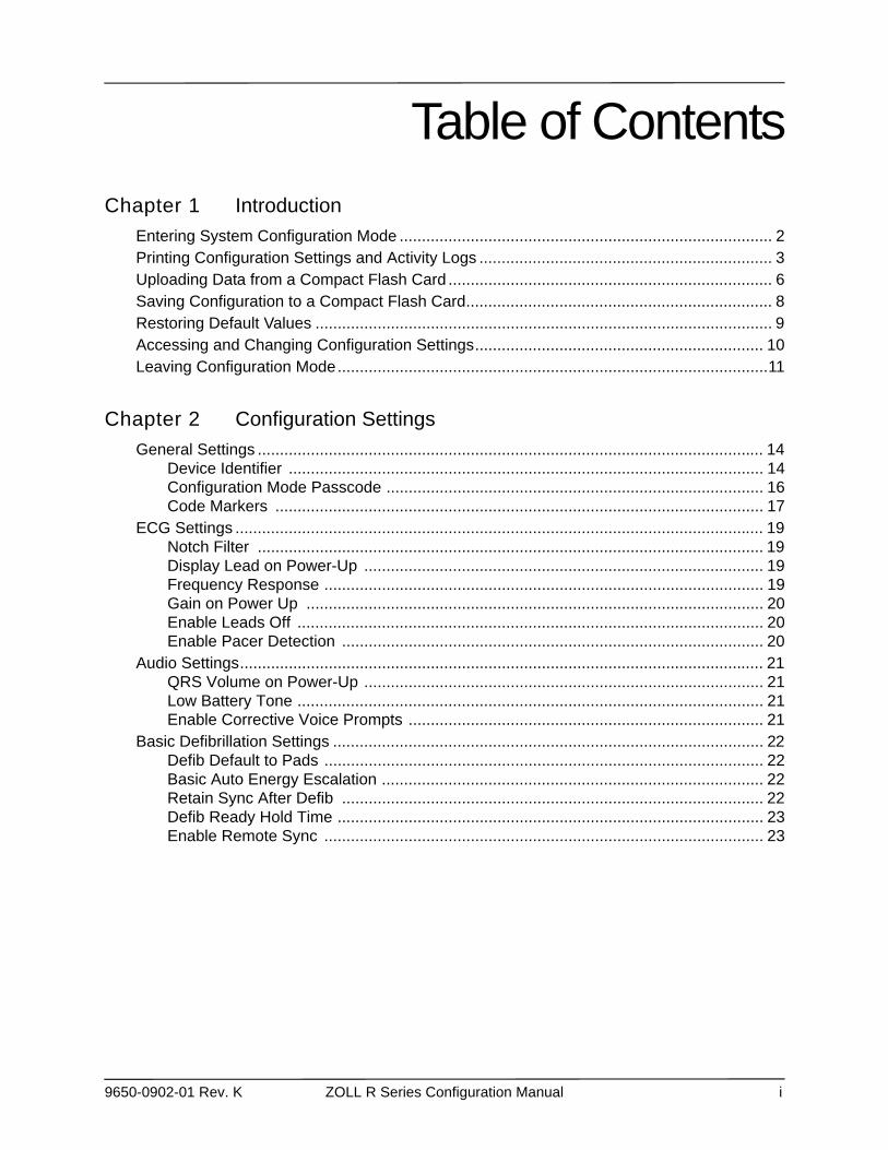
Entering System Configuration Mode .................................................................................... 2Printing Configuration Settings and Activity Logs .................................................................. 3Uploading Data from a Compact Flash Card ......................................................................... 6Saving Configuration to a Compact Flash Card..................................................................... 8Restoring Default Values ....................................................................................................... 9Accessing and Changing Configuration Settings................................................................. 10Leaving Configuration Mode.................................................................................................11
Chapter 2 Configuration Settings
General Settings .................................................................................................................. 14Device Identifier ........................................................................................................... 14Configuration Mode Passcode ..................................................................................... 16Code Markers .............................................................................................................. 17
ECG Settings ....................................................................................................................... 19Notch Filter .................................................................................................................. 19Display Lead on Power-Up .......................................................................................... 19Frequency Response ................................................................................................... 19Gain on Power Up ....................................................................................................... 20Enable Leads Off ......................................................................................................... 20Enable Pacer Detection ............................................................................................... 20
Audio Settings...................................................................................................................... 21QRS Volume on Power-Up .......................................................................................... 21Low Battery Tone ......................................................................................................... 21Enable Corrective Voice Prompts ................................................................................ 21
Basic Defibrillation Settings ................................................................................................. 22Defib Default to Pads ................................................................................................... 22Basic Auto Energy Escalation ...................................................................................... 22Retain Sync After Defib ............................................................................................... 22Defib Ready Hold Time ................................................................................................ 23Enable Remote Sync ................................................................................................... 23
TABLE OF CONTENTS
ii www.zoll.com 9650-0902-01 Rev. K
Advisory Defib...................................................................................................................... 24Energy Level: Shock 1 ................................................................................................. 24Energy Level: Shock 2 ................................................................................................. 25Energy Level: Shock 3 ................................................................................................. 25Ped Energy Level Shock 1 .......................................................................................... 25Ped Energy Level Shock 2 .......................................................................................... 26Ped Energy Level Shock 3 .......................................................................................... 26Auto Analyze ................................................................................................................ 26Enable Check Pulse Prompt ........................................................................................ 27Check Patient Prompt .................................................................................................. 27Auto Charge in Advisory Mode .................................................................................... 27Enable Voice in Advisory Mode ................................................................................... 28Display DO CPR Message .......................................................................................... 28CPR Message After No Shock Advised ....................................................................... 29CPR Message After Shock .......................................................................................... 29Stacked Shocks ........................................................................................................... 30Restart Analysis After CPR .......................................................................................... 30CPR Interval ................................................................................................................ 30
CPR Settings ....................................................................................................................... 31Enable CPR Voice Prompts ......................................................................................... 31Enable CPR Display .................................................................................................... 31Enable CPR Metronome .............................................................................................. 31Target CPR Depth ....................................................................................................... 31Display Fully Release Prompt ...................................................................................... 32
Pace Settings....................................................................................................................... 33Pace Rate Setting on Power-Up .................................................................................. 33Async Softkey in Pace Mode ....................................................................................... 33
Alarms Settings.................................................................................................................... 34Alarm Limits at Power Up ............................................................................................ 35Alarms Active at Power Up .......................................................................................... 39
Display Settings ................................................................................................................... 40Display Time ................................................................................................................ 40Select Trace 2 At Power Up ........................................................................................ 40Select Trace 3 At Power Up ........................................................................................ 41ECG Color ................................................................................................................... 41SpO2 Color .................................................................................................................. 41CPR Color .................................................................................................................... 41EtCO2 Color ................................................................................................................. 42NIBP Color ................................................................................................................... 42SPO2 at Power Up ....................................................................................................... 42
9650-0902-01 Rev. K ZOLL R Series Configuration Manual iii
NIBP Settings (Optional)...................................................................................................... 43Blood Pressure Units ................................................................................................... 43Trigger NIBP Meas on BP Alarm ................................................................................. 43Trigger NIBP Meas on HR Alarm ................................................................................. 43NIBP Auto Interval Default ........................................................................................... 44Adult Initial Cuff Inflation .............................................................................................. 44Pediatric Initial Cuff Inflation ........................................................................................ 44Neonatal Initial Cuff Inflation ........................................................................................ 44NIBP Patient Mode at Power Up ................................................................................. 45NIBP Button Press & Hold ........................................................................................... 45Enable Motion Tolerance ............................................................................................. 45
EtCO2 Settings (Optional).................................................................................................... 46Default EtCO2 Units ..................................................................................................... 46Displayed Zoom Level ................................................................................................. 46Default EtCO2 Comp Setting ....................................................................................... 46Power Save Mode at Power Up ................................................................................... 47EtCO2 Average On Power Up ..................................................................................... 47
Printer & Report Settings ..................................................................................................... 48Set Report Restart Delays ........................................................................................... 48Auto Generate Strips ................................................................................................... 48Print 3 Leads When Leads Sel. ................................................................................... 48
Readiness Test Settings ...................................................................................................... 49Automatic Readiness Test ........................................................................................... 49Readiness Test Time ................................................................................................... 49Print Readiness Test Results ...................................................................................... 49Enable Readiness Test Audible Alert (Future Use) ..................................................... 50One Step Padz Installed .............................................................................................. 50
AED Mode ........................................................................................................................... 51Display ECG in AED Mode .......................................................................................... 51Display HR in AED Mode ............................................................................................. 51Manual Confirm Enable ............................................................................................... 51Extra CPR Interval Before 1st Analysis ....................................................................... 52Duration of Extra CPR Interval .................................................................................... 52Display Remaining CPR Timer .................................................................................... 52
TABLE OF CONTENTS
iv www.zoll.com 9650-0902-01 Rev. K
Wi-Fi Settings (Optional)...................................................................................................... 53Full Disclosure Transfer Mode ..................................................................................... 53Defib History Transfer Mode ........................................................................................ 53Infrastructure Mode Options ........................................................................................ 53DHCP/Static IP ............................................................................................................ 53Local IP Address .......................................................................................................... 54Gateway IP Address .................................................................................................... 55Subnet Mask ................................................................................................................ 56Use DNS ...................................................................................................................... 57Primary/Secondary DNS IP Address ........................................................................... 57SSID Names (up to 2 entries) ...................................................................................... 58Server Name (Full Disclosure) ..................................................................................... 59Server IP (Full Disclosure) ........................................................................................... 60Server Port (Full Disclosure) ........................................................................................ 61Server Name (Defib History) ........................................................................................ 62Server IP (Defib History) .............................................................................................. 63Server Port (Defib History) ........................................................................................... 65Passphrase/Keys (up to 2 entries) ............................................................................... 66Enable Report ID ......................................................................................................... 67Wi-Fi Region ................................................................................................................ 67Wi-Fi Radio .................................................................................................................. 67
9650-0902-01 Rev. K 1
Chapter 1Introduction
The R Series® is designed with several user selectable features that allow operators to configure the device according to their protocols and local requirements. This manual describes the configuration settings (options and defaults) and how to change them for ALS, Plus, and BLS models. References to AED settings are for Plus and BLS models only.
Note: Your unit may not contain all features listed. For BLS/Plus units, some features are available in manual mode operation only.
For more information, see the following sections:
• “Entering System Configuration Mode” on page 2• “Printing Configuration Settings and Activity Logs” on page 3• “Uploading Data from a Compact Flash Card” on page 6• “Saving Configuration to a Compact Flash Card” on page 8• “Restoring Default Values” on page 9• “Accessing and Changing Configuration Settings” on page 10• “Leaving Configuration Mode” on page 11
Chapter 1 Introduction
2 9650-0902-01 Rev. K
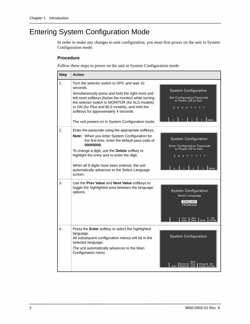
Entering System Configuration ModeIn order to make any changes to unit configuration, you must first power on the unit in System Configuration mode.
Procedure
Follow these steps to power on the unit in System Configuration mode:
Step Action
1. Turn the selector switch to OFF, and wait 10 seconds.
Simultaneously press and hold the right-most and left-most softkeys (below the monitor) while turning the selector switch to MONITOR (for ALS models) or ON (for Plus and BLS models), and hold the softkeys for approximately 4 seconds.
The unit powers on in System Configuration mode.
2. Enter the passcode using the appropriate softkeys.
Note: When you enter System Configuration for the first time, enter the default pass code of 00000000.
To change a digit, use the Delete softkey to highlight the entry and re-enter the digit.
When all 8 digits have been entered, the unit automatically advances to the Select Language screen.
3. Use the Prev Value and Next Value softkeys to toggle the highlighted area between the language options.
4. Press the Enter softkey to select the highlighted language. All subsequent configuration menus will be in the selected language.
The unit automatically advances to the Main Configuration menu.
System Configuration
Set Configuration Passcodeor Power Off to Exit
0 0 0 0 ? ? ? ?
0
3
Delete 2
1
System Configuration
Enter Configuration Passcodeor Power Off to Exit
0 0 0 ? ? ? ? ?
0
3
Delete 2
1
Enter
Exit
ConfigNextValue
PrevValue
System ConfigurationSelect Language
ENGLISHFRANCAIS
System Configuration
Change Config
Exit Config
Read From Card
Restore Defaults
Printing Configuration Settings and Activity Logs
9650-0902-01 Rev. K 3
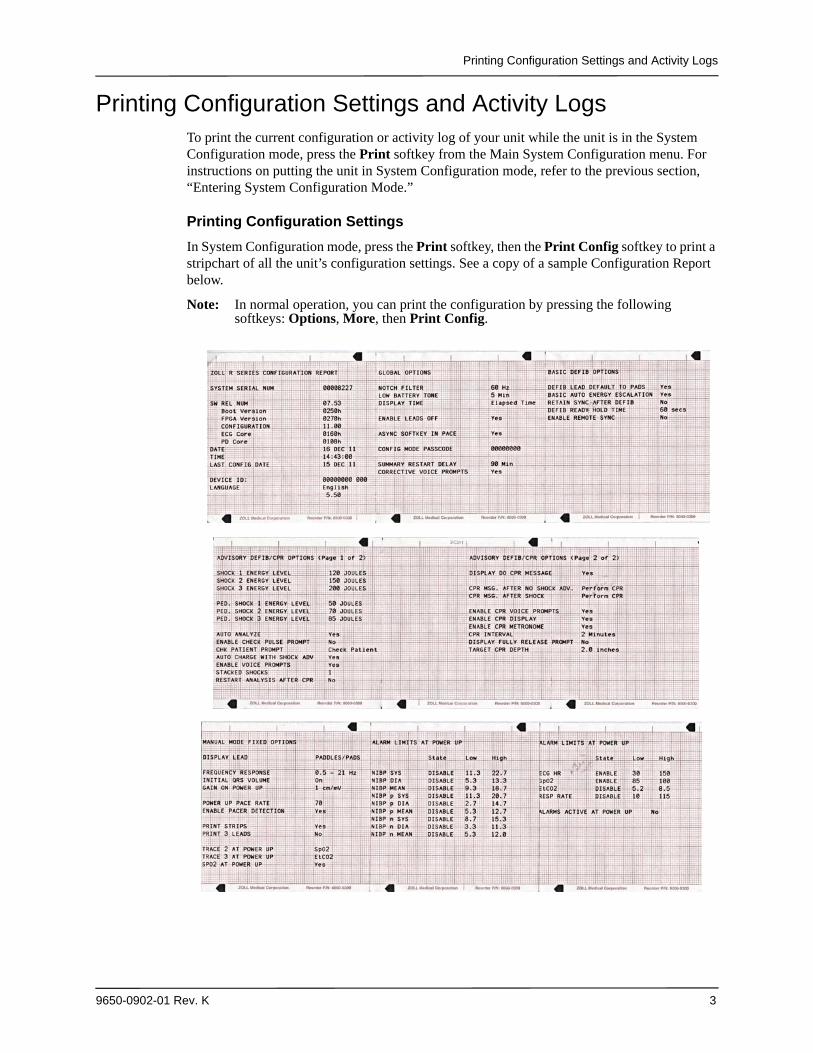
Printing Configuration Settings and Activity LogsTo print the current configuration or activity log of your unit while the unit is in the System Configuration mode, press the Print softkey from the Main System Configuration menu. For instructions on putting the unit in System Configuration mode, refer to the previous section, “Entering System Configuration Mode.”
Printing Configuration Settings
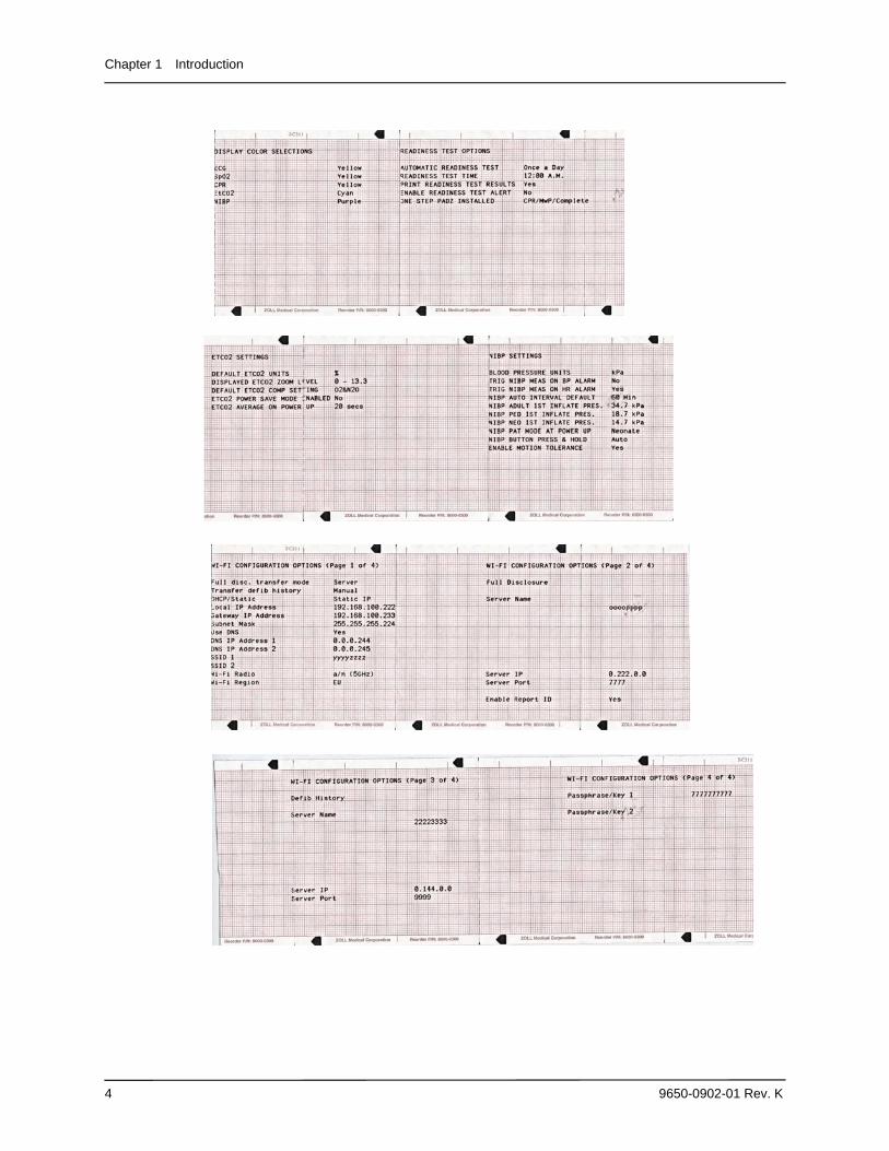
In System Configuration mode, press the Print softkey, then the Print Config softkey to print a stripchart of all the unit’s configuration settings. See a copy of a sample Configuration Report below.
Note: In normal operation, you can print the configuration by pressing the following softkeys: Options, More, then Print Config.
Chapter 1 Introduction
4 9650-0902-01 Rev. K
Printing Configuration Settings and Activity Logs
9650-0902-01 Rev. K 5
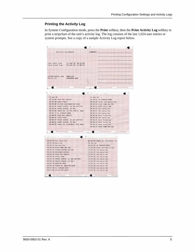
Printing the Activity Log
In System Configuration mode, press the Print softkey, then the Print Activity Log softkey to print a stripchart of the unit’s activity log. The log consists of the last 1,024 user entries or system prompts. See a copy of a sample Activity Log report below.
Chapter 1 Introduction
6 9650-0902-01 Rev. K
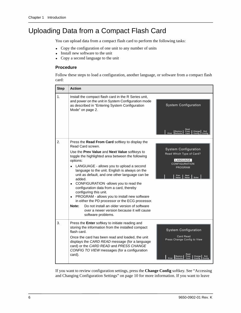
Uploading Data from a Compact Flash CardYou can upload data from a compact flash card to perform the following tasks:
• Copy the configuration of one unit to any number of units• Install new software to the unit• Copy a second language to the unit
Procedure
Follow these steps to load a configuration, another language, or software from a compact flash card:
If you want to review configuration settings, press the Change Config softkey. See “Accessing and Changing Configuration Settings” on page 10 for more information. If you want to leave
Step Action
1. Install the compact flash card in the R Series unit, and power on the unit in System Configuration mode as described in “Entering System Configuration Mode” on page 2.
2. Press the Read From Card softkey to display the Read Card screen.
Use the Prev Value and Next Value softkeys to toggle the highlighted area between the following options:
• LANGUAGE - allows you to upload a second language to the unit. English is always on the unit as default, and one other language can be added.
• CONFIGURATION -allows you to read the configuration data from a card, thereby configuring this unit.
• PROGRAM - allows you to install new software in either the PD processor or the ECG processor.
Note: Do not install an older version of software over a newer version because it will cause software problems.
3. Press the Enter softkey to initiate reading and storing the information from the installed compact flash card.
Once the card has been read and loaded, the unit displays the CARD READ message (for a language card) or the CARD READ and PRESS CHANGE CONFIG TO VIEW messages (for a configuration card).
System Configuration
Change Config
Exit Config
Read From Card
Restore Defaults
Enter
NextValue
PrevValue
System ConfigurationRead Which Type of Card?
LANGUAGECONFIGURATION
PROGRAM
System Configuration
Card ReadPress Change Config to View
Print ChangeConfig
Exit
Config
ReadFromCard
RestoreDefaults
Uploading Data from a Compact Flash Card
9650-0902-01 Rev. K 7
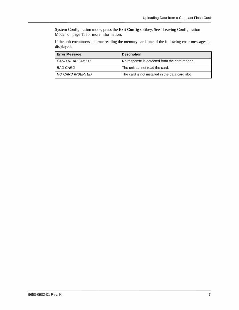
System Configuration mode, press the Exit Config softkey. See “Leaving Configuration Mode” on page 11 for more information.
If the unit encounters an error reading the memory card, one of the following error messages is displayed:
Error Message Description
CARD READ FAILED No response is detected from the card reader.
BAD CARD The unit cannot read the card.
NO CARD INSERTED The card is not installed in the data card slot.
Chapter 1 Introduction
8 9650-0902-01 Rev. K
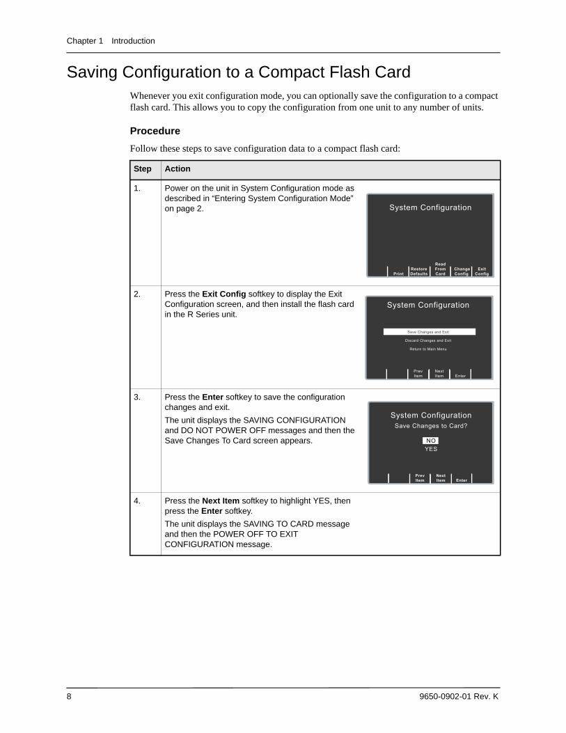
Saving Configuration to a Compact Flash CardWhenever you exit configuration mode, you can optionally save the configuration to a compact flash card. This allows you to copy the configuration from one unit to any number of units.
Procedure
Follow these steps to save configuration data to a compact flash card:
Step Action
1. Power on the unit in System Configuration mode as described in “Entering System Configuration Mode” on page 2.
2. Press the Exit Config softkey to display the Exit Configuration screen, and then install the flash card in the R Series unit.
3. Press the Enter softkey to save the configuration changes and exit.
The unit displays the SAVING CONFIGURATION and DO NOT POWER OFF messages and then the Save Changes To Card screen appears.
4. Press the Next Item softkey to highlight YES, then press the Enter softkey.
The unit displays the SAVING TO CARD message and then the POWER OFF TO EXIT CONFIGURATION message.
System Configuration
Change Config
Exit Config
Read From Card
Restore Defaults
Enter
NextItem
PrevItem
System Configuration
Save Changes and Exit
Discard Changes and Exit
Return to Main Menu
Enter
NextItem
PrevItem
System ConfigurationSave Changes to Card?
NOYES
Restoring Default Values
9650-0902-01 Rev. K 9
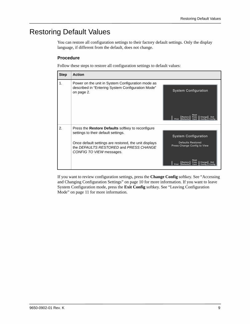
Restoring Default ValuesYou can restore all configuration settings to their factory default settings. Only the display language, if different from the default, does not change.
Procedure
Follow these steps to restore all configuration settings to default values:
If you want to review configuration settings, press the Change Config softkey. See “Accessing and Changing Configuration Settings” on page 10 for more information. If you want to leave System Configuration mode, press the Exit Config softkey. See “Leaving Configuration Mode” on page 11 for more information.
Step Action
1. Power on the unit in System Configuration mode as described in “Entering System Configuration Mode” on page 2.
2. Press the Restore Defaults softkey to reconfigure settings to their default settings.
Once default settings are restored, the unit displays the DEFAULTS RESTORED and PRESS CHANGE CONFIG TO VIEW messages.
System Configuration
Change Config
Exit Config
Read From Card
Restore Defaults
System Configuration
Defaults Restored Press Change Config to View
Print Change Config
Exit Config
Read From Card
Restore Defaults
Chapter 1 Introduction
10 9650-0902-01 Rev. K
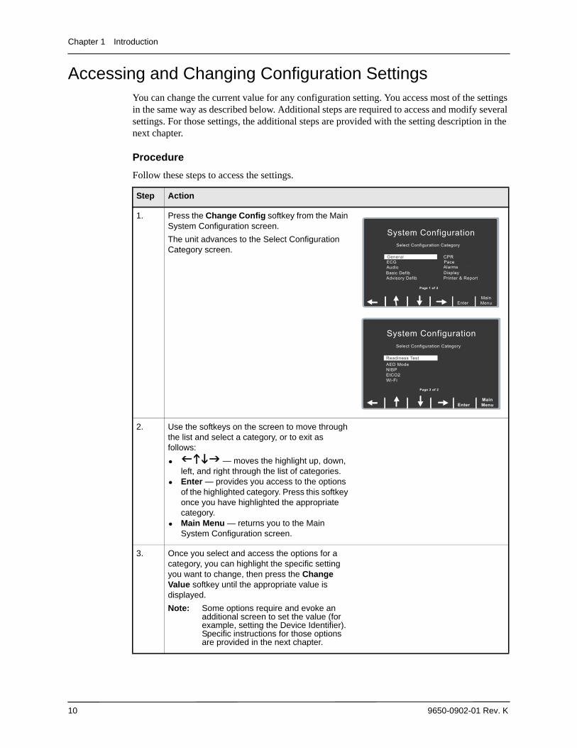
Accessing and Changing Configuration SettingsYou can change the current value for any configuration setting. You access most of the settings in the same way as described below. Additional steps are required to access and modify several settings. For those settings, the additional steps are provided with the setting description in the next chapter.
Procedure
Follow these steps to access the settings.
Step Action
1. Press the Change Config softkey from the Main System Configuration screen.
The unit advances to the Select Configuration Category screen.
2. Use the softkeys on the screen to move through the list and select a category, or to exit as follows:
• — moves the highlight up, down, left, and right through the list of categories.
• Enter — provides you access to the options of the highlighted category. Press this softkey once you have highlighted the appropriate category.
• Main Menu — returns you to the Main System Configuration screen.
3. Once you select and access the options for a category, you can highlight the specific setting you want to change, then press the Change Value softkey until the appropriate value is displayed.
Note: Some options require and evoke an additional screen to set the value (for example, setting the Device Identifier). Specific instructions for those options are provided in the next chapter.
Enter
System Configuration
Select Configuration Category
Set/Review
MainMenu
GeneralECGAudioBasic DefibAdvisory Defib
CPRPaceAlarmsDisplayPrinter & Report
Page 1 of 2
Enter
System Configuration
Select Configuration Category
Main Menu
Readiness TestAED ModeNIBPEtCO2Wi-Fi
Page 2 of 2
Leaving Configuration Mode
9650-0902-01 Rev. K 11
Leaving Configuration Mode
Procedure
Follow the step below to leave System Configuration mode:
4. When you are finished, you can either press the Category List softkey to return to the Category screen, or press the Prev Item or Next Item softkey to move to another option whose settings you want to modify.
Step Action
Step Action
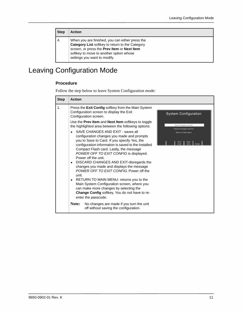
1. Press the Exit Config softkey from the Main System Configuration screen to display the Exit Configuration screen.
Use the Prev Item and Next Item softkeys to toggle the highlighted area between the following options:
• SAVE CHANGES AND EXIT - saves all configuration changes you made and prompts you to Save to Card. If you specify Yes, the configuration information is saved to the installed Compact Flash card. Lastly, the message POWER OFF TO EXIT CONFIG is displayed. Power off the unit.
• DISCARD CHANGES AND EXIT-disregards the changes you made and displays the message POWER OFF TO EXIT CONFIG. Power off the unit.
• RETURN TO MAIN MENU- returns you to the Main System Configuration screen, where you can make more changes by selecting the Change Config softkey. You do not have to re-enter the passcode.
Note: No changes are made if you turn the unit off without saving the configuration.
Enter
NextItem
PrevItem
System Configuration
Save Changes and Exit
Discard Changes and Exit
Return to Main Menu

Chapter 1 Introduction
12 9650-0902-01 Rev. K
9650-0902-01 Rev. K 13
Chapter 2Configuration Settings
This chapter describes all of the configuration settings on the R Series and includes the following sections.
• “General Settings” on page 14• “ECG Settings” on page 19•
• “Basic Defibrillation Settings” on page 22• “Advisory Defib” on page 24• “CPR Settings” on page 31• “Pace Settings” on page 33• “Alarms Settings” on page 34• “Display Settings” on page 40• “NIBP Settings (Optional)” on page 43• “EtCO2 Settings (Optional)” on page 46• “Printer & Report Settings” on page 48• “Readiness Test Settings” on page 49• “AED Mode” on page 51• “Wi-Fi Settings (Optional)” on page 53
Note: The instructions in this chapter assume that you powered on the unit in System Configuration mode as described in “Entering System Configuration Mode” on page 2, and are familiar with how to access the settings, see “Accessing and Changing Configuration Settings” on page 10.
Chapter 2 Configuration Settings
14 9650-0902-01 Rev. K
General SettingsGeneral settings are attributes that affect the unit’s basic operation and accessibility and include:
• Device Identifier• Configuration Mode Passcode• Code Markers
Device Identifier
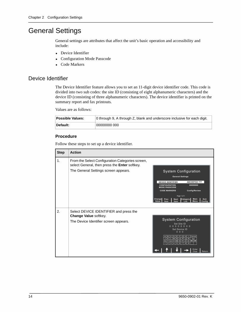
The Device Identifier feature allows you to set an 11-digit device identifier code. This code is divided into two sub codes: the site ID (consisting of eight alphanumeric characters) and the device ID (consisting of three alphanumeric characters). The device identifier is printed on the summary report and fax printouts.
Values are as follows:
Procedure
Follow these steps to set up a device identifier.
Possible Values: 0 through 9, A through Z, blank and underscore inclusive for each digit.
Default: 00000000 000
Step Action
1. From the Select Configuration Categories screen, select General, then press the Enter softkey.
The General Settings screen appears.
2. Select DEVICE IDENTIFIER and press the Change Value softkey.
The Device Identifier screen appears.
Next Item
Prev Item
System Configuration
General Settings
Set/Review CONFIGURATION MODE PASSCODE
CODE MARKERS
00000000
Config/Review
Main Menu
Exit Config
Category List
Change Value
DEVICE IDENTIFIER ABCDEFGH 777
Page 1 of 1
System Configuration
Set Site ID0 0 0 0 0 0 0 0
Set Device ID 0 0 0
A
1
JS
B
2
KT
C
3
LU
D
4
MV
E
5
NW
F
6
OX
G
7
P,
H
8
Q0
I
9
RCancel
Del
ReturnEnterChar
Y Z_
><
General Settings
9650-0902-01 Rev. K 15
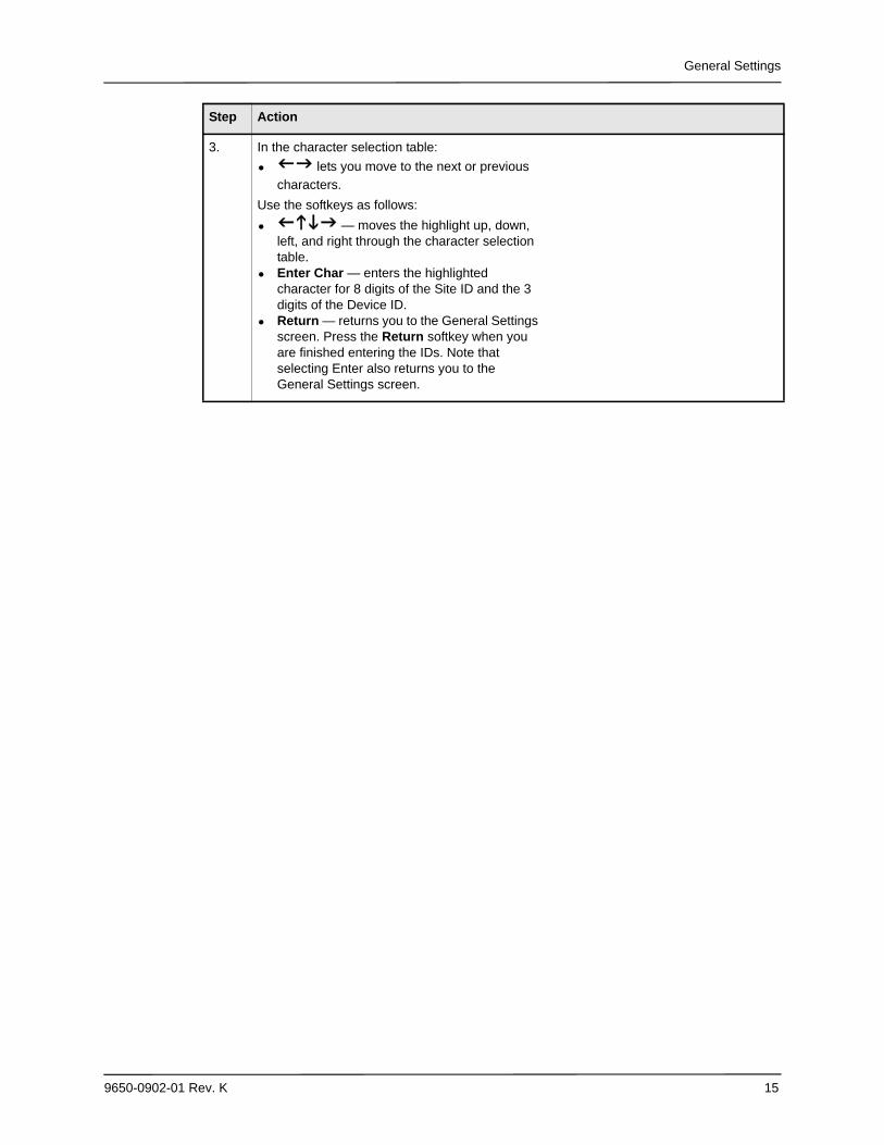
3. In the character selection table:
• lets you move to the next or previous
characters.
Use the softkeys as follows:
• — moves the highlight up, down, left, and right through the character selection table.
• Enter Char — enters the highlighted character for 8 digits of the Site ID and the 3 digits of the Device ID.
• Return — returns you to the General Settings screen. Press the Return softkey when you are finished entering the IDs. Note that selecting Enter also returns you to the General Settings screen.
Step Action
Chapter 2 Configuration Settings
16 9650-0902-01 Rev. K
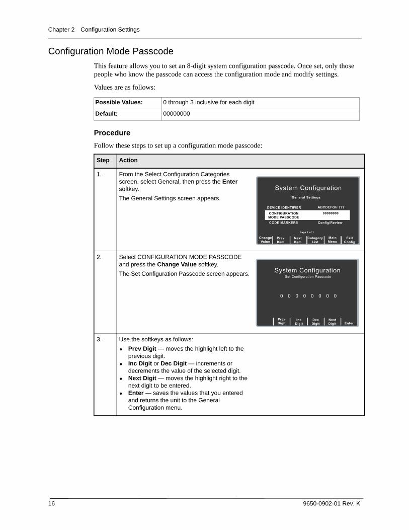
Configuration Mode Passcode
This feature allows you to set an 8-digit system configuration passcode. Once set, only those people who know the passcode can access the configuration mode and modify settings.
Values are as follows:
Procedure
Follow these steps to set up a configuration mode passcode:
Possible Values: 0 through 3 inclusive for each digit
Default: 00000000
Step Action
1. From the Select Configuration Categories screen, select General, then press the Enter softkey.
The General Settings screen appears.
2. Select CONFIGURATION MODE PASSCODE and press the Change Value softkey.
The Set Configuration Passcode screen appears.
3. Use the softkeys as follows:
• Prev Digit — moves the highlight left to the previous digit.
• Inc Digit or Dec Digit — increments or decrements the value of the selected digit.
• Next Digit — moves the highlight right to the next digit to be entered.
• Enter — saves the values that you entered and returns the unit to the General Configuration menu.
NextItem
PrevItem
System Configuration
General Settings
Set/Review
CODE MARKERS Config/Review
MainMenu
ExitConfig
CategoryList
ChangeValue
DEVICE IDENTIFIER ABCDEFGH 777
Page 1 of 1
00000000CONFIGURATIONMODE PASSCODE
PrevDigit
NextDigit
Enter
DecDigit
Inc
Digit
System Configuration Set Configuration Passcode
0 0 0 0 0 0 0 0
General Settings
9650-0902-01 Rev. K 17
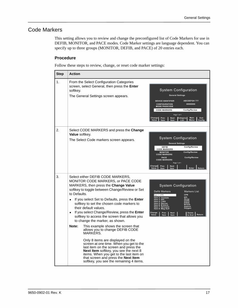
Code Markers
This setting allows you to review and change the preconfigured list of Code Markers for use in DEFIB, MONITOR, and PACE modes. Code Marker settings are language dependent. You can specify up to three groups (MONITOR, DEFIB, and PACE) of 20 entries each.
Procedure
Follow these steps to review, change, or reset code marker settings:
Step Action
1. From the Select Configuration Categories screen, select General, then press the Enter softkey.
The General Settings screen appears.
2. Select CODE MARKERS and press the Change Value softkey.
The Select Code markers screen appears.
3. Select either DEFIB CODE MARKERS, MONITOR CODE MARKERS, or PACE CODE MARKERS, then press the Change Value softkey to toggle between Change/Review or Set to Defaults.
• If you select Set to Defaults, press the Enter softkey to set the chosen code markers to their default values.
• If you select Change/Review, press the Enter softkey to access the screen that allows you to change the marker, as shown.
Note: This example shows the screen that allows you to change DEFIB CODE MARKERS.
Only 8 items are displayed on the screen at one time. When you get to the last item on the screen and press the Next Item softkey, you see the next 8 items. When you get to the last item on that screen and press the Next Item softkey, you see the remaining 4 items.
NextItem
PrevItem
System Configuration
General Settings
Set/Review
MainMenu
ExitConfig
CategoryList
ChangeValue
DEVICE IDENTIFIER ABCDEFGH 777
Page 1 of 1
00000000CONFIGURATIONMODE PASSCODE
CODE MARKERS Config/Review
NextItem
PrevItem
System Configuration
General Settings
Set/Review
Enter Return
ChangeValue
PACECODE MARKERS
Config/Review
Page 1 of 1
Config/ReviewMONITORCODE MARKERS
DEFIBCODE MARKERS
Config/Review
ReturnNextItem
PrevItem
System Configuration
Item 2: Intubate Item 3: EPI
CPRItem 1: CPR
Defib Markers Markers List
Item 4: LIDO
Item 5: Narcan
Item 6: B-block
Item 7: Atrovent
Item 8: Mag Sulf
EPI
Atrop
DOPA
PHEN
Bicarb
Aspirin
Oxygen
ChangeValue
Deleteto End
Chapter 2 Configuration Settings
18 9650-0902-01 Rev. K
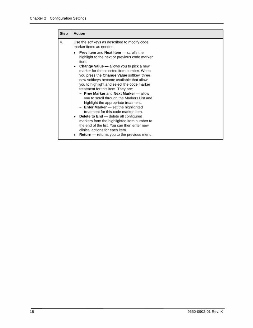
4. Use the softkeys as described to modify code marker items as needed:
• Prev Item and Next Item — scrolls the highlight to the next or previous code marker item.
• Change Value — allows you to pick a new marker for the selected item number. When you press the Change Value softkey, three new softkeys become available that allow you to highlight and select the code marker treatment for this item. They are:— Prev Marker and Next Marker — allow
you to scroll through the Markers List and highlight the appropriate treatment.
— Enter Marker — set the highlighted treatment for this code marker item.
• Delete to End — delete all configured markers from the highlighted item number to the end of the list. You can then enter new clinical actions for each item.
• Return — returns you to the previous menu.
Step Action
ECG Settings
9650-0902-01 Rev. K 19
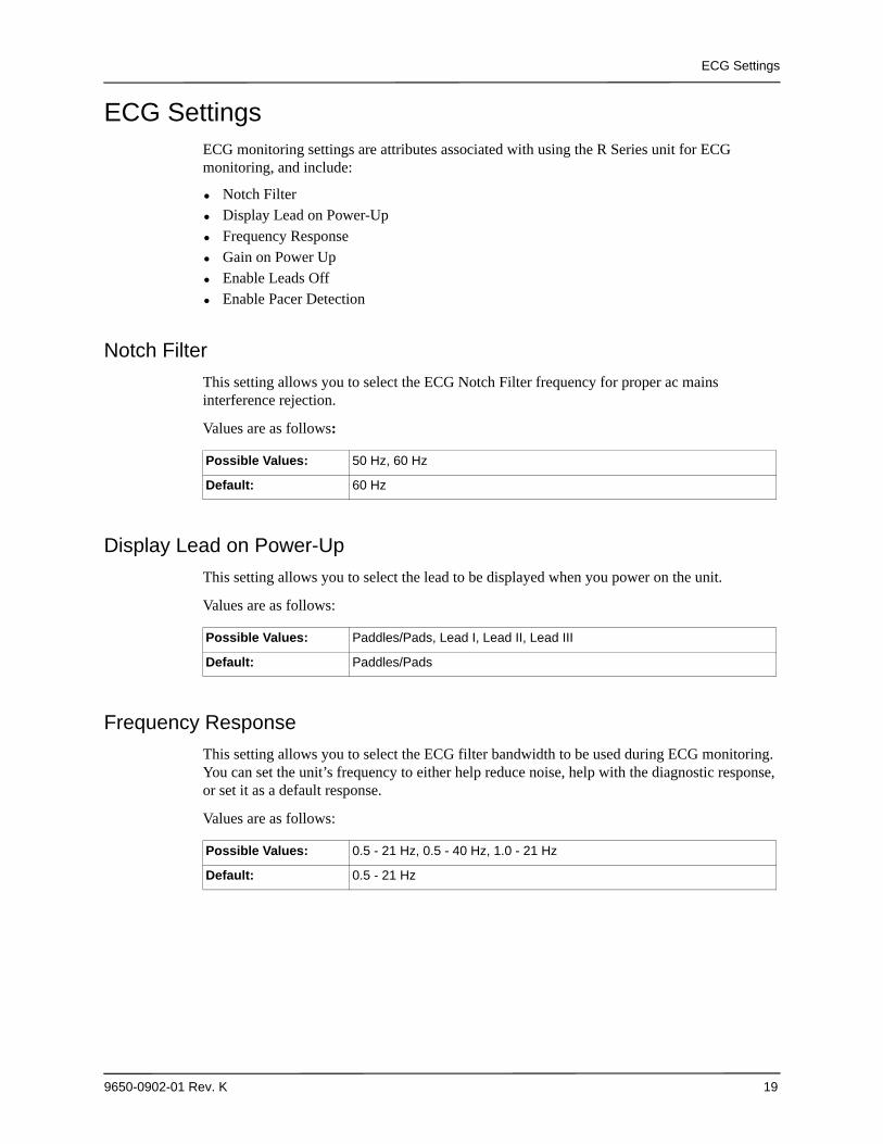
ECG SettingsECG monitoring settings are attributes associated with using the R Series unit for ECG monitoring, and include:
• Notch Filter• Display Lead on Power-Up• Frequency Response• Gain on Power Up• Enable Leads Off• Enable Pacer Detection
Notch Filter
This setting allows you to select the ECG Notch Filter frequency for proper ac mains interference rejection.
Values are as follows:
Display Lead on Power-Up
This setting allows you to select the lead to be displayed when you power on the unit.
Values are as follows:
Frequency Response
This setting allows you to select the ECG filter bandwidth to be used during ECG monitoring. You can set the unit’s frequency to either help reduce noise, help with the diagnostic response, or set it as a default response.
Values are as follows:
Possible Values: 50 Hz, 60 Hz
Default: 60 Hz
Possible Values: Paddles/Pads, Lead I, Lead II, Lead III
Default: Paddles/Pads
Possible Values: 0.5 - 21 Hz, 0.5 - 40 Hz, 1.0 - 21 Hz
Default: 0.5 - 21 Hz
Chapter 2 Configuration Settings
20 9650-0902-01 Rev. K
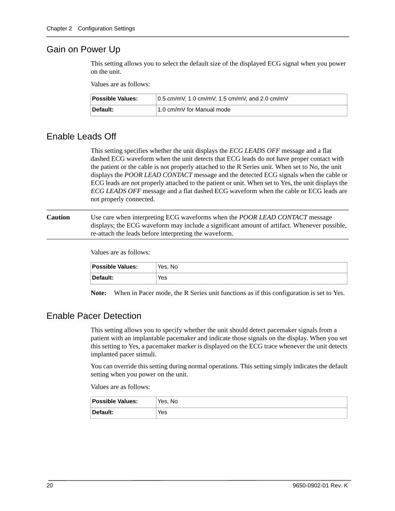
Gain on Power Up
This setting allows you to select the default size of the displayed ECG signal when you power on the unit.
Values are as follows:
Enable Leads Off
This setting specifies whether the unit displays the ECG LEADS OFF message and a flat dashed ECG waveform when the unit detects that ECG leads do not have proper contact with the patient or the cable is not properly attached to the R Series unit. When set to No, the unit displays the POOR LEAD CONTACT message and the detected ECG signals when the cable or ECG leads are not properly attached to the patient or unit. When set to Yes, the unit displays the ECG LEADS OFF message and a flat dashed ECG waveform when the cable or ECG leads are not properly connected.
Caution Use care when interpreting ECG waveforms when the POOR LEAD CONTACT message displays; the ECG waveform may include a significant amount of artifact. Whenever possible, re-attach the leads before interpreting the waveform.
Values are as follows:
Note: When in Pacer mode, the R Series unit functions as if this configuration is set to Yes.
Enable Pacer Detection
This setting allows you to specify whether the unit should detect pacemaker signals from a patient with an implantable pacemaker and indicate those signals on the display. When you set this setting to Yes, a pacemaker marker is displayed on the ECG trace whenever the unit detects implanted pacer stimuli.
You can override this setting during normal operations. This setting simply indicates the default setting when you power on the unit.
Values are as follows:
Possible Values: 0.5 cm/mV, 1.0 cm/mV, 1.5 cm/mV, and 2.0 cm/mV
Default: 1.0 cm/mV for Manual mode
Possible Values: Yes, No
Default: Yes
Possible Values: Yes, No
Default: Yes
Audio Settings
9650-0902-01 Rev. K 21
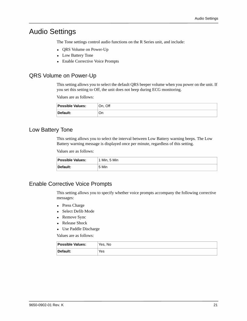
Audio SettingsThe Tone settings control audio functions on the R Series unit, and include:
• QRS Volume on Power-Up• Low Battery Tone• Enable Corrective Voice Prompts
QRS Volume on Power-Up
This setting allows you to select the default QRS beeper volume when you power on the unit. If you set this setting to Off, the unit does not beep during ECG monitoring.
Values are as follows:
Low Battery Tone
This setting allows you to select the interval between Low Battery warning beeps. The Low Battery warning message is displayed once per minute, regardless of this setting.
Values are as follows:
Enable Corrective Voice Prompts
This setting allows you to specify whether voice prompts accompany the following corrective messages:
• Press Charge • Select Defib Mode • Remove Sync • Release Shock • Use Paddle Discharge
Values are as follows:
Possible Values: On, Off
Default: On
Possible Values: 1 Min, 5 Min
Default: 5 Min
Possible Values: Yes, No
Default: Yes
Chapter 2 Configuration Settings
22 9650-0902-01 Rev. K
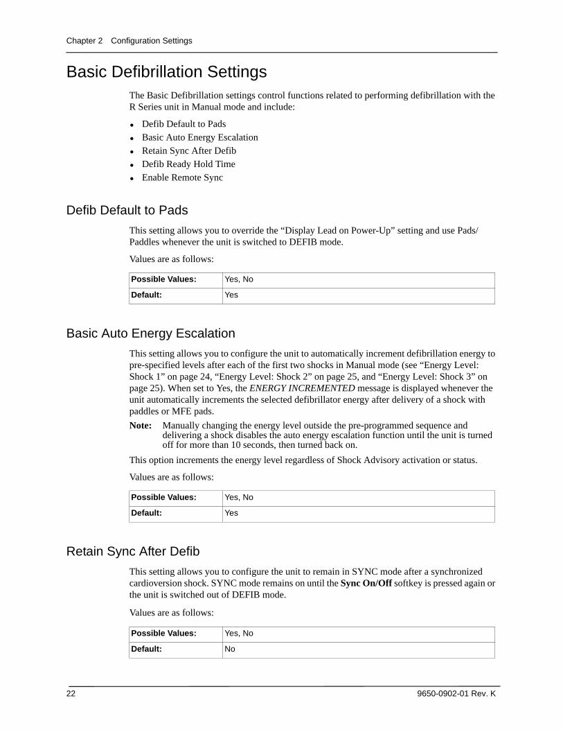
Basic Defibrillation SettingsThe Basic Defibrillation settings control functions related to performing defibrillation with the R Series unit in Manual mode and include:
• Defib Default to Pads• Basic Auto Energy Escalation• Retain Sync After Defib• Defib Ready Hold Time• Enable Remote Sync
Defib Default to Pads
This setting allows you to override the “Display Lead on Power-Up” setting and use Pads/Paddles whenever the unit is switched to DEFIB mode.
Values are as follows:
Basic Auto Energy Escalation
This setting allows you to configure the unit to automatically increment defibrillation energy to pre-specified levels after each of the first two shocks in Manual mode (see “Energy Level: Shock 1” on page 24, “Energy Level: Shock 2” on page 25, and “Energy Level: Shock 3” on page 25). When set to Yes, the ENERGY INCREMENTED message is displayed whenever the unit automatically increments the selected defibrillator energy after delivery of a shock with paddles or MFE pads.
Note: Manually changing the energy level outside the pre-programmed sequence and delivering a shock disables the auto energy escalation function until the unit is turned off for more than 10 seconds, then turned back on.
This option increments the energy level regardless of Shock Advisory activation or status.
Values are as follows:
Retain Sync After Defib
This setting allows you to configure the unit to remain in SYNC mode after a synchronized cardioversion shock. SYNC mode remains on until the Sync On/Off softkey is pressed again or the unit is switched out of DEFIB mode.
Values are as follows:
Possible Values: Yes, No
Default: Yes
Possible Values: Yes, No
Default: Yes
Possible Values: Yes, No
Default: No
Basic Defibrillation Settings
9650-0902-01 Rev. K 23
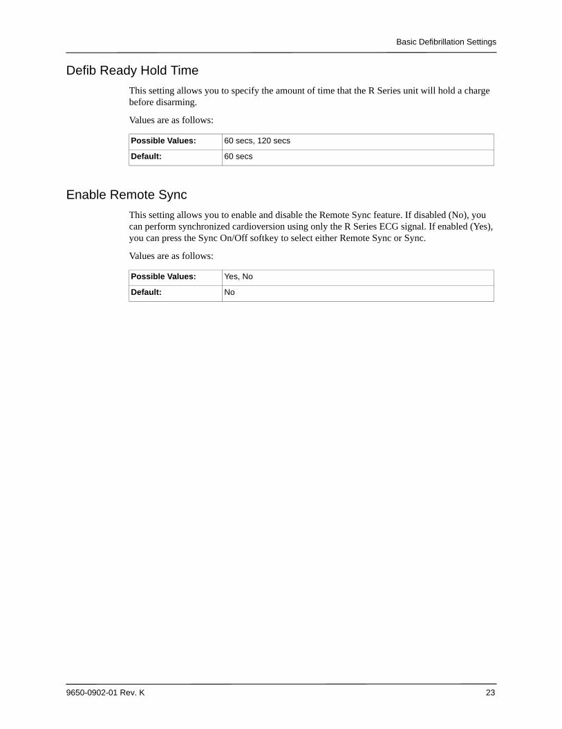
Defib Ready Hold Time
This setting allows you to specify the amount of time that the R Series unit will hold a charge before disarming.
Values are as follows:
Enable Remote Sync
This setting allows you to enable and disable the Remote Sync feature. If disabled (No), you can perform synchronized cardioversion using only the R Series ECG signal. If enabled (Yes), you can press the Sync On/Off softkey to select either Remote Sync or Sync.
Values are as follows:
Possible Values: 60 secs, 120 secs
Default: 60 secs
Possible Values: Yes, No
Default: No
Chapter 2 Configuration Settings
24 9650-0902-01 Rev. K
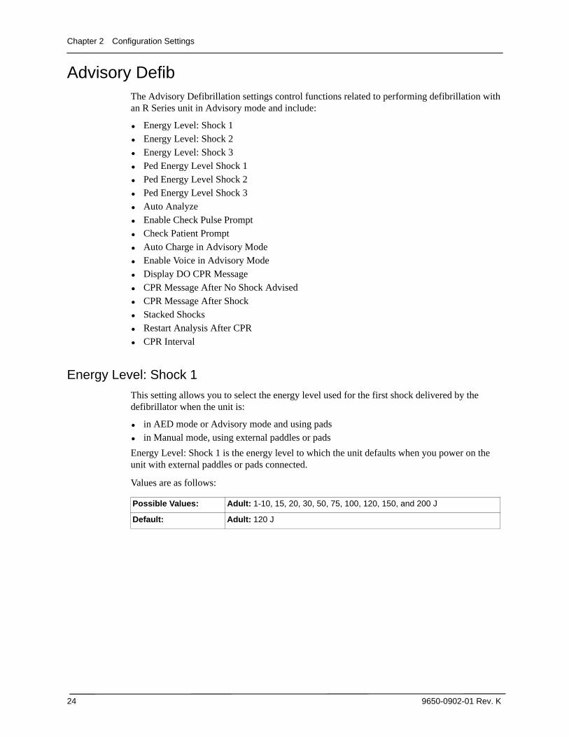
Advisory DefibThe Advisory Defibrillation settings control functions related to performing defibrillation with an R Series unit in Advisory mode and include:
• Energy Level: Shock 1• Energy Level: Shock 2• Energy Level: Shock 3• Ped Energy Level Shock 1• Ped Energy Level Shock 2• Ped Energy Level Shock 3• Auto Analyze• Enable Check Pulse Prompt• Check Patient Prompt• Auto Charge in Advisory Mode• Enable Voice in Advisory Mode• Display DO CPR Message• CPR Message After No Shock Advised• CPR Message After Shock• Stacked Shocks• Restart Analysis After CPR• CPR Interval
Energy Level: Shock 1
This setting allows you to select the energy level used for the first shock delivered by the defibrillator when the unit is:
• in AED mode or Advisory mode and using pads• in Manual mode, using external paddles or pads
Energy Level: Shock 1 is the energy level to which the unit defaults when you power on the unit with external paddles or pads connected.
Values are as follows:
Possible Values: Adult: 1-10, 15, 20, 30, 50, 75, 100, 120, 150, and 200 J
Default: Adult: 120 J
Advisory Defib
9650-0902-01 Rev. K 25
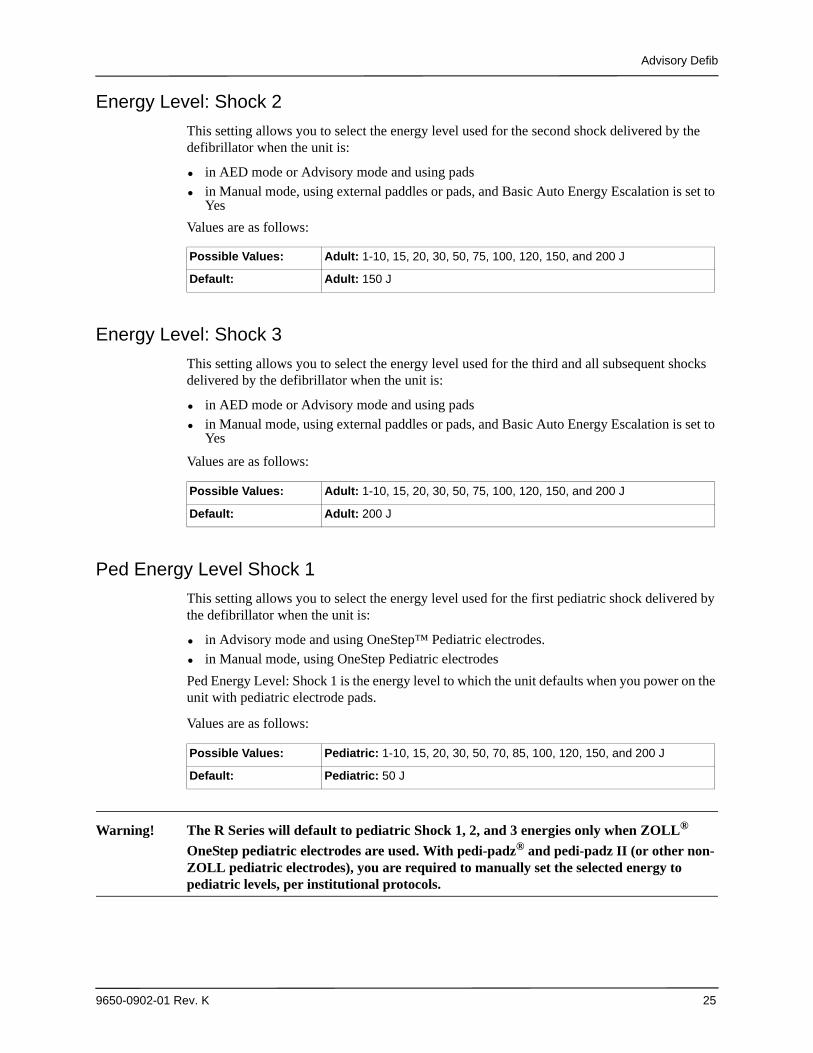
Energy Level: Shock 2
This setting allows you to select the energy level used for the second shock delivered by the defibrillator when the unit is:
• in AED mode or Advisory mode and using pads• in Manual mode, using external paddles or pads, and Basic Auto Energy Escalation is set to
Yes
Values are as follows:
Energy Level: Shock 3
This setting allows you to select the energy level used for the third and all subsequent shocks delivered by the defibrillator when the unit is:
• in AED mode or Advisory mode and using pads• in Manual mode, using external paddles or pads, and Basic Auto Energy Escalation is set to
Yes
Values are as follows:
Ped Energy Level Shock 1
This setting allows you to select the energy level used for the first pediatric shock delivered by the defibrillator when the unit is:
• in Advisory mode and using OneStep™ Pediatric electrodes.• in Manual mode, using OneStep Pediatric electrodes
Ped Energy Level: Shock 1 is the energy level to which the unit defaults when you power on the unit with pediatric electrode pads.
Values are as follows:
Warning! The R Series will default to pediatric Shock 1, 2, and 3 energies only when ZOLL®
OneStep pediatric electrodes are used. With pedi-padz® and pedi-padz II (or other non-ZOLL pediatric electrodes), you are required to manually set the selected energy to pediatric levels, per institutional protocols.
Possible Values: Adult: 1-10, 15, 20, 30, 50, 75, 100, 120, 150, and 200 J
Default: Adult: 150 J
Possible Values: Adult: 1-10, 15, 20, 30, 50, 75, 100, 120, 150, and 200 J
Default: Adult: 200 J
Possible Values: Pediatric: 1-10, 15, 20, 30, 50, 70, 85, 100, 120, 150, and 200 J
Default: Pediatric: 50 J
Chapter 2 Configuration Settings
26 9650-0902-01 Rev. K
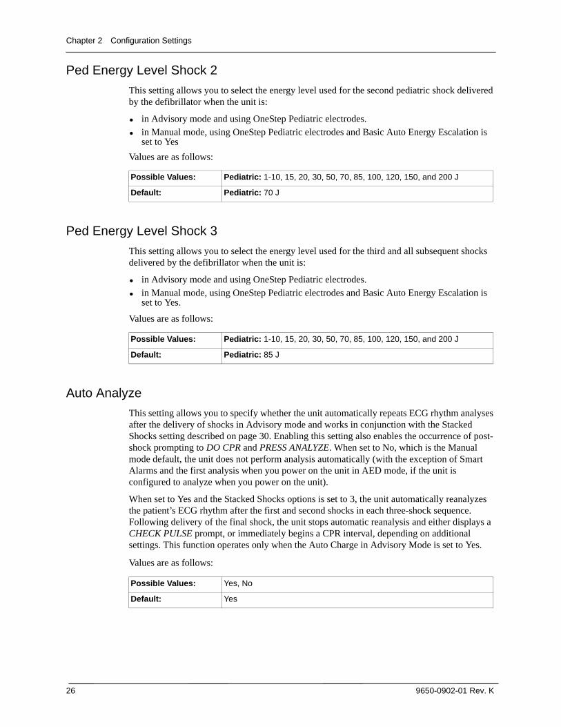
Ped Energy Level Shock 2
This setting allows you to select the energy level used for the second pediatric shock delivered by the defibrillator when the unit is:
• in Advisory mode and using OneStep Pediatric electrodes.• in Manual mode, using OneStep Pediatric electrodes and Basic Auto Energy Escalation is
set to Yes
Values are as follows:
Ped Energy Level Shock 3
This setting allows you to select the energy level used for the third and all subsequent shocks delivered by the defibrillator when the unit is:
• in Advisory mode and using OneStep Pediatric electrodes.• in Manual mode, using OneStep Pediatric electrodes and Basic Auto Energy Escalation is
set to Yes.
Values are as follows:
Auto Analyze
This setting allows you to specify whether the unit automatically repeats ECG rhythm analyses after the delivery of shocks in Advisory mode and works in conjunction with the Stacked Shocks setting described on page 30. Enabling this setting also enables the occurrence of post-shock prompting to DO CPR and PRESS ANALYZE. When set to No, which is the Manual mode default, the unit does not perform analysis automatically (with the exception of Smart Alarms and the first analysis when you power on the unit in AED mode, if the unit is configured to analyze when you power on the unit).
When set to Yes and the Stacked Shocks options is set to 3, the unit automatically reanalyzes the patient’s ECG rhythm after the first and second shocks in each three-shock sequence. Following delivery of the final shock, the unit stops automatic reanalysis and either displays a CHECK PULSE prompt, or immediately begins a CPR interval, depending on additional settings. This function operates only when the Auto Charge in Advisory Mode is set to Yes.
Values are as follows:
Possible Values: Pediatric: 1-10, 15, 20, 30, 50, 70, 85, 100, 120, 150, and 200 J
Default: Pediatric: 70 J
Possible Values: Pediatric: 1-10, 15, 20, 30, 50, 70, 85, 100, 120, 150, and 200 J
Default: Pediatric: 85 J
Possible Values: Yes, No
Default: Yes
Advisory Defib
9650-0902-01 Rev. K 27
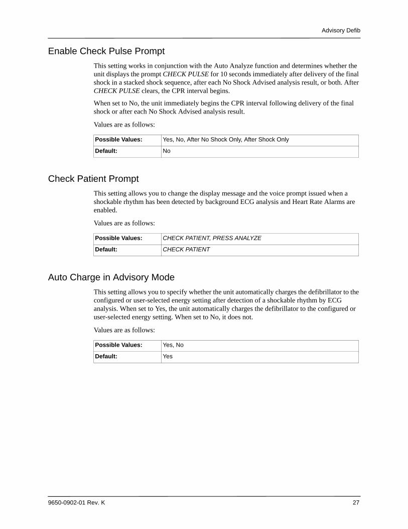
Enable Check Pulse Prompt
This setting works in conjunction with the Auto Analyze function and determines whether the unit displays the prompt CHECK PULSE for 10 seconds immediately after delivery of the final shock in a stacked shock sequence, after each No Shock Advised analysis result, or both. After CHECK PULSE clears, the CPR interval begins.
When set to No, the unit immediately begins the CPR interval following delivery of the final shock or after each No Shock Advised analysis result.
Values are as follows:
Check Patient Prompt
This setting allows you to change the display message and the voice prompt issued when a shockable rhythm has been detected by background ECG analysis and Heart Rate Alarms are enabled.
Values are as follows:
Auto Charge in Advisory Mode
This setting allows you to specify whether the unit automatically charges the defibrillator to the configured or user-selected energy setting after detection of a shockable rhythm by ECG analysis. When set to Yes, the unit automatically charges the defibrillator to the configured or user-selected energy setting. When set to No, it does not.
Values are as follows:
Possible Values: Yes, No, After No Shock Only, After Shock Only
Default: No
Possible Values: CHECK PATIENT, PRESS ANALYZE
Default: CHECK PATIENT
Possible Values: Yes, No
Default: Yes
Chapter 2 Configuration Settings
28 9650-0902-01 Rev. K
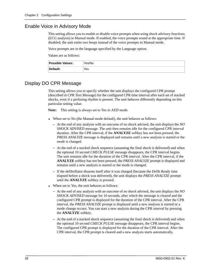
Enable Voice in Advisory Mode
This setting allows you to enable or disable voice prompts when using shock advisory functions (ECG analysis) in Manual mode. If enabled, the voice prompts sound at the appropriate time. If disabled, the unit emits two beeps instead of the voice prompts in Manual mode.
Voice prompts are in the language specified by the Language option.
Values are as follows:
Display DO CPR Message
This setting allows you to specify whether the unit displays the configured CPR prompt (described in CPR Text Message) for the configured CPR time interval after each set of stacked shocks, even if a perfusing rhythm is present. The unit behaves differently depending on this particular setting value.
Note: This setting is always set to Yes in AED mode.
• When set to No (the Manual mode default), the unit behaves as follows:
— At the end of any analysis with an outcome of no shock advised, the unit displays the NO SHOCK ADVISED message. The unit then remains idle for the configured CPR interval duration. After the CPR interval, if the ANALYZE softkey has not been pressed, the PRESS ANALYZE message is displayed and remains until a new analysis is started or the mode is changed.
— At the end of a stacked shock sequence (assuming the final shock is delivered) and when the optional 10 second CHECK PULSE message disappears, the CPR interval begins. The unit remains idle for the duration of the CPR interval. After the CPR interval, if the ANALYZE softkey has not been pressed, the PRESS ANALYZE prompt is displayed and remains until a new analysis is started or the mode is changed.
— If the defibrillator disarms itself after it was charged (because the Defib Ready time elapsed before a shock was delivered), the unit displays the PRESS ANALYZE prompt until the ANALYZE softkey is pressed.
• When set to Yes, the unit behaves as follows:
— At the end of any analysis with an outcome of no shock advised, the unit displays the NO SHOCK ADVISED message for 10 seconds, after which the message is cleared and the configured CPR prompt is displayed for the duration of the CPR interval. After the CPR interval, the PRESS ANALYZE prompt is displayed until a new analysis is started or a mode change occurs. You can start a new analysis during the CPR interval by pressing the ANALYZE softkey.
— At the end of a stacked shock sequence (assuming the final shock is delivered) and when the optional 10 second CHECK PULSE message disappears, the CPR interval begins. The configured CPR prompt is displayed for the duration of the CPR interval. After the CPR interval, the CPR prompt is cleared and a new analysis starts automatically.
Possible Values: Yes/No
Default: Yes
Advisory Defib
9650-0902-01 Rev. K 29
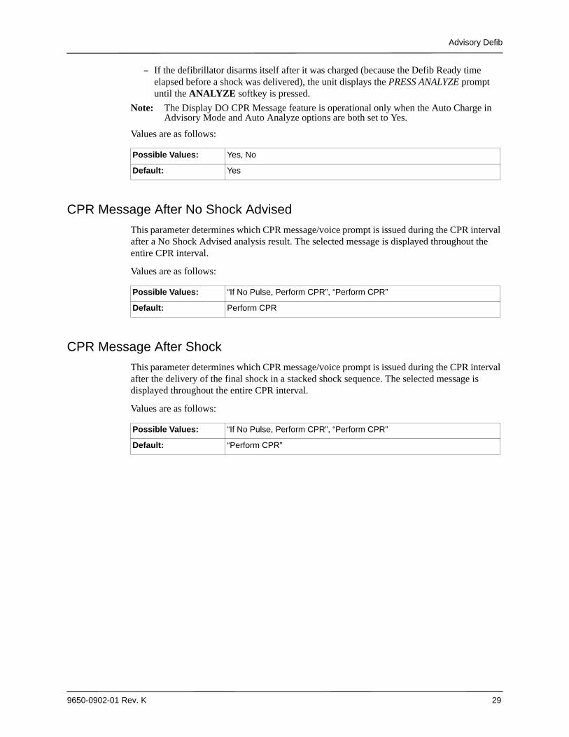
— If the defibrillator disarms itself after it was charged (because the Defib Ready time elapsed before a shock was delivered), the unit displays the PRESS ANALYZE prompt until the ANALYZE softkey is pressed.
Note: The Display DO CPR Message feature is operational only when the Auto Charge in Advisory Mode and Auto Analyze options are both set to Yes.
Values are as follows:
CPR Message After No Shock Advised
This parameter determines which CPR message/voice prompt is issued during the CPR interval after a No Shock Advised analysis result. The selected message is displayed throughout the entire CPR interval.
Values are as follows:
CPR Message After Shock
This parameter determines which CPR message/voice prompt is issued during the CPR interval after the delivery of the final shock in a stacked shock sequence. The selected message is displayed throughout the entire CPR interval.
Values are as follows:
Possible Values: Yes, No
Default: Yes
Possible Values: “If No Pulse, Perform CPR”, “Perform CPR”
Default: Perform CPR
Possible Values: “If No Pulse, Perform CPR”, “Perform CPR”
Default: “Perform CPR”
Chapter 2 Configuration Settings
30 9650-0902-01 Rev. K
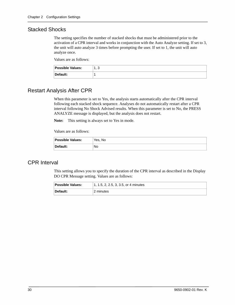
Stacked Shocks
The setting specifies the number of stacked shocks that must be administered prior to the activation of a CPR interval and works in conjunction with the Auto Analyze setting. If set to 3, the unit will auto analyze 3 times before prompting the user. If set to 1, the unit will auto analyze once.
Values are as follows:
Restart Analysis After CPR
When this parameter is set to Yes, the analysis starts automatically after the CPR interval following each stacked shock sequence. Analyses do not automatically restart after a CPR interval following No Shock Advised results. When this parameter is set to No, the PRESS ANALYZE message is displayed, but the analysis does not restart.
Note: This setting is always set to Yes in mode.
Values are as follows:
CPR Interval
This setting allows you to specify the duration of the CPR interval as described in the Display DO CPR Message setting. Values are as follows:
Possible Values: 1, 3
Default: 1
Possible Values: Yes, No
Default: No
Possible Values: 1, 1.5, 2, 2.5, 3, 3.5, or 4 minutes
Default: 2 minutes
CPR Settings
9650-0902-01 Rev. K 31
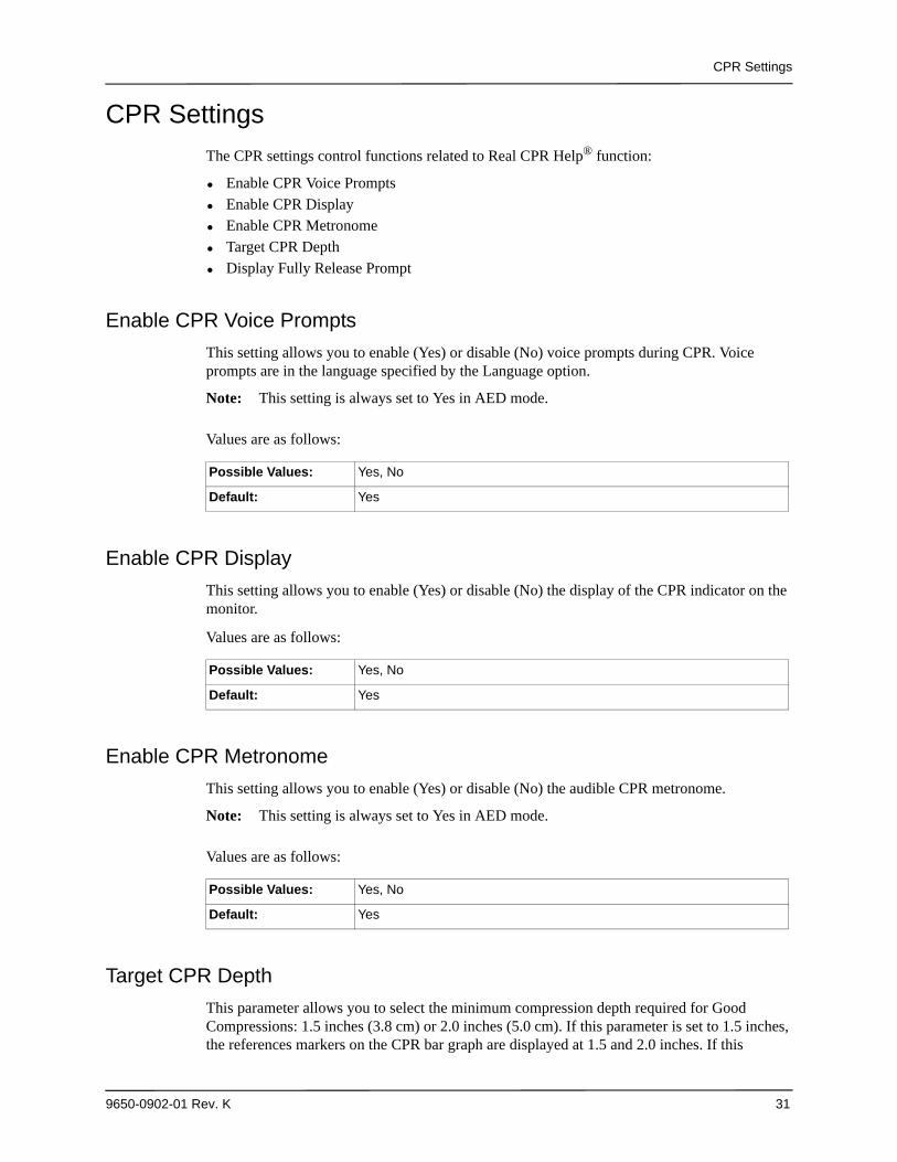
CPR Settings
The CPR settings control functions related to Real CPR Help® function:
• Enable CPR Voice Prompts• Enable CPR Display• Enable CPR Metronome• Target CPR Depth• Display Fully Release Prompt
Enable CPR Voice Prompts
This setting allows you to enable (Yes) or disable (No) voice prompts during CPR. Voice prompts are in the language specified by the Language option.
Note: This setting is always set to Yes in AED mode.
Values are as follows:
Enable CPR Display
This setting allows you to enable (Yes) or disable (No) the display of the CPR indicator on the monitor.
Values are as follows:
Enable CPR Metronome
This setting allows you to enable (Yes) or disable (No) the audible CPR metronome.
Note: This setting is always set to Yes in AED mode.
Values are as follows:
Target CPR Depth
This parameter allows you to select the minimum compression depth required for Good Compressions: 1.5 inches (3.8 cm) or 2.0 inches (5.0 cm). If this parameter is set to 1.5 inches, the references markers on the CPR bar graph are displayed at 1.5 and 2.0 inches. If this
Possible Values: Yes, No
Default: Yes
Possible Values: Yes, No
Default: Yes
Possible Values: Yes, No
Default: Yes
Chapter 2 Configuration Settings
32 9650-0902-01 Rev. K
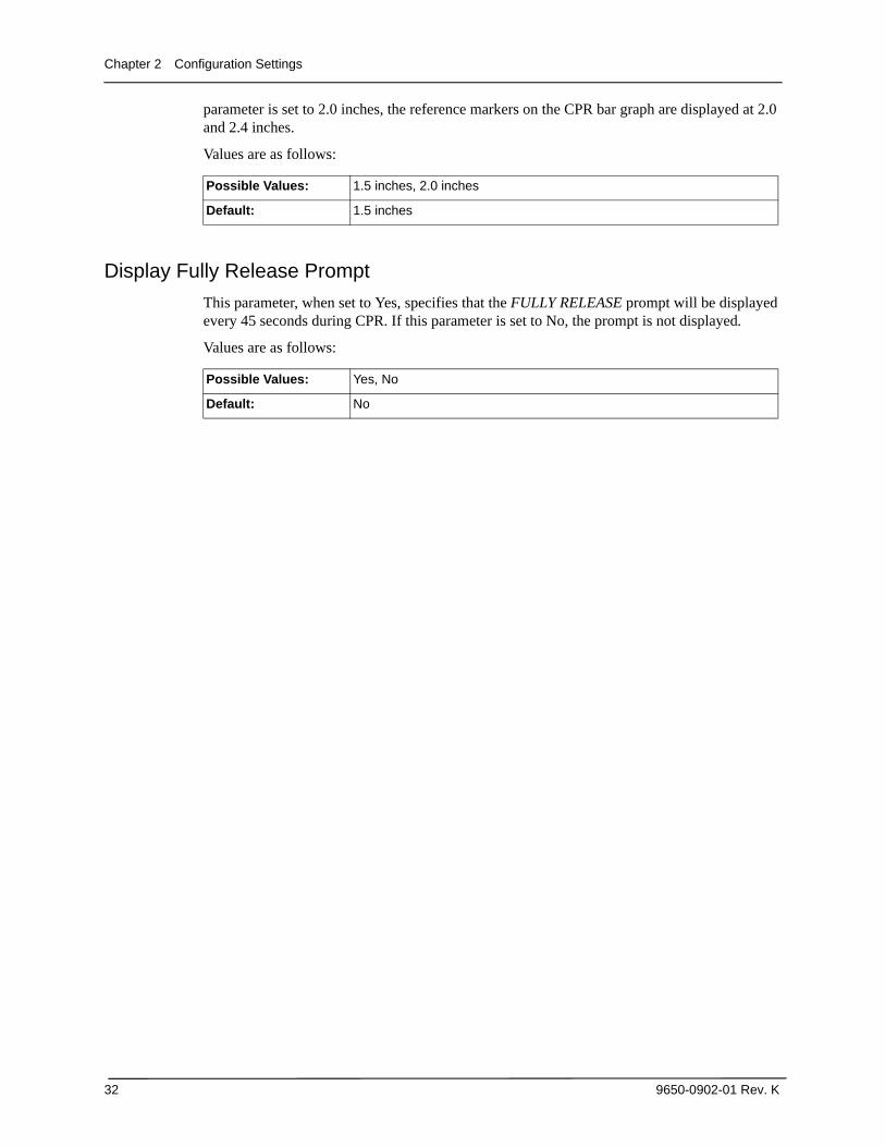
parameter is set to 2.0 inches, the reference markers on the CPR bar graph are displayed at 2.0 and 2.4 inches.
Values are as follows:
Display Fully Release Prompt
This parameter, when set to Yes, specifies that the FULLY RELEASE prompt will be displayed every 45 seconds during CPR. If this parameter is set to No, the prompt is not displayed.
Values are as follows:
Possible Values: 1.5 inches, 2.0 inches
Default: 1.5 inches
Possible Values: Yes, No
Default: No
Pace Settings
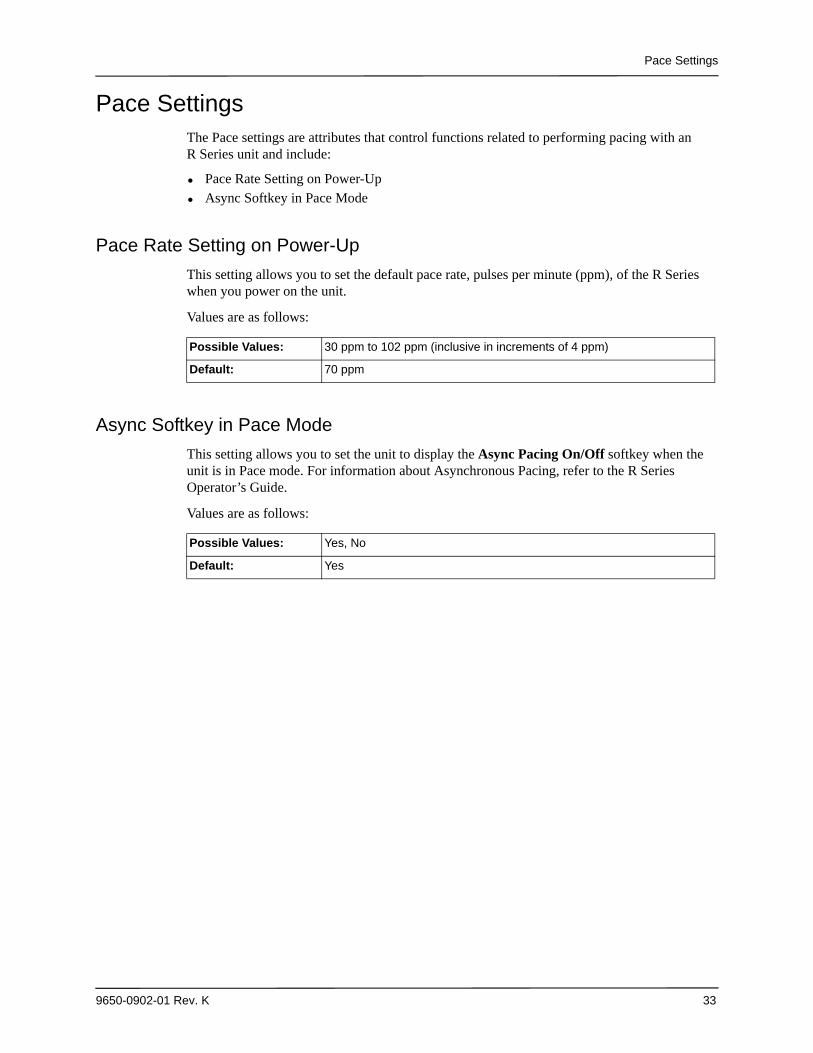
9650-0902-01 Rev. K 33
Pace SettingsThe Pace settings are attributes that control functions related to performing pacing with an R Series unit and include:
• Pace Rate Setting on Power-Up• Async Softkey in Pace Mode
Pace Rate Setting on Power-Up
This setting allows you to set the default pace rate, pulses per minute (ppm), of the R Series when you power on the unit.
Values are as follows:
Async Softkey in Pace Mode
This setting allows you to set the unit to display the Async Pacing On/Off softkey when the unit is in Pace mode. For information about Asynchronous Pacing, refer to the R Series Operator’s Guide.
Values are as follows:
Possible Values: 30 ppm to 102 ppm (inclusive in increments of 4 ppm)
Default: 70 ppm
Possible Values: Yes, No
Default: Yes

Chapter 2 Configuration Settings
34 9650-0902-01 Rev. K
Alarms SettingsAlarm settings are attributes associated with Alarm states and thresholds for the R Series unit and include:
• Alarm Limits at Power Up• Alarms Active at Power Up
Alarms Settings
9650-0902-01 Rev. K 35
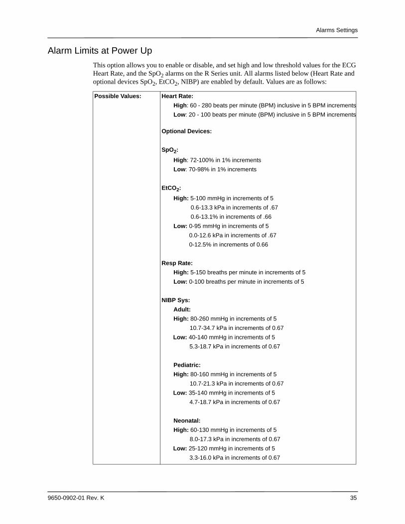
Alarm Limits at Power Up
This option allows you to enable or disable, and set high and low threshold values for the ECG Heart Rate, and the SpO2 alarms on the R Series unit. All alarms listed below (Heart Rate and optional devices SpO2, EtCO2, NIBP) are enabled by default. Values are as follows:
Possible Values: Heart Rate:
High: 60 - 280 beats per minute (BPM) inclusive in 5 BPM increments
Low: 20 - 100 beats per minute (BPM) inclusive in 5 BPM increments
Optional Devices:
SpO2:
High: 72-100% in 1% increments
Low: 70-98% in 1% increments
EtCO2:
High: 5-100 mmHg in increments of 5
0.6-13.3 kPa in increments of .67
0.6-13.1% in increments of .66
Low: 0-95 mmHg in increments of 5
0.0-12.6 kPa in increments of .67
0-12.5% in increments of 0.66
Resp Rate:
High: 5-150 breaths per minute in increments of 5
Low: 0-100 breaths per minute in increments of 5
NIBP Sys:
Adult:
High: 80-260 mmHg in increments of 5
10.7-34.7 kPa in increments of 0.67
Low: 40-140 mmHg in increments of 5
5.3-18.7 kPa in increments of 0.67
Pediatric:
High: 80-160 mmHg in increments of 5
10.7-21.3 kPa in increments of 0.67
Low: 35-140 mmHg in increments of 5
4.7-18.7 kPa in increments of 0.67
Neonatal:
High: 60-130 mmHg in increments of 5
8.0-17.3 kPa in increments of 0.67
Low: 25-120 mmHg in increments of 5
3.3-16.0 kPa in increments of 0.67
Chapter 2 Configuration Settings
36 9650-0902-01 Rev. K
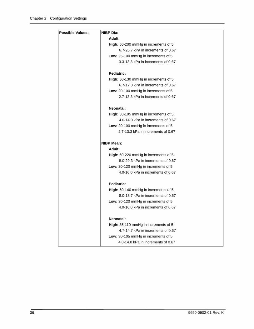
Possible Values: NIBP Dia:
Adult:
High: 50-200 mmHg in increments of 5
6.7-26.7 kPa in increments of 0.67
Low: 25-100 mmHg in increments of 5
3.3-13.3 kPa in increments of 0.67
Pediatric:
High: 50-130 mmHg in increments of 5
6.7-17.3 kPa in increments of 0.67
Low: 20-100 mmHg in increments of 5
2.7-13.3 kPa in increments of 0.67
Neonatal:
High: 30-105 mmHg in increments of 5
4.0-14.0 kPa in increments of 0.67
Low: 20-100 mmHg in increments of 5
2.7-13.3 kPa in increments of 0.67
NIBP Mean:
Adult:
High: 60-220 mmHg in increments of 5
8.0-29.3 kPa in increments of 0.67
Low: 30-120 mmHg in increments of 5
4.0-16.0 kPa in increments of 0.67
Pediatric:
High: 60-140 mmHg in increments of 5
8.0-18.7 kPa in increments of 0.67
Low: 30-120 mmHg in increments of 5
4.0-16.0 kPa in increments of 0.67
Neonatal:
High: 35-110 mmHg in increments of 5
4.7-14.7 kPa in increments of 0.67
Low: 30-105 mmHg in increments of 5
4.0-14.0 kPa in increments of 0.67
Alarms Settings
9650-0902-01 Rev. K 37
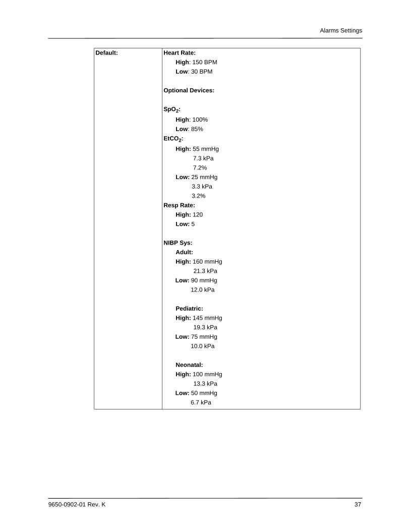
Default: Heart Rate:
High: 150 BPM
Low: 30 BPM
Optional Devices:
SpO2:
High: 100%
Low: 85%
EtCO2:
High: 55 mmHg
7.3 kPa
7.2%
Low: 25 mmHg
3.3 kPa
3.2%
Resp Rate:
High: 120
Low: 5
NIBP Sys:
Adult:
High: 160 mmHg
21.3 kPa
Low: 90 mmHg
12.0 kPa
Pediatric:
High: 145 mmHg
19.3 kPa
Low: 75 mmHg
10.0 kPa
Neonatal:
High: 100 mmHg
13.3 kPa
Low: 50 mmHg
6.7 kPa
Chapter 2 Configuration Settings
38 9650-0902-01 Rev. K
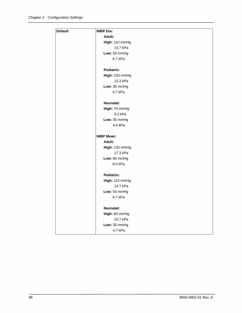
Default NIBP Dia:
Adult:
High: 110 mmHg
14.7 kPa
Low: 50 mmHg
6.7 kPa
Pediatric:
High: 100 mmHg
13.3 kPa
Low: 35 mmHg
4.7 kPa
Neonatal:
High: 70 mmHg
9.3 kPa
Low: 30 mmHg
4.0 kPa
NIBP Mean:
Adult:
High: 130 mmHg
17.3 kPa
Low: 60 mmHg
8.0 kPa
Pediatric:
High: 110 mmHg
14.7 kPa
Low: 50 mmHg
6.7 kPa
Neonatal:
High: 80 mmHg
10.7 kPa
Low: 35 mmHg
4.7 kPa
Alarms Settings
9650-0902-01 Rev. K 39
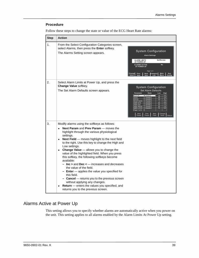
Procedure
Follow these steps to change the state or value of the ECG Heart Rate alarms:
Alarms Active at Power Up
This setting allows you to specify whether alarms are automatically active when you power on the unit. This setting applies to all alarms enabled by the Alarm Limits At Power Up setting.
Step Action
1. From the Select Configuration Categories screen, select Alarms, then press the Enter softkey.
The Alarms Setting screen appears.
2. Select Alarm Limits at Power Up, and press the Change Value softkey.
The Set Alarm Defaults screen appears.
3. Modify alarms using the softkeys as follows:
• Next Param and Prev Param — moves the highlight through the various physiological settings.
• Next Field — moves highlight to the next field to the right. Use this key to change the High and Low settings.
• Change Value — allows you to change the value of the highlighted field. When you press this softkey, the following softkeys become available:— Inc > and Dec < — increases and decreases
the value of the field.— Enter — applies the value you specified for
this field.— Cancel — returns you to the previous screen
without applying any changes.• Return — enters the values you specified, and
returns you to the previous screen.
NextItem
PrevItem
System Configuration
Alarm Settings
Set/Review
MainMenu
ExitConfig
CategoryList
ChangeValue
Page 1 of 1
NoALARMS ACTIVE AT POWER UP
ALARM LIMITSAT POWER UP
Set/Review
ChangeValue
Return
System Configuration
Set Alarm Defaults
Parameter State Low High
30 150 ECG HR ENABLE
Next
Param
Prev
Param
NextField
85 100ENABLESpO225 55ENABLEEtCO25 120ENABLERESP RATE
90 160ENABLENIBP SYS50 110ENABLENIBP DIA60 130ENABLENIBP MEAN75 145ENABLENIBP p SYS
Page 1 of 2
Chapter 2 Configuration Settings
40 9650-0902-01 Rev. K
Values are as follows:
Display SettingsThe Display settings are attributes that control what and how things appear on the R Series monitor and include:
• Display Time• Select Trace 2 At Power Up• Select Trace 3 At Power Up• ECG Color• SpO2 Color• CPR Color• EtCO2 Color• NIBP Color• SPO2 at Power Up
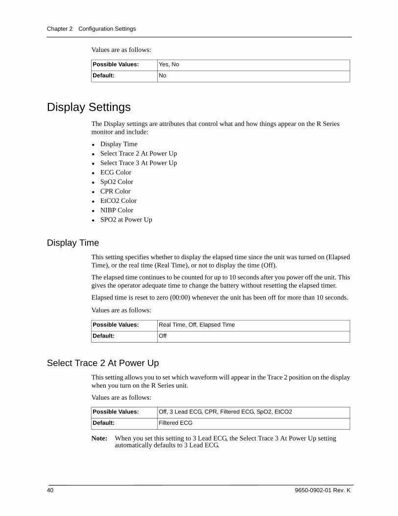
Display Time
This setting specifies whether to display the elapsed time since the unit was turned on (Elapsed Time), or the real time (Real Time), or not to display the time (Off).
The elapsed time continues to be counted for up to 10 seconds after you power off the unit. This gives the operator adequate time to change the battery without resetting the elapsed timer.
Elapsed time is reset to zero (00:00) whenever the unit has been off for more than 10 seconds.
Values are as follows:
Select Trace 2 At Power Up
This setting allows you to set which waveform will appear in the Trace 2 position on the display when you turn on the R Series unit.
Values are as follows:
Note: When you set this setting to 3 Lead ECG, the Select Trace 3 At Power Up setting automatically defaults to 3 Lead ECG.
Possible Values: Yes, No
Default: No
Possible Values: Real Time, Off, Elapsed Time
Default: Off
Possible Values: Off, 3 Lead ECG, CPR, Filtered ECG, SpO2, EtCO2
Default: Filtered ECG
Display Settings
9650-0902-01 Rev. K 41
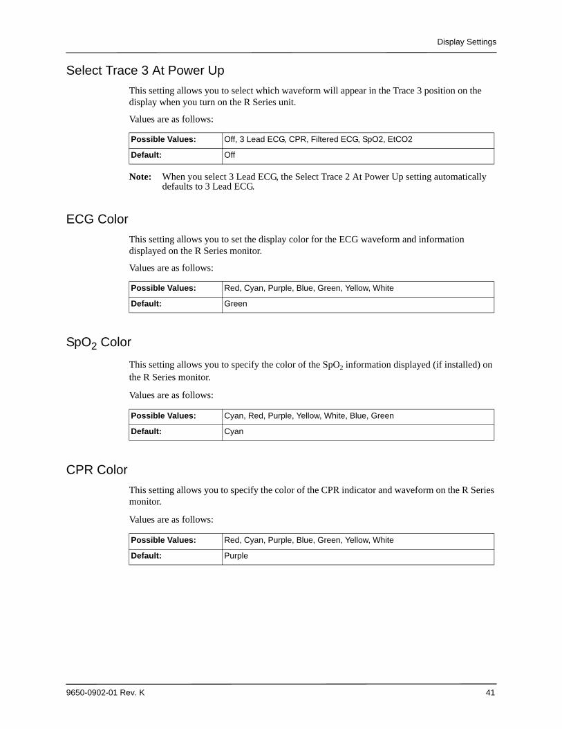
Select Trace 3 At Power Up
This setting allows you to select which waveform will appear in the Trace 3 position on the display when you turn on the R Series unit.
Values are as follows:
Note: When you select 3 Lead ECG, the Select Trace 2 At Power Up setting automatically defaults to 3 Lead ECG.
ECG Color
This setting allows you to set the display color for the ECG waveform and information displayed on the R Series monitor.
Values are as follows:
SpO2 Color
This setting allows you to specify the color of the SpO2 information displayed (if installed) on the R Series monitor.
Values are as follows:
CPR Color
This setting allows you to specify the color of the CPR indicator and waveform on the R Series monitor.
Values are as follows:
Possible Values: Off, 3 Lead ECG, CPR, Filtered ECG, SpO2, EtCO2
Default: Off
Possible Values: Red, Cyan, Purple, Blue, Green, Yellow, White
Default: Green
Possible Values: Cyan, Red, Purple, Yellow, White, Blue, Green
Default: Cyan
Possible Values: Red, Cyan, Purple, Blue, Green, Yellow, White
Default: Purple
Chapter 2 Configuration Settings
42 9650-0902-01 Rev. K
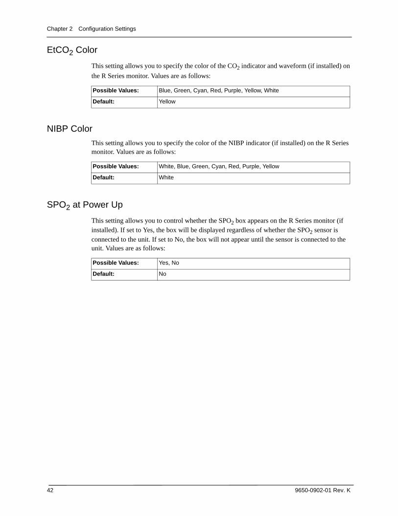
EtCO2 Color
This setting allows you to specify the color of the CO2 indicator and waveform (if installed) on
the R Series monitor. Values are as follows:
NIBP Color
This setting allows you to specify the color of the NIBP indicator (if installed) on the R Series monitor. Values are as follows:
SPO2 at Power Up
This setting allows you to control whether the SPO2 box appears on the R Series monitor (if installed). If set to Yes, the box will be displayed regardless of whether the SPO2 sensor is connected to the unit. If set to No, the box will not appear until the sensor is connected to the unit. Values are as follows:
Possible Values: Blue, Green, Cyan, Red, Purple, Yellow, White
Default: Yellow
Possible Values: White, Blue, Green, Cyan, Red, Purple, Yellow
Default: White
Possible Values: Yes, No
Default: No
NIBP Settings (Optional)
9650-0902-01 Rev. K 43
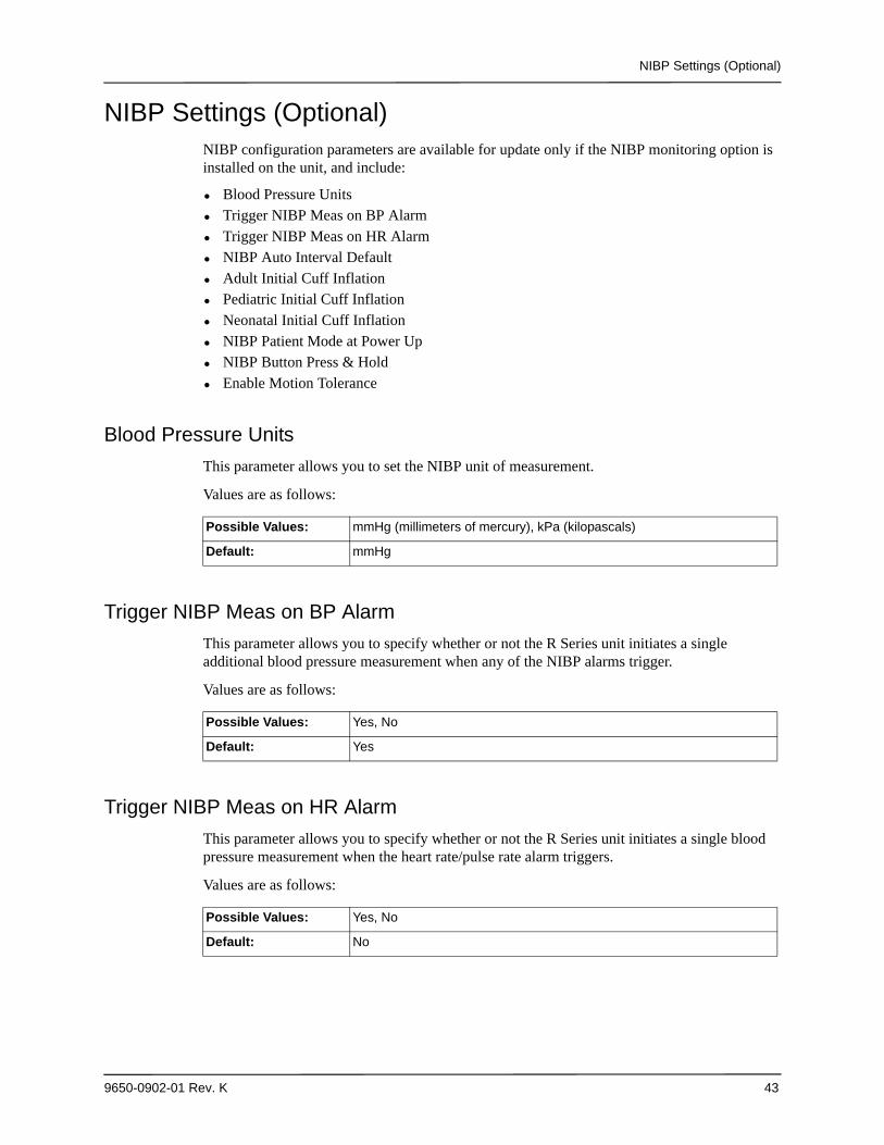
NIBP Settings (Optional)NIBP configuration parameters are available for update only if the NIBP monitoring option is installed on the unit, and include:
• Blood Pressure Units• Trigger NIBP Meas on BP Alarm• Trigger NIBP Meas on HR Alarm• NIBP Auto Interval Default• Adult Initial Cuff Inflation• Pediatric Initial Cuff Inflation• Neonatal Initial Cuff Inflation• NIBP Patient Mode at Power Up• NIBP Button Press & Hold• Enable Motion Tolerance
Blood Pressure Units
This parameter allows you to set the NIBP unit of measurement.
Values are as follows:
Trigger NIBP Meas on BP Alarm
This parameter allows you to specify whether or not the R Series unit initiates a single additional blood pressure measurement when any of the NIBP alarms trigger.
Values are as follows:
Trigger NIBP Meas on HR Alarm
This parameter allows you to specify whether or not the R Series unit initiates a single blood pressure measurement when the heart rate/pulse rate alarm triggers.
Values are as follows:
Possible Values: mmHg (millimeters of mercury), kPa (kilopascals)
Default: mmHg
Possible Values: Yes, No
Default: Yes
Possible Values: Yes, No
Default: No
Chapter 2 Configuration Settings
44 9650-0902-01 Rev. K
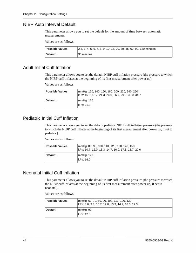
NIBP Auto Interval Default
This parameter allows you to set the default for the amount of time between automatic measurements.
Values are as follows:
Adult Initial Cuff Inflation
This parameter allows you to set the default NIBP cuff inflation pressure (the pressure to which the NIBP cuff inflates at the beginning of its first measurement after power up).
Values are as follows:
Pediatric Initial Cuff Inflation
This parameter allows you to set the default pediatric NIBP cuff inflation pressure (the pressure to which the NIBP cuff inflates at the beginning of its first measurement after power up, if set to pediatric).
Values are as follows:
Neonatal Initial Cuff Inflation
This parameter allows you to set the default NIBP cuff inflation pressure (the pressure to which the NIBP cuff inflates at the beginning of its first measurement after power up, if set to neonatal).
Values are as follows:
Possible Values: 2.5, 3, 4, 5, 6, 7, 8, 9, 10, 15, 20, 30, 45, 60, 90, 120 minutes
Default: 30 minutes
Possible Values: mmHg: 120, 140, 160, 180, 200, 220, 240, 260 kPa: 16.0, 18.7, 21.3, 24.0, 26.7, 29.3, 32.0, 34.7
Default: mmHg: 160
kPa: 21.3
Possible Values: mmHg: 80, 90, 100, 110, 120, 130, 140, 150kPa: 10.7, 12.0, 13.3, 14.7, 16.0, 17.3, 18.7, 20.0
Default: mmHg: 120
kPa: 16.0
Possible Values: mmHg: 60, 70, 80, 90, 100, 110, 120, 130kPa: 8.0, 9.3, 10.7, 12.0, 13.3, 14.7, 16.0, 17.3
Default: mmHg: 90
kPa: 12.0
NIBP Settings (Optional)
9650-0902-01 Rev. K 45
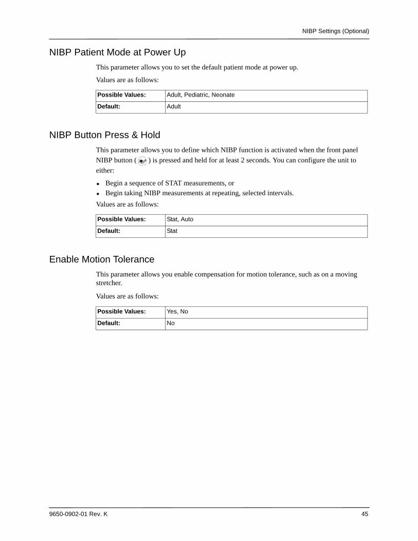
NIBP Patient Mode at Power Up
This parameter allows you to set the default patient mode at power up.
Values are as follows:
NIBP Button Press & Hold
This parameter allows you to define which NIBP function is activated when the front panel
NIBP button ( ) is pressed and held for at least 2 seconds. You can configure the unit to
either:
• Begin a sequence of STAT measurements, or• Begin taking NIBP measurements at repeating, selected intervals.
Values are as follows:
Enable Motion Tolerance
This parameter allows you enable compensation for motion tolerance, such as on a moving stretcher.
Values are as follows:
Possible Values: Adult, Pediatric, Neonate
Default: Adult
Possible Values: Stat, Auto
Default: Stat
Possible Values: Yes, No
Default: No
Chapter 2 Configuration Settings
46 9650-0902-01 Rev. K
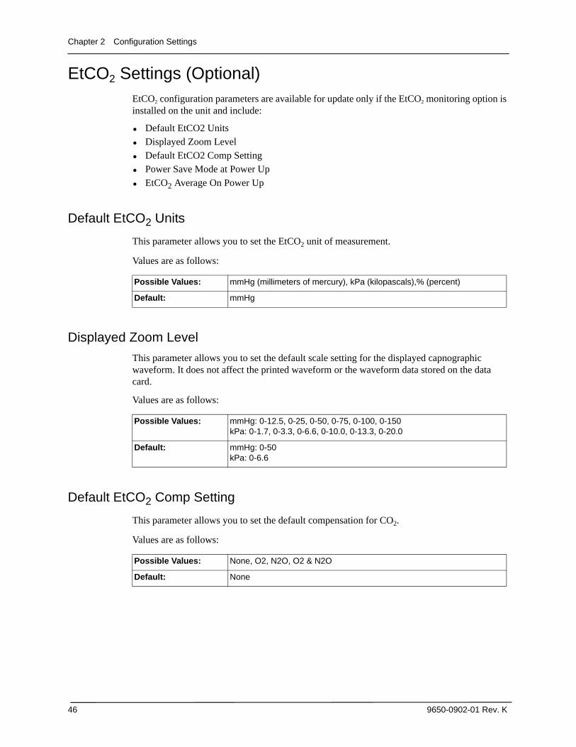
EtCO2 Settings (Optional)EtCO2 configuration parameters are available for update only if the EtCO2 monitoring option is installed on the unit and include:
• Default EtCO2 Units• Displayed Zoom Level• Default EtCO2 Comp Setting• Power Save Mode at Power Up• EtCO2 Average On Power Up
Default EtCO2 Units
This parameter allows you to set the EtCO2 unit of measurement.
Values are as follows:
Displayed Zoom Level
This parameter allows you to set the default scale setting for the displayed capnographic waveform. It does not affect the printed waveform or the waveform data stored on the data card.
Values are as follows:
Default EtCO2 Comp Setting
This parameter allows you to set the default compensation for CO2.
Values are as follows:
Possible Values: mmHg (millimeters of mercury), kPa (kilopascals),% (percent)
Default: mmHg
Possible Values: mmHg: 0-12.5, 0-25, 0-50, 0-75, 0-100, 0-150kPa: 0-1.7, 0-3.3, 0-6.6, 0-10.0, 0-13.3, 0-20.0
Default: mmHg: 0-50kPa: 0-6.6
Possible Values: None, O2, N2O, O2 & N2O
Default: None
EtCO2 Settings (Optional)
9650-0902-01 Rev. K 47
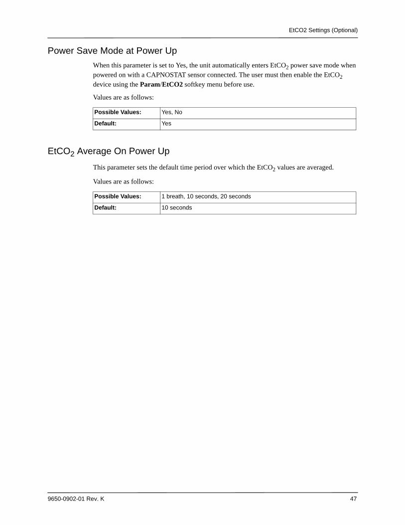
Power Save Mode at Power Up
When this parameter is set to Yes, the unit automatically enters EtCO2 power save mode when powered on with a CAPNOSTAT sensor connected. The user must then enable the EtCO2 device using the Param/EtCO2 softkey menu before use.
Values are as follows:
EtCO2 Average On Power Up
This parameter sets the default time period over which the EtCO2 values are averaged.
Values are as follows:
Possible Values: Yes, No
Default: Yes
Possible Values: 1 breath, 10 seconds, 20 seconds
Default: 10 seconds
Chapter 2 Configuration Settings
48 9650-0902-01 Rev. K
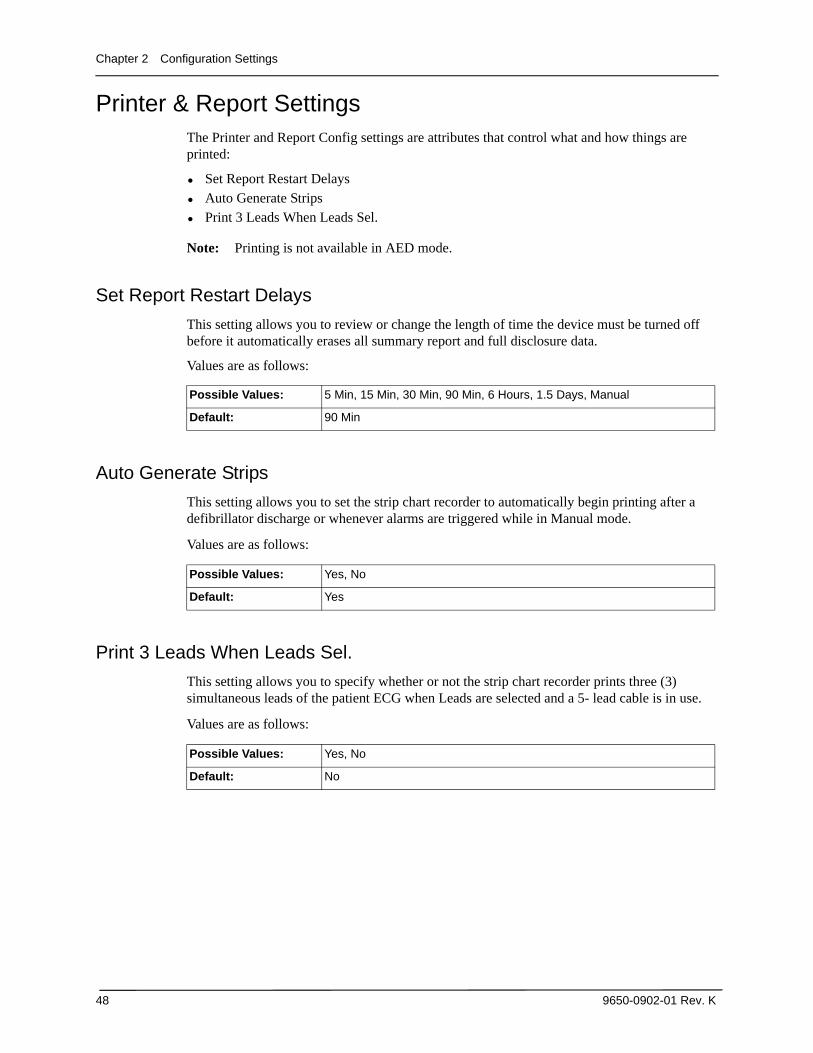
Printer & Report SettingsThe Printer and Report Config settings are attributes that control what and how things are printed:
• Set Report Restart Delays• Auto Generate Strips• Print 3 Leads When Leads Sel.
Note: Printing is not available in AED mode.
Set Report Restart Delays
This setting allows you to review or change the length of time the device must be turned off before it automatically erases all summary report and full disclosure data.
Values are as follows:
Auto Generate Strips
This setting allows you to set the strip chart recorder to automatically begin printing after a defibrillator discharge or whenever alarms are triggered while in Manual mode.
Values are as follows:
Print 3 Leads When Leads Sel.
This setting allows you to specify whether or not the strip chart recorder prints three (3) simultaneous leads of the patient ECG when Leads are selected and a 5- lead cable is in use.
Values are as follows:
Possible Values: 5 Min, 15 Min, 30 Min, 90 Min, 6 Hours, 1.5 Days, Manual
Default: 90 Min
Possible Values: Yes, No
Default: Yes
Possible Values: Yes, No
Default: No
Readiness Test Settings
9650-0902-01 Rev. K 49
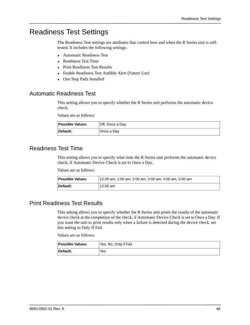
Readiness Test SettingsThe Readiness Test settings are attributes that control how and when the R Series unit is self-tested. It includes the following settings:
• Automatic Readiness Test• Readiness Test Time• Print Readiness Test Results• Enable Readiness Test Audible Alert (Future Use)• One Step Padz Installed
Automatic Readiness Test
This setting allows you to specify whether the R Series unit performs the automatic device check.
Values are as follows:
Readiness Test Time
This setting allows you to specify what time the R Series unit performs the automatic device check, if Automatic Device Check is set to Once a Day.
Values are as follows:
Print Readiness Test Results
This setting allows you to specify whether the R Series unit prints the results of the automatic device check at the completion of the check, if Automatic Device Check is set to Once a Day. If you want the unit to print results only when a failure is detected during the device check, set this setting to Only If Fail.
Values are as follows:
Possible Values: Off, Once a Day
Default: Once a Day
Possible Values: 12:00 am, 1:00 am, 2:00 am, 3:00 am, 4:00 am, 5:00 am
Default: 12:00 am
Possible Values: Yes, No, Only if Fail
Default: Yes
Chapter 2 Configuration Settings
50 9650-0902-01 Rev. K
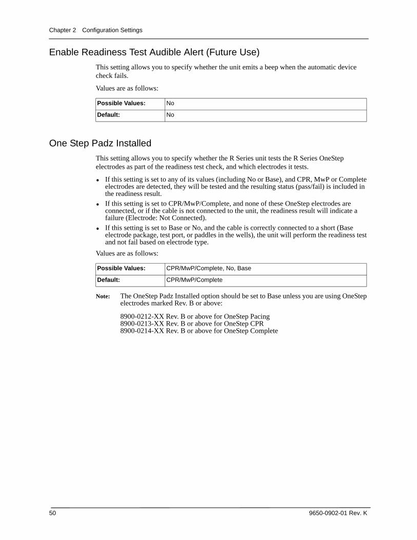
Enable Readiness Test Audible Alert (Future Use)
This setting allows you to specify whether the unit emits a beep when the automatic device check fails.
Values are as follows:
One Step Padz Installed
This setting allows you to specify whether the R Series unit tests the R Series OneStep electrodes as part of the readiness test check, and which electrodes it tests.
• If this setting is set to any of its values (including No or Base), and CPR, MwP or Complete electrodes are detected, they will be tested and the resulting status (pass/fail) is included in the readiness result.
• If this setting is set to CPR/MwP/Complete, and none of these OneStep electrodes are connected, or if the cable is not connected to the unit, the readiness result will indicate a failure (Electrode: Not Connected).
• If this setting is set to Base or No, and the cable is correctly connected to a short (Base electrode package, test port, or paddles in the wells), the unit will perform the readiness test and not fail based on electrode type.
Values are as follows:
Note: The OneStep Padz Installed option should be set to Base unless you are using OneStep electrodes marked Rev. B or above:
8900-0212-XX Rev. B or above for OneStep Pacing8900-0213-XX Rev. B or above for OneStep CPR8900-0214-XX Rev. B or above for OneStep Complete
Possible Values: No
Default: No
Possible Values: CPR/MwP/Complete, No, Base
Default: CPR/MwP/Complete
AED Mode
9650-0902-01 Rev. K 51
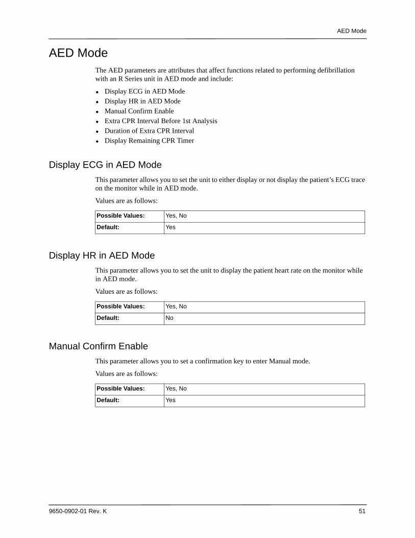
AED ModeThe AED parameters are attributes that affect functions related to performing defibrillation with an R Series unit in AED mode and include:
• Display ECG in AED Mode• Display HR in AED Mode• Manual Confirm Enable• Extra CPR Interval Before 1st Analysis• Duration of Extra CPR Interval• Display Remaining CPR Timer
Display ECG in AED Mode
This parameter allows you to set the unit to either display or not display the patient’s ECG trace on the monitor while in AED mode.
Values are as follows:
Display HR in AED Mode
This parameter allows you to set the unit to display the patient heart rate on the monitor while in AED mode.
Values are as follows:
Manual Confirm Enable
This parameter allows you to set a confirmation key to enter Manual mode.
Values are as follows:
Possible Values: Yes, No
Default: Yes
Possible Values: Yes, No
Default: No
Possible Values: Yes, No
Default: Yes
Chapter 2 Configuration Settings
52 9650-0902-01 Rev. K
Extra CPR Interval Before 1st Analysis
This parameter pertains only to AED mode.
When this parameter is set to No (default), and the unit detects a pad connection upon power- on, it automatically starts an ECG analysis. If the unit is powered on with no pads connected, the unit displays the ATTACH PADS prompt until pads are connected. Once pads are connected, the unit automatically starts an ECG analysis.
When this parameter is set to Yes, the unit displays the prompts: CHECK PULSE for 10 seconds, then IF NO PULSE, PERFORM CPR for the configured Extra CPR interval at power on. At the end of the CPR period, if the unit does not detect a pads connection, it displays the prompt ATTACH PADS until pads are connected. If a pads connection is detected, the unit automatically starts an ECG analysis. You can start an ECG analysis during the CPR interval by pressing the ANALYZE softkey.
Values are as follows:
Duration of Extra CPR Interval
This parameter allows you to specify the duration of the extra CPR interval (see previous entry). It has no effect if “Extra CPR Interval Before 1st Analysis” is set to No.
Values are as follows:
Display Remaining CPR Timer
This parameter allows you to specify whether to display remaining CPR interval during CPR.
Values are as follows:
Possible Values: Yes, No
Default: No
Possible Values: 0.5, 1, 1.5, 2, 2.5, 3, 3.5 or 4 minutes
Default: 2 minutes
Possible Values: Yes, No
Default: Yes
Wi-Fi Settings (Optional)
9650-0902-01 Rev. K 53
Wi-Fi Settings (Optional)The Wi-Fi settings are attributes that control how files are transferred and the security method that is used.
Full Disclosure Transfer Mode
This setting allows you to determine the following:
• whether full disclosure file transfers are supported• whether the Send Report softkey is displayed
Values are as follows:
Defib History Transfer Mode
This setting allows you to specify whether device check files and activity log files will be transmitted, and determines whether Defib History to Wi-Fi softkey is displayed.
Values are as follows:
Infrastructure Mode Options
DHCP/Static IP
This setting allows you to either manually set the static IP address or retrieve the IP address from a DHCP server.
Note: If this setting is set to Static IP, you need to set the following settings: Gateway IP Address, Subnet Mask, and DNS IP Address.
Values are as follows:
Possible Values: Server, None
Default: Server
Possible Values: Both, None, Manual, Automatic
Default: None
Possible Values: Static IP, DHCP
Default: DHCP

Chapter 2 Configuration Settings
54 9650-0902-01 Rev. K
Local IP Address
This setting allows you to specify the defibrillator’s IP address used in the static configuration.
Note: This setting is available only when DHCP/Static IP is set to Static IP.
Values are as follows:
Procedure
Follow these steps to set up a Local IP Address.
Possible Values: XXX.XXX.XXX.XXX where XXX is 000 to 255
Default: 192.168.100.100
Step Action
1. From the Select Configuration Categories screen, select Wi-Fi, then press the Enter softkey.
The Wi-Fi Configuration screen appears.
2. Press the Next Item softkey until Local IP Address appears and press the Change Value softkey.
The Set Local IP Address screen appears.
3. Use the softkey as follows:
• — moves the highlight left and right through the character selection table.
• Enter Char — enters the highlighted character for each digit of the IP address.
• Return — returns you to the Wi-Fi Configuration screen. Press the Return softkey when you are finished entering the address.
NextItem
PrevItem
System Configuration
Wi-Fi Configuration
Defib History
Transfer Mode
DHCP/Static IP
Both
Static IP
MainMenu
ExitConfig
CategoryList
ChangeValue
Full DisclosureTransfer Mode
Server
Page 1 of 7
System Configuration
Set Local IP Address192.168.100.100
ReturnEnterChar
1Cancel4
7
258
369
0 <
<
.
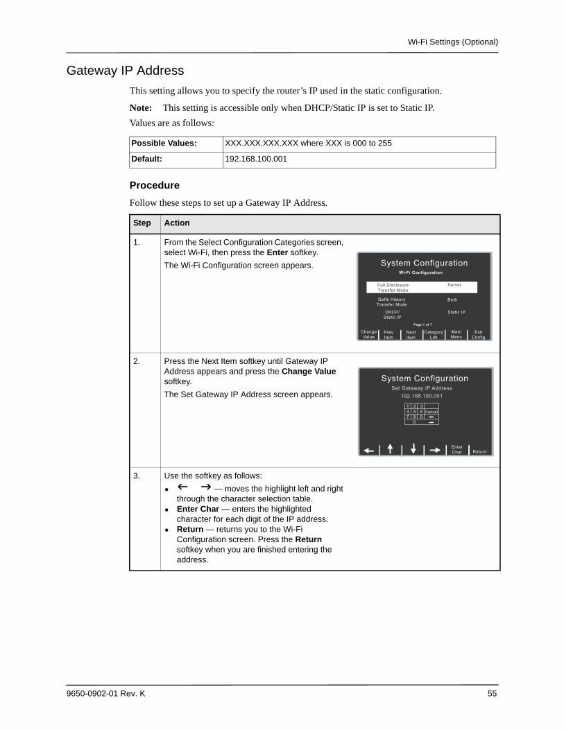
Wi-Fi Settings (Optional)
9650-0902-01 Rev. K 55
Gateway IP Address
This setting allows you to specify the router’s IP used in the static configuration.
Note: This setting is accessible only when DHCP/Static IP is set to Static IP.
Values are as follows:
Procedure
Follow these steps to set up a Gateway IP Address.
Possible Values: XXX.XXX.XXX.XXX where XXX is 000 to 255
Default: 192.168.100.001
Step Action
1. From the Select Configuration Categories screen, select Wi-Fi, then press the Enter softkey.
The Wi-Fi Configuration screen appears.
2. Press the Next Item softkey until Gateway IP Address appears and press the Change Value softkey.
The Set Gateway IP Address screen appears.
3. Use the softkey as follows:
• — moves the highlight left and right through the character selection table.
• Enter Char — enters the highlighted character for each digit of the IP address.
• Return — returns you to the Wi-Fi Configuration screen. Press the Return softkey when you are finished entering the address.
NextItem
PrevItem
System Configuration
Wi-Fi Configuration
Defib History
Transfer Mode
DHCP/Static IP
Both
Static IP
MainMenu
ExitConfig
CategoryList
ChangeValue
Full DisclosureTransfer Mode
Server
Page 1 of 7
System Configuration
Set Gateway IP Address192.168.100.001
.
ReturnEnterChar
1Cancel4
7
258
369
0 <
<
.
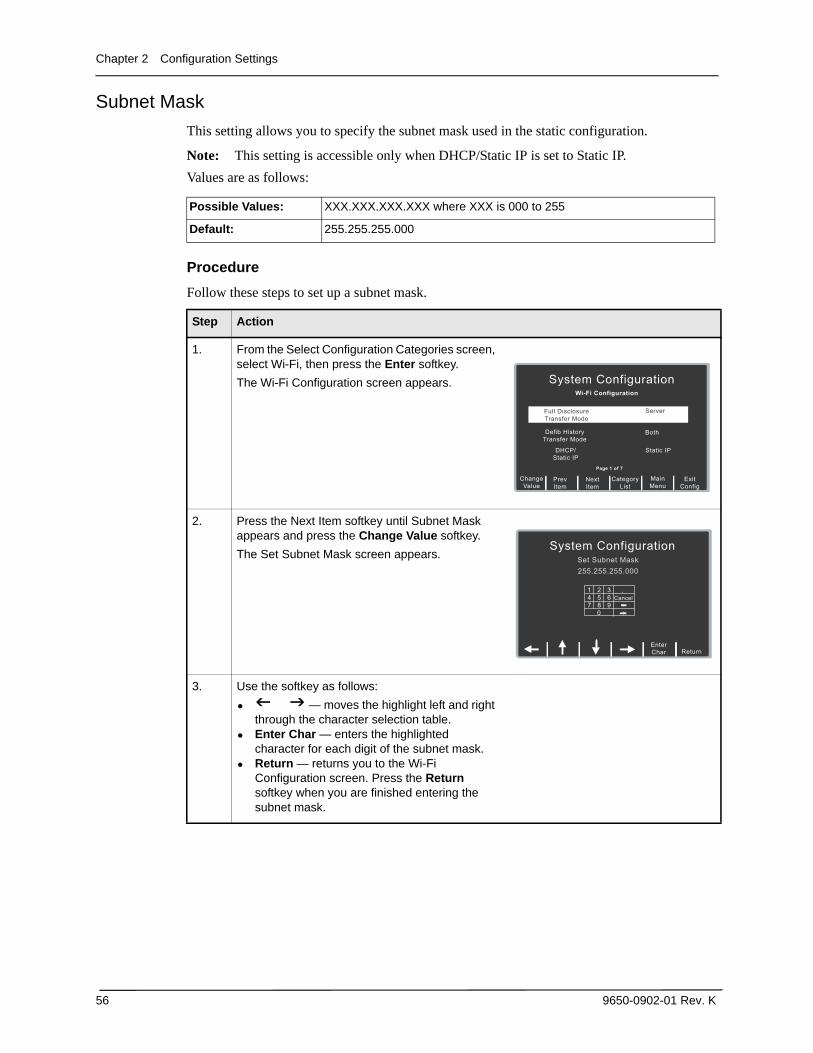
Chapter 2 Configuration Settings
56 9650-0902-01 Rev. K
Subnet Mask
This setting allows you to specify the subnet mask used in the static configuration.
Note: This setting is accessible only when DHCP/Static IP is set to Static IP.
Values are as follows:
Procedure
Follow these steps to set up a subnet mask.
Possible Values: XXX.XXX.XXX.XXX where XXX is 000 to 255
Default: 255.255.255.000
Step Action
1. From the Select Configuration Categories screen, select Wi-Fi, then press the Enter softkey.
The Wi-Fi Configuration screen appears.
2. Press the Next Item softkey until Subnet Mask appears and press the Change Value softkey.
The Set Subnet Mask screen appears.
3. Use the softkey as follows:
• — moves the highlight left and right through the character selection table.
• Enter Char — enters the highlighted character for each digit of the subnet mask.
• Return — returns you to the Wi-Fi Configuration screen. Press the Return softkey when you are finished entering the subnet mask.
NextItem
PrevItem
System Configuration
Wi-Fi Configuration
Defib History
Transfer Mode
DHCP/Static IP
Both
Static IP
MainMenu
ExitConfig
CategoryList
ChangeValue
Full DisclosureTransfer Mode
Server
Page 1 of 7
System Configuration
Set Subnet Mask255.255.255.000
ReturnEnterChar
1Cancel4
7
258
369
0 <
<
.
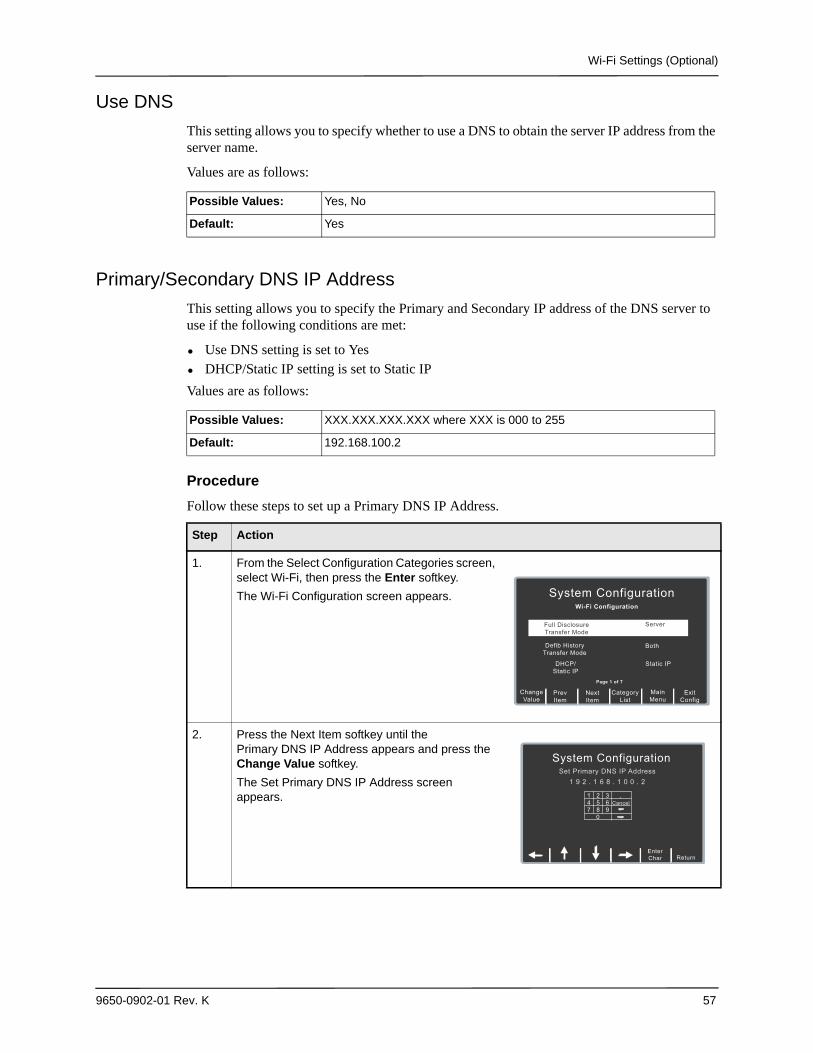
Wi-Fi Settings (Optional)
9650-0902-01 Rev. K 57
Use DNS
This setting allows you to specify whether to use a DNS to obtain the server IP address from the server name.
Values are as follows:
Primary/Secondary DNS IP Address
This setting allows you to specify the Primary and Secondary IP address of the DNS server to use if the following conditions are met:
• Use DNS setting is set to Yes• DHCP/Static IP setting is set to Static IP
Values are as follows:
Procedure
Follow these steps to set up a Primary DNS IP Address.
Possible Values: Yes, No
Default: Yes
Possible Values: XXX.XXX.XXX.XXX where XXX is 000 to 255
Default: 192.168.100.2
Step Action
1. From the Select Configuration Categories screen, select Wi-Fi, then press the Enter softkey.
The Wi-Fi Configuration screen appears.
2. Press the Next Item softkey until the Primary DNS IP Address appears and press the Change Value softkey.
The Set Primary DNS IP Address screen appears.
NextItem
PrevItem
System Configuration
Wi-Fi Configuration
Defib History
Transfer Mode
DHCP/Static IP
Both
Static IP
MainMenu
ExitConfig
CategoryList
ChangeValue
Full DisclosureTransfer Mode
Server
Page 1 of 7
System ConfigurationSet Primary DNS IP Address
1 9 2 . 1 6 8 . 1 0 0 . 2
ReturnEnterChar
1Cancel4
7
258
369
0 <
<
.
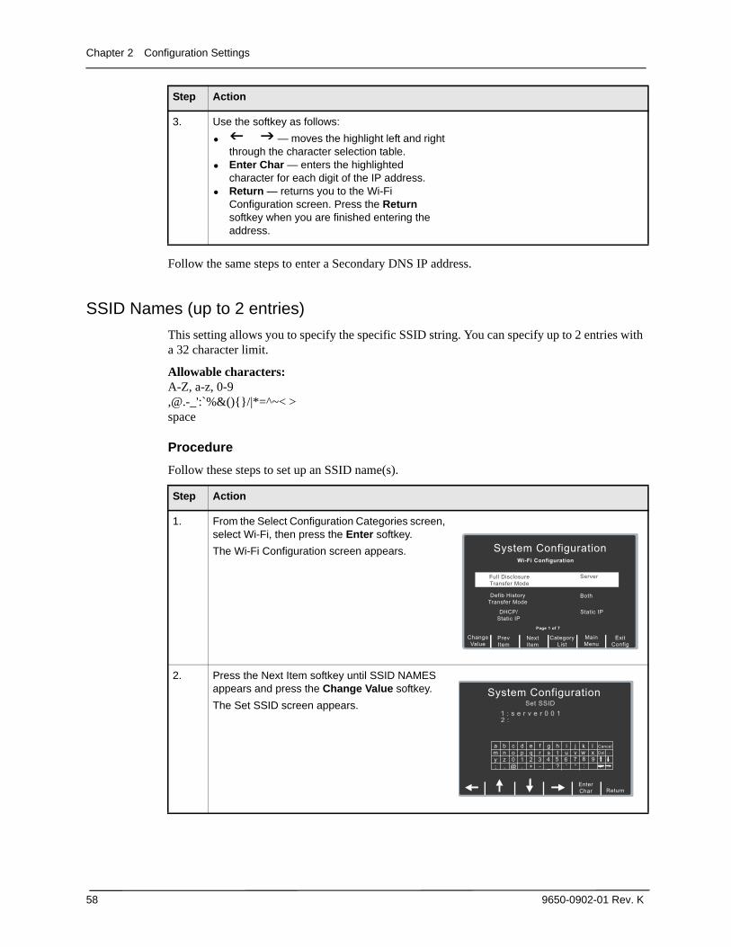
Chapter 2 Configuration Settings
58 9650-0902-01 Rev. K
Follow the same steps to enter a Secondary DNS IP address.
SSID Names (up to 2 entries)
This setting allows you to specify the specific SSID string. You can specify up to 2 entries with a 32 character limit.
Allowable characters: A-Z, a-z, 0-9,@.-_':`%&(){}/|*=^~< >space
Procedure
Follow these steps to set up an SSID name(s).
3. Use the softkey as follows:
• — moves the highlight left and right through the character selection table.
• Enter Char — enters the highlighted character for each digit of the IP address.
• Return — returns you to the Wi-Fi Configuration screen. Press the Return softkey when you are finished entering the address.
Step Action
Step Action
1. From the Select Configuration Categories screen, select Wi-Fi, then press the Enter softkey.
The Wi-Fi Configuration screen appears.
2. Press the Next Item softkey until SSID NAMES appears and press the Change Value softkey.
The Set SSID screen appears.
NextItem
PrevItem
System Configuration
Wi-Fi Configuration
Defib History
Transfer Mode
DHCP/Static IP
Both
Static IP
MainMenu
ExitConfig
CategoryList
ChangeValue
Full DisclosureTransfer Mode
Server
Page 1 of 7
System Configuration
Set SSID1 : s e r v e r 0 0 12 :
a
;
my
b
,
nz
c
@
o0
d
.
p1
e
+
q2
f
-
r3
g
_
s4
h
?
t6
i
‘
uj
“
vCancel
ReturnEnterChar
<
wk l
x
<8 95:
7Del ...
<
<
<
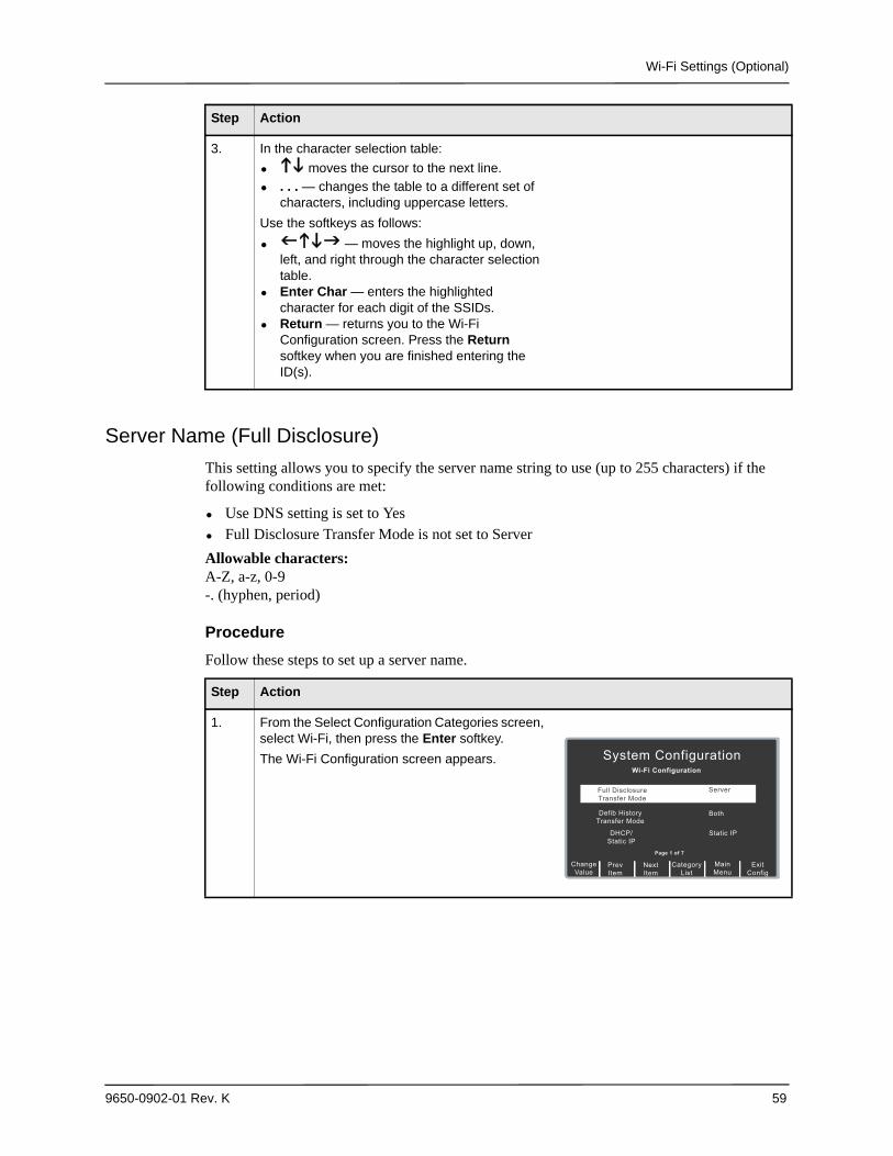
Wi-Fi Settings (Optional)
9650-0902-01 Rev. K 59
Server Name (Full Disclosure)
This setting allows you to specify the server name string to use (up to 255 characters) if the following conditions are met:
• Use DNS setting is set to Yes• Full Disclosure Transfer Mode is not set to Server
Allowable characters:A-Z, a-z, 0-9-. (hyphen, period)
Procedure
Follow these steps to set up a server name.
3. In the character selection table:
• moves the cursor to the next line.
• . . . — changes the table to a different set of characters, including uppercase letters.
Use the softkeys as follows:
• — moves the highlight up, down, left, and right through the character selection table.
• Enter Char — enters the highlighted character for each digit of the SSIDs.
• Return — returns you to the Wi-Fi Configuration screen. Press the Return softkey when you are finished entering the ID(s).
Step Action
Step Action
1. From the Select Configuration Categories screen, select Wi-Fi, then press the Enter softkey.
The Wi-Fi Configuration screen appears.
NextItem
PrevItem
System Configuration
Wi-Fi Configuration
Defib History
Transfer Mode
DHCP/Static IP
Both
Static IP
MainMenu
ExitConfig
CategoryList
ChangeValue
Full DisclosureTransfer Mode
Server
Page 1 of 7
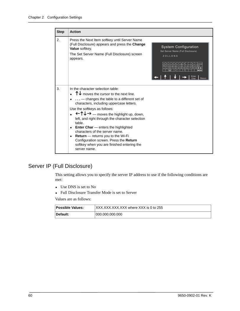
Chapter 2 Configuration Settings
60 9650-0902-01 Rev. K
Server IP (Full Disclosure)
This setting allows you to specify the server IP address to use if the following conditions are met:
• Use DNS is set to No• Full Disclosure Transfer Mode is set to Server
Values are as follows:
2. Press the Next Item softkey until Server Name (Full Disclosure) appears and press the Change Value softkey.
The Set Server Name (Full Disclosure) screen appears.
3. In the character selection table:
• moves the cursor to the next line.
• . . . — changes the table to a different set of characters, including uppercase letters.
Use the softkeys as follows:
• — moves the highlight up, down, left, and right through the character selection table.
• Enter Char — enters the highlighted characters of the server name.
• Return — returns you to the Wi-Fi Configuration screen. Press the Return softkey when you are finished entering the server name.
Step Action
System Configuration
Set Server Name (Full Disclosure)
Z O L L D N S
a
;
my
b
,
nz
c
@
o0
d
.
p1
e
+
q2
f
-
r3
g
_
s4
h
?
t6
i
‘
uj
“
vCancel
ReturnEnterChar
<
wk l
x
<8 95:
7Del ...
<
<
<
Possible Values: XXX.XXX.XXX.XXX where XXX is 0 to 255
Default: 000.000.000.000
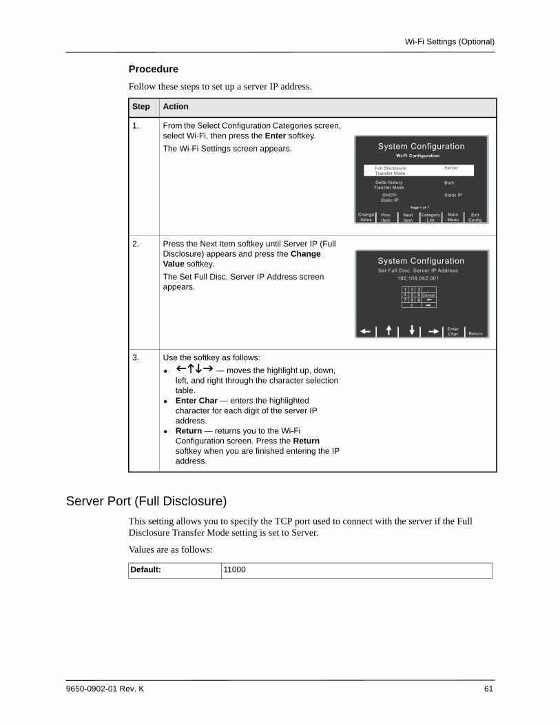
Wi-Fi Settings (Optional)
9650-0902-01 Rev. K 61
Procedure
Follow these steps to set up a server IP address.
Server Port (Full Disclosure)
This setting allows you to specify the TCP port used to connect with the server if the Full Disclosure Transfer Mode setting is set to Server.
Values are as follows:
Step Action
1. From the Select Configuration Categories screen, select Wi-Fi, then press the Enter softkey.
The Wi-Fi Settings screen appears.
2. Press the Next Item softkey until Server IP (Full Disclosure) appears and press the Change Value softkey.
The Set Full Disc. Server IP Address screen appears.
3. Use the softkey as follows:
• — moves the highlight up, down, left, and right through the character selection table.
• Enter Char — enters the highlighted character for each digit of the server IP address.
• Return — returns you to the Wi-Fi Configuration screen. Press the Return softkey when you are finished entering the IP address.
NextItem
PrevItem
System Configuration
Wi-Fi Configuration
Defib History
Transfer Mode
DHCP/Static IP
Both
Static IP
MainMenu
ExitConfig
CategoryList
ChangeValue
Full DisclosureTransfer Mode
Server
Page 1 of 7
System Configuration
Set Full Disc. Server IP Address192.168.042.001
ReturnEnterChar
1Cancel4
7
258
369
0 <
<
.
Default: 11000
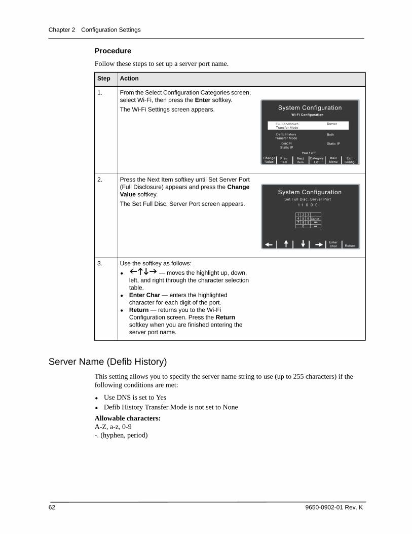
Chapter 2 Configuration Settings
62 9650-0902-01 Rev. K
Procedure
Follow these steps to set up a server port name.
Server Name (Defib History)
This setting allows you to specify the server name string to use (up to 255 characters) if the following conditions are met:
• Use DNS is set to Yes• Defib History Transfer Mode is not set to None
Allowable characters:A-Z, a-z, 0-9-. (hyphen, period)
Step Action
1. From the Select Configuration Categories screen, select Wi-Fi, then press the Enter softkey.
The Wi-Fi Settings screen appears.
2. Press the Next Item softkey until Set Server Port (Full Disclosure) appears and press the Change Value softkey.
The Set Full Disc. Server Port screen appears.
3. Use the softkey as follows:
• — moves the highlight up, down, left, and right through the character selection table.
• Enter Char — enters the highlighted character for each digit of the port.
• Return — returns you to the Wi-Fi Configuration screen. Press the Return softkey when you are finished entering the server port name.
NextItem
PrevItem
System Configuration
Wi-Fi Configuration
Defib History
Transfer Mode
DHCP/Static IP
Both
Static IP
MainMenu
ExitConfig
CategoryList
ChangeValue
Full DisclosureTransfer Mode
Server
Page 1 of 7
System Configuration
Set Full Disc. Server Port1 1 0 0 0
ReturnEnterChar
1Cancel4
7
258
369
0 <
<
.
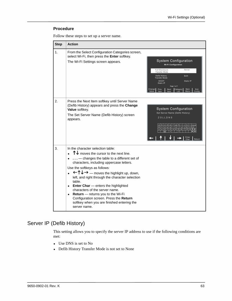
Wi-Fi Settings (Optional)
9650-0902-01 Rev. K 63
Procedure
Follow these steps to set up a server name.
Server IP (Defib History)
This setting allows you to specify the server IP address to use if the following conditions are met:
• Use DNS is set to No• Defib History Transfer Mode is not set to None
Step Action
1. From the Select Configuration Categories screen, select Wi-Fi, then press the Enter softkey.
The Wi-Fi Settings screen appears.
2. Press the Next Item softkey until Server Name (Defib History) appears and press the Change Value softkey.
The Set Server Name (Defib History) screen appears.
3. In the character selection table:
• moves the cursor to the next line.
• . . . — changes the table to a different set of characters, including uppercase letters.
Use the softkeys as follows:
• — moves the highlight up, down, left, and right through the character selection table.
• Enter Char — enters the highlighted characters of the server name.
• Return — returns you to the Wi-Fi Configuration screen. Press the Return softkey when you are finished entering the server name.
NextItem
PrevItem
System Configuration
Wi-Fi Configuration
Defib History
Transfer Mode
DHCP/Static IP
Both
Static IP
MainMenu
ExitConfig
CategoryList
ChangeValue
Full DisclosureTransfer Mode
Server
Page 1 of 7
System Configuration
Set Server Name (Defib History)
Z O L L D N S
a
;
my
b
,
nz
c
@
o0
d
.
p1
e
+
q2
f
-
r3
g
_
s4
h
?
t6
i
‘
uj
“
vCancel
ReturnEnterChar
<
wk l
x
<8 95:
7Del ...
<
<
<
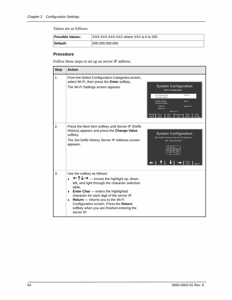
Chapter 2 Configuration Settings
64 9650-0902-01 Rev. K
Values are as follows:
Procedure
Follow these steps to set up an server IP address.
Possible Values: XXX.XXX.XXX.XXX where XXX is 0 to 255
Default: 000.000.000.000
Step Action
1. From the Select Configuration Categories screen, select Wi-Fi, then press the Enter softkey.
The Wi-Fi Settings screen appears.
2. Press the Next Item softkey until Server IP (Defib History) appears and press the Change Value softkey.
The Set Defib History Server IP Address screen appears.
3. Use the softkey as follows:
• — moves the highlight up, down, left, and right through the character selection table.
• Enter Char — enters the highlighted character for each digit of the server IP.
• Return — returns you to the Wi-Fi Configuration screen. Press the Return softkey when you are finished entering the server IP.
NextItem
PrevItem
System Configuration
Wi-Fi Configuration
Defib History
Transfer Mode
DHCP/Static IP
Both
Static IP
MainMenu
ExitConfig
CategoryList
ChangeValue
Full DisclosureTransfer Mode
Server
Page 1 of 7
System Configuration
Set Defib History Server IP Address192.168.042.001
ReturnEnterChar
1Cancel4
7
258
369
0 <
<
.
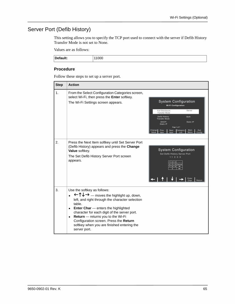
Wi-Fi Settings (Optional)
9650-0902-01 Rev. K 65
Server Port (Defib History)
This setting allows you to specify the TCP port used to connect with the server if Defib History Transfer Mode is not set to None.
Values are as follows:
Procedure
Follow these steps to set up a server port.
Default: 11000
Step Action
1. From the Select Configuration Categories screen, select Wi-Fi, then press the Enter softkey.
The Wi-Fi Settings screen appears.
2. Press the Next Item softkey until Set Server Port (Defib History) appears and press the Change Value softkey.
The Set Defib History Server Port screen appears.
3. Use the softkey as follows:
• — moves the highlight up, down, left, and right through the character selection table.
• Enter Char — enters the highlighted character for each digit of the server port.
• Return — returns you to the Wi-Fi Configuration screen. Press the Return softkey when you are finished entering the server port.
NextItem
PrevItem
System Configuration
Wi-Fi Configuration
Defib History
Transfer Mode
DHCP/Static IP
Both
Static IP
MainMenu
ExitConfig
CategoryList
ChangeValue
Full DisclosureTransfer Mode
Server
Page 1 of 7
System Configuration
Set Defib History Server Port1 1 0 0 0
ReturnEnterChar
1Cancel4
7
258
369
0 <
<
.
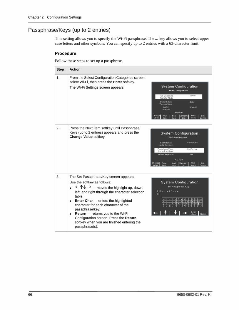
Chapter 2 Configuration Settings
66 9650-0902-01 Rev. K
Passphrase/Keys (up to 2 entries)
This setting allows you to specify the Wi-Fi passphrase. The ... key allows you to select upper case letters and other symbols. You can specify up to 2 entries with a 63-character limit.
Procedure
Follow these steps to set up a passphrase.
Step Action
1. From the Select Configuration Categories screen, select Wi-Fi, then press the Enter softkey.
The Wi-Fi Settings screen appears.
2. Press the Next Item softkey until Passphrase/Keys (up to 2 entries) appears and press the Change Value softkey.
3. The Set Passphrase/Key screen appears.
Use the softkey as follows:
• — moves the highlight up, down, left, and right through the character selection table.
• Enter Char — enters the highlighted character for each character of the passphrase/key.
• Return — returns you to the Wi-Fi Configuration screen. Press the Return softkey when you are finished entering the passphrase(s).
NextItem
PrevItem
System Configuration
Wi-Fi Configuration
Defib History
Transfer Mode
DHCP/Static IP
Both
Static IP
MainMenu
ExitConfig
CategoryList
ChangeValue
Full DisclosureTransfer Mode
Server
Page 1 of 7
NextItem
PrevItem
System Configuration
Wi-Fi Configuration
Enable Report ID Yes
MainMenu
ExitConfig
CategoryList
ChangeValue
SSID Names(up to 2 entries)
Set/Review
Page 6 of 7
Passphrase/Keys(up to 2 entries)
Set/Review
System Configuration
Set Passphrase/Key
1: S e c r e t C o d e2:
a
;
my
b
,
nz
c
@
o0
d
.
p1
e
+
q2
f
-
r3
g
_
s4
h
?
t6
i
‘
uj
“
vCancel
ReturnEnterChar
<
wk l
x
<8 95:
7Del ...
<
<
<
Wi-Fi Transmission Mode Options
9650-0902-01 Rev. K 67
Wi-Fi Transmission Mode Options
Enable Report ID
This setting allows you to enable or disable the option to enter a unique alphanumeric patient ID before Wi-Fi transmission of a Full Disclosure report. If set to No, the report will be sent automatically.
Values are as follows:
Wi-Fi Region
This setting allows you to specify the Wi-Fi domain (United States, Japan, or Europe).
Values are as follows:
Wi-Fi Radio
This setting allows you to specify the Wi-Fi radio 802.11 standard.
Values are as follows:
Possible Values: Yes, No
Default: No
Possible Values: US, EU, JP
Default: US
Possible Values: b/g/n (2.4GHz), a/n (5GHz)
Default: b/g/n (2.4GHz)

Chapter 2 Configuration Settings
68 9650-0902-01 Rev. K