Embed Size (px)
Citation preview
R525P Single Axis Driver, Closed-Loop Driver, Simple Speed Controller
User Manual And Commands Guide Version 1.00
RMS Technologies 2533 N. Carson St. #4698, Carson City, NV 89706-0147
Thank you for purchasing the R525P Single-Axis Step & Direction Driver. This driver also operates as a closed-loop driver or a simple speed controller/driver. This product is warranted to be free of manufacturing defects for one (1) year from the date of purchase. PLEASE READ BEFORE USING Before you start, you must have a suitable step motor and a DC power supply suitable for the motor. The power supply voltage must be between 4 times and 20 times the motor's rated voltage. DISCLAIMER The information provided in this document is believed to be reliable. However, no responsibility is assumed for any possible inaccuracies or omissions. Specifications are subject to change without notice. RMS Technologies reserves the right to make changes without further notice to any products herein to improve reliability, function, or design. RMS Technologies does not assume any liability arising out of the application or use of any product or circuit described herein; neither does it convey any license under its patent rights, nor the rights of others.
Special Symbols Indicates a WARNING and that this information could prevent injury, loss of property, or even death (in extreme cases).
R525P User Manual & Commands Page 2 of 49 12/8/2014 Version 1.0
R525P User Manual Product: R525P Version: 1.00 Date: 12/8/2014
Version History
Version Date Description of Changes
1.00 12/8/2014 New User Manual
R525P User Manual & Commands Page 3 of 49 12/8/2014 Version 1.0
Table of Contents
Contents 1. FEATURES ................................................................................................................................................................... 5 2. ELECTRICAL SPECIFICATIONS ..................................................................................................................................... 5 3. OPERATING SPECIFICATIONS ..................................................................................................................................... 6 4. MECHANICAL SPECIFICATIONS .................................................................................................................................. 6 5. PIN ASSIGNMENTS ..................................................................................................................................................... 7 6. CONNECTION SPECIFICATIONS ................................................................................................................................ 10
Basic Setup ............................................................................................................................................................... 10 RS485 Connection .................................................................................................................................................... 12 Default Settings ....................................................................................................................................................... 12
7. GUI INTERFRACE ...................................................................................................................................................... 13 Changing Modes in the GUI ..................................................................................................................................... 14 Status LED ................................................................................................................................................................ 14
8. DRIVER SETTINGS ..................................................................................................................................................... 15 9. CURRENT LOOP TUNING PROCEDURE ..................................................................................................................... 16
Capture .................................................................................................................................................................... 17 Ki .............................................................................................................................................................................. 17 Examples of Step Responses.................................................................................................................................... 18
10. ENCODER SETTINGS ............................................................................................................................................... 19 11. STALL DETECTION .................................................................................................................................................. 20 12. OUTPUT SETTINGS ................................................................................................................................................. 20 13. Using Analog Input - ADC Settings ......................................................................................................................... 21 14. Open Loop Velocity Mode SETTINGS ..................................................................................................................... 22 15. Open Loop Position Mode SETTINGS ..................................................................................................................... 23 16. Closed Loop Torque Mode SETTINGS .................................................................................................................... 24 17. Closed Loop Velocity Mode SETTINGS ................................................................................................................... 25
Setting Kp and Ki for Closed Loop Velocity .............................................................................................................. 25 18. Closed Loop Position Mode SETTINGS ................................................................................................................... 26
Setting Kp and Ki for Closed Loop Position .............................................................................................................. 26 19. COMMANDS SET – CONTROLLER MODE ............................................................................................................... 27
Syntax of Commands ............................................................................................................................................... 27 Status LED ................................................................................................................................................................ 47
APPENDIX A: Graphing Capabilities with GUI .............................................................................................................. 48 APPENDIX B: Example Programming ........................................................................................................................... 49
R525P User Manual & Commands Page 4 of 49 12/8/2014 Version 1.0
1. FEATURES
• Single axis driver for bipolar step motors • GUI interface that enables users to choose the following operational modes:
o Open Loop Velocity Mode o Open Loop Position Mode o Closed Loop Torque Mode o Closed Loop Velocity Mode o Closed Loop Position Mode o Analog input Mode
• Operates from +12 to 48VDC • Software selectable run currents from 0.1 to 5.0 Amps Peak (in 0.05 A increments) • Software selectable hold currents from 0 to 5.0 Amps Peak (in 0.05 A increments) • Software selectable step resolutions from Full step, 2x, 4x, 5x, 8x, 10x, 16x, 25x, 32x, 50x, 64x,
125x, 128x, 250x, 256x microstepping • Communication via RS485 and USB automatically available on the R525P driver itself (no
converter card required) • Operates in both open loop and closed loop modes • Programmable analog input to change velocity and position control • Programmable digital output for feedback • WhisperDrive Technology for super smooth and quiet operation
2. ELECTRICAL SPECIFICATIONS Supply Voltage: +12 to 48 VDC Phase Current: 0.1 to 5.0 Amps Peak
NOTE: Phase current of 2.7 Amp and above REQUIRES an additional heatsink, make sure the temperature of the bracket does not exceed 45° C.
I/O Specifications 3x Optically Isolated Inputs (1 fixed) Step Direction Disable/Enable 1x Analog input 1x Digital Output which can output one of the following (via GUI interface): Output disabled (open) – not used Motor direction detection (Open = CW, Closed = CCW) Closed on Hardware Fault Toggle when Index on Encoder is detected Close when motor is stalled Close when motor is moving Close when motor is holding
R525P User Manual & Commands Page 5 of 49 12/8/2014 Version 1.0
3. OPERATING SPECIFICATIONS Maximum Step Frequency: 1 MHz Operating Temperature: Low end – 0° C
High end – Dependent on case temperature, bracket temperature must not exceed 45° C
Automatic Motor Holding Current reduction available from 0 to 5 Amps Logic Timing
Minimum Step Pulse Width 200 nanoseconds Maximum Power-Down Recovery Time 500 milliseconds
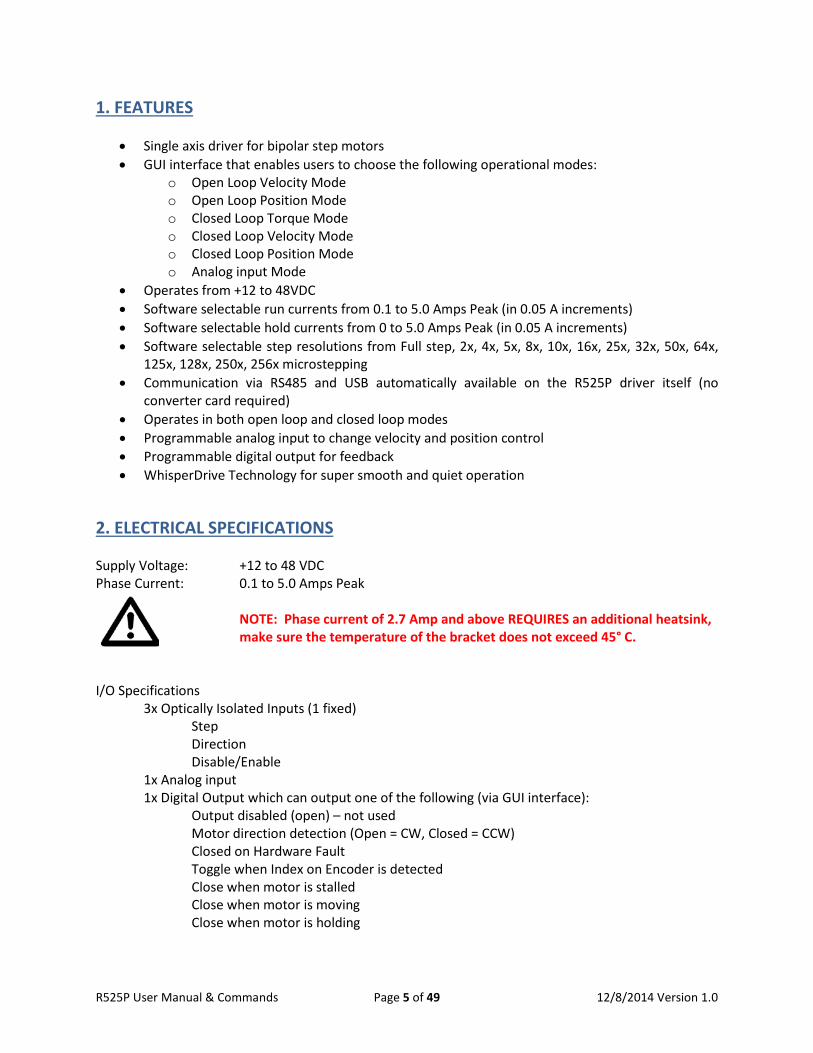
4. MECHANICAL SPECIFICATIONS Approximate Size: 2.21” x 2.21” x 1.27” height Weight: 4.6 oz Mounting: Four Through-hole locations, 1.860”x1.860”. Maximum slot size 0.15” (4X) Housing and Base Plate: Aluminum, Hard Anodized
Image 4.0 – Mechanical Dimensions
R525P User Manual & Commands Page 6 of 49 12/8/2014 Version 1.0
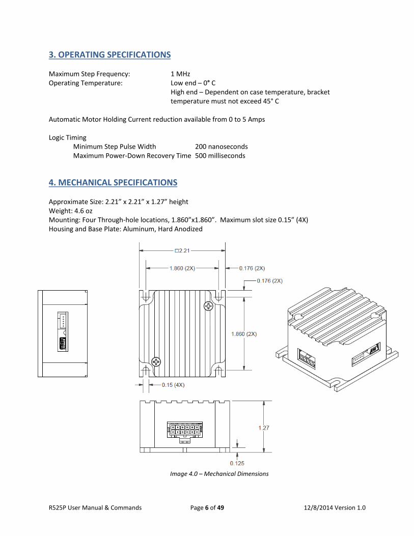
5. PIN ASSIGNMENTS
Image 5.0 – Overall Connector Location and Label
P1 Motor Connector Pin-Outs Pin Function Color 1 Motor Phase A Red 2 Motor Phase A Blue 3 Motor Phase B Green 4 Motor Phase B Black
Table 5.0 – P1 Pin-out Table
Image 5.1 – P1 Pin-Out Location
P2 Encoder Connector Pin-Outs Pin Function Color 1 Channel B Blue 2 5V input Red 3 Channel A Yellow 4 Index White 5 Ground Green Table 5.1 – P2 Encoder Pin-out Table
Image 5.2 – P2 Pin-Out Location
Motor Connector P1 Encoder Connector
P2
Mini USB Connector P3
12-Pin I/O Connector P4
1 2 3 4 5
P2
P1
R525P User Manual & Commands Page 7 of 49 12/8/2014 Version 1.0
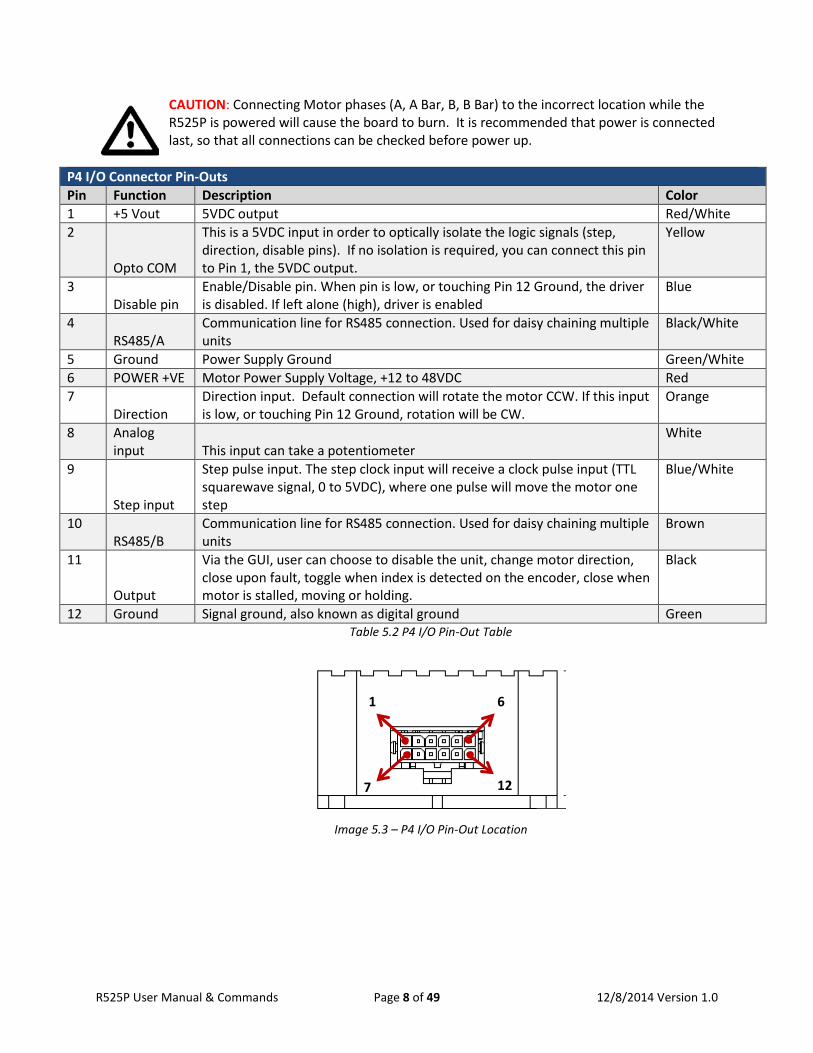
CAUTION: Connecting Motor phases (A, A Bar, B, B Bar) to the incorrect location while the R525P is powered will cause the board to burn. It is recommended that power is connected last, so that all connections can be checked before power up.
P4 I/O Connector Pin-Outs Pin Function Description Color 1 +5 Vout 5VDC output Red/White 2
Opto COM
This is a 5VDC input in order to optically isolate the logic signals (step, direction, disable pins). If no isolation is required, you can connect this pin to Pin 1, the 5VDC output.
Yellow
3 Disable pin
Enable/Disable pin. When pin is low, or touching Pin 12 Ground, the driver is disabled. If left alone (high), driver is enabled
Blue
4 RS485/A
Communication line for RS485 connection. Used for daisy chaining multiple units
Black/White
5 Ground Power Supply Ground Green/White 6 POWER +VE Motor Power Supply Voltage, +12 to 48VDC Red 7
Direction Direction input. Default connection will rotate the motor CCW. If this input is low, or touching Pin 12 Ground, rotation will be CW.
Orange
8 Analog input This input can take a potentiometer
White
9
Step input
Step pulse input. The step clock input will receive a clock pulse input (TTL squarewave signal, 0 to 5VDC), where one pulse will move the motor one step
Blue/White
10 RS485/B
Communication line for RS485 connection. Used for daisy chaining multiple units
Brown
11
Output
Via the GUI, user can choose to disable the unit, change motor direction, close upon fault, toggle when index is detected on the encoder, close when motor is stalled, moving or holding.
Black
12 Ground Signal ground, also known as digital ground Green Table 5.2 P4 I/O Pin-Out Table
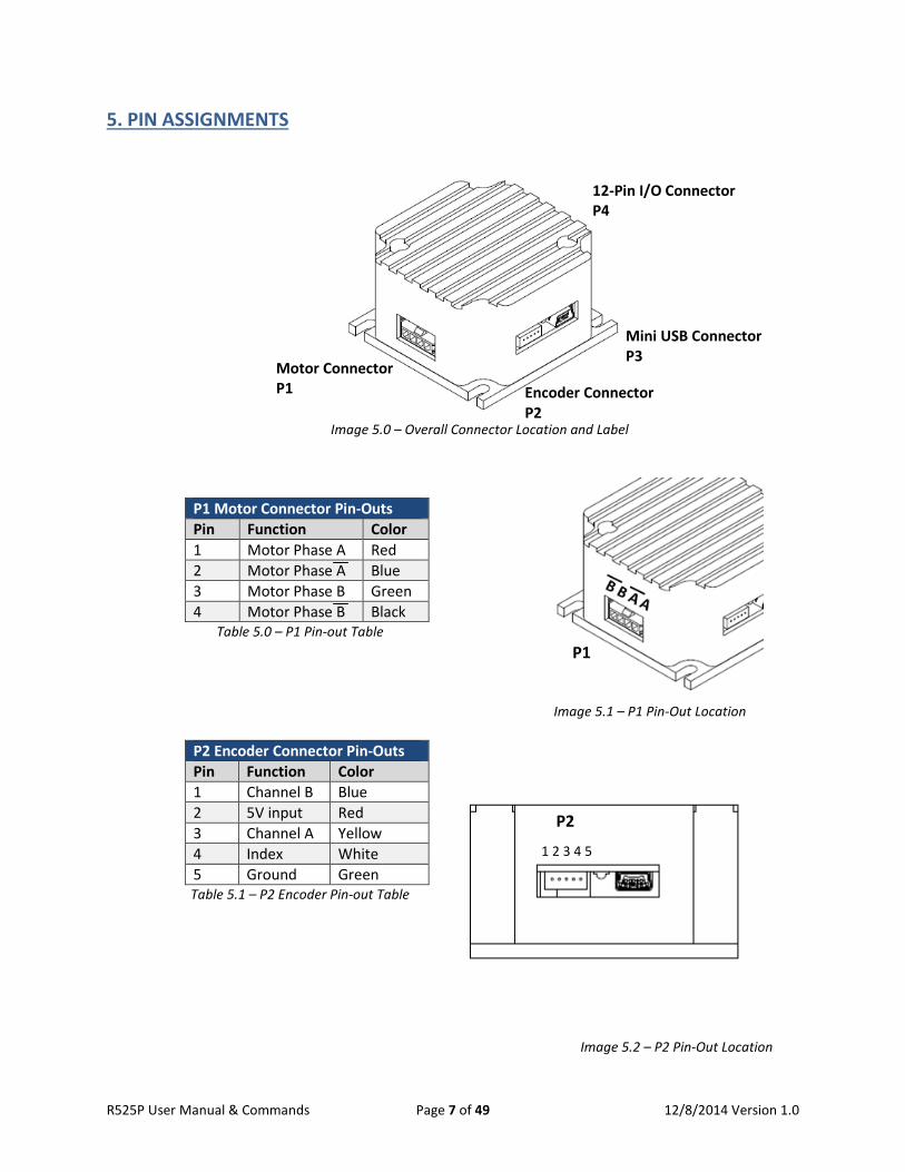
Image 5.3 – P4 I/O Pin-Out Location
1 6
7 12
R525P User Manual & Commands Page 8 of 49 12/8/2014 Version 1.0
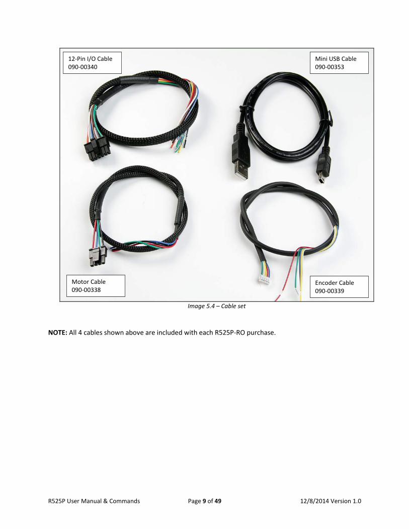
Image 5.4 – Cable set
NOTE: All 4 cables shown above are included with each R525P-RO purchase.
12-Pin I/O Cable 090-00340
Mini USB Cable 090-00353
Motor Cable 090-00338
Encoder Cable 090-00339
R525P User Manual & Commands Page 9 of 49 12/8/2014 Version 1.0
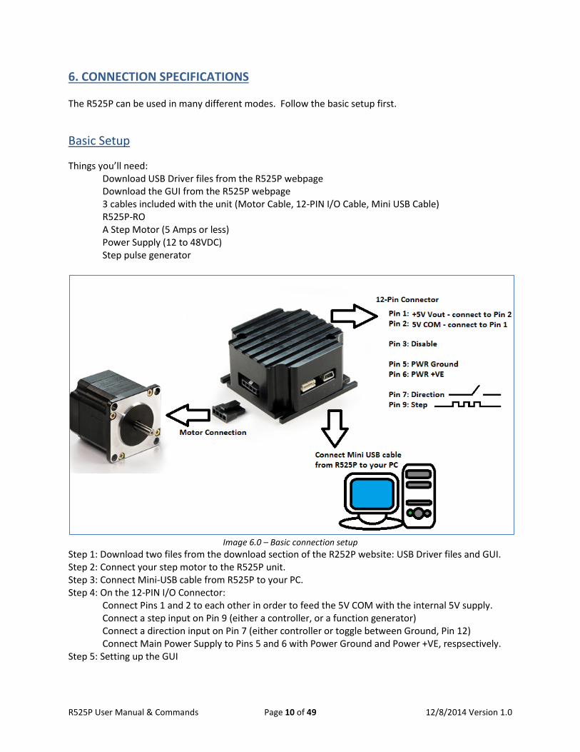
6. CONNECTION SPECIFICATIONS The R525P can be used in many different modes. Follow the basic setup first.
Basic Setup Things you’ll need: Download USB Driver files from the R525P webpage
Download the GUI from the R525P webpage 3 cables included with the unit (Motor Cable, 12-PIN I/O Cable, Mini USB Cable) R525P-RO A Step Motor (5 Amps or less) Power Supply (12 to 48VDC) Step pulse generator
Image 6.0 – Basic connection setup
Step 1: Download two files from the download section of the R252P website: USB Driver files and GUI. Step 2: Connect your step motor to the R525P unit. Step 3: Connect Mini-USB cable from R525P to your PC. Step 4: On the 12-PIN I/O Connector: Connect Pins 1 and 2 to each other in order to feed the 5V COM with the internal 5V supply. Connect a step input on Pin 9 (either a controller, or a function generator) Connect a direction input on Pin 7 (either controller or toggle between Ground, Pin 12) Connect Main Power Supply to Pins 5 and 6 with Power Ground and Power +VE, respsectively. Step 5: Setting up the GUI
R525P User Manual & Commands Page 10 of 49 12/8/2014 Version 1.0
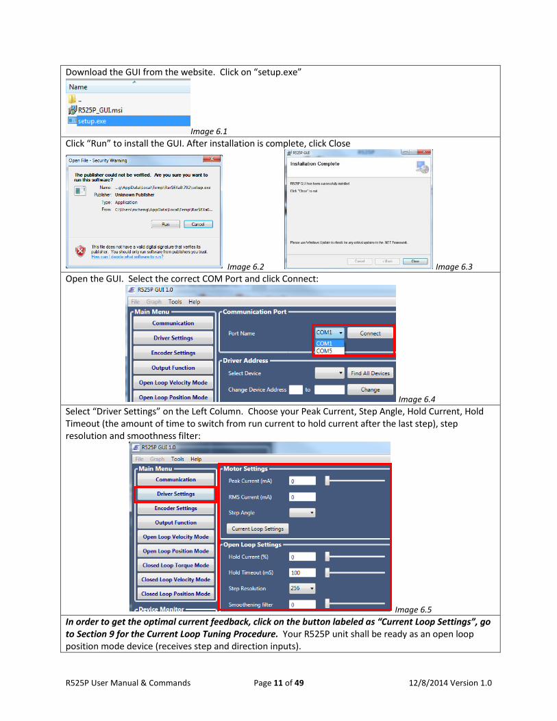
Download the GUI from the website. Click on “setup.exe”
Image 6.1 Click “Run” to install the GUI. After installation is complete, click Close
Image 6.2 Image 6.3 Open the GUI. Select the correct COM Port and click Connect:
Image 6.4 Select “Driver Settings” on the Left Column. Choose your Peak Current, Step Angle, Hold Current, Hold Timeout (the amount of time to switch from run current to hold current after the last step), step resolution and smoothness filter:
Image 6.5 In order to get the optimal current feedback, click on the button labeled as “Current Loop Settings”, go to Section 9 for the Current Loop Tuning Procedure. Your R525P unit shall be ready as an open loop position mode device (receives step and direction inputs).
R525P User Manual & Commands Page 11 of 49 12/8/2014 Version 1.0
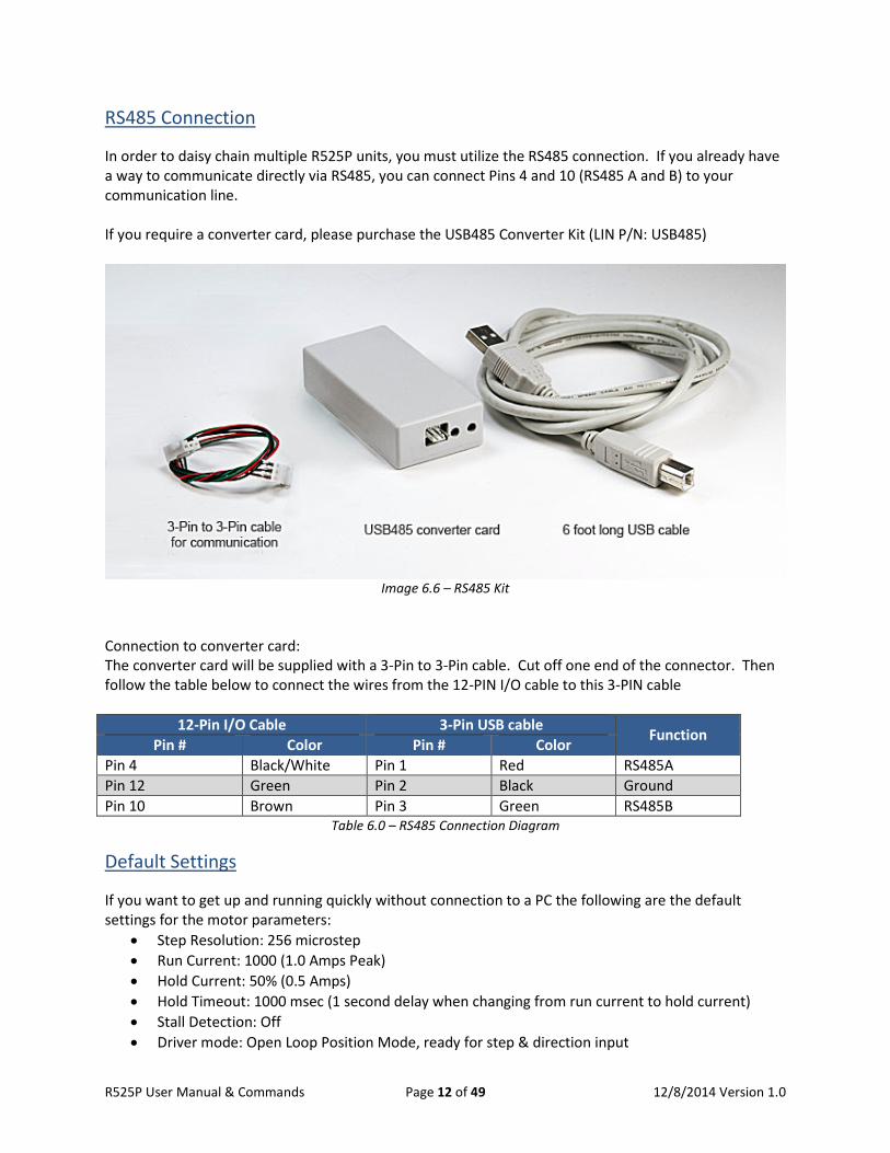
RS485 Connection In order to daisy chain multiple R525P units, you must utilize the RS485 connection. If you already have a way to communicate directly via RS485, you can connect Pins 4 and 10 (RS485 A and B) to your communication line. If you require a converter card, please purchase the USB485 Converter Kit (LIN P/N: USB485)
Image 6.6 – RS485 Kit
Connection to converter card: The converter card will be supplied with a 3-Pin to 3-Pin cable. Cut off one end of the connector. Then follow the table below to connect the wires from the 12-PIN I/O cable to this 3-PIN cable
12-Pin I/O Cable 3-Pin USB cable Function Pin # Color Pin # Color Pin 4 Black/White Pin 1 Red RS485A Pin 12 Green Pin 2 Black Ground Pin 10 Brown Pin 3 Green RS485B
Table 6.0 – RS485 Connection Diagram
Default Settings If you want to get up and running quickly without connection to a PC the following are the default settings for the motor parameters:
• Step Resolution: 256 microstep • Run Current: 1000 (1.0 Amps Peak) • Hold Current: 50% (0.5 Amps) • Hold Timeout: 1000 msec (1 second delay when changing from run current to hold current) • Stall Detection: Off • Driver mode: Open Loop Position Mode, ready for step & direction input
R525P User Manual & Commands Page 12 of 49 12/8/2014 Version 1.0
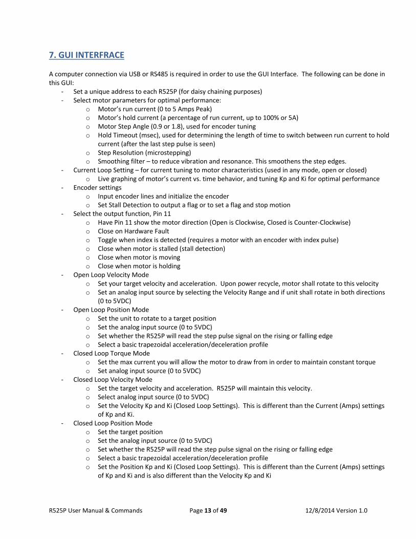
7. GUI INTERFRACE A computer connection via USB or RS485 is required in order to use the GUI Interface. The following can be done in this GUI:
- Set a unique address to each R525P (for daisy chaining purposes) - Select motor parameters for optimal performance:
o Motor’s run current (0 to 5 Amps Peak) o Motor’s hold current (a percentage of run current, up to 100% or 5A) o Motor Step Angle (0.9 or 1.8), used for encoder tuning o Hold Timeout (msec), used for determining the length of time to switch between run current to hold
current (after the last step pulse is seen) o Step Resolution (microstepping) o Smoothing filter – to reduce vibration and resonance. This smoothens the step edges.
- Current Loop Setting – for current tuning to motor characteristics (used in any mode, open or closed) o Live graphing of motor’s current vs. time behavior, and tuning Kp and Ki for optimal performance
- Encoder settings o Input encoder lines and initialize the encoder o Set Stall Detection to output a flag or to set a flag and stop motion
- Select the output function, Pin 11 o Have Pin 11 show the motor direction (Open is Clockwise, Closed is Counter-Clockwise) o Close on Hardware Fault o Toggle when index is detected (requires a motor with an encoder with index pulse) o Close when motor is stalled (stall detection) o Close when motor is moving o Close when motor is holding
- Open Loop Velocity Mode o Set your target velocity and acceleration. Upon power recycle, motor shall rotate to this velocity o Set an analog input source by selecting the Velocity Range and if unit shall rotate in both directions
(0 to 5VDC) - Open Loop Position Mode
o Set the unit to rotate to a target position o Set the analog input source (0 to 5VDC) o Set whether the R525P will read the step pulse signal on the rising or falling edge o Select a basic trapezoidal acceleration/deceleration profile
- Closed Loop Torque Mode o Set the max current you will allow the motor to draw from in order to maintain constant torque o Set analog input source (0 to 5VDC)
- Closed Loop Velocity Mode o Set the target velocity and acceleration. R525P will maintain this velocity. o Select analog input source (0 to 5VDC) o Set the Velocity Kp and Ki (Closed Loop Settings). This is different than the Current (Amps) settings
of Kp and Ki. - Closed Loop Position Mode
o Set the target position o Set the analog input source (0 to 5VDC) o Set whether the R525P will read the step pulse signal on the rising or falling edge o Select a basic trapezoidal acceleration/deceleration profile o Set the Position Kp and Ki (Closed Loop Settings). This is different than the Current (Amps) settings
of Kp and Ki and is also different than the Velocity Kp and Ki
R525P User Manual & Commands Page 13 of 49 12/8/2014 Version 1.0
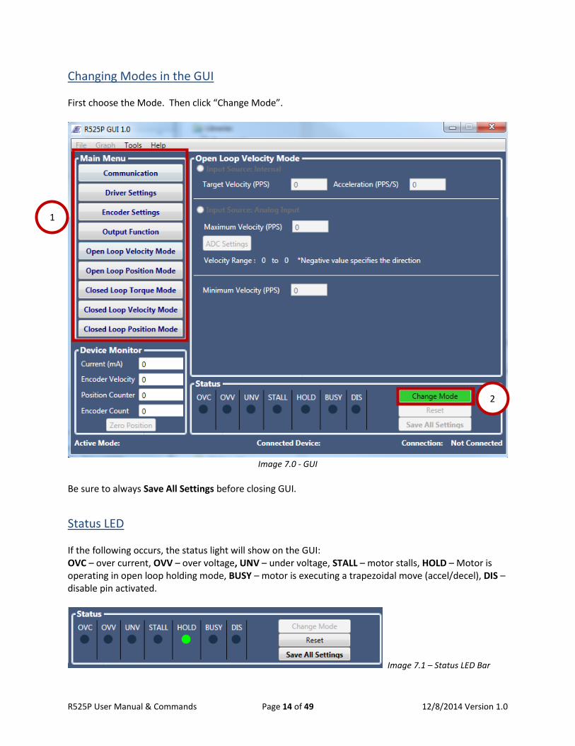
Changing Modes in the GUI First choose the Mode. Then click “Change Mode”.
Image 7.0 - GUI
Be sure to always Save All Settings before closing GUI.
Status LED If the following occurs, the status light will show on the GUI: OVC – over current, OVV – over voltage, UNV – under voltage, STALL – motor stalls, HOLD – Motor is operating in open loop holding mode, BUSY – motor is executing a trapezoidal move (accel/decel), DIS – disable pin activated.
Image 7.1 – Status LED Bar
1
2
R525P User Manual & Commands Page 14 of 49 12/8/2014 Version 1.0

8. DRIVER SETTINGS
• This is where all parameters can be set. • Enter the peak current or scroll the bar to the desired value. RMS current will automatically be
calculated. Note that RMS current is the motor’s rated current. RMS Current x 1.4 = Peak Current
• Choose the step angle (0.9° or 1.8°). This is required for either open or closed loop modes. • Choose the hold current. It is a percentage of the peak current. This is the amount of current
that will be used during idle operation (no pulses sent to the motor). • Hold timeout (msec) is to determine the length of time motor will output run current before
switching to hold current. Sometimes the momentum of the load still continues 1 or 2 seconds after the last step pulse is sent. By immediately cutting it off and using less current during holding, your load may slip.
• Step resolution: this divides one full step into smaller steps. • Smoothening filter: this reduces the motor’s vibration and resonance. It smoothens step edges
Image 8.0 – Driver Settings of GUI
R525P User Manual & Commands Page 15 of 49 12/8/2014 Version 1.0
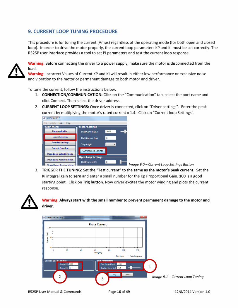
9. CURRENT LOOP TUNING PROCEDURE This procedure is for tuning the current (Amps) regardless of the operating mode (for both open and closed loop). In order to drive the motor properly, the current loop parameters KP and KI must be set correctly. The R525P user interface provides a tool to set PI parameters and test the current loop response. Warning: Before connecting the driver to a power supply, make sure the motor is disconnected from the load. Warning: Incorrect Values of Current KP and KI will result in either low performance or excessive noise and vibration to the motor or permanent damage to both motor and driver. To tune the current, follow the instructions below.
1. CONNECTION/COMMUNICATION: Click on the “Communication” tab, select the port name and click Connect. Then select the driver address.
2. CURRENT LOOP SETTINGS: Once driver is connected, click on “Driver settings”. Enter the peak current by multiplying the motor’s rated current x 1.4. Click on “Current loop Settings”.
Image 9.0 – Current Loop Settings Button 3. TRIGGER THE TUNING: Set the “Test current” to the same as the motor’s peak current. Set the
Ki integral gain to zero and enter a small number for the Kp Proportional Gain. 100 is a good starting point. Click on Trig button. Now driver excites the motor winding and plots the current response. Warning: Always start with the small number to prevent permanent damage to the motor and driver.
Image 9.1 – Current Loop Tuning
1
2 3
R525P User Manual & Commands Page 16 of 49 12/8/2014 Version 1.0
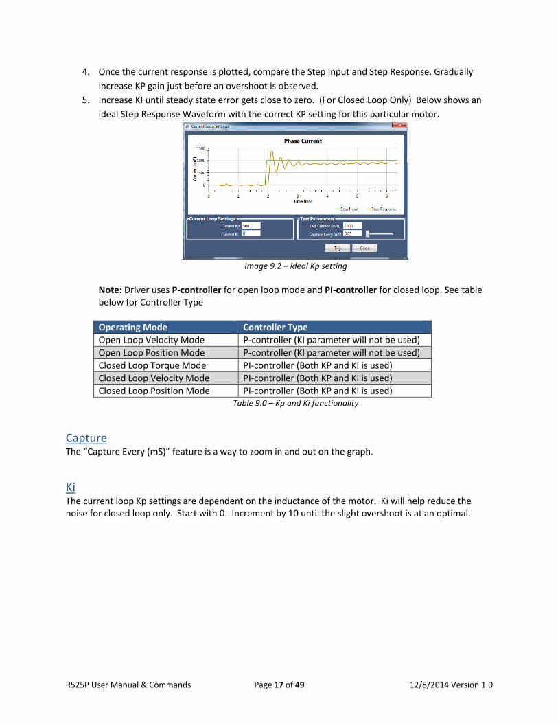
4. Once the current response is plotted, compare the Step Input and Step Response. Gradually increase KP gain just before an overshoot is observed.
5. Increase KI until steady state error gets close to zero. (For Closed Loop Only) Below shows an ideal Step Response Waveform with the correct KP setting for this particular motor.
Image 9.2 – ideal Kp setting
Note: Driver uses P-controller for open loop mode and PI-controller for closed loop. See table below for Controller Type Operating Mode Controller Type Open Loop Velocity Mode P-controller (KI parameter will not be used) Open Loop Position Mode P-controller (KI parameter will not be used) Closed Loop Torque Mode PI-controller (Both KP and KI is used) Closed Loop Velocity Mode PI-controller (Both KP and KI is used) Closed Loop Position Mode PI-controller (Both KP and KI is used)
Table 9.0 – Kp and Ki functionality
Capture The “Capture Every (mS)” feature is a way to zoom in and out on the graph.
Ki The current loop Kp settings are dependent on the inductance of the motor. Ki will help reduce the noise for closed loop only. Start with 0. Increment by 10 until the slight overshoot is at an optimal.
R525P User Manual & Commands Page 17 of 49 12/8/2014 Version 1.0
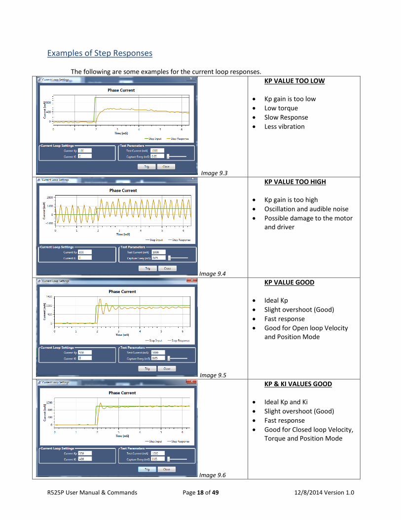
Examples of Step Responses The following are some examples for the current loop responses.
Image 9.3
KP VALUE TOO LOW
• Kp gain is too low • Low torque • Slow Response • Less vibration
Image 9.4
KP VALUE TOO HIGH
• Kp gain is too high • Oscillation and audible noise • Possible damage to the motor
and driver
Image 9.5
KP VALUE GOOD
• Ideal Kp • Slight overshoot (Good) • Fast response • Good for Open loop Velocity
and Position Mode
Image 9.6
KP & KI VALUES GOOD
• Ideal Kp and Ki • Slight overshoot (Good) • Fast response • Good for Closed loop Velocity,
Torque and Position Mode
R525P User Manual & Commands Page 18 of 49 12/8/2014 Version 1.0
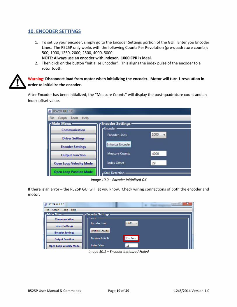
10. ENCODER SETTINGS
1. To set up your encoder, simply go to the Encoder Settings portion of the GUI. Enter you Encoder Lines. The R525P only works with the following Counts Per Revolution (pre-quadrature counts): 500, 1000, 1250, 2000, 2500, 4000, 5000. NOTE: Always use an encoder with indexer. 1000 CPR is ideal.
2. Then click on the button “Initialize Encoder”. This aligns the index pulse of the encoder to a rotor tooth.
Warning: Disconnect load from motor when initializing the encoder. Motor will turn 1 revolution in order to initialize the encoder.
After Encoder has been initialized, the “Measure Counts” will display the post-quadrature count and an Index offset value.
Image 10.0 – Encoder Initialized OK
If there is an error – the R525P GUI will let you know. Check wiring connections of both the encoder and motor.
Image 10.1 – Encoder Initialized Failed
R525P User Manual & Commands Page 19 of 49 12/8/2014 Version 1.0
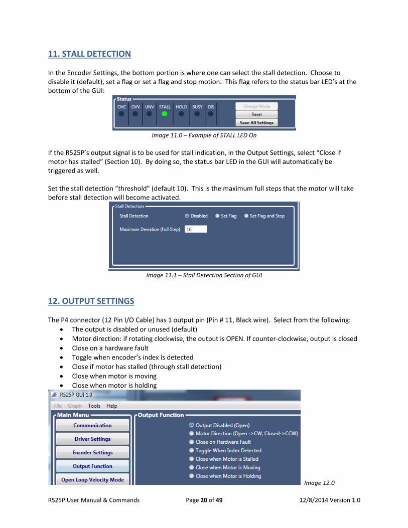
11. STALL DETECTION In the Encoder Settings, the bottom portion is where one can select the stall detection. Choose to disable it (default), set a flag or set a flag and stop motion. This flag refers to the status bar LED’s at the bottom of the GUI:
Image 11.0 – Example of STALL LED On
If the R525P’s output signal is to be used for stall indication, in the Output Settings, select “Close if motor has stalled” (Section 10). By doing so, the status bar LED in the GUI will automatically be triggered as well. Set the stall detection “threshold” (default 10). This is the maximum full steps that the motor will take before stall detection will become activated.
Image 11.1 – Stall Detection Section of GUI
12. OUTPUT SETTINGS The P4 connector (12 Pin I/O Cable) has 1 output pin (Pin # 11, Black wire). Select from the following:
• The output is disabled or unused (default) • Motor direction: if rotating clockwise, the output is OPEN. If counter-clockwise, output is closed • Close on a hardware fault • Toggle when encoder’s index is detected • Close if motor has stalled (through stall detection) • Close when motor is moving • Close when motor is holding
Image 12.0
R525P User Manual & Commands Page 20 of 49 12/8/2014 Version 1.0
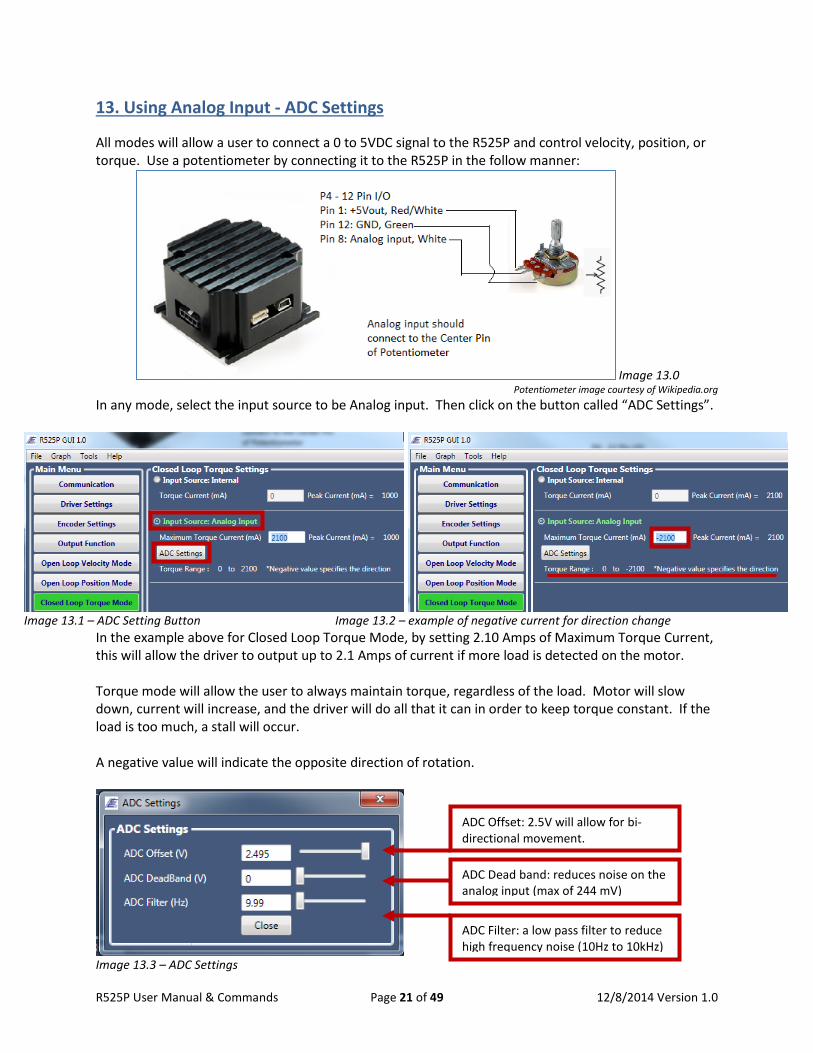
13. Using Analog Input - ADC Settings All modes will allow a user to connect a 0 to 5VDC signal to the R525P and control velocity, position, or torque. Use a potentiometer by connecting it to the R525P in the follow manner:
Image 13.0 Potentiometer image courtesy of Wikipedia.org
In any mode, select the input source to be Analog input. Then click on the button called “ADC Settings”.
Image 13.1 – ADC Setting Button Image 13.2 – example of negative current for direction change
In the example above for Closed Loop Torque Mode, by setting 2.10 Amps of Maximum Torque Current, this will allow the driver to output up to 2.1 Amps of current if more load is detected on the motor. Torque mode will allow the user to always maintain torque, regardless of the load. Motor will slow down, current will increase, and the driver will do all that it can in order to keep torque constant. If the load is too much, a stall will occur. A negative value will indicate the opposite direction of rotation.
Image 13.3 – ADC Settings
ADC Offset: 2.5V will allow for bi-directional movement.
ADC Dead band: reduces noise on the analog input (max of 244 mV)
ADC Filter: a low pass filter to reduce high frequency noise (10Hz to 10kHz)
R525P User Manual & Commands Page 21 of 49 12/8/2014 Version 1.0
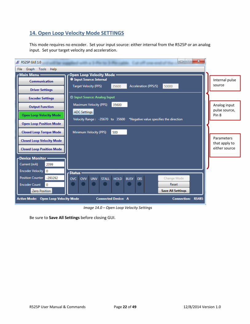
14. Open Loop Velocity Mode SETTINGS This mode requires no encoder. Set your input source: either internal from the R525P or an analog input. Set your target velocity and acceleration.
Image 14.0 – Open Loop Velocity Settings
Be sure to Save All Settings before closing GUI.
Internal pulse source
Analog input pulse source, Pin 8
Parameters that apply to either source
R525P User Manual & Commands Page 22 of 49 12/8/2014 Version 1.0
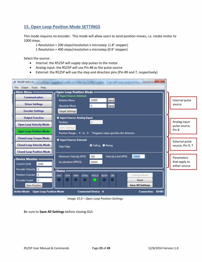
15. Open Loop Position Mode SETTINGS This mode requires no encoder. This mode will allow users to send position moves, i.e. rotate motor to 1000 steps. 1 Revolution = 200 steps/revolution x microstep (1.8° stepper) 1 Revolution = 400 steps/revolution x microstep (0.9° stepper) Select the source:
• Internal: the R525P will supply step pulses to the motor • Analog input: the R525P will use Pin #8 as the pulse source • External: the R525P will use the step and direction pins (Pin #9 and 7, respectively)
Image 15.0 – Open Loop Position Settings
Be sure to Save All Settings before closing GUI.
Internal pulse source
Analog input pulse source, Pin 8
Parameters that apply to either source
External pulse source, Pin 9, 7
R525P User Manual & Commands Page 23 of 49 12/8/2014 Version 1.0
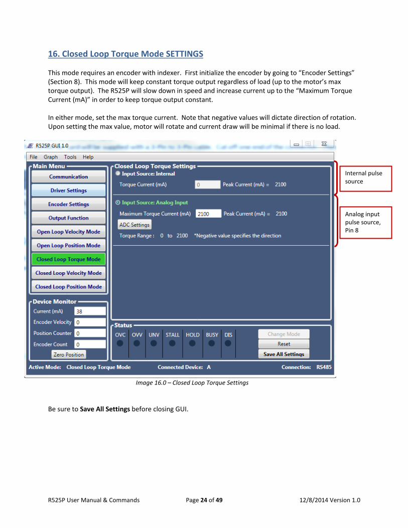
16. Closed Loop Torque Mode SETTINGS This mode requires an encoder with indexer. First initialize the encoder by going to “Encoder Settings” (Section 8). This mode will keep constant torque output regardless of load (up to the motor’s max torque output). The R525P will slow down in speed and increase current up to the “Maximum Torque Current (mA)” in order to keep torque output constant. In either mode, set the max torque current. Note that negative values will dictate direction of rotation. Upon setting the max value, motor will rotate and current draw will be minimal if there is no load.
Image 16.0 – Closed Loop Torque Settings
Be sure to Save All Settings before closing GUI.
Internal pulse source
Analog input pulse source, Pin 8
R525P User Manual & Commands Page 24 of 49 12/8/2014 Version 1.0
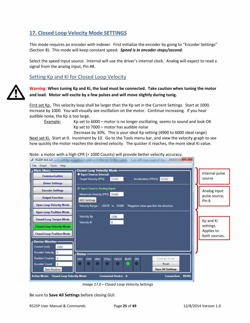
17. Closed Loop Velocity Mode SETTINGS This mode requires an encoder with indexer. First initialize the encoder by going to “Encoder Settings” (Section 8). This mode will keep constant speed. Speed is in encoder steps/second. Select the speed input source. Internal will use the driver’s internal clock. Analog will expect to read a signal from the analog input, Pin #8.
Setting Kp and Ki for Closed Loop Velocity
Warning: When tuning Kp and Ki, the load must be connected. Take caution when tuning the motor and load. Motor will excite by a few pulses and will move slightly during tunig.
First set Kp. This velocity loop shall be larger than the Kp set in the Current Settings. Start at 1000. Increase by 1000. You will visually see oscillation on the motor. Continue increasing. If you hear audible noise, the Kp is too large. Example: Kp set to 6000 – motor is no longer oscillating, seems to sound and look OK Kp set to 7000 – motor has audible noise Decrease by 30%. This is your ideal Kp setting (4900 to 6000 ideal range) Next set Ki. Start at 0. Increment by 10. Go to the Tools menu bar, and view the velocity graph to see how quickly the motor reaches the desired velocity. The quicker it reaches, the more ideal Ki value. Note: a motor with a high CPR (> 1000 Counts) will provide better velocity accuracy.
Image 17.0 – Closed Loop Velocity Settings
Be sure to Save All Settings before closing GUI.
Internal pulse source
Analog input pulse source, Pin 8
Kp and Ki settings. Applies to both sources.
R525P User Manual & Commands Page 25 of 49 12/8/2014 Version 1.0
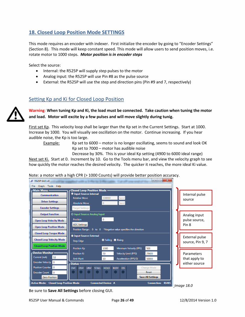
18. Closed Loop Position Mode SETTINGS This mode requires an encoder with indexer. First initialize the encoder by going to “Encoder Settings” (Section 8). This mode will keep constant speed. This mode will allow users to send position moves, i.e. rotate motor to 1000 steps. Motor position is in encoder steps Select the source:
• Internal: the R525P will supply step pulses to the motor • Analog input: the R525P will use Pin #8 as the pulse source • External: the R525P will use the step and direction pins (Pin #9 and 7, respectively)
Setting Kp and Ki for Closed Loop Position
Warning: When tuning Kp and Ki, the load must be connected. Take caution when tuning the motor and load. Motor will excite by a few pulses and will move slightly during tunig.
First set Kp. This velocity loop shall be larger than the Kp set in the Current Settings. Start at 1000. Increase by 1000. You will visually see oscillation on the motor. Continue increasing. If you hear audible noise, the Kp is too large. Example: Kp set to 6000 – motor is no longer oscillating, seems to sound and look OK Kp set to 7000 – motor has audible noise Decrease by 30%. This is your ideal Kp setting (4900 to 6000 ideal range) Next set Ki. Start at 0. Increment by 10. Go to the Tools menu bar, and view the velocity graph to see how quickly the motor reaches the desired velocity. The quicker it reaches, the more ideal Ki value. Note: a motor with a high CPR (> 1000 Counts) will provide better position accuracy.
Image 18.0 Be sure to Save All Settings before closing GUI.
Internal pulse source
Analog input pulse source, Pin 8
Parameters that apply to either source
External pulse source, Pin 9, 7
R525P User Manual & Commands Page 26 of 49 12/8/2014 Version 1.0
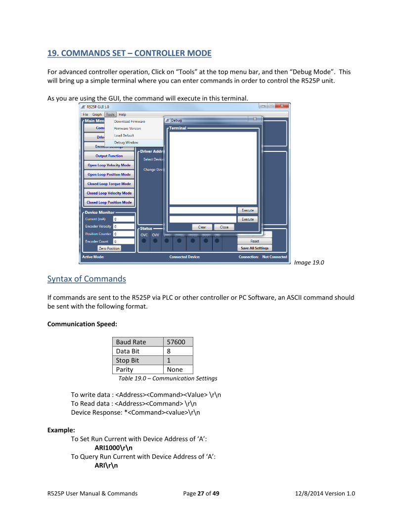
19. COMMANDS SET – CONTROLLER MODE For advanced controller operation, Click on “Tools” at the top menu bar, and then “Debug Mode”. This will bring up a simple terminal where you can enter commands in order to control the R525P unit. As you are using the GUI, the command will execute in this terminal.
Image 19.0
Syntax of Commands
If commands are sent to the R525P via PLC or other controller or PC Software, an ASCII command should be sent with the following format. Communication Speed:
Baud Rate 57600 Data Bit 8 Stop Bit 1 Parity None
Table 19.0 – Communication Settings To write data : <Address><Command><Value> \r\n To Read data : <Address><Command> \r\n
Device Response: *<Command><value>\r\n Example: To Set Run Current with Device Address of ‘A’: ARI1000\r\n To Query Run Current with Device Address of ‘A’: ARI\r\n
R525P User Manual & Commands Page 27 of 49 12/8/2014 Version 1.0
Each command will be explained in detail in the following pages. The examples always assume that your device address is ‘A’. For the command range, we denote as [min:max] but if there are specific values then we denote as [1,2,3,4]
AC – Acceleration / Deceleration Description: Sets a trapezoidal motion profile. Acceleration is equal to deceleration. Value is in Pulse per Second Square. Related Commands: PM, AP, TV, VL, VM Related Mode: Velocity/Position Mode Command Syntax: <address>AC<value> Response: *AC<value> Command Range: [1:500000] Default Value: 5000 Example: AAC10000 ‘Set acceleration to 10,000 AVL51200 ‘1 RPS for a 1.8 degree motor, at 256 microstepping APM51200 ‘Move the motor 51200 steps, or 1 full revolution
AD – ADC Hysteresis (Dead Band) Description: Sets the ADC hysteresis (Dead Band). Each increment is equal to 5 millivolts Related Commands: AO, AF Command Syntax: <address>AD<value> Response: *AD<value> Command Range: [0: 50] Default Value: 0 Example: AAD5 ‘Set the ADC Hysteresis to 25mV
AF – ADC Filter Description: Sets the cut off frequency of the digital Low pass filter for analog input. The cut off frequency can be calculated from the following equation: Cuff of Frequency = 10000
1001−𝐴𝐴𝐴𝐴
Related Commands: AO, AF Command Syntax: <address>AF<value> Response: *AF<value> Command Range: [0: 1000] Default Value: 0 Example: AAF747 ‘Set the cut off frequency to 39 Hz
R525P User Manual & Commands Page 28 of 49 12/8/2014 Version 1.0
AH – Anti Hunt (Position Dead Band) Description: Sets the target dead band in closed loop position mode to prevent oscillation when motor reaches the target Related Commands: AP, PM Command Syntax: <address>AH<value> Response: *AH<value> Command Range: [0: 100] Default Value: 10 Example: AAH20 ‘Set anti-hunt dead band to 20 encoder counts.
AO – ADC Offset Description: Sets the ADC offset. ADC Offset sets the range of ADC input. ADC range can be calculated from the following equation:
Target_Min = Target_Max[1 +1024 × [AnalogIn
5 − 1]1024 − ADC_Offset
]
ADC Range= [Target_Min : Target_Max] where AnalogIn =[0:5] Volts Target_Max= Target Velocity “TV” in velocity mode Target_Max= Target Torque “ST” in Torque mode Target_Max= Target Position “TA” in Position mode Related Commands: AO, AF, TA, ST, TV Command Syntax: <address>AO<value> Response: *AO<value> Command Range: [0: 512] Default Value: 0 Example: ADM0 ‘Set Mode to Open loop Velocity mode ADI1 ‘Set Input source to Analog input AAO512 ‘Set ADC offset to 512
ATV10000 ‘Set Max velocity to 10000 pulse/sec Set the ADC range from [-10000:10000] pulse/sec
R525P User Manual & Commands Page 29 of 49 12/8/2014 Version 1.0
AP – Move to Absolute Position Description: Moves the motor to an absolute position. AP unit is number of steps in open loop mode. In closed loop AP unit is Encoder counts (Post Quadrature). Related Commands: ZP Command Syntax: <address>AP<value> Response: *AP<value> Command Range: [-2147483647: 2147483647] Default Value: 0 Example: AAP1000 ‘Move motor to absolute position 1000 AAP0 ‘Moves motor to absolute position 0
CI – Current loop KI Parameter Description: Sets the KI parameter of Current Loop Related Commands: CP, RI Command Syntax: <address>CI<value> Response: *CI<value> Command Range: [0: 32767] Default Value: 10 Example: ACI20 ‘Set the KI parameter to 20
CP – Current loop KP Parameter Description: Sets the KP parameter of Current Loop Related Commands: CI, RI Command Syntax: <address>CP<value> Response: *CP<value> Command Range: [0: 32767] Default Value: 500 Example: ACP800 ‘Set the KP parameter to 800
R525P User Manual & Commands Page 30 of 49 12/8/2014 Version 1.0
CS – Clear Stall Flag Description: Clears the stall Flag. Related Commands: ES, MD Command Syntax: <address>CS<value> Response: *CS Command Range: N/A Default Value: N/A Example: ACS ‘Reset Stall Flag
DI – Drive Input Source Description: Selects the Driver’s input command source. Depending on the mode, Torque, Velocity, and position, commands can be set internally or externally. Command Open Loop Mode Closed Loop Mode DI=0 External Source. Step/Direction
(Position mode only) External Source. Step/Direction (Position mode only)
DI=1 Velocity and position can be set using Analog input
Torque, Velocity and position can be controlled via Analog input
DI=2 Velocity and position can be set using RS485 or USB
Torque, Velocity and position can be controlled via RS485 or USB
Table 19.1 – Drive Input Source
Related Commands: DM, TV, ST, TA, SE Command Syntax: <address>DI<value> Response: *DI<value> Command Range: [0:2] Default Value: 0 Example: ADI0 ‘Set Drive input source to use external inputs.
R525P User Manual & Commands Page 31 of 49 12/8/2014 Version 1.0
DM – Drive Mode Description: Selects the Driver Mode. Command Open Loop Mode DM=0 Open Loop Velocity Mode DM=1 Open loop Position Mode DM=2 Closed Loop Torque Mode DM=3 Closed Loop Velocity Mode DM=4 Closed Loop Position Mode Table 19.2 – Drive Mode Related Commands: DI Command Syntax: <address>DM<value> Response: *DM<value> Command Range: [0: 4] Default Value: 1 Example: ADM0 ‘Set drive mode to open Loop velocity mode
EA– Align Encoder Description: Tests the encoder and detects the index offset from the rotor. By issuing the EA command, the motor will turn one full revolution. This command must be issued one time after encoder installation. This command will return the post quadrature count of the encoder (For Example for 1000 Line Encoder, EA will return 4000 Counts). Related Commands: EO, EL Command Syntax: <address>EA<value> Response: *EA<value> Command Range: N/A Default Value: N/A Example: AEA ‘Test and align encoder.
EL– Encoder Line Description: Sets the Encoder Line. This tells the R525P what encoder count is mounted to your motor. Related Commands: EO, EA Command Syntax: <address>EA<value> Response: *EL<value> Command Range: 500, 1000, 1250, 2000, 2500, 4000, 5000 Default Value: N/A Example: AEL1000 ‘Tells the driver that 1000 Line Encoder is mounted on the back to motor.
R525P User Manual & Commands Page 32 of 49 12/8/2014 Version 1.0
EO– Encoder Index Offset Description: Sets the Encoder index offset respect to rotor teeth. This variable will be set automatically via “EA” Command for bi-directional motion. Motor speed can be optimized for Uni-directional by adjusting EO manually. Related Commands: EL, EA Command Syntax: <address>EO<value> Response: *EO<value> Command Range: [-100: 100] Default Value: N/A Example: AEO60 ‘Set Encoder offset to 60.
ES– Enable Stall Detection Description: Stall detection can be enabled by setting ES to 1 or 2. Stall detection threshold can be set via “MD” command. ES=1, sets the Status Flag when motor stalls, and ES=2 sets the flag and stops the motor. Motor can be reinitialized by issuing “CS” command. Related Commands: MD, CS Command Syntax: <address>ES<value> Response: *ES<value> Command Range: [0: 2] Default Value: 0 Example: AES2 ‘Set the flag and stop motor if motor stalled.
FR– Firmware Version Description: Returns Firmware Version Related Commands: None Command Syntax: <address>FR Response: *FR<Firmware version> Command Range: N/A Default Value: R525P_V100 Example: AFR ‘Get firmware Version
R525P User Manual & Commands Page 33 of 49 12/8/2014 Version 1.0

GA– Go to Position A Description: Commands the motor to move to Position “A” in position mode. Preset position can be set with “TA” command. Related Commands: TA, PM, AP Command Syntax: <address>GA Response: *GA< value > Command Range: N/A Default Value: N/A Example: AGA ‘Move motor to Position “A”
GB– Go to Position B Description: Commands the motor to move to Position “B” in position mode. Preset position can be set with “TB” command. Related Commands: TB, PM, AP Command Syntax: <address>GB Response: *GB< value > Command Range: N/A Default Value: N/A Example: AGB ‘Move motor to Position “B”
GC– Go to Position C Description: Commands the motor to move to Position “C” in position mode. Preset position can be set with “TC” command. Related Commands: TC, PM, AP Command Syntax: <address>GC Response: *GC< value > Command Range: N/A Default Value: N/A Example: AGC ‘Move motor to Position “C”
R525P User Manual & Commands Page 34 of 49 12/8/2014 Version 1.0
GD– Go to Position D Description: Commands the motor to move to Position “D” in position mode. Preset position can be set with “TD” command. Related Commands: TD, PM, AP Command Syntax: <address>GD Response: *GD< value > Command Range: N/A Default Value: N/A Example: AGD ‘Move motor to Position “D”
GE– Go to Position E Description: Commands the motor to move to Position “E” in position mode. Preset position can be set with “TE” command. Related Commands: TE, PM, AP Command Syntax: <address>GE Response: *GE< value > Command Range: N/A Default Value: N/A Example: AGE ‘Move motor to Position “E”
GF– Go to Position F Description: Commands the motor to move to Position “F” in position mode. Preset position can be set with “TF” command. Related Commands: TF, PM, AP Command Syntax: <address>GF Response: *GF<value> Command Range: N/A Default Value: N/A Example: AGF ‘Move motor to Position “F”
R525P User Manual & Commands Page 35 of 49 12/8/2014 Version 1.0
HI– Hold Current Description: Sets motor’s hold current when motor is stopped. Hold current can be set on scale of 0 to 100% of run current. Related Commands: RI, HT Command Syntax: <address>HI Response: *HI<value> Command Range: [0:100] % Default Value: 50 Example: AHI50 ‘Set hold current to 50% of run current.
HT– Hold Timeout Description: Sets the time interval in milliseconds after any motor movement, before the motor current is changed from Run to Hold Current. Related Commands: RI, HI Command Syntax: <address>HT Response: *HT<value> Command Range: [100:5000] Default Value: 1000 Example: AHT500 ‘Switch to hold current 500 milliseconds after motor stopped
LD– Load Defaults Description: Loads and Saves default factory settings. Related Commands: None Command Syntax: <address>LD Response: *LD Command Range: N/A Default Value: N/A Example: ALD ‘Load and save default settings.
R525P User Manual & Commands Page 36 of 49 12/8/2014 Version 1.0
MA– Module Address Description: Reads or sets the drive address (A-Z). The value read or entered is the decimal value of the ASCII character designated as the unit address. (65 = ‘A’ and 90 = ‘Z’).The change to a new address is immediate, in that the command response will use the new address Related Commands: None Command Syntax: <address>MA<value> Response: *MA<value> Command Range: [65:90] Default Value: 65 Example: AMA66 ‘Set the Address to B (66= ‘B’).
MD – Stall Detection Maximum Deviation Description: Sets the maximum deviation in “full step” for stall detection. Driver uses encoder to compare the actual position to commanded position to detect if motor is stalled. If “MD” is set to a small value, Stall flag can be set during acceleration or deceleration. Related Commands: ES, EL, OE, CS Command Syntax: <address>MD<value> Response: *MD<value> Command Range: [0: 5000] Default Value: 10 Example: AMD100 ‘Set the maximum deviation to 100 full steps
MV – Minimum Velocity Description: Sets the minimum velocity of trapezoidal motion Related Commands: VL, TV, AP, MV Command Syntax: <address>TV<value> Response: *VM<value> Command Range: [100: 15000] Default Value: 1500 Example: AMV2000 ‘Set the minimum velocity to 2000
R525P User Manual & Commands Page 37 of 49 12/8/2014 Version 1.0
OE– Output Enable Description: Sets the output pin action according to the table below. Command Action OE=0 Output Disabled. (Pulled High) OE=1 Motor Direction OE=2 Low when over voltage, under voltage or phase over current detected. OE=3 Toggles at encoder index OE=4 Low when motor is stalled OE=5 Low when motor is moving OE=6 Low when motor is holding
Table 19.3 - Outputs Related Commands: ES, CS Command Syntax: <address>OE<value> Response: *OE<value>. Command Range: [0:6] Default Value: 0 Example: AOE5 ‘Pull the output to low state when motor is moving.
PI – Position Loop KI Parameter Description: Sets the KI parameter of Position Loop controller Related Commands: PP Command Syntax: <address>PI<value> Response: *PI<value> Command Range: [0: 32767] Default Value: 50 Example: API2000 ‘Set the Position KI parameter to 2000
PL – Motor Poles Description: Sets the Motor poles. This command is used for stall detection calculations. “PL” must be set to 200 for 1.8 degree motor and 400 for 0.9 degree motor. Related Commands: ES, MD Command Syntax: <address>PL<value> Response: *PL<value> Command Range: [200 or 400] Default Value: 200 Example: APL200 ‘Set the poles to 200 (1.8 degree motor)
R525P User Manual & Commands Page 38 of 49 12/8/2014 Version 1.0
PM – Relative Move Description: Commands a ‘Relative Move’ in Position mode, using an approximately trapezoidal profile. The initial velocity is defined by ‘Minimum Velocity’ “MV”; the profile ramp is defined by ‘Acceleration’ “AC”, and the ‘Constant Velocity’ step rate by ‘Velocity Limit’ “VL”. Related Commands: AP Command Syntax: <address>PM<value> Response: *PM<value> Command Range: [-2147483647: 2147483647] Default Value: N/A Example: APM20000 ‘move the motor 20000 steps
PP – Position Loop KP Parameter Description: Sets the KP parameter of Position Loop controller Related Commands: PI Command Syntax: <address>PP<value> Response: *PP<value> Command Range: [0: 32767] Default Value: 1000 Example: APP5000 ‘Set the Position KP parameter to 5000
QE– Query Encoder Description: Read and returns encoder counts (Post Quadrature counts). Related Commands: EL, ZE, AP, PM Command Syntax: <address>QE<value> Response: *QE<value> Command Range: [-2147483647: 2147483647] Default Value: Zero at Start up Example: AQE ‘Get encoder position in post Quadrature (4X).
R525P User Manual & Commands Page 39 of 49 12/8/2014 Version 1.0
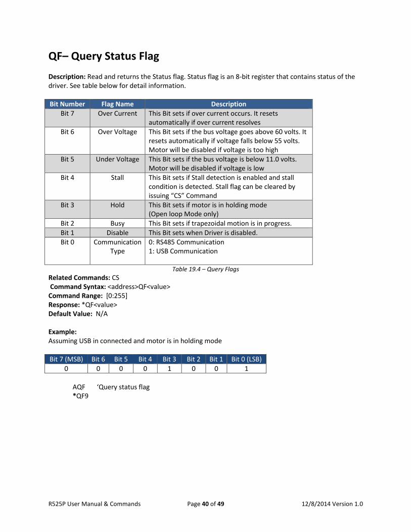
QF– Query Status Flag Description: Read and returns the Status flag. Status flag is an 8-bit register that contains status of the driver. See table below for detail information. Bit Number Flag Name Description
Bit 7 Over Current This Bit sets if over current occurs. It resets automatically if over current resolves
Bit 6 Over Voltage This Bit sets if the bus voltage goes above 60 volts. It resets automatically if voltage falls below 55 volts. Motor will be disabled if voltage is too high
Bit 5 Under Voltage This Bit sets if the bus voltage is below 11.0 volts. Motor will be disabled if voltage is low
Bit 4 Stall This Bit sets if Stall detection is enabled and stall condition is detected. Stall flag can be cleared by issuing “CS” Command
Bit 3 Hold This Bit sets if motor is in holding mode (Open loop Mode only)
Bit 2 Busy This Bit sets if trapezoidal motion is in progress. Bit 1 Disable This Bit sets when Driver is disabled. Bit 0 Communication
Type 0: RS485 Communication 1: USB Communication
Table 19.4 – Query Flags Related Commands: CS Command Syntax: <address>QF<value> Command Range: [0:255] Response: *QF<value> Default Value: N/A Example: Assuming USB in connected and motor is in holding mode Bit 7 (MSB) Bit 6 Bit 5 Bit 4 Bit 3 Bit 2 Bit 1 Bit 0 (LSB)
0 0 0 0 1 0 0 1
AQF ‘Query status flag *QF9
R525P User Manual & Commands Page 40 of 49 12/8/2014 Version 1.0
QP– Query Position Counter Description: Read and returns the absolute position from internal position counter. Related Commands: AP, PM, ZP Command Syntax: <address>QP<value> Response: *QP<value> Command Range: [-2147483647: 2147483647] Default Value: Zero at Start up Example: AQP ‘Query the position from position counter.
QT– Query Torque Description: Read and returns the Torque current. In open loop torque current is the peak coil current set by “RI” when motor is running or hold current when motor is stopped. In closed loop, torque current is the RMS value of Phase A and B currents. Negative sign indicates direction of the motor. Related Commands: RI, HI, ST Command Syntax: <address>QT<value> Response: *QT<value> Command Range: [-5000: 5000] in milliamps Default Value: N/A Example: AQT ‘Query the Torque current.
QV– Query Velocity Description: Read and returns the actual velocity. In open loop Velocity is the frequency that is generated internally to drive the motor in Hertz. In closed loop, Velocity is measured from the encoder (Encoder Counts/Seconds). Related Commands: MV, VL, ST, TV, AP, PM Command Syntax: <address>QV<value> Response: *QV<value> Command Range: [-2147483647: 2147483647] Default Value: N/A Example: AQV ‘Query Actual velocity.
R525P User Manual & Commands Page 41 of 49 12/8/2014 Version 1.0
RI– Run Current Description: Sets the peak current of motor phase when motor is in motion. Related Commands: HI, HT, ST Command Syntax: <address>RI<value> Response: *RI<value> Command Range: [0: 5000] in milliamps Default Value: 1000 Example: ARI2000 ‘Set Run current to 2000 milliamps.
SD – Save Data Description: Stores all parameters to the Flash Memory. Related Commands: LD Command Syntax: <address>SD<value> Response: *SD Command Range: N/A Default Value: N/A Example: ASD ‘Save All Data
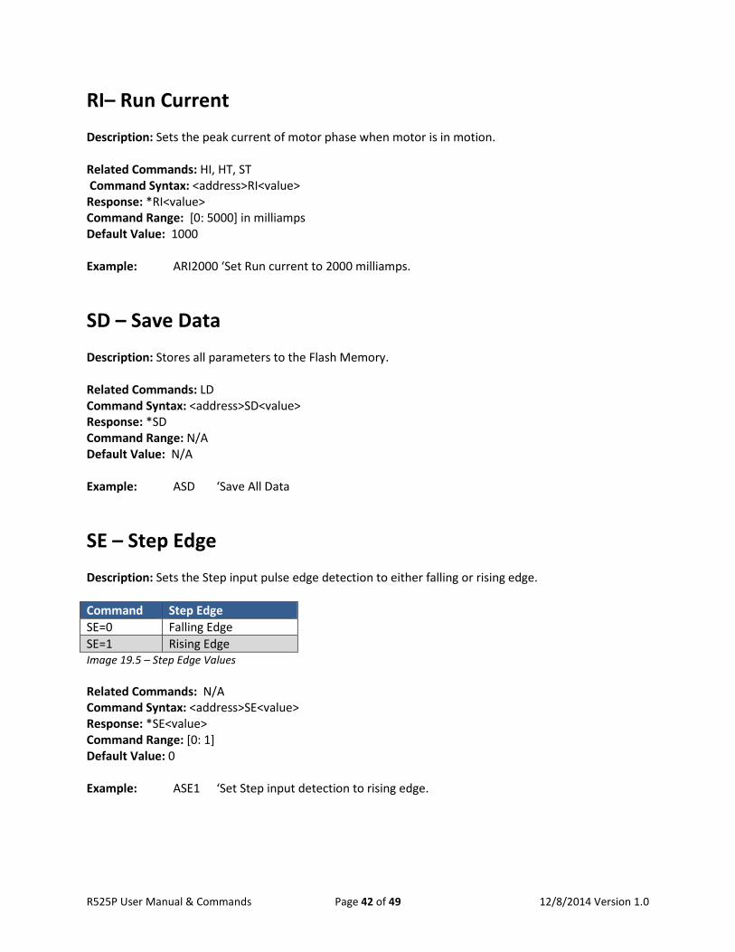
SE – Step Edge Description: Sets the Step input pulse edge detection to either falling or rising edge. Command Step Edge SE=0 Falling Edge SE=1 Rising Edge Image 19.5 – Step Edge Values Related Commands: N/A Command Syntax: <address>SE<value> Response: *SE<value> Command Range: [0: 1] Default Value: 0 Example: ASE1 ‘Set Step input detection to rising edge.
R525P User Manual & Commands Page 42 of 49 12/8/2014 Version 1.0
SR – Step Resolution Description: Sets the step resolution in open loop mode. Related Commands: SS Command Syntax: <address>SR<value> Response: *SR<value> Command Range: {1,2,4,5,8,10,16,25,32,50,64,100,125,128,250,256} Default Value: 256 Example: ASR8 ‘Set Step resolution to 8 micro-step
SS – Step Smoothening Filter Description: Shapes the current waveform to generate smoother edges for smoother motion and less vibration. Smoothening filter can be disabled by setting “SS” command to zero. Related Commands: SR Command Syntax: <address>SS<value> Response: *SS<value> Command Range: [0:127] Default Value: 0 Example: ASS100 ‘Set Step smoothening value to 100
ST – Set Torque Description: Sets the torque current when driver is set to torque mode (DM=2). Related Commands: DM, RI Command Syntax: <address>ST<value> Response: *ST<value> Command Range: [-RI: RI] Default Value: 0 Example: AST1000 ‘Set Step the torque current to 1000 mA
R525P User Manual & Commands Page 43 of 49 12/8/2014 Version 1.0
TA – Target A Description: Sets the target position “A”. Motor can be commanded to move to target position by issuing “GA” command. Related Commands: GA Command Syntax: <address>TA<value> Response: *TA<value> Command Range: [-2147483647: 2147483647] Default Value: 0 Example: ATA10000 ‘Set target position A to 10000
TB – Target B Description: Sets the target position “B”. Motor can be commanded to move to target position by issuing “GB” command. Related Commands: GB Command Syntax: <address>TB<value> Response: *TB<value> Command Range: [-2147483647: 2147483647] Default Value: 0 Example: ATB10000 ‘Set target position B to 10000
TC – Target C Description: Sets the target position “C”. Motor can be commanded to move to target position by issuing “GC” command. Related Commands: GC Command Syntax: <address>TC<value> Response: *TC<value> Command Range: [-2147483647: 2147483647] Default Value: 0 Example: ATC10000 ‘Set target position C to 10000
R525P User Manual & Commands Page 44 of 49 12/8/2014 Version 1.0
TD – Target D Description: Sets the target position “D”. Motor can be commanded to move to target position by issuing “GD” command. Related Commands: GD Command Syntax: <address>TD<value> Response: *TD<value> Command Range: [-2147483647: 2147483647] Default Value: 0 Example: ATD10000 ‘Set target position D to 10000
TE – Target E Description: Sets the target position “E”. Motor can be commanded to move to target position by issuing “GE” command. Related Commands: GE Command Syntax: <address>TE<value> Response: *TE<value> Command Range: [-2147483647: 2147483647] Default Value: 0 Example: ATE10000 ‘Set target position E to 10000
TF – Target F Description: Sets the target position “F”. Motor can be commanded to move to target position by issuing “GF” command. Related Commands: GF Command Syntax: <address>TF<value> Response: *TF<value> Command Range: [-2147483647: 2147483647] Default Value: 0 Example: ATF10000 ‘Set target position F to 10000
R525P User Manual & Commands Page 45 of 49 12/8/2014 Version 1.0
TV – Target Velocity Description: Sets the target velocity in velocity mode. In open loop the target velocity unit is in Hertz. In closed loop, velocity unit is in Encoder Count/Seconds. Negative sign indicates direction of the motor. Related Commands: MV, VL Command Syntax: <address>TV<value> Response: *TV<value> Command Range: [-5000000: 5000000] Default Value: 0 Example: ADM0 ‘Set mode to open loop velocity mode ATV10000 ‘Set target Velocity to 10 KHz in open loop mode
VI – Velocity Loop KI Parameter Description: Sets KI parameter of the Velocity Loop Controller Related Commands: VP Command Syntax: <address>VI<value> Response: *VI<value> Command Range: [0: 32767] Default Value: 0 Example: AVI20 ‘Set the KI parameter of velocity loop to 20
VL – Velocity Limit Description: Sets the maximum velocity that motor can reach in pulse per seconds for open loop and encoder counts per seconds for closed loop. Related Commands: TV, PM, AP Command Syntax: <address>VL<value> Response: *VL<value> Command Range: [100: 5000000] Default Value: 20000 Example: AVL10000 ‘Set the Velocity Limit to 10000
R525P User Manual & Commands Page 46 of 49 12/8/2014 Version 1.0
VP – Velocity Loop KP Parameter Description: Sets KP parameter of Velocity Loop controller Related Commands: VI Command Syntax: <address>VP<value> Command Range: [0: 32767] Response: *VP<value> Default Value: 1000 Example: AVP500 ‘Set the KP parameter to 500
ZP– Zero Position Counter Description: Resets position counter and encoder count. Related Commands: PM, AP Command Syntax: <address>ZP Response: *ZP Command Range: N/A Default Value: N/A Example: AZP ‘Reset position counter and Encoder counts to zero.
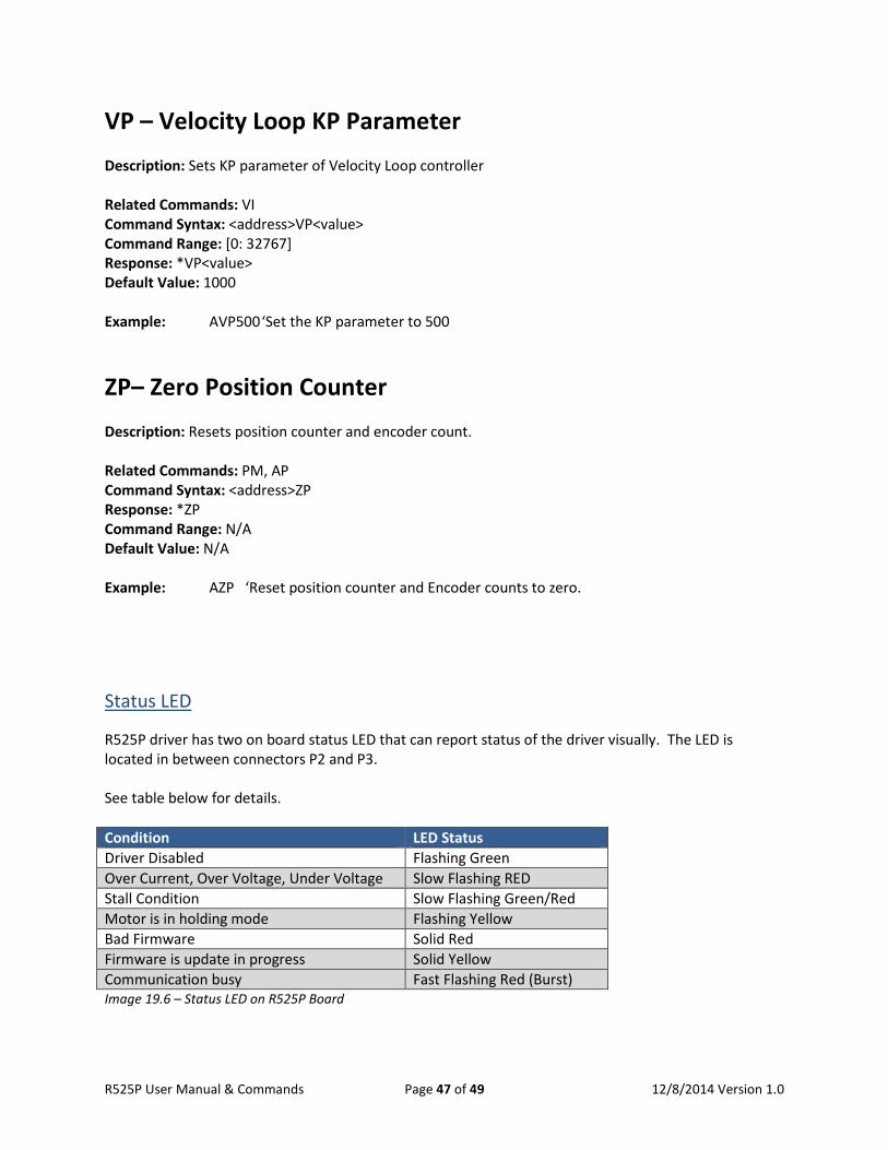
Status LED R525P driver has two on board status LED that can report status of the driver visually. The LED is located in between connectors P2 and P3. See table below for details. Condition LED Status Driver Disabled Flashing Green Over Current, Over Voltage, Under Voltage Slow Flashing RED Stall Condition Slow Flashing Green/Red Motor is in holding mode Flashing Yellow Bad Firmware Solid Red Firmware is update in progress Solid Yellow Communication busy Fast Flashing Red (Burst) Image 19.6 – Status LED on R525P Board
R525P User Manual & Commands Page 47 of 49 12/8/2014 Version 1.0
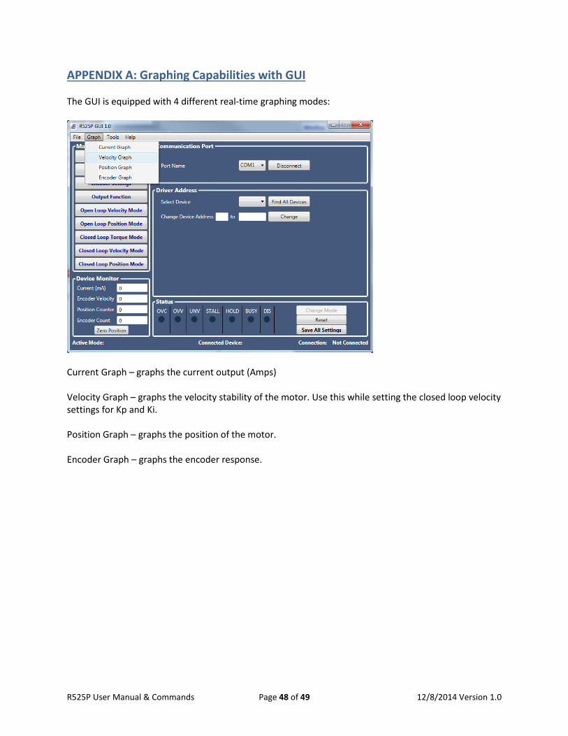
APPENDIX A: Graphing Capabilities with GUI The GUI is equipped with 4 different real-time graphing modes:
Current Graph – graphs the current output (Amps) Velocity Graph – graphs the velocity stability of the motor. Use this while setting the closed loop velocity settings for Kp and Ki. Position Graph – graphs the position of the motor. Encoder Graph – graphs the encoder response.
R525P User Manual & Commands Page 48 of 49 12/8/2014 Version 1.0
APPENDIX B: Example Programming Setting up the Encoder: EL1000 ‘Sets the number of encoder lines EA ‘The R525P aligns the encoder. It counts and returns an actual encoder line. If it returns a negative, motor phase wires should be switched. SD ‘Save Data ZE ‘Reset the encoder position (zero encoder) Setting up Stall Detection: ES1 ‘Enable stall detection. ES2 stops the motor if stall is detected MD50 ‘Sets the maximum encoder deviation in full steps RS ‘Clear the Stall condition Basic Move Command: DM0 DI2 ‘Driver mode should be in velocity or position mode AC1000 ‘Sets the acceleration to 1000 pps² MV1500 ‘Sets the minimum velocity (Starting velocity to 1500 pps) VL30000 ‘Sets the velocity to 30,000 pps TV10000 ‘Sets the velocity for velocity mode. TV should be less than VL DM1 DI2 ‘Driver mode should be in velocity or position mode AC1000 ‘Sets the acceleration to 1000 pps² MV1500 ‘Sets the minimum velocity (starting velocity to 1500 pps) VL30000 ‘Sets the velocity to 30,000 pps PM10000 ‘Move motor to absolute position 10000 PM-20000 ‘Move motor to absolute position -20000 AP0 ‘Move motor to absolute position 0
R525P User Manual & Commands Page 49 of 49 12/8/2014 Version 1.0