Embed Size (px)
Citation preview

Factory Automation
Our policy is one of continued research and development. We therefore reserve the right to amend, without notice, the specifications given in this document. © 2020 Norgren Ltd
01/20en us 8.105.855
Technical features
Technical data R82G
*1) All models shown here are supplied with integrated gauge applicable for flow direction left to right. With flow direction right to left please use the online configurator www.imi-precision.com/air-preparation-configurator or contact Norgren.
> Port size: 1/4” & 3/8” (ISO G/PTF)
> Excelon® Plus design allows in-line installationormodular installationwithother Excelon® Plus products
> Pushtolockadjusting knobwithbuiltintamper resistantfeature
> Easytoreadflushmountedintegrated pressure gauge
asstandard
Medium:Compressed air only
Maximumsupplypressure:290 psi (20 bar)
Outlet pressure ranges:4 to 145 psi, (0.3 to 10 bar)4 to 58 psi, ( 0.3 to 4 bar)10 to 247 psi, (0.7 to 17 bar)
Port size:G1/4, G3/8, 1/4 PTF, 3/8 PTF
Gauge:Integrated as standardGauge port 1/8 as option
DiaphragmType:Relieving
Flow:69 scfm (33 dm3/s) at port size 1/4”,66 scfm (31 dm3/s) at port size 3/8”,inlet pressure 145 psi (10 bar), operating pressure 91 psi (6.3 bar) and a Δp: 14.5 psi (1.0 bar) dropfrom set.
Ambient/Mediatemperature:-4 ... +149ºF (-20 ... +65ºC)Air supply must be dry enoughto avoid ice formation attemperatures below +35°F (+2°C).
Materials:Body: Die cast aluminiumBody covers: ABSBonnet: POM/AluminiumValve: PPElastomers: NBR
R82 — Excelon® Plus Modular System Pressure Regulators
1/4 4 to 145 (0.3 to 10) Knob 0 to 145 psi (0 to 10) 0.50 (0.23) R82G-2AK RMG3/8 4 to 145 (0.3 to 10) Knob 0 to 145 psi (0 to 10) 0.50 (0.23) R82G-3AK-RMG
Symbol Port Size Pressure range Adjustment Integrated gauge Weight lb (kg) Model *1 (PTF) psi (bar) psi (bar)
R82H–H H H– R H HOption selector *1)
SubstituteGR
Substitute23
SubstituteAG
SubstituteK
T*2)
FlowGeneral
Reverse FlowPort size
1/4“3/8“
ThreadformPTF
ISO G parallel Adjustment
Knob T-bar
Gauge Substitute With (fitted integrated gauge) G Without integrated gauge
N but with gauge port 1/8”
Pressure range *3) Substitute 4 to 58 psi (0.3 to 4 bar) F 4 to 145 psi (0.3 to 10 bar) M1 0 to 247 psi (0.7 to 17 bar) S*2)
*3) Outlet pressure can be adjusted to pressures in excess of, and less than, those specified. Do not use these units to control pressures outside of the specified ranges.
*1) All models shown here are applicable for flow direction left to right. With flow direction right to left please use the online configurator www.imi-precision.com/air-preparation-configurator or contact Norgren.
*2) Units with 247 psi outlet pressure range are available only with the T-bar adjustment; therefore substitute T at the 7th position and S at the 9th position. T-bar handle only available with 247 psi option.

Our policy is one of continued research and development. We therefore reserve the right to amend, without notice, the specifications given in this document. © 2020 Norgren Ltd
01/20en us 8.105.855
Warning: Cancer and reproductive harm — www.p65warnings.ca.gov.
Flow characteristics
Inlet pressure: 145 psi (10 bar) Range: 4 to 145 psi (0.3 to 10 bar)Port size: 1/4”
Inlet pressure: 145 psi (10 bar) Range: 4 to 145 psi (0.3 to 10 bar)Port size: 3/8”
OU
TLET
PR
ESSU
RE
100
80
60
40
20
0
AIR FLOW
scfm
dm3/s
bar g
psig
0
2
4
6
0 20 40 60 70 80503010
0 10 20 30
OU
TLET
PR
ESSU
RE
100
80
60
40
20
0
AIR FLOW
scfm
dm3/s
bar g
psig
0
2
4
6
0 20 40 60 70 80503010
0 10 20 30
Our policy is one of continued research and development. We therefore reserve the right to amend, without notice, the specifications given in this document. © 2020 Norgren Ltd
01/20en us 8.105.855
Warning: Cancer and reproductive harm — www.p65warnings.ca.gov.
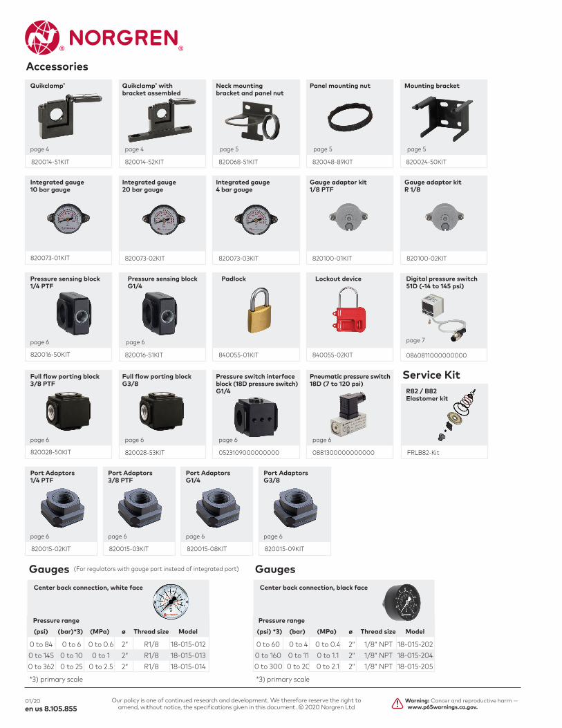
Accessories
820073-01KIT 820073-02KIT 820073-03KIT 820100-01KIT 820100-02KIT
Integrated gauge Integrated gauge Integrated gauge Gauge adaptor kit Gauge adaptor kit10 bar gauge 20 bar gauge 4 bar gauge 1/8 PTF R 1/8
820014-51KIT 820014-52KIT 820068-51KIT 820048-89KIT 820024-50KIT
Quikclamp® Quikclamp®with Neckmounting Panelmountingnut Mountingbracket bracketassembled bracketandpanelnut
page 4 page 4 page 5 page 5 page 5
820016-50KIT 840055-01KIT 840055-02KIT
Pressure sensing block Pressure sensing block Padlock Lockout device1/4 PTF G1/4
page 6 page 6
0860811000000000
page 7
Digital pressure switch51D (-14 to 145 psi)
820028-50KIT 820028-53KIT 0523109000000000 0881300000000000
Fullflowportingblock Fullflowportingblock Pressureswitchinterface Pneumaticpressureswitch3/8 PTF G3/8 block (18D pressure switch) 18D (7 to 120 psi) G1/4
page 6 page 6 page 6 page 6
FRLB82-Kit
Service KitR82 / B82Elastomerkit
(For regulators with gauge port instead of integrated port)
*3) primary scale
Gauges
0 to 84 0 to 6 0 to 0.6 2“ R1/8 18-015-012 0 to 145 0 to 10 0 to 1 2“ R1/8 18-015-013 0 to 362 0 to 25 0 to 2.5 2“ R1/8 18-015-014
Pressure range
(psi) (bar)*3) (MPa) ø Thread size Model
Center back connection, white face
*3) primary scale
Gauges
0 to 60 0 to 4 0 to 0.4 2“ 1/8“ NPT 18-015-202 0 to 160 0 to 11 0 to 1.1 2“ 1/8“ NPT 18-015-204 0 to 300 0 to 20 0 to 2.1 2“ 1/8“ NPT 18-015-205
Pressure range
(psi) *3) (bar) (MPa) ø Thread size Model
Center back connection, black face
820015-02KIT
Port Adaptors1/4 PTF
page 6
820015-03KIT
Port Adaptors3/8 PTF
page 6
820015-08KIT
Port AdaptorsG1/4
page 6
820015-09KIT
Port AdaptorsG3/8
page 6
820016-51KIT

Our policy is one of continued research and development. We therefore reserve the right to amend, without notice, the specifications given in this document. © 2020 Norgren Ltd
01/20en us 8.105.855
Warning: Cancer and reproductive harm — www.p65warnings.ca.gov.
Dimensions
Quikclamp® with wall bracket
AccessoriesQuikclamp®
Main ports 1/4”, 3/8”, (ISO G/PTF)
Gauge port Rc 1/8 for ISO G and 1/8 PTF for PTF main ports
1n
n2
2.3 (58.5)
1.7
(43.
0)
2.14
(54.
5)
4.07
(103
.3)
1.65
(42.
0)1.
53 (3
9.0)
1.5 (38.1)
.47 (12.1)
�
������
��� ��
���
������
��
��� ��
��
�
3.1
(78.
45)
1.4
(35.
65)
4.2
(105
.60)
1.4
(35.
65)
FLOW
1.8 (46.50)
2.2
(56.
00)
1.8 (46.50)
2.2
(56.
00)
1 1
21
1.85 (46.9) .47 (12.1)
1.7
(43.
1)
Dimensions in inches (mm) Projection/Third angle
Our policy is one of continued research and development. We therefore reserve the right to amend, without notice, the specifications given in this document. © 2020 Norgren Ltd
01/20en us 8.105.855
Warning: Cancer and reproductive harm — www.p65warnings.ca.gov.
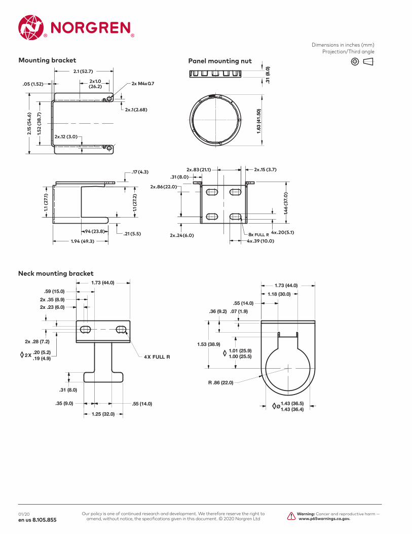
Neckmountingbracket
Panelmountingnut
51
21
33
45
80 51
5746
68
71
58
8.9 15
47
15
58
36
57
66
4
18
29
31
05
58
36
15
2.7
32
53
2
2. 53
1.63
(41.
50)
.31
(8.0
)
Ø
4X FULL R
1.73 (44.0) 1.73 (44.0)
1.43 (36.5)1.43 (36.4)
R .86 (22.0)
1.01 (25.9)1.00 (25.5)
1.18 (30.0)
.36 (9.2) .07 (1.9)
.55 (14.0)
1.53 (38.9)
1.25 (32.0)
.55 (14.0)
.59 (15.0)
.31 (8.0)
.35 (9.0)
2x .35 (8.9)
2x .23 (6.0)
2x .28 (7.2)
.20 (5.2)
.19 (4.9)2X
2.1 (52.7)
.05 (1.52)
2.15
(54.
6)
1.1 (2
7.1)
1.1 (2
7.2)
1.46
(37.
0)
1.52
(38.
7)
2x .1 (2.68)
2x .24 (6.0)
2x .15 (3.7)
.21 (5.5)
.17 (4.3) 2x .83 (21.1).31 (8.0)
4x .39 (10.0)
4x .20(5.1)
2x .86 (22.0)
2x 1.0(26.2)
2x .12 (3.0)
1.94 (49.3)
.94 (23.8)
2x M4x0.7
8x FULL R
Mounting bracket
Dimensions in inches (mm) Projection/Third angle

Our policy is one of continued research and development. We therefore reserve the right to amend, without notice, the specifications given in this document. © 2020 Norgren Ltd
01/20en us 8.105.855
Warning: Cancer and reproductive harm — www.p65warnings.ca.gov.
Pressure sensing block Fullflowportingblock
2X 1.44 (36.6)
.88 (22.3)
1.76 (44.6)
1.97 (50.125).98 (25.12)
1.66 (42.25)
.72 (18.3)1.
5 (3
8.0)
.75 (19.0)
1.12 (28.6)
1.42 (36.0)
.19
(5)
1.18 (30)
1.18
(30)
1.77
(45)18
AC/
1.08 (27.5)
2.83 (72)
1.38 (35)
1.73 (44)
1.25 (32)
1.57
(40)
1.57 (40)
G1/4
Porting block for 18D pressure switch 18D Pressure switch
18DPortingblockand18Dassembled Pipe adaptor
.90 (23.00)
.46 (11.90)
.54 (13.85)
.51 (13.10)
.33 (8.40)
1.03 (26.20)
.45 (11.50)
1.73 (44)
1.26 (32)
1.57 (40)
2.24 (57)
G1/4
1.57
(40)
Dimensions in inches (mm) Projection/Third angle

Our policy is one of continued research and development. We therefore reserve the right to amend, without notice, the specifications given in this document. © 2020 Norgren Ltd
01/20en us 8.105.855
Warning: Cancer and reproductive harm — www.p65warnings.ca.gov.
51D Pressure switch - digital
11.8
(300
.0)
1.22
(31.
0)
1
3
56
4
7
1.22 (31.0)
G1/
8
1.43 (36.50)
1.18
(30.
0)
2
Switch OUT 1, green LED Switch OUT 2, red LED Dustproof protector Connector M12 x 1 Inlet port Alternative inlet port G1/8 plugged Thread for mounting screw
1
2
3
4
5
6
7
Dimensions in inches (mm) Projection/Third angle
WarningThese products are intended for use in industrial compressed air systems only. Do not use these products where pressures and temperatures can exceed those listed under »Technical features/data«. Before using these products with fluids other than those specified, for non-industrial applications, life-support systems or other applications not within published specifications, consult IMI Precision Engineering, Norgren Ltd.
Through misuse, age, or malfunction, components used in fluid power systems can fail in various modes. The system designer is warned to consider the failure
modes of all component parts used in fluid power systems and to provide adequate safeguards to prevent personal injury or damage to equipment in the event of such failure.
System designers must provide a warning to end users in the system instructio-nal manual if protection against a failure mode cannot be adequately provided. System designers and end users are cautioned to review specific warnings found in instruction sheets packed and shipped with these products.