Embed Size (px)
Citation preview

EK-ORA80-UG -001
RA80 DISK DRIVE USER GUIDE
mDmDomo

EK -ORA80- UG -001
RA80 DISK DRIVE USER GUIDE
Digital Equipment Corporation • Colorado Springs, Colorado
First Edition, January 1982
Copyright © 1981 by Digital Equipment Corporation
All Rights Reserved
The material in this manual is for informational purposes and is subject to change without notice.
Digital Equipment Corporation assumes no responsibility for any errors which may appear in this manual.
Printed in U.S.A.
This document was set on DIGITAL's DECset-8000 computerized typesetting system.
• Class A Computing Devices:
Notice: This equipment generates, uses, and may emit radio frequency energy. The equipment has been type tested and found to comply with the limits for a Class A computing device pursuant to Subpart J of Part 15 of FCC Rules, which are designed to provide reasonable protection against such radio frequency interference when operated in a commercial environment. Operation of this equipment in a residential area may cause interference in which case the user at his own expense may be required to take measures to correct the interference.
The following are trademarks of Digital Equipment Corporation, Maynard, Massachusetts:
DEC DECUS DIGITAL Digital Logo PDP UNIBUS VAX
DECnet DECsystem-10 DECSYSTEM-20 DECwriter DIBOL EduSystem lAS MASSBUS
OMNIBUS OS/8 PDT RSTS RSX VMS VT

CHAPTER 1
1.1 1.2 1.3 1.3.1 1.3.2 1.3.3 1.4 1.5 1.6
CHAPTER 2
2.1 2.1.1 2.1.2 2.1.3 2.1.4 2.2 2.2.1 2.2.2 2.2.3
2.3 2.3.1 2.3.2 2.3.2.1 2.3.2.2 2.3.3 2.4 2.4.1 2.4.2 2.4.3 2.4.4
2.4.5 2.4.6
CONTENTS
INTRODUCTION
PURPOSE AND SCOPE ........................................ . GENERAL INFORMATION ..................................... . DRIVE DESCRIPTION ......................................... .
Head Disk Assembly ......................................... . Internal Drive Diagnostics .................................... . Dual-Port Capability ........................................ .
RA80-RELATED DOCUMENTATION ........................... . RA80 SPECIFICATIONS ........................................ . RA80 OPTIONS ................................................ .
INSTALLATION
SITE PREP ARA TION AND PLANNING Environmental Considerations ................................ . Floor Loading .............................................. . Power and Safety Precautions ................................. . AC Power Wiring ........................................... .
EQUIPMENT UNPACKING AND EXTERNAL INSPECTION ..... . Unpacking the System on a Shipping Pallet ..................... . Installing the Leveler Feet .................................... . Removing the Internal Shipping Brackets and
Packing Material ........................................ . RUA80 INSTALLATION ........................................ .
Joining Cabinets ............................................ . SI Cabling Procedure ........................................ .
Internal SI Cabling Procedure ............................ . External SI Cabling Procedure ............................ .
Programming the Drive Unit Address Plug ..................... . RA80 ADD-ON INSTALLATION ............................... ..
Remove the Front Filler Panel ................................ . Install the Slide Assembly .................................... . Mount the RA80 on the Slides ................................ . Remove the Internal Shipping Brackets and
Packing Material ........................................ . Program the Drive Unit Address Plug .......................... . Secure the Electrostatic Discharge Bracket ...................... .
iii
Page
1-1 1-1 1-2 1-3 1-3 1-4 1-4 1-4 1-4
2-1 2-1 2-1 2-1 2-1 2-1 2-2 2-4
2-7 2-10 2-14 2-19 2-19 2-19 2-23 2-23 2-23 2-26 2-32
2-37 2-37 2-37

CHAPTER 2
2.4.7 2.4.8 2.4.9 2.4.10 2.4.11 2.5 2.5.1 2.5.2 2.5.3
CHAPTER 3
3.1 3.1.1 3.1.1.1 3.1.1.2 3.1.1.3 3.1.1.4 3.1.1.5 3.1.2 3.1.3 3.2 3.2.1 3.2.2 3.2.3 3.3 3.3.1 3.3.2 3.3.3
FIGURES
1-1 1-2 1-3 2-1 2-2 2-3 2-4 2-5 2-6 2-7 2-8 2-9
Page
INSTALLATION (Cont)
Install the SI Cables ...................................... ,... 2-38 Mount the I/O Bulkhead ...................................... 2-42 Install the Drive Sequence Cables .......................... '. . . . 2-43 Plug in the AC Power Cord ................................... 2-43 Route and Clamp the Cables. . . . . . . . . . . . . . . . . . . . . . . . . . . . . . . . . . . 2-43
RUA80 CHECKOUT PROCEDURE ............................... 2-48 Applying Power .............................................. 2-48 Drive Checkout Procedure. . . . . . . . . . . . . . . . . . . . . . . . . . . . . . . . . . . . . 2-48 Disk Subsystem Checkout Procedure ........................... 2-48
OPERATING INSTRUCTIONS
OPERATOR CONTROLS AND INDICATORS Front Panel Controls and Indicators ........................... .
RUN/STOP Switch and Indicator ......................... . FAULT Indicator and Reset Switch ....................... . READY Indicator ....................................... . WRITE PROTect Switch and Indicator .................... . Port-Select Switches ..................................... .
Circuit Breakers ............................................. . Front Panel Fault Indications ................................. .
DRIVE OPERATION ........................................... . Spin-Up .................................................... . Spin-Down ................................................. . Removing RA80 Power ...................................... .
CUSTOMER CARE ............................................ . Filter Removal .............................................. . Cleaning ................................................... . Replacement ................................................ .
3-1 3-1 3-1 3-1 3-1 3-1 3-2 3-2 3-4 3-5 3-5 3-5 3-5 3-5 3-5 3-5 3-5
Subsystem Configuration Diagram ........ . . . . . . . . . . . . . . . . . . . . . . . . . . 1-2 RA80 Disk Drive .. . . . . . . . . . . . . . . . . . . . . . . . . . . . . . . . . . . . . . . . . . . . . . . . 1-3 RA80 Dual-Port Configuration .................................... 1-4 RA80 Cabinet AC Plugs .......................................... 2-2 Unpacking a System on a Shipping Pallet ..... . . . . . . . . . . . . . . . . . . . . . . 2-3 Ramp Construction ............................................... 2-4 Shipping Bracket Removal ........................................ 2-5 Installation of Leveler Feet ........................................ 2-6 Adjusting Leveler Feet ............................................ 2-7 Foam Pad Removal .............................................. 2-8 Raising the Drive Logic Chassis .................................... 2-9 HD A Details .................................................... 2-11
IV
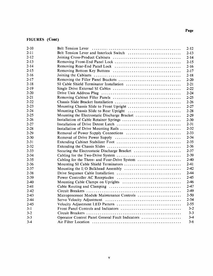
FIG URES (Coot)
2-10 2-11 2-12 2-13 2-14 2-15 2-16 2-17 2-18 2-19 2-20 2-21 2-22 2-23 2-24 2-25 2-26 2-27 2-28 2-29 2-30 2-31 2-32 2-33 2-34 2-35 2-36 2-37 2-38 2-39 2-40 2-41 2-42 2-43 2-44 2-45 3-1 3-2 3-3 3-4
Belt Tension Lever Belt Tension Lever and Interlock Switch ........................... . Joining Cross-Product Cabinets ................................... . Removing Front-End Panel Lock .................................. . Removing Rear-End Panel Lock .................................. . Removing Bottom Key Buttons ................................... . Joining the Cabinets ....... ' ...................................... . Removing the Filler Panel Brackets ................................ . SI Cable Shield Terminator Installation ............................ . Single Drive External SI Cables ................................... . Drive Unit Address Plug ......................................... . Removing Cabinet Filler Panels ................................... . Chassis Slide Bracket Installation .................................. . Mounting Chassis Slide to Front Upright ........................... . Mounting Chassis Slide to Rear Upright ........................... . Mounting the Electrostatic Discharge Bracket ....................... . Installation of Cable Retainer Springs .............................. . Installation of Drive Detent Latch ................................. . Installation of Drive Mounting Rails ............................... . Removal of Power Supply Connections ............................ . Removal of Drive Power Supply .................................. . Extending Cabinet Stabilizer Foot .................... ~ ............ . Extending the Chassis Slides ...................................... . Securing the Electrostatic Discharge Bracket ........................ . Cabling for the Two-Drive System ................................. . Cabling for the Three- and Four-Drive System ...................... . Mounting SI Cable Shield Terminators ............................. . Mounting the 110 Bulkhead Assembly ............................. . Drive Sequence Cable Installation ................................. . Power Controller AC Receptacles ................................. . Mounting Cable Clamps on Uprights .............................. . Cable Routing and Clamping ..................................... . Circuit Breakers ................................................. . Microprocessor Module Maintenance Controls ...................... . Servo Velocity Adjustment ....................................... . Velocity Adjustment LED Pattern ................................. . Front Panel Controls and Indlicators ............................... . Circuit Breakers ................................................. . Operator Control Panel General Fault Indicators .................... . Air Filter Location .............................................. .
v
Page
2-12 2-13 2-14 2-15 2-16 2-17 2-18 2-20 2-21 2-22 2-24 2-25 2-26 2-27 2-28 2-29 2-30 2-31 2-32 2-33 2-34 2-35 2-36 2-37 2-39 2-40 2-41 2-42 2-44 2-45 2-46 2-47 2-49 2-50 2-54 2-55
3-2 3-3 3-4 3-6

TABI.ES
1-1 1-2 2-1
Page
RA80 Specifications .............................................. 1-5 RA80 Options ................................................... 1-8 Drive-Resident Diagnostic Tests ........ ,........................... 2-51
VI
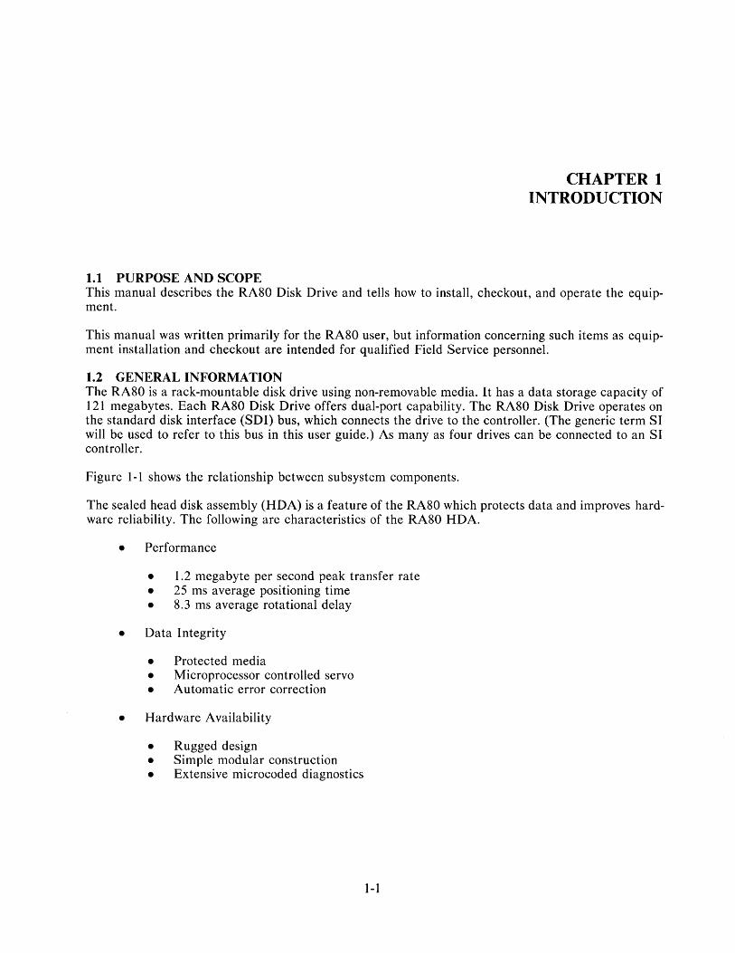
1.1 PURPOSE AND SCOPE
CHAPTER 1 INTRODUCTION
This manual describes the RASO Disk Drive and tells how to install, checkout, and operate the equipment.
This manual was written primarily for the RASO user, but information concerning such items as equipment installation and checkout are intended for qualified Field Service personnel.
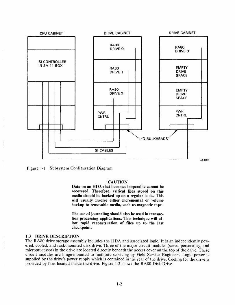
1.2 GENERAL INFORMATION The RASO is a rack-mountable disk drive using non-removable media. It has a data storage capacity of 121 megabytes. Each RASO Disk Drive offers dual-port capability. The RASO Disk Drive operates on the standard disk interface (SDI) bus, which connects the drive to the controller. (The generic term SI will be used to refer to this bus in this user guide.) As many as four drives can be connected to an SI controller.
Figure 1-1 shows the relationship between subsystem components.
The sealed head disk assembly (HDA) is a feature of the RASO which protects data and improves hardware reliability. The following are characteristics of the RASO HDA.
• Performance
• 1.2 megabyte per second peak transfer rate • 25 ms average positioning time • S.3 ms average rotational delay
• Data Integrity
• Protected media • Microprocessor controlled servo • Automatic error correction
• Hardware Availability
• Rugged design • Simple modular construction • Extensive microcoded diagnostics
1-1
CPU CABINET DRIVE CABINET DRIVE CABINET
RASa RAsa DRIVE a DRIVE 3
SI CONTROLLER IN BA-11 BOX
RAsa EMPTY DRIVE 1 DRIVE
SPACE
RAsa EMPTY DRIVE 2 DRIVE
SPACE
PWR r----PWR
CNTRL CNTRL ,....-
I I I r I
~I/O BULKHEADS/
SI CABLES
Figure 1-1 Subsystem Configuration Diagram
'CAUTION Data on an HDA that becomes inoperable cannot be recovered. Therefore, critical files stored on this media should be backed up on a regular basis. This will usually involve either incremental or volume backup to removable media, such as magnetic tape.
The use of journaling should also be used in transaction processing applications. This technique will allow rapid reconstruction of files up to the last checkpoint.
1.3 DRIVE DESCRIPTION
CZ 0560
The RA80 drive storage assembly includes the HDA and associated logic. It is an independently powered, cooled, and rack-mounted disk drive. Three of the major circuit modules (servo, personality, and microprocessor) in the drive are located directly beneath the access cover on the top of the drive. These circuit modules are hinge-mounted to facilitate servicing by Field Service Engineers. Logic power is supplied by the drive's power supply which is contained in the rear of the drive. Cooling for the drive is provided by fans located inside the drive. Figure 1-2 shows the RA80 Disk Drive.
1-2

CZ-0561
Figure 1-2 RA80 Disk Drive
1.3.1 Head Disk Assembly The sealed HDA contains the recording media (four platters), rotary positioner, read/write heads, and preamplifiers. Seven of the platter surfaces are used for recording data, and the eighth is a dedicated servo surface which is preformatted by DIGITAL at the time of manufacturing. The rotary positioner is controlled by a closed-loop dedicated servo systelTI which allows track-following position control.
1.3.2 Internal Drive Diagnostics Two groups of internal diagnostics are incorporated in the RA80 to permit error detection and fault isolation. The first group of diagnostics is run during the power-up cycle to validate initial operations. A second set of diagnostics has switch-selectable routines which are used by Field Service personnel only and are not part of the regular operating controls. Internal diagnostics can also be initiated from the SI controller when the subsystem diagnostics are run.
1-3

1.3.3 Dual-Port Capability A second S I controller can be connected to the RASO Disk Drive in a dual-port arrangement to permit time-shared access of the subsystem by either controller. Figure 1-3 shows a dual-port configuration. For simplicity, only one drive cabinet is shown in Figure 1~3.
CPU CABINET B DRIVE CABINET
RA80 PORT
DRIVE B
51 CONTROLLER B
~---- r--
~-- -- I-- -
,....--
-I I I
51 CABLE
Figure 1-3 RASO Dual-Port Configuration
1.4 RASO-RELATED DOCUMENTATION A list of related RASO documentation follows.
• RASO Disk Drive Service Manual
• RASO Disk Drive Illustrated Parts Breakdown
A
r- .
1--
CPU CABINET A
51 CONTROLLER A
I I
51 CABLE CZ-0562
The above manuals may be ordered from Printing and Circulation Services, 444 Whitney St., Northboro, Massachusetts, 01532.
1.5 RASO SPECIFICATIONS Table 1-1 contains the performance, power, environmental, and physical characteristics of the RASO Disk Drive.
1.6 RASO OPTIONS Table 1-2 lists the RASO options that are currently available.
1-4

Table 1-1 RA80 Specifications
Characteristic
Data Storage Capacity (Single drive)
BDA word format Storage capacity Bits/inch (inner track) Tracks/inch
Head Disk Assembly (HDA)
Disk recording method
Number of disks Disk surfaces Number of heads Heads per disk surface Number of tracks Logical cylinders Number of tracks used for revector and format control tables Number of sectors Number of logical blocks
Maximum Seek Times
All cylinders One cylinder A verage seek
l,atency
Speed l\1aximum latency Average latency
Single Start/Stop Time
Start (maximum) Start (typical) Inhibit between stop and restart
Spe4~ification
16-bit 121 MB 6339 478
Modified frequency modulation (MFM) 4 7 data, 1 servo 14 data, 1 servo 2 561 per head 546 per head 14 per head
31 (0 through 30) 236,964 LBNs
50 ms 6 ms 25 ms
3600 r /min + 4.3% - 3.5% 16.6 ms 8.33 Ins
40 seconds 15 seconds 3 minutes
1-5

Table 1-1 RA80 Specifications (Cont)
Characteristic
Data Rates
Bit cell time Bit rate Word rate (l6-bit)
RA80 Environmental Limits
Temperature
Operating
N on-operating
Relative humidity
Operating
Shipping and storage
Heat dissipation
Altitude
Operating
Non-operating and shipping
Specification
103.3 ns 9.677 MHz 1.65 microseconds
10 0 C to 38 0 C (50 0 F to 101 0 F) with a temperature gradient of 20 0 C/hour (36 0 F /hour)
-40 0 C to +60 0 C (-40 0 F to + 140 0 F)
10% to 90% (non-condensing) with a maximum wet bulb temperature of 28 0 C (82 0 F) and a minimum dew point of 20 C (36 0 F)
10% to 90% with no condensation
2460 Btu/hour
Sea level to 2,400 meters (8,000 feet) Note: Maximum allowable operating temperatures are reduced by a factor of 1.8 0 C/I000 meters (1 0 F /1000 feet) for operation a bove sea level.
300 meters (1000 feet) below sea level to 3,600 meters (12,000 feet) above sea level (actual or effective by means of cabin pressurization)
1-6
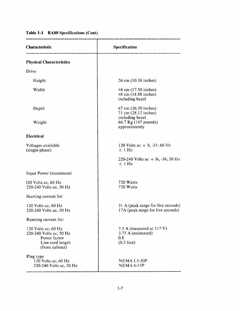
Table 1-1 RA80 Specifications (Cont)
Characteristic
Physical Characteristics
Drive
Height
Width
Depth
Weight
Electrical
Voltages available (single-phase)
Input Power (maximum)
120 Volts ac, 60 Hz 220-240 Volts ac, 50 Hz
Starting current for:
120 Volts ac, 60 Hz 220-240 Volts ac, 50 Hz
Running current for:
120 Volts ac, 60 Hz 220-240 Volts ac, 50 Hz
Power factor Line cord length (from cabinet)
Plug type 120 Volts ac, 60 Hz 220 .. 240 Volts ac, 50 Hz
26 cm (10.38 inches)
44 cm (17.50 inches) 48 cm (18.88 inches) including bezel
67 cm (26.50 inches) 71 cm(28.12 inches) including bezel 66.7 Kg (147 pounds) approximately
120 Volts ac + 8, -21; 60 Hz j: 1 Hz
220-240 Volts ac + 16, -36; 50 Hz j: 1 Hz
720 Watts 720 Watts
31 A (peak surge for five seconds) 17 A (peak surge for five seconds)
7.5 A (measured at 117 V) 3.75 A (estimated) 0.8 (8.5 feet)
NEMA L5-30P NEMA 6-15P
]-7
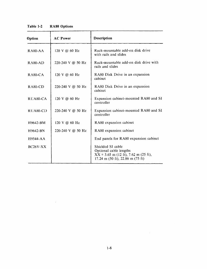
Table 1-2
Option
RA80-AA
RA80-AD
RA80-CA
RA80-CD
RUA80-CA
RUA80-CD
H9642-BM
H9642-BN
H9544-AA
BC26V-XX
RA80 Options
AC Power
120 V @ 60 Hz
220-240 V @ 50 Hz
120 V @ 60 Hz
220-240 V @ 50 Hz
120 V @ 60 Hz
220-240 V @ 50 Hz
120 V @ 60 Hz
220-240 V @ 50 Hz
Description
Rack-mountable add-on disk drive with rails and slides
Rack-mountable add-on disk drive with rails and slides
RA80 Disk Drive in an expansion cabinet
RA80 Disk Drive in an expansion cabinet
Expansion cabinet-mounted RA80 and SI controller
Expansion cabinet-mounted RA80 and SI controller
RA80 expansion cabinet
RA80 expansion cabinet
End panels for RA80 expansion cabinet
Shielded SI cable Optional cable lengths XX = 3.65 m (12 ft), 7.62 m (25 ft), 17.24 m (50 ft), 22.86 m (75 ft)
1-8
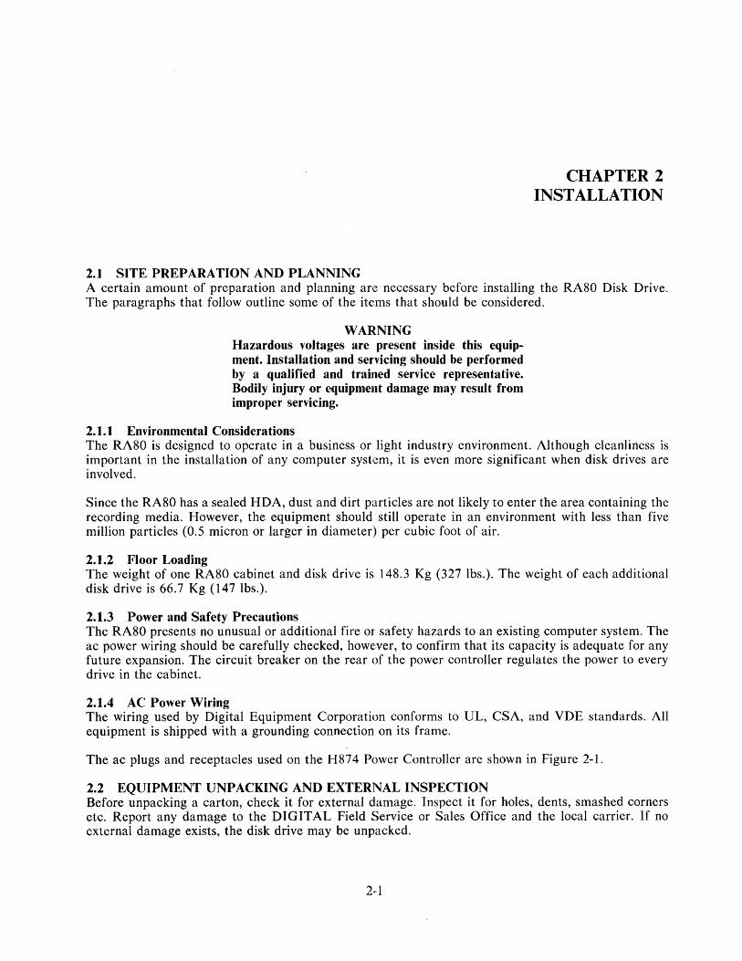
2.1 SITE PREPARATION AND PLANNING
CHAPTER 2 INSTALLATION
A certain amount of preparation and planning are necessary before installing the RA80 Disk Drive. The paragraphs that follow outline some of the items that should be considered.
WARNING Hazardous voltages are present inside this equipment. Installation and servicing should be performed by a qualified and trained service representative. Bodily injury or equipment damage may result from improper servicing.
2.1.1 Environmental Considerations The RA80 is designed to operate in a business or light industry environment. Although cleanliness is important in the installation of any computer system, it is even more significant when disk drives are involved.
Since the RA80 has a sealed HDA, dust and dirt particles are not likely to enter the area containing the recording media. However, the equipment should still operate in an environnlent with less than five million particles (0.5 micron or larger in diameter) per cubic foot of air.
2.1.2 Floor Loading The weight of one RA80 cabinet and disk drive is 148.3 Kg (327 lbs.). The weight of each additional disk drive is 66.7 Kg (147 lbs.).
2.1.3 Power and Safety Precautions The RA80 presents no unusual or additional fire or safety hazards to an existing computer system. The ac power wiring should be carefully checked, however, to confirm that its capacity is adequate for any future expansion. The circuit breaker on the rear of the power controller regulates the power to every drive in the cabinet.
2.1.4 AC Power Wiring The wiring used by Digital Equipment Corporation conforms to UL, CSA, and VDE standards. All equipment is shipped with a grounding connection on its frame.
The ac plugs and receptacles used on the H874 Power Controller are shown in Figure 2-1.
2.2 EQUIPMENT UNPACKING AND EXTERNAL INSPECTION Before unpacking a carton, check it for external damage. Inspect it for holes, dents, smashed corners etc. Report any damage to the DIGITAL Field Service or Sales Office and the local carrier. If no external damage exists, the disk drive may be unpacked.
2-·1

120 V W@
30A 1-PHASE HUBBEL
#2611 NEMA = L5-30P DEC = 12-11193
8 240 V 15 A --1-PHASE
NEMA = 6-15P DEC = 90-08853
Figure 2-1 RA80 Cabinet AC Plugs
Use the following checklist to install the RA80 Disk Drive.
• Unpacking the system (2.2.1) • Installing the leveler feet (2.2.2) • Removing internal shipping brackets
and packing material (2.2.3)
NOTE
#2610 L5-30R 12-11194
6-15R 12-11204
For add-on drive installation, see Paragraph 2.4.
2.2.1 Unpacking the System on a Shipping Pallet
6~
g o CJ
CZ-0563
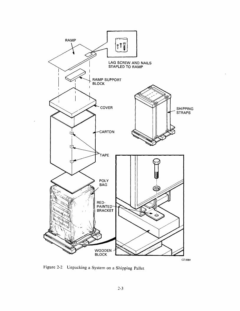
Figure 2-2 shows what a crated disk drive will look like. To unpack the disk drive and remove it from the pallet, use the following steps.
1. Remove all packaging materials. Refer to Figure 2-2.
2. Remove the four shipping bolts that secure the drive cabinet to the pallet. One is shown in the insert of Figure 2-2.
3. Construct the ramp to roll the disk drive off of the pallet. This is done by removing the plastic package enclosing the lag screw and nails from the bottom of the ramp. Use the lag screw to secure the ramp support block to the front of the shipping pallet. Then nail the ramp to the top of the ramp support block using the two nails provided. Refer to Figure 2-3.
WARNING The next step requires at least two people.
4. Remove the four wooden blocks from under the drive cabinet.
5. Carefully roll the drive cabinet down the ramp
2-2
RAMP
Figure 2-2 Unpacking a System on a Shipping Pallet
2-3
SHIPPING STRAPS
CZ-0564

PALLET
Figure 2-3 Ramp Construction
2.2.2 Installing the Leveler Feet Use the following procedure to install the leveler feet.
1. Wheel the drive cabinet to its final location before installing the feet.
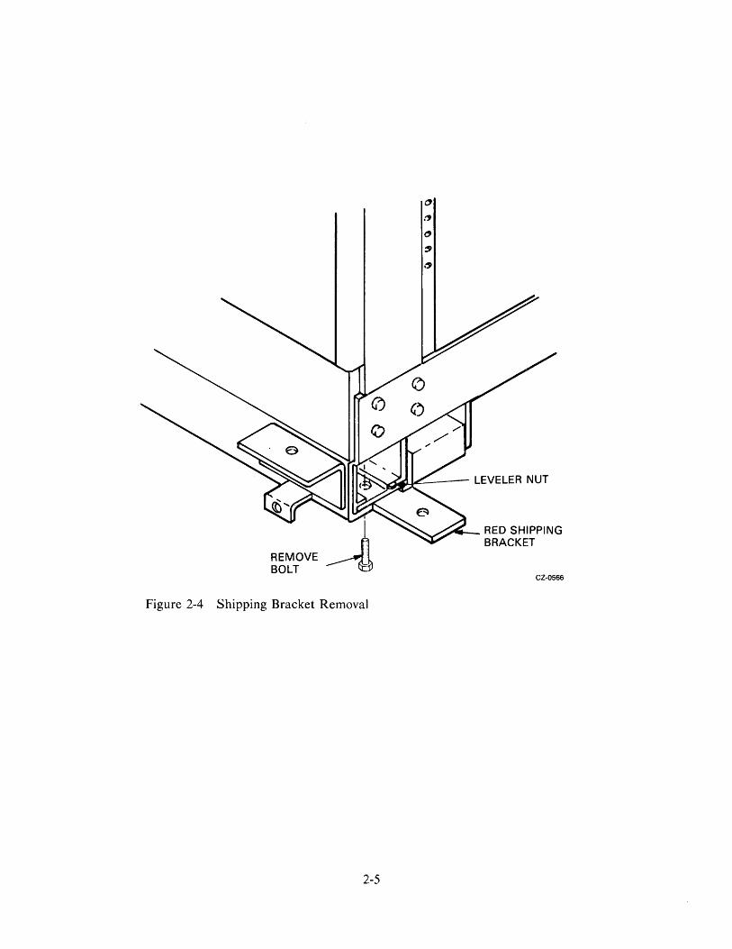
2. Unbolt and remove the four red shipping brackets and leveler nuts as shown in Figure 2-4.
3. Assemble the four leveler feet as shown in Figure 2-5. Screw the leveler foot up through the leveler nut far enough that the leveler nut may be slid back into place without raising the drive cabinet.
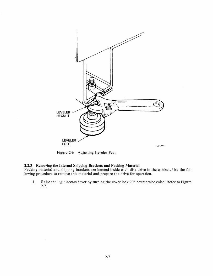
4. Slide the leveler feet into the slots in the cabinet as shown in Figure 2-6. Screw the leveler feet down until firm contact is made with the floor.
5. Adjust the leveler feet until the cabinet is level.
2-4
REMOVE BOLT
Figure 2-4 Shipping Bracket Removal
2-5
."'
CZ-0566

~ LEVELER NUT
@) FLAT WASHER
@ LOCK WASHER
~ HEX NUT
LEVE LER FOOT
~
Figure 2-5 Installation of Leveler Feet
2-6
CZ-0606
LEVELER FOOT
Figure 2-6 Adjusting Leveler Feet
2.2.3 Removing the Internal Shipping Brackets and Packing Material
CZ-0607
Packing material and shipping brackets are located inside each disk drive in the cabinet. Use the following procedure to remove this material and prepare the drive for operation.
1. Raise the logic access cover by turning the cover lock 90° counterclockwise. Refer to Figure 2-7.
2-7

LOGIC ACCESS COVER
SERVO MODULE
( FOAMPADS~~======~~~========~
Figure 2-7 Foam Pad Removal
2-8
LOGIC ACCESS COVER
/LOCK
LOGIC ACCESS COVER
PERSONALITY MODULE
CZ-0569
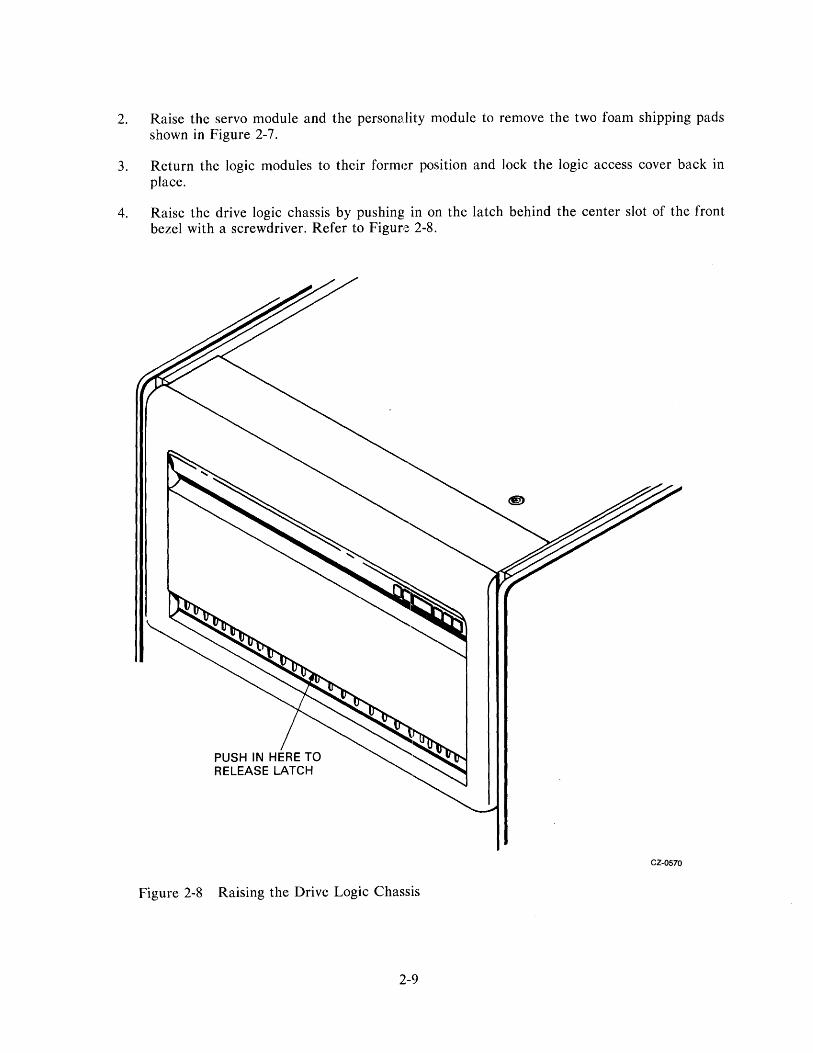
2. Raise the servo module and the personality module to remove the two foam shipping pads shown in Figure 2-7.
3. Return the logic modules to their former position and lock the logic access cover back in place.
4. Raise the drive logic chassis by pushing in on the latch behind the center slot of the front bezel with a screwdriver. Refer to Figure 2-8.
CZ·OS70
Figure 2-8 Raising the Drive Logic Chassis
2-9

5. Remove the four red shipping brackets which secure the HDA to its mountings (refer to Figure 2-9). Loosen each of the four HDA mounting nuts and remove the 5/16 inch hex-head bolts on three of the HDA mountings (refer to Figure 2-9). Then slide the shipping brackets out from under the HDA mounting nuts.
6. Remove the shipping bracket nearest the spindle motor by removing the shipping bolt and jam nuts which secure the bracket to the spindle motor assembly (refer to Figure 2-9). Slide the shipping bracket out from under the HDA mounting nut.
NOTE Save all shipping brackets and hardware for future use when moving equipment.
7. Retighten all four HDA mounting nuts.
8. Be sure that the belt tension lever is in the locked (forward) position as shown in Figure 2-10.
9. Place the positioner lock lever on the HDA into the UNLOCK position (refer to Figure 2-9).
NOTE An interlock switch (shown in Figure 2-11) prevents the spindle motor from operating while the belt tension is released. A spin-up cannot be accomplished unless the belt-tension lever is in the full forward position.
10. Lower the logic chassis until it is closed and latched.
2.3 RUA80 INSTALLATION An RUA80 disk subsystem consists of a UD.A50 disk controller and at least one RA80 Disk Drive in a cabinet. The installation procedure involves joining the disk drive cabinet to the CPU cabinet, installing the SI cables, and programming the unit address plug. Use the following checklist to check off the installation milestones.
• Join CPU and disk drive cabinets (2.3.1) • Install the SI cables (2.3.2) • Program the drive unit address plug (2.3.3) • Install add-on disk drive, if necessary (2.4)
2-10

POSITIONER LOCK LEVER
TOP VIEW
Figure 2-9 HDA Details
SPINDLE MOTOR
~~~_- SHIPPING BOLT
HDA MOUNTING FLANGE
FLAT WASHER
SHOCK MOUNT
SHIPPING BRACKET
2-11
AND JAM NUTS
5/16 HEX HEAD BOLT
FRONT VIEW CZ-OS71
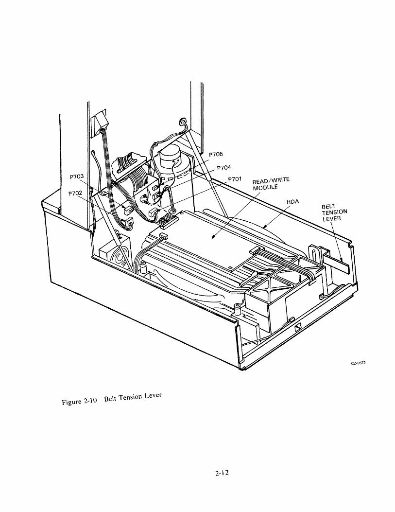
Figure 2-10 Belt Tension Lever
2-12

INTERLOCK SWITCH
2-13
CZ-OS73

2.3.1 Joining Cabinets The RA80 Disk Drive cabinet comes with a joiner panel. The joiner panel permits the drive cabinet to be joined to any cross-product CPU cabinet as shown in Figure 2-12. Use the following procedure to join the CPU and drive cabinets.
1. Open the front door of the CPU cabinet. If the CPU cabinet does not have a front door, remove the lowest front filler panel to expose the end panel lock shown in Figure 2-13.
DISK DRIVE CABINET
CPU CABINET
1111 III II !! 111111111111111111111111111 "1 HI'W'jlUlI .. "'~:'I''''''111I1II1II1 1111", .. 11111111111..1" .. : .. , .1111111 .... muu
Figure 2-12 Joining Cross-Product Cabinets
2-14
CZ-0522

FILLER PANEL BRACKET
FRONT LOCKING BRACKET
Figure 2-13 Removing Front-End Panel Lock
2-15
1I1J1II 11 /lIillllllllllllllllllllllll til HIIWII.u" .. "'"''''''!!I'!lII''''' IIlIk,llIlIIlIIlIi:I""'.",1I11111 ~I
t! 9
CPU CABINET
FRONT LEFTEND PANEL LOCK
CZ-0523

2. Remove the front left-end panel lock from the CPU cabinet.
3. Open the rear door of the CPU cabinet.
4. Loosen the screws that secure the right rear-end panel lock. Refer to Figure 2-14.
5. Remove the CPU cabinet end panel and its ground strap (if there is one).
=-=~ ::--.c
111111 111111, '1\11 11111 11111 111111
1111 11111 111111 111111 111111 11111,
'1111 11111 11111
111111 I11111
111111 111111 DRIVE CABINET I1I11I1 '11111
I11II1
111111 111111 111111 IIIII
CPU CABINET 111111 IIIII
11111
111111
I III I ~ 11 1111 ,
illll I111111 111111 11III .,,11
111111 11111
REAR LOCKING BRACKET
CZ-OS24
Figure 2-14 Removing Rear-End Panel Lock
2-16

6. Remove the two lower key buttons froD1 the left side of the CPU cabinet uprights. These buttons are removed by unscrewing the screws in their center. Refer to Figure 2-15.
TOP KEY BUTTONS
JOINER PANEL
Figure 2-15 Removing Bottom Key Buttons
LOWER KEY BUTTONS
2-17
CPU CABINETS
CZ-OS2S

7. Slide the two cabinets together and engage the top two key buttons on the CPU cabinet in the keyhole slqts on the drive cabinet joiner panel. Adjust the cabinets until their fronts are flush. Refer to Figures 2-15 and 2-16.
TOP VIEWS:
ADD-ON
CPU
ADD-ON
CPU
ADD-ON CPU
CZ-OS26
Figure 2-16 Joining the Cabinets
2-18

8. Remove the bottom front filler panel from the disk drive cabinet by removing the two screws at its base. Refer to Figure 2-17.
9. Remove the front right filler panel bracket from the disk drive cabinet.
10. Place the front locking bracket over the filler panel bracket and end panel lock as shown in Figure 2-13. Then bolt the two cabinets together with the existing hardware.
11. Open the rear door of the disk drive cabinet and loosen the screws that secure the rear leftend panel lock. Refer to Figure 2-14.
12. Slide the rear locking bracket over the end panel locks as shown in Figure 2-14. Then tighten the four screws.
13. Install the end panel that was removed from the left side of the CPU cabinet onto the left side of the drive cabinet. If an end panel is needed for drives in cross-product cabinets, order part number H9544-AA. Be sure to reattach any ground straps that might have been removed.
2.3.2 SI Cabling Procedure Both internal and external SI cables must be mounted in the I/O bulkhead assembly. The internal SI cables mount in the top of the I/0 bulkhead while the external SI cables are mounted in the bottom of the I/0 bulkhead.
2.3.2.1 Internal SI Cabling Procedure - The following procedure describes how to install the internal SI cables. Refer to Figures 2-18 and 2-19.
1. Plug the port A SI cable from the rear of the disk drive into the port A connector on the top of the I/O bulkhead. Note the orientation key.
2. Secure the port A SI cable shield terminator to the top of the I/0 bulkhead with the mounting screws provided. SI cables may have captive mounting screws on their shield terminators in the future.
3. Plug the port B SI cable from the rear of the disk drive into the port B connector on the top of the I/O bulkhead. Note the orientation key.
4. Secure the port B SI cable shield terminator to the top of the I/0 bulkhead with the mounting screws provided.
:2.3.2.2 External SI Cabling Procedure - The external SI cables must be installed between the CPU cabinet, I/O bulkhead connector, and the drive cabinet I/O bulkhead connector. The CPU I/O bulkhead connector should already be installed. If this is not the case, refer to the disk controller user guide and follow the installation procedure. When the CPU cabinet I/O bulkhead connector has been installed, follow the instructions in the disk controller user guide to install the SI cables at the CPU cabinet end. The following procedure describes how to install the SI cables at the drive cabinet end.
1. Plug the external SI cable into port A of the SI bulkhead shown in Figure 2-18. External SI cables should enter from the bottom.
2. Install the two screws that hold the SI cable shield terminator in place and tighten them securely. Refer to Figure 2-18.
2-19
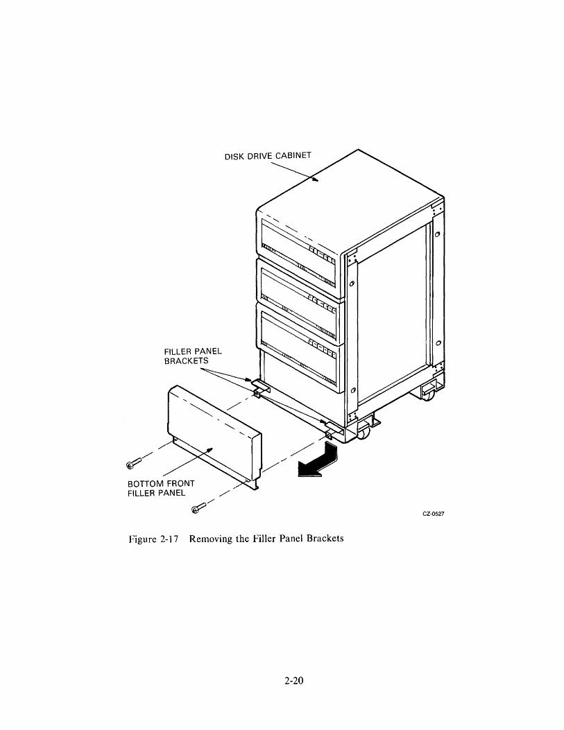
Figure 2-17 Removing the Filler Panel Brackets
2-20

INTERNAL SI CABLES
EXTERNAL SI CABLE FO R PO RT A ..-----
Figure 2-18 SI Cable Shield Terminator Installation
2-21
CABLE ENTRY RETAINER
MOUNTING SCREWS
CZ-OS74

I 10 8 · Q
@) ~
CABLE CLAMP HOLE NO. 56
CABLE CLAMP HOLE NO. 14
DRIVE SEQUENCE BULKHEAD
o o SI CABLE
~ ______ ~====~---------11~~H~~~~~_~~~I/OBULKHEAD
CABLE ENTRY RETAINER
Figure 2-19 Single Drive External SI Cables
2-22
CZ-0575
3. If more than one disk drive is in the cabinet, additional SI cables must be installed. Refer to the RA80 add-on installation procedure (paragraph 2.4) for instructions.
4. Clamp the external SI cables to the cable entry retainers below the I/O bulkheads with either a hose clamp or tie-wrap.
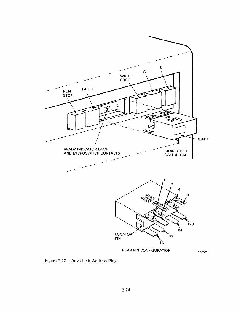
2.3.3 Programming the Drive Unit Address Plug The READY switch cap on the operator control panel serves as the drive unit address plug. A drive unit number between 0 and 251 must be programmed into the unit address plug. To select a drive unit number, remove the READY switch cap and cut off the tabs that add up to the selected number. (Figure 2-20 shows the binary value of each tab.) For example, if address 7 is selected, tabs 1, 2, and 4 would be cut off. Leave all of the tabs on if the unit number 0 is desired. After the drive unit number has been selected, paste the chosen number gum label in the recessed rectangle on the READY switch cap.
2.4 RA80 ADD-ON INSTALLATION The RA80 disk subsystem comes with only one RA80 disk drive in its basic configuration. The maximum configuration allows up to four RA80 disk drives. Use the following installation procedures for RA80 add-ons. A checklist is provided here to check off each installation step accomplished.
• Remove the front filler panel (2.4.1)
• Install the chassis slide assembly (2.4.2)
• Mount the RA80 on the slides (2.4.3)
• Remove the internal shipping brackets and packing material (2.4.4)
• Program the drive unit address plug (2.4.5)
• Secure the electrostatic discharge bracket (2.4.6)
• Install the SI cables (2.4.7)
• Mount the I/O bulkhead (2.4.8)
• Install the drive sequence cables (2.4.9)
• Plug in the AC cord (2.4.10)
• Route and clamp the cables (2.4.11)
2.4.1 Remove the Front Filler Panel The first add-on drive is placed in the middle bay of the RA80 cabinet. The second add-on drive goes in the bottom bay. Remove the filler panel for the correct location. The filler panel is removed by unscrewing the four 10-32 hex nuts that hold it to the cabinet frame. Access to these hex nuts is through the rear of the cabinet. Refer to Figure 2-21.
2-23
B
--
READY INDICATOR LAMP AND MICROSWITCH CONTACTS --
~~-CODED SWITCH CAP
---------------
16
REAR PIN CONFIGURATION
Figure 2-20 Drive Unit Address Plug
2-24
CZ-0576

HEX NUT 10-32 (4 PL)
FILLER , /~ PANEL • " , ......
• If)
• If)
• (JI
If) e ~ • " •
e t\
• e • • • • • • • • • • e
• • • .. • • • • •
CZ-OS77
Figure 2-21 Removing Cabinet Filler Panels
2-25

2.4.2 Install the Slide Assembly Each RA80 add-on disk drive has to be mounted into the drive cabinet on a slide assembly. Use the following procedure to install the slides into the drive cabinet.
1. Locate the left and right chassis slides and screw a chassis slide bracket onto each end. Two 8-32 X 0.31 inch Phillips head sem screws are used to mount each chassis slide bracket. Refer to Figure 2-22. Sem are screws with star washers attached.
NOTE 1. REPEAT FOR LEFT CHASSIS SLIDE.
Figure 2-22 Chassis Slide Bracket Installation
2. Gather together the following hardware.
• 4 Philli ps head screws - 10-32 X 5/8 inch
CHASSIS SLIDE BRACKETS
• 4 lock washers - 0.380 inch 0.0. X 0.200 inch to.
• 2 slide mount spacers (2 holes)
• 4 Phillips head sem screws - 10-32 X 1/2 inch
• 4 nut bars (4 holes)
2-26
CZ-0578

3. Mount the chassis slides to the front vertical upright as shown in Figure 2-23. If this is a first add-on drive (middle bay), use mounting holes 27 and 31, counting from the bottom. If this is a second add-on drive (bottom bay), use nlounting holes 9 and 13, counting from the bottom. Notice that this installation to the front vertical upright requires both a slide mount spacer and a nut bar.
VIEWED FROM FRONT OF CABINET
CABINET FRONT LEFT UPRIGHT
LOCK ,~
WASHERS~~~/
" < PHILLIPS HEAD SCREWS 10-32 X 5/8"
NOTE
SLIDE MOUNT SPACER
1. REPEAT FOR FRONT RIGHT UPRIGHT.
Figure 2-23 Mounting Chassis Slide to Front Upright
2·,27
NUT BAR
CHASSIS SLIDE BRACKET
CZ-0579

4. Mount the chassis slides to the rear vertical uprights as shown in Figure 2-24. Note that only a nut bar is used here with sem screws. Use the same vertical upright mounting holes specified in Step 3.
VIEWED FROM FRONT OF CABINET PHILLIPS HEAD SEM SCREWS 10-32 X 1/2"
NOTE
NUT BAR
CHASSIS SLIDE BRACKET
LEFT REAR VERTICAL UPRIGHT
1. REPEAT FOR RIGHT REAR VERTICAL UPRIGHT.
Figure 2-24 Mounting Chassis Slide to Rear Upright
2-28
CZ-OS80

5. Mount the electrostatic discharge bracket on the rear left vertical upright. It will mount over the chassis slide bracket. The two sem screws will pass through the two center holes of the chassis slide bracket and be held by the nut bar inside. Refer to Figure 2-25. If this is a first add-on drive (middle bay), use mounting holes 28 and 30. If this is a second add-on drive (bottom bay), use mounting holes 10 and 12.
VIEWED FROM REAR OF CABINET
LEFT VERTICAL UPRIGHT VIEWED FROM REAR
ELECTROSTATIC DISCHARGE BRACKET
...... ...... .....
",~ /'"'W
PHILLIPS HEAD SEM SCREWS 10-32 X 1/2"
CZ-0581
Figure 2-25 Mounting the Electrostatic Discharge Bracket
2-29

6. Insert the two cable retainer springs into the rear of the left and right chassis slides as shown in Figure 2-26. Push the cable retainer springs in until they latch into place and cannot be removed.
7. Mount an 11/16 inch cable clamp onto each cable retainer spring as shown in Figure 2-26. Each cable clamp should be mounted on the side of the cable retainer spring that is away from the outside of the cabinet.
VIEWED FROM FRONT OF CABINET
NOTE
PHILLIPS HEAD SEM SCREW 10-32 X 1/2"
CABINET SLIDE MEMBER
INTERMEDIATE SLIDE MEMBER
~~
1. REPEAT FOR CHASSIS SLIDE ON RIGHT SIDE.
Figure 2-26 Installation of Cable Retainer Springs
2-30
......
CABLE RETAINER SPRING
SPACER
/ CABLE CLAMP ~_ 11/161NCH
" ~ /~'~
FLAT WASHER / 0.500 00 X 0.281 10
PHILLIPS HEAD SCREW 10-32 X 5/8"
CZ-0582

8. Install the drive detent latch onto the left side vertical upright (when viewed from the rear of the cabinet as shown in Figure 2-27). Tighten the screws just enough so that the drive detent latch will not move freely, but can be later adjusted when the drive is pushed in. If this is a first add-on drive (middle bay), use mounting holes 36 and 37. If this is a second add-on drive (bottom bay), use mounting holes 18 and 19.
VIEWED FROM FRONT OF CABINET
PHILLIPS HEAD SEM SCREWS 10-32 X 1/2"
4 ..... ....... ..... ....... ......... .........
....... ....... ....... .....
CABINET REAR .LEFT VERTICAL UPRIGHT
Figure 2-27 Installation of Drive Detent Latch
2-31
DRIVE DETENT LATCH
CZ-0583
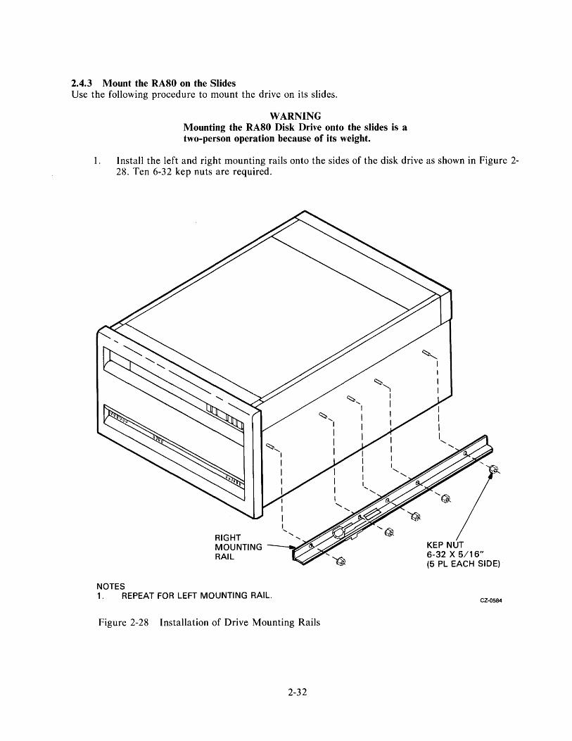
2.4.3 Mount the RA80 on the Slides Use the following procedure to mount the drive on its slides.
WARNING Mounting the RA80 Disk Drive onto the slides is a two-person operation because of its weight.
1. Install the left and right mounting rails onto the sides of the disk drive as shown in Figure 2-28. Ten 6-32 kep nuts are required.
RIGHT MOUNTING ~_ .. .J"/
RAIL
NOTES 1. REPEAT FOR LEFT MOUNTING RAIL.
Figure 2-28 Installation of Drive Mounting Rails
2-32
~"l I I I I
~ I
KEP NUT 6-32 X 5/16" (5 PL EACH SIDE)
CZ-0584

2. Remove the drive power supply using th,~ following procedure.
a. Raise the drive logic chassis. Refer to Figure 2-8.
b. Unplug P701, P702, P703, P704, and P705 from the drive power supply. Refer to Figure 2-29.
c. Remove the ground wire from the top ground terminal on the front of the power supply. Refer to Figure 2-29.
Figure 2-29 Removal of Power Supply Connections
2-33

d. Remove the six hex-head slotted screws and washers that hold the power supply in place. Set the hardware aside for re-installation. Refer to Figure 2-30.
e. Pull the power supply out of the rear of the drive while guiding the molded plug through the chassis cutout.
3. Extend the stabilizer foot forward, as shown in Figure 2-31.
CZ-0087
Figure 2-30 Removal of Drive Power Supply
2-34

co
STABILIZER FOOT
CZ-0608
Figure 2-31 Extending Cabinet Stabilizer Foot
2-35

4. Extend each chassis slide all the way forward until it locks, as shown in Figure 2-32.
5. Pick up the drive (using two persons) and place it on top of the chassis slides, as shown in Figure 2-32. Push the drive towards the rear of the slides until its mounting rails hit the stop.
6. Secure the drive to the chassis slides using four 8-32 X 0.31 inch Phillips head sem screws, as shown in Figure 2-32.
7. Push the drive into the cabinet by releasing lock arms B and then lock arms A, as shown in Figure 2-32.
8. Re-install the power supply in the drive through the rear. Slide the drive forward again to reconnect the internal power supply connectors and the ground wire.
9. Adjust the drive detent latch so that it prevents the drive from sliding forward and then tighten the drive detent latch screws.
DRIVE CABINET
SLIDE ASSEMBLY
PHILLIPS HEAD SEM SCREWS 8-32 X 0.31 (2 EACH SIDE)
Figure 2-32 Extending the Chassis Slides
2-36
RA80 DISK DRIVE
CZ-0600

2.4.4 Remove the Internal Shipping Brackets and Packing Material Remove the internal shipping brackets and packing material from inside the drive using the procedure already described in Paragraph 2.2.3.
2.4.5 Program the Drive Unit Address Plug Program the drive unit address plug according to the instructions already provided in Paragraph 2.3.3.
2.4.6 Secure the Electrostatic Discharge Bracket The electrostatic discharge bracket is intended to ground the disk drive to the cabinet whenever the drive is operating. To complete this ground path, the bottom left drive power supply screw should be removed and screwed back in through the electrostatic discharge bracket as shown in Figure 2-33. This ground connection must always be made whenever the drive is operating.
To slide the drive forward, remove the power supply, screw in the electrostatic discharge bracket, and push on the drive detent latch. Remember to reconnect the electrostatic discharge bracket each time the drive is pushed back in the cabinet.
ELECTROSTATIC DISCHARGE BRACKET
NOTE
LEFT REAR OF DISK DRIVE
1. REMOVE POWER SUPPLY SCREW TO SLIDE DRIVE FORWARD. REPLACE SCREW THROUGH BRACKET EACH TIME THE DRIVE IS SLID BACK IN CABINET. CZ-0586
Figure 2-33 Securing the Electrostatic Discharge Bracket
2-37

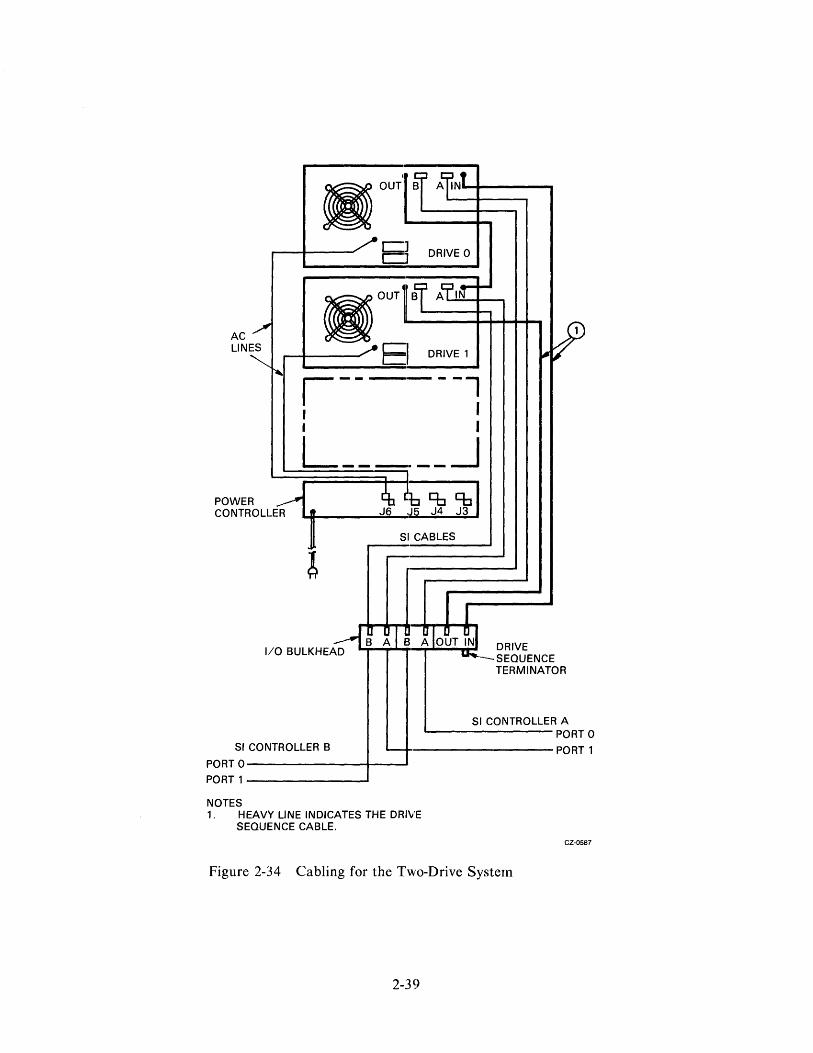
2.4.7 Install the SI Cables The two internal SI cables that exit from the rear of the add-on drive must be connected to the top of the I/O bulkhead assembly. The external SI cable that connects the drive cabinet to the disk controller must be mounted on the bottom of the I/O bulkhead assembly. If two disk controllers are used for dualport operation, a second external SI cable must be installed. The SI cables are connected to the I/O bulkhead before its installation onto the drive cabinet. Field Service engineers can hold the I/O bulkhead in their hands and install the SI cables with more ease. Figures 2-34 and 2-35 show the electrical wiring diagrams for add-on disk drives. Use the following procedure to install the SI cables.
1. Locate the port A SI cable where it exits the rear of the disk drive. Follow the cable down to its end and plug the connector into port A on top of the I/O bulkhead assembly. Note the orientation key.
2. Screw the port A SI cable shield terminator into the I/O bulkhead assembly. Early versions of the disk drive will need separate screws to mount the shield terminator. Future versions will have captive hardware so the screws will not be lost. Refer to Figure 2-36.
3. Repeat Steps 1 and 2 for the port B SI cable.
4. Plug the SI cable from the first disk controller into the port A connector on the bottom of the I/O bulkhead assembly. Note the orientation key.
5. Screw the shield terminator of this cable into the I/O bulkhead assembly as in Step 2.
6. If a second disk controller is used, mount its SI cable into port B on the I/O bulkhead assembly.
2-38
AC / LINES
~"
POWER CONTROLLER
C1 C1 DRIVE 0
I------l I I I I L _____ -.J
SI CABLES
L
1/0 BULKHEAD DRIVE SEQUENCE TERMINATOR
SI CONTROLLER A PORT 0
SI CONTROLLER B ~+-----------------PORT
PORT 0--------------+---PORT1------------~
NOTES 1. HEAVY LINE INDICATES THE DRIVE
SEQUENCE CABLE.
Figure 2-34 Cabling for the Two-Drive Systern
2-39
CZ-OS87
f AC LINE
... "'"
WER
"" I --I PO
CO NTROLLER I ~
n
~ !
BOUT BI Al' IN
I I DRIVE 0
BOUT BI A'T ~ ~
c:::J DRIVE 1 CJ
BOUT ~ Al'1~ ~
15 DRIVE 2
~ I 'It
~ .. ~~ ~
SI CABLES
BOUT1~ AIM
,)JJ I I DRIVE 3
r-- --, ~
I I I
I I
__ J AC I
LI\ I . --r-- ---1 I I I
L __ I
__ -.1 JD
~ t:b 'b Cb \ J6 J5 J4 J3
POWER CONTROLLER
! SI CABLES
1/0 I I ~ BULKHEAD
D D f.i'@ lR I I A OUT IN 1/0 BULKHEAD
0 DI D DID 01 D C B A B A B A OUT IN DRIVE SEQUENCE I u- - TERMINATOR
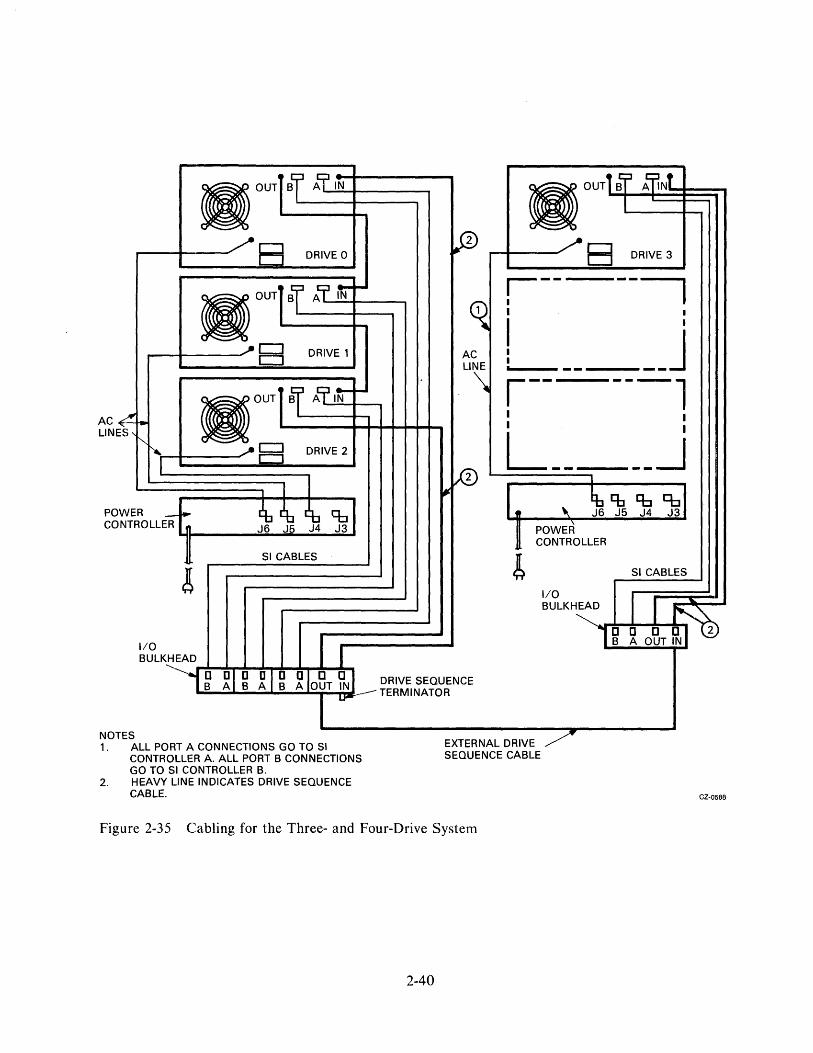
NOT ES 1. ALL PORT A CONNECTIONS GO TO SI
CONTROLLER A. ALL PORT B CONNECTIONS GO TO SI CONTROLLER B.
2. HEAVY LINE INDICATES DRIVE SEQUENCE CABLE.
EXTERNAL DRIVE / SEQUENCE CABLE
Figure 2-35 Cabling for the Three- and Four-Drive System
2-40
CZ-0588

NOTES
u MOUNT,NGL: SCREWS I
MOUNTING SCREWS
1. LATER VERSIONS OF SHIELD TERMINATORS WILL HAVE CAPTIVE MOUNTING SCREWS.
INTERNAL SI CABLE
SHIELD --TERMINATOR
ORIENTATION KEY
1/0 BULKHEAD ASSEMBLY
SHIELD TERMINATOR
EXTERNAL SI CABLE
CZ-0589
Figure 2-36 Mounting SI Cable Shield Terminators
2-41

2.4.8 Mount the I/O Bulkhead The I/0 bulkhead assembly must be installed on the rear base of the drive cabinet for each add-on disk drive. Screw the I/0 bulkhead assembly onto the rear of the cabinet as shown in Figure 2-37. For the first add-on drive, mount the I/O bulkhead assembly in the drive 1 location. For a second add-on drive, mount the I/O bulkhead assembly in the drive 2 location.
DRIVE SEQUENCE CABLE BULKHEAD
1/0 BULKHEAD FOR FIRST ADD-ON
1/0 BULKHEAD FOR SECOND ADD-ON
CZ-0590
Figure 2-37 Mounting the I/O Bulkhead Assembly
2-42

2.4.9 Install the Drive Sequence Cables Figures 2-34 and 2-35 show the electrical wiring diagrams for add-on disk drives and should be used as a reference when installing drive sequence cables. Use the following procedures to install these cables.
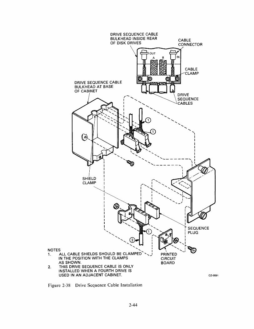
1. Unplug the drive sequence cable from the output connector on drive 0 (top drive). This is accomplished by raising the rear cover and removing the drive sequence cable from its cable clamp. Refer to Figure 2-38.
2. Plug the drive sequence cable, which was removed from the output connector of drive 0, into the output connector on drive 1 (for one add-on), or into the output connector of drive 2 (for two add-ons).
3. Install the new 8 foot drive sequence cable between the output connector of drive 0 and the input connector on drive 1. If a second add-on drive is installed, install another 8 foot drive sequence cable between the output connector of drive 1 and the input connector of drive 2.
4. Tie-wrap the drive sequence cable to the existing SI cable clamps.
5. Add a drive sequence cable between the drive sequence bulkheads on each drive cabinet whenever a second cabinet is used. Refer to Figure 2-35 and 2-38.
:2.4.10 Plug in the AC Power Cord The ac power cord on each add-on disk drive must be plugged into the ac receptacle on the power controller at the base of the cabinet. Refer to Figure 2-39.
2.4.11 Route and Clamp the Cables The cables from the add-on drives must now be routed and clamped properly to allow the drive to slide out of the cabinet. Use the following procedures to route and clamp the cables.
1. Mount the spacers and cable clamps into the rear vertical uprights as shown in Figure 2-40. If this is the first add-on drive (middle bay), mount the cable clamps in mounting holes 44 of the left and right vertical uprights. If this is the second add-on drive (bottom bay), mount the cable clamps in mounting holes 23 of the left and right vertical uprights.
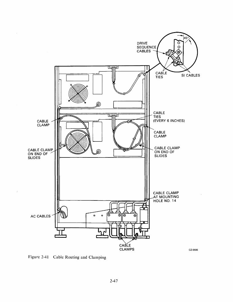
2. Use the 15 cable ties provided with each add-on drive to route and tie the cables approximately where shown in Figure 2-41. Three cable ties are used on the ac power cord, and seven cable ties are used on the SI and drive sequence cables.
3. The cables should be tie-wrapped to the clamp previously mounted on the rear of the chassis slides.
4. Form a service loop in the cables approximately 8 inches in diameter, as shown in Figure 2-40. Clamp the output of the service loop with the cable clamps just installed on the vertical uprights.
5. Tie-wrap the cables at the bottom of the cabinet to the cable clamp at mounting hole 14.
2-43
DRIVE SEQUENCE CABLE BULKHEAD INSIDE REAR OF DISK DRIVES
DRIVE SEQUENCE CABLE BULKHEAD AT BASE OF CABINET
SHIELD CLAMP
I I I I I I I I I
CABLE CONNECTOR
CABLE CLAMP
L " SEQUENCE
"--"" r"~~"'! PLUG ....... I ~ I
" I \:?",I ....... I 'I'" "I 'I~
NOTES ',I' .......... J ll!I 1. ALL CABLE SHIELDS SHOULD BE CLAMPED ' ........ J PRINTED
IN THE POSITION WITH THE CLAMPS CIRCUIT AS SHOWN. BOARD
2. THIS DRIVE SEQUENCE CABLE IS ONLY INSTALLED WHEN A FOURTH DRIVE IS USED IN AN ADJACENT CABINET. CZ·0591
Figure 2-38 Drive Sequence Cable Installation
2-44

J6
AC PLUG DRIVE 1
Figure 2-39 Power Controller AC Receptacles
2-45
AC CORDS
CZ-0593

KEP NUT 10-32 X 3/8"
STANDOFF 10-32, 6-32
FLAT WASHER 0.375 OD X 0.156 ID
PHILLIPS HEAD SCREW 6-32 X 5/16"
Figure 2-40 Mounting Cable Clamps on Uprights
2-46
CABLE CLAMP 3/8"
CZ-0594
CABLE CLAMP
CABLE CLAMP ON END OF SLIDES
AC CABLES
Figure 2-41 Cable Routing and Clamping
2-47
CABLE CLAMPS
CABLE TIES (EVERY 6 INCHES)
CABLE CLAMP
CABLE CLAMP ON END OF SLIDES
CABLE CLAMP AT MOUNTING HOLE NO. 14
CZ-0595
2.5 RUA80 CHECKOUT PROCEDURE Use the following RA80 checkout procedure for checking out each RA80 Disk Drive after installation.
2.5.1 Applying Power
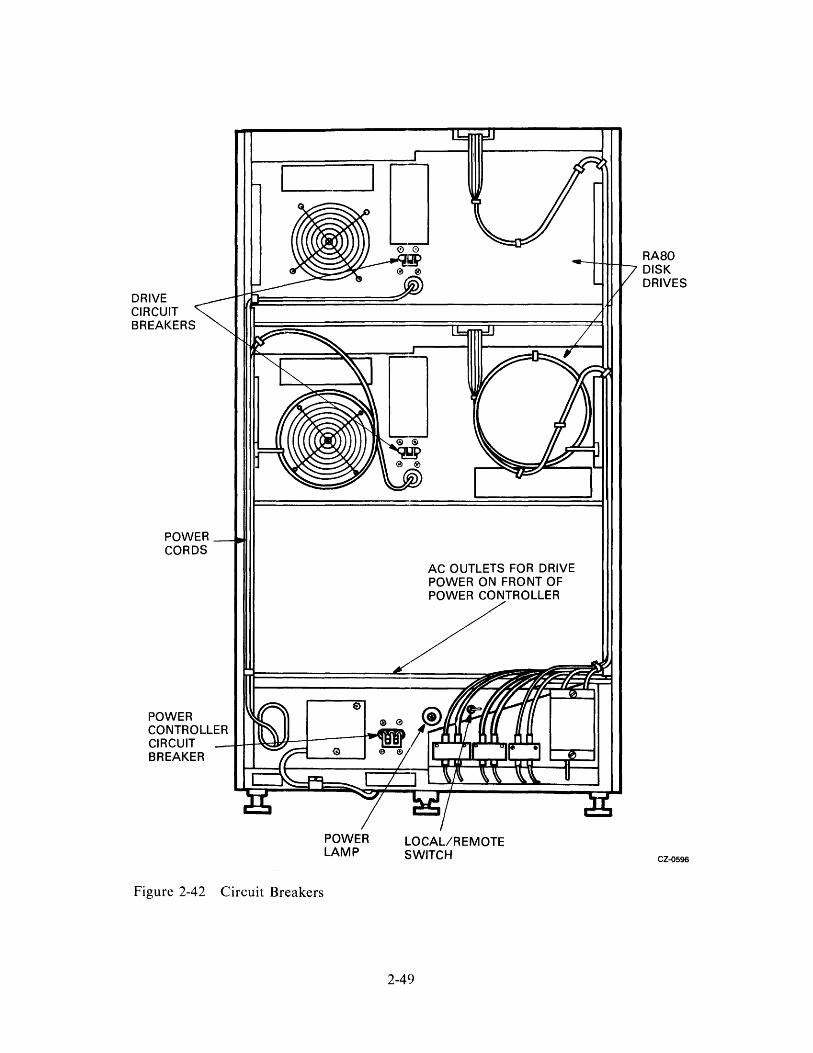
I. Verify that the ac circuit breaker on the power control unit is off. Also verify that the circuit breaker on each disk drive is off. (Refer to Figure 2-42.)
2. If this is an add-on drive, plug the RA80 power cord into the ac power outlet on the power control unit at the bottom of the cabinet.
3. Check that the LOCAL/REMOTE switch on the power controller is in the LOCAL position.
4. Plug the ac power cord from the power control unit into an ac receptacle.
5. Switch on the ac circuit breakers on the power control unit. The circuit breaker on each drive is switched on during the drive checkout procedure that follows.
2.5.2 Drive Checkout Procedure The following procedure is used to check out each RA80 Disk Drive. The HDA should be received preformatted from the factory. Both customer data areas and maintenance cylinders are formatted. Replacement HDA format information is available in the RA80 Disk Drive Service Manual, Section 5.2.
NOTE This checkout procedure should be used only by trained maintenance personnel.
1. Switch on the ac circuit breaker at the rear of the drive. Refer to Figure 2-42. The front panel lights will go off if the drive hardcore diagnostics successfully complete.
2. Open the logic access cover and raise the servo and personality modules to expose the maintenance controls on the microprocessor module. Figure 2-43 shows the location of the LED display, the ENTER/RESET switch, and the rotary switches. Using these controls, perform the drive diagnostic tests listed in Table 2-1.
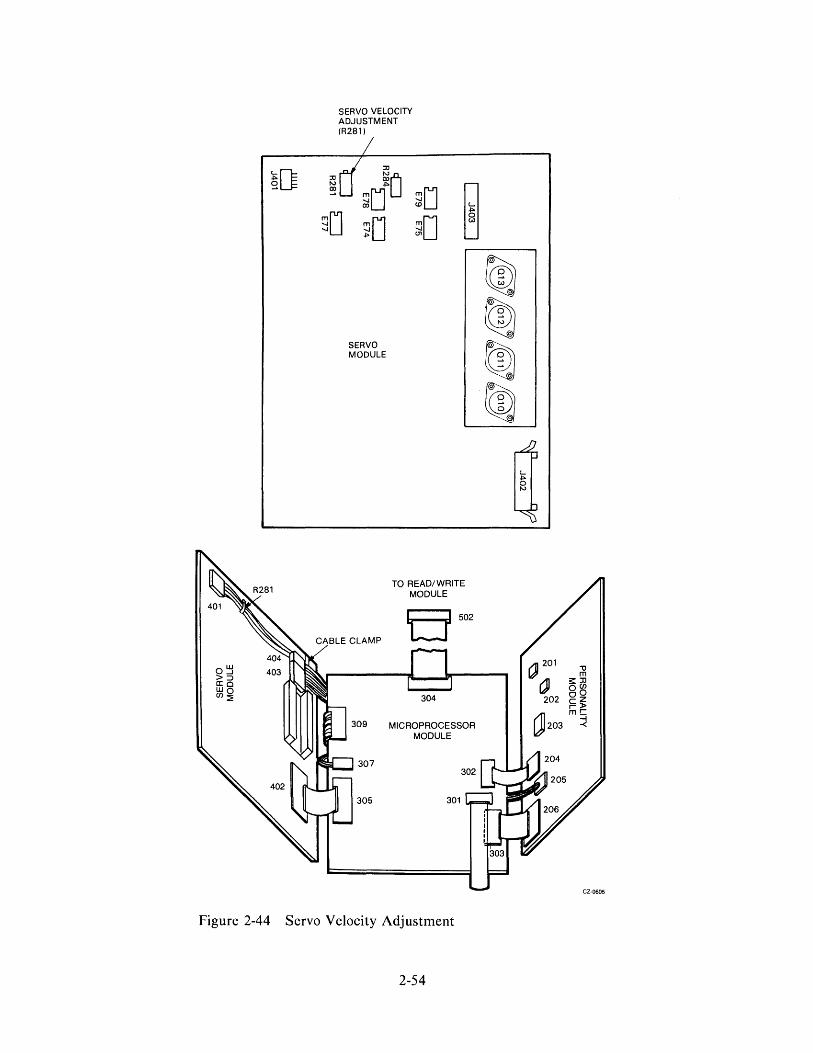
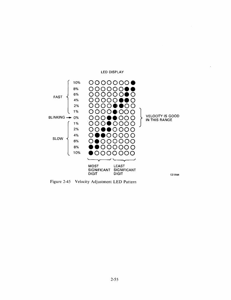
The servo velocity test in Table 2-1 requires the adjustment of potentiometer R281 on the servo module. Figure 2-44 shows the location of R281. Figure 2-45 shows the patterns seen in LED display on the microprocessor module as the servo velocity adjustment is made.
NOTE If anyone of these drive-resident diagnostic tests described in Table 2-1 fails, refer to the RA80 Disk Drive Service Manual or the RA80 Disk Drive Maintenance Guide for further troubleshooting procedures.
2.5.3 Disk Subsystem Checkout Procedure Refer to the installation chapter in the appropriate controller user guide.
2-48
DRIVE CIRCUIT BREAKERS
POWER CORDS
POWER
RA80 ----t-H-I--L_ DIS K
AC OUTLETS FOR DRIVE POWER ON FRONT OF
~TROLLER
DRIVES
CONTROLLER" lWU'l»-+--i'~~ CIRCUIT -BREAKER
Figure 2-42 Circuit Breakers
POWER LAMP
LOCAL/REMOTE SWITCH
2-49
CZ-0596
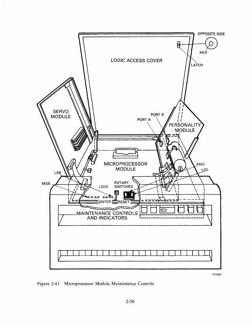
LOGIC ACCESS COVER
"-__ MAl NTE N AN C E CO NTR 0 LS .l.!=:....::=-.!::::::==-~--==-.:~~ AND INDICATORS
CZ-0597
Figure 2-43 Microprocessor Module Maintenance Controls
2-50

Table 2-1 Drive-Resident Diagnostic Tests
Rotary *LED Switch Action Response
1. Go Off-Line FF a. Set FF, push ENTER Blinking FF ••••••••
b. Push ENTER Steady FF • ••••••• 00 c. Set 00, push ENTER Steady 00 00000000
d. Push ENTER Blinking EC ··.0··00
2. Logic Test 22 a. Set 22, push ENTER Momentary 22 00.000.0
Steady AA ·0.0·0.0
b. Push ENTER Blinking EC • •• 0 •• 00
3. Operator Control Panel Test 00 a. Set 00, push ENTER Momentary 00 0000··0.
Steady E7 ···00 ••• b. Push RUN Steady 00 00000000
c. Push WRITE PROTect Steady 01 0000000.
d. Push port A switch Steady 02 000000·0
e. Push port B switch Steady 04 00000·00
NOTE Front panel indicator should light as each switch is pushed.
f. Remove unit plug; READY indicator should go out
g. Replace unit plug; READY indicator should light
h. Push ENTER LSB of ser. no. i. Push ENTER 2nd byte of ser. no. j. Push ENTER 3rd byte of ser. no. k. Push ENTER Unit plug no. 1. Push ENTER Steady AA .0·0·0.0
m. Push ENTER Blinking EC ··.0··00
4. Static Servo Test 27 a. Set 27, push ENTER Momentary 27 00·00 •••
Steady AA ·0.0·0.0
b. Push ENTER Blinking EC • •• 0 •• 00
* A • equals ON and a 0 equals OFF. If anyth:ing other than the given response occurs, refer to the maintenance guide or call your field service representative.
2-51

Table 2-1 Drive-Resident Diagnostic Tests (Cont)
Rotary *LED Switch Action Response
5. Spindle Control Utility IE a. Set I E, push ENTER Momentary IE 000····0
Steady E7 • •• 00· •• b. Push RUN to start
spin-up; spin-up complete indicated by AA Steady AA ·0.0·0·0
c. Push ENTER Blinking EC • •• 0.·00
6. Servo Velocity Test 26 a. Set 26, push ENTER Momentary 26 00.00··0
Momentary E7 • •• 00· •• % Speed deviation
b. Let test run for 20 minutes for temper-ature stability
c. Monitor LED display; Slowly adjust R28I on servo module until the velocity is ± 1 % (refer to Figures 2-29 and 2-30)
DO d. Set DO, push ENTER Steady AA or ·0.0·0·0 blinking EC • •• 0··00
e. I f solid AA is dis-played, push ENTER to return to EC prompt
7. Loop Mode Utility CF a. Set CF, push ENTER Momentary CF ·.00·· ••
Blinking 01 0000000.
4F b. Set 4F, push ENTER Momentary 4 F 0.00·· ••
Steady AA ·0·0.0.0
c. Push ENTER Blinking EC • •• 0··00
8. Entire Unit Test 25 a. Set 25, push ENTER Momentary 25 00·00·0.
Steady E7 • •• 00· •• b. Let run for 10 min.
DO c. Set DO, push ENTER Steady AA or ·0.0.0·0
blinking EC • •• 0··00 d. If solid AA is dis-
played, push ENTER to return to EC prompt
2-52
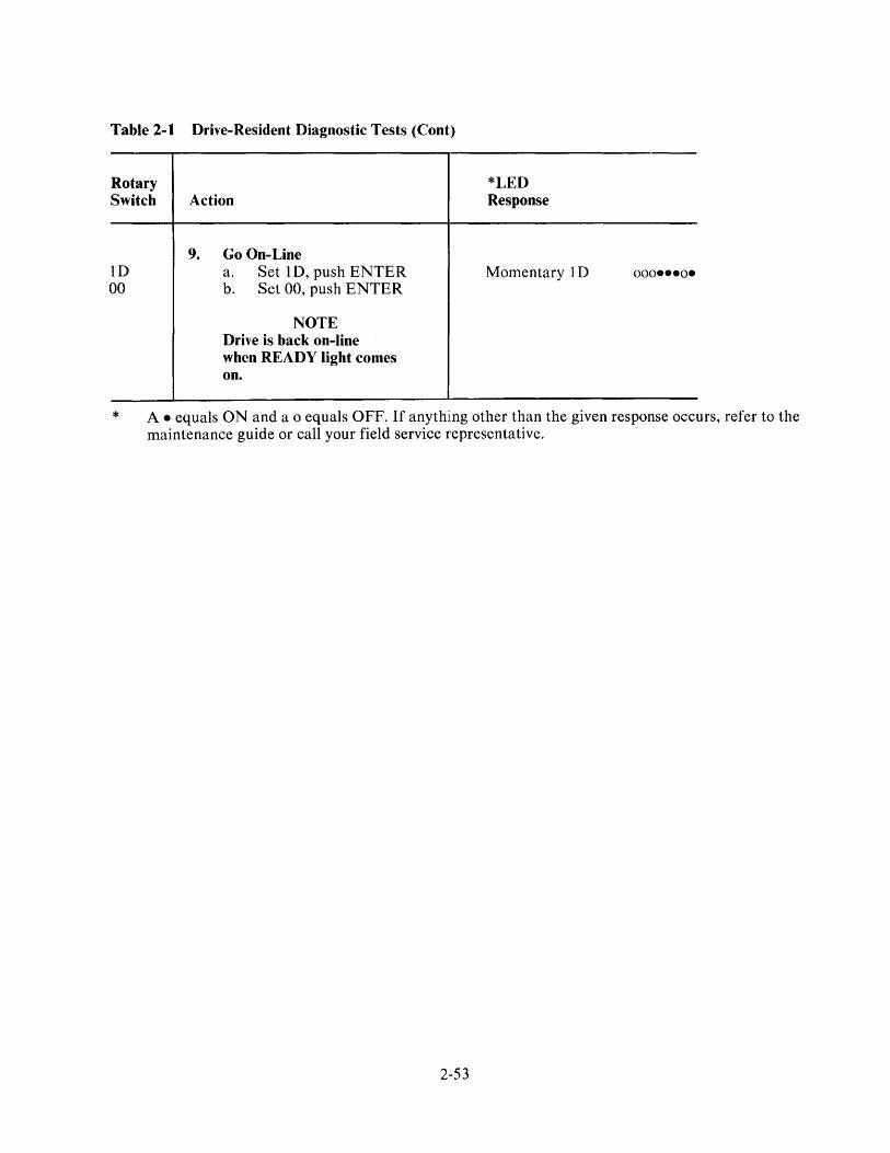
Table 2-1 Drive-Resident Diagnostic Tests (Cont)
Rotary Switch
ID 00
Action
9. Go On-Line a. Set 1 D, push ENTER b. Set 00, push ENTER
NOTE Drive is back on-line when READY light comes on.
*LED Response
Momentary 1 D 000---0-
* A - equals ON and a 0 equals OFF. If anythilng other than the given response occurs, refer to the maintenance guide or call your field service representative.
2-53
O~ >:::) a:: 0 wO en:;
SERVO VELOCITY ADJUSTMENT (R281)
SERVO MODULE
307
305
TO READ/WRITE MODULE
0 502
304
MICROPROCESSOR MODULE
301
Figure 2-44 Servo Velocity Adjustment
2-54
i:;Y 201 "'0 m
~ :!!::D Oen 0 0
202 C Z r»
~203 me ~
LED DISPLAY
10% OOOOC)OOe 8% ooooooee
FAST 6% ooooooeo 4% OOOOC)eeO 2% ooooeeoo 1% 0000_000 } BLINKING --... 0% oooeeooo VELOCITY IS GOOD
IN THIS RANGE 1% oooec)ooo 2% ooeeoooo 4% o_eooooo
SLOW 6% oeoooooo 8% eeoooooo 10% eooooooo
'----y-----I '-~
MOST LEAST SIGNIFICANT SIIGNIFICANT DIGIT DIGIT CZ-0598
Figure 2-45 Velocity Adjustment LED Pattern
2-55

3.1 OPERATOR CONTROLS AND INDICATORS
CHAPTER 3 OPERATING INSTRUCTIONS
Operating controls for the RA80 are located on the front and rear panels of the disk unit.
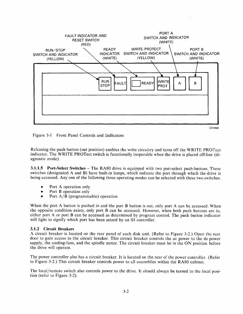
3.1.1 Front Panel Controls and Indicators The paragraphs that follow (3.1.1.1 through 3.1.1.5) describe the function of each control and indicator located on the front panel of the disk unit (Figure ).-1). The front panel controls will not function when the drive is placed off-line (in the diagnostic mode), unless the diagnostic test calls for the use of that ]particular control.
3.1.1.1 RUN/STOP Switch and Indicator (A Two-Position Push Button with Built-In Indicator Lamp)In the RUN position (button pushed in), the switch indicator lights up and a spin-up sequence begins iif all power has been turned on and no faults are detected. An automatic spin-up attempt will be made following power interruptions as long as the switch relnains in this position.
NOTE A three-minute delay is re,commended between each stop and restart to prevent opening the thermal circuit breaker associated witth the spindle motor.
In the STOP position (out), power to the spindle motor is turned off. As soon as spindle rotation stops, the RUN/STOP indicator goes off.
3.1.1.2 FAULT Indicator and Reset Switch (A Momentary Contact Push-Button Switch with Built-In Indicator Lamp) - The FAULT indicator lights up whenever a device-unsafe or error condition occurs within the disk drive. (Refer to Paragragh 3.1.3.) If a fault occurs during a spin-up attempt, the spin-up will be aborted.
The FAULT indicator and five other front-panel indicators also provide a lamp display code that identifies various faults and errors as they occur. (Fault code identification is discussed in Paragraph 3.1.3.)
3.1.1.3 READY Indicator - The READY indicator lights following a successful (fault-free) spin-up sequence, indicating that the drive is up to speed and ready to receive commands. The READY indicator goes out during seek operations.
The numbered switch cap over the READY indicator lamp also serves as a unit address plug which distinguishes one drive unit from another in multi-drive arrangements. Paragraph 2.3.3 discusses how to address the unit address plug. (Refer to Figure 2-20.)
3.1.1.4 WRITE PROTect Switch and Indicator (A Two-Position Button with Built-In Indicator LampPushing this switch (to the in position) places the disk drive in the write-protect mode and lights the indicator lamp. In this mode, the write circuits of the disk drive are disabled and no data can be written.
3-l
RUN/STOP
FAULT INDICATOR AND RESET SWITCH
(RED)
PORT A SWITCH AND INDICATOR
(WHITE)
SWITCH AND INDICATOR INDICATOR SWITCH AND INDICATOR SWITCH AND INDICATOR ~ READY WRITE-PRDTECT I\~ PDRT B
(YELLOW) ""'-
(WHITE) (YELLOW) (WHITE) , , 1
~ ~ ~ \ \ I ~ RUN
~ ~ ). ~ • FAULT DREADY WRITE A B
STOP PROT
CZ-0422
Figure 3-1 Front Panel Controls and Indicators
Releasing the push button (out position) enables the write circuitry and turns off the WRlTE PROTect indicator. The WRITE PROTect switch is functionally inoperable when the drive is placed off-line (diagnostic mode).
3.1.1.5 Port-Select Switches - The RA80 drive is equipped with two port-select push-buttons. These switches (designated A and B) have built-in lamps, which indicate the port through which the drive is being accessed. Anyone of the following three operating modes can be selected with these two switches.
• Port A operation only • Port B operation only • Port A/B (programmable) operation
When the port A button is pushed in and the port B button is out, only port A can be accessed. When the opposite condition exists, only port B can be accessed. However, when both push buttons are in, either port A or port B can be accessed as determined by program control. The push button indicator will light to signify which port has been seized by an SI controller.
3.1.2 Circuit Breakers A circuit breaker is located on the rear panel of each disk unit. (Refer to Figure 3-2.) Open the rear door to gain access to the circuit breaker. This circuit breaker controls the ac power to the dc power supply, the cooling-fans, and the spindle motor. The circuit breaker must be in the ON position before the drive will operate.
The power controller also has a circuit breaker. It is located on the rear of the power controller. (Refer to Figure 3-2.) This circuit breaker controls power to all assemblies within the RA80 cabinet.
The local/remote switch also controls power to the drive. It should always be turned to the local position (refer to Figure 3-2).
3-2

DRIVE CIRCUIT BREAKERS
POWER _ ...... CORDS
POWER
AC OUTLETS FOR DRIVE POWER ON FRONT OF 7TROLLER
CONTROLLE~rR~LU~9-d-~ __ ~1m~ CIRCUIT -BREAKER
Figure 3-2 Circuit Breakers
POWER LAMP
LOCAL/REMOTE SVVITCH
3-3
RA80 DISK DRIVES
CZ-0596

3.1.3 Front Panel Fault Indications In addition to their usual functions, the six front panel controls and indicators provide a visual code that identifies generic faults within the RA80. Figure 3-3 shows the faults that can occur and the indicator lamp combinations that identify each particular fault.
When the FAULT indicator light comes on, pressing the FAULT switch once causes all of the indicator lamps to light momentarily as a means of verifying that the lamps are functioning. Pushing the FAULT switch a second time stores the identity of the fault in the microprocessor and clears the fault.
FAULT INDICATOR WRITE PROTECT SWITCH PORT B S\NITCH AND RESET SWITCH AND INDICATOR AND INDICATOR
(RED) (YELLOW) (WHITE)
AND INDICATOR (WHITE) AND INDICATOR RUN/STOP SWITCH \EADY INDICATOR \ PORT A SWITCH I
(YELLOW) \ (WHITE)
FAULT ~~ IFAULTlli iREADY\ -W-RI"':"TE- ~ [J CONDITION ~ PROT I ~ I
I 'I I I I I I I I I I ,
SPIN-UP ON
R/W DIAGNOSTIC * ON
READ/WRITE UNSAFE * ON
SPINDLE MOTOR * ON INTERLOCK
SPINDLE MOTOR ON SPEED *
DRIVE DISABLED BY "DD" BIT
... ON
HDA OR SERVO BOARD ON OVERTEMPERATURE *
MICROCODE * ON
SERVO DIAGNOSTIC .. ON
INITIAL RECAL ... ON
MI C AO PROCESSOR ON ON HARDCORE TEST
*THE INDICATOR STATE VVILL BE THE SAME AS IT WAS BEFORE THE FAULT SWITCH WAS PUSHED
ON
ON
ON
ON
ON
ON
Figure 3-3 Operator Control Panel General Fault Indicators
3-4
ON
ON
ON
ON
ON
I
ON
ON
ON ON
ON
ON ON
ON
ON
ON ON
ON
ON
ON ON
CZ-042B
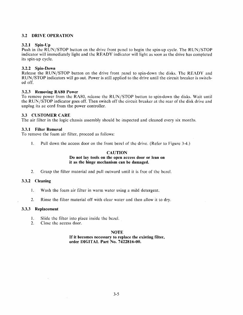
3.2 DRIVE OPERATION
3.2.1 Spin-Up Push in the RUN /STOP button on the drive front panel to begin the spin-up cycle. The RUN/STOP indicator will immediately light and the READY indicator will light as soon as the drive has completed its spin-up cycle.
3.2.2 Spin-Down Release the RUN/STOP button on the drive front panel to spin-down the disks. The READY and RUN /STOP indicators will go out. Power is still applied to the drive until the circuit breaker is switched off.
3.2.3 Removing RA80 Power To remove power from the RA80, release the RUN/STOP button to spin-down the disks. Wait until the RUN/STOP indicator goes off. Then switch off the circuit breaker at the rear of the disk drive and unplug its ac cord from the power controller.
3.3 CUSTOMER CARE The air filter in the logic chassis assembly should be :inspected and cleaned every six months.
3.3.1 Filter Removal To remove the foam air filter, proceed as follows:
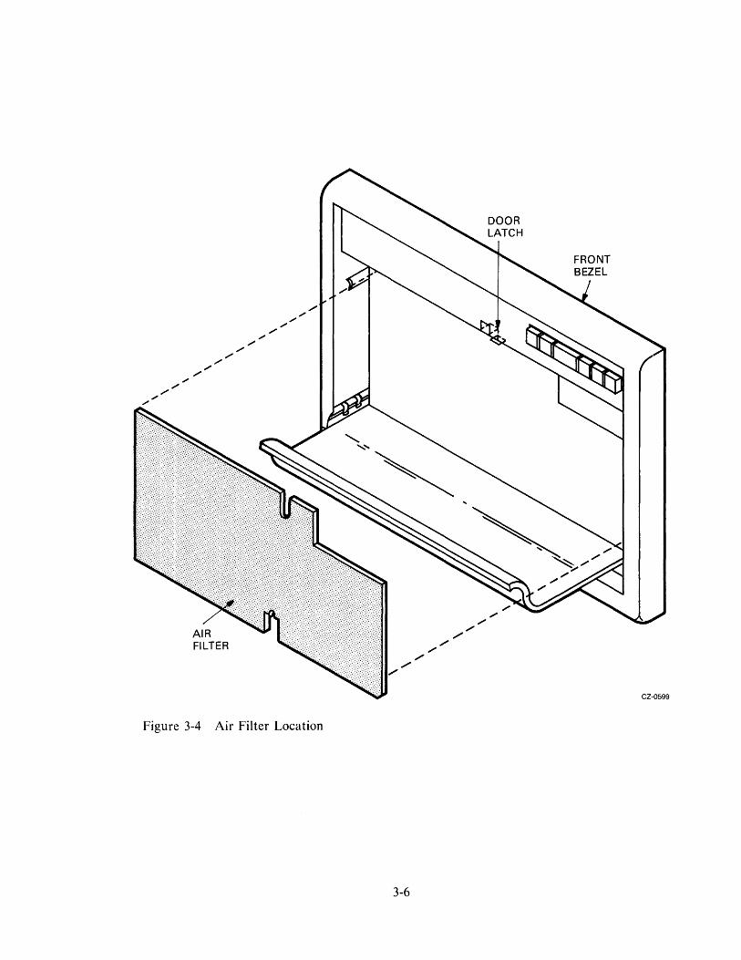
1. Pull down the access door on the front bezel of the drive. (Refer to Figure 3-4.)
CAUTION Do not lay tools on the open access door or lean on it as the hinge mechanism can be damaged.
2. Grasp the filter material and pull outward until it is free of the bezel.
3.3.2 Cleaning
1. Wash the foam air filter in warm water using a mild detergent.
2. Rinse the filter material off with clear water and then allow it to dry.
3.3.3 Replacement
1. Slide the filter into place inside the bezel. 2. Close the access door.
NOTE If it becomes necessary to repllace the existing filter, order DIGITAL Part No. 7422816-00.
3-5
" ;" /
;"
Figure 3-4 Air Filter Location
3-6
" / ,-
" " "
CZ-0599

RASO Disk Drive Subsystem User Guide EK-ORASO-UG-OOI
Reader's Comments
Your comments and suggestions will help us in our contillluous effort to improve the quality and usefulness of our pUblications.
'What is your general reaction to this manual? In your judgment is it complete, accurate, well organized, well written, etc.? Is ~ easy to use? ~~~~~~~~~_~~~~~~~~~~~~~~~~~~~~
What faults or errors have you found in the manual? _, __ ~~~ __ ~~ ______ ~~ __ _
Does this manual satisfy the need you think it was intl!nded to satisfy? ____________ _
Does it satisfy your needs? _______________ _ VVhy? __________________ _
[J Please send me the current copy of the Technical Documentation Catalog, which contains information on the remainder of DIGITAL's technical documentation.
Name ~ __ ~_~ __ ~~ __ ~ __ _ Street ______________ ~ __ _
Title City ________________ ~ __
Company~~ __ ~~~ __ ~~ ______ ~ __ __ State/Country ___________________ _
Department ~ ___ ~~~~ ______ ~ __ _ Zip
Additional copies of this document are available from:
Digital Equipment Corporation 444 VVhitney Street Northboro, Ma 01532 Attention: Communications Services (NR2/M 15)
Customer Services Section
Order No. _E_K_-_O_R_A_S-O--U_G_-_O_Ol _______ ,

- - - - - - - - - - - FoldHere - - - - - - - - - - -
- - - - Do Not Tear - Fold Here and Staple
I II II I
BUSINESS REPLY MAIL FIRST CLASS PERMIT NO.33 MA YNARD. MA.
Educational Services Development and Publishing
POSTAGE WILL BE PAID BY ADDRESSEE
Digital Equipment Corporation 301 Rockrimmon Boulevard South
Colorado Springs, Colorado 80919
No Postage
Necessary
if Mailed in the
United States

Digital Equipment Corporation. Bedford, MA 01730