Embed Size (px)
Citation preview

HEWLETT-PACKARD COMPANYRoseville Networks Division8000 Foothills BoulevardRoseville, California 95678
HP AdvanceNet
lAN3000/V Diagnostic and
Troubleshooting Guide
This Manual Contains
IEEE 802.3 LAN
Diagnostic Software Information
For HP 3000 MPE-V Systems
Flio- HEWLETT~'~ PACKARD
Manual Part Number 30242-90003E0887
Printed in U. S. A.August 1987
2
Notice
The information contained in this document is subject to change without notice.
HEWLETT-PACKARD COMPANY MAKES NO WARRANTY OF ANYKIND WITH REGARD TO THIS MATERIAL, INCLUDING, BUT NOTLIMITED TO, THE IMPLIED WARRANTIES OF MERCHANTABILITYAND FITNESS FOR A PARTICULAR PURPOSE. HEWLETT-PACKARDCOMPANY shall not be lia ble for errors contained herein or for incidental orconsequential damages in connection with the furnishing, performance or use ofthis material.
HEWLETT-PACKARD COMPANY assumes no responsibility for the use orreliability of its software on equipment that is not furnished byHEWLETT-PACKARD COMPANY.
This document contains proprietary information, which is protected bycopyright. All rights are reserved. No part of this document may bephotocopied, reproduced or translated to another language without the priorwritten consent of HEWLETT-PACKARD COMPANY Company.
Copyright © 1987 by HEWLETT-PACKARD COMPANY
Printing History
New editions are complete revisions of the manual. Update packages, which areissued between editions, contain additional and replacement pages to be mergedinto the manual by the customer. The dates on the title page change only whena new edition or a new update is published. No information is incorporated intoa reprinting unless it appears as a prior update; the edition does not change whenan update is incorporated.
The software code printed alongside the date indicates the version level of thesoftware product at the time the manual or update was issued. Many productupdates and fixes do not require manual changes and, conversely, manual corrections may be done without accompanying product changes. Therefore, do notexpect a one-to-one correspondence between product updates and manualupdates.
Edition 1 June 1985 (32189B.51.00)Edition 2 August 1987 (320330.02.01)
3

Preface
This guide describes tools to troubleshoot IEEE 802.3 LAN link hardware connecting HP 3000 MPE-V systems.
The primary tool described is LANDIAG, the HP 3000 Local Area Network (LAN)Diagnostic software utility. If you have a hardware problem on your HP 3000LAN link, you can use LANDIAG along with the other tools to locate the FieldReplaceable Unit (FRU) at fault. You must then repair or replace the faultyFRU.
This guide supplements other LAN troubleshooting manuals, as follows:
1. The LA N Link Hardware Trouhleshooting Manual, IEEE 802.3 CoaxialCable LA N, 5955-7681, covers the troubleshooting of HP ThinLANs andThickLANs (thin and thick coaxial cable LANs) comprised of dissimilar systems (such as HP 1000 RTE-A, HP 9000 Series 300, 500 and 800 HP-UX, andHP 3000 MPE-V systems). It uses a portion of the LANDIAG software information contained here. (The HP CE Handbook version of this manual is5959-2217.)
2. The H P ThinLA N Diagnostics and Troubleshooting Manual for PCs,50909-90060, is directed toward HP personal computer ThinLAN networks.When HP 3000 systems are connected, the LANDIAG information presentedhere is essential.
3. The troubleshooting process for HP StarLAN, featuring twisted-pair cables,is covered by the HP Star/AN Diagnostics and Troubleshooting Manual forpes, 50906-90060. When HP 3000 MPE-V systems are connected toStarLAN, the LANDIAG information presented here is also needed.
4. If the problem lies in LAN software, rather then the hardware, theNS3000/V Network Manager Relerence Manual (32344-90002) should beconsulted.
The intended audiences for this guide include the Network Manager, theNetwork Consultant, the Data Comm Specialist, and the Hewlett-PackardCustomer Engineer (CE) and Systems Engineer (SE).
5
Preface (continued)
How To Use This Guide
All users should read Chapter 1 to become acquainted with general troubleshooting considerations and tools covered by this guide. As a reference manual, userscan subsequently proceed to the chapter describing the particular tool of interest.
For those users who lack troubleshooting procedures, Appendix A is provided.Appendix A provides procedures, as a series of decision-tree flowcharts, to helpisolate HP 3000 LAN link hardware faults. These procedures utilize LANDIAGand other tools presented in the various chapters.
Organization Of This Guide
This guide consists of the following chapters:
Chapter 1: General Information
Chapter 2: SHOWCOM
Chapter 3: Activity LEOs
Chapter 4: LAN Node Diagnostic
Chapter 5: LANIC Self Test
Chapter 6: Tracing
Chapter 7: Software Tools
Appendix A: Troubleshooting Flowcharts
6
Preface (continued)
Additional References
When using this manual, you should be familiar with the basic operating principles of HP 3000 computers and the MPE-V operating system. In addition, youshould be familiar with the subjects covered in the following manuals, asappropriate:
• HP 3000 Computer Systems, MPE V Commands Reference Manual(32033-90006)
• HP 3000 Computer Systems, MPE V Intrinsics Reference Manual(32033-90007).
• HP 3000 Computer Systems, MPE V System Operation and ResourceManagement Reference Manual (32033-90005)
• Fundamental Data Communications Handbook (5979-4634)
• LAN Cable and Accessories Installation Manual (5955-7680), for coaxialcable LANs
• HP 3000 LAN Link installation and service manuals, including- HP 30240A LAN3000/V Link LANIC Installation and Service Manual
(part number depends on the product option selected)- HP 30265A StarLAN/3000 Link Installation and Service Manual
(30265-90001), for Series 37 and MICRO 3000 systems
• NS3000/V Network Manager Reference Manual (Volume 1, 32344-90002;Volume 2, 32344-90012)
• NS3000/V User/Programmer Reference Manual (32344-90001)
• NS3000/V Error Message and Recovery Manual (32344-90005)
• HP StarLAN Planning Guide for PCs (50906-90020)
• HP SiteWire Planning Guide (5959-2201)
7

j
jjjjjjjjjjjjjjjjjjjjjjjjjjjjjjjjjjjjjjjjjjjjjjjjjjjjjjjjjjjJ
Chapter 1General Information
Contents
Page1-1
Introduction 1-1Applicable Networks 1-3
Coaxial Cable LANs 1-3Twisted Pair LAN 1-3
Fault Isolation and Repair Strategy 1-4Network Map 1-5Abbreviations and Nomenclature 1-6
Chapter 2SHOWCOM
Page2-1
Syntax 2-1Interpreting Results 2-2
Transn1it Fields 2-2Receive Fields 2-3Errors 2-4
Chapter 3Activity LEDs
Page3-1
Cable Interface Activity LEOs 3-5The E and L Indicators 3-6Relationship to Cable Signals 3-7MPU Activity LEOs 3-9
Network Fault LED Examples 3-12Coaxial Cable LAN 3-12StarLAN 3-15
Chapter 4LAN Node Diagnostic
Page4-1
General Information 4-1What is the LAN Node Diagnostic? 4-1Required Hardware 4-1Required Software 4-2Execution Time 4-2Tests Included 4-3Diagnostic Limitations 4-4
9
Contents (continued)
Guidelines for Setting Up and Using LANDIAG 4-6System Infornlation 4-6Capability Levels 4-6System Type Check 4-7Operation with Network Services 4-7Reliability and Recovery from Power Failure , 4-8Integrity of the System 4-8Running LANDIAG .4-10User Interface 4-12Activity Indicator 4-12How to Get Output From LANDIAG 4-13Station (Link-Level) Addresses 4-14
Command Set 4-15Diagnostic Dialogue Example 4-17Command Entry Abbreviations 4-19Fault Messages 4-19HELP Command 4-20EXIT Command 4-21GO Command 4-21LOOP Command 4-21NOPRINT Command , 4-22PRINT' Command 4-22TEST NIALL Command .4-22
Test Descriptions 4-23Test #1. Roll Call Test 4-24Test #2. Channel ID Test 4-25Test #3. Initialization Test .4-26Test #4. Self Test. 4-27Test #5. Interrupt Test .4-29Test #6. Soft Reset Test .4-30Test #7. CR-SR Loop Test .4-31Test #8. Bus Conflict Test .4-33Test #9. Address Offset Test .4-34Test #10. Extended Address Test .4-36Test #1 L FIFO Write Test. .4-38Test #12. FIP Conflict Test. 4-40Test #13. Coprocessor Test .4-42Test #14. MAU Loopback Test. .4-44Test #15. Date Code Test. .4-51Test #16. Hood Loopback Test .4-52Test #17. Remote Node Test. .4-63
Error Messages 4-74
10
Chapter 5LANIC Self Test
Contents (continued)
Page5-1
The Scope of LANIC Card Self Test. 5-1Self Test Limitations 5-2How To Read Selftest LEDs 5-2How To Use the Self Test 5-4
Chapter 6Tracing
Page6-1
General Information 6-1Linkcontrol Trace=On 6-2
Syntax 6-2Parameters 6-2Discussion 6-3Example 6-3
Linkcontrol Trace=Off 6-4Syntax 6-4Parameters : 6-4Discussion 6-4Example 6-4
Using CSDUMP Formatting Program 6-5Defining a Trace File for CSDUMP 6-6Defining a CSDUMP Listing File 6-6Initiation the CSDUMP Program 6-7Formatted CSDUMP Trace Listing 6-7CSDUMP Listing Header Message 6-8Begin Tracing and Line Information Messages 6-9Trace Record and Header Message 6-10Trace Entry Format 6-11Missing Entries Message 6-12Trace Entry Mnemonics 6-12PSCT (PRCT) Trace Entries 6-14PCMP Trace Entries 6-17End of Trace and Line Information Messages 6-19
CS Error Codes 6-20
11
Contents (continued)
Chapter 7Software Tools
Page7-1
M~mory Dump 7-1NSDPAN5/NSDUMPJ 7-1
Obtaining an NSDPAN5 Listing 7-1LISTLOG5 7-2
Operation of LISTLOG5 ' 7-2NMMAINT 7-5
Example '.' 7-6CSLIST 7-10
Example 1 7-10Example 2 7-11Example 3 7-12
DSLIST 7-13Example 7-14
Appendix ATroubleshooting FIO\ychal·ts
PageA-I
Introduction A-ILAN Node Diagnostic Flowcharts A-3Using Test 17 - The Remote Node Test (RNT) A-22Using Software Line Tests A-23
12

Figure or Flowchart
Figures and Tables
Page
Figure 1-1. LAN Hardware Troubleshooting Complexity 1-1Figure 3-1. LANIC Card LEOs On Series 4X/5X/6X/70 Systems 3-1Figure 3-2. LANIC Card LEOs On Series 37 and MICR03000 Systems 3-2Figure 3-3. LED Labels and Functions 3-3Figure 4-1. Running LANDIAG .4-10Figure 4-2. Program State Diagram .4-11Figure 4-3. Selftest Error Message Example .4-28Figure 4-4. StarLAN Loopback Connector. .4-49Figure 4-5. StarLAN Connection Fault Isolation Using Test 14 .4-50Figure 4-6. Loopback Hood on MAU .4-53Figure 4-7. Loopback Hood on ThinMAU .4-53Figure 4-8. Testing AUI Cable Sections 4-61Figure 6-1. Trace Listing Header 6-8Figure 6-2. Begin Tracing and Line Information Messages 6-9Figure 6-3. Trace Record Header 6-10Figure 6-4. Sample Trace Entry 6-11Figure 6-5. PRCT Trace Entry 6-14Figure 6-6. PRCT and PSCT Formats 6-16Figure 6-7. PCMP Trace Entry 6-17Figure 6-8. End of Trace and Closing Line Information 6-20Figure A-I. Hardware Troubleshooting Overview A-2Figure A-2. Software Line Tests A-23
Flowchart 1. Verification of System and Hardware Configuration A-5Flowchart 2. LANIC Initialization and Main Module Verification A-7Flowchart 3. Interrupt, Soft Reset, and SIMB/IMB Interface Verification A-9Flowchart 4. LAN Coprocessor, Loopback and Date Code Verification A-IIFlowchart 5. Identifying Failed FRUin Hood Loopback Test A-I3Flowchart 6. Identifying MAU/ThinMAU Power-On Faults A-I5Flowchart 7. Testing Coax LAN Connection AU! Interface A-I7Flowchart 8. Testing AUI Cables A-I9Flowchart 9. Testing MAU/ThinMAU Connection A-21
13

Figures and Tables (continued)
ThWe hp
Table 3- I. LED Description During Normal Operation 3-4Table 3-2. Approximate Duration References 3-7Table 3-3. AUI Cable Activity LEOs and Possible Causes on Transmit. 3-15Table 3-4. StarLAN Cable Activity LEDs and Possible Causes on Transmit .. 3-17Table 4-1. LAN Node Diagnostic Tests 4-3Table 4-2. Test Dependencies 4-9Table 4-3. Test Dependencies .4-16Table 5-1. Selftest LEDs and Subtest Descriptions 5;'7Table 5-2. Reporting of Unexpected Results from Self Test. 5-10Table 6-1. CSDUMP Error Message Parameter 6-:5Table 6-2. Trace Entry Type Mnemonics 6-13Table 6-3. Function Codes 6-18Table 6-4. Code Meaning of Irrecoverable Errors 6-20Table 6-5. Code Meaning of Recovered Errors 6-21
14
NOTATION
UPPERCASEBoldface
italics
lowercasenonbold
[ ]
{ }
Conventions Used
DESCRIPTION
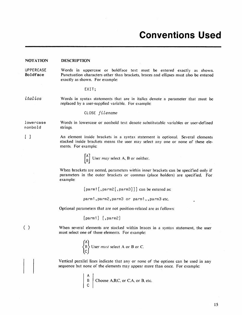
Words in uppercase or boldface text must be entered exactly as shown.Punctuation characters other than brackets, braces and eHipses must also be enteredexactly as shown. For example:
EXIT;
Words in syntax statements that are in italics denote a parameter that must bereplaced by a user-supplied variable. For example:
CLOSE filename
Words in lowercase or nonbold text denote substitutable variables or user-definedstrings.
An element inside brackets in a syntax statement is optional. Several elementsstacked inside brackets means the user may select anyone or none of these elements. For example:
[~] User may select A, B or neither.
When brackets are nested, parameters within inner brackets can be specified only ifparameters in the outer brackets or commas (place holders) are specified. Forexample:
[ pa rm 1 [ , pa rm2 [ , pa rm3] ]] can be entered as:
parm 1,pa rm2, pa rm3 or pa rm1 , ,pa rm3 etc.
Optional parameters that are not position-related are as follows:
[ pa rm 1] [, pa rm2]
When several elements are stacked within braces in a syntax statement, the usermust select one of those elements. For example:
{ ~} User must select A or B or C.
Vertical parallel lines indicate that any or none of the options can be used in anysequence but none of the elements may appear more than once. For example:
AB Choose A,B,C, or C,A, or B, etc.C
15
Conventions Used (continued)
NOTATION
underlining
[CONTROLlohar
16
DESCRIPTION
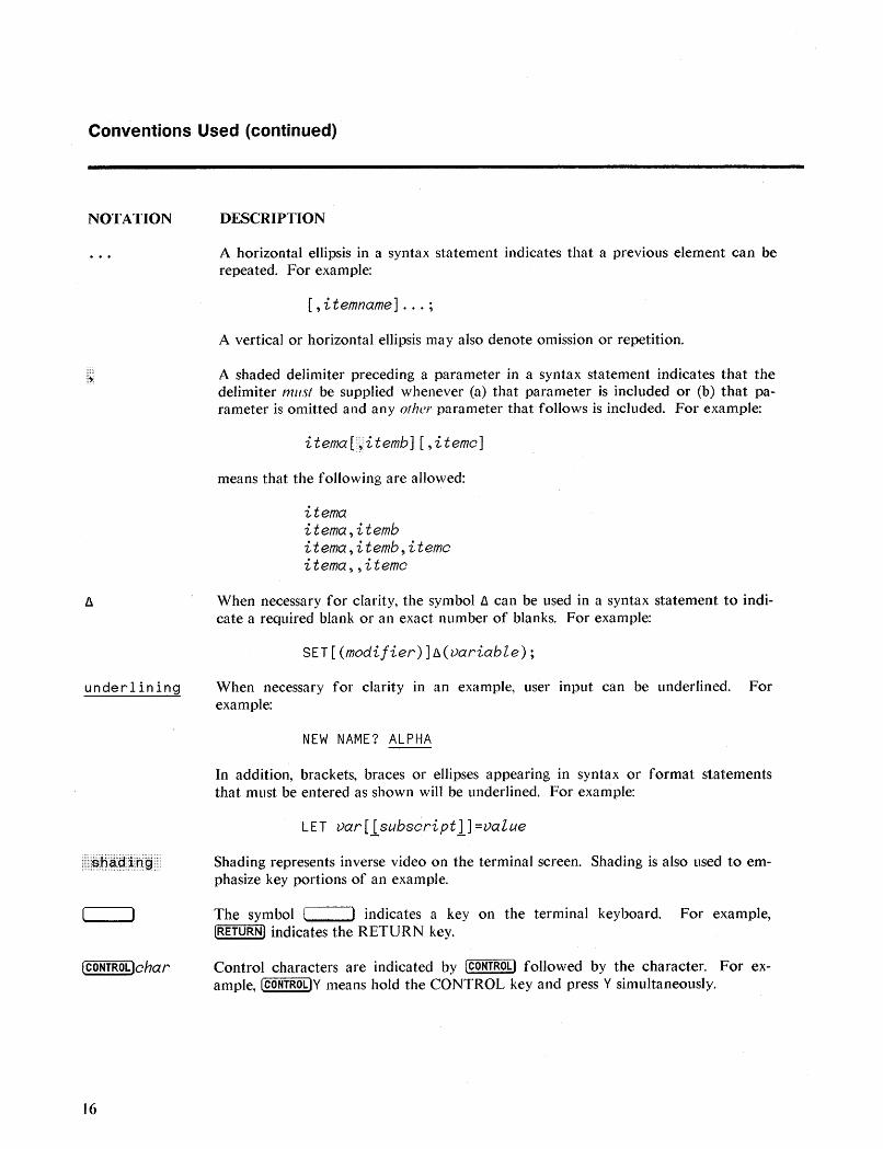
A horizontal ellipsis in a syntax statement indicates that a previous element can berepeated. For example:
[, itemname] ... ;
A vertical or horizontal ellipsis may also denote omission or repetition.
A shaded delimiter preceding a parameter in a syntax statement indicates that thedelimiter must be supplied whenever (a) that parameter is included or (b) that parameter is omitted and any other parameter that follows is included. For example:
i tema [~i temb] [ ,itemc]
means that the following are allowed:
itemaitema,itembitema,itemb,itemoitema , , itemo
When necessary for clarity, the symbol fJ. can be used in a syntax statement to indicate a required blank or an exact number of blanks. For example:
SET[(modijier)]fJ.(variable);
When necessary for clarity in an example, user input can be underlined. Forexample:
NEW NAME? ALPHA
In addition, brackets, braces or ellipses appearing in syntax or format statementsthat must be entered as shown will be underlined. For example:
LET var[lsubscriptl]=value
Shading represents inverse video on the terminal screen. Shading is also used to emphasize key portions of an example.
The symbol [ ) indicates a key on the terminal keyboard. For example,[RETURN) indicates the RETURN key.
Control cha.racters are indicated by [CONTROL) followed by the character. For example, [CONTROLlY means hold the CONTROL key and press Y simultaneously.
Reader' Comment Sheet
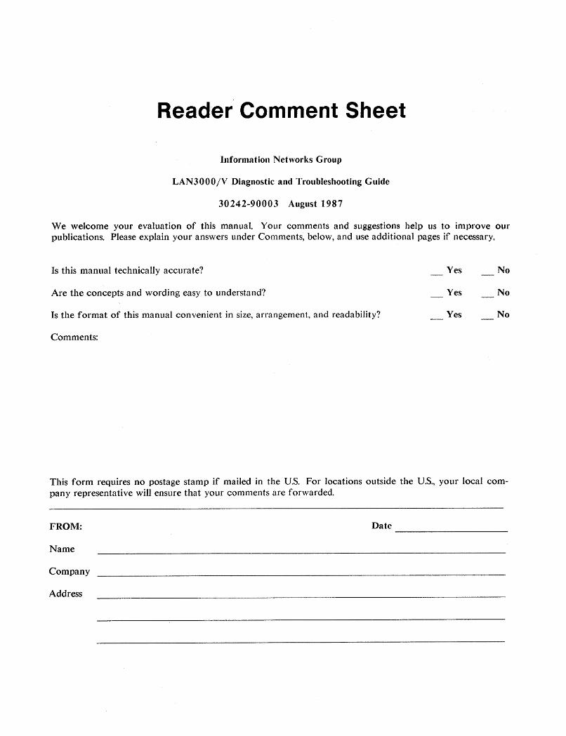
Information Networks Group
LAN3000/V Diagnostic and Troubleshooting Guide
30242-90003 August 1987
We welcome your evaluation of this manual. Your comments and suggestions help us to improve ourpublications. Please explain your answers under Comments, below, and use additional pages if necessary.
Is this manual technically accurate?
Are the concepts and wording easy to understand?
Is the format of this manual convenient in size, arrangement, and readability?
Comments:
Yes
Yes
Yes
No
No
No
This form requires no postage stamp if mailed in the U.S. For locations outside the U.S., your local company representative will ensure that your comments are forwarded.
FROM:
Name
Company
Address
Date -----------
FOLD
FOLD
111111
BUSINESS REPLY MAILFIRST CLASS PERMIT NO. 256 ROSEVILLE, CALIFORNIA
POSTAGE WILL BE PAID BY ADDRESSEE
Publications ManagerHEWLETT-PACKARD COMPANYRoseville Networks Division8000 Foothills BoulevardRoseville, California 95678-6598
NO POSTAGENECESSARYIF MAILED
IN THEUNITED STATES
FOLD
FOLD
General Information 1
Introduction
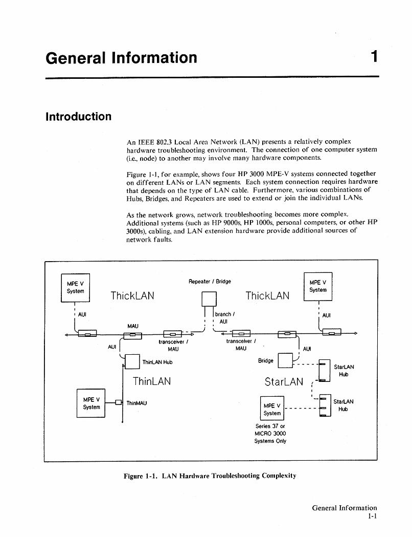
An IEEE 802.3 Local Area Network (LAN) presents a relatively complexhardware troubleshooting environment. The connection of one computer system(i.e., node) to another may involve many hardware components.
Figure 1-1, for example, shows four HP 3000 MPE-V systems connected togetheron different LANs or LAN segments. Each system connection requires hardwarethat depends on the type of LAN cable. Furthermore, various combinations ofHubs, Bridges, and Repeaters are used to extend or join the individual LANs.
As the network grows, network troubleshooting becomes more complex.Additional systems (such as HP 9000s, HP 1000s, personal computers, or other HP3000s), cabling, and LAN extension hardware provide additional sources ofnetwork faults.
MPE V IhtJ StarLAN------- Hub
System
Repeater I Bridge
ThinLAN Hub
ThinLAN
ThinMAU
ThickLAN
MPE VSystem
II
I AUI
MPE VSystem
MPE VSystem
~branchl ThickLAN : AUI
<f----i::::=:e=I:=::I----F=l:F~---f--c:J--I~- -i>-) ~ A4-4
U
_'-+-csa--c:>-lf-----+9<::J--+----b-l=:::C:J=:f---(lotransceiver I
MAU AUI
Bridge nJ LJL-F- - - - - StarLAN
Hub
StarLAN (-I
series 37 orMICRO 3000Systems Only
Figure 1-1. LAN Hardware Troubleshooting Complexity
General Information1-1
General Information1-2
Various tools are available on MPE-V systems to assist in the LANtroubleshooting process. As they pertain to LAN troubleshooting, the followingtools are described in this manual:
• SHOWCOM: for monitoring the communication line.
• Activity LEDs: for monitoring activity on AUI or StarLAN node cabling,and on the LANIC card.
• LANDIAG: the LAN Diagnostic program for testing composite LAN linkhardware.
• Self Test and selftest LEDs: primarily used for testing the LANIC cardcircuitry.
• Tracing: for analyzing protocol activity of the network at the link level.
• Memory Dump: for analyzing a system crash in relation to a LANproblem.
• NSDPAN5/NSDUMPJ: for formatting memory dumps.
• LISTLOG5: for analyzing the system log.
• NMMAINT: for analyzing the NMS log.
• CSLIST: for checking the version of communications software.
• DSLIST: for obtaining a list of DS software module versions.
Applicable Networks
The tools provided in this guide are described as they pertain to troubleshootingLANs that conform to Hewlett-Packard implementations of the IEEE 802.3standards. These LANs feature baseband signaling, and a Carrier Sense MultipleAccess with Collision Detection (CSMA/CD) network access protocol.
Coaxial Cable LANs
Hewlett-Packard coaxial cable LANs feature 10-megabit per second bursttransfer rates over a coaxial cable bus to which each node attaches.
IEEE 802.3 Type 10BASES Standard
This LAN uses a "thick" (0.4 inch/IO mm diameter) coaxial cable. Thick cableLANs feature connection of up to 100 nodes on a single 500 metre bus segment.
HP 3000 MPE-V systems connect to this LAN using the HP LAN3000/V linkproduct. Hardware included with this product consist of a Local Area NetworkInterface Controller (LANIC) interface card, an Attachment Unit Interface(AUI) cable, and an HP 30241A Medium Attachment Unit (MAU) and tapassembly for cable access.
IEEE 802.3 Type 10BASE2 Standard
This LAN uses a "thin" This LAN uses a "thin" (0.19 inch/4.9 mm diameter) RG58C/U coaxial cable. ThinLAN cables feature connection of up to 30 nodes on asingle 185 metre bus segment.
HP 3000 MPE-V systems connect to this LAN using the HP ThinLAN3000/Vlink product. Applicable hardware consists of the LANIC interface card\ and HP28641A ThinMAU and BNC tee connector for cable access.
Twisted Pair LAN
IEEE 802.3 Type 1BASES Standard (Proposed)
The Hewlett-Packard twisted pair cable LAN, HP StarLAN, features a I-megabitper second burst transfer rate through a hierarchical structure of HP 27212AStarLAN Hubs. Nodes connect to the Hubs via the twisted pair cables; eachcable can be up to 250 metres in length.
HP 3000 MPE-V systems (Series 37 and MICRO 3000 systems only) connect tothis LAN using the HP StarLAN3000/V link product. Applicable hardwareconsists of the interface card, and twisted pair cable ordered separately.
General Information1-3

Fault Isolation and Repair StrategyLAN hardware faults must be located and corrected. Because LANs arecomprised of many pieces of hardware, faults must identified to the fieldreplaceable unit (FRU) level of assembly. If the faulty FRU cannot beimmediately corrected, it is replaced with a new or functional unit. (For repair,replacement, or return procedures, consult the installation or service manual forthe failed unit.)
LAN faults can be classified into two categories: Node faults, and Networkfaults. A Node fault is characterized by a single node failure that does notaffect the other nodes on the network. A Network fault is characterized bymultiple node failures, where it is likely that a piece of hardware used commonlyby the nodes has failed. Fault isolation procedures for both types of faults areneeded.
The following manuals provide both node and network fault isolationprocedures. They are differentiated by the type of network to which they apply.
For coaxial cable LANs, refer to the LA AT Link Hardware TroubleshootingManual, 5955-7681. (HP CE Handbook version, 5959-2217.)
For HP StarLAN, refer to the HP StarLAN Diagnostics and TroubleshootingGuide for PCs, 50906-90060.
Appendix A of this guide provides fault isolation procedures, in flowchartformat, for HP 3000 MPE-V links. Although network considerations are notexcluded, these procedures focus on MPE-V link Node faults. They complementthe above troubleshooting manuals by providing an alternative set of proceduresthat use more features of the tools described in this guide.
General Information1-4
Network MapWhen troubleshooting a network, the availability of a network map will be
critical, especially for large complex networks. As required by Hewlett-Packard,
the network map should have been developed during the configuration of the
network, and maintained to reflect any growth or modification.
A network map provides the physical layout of nodes on the network, including
distances from one to another. Physical layout means the placement of all
cables, MAUs and Taps, Hubs and all related network computer equipment. In
addition, the network map should be labeled with relevant node information,
including node names, globally administered station addresses, and any locally
administered station addresses. The configuration of relevant network software
on each node would be helpful.
If a network map is not available, you should make one. Refer to the
NS3000/V Network Manager Relerence Manila! (Volume 1,32344-90002;
Volume 2, 32344-90012) for information on addresses and other configured items
included in the network map. Also, refer to the H P SiteWire Planning Guide
(5959-2201) for additional information.
General Information1-5
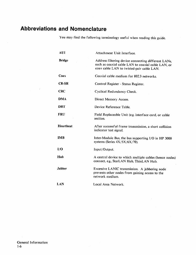
Abbreviations and NomenclatureYou may find the following terminology useful when reading this guide.
General Information1-6
AUI
Bridge
Coax
CR-SR
eRC
DMA
DRT
FRU
Heartbeat
1MB
I/O
Hub
Jabber
LAN
Attachment Unit Interface.
Address filtering device connecting different LANs,such as coaxial cable LAN to coaxial cable LAN, orcoax cable LAN to twisted-pair cable LAN.
Coaxial cable medium for 802.3 networks.
Control Register - Status Register.
Cyclical Redundancy Check.
Direct Memory Access.
Device Reference Table.
Field Replaceable Unit (e.g. interface card, or cablesection.
After successful frame transmission, a short collisionindicator test signal.
Inter-Module Bus, the bus supporting I/O in HP 3000systems (Series 4X/5X/6X/70).
Input/Output.
A central device to which multiple cables (hence nodes)connect, e.g., StarLAN Hub, ThinLAN Hub.
Excessive LANIC transmission. A jabbering nodeprevents other nodes from gaining access to thenetwork medium.
Local Area Network.
LANIC
LED
Loopback
MAU
MAUPON
MAUPS
MC
Monitor
NMI
MPU
Node
NS
OBII
RNT
SIMB
SPU
STREG
Twisted-pair
Local Area Network Interface Controller for IEEE802.3 LAN I/O (the interface card in HP 3000 MPE-Vsystems).
Light Emitting Diode.
Transmission and receipt of data to verify operation ofthe communication path.
Medium Attachment Unit, a device that provides theLANIC with access to a coaxial cable medium.
MAU Power On signal.
MAU Power Sense signal.
A multicast message; a type of broadcast message sent toa group of stations, but not necessarily to all the stations.
RAM resident Z80 code used together with the self testin order to upload detailed test results to the HP 3000.
Non-Maskable Interrupt.
A Z80 microprocessor on the LANIC.
Uniquely addressable station on a LAN.
HP Network Services for the HP3000.
Obtain Interrupt - An IMB/SIMB command.
Remote Node Test.
Synchronous Inter-Module Bus, the bus connecting theCPU, Memory, and 1/0 in HP 3000 Series 37 andMICRO 3000 systems.
System Processor Unit on HP 3000.
Self Test Register.
Twisted-pair cable for IEEE 802.3 networks.
General Information1-7

SHOWCOM 2
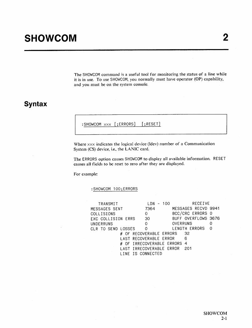
The SHOWCOM command is a useful tool for monitoring the status of a line whileit is in use. To use SHOWCOM, you normally must have operator (OP) capability,and you must be on the system console.
Syntax
:SHOWCOM xxx [;ERRORS] [;RESET]
Where xxx indicates the logical device (ldev) number of a CommunicationSystem (CS) device, i.e., the LANIC card.
The ERRORS option causes SHOWCOM to display all available information. RESETcauses all fields to be reset to zero after they are displayed.
For example:
:SHOWCOM 100;ERRORS
TRANSMIT LON - 100 RECEIVEMESSAGES SENT 7364 MESSAGES RECVD 9941COLLISIONS 0 BCC/CRC ERRORS 0EXC COLLISION ERRS 30 BUFF OVERFLOWS 3676UNDERRUNS 0 OVERRUNS 0CLR TO SEND LOSSES 0 LENGTH ERRORS 0
# OF RECOVERABLE ERRORS 32LAST RECOVERABLE ERROR 6# OF IRRECOVERABLE ERRORS 4LAST IRRECOVERABLE ERROR 201LINE IS CONNECTED
SHOWCOM2-1
Interpreting Results
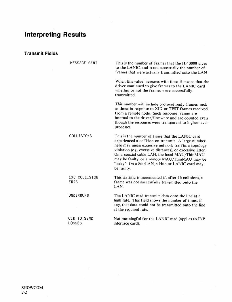
Transmit Fields
MESSAGE SENT
COLLISIONS
EXC COLLISIONERRS
UNDERRUNS
CLR TO SENDLOSSES
SHOWCOM2-2
This is the number of frames that the HP 3000 givesto the LANIC, and is not necessarily the number offrames that were actually transmitted onto the LAN
When this value increases with time, it means that thedriver continued to give frames to the LANIC cardwhether or not the frames were successfullytransmitted.
This number will include protocol reply frames, suchas those in response to XID or TEST frames receivedfrom a remote node. Such response frames areinternal to the driver/firmware and are counted eventhough the responses were transparent to higher levelprocesses.
This is the number of times that the LANIC cardexperienced a collision on transmit. A large numberhere may mean excessive network traffic, a topologyviolation (e.g., excessive distances), or excessive jitter.On a coaxial cable LAN, the local MAU/ThinMAUmay be faulty, or a remote MAU/ThinMAU may be"leaky." On a StarLAN, a Hub or LANIC card maybe faulty.
This statistic is incremented if, after 16 collisions, aframe was not successfully transmitted onto theLAN.
The LANIC card transmits data onto the line at ahigh rate. This field shows the number of times, ifany, that data could not be transmitted onto the lineat the required rate.
Not meaningful for the LANIC card (applies to INPinterface card).
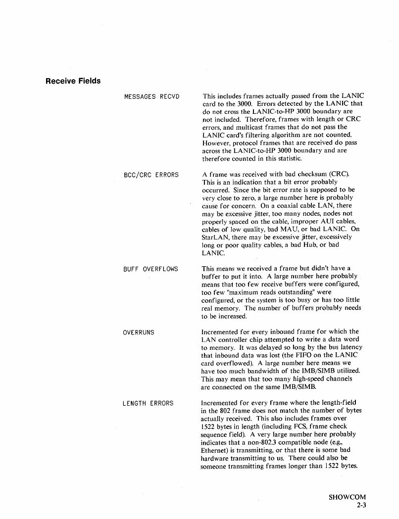
Receive Fields
MESSAGES RECVD
BCC/CRe ERRORS
BUFF OVERFLOWS
OVERRUNS
LENGTH ERRORS
This includes frames actually passed from the LANICcard to the 3000. Errors detected by the LANIC thatdo not cross the LANIC-to-HP 3000 boundary arenot included. Therefore, frames with length or CRCerrors, and multicast frames that do not pass theLANIC card's filtering algorithm are not counted.However, protocol frames that are received do passacross the LANIC-to-HP 3000 boundary and aretherefore counted in this statistic.
A frame was received with bad checksum (CRC).This is an indication that a bit error probablyoccurred. Since the bit error rate is supposed to bevery close to zero, a large number here is probablycause for concern. On a coaxial cable LAN, theremay be excessive jitter, too many nodes, nodes notproperly spaced on the cable, improper AUI cables,cables of low quality, bad MAU, or bad LANIC. OnStarLAN, there may be excessive jitter, excessivelylong or poor quality cables, a bad Hub, or badLANIC.
This means we received a frame but didn't have abuffer to put it into. A large number here probablymeans that too few receive buffers were configured,too few "maximum reads outstanding" wereconfigured, or the system is too busy or has too littlereal memory. The number of buffers probably needsto be increased.
Incremented for every inbound frame for which theLAN controller chip attempted to write a data wordto memory. It was delayed so long by the bus latencythat inbound data was lost (the FIFO on the LANICcard overflowed). A large number here means wehave too much bandwidth of the IMB/SIMB utilized.This may mean that too many high-speed channelsare connected on the same IMB/SIMB.
Incremented for every frame where the length-fieldin the 802 frame does not match the number of bytesactually received. This also includes frames over1522 bytes in length (including FCS, frame checksequence field). A very large number here probablyindicates that a non-802.3 compatible node (e.g.,Ethernet) is transmitting, or that there is some badhardware transmitting to us. There could also besomeone transmitting frames longer than 1522 bytes.
SHOWCOM2-3
Errors
# OF RECOVERABLEERRORS
LAST RECOVERABLEERROR
# OF IRRECOVERABLEERRORS
LAST IRRECOVERABLEERROR
The number of errors reported by the driver that didnot cause the link to be disconnected.
This gives the last non-zero CS error number returnedby the driver. The completion status can be anythingother than IRRECOVERABLE ERROR (completionstatus 3) or CATASTROPHE (completion status 5).This includes CS "recoverable error codes" as well aserror numbers that are normally "irrecoverable errorcodes" but were completed with good status so as notto cause the translator to shut down the link.
The number of errors that would force the link to bedisconnected, e.g., on a coaxial cable LAN, could notturn on MAU/ThinMAU power.
This is the last non-zero CS error code that the drivergave when it completed a request withIRRECOVERABLE ERROR (completion status 3) orCATASTROPHE (completion status 5).
This will not be updated for CS error codes 63 and64, since these are not really "errors" but are normalcompletion codes for ABORTIO (function code 66),generated on all process terminations (called fromEXPIRE), and the HARD ABORT, generated whenthe translator detects other errors.
The line will always be in anyone of four states: '
SHOWCOM2-4
(1) CONNECTED
(2) DISCONNECTED
(3) CLOSED
(4) UNDEFINED
The driver is active, firmware has been downloadedand command and response queues have beeninitialized. Basically, the driver and hardware areready to receive and transmit frames.
The driver and hardware have not finishedinitializing or an irrecoverable error has occurred.Basically, the driver and hardware are not ready toreceive and transmit frames.
The LDEV is not allocated (not in use).
Software error.

Activity LEOs 3
There are 15 LEDs located on the edge of each LANIC card. Figures 3-1 and 3-2show the LED locations for Series 4Xj5Xj6Xj70 and Series 37jMICR03000systems, respectively.
A 8 co, , G H I J K L .. N. LANIC TEST.. 0 c (RESET)
~I ...u..l...o..l...u..l~ a! I d i 0 I: lii ISW1 I000000000000000
LEOs
Figure 3-1. LANIC Card LEDs On Series 4Xj5Xj6Xj70 Systems
Activity LEDs3-1
P1 ,-
LEOs
RFI Clip
Activity LEOs3-2
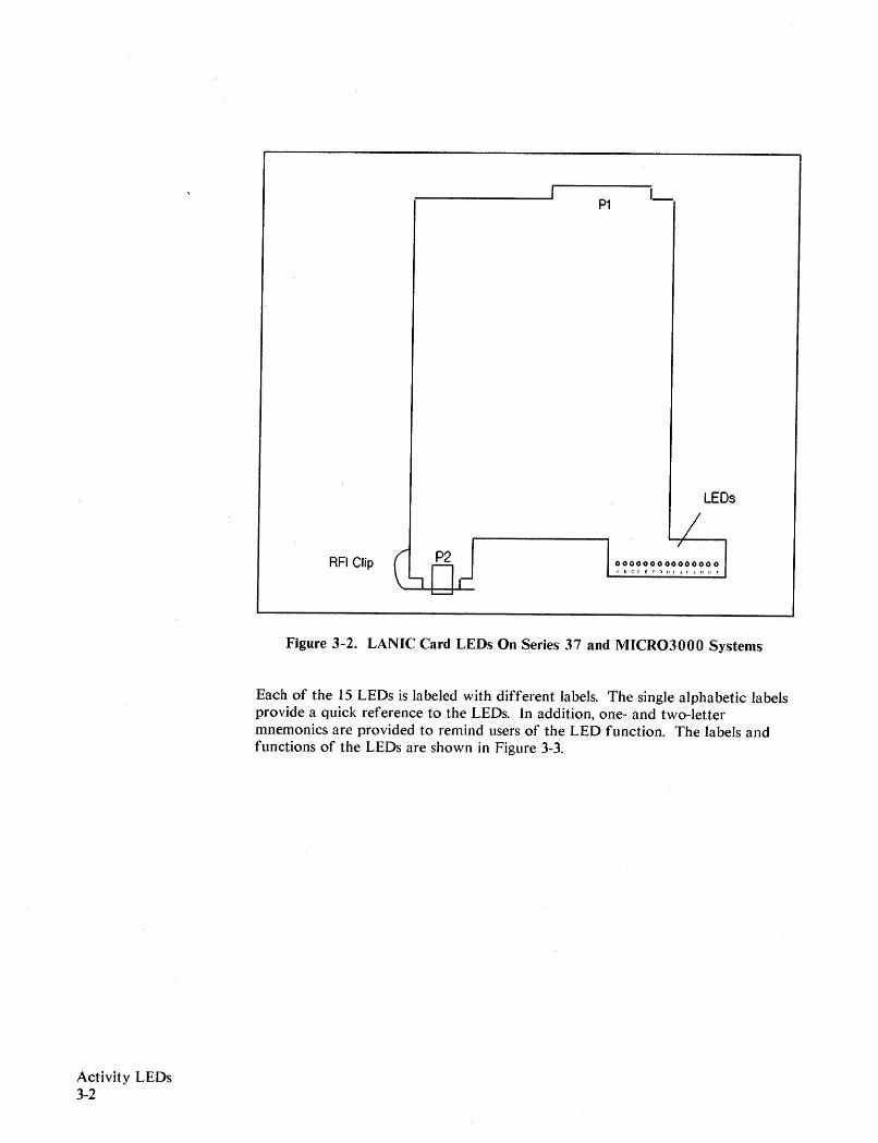
Figure 3-2. LANIC Card LEOs On Series 37 and MICR03000 Systems
Each of the 15 LEOs is labeled with different labels. The single alphabetic labelsprovide a quick reference to the LEOs. In addition, one- and two-lettermnemonics are provided to remind users of the LEO function. The labels andfunctions of the LEOs are shown in Figure 3-3.
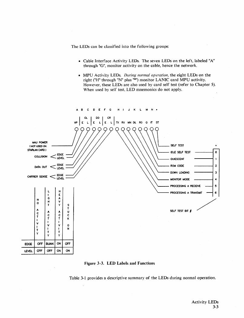
The LEDs can be classified into the following groups:
• Cable Interface Activity LEDs. The seven LEDs on the left, labeled "A"through "G", monitor activity on the cable, hence the network.
• MPU Activity LEDs. During normal operation, the eight LEDs on theright ("H" through "N" plus "*") monitor LANIC card MPU activity.However, these LEDs are also used by card self test (refer to Chapter 5).When used by self test, LED mnemonics do not apply.
AS co E F' G HI J K L M Nfl
EDGEDATA OUT < LEVEL
CARRIER SENSE < EDGELEVEL
..------10
---~3
-----12
-----i 4
QUIESCENT
IDLE SELF' TEST
ROM CODE
DOWN LOADING
PROCESSING A TRANSMIT - 6
PROCESSING A RECEIVE - 5
'---- MONITOR MODE
SELF' TEST BIT ,
vp IE CLL IE DOL IE CRL ITX RX MN DL RO Q IT ST
~________ SELF' TEST
< EDGELEVELCOLLISION
MAU POWER(NOT USED ON
STARLAN CARD )
L H
I E
N G A
0 H VT y S
A T
C A A U
T C C C
I T T K
V I I
I V V 0
T I I N
Y T Ty y
EDGE OFF BLINK ON OFF
LEVEL OFF OFF ON ON
Figure 3-3. LED Labels and Functions
Table 3-1 provides a descriptive summary of the LEDs during normal operation.
Activity LEDs3-3
Activity LEDs3-4
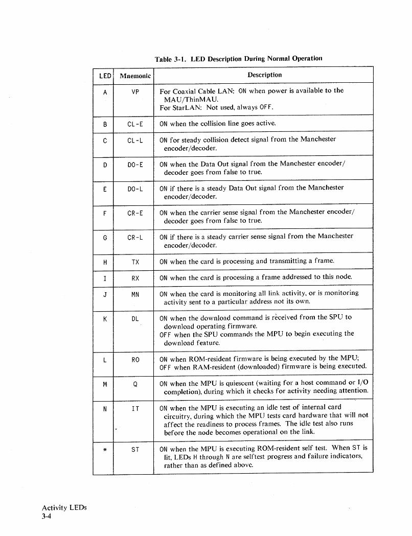
Table 3-1. LED Description During Normal Operation
LED Mnemonic Description
A VP For Coaxial Cable LAN: ON when power is available to theMAU/ThinMAU.
For StarLAN: Not used, always OF F.
B CL-E ON when the collision line goes active.
C CL-L ON for steady collision detect signal from the Manchesterencoder/decoder.
0 OO-E ON when the Data Out signal from the Manchester encoder/decoder goes from false to true.
E OO-L ON if there is a steady Data Out signal from the Manchesterencoder/decoder.
F CR-E ON when the carrier sense signal from the Manchester encoder/decoder goes from false to true.
G CR-L ON if there is a steady carrier sense signal from the Manchesterencoder/decoder.
H TX ON when the card is processing and transmitting a frame.
r RX ON when the card is processing a frame addressed to this node.
J MN ON when the card is monitoring all link activity, or is monitoringactivity sent to a particular address not its own.
K DL ON when the download command is received from the SPU todownload operating firmware.
OF F when the SPU commands the MPU to begin executing thedownload feature.
L RO ON when ROM-resident firmware is being executed by the MPU;OF F when RAM-resident (downloaded) firmware is being executed.
M Q ON when the MPU is quiescent (waiting for a host command or I/Ocompletion), during which it checks for activity needing attention.
-N IT ON when the MPU is executing an idle test of internal card
circuitry, during which the MPU tests card hardware that will not
.' affect the readiness to process frames. The idle test also runsbefore the node becomes operational on the link.
* 8T ON when the MPU is executing ROM-resident self test. When 5T islit, LEOs H through N are selftest progress and failure indicators,rather than as defined above.
Cable Interface Activity LEOs
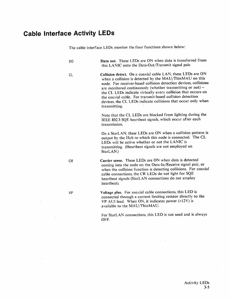
The cable interface LEDs monitor t.he four functions shown below:
DO
CL
CR
VP
Data out. These LEDs are ON when data is transferred fromthis LANIC onto the Data-Out/Transmit signal pair.
Collision detect. On a coaxial cable LAN, these LEOs are ONwhen a collision is detected by the MAU/ThinMAU on thisnode. For receiver-based collision detection devices, collisionsare monitored continuously (whether transmitting or not) -the CL LEOs indicate virtually every collision that occurs onthe coaxial cable. For transmit-based collision detectiondevices, t.he CL LEOs indicate collisions that occur only whentransmitting.
Note that the CL LEOs are blocked from lighting during theIEEE 802.3 SQE heartbeat signals, which occur after eachtransmission.
On a StarLAN, these LEDs are ON when a collision pattern isoutput by the Hub to which this node is connected. The CLLEOs will be active whether or not the LANIC istransmitting. (Heartbeat signals are not employed onStarLAN.)
Carrier sense. These LEOs are ON when data is detectedcoming into the node on the Data-In/Receive signal pair, orwhen the collision function is detecting collisions. For coaxialcable connections, the CR LEOs do not light for SQEheartbeat signals (StarLAN connections do not employheartbeat).
Voltage plus. For coaxial cable connections, this LED isconnected through a current limiting resistor directly to theVP AUI lead. When ON, it indicates power (+12V) isavailable to the MAU /ThinMAU.
For StarLAN connections, this LED is not used and is alwaysOFF.
Activity LEDs3-5
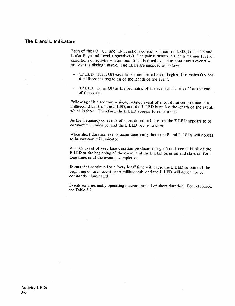
The E and L Indicators
Each of the DO, CL and CR functions consist of a pair of LEOs, labeled E andL (for Edge and Level, respectively). The pair is driven in such a manner that allconditions of activity -- from occasional isolated events to continuous events -are visually distinguishable. The LEOs are encoded as follows:
"E" LED. Turns ON each time a monitored event begins. It remains ON for6 milliseconds regardless of the length of the event.
- "L" LED. Turns ON at the beginning of the event and turns off at the endof the event.
Following this algorithm, a single isolated event of short duration produces a 6millisecond blink of the E LED, and the L LED is on for the length of the event,which is short. Therefore, the L LED appears to remain off.
As the frequency of events of short duration increases, the E LED appears to beconstantly illuminated, and the L LED begins to glow.
When short duration events occur constantly, both the E and L LEDs will appearto be constantly illuminated.
A single event of very long duration produces a single 6 millisecond blink of theE LED at the beginning of the event, and the L LED turns on and stays on for along time, until the event is completed.
Events that continue for a "very long" time will cause the E LED to blink at thebeginning of each event for 6 milliseconds, and the L LED will appear to beconstantly illuminated.
Events on a normally-operating network are all of short duration. For reference,see Table 3-2.
Activity LEOs3-6
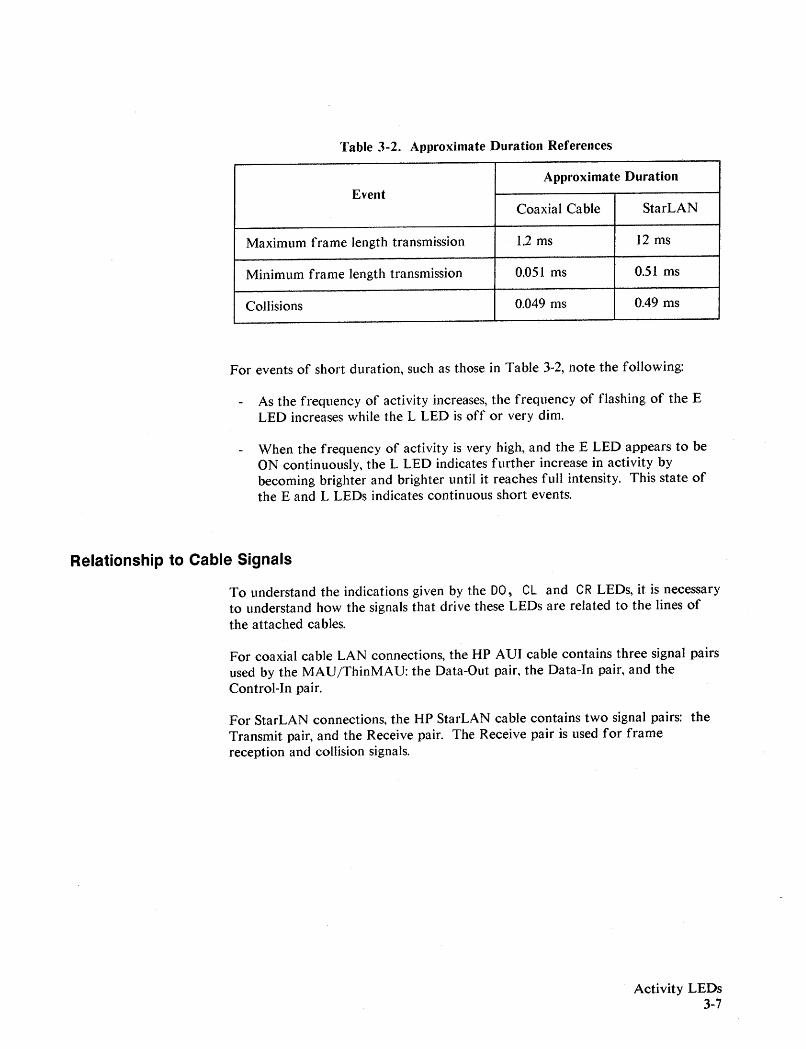
Table 3-2. AplJroximate Duration References
Approximate DurationEvent
Coaxial Cable StarLAN
Maximum frame length transmission 1.2 ms 12 ms
Minimum frame length transmission 0.051 ms 0.51 ms
Collisions 0.049 ms 0.49 ms
For events of short duration, such as those in Table 3-2, note the following:
As the frequency of activity increases, the frequency of flashing of the ELED increases while the L LED is off or very dim.
When the frequency of activity is very high, and the E LED appears to beON continuously, the L LED indicates further increase in activity bybecoming brighter and brighter until it reaches full intensity. This state ofthe E and L LEDs indicates continuous short events.
Relationship to Cable Signals
To understand the indicat.ions given by the DO, CL and CR LEDs, it. is necessaryto understand how the signals that drive these LEDs are related to the lines ofthe attached cables.
For coaxial cable LAN connections, the HP AVI cable contains three signal pairsused by the MAU/ThinMAV: the Data-Out pair, the Data-In pair, and theControl-In pair.
For StarLAN connections, the HP StarLAN cable contains two signal pairs: theTransmit pair, and the Receive pair. The Receive pair is used for framereception and collision signals.
Activity LEDs3-7
Activity LEDs3-8
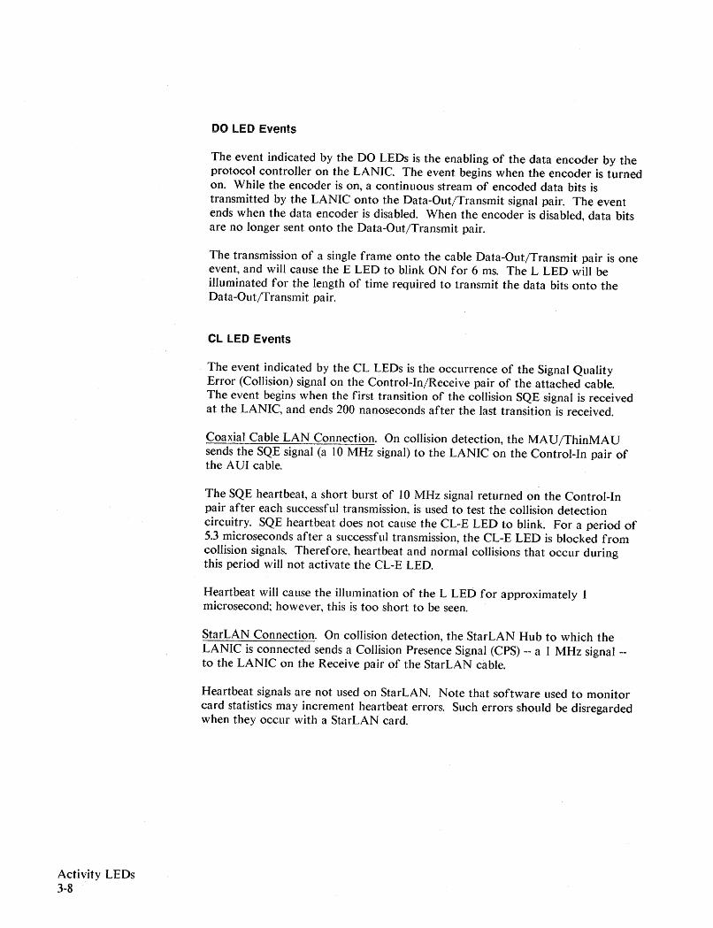
DO LED Events
The event indicated by the DO LEOs is the enabling of the data encoder by theprotocol controller on the LANIC. The event begins when the encoder is turnedon. While the encoder is on, a continuous stream of encoded data bits istransmitted by theLANIC onto the Data-Out/Transmit signal pair. The eventends when the data encoder is disabled. When the encoder is disabled, data bitsare no longer sent onto the Data-Out/Transmit pair.
The transmission of a single frame onto the cable Data-Out/Transmit pair is oneevent, and will cause the E LED to blink ON for 6 ms. The L LED will beilluminated for the length of time required to transmit the data bits onto theData-Out/Transmit pair.
CL LED Events
The event indicated by the CL LEOs is the occurrence of the Signal QualityError (Collision) signal on the Control-In/Receive pair of the attached cable.The event begins when the first transition of the collision SQE signal is receivedat the LANIC, and ends 200 nanoseconds after the last transition is received.
Coaxial Cable LAN Connection. On collision detection, the MAV /ThinMAUsends the SQE signal (a 10 MHz signal) to the LANIC on the Control-In pair ofthe AVI cable.
The SQE heartbeat, a short burst of 10 MHz signal returned on the Control-Inpair after each successful transmission, is used to test the collision detectioncircuitry. SQE heartbeat does not calise the CL-E LED to blink. For a period of5.3 microseconds after a successful transmission, the CL-E LED is blocked fromcollision signals. Therefore, heartbeat and normal collisions that occur duringthis period will not activate the CL-E LED.
Heartbeat will cause the illumination of the L LED for approximately 1microsecond; however, this is too short to be seen.
StarLAN Connection. On collision detection, the StarLAN Hub to which theLANIC is connected sends a Collision Presence Signal (CPS) -- a 1 MHz signal -to the LANIC on the Receive pair of the StarLAN cable.
Heartbeat signals are not used on StarLAN. Note that software used to monitorcard statistics may increment heartbeat errors. Such errors should be disregardedwhen they occur with a StarLAN card.
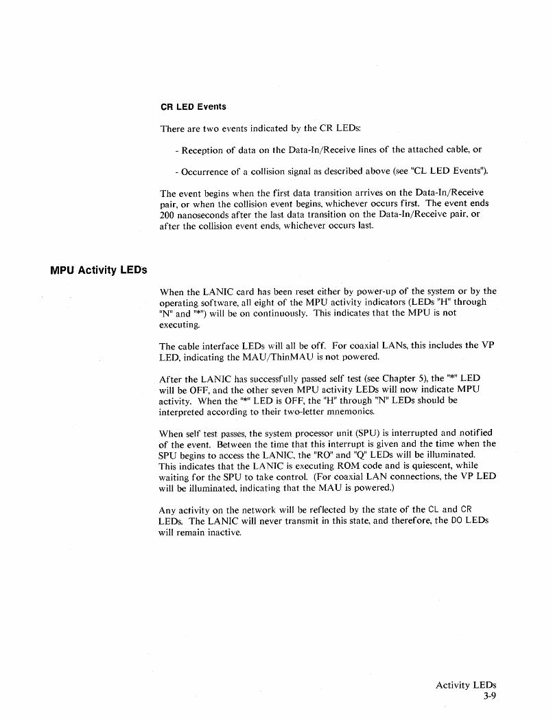
MPU Activity LEOs
CR LED Events
There are two events indicated by the CR LEOs:
- Reception of data on the Data-In/Receive lines of the attached cable, or
- Occurrence of a collision signal as described above (see "CL LED Events").
The event begins when the first data transition arrives on the Data-In/Receivepair, or when the collision event begins. whichever occurs first. The event ends200 nanoseconds after the last data transition on the Data-In/Receive pair, orafter the collision event ends, whichever occurs last.
When the LANIC card has been reset either by power-up of the system or by theoperating software, all eight of the MPU activity indicators (LEOs "H" through"N" and "*") will be on continuously. This indicates that the MPU is notexecuting.
The cable interface LEOs \\rill all be off. For coaxial LANs, this includes the VPLED, indicating the MAU/ThinMAU is not powered.
After the LANIC has successfully passed self test (see Chapter 5), the "*" LEDwill be OFF, and the other seven MPU activity LEOs will now indicate MPUactivity. When the "*" LED is OFF, the "H" through "N" LEOs should beinterpreted according to their two-letter mnemonics.
When self test passes, the system processor unit (SPU) is interrupted and notifiedof the event. Between the time that this interrupt is given and the time when theSPU begins to access the LANIC, the "RO" and "Q" LEOs will be illuminated.This indicates that the LANIC is executing ROM code and is quiescent, whilewaiting for the SPU to take control. (For coaxial LAN connections, the VP LEDwill be illuminated, indicating that the MAU is powered.)
Any activity on the network will be reflected by the state of the CL and CRLEOs. The LANIC will never transmit in this state, and therefore, the DO LEDswill remain inactive.
Activity LEDs3-9
Activity LEDs3-10
On command from operating software, the SPU prepares the LANIC foroperation. It must first download the operating firmware from system memoryto the LANIC. When this process begins, the "DL" LED turns ON, and the "Q"and "IT" LEDs will extinguish. After each download command, the "Q" LEDlights for a few miIIiseconds. At least 7 download commands occur, but theymay not be separately distinguishable. Note that the pattern that occurs on oneworking system will occur on all other working systems. So if you are suspiciousof this process on your system, compare the download pattern on the suspectsystem with a system that works.
After the download is complete, the SPU will instruct the MPU to begin toexecute the downloaded firmware. When this occurs, the "RO" and "DL" LEDswill extinguish. The "Q" and "IT" LEDs will turn ON.
A short time later the SPU will instruct the LANIC to set its individual node(station) address. When this occurs, the LANIC performs a duplicate addresscheck, which is accomplished by transmitting 10 self-addressed frames onto thenetwork with a 500 ms separation between frames. The "TX" and "DO-E" LEDswill both turn ON for each of the 10 frames. In addition, the "CR-E" LED willindicate that the frames were sent onto the coax and caused carrier to come on.If collisions occur, frame transmission will be retried up to 15 times each, withthe resultant activity indicated on the "CL" LEDs.
Because the frames are self-addressed, the "RX" LED should not light during theduplicate address check. If the "RX" LED does light, it is due to a framereceived from a remote node. This may occur, for example, if a duplicate stationexists, or an ordinary frame is addressed to the local LANIC.
If a reply to the duplicate address check is received, the duplicate address checkfails. No further check frames will be sent. The system software wiII close thelink and clear the LANJC, forcing all the LANIC card activity LEDs to turn ONand stay ON. The LEDs will indicate extended idle self test in progress.
If the duplicate address check passes, the link is opened, and frame transmissionand reception wiII commence. The LEDs will indicate activity as it occurs.
Presuming the network and LANIC card are idle prior to a transmit requestfrom the SPU to the LANIC card, frame transmission should behave as followsduring normal network operation:
While idle, "Q" and "IT" LEOs are ON. For coaxial LAN connections, the"VP" LED is ON.
When the MPU begins processing the transmit command, the "Q" and "IT"LEOs will extinguish, and the "TX" LED will light. The LANIC begins thetransmit process by reading the frame from system to on-card memory.
Once the frame is in LANIC card local memory, and the network is free, theserial transmission process begins. This causes the "DO-E" LED to light. The"DO-L" LED will also light for the duration of the frame transmission, butthis mayor may not be visible depending upon the length of the individualframe being sent.
For coaxial LAN connections, the serial data reaches the MAU/ThinMAUand is transmitted onto the coaxial cable. The MAUjThinMAU receives itsown signal off of the coax, and sends it back down the AUI cable on theData-In signal pair.
For StarLAN, the serial data is transmitted on the StarLAN cable. The Hubreceives the data and sends it down the Receive signal pair.
The LANIC card detects data arriving on the Data-In/Receive pair of theattached cable, resulting in the "CR-E" LED turning ON. The "CR-L" LEDwill also be illuminated for the duration of the frame, but this mayor maynot be visible. If the "DO-L" LED is visible, the "CR-L" LED will also bevisible for approximately the same length of time.
If no collision is encountered, the "CR-E" and "DO-E" LEOs will go OFFafter 6 milliseconds, followed quickly by the "TX" LED going OFF, and the"Q" and "IT" LEOs turning ON.
If a collision is encountered, the "CL-E" LED will turn ON, and up to 15additional attempts to transmit the frame will occur. From theretransmission attempts, the "DO" and "CR-E" LEOs may appear to be ON,and the "DO" and "CR-L" LEDs will probably appear to be partiallyilluminated. The intensity of the "-L" LEOs will be determined by framelength, the number of retransmissions, and the time separation of theretransmissions. The "CL" LEDs will also display behavior similar to the"CR" and "DO" LEOs if multiple retransmissions are required before theframe is successfully transmitted.
In the collision case, it must be remembered that other network activity mayalso cause the "CL" and "CR" LEDs to light, and the activity caused by theLANIC will be superimposed upon the network activity being displayed inthe "CR" and "CL" LEOs.
Activity LEOs3-11
Network Fault LED Examples
This section provides examples of LAN faults and the resulting display of aLANIC card's cable interface activity LEDs.
We presume that the LANIC card is enabled for operation on the network andthe LANIC card driver is turned on. This can be verified by the SHOWCOMcommand (see Chapter 2): the line must be "CONNECTED".
NOTE
The LANIC card LEOs will not reflect network activity if the line is notCONNECTED. For some faults, system software may shut down and reset the card,resulting in a DISCONNECTED line.
Due to hardware differences, coaxial cable connection faults differ fromStarLAN connection faults.
Coaxial Cable LAN
The following faults and cable interface activity LED displays pertain to coaxialcable LAN connections.
Open Tap
If the tap on the coax is not making contact with either the center conductor orshield, the LEOs will indicate no network activity.
When the LANIC tries to transmit, a coJIision will occur. Thus, the OO-E, CR-Eand CL-E LEOs will all light.
Activity LEOs3-12
Open Coax
Open coax faults include missing or loose terminators, loose barrel connectors, oreven breaks in the cable. For open coax faults, attempted transmission by anynode attached to the cable will result in a collision. For nontransmitting nodes,the CR-E and CL-E LEDs may light. For transmitting nodes, the DO-E, CR-Eand CL-E LEOs will light.
Note that, unlike an open tap fault where only the single node is affected, allHP 3000 nodes connected to the open coax cable will display these symptoms.
Shorted Coax
For a shorted coax, the voltage associated with any transmission attempt will beclamped to zero (loss of carrier). If the coax is shorted close to theMAUjThinMAU, the CR-E and DO-E LEDs will flash when the node attemptsto transmit.
Short On MAU/ThinMAU Power Circuit (VP)
If there is a short on the power lines going to the MAUjThinMAU, the LANICovercurrent protect switch will turn the power off, and the VP LED will turnOFF. If this occurs during the self test, a failure code, 24H, will result.
If the short occurs during normal operation of the board, card firmware willattempt to turn the power back on. This may occur up to 20 times. If this fails,the firmware will report a fatal error to the driver and enter a soft reset state inwhich the RO and Q LEDs will be lit. When the upper level software recognizesthe fatal error, it will do a hard reset on the card, leaving LEOs "H" through "*"lit.
Continuous 'Transmission From a Remote Node
If some other node is transmitting continuously, and its MAUjThinMAU fails toterminate its transmission, the local LANIC card will detect carrier. Thus, itsCR-L LED will be ON.
Constant Collision on the Network
Excessive voltages on .the coax are interpreted as collisions, for example, whenmultiple transmissions simultaneously exist on the cable, or a faultyMAU jThinMAU is leaking a DC voltage onto the coax. The localMAUjThinMAU detects such voltages and actuates the Control-IN (CI) signalline. This will cause the CL-L and CR-L LEDs to turn ON.
Activity LEDs3-13
Activity LEDs3-14
Open or Shorted Data Out Signal Lines
If the Oata Out signal pair in the AVI is open or shorted, the LANIC will not beable to transmit. Ouring transmit attempts, the OO-E LED will flash. However,since no transmission occurs, carrier will not be detected and the CR LEOs willnot turn on.
Note, however, that the LANIC will be able to receive frames. Received frameswill light the CR LEOs.
Open or Shorted 01 Pair in AUI
If the Data-In signal pair is disabled due to a short or a open, normal networkactivity will not be detected by the CR LEOs.
However, the CR LEOs are lit for collision signals on the Control-In signal pair,so a collision will cause the CR-E LEO along with the CL-E LED to blink ON.
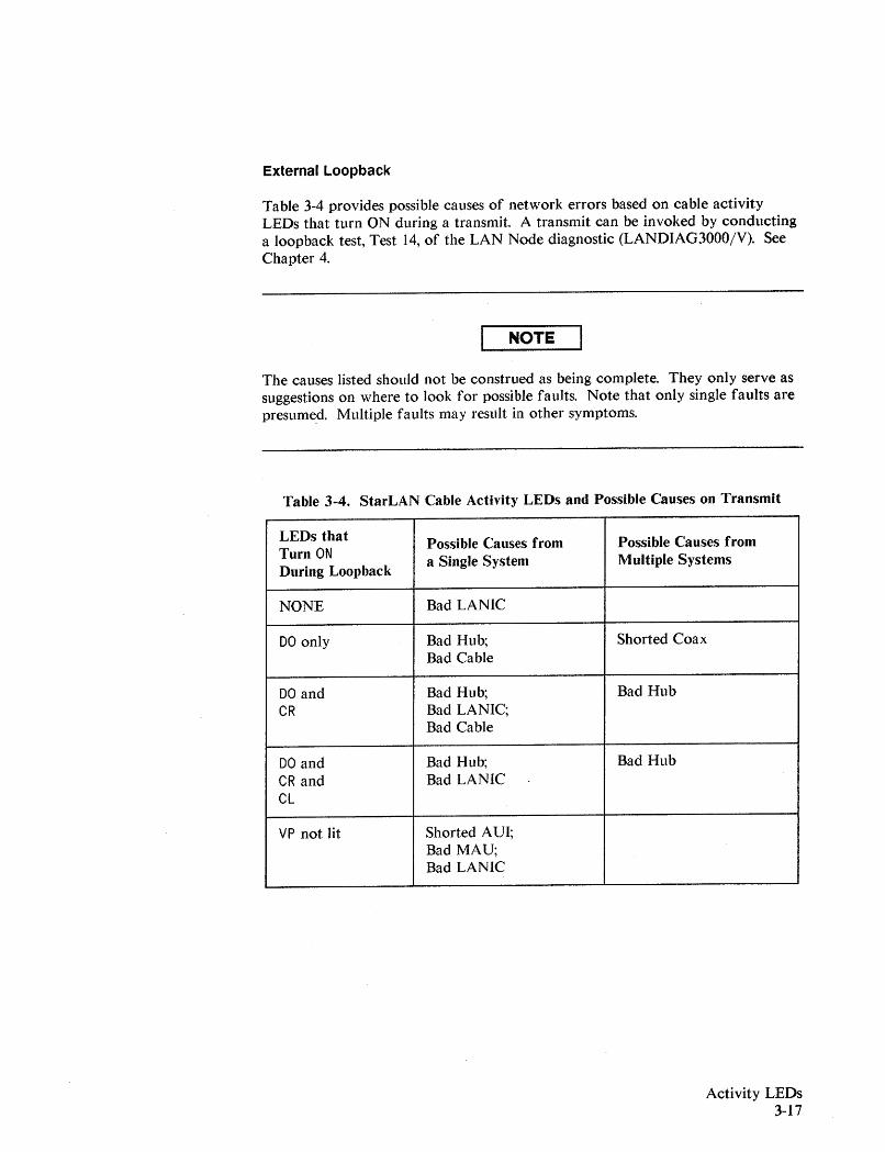
External Loopback
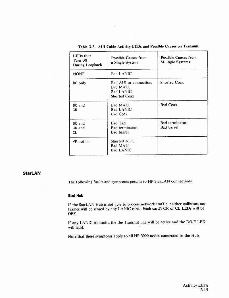
Table 3-3 provides possible causes of network errors based on cable activityLEOs that turn ON during a transmit. A transmit can be invoked by conductinga loopback test, Test 14, of the LAN Node diagnostic (LANDIAG3000/V). SeeChapter 4.
NOTE
The causes listed should not be construed as being complete. They only serve assuggestions on where to look for possible faults. Note that only single faults arepresumed. Multiple faults may result in other symptoms.
StarLAN
Table 3-3. AUI Cable ActiYity LEOs and Possible Causes on Transmit
LEDs thatPossible Causes from Possible Causes fromTurn ON
During Loopbacka Single System Multiple Systems
NONE Bad LANIC
DO only Bad AVI or connection; Shorted CoaxBad MAV;Bad LANIC;Shorted Coax
DO and Bad MAV; Bad CoaxCR Bad LANIC;
Bad Coax
DO and Bad Tap; Bad terminator;CR and Bad terminator; Bad barrel
·CL Bad barrel
VP not lit Shorted AVI;Bad MAV;Bad LANIC
The following faults and symptoms pertain to HP StarLAN connections.
Bad Hub
If the StarLAN Hub is not able to process network traffic, neither collisions norframes will be sensed by any LANIC card. Each card's CR or CL LEOs will beOFF.
If any LANIC transmits, the the Transmit line will be active and the OO-E LEOwill light.
Note that these symptoms apply to all HP 3000 nodes connected to the Hub.
Activity LEOs3-15
Activity LEDs3-16
Bad Connection
If the cable is not mated properly at each end, or the cable is severed, thesymptoms are the same as for a bad Hub, but apply only to the affected node.
Open or Shorted Transmit Pair
If the cable's transmit pair is open or shorted, the LANIC will not be able totransmit. Ouring transmit attempts, the OO·E LED will flash. However, since notransmission occurs, carrier will not be detected and the CR LEOs will not turnON for this attempted transmission.
Note, however, that the LANIC will be able to receive frames and detectcollisions. These events will light the CR and CL LEOs.
Open or Shorted Receive Pair
If the receive signal pair is disabled due to a short or open, normal networkactivity will not be detected by the CL or CR LEOs.
Continuous Transmission From a Remote Node
If some other node is transmitting continuously and its Hub fails to terminate itstransmission, the local LANIC card will detect carrier via the receive signal pair.Therefore, the CL-L and CR-L LEDs will turn ON.
Constant Collision on the Network
For StarLAN, the Hub generates collision signals and disseminates them on thereceive signal pair. If collision signals are constant, the the CL-L and CR-L LEOswill be ON.
External Loopback
Table 3-4 provides possible causes of network errors based on cable activityLEDs that turn ON during a transmit. A transmit can be invoked by conductinga loopback test, Test 14, of the LAN Node diagnostic (LANDIAG3000/V). SeeChapter 4.
NOTE
The causes listed should not be construed as being complete. They only serve assuggestions on where to look for possible faults. Note that only single faults arepresume.d. Multiple faults may reStilt in other symptoms.
Table 3-4. StarLAN Cable Activity LEDs and Possible Causes on Transmit
LEDs thatPossible Causes from Possible Causes from
Turn ONa Single System Multiple Systems
During Loopback
NONE Bad LANIC
DO only Bad Hub; Shorted CoaxBad Cable
DO and Bad Hub; Bad HubCR Bad LANIC;
Bad Cable
DO and Bad Hub; Bad HubCR and Bad LANICCL
VP not lit Shorted AVI;Bad MAV;Bad LANIC
Activity LEDs3-17

LAN Node Diagnostic
General Information
4
This chapter describes the LAN Node Diagnostic as a tool in troubleshooting anMPE-V system link.
What is the LAN Node Diagnostic?
The LAN Node Diagnostic, or LANDIAG, is an interactive online programdesigned to help identify malfunctioning LAN link hardware. The diagnosticperforms a series of tests upon the LANIC card and interface hardware. Eachtest diagnoses a subset of the node's link hardware. Although it can help toidentify a particular field replaceable unit (FRU), it may may not be able todistinguish which particular circuit within the FRU is malfunctioning.
As a program running on the HP3000, LANDIAG tests the connection betweenthe host computer and the main module of the LANIC card. The main moduleis that part of the LANIC card hardware which performs the network interfaceactivities.
LANDIAG can be used to initiate card self test. The LANIC self test checks thecomponents on the card for operation in the IEEE 802.3 environment. For moreinformation on LANIC card self test, see Chapter 5.
Required Hardware
LANDIAG is provided with the link products and HP network services(NS3000/V) software. When running this software, the system must have aminimum of two megabytes of memory and the Expanded System TableMicrocode. (Systems that are now memory-limited should add one megabyte tomaintain current performance.)
When using LANDIAG, one of the following LAN link products should beinstalled:
- ThinLAN3000/V or LAN3000/V links, for connecting HP 3000 Series3X/4X/5X/6X/7X and MICROJOOO systems to a ThinLAN or TbickLANcoaxial cable, respectively.
- StarLAN3000/V link, for connecting HP 3000 Series 37 or MICR03000systems to an HP StarLAN twisted pair cable.
LAN Node Diagnostic4-1
Required Software
Execution Time
LAN Node Diagnostic4-2
A maximum of one LAN hardware link per system is supported.
For general LANIC card installation guidelines, and interdependencies with otherI/O cards, refer to the LANIC installation manual provided with your particularlink product.
LANDIAG3000/V, version A.55.27.000, runs on HP 3000 or MICR03000 systemsexecuting the MPE V/E operating system, version V-B-delta-! (or later). Thisversion of LANDIAG incorporates changes required for the support of StarLANconnections. In addition, known bugs were corrected.
The diagnostic is provided on a master installation tape (MIT). It is providedalong with the LANIC card driver and NS3000/V.
The diagnostic is intended to be an online program, running on the MPE-Voperating system. It may be run timeshared with other programs, so that theLAN hardware may be inspected without disrupting the activities of users whodo not need to access the network.
NOTE
All network activity, including NS3000/V, must be halted before the diagnosticcan be executed.
'System Tables
LANDIAG is normally installed with NS3000/V and the driver. Beforeconfiguring and activating NS3000/V and the LAN link, you should check thesystem tables. Consult the "System Configuration" sections in the N S3000IVNetwork Manager Relerence Manual, 32344-90002, for guidelines on system tablemodifications required.
The diagnostic can execute one complete cycle of tests in under one minute.This is all the time needed to determine that the hardware is free from mostdefects. However, if there are intermittent or unusual problems, many passesthrough the diagnostic rnay be required.
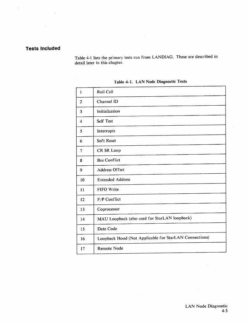
Tests Included
Table 4-1 lists the primary tests run from LANDIAG. These are described indetail later in this chapter.
Table 4-1. LAN Node Diagnostic Tests
1 Roll Call
2 ChannelID
3 Initialization
4 Self Test
5 Interrupts
6 Soft Reset
7 CR SR Loop
8 Bus Conflict
9 Address Offset
10 Extended Address
11 FIFO Write
12 F/P Conflict
13 Coprocessor
14 MAD Loopback (also used for StarLAN loopback)
15 Date Code
16 Loopback Hood (Not Applicable for StarLAN Connections)
17 Remote Node
LAN Node Diagnostic4-3
Diagnostic Limitations
The following conditions are not tested from LANDIAG:
1. Selftest toggle switch failure (does not apply to Series 37 and MICR03000LANIC cards).
2. Light emitting diode failure.
These are not tested by the diagnostic because they cannot be handledprogrammatically. It would be a simple matter to verify their operation byobservation after initiating self test.
3. Priority logic failure.
The diagnostic cannot explicitly control or implicitly predict the state of thepriority lines, so testing is not possible. However, failure recognition ispossible. If the priority logic does not work, one of the following will likelyresult:
- erratic LANIC card operation,- performance degradation, or- SIMB/IMB deadlock.
4. Powerfail warning holdoff of master handshake.
Testing this condition would require creating a powerfail condition in thehost, which is beyond the scope of this diagnostic.
5. SIMB/IMB parity errors.
To test the parity error detector circuit, it would be necessary to risk systemintegrity by deliberately introducing parity errors into memory.
The need to test the parity error detection circuit from LANDlAG was notfelt to be necessary. Such faults are not catastrophic to system or networkoperation. In addition, other cards on the system would eventually detect aparity error.
6. Faulty bank lines that address out of bounds memory.
Though this condition will not be tested explicitly, it would be apparent if itoccurred. For example, on the series 39, 4x or 6x systems, the 1MB wouldhang if out of bounds addressing occurred.
LAN Node Diagnostic4-4
7. Holdoff of reset until handshake ends.
For Series 39 through 70 systems, the LANIC is protected from data loss ifthe selftest switch is inadvertently pushed during a handshake. This featureis not tested because it requires direct manual intervention.. If theimplementation circuitry were to fail and go undetected, the functionalityof the LANIC card would not be significantly impaired.
LAN Node Diagnostic4-5
Guidelines for Setting Up and Using LANDIAG
This section contains information that you will need to know before usingLANDIAG.
System Information
When the HP 3000 is configured, it needs to be told everything about the LANICcard, including its LDEV number, DRT number, driver name, device type anddevice subtype. The following information should be provided:
- Driver name: IOLANO. PUB. SYS- Device type: 17- Device subtype: 9
The LDEV number and the DRT number depend on the particular systemconfiguration. Refer to the MPE V System Operation and ResourceManagement Reference M anllal (32033-90005) for system configuration details.
To use LANDIAG, you will need the LDEV number of your LANIC card. It isthe first item requested by the diagnostic. The diagnostic locates the LANICcard by entering the I/O configuration table at the specified LDEV. If the tableindicates that the LDEV is not device type 17 and subtype 9, the user is told:
That LDEV is not configured as a LANIC.
Capability Levels
Because the diagnostic has direct access to every location in memory, use of theprogram is controlled.
The user must have one of these three capabilities in order to run the diagnostic:
OP - system supervisor or operatorDI - diagnosticianSM - system manager
If the user's security level is not sufficient, the following error message will bedisplayed on the screen:
OP, DI or 8M capability needed to run diagnostic.
For LANDIAG Test 17 (Remote Node Test), a CS capability -- allowing access tothe Communications Subsystem -- is also required.
LAN Node Diagnostic4-6
System Type Check
For Series 30/33 systems, the diagnostic will continue to run, but the followingwarning is issued:
Diagnostic not designed for HP3000 /30 or/33.
Operation with Network Services
Refer to the N S3000IV Network Manager Relerence Manual (32344-90002) forsoftware configuration of network services on the system.
When a communication subsystem has control of the LANIC card, any attemptto allocate it by the diagnostic will fail. The diagnostic will report a warning.The message will be:
The LANIC could not be allocated.
To use the diagnostic,the LANIC card must be in an "AVAILABLE" state. Youcan tell if the card is "AVAILABLE" as follows:
- From MPE, issue the SHO\VDEV command. The LDEVs will be listedalong with availability information. Locate theLDEV of the LANIC card;the status must indicate "AVAILABLE".
- From MPE, issue the SHOWCOM command, specifying the LDEV of theLANIC card (see Chapter 2). The card is available if the LINE isDISCONNECTED or CLOSED.
With the NS3000/V services installed, the command sequence:
:NSCONTROL STOP:NETCONTROL STOP
will disconnect the user's node from the network. For more information on theuse of these commands, refer to the NSI3000 Network Nfanager RelerenceM anlfal (32344-90002).
The user may run the diagnostic when the communication subsystems havereleased the LANIC card. The system can recover control of the LANIC if thereshould be a crash while the diagnostic is running.
LAN Node Diagnostic4-7
Reliability and Recovery from Power Failure
In the event of a power failure MPE-VIE will protect the integrity of the systemtables. For the Series 6x/70 systems, the diagnostic process will resume operation;no reinitialization will be necessary. For the Series 4xl5x systems, you have torestart the diagnostic.
The test which was underway when the power failure occurred will probablyreport a failure, whether or not the circuit being checked was actually faulty.This mistake will arise because the diagnostic will almost certainly timeoutwaiting for a response from the LANIC. This is because the LANIC (whichderives its power from the backplane) will lose the execution context as itsmicroprocessor and RAM will lose power due to power failure. Also, theLANIC performs a self test at power on, including a memory test whichobliterates the contents of local RAM.
When a power failure has taken place, you should redo any test that failed.
Integrity of the System
The diagnostic will expose any defect in the LANIC card which compromisessystem integrity. If the LANIC card contains such defects, there is anunavoidable risk of altering memory or system crashes. Because the diagnosticperforms rigorous testing of all LANIC circuits, including those that implementdirect memory access, intermittent problems will be exposed.
The diagnostic will not cause any crashes or damage to system memory whengood LANIC cards are tested. The diagnostic is no more likely to cause systemproblems than normal use of the LANIC by the LAN link and NS3000/Vproducts.
When a LANIC is installed or replaced, the diagnostic should be executed andsystem integrity verified before user processes are permitted to execute. Ifsystem failures are observed during normal operation and the LANIC issuspected to be the cause of the failures, users should be removed from thesystem prior to diagnostic execution.
If a LANIC card malfunction is suspected, but LANIC usage does not appear tohave compromised subsystem integrity, it is unlikely that diagnostic executionwill cause system integrity to be compromised. In this case the diagnostic can beexecuted without removing the users from the system.
Each time LANDIAG is run, it enforces conditional execution of its tests inorder to significantly reduce the probability of system halts. Table 4-2 showsvarious test completion states and their impact on other tests. (Note thatintermittent failures on the LANIC card may defeat the protection provided.)
LAN Node Diagnostic4-8
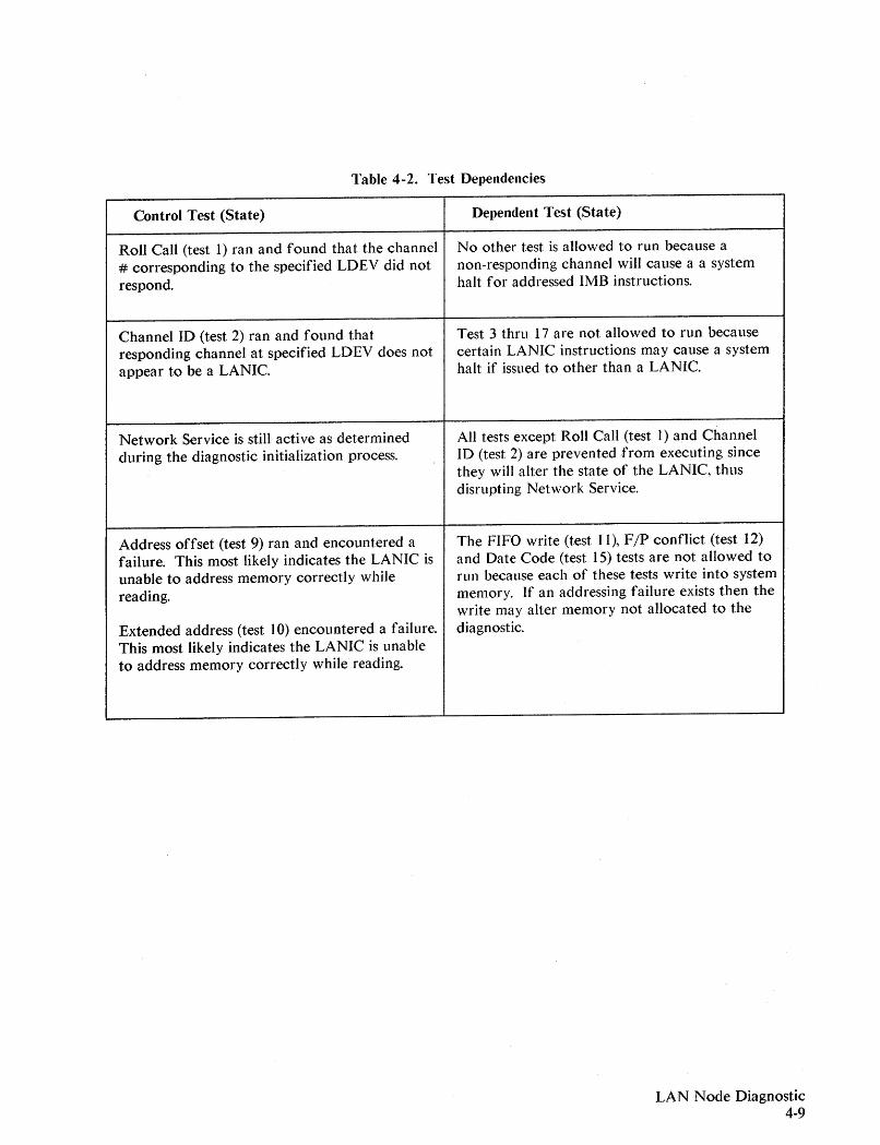
Table 4-2. Test Dependencies
Control Test (State) Dependent Test (State)
Roll Call (test 1) ran and found that the channel No other test is allowed to run because a# corresponding to the specified LDEV did not non-responding channel will cause a a systemrespond. halt for addressed 1MB instructions.
Channel ID (test 2) ran and found that Test 3 thru 17 are not allowed to run becauseresponding channel at specified LDEV does not certain LANIC instructions may cause a systemappear to be a LANIC. halt if issued to other than a LANIC.
Network Service is still active as determined All tests except Roll Call (test 1) and Channelduring the diagnostic initialization process. 10 (test 2) are prevented from executing since
they will alter the state of the LANIC, thusdisrupting Network Service.
Address offset (test 9) ran and encountered a The FIFO write (test 11), F jP conflict (test 12)failure. This most likely indicates the LANIC is and Date Code (test 15) tests are not allowed tounable to address memory correctly while run because each of these tests write into systemreading. memory. If an addressing failure exists then the
write may alter memory not allocated to theExtended address (test 10) encountered a failure. diagnostic.This most likely indicates the LANIC is unableto address memory correctly while reading.
LAN Node Diagnostic4-9
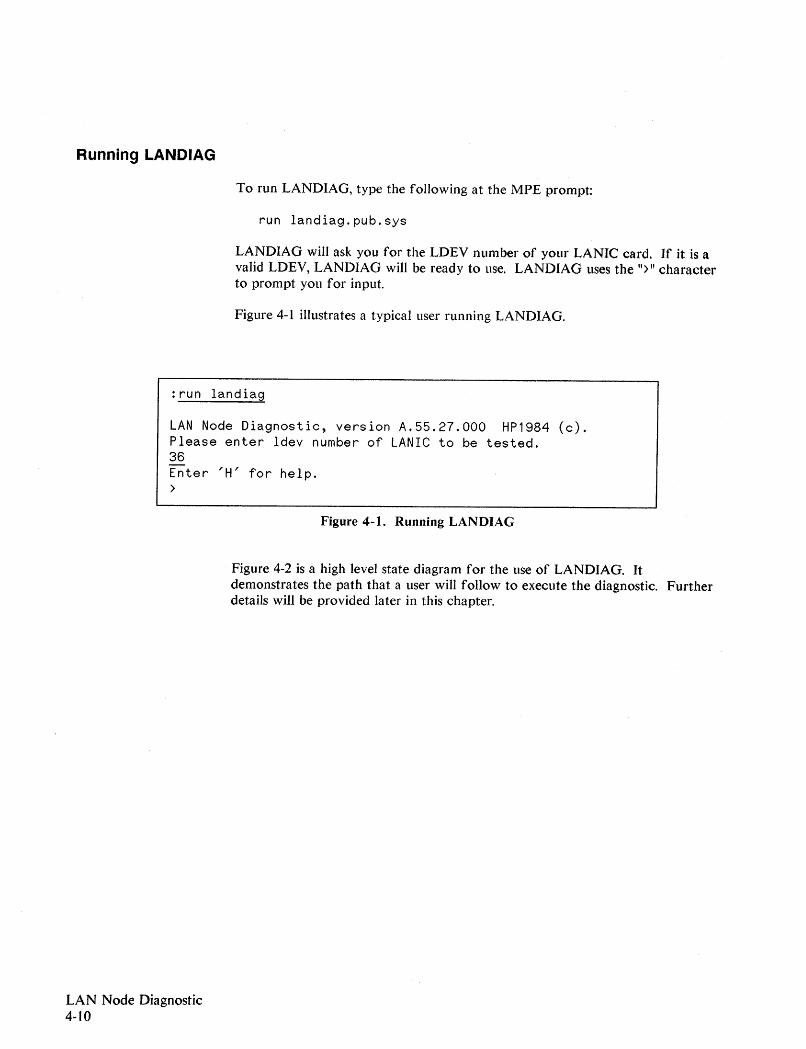
Running LANDIAG
To run LANDIAG, type the following at the MPE prompt:
run landiag.pub.sys
LANDIAG will ask you for the LDEY number of your LANIC card. If it is avalid LDEY, LANDIAG will be ready to use. LANDIAG uses the ">" characterto prompt you for input.
Figure 4-1 illustrates a typical user running LANDIAG.
:run landiag
LAN Node Diagnostic, version A.55.27.000 HP1984 (c).Please enter ldev number of LANIC to be tested.36Enter 'H' for help.>
Figure 4-1. Running LANDIAG
Figure 4-2 is a high level state diagram for the use of LANDIAG. Itdemonstrates the path that a user will follow to execute the diagnostic. Furtherdetails will be provided later in this chapter.
LAN Node Diagnostic4-10
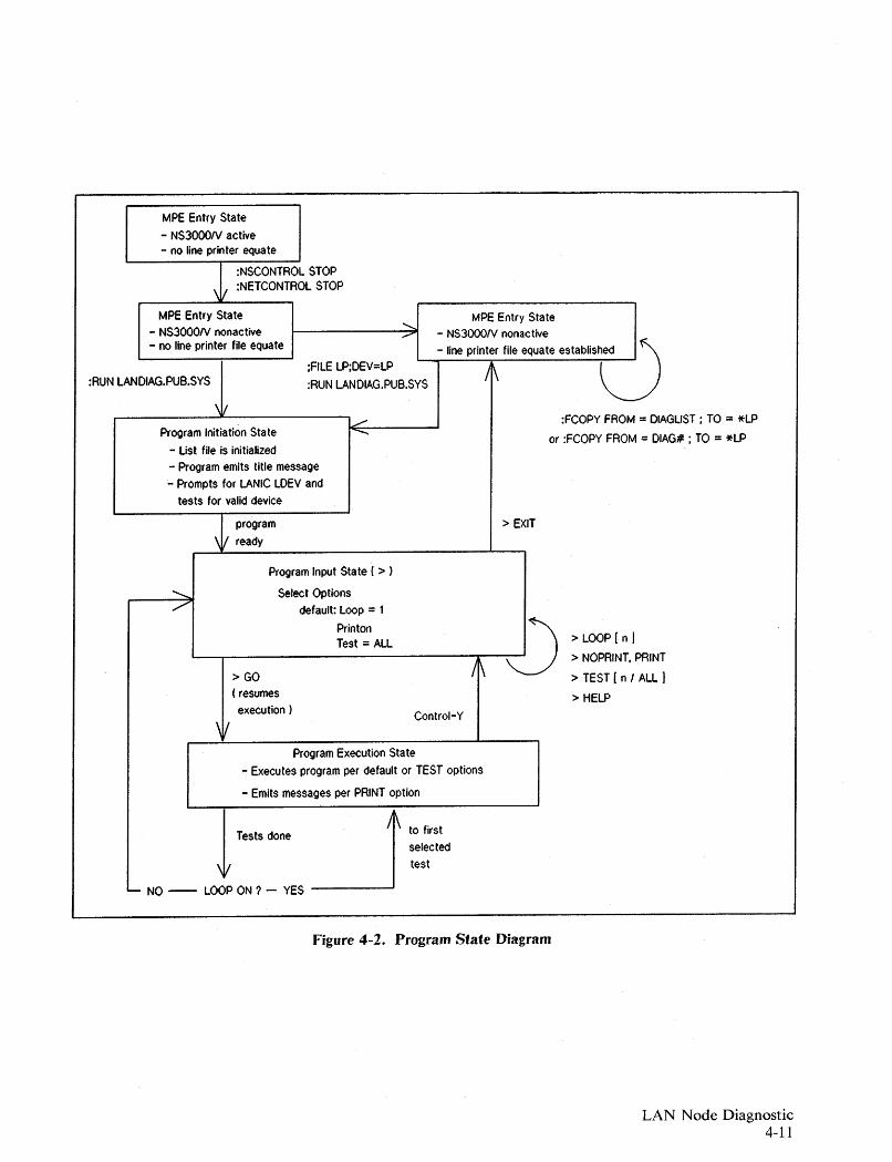
MPE Entry State
- NS3000N active- no line printer equate
:NSCONTROL STOP:NETCONTROL STOP
:FCOPY FROM = DIAGLIST ; TO = *LP
or :FCOPV FROM = DIAG# ; TO = *LP
MPE Entry State 1- NS3000N nonactive C)- line printer file equate established
/1\;FILE LP;DEV=LP
:RUN LANDIAG.PUB.SVS
MPE Entry State- NS3000N nonactive- no line printer file equate
\11_------:L.--------,~
Program Initiation State "".........;..------'
- Ust file is initialized- Program emits title message- Prompts for LANIC LDEV and
tests for valid device
:RUN LANDIAG.PUB.SVS
programready
> EXIT
> LOOP (n I> NOPRINT. PRINT
> TEST ( n I ALL )
> HELPControl-V
\1/
Program Input Sta te ( > )
........... Select Options/ default: Loop = 1
Printon l)Test = ALL
L-.....---------/'rl\-
>GO( resumesexecution)
Program Execution State- Executes program per default or TEST options
- Emits messages per PRINT option
1Tests done~ to firstselectedtest
L- NO -- LOOP ON ? - YES
Figure 4-2. Program State Diagram
LAN Node Diagnostic4-11
User Interface
Activity Indicator
LAN Node Diagnostic4-12
The diagnostic is an interactive program. The user determines the type ofoperation, performs a diagnosis, and is permitted to change the operatingcondition and test again, as many times as desired. The diagnostic is divided intothree sections:
- Initialization, in which setup takes place, transparently to the user, exceptfor being asked LDEV number and getting initialization error messages ifthey occur.
- Command entry, in which the user specifies the type of diagnosticoperation.
- Test execution, in which the hardware is inspected, faults are detected, andthe results are output.
After test execution is complete, or the user aborts test execution with a[CONTROLIY, the program will return to the command entry mode. Subsequently,the user may change the type of operation and test again, or exit fromLANDIAG to MPE.
The LAN Node Diagnostic can be used in either of two ways, Active mode orStandard mode:
- Standard mode: a predetermined sequence of tests is run; the user is notable to specify which tests to run. (Refer to the GO command, later in thischapter.)
- Active mode: tests are user specified. (Refer to the TEST command, later inthis chapter.)
LANDIAG time requirements for test completion depend on the test(s) run. Iftests are repeated (LOOP command), completion time is extended. To providestatus of test progress, the diagnostic provides activity indicators. Before any testis begun, the number of the test is displayed on the screen. As each step withinthe test is begun, an asterisk (*) is displayed on the screen.
If the system hangs, the user can determine which test and step was running justprior to the hang. This information may prove usefuJ for identifying andcorrecting a problem. After the last step in a test is completed, the message
end of pa~s
is displayed.
How to Get Output From LANDIAG
While all prompts, echoes, activity indicators and other useful information willbe sent to the user's screen, a summary of diagnostic results will be directed toboth the screen and the file known as DIAGLIST, if the diagnostic was invokedwith: RUN LANDIAG.
The file can also be named DIAG# where #=LDEV# if the diagnostic is invokedwith:
:RUN LANDIAG;parm=LDEV~
For example, if : RUN LANDIAG; parm=36 is used, diagnostic results are directedto a file DIAG36.
The user will not be able to use a file equation to associate the diagnostic outputfile with another file or device. In order to obtain hard copy of the diagnosticactivity, the user should direct the diagnostic output to a printer after the processis complete.
The command sequence is as follows:
:FILE LP;DEV=LP:FCOPY FROM =DIAGLIST;TO=*LP ,or:FCOPY FROM =DIAG#;TO=*LP
NOTE
DIAGLIST (or DIAG#) is reinitialized every time LANDIAG is invoked, henceresults from a previous diagnostic pass are lost. The user may save the results byeither printing a hardcopy as shown above or renaming the previous diagnosticlist file as follows:
:RENAME DIAGLIST, filename ,or:RENAME DIAG#, filename
Where #=LDEV number of LANIC being tested.
LAN Node Diagnostic4-13

Station (Link-Level) Addresses
Each node on the LAN is identified at the link level by a unique station address.The station address is a 12 digit hexadecimal number stored on the LANIC cardin ROM. It is normally labeled on the card, and documented on the networkmap. (Do not confuse the station address with the IP address of the node. TheIP address is an upper layer address for connecting processes.)
For some tests, specifically the -Remote Node Test, the station address of variousnodes may be needed. For HP 3000 systems, the station address can be obtainedthrough LANDIAG. However, you must be on the system to get the stationaddress of the LANIC card installed in that system.
If tests 1, 2, and 13 of LANDIAG have been successfully run, the station addresswill be displayed at the bottom of the screen resulting from the HELP command.The HELP command is described later in this chapter.
LAN Node Diagnostic4-14
Command Set
Seven commands are available to the user: EXIT, GO, HELP, LOOP, PRINT,NOPRI NT and TEST. Single letter abbreviations wiJ) be accepted and both uppercase and lower case letters will be understood. There is another input the usercan give, the [CONTROL)Y, which returns control from test execution back to thecommand entry mode.
NOTE
During the execution of most LANDIAG tests, response to a [CONTROLlY may bedelayed until after execution of a test step.
Due to programmatic protection, aborting a Remote Node Test (LANDIAG Test17) may require multiple [CONTROL)Y entries (i.e., you may be required to enter[CONTROLiY several times). The test will normally abort with [CONTROLIY after it hasreceived a loopback response frame, or after ithas timed out waiting for aresponse frame.
During the command entry phase of the program, the user may issue instructionsto control the operation of the diagnostic. Whenever a ">" prompt is provided, acommand is expected. If the command set is used incorrectly, a error message tohelp the user will be given. Refer to the "Error Messages" section at the end ofthis chapter.
The diagnostic is designed with default settings for all parameters except theLDEV to be tested. In most cases, use of commands other than TEST, GO, andEXI T will be rarely needed.
The tests are designed to be executed in sequence. Each time LANDIAG is run,test dependencies are enforced to ensure system integrity. See Table 4-3.
LAN Node Diagnostic4-15
LAN Node Diagnostic4-16
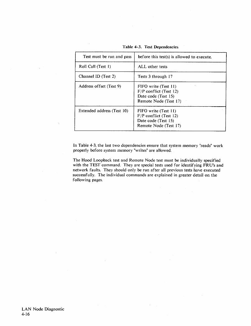
Table 4-3. Test Dependencies
Test must be run and pass before this testes) is allowed to execute.
Roll Call (Test 1) ALL other tests
Channel ID (Test 2) Tests 3 through 17
Address offset (Test 9) FIFO write (Test 11)F/P conflict (Test 12)Date code (Test 15)Remote Node (Test 17)
Extended address (Test 10) FIFO write (Test 11)F/P conflict (Test 12)Date code (Test 15)Remote Node (Test 17)
In Table 4-3, the last two dependencies ensure that system memory "reads" workproperly before system memory "writes" are allowed.
The Hood Loopback test and Remote Node test must be individually specifiedwith the TEST command. They are special tests used for identifying FRU's andnetwork faults. They should only be run after all previous tests have executedsuccessfully. The individual commands are explained in greater detail on thefollowing pages.
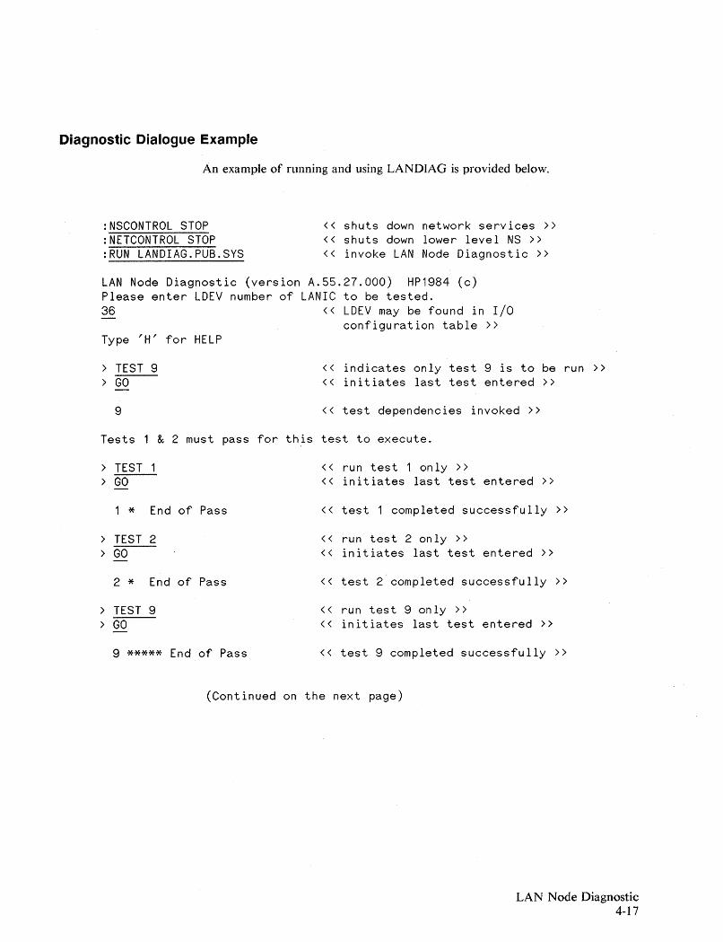
Diagnostic Dialogue Example
An example of running and using LANDlAG is provided below.
:NSCONTROL STOP:NETCONTROL STOP:RUN LANDIAG.PUB.SYS
« shuts down network services »« shuts down lower level NS »« invoke LAN Node Diagnostic »
LAN Node Diagnostic (version A.55.27.000) HP1984 (c)Please enter LDEV number of LANIC to be tested.36 « LDEV may be found in I/O
configuration table »Type 'H' for HELP
> TEST 9> GO
9
« indicates only test 9 is to be run »« initiates last test entered »
« test dependencies invoked »
Tests 1 & 2 must pass for this test to execute.
> TEST « run test 1 only »> GO « initiates last test entered »
1 * End of Pass « test 1 completed successfully »
> TEST 2 « run test 2 only »> GO « initiates last test entered »
2 * End of Pass « test 2 completed successfully »
> TEST 9 « run test 9 only »> GO « initiates last test entered »
9 ***** End of Pass « test 9 completed successfully »
(Continued on the next page)
LAN Node Diagnostic4-17
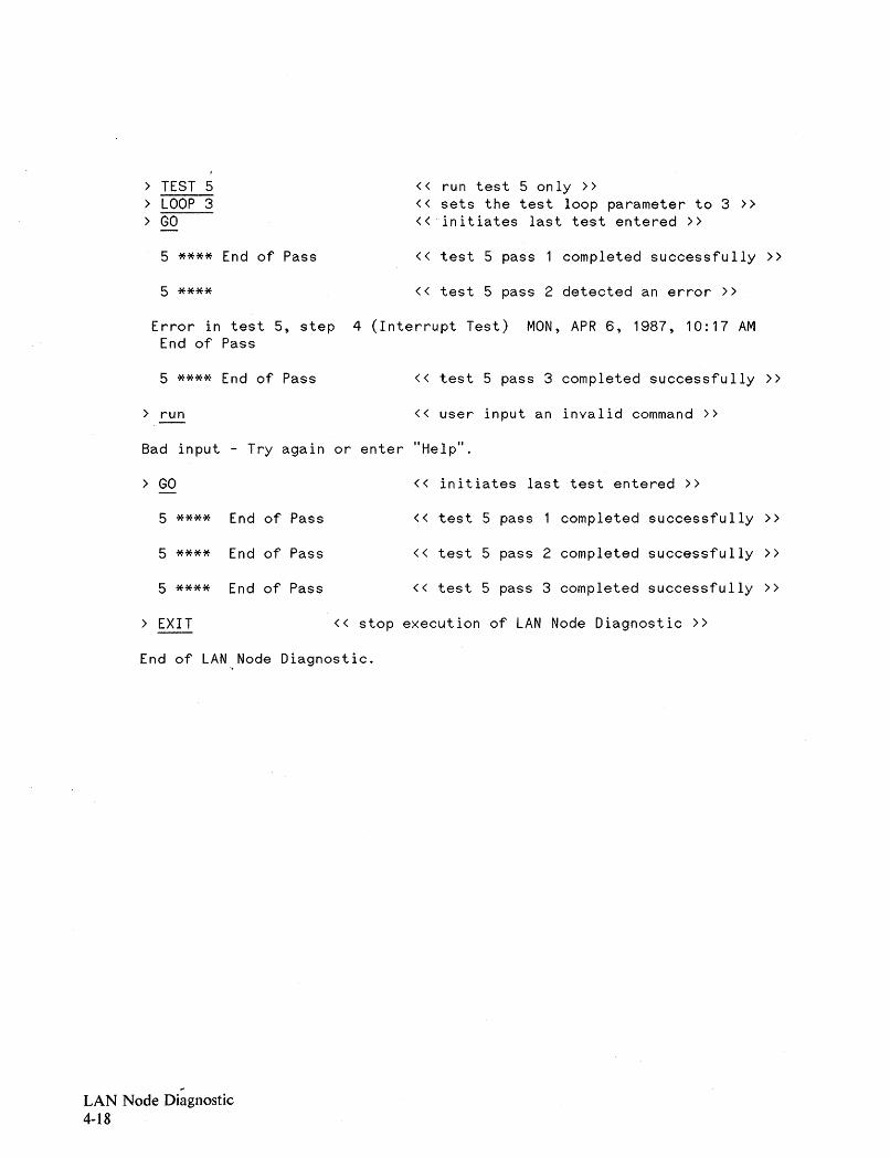
> TEST 5 « run test 5 only»> LOOP 3 « sets the test loop parameter to 3 »> GO « ·initiates last test entered »
5 **** End of Pass « test 5 pass completed successfully »
5 **** « test 5 pass 2 detected an error »
Error in test 5, step 4 (Interrupt Test) MON, APR 6, 1987, 10:17 AMEnd of Pass
5 **** End of Pass « test 5 pass 3 completed successfully »
> run « user input an invalid command »
Bad input - Try again or enter "Help "
> GO « initiates last test entered »
5 **** End of Pass « test 5 pass completed successfully »
5 **** End of Pass « test 5 pass 2 completed successfully »
5 **** End of Pass « test 5 pass 3 completed successfully »
> EXIT « stop execution of LAN Node Diagnostic »
End of LAN Node Diagnostic.~
...LAN Node Diagnostic4-18
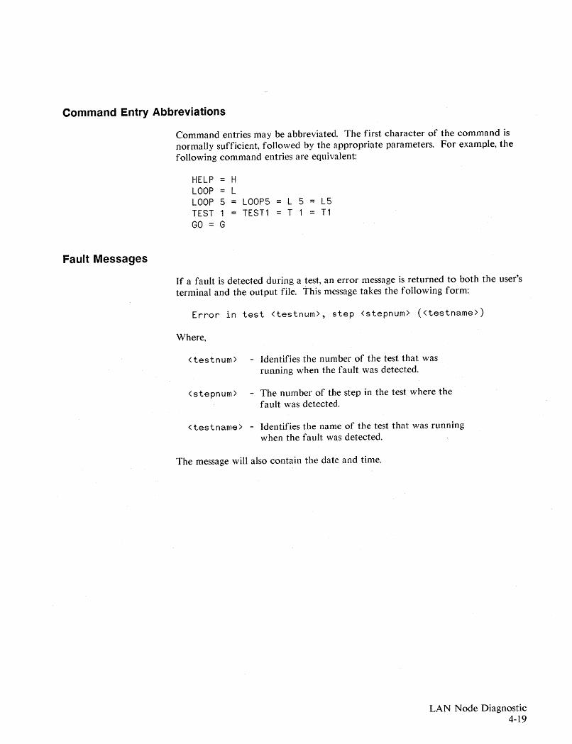
Command Entry Abbreviations
Command entries may be abbreviated. The first character of the command isnormally sufficient, followed by the appropriate parameters. For example, thefollowing command entries are equivalent:
HELP = HLOOP LLOOP 5 = LOOP5 = L 5 = L5TEST 1 = TEST1 = T 1 = T1GO = G
Fault Messages
If a fault is detected during a test, an error message is returned to both the user'sterminal and the output file. This message takes the following form:
Error in test <testnum>, step <stepnum> «testname»
Where,
<testnum> - Identifies the number of the test that wasrunning when the fault was detected.
<stepnum> - The number of the step in the test where thefault was detected.
<testname> - Identifies the name of the test that was runningwhen the fault was detected.
The message will also contain the date and time.
LAN Node Diagnostic4-19
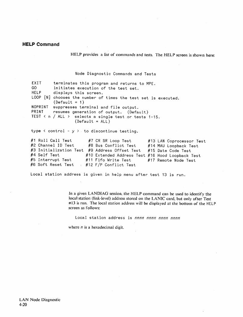
HELP Command
HELP provides a list of commands and tests. The HELP screen is shown here:
Node Diagnostic Commands and Tests
EXITGOHELPLOOP [N]
NOPRINTPRINTTEST < n
terminates this program and returns to MPE.initiates execution of the test set.displays this screen.chooses the number of times the test set is executed.(Default = 1)suppresses terminal and file output.resumes generation of output. (Default)/ ALL> selects a single test .or tests 1-15.
(Default = ALL)
type < control - y > to discontinue testing.
#1 Roll Call Test#2 Channel 10 Test#3 Initialization Test#4 Self Test#5 Interrupt Test#6 Soft Reset Test
#7 CR SR Loop Test#8 Bus Conflict Test#9 Address Offset Test
#10 Extended Address Test#11 Fifo Write Test#12 F/P Conflict Test
#13 LAN Coprocessor Test#14 MAU Loopback Test#15 Date Code Test#16 Hood Loopback Test#17 Remote Node Test
Local station address is given in help menu after test 13 is run.
In a given LANDIAG session, the HELP command can be used to identify thelocal station (link-level) address stored on the LANIC card, but only after Test#13 is run. The local station address will be displayed at the bottom of the HELPscreen as follows:
Local station address is nnnn nnnn nnnn nnnn
where n is a hexadecimal digit.
LAN Node Diagnostic4-20
EXIT Command
GO Command
LOOP Command
EX I T terminates the diagnostic and returns to MPE.
Execution of the EX I T command is the only way to return control to MPE.When the user stops the test execution with the [CONTROLlY character, thediagnostic will not terminate. It merely returns to the command mode.
GO begins or continues execution of tests. The tests that are performed when theGO command is entered are determined by the test selected with the latestTEST <n/a 11> command. The number of times the test is looped is set by theLOOP command. If neither command was given, GO will cause the initiation ofone pass of the complete test set (Test 1-15).
Once testing has begun, testing may be stopped before completion of the selectedtest (with the specified number of loops) by entering a [CONTROLlY character. Thiswill return the user to the command entry mode, identified by the> prompt.After a [CONTROL)Y, a subsequent GO command will simply restart the same test.
The LOOP command establishes the number of times that a test, specified by theTEST command, is continuously run. Using this command, a test may be run anumber of times without repeated command entry.
If LOOP is not specified during a LANDIAG session, its value defaults to "1". Thenumber of times a test is repeated is determined by the parameter N followingthe LOOP command. This is illustrated as follows:
> LOOP 5> LOOP 1> LOOP
N = 5, the test will be run 5 times.N = 1, the test will be run once.N =0, the test will be run continuously.
The LOOP command is used primarily to find intermittent problems, or to studythe link hardware with an oscilloscope. It is recommended that oscilloscopeloops be performed with "print off" (see the NOPRINT command).
Once testing has begun, the only way to terminate execution before N iterationsof the test is with [CONTROL)Y. This will return the user to the command entrymode, identified by the ">" prompt.
LAN Node Diagnostic4-21
NOPRINT Command
NOPRI NT suppresses terminal and file output. It is useful during loop tests withan oscilloscope since it eliminates overhead associated with such output andincreases the speed by which an iteration is made.
PRINT Command
PRIN T resumes generation of terminal and file output, which is the default state.The filename being logged to depends on the way in which you invoked thediagnostic.
If PARM is used in theLANDIAG run string to specifythe card's LDEV, then thelog file name is DI AG#, where #=PARM=L DEV. This is illustrated below:
: RUN LANDIAG. PUB. SYS; PARM=LDEV
If PARM is not used, then the log file is DIAGLIST.
Note that DIAG# or DIAGLIST will be in the group.account from which youinvoked LANDIAG.
TEST NIALL Command
The TEST command is used to select the LANDIAG test to be run. The desiredtest is specified by a parameter, N, in the command run string. Note thefollowing:
TESTTEST 0TEST 1TEST 2
TEST 15TEST ALLTEST 16TEST 17
N = default (see "N = ALL", below)N = default (see "N = ALL", below)N = I, Test I is run.N = 2, Test 2 is run.
N = 15, Test 15 is run.N = ALL, Tests 1 through 15 are run.N = 16, Test 16 is run (coax LANs only).N= 17, Test 17 is run.
There are a couple of noteworthy points:
• If N is "0" or not specified, the default is ALL.
• Tests 16 or 17 can be executed only with the commands TEST 16 orTEST 17, respectively, followed by the GO command.
LAN Node Diagnostic4-22
Test Descriptions
LANDIAG provides a number of Tests, each consisting of multiple Steps.
A Test is a sequence of interactions between the host system and and the LANICcard designed to verify the correctness of data and control paths.
A Step is a single interaction between the host and the LANIC intended to gathersome information about a particular data or control path, contributing to theevaluation of that path.
Each test will begin with a reset of the LANIC card, to bring it into a knownstate. In some of the tests, the next step will be to download a small piece ofZ80 software. This code will prepare the LANIC cardto perform subsequentsteps.
This section describes each LANDIAG test.
LAN Node Diagnostic4-23

Test #1. Roll Call Test
The roll call test verifies that the channel specified by the user, via the LDEV,responds to the IMB\SIMB roll call instruction. The diagnostic requires the userto run this test prior to other tests since a nonresponding channel will cause asystem halt. If this test fails, all subsequent tests are not allowed to fun.
Possible causes of failure include:
- The system I/O table does not match the hardware configuration.
- The I/O configuration table has been corrupted.
- The LANIC card is faulty.
If Test #1 fails, you should acquire a listing of the system I/O configuration (mayuse SYSDUMP $NULL ,$STDLIST) and verify that the mapping of LDEVs,DRT#s, and thumbwheel settings of all I/O channels are consistent. For help,refer to HP 3000 Computer Systems, MPE V System Operation and ResourceManagement Reference M anllal (32033-90005).
Correct any discrepancies found between the hardware channel settings and thesystem I/O configuration table. If there are no discrepancies, try replacing theLANIC card.
NOTE
The success of this test does not prove that there is a LANIC card at the correctchannel number, only that there is a channel present. The next test verifies thatthe channel is a LANIC card.
LAN Node Diagnostic4-24
Test #2. Channel 10 Test
Test #2 verifies that the channel specified by the user, via the LDEV, is indeed aLANIC card. First, a check is made on the results of the Roll Call test (Test #1).If a responding channel is not present at the specified LDEV, Test #2 is notallowed to run. Next, register 14 (configuration register) of the specified channelis read and compared to a special ID code assigned to the LANIC card. If thechannel responds· with the correct ID code, the test passes.
If Test #2 test fails, a flag is set that prevents all subsequent tests from running.This prevents the possibility of system halts.
Possible causes of test failure include:
- The channel specified by the LDEV is not a LANIC card. This assumesthat the system has been configured correctly.
- There are non-LANIC card channels with the same channel number as theLANIC card being tested (i.e., thumbwheel switches set to the samenumber).
- The system I/O table does not match the hardware configuration.
- The I/O configuration table has been corrupted.
- The LANIC card is faulty.
If Test #2 fails, you should acquire a liStitlg of the system I/O configuration (mayuse: SYSDUMP $nu 11, $std 1ist). Verify that the mapping of LDEVs andDRT#s and thumbwheel settings of all I/O channels are correct.
If there are discrepancies between the hardware channel settings and the systemI/O configuration table, correct them. If there are no discrepancies, try replacingthe LANIC card.
LAN Node Diagnostic4-25
Test #3. Initialization Test
Test #3 determines if the LANIC responds to the IMB/SIMB INIT instruction byhalting the 280 and clearing the CRFULL bit (an indication that an internal resetpulseis generated). There are 3 steps to this test:
Step 1: The Z80 is launched into a self test to ensure that it is not initially in ahalted state. A write to the control register is then performed to setthe CRFULL bit. Subsequently, the CRFULL bit is checked; if it is notset, Step 1 fails.
A Step 1 failure most likely indicates a LANIC failure. Replace theLANIC.
Step 2: An INIT is issued to the LANIC card. This should halt the Z80 andclear the CRFULL bit. Subsequently, the CRFULL bit is checked; if itis not cleared, Step 2 fails.
A failure in Step 2 most likely indicates a LANIC card failure. Replacethe LANIC.
Step 3: This step verifies that the 280 was actually halted by the INIT in Step2. Another write to the Control register is performed to set theCRFULL bit. The diagnostic then pauses for 5 seconds; if the Z80 wasnot halted by Step 2, the CRFULL bit will be cleared. Subsequently,the CRFULL bit is checked; if it has been cleared, Step 3 fails.
A failure in step 3 most likely indicates a LANIC card fault. Replacethe LANIC card.
LAN Node Diagnostic4-26
Test #4. Self Test
Test #4 programmatically initiates the LANIC card selftest program contained inROM on the card. The self test is a comprehensive verification of the LANICmain module, that is, all circuitry not associated with the IMB/SIMB interface.Refer to Chapter 5 for selftest LEOs and failure codes.
There are three steps to this test:
Step 1: This step issues an INIT to the LANIC card, then writes to the controlregister the code indicating that a full self test is to be fun. Then itreads the status of the CRFULL bit, which should be set toacknowledge the control register write. If the CRFULL bit is not set,this step fails.
A Step 1 failure most likely indicates a LANIC card fault. Replace theLANIC card.
Step 2: This step consists of the following sequence.
a. A write to the selftest control register is made. This starts the Z80and clears the interrupt mask.
b. The interrupt mask is set.
c. The diagnostic waits up to 10 seconds for a system interrupt 0,which indicates selftest completion.
d. The selftest result register is read. The least significant bit (LSB) ofthis register is set only while the self test is running.
If the system int~rrupt is not detected, Step 2 fails.
A Step 2 failure most likely indicates a LANIC card fault. Replace theLANIC card.
Step 3: If the LSB of the selftest register is cleared, then self test hascompleted. The contents of the selftest restIlt register are checked tosee if self test completed without detecting a failure. If a failure wasdetected, Step 3 fails and the result is reported on the screen.
A Step 3 failure does not necessarily mean a LANIC card fault.
LAN Node Diagnostic4-27
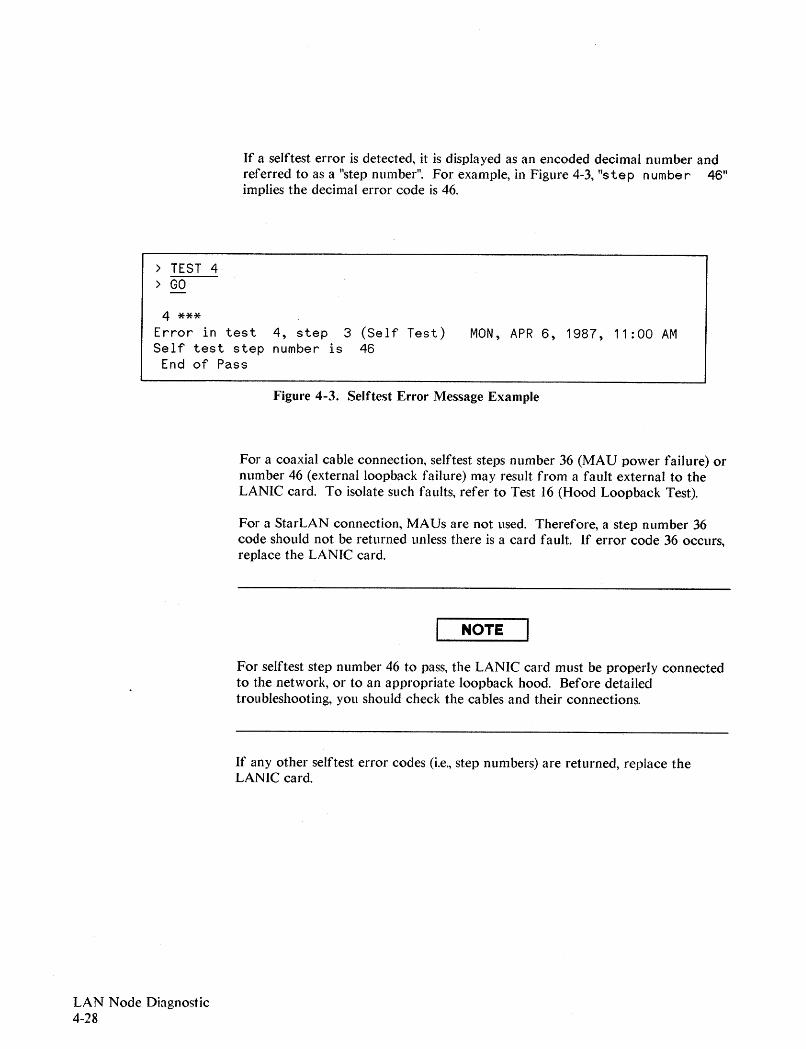
If a selftest error is detected, it is displayed as an encoded decimal number andreferred to as a "step number". For example, in Figure 4-3, "step number 46"implies the decimal error code is 46.
> TEST 4> GO
4 ***Error in test 4, step 3 (Self Test)Self test step number is 46
End of Pass
MaN, APR 6, 1987, 11:00 AM
Figure 4-3. Selftest Error Message Example
For a coaxial cable connection, selftest steps number 36 (MAU power failure) ornumber 46 (externalloopback failure) may result from a fault external to theLANIC card. To isolate such faults, refer to Test 16 (Hood Loopback Test).
For a StarLAN connection, MAUs are not used. Therefore, a step number 36code should not be returned unless there is a card fault. If error code 36 occurs,replace the LANIC card.
NOTE
For selftest step number 46 to pass, the LANIC card must be properly connectedto the network, or to an appropriate loopback hood. Before detailedtroubleshooting, you should check the cables and their connections.
If any other selftest error codes (i.e., step numbers) are returned, replace theLANIC card.
LAN Node Diagnostic4-28

Test #5. Interrupt Test
Test #5 verifies that the LANIC system interrupt mask is functioning properlyand that the LANIC can issue a system interrupt 1. Note that system interrupt 0was checked in test 4. These are the only two system interrupts that the LANICca rd can issue.
This test is comprised of 4 steps:
Step 1: The diagnostic issues an IMB/SIMB INIT instruction to place theLANIC card into a known state. It then writes the skip selftest code tothe control register and starts the Z80 by writing to the selftest controlregister. This should put the LANIC in the kernel state. Finally, thediagnostic reads the osn register. If the device number field of theOBn register is not equal to 1 then Step 1 fails.
A Step 1 failure most likely indicates a LANIC card fault. Replace theLANIC card.
Step 2: The diagnostic then checks the IRQ bit of the OBn register. Since theLANIC interrupt mask is cleared, the IRQ bit should be unasserted. Ifthe IRQ bit is asserted then Step 2 fails, otherwise it passes.
A Step 2 failure most likely indicates a LANIC card fault. Replace theLANIC card.
Step 3: The diagnostic issues a NOP kernel command to the LANIC cardwhich should cause it to respond with a system interrupt 1. However,since the LANIC interrupt mask is still not set, the interrupt should beinternally pending. The diagnostic reads the OBn register and verifiesthat the IRQ bit is still unasserted. If the IRQ bit is asserted, Step 3fails.
A Step 3 failure most likely indicates a LANIC card fault. Replace theLANIC card.
Step 4: The diagnostic does the following:
a. Checks whether any interrupts have been detected since the testbegan,
b. sets the LANIC interrupt mask, and then
c. checks to see if the pending interrupt from step 3 is detected.
If either an interrupt was detected before the mask was set, or nointerrupt is detected after the mask is set, Step 4 fails.
A Step 4 failure most likely indicates a LANIC card fault. Replace theLANIC card.
LAN Node Diagnostic4-29
Test #6. Soft Reset Test
Test #6 verifies that a host write to the soft reset register does indeed cause asoft re;et in the LANIC. card. There are 3 steps to this test:
Step I: The diagnostic performs the following:
a. Issues an INIT to the LANIC card,
b. Writes to the control register the code indicating that a full selftest is to be run,
c. Checks the status of the CRFULL bit, which should be set,acknowledging the control register write.
If the CRFULL bit is not set, Step I fails.
A Step I failure most likely indicates a LANIC card fault. Replace theLANIC card.
Step 2: The diagnostic performs the following:
a. Writes to the selftest control register. This causes a hard resetwhich starts the Z80.
b. Sets the interrupt mask which was cleared by the hard reset.
c. Reads the selftest register and verifies that bit 0 is set, indicatingthe self test is running.
If bit 0 of the selftest register is not set, Step 2 fails.
A Step 2 failure most likely indicates a LANIC card fault. Replace theLANIC card.
Step 3: The diagnostic performs the following:
a. Writes OIH to the soft reset register. This should cause a soft reset,which aborts the self test and starts the KERNEL firmware.
b. Writes a NOP to the control register, which causes the KERNEL torespond with a system interrupt 1.
If a system interrupt I is not detected, Step 3 fails.
A Step 3 failure most likely indicates a LANIC card fault. Replace theLANIC card.
LAN Node Diagnostic4-30

Test #7. CR-SR Loop Test
This test verifies that writes to the LANIC card control register (CR), and readsfrom the status register (SR), are processed correctly by the LANIC card.
The LANIC CR-SR kernel command is used for this test. This command causesthe last word read from the control register to be written back out to the statusregister.
There are 6 steps to this test:
Step 1: Reset the LANIC card and issue the CR-SR loop kernel command withthe test pattern == AAAAH. If an error is detected while issuing thekernel command, Step 1 fails.
A Step 1 failure most likely indicates a LANIC card fault. Replace theLANIC card.
Step 2: After the kernel command completes, a system interrupt 1 should beissued indicating to the host that the command has completed. If asystem interrupt 1 is not detected then Step 2 fails.
A Step 2 failure most likely indicates a LANIC card fault. Replace theLANIC card.
Step 3: The diagnostic then reads the status register. This register shouldcontain the alternating 1's and O's test pattern (AAAAH) written to thecontrol register in Step 1. If the statns register does not containAAAAH step 3 fails.
A Step 3 failure most likely indicates a LANIC card fault. Replace theLANIC card.
Step 4: The diagnostic again issues the CR-SR loopback kernel command, thistime with 5555H as the test pattern. If an error is detected whileissuing the command, Step 4 fails.
A Step 4 failure most likely indicates a LANIC card fault. Replace theLANIC card.
LAN Node Diagnostic4-31
LAN Node Diagnostic4-32
Step 5: After the kernel command completes, a system interrupt I should beissued indicating to the host that the command has completed. If asystem interrupt I is not detected, Step 5 fails.
A Step 5 failure most likely indicates a LANIC card fault. Replace theLANIC card.
Step 6: The diagnostic reads the status register. It should contain the testpattern 5555H, the last word written to the control register in theCR-SR kernel command. If the status register does not contain 5555H,Step 6 fails.
A Step 6 failure most likely indicates a LANIC card fault. Replace theLANIC card.
Test #8. Bus Conflict Test
Test #8 verifies that simultaneous requests made on the LANIC card backplaneinterface from both the LANIC card main module and the IMB/SIMB areproperly arbitrated. The interlock kernel command is used to invoke writealternating AAAAH and 5555H test patterns to the status register. Concurrently,the host is reading the status register. If there is an arbitration error, one or morestatus register reads by the host will be other than the test patterns describedabove.
There are 2 steps to this test:
Step 1: The LANIC is first reset, which should place it in the kernel state,ready to accept commands from the host. The interlock command isthen issued and the return code checked. If an error was detectedwhile issuing the kernel command, Step 1 fails.
A Step 1 failure most likely indicates a LANIC card fault. Replace theLANIC card.
Step 2: The diagnostic reads the status register 500 times with interruptsdisabled. The interrupts are disabled to ensure that the 500 statusregister reads take place while the LANIC is executing the interlockkernel command. The diagnostic then verifies that each of the statusregister reads was either AAAAH or 5555H. If an invalid test patternis detected, Step 2 fails.
A Step 2 failure most likely indicates a LANIC card fault. Replace theLANIC card.
LAN Node Diagnostic4-33
Test #9. Address Offset Test
Test #9 verifies the operation of the LANIC card IMB/SIMB address drivers.The download kernel command is an integra) part of the test. It is used todownload a block 'of words from host memory. The success of the transaction ischecked by comparing its computed checksum to that computed by thediagnostic. Note that 'Data Bus' failures can also cause a bad checksum;however, these failures should be exposed by Test #4 (Self Test) or Test #7(CR-SR Loopback), depending on the location of the fault.
There are 5 steps to this test:
Step 1: The diagnostic first places the LANIC in the kernel state, ready toaccept interactive commands from the host. It then enables theLANIC master handshake circuitry, thus allowing the LANIC to readform host memory. This step fails if either the LANIC card was notsuccessfully placed in the kernel state, or the master handshake couldnot be enabled.
A Step 1 failure most likely indicates a LANIC card fault. Replace theLANIC card.
Step 2: A block of words from bank 1 in host memory is read aQd a checksumcomputed by the diagnostic. The LANIC card is then instructed toread the same block of words via the download kernel command.Finally, the diagnostic once again reads the same block of words fromhost memory. If the first and second read by the diagnostic are not thesame, the sequence of three host memory reads -- by the diagnostic andLANIC card -- is repeated. This is done up to 3 additional times, afterwhich the diagnostic aborts Step 2 and reports a failure.
A failure of Step 2 does NOT indicate a LANIC card fault. Itindicates that the diagnostic was unable to use the predefined testblock for this test -- either it changed too often or a memory failureexists. Try to rerun this test when the system is under less load.
Step 3: After it issued the download kernel command in Step 2, the diagnostic:
- waited for a system interrupt I from the LANIC card indicatingthat the download had completed, and
- read the status register which contained the completion code fromthe kernel indicating whether the checksums matched.
If either a system interrupt I was not detected, or the completion codedid not indicate a successful download, Step 3 fails.
The successful completion of Step 2 and a failure in Step 3 most likelyindicates a LANIC card fault. Replace the LANIC card.
LAN Node Diagnostic4-34

Step 4: The diagnostic reads a block of words in bank 1 of memory, however,the bank offset is chosen so that the address lines are the complementof those used in Step 2. The diagnostic then instructs the LANIC cardto read the same block of words and compare the the checksum tothat computed by the diagnostic. The diagnostic reads the test blockagain and compares it to the first read. If the first and second read donot match, the sequence of three host memory reads between thediagnostic and LANIC is repeated. This is done up to 3 additionaltimes, after which the diagnostic aborts Step 4 and reports a failure.
A failure in Step 4 does NOT indicate a failure of the LANIC. Itindicates that the diagnostic was unable to use the predefined testblock for this test because either it changed too often, or a memoryfailure exists. Try to rerun this test when the system is under less load.
Step 5: After it issued the download kernel command in Step 4, the diagnostic:
- waited for a system interrupt 1 from the LANIC card indicatingthat it had completed the download, and
- read the status register which contained the completion code fromthe kernel indicating whether the checksums matched.
If either a system interrupt I was not detected, or the completion codedid not indicate a successful download, Step 5 fails.
If Step 4 completes successfully while Step 5 fails, a LANIC card faultis likely. Replace the LANIC card.
LAN Node Diagnostic4-35
Test #10. Extended Address Test
Test #10 verifies the operation of the LANIC card extended address bus drivers.Like the Address Offset test (Test #9), the diagnostic uses the download kernelcommand to download a block of words from host memory, and checks thesuccess of the transaction. The diagnostic starts with bank 1 and proceeds bankby bank until the next bank to be tested exceeds the maximum bank ofconfigured memory.
Note that this test depends on the amount of memory configured in the host.Only those extended address bits required to access this memory are tested.
Also, note that failures of the 'Data Bus' or 'Lower (Offset) Address Bus' on theLANIC card could cause this test to fail. However, such failures should beexposed in previous tests (e.g., Self Test, CR-SR Loopback and/or Address Offsettests).
Step I: The diagnostic performs the following:
- prepares the LANIC card for this test by placing it in the kernelstate, and
- enables its master handshake.
If the diagnostic detects an error either while placing the LANIC cardin the kernel state, or attempting to enable master handshake, Step 1fails.
A Step 1 failure most likely indicates a LANIC card fault. Replace theLANIC card.
The following steps are systematically repeated (i.e., first Step X, then Step Y) foreach memory bank tested:
Step X: The diagnostic reads a block of words from bank N (where N = 1,2,4,8, ..., until the next bank to be tested exceeds the maximum bank ofconfigured memory) in host memory and computes the checksum. TheLANIC card is then instructed to read the same block of words via thedownload kernel command. Finally, the diagnostic again reads thesame block of words. If the first and second reads by the diagnosticare not the same, the entire sequence is repeated. This is done up to 3additional times, after which the diagnostic aborts the test on this bankand reports a failure in this step.
A failure in Step "X" does NOT indicate a failure of the LANIC. Itindicates that the diagnostic was unable to use a specific bank of hostmemory for this test because either it changed too often, or a memoryfailure exists. Try to rerun this test when the system is under less load.
LAN Node Diagnostic4-36
Step Y: After it issued the download kernel command in the previous step(Step X), the diagnostic:
- waited for a system interrupt I from the LANIC card indicatingthat the transaction completed, and
- read the status register that contained the completion code fromthe kernel indicating whether the checksums matched.
If either a system interrupt 1 was not detected, or the completion codedid not indicate a successful download, this step fails.
A failure in Step Y (presuming Step X passed) most likely indicates aLANIC card fault. Replace the LANIC card.
LAN Node Diagnostic4-37
Test #11. FIFO Write Test
Test #11 exercises the LANIC card master handshake logic not tested by. theAddress Offset test (Test #9). Firmware is downloaded to the LANIC card thatwill write a predefined test frame into the extra data segment allocated to thediagnostic. The diagnostic then compares its copy of the test frame to thatwritten by the LANICcard. An error is reported if the frames are not the same.
The test includes 5 steps:
Step 1: The LANIC card is reset and the master handshake is enabled, therebypreparing it for the download process. If either the reset or handshakeenable were not successful then Step 1 fails.
A Step I failure most likely indicates a LANIC card fault. Replace theLANIC card.
Step 2: The diagnostic moves the firmware to the LANIC card via thedownload kernel command. Then, it waits for a system interrupt 1that indicates the download has completed.
After the interrupt is detected, or a time out occurs, the diagnosticreads the download completion code from the status register. If eitherthe interrupt is not detected, or an unsuccessful completion code isencountered, Step 2 fails.
A failure of Step 2 most likely indicates a LANIC card fault. Replacethe LANIC card.
If a failure was detected while attempting to download the firmware,the diagnostic will not continue the test, that is, Steps 3 thru 5 are notperformed.
Step 3: If the download was successful, the LANIC is instructed to startexecution of the code. The diagnostic then waits for a systeminterrupt 1 that indicates firmware code completion. If the interrupt isnot detected within the time allotted, Step 3 fails.
A failure of Step 3 most likely indicates a LANIC card fault. Replacethe LANIC card.
LAN Node Diagnostic4-38
Step 4: Before issuing the system interrupt 1, the firmware writes a completioncode into the status register. The diagnostic then reads the completioncode from the status register.
If the completion code does not indicate the test completed withouterror, Step 4 fails.
A failure of Step 4 most likely indicates a LANIC card fault. Replacethe LANIC card.
Step 5: In this step, the diagnostic compares its copy of the downloaded testframe with that returned by the LANIC card. If the frames do notmatch, Step 5 fails.
A failure of Step 5 most likely indicates a LANIC card fault. Replacethe LANIC card.
LAN Node Diagnostic4-39
Test #12. F/P Conflict Test
Test #12 verifies that the LANIC card is able to properly arbitrate masterhandshake requests between its "first-in-first-out" (FIFO) buffers and processor.
The following sequence is performed:
- The FIFOs are loaded with 16 words of a test frame and are held off fromwriting to system memory until instructed by the host.
- After the FIFOs are full, the Z80 processor notifies the host that theLANIC is ready to start the test.
- Upon receiving the acknowledgment, the Z80 will simultaneously enablethe FIFO writes to system memory and write its own test frames toanother section of system memory.
- The diagnostic will pause to allow the processor and FIFOs time tocomplete their writes to host memory.
- The Z80 processor checks the FIFO out/in status before its first and secondwrite to host memory and after its last write.
- The Z80 processor then reports the results in the status register.
There are 5 steps to this test:
Step 1: The LANIC card is reset and its master handshakes enabled inpreparation for the download process. If an error was detected duringthis initialization Step 1 fails.
A Step 1 failure most likely indicates a LANIC card fault. Replace theLANIC card.
Step 2: In this step, the following occurs:
- The diagnostic erases any previous data from the extra datasegment to prevent interpretation of erroneous data.
- The diagnostic dow.nloads firmware to the LANIC card, then waitsfor a system interrupt 1 (download completion) or a time out.
- After the interrupt or time out, the diagnostic reads the statusregister. The register should contain the completion code of thedownload process.
LAN Node Diagnostic4-40
If either the interrupt was not detected, or the completion codeindicates an unsuccessful transaction, Step 2 fails.
A failure in Step 2 most likely indicates a LANIC card fault. Replacethe LANIC card.
The following steps are executed only if Step 2 passes:
Step 3: In this step, the following occurs:
- The diagnostic issues the start code kernel command to startexecution of the downloaded firmware.
- The diagnostic waits for a system interrupt 1, indicating thefirmware has finished setting up the test.
- The status register is read for the appropriate initializationcompletion code provided by the firmware.
If the interrupt is not detected after a predefined interval, or thecompletion code indicates the LANIC did not set up correctly, Step 3fails.
A failure of Step 3 most likely indicates a LANIC card fault.
Replace the LANIC card.
Step 4: If a system interrupt 1 is correctly received in Step 3, the diagnosticwrites the GO command to the control register. This causes the FIFOand Z80 processor to write to host memory in a round robin fashion.Subsequently, the diagnostic waits for a system interrupt 1, indicatingthe LANIC card has completed the test.
After an interrupt or time out, the diagnostic reads the completioncode in the status register. If either the interrupt was not detected, orthe completion code does not indicate successful completion of thefirmware, Step 4 fails.
A Step 4 failure most likely indicates a LANIC card fault. Replace theLANIC card.
Step 5: Finally, the diagnostic moves the test frames (written by the FIFOs andZ80 processor) from the extra data segment to the stack, and checkstheir contents. If they contain errors, Step 5 fails.
~
A Step 5 failure most likely indicates a LANIC card fault. Replace theLANIC card.
LAN Node Diagnostic4-41
Test #13. Coprocessor Test
Test #13 verifies that the LAN coprocessor (INTEL 82586) can detect/report aCRC error and correctly process multicast frames received by it.
There are 5 steps to this test:
Step 1: In this step, the following occurs:
- The diagnostic resets the LANIC card and downloads firmware.
- The diagnostic waits for a system interrupt 1, indicating thedownload has completed, or a time out.
- After the interrupt or timing out, the diagnostic reads the statusregister for the proper completion code of the download process.
If the interrupt was not detected, or the completion code indicates anunsuccessful transaction, Step 1 fails.
A Step 1 failure most likely indicates a LANIC card fault. Replace theLANIC card.
Step 2: If the download was successful,
- the diagnostic initiates the downloaded code and waits for a systeminterrupt 1 from the LANIC card.
- It reads the status register and checks for the proper status codethat indicates the firmware is ready to continue testing.
If a system interrupt I is not detected, or the code in the status registerindicates an error, Step 2 fails.
A failure in Step 2 most likely indicates a LANIC card fault. Replacethe LANIC card.
LAN Node Diagnostic4-42

The following steps are executed only if Steps I and 2 pass.
Step 3: Coprocessor Initialization. In this step, the following occurs:
- The diagnostic instructs the firmware to continue the test.
- The diagnostic waits for another system interrupt 1, whichindicates that the firmware has completed the test and has placedthe first result in the status register.
- On detecting the interrupt, or if a time out occurs, the diagnosticreads the first test result from the status register.
If the interrupt is not detected, or the first result reported (Coprocessorinitialization step) has failed, Step 3 fails.
A failure in Step 3 most likely indicates a LANIC card fault. Replacethe LANIC card.
Step 4: Multicast Test. As the firmware test code continues, the diagnosticreads the status register again, which should now contain the results ofthe multicast test. If test results indicate a failure, then Step 4 fails.
A failure in Step 4 most likely indicates a LANIC card fault. Replacethe LANIC card.
Step 5: CRC Test. As the firmware test code continues, the diagnostic readsthe status register again, which should now contain the result of theCRe test. If test results indicate a failure, Step 5 fails.
A failure in Step 5 most likely indicates a LANIC card fault. Replacethe LANIC card.
LAN Node Diagnostic4-43
Test #14. MAU Loopback Test
Test #14 verifies operation of the connection to the LAN. For coaxial cableconnections, this includes the LANIC card, AUI cabling, and MAU/Tap orThinMAU/BNC-Tee, as appropriate. For HP StarLAN connections, this includesthe LANIC card and twisted-pair cable.
NOTE
Despite its name, Test #14 is used for testing connections to an HP StarLAN aswell as a coaxial cable LAN.
For Test #14 to pass, the LANIC cards must be properly connected to afunctional coaxial cable or StarLAN Hub, or to appropriate loopback hoods.
Externalloopback test firmware is downloaded to the LANIC card. This codewill sequentially transmit and receive (i.e., loopback) 8 test frames to and fromthe LAN medium. Results are reported to the diagnostic in the status register.This includes:
1. Whether MAU/ThinMAU power could be turned on (for the StarLANcard, the power line is tested even though there is no MAU/ThinMAUattached).
2. The number of attempts required to turn the MAU/ThinMAU power on(tested for StarLAN cards even though there is no MAU/ThinMAUattached).
3. The number of frames successfully looped back.
4. The number of heartbeats detected from the MAU/ThinMAU (not testedon StarLAN cards).
5. The number of collisions detected.
6. The number of times a transmit was aborted due to excessive collisions.
7. Whether the MAU/ThinMAU jabbed too soon (not tested for StarLANcards).
8. Whether the MAU did not jab at all (not tested for StarLAN cards).
LAN Node Diagnostic4-44
9. Whether the LANIC could reset the MAU from a jabber condition (nottested for StarLAN cards).
10. Whether the SQE disable function on the LANIC is operational (not testedfor StarLAN cards).
There are 9 steps to this test:
Step 1: The diagnostic resets the LANIC card and downloads the externalloopback test firmware. Subsequently, the diagnostic waits for asystem interrupt I indicating the download has completed. A read ofthe status register is made -- it should contain the download completioncode.
If the interrupt is not detected within a predefined time interval, or thecompletion code indicates an unsuccessful transaction, Step I fails.
A Step 1 failure most likely indicates a LANIC card fault. Replace theLANIC card.
Step 2: If the download completed successfully, the diagnostic initiatesexecution of the downloaded firmware. The diagnostic waits for asystem interrupt I, indicating the LANIC card has completedinitialization and is ready to execute the tests. After receiving theinterrupt, or if a time out occurs, the diagnostic reads the status registerfor a ready code returned by the firmware.
If the system interrupt 1 was not detected, or the status register doesnot contain the appropriate ready code, Step 2 fails.
A Step 2 failure most likely indicates a LANIC card fault. Replace theLANIC card.
LAN Node Diagnostic4-45

LAN Node Diagnostic4-46
The following steps are executed only if Steps 1 and 2 passed.
Step 3: MAU/ThinMAU power line tests. If the download and start code(Steps 1 and 2) were correctly returned, the LANIC card is instructedto turn the MAU power supply line on. The diagnostic then waits fora system interrupt 1, indicating completion of this task. Subsequently,the diagnostic reads the status register for results returned by thefirmware.
The results indicate the status of two internal signals, MAUPWR andVI2SENSE, specifically, whether or not MAU/ThinMAU power is onand how many attempts were required to turn the power on.
If the task completion interrupt was not detected, or either of theinternal signals indicate lack of MA U/ThinMAU power, Step 3 fails.
For coaxial cable LAN connections, a Step 3 failure can result from aLANIC card, AUI cable, or MAU/ThinMAU fault. Refer to Test #16(Hood Loopback Test) to find the faulty unit(s).
For StarLAN connections, the LANIC card most likely contains a faultand should be replaced. Test #16 does not operate for StarLANconnections.
Step 4: External loopback tests. The diagnostic instructs the LANIC card toloop 8 test frames to the LAN and back. The firmware transmits andreceives the test frames.
During these loopback tests, the firmware monitors the number ofcollisions, aborts due excessive collisions, heartbeats received from theMAU/ThinMAU (if applicable), and frames received without error.
The diagnostic waits for the LANIC card to issue a system interrupt 1indicating that it has completed the external loopback tests.Subsequently, the status register is read for results returned by thefirmware. If the interrupt is not received, or the number of framesreceived without error is less than four, Step 4 fails.
For a coaxial cable LAN, a Step 4 failure may indicate a faulty LANICcard, AUI cable, MAU/Tap or ThinMAU/BNC-tee (as appropriate), orthe coax cable. Using a loopback hood and this test, or Test #16, thefault may be isolated.
For StarLAN, a Step 4 failure may indicate a faulty card, StarLANcable, or StarLAN Hub. Using a StarLAN loopback connector and thistest, the fault can be isolated. See Figure 4-4.
For either type of LAN, a Step 4 failure may indicate excessive trafficon the LAN.
NOTE
For HP StarLAN connections, the following steps in Test #14 are not performed.
Step 5: For coaxial cable LANs, the diagnostic checks the number of times aheartbeat was detected in Step 4. A heartbeat should be detected aftereach successful transmission. If a predefined number of heartbeaterrors occur, Step 5 fails.
A Step 5 failure most likely indicates a MAU/ThinMAU fault.However, it can also occur for AUI cable or LANIC card faults. Use aloopback hood with this test, or Test #16 (Hood Loopback Test), tohelp identify the failure.
Step 6: For coaxial cable LAN connections, the diagnostic instructs the LANICto run the jabber test. The jabber test involves transmitting frames thatexceed allowable frame lengths, and monitoring the Control In (CI)signal pair for MAU/ThinMAU jabber operation.
The SQE disable function of the LANIC card is also tested at this time.
Finally, the firmware resets the MAU/ThinMAU by cycling the power.The CI signal pair is checked to verify that jabber operation in theMAU/ThinMAU has been reset.
While the firmware executes this test, the diagnostic is waiting for asystem interrupt 1, indicating that the test has completed. After itdetects the interrupt, or a time out occurs, the status register is read fortest results returned by the firmware.
If the interrupt was not detected within a predefined time interval, ora jabber condition was detected too early in the test process, Step 6fails.
A Step 6 failure suggests a LANIC card or MAU/ThinMAU fault. Aloopback hood with this test, or Test #16 (Hood Loopback Test) shouldbe used to isolate the faulty unit.
LAN Node Diagnostic4-47
LAN Node Diagnostic4-48
Step 7: From Step 6, the diagnostic checks whether the jabber condition wasdetected in the jabber test. If the test completion system interrupt wasnot detected, or the jabber condition did not occur, Step 7 fails.
A Step 7 failure most likely indicates a MAU/ThinMAU fault.However, LANIC card or AUI cable faults are possible. Use aloopback hood with this test, or Test #16 (Hood Loopback Test), toisolate the faulty unit.
Step 8: The diagnostic checks whether the jabber condition could be reset bycycling the power to the MAU/ThinMAU. If the jabber condition wasnever detected then the results from this test are invalid.
If the test completion system interrupt I was not detected, or thejabber condition appears to be active after MAU/ThinMAU powercycling, Step 8 fails.
A Step 8 failure suggests that LANIC card or MAU/ThinMAU arefaulty. Use a loopback hood with this test, or Test #16 (HoodLoopback Test) to help isolate the fault.
Step 9: The diagnostic checks whether the SQE disable function is operatingproperly. If either the system interrupt I was not detected in Step 6, orthe firmware reports a failure in the SQE disable test, Step 9 fails.
A Step 9 failure most likely indicates a LANIC card fault. Replace theLANIC card.
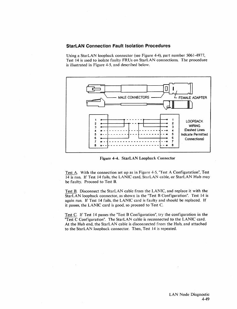
StarLAN Connection Fault Isolation Procedures
Using a StarLAN loopback connector (see Figure 4-4), part number 5061-4977,Test 14 is used to isolate faulty FRUs on StarLAN connections. The procedureis illustrated in Figure 4-5, and described below.
t€J=1 l~],,::::==::::1'>-- MALE CONNECTORS~ FEMALE ADAPTER
I-....-JF===e::::::=:::::=:::J==g] [J
1 I ------1 I2 ...--+----+-1... - - "--+I---....f-- 23 34 .- ------- ---------- --. 4
5 .------------- -------~-. 56 67 • - - - - - - - - - - - - - - - - - - - • - -. 78 .---------------------~-. 8
Figure 4-4. StarLAN Loopback Connector
LOOPBACKWIRING
(Dashed LinesIndicate Permitted
Connections)
Test A. With the connection set up as in Figure 4-5, "Test A Configuration", Test14 is run. If Test 14 fails, the LANIC card, StarLAN cable, or StarLAN Hub maybe faulty. Proceed to Test B.
Test B. Disconnect the StarLAN cable from the LANIC, and replace it with theStarLAN loopback connector, as shown in the "Test B Configuration". Test 14 isagain run. If Test 14 fails, the LANIC card is faulty and should be replaced. Ifit passes, the LANIC card is good, so proceed to Test C.
Test C. If Test 14 passes the "Test B Configuration", try the configuration in the"Test C Configuration". The StarLAN cable is reconnected to the LANIC card.At the Hub end, the StarLAN cable is disconnected from the Hub, and attachedto the StarLAN loopback connector. Then, Test 14 is repeated.
LAN Node Diagnostic4-49
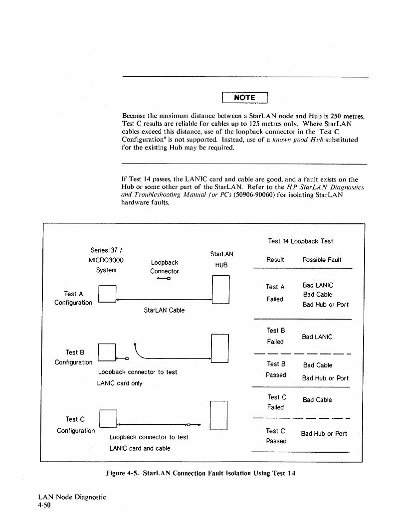
NOTE
Because the maximum distance between a StarLAN node and Hub is 250 metres,Test C results are reliable for cables up to 125 metres only. Where StarLANcables exceed this distance, use of the loopback connector in the "Test CConfiguration" is not supported. Instead, use of a known good Hub substitutedfor the existing Hub may be required.
If Test 14 passes, the LANIC card and cable are good, and a fault exists on theHub or some other part of the StarLAN. Refer to the H P StarLAN Diagnosticsand Troubleshooting Manual lor pes (50906-90060) for isolating StarLANhardware faults.
Test 14 Loopback TestSeries 37 I StarLANMICR03000 Loopback Result Possible Fault
HUBSystem Connector
--e .00Test A Bad LANIC
Test AFailed
Bad CableConfiguration Bad Hub or Port
StarLAN Cable
Test B
.0 FailedBad LANIC
~'"Test B --------
Configuration Test B Bad CableLoopback connector to test Passed Bad Hub or PortLANIC card only
Test C Bad Cable
0 Failed
Test C 0 --------IICI 0-
Configuration Test C Bad Hub or PortLoopback connector to test PassedLANIC card and cable
Figure 4-5. StarLAN Connection Fault Isolation Using Test ] 4
LAN Node Diagnostic4-50
Test #15. Date Code Test
Test #15 verifies that the LANIC card and ROM firmware are current. Becausethis test depends on a properly operating LANIC card, it is performed after Tests1 through 14.
This test uses the dump hardware kernel command to read the ROM and LANICcard date codes. It consists of 3 steps:
Step 1: The diagnostic first resets the LANIC card and enables the LANICcard master handshake. It then issues the dump hardware kernelcommand and waits for a system interrupt 1, which indicates that thedump is complete. The diagnostic finally moves the dump from theextra data segment to the stack.
If any of the following occurs, Step 1 fails:
- the interrupt was not detected.
- the kernel command was not issued successfully, or
- the data move from the data segment to the stack failed.
A Step 1 failure most likely indicates a LANIC card fault. Replace theLANIC card.
Step 2: The diagnostic checks the ROM date code against the expected datecode hardcoded in the diagnostic. If the ROM date code is earlier inthe time then the date code expected, Step 2 fails.
A Step 2 failure indicates that the LANIC is either an outdated card, orthe dump failed. In either case replace the LANIC card.
Step 3: The diagnostic checks the board date code against expected date codehardcoded in the diagnostic. If the board date code is earlier in timethen the expected date code, Step 3 fails.
A Step 3 failure indicates that the LANIC is either an outdated card, orthe dump failed. In either case replace the LANIC card.
LAN Node Diagnostic4-51
Test #16. Hood Loopback Test
NOTE
Test #16 is not executed with HP StarLAN connections. Attempts to do so willresult in the following message:
Test 16 is not valid for HP30265A StarLANIC
Test #16 is used on coaxial cable LAN connections, and helps identify the faultyunits associated with an external loopback (Test #14) failure. This sectioncontains the following information:
• Required Hardware
• Functional Description
• Using Test 16
Required Hardware
For isolating faults with Test 16, the following hardware is required:
LAN Node Diagnostic4-52
PartNumber
30241 A28641 A
92257B92227Q
30241-60009
30241-60002
30241-60003
Description
Known good MAU or ThinMAU, for ThickLAN orThinLAN connections, respectively.
Terminated loopback hoods for ThickLAN or ThinLANconnections, respectively. See Figures 4-6 and 4-7.
Known good AUI cable for connecting theMAU/loopback hood.
For Series 39/40/42/52, known good Internal Cable,LANIC card to Junction panel. (Used to distinguishLANIC card faults from internal cable faults.)
For Series 44/48/58/6X/70, known good Internal Cable,LANIC card to Junction panel. (Used to distinguishLANIC card faults from internal cable faults.)
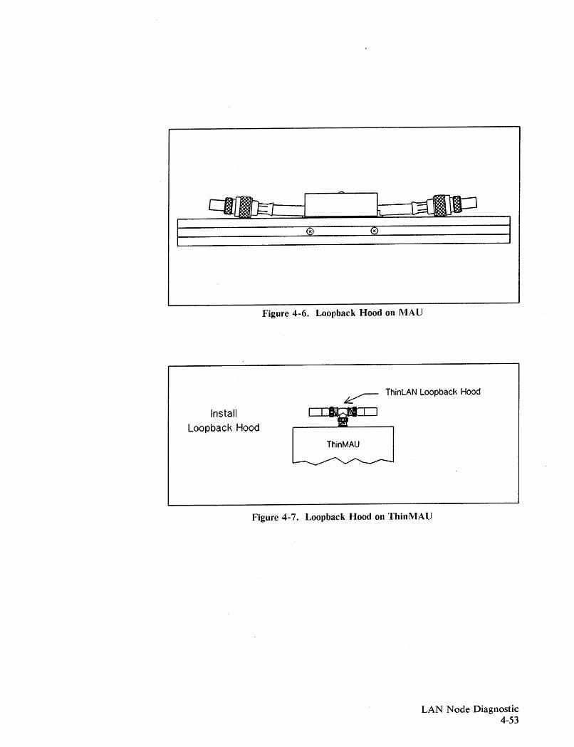
Figure 4-6. Loopback Hood on MAU
~ ThinLAN Loopback Hood
Install
Loopback Hood
ThinMAU
Figure 4-7. Loopback Hood on ThinMAU
LAN Node Diagnostic4-53
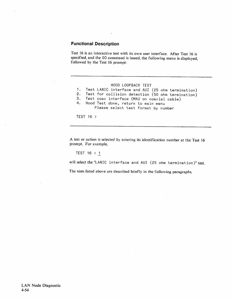
LAN Node Diagnostic4-54
Functional Description
Test 16 is an interactive test with its own user interface. After Test 16 isspecified, and the GO command is issued, the following menu is displayed,followed by the Test 16 prompt:
HOOD lOOPBACK TEST1. Test LANIC interface and AUI (25 ohm termination)2. Test for collision detection (50 ohm termination)3. Test coax interface (MAU on coaxial cable)4. Hood Test done, return to main menu
Please select test format by number
TEST 16 >
A test or action is selected by entering its identification number at the Test 16prompt. For example,
TEST 16 > 1
will select the "LANIC interface and AUI (25 ohm termination)" test.
The tests listed above are described briefly in the following paragraphs.
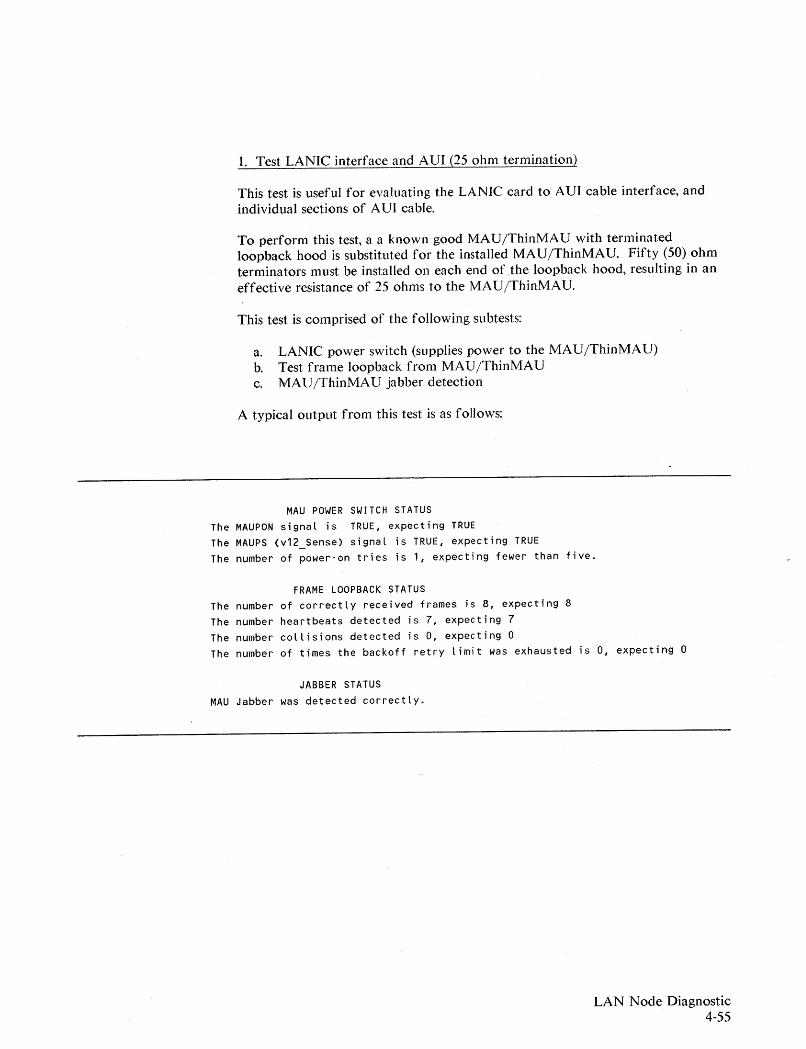
1. Test LANIC interface and AUI (25 ohm termination)
This test is useful for evaluating the LANIC card to AU] cable interface~ andindividual sections of AUI cable.
To perform this test~ a a known good MAU/ThinMAU with terminatedloopback hood is substituted for the installed MAU/ThinMAU. Fifty (50) ohmterminators must be installed on each end of the loopback hood, resulting in aneffective resistance of 25 ohms to the MAU/ThinMAU.
This test is comprised of the following subtests:
a. LANIC power switch (supplies power to the MAU/ThinMAU)b. Test frame loopback from MAU/ThinMAUc. MAU/ThinMAU jabber detection
A typical output from this test is as follows:
MAU POWER SWITCH STATUSThe MAUPON signal is TRUE, expecting TRUEThe MAUPS (v12_Sense) signal is TRUE, expecting TRUEThe number of power-on tries is 1, expecting fewer than five.
FRAME LOOPBACK STATUSThe number of correctly received frames is 8, expecting 8The number heartbeats detected is 7, expecting 7The number collisions detected is 0, expecting °The number of times the backoff retry limit was exhausted is 0, expecting °
JABBER STATUSMAU Jabber was detected correctly.
LAN Node Diagnostic4-55
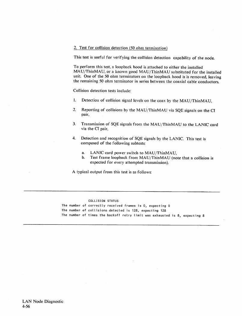
2. Test for collision detection (50 ohm termination)
This test is useful for verifying the collision detection capability of the node.
To perform this test, a loopback hood is attached to either the installedMAU/ThinMAU, or a known good MAU/ThinMAU substituted for the installedunit. One of the 50 ohm terminators on the loopback hood is is removed, leavingthe remaining 50 ohm terminator in series between the coaxial cable conductors.
Collision detection tests include:
1. Detection of collision signal levels on the coax by the MAU/ThinMAU,
2. Reporting of collisions by the MAU/ThinMAU via SQE signals on the CIpair,
3. Transmission of SQE signals from the MAU/ThinMAU to the LANIC cardvia the CI pair,
4. Detection and recognition of SQE signals by the LANIC. This test iscomposed of the following subtests:
a. LANIC card power switch to MAU/ThinMAU,b. Te.st frame loopback from MAU/ThinMAU (note that a collision is
expected for every attempted transmission).
A typical output from this test is as follows:
COLLISION STATUS
The number of correctly received frames is 0, expecting 0The number of collisions detected is 128, expecting 128The number of times the backoff retry limit was exhausted is 8, expecting 8
LAN Node Diagnostic4-56

3. Test coax interface (MAU on coaxial cable)
This test serves as a final evaluation of the node connected to the network coax.Faults associated with a coaxial cable Tap (for ThickLAN connections), or faultsexternal to the node (i.e., network faults), can be detected.
This test is comprised of the foHowing subtests:
a. LANIC power switch (supplies power to the MAU/ThinMAU).b. Test frame loopback from a MAU/ThinMAU connected to the network.
A typical output from this test is as follows:
MAU POWER SWITCH STATUSThe MAUPON signal is TRUE, expecting TRUEThe MAUPS (V12_Sense) signal is TRUE, expecting TRUEThe number of power-on tries is 1, expecting fewer than five.
FRAME LOOPBACK STATUSThe number of correctly received frames is 8, expecting 8The number of heartbeats detected is 7, expecting 7The number of collisions detected is 0
(expected value depends on the amount of network traffic)The number of times the backoff retry limit was exhausted is 0
(expected value depends on the amount of network traffic)
LAN Node Diagnostic4-57
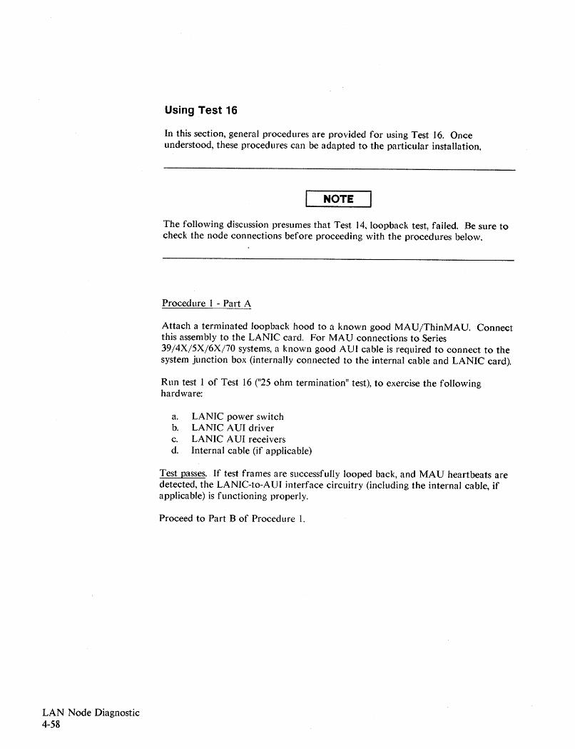
LAN Node· Diagnostic4-58
Using Test 16
In this section, general procedures are provided for using Test 16. Onceunderstood, these procedures can be adapted to the particular installation.
NOTE
The following discussion presumes that Test 14, loopback test, failed. Be sure tocheck the node connections before proceeding with the procedures below.
Procedure 1 - Part A
Attach a terminated Joopback hood to a known goodMAU/ThinMAU. Connectthis assembly to the LANIC card. For MAU connections to Series39/4X/5X/6X/70systems, a known good AUI cable is required to connect to thesystem junction box (internally connected to the internal cable and LANIC card).
Run test 1 of Test 16 ("25 ohm termination" test), to exercise the followinghardware:
a. LANIC power switchb. LANIC AUI driverc. LANIC AUI receiversd. Internal cable (if applicable)
Test passes. If test frames are successfully looped back, and MAU heartbeats aredetected, the LANIC-to-AVI interface circuitry (including the internal cable, ifapplicable) is functioning properly.
Proceed to Part B of Procedure l.
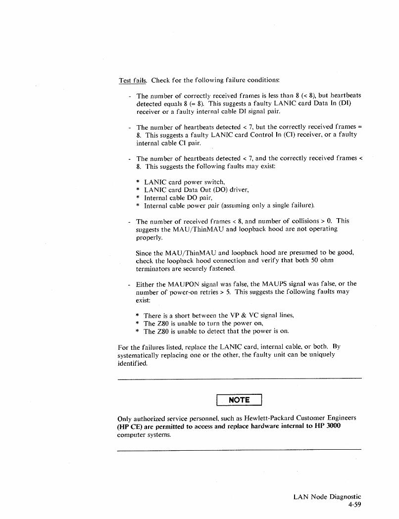
Test fails. Check for the following failure conditions:
- The number of correctly received frames is less than 8 « 8), but heartbeatsdetected equals 8 (= 8). This suggests a faulty LANIC card Data In (DI)receiver or a faulty internal cable DI signal pair.
- The number of heartbeats detected < 7, but the correctly received frames =8. This suggests a faulty LANIC card Control In (CI) receiver, or a faultyinternal cable CI pair.
- The number of heartbeats detected < 7, and the correctly received frames <8. This suggests the following faults may exist:
* LANIC card power switch,* LANIC card Data· Out (DO) driver,* Internal cable DO pair,* Internal cable power pair (assuming only a single failure).
- The number of received frames < 8, and number of collisions> O. Thissuggests the MAU/ThinMAU and loopback hood are not operatingproperly.
Since the MAU/ThinMAU and loopback hood are presumed to be good,check the loopback hood connection and verify that both 50 ohmterminators are securely fastened.
- Either the MAUPON signal was false, the MAUPS signal was false, or thenumber of power-on retries> 5. This suggests the following faults mayexist:
* There is a short between the VP & VC signal lines,* The Z80 is unable to turn the power on,* The Z80 is unable to detect that the power is on.
For the failures listed, replace the LANIC card, internal cable, or both. Bysystematically replacing one or the other, the faulty unit can be uniquelyidentified.
NOTE
Only authorized service personnel, such as Hewlett-Packard Customer Engineers(HP CE) are permitted to access and replace hardware internal to HP 3000computer systems.
LAN Node Diagnostic4-59
LAN Node Diagnostic4-60
Procedure 1 - Part B
Remove one of the terminators, and run test 2 of Test 16 ("50 ohmtermination" test). This is a crude verification of the collision detection andindicator circuitry of the node.
Test passes. If the number of times the back off retry limit is exhausted is 8 thencollision detection circuits are functioning properly. Go on to Procedure 2.
Test fails. If the retry limit is exhausted is not 8, then the collision detectioncircuits are faulty. Since the MAU/ThinMA U and loopback hood are presumedgood, check their connection. Since they must operate properly for remainingtests, replace them if there are doubts. If the test continues to fail, systematicallyreplace the LANIC card (and internal cable, if applicable) until the test passes.
Procedure 2
Procedure 2 primarily addresses ThickLAN connections where multiple AVIcables may be installed.
Attach the known good MAU and loopback hood to t.he end each section ofAUI cable starting wit.h the one connected directly to the host. For each sectionof AUI cable, run test 1 of Test 16 (the "25 ohm terminator" test). Figure 4-8illustrates this process.

r-----..., Internal
Cable
LANIC
HP3000
Known Good MAU
with Terminated
Loopback HoodInstalled
MAU
~LAN Cable
/Testing AUI Cable Sections
,..--__..,& Internal Cable
o ~LANIC
HP3000
DLANIC '--i...-.------..-------+------...
HP3000
Figure 4-8. Testing AUI Cable Sections
Test passes. If the number of correctly received frames = 8, and the number ofheartbeats detected = 7, the test passes. Consequently, the AUI cable under test ispresumed good.
LAN Node Diagnostic4-61
LAN Node Diagnostic4-62
Test Fails. Check for the following failure conditions:
- The number of correctly received frames is less than 8 « 8), and thenumber of heartbeats detected equals 7 (= 7). This suggests a faulty DJsignal pair of the AUf cable.
- The number of correctly received frames = 8, and the number ofheartbeats detected < 7. This suggests a faulty CI signal pair of the AVIcable.
- The number of correctly received frames < 8, and numberof heartbeatsdetected < 7. This suggests a faulty DO signal pair, or faulty power pairthe AUI cable.
- MAUPON or MAUPS indicates "fa 1se", or the number of power-onretries> 5. This suggests a short circuit between the VP & VC lines in theAUI cable under test.
After all AUI cable sections have been tested and presumed good, proceed toProcedure 3.
Procedure 3
Procedure 3 addresses MAU/ThinMAU or coaxial cable faults.
Attach a loopback connector to the original MAU/ThinMAU. Using thisassembly in place of the known good MAU/ThinMAU, repeat Procedure 1, PartsA and B, to verify operation of the MAU/ThinMAU.
Test passes. If errors are not indicated, the MAU/ThinMAU is presumed good,and the fault is presumed to be elsewhere on the LAN cable (e.g., a Tap/BNC tee,cable or remote node fault). You will need to perform other tests. (see "Othertests", below).
Test fails. If errors occur, replace theMAU/ThinMAU, reconnect the node tothe network; and run test 3 of Test 16.
Other tests. To test the original Tap, try moving to some other node location (i.e.,some other Tap) on the same coax, and run test 3 of Test 16. If no errors areindicated, the original Tap is probably faulty. If errors persist, the original Tap isprobably good, and the fault exists elsewhere (coax cable or other node).
To troubleshoot the coax network, refer to the LAN Link HardwareTroubleshooting Manual (5955-7681).
After the network fault is corrected, reconnect the local node and verifyoperation by running test 3 of Test 16.

Test #17. Remote Node Test
Test #17 allows the user to send frames to, and receive frames from, remotenodes on the network. This test assists in diagnosing network faults that lieoutside of the local node hardware. Such faults include:
- topological problems- faulty hardware in the remote nodes- network performance degradation
This section contains the following information:
• Requirements
• Functional Description
• Interpreting Test 17
Requirements
Before running Test 17, there are various requirements that must be met.
Local Node Requirements.
- LDEV number. You must know the LDEV number of your LANIC card.
- "AVAILABLE" state. If your LANIC card is not "AVAILABLE", that is,the line is "DISCONNECTED" or "CLOSED", you must shut down LANactivity on your computer.
- Good node hardware. Using other diagnostic tests, the operation of thelocal node hardware has been verified (i.e., good LANIC card, AUI orStarLAN cables, MAU/ThinMAU as appropriate).
- LANDIAG tests I - 15. In a given LANDIAG session, the default series oftests, Tests 1 through 15, must have been run prior to Test 17.
LAN Node Diagnostic4-63

LAN Node Diagnostic4-64
Remote Node Requirements.
- Station (link-level) address. You must know the 12-digit hexadecimalstation address of the remote LANIC card. The best source for thisinformation is the Network Map.
The station address of the remote node can be determined through the useof software on the remote node. Since you cannot use LANDJAG3000/Vto remotely determine this address, you must be at the remote computer toidentify the station address.
If your remote computer is a Hewlett- Packard personal computer (orequivalent) supported on the network, use the DIAGNET or DIAGLINKutility to find the station address (refer to the H P StarLAN Diagnosticsand Troubleshooting Manual lor PCs, 50906-90060, or the H P ThinLANDiagnostics and Troubleshooting Manual lor PCs, 50909-90060).
If the remote computer is an HP 3000 MPE-V system, use theLANDIAG3000/V "HELP" command.
- If the remote computer is an HP 3000 MPE-V system, its response to theRNT requires its driver be active. The driver is active if
a. a network service must be running (e.g., NS3000/V) and have controlof the LANIC card, or
b. a Test 17 must ha ve been initiated but held in a wait state (waitingfor a carriage return that actually starts the transmit/receive process).
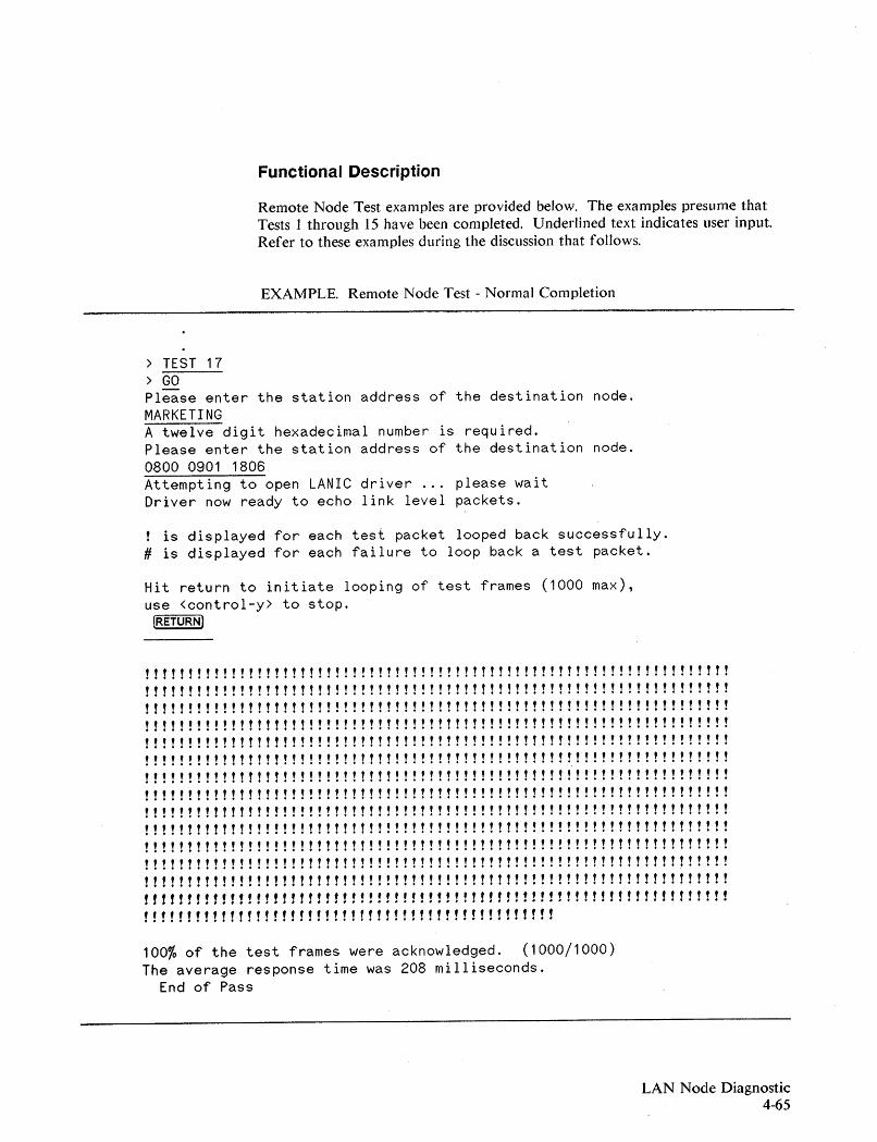
Functional Description
Remote Node Test examples are provided below. The examples presume thatTests 1 through 15 have been completed. Underlined text indicates user input.Refer to these examples during the discussion that follows.
EXAMPLE. Remote Node Test - Normal Completion
> TEST 17> GOPlease enter the station address of the destination node.MARKETINGA twelve digit hexadecimal number is required.Please enter the station address of the destination node.0800 0901 1806Attempting to open LANIC driver ... please waitDriver now ready to echo link level packets.
is displayed for each test packet looped back successfully.# is displayed for each failure to loop back a test packet.
Hit return to initiate looping of test frames (1000 max),use <control-y> to stop.
[RETURNJ
!!!!!!!!!!!!!!!!!!!!!!!!!!!!!!!!!!!!!!!!!!!!!!!!!!!!!!!!!!!!!!!!!!! !tty!!!!!!!!!!!!!!!!!!!!!!!!!!!!!!!!!!!!!!!!!!!!!!!!!!!tty!!!!!!!!!!!tty!!!!!!!!!!!!!!!!!!!!!!!!!!!!!!!!!!!!!!!!!!!!!!!!!!!tty!!!!!!!!!!!tty!!!!!!!!!!!!!!!!!!!!!!!!!!!!!!!!!!!!!!!!!!!!!!!!!!!tty!!!!!!!!!!!tty!!!!!!!!!!!!!!!!!!!!!!!!!!!!!!!!!!!!!!!!!!!!!!!!!!!tty!!!!!!!!!!!!!!!!!!!!!!!!!!!!!!!!!!!!!!!!!!!!!!!!!!!!!!!!!!!!!!!!!!!!!!!!!!!!!! !!! ! ! ! ! ! ! ! ! ! ! ! ! ! ! ! ! ! ! ! ! ! ! ! ! ! ! ! ! ! ! ! ! ! ! ! ! ! ! ! ! ! ! ! ! ! ! ! ! ! ! ! ! ! ! ! ! ! ! ! ! ! ! ! ! ! !tty!!!!!!!!!!!!!!!!!!!!!!!!!!!!!!!!!!!!!!!!!!!!!!!!!!!tty!!!!!!!!!!!tty!!!!!!!!!!!!!!!!!!!!!!!!!!!!!!!!!!!!!!!!!!!!!!!!!!!tty!!!!!!!!!!!tty!!!!!!!!!!!!!!!!!!!!!!!!!!!!!!!!!!!!!!!!!!!!!!!!!!!tty!!!!!!!!!!!! ! ! ! ! ! ! ! ! ! ! ! ! ! ! ! ! ! ! ! ! ! ! ! ! ! ! ! ! ! ! ! ! ! ! ! ! ! ! ! ! ! ! ! ! ! ! ! ! ! ! ! ! ! ! !! ! ! ! ! ! ! ! ! ! ! !tty!!!!!!!!!!!!!!!!!!!!!!!!!!!!!!!!!!!!!!!!!!!!!!!!!!!tty!!!!!!!!!!!tty!!!!!!!!!!!!!!!!!!!!!!!!!!!!!!!!!!!!!!!!!!!!!!!!!!!tty!!!!!!!!!!!"""""""""""""""""",.""""""""""""""".......................... , , .! ! ! ! ! ! ! ! ! ! ! ! ! ! ! ! ! ! ! ! ! ! ! ! ! ! ! ! ! ! ! ! ! ! ! ! ! ! ! ! ! ! !! ! ! ! !
100% of the test frames were acknowledged. (1000/1000)The average response time was 208 milliseconds.
End of Pass
LAN Node Diagnostic4-65
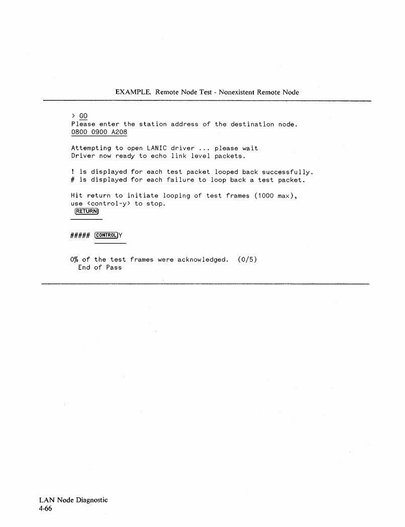
EXAMPLE. Remote Node Test - Nonexistent Remote Node
> GOPlease enter the station address of the destination node.0800 0900 A208
Attempting to open LANIC driver ... please waitDriver now ready to echo link level packets.
is displayed for each test packet looped back successfully.# is displayed for each failure to loop back a test packet.
Hit return to initiate looping of test frames (1000 max),use <control-y> to stop.
[RETURN)
##### ICONTRoLiY
0% of the test frames were acknowledged. (0/5)End of Pass
LAN Node Diagnostic4-66
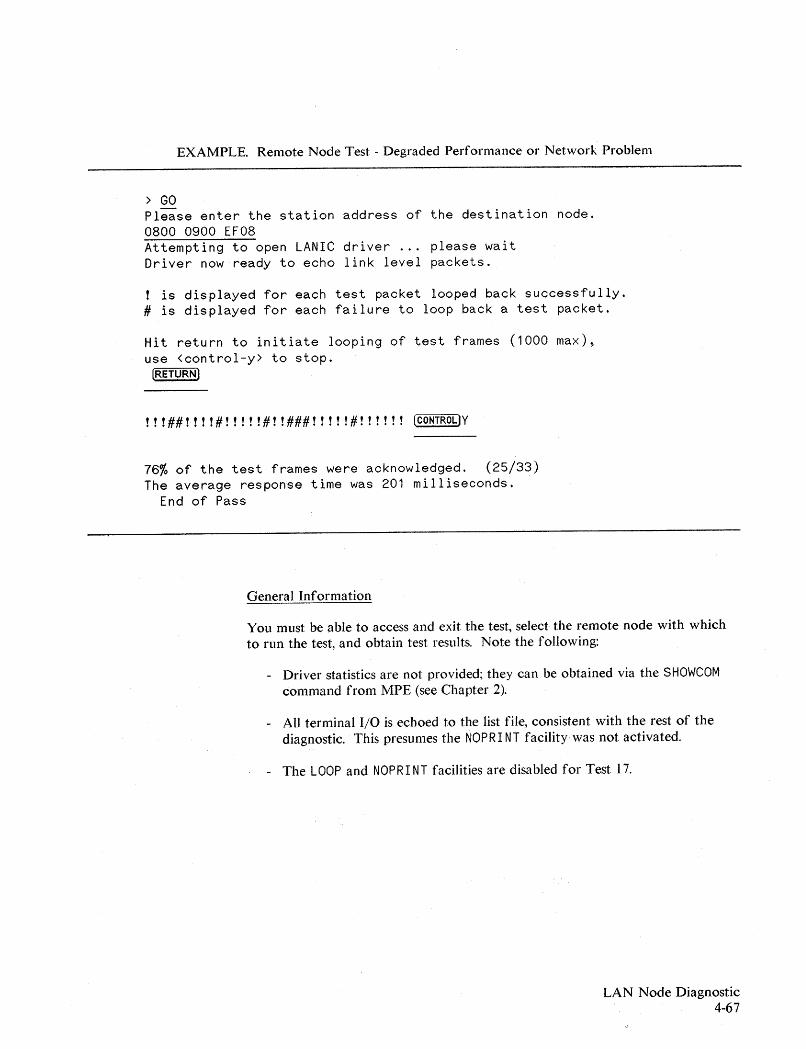
EXAMPLE. Remote Node Test - Degraded Performance or Network Problem
> GOPlease enter the station address of the destination node.0800 0900 EF08Attempting to open LANIC driver ... please waitDriver now ready to echo link level packets.
is displayed for each test packet looped back successfully.# is displayed for each failure to loop back a test packet.
Hit return to initiate looping of test frames (1000 max),use <control-y> to stop.
[RETURN)
!! !##!!! !#!!!! !#! !###!!!! !#!!!!!! [CONTROLlY
76% of the test frames were acknowledged. (25/33)The average response time was 201 milliseconds.
End of Pass
General Information
You must. be able to access and exit the test, select the remote node with whichto run the test, and obtain test results. Note the following:
- Driver statistics are not provided; they can be obtained via the SHOWCOMcommand from MPE (see Chapter 2).
- All terminal I/O is echoed to the list file, consistent with the rest of thediagnostic. This presumes the NOPR I NT facility was not activated.
- The LOOP and NOPR I NT facilities are disabled for Test 17.
LAN Node Diagnostic4-67
LAN Node Diagnostic4-68
Accessing the Remote Node Test
Before accessing the Remote Node Test, ensure all requirements listed in the"Requirements" section have been met.
To run the RNT, specify Test 17 in a TEST command ( > TEST 17), andfollow it with a GO command. Consistent with the diagnostic, subsequent GOcommands will rerun Test 17 if it was the last test specified.
After the GO command is issued, the user is prompted for the station address ofthe remote node. The diagnostic expects a 12-digit hexadecimal number for thestation address (upper or lower case characters are accepted). Leading, trailingand embedded blanks are permitted, as illustrated by the following examples:
hh hh hh hh hh hhhhhh hhhh hhhhhhhhhhhhhhhh
where h is a hexadecimal digit.
If an improper user entry is made, the following message is returned:
A twelve digit hexadecimal number is required.
followed by another prompt for a station address.
If a proper station address is not supplied after four attempts, the diagnosticissues the following message:
Bad input - I assume you want the main menu.
and returns to the LANDIAG command prompt, ">".
Nonexistent Nodes. If a 12 digit hexadecimal number is entered, no further errorchecking is performed. Thus, a proper entry may not be a valid one, that is,there may be no node on the network with the station address specified. Thediagnostic will still try to send test packets to the address entered. Responseframes will not occur, and the "no-reply" timer will expire, resulting in a failure.
NOTE
Test 17 does not distinguish between remote nodes that are broken, too busy torespond, isolated by a network fault, or nonexistent.
Initiating Transmissions. After a proper station address is entered, the LANICcard driver is activated, and the user is directed to "H it retu rn" to start testframe transmission and reception.
NOTE
If [RETURN) is not entered, Test 17 is idle. The ability to have Test 17 idle, that is,to open the driver without actually transmitting test frames, is a necessaryfeature for MPE V systems. This is especially true when the system does nothave network services installed and is the remote node in a Remote Node Test.
On an MPE V system, the LANIC driver must be active with buffers readybefore frames can be received or transmitted. If a remote HP 3000 does nothave network services installed, it can run Test 17 to activate the driver yetremain in an idle state. In this way, it can respond to test frames transmitted bythe local node on which Test 17 is active.
Once [RETURN) is entered, the diagnostic begins sending test frames to the nodespecified and checks for proper response frames.
A test frame transmission and associated response frame reception constitutes asingle test cycle. Each test cycle should be identical to all others. Up to 1000test cycles are attempted unless the diagnostic is interrupted with a [CONTROLjY. Ifa [CONTROLjY is issued during an individual test cycle, the diagnostic will allow thattest cycle to complete before exiting the test.
Activity Indicator
During each test .cycle, either a response frame is received, or a timer within thediagnostic expires. A response frame properly received results in a "! ", while animproper frame or frame not received results in a "#" character.
The return of these characters allows the user to know that the diagnostic isrunning properly.
LAN Node Diagnostic4-69
LAN Node Diagnostic4-70
Test Results
Test 17 Results. When Test 17 completes. either normally or by a "[CONTROLJY",the results of the test are summarized. The following is returned:
- Percent of test frames transmitted that were properly acknowledged. Theactual numbers are also indicated in a ratio format.
- Average response time for response frames acknowledged. This is returnedonly if there were response frames received.
Driver Statistics. The LANIC card driver collects useful statistics about thenode's use of the network. This includes counts of overruns, underruns, CRCerrors, retransmissions required, etc. LANDIAG does not provide this data to theuser; the data is accessed via the SHOWCOM command with the ERROR parameterfrom MPE, as follows:
: SHOWCOM LDE'V; ERROR
Test 17 resets all the statistics. Therefore, for long term intermittent erroranalysis, use SHOWCOM prior to Test 17.
During a network fault isolation process, use SHOWCOM after Test 17. Thestatistics will describe only those network events that have taken place since thelast time the drivel' was opened.
NOTE
For more information on SHOWCOM, see Chapter 2.
Interpreting Test 17
Performance degradation between two nodes can occur from hardware orsoftware faults, extremely busy nodes, or excessive traffic on the network. Test17 can indicate degraded performance if either of the following result:
- Less than 95% of properly transmitted test frames result in properresponses.
- The average response time is more than 550 milliseconds.
On a small network, Test 17 can be run using all remote nodes. On a largenetwork, however, a sampling of nodes might be more appropriate. Whensampling, select nodes that are both near and far, where distance is measured bylengths of network cable a frame must traverse. For problems with a specificnode, run the Remote Node Test with that node.
For network fault isolation, you should refer to the appropriate LANtroubleshooting manual:
- LA N Link Hardware Troubleshooting Manual, 5955-7681, for IEEE 802.3coaxial cable LANs,
- H P StarLA N Diagnostics and Troubleshooting N!anual lor pes,50906-90060, for IEEE 802.3 twisted pair HP StarLAN.
However, the results of Test J7 tests may suggest possible faults that can befurther investigated directly. For example, consider the following:
1. A series of Remote Node Tests indicates that only one remote node isfaulty.
At the faulty node, determine whether NS3000 is up.
Run LANDIAG on that node. Verify that all node FRUs on that system areoperating properly.
If the remote node is connected to a coaxial cable LAN, check for a"marginal" MAUjThinMAU. A node containing a marginalMAUjThinMAU can communicate with nearby nodes, but cannotcommunicate with distant nodes. If LANDIAG Test 16 (MAU loopback)passes while Test 17 (Remote Node) fails for distant nodes only, theMAU jThinMAU should be replaced.
LAN Node Diagnostic4-71
LAN Node Diagnostic4-72
2. Communication is difficult or impossible with every node.
The local node may have a defective FRU. Ensure other tests ofLANDIAG have already been run and passed.
If the local node is connected to a StarLAN, check for a damaged cable orfaulty Hub.
If the local node is connected to a coaxial cable LAN, check for a marginalMAU/ThinMAU (Test 16 passes, Test 17 fails for distant nodes only).Check for loose connectors or terminators. Check the coaxial cable fordamage -- it may be severed, crimped or frayed.
If you have one, a Time Domain Reflectometer (TDR) can be used to testthe coax to locate cable faults. Also, useful information can be gained bymeasuring the resistance across the contacts at the nearest Tap:
a. A resistance of about 25 to 30 ohms between the center conductor andbraided shield is acceptable.
b. A resistance of 50 ohms suggests that one term4nator is absent or thatthere is an open circuit somewhere in the coax.
c. A very large resistance suggests that both terminators are absent.
d. A very small resistance suggests a short between the shield and thecenter conductor.
For resistance faults that are difficult to find, TDR testing is recommended(see the LA N Link Hardware Trollbleshooang M anllal, 5955-7681, for moreinformation).
3. Test 17 results indicate poor response from several adjacent nodes.
For StarLAN connections, the Hub to which the remote nodes areconnected is probably faulty.
For coax connections, the coax may be partially damaged between a nodethat successfully responds and one that does not..
4. For coax connections, Test 17 results indicate performance degrades steadilywith distance from the local node.
The local node probably has a marginal transmitter. Replace theMAUjThinMAU at the local node.
5. All nodes were checked with Test 17, and there was no troublecommunicating with any of them.
If a communication problem exists, it is likely due to a software fault in auser application.
6. Test 17 could not send out any test frames.
a. For some reason, LANDIAG may not have been able to open thedriver. (A CS error code will be returned if this is the case.) Check thefollowing:
- Ensure that NS3000/V is down, and that no other processes are usingthe LANIC card.
- Ensure the LANIC card can pass self test, which is a prerequisite foropening the driver. Selftest failures are commonly due connectionfaults between the LANIC card and the LAN.
b. The diagnostic may have been unable to obtain an extra data segmentto use as a frame buffer. This condition points to a software error.
7. If Test 17 returns a message indicating that Tests 1, 2, 9 and 10 before Test17 can be run, perform these LANDIAG tests.
LAN Node Diagnostic4-73
Error Messages
The following is a list of error messages associated with LANDIAG.
• There is no LANIC present at that location.
The LDEV specified by the user does not respond to a roll call duringinitialization.
• The diagnostic needs driver version 8011000 or newer.
Software compatibility must be maintained between the diagnostic and thedriver. However, it may be possible to continue diagnostic testing in spite of thiswarning.
• The LANIC could not be allocated.
Network Services (NS) is probably running. NS has already allocated the LANICand has not released it.
• An extra data segment could not be created.
This reflects an operating system problem or a system resource shortage.
• That LDEV is not configured as a LANIC.
The LDEV entry in the I/O configuration table is not a LANIC of type 17,subtype 9.
• OP, DI, or 8M capability needed to run diagnostic.
Have the system manager provide you DJ (diagnostician) capability.
• The output file cou ld not be opened.
Logging of diagnostic results to an output file is disabled, but the diagnostic canstill be run.
LAN Node Diagnostic4-74
• Diagnostic not designed for HP3000j30 or 33.
Diagnostic test results on Series 30/33 systems may not be valid; LAN services arenot supported on Series 30s or 33s.
• Bad input - Try again or enter "Help".
Command entry error. The HELP message includes a list of all the commands.
• Test's parameter must be 1 to 17 or "ALL II
•
Parameter error on a TEST command. Note that "ALLII includes Tests 1-15 only.IIALL" is default if no parameter is provided.
• Exit failed to return all resources.
This reflects an operating system problem.
• Bad input - I assume you want the main menu.
Improper parameter entered in Tests 16 or 17 more than three consecutive times.Returns to LANDIAG prompt II> II.
• A small integer input was expected. Please retry.
Test 16 prompt expects input range 1 through 4. Non-numeric character entrywas made.
• Test 1 must run for this test to run.
Test dependency message.
• Test 1 and 2 must pass for this test to run.
Test dependency message.
• Test 1,2,9 and 10 must pass for this test to run.
Test dependency message.
LAN Node Diagnostic4-75
• A twelve digit hexadecimal number is required.
For Test 17 (Remote Node Test), a proper station address must be entered.Leading, trailing and embedded blanks are permitted. Upper and lower casecharacters are accepted.
• MPE commands are not permitted.
Access to MPE, via a colon (:) followed by an MPE command, during aLANDlAG session is not permitted.
• This test can't run while NS/3000 is up.
With NS running and in control of the LANIC card, Tests 3 through 17 cannotbe initiated.
• You must have CS capability to run this test.
For Test 17, capability to use the Communication Subsystem is necessary.
• You must specify an individual address.(The first byte of the address must be even).
For Test 17, a proper station address must be entered. The address cannot be agroup address, that is, its first byte cannot be an odd value.
Test 16 is not valid for the HP30265A StarLANIC.
Test 16 does not apply to systems with HP StarLAN connections. Use Test 14,instead.
LAN Node Diagnostic4-76
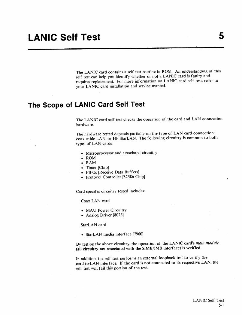
LANIC Self Test 5
The LANIC card contains a self test routine in ROM. An understanding of thisself test can help you identify whether or not a LANIC card is faulty andrequires replacement. For more information on LANIC card self test, refer toyour LANIC card installation and service manual.
The Scope of LANIC Card Self Test
The LANIC card self test checks the operation of the card and LAN connectionhardware.
The hardware tested depends partially on the type of LAN card connection:coax cable LAN, or HP StarLAN. The following circuitry is common to bothtypes of LAN cards:
• Microprocessor and associated circuitry• ROM• RAM• Timer [Chip]• FIFOs [Receive Data Buffers]• Protocol Controller [82586 Chip]
Card specific circuitry tested includes:
Coax LAN card
• MAU Power Circuitry• Analog Driver [8023]
StarLAN card
• StarLAN media interface [7960]
By testing the above circuitry, the operation of the LANIC card's main module(all circuitry not associated with the SIMB/JMB interface) is verified.
In addition, the self test performs an externalloopback test to verify thecard-to-LAN interface. If the card is not connected to its respective LAN, theself test will fail this portion of the test.
LANIC Self Test5-1
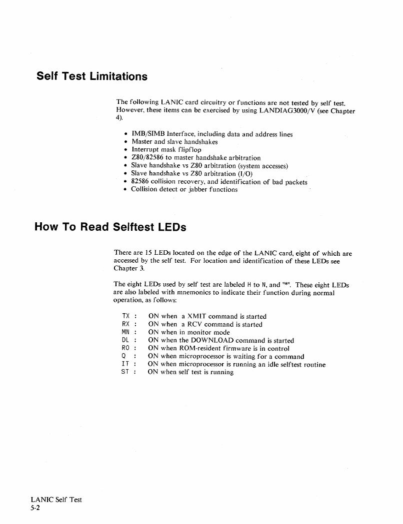
Self Test Limitations
The following LANIC card circuitry or functions are not tested by self test.However, these items can be exercised by using LANDIAG3000/V (see Chapter4).
• 1MB/51MB Interface, including data and address lines• Master and slave handshakes• Interrupt mask flipflop• Z80/82586 to master handshake arbitration• Slave handshake vs Z80 arbitration (system accesses)• Slave handshake vs Z80 arbitration (I/O)• 82586 collision recovery, and identification of bad packets• Collision detect or jabber functions
How To Read Selftest LEOs
There are 15 LEDs located on the edge of the LANIC card, eight of which areaccessed by the self test. For location and identification of these LEDs seeChapter 3.
The eight LEDs used by self test are labeled H to N, and "*". These eight LEDsare also labeled with mnemonics to indicate their function during normaloperation, as follows:
TX ON when a XMIT command is startedRX ON when a RCV command is startedMN ON when in monitor modeDL ON when the DOWNLOAD command is startedRO ON when ROM-resident firmware is in controlQ ON when microprocessor is waiting for a commandI T ON when microprocessor is running an idle selftest routine8T ON when self test is running
LANIC Self Test5-2
Depending on your particular system, the LED labeled "ST" (the rightmost LED)will be in one of three states: off, on, or blinking.
ST is OFF (applies to all MPE-V systems).When the ST is off, self test is not running, and the other seven LEDs performtheir mnemonic functions as noted above.
ST is ON (applies to all MPE-V systems).However, when 8T is on, the self test is in progress. The self test consists ofmany subtests; while the self test is executing, the remaining seven LEDs areused to display a code indicating which subtest is executing. See Table 5-1.
If the self test completes with no errors, the selftest LED will be on and theother seven LEDs will be off (a code of all zeros) for five seconds. After fiveseconds, the self test LED (ST) will go off, and the remaining LEDs performtheir normal LANIC card functions.
ST is Blinking.If self test fails on Series 39j4X/5X/6Xj70 systems, the ST LED will blink slowly,and the code of the subtest that failed will be displayed for about 20 seconds.
The 8T LED does not blink on cards installed on Series 37/MICR03000 systems.If self test fails at power-on, a hexadecimal failure code is returned to the systemconsole under the heading "Local Area Network Interface Controller". Whenself test is initiated from LANDIAG, failures are reported to LANDIAG (seeChapter 4).
LANIC Self Test5-3

How To Use the Self Test
Invoking Self Test
Methods of invoking LANIC card self test depends on the computer type.
LANDIAG. For all MPE-V computer systems, the self test can be invoked byLANDIAG Test #4. Refer to Chapter 4.
Power-On. For all MPE-V computer systems, self test may be manually initiatedby powering on the computer.
For Series 39j4Xj5Xj6Xj70 systems, theself test will first blink the 8 self testLEDs on and off slowly for approximately 13 seconds, after which self test willrun.
For Series 37jMICR03000 systems, self test will simply run at power up.
Reset Switch. For Series 39j4Xj5Xj6Xj70 systems, the LANIC card contains aLANIC Test Reset Switch located on the card edge.
I CAUTION IPressing the reset switch performs a hard reset on the LANIC card before theself test is initiated. Be sure that no network activity is in progress that may bedestroyed by pressing the reset switch.
To use the reset switch to run the self test, perform the following:
1. Ensure the LANIC card is not in use. Do a SHOWCOM and look forLINE UNCONNECTED, or CLOSED.
2. Open the computer card cage to observe the selftest LEDs. Note the presentLED indications. If the ST LED is on, and the remaining seven LEDs aredisplaying a steady pattern, make a written record of which LEDs are lit.(This information may be needed later if the problem persists beyond theinitial steps of troubleshooting.)
3. Press the LANIC TEST RESET switch to initiate the self test. See Chapter 3for location of this switch.
LANIC Self Test5-4
4. Observe the selftest LEDs. Refer to Table 5-1 to interpret the various LEDpatterns displayed.
If the self test completes with no errors, the selftest LED (ST/*) will be onand the LEOs H through N will be off (a code of zeros) for about fiveseconds. Then, the ST/ * LED will go off, and LEOs H through N willperform their normal operating functions.
If the self test fails, the code of the test that failed will be displayed byLEOs H through N and the ST/* LED will blink slowly for at least 20seconds.
Table 5-2 provides codes for unexpected results from the self test. If suchan event occurs, the ST/ * LED will be on (not blinking) and LEOS Hthrough N will display one of the codes described in Table 5-1.
5. If the LANIC fails the self test, the failure is most likely in the LANIC card.However, failures of tests 36 (24 HEX, MAU Power) or 46 (2E HEX,external loopback) may indicate problems with the AUI, MAU, or coax. Ifin doubt, run the self test with a loopback hood, or use LANDlAG
Looping
Looping on the self test is useful for catching intermittent errors.
For all MPE-V systems, selftest looping can be invoked from LANDIAG, usingthe following command sequence:
> LOOP 1000> TEST 4> GO
For Series 39/4X/5X/6X/70 systems, self test may be manually looped bycontinuously depressing the LANIC Test Switch, such as with a clip. The loopingcontinues until a error is detected. Self test will halt with the failed subtestnumber indicated by the selftest LEOs. The ST LED will blink until the switch isreleased.
I CAUTION IIf self test is run during normal LAN activity, the LANIC card and networkoperations will cease. Recovery may be possible in higher software levels;however, avoidance of this situation is recommended. Results of self test may beerroneous.
LANIC Self Test5-5

LANIC Self Test5-6
Observing Self Test
While the self test is cycling through its "subtests", the LEDs will display whichsubtest is running. Refer to the paragraphs under "How to Read Selftest LEDs",presented earlier in this chapter.
Selftest Failure
With two exceptions, replace the LANIC card jf any subtests within the self testfail. The exceptions are:
- Test 36 (24 HEX, MAD Power). Applies to coaxial cable LAN connectionsonly.
- Test 46 (2£ HEX, External loopback). Requires connection to the LAN orapplicable loopback connector to pass.
Failures of these two tests may require additional troubleshooting using aloopback hood and/or LANDIAG.
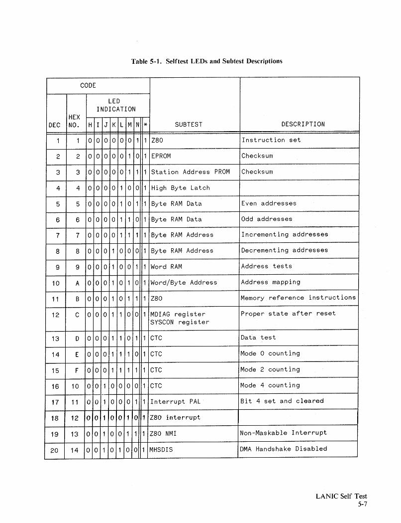
Table 5-1. Selftest LEDs and Subtest Desc.riptions
CODE
LEDINDICATION
HEXDEC NO. H I J K L M N * SUBTEST DESCRIPTION
1 1 0 0 0 o 0 0 1 1 Z80 Instruction set
2 2 0 0 0 0 0 1 0 1 EPROM Checksum
3 3 o 0 o 0 0 1 1 1 Station Address PROM Checksum
4 4 0 0 0 0 1 0 0 1 High Byte Latch
5 5 o 0 o 0 1 0 1 1 Byte RAM Data Even addresses
6 6 o 0 0 0 1 1 0 1 Byte RAM Data Odd addresses
7 7 o 0 0 0 1 1 1 1 Byte RAM Address Incrementing addresses
8 8 o 0 0 1 0 0 0 1 Byte RAM Address Decrementing addresses
9 9 0 0 0 1 o 0 1 1 Word RAM Address tests
10 A 0 0 0 1 0 1 0 1 Word/Byte Address Address mapping
11 B 0 0 0 1 0 1 1 1 Z80 Memory reference instructions
12 C 0 0 0 1 1 0 0 1 MDIAG register Proper state after resetSYSCON register
13 D 0 0 0 1 1 0 1 1 CTC Data test
14 E 0 o 0 1 1 1 0 1 CTC Mode 0 counting
15 F 0 0 0 1 1 1 1 1 CTC Mode 2 counting
16 10 0 0 1 0 0 0 0 1 CTC Mode 4 counting._-
17 11 o 0 1 0 0 0 1 1 Interrupt PAL Bit 4 set and cleared
18 12 o 0 1 o 0 1 0 1 Z80 interrupt
19 13 o 0 1 o 0 1 1 1 Z80 NMI Non-Maskable Interrupt
20 14 o 0 1 0 1 0 0 1 MHSDIS DMA Handshake Disabled
LANIC Self Test5-7
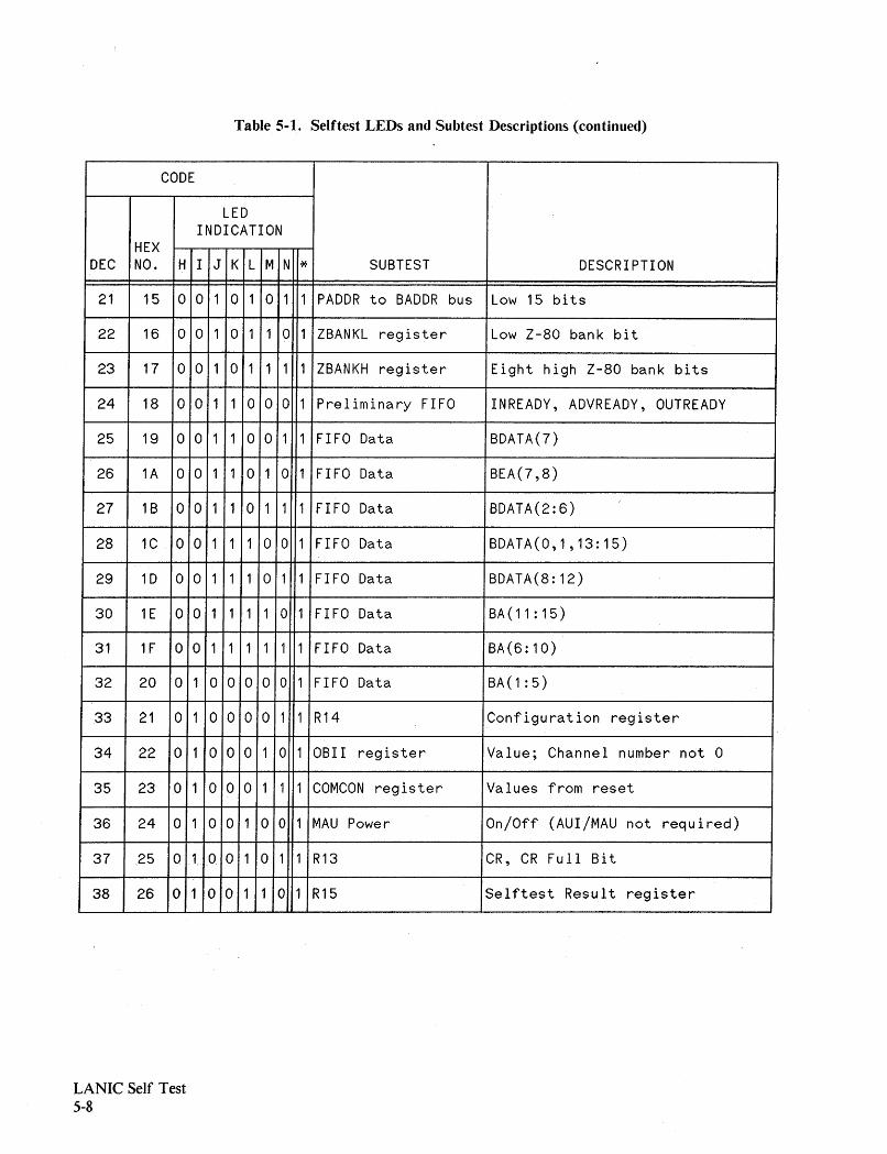
Table 5-1. Selftest LEDs and Subtest Descriptions (continued)
CODE
LEDINDICATION
HEXDEC NO. H I J K L M N * SUBTEST DESCRIPTION
21 15 0 0 1 0 1 0 1 1 PADDR to BADDR bus Low 15 bits
22 16 0 0 1 0 1 1 0 1 ZBANKL register Low Z-80 bank bit
23 17 0 0 1 0 1 1 1 1 ZBANKH register Eight high Z-80 bank bits
24 18 0 0 1 1 0 o 0 1 Prel iminary FIFO INREADY, ADVREADY, OUTREADY
25 19 o 0 1 1 o 0 1 1 FIFO Data BDATA(7)
26 1A 0 0 1 1 0 1 0 1 FIFO Data BEA(7,8)
27 18 0 0 1 1 0 1 1 1 FIFO Data BDATA(2:6)
28 1C 0 0 1 1 1 0 0 1 FIFO Data BDATA(0,1,13:15)
29 1D 0 0 1 1 1 0 1 1 FIFO Data BDATA(8:12)
30 1E 0 0 1 1 1 1 0 1 FIFO Data BA ( 11 : 15)
31 1F 0 0 1 1 1 1 1 1 FIFO Data BA(6:10)
32 20 0 1 0 0 0 0 0 1 FIFO Data BA (1 : 5)
33 21 0 1 0 0 o 0 1 1 R14 Configuration regis"ter
34 22 0 1 0 o 0 1 0 1 OBII register Value; Channel number not 0
35 23 0 1 o 0 0 1 1 1 COMCON register Values from reset
36 24 0 1 0 0 1 0 0 1 MAU Power On/Off (AUI/MAU not required)
37 25 0 1 o 0 1 0 1 1 R13 CR, CR Full Bit
38 26 0 1 o 0 1 1 0 1 R15 Selftest Result register
LANIC Self Test5-8
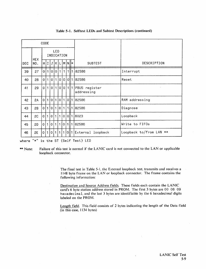
Table 5-1. Selftest LEDs and Subtest Descriptions (continued)
CODE
LEDINDICATION
HEXDEC NO. H I J K L M N * SUBTEST DESCRIPTION
39 27 0 1 0 0 1 1 1 1 82586 Interrupt
40 28 0 1 o 1 0 0 0 1 82586 Reset
41 29 0 1 0 1 0 o 1 1 PBUS registeraddressing
42 2A 0 1 0 1 0 1 0 1 82586 RAM addressing
43 2B 0 1 0 1 0 1 1 1 82586 Diagnose
44 2C 0 1 0 1 1 0 0 1 8023 Loopback
45 2D 0 1 0 1 1 0 1 1 82586 Write to FIFOs
46 2E 0 1 0 1 1 1 0 1 External loopback Loopback to/from LAN **
where "*" is theST (Self Test) LED
** Note: Failure of this test is normal if the LANIC card is not connected to the LAN or applicableloopback connector.
The final test in Table 5-1. the External loopback test, transmits and receives a1148 byte frame on the LAN or loopback connector. The frame contains thefoHowing information:
Destination and Source Address fields. These fields each contain the LANICcard's 6 byte stat.ionaddress st.ored in PROM. The first. 3 byt.es are 00 08 09hexadec ima 1, and the last 3 byt.es are identifiable by the 6 hexadecimal digitslabeled on the PROM.
Length field. This field consists of 2 bytes indicating the length of the Data field(in this case, 1134 bytes)
LANIC Self Test5-9
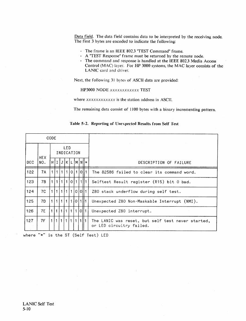
Data field. The data field contains data to be interpreted by the receiving node.The first 3 bytes are encoded to indicate the following:
- The frame is an IEEE 802.3 "TEST Command" frame.- A 'TEST Response ll frame must be returned by the remote node.
The command and response is handled at the IEEE 802.3 Media AccessControl (I\1AC) layer. For HP 3000 systems, the MAC layer consists of theLANIC card and driver.
Next, the following 31 bytes of ASCII data are provided:
HP3000 NODE xxxxxxxxxxxx TEST
where xxxxxxxxxxxx is the station address in ASCII.
The remaining data consist of 1100 bytes with a binary incrementing pattern.
Table 5-2. Reporting of UneXIJected Results from Self Test
CODE
LEDINDICATION
HEXDEC NO. H I J K L M N * DESCRIPTION OF FAILURE
122 7A 1 1 1 1 o 1 o 1 The 82586 failed to clear its command word.
123 78 1 1 1 1 o 1 1 1 Selftest Result register (R15) bit 0 bad.
124 7C 1 1 1 1 1 0 0 1 Z80 stack underflow during self test.
125 7D 1 1 1 1 1 o 1 1 Unexpected Z80 Non-Maskable Interrupt (NMI).
126 7E 1 1 1 1 1 1 0 1 Unexpected Z80 interrupt.
127 7F 1 1 1 1 1 1 1 1 The LANIC was reset, but self test never started,or LED circuitry failed.
where "*" is the ST (Self Test) LED
LANIC Self Test5-10
Tracing
General Information
6
The CS/3000 Trace Facility is used to provide a record of the line actions, CSstates and events that occur during Network Services operation. When problemsoccur during operation, the trace facility provides the means to pinpoint theproblem area. For example, suppose you are experiencing a data integrityproblem between two computers in your network; the information that you sendto one computer isn't the same information that is being received at the otherend. A trace could be enabled to monitor the data in your subsystem to try to"trap" the data transfer error when it occurs.
The trace facility is invoked by the operator with a : LIN KCONTROL command.Tracing can be enabled/disabled when OPENing the line, or before or after theline is opened. Tracing can be invoked for any communication line thatNetwork Services uses. Once invoked for a particular communications line, thetrace facility continues to record line activity until the user issues a new: LINKCONTROL command with the TRACE=OFF parameter. The trace facilitykeeps track of actions, states and events in the form of trace entries.
The trace entries are grouped into trace records: one trace record for each CSintrinsic called by Network Services. The trace records are permanently stored ina system-generated file named LI NKTxxx, or in a user-specified trace file. Thecontents of a CSj3000 trace file can be formatted and printed through the use ofa trace dump utility program. There are two link level trace formattingprograms for Network Services: CSDUMP and DSDUMP. CSDUMP does someformatting and displays all trace file data in a raw form. DSDUMP allows youto choose a subset of the trace file to be formatted, and will also analyze thechosen data. In addition, CSDUMP will display all of the bisynchronous lineprotocol, while DSDUMP only displays the DS protocol. The trace facility mustbe terminated before CSDUMP and DSDUMP can be run. Refer to theFundamental Data Communications Handbook for additional information on theCSTRACE.
Tracing6-1
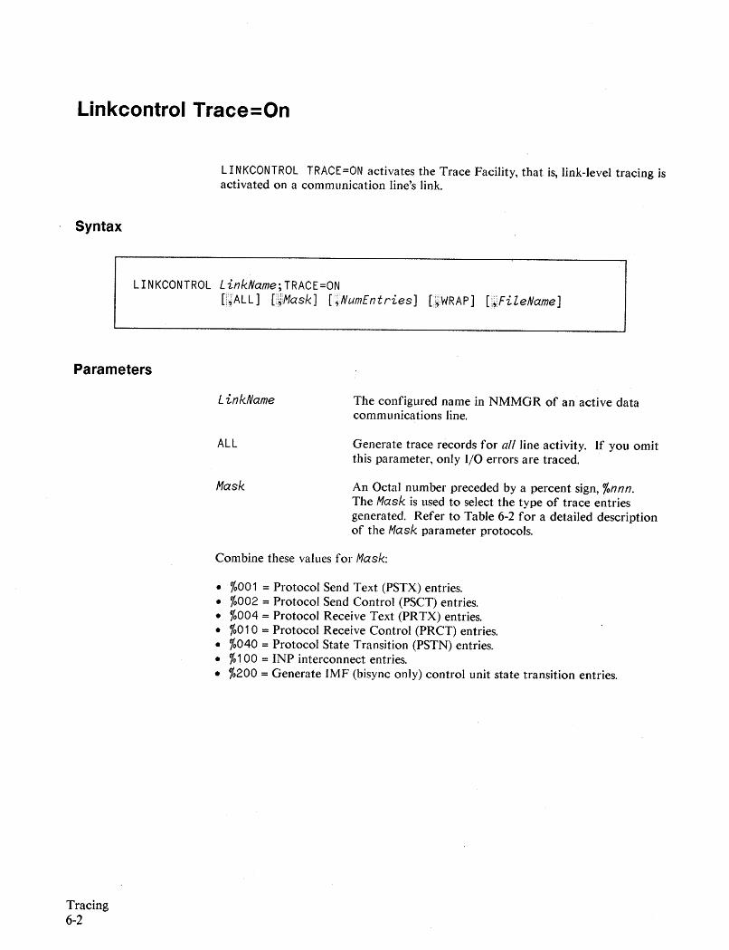
Linkcontrol Trace=On
LI NKCONTROl TRACE=ON activates the Trace Facility, that is, link-level tracing isactivated on a communication line's link.
Syntax
LINKCONTROL LinkName;TRACE=ONmAll] [@Mask] L;NumEntries] [".;WRAP] [".~FileName]
Parameters
LinkName
ALL
Mask
The configured name in NMMGR of an active datacommunications line.
Generate trace records for all line activity. If you omitthis parameter, only I/O errors are traced.
An Octal number preceded by a percent sign, %nnn.The Mask is used to select the type of trace entriesgenerated. Refer to Table 6-2 for a detailed descriptionof the Mask parameter protocols.
Tracing6-2
Combine these values for Mask:
• %001 = Protocol Send Text (PSTX) entries.• %002 = Protocol Send Control (PSCT) entries.• %004 = Protocol Receive Text (PRTX) entries.• %010 = Protocol Receive Control (PRCT) entries.• %040 = Protocol State Transition (PSTN) entries.• %100 = INP interconnect entries.• %200 =Generate IMF (bisync only) control unit state transition entries.
Discussion
numentries
WRAP
filename
The value of entries is used to derive the size of trace
file record. Trace entries are deposited in a record in a
circular manner. A driver dependent default of 24 will
be used if the parameter is omitted. Default = 24.
Specifies that if the trace record is full for a givenCS
intrinsic, previous entries are overlayed. Its absence
indicates that succeeding entries will be flushed. This
parameter does not affect the EOF marker of the file.
Trace output will be sent to a specified file name which
has been previously built. If a file name is not specified,
the default destination will be LIN KTnnn, where nnn is
the MPE logical number of the CS device. If a trace
file exists, it will be purged and a new trace file will be
created.
Example
Refer to NS3000/V Network Manager Reference Manual (32344-90002).
:LINKCONTROL NEWYORK;TRACE=ON,ALL,,24,WRAP,NYCOOO
Link level tracing is activated for the NEWYORK CS device. Records of all line
activity and all trace entries, except for PSTN are generated and sent to file
NYCOOO in the logon group and account. Each trace record has no more than 24
entries. Overflow entries overlay prior trace entries.
Tracing6-3
Linkcontrol Trace=Off
LI NKCONTROL TRACE=OFF deactivates the Trace Facility.
Syntax
LINKCONTROL LinkName;TRACE=OFF
Parameters
Discussion
LinkName The configured name of an active data communicationsline.
Example
Tracing6-4
This command deactivates link level tracing on the specified communicationsline. The link must have been started before you can issue this command.LinkName is NMMGR configuration, not sysdump.
:LINKCONTROL NEWYORK; TRACE=OFF
Link level tracing is deactivated for the NEWYORK LANIC.
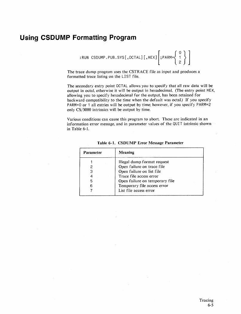
Using CSDUMP Formatting Program
:RUN CSDUMP.PUB.SYS[,OCTAL] [,HEXJ[;PARM={!} ]
The trace dump program uses the CSTRACE file as input and produces aformatted trace listing on the LIST file.
The secondary entry point OCTAL allows you to specify that aU raw data will beoutput in octal, otherwise it will be output in hexadecimal. (The entry point HEX,allowing you to specify hexadecimal for the output, has been retained forbackward compatibility to the time when the default was octal.) If you specifyPARM=O or 1 all entries will be output by time; however, if you specify PARM=2only CSj3000 intrinsics will be output by time.
Various conditions can cause this program to abort. These are indicated in aninformation error message, and in parameter values of the QUI T intrinsic shownin Table 6-1.
Table 6-1. CSDUMP Error Message Parameter
Parameter Meaning
1 Illegal dump format request2 Open failure on trace file3 Open failure on list file4 Trace file access error5 Open failure on temporary file6 Temporary file access error7 List file access error
Tracing6-5

Defining a Trace File for CSDUMP
The program expects a trace file named CSTRACE. If your trace file has adifferent name, such as the default file name LINKTnnn, you will need to equatethe trace file name to CS TRAC E. Use the MPE : FI LE command this way:
:FILE CSTRACE=LINKTnnn.PUB.SYS
Defining a CSDUMP Listing File
The formal file designator of the trace listing file for CSDUMP is LIST. The filemay be defined as a CRT terminal, a line printer, or a disc file. To define the listfile, enter an MPE : FI LE command prior to initiating the CSDUMP program.Some typical examples are:
:FILE LIST;DEV=LP
:FILE LIST=FILENAME
LP is assumed to be the device class name for oneor more line printers.
FI LENAME is assumed to be the name of an oldtemporary or permanent disc file.
If a list file does not exist or is not designated by a : FI LE command, and PARMof the RUN command is not 1, the CSDUMP program employs the user'ssession/job output device as the Jist file. If PARM is set to 1, then the dumpprogram attempts to open the file LIST as an old job or system file. If this failsbecause LIST does not exist, then LIST is opened as a new file in the systemdomain. After the CSDUMP program has run, the contents of this file may beaccessed via a text editor, such as EDIT/3000.
Tracing6-6
Initiation the CSDUMP Program
After the CSTRACE and LIST files have been defined, enter the followingcommand:
:RUN CSDUMPoPUSoSYS[,OCTAL] [;PARM={!}J
The trace dump program uses the CSTRACE file as input and produces aformatted trace listing on the LIST file. The format of the trace listing isdescribed in the following text. If the secondary entry point OCTAL is specifiedwhen CSDUMP is run, the numeric codes for both control characters and datawill be printed in octal instead of hexadecimal. If you specify PARM=O or 1, allentries will be output by time; however, if you specify PARM=2 only CS/3000intrinsics will be output by time.
Formatted CSDUMP Trace Listing
A CSDUMP Trace listing has a specific format. The components of a Tracelisting are a header message; the beginning-of-trace message; the opening LineInformation Display box; a series of trace records, each consisting of a recordheader and one or more consecutively numbered entries; an end-of-trace message;and the closing Line Information Display box. These components are discussedin detail on the following pages. The examples of the various components aretaken from a trace of a line connected to a LANIC.
Tracing6-7
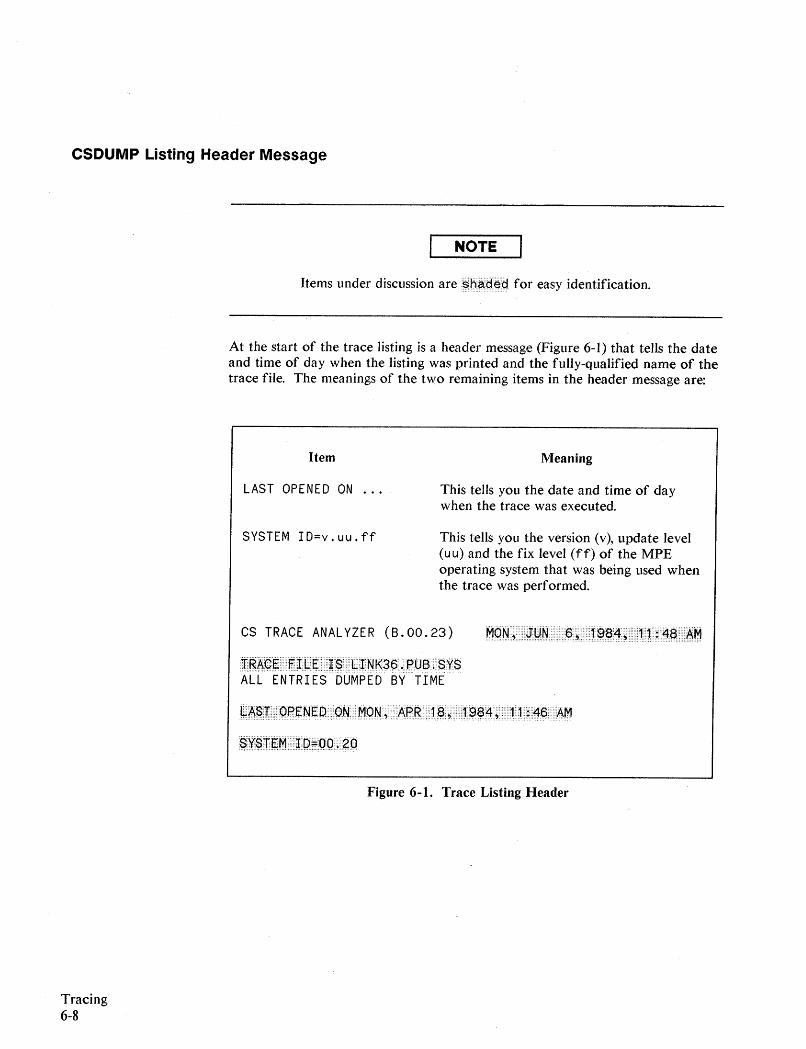
CSDUMP Listing Header Message
NOTE
Items under discussion are~b~(;J~g for easy identification.
At the start of the trace listing is a header message (Figure 6-1) that tells the dateand time of day when the listing was printed and the fully-qualified name of thetrace file. The meanings of the two remaining items in the header message are:
Item
LAST OPENED ON
SYSTEM ID=v.uu.ff
Meaning
This tells you the date and time of daywhen the trace was executed.
This tells you the version (v), update level(u u) and the fix level (ff) of the MPEoperating system that was being used whenthe trace was performed.
CS TRACE ANALYZER (B.00.23)
j"gA~~·.···IT.IL.~··••··~.$··.··L·INk$6 •.·.g0B •.•.SY$ALL ENTRIES DUMPED BY TIME
MqN••~ ••••··i1:gN•••• ···R.·~.·· ••·1·~§4.~·· •••·1·1•• ;·.'7~· ..·.t\r1
~A~fl'· •••·qg~N.~o.·.·qN •••••MqN.;·· APR•••••1.e., ·.··1.S)e4.~.···.·.1 ••1·.i..4p•••••~M
$~~±~M.··.·~DFQQ •.•• gO
Figure 6-1. Trace Listing Header
Tracing6-8
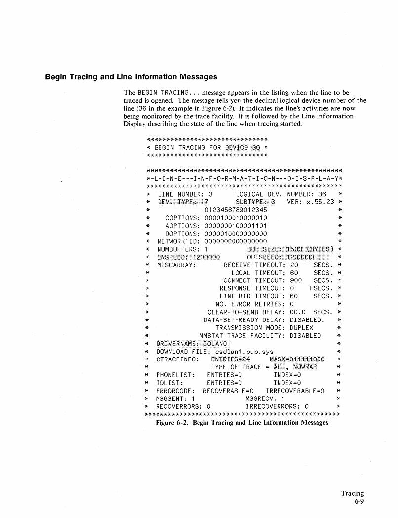
Begin Tracing and Line Information Messages
The BEGI N TRACI NG ... message appears in the listing when the line to betraced is opened. The message tells you the decimal logical device number of theline (36 in the example in Figure 6-2). It indicates the line's activities are nowbeing monitored by the trace facility. It is followed by the Line InformationDisplay describing the state of the line when tracing started.
~******************************
* BEGIN TRACING FOR DEVICE 36 ********************************
***************************************************-L-I-N-E---I-N-F-O-R-M-A-T-I-O-N---D-I-S-P-L-A-Y**************************************************** LINE NUMBER: 3 LOGICAL DEV. NUMBER: 36 **$Q~"t~A~;n$ VER: x.55.23 ** 0123456789012345 ** COPTIONS: 0000100010000010 ** AOPTIONS: 0000000100001101 ** DOPTIONS: 0000010000000000 ** NETWORK'ID: 0000000000000000 ** NUMBUF FERS: [email protected]§I.4FUt l$OOn(~~m~$) ** :IN$p~qE:DiT120()00Q oUTsP~gD~ 1200000 ** MISCARRAY: RECEIVE TIMEOUT: 20 SECS. ** LOCAL TIMEOUT: 60 SECS. ** CONNECT TIMEOUT: 900 SECS. ** RESPONSE TIMEOUT: 0 HSECS. ** LINE BID TIMEOUT: 60 SECS. ** NO. ERROR RETRIES: 0 ** CLEAR-TO-SEND DELAY: 00.0 SECS. ** DATA-SET-READY DELAY: DISABLED. ** TRANSMISSION MODE: DUPLEX ** MMSTAT TRACE FACILITY: DISABLED **P.RI.VERNAM~:1~I..ANO ** DOWNLOAD FILE: csdlan1.pub.sys ** CTRACEINFO: ENTRIES~24 MA$~~P1111~~~0 ** TYPE OF TRACE~lliU,~PW~~A ** PHONELIST: ENTRIES=O INDEX=O ** IDLIST: ENTRIES=O INDEX=O ** ERRORCODE: RECOVERABLE=O IRRECOVERABLE=O ** MSGSENT: 1 MSGRECV: 1 ** RECOVERRORS: 0 IRRECOVERRORS: 0 ***************************************************
Figure 6-2. Begin Tracing and Line Information Messages
Tracing6-9
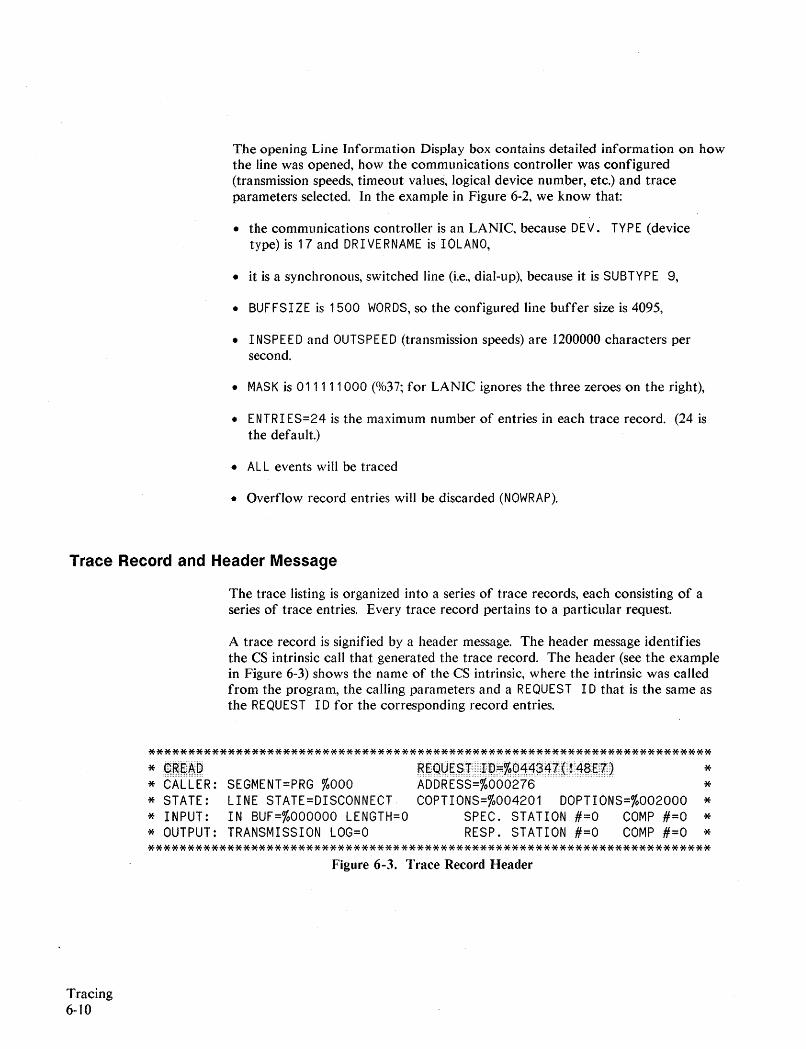
The opening Line Information Display box contains detailed information on howthe line was opened, how the communications controller was configured(transmission speeds, timeout values, logical device number, etc.) and traceparameters selected. In the example in Figure 6-2, we know that:
• the communications controller is an LANIC, because DEV. TYPE (devicetype) is 17 and DRIVERNAME is IOLANO,
• it is a synchronous, switched line (i.e., dial-up), because it is SUBTYPE 9,
• BUFFSIZE is 1500 WORDS, so the configured line buffer size is 4095,
• I NSPEED and OUTSPEED (transmission speeds) are 1200000 characters persecond.
• MASK is 011111000 (%37; for LANIC ignores the three zeroes on the right),
• ENTRIES=24 is the maximum number of entries in each trace record. (24 isthe default.)
• AL L events will be traced
• Overflow record entries will be discarded (NOWRAP).
Trace Record and Header Message
The trace listing is organized into a series of trace records, each consisting of aseries of trace entries. Every trace record pertains to a particular request.
A trace record is signified by a header message. The header message identifiesthe CS intrinsic call that generated the trace record. The header (see the examplein Figure 6-3) shows the name of the CS intrinsic, where the intrinsic was calledfrom the program, the calling parameters and a REQUEST I Dthat is the same asthe REQUEST I Dfor the corresponding record entries.
************************************************************************ ~:~·e'A·~
* CALLER:* STATE:* INPUT:* OUTPUT:
SEGMENT=PRG %000LINE STATE=DISCONNECTIN BUF=%OOOOOO LENGTH=OTRANSMISSION LOG=O
ggQQe$i ••··.mD:::%Q't.4;34Z.{·Y.4$E.f.).~bb~t§§~%riri6~j~~~~- .~~ .COPTIONS=%004201 DOPTIONS=%002000
SPEC. STATION #=0 COMP #=0RESP. STATION #=0 COMP #=0
*****
***********************************************************************Figure 6-3. Trace Record Header
Tracing6-10
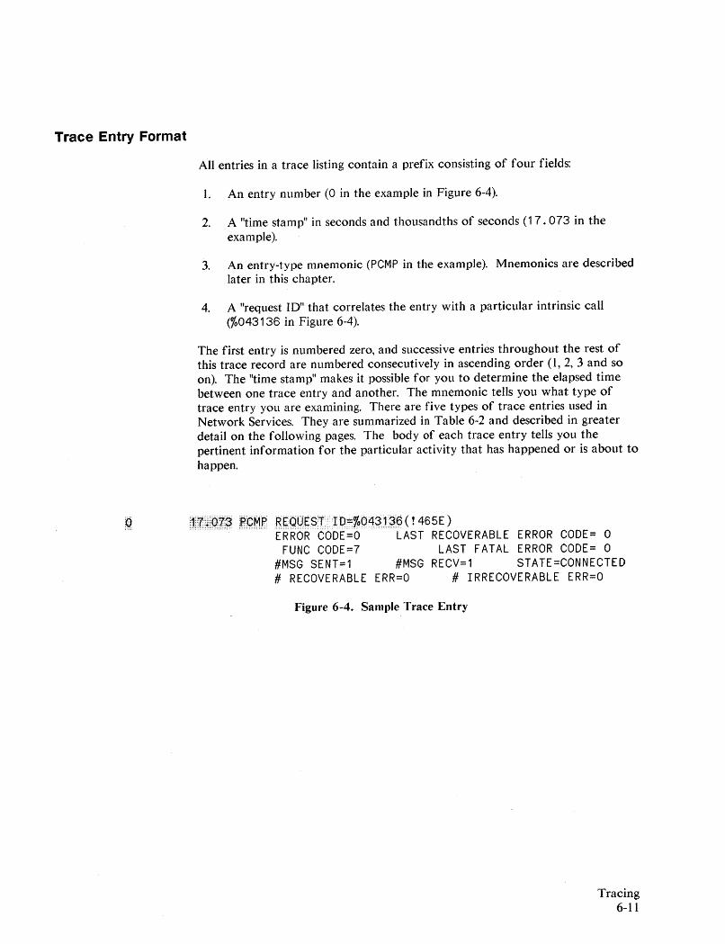
Trace Entry Format
All entries in a trace listing contain a prefix consisting of four fields:
1. An entry number (0 in the example in Figure 6-4).
2. A "time stamp" in seconds and thousandths of seconds (17.073 in theexample).
3. An entry-type mnemonic (PCMP in the example). Mnemonics are describedlater in this chapter.
4. A "request ID" that correlates the entry with a particular intrinsic call(%043136 in Figure 6-4).
The first entry is numbered zero, and successive entries throughout the rest ofthis trace record are numbered consecutively in ascending order (1, 2, 3 and soon). The "time stamp" makes it possible for you to determine the elapsed timebetween one trace entry and another. The mnemonic tells you what type oftrace entry you are examining. There are five types of trace entries used inNetwork Services. They are summarized in Table 6-2 and described in greaterdetail on the following pages. The body of each trace entry tells you thepertinent information for the particular activity that has happened or is about tohappen.
~~''t-· •..P't-~~~M~ RsqqS§JJPrr%P4?t$p (! 465E)ERROR CODE=O LAST RECOVERABLE ERROR CODE= 0
FUNC CODE=7 LAST FATAL ERROR CODE= 0#MSG SENT=1 #MSG RECV=1 STATE=CONNECTED# RECOVERABLE ERR=O # IRRECOVERABLE ERR=O
Figure 6-4. Sample Trace Entry
Tracing6-11
Missing Entries Message
If MISSING ENTRIES appears in the listing, it means that the record was notlarge enough to accommodate all of the trace entries and some entries were lost.If WRAP was not specified (NOWRAP), then the missing entries were at the end justbefore the PCMP entry; otherwise they are missing from the beginning wherethey were overlaid by the trace entries that extended past the end of the record.If the missing entries are crucial:
1. Purge the trace file.
2. Invoke trace again, issuing: LI NKCONTROL with
a. a larger numentries value
b. a mask setting that will produce only those trace entries you are reallyinterested in.
Trace Entry Mnemonics
There are five types of trace entries created by the LANIC driver. There are noconflicts with NMS tracing. A received frame will generate the followingsequence of entries which are summarized in Table 6-2 and described in greaterdetail on the pages following this table.
Tracing6-12
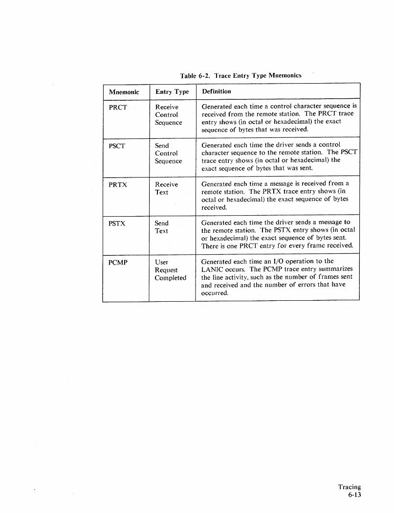
Table 6-2. Trace Entry Type Mnemonics
Mnemonic
PRCT
PSCT
PRTX
PSTX
PCMP
Entry Type
ReceiveControlSequence
SendControlSequence
ReceiveText
SendText
UserRequestCompleted
Definition
Generated each time a control character sequence isreceived from the remote station. The PRCT traceentry shows (in octal or hexadecimal) the exactsequence of bytes that was received.
Generated each time the driver sends a controlcharacter sequence to the remote station. The PSCTtrace entry shows (in octal or hexadecimal) theexact sequence of bytes that was sent.
Generated each time a message is received from aremote station. The PRTX trace entry shows (inoctal or hexadecimal) the exact sequence of bytesreceived.
Generated each time the driver sends a message tothe remote station. The PSTX entry shows (in octalor hexadecimal) the exact sequence of bytes sent.There is one PRCT entry for every frame received.
Generated each time an I/O operation to theLANIC occurs. The PCMP trace entry summarizesthe line activity, such as the number of frames sentand received and the number of errors that haveoccurred.
Tracing6-13
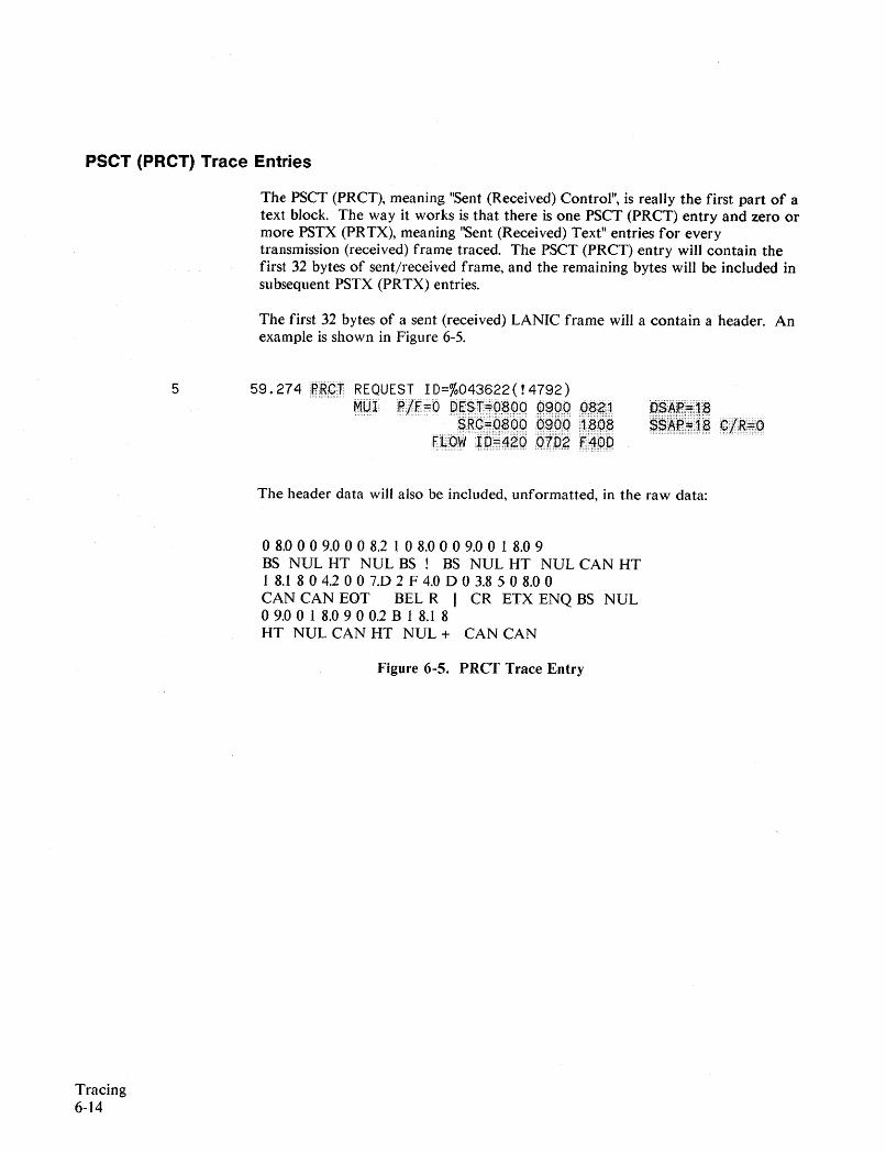
PSCT (PRCT) Trace Entries
The PSCT (PRCT), meaning "Sent (Received) Control", is really the first part of atext block. The way it works is that there is one PSCT (PRCT) entry and zero ormore PSTX (PRTX), meaning "Sent (Received) Text" entries for everytransmission (received) frame traced. The PSCT (PRCT) entry will contain thefirst 32 bytes of sent/received frame, and the remaining bytes will be included insubsequent PSTX (PRTX) entries.
The first 32 bytes of a sent (received) LANIC frame will a contain a header. Anexample is shown in Figure 6-5.
5 59.274 18¢~ REQUEST 10=%043622(!4792)...... MlnplF'~bP~§m~~~~qg~g.~q~gj
~~~~q~ppg~qq~~~~F"~(:)W~P:ffi4~~QnP~r4dO
.~~~i~i7j~:~ .~~~~rr·1.~ B/Rs·q
Tracing6-14
The header data will also be included, unformatted, in the raw data:
o8.0 0 0 9.0 0 0 8.2 I 0 8.0 0 0 9.0 0 1 8.0 9BS NUL HT NUL BS ! BS NUL HT NUL CAN HT1 8.1 8 0 4.2 0 0 7.D 2 F 4.0 D 0 3.8 5 0 8.0 0CAN CAN EOT BEL R I CR ETX ENQ BS NULo9.0 0 1 8.0 9 0 0.2 B 1 8.1 8HT NUL CAN HT NUL + CAN CAN
Figure 6-5. PRCT Trace Entry
The meaning of the various items are as follows:
MU1
P/F
OEST
OSAP
SRC
SSAP
C/R
FLOW 10
Mode-independent Unnumbered Information (frame type),other options are XID (exchange Identity), TEST (test), and !xx(undecodable).
Poll/Final bit (0 or 1).
This the destination address.
Destination Service Access Point points to the proper protocolthe next higher level.
This is the source address.
Source Service Access Point points from the proper protocolof the next higher level.
Command =0 and Response = 1.
This is a unique 48-bit quantity that is not used presently.
Note that, in order to facilitate tracing, the format of the 32 byte header doesnot coincide with the data actually sent or received on the wire. The LANICdriver header contains data that allows the dump reader to match the link-leveltrace entries with higher level trace entries. The formats are provided on thenext page.
Tracing6-15
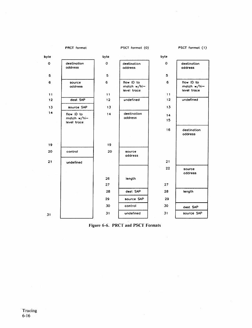
byte
o
5
6
11
12
13
14
19
20
21
31
PRCT format
destinationaddress
sourceaddress
dest SAP
source SAP
flow 10 tomatch w/hi-level trace
control
undefined
byte
o
5
6
11
12
13
14
19
20
26
27
28
29
30
31
PSCT format (0)
destinationaddress
flow 10 tomatch w/hi-level trace
undefined
destinationaddress
sourceaddress
length
dest SAP
source SAP
control
undefined
byte
o
5
6
11
12
13
14
15
16
21
22
27
28
29
30
31
PSCT format (1)
destinationaddress
flow 10 tomatch w/hi-level trace
undefined
destinationaddress
sourceaddress
length
dest SAP
source SAP
.Tracing6-16
Figure 6-6. PRCT and PSCT Formats
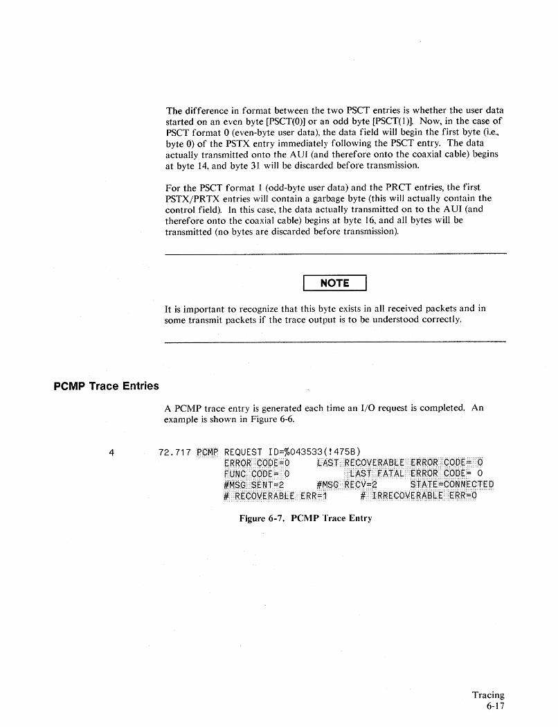
The difference in format between the two PSCT entries is whether the user datastarted on an even byte [PSCT(O)] or an odd byte [PSCT( I )]. Now, in the case ofPSCT format 0 (even-byte user data), the data field will begin the first byte (i.e.,byte 0) of the PSTX entry immediately following the PSCT entry. The dataactually transmitted onto the AVI (and therefore onto the coaxial cable) beginsat byte 14, and byte 31 will be discarded before transmission.
For the PSCT format I (odd-byte user data) and the PRCT entries, the firstPSTX/PRTX entries will contain a garbage byte (this will actually contain thecontrol field). In this case, the data actually transmitted on to the AVI (andtherefore onto the coaxial cable) begins at byte 16, and all bytes will betransmitted (no bytes are discarded before transmission).
NOTE
It is important to recognize that this byte exists in all received packets and insome transmit packets if the trace output is to be understood correctly.
PCMP Trace Entries
A PCMP trace entry is generated each time an I/O request is completed. Anexample is shown in Figure 6-6.
4 72.717 I¢MB REQUEST ID=%043533(!475B)P.~~~~.· ..·(]QDEE.~ lliA$T.·••·~e~qVs.~AS:t.~. ..~.·~g(j)g •••··~qpg::: ••·••.OFRNP90PE=QO ·... 4~$,.LFAIAL P~R~R~QPs== 0~M8~§ENTJ'g #MSG·RECYs6 $"~"f:FCONNECIED#RECbvERABlliE ERR±:1 #.LIggEC;:~Y:~~Aal.~ E~~::=O
Figure 6-7. PCMP Trace Entry
Tracing6-17
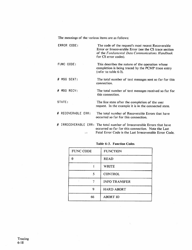
The meanings of the various items are as follows:
ERROR CODE:
FUNC CODE:
# MSG SENT:
# MSG RECV:
STATE:
# RECOVERABLE ERR:
The code of the request's most recent RecoverableError or Irrecoverable Error (see the CS trace sectionof the Fundamental Data Communications Handbookfor CS error codes).
This describes the nature of the operation whosecompletion is being traced by the PCMP trace entry(refer to table 6-3).
The total number of text messages sent so far for thisconnection.
The total number of text messages received so far forthis connection.
The line state after the completion of the userrequest. In the example it is in the connected state.
The total number of Recoverable Errors that haveoccurred so far for this connection.
Tracing6-18
# I RRECOVERABLE ERR: The total number of Irrecoverable Errors that haveoccurred so far for this connection. Note the LastFatal Error Code is the Last Irrecoverable Error Code.
Table 6-3. Function Codes
FUNC CODE FUNCTION
0 READ
I WRITE
5 CONTROL
7 INFO TRANSFER
9 HARD ABORT
66 ABORT 10
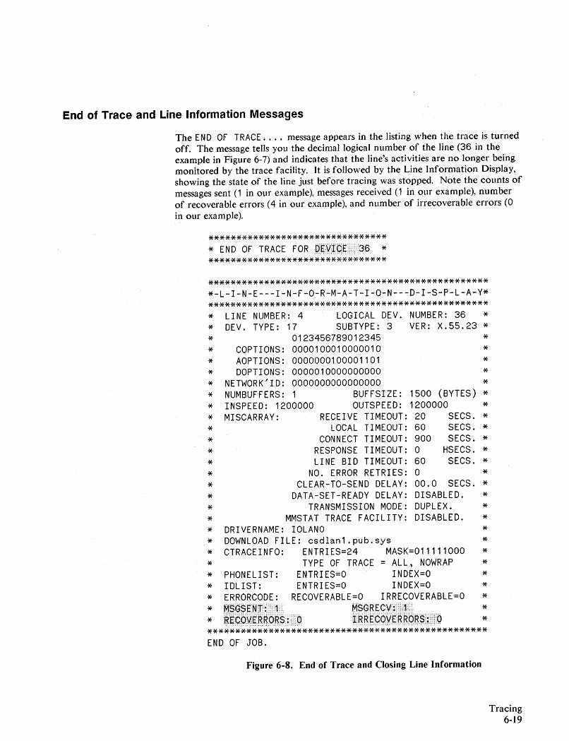
End of Trace and Line Information Messages
The END OF TRACE .... message appears in the listing when the trace is turnedoff. The message tells you the decimal logical number of the line (36 in theexample in Figure 6-7) and indicates that the line's activities are no longer beingmonitored by the trace facility. It is followed by the Line Information Display,showing the state of the line just before tracing was stopped. Note the counts ofmessages sent (1 in our example), messages received (1 in our example), numberof recoverable errors (4 in our example), and number of irrecoverable errors (0in our example).
********************************* END OF TRACE FORD~~~(:)E L36 *********************************
***************************************************-l-I-N-E---I-N-F-O-R-M-A-T-I-O-N---D-I-S-P-l-A-Y**************************************************** lINE NUMBER: 4 lOGICAL DEV. NUMBER: 36 ** DEV. TYPE: 17 SUBTYPE: 3 VER: X.55.23 ** 0123456789012345 ** COPTIONS: 0000100010000010 ** AOPTIONS: 0000000100001101 ** DOPTIONS: 0000010000000000 ** NETWORK'ID: 0000000000000000 ** NUMBUfFERS: 1 BUFFSIZE: 1500 (BYTES) ** INSPEED: 1200000 OUTSPEED: 1200000 ** MISCARRAY: RECEIVE TIMEOUT: 20 SECS. ** lOCAL TIMEOUT: 60 SECS. ** CONNECT TIMEOUT: 900 SECS. ** RESPONSE TIMEOUT: 0 HSECS. ** lINE BID TIMEOUT: 60 SECS. ** NO. ERROR RETRIES: 0 ** CLEAR-TO-SEND DELAY: 00.0 SECS. ** DATA-SET-READY DELAY: DISABLED. ** TRANSMISSION MODE: DUPLEX. ** MMSTAT TRACE FACILITY: DISABLED. ** DRIVERNAME: IOlANO ** DOWNLOAD FILE: csdlan1.pub.sys ** CTRACEINFO: ENTRIES=24 MASK=011111000 ** TYPE OF TRACE = ALL, NOWRAP ** PHONELIST: ENTRIES=O INDEX=O ** IDlIST: ENTRIES=O INDEX=O ** ERRORCODE: RECOVERABLE=O IRRECOVERABLE=O ** M~~$R~m:~ M$~~RY~:.:1, **~~G~~e~~~~$:.Q1~~E¢~\l~~~~~$·~U:Q ***************************************************END OF JOB.
Figure 6-8. End of Trace and Closing Line Information
Tracing6-19
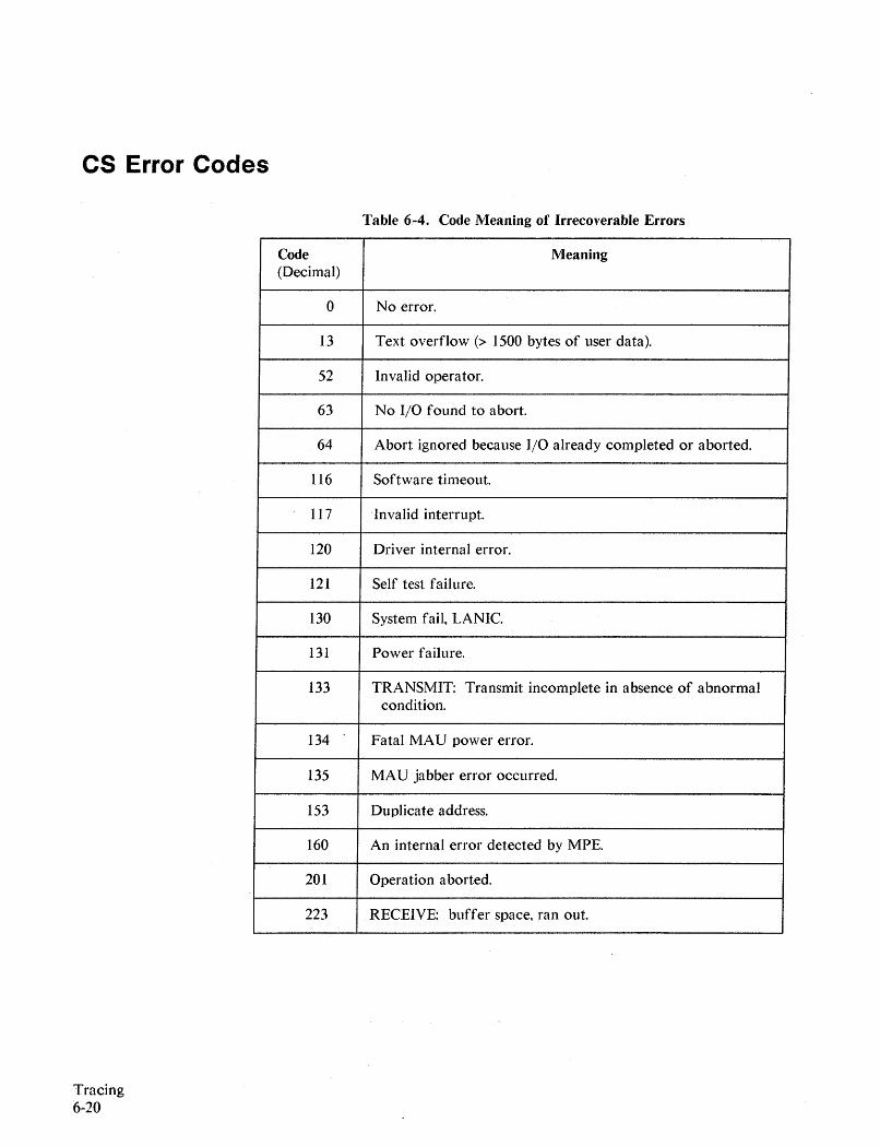
CS Error Codes
Table 6-4. Code Meaning of Irrecoverable Errors
Tracing6·20
Code Meaning(Decimal)
0 No error.
13 Text overflow (> 1500 bytes of user data).
52 Invalid operator.
63 No I/O found to abort.
64 Abort ignored because I/O already completed or aborted.
116 Software timeout.
117 Invalid interrupt.
120 Driver internal error.
121 Self test failure.
130 System fail, LANIC.
131 Power failure.
133 TRANSMIT: Transmit incomplete in absence of abnormalcondition.
134 Fatal MAU power error.
135 MAU jabber error occurred.
153 Duplicate address.
160 An internal error detected by MPE.
201 Operation aborted.
223 RECEIVE: buffer space, ran out.
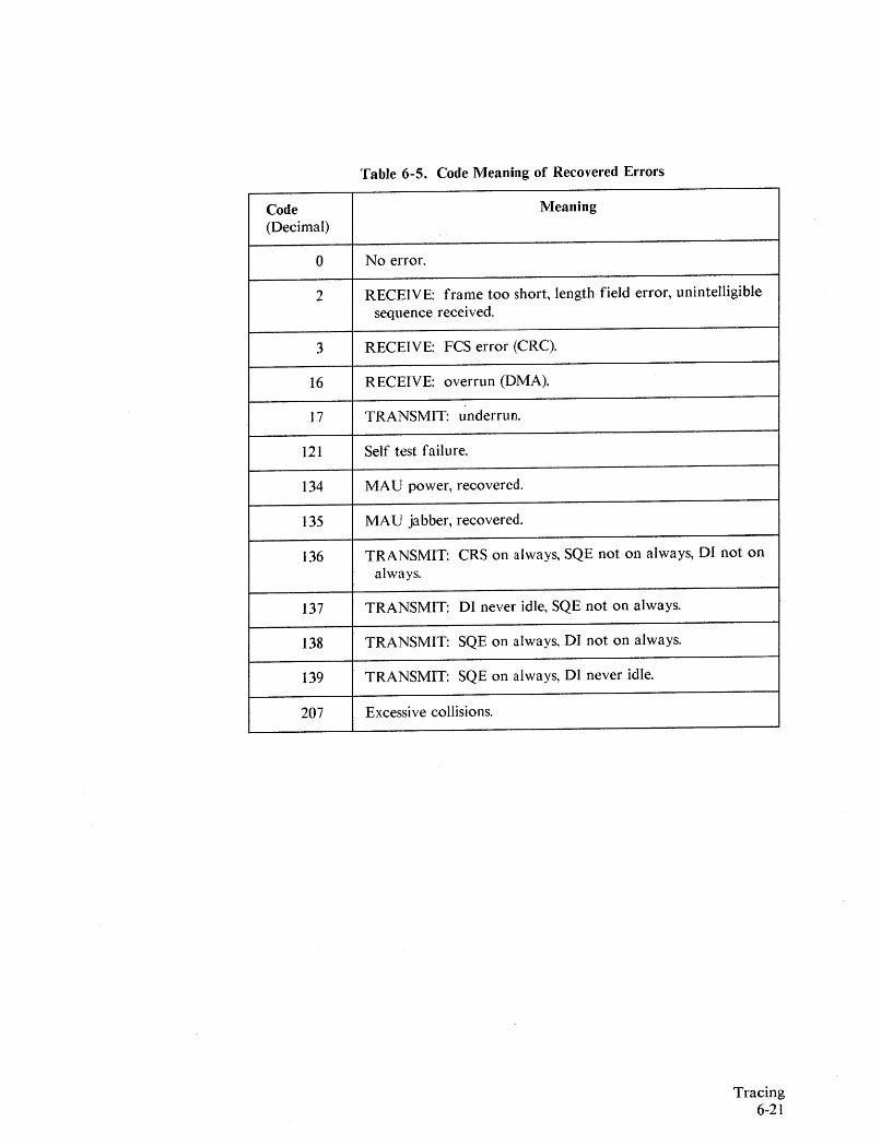
Table 6-5. Code Meaning of Recovered Errors
Code Meaning(Decimal)
0 No error.
2 RECEIVE: frame too short, length field error, unintelligiblesequence received.
3 RECEIVE: FCS error (CRC).
16 RECEIVE: overrun (DMA).
17 TRANSMIT: underrun.
121 Self test failure.
134 MAU power, recovered.
135 MAU jabber, recovered.
136 TRANSMIT: CRS on always, SQE not on always, DI not onalways.
137 TRANSMIT: DI never idle, SQE not on always.
138 TRANSMIT: SQE on always, DI not on always.
139 TRANSMIT: SQE on always, DI never idle.
207 Excessive collisions.
Tracing6-21


Software Tools
Memory Dump
When a SYSFAIL or some other severe condition occurs, refer to the M PE VSystem Operation and Resource Management Relerence Manual (32033-90005)for instructions on doinga memory dump.
NSDPAN5/NSDUMPJ
7
The NSDPAN5 pr~gram produces a formatted listing of main memory, based ona memory dump taken after a system failure, HALT, or other abnormalcondition.
Obtaining an NSDPAN5 Listing
1. Immediately after system termination, use the Software Dump Facility(SDF) to make a main memory dump. This facility gives you the capabilityof storing main memory to either a serial disc, cartridge tape, or magnetictape. It operates in a stand-alone environment after a system failure hasoccurred or a system halt has been performed. The SDF is described in theM PE V System Operation and Resource Management Relerence Manual(32033-90005).
2. When the system has been restarted, enter the command:
:STREAM NSDUMPJ.NET.SYS
This version of NSDPAN5 has several advantages:
• It is customized to show NS data structures.
• It saves virtual memory
• If the problem is in another product, this dump still applies.
Software Tools7-1
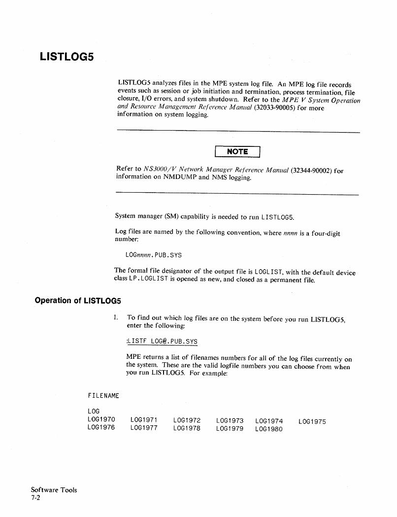
LISTLOG5
LISTLOG5 analyzes files in the MPE system log file. An MPE log file recordsevents such as session or job initiation and termination, process termination, fileclosure, I/O errors, and system shutdown. Refer to the M PE V System Operationand Resource Management Reference Manual (32033-90005) for moreinformation on system logging.
NOTE
Refer to NS3000/V Network Manager Reference Manual (32344-90002) forinformation on NMDUMP and NMS logging.
System manager (SM) capability is needed to run LISTLOG5.
Log files are named by the following convention, where nnnn is a four-digitnumber:
LOGnnnn.PUB.SYS
The formal file designator of the output file is LOGLIST, with the default deviceclass LP. LOGLIST is opened as new, and closed as a permanent file.
Operation of LISTLOG5
1. To find out which log files are on the system before you run LISTLOG5,enter the following:
:LISTF [email protected]
MPE returns a list of filenames numbers for all of the log files currently onthe system. These are the valid logfile numbers you can choose from whenyou run LISTLOG5. For example:
FILENAME
Software Tools7-2
LOGLOG1970LOG1976
LOG1971LOG1977
LOG1972LOG1978
LOG1973LOG1979
LOG1974LOG1980
LOG1975
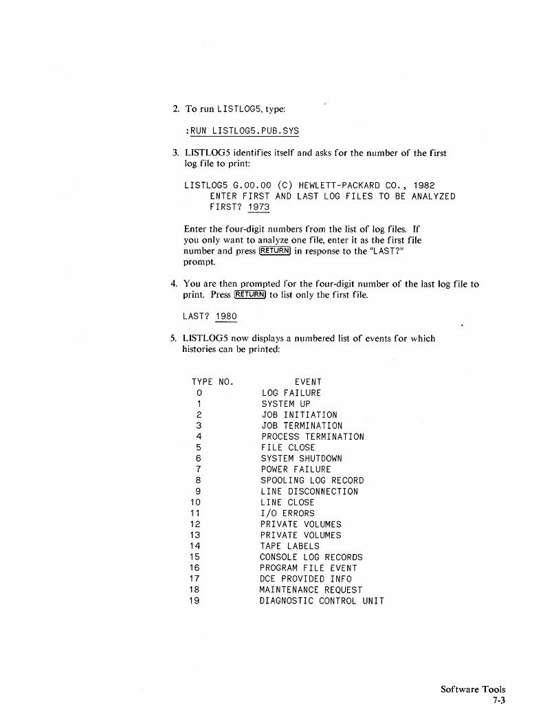
2. To run LISTLOG5, type:
:RUN LISTLOG5.PUB.SYS
3. LISTLOG5 identifies itself and asks for the number of the firstlog file to print:
LISTLOG5 G.OO.OO (C) HEWLETT-PACKARD CO., 1982ENTER FIRST AND LAST LOG FILES TO BE ANALYZEDFIRST? 1973
Enter the four-digit numbers from the list of log files. Ifyou only want to analyze one file, enter it as the first filenumber and press [RETURN) in response to the "LAST?"prompt.
4. You are then prompted for the four-digit number of the last log file toprint. Press [RETURN) to list only the first file.
LAST? 1980
5. LISTLOG5 now displays a numbered list of events for whichhistories can be printed:
TYPE NO.o123456789
10111213141516171819
EVENTLOG FAILURESYSTEM UPJOB INITIATIONJOB TERMINATIONPROCESS TERMINATIONFILE CLOSESYSTEM SHUTDOWNPOWER FAILURESPOOLING LOG RECORDLINE DISCONNECTIONLINE CLOSEI/O ERRORSPRIVATE VOLUMESPRIVATE VOLUMESTAPE LABELSCONSOLE LOG RECORDSPROGRAM FILE EVENTDCE PROVIDED INFOMAINTENANCE REQUESTDIAGNOSTIC CONTROL UNIT
Software Tools7-3
Software Tools7-4
6. At the end "of the list of events, you are prompted for input with themessage:
ENTER EVENT NUMBERS SEPARATED BY COMMAS?A CARRIAGE RETURN ASSUMES ALL EVENTS WILL BE EVALUATED.
Type the event numbers and press [RETURN!. LISTLOG5 creates spool files ofthe events that you requested. There are no messages echoed back to yourterminal if your request is successful. If you request is not successful, one oftwo messages will be displayed: 1) an error message in the format describedunder "ERROR CONDITIONS", or 2) a message indicating that there are noevents for the log file numbers that you requested:
NO DESIRED EVENTS FOUND IN LOGFILE 1980
If events have been found for a log file, it's number will not appear in theNODESIR ED EVE NTS list:
NO DESIRED EVENTS FOUND IN LOGFILE 1978NO DESIRED EVENTS FOUND IN LOGFILE 1979
Events have been found for all other requested log files, so they do notappear in this list.
7. LISTLOG5 then asks:
DO YOU WANT TO PURGE LOG FILES?
If you answer YES, then log files are printed and then purged from thesystem. If you answer NO, the files are printed and also retained by thesystem. You are now asked if you want to return to the program; TypeYES to continue with LOGLIST5, NO or ~ to terminate:
DO YOU WISH TO RUN AGAIN (Y OR N)? ~
NMMAINT
The NM Maintenance Utility (NMMAINT) is a utility program supplied with HP3000 LAN link products as part of the Node Management Services (NMS).NMMAINT is used to display the individual and overall version numbers for thesoftware modules of the data communications products that use the NodeManagement Services (NMS). These products include the NS3000/V, SNA IMF,and SNA NRJE Network Services products as well as the SNA and LAN3000/VNetwork Link products.
NMS defines one or more subsystems for each of the data, communicationsproducts. For the HP3000 LAN link, there are three subsystems defined: theNode Management Services, the Network Transport, and the Link Servicessubsystems. For NS3000/V, there is one subsystem, the Network Services. Eachsoftware module within a subsystem, such as a program file or SL segment, hasits own version 10 number. If the version, update, and fix levels of thesemodules do not match, the subsystem will not work correctly. NMMAINT canbe used to determine if you have an invalid software installation or if thesoftware modules of a subsystem are mismatched. The information provided byNMMAINT should be included in any SR submitted. Refer to the NS3000/VNetwork Manager Relerence Manual.
To run NMMAINT, issue the command:
:RUN NMMAINT.PUB.SYS
NMMAINT will respond with the following:
32099-11018A.01.00 NM Maintenance Utility (C) Hewlett PackardCo. 1985
NMMAINT then lists the version identification numbers for each softwaremodule as well as subsystem information for each subsystem. As shown in theexample below, the NMMAINT utility displays version information for thesubsystems of the products actually installed on your system. The NodeManagement Services, Link Services, and Network Transport subsystems aredisplayed if the HP 3000 LAN link product is installed. The Network Servicessubsystem is displayed if the NS3000/V product is instaIIed. The SNA Transport,NRJE, and IMF subsystems are displayed if the appropriate HP to IBM datacommunications products are instaIIed on your system. The example shows asystem with NS3000/V and the HP 3000 LAN link installed. The subsystems arealways displayed in the same order, which is the Node Management Servicessubsystem first, followed by SNA Transport, NRJE,and IMF, then the NetworkTransport, Network Services, and Link Services subsystems. The last version IDnumber listed is the port software, I PCVERSION. This is not part of theNetworkIPC user service, nor does it form a subsystem as the previous sets, butits individual version ID number is displayed by NMMAINT for yourinformation.
Software Tools7-5
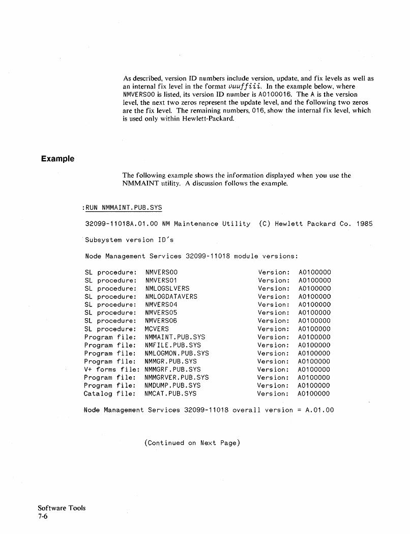
As described, version ID numbers include version, update, and fix levels as well asan internal fix level in the format vuuffiii. In the example below, whereNMVE RSOO is listed, its version ID number is AO 100016. The Ais the versionlevel, the next two zeros represent the update level, and the following two zerosare the fix level. The remaining numbers, 016, show the internal fix level, whichis used only within Hewlett-Packard.
Example
The following example shows the information displayed when you use theNMMAINT utility. A discussion follows the example.
:RUN NMMAINT.PUB.SYS
32099-11018A.01.00 NM Maintenance Utility (C) Hewlett Packard Co. 1985
Subsystem version 1D's
Node Management Services 32099-11018 module versions:
SL procedure: NMVERSOO Version: A0100000SL procedure: NMVERS01 Version: A0100000SL procedure: NMLOGSLVERS Version: A0100000SL procedure: NMLOGDATAVERS Version: A0100000SL procedure: NMVERS04 Version: A0100000SL procedure: NMVERS05 Version: A0100000SL procedure: NMVERS06 Version: A0100000SL procedure: MCVERS Version: A0100000Program fi Ie: NMMA1NT.PUB.SYS Version: A0100000Program file: NMFILE.PUB.SYS Version: A0100000Prog ram f i Ie: NMLOGMON.PUB.SYS Version: A0100000Program fi Ie: NMMGR.PUB.SYS Version: A0100000V+ form s f i 1e : NMMGRF.PUB.SYS Version: A0100000Program file: NMMGRVER.PUB.SYS Version: A0100000Program fi Ie: NMDUMP.PUB.SYS Version: A0100000Catalog file: NMCAT.PUB.SYS Version: A0100000
Node Management Services 32099-11018 overall version = A.01.00
(Continued on Next Page)
Software Tools7-6

Network Transport Module Versions
Program File NETCP.NET.SYS Version: AOOOOOOOProgram File NETSERVE.NET.SYS Version: AOOOOOOOProgram File SOCKREG.NET.SYS Version: AOOOOOOOProgram File NETMSG.NET.SYS Version: AOOOOOOOMessage File NET'SM4'VERS Version: AOOOOOOOSL Procedure NET'UI'VERS Version: AOOOOOOOSL Procedure NET'SL'VERS Version: AOOOOOOOSL Procedure NET'NI'VERS Version: AOOOOOOOSL Procedure NET'PROBE'VERS Version: AOOOOOOOSL Procedure NET'TCPO'VERS Version: AOOOOOOOSL Procedure NET'TCP1'VERS Version: AOOOOOOOSL Procedure NET'PXPO'VERS Version: AOOOOOOOSL Procedure NET'PXP1'VERS Version: AOOOOOOOSL Procedure NET'IP'VERS Version: AOOOOOOOSL Procedure NET'IPU'VERS Version: AOOOOOOOSL Procedure NET'PD'VERS Version: AOOOOOOOSL Procedure SOCKIOVERS Version: AOOOOOOOSL Procedure SOCKACCESSVERS Version: AOOOOOOOSL Procedure SOCKMISC1VERS Version: AOOOOOOOSL Procedure SUBSYS3FMTVERS Version: AOOOOOOO
SL Procedure SUBSYS5FMTVERS Version: AOOOOOOOSL Procedure TRIGVERS ** Not Installed
Network Transport Overall Version A.OO.OO
Network Services HP32344 individual module versions:
SL procedure:SL procedure:SL procedure:SL procedure:SL procedure:SL procedure:SL procedure:SL procedure:SL procedure:SL procedure:Prog ram f i Ie:Program file:Program fi Ie:Prag ram f i Ie:
ASCXVERSASBUFVERSASENVVERSDSUTILVERSASRFAVERSVTSVERS1VTSVERS2ASPTOPVERSASRPMVERSSUBSYS6FMTVERSDSDAD.NET.SYSDSSERVER.NET.SYSIOVTERMO.PUB.SYSNFT.NET.SYS
Vers ion:Version:Vers ion:Version:Version:Version:Vers ion:Version:Version:Version:Version:Vers ion:Version:Version:
AOOOOOOOAOOOOOOOAOOOOOOOAOOOOOOOAOOOOOOOAOOOOOOOAOOOOOOOAOOOOOOOAOOOOOOOAOOOOOOOAOOOOOOOAOOOOOOOAOOOOOOOAOOOOOOO
Network Services HP32344 overall subsystem version: A.OO.OO
Software Tools7-7
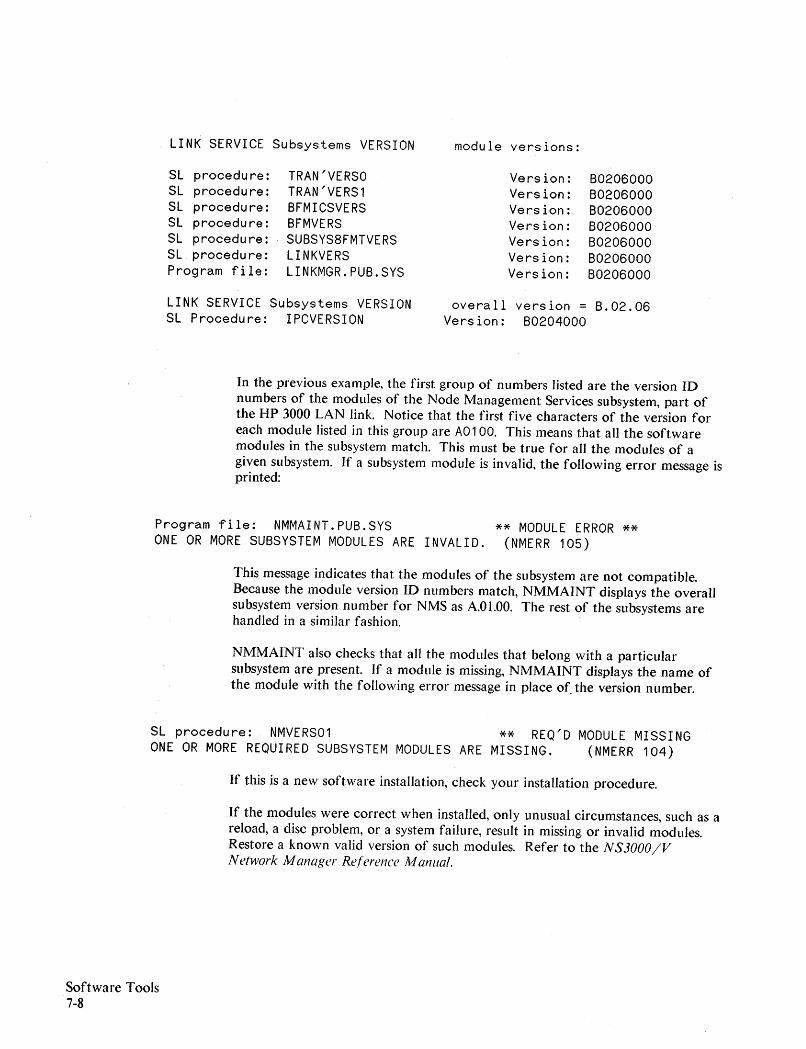
LINK SERVICE Subsystems VERSION module vers ions:
SL procedure: TRAN'VERSO Version: B0206000SL procedure: TRAN'VERS1 Version: B0206000SL procedure: BFMICSVERS Version: B0206000SL procedure: BFMVERS Version: B0206000SL procedure: SUBSYS8FMTVERS Version: B0206000SL procedure: LINKVERS Version: B0206000Program file: LINKMGR.PUB.SYS Version: B0206000
LINK SERVICE Subsystems VERSION overall vers ion = B.02.06SL Procedure: IPCVERSION Version: B0204000
In the previous example, the first group of numbers listed are the version IDnumbers of the modules of the Node Management Services subsystem, part ofthe HP 3000 LAN link. Notice that the first five characters of the version foreach module listed in this group are AO 100. This means that all the softwaremodules in the subsystem match. This must be true for all the modules of agiven subsystem. If a subsystem module is invalid, the following error message isprinted:
Program file: NMMAINT.PUB.SYSONE OR MORE SUBSYSTEM MODULES ARE INVALID.
** MODULE ERROR **(NMERR 105)
This message indicates that the modules of the subsystem are not compatible.Because the module version ID numbers match, NMMAINT displays the overallsubsystem version number for NMS as A.Ol.OO. The rest of the subsystems arehandled in a similar fashion.
NMMAINT also checks that all the modules that belong with a particularsubsystem are present. If a module is missing, NMMAINT displays the name ofthe module with the following error message in place of. the version number.
SL procedure: NMVERS01 ** REQ'D MODULE MISSINGONE OR MORE REQUIRED SUBSYSTEM MODULES ARE MISSING. (NMERR 104)
If this is a new software installation, check your installation procedure.
If the modules were correct when installed, only unusual circumstances, such as areload, a disc problem, or a system failure, result in missing or invalid modules.Restore a known valid version of such modules. Refer to the N S3000IVNetwork Manager Reference Manual.
Software Tools7-8
The missing module may be optional. For example:
SL Procedure : TRIGVERS **Not installed
This module, TRIGVERS, is not normally present on the system. It is onlyinstalled by an HP system engineer if needed for troubleshooting.
Question marks in the overall version number indicate that the fix levels of theindividual modules do not match. Remember that the internal fix level,represented by the last three numbers of the version 10, does not need to matchbetween modules for the software to be compatible; therefore it may bedisregarded. The fix numbers are requested for Service Requests; it makes aconsiderable difference to HP when troubleshooting.
As each subsystem is displayed, NMMAINT checks that all the modules arepresent and compatible with each other. However, NMMAINT does notperform any cross-subsystem version verification. When a system has HP to IBMproducts as well as HP to HP products installed, you need to be aware of thefact that the Node Management Services, the Link Services, and the portsoftware are used by both types of data communications products. Therefore, itis important to check that the version numbers of these common subsystems andport software modules are correct. It is possible for the HP to IBM products touse previous versions of the common software that are not compatible with theHP to HP products. For more information, refer to the NS3000/V NetworkManager Relerence Manual.
NMMAINT only displays information on the subsystems for the products thatare installed on your system. Thus, the NMMAINT display from differentsystems may vary, depending on which products are installed on the system. Inthe example above, the SNA Link, SNA NRJE, and SNA IMF products were notinstalled, so the the SNA Transport, NRJE and IMF subsystems were notdisplayed.
Software Tools7-9
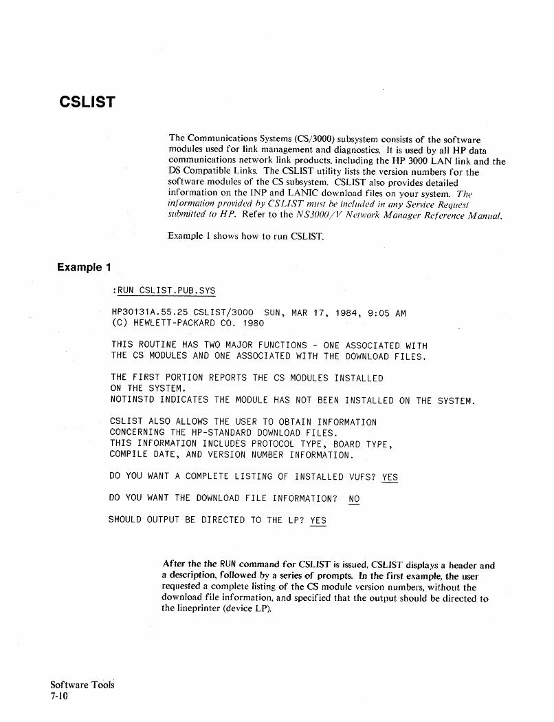
CSLIST
The Communications Systems (CS/3000) subsystem consists of the softwaremodules used for link management and diagnostics. It is used by all HP datacommunications network link products, including the HP 3000 LAN link and theDS Compatible Links. The CSLIST utility lists the version numbers for thesoftware modules of the CS subsystem. CSLIST also provides detailedinformation on the INP and LANIC download files on your system. Theinformation provided by CS LIST must be included in any Service Requestsubmitted to liP. Refer to the N S30()OIV Network Manager Reference Manual.
Example 1 shows how to run CSLIST.
Example 1
:RUN CSLIST.PUB.SYS
HP30131A.55.25 CSLIST/3000 SUN, MAR 17, 1984, 9:05 AM(C) HEWLETT-PACKARD co. 1980
THIS ROUTINE HAS TWO MAJOR FUNCTIONS - ONE ASSOCIATED WITHTHE CS MODULES AND ONE ASSOCIATED WITH THE DOWNLOAD FILES.
THE FIRST PORTION REPORTS THE CSMODULES INSTALLEDON THE SYSTEM.NOTINSTDINDICATES THE MODULE HAS NOT BEEN INSTALLED ON THE SYSTEM.
CSLIST ALSO ALLOWS THE USER TO OBTAIN INFORMATIONCONCERNING THE HP-STANDARD DOWNLOAD FILES.THIS INFORMATION INCLUDES PROTOCOL TYPE,BOARD TYPE,COMPILE DATE, AND VERSION NUMBER INFORMATION.
DO YOU WANT A COMPLETE LISTING OF INSTALLED VUFS? YES
DO YOU WANT THE DOWNLOAD FILE INFORMATION? NO
SHOULD OUTPUT BE DIRECTED TO THE LP? YES
After the the RUN command for CSLJST is issued, CSLJST displays a header anda description, followed by a series of prompts. In the first example, the userrequested a complete listing of the CS module version numbers,without thedownload file information, and specified that the output should be directed tothe lineprinter (device LP).
Software Tools7-10

Example 2
Example 2 shows a typical listing of CS modules produced by CSLIST.
HP30131v.uu.ff CSLIST/3000 SUN, MAR 17, 1985, 9:05 AM(C) HEWLETT-PACKARD co. 1980
COMPLETE LISTING OF INSTALLED VUFS NOW BEING PRODUCED.OUTPUT GOING TO DEVICE LP.
COMSYS1 INSTALLED VUF IS v.uu.ffCOMSYS2 INSTALLED VUF IS v.uu.ffCOMSYS3 INSTALLED VUF IS v.uu.ffCOMSYS4 INSTALLED VUF IS v.uu.ffCOMSYS5 INSTALLED VUF IS v.uu.ffCSUTILITY INSTALLED VUF IS v.uu.ffCSDUMMY INSTALLED VUF IS v.uu.ffCSDUMP INSTALLED VUF IS v.uu.ffTRACPROG INSTALLED VUF IS v.uu.ffIOINPO INSTALLED VUF IS v.uu.ffDSM INSTALLED VUF IS v.uu.ffINPDPAN INSTALLED VUF IS v.uu.ffNETCONF INSTALLED VUF IS v.uu.ffCSLIST INSTALLED VUF IS v.uu.ffIOLAND INSTALLED VUF IS v.uu.ffLANDPAN INSTALLED VUF IS v.uu.ffLANDIAG INSTALLED VUF IS v.uu.ff
In the first example, the download file information was not selected. SinceCSLIST lists information on all of the download files for all of the HP 3000products installed on your system, requesting the download file information mayproduce a lengthy listing.
The alternative, recommended if you want to check a specific download file, isto use CSLIST with an entrypoint. The entrypoint, either LAN or IN P, isappended to the run command, as shown in Example 3 below. When you useCSLIST with an entrypoint, CSLIST displays an abbreviated description andprompts for the download file for which you need information.
Software Tools7-11
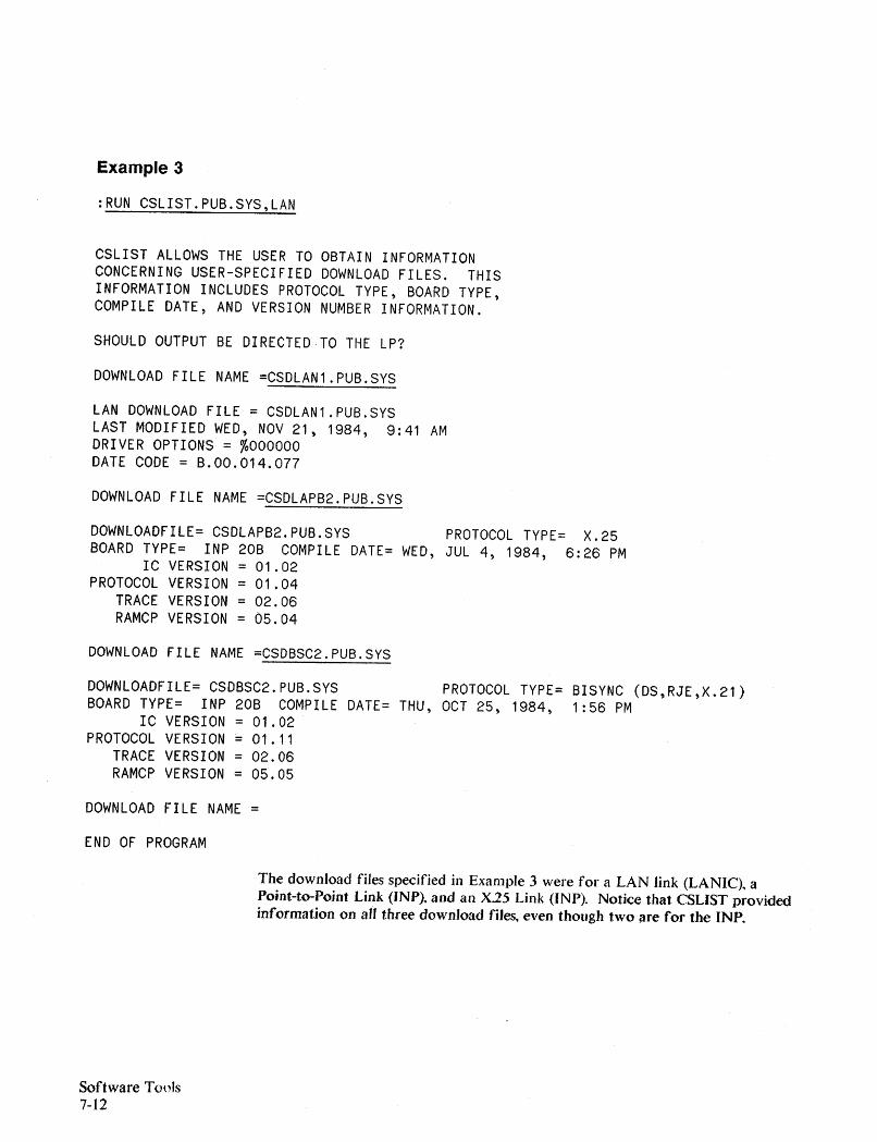
Example 3
:RUN CSLIST.PUB.SYS,LAN
CSLIST ALLOWS THE USER TO OBTAIN INFORMATIONCONCERNING USER-SPECIFIED DOWNLOAD FILES. THISINFORMATION INCLUDES PROTOCOL TYPE, BOARD TYPE,COMPILE DATE, AND VERSION NUMBER INFORMATION.
SHOULD OUTPUT BE DIRECTED·TO THE LP?
DOWNLOAD FILE NAME =CSDLAN1.PUB.SYS
LAN DOWNLOAD FILE = CSDLAN1.PUB.SYSLAST MODIFIED WED, NOV 21, 1984, 9:41 AMDRIVER OPTIONS = %000000DATE CODE = B.00.014.077
DOWNLOAD FILE NAME =CSDLAPB2.PUB.SYS
DOWNLOADFILE= CSDLAPB2.PUB.SYSBOARD TYPE= INP 20B COMPILE DATE= WED,
IC VERSION = 01.02PROTOCOL VERSION = 01.04
TRACE VERSION = 02.06RAMCP VERSION = 05.04
DOWNLOAD FILE NAME =CSDBSC2.PUB.SYS
PROTOCOL TYPE= X.25JUL 4, 1984, 6:26 PM
DOWNLOADFILE= CSDBSC2.PUB.SYS PROTOCOL TYPE= BISYNC (DS,RJE,X.21)BOARD TYPE= INP 20B COMPILE DATE= THU, OCT 25, 1984, 1:56 PM
IC VERSION = 01.02PROTOCOL VERSION = 01.11
TRACE VERSION = 02.06RAMCP VERSION = 05.05
DOWNLOAD FILE NAME =
END OF PROGRAM
The download files specified in Example 3 were for a LAN link (LANIC), aPoint-to-Point Link (JNP). and an X25 Link (INP). Notice that CSLIST providedinformation on all three download files, even though two are fOT the INP.
Software Tools7-12
DSLIST
For the modules of the OS Services subsystem of NS3000jV, and for any of theOS Compatible Links installed on your system, use the OSLIST program installedin the PUB group of the SYS account to obtain a list of the versions of thesoftware modules.
In the OSLIST display, shown in the example below, notice that most of themodules are grouped under a product number heading. There is also a commonmodule heading for the utilities, including this one, that apply to all the DScompatible links.
All modules shown, except those for OSNjX.25, should be displayed on yoursystem. The DSNjOS HP32189B modules are used by the Point-to~PointLinksand by the DS Services subsystem of NS3000jV. The DSNjX.25 HP32191Bmodules are installed with the X.25 Network Link; they only appear if an X.25Link is installed on your system. The CS HP30131A modules show a subset ofthe display provided by CSLIST. The COMSYS module is an overall versionnumber for the CS modules. The NETCONF module is the utility used for thenetwork configuration of the X.25 Network Link, described in the DSN/ X.25for the H P 3000 Reference Manual.
It is essential that:
- all the OS software modules installed on the system have the same versionidentification;
- all the X.25 software modules (if installed) have the same version; and,
- all the common and CS modules have the same version
in order to ensure successful operation. The information provided by DSLISTshould be included in any SR submitted. Refer to the NS3000/V NetworkManager Reference Manual.
Software Tools7-13

Example
Software Tools7-14
:RUN DSLIST.PUB.SYS
HEWLETT PACKARD 32189v.uu.ff DSLISTj3000 SUN, MAR 17, 1985, 7:07 PM
DSNjDS HP32189B:MODULE VERSION
SL DSSEGS v.uu.ff, INTERNAL FIX xxxSL DSRTECALL v.uu.ff, INTERNAL FIX xxx
DSMON v.uu.ff, INTERNAL FIX xxxDSTEST v.uu.ff, INTERNAL FIX xxxDS2026 v.uu.ff, INTERNAL FIX xxxDS2026CN' v.uu.ff, INTERNAL FIX xxxDSCOPY v.uu.ff, INTERNAL FIX xxxIODSO v.uu.ff, INTERNAL FIX xxxIODSTRMO v.uu.ff, INTERNAL FIX xxxIODSTRMX v.uu.ff, INTERNAL FIX xxx
DSNjX.25 HP32191B:MODULE VERSIONDSMONX v.uu.ff, INTERNAL FIX xxxIODSX v.uu.ff, INTERNAL FIX xxxIOPADO v.uu.ff, INTERNAL FIX xxxIOPAD1 v.uu.ff, INTERNAL FIX xxx
COMMON MODULES:MODULE VERSION
SL DSIOM v.uu.ff, INTERNAL FIX xxxDSDUMP v.uu.ff, INTERNAL FIX xxxDSLIST v.uu.ff, INTERNAL FIX xxx
CS SUBSYSTEM HP30131A:MODULE VERSION
SL COMSYS v.uu.ff, INTERNAL FIX xxxNETCONF v.uu.ff, INTERNAL FIX xxx
END OF PROGRAM
In the example, both Point-to-Point and X.25 Network Links were installed onthe system. If X.25 was not installed, the DSLIST program would display amessage IINOT INSTALLED II under the DSN/X.25 HP32191B heading, and the CSmodule NETCONF would not be displayed.
Troubleshooting Flowcharts
Introduction
A
This appendix suggests some procedures, in flowchart format, for use introubleshooting your IEEE 802.3 LAN link. These procedures can help you finda faulty field replaceable unit (FRU).
A LAN comprised of HP 3000 MPE-V based nodes is presumed. For a moregeneral IEEE 802.3 LAN troubleshooting approach, refer to the LAN LinkHardware Trolfbleshooting M anlfal (Coaxial Cable LANs), 5955-7681 (HP CEHandbook version 5959-2217), or the H P StarLAN Diagnostics andTroubleshooting M anlfal lor PCs, 50906-90060.
Figure A-I is an overview of the procedures, followed by the following:
• the troubleshooting flowcharts,
• supplemental Remote Note Testing information, and
• Use of "Software Line Tests".
The troubleshooting procedures can be modified as the conditions require.Experienced users may wish to alter the sequence (or actual implementation) ofeach procedure, especially for obvious faults. However, because each path in theprocedures depends on previous outcomes, deviating from the procedures maycause troubleshooting errors that can be misleading.
NOTE
Recall that the LAN Node Diagnostic (LANDIAG) Test 16, Hood LoopbackTest, does not apply to HP StarLAN connections. For StarLAN connections,refer to LANDIAG Test 14 (see Chapter 4).
Troubleshooting FlowchartsA-I
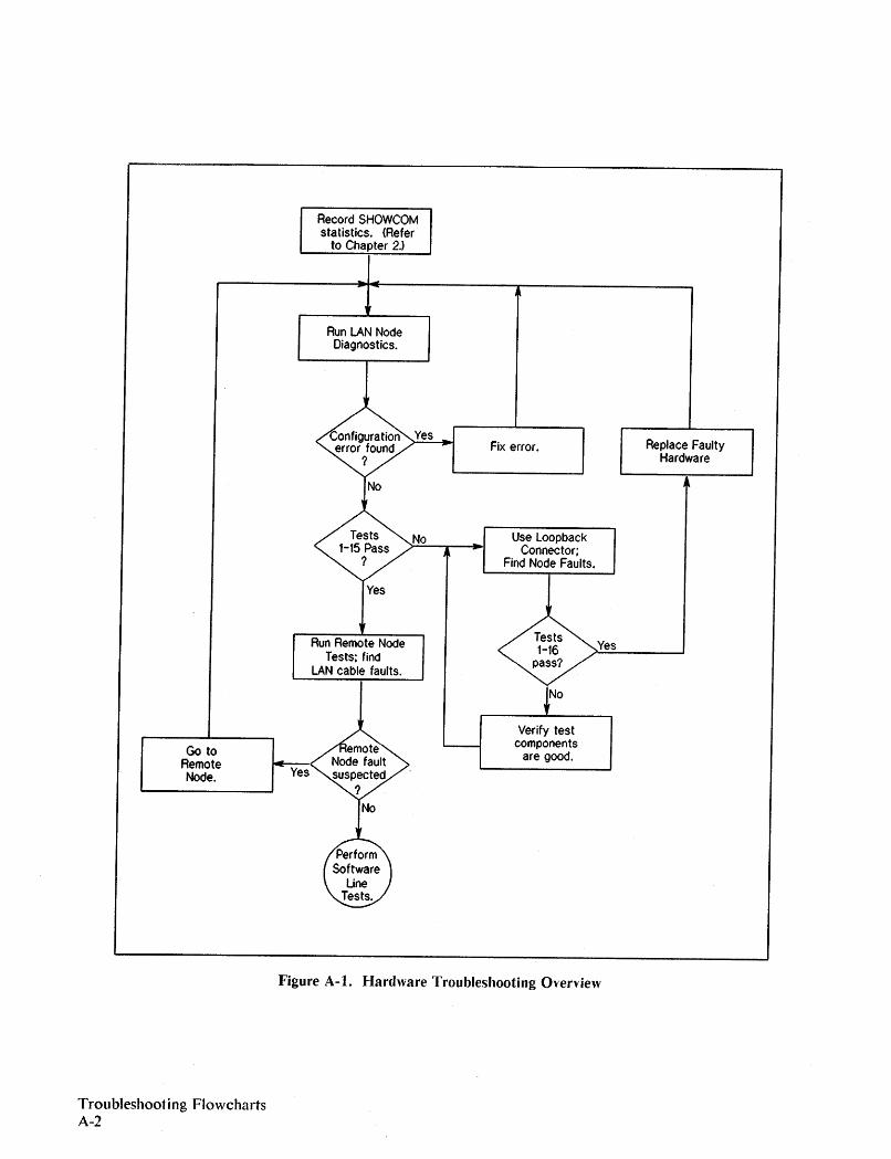
Record SHOWCOMstatistics. {Refer
to Chapter 2'>
Run LAN NodeDiagnostics.
Yes
Yes
Run Remote NodeTests; find
LAN cable faults.
No
Fix error.
Use loopbackConnector;
Find Node Faults.
~NO
Yes
Replace FaultyHardware
Go toRemoteNode. Yes
Verify testcomponents
are good.
Troubleshooting FlowchartsA-2
Figure A-t. Hardware Troubleshooting O"erview
LAN Node Diagnostic Flowcharts
The troubleshooting flowcharts are presented on the following pages. Start withFlowchart 1.
Troubleshooting FlowchartsA-3
Flowchart 1
The first task involves determining if the configuration table and hardwarematch. For example, there is a possibility that the I/O configuration table for theLANIC card may have been entered wrong or the wrong LDEV was specified.
Refer to Chapter 4 for details on running the LAN Node diagnostic.
On successful completion of this flowchart, you should be confident that thehost has confirmed a responding channel exists at the specified LDEV, and thatit is a LANIC card. Refer to the NS3000/V Network Manager Re/erenceManual for information about verification of Network (NMMGR)configuration.
Troubleshooting FlowchartsA-4
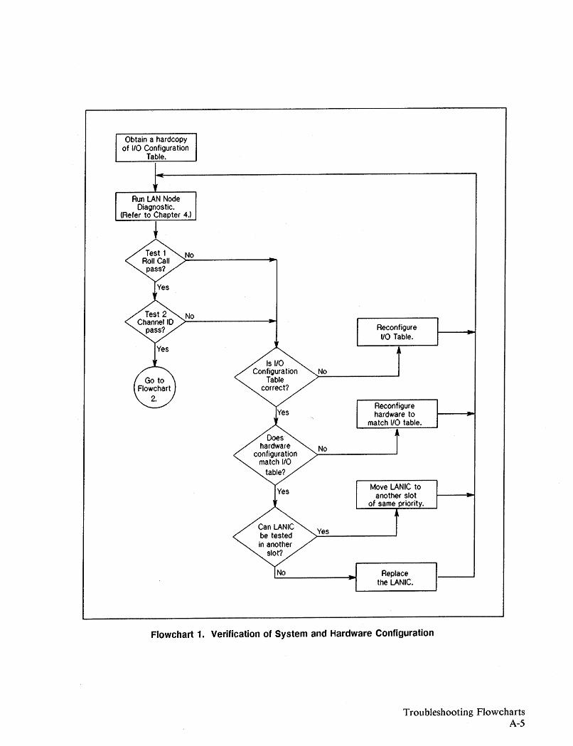
Obtain a hardcopyof 110 Configuration
Table.
Run LAN NodeDiagnostic.
(Refer to Chapter 4.)
• No
No
Reconfigure110 Table.
No
Reconfigurehardware to
match 110 table.
No
Move LANIC toanother slot
of same priority.
Replacethe LANIC.
Flowchart 1. Verification of System and Hardware Configuration
Troubleshooting FlowchartsA-5
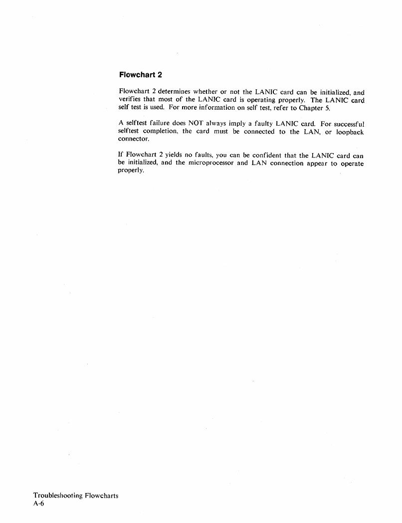
Flowchart 2
Flowchart 2 det.ermines whet.her or not the LANIC card can be initialized, andverifies that most of the LANIC card is operating properly. The LANIC cardself test is used. For more information on self test, refer to Chapter 5.
A selftest failure does NOT always imply a faulty LANIC card. For successfulselftest completion, the card must be connected to the LAN, or loopbackconnector.
If Flowchart 2 yields no faults, you can be confident that the LANIC card canbe initialized, and the microprocessor and LAN connection appear to operateproperly.
Troubleshooting FlowchartsA-6
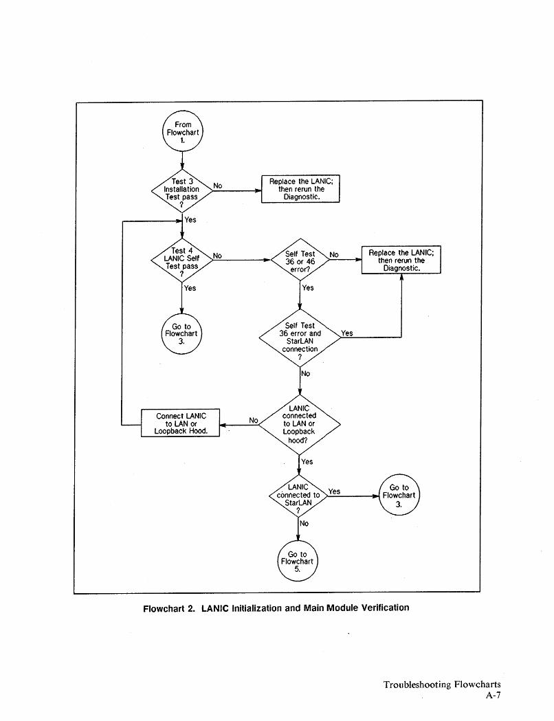
Connect LANICto LAN or
Loopback Hood.
No
No
No
Replace the LANIC;then rerun the
Diagnostic.
Yes
Replace. the LANIC;then rerun the
Diagnostic.
Flowchart 2. LANIC Initialization and Main Module Verification
Troubleshooting FlowchartsA-7
Flowchart 3
Flowchart 3 verifies operation of the LANIC card to 51MB/1MB interface. Asubtle dependency exists between system operation and test execution. Refer todetailed descriptions of LANDIAG Tests 9 and 10 if these tests fail (see Chapter4).
If Flowchart 3 successfully passes, the following are true:
- the HP 3000 can communicate with the LANIC,
- the LANIC card responds as expected, and
- the LANIC can correctly access system memory for DMA processes.
TrOllbleshooting FlowchartsA-8
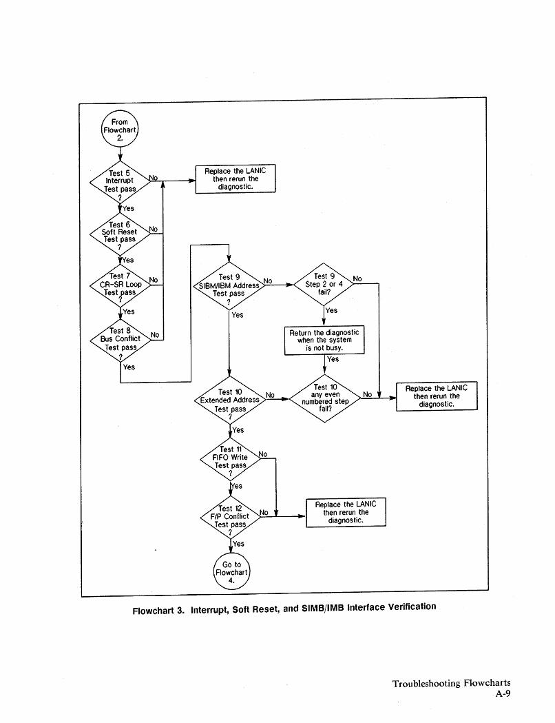
Return the diagnosticwhen the system
is not busy.
Replace the LANICthen rerun the
diagnostic.
Replace the LANICthen rerun the
diagnostic.No
No
Yes
Replace the LANICthen rerun the
diagnostic.
Flowchart 3. Interrupt, Soft Reset, and SIMB/IMB Interface Verification
TrOllbleshooting FlowchartsA-9
Flowchart 4
In Flowchart 4, LANDIAG evaluates that portion of the node directly related tocommunications on the LAN. Specifically, the LAN coprocessor, card·to~LAN
interface, and LAN attachment hardware are exercised.
Other LAN features tested during self test include:
1. multicast addressing. 2. CRC generation/detection
3. MAU/ThinMAU jabber protection (coaxial cable connections only)4. SQE disable operation (coaxial cable connections only)5. heartbeat detection (coaxial cable connections only)
If Flowcharts I through 4 pass with no faults indicated, the node hardware ispresumed good.
However, marginal hardware faults may stiJJ exist, especially for coaxial LANconnections. These include MAU/ThinMAU faults that are difficult to detectby simply by bouncing test frames off the LAN cable.
Marginal faults generally result in network performance degradation. Forexample, .slight collision detect circuitry faults may cause frame check sequence(FeS) errors, Or, a weak MAU/ThinMAU transmitter or receiver may result inframes not being received by the intended node.
The remaining flowcharts (Flowcharts 5 through 9) are intended to help findmarginal faults on coaxial cable LAN connections.
Troubleshooting FlowchartsA-tO

Yes
>N._o__-i.....,IRePI.ce the LANIC.
Use Test 14 andLoopback connectorto find Node Fault.
No LANIC is outdated.Replace with
current version.
PerformRemote Node Tests.
Flowchart 4. LAN Coprocessor, Loopback and Date,. Code Verification
Troubleshooting FlowchartsA-ll
Flowchart 5
NOTE
Flowcharts 5 through 9 employ LANDIAG Test #16 and apply to coaxial cableLAN connections only.
Flowchart 5 implements LANDIAG Test #16 to directly or indirectly check thefollowing hardware:
1. LANIC card,2. LANIC card cable (internal AUI for Series 39/4X/5X/6X/70 systems),3. AUI cabling,4. MAU/ThinMAU,5. Coaxial cable and associated hardware (Tap/BNC Tee connectors, barrels,
connectors, terminators, etc.).
For running Test 16, use of a known good loopback hood and MAU/ThinMAUis required. A loopback hood and MAU/ThinMAU can be verified as knowngood by testing them on a good node. Refer to Chapter 4 for the use of Test 16.
Flowchart 5 checks for liMAU power-on" errors arising from Test 16, and directsthe user to the next flowchart, as appropriate.
Troubleshootiog FJowchartsA-12
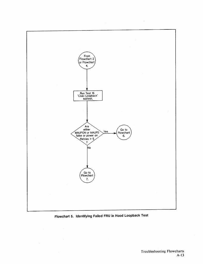
Run Test 16'Coax Loopback'
subtest.
No
Flowchart 5. Identifying Failed FRU in Hood Loopback Test
Troubleshooting FlowchartsA-i3
Flowchart 6
If MAU/ThinMAU power-on errors occur, or power-on attempts are excessive(more than 5), the following hardware may be faulty:
1. LANIC card2. Internal cable short circuits (Series 39/4X/5X/6X/70 systems only),3. AUI cable short circuits,4. MAU/ThinMAU.
Flowchart 5 provides steps to identify faulty hardware.
Troubleshooting FlowchartsA-14

Run Test 16 '25 ohm' subtestwith a MAU Loopback hood
and good internal AUIconnected to LANIC.
YesReplace the LANIC;
then rerun theDiagnostic.
Run Test 16 '25 ohm' subtestwith a MAU Loopback hood
at the end of a sectionof AUI.
Replace original MAUand rerun Diagnostic.
Replace last sectionof AUf tested; then
run Diagnostic.
Proceed to nextsection of AUI.
Flowchart 6. Identifying MAUjThinMAU Power-On Faults
Troubleshooting FlowchartsA-i5
Flowchart 7
Flowchart 7 checks the ability of the LANIC card to transmit and receivepackets on the LAN cable bY_tusing a known good loopback hood andMAU/ThinMAU.
Note that both "25 ohm" and "50 ohm" subtests are performed. The "50 ohm"subtest verifies collision detection operation. This is important because theinability of a node to detect collisions can cause serious degradation of networkperformance.
Troubleshooting FlowchartsA..16
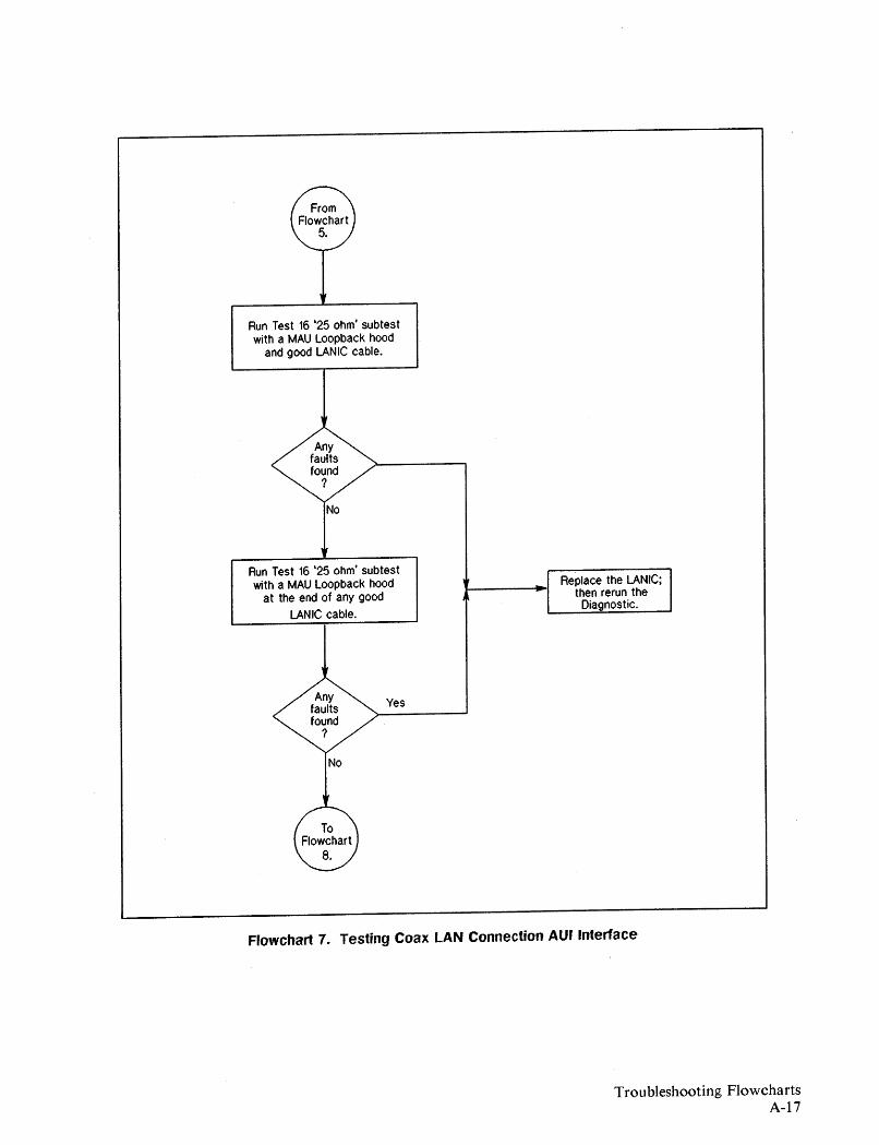
Run Test 16 '25 ohm' subtestwith a MAU Loopback hood
and good LANIC cable.
Run Test 16 '25 ohm' subtestwith a MAU Loopback hood
at the end of any good
LANIC cable.
Replace the LANIC;then rerun theDiagnostic.
Yes
Flowchart 7. Testing Coax LAN Connection AU' Interface
TrOllbleshooting FlowchartsA-17
Flowchart 8
Flowchart 8 systematically checks each AUI cable connecting the LANIC cardto the LAN. Only the '25 ohm' test is used.
Troubleshooting FlowchartsA-IS
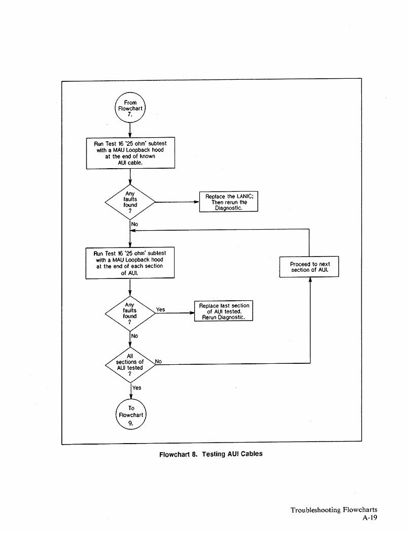
Run Test 16 '25 ohm' subtestwith a MAU Loopback hood
at the end of knownAUI cable.
Run Test 16 '25 ohm' subtestwith a MAU Loopback hoodat the end of each section
of AUI.
Replace the LANIC;Then rerun the
Diagnostic.
Proceed to nextsection of AUI.
Yes
No
Replace last sectionof AUI tested.
Rerun Diagnostic.
Flowchart 8. Testing AUI Cables
Troubleshooting FlowchartsA-19

Flowchart 9
Using Test 16, Flowchart 9 checks the operation of the coaxial cable. Here. theloopback hood is removed, and the known good MAU/ThinMAU is attached tothe coaxial cable in place of the originally installed MAU/ThinMAU.
If the test now runs successfully, the originaJly instaJled MA U/ThinMAU isfaulty.
If the test still fails, the coaxial cable contains a fault. An open Tap, that is, onethat does not make contact with the coaxial cable conductors, can be verified byrepeating the test on a nearby Tap. A shorted Tap is not easily verified, since theentire cable will appear faulty.
If the coaxial cable appears to be faulty, perform LANDIAG Test #17, RemoteNode Tests, or refer to the LAN L;nk Hardware Trollbleshoor;ng Manual,5955-7681 (HP CE Handbook version 5959-2217).
Troubleshooting FlowchartsA-20
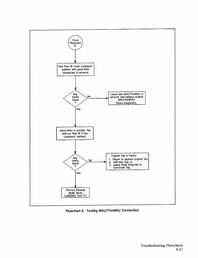
Run Test 16 'Coax loopback'subtest with good MAUconnected to network.
leave new MAU/ThinMAU or;>-N_O ....., network and replace original
MAUlThinMAU.Rerun Dia nostic.
Yes
Move MAU to another Tapand run Test 16 'Coax
loopback' subtest.
No
Original Tap is Faulty:1. Repair or replace original Tap.2. Add new Tap, or3. leave Node attached to
functional Tap.
Perform RemoteNode Tests.
(LANDIAG Test 17.)
Flowchart 9. Testing MAUjThinMAU Connection
Troubleshooting FlowchartsA-21
Using Test 17 - The Remote Node Test (RNT)
LANDIAG Test 17, the Remote Node Test, aJlows the user to send frames to andreceive frames from remote nodes on the network. It can be llsed to isolatefaults on the LAN between operational nodes. (Refer to Chapter 4, LAN NodeDiagnostic, for details on performing LANDIAG Test 17.)
Coaxial Cable LAN. For coax LANs, a binary search is used in conjunction withTest 17. In a binary search, the coax cable is first divided into two smaller LANs,which are each tested using Test 17. Each smaller LAN that fails is furtherdivided, and the process continues until the LAN cable sections can no longer beconveniently divided. At that point, either the fault is found and corrected, orthe faulty cable section is replaced.
For other alternatives, refer to the LA N L;nk Hardware Troub/eshooll'ng M anua/,5955-7681 (HP CE Handbook version 5959-2217).
HP StarLAN. For a StarLAN with multiple Hubs, the Hubs are systematicallyisolated from one another while Test 17 is run between connected nodes. In thisway, faults associated with a Hub or remote node can be quickly found.
For more information, refer to the H P Stm'LA N Dhlgnosth's andTrolfb/eshoot;ngManual lor pes, 50906-90060.
Troubleshooting FlowchartsA-22
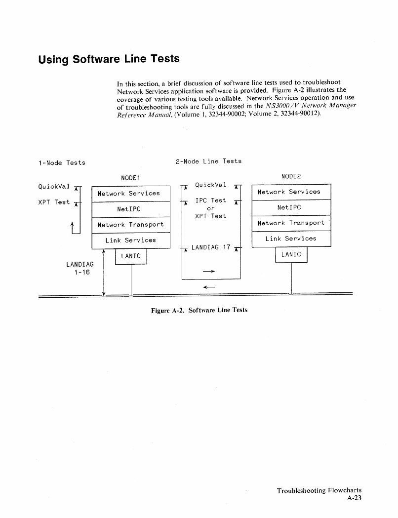
Using Software Line Tests
In this section, a brief discussion of software line tests used to troubleshootNetwork Services application software is provided. Figure A-2 illustrates thecoverage of various testing tools available. Network Services operation and useof troubleshooting tools are fully discussed in the N S3000IV N e/work ManagerReference Manual, (Volume 1,32344-90002; Volume 2, 32344-90012).
1-Node Tests 2-Node Line Tests
NODE1 NODE2QuickVal QuickVal
Network Services Network ServicesXPT Test IPC Test
NetIPC or NetIPCXPT Test
Network Transport Network Transport
Link Services Link ServicesLANDIAG 17
LANDIAG1-16 ~
===~:='.l..====+-====l..===
Figure A-2. Software Line Tests
TrOllbleshooting FlowchartsA-23
NOTE
Before running the software line tests, use the LAN Node Diagnostic(LANDIAG) to ensure that there are no hardware problems.
Also, the software should be reset -- shut down and restart the NetworkTransport and Network Services. Issue the command
SHOWCOM ldev; RESET
to set the values of the SHO\VCOM status display to zero.
Be sure to refer to the NS3000/V Network Manager Re/erence Manual beforeattempting to perform software line tests.
The HP 3000 LAN link includes three software line tests that can be used toverify the operation of the NS3000/V and LAN link software. The line tests areXPT, IPC and QuickVal. They can be run on a single node (software loopback),and between nodes.
The XPT and IPC line tests are both interactive and use the NetlPC intrinsics.They verify operation of the Network Transport Level.
QuickVal, which runs in batch mode, checks the netvi-'ork services.
Troubleshooting FlowchartsA-24
Procedures
Single Node Testing. On a single node, XPT verifies operation of the local
Network Transport. If it is not functioning properly, the LAN problem has
probably been found and further line testing may not be necessary.
If the local Transport is operating properly, run QuickVal to verify operation of
the services on the node.
Finally, perform a two-node XPT line test.
Two-Node Testing. The two-node XPT line test checks the remote Transport
level, and the local and remote links. If this test reveals an error, refer to the
NS3000/V Network Manager Reference Manual to interpret the results.
Perform any hardware troubleshooting required.
If both the single-node software loopback and two-node XPT line tests reveal no
errors, run the IPe line test between nodes. (Running this test on a single node,
i.e., software loopback, is not necessary since you already checked the transport.)
The two-node IPe line test, in addition to checking the Network Transport and
both links, uses Network Services, specifically Remote Process Management
(RPM). This means that if this test fails, the problem probably lies within the
RPM capabilities of the Network Services.
If the IPe two-node test reveals no errors, you should nm QuickVal between
nodes to check all Network Services other than RPM. QuickVal tests the services
by executing the intrinsics and commands of each service.
If more than one service is not working, it could mean that DSDAD and its
associated modules are not functioning properly. DSDAD is the control process
for all Network Services.
Troubleshooting FlowchartsA-25

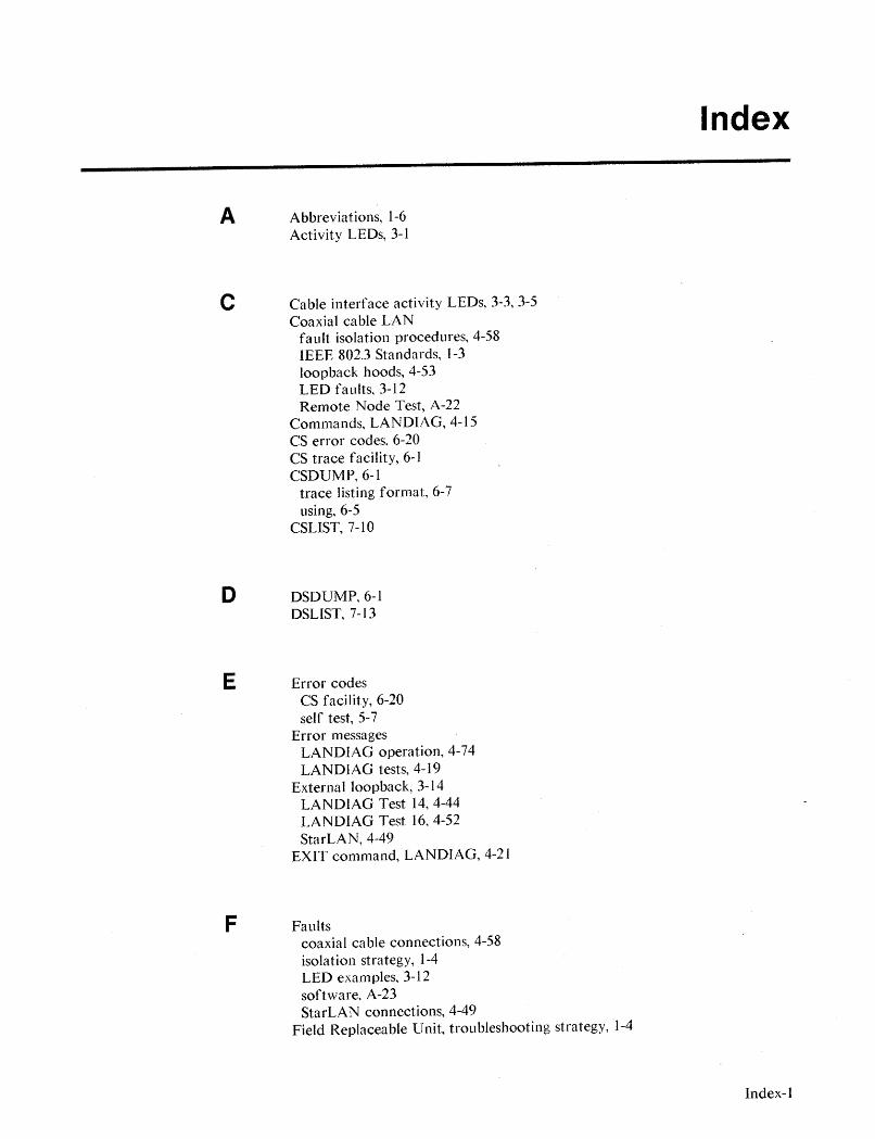
A Abbreviations, 1-6Activity LEDs, 3-1
C Cable interface activity LEDs, 3-3,3-5Coaxial cable LAN
fault isolation procedures, 4-58IEEE 802.3 Standards, ]-3loopback hoods, 4-53LED faults, 3-12Remote Node Test, A-22
Commands, LANDIAG, 4-15CS error codes, 6-20CS trace facility, 6-1CSDUMP,6-1
trace listing format, 6-7using, 6-5
CSLIST, 7-10
D DSDUMP,6-1DSLIST,7-13
E Error codesCS facility, 6-20self test, 5-7
Error messagesLANDIAG operation, 4-74LANDIAG tests, 4-19
External loopback, 3- J4LANDIAG Test 14, 4-44LANDIAG Test 16, 4-52StarLAN, 4-49
EXIT command, LANDIAG, 4-2 J
F Faultscoaxial cable connections, 4-58isolation strategy, 1-4LED examples, 3-12software, A-23StarLAN connections, 4-49
Field Replaceable Unit, troubleshooting strategy, 1-4
Index
Index-l
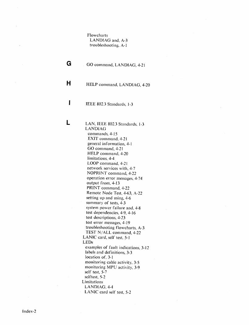
Index-2
FlowchartsLANDIAG and, A-3troubleshooting, A-I
G GO command, LANDIAG, 4-21
H HELP command, LANDIAG, 4-20
IEEE 802.3 Standards, 1-3
L LAN, IEEE 802.3 Standards, 1-3LANDIAG
commands, 4-15EXIT command, 4-21general information, 4-1GO command, 4-21HELP command, 4-20limitations, 4-4LOOP command, 4-21network services with, 4-7NOPRINT command, 4-22operation error messages, 4-74output from, 4-13PRINT command, 4-22Remote Node Test, 4-63, A-22setting up and using, 4-6summary of tests, 4-3system power failure and, 4-8test dependencies, 4-9, 4-16test descriptions, 4-23test error messages, 4-19troubleshooting flowcharts, A-3TEST N/ALL command, 4-22
LANIC card, self test, 5-1LEDs
examples of fault indications, 3-12labels and definitions, 3-3location of, 3-1monitoring cable activity, 3-5monitoringMPU activity, 3-9self test, 5-7selftest, 5-2
LimitationsLANDIAG,4-4LANIC card self test, 5-2

Link-level address, 4-14LISTLOG5, 7-2Loopback hood
coaxial cable LANs, 4-53LANDIAG Test 14 and, 4-44LANDIAG Test 16 and, 4-52LANIC self test and, 4-28StarLAN, 4-49
LOOP command, LANDIAG, 4-21
M Memory dump, 7-1MPU activity LEDs, 3-3, 3-9
N Network map, 1-5Network services, LANDIAG with, 4-7NMMAINT, 7-5Nomenclature, 1-6NOPRINT command, LANDIAG, 4-22NSDPAN5/NSDUMPJ, 7-1
P Power failure, LANDIAG and, 4-8Procedures
LANDIAG and, A-3troubleshooting, A-I
PRINT command, LANDIAG, 4-22
R Remote Node Test, A-22LANDIAG, 4-63
Repair, strategy, 1-4
S Self testcodes, 5-7from LANDIAG, 4-27general information, 5-1limitations, 5-2loopback hood and, 4-28LEDs, 5-2
SHOWCOM, 2-1LANDIAG with, 4-70
Software fault tests, A-23StarLAN
fault isolation procedures, 4-49IEEE 802.3 Standard, 1-3
Index-3
Index-4
100pback hood, 4-49LED faults, 3-15Remote Node Test, A-22
Station address, 4-14
T Terminology, abbreviations and nomenclature, 1-6Tests, software faults, A-23Tests, LANOIAG
dependencies, 4-9, 4-16description, 4-23summary, 4-3
TEST N/ALL command, LANOIAG, 4-22Tools
CS trace facility, 6- ICSLIST utility, 7-10OSLIST utility, 7-13LANOIAG,4-1LANIC self test, 5-1LEOs, 3-1LISTLOG5 utility, 7-2memory dump, 7-1NMMAINT utility, 7-5NSOPAN5/NSOUMPJ, 7-1software line tests, A-23SHOWCOM, 2-1troubleshooting, J-2
Tracingactivating, 6-2deactivating, 6-4general information, 6-1
TroubleshootingCS trace facility, 6-1CSLIST utility, 7-10OSLIST utility, 7-13flowchart procedures, A-Igeneral, I-ILANOIAG, 4-1LANIC self test, 5-1LEOs, 3-1LISTLOG5 utility, 7-2memory dump, 7-1NMMAINT utility, 7-5software faults, A-23
. strategy, 1-4SHOWCOM, 2-1tools summa'ry, 1-2

SALES &SUPPORT OFFICESArranged alphabetically by country
Product Line Sales/Support Key Canberra, Australia BELGIUMKey Product Line Capital Territory Hewlett-Packard Belgium SAIN.v.A Analytical Office Blvd de la Woluwe, 100CM Components Hewlett-Packard Australia LId. WoluwedalC Computer Systems 121 Wollongong Street B-1200 BRUSSELSE Electronic Instruments' Measurement Systems FYSHWICK, A.C.T. 2609 Tel: (02) 762-32-~M Medical Products Tel: 80 4244 Telex: 23-494 paloben bruP Personal Computation Products Telex: 62650 A,C,CM,E,M,P. Sales only for specific product line Gable: HEWPARD Canberra•• Support only for specific product line C,CM,E,P BERMUDAIMPORTANT:These symbols designate general product line Melbourne, Victoria
Applied Computer Technologies
capability.They do not insure sales or support availability for all Atlantic House Building
products within aline, at all locations.Contact your local sales Office Par-La-Ville Road
office for information regarding locations where HP support is Hewlett-Packard Australia LId. Hamilton 5
available for specific products. 31-41 Joseph Street Tel: 295-1616BUCKBURN, Victoria 3130 PTel: 895·2895
HEADQUARTERS OFFICES Telex: 31·024 BRAZILIf there is no sales office listed for your area, contact one of these Cable: HEWPARD Melbourne Hewlett-Packard do Brasilheadquarters offices. A,C,CM,E,M,P l.e.C. L1da.
NORTH/CENTRAL AFRICA MEDITERRANEAN AND ANGOLA Perth, Western AustraliaAlameda Rio Negro, 750Alphaville
Hewlett-Packard SA MIDDLE EAST Telectra Angola LDA Office 06400 BARUERI SP7, rue du Bois-du-Lan Hewlett-Packard SA Empresa T~cnica de Equipamentos Hewlett-Packard Australia LId. Tel: (011) 421.1311CH-1217 MEYRIN 1, Switzerland Mediterranean and Middle East Rua Conselheiro Julio de Vilhema, 16 261 Stirling Highway Telex: (011) 33872 HPBR-BRTel: (022) 83 12 12 Operations Caixa Postal 6487 CLAREMONT, WA 6010 Cable: HEWPACK Sao PauloTelex: 27835 hmea Atrina Centre LUANDA Tel: 383-2188 A,C,CM,E,M,PCable: HEWPACKSA Geneve 32 Kifissias Ave. Tel: 35515,35516
Telex: 93859
Paradissos-Amarousion, ATHENS Cable: HEWPARD Perth Hewlett-Packard do Brasil
ASIA GreeceTelex: 3134 A,C,CM,E,M,P l.e.C. L1da.
Hewlett-Packard Asia LId. Tel: 68288 11E,C· Praia de Botafago 228
47IF, 26 Harbour Rd., Telex: 21-6588 HPAT GR ARGENTINASydney, New South 6° Andar-conj 614
Wanchai, HONG KONG Cable: HEWPACKSA Athens Wales Office Edificio Argentina - Ala A
G.P.O. Box 863, Hong Kong Hewlett-Packard Argentina SA Hewlett-Packard Australia LId. 22250 RIO DE JANEIRO
Tel: 5-8330833 UNITED KINGDOM Montaneses 2140I 50 17·23 Talavera Road Tel: (021) 552-6422
Telex: 76793 HPA HX Hewlett-Packard LId. 1428 BUENOS AIRES P.O. Box 308 Telex: 21905 HPBR-BR
Cable: HPASIAL TO Nine Mile Ride Tel: 783-4886/4836/4730 NORTH RYDE, N.S.W. 2113 Cable: HEWPACK Rio de Janeiro
Easthampstead, WOKINGHAM Cable: HEWPACKARG Tel: 888-4444 A,C,CM,E,P·
CANADA Berkshire, IRGII 3LL A,C,CM,E,P Telex: 21561 ConvexIVan DenHewlett-Packard (Canada) LId. Tel: 0344773100 Biotron S.A.C.l.e.1. Cable: HEWPARD Sydney Rua Jose Bonifacio6877 Goreway Drive Telex: 848805 Av. Paso Colon 221, Piso 9 A,C,CM,E,M,P 458 Todos Os SantosMISSISSAUGA, Ontario L4V 1M8 1399 BUENOS AIRES CEP 20771Tel: (416) 678·9430 EASTERN USA CM AUSTRIA RIO DE JANEIRO, RJTelex: 610·492·4246 Hewlett-Packard Co. Hewlett-Packard Ges.m.b.h. Tel: 591-0197
4 Choke Cherry RoadLaboratorio Rodriguez VerkauisbOro Graz Telex: 33487 EGLB BR
EASTERN EUROPE ROCKVILLE, MD 20850 Corswant S.R.L. Grottenhofstrasse 94 AHewlett-Packard Ges.m.b.h. Tel: (301) 258-2000 Misiones, 1156 - 1876 A·8052 GRAZLieblgasse 1 Bernal, Oeste Tel: (0316) 291 5660 ANAMED I.C.E.I. L1da.P.O.Box 72 MIDWESTERN USA BUENOS AIRES Telex: 32375 Rua Bage, 103A-1222 VIENNA, Austria Hewlett-Packard Co. Tel: 252-3958, 252-4991 C,E 04012 SAO PAULO, SPTel: (222) 2500-0 5201 Tollview Drive A Hewlett-Packard Ges.m.b.h.
Tel: (011) 572-6537Telex: 13 4425 HEPA A Telex: 24720 HPBR-BR
ROLLING MEADOWS, IL 60008 Argentina Esanco S.R.L. Lieblgasse 1 M
NORTHERN EUROPETel: (312) 255-9800 Avasco 2328 P.O. Box 72
Hewlett-Packard SA 1416 BUENOS AIRES A·1222 VIENNA Datatronix Electronica L1da.
Uilenstede 475SOUTHERN USA Tel: 541-58-1981, 541-59-2767 Tel: (0222) 2500-0 Av. Pacaembu 746-C11
P.O.Box 999Hewlett-Packard Co.
A Telex: 134425 HEPA A SAO PAULO, SP
NL-1183 AG AMSTELVEEN2000 South Park Place A,C,CM,E,M,P Tel: (118) 260111
The NetherlandsP.O. Box 105005 CM
Tel: 20437771ATLANTA, GA 30348 AUSTRALIA BAHRAIN
Telex: 18919 hpner nlTel: (404) 955-1500 Green Salon CAMEROON
Adelaide, South Austrlill P.O. Box 557 Beriac
SOUTH EAST EUROPE WESTERN USA Office MANAMA B. P. 23
Hewlett-Packard SA Hewlett-Packard Co. Hewlett-Packard Australia Ltd. Tel: 255503-255950 DOUALA
World Trade Center3939 Lankershim Blvd. 153 Greenhill Road Telex: 8441 Tel: 420153
110 Avenue Louis Casal P.O. Box 3919 PARKSIDE, SA 5063 P Telex: 5351
1215 Cointrin, GENEVA, Switzerland LOS ANGELES, CA 91604Tel: 272-5911
C,P
Tel: (022) 98 96 51 Tel: (213) 506-3700 Wael PharmacyTelex: 82536 P.O. Box 648 CANADATelex: 27225 hpser Cable: HEWPARD Adelaide MANAMAA· ,C,CM,E,M,P Tel: 256123 Alberti
Telex: 8550 WAEL BN Hewlett-Packard (Canada) LId.
OTHER INTERNATIONAL Brlsblne, QUMnsllnd E,M 30303rd Avenue N.E.
AREAS Office Zayani Computer SystemsCALGARY, Alberta T2A 6T7
Hewlett-Packard Co. Hewlett-Packard Australia Ltd. 218 Shaik Mubarak BuildingTel: (403) 235-3100
Intercontinental Headquarters 10 Payne Road Government AvenueA,C,CM,E*,M,P*
3495 Deer Creek Road THE GAP, Queensland 4061 P.O. Box 5918 Hewlett-Packard (Canada) LId.PALO ALTO, CA 94304 Tel: 30·4133 MANAMA 11120-178th StreetTel: (415) 857-1501 Telex: 42133 Tel: 276278 EDMONTON, Alberta T5S 1P2Telex: 034-8300 Cable: HEWPARD Brisbane Telex: 9015 Tel: (403) 486-6666Cable: HEWPACK A,C,CM,E,M,P P A,C,CM,E,M,P

o SALES & SUPPORT OFFICES~lJ Arranged alphabetically by country
CANADA (Cont'd) Quebec COLOMBIA ECUADOR FRANCEHewlett-Packard (Canada) Ltd. Instrumentaci6n CYEDE Cia. Ltda. Hewlett-Packard FranceBritish Columbia 17500 Trans Canada Highway H. A. Langebaek & Kier SA Avenida Eloy Alfaro 1749 l.l. Mercure BHewlett-Packard (Canada) Ltd. South Service Road Carrera 4A No. 52A-26 y Belgica Rue Berthelot10691 Shellbridge Way KIRKLAND, Quebec H9J 2X8 Apartado Aereo 6287 Casilla 6423 CCI 13763 Les Milles CedexRICHMOND, Tel: (514) 697-4232 BOGOTA 1, D.E. QUITO AIX·EN·PROVENCEBritish Columbia V6X 2W7 A,C,CM,E,M,P* Tel: 212-1466 Tel: 450-975, 243-052 Tel: (42) 59-41-02Tel: (604) 270-2277 Hewlett-Packard (Canada) Ltd. Telex: 44400 INST CO Telex: 22548 CYEDE ED Telex: 410770FTelex: 610-922-5059 1150 rue Claire Fontaine Cable: AARIS Bogota CM,E,P A,C,E,M,P*A,C,CM,E* ,M,P* QUEBEC CITY, Quebec G1R5G4 CM,E,MMedtronics Hewlett-Packard FranceHewlett-Packard (Canada) Ltd. Tel: (418) 648-0726 Nefromedicas Ltda. Valladolid 524 Madrid 64, rue Marchand Saillant121 - 3350 Douglas Street C Calle 123 No. 9B-31 P.O. 9171, QUITO 61000 ALENCONVICTORIA, British Columbia V8l 3L1 Hewlett-Packard (Canada) Ltd. Apartado Aereo 100-958 Tel: 223-8951 Tel: (33) 29 04 42BOGOTA DE, 10 Telex: 2298 ECKAME EDTel: (604) 381-6616 130 Robin Crescent
Tel: 213-5267, 213-1615 A Hewlett-Packard FranceC SASKATOON, Saskatchewan S7L 6M7Telex: 43415 HEGAS CO 28 rue de la RepubliqueTel: (306) 242-3702A Hospitalar SA
Boite Postale 503Manitoba C Robles 62525026 BESANCON CedexHewlett-Packard (Canada) Ltd. Compumundo Casilla 3590Tel: (81) 83-16-221825 Inkster Blvd. CHILE Avenida 15 # 107-80 QUITOTelex: 361157WINNIPEG, Manitoba R2X 1R3 ASC Ltda. BOGOTAD.E. Tel: 545-250, 545-122C,MTel: (204) 694·2777 Austria 2041 Tel: 214-4458 Telex: 2485 HOSPTL ED
A,C,CM,E,M,P' SANTIAGO Telex: 45466 MARICO Cable: HOSPITALAR-Quito Hewlett-Packard FranceTel: 223-5946,223-6148 P M Chemin des MouillesNew Brunswick Telex: 340192 ASC CKEcuador Overseas Agencies CA Boite PostaIe 162Carvajal, SAHewlett-Packard (Canada) Ltd. C,P
Calle 29 Norte No. 6A-40 Calle 9 de OCtubre #818 69130 ECULlY Cedex (Lyon)814 Main Street Isical Ltda. Apartado Aereo 46 P.O. Box 1296, Guayaquil Tel: (78) 833-81-25MONCTON, New Brunswick E1C 1E6 Av. Italia 634 Santiago CALI QUITO Telex: 310617FTel: (506) 855-2841 Casilla 16475 Tel: 368-1111 Tel: 306022 A,C,E,MC SANTIAGO 9 Telex: 55650 Telex: 3361 PBCGYE EDHewlett-Packard FranceTel: 222-0222 C,E,P MPare d'activitlls du Bois BriardNova Scotia Telex: 440283 JCYCL Cl2, avenue du LacHewlett-Packard (Canada) Ltd. CM,E,M CONGO
EGYPT 91040 EVRY CedexSuite 111Metrolab SA Seric-Congo
Sakrco Enterprises Tel: 6077-9660900 Windmill RoadMonjitas 454 of. 206 B. P. 2105
70, Mossadak Str. Telex: 692315FDARTMOUTH, Nova Scotia B3B 1P7 SANTIAGO BRAZZAVILLEDokki, Giza ETel: (902) 469-7820 Tel: 395752, t398296 Tel: 815034CAIROC,CM,E',M,P* Telex: 340866 METLAB CK Telex: 5262Tel: 706440 Hewlett-Packard France
A Telex: 93146 5, avenue Raymond ChanasOntario COSTA RICAC 38320 EYBENS (Grenoble)Hewlett-Packard (Canada) Ltd. Olympia (Chile) Ltda. Cientifica Costarricense SA Tel: (76) 62-57-983325 N. Service Rd., Unit 3 Av. Rodrigo de Araya 1045 Avenida 2, Calle 5 International Engineering Associates Telex: 980124 HP GRENOB EYBEBURLINGTON, Ontario L7N 3G2 Casilla 256-V San Pedro de Montes de Oca 24 Hussein Hegazi Street CTel: (416) 335-8644 SANTIAGO 21 Apartado 10159 Kasr-el-Ain
C,M' Tel: 225-5044 SAN JOse CAIRO Hewlett-Packard FranceTelex: 340892 OLYMP Tel: 24-38-20, 24-08-19 Tel: 23829, 21641 Rue Fernand. ForestHewlett-Packard (Canada) Ltd. Cable: Olympiachile Santiagochile Telex: 2367 GALGUR CR Telex: 93830 lEA UN l.A. Kergaradec496 Days Road C,P CM,E,M Cable: INTEGASSO 29239 GOUESNOUKINGSTON, Ontario K7M 5R4 E,M* Tel: (98) 41-87-90Tel: (613) 384-2088CHINA, People'. CYPRUS
S.S.C. Medical Hewlett-Packard FranceC Telerexa Ltd.R.publlco' P.O. Box 4809 40 Gezerat EI Arab Street Centre d'aftaires Paris-NordHewlett-Packard (Canada) Ltd. China Hewlett-Packard, Ltd. 14C Stassinos Avenue Mohandessin Batiment Am~re552 Newbold Street 47/F China Resources Bldg. NICOSIA CAIRO Rue de la Commune de ParisLONDON, Ontario N6E 2S5 26 Harbour Road Tel: 62698 Tel: 803844, 805998, 810263 Boite Postale 300Tel: (519) 686-9181 HONG KONG Telex: 2894 LEVIDO CY Telex: 20503 SSC UN 93153 LE BLANC·.SNILA,C,CM,E* ,M,P* Tel: 5-8330833 E,M,P M* Tel: (1) 865-44-52Telex: 76793 HPA HX Telex: 211032FHewlett-Packard (Canada) Ltd.Cable: HP ASIA LTO DENMARK ELSALVADOR C,E,M6877 Goreway DriveA*,M*
Hewlett-Packard A/S IPESA de EI Salvador SAMISSISSAUGA, Ontario L4V 1M829 Avenida Norte 1223 Hewlett-Packard FranceTel: (416) 678-9430 China HeWlett-Packard, Ltd. Datavej 52SAN SAlVADOR Pare d'activitlls CaderaA,C,CM,E,M,P P.O. Box 9610, Beijing DK-3460 B1RKERODTel: 26-6858, 26-6868 Quartier Jean-Mermoz4th Floor, 2nd Watch Factory Main Tel: (02) 81-66-40Telex: 20539 IPESA SAL Avenue du Prllsident JF KennedyHewlett-Packard (Canada) Ltd. Bldg. Telex: 37409 hpas dkA,C,CM,E,P F-33700 MERIGNAC (Bordeaux)2670 Queensview Dr. Shuang Yu Shu, Bei San Huan Rd. A,C,CM,E,M,P
Tel: (56) 34-00-84OTTAWA, Ontario K2B 8K1 Hai Dian District Hewlett-Packard AlS ETHIOPIA Telex: 550105FTel: (613) 820-6483 BEIJINGRolighedsvej 32 Seric-Ethiopia C,E,MA,C,CM,E* ,M,P* Tel: 28-0567 DK-8240 RISSKOV, Aarhus P.O. Box 2764Telex: 22601 CTSHP CN Hewlett-Packard FranceHewlett-Packard (Canada) Ltd.
Cable: 1920 BeijingTel: (06) 17·60-00 ADDIS ABABA Immueble "les 3 B"The Oaks Plaza, Unit #9 Telex: 37409 hpas dk Tel: 185114 Nouveau chemin de la Garde2140 Regent Street A,C,CM,E,M,P C,E Telex: 21150 lAC du Bois BriandSUDBURY, Ontario, P3E 5S8 C,P
44085 NANTES CedexTel: (705) 522-0202 DOMINICAN REPUBLICTel: (40) 50-32-22C Microprog SA FINLAND Telex: 711085F
Hewlett-Packard (Canada) Ltd.Juan Tomas MejIa y Cotes No. 60 Hewlett-Packard Oy C"Arroyo Hondo Piispankalliontie 173790 Victoria Park Ave. SANTO DOMINGO 02200 ESPOO Hewlett-Packard FranceW1UOWDALE, Ontario M2H 3H7 Tel: 565-6268 Tel: 00358-0-88721 125, rue du Faubourg BannierTel: (416) 499-2550 Telex: 4510 ARENTA DR (RCA) Telex: 121563 HEWPA SF 45000 ORLEANSC P A,C,CM,E,M,P Tel: (38) 6801 63

SALES & SUPPORT OFFICESArranged alphabetically by country
Blue Star Ltd.15/16 C Wellesley Rd.PUNE 411011Tel: 22775Cable: BLUE STARA
Blue Star Ltd.2-2-47/1108 Bolarum Rd.SECUNDERABAD 500 003Tel: 72057, 72058Telex: 0155645Cable: BLUEFROSTA,E
Blue Star Ltd.T.C. 7/603 PoornimaMaruthunkuzhiTRIVANDRUM 695 013Tel: 65799, 65820Telex: 0884-259Cable: BLUESTARE
IRAQHewlett-Packard Trading SAService OperationAI Mansoor City 9B/3/7BAGHDADTel: 551-49-73Telex: 212-455 HEPAIRAQ IKC
Computer Maintenance CorporationLtd.115, Sarojini Devi RoadSECUNDERABAD 500 003Tel: 310-184, 345-774Telex: 031-2960C"
INDONESIABERCA Indonesia P.T.P.O. Box 496/Jkt.JI. Abdul Muis 62JAKARTATel: 21-373009Telex: 46748 BERSAL IACable: BERSAL JAKARTAP
BERCA Indonesia P.T.P.O.Box 2497/JktAntara Bldg., 12th FloorJI. Medan Merdeka Selatan 17JAKARTA·PUSATTel: 21-340417, 341445Telex: 46748 BERSAL IAA,C.E,M
BEReA Indonesia P.T.Jalan Kutai 24SURABAYATel: 67118Telex: 31146 BERSAL SBCable: BERSAL·SURABAYAA*,E,M,P
IRELANDHewlett-Packard Ireland Ltd.82/83 Lower Leeson StreetDUBLIN 2Tel: 0001 608800Telex: 30439A.C.CM,E,M.P
Cardiac Services Ltd.Kilmore RoadArtaneDUBLIN 5Tel: (01) 351820Telex: 30439M
INDIAComputer products are sold throughBlue Star Ltd.AII computer repairs andmaintenance service is done throughComputer Maintenance Corp.
Blue Star Ltd.Sabri Complex 2nd Floor24 Residency Rd.BANGALORE 560 025Tel: 55660, 578881Telex: 0845-430Cable: BLUESTARA,C*,CM,E
Blue Star Ltd.Band Box HousePrabhadeviBOMBAY 400025Tel: 4933101, 4933222Telex: 011-71051Cable: BLUESTARA,M
Blue Star Ltd.Sahas414/2 Vir Savarkar MargPrabhadeviBOMBAY 400025Tel: 422-6155, 422-6556Telex: 011-71193 BSSS INCable: FROSTBLUEA.C',CM,E.M
Blue Star Ltd.Kalyan, 19 Vishwas ColonyAlkapuri, BORODA, 390 005Tel: 65235. 65236Cable: BLUE STARA
Blue Star Ltd.7 Hare StreetCALCUTTA 700 001Tel: 230131, 230132Tele~: 021-7655Cable: BLUESTARA,M
Blue Star Ltd.133 Kodambakkam High RoadMADRAS 600 034Tel: 472056. 470238Telex: 041-379Cable: BLUESTARA,M
Blue Star Ltd.13 Community GenterNew Friends ColonyNEW DELHI 110 065Tet: 633773, 634473Telex: 031-61120Cable: BLUEFROSTA,C' ,CM,E.M
Schmidt & Co. (Hong Kong) Ltd.18th Floor, Great Eagle Centre23 Harbour RoadHONG KONGTel: 5-8330222Telex: 74766 SCHMC HXA,M
ICELANDHewlett-Packard IcelandHoefdabakka 9110 ReykjavikTel: (1) 67 1000A,C,CM,E,M,P
Kostas Karaynnis S.A.8, Omirou StreetATHENS 133Tel: 32 30 303, 32 37 371Telex: 215962 RKAR GRA,C*,CM,E
GUATEMALAIPESAAvenida Reforma 3·48, Zona 9GUATEMALA CITYTel: 316627, 314786Telex: 30557651PESA GUA.C,CM,E,M.P
HellamcoP.O. Box 8752818507 PIRAEUSTel: 4827049Telex: 241441A
Haril Company38, MihalakopoulouATHENS 612Tel: 7236071Telex: 218767M*
HONOKONGHewlett-Packard Hong Kong, Ltd.G.P.O. Box 7955th Floor, Sun Hung Kai Gentre30 Harbour RoadHONG KONGTel: 5-8323211Telex: 66678 HEWPA HXCable: HEWPACK Hong KongE,C,P
CET Ltd.10th Floor, Hua Asia Bldg.64-66 Gloulester RoadHONG KONGTel: (5) 200922Telex: 85148 CET HXCM
GREAT BRITAIN
See United Kingdom
ImpexinIntelect Div.209 Mesogion11525 ATHENSTel: 6474481/2Telex: 216286P
GREECEHewlett-Packard A.E.178, Kifissias Avenue6th FloorHalandri-ATHENSGreeceTel: 6471543. 6471673, 6472971Telex: 221 286 HPHLGRA,C,CM' *,E,M,P
Hewlett-Packard GmbHVertriebszentrum SadEschenstrasse 5D-8028 TAUFKIRCHENTel: (089) 61 207-0Telex: 0524985A,C,CM,E,M,P
Hewlett-Packard GmbHGeschaftsstelleErmlisallee7517 WALDBRONN 2Tel: (07243) 602-0Telex: 782838 hepkA,C,E
Hewlett-Packard GmbHGeschAftsstelleHeidering 37-39D-3000 HANNOVER 61Tel: (0511) 5706-0Telex: 092 3259A,C,CM,E,M,P
Hewlett-Packard GmbHGeschaftsstelleRosslauer Wag 2-4D-6800 MANNHEIMTel: (0621) 70 OS-OTelex: 0462105A.C,E
Hewlett-Packard GmbHGeschAftsstelleMesserschmittstrasse 7D-7910 NEU ULMTel: (0731) 70 73-0Telex: 0712816 HP ULM·DA,C,E*
Hewlett-Packard GmbHGeschaftsstelleEmmericher Strasse 13D-8500 NORNBERG 10Tel: (0911) 5205-0Telex: 0623 860 hpnbgC,CM,E,M,P
GERMAN FEDERALREPUBLICHewlett-Packard GmbHGeschAftsstelleKeithstrasse 2-4D-l000 BERLIN 30Tel: (030) 21 99 04-0Telex: 0183405 hpbln dA,C,E,M,P
Hewlett-Packard GmbHVertriebszentrun SOdwestSchickardstrasse 2D-7030 BOBLINGENTel: (07031) 645-0Telex: 7265 743 hepA,C,CM,E,M,P
Hewlett-Packard GmbHVertriebszentrum WestBerliner Strasse IIID-4030 RATINGEN 3Tel: (02102) 494-0Telex: 589 070 hpradA,C,E,M,P
Hewlett-Packard GmbHGeschaftsstelleSchleefstr. 28aD-4600 DORTMUND-41Tel: (0231) 45001Telex: 822858 hepdadA,C,E
Hewlett-Packard GmbHVertriebszentrum MitteHewlett-Packard-StrasseD-6380 BAD HOMBURGTel: (06172) 400-0Telex: 410844 hpbhgA,C,E,M,P
!wlett-Packard France4, Boulevard Tourasse000 PAUI: (59) 80 38 02
lANCE (Cont'd)
Nlett-Packard Francelelndustrielle de Courtaboeuf~nue des Tropiques~47 Les Ulis Cedex ORSAY: (6) 907-78-25ex: 600048F;,CM,E,M,P
wlett-Packard Franceris Porte-Maillot, boulevard de L'Amiral-Bruix782 PARIS Cedex 16I: (1) 502-12-20lex: 613663FIA.P
lwlett-Packard FranceAllee de la Bourgonnette,100 RENNESil: (99) 51-42-44ilex: 740912FCM.E,M,P*
~wlett-Packard FranceI avenue de Bretagne;100 ROUENll: (35) 63-57-66llex: 770035F
ewlett-Packard France
ewlett-Packard Francerue Thomas-Mann
oite Postale 567033 STRASBOURG Cedex~I: (88) 28-56-46~Iex: 890141F,E,M,P'
Hewlett-Packard GmbHVertriebszentrum NordKapstadtring 50-2000 HAMBURG 60Tel: (040) 63804-1
a Peripole III Telex: 021 63032 hphh dO. chemin du Pigeonnier de la cepi~re A.C,E,M,P-31083 TOULOUSE Cedexel: (61) 40-11-12elex: 531639F••C.E,P'
lewlett-Packard France, rue Baudin'6000 VALENCEel: (75) 42 76 16
tewlett-Packard France:arolor~AC de Bois Briandi7640 VlGY (Metz)'el: (8) 771 20 22
iewlett-Packard France)arc d'activite des PresI, rue Papin,9658 VILLENEUVE D'ASCQ Cedexfel: (20) 47 78 78felex: 160124F~,E.M,P'
~ABON
:;ho Gabon).0. Box 89.IBREVILLErei: 721 484relex: 5230

~ SALES & SUPPORT OFFICES~ Arranged alphabetically by country
ISRAEL Hewlett-Packard Italiana S.p.A. Yokogawa-Hewlett-Packard Ltd. Yokogawa-Hewlett-Packard Ltd. LIBERIAEldan Electronic Instrument Ltd. Viale C. Pavese 340 Shin-Kyoto Genter Bldg. Yasuda Seimei Yokohama Nishiguchi Unichemicals Inc.P.O.Box 1270 1-00144 ROMA EUR 614, Higashi-Shiokoji-cho Bldg.
P.O. Box 4509JERUSALEM 91000 Tel: (06) 54831 Karasuma-Nishiiru 30-4 Tsuruya-cho, 3 Chome
MONROVIA16, Ohaliav S1. Telex: 610514 Shiokoji-dori, Shimogyo-ku YOKOHAMA 221 Tel: 224282
Tel: (045) 312-1252JERUSALEM 94467 A,C,E,M,P' KYOTO, 600C,E
Telex: 4509Tel: 533 221, 553242 Hewlett-Packard Italiana S.p.A. Tel: 075-343-0921 ETelex: 25231 AB/PAKRD IL Via di Casellina 571C C,EA,M 1-50018 SCANDlCCI·F1RENZE Yokogawa-Hewlett-Packard Ltd.
JORDAN MADAGASCARTel: (055) 753863 Mito Mitsui Bldg
Scientific and Medical Supplies Co. Technique et PrecisionComputation and Measurement P.O. Box 1387Systems (CMS) Ltd. C,E,M 4-73, Sanno-maru, 1Chome AMMAN
12, rue de NiceP.O. Box 122711 Masad Street Hewlett-Packard Italiana S.pA MITO, Ibaraki 310 Tel: 24907, 39907 101 ANTANANARIVO67060 Corso Svizzera, 185 Tel: (0292) 25-7470 Telex: 21456 SABCO JO Tel: 22090
TEL·AVIV 1-10144 TORINO C,CM,E C,E,M,P Telex: 22255Tel: 388388 Tel: (011) 74 4044 Yokogawa-Hewlett-Packard Ltd. PTelex: 33569 MotillL Telex: 221079 Meiji-Seimei Kokubun Bldg. 7-8
KENYAC,CM,E,P A',C,E Kokubun, 1Chome, Sendai
ADCOM Ltd., Inc., KenyaLUXEMBOURGP.O.Box 30070
ITALY IVORY COAST MIYAGI,980 NAIROBI Hewlett-Packard Belgium SA/N.v.Tel: (0222) 25-1011 Blvd de la Woluwe, 100
Hewlett-Packard Italiana S.p.A S.I.T.E.L. Tel: 331955Woluwedal
Traversa 99C Societe Ivoirienne de C,E Telex: 22639B-1200 BRUSSELS
Via Giulio Petroni, 19 Telecommunications Yokogawa-Hewlett-Packard Ltd. E,MTel: (02) 762-32-00
1-70124 BARI Bd. Giscard d'Estaing Nagoya Kokusai Center BUilding KOREA Telex: 23-494 paloben bruTel: (080) 41-07-44 Carrefour Marcory 47-1, Nagono, 1Chome Samsung Hewlett-Packard Co. Ltd.
A,C,CM,E,M,PC,M Zone 4.A. Nakamura-ku Dongbang Yeoeuido BuildingHewlett-Packard Italiana S.pA
Boite postale 2580 NAGOYA, 450 12-16th Floors MALAYSIAVia Emilia, 51/C
ABIDJAN 01 Tel: (052) 571-5171 36-1 Yeoeuido-dong Hewlett-Packard Sales (Malaysia)
1-40011 BOLOGNA Anzola DeIl'EmiliaTel: 353600 C,CM,E,M Yongdeungpo-ku Sdn. Bhd.Telex: 43175 SEOUL 9th FloorTel: (051) 731061 E Yokogawa-Hewlett-Packard Ltd.
Tel: 784-2666, 784-4666 Chung Khiaw Bank BUildingTelex: 511630 Saikyoren BUilding Telex: 25166 SAMSAN K 46, Jalan Raja LautC,E,M S.I.T.1. 1-2 Dote-machi, OHMIYA A,C,CM,E,M,P KUALA LUMPURHewlett-Packard Italiana S.p.A.
Immeuble "Le General" Saitama 330 Tel: 03-986555Av. du General de Gaulle Tel: (0486) 45-8031 Young In Scientific Co., Ltd. Telex: 31011 HPSM MAVia Principe Nicola 43G/C 01 BP 161 Youngwha BUilding A,C,E,M,P'1-95126 CATANIA ABIDJAN 01 Yokogawa-Hewlett-Packard Ltd. 547 Shinsa Dong, Kangnam-ku
Tel: (095) 37-10-87 Tel: 321227 ~Chuo Bldg., SEOUL 135 Protei EngineeringTelex: 970291 C,P 4-20 Nishinakajima, 5 Chome Tel: 5467771 P.O. Box 1917C Yodogawa-ku Telex: K23457 GINSCO Lot 6624, Section 64
JAPAN OSAKA, 532 A 23/4 Pending RoadHewlett-Packard Italiana S.pA Kuching, SARAWAKVia G. Di Vittorio 9 Yokogawa-Hewlett-Packard Ltd. Tel: (06) 304-6021
KUWAIT Tel: 362991-20063 CERNUSCO SUL 152-1,Onna Telex: YHPOSA 523-3624 Telex: 70904 PROMAL MANAVIGLIO ATSUGI, Kanagawa, 243 A,C,CM,E,M,P' AI-Khaldiya Trading & Contracting
Cable: PROTELENGP.O. Box 830(Milano) Tel: (0462) 25-0031Yokogawa-Hewlett-Packard Ltd. SAFAT A,E,M
Tel: (02) 4459041 C,CM,E27-15, Yabe, 1Chome Tel: 424910, 411726
Telex: 334632 Yokogawa-Hewlett-Packard Ltd. SAGAMIHARA Kanagawa, 229 Telex: 22481 AREEG KT MALTAA,C,CM,E,M,P Meiji-Seimei Bldg. 6F Tel: 042759-1311 Cable: VISCOUNT Philip Toledo Ltd.
Hewlett-Packard Italiana S.p.A. 3-1 Hon Chiba-Cho E,M,A Birkirkara P.O. Box 11CHI8A,280 Yokogawa-Hewlett-Packard Ltd. Notabile Rd.Via C. Colombo 49 Gulf Computing Systems MRiEHEL
1-20090 TREZZANO SUL Tel: 472257701 Dalichi Seimei Bldg.P.O. Box 25125 Tel: 447 47, 455 66
NAVIGUO C,E 7-1, Nishi Shinjuku, 2 Chome SAFAT Telex: 1649(Milano) Yokogawa-Hewlett-Packard Ltd.
Shinjuku-ku,TOKYO 160 Tel: 435969 E,M,PTel: 03-348-4611 Telex: 23648Tel: (02) 4459041 Yasuda-Seimei Hiroshima Bldg.C,E PTelex: 322116 6-11, Hon-dori, Naka-ku MAURITIUS
C HIROSHIMA, 730 Yokogawa-Hewlett-Pa,ckard Ltd. Photo & Cine Equipment Blanche Birger Co. Ltd.Hewlett-Packard Italiana S.p.A. Tel: 82-241-0611 29-21 Takaido-Higashi, 3 Chome P.O. Box 270 18, Jules Koenig Street
Suginami-ku TOKYO 168 SAFAT PORT LOUISVia Nuova San Rocco a Yokogawa-Hewlett-Packard Ltd. Tel: 2445111 Tel: 20828Capodimonte, 62/A Towa BUilding Tel: (03) 331-6111Telex: 22247 MATIN KT Telex: 4296
1-80131 NAPOLI 2-3, Kaigan-dori, 2 Chome Chuo-ku Telex: 232-2024 YHPTOKCable: MATIN KUWAIT P
Tel: (081) 7413544 KOIE,650 A,C,CM,E,M,P'P
Telex: 710698 Tel: (078) 392-4791 Yokogawa Hokushin Electric Corp. MEXICOA",C,E,M C,E 9-32 Nokacho 2 Chome W.J. Towell Computer ServicesHewlett-Packard de Mexico, SAP.O. Box 5897
Hewlett-Packard Italiana S.p.A. Yokogawa-Hewlett-Packard Ltd. 2 Chome Musashino-shi SAFAT Francisco J. Allan #30Viale G. Modugno 33 Kumagaya Asahi 82 Bldg TOKYO, 180 Tel: 2462640 Colonia Nueva1-16156 GENOVA PEQU 3-4 Tsukuba Tel: (0422) 54-1111 Telex: 30336 TOWELL KT Los Angeles 27140Tel: (010) 68-37-07 KUllAGAYA, Saitama 360 Telex: 02822-421 YEW MTK J C COAHUILA, Torreon
Tel: 37220Telex: 215238 Tel: (0485) 24-6563 APC,E C,CM,E Yokogawa-Hewlett-Packard Ltd. LEBANON
Computer Information Systems SAL. Hewlett-Packard de Mexico, SAHewlett-Packard Italiana S.p.A. Yokogawa-Hewlett-Packard Ltd. Meiji-Seimei Chammas BUilding Monti Morelos 299Via Pelizzo 15 Asahi Shinbun Daiichi Seimei Bldg. Utsunomiya Odori BUilding P.O. Box 11-6274 Dora Fraccionamiento Loma Bonita 450601-35128 PADOVA 4-7, Hanabata-cho 1-5 Odori, 2 Chome BEIRUT GUADALAJARA, JaliscoTel: (049) 664888 KUMAMOTO, 860 UTSUNOMIYA, Tochigi 320 Tel: 894073 Tel: 316630/314600Telex: 430315 Tel: (096) 354-7311 Tel: (0286) 33-1153 Telex: 42309 Telex: 0684 186 ECOMEA,C,E,M C,E C,E C,E,M,P P

SALES &SUPPORT OFFICES 0Arranged alphabetically by country~;]
MEXICO (Cont'd) Hewlett-Packard Nederland B.V. OMAN PORTUGAL Abdul Ghani EI Ajou Corp.Microcomputadoras Hewlett-Packard, Pastoor Petersstraat 134-136 Khimjil Ramdas Mundinter Intercambio P.O. Box 78S.A. NL 5612 LV EINDHOVEN P.O. Box 19 Mundial de Com~rcio S.A.R.L. RIYADHMonti Pelvoux 115 P.O. Box 2342 MUSCAT/SULTANATE OF OMAN Av. Antonio Augusto Aguiar 138 Tel: 4041 717LOS LOMAS, Mexico, OJ. NL 5600 CH EINDHOVEN Tel: 745601 Apartado 2761 Telex: 200 931 EL AJOUTel: 520-9127 Tel: (040) 326911 Telex: 5289 BROKER MB MUSCAT LISBON P
P Telex: 51484 hepae nl PTel: (19) 53-21-31,53-21-37
A,C,E,M,P Telex: 16691 munter p SCORANDHewlett-Packard Mexicana, S.A. SUhaii & Saud Bahwan M See United Kingdomde C.V. NEW ZEALAND P.O.Box 169 SoquimicaAv. Periferico Sur No. 6501
Hewlett-Packard (N.l.) Ltd. MUSCAT/SULTANATE OF OMAN Av. da Liberdade, 220-2 SENEGALTepepan, Xochimilco5 Owens Road Tel: 734201 1298 L1SIOA Codex Societe Hussein Ayad & Cie.16020 MEXICO D.F.P.O. Box 26-189 Telex: 5274 BAHWAN MB Tel: 56-21-82 76, Avenue Georges PompidouTel: 6-76-46-00Epsom, AUCKLAND E Telex: 13316 SABASA B.P.305
Telex: 17-74-507 HEWPACK MEXTel: 687-159 A DAKAR
A,C,CM,E,M,P Imtac LLCTel: 32339Cable: HEWPAK Auckland P.O. Box 8676 Telectra-Empresa T6cnica de
Hewlett-Packard De Mexico (Polanco) C,CM,E,P' MUTRAHISULTANATE OF OMAN Equipmentos EI~ctricos S.A.R.L. Cable: AYAD-DakarAvenida Ejercito Nacional #579 Tel: 601695 Rua Rodrigo da Fonseca 103 E
Hewlett-Packard (N.l.) Ltd.2day3er piso4-12 Cruickshank Street Telex: 5741 Tawoos On P.O. Box 2531 Moneger Distribution SA
Colonia Granada 11560Kilbirnie, WELLINGTON 3 A,C,M LISBON 1 1, Rue Parent
MEXICO D.F. Tel: (19) 68-60-72 B.P.148Tel: 254-4433 P.O. Box 9443 Telex: 12598 DAKARCourtenay Place, WELLINGTON 3 PAKISTANP Mushko & Company Ltd.
CM,E Tel: 215671Tel: 877-199Telex: 587Hewlett-Packard De Mexico, SA Cable: HEWPACK Wellington House No. 16, Street No. 16 C.P.C.S.I.Pde C.V. C,CM,E,P Sector F-6/3 Rua de Costa C!ibral 575
Czda. del Valle ISLAMABAD 4200 PORTO Systeme Service Conseil (SSe)409 Ote. 4th Piso Northrop Instruments & Systems Ltd. Tel: 824545 Tel: 499174/495173 14, Avenue du ParachoisColonia del Valle 369 Khyber Pass Road Cable: FEMUS Islamabad Telex: 26054 DAKAR ETOILEMunicipio de Garza GarciA P.O. Box 8602 A,E,M,P' C,P Tel: 21997666220 MONTERREY, Nuevo Le6n AUCKLAND Telex: 577Tel: 784241 Tel: 794-091 Mushko & Company Ltd. PUERTO RICO C,PTelex: 038410 Telex: 60605 Oosman Chambers Hewlett-Packard Puerto Rico
A,M Abdullah Haroon Road 101 Mu~oz Rivera Av SINGAPOREPEsu. Calle OchoaKARACHI 0302 Hewlett-Packard Singapore (Sales)Northrop Instruments & Systems Ltd. Tel: 524131, 524132 HATO REY, Puerto Rico 00918
Pte. Ltd.MOROCCO 110 Mandeville SI. Telex: 2894 MUSKO PK Tel: (809) 754-7800
08-00 Inchcape HouseEtablissement Hubert Dolbeau & Fils P.O. Box 8388
Cable: COOPERATOR Karachi A,C,CM,M,E,P450-2 Alexandra Road
81 rue Karatchi CHRISTCHURCHA,E,M,P' Alexandra P.O. Box 58
B.P. 11133 Tel: 488-873 QATARSINGAPORE,9115
CASABLANCA Telex: 4203 PANAMA Computer ArabiaTel: 4731788
Tel: 3041-82, 3068-38 A,M P.O. Box 2750Telex: 34209 HPSGSO RSElectronico Balboa, SA DOHA
Telex: 23051, 22822 Northrop Instruments & Systems Ltd. Calle Samuel Lewis, Ed. Alfa Tel: 428555 Cable: HEWPACK, SingaporeE Sturdee House Apartado 4929 Telex: 4806 CHPARB A,C,E,M,P
Gerep 85-87 Ghuznee Street PANAMA 5 P Dynamar International Ltd.2, rue Agadir P.O. Box 2406 Tel: 64-2700
Nasser Trading & Contracting Unit 05-11 Block 6Boite Postale 156 WELLINGTON Telex: 3483 ELECTRON PG
P.O.Box 1563 Kolam Ayer Industrial EstateCASABLANCA 01 Tel: 850-091 A,CM,E,M,P DOHA SINGAPORE 1334Tel: 272093, 272095 Telex: Nl 3380 Tel: 422170 Tel: 747-6188Telex: 23739 A,M PERU Telex: 4439 NASSER DH Telex: 26283 RSP M CM
NIGERIA Cia Electro M~dica SASema-Maroc Elmeco Nigeria Ltd. Los Flamencos 145, Otc. 30112
SAUDI ARABIA SOUTH AFRICADept. Seric 46, Calcutta Crescent Apapa San Isidro
Modern Electronics Establishment Hewlett-Packard So Africa (Ply.) Ltd.6, rue Lapebie P.O. Box 244and Casilla 1030
Hewlett-Packard Division P.O. Box 120CASABLANCA LAGOS LIMA 1 P.O. Box 281 Howard Place CAPE PROVINCE 7450Tel: 260980
E Tel: 41-4325, 41-3705 Thouqbah Pine Park Center, Forest Drive, Pine-Telex: 21641 Telex: Pub. Booth 25306 PEC PISIDR AL-KHOBAR 31952 landsC,P NORTHERN IRELAND CM,E,M,P Tel: 895-1760, 895-1764 CAPE PROVINCE 7405
SAMS Telex: 671 106 HPMEEK SJ Tel: (021) 53 7954NETHERLANDS See United Kingdom Cable: ELECTA AL·KHOBAR Telex: 57·20006Hewlett-Packard Nederland B.V. Arenida Republica de Panama 3534
C.E,M A,C,CM,E,M,PStartbaan 16 NORWAY San Isidro, LIMA
1187 XR AMSTELVEEN Hewlett-Packard Norge A/S Tel: 419928/417108 Modern Electronics Establishment Hewlett-Packard So Atrica (Pty.) Ltd.
P.O. Box 667 Folke Bernadottes vei 50 Telex: 20450 PE L1BERTAD Hewlett-Packard Division 2nd Floor Juniper House
NL1180 AR AMSTELVEEN P.O. Box 3558 A,C,P P.O. Box 1228 92 Overport DriveoIEDDAH DURBAN 4067
Tel: (020) 547·6911 N·5033 mLlNGSDALEN (Bergen)Tel: 644 96 28 Tel: (031) 28·4178
Telex: 13216 HEPA NL Tel: 0047/5/16 55 40 PHILIPPINES Telex: 4027 12 FARNAS SJ Telex: 6-22954A,C,CM,E,M,P Telex: 76621 hpnas n The Online Advanced Systems Corp. Cable: ELECTA JEDDAH CHewlett-Packard Nederland B.V.
C,E,M2nd Floor, Electra House A,C,CM,E,M,P
Hewlett-Packard So Africa (Pty.) Ltd.Bongerd 2 Hewlett-Packard Norge A/S 115-117 Esteban Street
Modern Electronics Establishment 6 Linton ArcadeNL 2906VK CAPELLE AID IJSSEL Osterndalen 16-18 Legaspi Village, Makati Hewlett-Packard Division 511 Cape RoadP.O. Box 41 P.O. Box 34 P.O. Box 1510 P.O.Box 22015 Linton GrangeNL 2900AA CAPELLE AID IJSSEL N-1345 OiTERAs Metro MANILA RIYADH 11495 PORT ELIZABETH 6001Tel: (10) 51-64-44_ Tel: 0047/2/17 11 80 Tel: 815-38-10 (up to 16) Tel: 476-3030 Tel: 041-301201Telex: 21261 HEPAC NL Telex: 76621 hpnas n Telex: 63274 ONLINE PN Telex: 202049 MEERYD SJ Telex: 24·2916C,E A,C,CM,E,M,P A,C,E,M,P A,C,CM,E,M,P C

0 SALES &SUPPORT OFFICESArranged alphabetically by country
~il
SOUTH AFRICA (Cont'd) SUDAN Bangkok Business Equipment Ltd. Teknim Company Ltd, Hewlett-Packard Ltd.Hewlett-Packard So Africa (Pty.) Ltd. Mediterranean Engineering & Trading 5/5-6 Dejo Road Iran Caddesi No, 7 Bridewell HouseFountain Center Co. Ltd. BANGKOK Kavaklidere 9 Bridewell PlaceKalkden Str. P,O. Box 1025 Tel: 234-8670, 234-8671 ANKARA LONDON EC4V 6BSMonument Park Ext 2 KHARTOUM Telex: 87699-BEQUIPT TH Tel: 275800 Tel: 01 5836565PRETORIA 0105 Tel: 41184 Cable: BUSIQUIPT Bangkok Telex: 42155 TKNM TR Telex: 298163Tel: (012) 45 57258 Telex: 24052 P E,CM C,PTelex: 3-21063 C,P
Saniva Bilgisayar Sistemleri A.S. Hewlett-Packard Ltd.C.E TOGO Buyukdere Caddesi 103/6 Pontefract RoadHewlett-Packard So Africa (Pty.) Ltd, SWITZERLAND Societe Africaine De Promotion Gayrettene NORMANTON, West Yorkshire WF6 lRNPrivate Bag Wendywood Hewlett-Packard (Schweiz) AG lmmeuble Sagap ISTANBUL Tel: 0924895566
SANDTON 2144 Clarastrasse 12 22, Rue d'Atakpame Tel: 1727030 Telex: 557355Tel: 802-5111, 802-5125 CH·4058 BASEL B.P.4150 Telex: 26345 SANI TR C,P
Telex: 4·20877 SATel: (61) 33-59-20 LOME C,PA Hewlett-Packard Ltd.
Cable: HEWPACK Johannesburg Tel: 21-62-88 Best Inc. The QuadrangleA,C,CM,E,M,P Hewlett-Packard (Schweiz) AG Telex: 5304 Esentepe, Gazeteciler Sitesi 106-118 Station Road
7, rue du Bois-du-Lan P Keskin Kalemy REDHILL, Surrey RH11PSSPAIN Case postale 365 Sokak 6/3, Gayrettepe Tel: 0737 68655Hewlett-Packard Espanola SA CH-1217 MEYRIN 1 TRINIDAD' TOBAGO ISTANBUL Telex: 947234Calle Entenza, 321 Tel: (0041) 22-83-11-11 Caribbean Telecoms Ltd. Tel: 1721328 C,E,P08029 BARCELONA Telex:27333 HPAG CH Corner McAllister Street & Telex: 42490
Tel: 3/3222451, 321 7354 C,CM Eastern Main Road, Laventille A Hewlett-Packard Ltd.
Telex: 52603 hpbee Hewlett-Packard (Schweiz) AG P,O. Box 732 Avon House
A,C,E,M,P Allmend 2 PORT-oF·SPAlN UNITED ARAB 435 Stratford Road
CH-8967 WIDEN Tel: 624-4213 EMIRATES Shirley, SOLIHUU, West MidlandsHewlett·Packard Espanola SA
Tel: (0041) 5731 21 11 Telex: 22561 CARTEL WG Emitac Ltd. BOO 4BLCalle San Vicente SIN P,O. Box 1641 Tel: 021 7458800Edificio Albia 11-7B Telex: 53933 hpag ch Cable: CARTEL, PORT OF SPAIN
SHWAH Telex: 339105Cable: HPAG CH CM,E,M,P48001 BILBAO A,C,CM,E,M,P Tel: 591181 C,E,PTel: 4/4238306 Computer and Controls Ltd. Telex: 68136 EMITAC EMA,C,E,M P.O. Box 51 Cable: EMITAC SHARJAH Hewlett-Packard Ltd.
SYRIA E,C,M,P,A West End HouseHewlett-Packard Espanola SA General Electronic Inc. 66 Independence Square
41 High Street, West EndCrta. de la Coruna, Km. 16,400 Nuri Basha Ahnaf Ebn Kays Street PORT·OF·SPAIN Emitac Ltd. SOUTHAMPTONLas Rozas P.O. Box 5781 Tel: 62·279-85 P.O. Box 2711 Hampshire S03 3DOE-MADRID DAMASCUS Telex: 3000 POSTLX WG, ACCT ABU DHABI Tel: 0703 476767Tel: (1) 637.00,11 Tel: 33-24-87 L0090 AGENCY 1264 Tel: 820419-20 Telex: 477138Telex: 23515 HPE Telex: 411 215 A,P Cable: EMITACH ABUDHABI C,PC,M Cable: ELECTROBOR DAMASCUS
E Feral Assoc. Emitac Ltd. Hewlett-Packard Ltd.Hewlett-Packard Espanola SA 8 Fitzgerald Lane P.O. Box 8391 Harmon HouseAvda, S. Francisco Javier, SIN Middle East Electronics PORT-oF·SPAlN DUBAI, No. 1George StreetPlanta 10. Edificio Sevilla 2 P,O.Box 2308 Tel: 62-36864, 62-39255 Tel: 377591
Abu Rumaneh UXBRIDGE, Middlesex UX8 1YH41005 SEVILLA
DAMASCUSTelex: 22432 FERALCO Emitac Ltd. Tel: 895 720 20
Tel: 54/64 44 54Tel: 334592
Cable: FERALCO P,O. Box 473 Telex: 893134/5Telex: 72933
Telex: 411 771 M RAS AL KHAIMAH C,CM,E,M,PA,C,M,P
M Tel: 28133, 21270Hewlett-Packard Ltd,
Hewlett-Packard Espanola SA TUNISIA UNITED KINGDOM King Street LaneIsabel La Catolica, 8 TAIWAN Precision Electronique S.A.R.L. Winnersh, WOKINQHAM46004 VALENCIA Hewlett-Packard Taiwan 31 Avenue de la Liberte GREAT BRITAIN Berkshire RG 11 5ARTel: 0034/6/351 5944 Kaohsiung Office TUNIS Hewlett-Packard Ltd. Tel: 0734784774C,P 11/F, 456, Chung Hsiao 1st Road Tel: 893937 Trafalgar House Telex: 847178
KAOHSIUNGTelex: 13238 Navigation Road A,C,E,M,P
SWEDEN Tel: (07) 2412318P ALTRINCHAM
Hewlett-Packard Sverige AB C,E Cheshire WA 14 lNU IRELANDOstra Tullgatan 3 Hewlett-Packard Taiwan Tunisie Electronique S.A.R.L. Tel: 061 928 6422S-21128 MALMO 8th Floor, Hewlett-Packard Building 94, Av, Jugurtha, Mutuelleville Telex: 668068 NORTHERN IRELANDTel: (040) 70270 337 Fu Hsing North Road 1002 TUNIS·BELVEDERE A,C,E,M,P Hewlett·Packard (Ireland) Ltd.
Telex: (854) 17886 (via SpAnga TAIPEI Tel: 280144 Carrickfergus Industrial Centre
office) Tel: (02) 712-0404 Telex: 13238 Hewlett-Packard Ltd. 75 Belfast Road, Carrickfergus
C,P Telex: 24439 HEWPACK C,E,PMiller House BELFA8T BT38 8PH
Cable:HEWPACK TaipeiThe Ring, IRACKNEU Tel: 0960367333
Hewlett-Packard Sverige AB Corema SA Berks RG12 1XN Telex: 747626Skalholtsgatan 9, Kista
A,C,CM,E,M,P23, bis Rue de Marseille Tel: 0344424898 C,E
Box 19 Ing Lih Trading Co, TUNIS Telex: 848733S-16393 SPANGA 3rd Floor, 7 Jen-Ai Road, Sec. 2 Tel: 253-821 E SCOTLANDTel: (08) 750-2000 TAIPEI 100 Telex: 14812 CABAM TN Hewlett·Packard Ltd. Hewlett-Packard Ltd.Telex: (854) 17886 Tel: (02) 3948191 M Elstree House, Elstree Way 8 Woodside PlaceTelefax: (08) 7527781 Cable: INGLIH Taipei BOREHAMWOOD, Herts WD6 lSG GLA8GOW, G3 7QFA,C,CM,E,M,P A TURKEY Tel: 01 2075000 Tel: 041 332 6232
Hewlett-Packard Sverige AB THAILANDEM.A Telex: 8952716 Telex: 779615
Frotallsgatan 30 Unimesa Co. Ltd. Mediha Eidem Sokak No. 41/6 C,E C,E
S-42132 VA8TRA-FR6LUNDA (Gothen- 30 Patpong Ave., Suriwong Yenisehir Hewlett-Packard Ltd. Hewlett-Packard Ltd.burg) BANGKOK 5 ANKARA Oakfield House, Oakfield Grove 80UTH QUEEN8FERRYTel: (031) 49-09-50 Tel: 235-5727 Tel: 319175 .Clifton BRISTOL, Avon BS8 2BN West Lothian, EH30 9TGTelex: (854) 17886 (via SpAnga Telex: 84439 Simonco TH Telex: 46912 KTX TR Tel: 0272 736806 Tel: 0313311188office) Cable: UNIMESA Bangkok Cable: EMATRADE ANKARA Telex: 444302 Telex: 72682A,C,CM,E,M,P A,C.E,M M C,E,P C,CM,E,M,P

SALES & SUPPORT OFFICES [2]Arranged alphabetically by country
l6!l
UNITED STATES Hewlett-Packard Co. Georgia Kan..1 Hewlell-Packard Co.9606 Aero Drive Hewlell-Packard Co. Hewlell-Packard Co. 13001 Hollenberg Drive
Alabama SAN DIEGO, CA 92123 2000 South Park Place 7804 East Funston Road, 203 BRIDGETON, MO 63044Hewlell-Packard Co. Tel: (619) 279-3200 ATLANTA, GA 30339 WICHITA, KS 67207 Tel: (314) 344-5100700 Century Park South, Suite 128 C,CM,E,M Tel: (404) 955-1500 Tel: (316) 684-8491 A,C,E,MBIRMINGHAM, AL 35226 Hewlell-Packard Co.
Telex: 810-766-4890 C,ETel: (205) 822-6802 5725 W. Las Positas Blvd.
A,C,CM,E,M,P* NebralkaA,C,M,P*
Pleasanton, CA 94566 Hewlell-Packard Co.Kentucky Hewlell-Packard
Hewlell-Packard Co. Tel: (415) 460-0282 3607 Parkway LaneHewlell-Packard Co. 10824 Old Mill Rd., Suite 310300 Linn Station Road, 100 OMAHA, NE 68154
420 Wynn Drive C Suite 300 LOUISVILLE, KY 40223 Tel: (402) 334-1813HUNTSVILLE, AL 35805
Hewlell-Packard Co.NORCROSS, GA 30092 Tel: (502) 426-0100 C,E,M
Tel: (205) 830-20003003 Scoll Boulevard
Tel: (404) 448-1894 A,C,MC,CM,E,M*
SANTA CLARA, CA 95054C,E,P
New Jersey
Alaska Tel: (408) 988-7000 Hawaii Louiliana Hewlell-Packard Co.
Hewlell-Packard Co. Telex: 910-338-0586 Hewlett-Packard Co.Hewlell-Packard Co. 120 W. Century Road
3601 CSt., Suite 1416 A,C,CM,E Kawaiahao Plaza, Suite 190160 James Drive East PARAMUS, NJ 07653
ANCHORAGE, AK 99503 Hewlell-Packard Co. 567 South King StreetST. ROSE, LA 70087 Tel: (201) 265-5000
Tel: (907) 563-8855 HONOlULU, HI 96813P.O. Box 1449 A,C,CM,E,M
2150 W. Hillcrest Dr. KENNER, LA 70063C,E THOUSAND OAKS, CA 91320 Tel: (808) 526-1555 Tel: (504) 467-4100 Hewlell-Packard Co.(805) 373-7000 A,C,E,M A,C,E,M,P 20 New England Av. West
Arizona C,CM,E PISCATAWAY, NJ 08854Hewlell-Packard Co.
Idaho Maryland Tel: (201) 562-61008080 Pointe Parkway West Colorado A,C,CM,EPHOENIX, AZ 85044 Hewlell-Packard Co. Hewlell-Packard Co.
Hewlell-Packard Co. 11309 Chinden Blvd. 3701 Koppers StreetTel: (602) 273-8000 2945 Center Green Court SouthA,C,CM,E,M,P Suite A
BOISE, 10 83707 BALTIMORE, MD 21227 New MexicoTel: (208) 323-2700 Tel: (301) 644-5800 Hewlell-Packard Co.
Hewlell-Packard Co. BOULDER, CO 80301 C Telex: 710-862-1943 7801 Jefferson N.E.3400 East Britannia Dr. Tel: (303) 938-3005 A,C,CM,E,M ALBUQUERQUE, NM 87109Bldg. C, Suite 124 A,C,ETUCSON, AZ 85706 Illinoll Hewlell-Packard Co. Tel: (505) 292-1330
Hewlell-Packard Co. 2 Choke Cherry Road C,E,MTel: (602) 573-7400 24 Inverness Place, East
Hewlell-Packard Co.C,E,M** 304 Eldorado Road ROCKVILLE, MD 20850
ENGLEWOOD, CO 80112 P.O. Box 1607 Tel: (301) 948-6370 New York
CaliforniaTel: (303) 649-5000 BLOOMINGTON, IL 61701 A,C,CM,E,M Hewlell-Packard Co.
Hewlell-Packard Co.A,C,CM,E,M Tel: (309) 662-9411 5 Computer Drive South
99 South Hill Dr. C,MOO Malsachusettl ALBANY, NY 12205
BRISBANE, CA 94005 Connecticut Hewlell-Packard Co. Tel: (518) 458-1550
Tel: (415) 330-2500 Hewlell-Packard Co. Hewlell-Packard Co. 1775 Minuteman Road A,C,E,M
C 500 Sylvan Av. 525 W. Monroe, 1308 ANDOVER, MA 01810 Hewlell-Packard Co.BRIDGEPORT, CT 06606 CHICAGO, IL 60606 Tel: (617) 682-1500 9600 Main Street
Hewlell-Packard Co. Tel: (203) 371-6454 Tel: (312) 930-0010 A,C,CM,E,M,P* CLARENCE, NY 140315060 E. Clinton Avenue, Suite 102 C,E CFRESNO, CA 93727 Hewlell-Packard Co. Tel: (716) 759-8621
Tel: (209) 252-9652 Hewlett-Packard Co. Hewlell-Packard Co. 32 Hartwell Avenue C,E
C,M 47 Barnes Industrial Road South 1200 East Diehl Road LEXINGTON, MA 02173NAPERVILLE, IL 60566 Hewlell-Packard Co.
WALI.INQFORD, CT 06492 Tel: (617) 861-8960 200 Cross Keys Office ParkHewlell-Packard Co. Tel: (203) 265-7801 Tel: (312) 357-8800 C,E1421 S. Manhallan Av. A,C,CM,E,M C FAIRPORT, NY 14450
FULLERTON, CA 92631 MichiganTel: (716) 223-9950
Hewlell-Packard Co. A,C,CM,E,MTel: (714) 999-6700 Florida 5201 Tollview Drive Hewlell-Packard Co.C,CM,E,M Hewlett-Packard Co. ROLLING MEADOWS, IL 60008 4326 Cascade Road S.E. Hewlell-Packard Co.
Hewlell-Packard Co. 2901 N.W. 62nd Street Tel: (312) 255-9800 GRAND RAPIDS, MI 49506 7641 Henry Clay Blvd.
7408 Hollister Ave. fA FORT LAUDERDALE, FL 33309 Telex: 910-687-1066 Tel: (616) 957-1970 UVERPOOL, NY 13088
GOLETA, CA 93117 Tel: (305) 973-2600 A,C,CM,E,M C,M Tel: (315) 451-1820
Tel: (805) 685-6100 C,E,M,P* A,C,CM,E,MHewlell-Packard Co.
C,E Hewlell-Packard Co. Indiana 39550 Orchard Hill Place Drive Hewlell-Packard Co.6800 South Point Parkway Hewlell-Packard Co. HOVI, MI 48020 No. 1Pennsylvania PlazaHewlell-Packard Co. 11911 N. Meridian St.Suite 301 Tel: (313) 349-9200 55th Floor5400 W. Rosecrans Blvd. CARMEL, IN 46032
LAWNDALE, CA 90260 ~ACKSONYW, FL 32216 A,C,E,M 34th Street & 8th Avenue
Tel: (213) 643-7500 Tel: (904) 398-0663 Tel: (317) 844-4100 MANHAnAN NY 10119
Telex: 910-325-6608 C*,MOO A,C,CM,E,M Hewlell-Packard Co. Tel: (212) 971-0800
C,M Hewlell-Packard Co. Hewlell-Packard Co.1771 W. Big Beaver Road C,M*
3702 Rupp Drive TROY, MI 48084Hewlell-Packard Co. 6177 Lake Ellenor Drive Tel: (313) 643-6474 Hewlell-Packard Co.
2525 Grand Avenue ORLANDO, FL 32809 FT. WAYNE, IN 46815C 15 Myers Corner Rd.
Long Beach, CA 90815 Tel: (305) 859-2900 Tel: (219) 482-4283 Hollowbrook Park, Suite 20Tel: (213) 498-1111 A,C,CM,E,P* C,E
Minnesota WAPPINGER FALLS, NY 12590C Hewlell-Packard Co. Iowa Hewlell-Packard Co. CM,E
Hewlell-Packard Co. 4700 Bayou Blvd. Hewlell-Packard Co. 2025 W. Larpenteur Ave. Hewlell-Packard Co.3155 Porter Drive Building 5 4070 22nd Av. SW ST. PAUL, MN 55113 250 Westchester AvenuePALO ALTO, CA 94304 PENSACOLA, FL 32503 CEDAR RAPIDS, IA 52404
Tel: (612) 644-1100 WHITE PLAINS, NY 10604Tel: (415) 857-8000 Tel: (904) 476-8422 Tel: (319) 390-4250 A,C,CM,E,M Tel: (914) 684-6100C,E A,C,M C,E,M
MiliourlC,CM,E
Hewlell-Packard Co. Hewlell-Packard Co. Hewlell-Packard Co. Hewlett-Packard Co. Hewlell-Packard Co.4244 So. Market Court, Suite A 5550 W. Idlewild, 150 4201 Corporate Dr. 1001 E. 101st Terrace Suite 120 3 Crossways Park WestSACRAMENTO, CA 95834 TAMPA, FL 33614 WEST DESIIOINES, IA 50265 KANSAS CITY, MO 64131-3368 WOODBURY, NY 11797Tel: (916) 929-7222 Tel: (813) 884-3282 Tel: (515) 224-1435 Tel: (816)941-0411 Tel: (516) 682-7800A*,C,E,M C,E,M,P AOO,C,MOO A,C,CM,E,M A,C,CM,E,M

o SALES & SUPPORT OFFICES~il Arranged alphabetically by country
UNITED STATES (Cont'd) Oregon Texas Washington Hewlett-Packard de Venezuela CA
Hewlett-Packard Co. Hewlett-Packard Co. Hewlett-Packard Co. Residencias Tia Betty Local 1
North Carolina 9255 S. W. Pioneer Court 1826-P Kramer Lane 15815 S.E. 37th Street Avenida 3 ycon calle 75
Hewlett-Packard Co. WILSONVILLE, OR 97070 AUSnN, TX 78758 BELLEVUE, WA 98006 MARACAIBO, Estado Zulia
305 Gregson Dr. Tel: (503) 682-8000 Tel: (512) 835-6771 Tel: (206) 643-4000 Apartado 2646
CARY, NC 27511 A,C,E*,M C,E,P* A,C,CM,E,M Tel: (061) 75801-75805-75806-
Tel: (919) 467-6600 80304
C,CM,E,M,P* Hewlett-Packard Co. Hewlett-Packard Co. Telex: 62464 HPMARPennsylvania 5700 Cromo Dr 708 North Argonne Road C,E*
Hewlett-Packard Co. Hewlett-Packard Co. EL PASO, TX 79912 SPOKANE, WA 99212-27939600-H Southern Pine Blvd. 50 Dorchester Rd. Tel: (915) 833-4400 Tel: (509) 922-7000 Hewlett-Packard de Venezuela C.A.
CHARLOm, NC 28210 HARRISBURG, PA 17112 C,E*,M** C Urb. Lomas de Este
Tel: (704) 527-8780 Tel: (717) 657-5900 Torre Trebol - Piso 11
C* C Hewlett-Packard Co. West VirginiaYALENCIA, Estado Carabobo
3952 Sandshell Drive Apartado 3347
Hewlett-Packard Co. Hewlett-Packard Co. FORT WORTH, TX 76137Hewlett-Packard Co. Tel: (041) 222992/223024
5605 Roanne Way 111 Zeta Drive Tel: (817) 232-9500 50156th C,P
GREENSBORO, NC 27420 PITTSBURGH, PA 15238 CCHARLESTON, WV 25304Tel: (304) 925-0492
Tel: (919) 852-1800 Tel: (412) 782-0400A,C,M YUGOSLAVIA
A,C,CM,E,M,P* A,C,E,M Hewlett-Packard Co. OC Hermes10535 Harwin Drive General Zdanova 4
OhioHewlett-Packard Co. HOUSTON, TX 77036 Wisconsin YU-ll000 BEOGRAD2750 Monroe Boulevard Tel: (713) 776-6400 Hewlett-Packard Co.
Hewlett-Packard Co. Tel: 340327,3426412717 S. Arlington Road
YALLEY FORGE, PA 19482 A,C,E,M,P* 275 N. Corporate Dr. Telex: 11433Tel: (215) 666-9000 BROOKFIELD, WI 53005
AKRON, OH 44312 A,C,CM,E,M Hewlett-Packard Co. Tel: (414) 784-8800A,C,E,P
Tel: (216) 644-2270 511 E. John W. Carpenter Fwy. A,C,E*,MC,E Hermes
South Carolina Royal Tech. Center 100 Titova 50
Hewlett-Packard Co. Hewlett-Packard Co. IRYlNG, TX 75062 URUGUAY YU-61000 UUBLJANA
23200 Chagrin Blvd #100 Brookside Park, Suite 122 Tel: (214) 556-1950 Pablo Ferrando SAC. e I. Tel: 324856, 324858BEACHWOOD, OH 44122 1Harbison Way C,E Avenida lIalia 2877 Telex: 31583
Tel: (216) 292-4677 COLUMBIA, SC 29210Hewlett-Packard Co.
Casilla de Corrao 370 C,E,M,P
C,P Tel: (803) 732-0400 MONTEVIDEOC,M 109 E. Toronto, Suite 100 Tel: 80-2586 Elektrotehna
Hewlett-Packard Co.McALLEN, TX 78503 Telex: 802586 Titova 51
9920 Carver Road Hewlett-Packard Co. Tel: (512) 630-3030 A,CM,E,M YU-61000 UUBUANA
CINCINNAn,OH 45242 555 N. Pleasantburg Dr. C CMTel: (513) 891-9870 Suite 107
Hewlett-Packard Co.Olympia de Uruguay SA
C,M GREENVILLE, SC 29607930 E. Campbell Rd.
Maquines de Oficina ZAIRETel: (803) 232-8002 Avda. del Libertador 1997Hewlett-Packard Co. C RICHARDSON, TX 75081 Casilla de Correos 6644
Computer & Industrial EngineeringTel: (214) 231-6101 25, Avenue de la Justice
16500 Sprague Road A,C;CM,E,M,P*MONTEVIDEO B.P. 12797
CLEVELAND, OH 44130 Tennessee Tel: 91-1809, 98-3807 KINSHASA, GombeTel: (216) 243-7300 Hewlett-Packard Co. Hewlett-Packard Co.
Telex: 6342 OROU UY Tel: 32063A,C,CM,E,M One Energy Centr. 200 1020 Central Parkway South P Telex: 21552
Hewlett-Packard Co.Pellissippi Pkwy. SAN ANTONIO, TX 78216 C,PKNOXYW, TN 37932 Tel: (512) 494-9336 VENEZUELA
9080 Springboro Pike Tel: (615) 966-4747 A,C,E,M,P* Hewlett-Packard de Venezuela C.A. ZAMBIAMIAMISBURG, OH 45342 A,C,M 3A Transversal Los Ruices NorteTel: (513) 433-2223 Edificio Segre 2 & 3
R.J. Tilbury (Zambia) Ltd.A,C,CM,E*,M Hewlett-Packard Co.
P.O. Box 32792Utah Apartado 50933 LUSAKA3070 Directors Row Hewlett-Packard Co. CARACAS 1071 Tel: 215590Hewlett-Packard Co. Directors Square Tel: 239-4133
One Maritime Plaza, 5th Floor3530 W. 2100 South Telex: 40128
720 Water StreetMEMPHIS, TN 38131 SALT WE CITY, UT 84119 Telex: 251046 HEWPACK E
TOLEDO,OH43604Tel: (901) 346-8370 Tel: (801) 974-1700 A,C,CM,E,M,PA,C,M A,C,E,M
lei: (419) 242-2200 Hewlett-Packard de Venezuela, C.A. ZIMBABWEC Hewlett-Packard Co. Centro Civdad Comercial Tamanaco ' Field Technical Sales (Private) Limited
220 Great Circle Road, Suite 116 Virginia Nivel C-2 (Nueva Etapa) 45, Kelvin Road NorthHewlett-Packard Co. NASHVILLE, TN 37228 Hewlett-Packard Co. Local 53H05 P.O. Box 3458675 Brooksedge Blvd. Tel: (615) 255-1271 4305 Cox Road Chuao, CARACAS HARAREWESTERYUE, OH 43081 C,M,P* GLEN ALLEN, VA 23060 Tel: 928291 Tel: 705 231Tel: (614) 891-3344 Tel: (804) 747-7750 P Telex: 4-122 RHC,CM,E* A,C,E,M,P* E,P
Hewlett-Packard Co.Albis Venezolana S.R.L.
Oklahoma Av. Las Marias, Ota. Alix,Hewlett-Packard Co. Tanglewood West Bldg. EI Pedregal3525 N.W. 56th SI. Suite 240 Apartado 81025Suite C·loo 3959 Electric Road CARACAS 1080AOKLAHOMA CITY, OK 73112 ROANOKE, VA 24018 Tel: 747984, 742146Tel: (405) 946-9499 Tel: (703) 774-3444 Telex: 24009 ALBIS VCC,E*,M C,E,P A
Hewlett-Packard Co. Tecnologica Medica del Carlbe, C.A.3840 S. 103rd E. Ave., 100 Multicentro Empresarial del EsteTULSA, OK 74146 Ave. LibertadorTel: (918) 665-3300 Edl!. LibertadorA**,C,E,M*,P* Nucleo "C" - Oficina 51·52
CARACASTel: 339867/333780M
SEPT. 18B!


Manual Part Number: 30242-90003Printed in U.S.A., August 1987Edition 2E0887
Ft:' HEWLETTaft. PACKARD