Embed Size (px)
Citation preview

FINAL
RACER™
Verification & Validation Plan
Prepared for: U.S. Air Force Civil Engineer Support Agency
Technical Support Directorate Tyndall Air Force Base, Florida
Contract No. F08637-03-D-6996 Task Order No. 0026
Prepared by: Earth Tech, Inc.
5575 DTC Parkway, Suite 200 Greenwood Village, Colorado 80111
May 2008 Earth Tech Project 93971.07

FINAL
i
Table of Contents
1. Introduction .......................................................................................................................... 1
1.1. Purpose ....................................................................................................................... 1
1.2. References .................................................................................................................. 1
2. Background/Reasons for Development of the Verification and Validation Plan .................... 2
2.1. Overview of RACER .................................................................................................... 3
2.2. Testing Process ........................................................................................................... 4
3. General System Deficiencies ............................................................................................... 4
3.1. Database Deficiencies ................................................................................................. 5
3.2. Report Deficiencies ...................................................................................................... 5
3.3. Cost Model Deficiencies ............................................................................................... 5
4. Suggested Enhancements ................................................................................................. 10
4.1. Export Capabilities ..................................................................................................... 10
4.2. Agency Information Management Systems Interface ................................................. 11
5. Suggested Prioritization of Deficiency Remedies ............................................................... 11
Appendix A - Acronyms ............................................................................................................. 13
Appendix B - Significant Changes to the RACER System Since RACER 2002 ......................... 15
Appendix C - Direct Cost Calculations ....................................................................................... 19
Appendix D - Marked-up Cost Calculations ............................................................................... 22
Appendix E - Responses to Government Comments on Draft V&V Plan ................................... 27

RACER™ Verification & Validation Plan (Final) May 2008
1
1. Introduction
1.1. Purpose The purpose of this Verification & Validation (V&V) Plan is defined in the Statement of Work (SOW) for Contract # F08637-03-D-6996, Task Order 0026, as follows:
Subtask 7.3 – 5-Year V&V Plan. The contractor shall develop a long-range plan that prioritizes V&V activities for known model deficiencies and upcoming model enhancements/upgrades. Specifically, this V&V Plan discusses known issues and potential enhancements that may affect the internal consistency and correctness of data within the Remedial Action Cost Engineering and Requirements (RACER™) system and validation that the data represents real-world entities (i.e., estimated costs) appropriately for the intended purpose/use of RACER. This V&V Plan also includes information about potential future enhancements and modifications to the system, as the result of discussions at various contractual meetings and RACER user input and comment.
1.2. References
1.2.1. AFI 16-1001, Verification, Validation, and Accreditation (VV&A), June 1996, USAF Headquarters – XIW.
1.2.2. Tri-Service Parametric Model Specification Standard, April 1999, Project Time & Cost for US Army, US Air Force, US Navy.
1.2.3. Memorandum from HQ AFCESA/CD dated July 11, 2001 re: Accreditation of the Remedial Action Cost Engineering and Requirements (RACER) System in Accordance with DoD Instruction 5000.61, DoD Modeling and Simulation Verification, Validation and Accreditation (VV&A).
1.2.4. Department Of Defense Instruction (DODI) 5000.61, May 2003, Department of Defense (DoD)
1.2.5. Final Project Report, Assessment of RACER Cost Models and Database, November 2004, Booz Allen Hamilton for U.S. Army Corps of Engineers
1.2.6. Contract No. F08637-03-D-6996 Task Order 0026 Statement of Work. Remedial Action Cost Engineering and Requirements (RACER) System Support (2006), September 2006, Air Force Civil Engineer Support Agency (AFCESA).
RACER™ Verification & Validation Plan (Final) May 2008
2
1.2.7. Guidance for Verification and Validation (V&V) of Remedial Cost Engineering and Requirements Software, Version 2.0, March 2006, HQ AFCESA/CESC, Tyndall AFB, FL
1.2.8. RACER Change Management Plan, Version 2.01, July 2007, RACER Steering Committee
1.2.9. Final Software Test Plan for RACER 2008 Maintenance and Support, August 2007, Earth Tech, Inc.
2. Background/Reasons for Development of the Verification and Validation Plan
Preparation of a V&V Plan is the first step in the Verification, Validation and Accreditation (VV&A) process. In 2001 the government engaged PricewaterhouseCoopers LLP to verify and validate (V&V) RACER 2001, Version 3.0.0. Based on the 2001 V&V evaluation, Headquarters Air Force Civil Engineer Support Agency (HQ AFCESA) accredited RACER for the intended use:
“To provide an automated, consistent, and repeatable method to estimate and document the program cost for the environmental cleanup of contaminated sites and to provide a reasonable estimate for program funding purposes consistent with the information available at the time of the estimate preparation.”
The following excerpt from RACER Accreditation Recommendation prepared by PricewaterhouseCoopers LLP provides information concerning the reasons for development of this report:
“There are four primary reasons for getting RACER Accredited. The first three reasons listed deal with meeting regulatory requirements. The final reason listed deals with increasing confidence in decision making.
The Air Force Audit Agency found that RACER did not conform to Department of Defense (DoD) Instruction 5000.61 – DoD Modeling and Simulation Verification, Validation, and Accreditation”.
DoD Instruction 5000.61 requires that models and simulations (M&S) used to support the major DoD decision making organizations and processes… (DoD Planning, Programming, and Budgeting System) shall be accredited for that use.
Air Force Instruction (AFI) 16-1001 requires accreditation.
Increases credibility in the M&S outputs and reduces the risk of using the M&S. Overall this increases the confidence level of decisions made based on the outputs.”
The RACER system has undergone a number of changes since the original V&V evaluation and system accreditation. A listing of the changes by RACER version is included in Appendix B. The annual RACER release also includes updated information for assembly prices, area cost factors, per diem rates and escalation factors, using information provided by the government. This report focuses on the current state of the cost models and other RACER functionality.

RACER™ Verification & Validation Plan (Final) May 2008
3
2.1. Overview of RACER RACER is a single-user desktop application developed using Microsoft® (MS) Visual Basic (VB) 6.0 and MS Access. The RACER system is a cost estimating tool that accurately estimates costs for all phases of remediation. It does so through a number of cost models which allow the user to enter parameters describing the work, resulting in assembly quantity calculations. These processes are outlined in the Tri-Service Parametric Model Specification Standard.
The Tri-Service Parametric Model Specification Standard’s purpose is to establish criteria and standards for developing and updating parametric cost models like those used in RACER. Due to the lack of information in environmental remediation work and per the Tri-Service Parametric Model Specification Standard, a parametric cost model should be used as a preliminary or order of magnitude estimate and should be evaluated as such. In some instances, including more complicated models that involve secondary parameters, the estimate may be contained in the secondary or budget estimate category. The ranges of accuracy, as stated by the Association for the Advancement of Cost Engineering (AACEI), for preliminary (order of magnitude), secondary (budget), and definitive estimates are displayed in Table 2-1.
Table 2-1: AACEI Estimate Accuracy
Description Range
Preliminary + 50% to - 30%
Secondary + 30% to - 15% Definitive + 15% to - 5%
To aid in localizing RACER estimates, national average unit costs for assemblies in the RACER database are derived primarily based on the Government Cost Book (formerly the Unit Price Book, or UPB). The area cost factor (ACF) for the estimate and a safety level cost adjustment are applied to calculate the adjusted unit price for each assembly to arrive at the adjusted direct cost. Direct costs are marked up using a series for factors relating to various aspects of the work. The routines used to derive direct and marked-up costs are shown in Appendices C and D. After completing the estimate, users can generate a wide variety of reports documenting the estimated cost for the project. Additionally, estimates can be prepared for uploading into the US Army Environmental Command (USAEC) and the United States Army Corps of Engineers (USACE) management systems. Cost model parameters and the calculated costs are stored in a MS Access database. Users can share estimates with others through the import/export functionality. Since RACER is a desktop application, many users maintain their estimates using a database stored on their individual computers. Existing estimates can be brought to current costs by upgrading them as new versions of RACER become available. The price leveling functionality allows users to easily recalculate unit costs using current unit prices.

RACER™ Verification & Validation Plan (Final) May 2008
4
Recent RACER releases have included the elimination of obsolete cost models and the development of new cost models. Available reports have also been expanded. The most frequently used models were re-engineered for RACER 2008; this exercise included the collection of and comparison to historical project cost data. The default markup template and the markup process were completely redefined as well.
Each release of RACER includes updated assembly prices, area cost factors, per diem rates and escalation factors. The RACER 2008 release includes extensive redefinition and updating of assembly costs using information from the 2006 version of the Government Cost Book. Each assembly has been defined using Cost Book line items that improve documentation and maintainability of cost data. Except for assemblies for which costs are provided by USACE or United States Air Force (USAF), all assemblies were defined using Cost Book line items. Previous RACER releases included a mix of assemblies defined using the Cost Book and assemblies that relied on other data sources. Some assemblies have no defined unit cost, but were priced when used in a model (for example, Other Direct Costs).
2.2. Testing Process The RACER system is tested on a variety of operating systems and office suites including MS Windows XP and MS Windows 2000 operating systems, MS Office 2000 and XP Suites. The test plans are organized by functional areas such as installation, general functionality and compatibility. The testing performed as part of each release:
1. Ensures a system release that meets or exceeds all functional and technical
requirements specified in the SOWs and the design documents that were produced pursuant to those SOWs, and
2. Provides a high-quality system that provides defensible and consistent estimates.
The entire testing procedure that is performed as part of each RACER software release is documented in the Final Software Testing Plan, RACER Maintenance and Support. Testing is performed at the alpha, beta and final acceptances stages of development for each new release of RACER. At each stage of the process, a set of comprehensive test scripts detail the tests to be performed. Testers perform each test and record the results. Any test that fails is remedied by the software development team and prepared for retesting. Ad hoc testing is also performed. As part of each RACER release a Software Test Results (STR) report details the testing process and the results of testing at the alpha, beta, and final stages.
3. General System Deficiencies While RACER continues to meet the estimating needs of its users, it is a legacy system that is currently configured using technology that is nearing the end of its life cycle. To ensure its continued functionality, it is recommended that consideration be given to conversion of the system to a contemporary configuration. Specific items for consideration and recommendations for addressing deficiencies are listed below:
MS support for VB 6.0 ceased in April 2008. It is unknown how much longer RACER will continue to function in its current configuration.
RACER™ Verification & Validation Plan (Final) May 2008
5
It is recommended the government determine the future configuration of RACER and establish a time table for its implementation.
RACER has not been tested on the MS Windows Vista operating system. It is not known whether it will function as intended.
It is recommended that testing be conducted in anticipation of government users upgrading to the MS Windows Vista operating system.
The remainder of this section provides recommendations for deficiencies that are organized as related to database, reports, and cost models. The bases for the recommendations that follow were from two primary sources:
1. Discussions that occurred during meetings that were conducted as part of RACER maintenance and support and development task orders.
2. Engineering Change Proposals (ECPs) (suggestions or reports) made by users to the RACER technical support desk as described in section 2.5.1 of the RACER Change Management Plan (v 2.0 dated July 2007).
3.1. Database Deficiencies The MS Access database is known to operate more slowly the larger it becomes. Recent cost model additions and assembly redefinition has increased the size of the database.
In conjunction with a possible future conversion of the RACER system to a new configuration, it is recommended that a more robust database product (such as MS SQL Server or Oracle®) be used. As a desktop system, RACER has the inherent risk of loss of data. Computers may malfunction, or be lost or stolen. Data that has not been backed up could be lost. It is recommended that RACER’s future configuration include use of a data source that is maintained on a server that is backed up in order to assure better control of data.
3.2. Report Deficiencies A Microsoft security patch which makes MS Excel incompatible with RACER Active Reports Version 1.1 currently prohibits RACER reports exported directly to MS Excel to be opened. RACER reports must be exported to an .rtf format and then manually copied and pasted to MS Excel. In conjunction with a possible future conversion of the RACER system to a new configuration, an upgrade to reporting software such as Crystal Reports that is compatible with the security patch is recommended.
3.3. Cost Model Deficiencies Except for the models listed in Appendix B as being updated or re-engineered since RACER 2001, the models have not been updated recently and may differ from current remediation practice. Some of the less-frequently used models have not been revised since RACER was converted to run on the MS Windows platform in 1999. While historical cost data was collected at the time of each model’s original development, in some cases the cost data used to calibrate a specific model is no longer available or is in need of
RACER™ Verification & Validation Plan (Final) May 2008
6
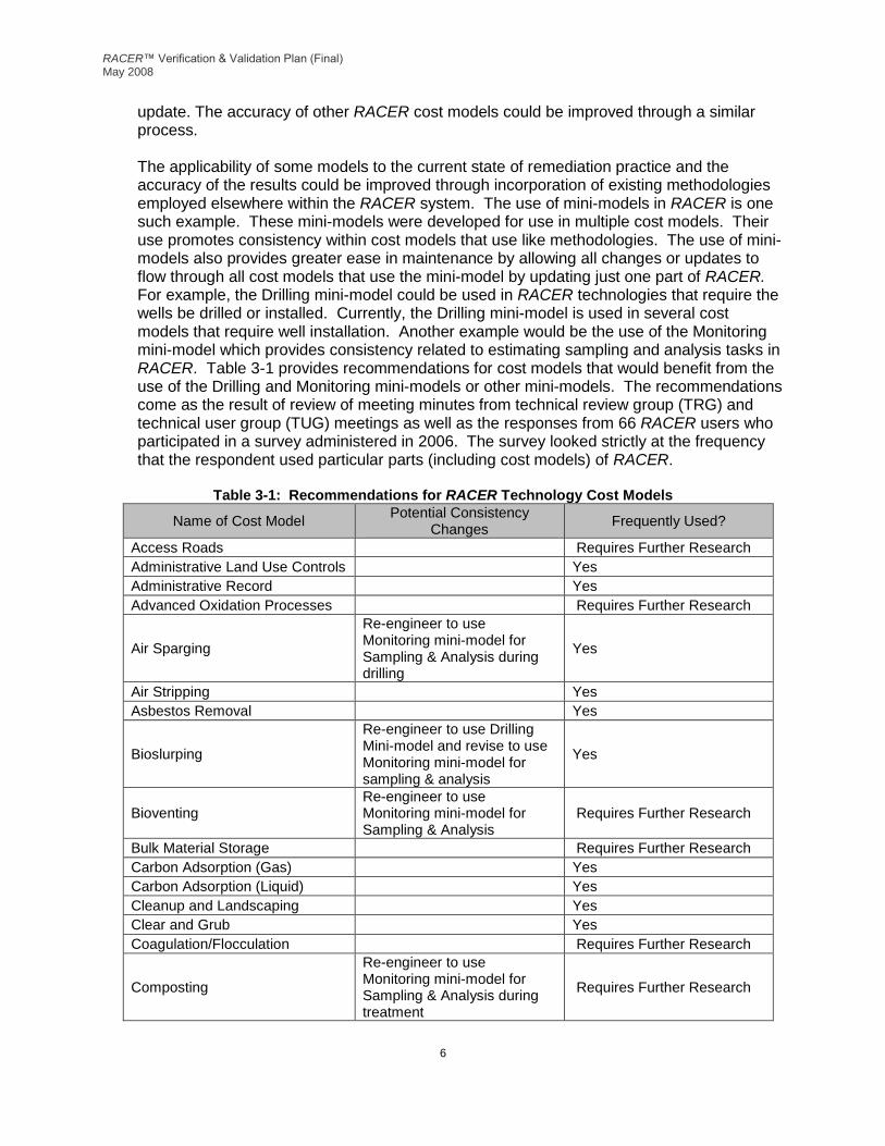
update. The accuracy of other RACER cost models could be improved through a similar process. The applicability of some models to the current state of remediation practice and the accuracy of the results could be improved through incorporation of existing methodologies employed elsewhere within the RACER system. The use of mini-models in RACER is one such example. These mini-models were developed for use in multiple cost models. Their use promotes consistency within cost models that use like methodologies. The use of mini-models also provides greater ease in maintenance by allowing all changes or updates to flow through all cost models that use the mini-model by updating just one part of RACER. For example, the Drilling mini-model could be used in RACER technologies that require the wells be drilled or installed. Currently, the Drilling mini-model is used in several cost models that require well installation. Another example would be the use of the Monitoring mini-model which provides consistency related to estimating sampling and analysis tasks in RACER. Table 3-1 provides recommendations for cost models that would benefit from the use of the Drilling and Monitoring mini-models or other mini-models. The recommendations come as the result of review of meeting minutes from technical review group (TRG) and technical user group (TUG) meetings as well as the responses from 66 RACER users who participated in a survey administered in 2006. The survey looked strictly at the frequency that the respondent used particular parts (including cost models) of RACER.
Table 3-1: Recommendations for RACER Technology Cost Models
Name of Cost Model Potential Consistency
Changes Frequently Used?
Access Roads Requires Further Research
Administrative Land Use Controls Yes
Administrative Record Yes
Advanced Oxidation Processes Requires Further Research
Air Sparging
Re-engineer to use Monitoring mini-model for Sampling & Analysis during drilling
Yes
Air Stripping Yes
Asbestos Removal Yes
Bioslurping
Re-engineer to use Drilling Mini-model and revise to use Monitoring mini-model for sampling & analysis
Yes
Bioventing Re-engineer to use Monitoring mini-model for Sampling & Analysis
Requires Further Research
Bulk Material Storage Requires Further Research
Carbon Adsorption (Gas) Yes
Carbon Adsorption (Liquid) Yes
Cleanup and Landscaping Yes
Clear and Grub Yes
Coagulation/Flocculation Requires Further Research
Composting
Re-engineer to use Monitoring mini-model for Sampling & Analysis during treatment
Requires Further Research

RACER™ Verification & Validation Plan (Final) May 2008
7
Name of Cost Model Potential Consistency
Changes Frequently Used?
Corrective Measures Study
Re-engineer to include "data gap sampling & analysis" similar to Feasibility Study model (use Monitoring mini-model to do this)
Yes for RCRA actions
D&D, Conduit, Pipe & Ductwork Yes
D&D, Contaminated Building Materials
Yes
D&D, Final Status Survey Re-engineer to Use Current Weighted Productivity Loss Factor (WTPLF) Methodology
Yes
D&D, Rad Contaminated Building Yes
D&D, Removal, Attached Hazardous Materials
Yes
D&D, Removal, Unattached Hazardous Materials
Yes
D&D, Sampling and Analysis Re-engineer to Use Current WTPLF Methodology
Yes
D&D, Site Characterization Survey
Re-engineer to Use Current WTPLF Methodology
Yes
D&D, Size Reduction Yes
D&D, Specialty Process Equipment
Yes
D&D, Surface Decontamination Yes
Decontamination Facilities Yes
Demolition, Buildings Re-engineer to use Load & Haul mini-model
Yes
Demolition, Catch Basins/Manholes
Occasionally in FUDS BD/DR
Demolition, Curbs Occasionally in FUDS BD/DR
Demolition, Fencing Occasionally in FUDS BD/DR
Demolition, Pavements Occasionally in FUDS BD/DR
Demolition, Sidewalks Occasionally in FUDS BD/DR
Demolition, Underground Pipes Occasionally in FUDS BD/DR
Dewatering (Sludge) Yes
Discharge to POTW Yes
Drum Staging
Re-engineer to use Monitoring mini-model for Sampling & Analysis for characterizing drummed wastes
Requires Further Research
Ex Situ Bioreactors Requires Further Research
Ex Situ Land Farming Requires Further Research
Ex Situ Solidification/Stabilization Requires Further Research
Ex Situ Vapor Extraction Requires Further Research
Fencing Requires Further Research
Five-Year Review Yes
Free Product Removal Yes
French Drain

RACER™ Verification & Validation Plan (Final) May 2008
8
Name of Cost Model Potential Consistency
Changes Frequently Used?
Groundwater Extraction Wells
Re-engineer to use Monitoring mini-model for Sampling & Analysis during drilling and the Drilling mini-model
Yes
Groundwater Monitoring Well
Re-engineer to use Monitoring mini-model for Sampling & Analysis during drilling
Yes
Heat Enhanced Vapor Extraction
Re-engineer to use Monitoring mini-model for Sampling & Analysis during drilling and the Drilling mini-model
Requires Further Research
In Situ Land Farming Requires Further Research
In Situ Solidification Requires Further Research
Infiltration Gallery
Re-engineer to use Monitoring mini-model for Sampling & Analysis during drilling and the Drilling mini-model (and to interact with Well Abandonment)
Requires Further Research
Injection Wells
Re-engineer to use Monitoring mini-model for Sampling & Analysis for characterizing drummed wastes
Requires Further Research
Load and Haul Yes (as a mini-model in numerous other "parent" models)
Low Level Rad Soil Treatment Requires Further Research
MEC Archives Search Report Requires Further Research
MEC Institutional Controls
Determine whether this model should be consistent with the Administrative Land Use Controls model
Yes
MEC Monitoring Yes
MEC Removal Action Yes
MEC Sifting Yes
MEC Site Characterization & Removal Assessment
Yes
Media Filtration Requires Further Research
Metals Precipitation Yes
Miscellaneous Field Installation Requires Further Research
MMRP Supplemental Investigation
Restricted to authorized users No
Natural Attenuation Revise to use Monitoring Mini-model
Yes
Neutralization Requires Further Research

RACER™ Verification & Validation Plan (Final) May 2008
9
Name of Cost Model Potential Consistency
Changes Frequently Used?
Off-site Transportation and Thermal Treatment
Re-engineer to use T&D logic and algorithms as in the Residual Waste Management model
Requires Further Research
Oil/Water Separation Yes
On-site Incineration Requires Further Research
On-site Low Temp. Thermal Desorption
Requires Further Research
Operations & Maintenance Yes
Overhead Electrical Distribution Yes
Parking Lots Requires Further Research
Passive Water Treatment Requires Further Research
Permeable Barriers Yes
Petroleum UST Site Assessment
Re-engineer to use Monitoring mini-model, and Drilling mini-model and interaction with Well Abandonment model)
Yes
Phytoremediation Re-engineer to use Monitoring mini-model for Sampling & Analysis
Yes
Preliminary Assessment Requires Further Research
RCRA Facility Investigation Re-engineer to use Monitoring mini-model for Sampling & Analysis
Yes for RCRA actions
Remedial Design Requires Further Research
Restoration Advisory Board Requires Further Research
Resurfacing Roadways/Parking Lots
Requires Further Research
Sanitary Sewer Consider retiring since system includes Discharge to POTW
No
Site Close-Out Documentation Yes
Site Inspection Re-engineer to use Monitoring mini-model for Sampling & Analysis
Yes
Slurry Walls Yes
Soil Flushing Requires Further Research
Soil Vapor Extraction
Re-engineer to use Monitoring mini-model for Sampling & Analysis during drilling
Yes
Soil Washing Requires Further Research
Special Well Drilling & Installation
Re-engineer to use Monitoring mini-model for Sampling & Analysis during drilling and the Drilling mini-model
Requires Further Research
Sprinkler System Requires Further Research
Storage Tank Installation Requires Further Research
Storm Sewer Requires Further Research
RACER™ Verification & Validation Plan (Final) May 2008
10
Name of Cost Model Potential Consistency
Changes Frequently Used?
Thermal & Catalytic Oxidation Yes
Transportation
A number of technologies in the RACER system include the need for transportation of wastes. Each model handles that need in a differing manner, although the requirements are very similar or identical. Transportation is currently available as a technology and is in use as a mini-model in the Storage Tank Installation technology. A number of other models would benefit from a consistent approach to use of Transportation as a mini-model so that a consistent methodology is used throughout the RACER system.
Requires Further Research
Trenching/Piping Yes (as a mini-model in numerous other "parent" models
User Defined Estimate Yes
UXO Scrap Removal Determine whether this model is used by the USAF
Restricted to Authorized USAF Users
UXO Active Range Clearance Planning
Determine whether this model is used by the USAF
Requires Further Research
UXO Active Target Clearance Determine whether this model is used by the USAF
Requires Further Research
Water Storage Tanks Requires Further Research
4. Suggested Enhancements In addition to the deficiencies in RACER there are opportunities for enhancements which would provide improved functionality. While the enhancements discussed in the section would allow for improved functionality, it is Earth Tech’s opinion that the deficiencies discussed in sections 3-3.3 of this plan should receive priority over the enhancements listed in this section.
4.1. Export Capabilities Currently RACER does not allow for export of estimates to detailed estimating software programs such as Micro-Computer Aided Cost Estimating System (M-CACES) Second Generation (MII) and SuccessEstimator. The capability that has been proposed in the past remains the same: to develop an interface that sends assembly level data from the RACER database to an intermediary file that can be imported into the detailed estimating software to allow for further refinement of the estimate. This capability presently exists within the

RACER™ Verification & Validation Plan (Final) May 2008
11
PArametric Cost Estimating System (PACES™) that is maintained by Earth Tech; allowing for easy access to the applicable software code and design information.
4.2. Agency Information Management Systems Interface RACER provides a valuable means by which a number of governmental agencies develop budgetary cost estimates, and in some cases, upload their estimates into information management systems. RACER meets agency-specific cost estimation needs through a wide variety of cost models that allow estimators to develop estimates based on descriptive parameters. Two groups of users, the USAEC and USACE currently are able to transfer cost data from RACER into data files that can be uploaded into their respective information management systems. Such an interface previously existed for the USAF. USAF RACER users who use the Air Force Restoration Information Management System (AFRIMS) system currently enter data into the system manually. A capability similar to what is available to USAEC and USACE users could be redeveloped to prepare data for uploading to AFRIMS. An interface capability provides automated quality control (QC) checks, consistency with agency business processes, an audit trail, and reduced human error.
5. Suggested Prioritization of Deficiency Remedies
Below is a table which displays a suggested prioritization for implementation of RACER deficiencies and enhancements discussed in this V&V Plan. Deficiencies are prioritized as high, moderate, and low. The designations have been made based on whether the deficiency would prohibit RACER operability and/or number of users who would benefit from a remedy for each respective deficiency.
Table 5-2: Suggested Prioritization of Remedies for RACER Deficiencies
Deficiency Priority Rationale
Unsupported Configuration (VB 6)
High Potentially prohibits operability Potentially impacts all users (DoD and other)
Compatibility with MS Windows Vista
High Potentially prohibits operability Potentially impacts only MS Windows Vista users
Limitations of MS Access Database Backend
High Potentially prohibits operability Potentially impacts all users (DoD and other)
MS Excel incompatible with RACER Active Reports
High Prohibits operability Impacts all users (DoD and other)

RACER™ Verification & Validation Plan (Final) May 2008
12
Deficiency Priority Rationale
Lack of Consistency in Cost Models that use Like-Methodologies
Moderate Use of mini-models provides greater ease in maintenance by allowing all changes or updates to flow thorough all cost models that use the mini-model by updating just one part of RACER
RACER™ Verification & Validation Plan (Final) May 2008
13
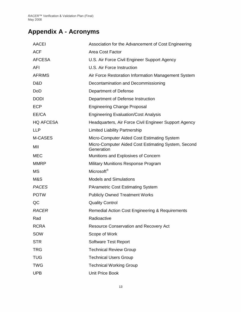
Appendix A - Acronyms
AACEI Association for the Advancement of Cost Engineering
ACF Area Cost Factor
AFCESA U.S. Air Force Civil Engineer Support Agency
AFI U.S. Air Force Instruction
AFRIMS Air Force Restoration Information Management System
D&D Decontamination and Decommissioning
DoD Department of Defense
DODI Department of Defense Instruction
ECP Engineering Change Proposal
EE/CA Engineering Evaluation/Cost Analysis
HQ AFCESA Headquarters, Air Force Civil Engineer Support Agency
LLP Limited Liability Partnership
M-CASES Micro-Computer Aided Cost Estimating System
MII Micro-Computer Aided Cost Estimating System, Second Generation
MEC Munitions and Explosives of Concern
MMRP Military Munitions Response Program
MS Microsoft®
M&S Models and Simulations
PACES PArametric Cost Estimating System
POTW Publicly Owned Treatment Works
QC Quality Control
RACER Remedial Action Cost Engineering & Requirements
Rad Radioactive
RCRA Resource Conservation and Recovery Act
SOW Scope of Work
STR Software Test Report
TRG Technical Review Group
TUG Technical Users Group
TWG Technical Working Group
UPB Unit Price Book

RACER™ Verification & Validation Plan (Final) May 2008
14
USAEC U.S. Army Environmental Command
USACE U.S. Army Corps of Engineers
USAF U.S. Air Force
UST Underground Storage Tank
UXO Unexploded Ordnance
VB Visual Basic®
V&V Verification & Validation
VV&A Verification, Validation and Accreditation
WBS Work Breakdown Structure
WBS-ECES Work Breakdown Structure - Environmental Cost Element Structure
WTPLF Weighted Productivity Loss Factor

RACER™ Verification & Validation Plan (Final) May 2008
15
Appendix B - Significant Changes to the RACER System Since RACER 2002 New Features and Changes in RACER 2002
Ability for users to easily use multiple databases
New stand-alone Operations & Maintenance phase
Per diem rates adjusted for location
New UXO Active Range Planning technology model
New UXO Active Range Clearance technology model
New UXO Scrap Recovery and Disposal technology model (available only to authorized United States Air Force users)
New Residual Waste Management technology model
New Administrative Record technology model
New Five Year Review technology model
New Restoration Advisory Board technology model
New Site Close-out Documentation technology model
New UXO (Ordnance) Sifting technology model
Major re-engineering of the MEC Site Characterization and Removal Assessment technology model (formerly named EE/CA)
Major re-engineering of the MEC Removal Action technology model
Updated Contaminated Building Materials technology model
Updated Final Status Survey technology model
Updated Site Characterization Survey technology model
Updated Surface Decontamination technology model
Updated UST Closure Removal (previously UST Closure) technology model
Updated Drum Staging (previously Drum Removal) technology model
Updated Off Site Transport and Waste Disposal technology model New Features and Changes in RACER 2003
New Bioslurping technology model
New MEC Sifting technology model
Updated MEC Institutional Controls technology model
Updated Site Inspection technology model
New feature allows users to run reports without escalation
Update of the Interim & Remedial Action Wizard
Added technical drawings to the RACER help system for fourteen (14) existing technologies
Addition of the Conversion Calculator to RACER
New Tab Notes Functionality
New No Markup Assembly Preference
New Template Updater Utility New Features and Changes in RACER 2004
New D&D, Conduit, Pipe & Ductwork technology model
New D&D, Rad Contaminated Building technology model
New D&D, Removal, Attached Hazardous Materials technology model
New D&D, Removal, Unattached Hazardous Materials technology model
New D&D, Size Reduction technology model

RACER™ Verification & Validation Plan (Final) May 2008
16
New D&D, Specialty Process Equipment technology model
Updated MEC Site Characterization and Removal Assessment technology model
Updated MEC Removal Action technology model
Updated Remedial Investigation technology model
Updated RCRA Facility Investigation technology model
Updated Site Inspection technology model
Updated Capping technology model
Updated Bioslurping technology model
Updated Restoration Advisory Board technology model
Updated UXO Active Range Planning technology model
Updated Remedial Design (Detail Method) technology model
Updated Residual Waste Management technology model
Updated Demolition, Buildings technology model
Updated Demolition, Pavements technology model
Updated Parking Lots technology model
Updated Resurfacing Roadway/Parking Lots technology model
Updated Sanitary Sewer technology model
Updated Trenching/Piping technology model
150 new assemblies New Features and Changes in RACER 2005
New Composting Technology
Updated In-situ Biodegradation technology model
Updated Five-Year Review technology model
Updated Bioslurping technology model
Updated Bioventing technology model
Updated Soil Vapor Extraction technology model
New Estimator Information and Reviewer Information
New functionality to use estimating templates to set up estimates at Level 2 (Site)
Made descriptions mandatory at Level 1 (Project), Level 2( Site) and Level 3 (Phase)
Integration of the stand-alone FUDS Post Processor and Army Interface Utilities into the RACER system
New Folder Level Batch Cost Over Time Report
New Phase Level Technology Cost Detail Report (With Markups) New Features and Changes in RACER 2006
New Estimate Documentation Report
New Administrative Land Use Controls Technology
New Estimating Templates
New MMRP Supplemental Investigation Technology (for USAF Users)
Sonic Drilling added as a drilling method
Conversion of the Operations & Maintenance Wizard to a technology model
New functionality to allow users to create multiple Remedial Design (percent method) phases.
New functionality to allow users to include both the Remedial Design (percent method) phase and the Remedial Design (detail method) phase in an estimate.
New functionality to displays the file path and file name for the database currently in use on the main screen
Level 1 screen converted to a tabbed format

RACER™ Verification & Validation Plan (Final) May 2008
17
New functionality to require an explanation if the user changes a location modifier
New required fields on the Level 2 (Site) screen for documentation of reference sources and the estimator’s support team.
New functionality for all technologies that have fields for analytical templates will base the default analytical template on the Primary Contaminant selected on the Level 3 (Phase) screen. Technologies that include secondary analytical templates will use the Secondary Contaminant to set the default template
New column on the Assembly Qty / $ screen to designate whether the assembly is marked up
Standardized Levels 1, 2 and 3 report headings for reports run at all levels.
More Level 3 reports made available for the RD (Percent) Phase New Features and Changes in RACER 2007
Minor changes to the Army Interface Utility
Automatic conversion of Operations and Maintenance run in Remedial Action or Removal/Interim Action phases to a new stand-alone Operations and Maintenance phase.
New Features and Changes in RACER 2008
New functionality to display direct and marked up costs at each level on the main screen
New File menu items for “Save As” and “Copy Database”
New File menu items listing up to four recently used databases
Completely revised markup process and markup template format
New comments fields added to Location Modifiers, Safety Levels, Productivity, Markup Template, Analysis Rate, Analytical Template and Professional Labor Rate preferences screens
Default values added to the Level Names, Safety Level, Productivity preferences screens
New report including all preferences
Preferences reports available on the main reports screen
System rate added to Analysis Rates Group and Professional Labor Rate Groups Preferences reports
Added 8 new analytical templates
Updated 21 analytical templates
Eliminated the obsolete Army Analytical Suite analytical templates
Added Select All and Deselect All buttons to the technologies that include numerous checkboxes for task selection
Re-engineered Capping technology model
Re-engineered D&D, Contaminated Building Materials technology model
Re-engineered D&D, Surface Decontamination technology model
Re-engineered Excavation technology model
Re-engineered Feasibility Study technology model
Re-engineered In Situ Biodegradation technology model
Re-engineered Monitoring technology model
Re-engineered Operations & Maintenance technology model
Re-engineered Off-Site Transportation & Disposal technology model
Re-engineered Professional Labor Management technology model
Re-engineered Remedial Investigation technology model
Re-engineered Residual Waste Management technology model
Re-engineered UST Closure & Removal technology model

RACER™ Verification & Validation Plan (Final) May 2008
18
New Well Abandonment technology model
New Buried Drum Recovery technology model
New functionality to encrypt files exported by the Army Interface Utility
Revised functionality to prevent de-selection of Cost Database if Analysis Rates, Professional Labor Rates and/or Analytical Templates are being imported or exported
Completed conversion of assemblies with defined costs (except for those priced by USACE and USAF) to definition using Government Cost Book (formerly the Unit Price Book, or UPB) line items and crews.
New functionality to display crews when viewing assembly line items
New assembly level data reports at the Folder level, Level 1, Level 2 and Level 3
New WBS report at Level 1 and Level 2
New WBS-ECES report at Level 1 and Level 2
Elimination of the obsolete Folder Cost Summary report
Elimination of the obsolete Independent Government Estimate report
Elimination of the obsolete DD1391 Detail report
Elimination of the obsolete DD1391 Summary report
Elimination of the obsolete Air Sparged Hydrocyclone technology model
Elimination of the obsolete In Situ Vitrification technology model
Elimination of the obsolete Solvent Extraction technology model
Elimination of the obsolete Professional Labor Template preference
Addition of the Sub Bid field to assembly unit prices
Use of a single location adjustment factor. Prior RACER versions used separate factors for materials, labor and equipment.

RACER™ Verification & Validation Plan (Final) May 2008
19
Appendix C - Direct Cost Calculations Assembly prices in the Assembly Cost Database have four cost components – material, labor, equipment and sub bid costs. The cost is the national average cost. To adjust the cost for the locality selected on the Level 1 (Project) screen, RACER multiplies each component of the national average cost by a factor related to the selected location. This may result in a location-adjusted cost that is higher or lower than the national average cost. The location adjustment factor is provided by the government. If the user has overridden the assembly cost in the Assembly Cost Database preference, location adjustment factors are not applied. A few assemblies never have area cost factors applied. Examples include the per diem rate, which is adjusted for locality using other means, and the mileage reimbursement rate, which does not vary by locality. Every technology in RACER utilizes safety level cost adjustments as well. Each safety level has an associated productivity adjustment factor, which can be viewed and modified using the Safety Productivity preference screen. Safety level adjustments apply to the labor and equipment cost components. The material and sub bid cost components are not adjusted for safety productivity. Some technologies that include analytical templates include adjustments for turn around time and quality control. These adjustments apply to only to assemblies in the selected analytical templates. Each selection has an associated adjustment factor. The more quickly the testing must be completed the higher the cost. Likewise, the higher level of quality control that is required, the higher the cost. Direct costs are calculated individually for each assembly when technology is run to cost. The following example illustrates the direct cost calculations: National Average assembly cost:
Material $10.00 Labor $15.00 Equipment $20.00 Sub Bid $10.00 Total $55.00
The location adjustment factor 1.05 Safety Level C Safety Productivity Adjustment:
Labor Productivity 55 Equipment Productivity 75
Turn Around Time
4 to 7 Days = 1.5 Quality Control
Level 2 = 1.1
RACER™ Verification & Validation Plan (Final) May 2008
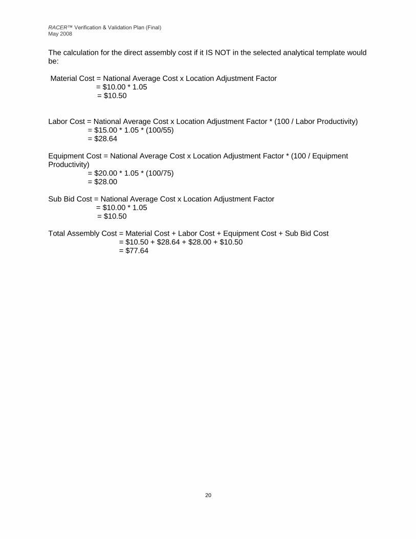
20
The calculation for the direct assembly cost if it IS NOT in the selected analytical template would be: Material Cost = National Average Cost x Location Adjustment Factor = $10.00 * 1.05 = $10.50 Labor Cost = National Average Cost x Location Adjustment Factor * (100 / Labor Productivity) = $15.00 * 1.05 * (100/55) = $28.64 Equipment Cost = National Average Cost x Location Adjustment Factor * (100 / Equipment Productivity) = $20.00 * 1.05 * (100/75) = $28.00 Sub Bid Cost = National Average Cost x Location Adjustment Factor = $10.00 * 1.05 = $10.50 Total Assembly Cost = Material Cost + Labor Cost + Equipment Cost + Sub Bid Cost = $10.50 + $28.64 + $28.00 + $10.50 = $77.64

RACER™ Verification & Validation Plan (Final) May 2008
21
The calculation for the direct assembly cost if it IS in the selected analytical template would be: Material Cost = National Average Cost x Location Adjustment Factor * Turn Around Time Factor * Quality Control Factor = $10.00 * 1.05 * 1.5 * 1.1 = $17.33 Labor Cost = National Average Cost x Location Adjustment Factor x (100 / Labor Productivity) * Turn Around Time Factor x Quality Control Factor = $15.00 * 1.05 * (100/55) * 1.5 * 1.1 = $47.25 Equipment Cost = National Average Cost x Location Adjustment Factor x (100 / Equipment Productivity) x Turn Around Time Factor x Quality Control Factor = $20.00 * 1.05 * (100/75) * 1.5 * 1.1 = $46.20 Sub Bid Cost = National Average Cost x Location Adjustment Factor x Turn Around Time Factor x Quality Control Factor = $10.00 * 1.05 * 1.5 * 1.1 = $17.33 Total Assembly Cost = Material Cost + Labor Cost + Equipment Cost + Sub Bid Cost = $17.33 + $47.25 + $46.20 + $17.33 = $128.10

RACER™ Verification & Validation Plan (Final) May 2008
22
Appendix D - Marked-up Cost Calculations Markup calculations most often performed at Level 3 (Phase) using the total costs of all the assemblies included in the technologies included in that phase. Some reports also show marked up costs for assemblies or technologies. The calculation process is the same in each instance. The following example illustrates markup calculations for a phase.
Step 1: Preliminary Calculations The total cost to be excluded from the markup routine is calculated by summing the direct cost for assemblies on the No-Markup list in all technologies in the Phase. If you used the Technology Markups window to exclude one or more technologies from the markup routine, the cost for those technologies are summed and added to the No-Markup assemblies. The equation is as follows:
Total Cost Excluded from Markup Routine = (Direct Cost for No-Markup Assemblies) + (Direct Cost for No-Markup Technologies)
For example:
Total Direct Cost of No-Markup Assemblies
= $1,000
+ Total Direct Cost for No-Markup Technology
= $2,000
Total Direct Cost Excluded from Markup
= $3,000
The cost subject to the markup routine is calculated by summing the direct cost for assemblies not on the No-Markup list in all technologies in the Phase. For example:
Total Direct Cost for Phase = $40,000
- Total Direct Cost Excluded from Markup = $3,000
Total Direct Cost to be Marked Up = $37,000
If you used the Technology Markups window to apportion costs for a technology between the Prime Contractor and Subcontractors, the technology costs are split between the Prime and Subcontractor. For example:
Total Cost for Technology to be Marked Up = $10,000
x Percentage of Work by Subcontractors = 40%
Value of Work by Subcontractors = $4,000
Value of Work by Prime Contractor = $10,000 - $4,000
= $6,000

RACER™ Verification & Validation Plan (Final) May 2008
23
Step 2: Professional Labor Overhead/G&A The Total Direct Cost for professional labor assemblies in the Phase is calculated by summing the direct cost for each assembly in Section 332201 of the RACER database. The total is split between the Prime Contractor and Subcontractors using the percentages on the Technology Markups window. The Professional Labor Overhead/G&A percentage is applied to the prime and subcontractor portions of the total direct professional labor cost for the phase to determine the prime and subcontractor professional labor overhead/G&A costs. For example:
Total Direct Cost for Section 332201 Assemblies = $2,000
x Percentage of Work by Subcontractors = 40%
Subcontractor Professional Labor Work = $800
Prime Contractor Professional Labor Work = $2,000 – $800
= $1,200
Subcontractor Professional Labor Work = $800
x Professional Labor Overhead/G&A Markup = 132%
Subcontractor Professional Labor Overhead/G&A = $1,056
Prime Contractor Professional Labor Work = $1,200
x Professional Labor Overhead/G&A Markup = 132%
Prime Contractor Professional Labor Overhead/G&A = $1,584
Step 3: Field Office Overhead/G&A The Field Office Overhead/G&A percentage is applied to the prime and sub contractor portions of the total direct cost for the phase, excluding the total direct professional labor costs, to determine the prime and subcontractor field office overhead/G&A costs. Overhead markups are not applied to SubBid items because costs for overhead are already be included in the SubBid cost. For example:
Total Direct Cost to be Marked Up = $37,000
- Total Direct Cost for Section 332201 Assemblies = $2,000
- Total SubBid Cost = $1,000
Total Direct Cost = $34,000
Total Direct Cost = $34,000
x Percentage of Work by Subcontractors = 40%
Subcontractor Direct Cost = $13,600
Prime Contractor Direct Cost = $34,000 – $13,600

RACER™ Verification & Validation Plan (Final) May 2008
24
= $20,400
Subcontractor Direct Cost = $13,600
x Field Office Overhead/G&A Markup = 25%
Subcontractor Field Office Overhead/G&A = $3,400
Prime Contractor Direct Cost = $20,400
x Field Office Overhead/G&A Markup = 25%
Prime Contractor Field Office Overhead/G&A = $5,100
Step 4: Subtotal Subcontract Costs The subcontractor professional labor overhead/G&A cost and the subcontractor field office overhead/G&A cost are added to the subcontractor total direct cost, excluding SubBid costs, to determine a subtotal subcontract cost for the phase. For example:
Subcontractor Direct Cost = $13,600
+ Subcontractor Professional Labor Overhead/G&A = $1,056
+ Subcontractor Field Office Overhead/G&A = $3,400
Subtotal Subcontract Cost = $18,056
Step 5: Subcontractor Profit The Subcontractor Profit percentage is applied to the subtotal subcontract cost to determine the subcontractor profit. For example:
Subtotal Subcontract Cost = $18,056
x Subcontractor Profit Markup = 8%
Subcontractor Profit = $1,444
Step 6: Total Subcontract Costs The subcontractor profit, subtotal contract cost, and SubBid costs are summed to determine the total subcontract cost. Subcontractor profit markups are not applied to subcontractor SubBid items because subcontractor profit is already included in the SubBid cost. For example:
Subcontractor Profit = $1,444
+ Subtotal Subcontract Cost = $18,056
+ Total SubBid Cost = $1,000
Total Subcontract Cost = $20,500

RACER™ Verification & Validation Plan (Final) May 2008
25
Step 7: Subtotal Prime Contractor Cost The subtotal prime contractor project cost for the phase is determined by summing the prime contractor total direct costs, the prime contractor professional labor overhead/G&A cost, the prime contractor field office overhead/G&A cost, and the total subcontract cost. For example:
Prime Contractor Direct Cost = $20,400
+ Prime Contractor Professional Labor Overhead/G&A = $1,584
+ Prime Contractor Field Office Overhead/G&A = $5,100
+ Total Subcontract Cost = $20,500
Subtotal Prime Contractor Cost = $47,584
Step 8: Prime Contractor Profit The Prime Profit percentage is applied to the subtotal prime contractor cost to determine the prime contractor’s profit. For example:
Subtotal Prime Contractor Cost = $47,584
x Prime Contractor Profit Markup = 8%
Prime Contractor Profit = $3,807
Step 9: Total Contract Cost
The prime profit is added to the subtotal prime contractor cost to determine the total contract cost. For example:
Prime Contractor Profit = $3,807
+ Subtotal Prime Contractor Cost = $47,584
Total Contract Cost = $51,391
Step 10: Contingency Allowance
The Contingency percentage is applied to the total contract cost to determine the contingency allowance. For example:
Total Contract Cost = $51,391
x Contingency Markup = 5%
Contingency Allowance = $2,570
Step 11: Owner Cost The Owner Cost percentage is applied to the total contract cost, including the contingency allowance, to determine the owner costs for the phase. For example:
Total Contract Cost = $51,391
+ Contingency Allowance = $2,570
x Owner Cost Markup = 11%
Owner Cost = $5,936

RACER™ Verification & Validation Plan (Final) May 2008
26
Step 12: Total Estimated Cost The total contract cost, contingency allowance, owner cost, and total no-markup costs are summed to determine the total marked-up (fully-burdened) cost for the phase. For example:
Total Contract Cost = $51,391
+ Contingency Allowance = $2,570
+ Owner Cost = $5,936
+ Total No-Markup Cost = $3,000
Total Marked-Up Cost = $62,897

RACER™ Verification & Validation Plan (Final) May 2008
27
Appendix E - Responses to Government Comments on Draft V&V Plan
RACER™ Verification & Validation Plan (Final) May 2008
28
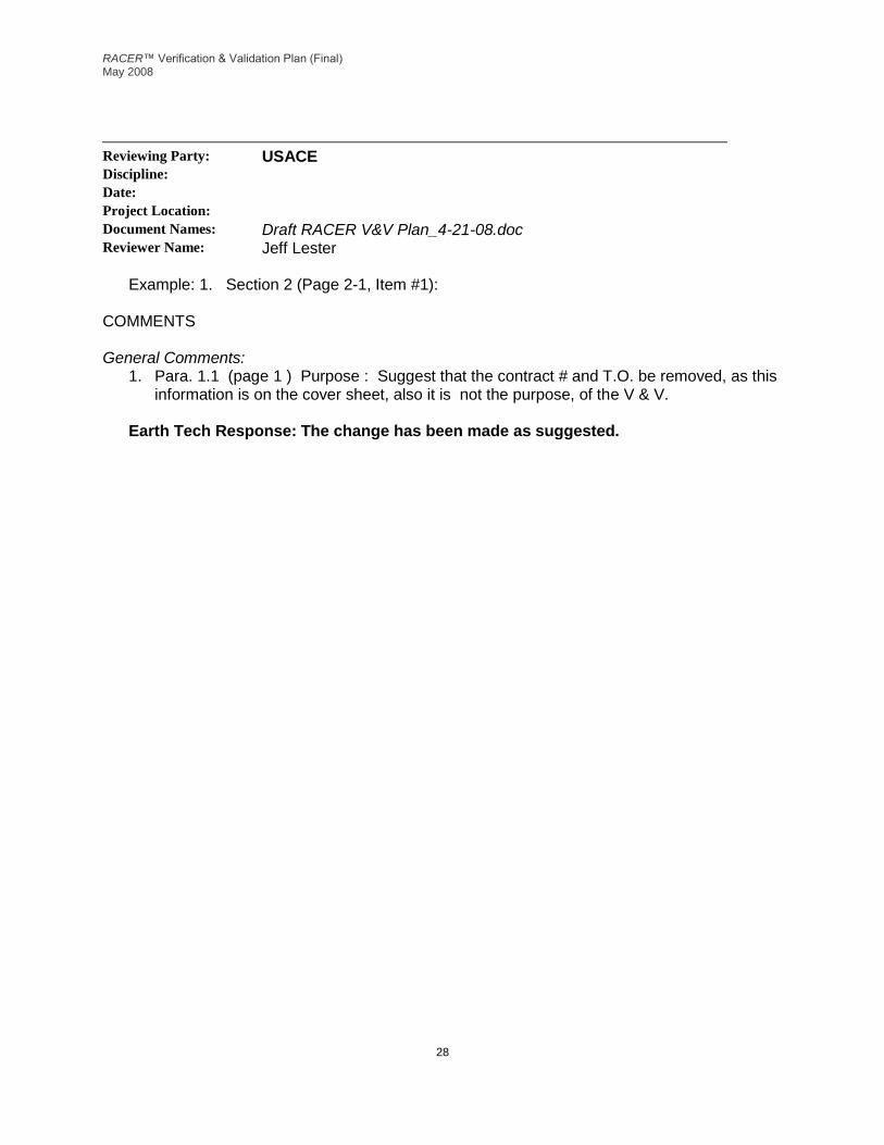
Reviewing Party: USACE Discipline: Date: Project Location: Document Names: Draft RACER V&V Plan_4-21-08.doc Reviewer Name: Jeff Lester
Example: 1. Section 2 (Page 2-1, Item #1):
COMMENTS General Comments:
1. Para. 1.1 (page 1 ) Purpose : Suggest that the contract # and T.O. be removed, as this information is on the cover sheet, also it is not the purpose, of the V & V.
Earth Tech Response: The change has been made as suggested.

RACER™ Verification & Validation Plan (Final) May 2008
29
Reviewing Party: USACE Discipline: Date: May 1, 2008 Project Location: Document Names: Draft RACER V&V Plan_4-21-08.doc Reviewer Name: Rick Osborn
Example: 1. Section 2 (Page 2-1, Item #1):
COMMENTS General Comments:
2. Specific Comments:
1.) Reference Paragraph 2.2 Testing Process. The last sentence talks about adding discussion of pre-alpha, alpha, beta, and final testing. This information was not included in the draft report was it intentionally left out? If so, please be sure to include in next submittal.
Earth Tech Response: Discussion has been added to describe the RACER testing procedures. 2.) Reference paragraph 3.1 Interface Deficiencies. The first paragraph talks about the
USACE and AEC utilities for uploading into their appropriate financial management system. The paragraph also goes on to say the Air force users do not have such a utility. I don’t view this discussion as it is written a deficiency of RACER. I would recommend not including this discussion in this section. Because Air Force does not have this utility is not a reflection of RACER a deficiency. This discussion could be reworded and used somewhere else in the document for future enhancements to the system.
Earth Tech Response: Reference to an upload utility for the USAF as a deficiency has been removed from Section 3. The discussion now occurs in Section 4, Suggested Enhancements. 3.) Reference the Paragraph 1.1 Purpose. It is stated here that this plan is to provide a
prioritization and a long-range plan for V&V activities for known deficiencies and enhancements. The document does not provide a plan as to how, or a schedule for fixing deficiencies that are listed in Table 3-1. The document does not address future enhancements to the system and a plan for incorporating them. ET has a list of enhancements from previous RACER Technical User Group meeting that could be used as a basis of what needs to be enhanced in the system. Not saying you have to use all of them but you could reasonably assess which are most important, and that would help the functionality of the system and include them in this report. As an example the discussion about including an Air Force utility for uploading into their financial management system would be a good example of an enhancement. To help in determining the schedule for model fixes and system fixes you could look at most used to least used models and schedule things that way, or look at the priority for urgent need,

RACER™ Verification & Validation Plan (Final) May 2008
30
etc. Also with schedule considerations if you do something one model of RACER that has an affect on another model of you would want schedule that together. Bottom line here is that I think the document needs to better define and schedule a long range plan for fixing true deficiencies and incorporating needed enhancements to better support the purpose of the plan.
Earth Tech Response: Reference to an upload utility for the USAF as a deficiency has been removed from Section 3. The discussion now occurs in Section 4, Suggested Enhancements. Additionally, a table has been included in Section 5, Suggested Prioritization of Deficiency Remedies, which prioritizes the implementation of the deficiencies discussed in Section 3, General System Deficiencies.
RACER™ Verification & Validation Plan (Final) May 2008
31
Reviewing Party: USAEC Discipline: Date: Project Location: Document Names: Draft RACER V&V Plan_4-21-08.doc Reviewer Name: Consolidated
General Comments:
3. Table 3-1 (Pages 7 to 10): What criteria were used to categorize the frequency of use and the users of the respective cost models?
Earth Tech Response: Toaddress this comment, the following sentence has been added to Section 1.1 of the Introduction, “This V&V Plan also includes information about potential future enhancements and modifications to the system, as the result of discussions at various contractual meetings and RACER user input and comment.” And this sentence has been added to Section 3.3, “The recommendations come as the result of review of meeting minutes from technical review group (TRG) and technical user group (TUG) meetings as well as the responses from 66 RACER users who participated in a survey administered in 2006. The survey looked strictly at the frequency that the respondent used particular parts (including cost models) of RACER.”
Specific Comments:
1. Section 2.0 (Page 2, paragraphs 1): Replace “as follows” with “for the intended use”.
Earth Tech Response: Change made as suggested.
2. Section 2 (Page 2, paragraph 2, 2nd bullet): Insert “DoD decision” after “…used to support the major “
Earth Tech Response: Change made as suggested.
3. Section 2.1 (Page 3, paragraph 1): Recommend replacing “The purpose of the RACER system is to develop cost estimates for environmental investigation and remediation projects pursuant to various regulatory programs and processes. “ with “The RACER system is a cost-estimating tool that accurately estimates costs for all phases of remediation.” This statement is consistent with the Help Topic and is used in many DoD RACER presentations.
Earth Tech Response: Change made as suggested.
4. Section 2.1 (Page 3, paragraph 3): Text states: “The ranges of accuracy, as stated by the Association for the Advancement of Cost Engineering (AACEI), for preliminary, order of magnitude, and definitive estimates…” yet the ranges listed in the accompanying table

RACER™ Verification & Validation Plan (Final) May 2008
32
are “preliminary (order of magnitude),” “secondary (budget),” and “definitive.” Revise the text to read: “preliminary, secondary, and definitive.”
Earth Tech Response: The text has been revised to state, “The ranges of accuracy, as stated by the Association for the Advancement of Cost Engineering (AACEI), for preliminary (order of magnitude), secondary (budget), and definitive estimates are displayed in Table 2-1.
5. Section 2.1 (Page 3, Table 3-1): The Table in Section 2 is numbered “3-1” but it should be numbered “2-1” (there is a Table 3-1 in Section 3.4). Also, change any references to the mis-numbered Table.
Earth Tech Response: The table reference has been changed to 2-1 and references to the table in the text have been changed to reflect the new number.
Also, the referenced table on page 3 (to be Table 2-1) also carries Section “2.1.1” as its header. Revise the table so that this section heading is deleted.
Earth Tech Response: The first column header has been revised and is now titled, “Description”.
6. Section 2.1 (Page 3, paragraph 5): Reference should be revised from “Army Environmental Command (AEC)”to “US Army Environmental Command (USAEC).” Ensure that the change from AEC to USAEC is carried throughout the document.
Earth Tech Response: References to AEC have been changed to USAEC throughout the document as suggested.
7. Section 2.2 (Page 4, last paragraph): The text reads: “Need to include a discussion of testing at pre-alpha, alpha, beta and final acceptance stages, with preparation and delivery of a Software Test Results (STR) report.” This paragraph should include this discussion; revise accordingly.
Earth Tech Response: Discussion has been added to describe the RACER testing procedures.
8. Section 3 (Page 5, paragraph 2, items numbered “2”): Suggest modifying the reference to “the RACER customer tracker” to reference the formal system for RACER changes (i.e., “engineering change proposals” (ECPs)) as described in the RACER Change Management Plan (v. 2.0, dated July 2007).
Earth Tech Response: The text in item 2 has been revised to state, “Engineering Change Proposals (ECPs) (suggestions or reports) made by users to the RACER technical support desk as described in section 2.5.1 of the RACER Change Management Plan (v 2.0 dated July 2007).
9. Section 3.1 (Page 5, paragraph 1): Replace “AEC” with “Army”. Recommend referring to “management systems” as “information management systems.”
RACER™ Verification & Validation Plan (Final) May 2008
33
Earth Tech Response: References to AEC have been changed to USAEC throughout the document as suggested. All references to “management systems” have been changed to “information management systems” as suggested.
10. Section 3.3 (Page 5, paragraph 1): Recommend adding a clarifying statement to the end of the last sentence, “in order for an MS Excel report to be generated for the user.” The paragraph as it stands seems to indicate that the user must perform this copy/paste action.
Earth Tech Response: For RACER reports that currently export directly to MS Excel, the user must perform a copy/paste action. The text has been revised to state, “RACER reports must be exported to an .rtf format and then manually copied and pasted to MS Excel.”
11. Section 3.4 (Page 6, paragraph 2): The text in Section 3.4 refers to Table “4-1,” but the table below is “3-1.” Revise the text to properly reference Table 3-1.
Earth Tech Response: The text has been changed to properly reference the table as Table 3-1.
12. Section 3.4 (Page 6, Table 3-1): How is “Frequently Used?” determined? See General Comment 1 (above) for further discussion.
Earth Tech Response: Please refer to response to General Comment 1.
13. Section 3.4 (Page 6, Table 3-1): How are “Potential Consistency Changes” determined? Are these based on Technical Working Group (TWG) meetings and/or ECPs?
Earth Tech Response: Text has been added to Section 3.3 which states, “The recommendations come as the result of review of meeting minutes from technical review group (TRG) and technical user group (TUG) meetings as well as the responses from 66 RACER users who participated in a survey administered in 2006. The survey looked strictly at the frequency that the respondent used particular parts (including cost models) of RACER.”
14. Table 3-1 (Page 7, Table Items in Column “Potential Consistency Changes”): Define the acronym “WTPLF.”
Earth Tech Response: The acronym has been defined in the text as well as in Appendix A.
15. Acronyms (Page 11, Item 1): Change “Munitions and Explosive of Concern” to “Munitions and Explosives of Concern.”
Earth Tech Response: The text has been revised as suggested.


![Data Validation and Verification [Autosaved] · ON IP DATA VALIDATION, VERIFICATION AND EXCHANGE DATA VALIDATION AND VERIFICATION USING IPOBSD’S TOOLS. Data Quality Vicious Cycle](https://img.pdfslide.net/doc/110x75/5e9d0eaef4fa863d2d614a6c/data-validation-and-verification-autosaved-on-ip-data-validation-verification.jpg)