Embed Size (px)
Citation preview
RACKING TEST EVALUATION OF EN-WALL 7250 UNITIZED CURTAIN WALL
SYSTEM WITH 3M™ VHB™ STRUCTURAL GLAZING TAPE
Final Report
Submitted to:
3M Industrial Adhesives & Tapes Division 3M Center, Bldg. 220-5E-06
St. Paul, MN 55144-1000
by
Ali M. Memari, Ph.D., P.E., Professor Kenrick Hartman, Former Graduate Student
Paul A. Kremer, Research Associate
Department of Architectural Engineering The Pennsylvania State University
104 Engineering Unit A University Park, PA 16802
March 15, 2011
2
Summary Results of cyclic racking tests on two full-scale specimens of EN-WALL 7250 Unitized Curtain Wall
Gasket Seal system (EN-WALL 7250 system) are presented. The objective of the study was to determine
the performance of this type of curtain wall system under cyclic displacements and identify any type of
failure that could occur under very large drifts. The test units (specimens) had overall dimensions of 180
in. wide by 156 in. high and were comprised of nine insulated glass panels bonded to aluminum framing
with 3M™ VHB™ Structural Glazing Tape G23F. Racking tests followed the American Architectural
Manufacturers Association (AAMA) 501.6 protocol to characterize the performance of the system. Tests
were carried out in a step-wise manner in order to stop the test after each drift increment to inspect the
specimen for any damage. Tests were carried out for unrestrained and restrained end boundary conditions.
In summary, the full-scale specimens did not sustain any glass and 3M™ VHB™ Structural Glazing Tape
G23F damage when subjected to AAMA 501.6 racking tests. Some framing derailment occurred under
very high drifts when certain boundary conditions were imposed. A complete description of the unitized
system design is presented along with racking test observations of potential serviceability issues. Air
leakage tests were also performed to evaluate the serviceability performance with respect to air leakage
after large drifts were experienced by the wall system.
Disclaimer The material presented in this report is intended to provide a better understanding of the simulated seismic response of unitized curtain wall systems. The material in this report including the data and procedures shall not be relied upon under any circumstances for any specific application or actual projects without consultation by a licensed design professional experienced in the field of glazing systems design. Anyone using the material in this report assumes ALL liability resulting from such use, and the authors, Penn State University, 3M Industrial Adhesives & Tapes Division, or EN-WALL are not in any way liable for such use.
3
Table of Contents Page 1. Introduction 4
2. Description of Test Specimens 5 3. Testing Program 7 4. Test Setup and Specimen Assembly 12
5. Racking Tests 20 5.1 Specimen 1, Test 1 21 5.2 Specimen 1, Test 2 25
5.3 Specimen 2, Test 1 33 5.4 Specimen 2, Test 2 37 5.5 Specimen 2, Test 3 40 6. Discussion of the Racking Test Results 43
7. Air Leakage Tests and Results 51 8. Conclusions 48 9. References 53 Appendix A 55
4
1. Introduction
The use of structural sealant glazing (SSG) to adhere glass panes to glazing frames (Dow
Corning 2006) as an alternative to dry glazing or capturing glass pane edges at mullion pockets
with rubber gasketing has increased over the years. Furthermore, when glass is adhered to
framing using SSG, the sealants will experience shear deformation if the curtain wall system is
of stick-built type and goes through racking (Memari et al. 2006, 2010). In order to minimize the
strains in the structural sealants and the opportunity to save on labor costs through shop glazing,
unitized framing systems have become more common in recent years. In unitized systems, the
glass is shop-glazed using SSG construction to avoid job site application of structural sealant for
better quality control. Furthermore, the framing is isolated at each floor level from the framing
above through a sliding joint known as a “stack joint.” In such construction, the unitized curtain
wall at each story can slide horizontally with respect to the curtain walls of adjacent stories and
thus provide a form of seismic isolation against in-plane interstory drifts. In such cases, the wall
panel is expected to “sway” and not actually “rack” as in the stick-built systems.
Unitized systems have traditionally employed structural silicone sealants to bond the glass lite to
the frame, but double coated acrylic foam tapes have also been used as an alternative method of
bonding the glass to the frame. Structural glazing tapes allow the use of framing systems that are
very similar to those used for silicone sealants (3M 2008). According to the 3M™ VHB™
Structural Glazing Tape technical data sheet (3M 2006), “3M™ VHB™ Structural Glazing Tape
is a high performance double-coated pressure sensitive acrylic foam tape. It is used to attach
glass to metal frames in glass curtain wall systems replacing commonly used mechanical
fasteners, gaskets or structural silicone sealants. Application performance and test results
5
demonstrate the outstanding durability, UV resistance and temperature performance of 3M™
VHB™ Tape acrylic foam chemistry.” Few studies have been conducted to evaluate the seismic
performance of unitized curtain wall systems, and this report represents one of the first full-scale
experimental simulated seismic studies on this type of unitized systems with structural glazing
tape. Testing for this pilot study consisted of cyclic racking tests on two EN-WALL 7250
unitized wall system specimens using 3M™ VHB™ Structural Glazing Tape G23F to form the
structural seals. Racking tests followed the AAMA 501.6 test protocol (AAMA 2009), and were
carried out in a step-wise manner to better characterize the performance of the system by
allowing thorough inspection of the specimens for any damage between each step. Although the
AAMA 501.6 protocol focuses on the occurrence of glass fallout, additional information related
to seal damage and frame damage were also collected. The objective of the study was to determine
the performance of this type of curtain wall system under imposed cyclic displacements and identify any
type of failure that could occur under very large drifts. In this report, a complete description of the
unitized system design is presented along with the racking test as well as air leakage test results.
2. Description of Test Specimens
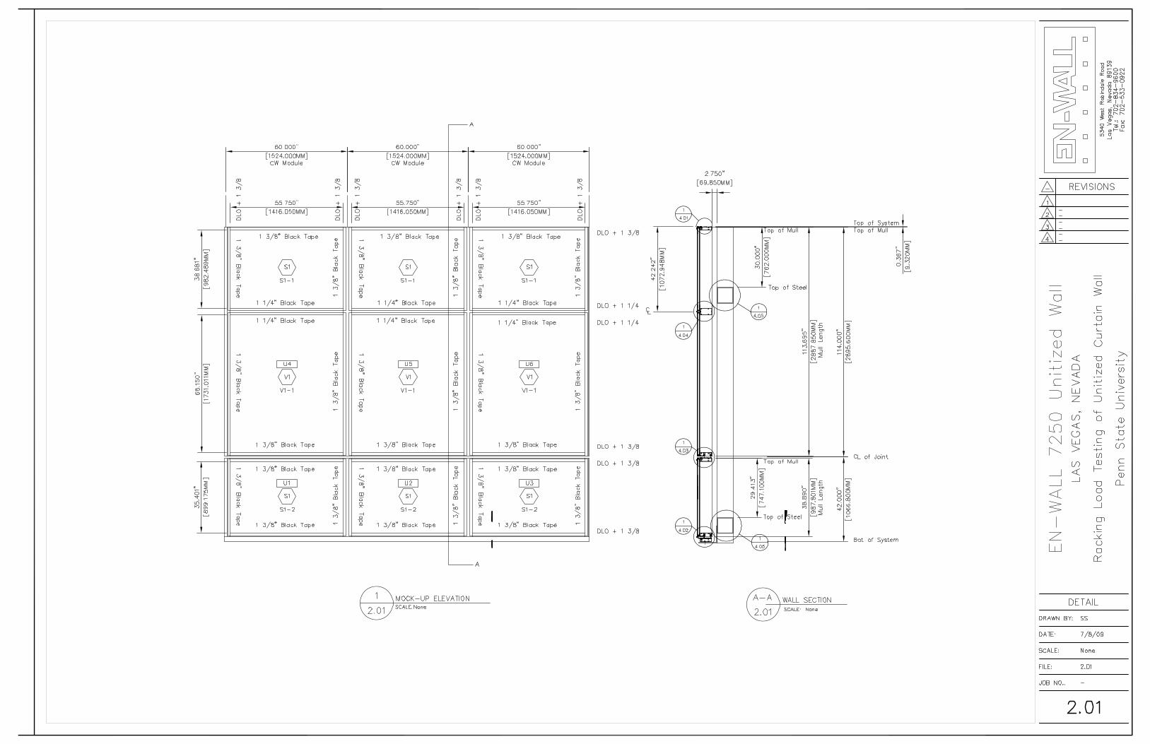
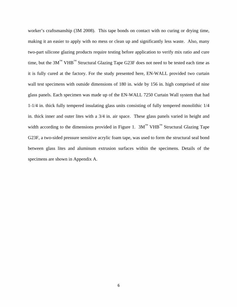
The test specimen shown in Figure 1 was comprised of six (6) EN-WALL 7250 Curtain Wall
Units (U1-U6) containing nine (9) glass lites positioned three panes high and three panes wide.
The configuration simulated a story height in a typical commercial building with two spandrel
areas and a section for vision glass. 3M Industrial and Adhesives and Tape Division (3M) has
developed 3M™ VHB™ Structural Glazing Tape G23F as an alternative to wet and dry glazing.
Rather than applying a thick liquid silicone sealant bead to the perimeter of the glass, 3M™
VHB™ Structural Glazing Tape G23F structural glazing tape performs like a peel and stick
adhesive sealant, resulting in much cleaner and quicker assembly that does not rely as much on a
6
worker’s craftsmanship (3M 2008). This tape bonds on contact with no curing or drying time,
making it an easier to apply with no mess or clean up and significantly less waste. Also, many
two-part silicone glazing products require testing before application to verify mix ratio and cure
time, but the 3M™ VHB™ Structural Glazing Tape G23F does not need to be tested each time as
it is fully cured at the factory. For the study presented here, EN-WALL provided two curtain
wall test specimens with outside dimensions of 180 in. wide by 156 in. high comprised of nine
glass panels. Each specimen was made up of the EN-WALL 7250 Curtain Wall system that had
1-1/4 in. thick fully tempered insulating glass units consisting of fully tempered monolithic 1/4
in. thick inner and outer lites with a 3/4 in. air space. These glass panels varied in height and
width according to the dimensions provided in Figure 1. 3M™ VHB™ Structural Glazing Tape
G23F, a two-sided pressure sensitive acrylic foam tape, was used to form the structural seal bond
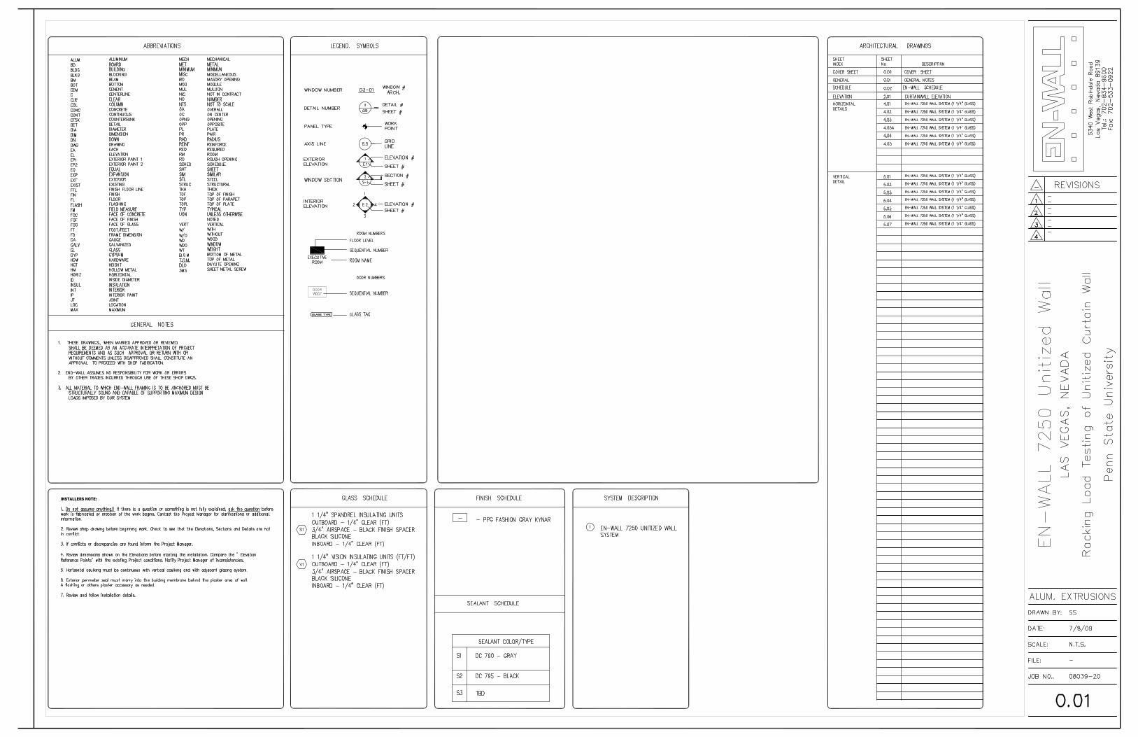
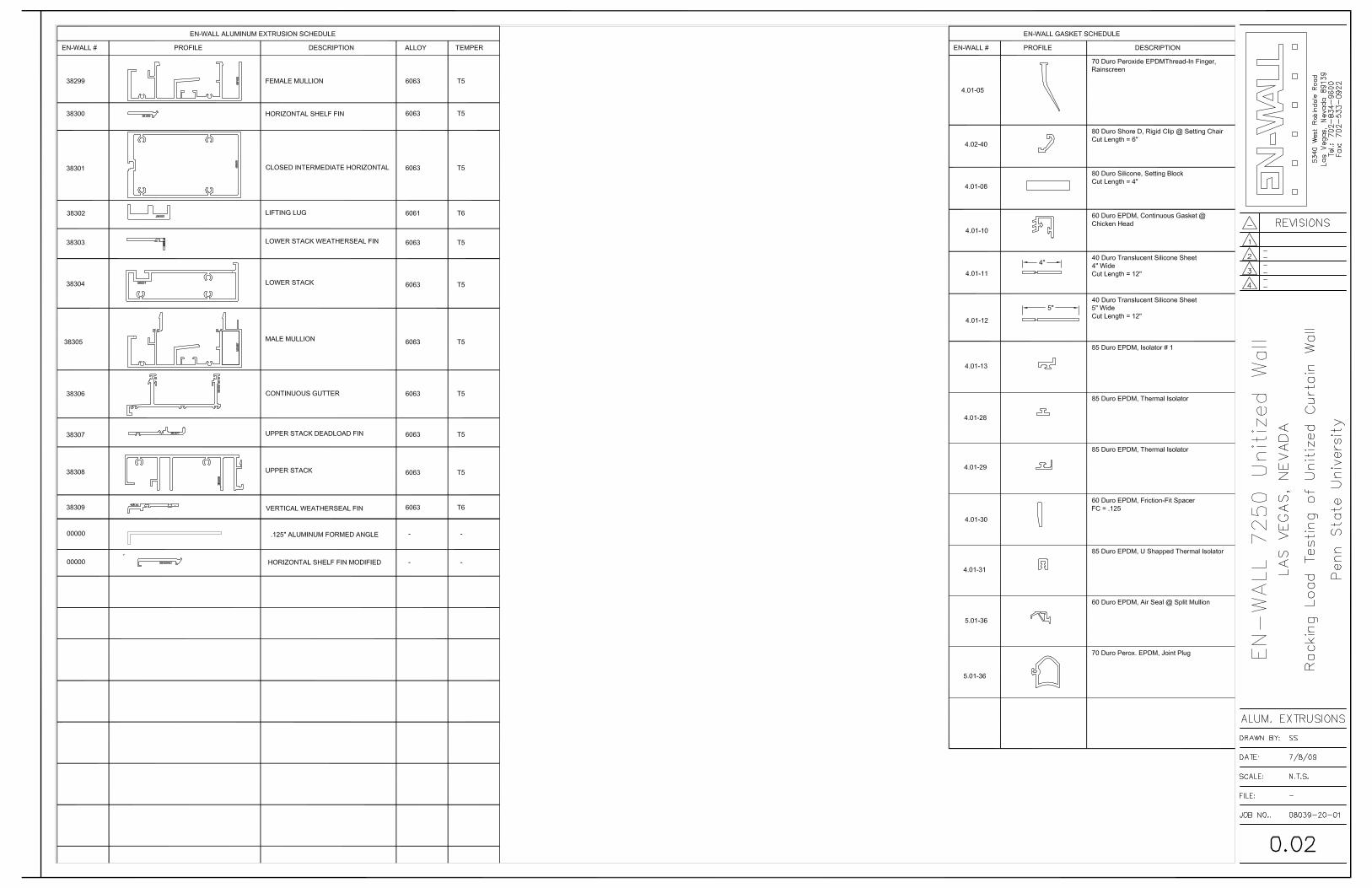
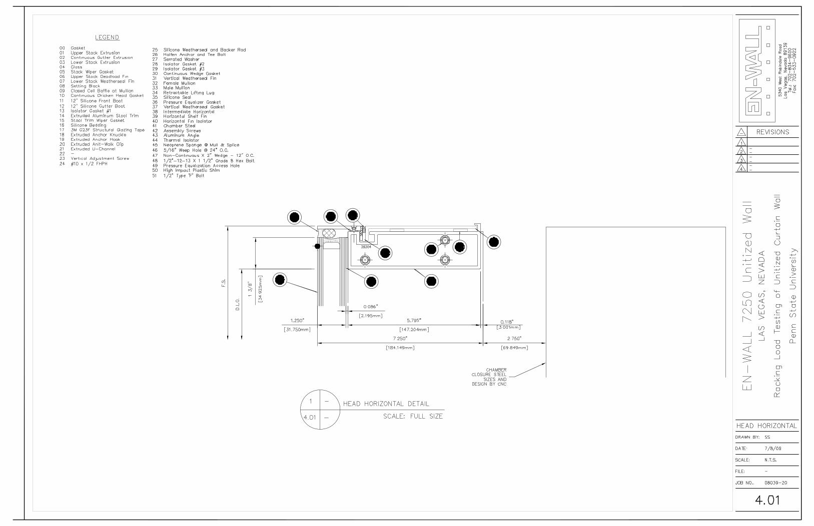
between glass lites and aluminum extrusion surfaces within the specimens. Details of the
specimens are shown in Appendix A.
7
Figure 1- Unitized System (EN-WALL)
3. Testing Program
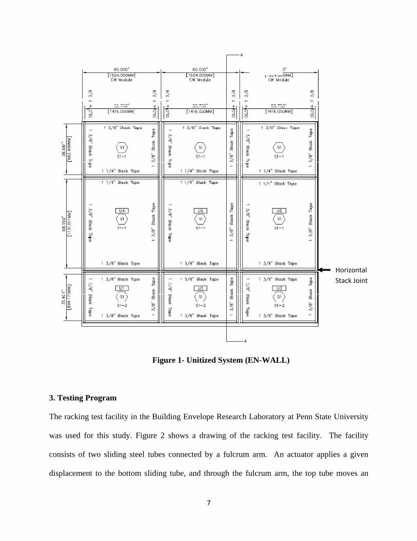
The racking test facility in the Building Envelope Research Laboratory at Penn State University
was used for this study. Figure 2 shows a drawing of the racking test facility. The facility
consists of two sliding steel tubes connected by a fulcrum arm. An actuator applies a given
displacement to the bottom sliding tube, and through the fulcrum arm, the top tube moves an
Horizontal Stack Joint
8
equal displacement in the opposite direction. This motion simulates the drift a single story may
experience during an earthquake.
Figure 2 – Racking Facility
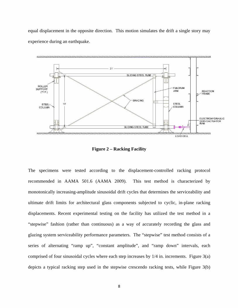
The specimens were tested according to the displacement-controlled racking protocol
recommended in AAMA 501.6 (AAMA 2009). This test method is characterized by
monotonically increasing-amplitude sinusoidal drift cycles that determines the serviceability and
ultimate drift limits for architectural glass components subjected to cyclic, in-plane racking
displacements. Recent experimental testing on the facility has utilized the test method in a
“stepwise” fashion (rather than continuous) as a way of accurately recording the glass and
glazing system serviceability performance parameters. The “stepwise” test method consists of a
series of alternating “ramp up”, “constant amplitude”, and “ramp down” intervals, each
comprised of four sinusoidal cycles where each step increases by 1/4 in. increments. Figure 3(a)
depicts a typical racking step used in the stepwise crescendo racking tests, while Figure 3(b)
9
shows the continuous time history of the crescendo test method when the steps are concatenated
and the “ramp down” intervals removed.
(a) Typical racking Step (Step 8; 0.8 Hz; 2.5% drift% Drift Index.) for AAMA 501.6 stepwise dynamic crescendo tests
(b) Entire crescendo test
Figure 3. Drift Time Histories for Crescendo Test Method
The unitized specimens were mounted directly to the steel sliding tubes spaced at ten feet to
simulate a typical floor height as shown in Figures 4 and 5. Frame-to-structure connections
designed by EN-WALL for an actual installation of the unitized wall system on a building were
used as shown in Figure 6. The connection used extruded aluminum anchor knuckles (clips)
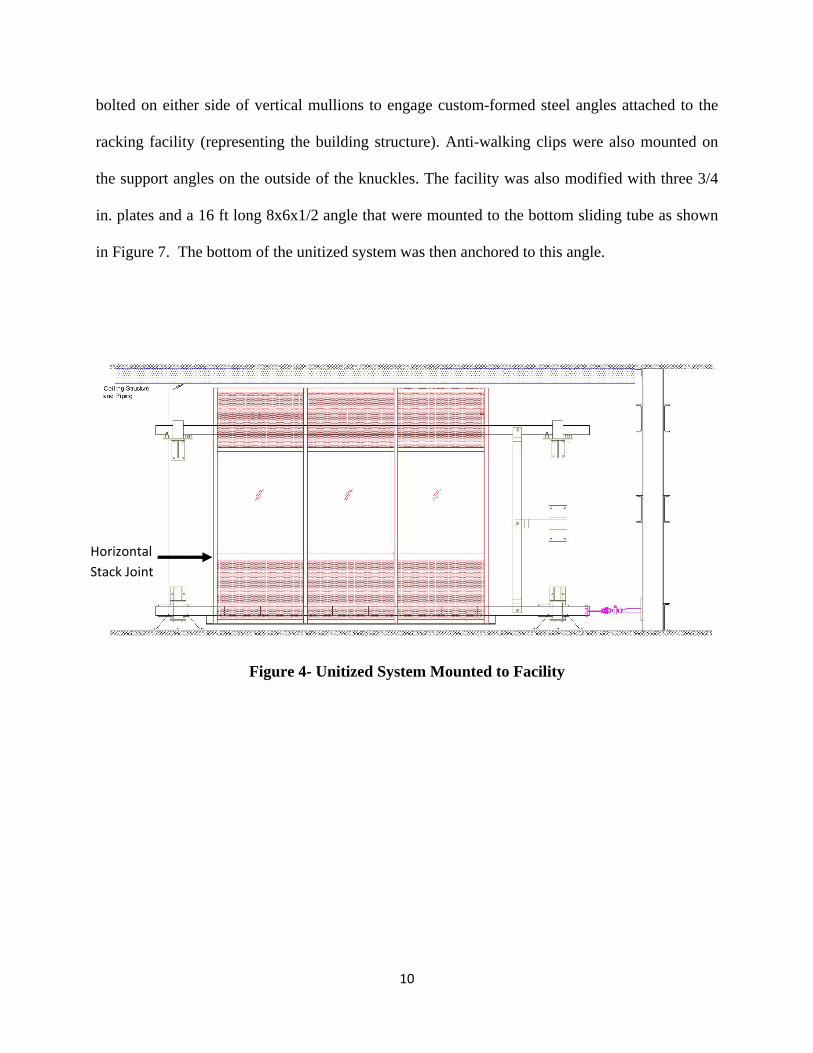
10
bolted on either side of vertical mullions to engage custom-formed steel angles attached to the
racking facility (representing the building structure). Anti-walking clips were also mounted on
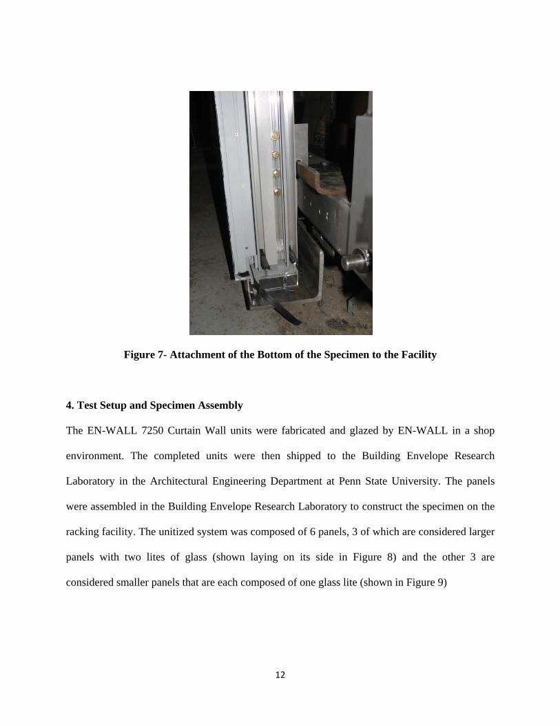
the support angles on the outside of the knuckles. The facility was also modified with three 3/4
in. plates and a 16 ft long 8x6x1/2 angle that were mounted to the bottom sliding tube as shown
in Figure 7. The bottom of the unitized system was then anchored to this angle.
Figure 4- Unitized System Mounted to Facility
Horizontal Stack Joint
11
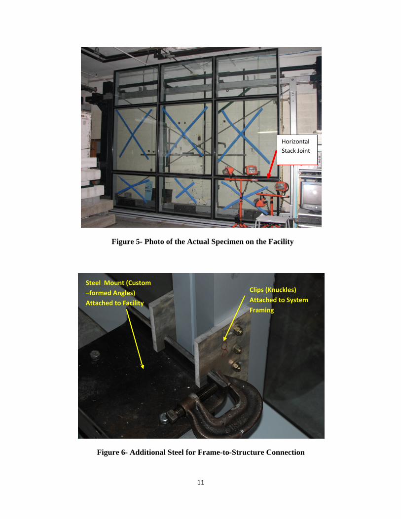
Figure 5- Photo of the Actual Specimen on the Facility
Figure 6- Additional Steel for Frame-to-Structure Connection
Clips (Knuckles) Attached to System Framing
Steel Mount (Custom –formed Angles) Attached to Facility
Horizontal Stack Joint
12
Figure 7- Attachment of the Bottom of the Specimen to the Facility
4. Test Setup and Specimen Assembly
The EN-WALL 7250 Curtain Wall units were fabricated and glazed by EN-WALL in a shop
environment. The completed units were then shipped to the Building Envelope Research
Laboratory in the Architectural Engineering Department at Penn State University. The panels
were assembled in the Building Envelope Research Laboratory to construct the specimen on the
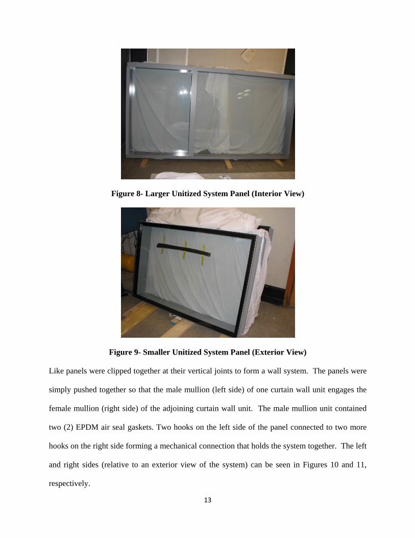
racking facility. The unitized system was composed of 6 panels, 3 of which are considered larger
panels with two lites of glass (shown laying on its side in Figure 8) and the other 3 are
considered smaller panels that are each composed of one glass lite (shown in Figure 9)
13
Figure 8- Larger Unitized System Panel (Interior View)
Figure 9- Smaller Unitized System Panel (Exterior View)
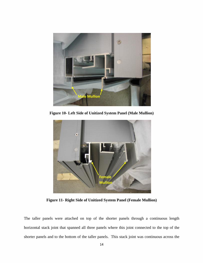
Like panels were clipped together at their vertical joints to form a wall system. The panels were
simply pushed together so that the male mullion (left side) of one curtain wall unit engages the
female mullion (right side) of the adjoining curtain wall unit. The male mullion unit contained
two (2) EPDM air seal gaskets. Two hooks on the left side of the panel connected to two more
hooks on the right side forming a mechanical connection that holds the system together. The left
and right sides (relative to an exterior view of the system) can be seen in Figures 10 and 11,
respectively.
14
Figure 10- Left Side of Unitized System Panel (Male Mullion)
Figure 11- Right Side of Unitized System Panel (Female Mullion)
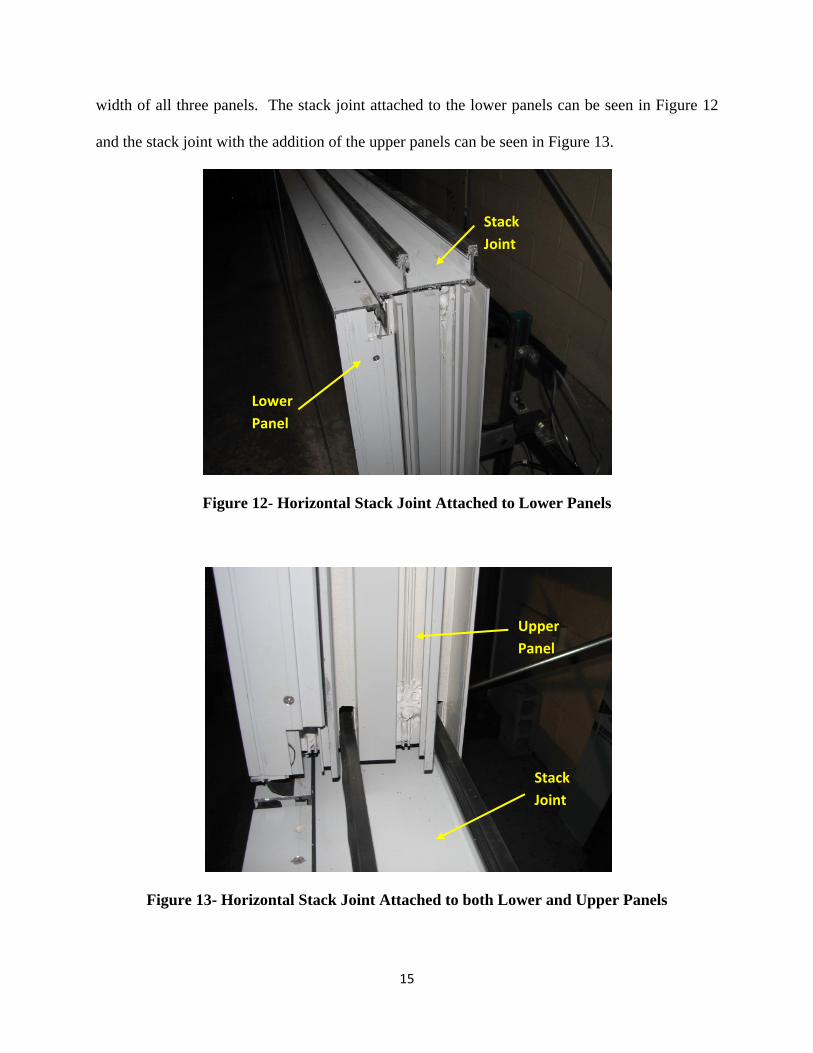
The taller panels were attached on top of the shorter panels through a continuous length
horizontal stack joint that spanned all three panels where this joint connected to the top of the
shorter panels and to the bottom of the taller panels. This stack joint was continuous across the
Male Mullion
Female Mullion
15
width of all three panels. The stack joint attached to the lower panels can be seen in Figure 12
and the stack joint with the addition of the upper panels can be seen in Figure 13.
Figure 12- Horizontal Stack Joint Attached to Lower Panels
Figure 13- Horizontal Stack Joint Attached to both Lower and Upper Panels
Stack Joint
Lower Panel
Upper Panel
Stack Joint
16
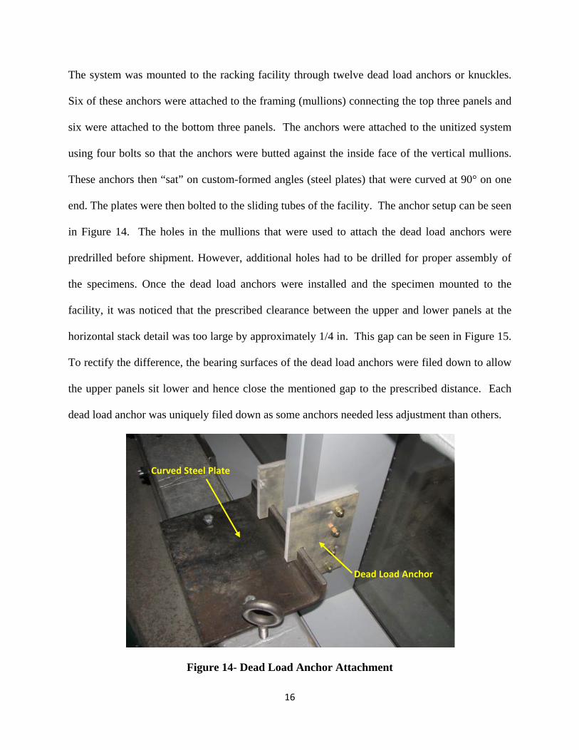
The system was mounted to the racking facility through twelve dead load anchors or knuckles.
Six of these anchors were attached to the framing (mullions) connecting the top three panels and
six were attached to the bottom three panels. The anchors were attached to the unitized system
using four bolts so that the anchors were butted against the inside face of the vertical mullions.
These anchors then “sat” on custom-formed angles (steel plates) that were curved at 90° on one
end. The plates were then bolted to the sliding tubes of the facility. The anchor setup can be seen
in Figure 14. The holes in the mullions that were used to attach the dead load anchors were
predrilled before shipment. However, additional holes had to be drilled for proper assembly of
the specimens. Once the dead load anchors were installed and the specimen mounted to the
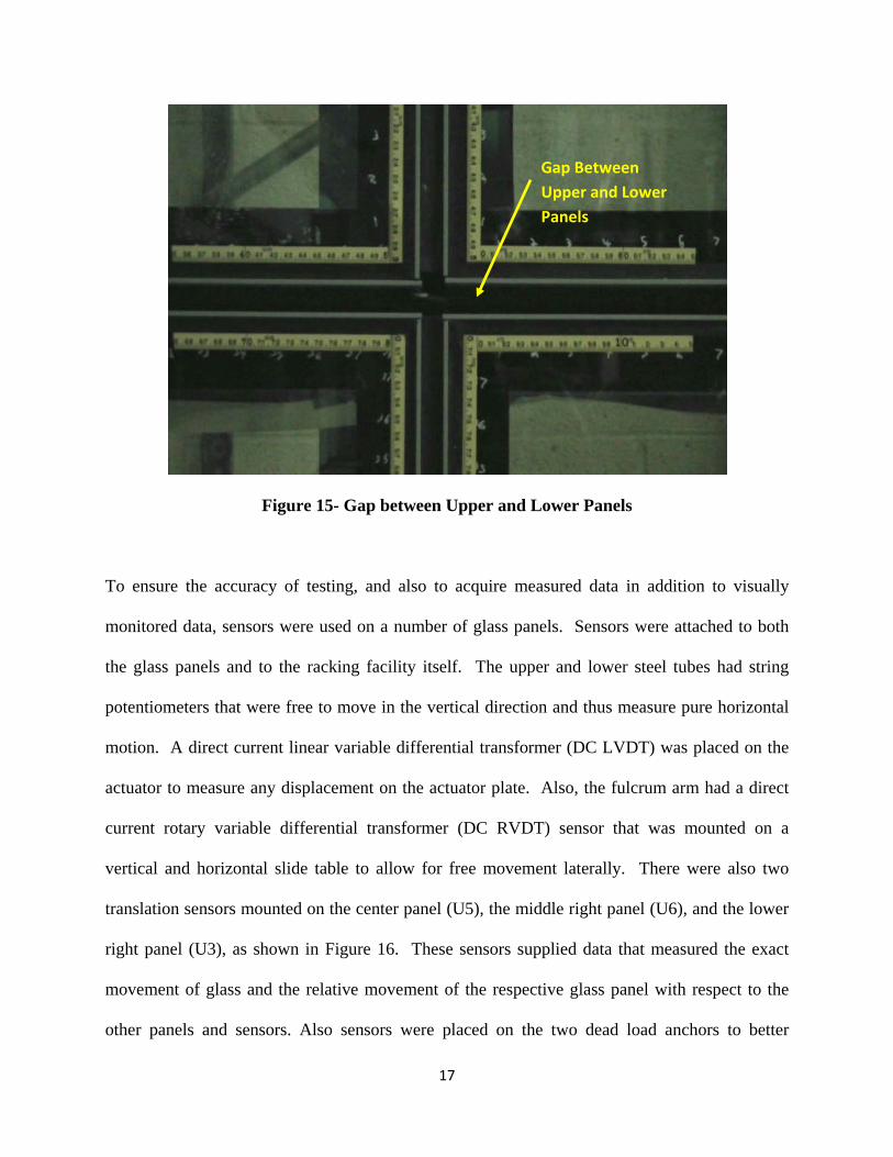
facility, it was noticed that the prescribed clearance between the upper and lower panels at the
horizontal stack detail was too large by approximately 1/4 in. This gap can be seen in Figure 15.
To rectify the difference, the bearing surfaces of the dead load anchors were filed down to allow
the upper panels sit lower and hence close the mentioned gap to the prescribed distance. Each
dead load anchor was uniquely filed down as some anchors needed less adjustment than others.
Figure 14- Dead Load Anchor Attachment
Curved Steel Plate
Dead Load Anchor
17
Figure 15- Gap between Upper and Lower Panels
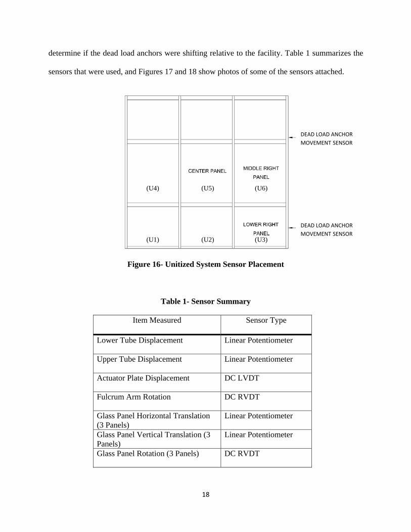
To ensure the accuracy of testing, and also to acquire measured data in addition to visually
monitored data, sensors were used on a number of glass panels. Sensors were attached to both
the glass panels and to the racking facility itself. The upper and lower steel tubes had string
potentiometers that were free to move in the vertical direction and thus measure pure horizontal
motion. A direct current linear variable differential transformer (DC LVDT) was placed on the
actuator to measure any displacement on the actuator plate. Also, the fulcrum arm had a direct
current rotary variable differential transformer (DC RVDT) sensor that was mounted on a
vertical and horizontal slide table to allow for free movement laterally. There were also two
translation sensors mounted on the center panel (U5), the middle right panel (U6), and the lower
right panel (U3), as shown in Figure 16. These sensors supplied data that measured the exact
movement of glass and the relative movement of the respective glass panel with respect to the
other panels and sensors. Also sensors were placed on the two dead load anchors to better
Gap Between Upper and Lower Panels
18
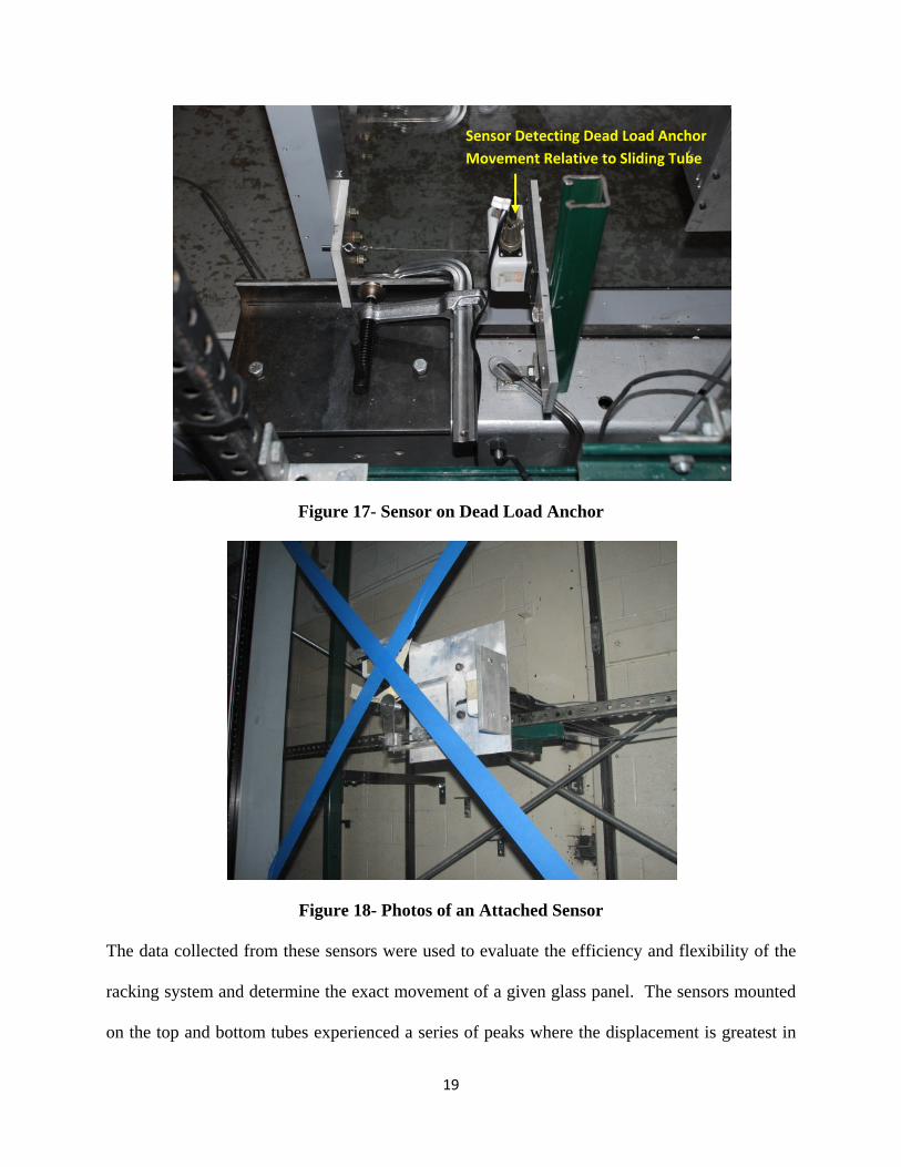
determine if the dead load anchors were shifting relative to the facility. Table 1 summarizes the
sensors that were used, and Figures 17 and 18 show photos of some of the sensors attached.
Figure 16- Unitized System Sensor Placement
Table 1- Sensor Summary
Item Measured Sensor Type
Lower Tube Displacement Linear Potentiometer
Upper Tube Displacement Linear Potentiometer
Actuator Plate Displacement DC LVDT
Fulcrum Arm Rotation DC RVDT
Glass Panel Horizontal Translation (3 Panels)
Linear Potentiometer
Glass Panel Vertical Translation (3 Panels)
Linear Potentiometer
Glass Panel Rotation (3 Panels) DC RVDT
DEAD LOAD ANCHOR MOVEMENT SENSOR
DEAD LOAD ANCHOR MOVEMENT SENSOR
(U5) (U6)
(U3)
(U4)
(U2) (U1)
19
Figure 17- Sensor on Dead Load Anchor
Figure 18- Photos of an Attached Sensor
The data collected from these sensors were used to evaluate the efficiency and flexibility of the
racking system and determine the exact movement of a given glass panel. The sensors mounted
on the top and bottom tubes experienced a series of peaks where the displacement is greatest in
Sensor Detecting Dead Load Anchor Movement Relative to Sliding Tube
20
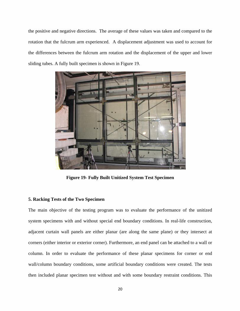
the positive and negative directions. The average of these values was taken and compared to the
rotation that the fulcrum arm experienced. A displacement adjustment was used to account for
the differences between the fulcrum arm rotation and the displacement of the upper and lower
sliding tubes. A fully built specimen is shown in Figure 19.
Figure 19- Fully Built Unitized System Test Specimen
5. Racking Tests of the Two Specimen
The main objective of the testing program was to evaluate the performance of the unitized
system specimens with and without special end boundary conditions. In real-life construction,
adjacent curtain wall panels are either planar (are along the same plane) or they intersect at
corners (either interior or exterior corner). Furthermore, an end panel can be attached to a wall or
column. In order to evaluate the performance of these planar specimens for corner or end
wall/column boundary conditions, some artificial boundary conditions were created. The tests
then included planar specimen test without and with some boundary restraint conditions. This
21
section qualitatively reviews the results of the two unitized system specimens. The first
specimen (Specimen 1) was tested twice, once without restraint at the stack joint and dead load
anchors (Test 1), and once with restraints (Test 2). The second specimen (Specimen 2) had dead
load anchor restraints and was tested three times, once without restraint at the stack joint (Test
1), and twice with two different types of restraints (Tests 2 and 3).
5.1 Specimen 1, Test 1
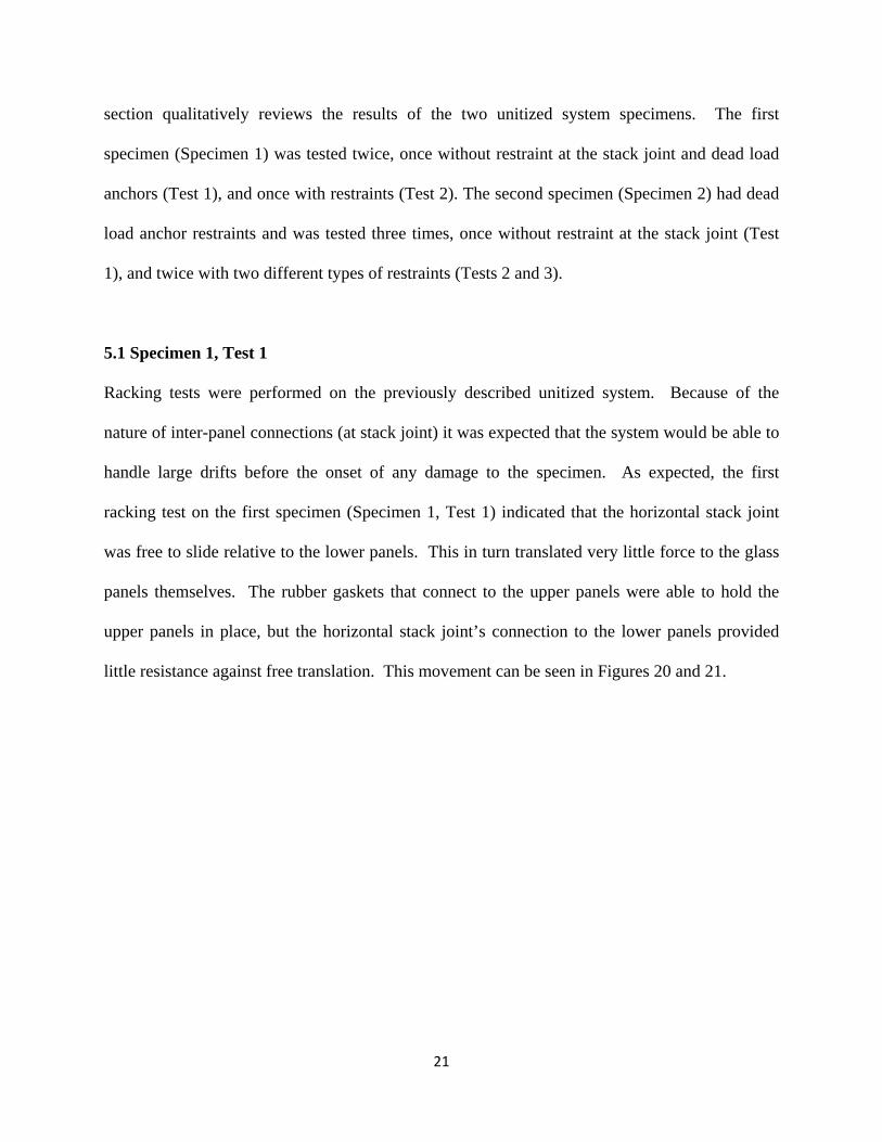
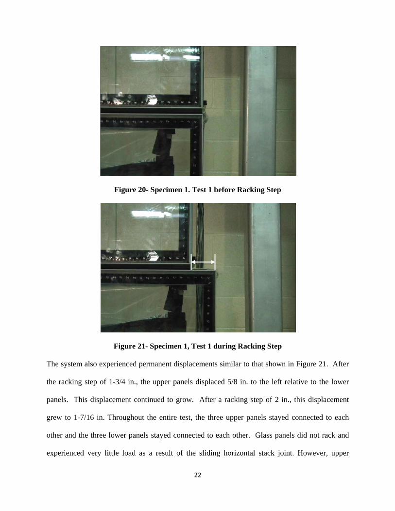
Racking tests were performed on the previously described unitized system. Because of the
nature of inter-panel connections (at stack joint) it was expected that the system would be able to
handle large drifts before the onset of any damage to the specimen. As expected, the first
racking test on the first specimen (Specimen 1, Test 1) indicated that the horizontal stack joint
was free to slide relative to the lower panels. This in turn translated very little force to the glass
panels themselves. The rubber gaskets that connect to the upper panels were able to hold the
upper panels in place, but the horizontal stack joint’s connection to the lower panels provided
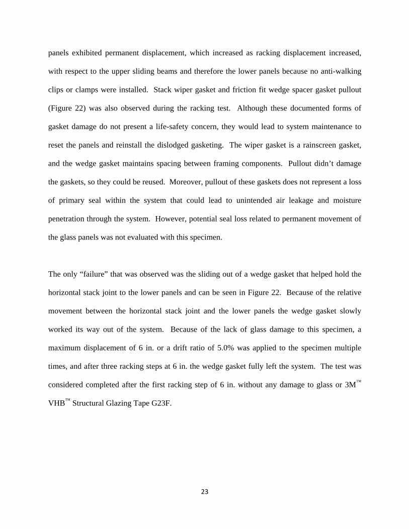
little resistance against free translation. This movement can be seen in Figures 20 and 21.
22
Figure 20- Specimen 1. Test 1 before Racking Step
Figure 21- Specimen 1, Test 1 during Racking Step
The system also experienced permanent displacements similar to that shown in Figure 21. After
the racking step of 1-3/4 in., the upper panels displaced 5/8 in. to the left relative to the lower
panels. This displacement continued to grow. After a racking step of 2 in., this displacement
grew to 1-7/16 in. Throughout the entire test, the three upper panels stayed connected to each
other and the three lower panels stayed connected to each other. Glass panels did not rack and
experienced very little load as a result of the sliding horizontal stack joint. However, upper
23
panels exhibited permanent displacement, which increased as racking displacement increased,
with respect to the upper sliding beams and therefore the lower panels because no anti-walking
clips or clamps were installed. Stack wiper gasket and friction fit wedge spacer gasket pullout
(Figure 22) was also observed during the racking test. Although these documented forms of
gasket damage do not present a life-safety concern, they would lead to system maintenance to
reset the panels and reinstall the dislodged gasketing. The wiper gasket is a rainscreen gasket,
and the wedge gasket maintains spacing between framing components. Pullout didn’t damage
the gaskets, so they could be reused. Moreover, pullout of these gaskets does not represent a loss
of primary seal within the system that could lead to unintended air leakage and moisture
penetration through the system. However, potential seal loss related to permanent movement of
the glass panels was not evaluated with this specimen.
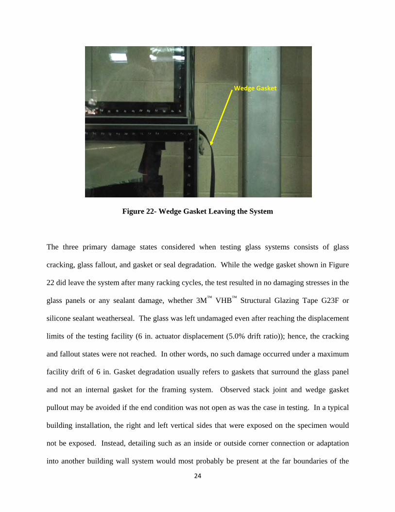
The only “failure” that was observed was the sliding out of a wedge gasket that helped hold the
horizontal stack joint to the lower panels and can be seen in Figure 22. Because of the relative
movement between the horizontal stack joint and the lower panels the wedge gasket slowly
worked its way out of the system. Because of the lack of glass damage to this specimen, a
maximum displacement of 6 in. or a drift ratio of 5.0% was applied to the specimen multiple
times, and after three racking steps at 6 in. the wedge gasket fully left the system. The test was
considered completed after the first racking step of 6 in. without any damage to glass or 3M™
VHB™ Structural Glazing Tape G23F.
24
Figure 22- Wedge Gasket Leaving the System
The three primary damage states considered when testing glass systems consists of glass
cracking, glass fallout, and gasket or seal degradation. While the wedge gasket shown in Figure
22 did leave the system after many racking cycles, the test resulted in no damaging stresses in the
glass panels or any sealant damage, whether 3M™ VHB™ Structural Glazing Tape G23F or
silicone sealant weatherseal. The glass was left undamaged even after reaching the displacement
limits of the testing facility (6 in. actuator displacement (5.0% drift ratio)); hence, the cracking
and fallout states were not reached. In other words, no such damage occurred under a maximum
facility drift of 6 in. Gasket degradation usually refers to gaskets that surround the glass panel
and not an internal gasket for the framing system. Observed stack joint and wedge gasket
pullout may be avoided if the end condition was not open as was the case in testing. In a typical
building installation, the right and left vertical sides that were exposed on the specimen would
not be exposed. Instead, detailing such as an inside or outside corner connection or adaptation
into another building wall system would most probably be present at the far boundaries of the
Wedge Gasket
25
wall system. The gasket may still pull out to some degree, but it would depend on restrictions
presented by the boundary detailing. It is clear from this first test that the stack joint and anchor
combination can minimize wall system component damage at large drifts because it does not
restrict the panels from moving. During the initial test, the horizontal stack joint was allowed
unlimited movement, while in an actual installation, detailing at the far boundaries would be
expected to affect movement capacity and perhaps damage modes in a manner not evaluated in
this initial test.
5.2 Specimen 1, Test 2
Test 2 of Specimen 1 was run using an end boundary condition to join the upper and lower
panels. Because in practical applications of unitized systems on buildings some degree of
restraint at the horizontal stack joint exists such as at corners of two perpendicular panels, it was
desired to determine the behavior of the specimen if some form of restraint was used at the
vertical edge. For this purpose, it was decided to first attach an aluminum bar to the vertical edge
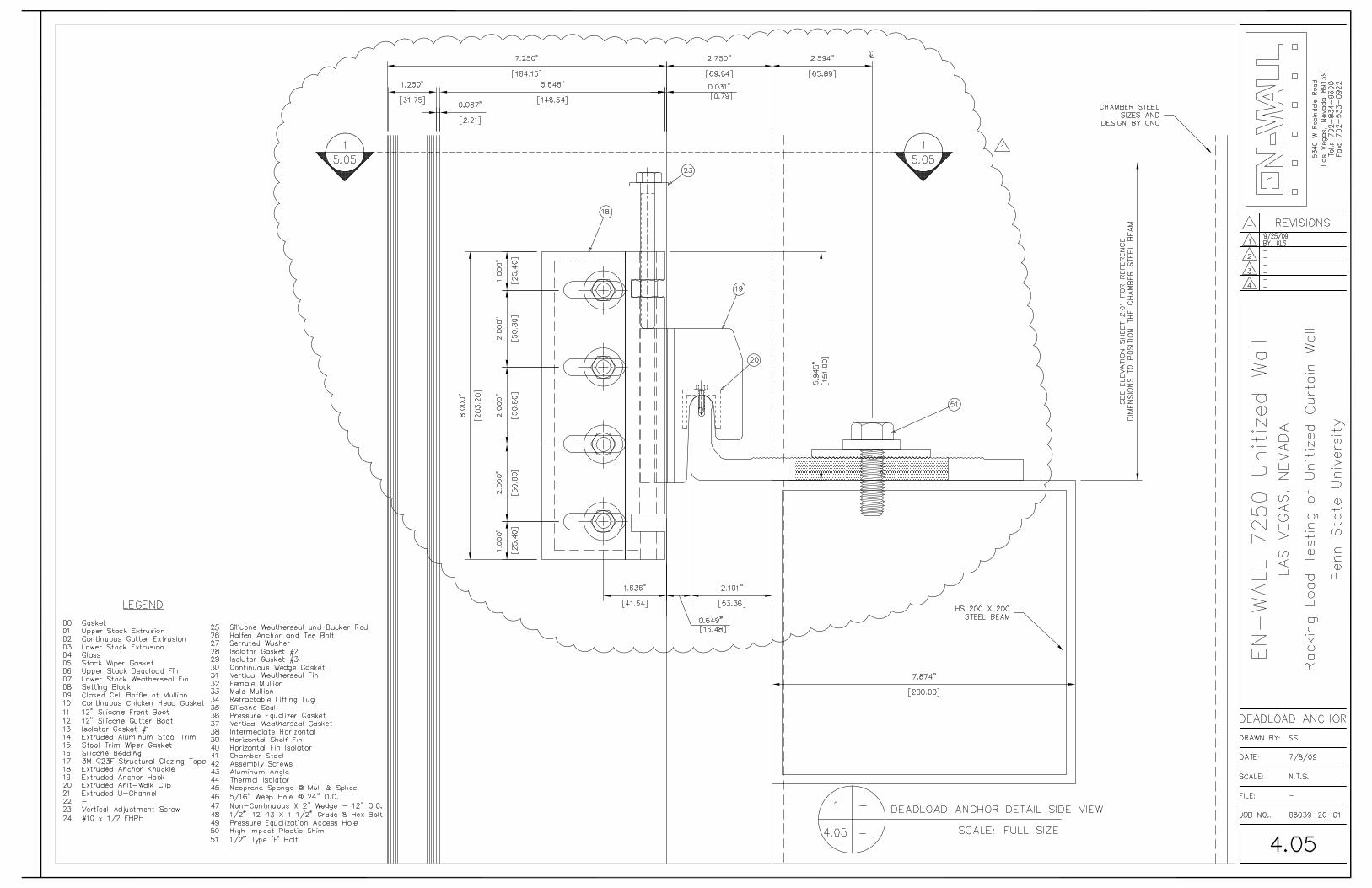
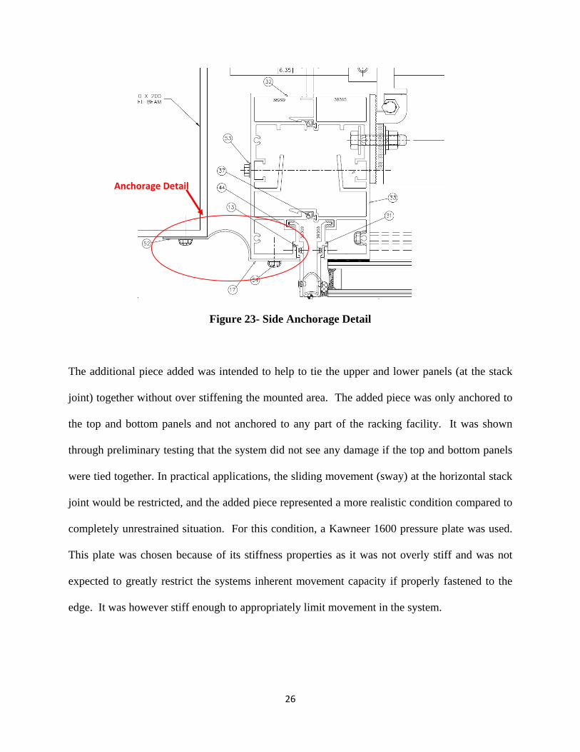
of the specimen to imitate the end detail shown in Figure 23 that shows the edge of the EN-Wall
system anchored to the structure.
26
Figure 23- Side Anchorage Detail
The additional piece added was intended to help to tie the upper and lower panels (at the stack
joint) together without over stiffening the mounted area. The added piece was only anchored to
the top and bottom panels and not anchored to any part of the racking facility. It was shown
through preliminary testing that the system did not see any damage if the top and bottom panels
were tied together. In practical applications, the sliding movement (sway) at the horizontal stack
joint would be restricted, and the added piece represented a more realistic condition compared to
completely unrestrained situation. For this condition, a Kawneer 1600 pressure plate was used.
This plate was chosen because of its stiffness properties as it was not overly stiff and was not
expected to greatly restrict the systems inherent movement capacity if properly fastened to the
edge. It was however stiff enough to appropriately limit movement in the system.
Anchorage Detail
27
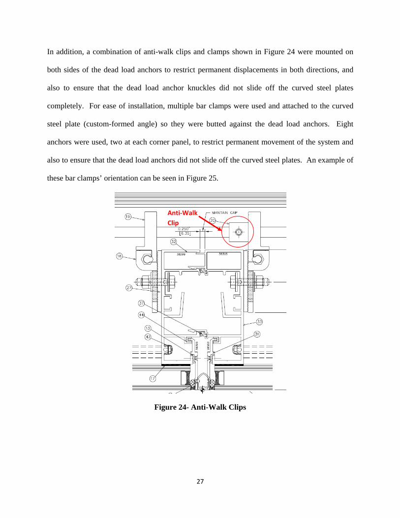
In addition, a combination of anti-walk clips and clamps shown in Figure 24 were mounted on
both sides of the dead load anchors to restrict permanent displacements in both directions, and
also to ensure that the dead load anchor knuckles did not slide off the curved steel plates
completely. For ease of installation, multiple bar clamps were used and attached to the curved
steel plate (custom-formed angle) so they were butted against the dead load anchors. Eight
anchors were used, two at each corner panel, to restrict permanent movement of the system and
also to ensure that the dead load anchors did not slide off the curved steel plates. An example of
these bar clamps’ orientation can be seen in Figure 25.
Figure 24- Anti-Walk Clips
Anti‐Walk Clip
28
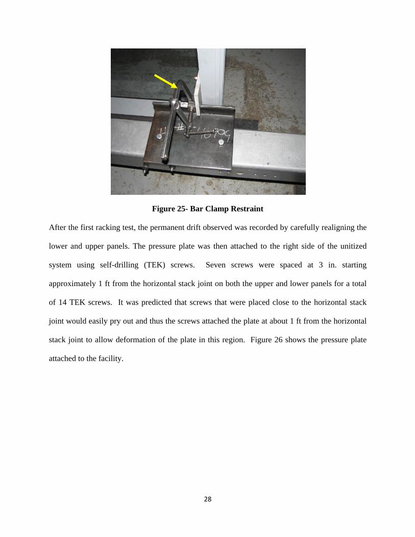
Figure 25- Bar Clamp Restraint
After the first racking test, the permanent drift observed was recorded by carefully realigning the
lower and upper panels. The pressure plate was then attached to the right side of the unitized
system using self-drilling (TEK) screws. Seven screws were spaced at 3 in. starting
approximately 1 ft from the horizontal stack joint on both the upper and lower panels for a total
of 14 TEK screws. It was predicted that screws that were placed close to the horizontal stack
joint would easily pry out and thus the screws attached the plate at about 1 ft from the horizontal
stack joint to allow deformation of the plate in this region. Figure 26 shows the pressure plate
attached to the facility.
29
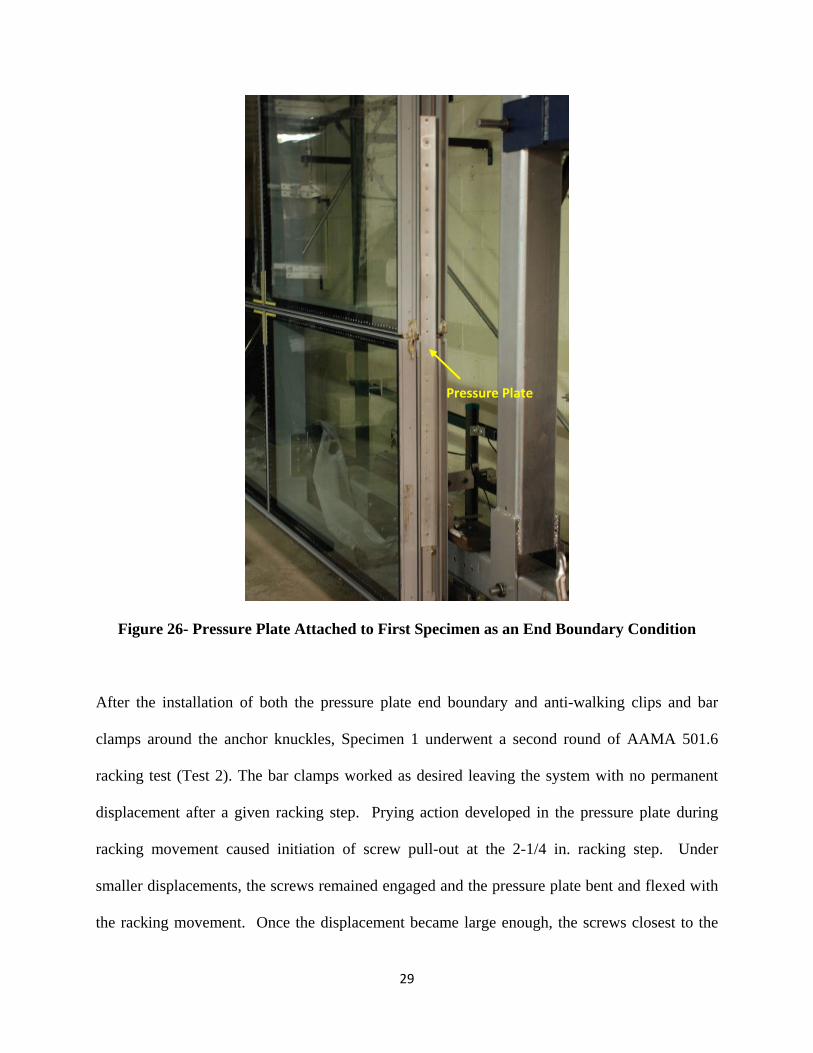
Figure 26- Pressure Plate Attached to First Specimen as an End Boundary Condition
After the installation of both the pressure plate end boundary and anti-walking clips and bar
clamps around the anchor knuckles, Specimen 1 underwent a second round of AAMA 501.6
racking test (Test 2). The bar clamps worked as desired leaving the system with no permanent
displacement after a given racking step. Prying action developed in the pressure plate during
racking movement caused initiation of screw pull-out at the 2-1/4 in. racking step. Under
smaller displacements, the screws remained engaged and the pressure plate bent and flexed with
the racking movement. Once the displacement became large enough, the screws closest to the
Pressure Plate
30
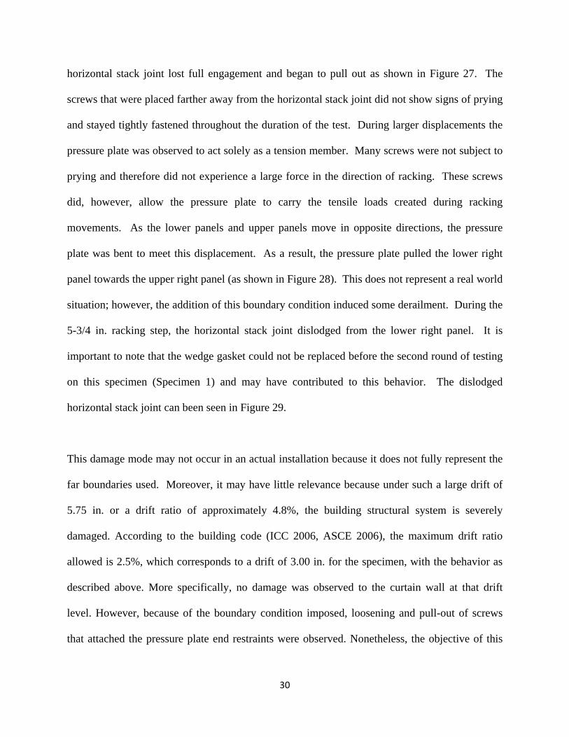
horizontal stack joint lost full engagement and began to pull out as shown in Figure 27. The
screws that were placed farther away from the horizontal stack joint did not show signs of prying
and stayed tightly fastened throughout the duration of the test. During larger displacements the
pressure plate was observed to act solely as a tension member. Many screws were not subject to
prying and therefore did not experience a large force in the direction of racking. These screws
did, however, allow the pressure plate to carry the tensile loads created during racking
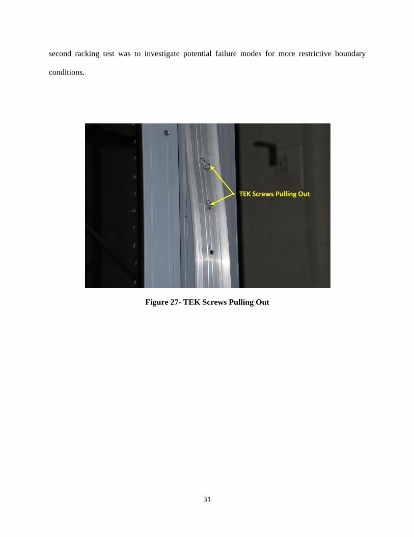
movements. As the lower panels and upper panels move in opposite directions, the pressure
plate was bent to meet this displacement. As a result, the pressure plate pulled the lower right
panel towards the upper right panel (as shown in Figure 28). This does not represent a real world
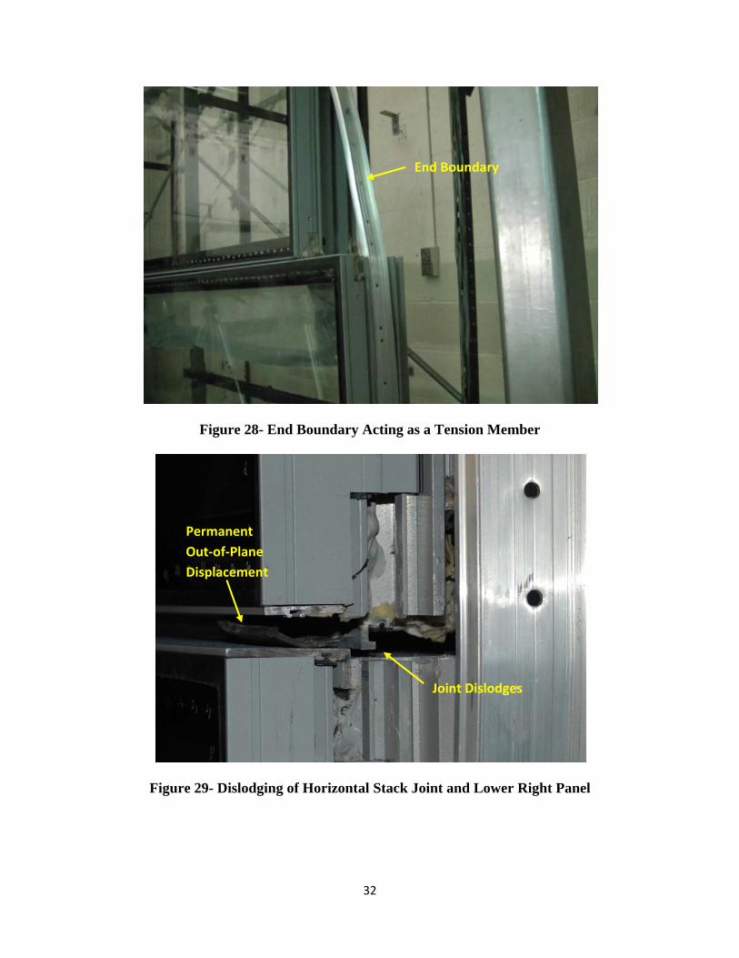
situation; however, the addition of this boundary condition induced some derailment. During the
5-3/4 in. racking step, the horizontal stack joint dislodged from the lower right panel. It is
important to note that the wedge gasket could not be replaced before the second round of testing
on this specimen (Specimen 1) and may have contributed to this behavior. The dislodged
horizontal stack joint can been seen in Figure 29.
This damage mode may not occur in an actual installation because it does not fully represent the
far boundaries used. Moreover, it may have little relevance because under such a large drift of
5.75 in. or a drift ratio of approximately 4.8%, the building structural system is severely
damaged. According to the building code (ICC 2006, ASCE 2006), the maximum drift ratio
allowed is 2.5%, which corresponds to a drift of 3.00 in. for the specimen, with the behavior as
described above. More specifically, no damage was observed to the curtain wall at that drift
level. However, because of the boundary condition imposed, loosening and pull-out of screws
that attached the pressure plate end restraints were observed. Nonetheless, the objective of this
31
second racking test was to investigate potential failure modes for more restrictive boundary
conditions.
Figure 27- TEK Screws Pulling Out
TEK Screws Pulling Out
32
Figure 28- End Boundary Acting as a Tension Member
Figure 29- Dislodging of Horizontal Stack Joint and Lower Right Panel
Joint Dislodges
Permanent Out‐of‐Plane Displacement
End Boundary
33
As a result of the horizontal stack joint dislodging, the right panels were free to move out of
plane as shown in Figure 29. Under such a boundary condition, this can potentially create a
situation where an entire unitized panel or part of it has a greater chance of derailment at the
stack joint. During possible subsequent additional racking, a panel’s dead load anchors may
slide off the curved steel plates (refer to Figure 15) or the racking motion may cause the dead
load anchors (knuckles) to jump over the curved steel plate (custom-formed angles). This failure
mode was not observed during testing, but the experiment shows the importance of sufficient
dead load anchor design and its restraint.
It should be emphasized that the objective of adding the boundary conditions was indeed to
impose a condition on the specimen to identify potential mode of failure if such a boundary
condition is created as a result of building movement during an earthquake. Therefore, what this
experiment showed is that the worst case scenario would be a potential derailment at stack joint.
However, since the upper panel is supported by the bearing supports (curved steel plates (Figure
14), fallout of the panel as a whole is highly unlikely as a result of such derailment for properly
designed and erected bearing supports, which the curtain wall designer would build into their
respective systems.
5.3. Specimen 2, Test 1
A second unitized system (Specimen 2) was constructed in the same manner as the first
specimen. This specimen was also subjected to three full, AAMA 501.6 racking test. The
specimen was unrestrained during the first test (Test 1), and different end boundary conditions
were employed for the second test (Test 2) and the third test (Test 3).
34
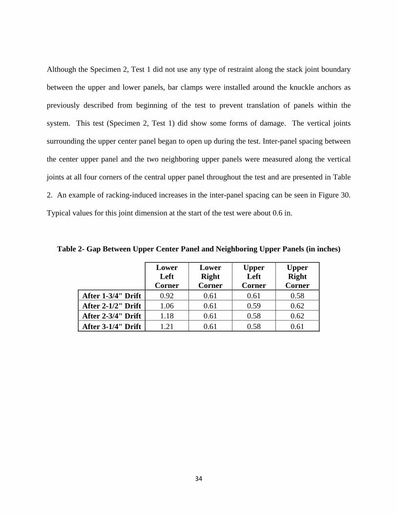
Although the Specimen 2, Test 1 did not use any type of restraint along the stack joint boundary
between the upper and lower panels, bar clamps were installed around the knuckle anchors as
previously described from beginning of the test to prevent translation of panels within the
system. This test (Specimen 2, Test 1) did show some forms of damage. The vertical joints
surrounding the upper center panel began to open up during the test. Inter-panel spacing between
the center upper panel and the two neighboring upper panels were measured along the vertical
joints at all four corners of the central upper panel throughout the test and are presented in Table
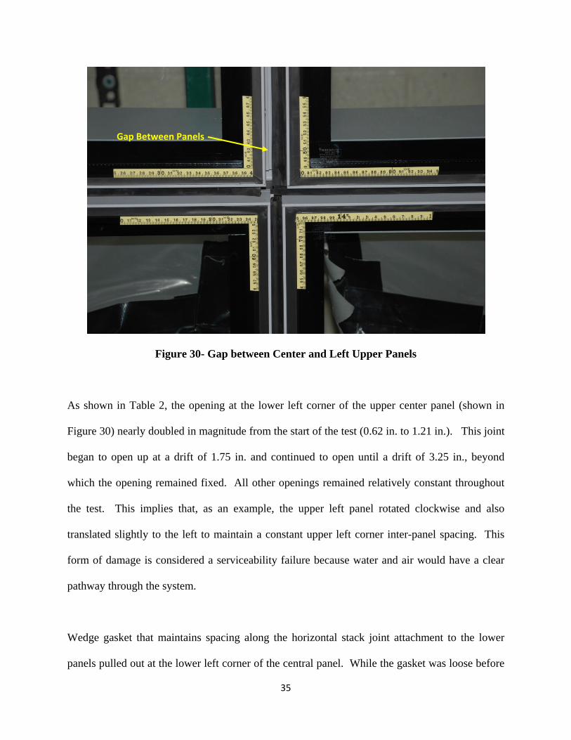
2. An example of racking-induced increases in the inter-panel spacing can be seen in Figure 30.
Typical values for this joint dimension at the start of the test were about 0.6 in.
Table 2- Gap Between Upper Center Panel and Neighboring Upper Panels (in inches)
Lower Left
Corner
Lower Right
Corner
Upper Left
Corner
Upper Right
Corner After 1-3/4" Drift 0.92 0.61 0.61 0.58 After 2-1/2" Drift 1.06 0.61 0.59 0.62 After 2-3/4" Drift 1.18 0.61 0.58 0.62 After 3-1/4" Drift 1.21 0.61 0.58 0.61
35
Figure 30- Gap between Center and Left Upper Panels
As shown in Table 2, the opening at the lower left corner of the upper center panel (shown in
Figure 30) nearly doubled in magnitude from the start of the test (0.62 in. to 1.21 in.). This joint
began to open up at a drift of 1.75 in. and continued to open until a drift of 3.25 in., beyond
which the opening remained fixed. All other openings remained relatively constant throughout
the test. This implies that, as an example, the upper left panel rotated clockwise and also
translated slightly to the left to maintain a constant upper left corner inter-panel spacing. This
form of damage is considered a serviceability failure because water and air would have a clear
pathway through the system.
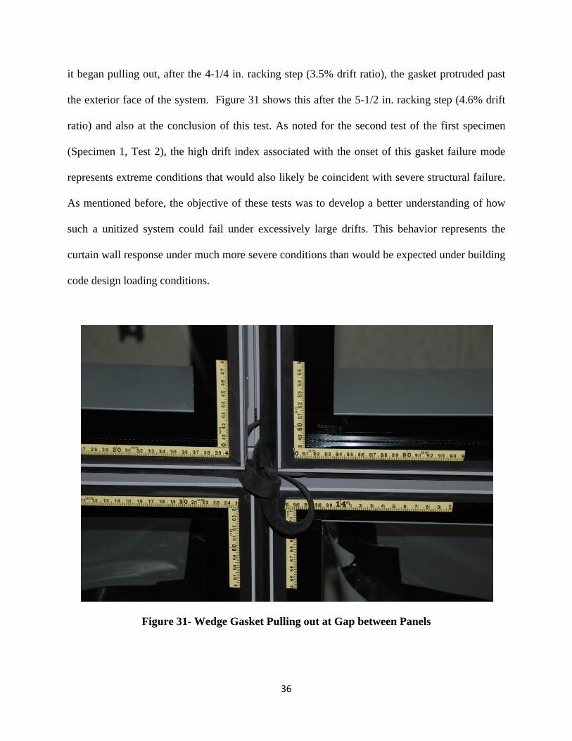
Wedge gasket that maintains spacing along the horizontal stack joint attachment to the lower
panels pulled out at the lower left corner of the central panel. While the gasket was loose before
Gap Between Panels
36
it began pulling out, after the 4-1/4 in. racking step (3.5% drift ratio), the gasket protruded past
the exterior face of the system. Figure 31 shows this after the 5-1/2 in. racking step (4.6% drift
ratio) and also at the conclusion of this test. As noted for the second test of the first specimen
(Specimen 1, Test 2), the high drift index associated with the onset of this gasket failure mode
represents extreme conditions that would also likely be coincident with severe structural failure.
As mentioned before, the objective of these tests was to develop a better understanding of how
such a unitized system could fail under excessively large drifts. This behavior represents the
curtain wall response under much more severe conditions than would be expected under building
code design loading conditions.
Figure 31- Wedge Gasket Pulling out at Gap between Panels
37
5.4 Specimen 2, Test 2
Because no permanent damage to the system was encountered during the first racking test, the
second unitized system specimen was realigned and prepared for a second racking test
(Specimen 2, Test 2). For this test, a new boundary condition was used in an effort to mitigate
the amount of fastener pullout observed in the second test of the first specimen (Specimen1, Test
2) and to prevent the end boundary from acting as a tension member. It was observed that the
fasteners used for the pressure plate boundary condition used in the first specimen test
experienced significant prying. Also, once the fasteners closest to the horizontal stack joint
pulled out, the pressure plate served mainly as a tension member. In an initial effort to create a
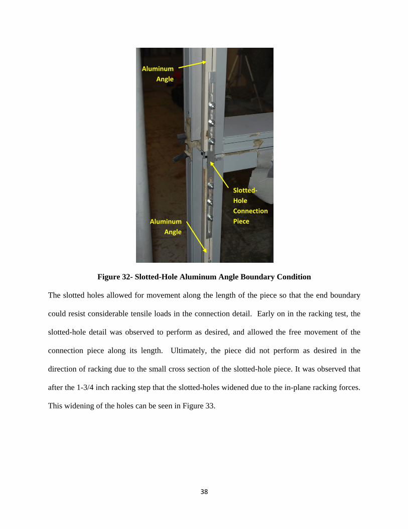
more accurate boundary condition, two readily available aluminum angles and a slotted-hole
aluminum connection piece were used. The aluminum angles were attached to the back side of
the specimen at both ends so that the screws used for fastening were pointed out-of-plane
(perpendicular) with respect to the racking plane. This orientation eliminated the prying action
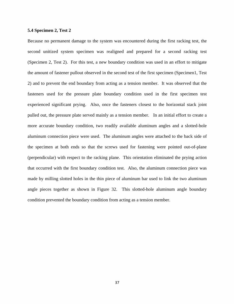
that occurred with the first boundary condition test. Also, the aluminum connection piece was
made by milling slotted holes in the thin piece of aluminum bar used to link the two aluminum
angle pieces together as shown in Figure 32. This slotted-hole aluminum angle boundary
condition prevented the boundary condition from acting as a tension member.
38
Figure 32- Slotted-Hole Aluminum Angle Boundary Condition
The slotted holes allowed for movement along the length of the piece so that the end boundary
could resist considerable tensile loads in the connection detail. Early on in the racking test, the
slotted-hole detail was observed to perform as desired, and allowed the free movement of the
connection piece along its length. Ultimately, the piece did not perform as desired in the
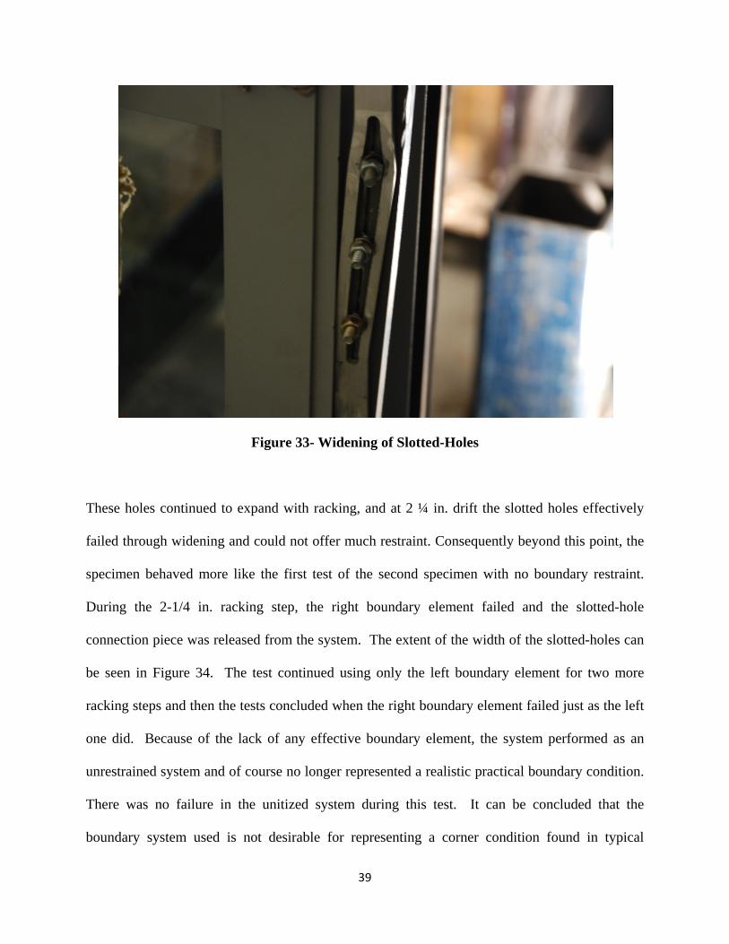
direction of racking due to the small cross section of the slotted-hole piece. It was observed that
after the 1-3/4 inch racking step that the slotted-holes widened due to the in-plane racking forces.
This widening of the holes can be seen in Figure 33.
Aluminum Angle
Aluminum Angle
Slotted‐Hole Connection Piece
39
Figure 33- Widening of Slotted-Holes
These holes continued to expand with racking, and at 2 ¼ in. drift the slotted holes effectively
failed through widening and could not offer much restraint. Consequently beyond this point, the
specimen behaved more like the first test of the second specimen with no boundary restraint.
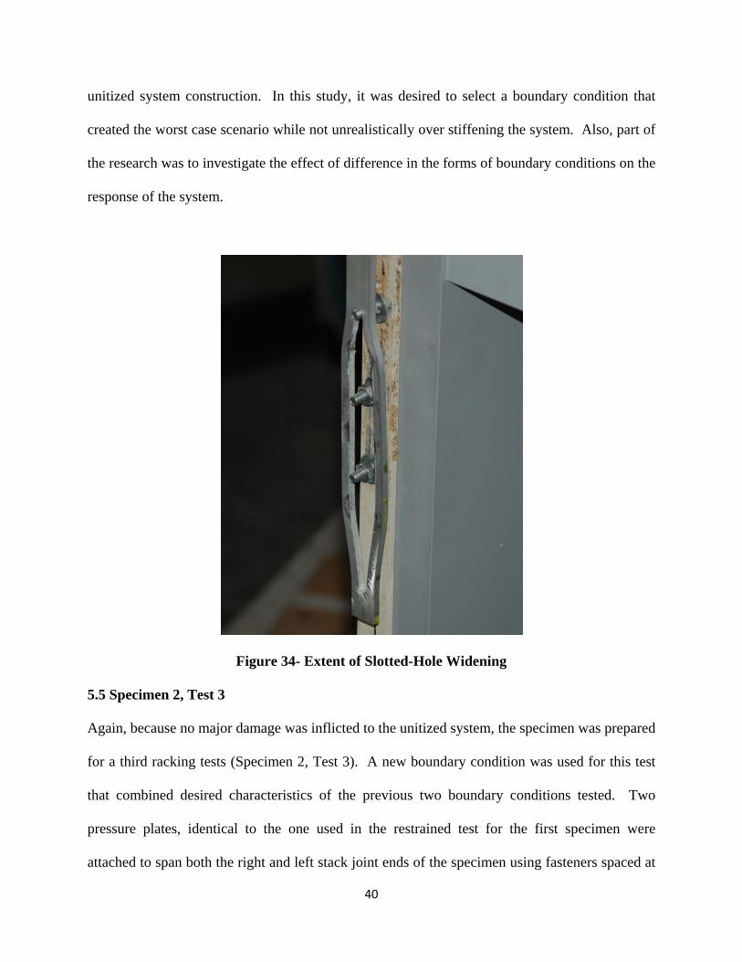
During the 2-1/4 in. racking step, the right boundary element failed and the slotted-hole
connection piece was released from the system. The extent of the width of the slotted-holes can
be seen in Figure 34. The test continued using only the left boundary element for two more
racking steps and then the tests concluded when the right boundary element failed just as the left
one did. Because of the lack of any effective boundary element, the system performed as an
unrestrained system and of course no longer represented a realistic practical boundary condition.
There was no failure in the unitized system during this test. It can be concluded that the
boundary system used is not desirable for representing a corner condition found in typical
40
unitized system construction. In this study, it was desired to select a boundary condition that
created the worst case scenario while not unrealistically over stiffening the system. Also, part of
the research was to investigate the effect of difference in the forms of boundary conditions on the
response of the system.
Figure 34- Extent of Slotted-Hole Widening
5.5 Specimen 2, Test 3
Again, because no major damage was inflicted to the unitized system, the specimen was prepared
for a third racking tests (Specimen 2, Test 3). A new boundary condition was used for this test
that combined desired characteristics of the previous two boundary conditions tested. Two
pressure plates, identical to the one used in the restrained test for the first specimen were
attached to span both the right and left stack joint ends of the specimen using fasteners spaced at
41
6 in. Fastener holes through the pressure plate were also slotted to limit the development of
significant tensile stresses within the boundary element. After application of the 1/2 in. racking
step, it was noticed that the upper left panel separated from the upper center panel, much like in
the second test of the first specimen. This time, the inter-panel spacing was affected along the
entire vertical joint and increased significantly more than during the first specimen throughout
the test. Table 3 shows the gap between the center panel and its neighboring panels after
specific racking steps.
Table 3- Gap Between Upper Center Panel and Neighboring Upper Panels (in inches)
Lower Left
Corner
Lower Right
Corner
Upper Left
Corner
Upper Right
Corner Initial Gaps 0.66 0.58 0.56 0.61
After 1-3/4" Drift 1.08 0.62 0.56 0.61 After 3" Drift 1.38 0.62 0.85 0.62
After 4-3/4" Drift 1.46 0.63 1.16 0.62
The nature of these gaps differs slightly from those of the first specimen. The first specimen
showed a gap only at the lower left corner, while the slotted-hole pressure plate end condition
test showed a large gap at the top and bottom of the left vertical center panel edge. This slotted-
hole pressure plate end boundary experienced a similar failure to that of the first restrained test
(first and second specimens 1 test 2). During the 4-1/4 in. racking step, the horizontal stack joint
dislodged from the lower left panel as shown in Figure 35. The lower left panel was pushed
towards the exterior of the wall system relative to the upper left panel. Again, this represents a
derailment potential noting that only the dead load anchors would be holding the upper left panel
in place.
42
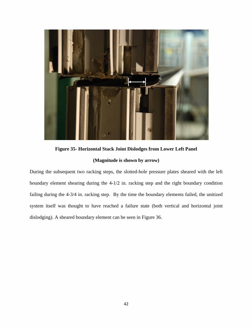
Figure 35- Horizontal Stack Joint Dislodges from Lower Left Panel
(Magnitude is shown by arrow)
During the subsequent two racking steps, the slotted-hole pressure plates sheared with the left
boundary element shearing during the 4-1/2 in. racking step and the right boundary condition
failing during the 4-3/4 in. racking step. By the time the boundary elements failed, the unitized
system itself was thought to have reached a failure state (both vertical and horizontal joint
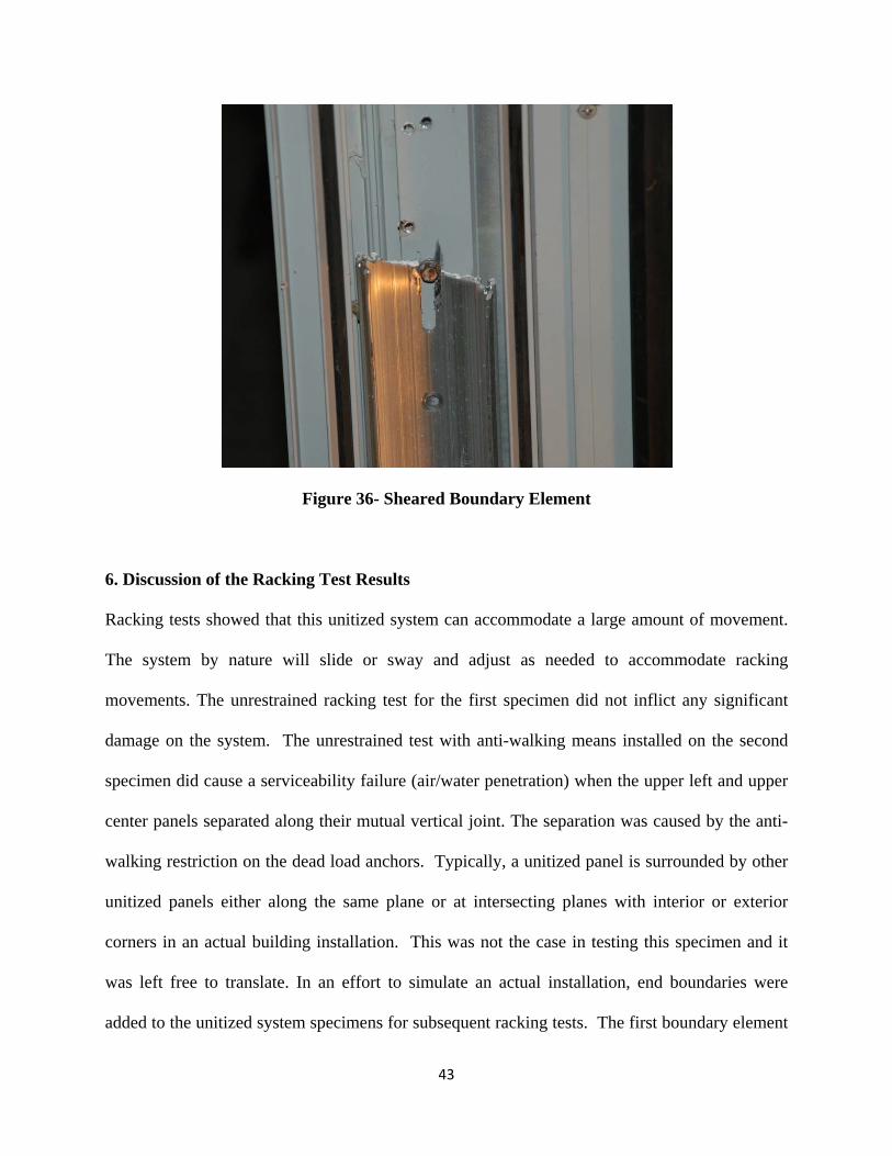
dislodging). A sheared boundary element can be seen in Figure 36.
43
Figure 36- Sheared Boundary Element
6. Discussion of the Racking Test Results
Racking tests showed that this unitized system can accommodate a large amount of movement.
The system by nature will slide or sway and adjust as needed to accommodate racking
movements. The unrestrained racking test for the first specimen did not inflict any significant
damage on the system. The unrestrained test with anti-walking means installed on the second
specimen did cause a serviceability failure (air/water penetration) when the upper left and upper
center panels separated along their mutual vertical joint. The separation was caused by the anti-
walking restriction on the dead load anchors. Typically, a unitized panel is surrounded by other
unitized panels either along the same plane or at intersecting planes with interior or exterior
corners in an actual building installation. This was not the case in testing this specimen and it
was left free to translate. In an effort to simulate an actual installation, end boundaries were
added to the unitized system specimens for subsequent racking tests. The first boundary element
44
used (a pressure plate) was attached to only the right side of the system and did not incorporate
slotted-holes for the fasteners. The pressure plate proved to be flexible enough to allow some
movement, but also created an end condition that did not allow unlimited movement. During
testing with this detail, the unitized system did experience some serviceability damage when the
horizontal stack joint released from the lower panels. The second end boundary installed was a
slotted-hole angle connection. It was noticed during latter racking steps using the pressure plate
end boundary element that the pressure plate acted as a tension member, which led to the use of
slotted-holes. This end boundary, while good in concept, did not perform as desired. The third
boundary element combined the two previously used elements to more accurately portray a real
installation. A pressure plate was used with slotted-holes for fasteners to allow for movement
along the vertical axis. The unitized system specimen tested with the slotted-hole pressure plate
boundary element experienced a similar but more extensive failure exhibited by opening of the
entire vertical joint between the upper left and upper center panels. Based on racking tests, weak
points in the unitized system have been determined. Depending on the boundary conditions in
real life situation, the stack wiper seal and the wedge gasket seals could be vulnerable to pullout
to some degree. The horizontal stack joint is susceptible to dislodging from the lower panels
under certain boundary conditions and very large racking displacements. Vertical inter-panel
joints are also vulnerable to some separation, leaving a pathway for air and water penetration.
The damage behavior reported occurred at drifts much larger than the maximum code allowable
drifts.
45
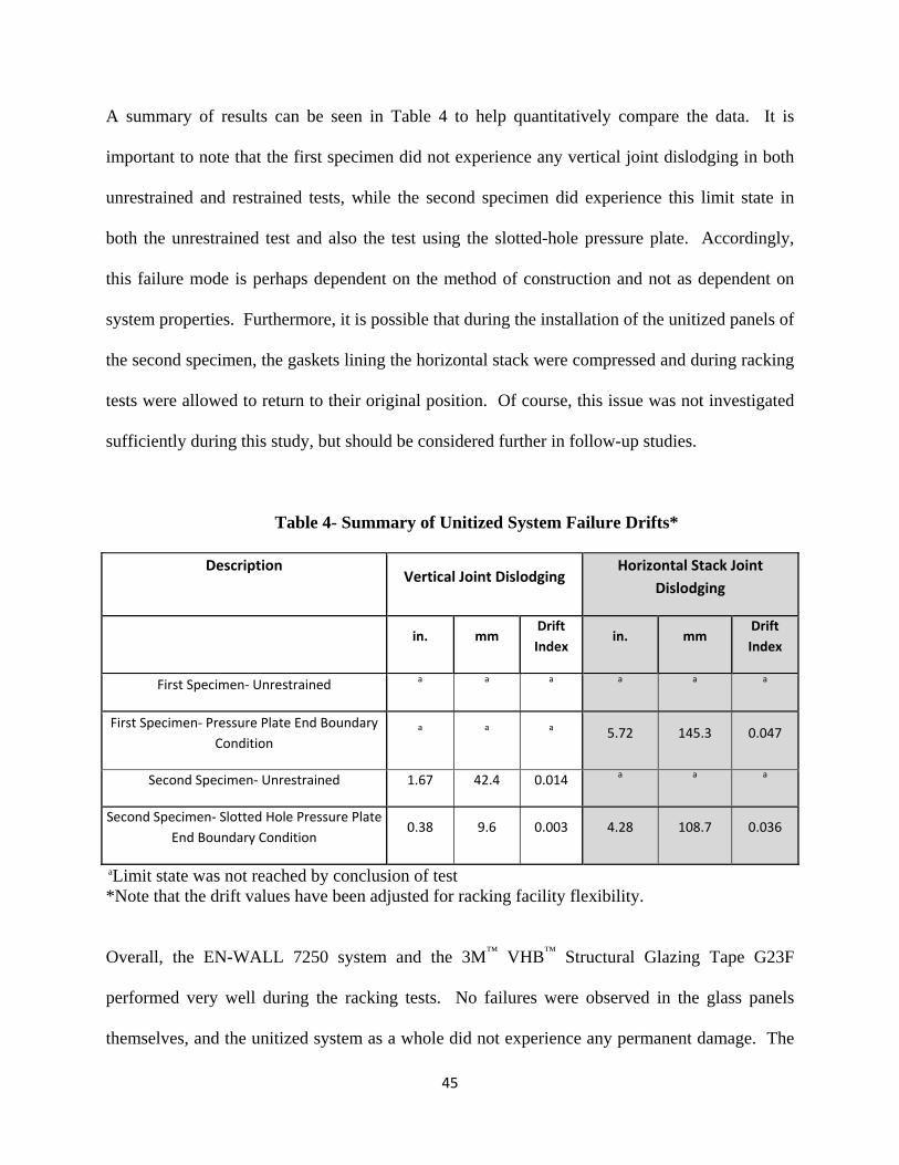
A summary of results can be seen in Table 4 to help quantitatively compare the data. It is
important to note that the first specimen did not experience any vertical joint dislodging in both
unrestrained and restrained tests, while the second specimen did experience this limit state in
both the unrestrained test and also the test using the slotted-hole pressure plate. Accordingly,
this failure mode is perhaps dependent on the method of construction and not as dependent on
system properties. Furthermore, it is possible that during the installation of the unitized panels of
the second specimen, the gaskets lining the horizontal stack were compressed and during racking
tests were allowed to return to their original position. Of course, this issue was not investigated
sufficiently during this study, but should be considered further in follow-up studies.
Table 4- Summary of Unitized System Failure Drifts*
Description Vertical Joint Dislodging
Horizontal Stack Joint Dislodging
in. mm
Drift Index
in. mm Drift Index
First Specimen‐ Unrestrained a a a a a a
First Specimen‐ Pressure Plate End Boundary Condition
a a a 5.72 145.3 0.047
Second Specimen‐ Unrestrained 1.67 42.4 0.014 a a a
Second Specimen‐ Slotted Hole Pressure Plate End Boundary Condition
0.38 9.6 0.003 4.28 108.7 0.036
aLimit state was not reached by conclusion of test *Note that the drift values have been adjusted for racking facility flexibility.
Overall, the EN-WALL 7250 system and the 3M™ VHB™ Structural Glazing Tape G23F
performed very well during the racking tests. No failures were observed in the glass panels
themselves, and the unitized system as a whole did not experience any permanent damage. The
46
horizontal stack joint failure occurred at relatively high drifts, enhancing the system’s seismic
capacity.
7. Air Leakage Tests and Results
Air leakage tests were performed in accordance to the ASTM E 283-04 (ASTM 2004) standard.
This standard calls for a sealed pressurized chamber to attach to the testing specimen making
sure that the seal that binds the chamber and the specimen is air-tight. The chamber is
pressurized to a given pressure. This pressure is targeted to be 75 pascals per ASTM E 283-04,
but certain joints were unable to reach this pressure due to air leakage through the unitized
system and thus a lower pressure was used (either 25 or 50 pascals), The test then measures the
amount of air it takes to maintain the given pressure in the chamber, which is also the amount of
air that is leaking through the specimen. The unitized system was tested along the four joints
that surround the center glass panel. The bottom joint extended the width of the specimen as the
horizontal stack joint was a continuous member and the entire joint needed to be tested. The
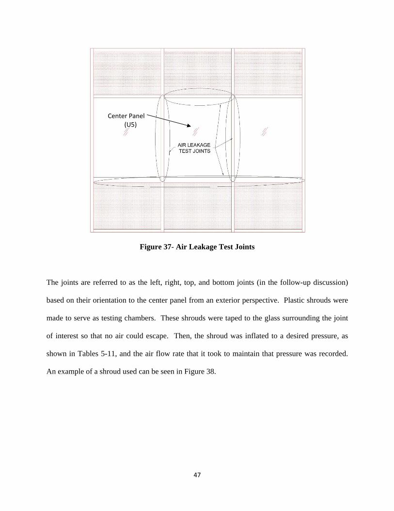
joints tested can be seen in Figure 37.
47
Figure 37- Air Leakage Test Joints
The joints are referred to as the left, right, top, and bottom joints (in the follow-up discussion)
based on their orientation to the center panel from an exterior perspective. Plastic shrouds were
made to serve as testing chambers. These shrouds were taped to the glass surrounding the joint
of interest so that no air could escape. Then, the shroud was inflated to a desired pressure, as
shown in Tables 5-11, and the air flow rate that it took to maintain that pressure was recorded.
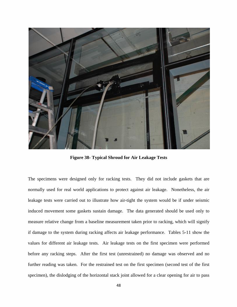
An example of a shroud used can be seen in Figure 38.
Center Panel (U5)
48
Figure 38- Typical Shroud for Air Leakage Tests
The specimens were designed only for racking tests. They did not include gaskets that are
normally used for real world applications to protect against air leakage. Nonetheless, the air
leakage tests were carried out to illustrate how air-tight the system would be if under seismic
induced movement some gaskets sustain damage. The data generated should be used only to
measure relative change from a baseline measurement taken prior to racking, which will signify
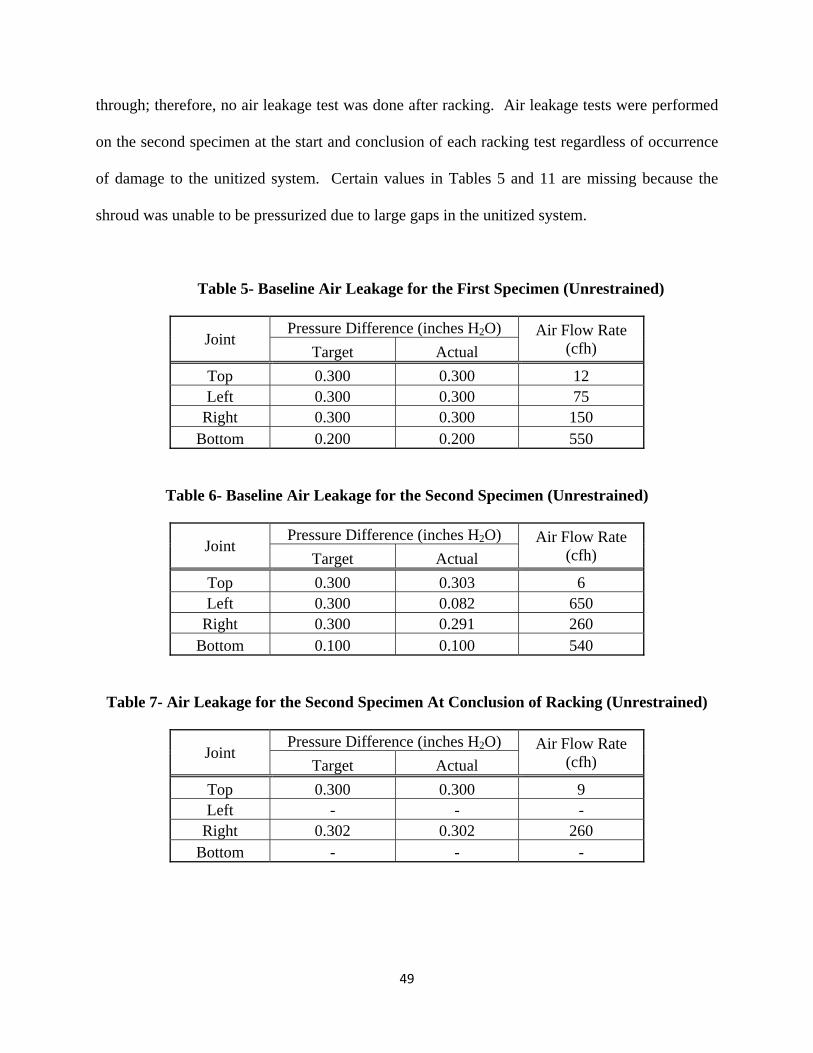
if damage to the system during racking affects air leakage performance. Tables 5-11 show the
values for different air leakage tests. Air leakage tests on the first specimen were performed
before any racking steps. After the first test (unrestrained) no damage was observed and no
further reading was taken. For the restrained test on the first specimen (second test of the first
specimen), the dislodging of the horizontal stack joint allowed for a clear opening for air to pass
49
through; therefore, no air leakage test was done after racking. Air leakage tests were performed
on the second specimen at the start and conclusion of each racking test regardless of occurrence
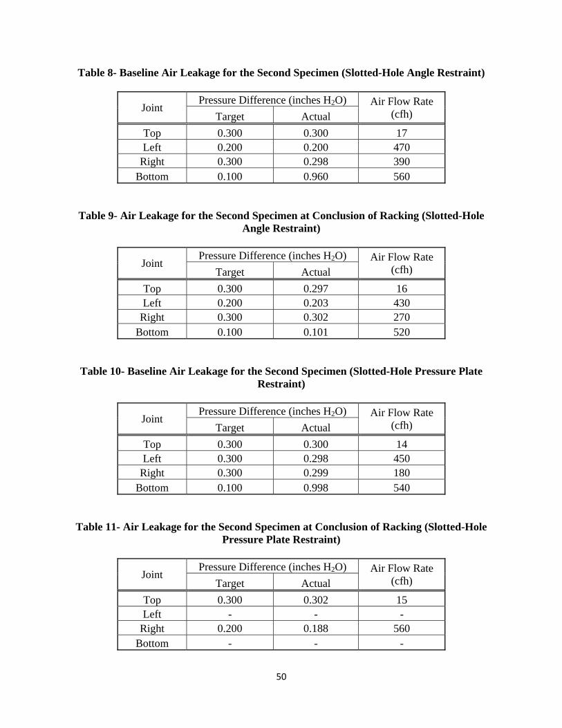
of damage to the unitized system. Certain values in Tables 5 and 11 are missing because the
shroud was unable to be pressurized due to large gaps in the unitized system.
Table 5- Baseline Air Leakage for the First Specimen (Unrestrained)
Joint Pressure Difference (inches H2O) Air Flow Rate
(cfh) Target Actual Top 0.300 0.300 12 Left 0.300 0.300 75
Right 0.300 0.300 150 Bottom 0.200 0.200 550
Table 6- Baseline Air Leakage for the Second Specimen (Unrestrained)
Joint Pressure Difference (inches H2O) Air Flow Rate
(cfh) Target Actual Top 0.300 0.303 6 Left 0.300 0.082 650
Right 0.300 0.291 260 Bottom 0.100 0.100 540
Table 7- Air Leakage for the Second Specimen At Conclusion of Racking (Unrestrained)
Joint Pressure Difference (inches H2O) Air Flow Rate
(cfh) Target Actual Top 0.300 0.300 9 Left - - -
Right 0.302 0.302 260 Bottom - - -
50
Table 8- Baseline Air Leakage for the Second Specimen (Slotted-Hole Angle Restraint)
Joint Pressure Difference (inches H2O) Air Flow Rate
(cfh) Target Actual Top 0.300 0.300 17 Left 0.200 0.200 470
Right 0.300 0.298 390 Bottom 0.100 0.960 560
Table 9- Air Leakage for the Second Specimen at Conclusion of Racking (Slotted-Hole Angle Restraint)
Joint Pressure Difference (inches H2O) Air Flow Rate
(cfh) Target Actual Top 0.300 0.297 16 Left 0.200 0.203 430
Right 0.300 0.302 270 Bottom 0.100 0.101 520
Table 10- Baseline Air Leakage for the Second Specimen (Slotted-Hole Pressure Plate Restraint)
Joint Pressure Difference (inches H2O) Air Flow Rate
(cfh) Target Actual Top 0.300 0.300 14 Left 0.300 0.298 450
Right 0.300 0.299 180 Bottom 0.100 0.998 540
Table 11- Air Leakage for the Second Specimen at Conclusion of Racking (Slotted-Hole Pressure Plate Restraint)
Joint Pressure Difference (inches H2O) Air Flow Rate
(cfh) Target Actual Top 0.300 0.302 15 Left - - -
Right 0.200 0.188 560 Bottom - - -
51
Tables 5-11 show the measured air flow rate needed to achieve a steady state condition for the
pressure difference achieved for each joint. Certain joints were not able to reach the desired
0.300 in. of water pressure and thus needed to be scaled down to an achievable pressure. It is
important to note that the values in Tables 5-11 were not adjusted for temperature and barometric
pressure. To create accurate values, the air flow rate would need to be adjusted for outside
factors. As mentioned before, the purpose of the air flow tests was to compare the air leakage
prior to and after the racking test, and for this reason, the unadjusted values presented in the
tables are sufficient. Air leakage is dependent on the seal created by the gaskets at a given
panel’s joints. The top joint did not vary in air leakage significantly while the left, right, and
bottom joints varied due to the relative translation of the unitized panels.
8. Conclusions
The objective of this testing program was to evaluate the simulated seismic performance of EN-
WALL 7250 unitized curtain wall system test specimens using 3M™ VHB™ Structural Glazing
Tape G23F to form the structural seals. The evaluation was based on cyclic racking tests
following the AAMA 501.6 test protocol. The goal was to identify any failure modes of the
unitized wall system under very high drifts beyond what is expected during design earthquakes.
The full-scale specimens were planar, but testing considered unrestrained planar and restrained
boundary conditions to simulate corner or end boundary conditions. The racking tests of the
planar specimens without any restraint at the stack joint showed no damage to glass, 3M™
VHB™ Structural Glazing Tape G23F or structural sealant weatherseal under the maximum
racking facility drift capacity of 6 in. or a drift ratio of 5.0%, which is larger than what is
expected during a design earthquake or the maximum building code drift ratio of 2.5%.
However, there was some wedge gasket pullout starting when upper panels exhibited permanent
52
displacement at the stack joint at the end of each cycle. Furthermore, there is also the potential
for some vertical joint opening between panels when there are some boundary restraints, and this
poses serviceability issues related to air leakage and moisture. When restraints were introduced
at the stack joint, besides gasket pullout, the test results showed the possibility of vertical joint
opening. At very large drift values (larger than 4.25 in. or 3.5% drift index) some derailment of
the top panels with respect to the bottom panels at the stack joint is also possible. Maximum
design drift index (ratio) for building structural design is 2.5%. Therefore, the drift
corresponding to the potential derailment issue under special boundary restraint conditions is at
least 40% higher than the maximum drift ratio allowed by the building code. Of course, the
restraints introduced are expected to be more severe than in actual installations due to the corner
conditions. The intention was to simulate worst case scenario performance.
Overall, the performance of this curtain wall system under the AAMA 501.6 testing protocol
proved to be satisfactory for a planar system, and this study showed that the stack joint design
can significantly enhance the seismic performance by creating a condition for the adjacent panels
to sway or slide instead of being racked. The full scale unitized curtain wall specimens did not
sustain any glass or 3MTM VHBTM Structural Glazing Tape damage when subjected to the
AAMA 501.6 racking tests. The instrumentation employed for the testing program was not
intended to measure the amount of strains experienced by the glass and 3MTM VHBTM Structural
Glazing Tape (structural sealant) during these tests, and therefore, the resulting stresses were not
determined. Based on the test results and lack of any observed damage to the glass and 3MTM
VHBTM Structural Glazing Tape, however, one can conclude that due to the nature and design of
the unitized curtain wall system, the amount of stress applied to the glass and 3MTM VHBTM
53
Structural Glazing Tape has been small compared to their capacities. In other words, because the
stack joint in effect creates a seismic isolation joint between adjacent vertical panels, the glass-
to-mullion attachment is not expected to experience much in-plane shear during the unrestrained
test cycles. However, the boundary restraint conditions would be expected to create some glass-
to-mullion in-plane shear during the racking tests.
The authors recommend follow-up testing of this curtain wall system by adding a return panel to
the main longitudinal segment in order to test the corner condition and evaluate the response of
the sealants. This would allow the performance of the unitized curtain wall system and the bond
of the structural sealant to be investigated when the wall system is forced to rack as opposed to
the sway condition experienced in the current study.
9. References
3M (2008), 3M TM VHBTM Structural Glazing Tapes -- Technical Guide, Industrial Adhesives
and Tapes Division, St. Paul, MN.
3M (2006), http://multimedia.3m.com/mws/mediawebserver?33333LlQa7xJCOKkEo8pf OKTw
MlHw7lQZMj3wMj3w333333--
AAMA (2009), Recommended Dynamic Test Method for Determining the Seismic Drift Causing
Glass Fallout from a Wall System, Publication No. AAMA 501.6-09, American
Architectural Manufacturers Association (AAMA), Des Plaines, IL.
ASCE (2006), Minimum Design Loads for Buildings and Other Structures, ASCE 7-05,
American Society of Civil Engineers, Reston, VA.
54
ASTM (2004), Standard Test Method for Determining Rate of Air Leakage Through Exterior
Windows, Curtain Wall, and Doors Under Specified Differences Across the Specimen,
ASTM E 283-04, ASTM International, West Conshohocken, PA.
Dow Corning (2006), Structural Silicone Glazing from Dow Corning: Changing the Face of the
World Cities, Dow Corning Corporation, www.dowcorning.com, pp. 1-12.
International Code Council (ICC) (2006), International Building Code (IBC), ICC, Falls Church,
VA.
Memari, A.M., Chen, X., Kremer, P.A., and Behr, R.A. (2006), “Seismic Performance of Two-
Side Structural Silicone Glazing Systems,” Journal of ASTM International, Vol. 3 No. 10,
pp. 1-10.
Memari, A. M., Kremer, P. A., and Behr, R. A., (2010), “Seismic Performance of Four-Side
Structural Sealant Glazing System,” Journal of ASTM International, Accepted for
Publication.
55
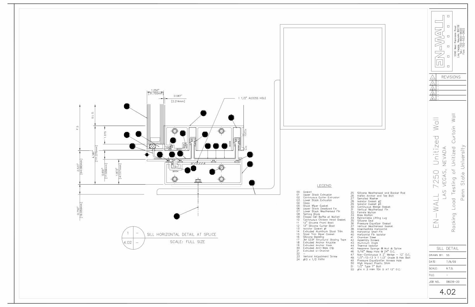
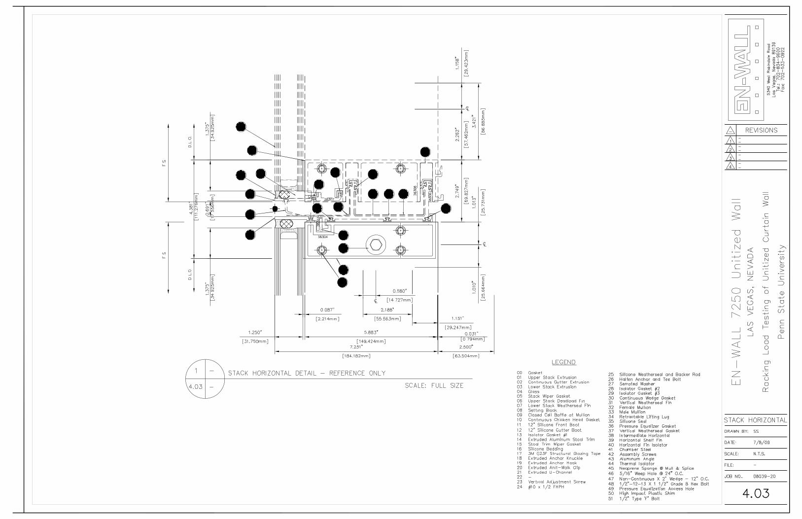
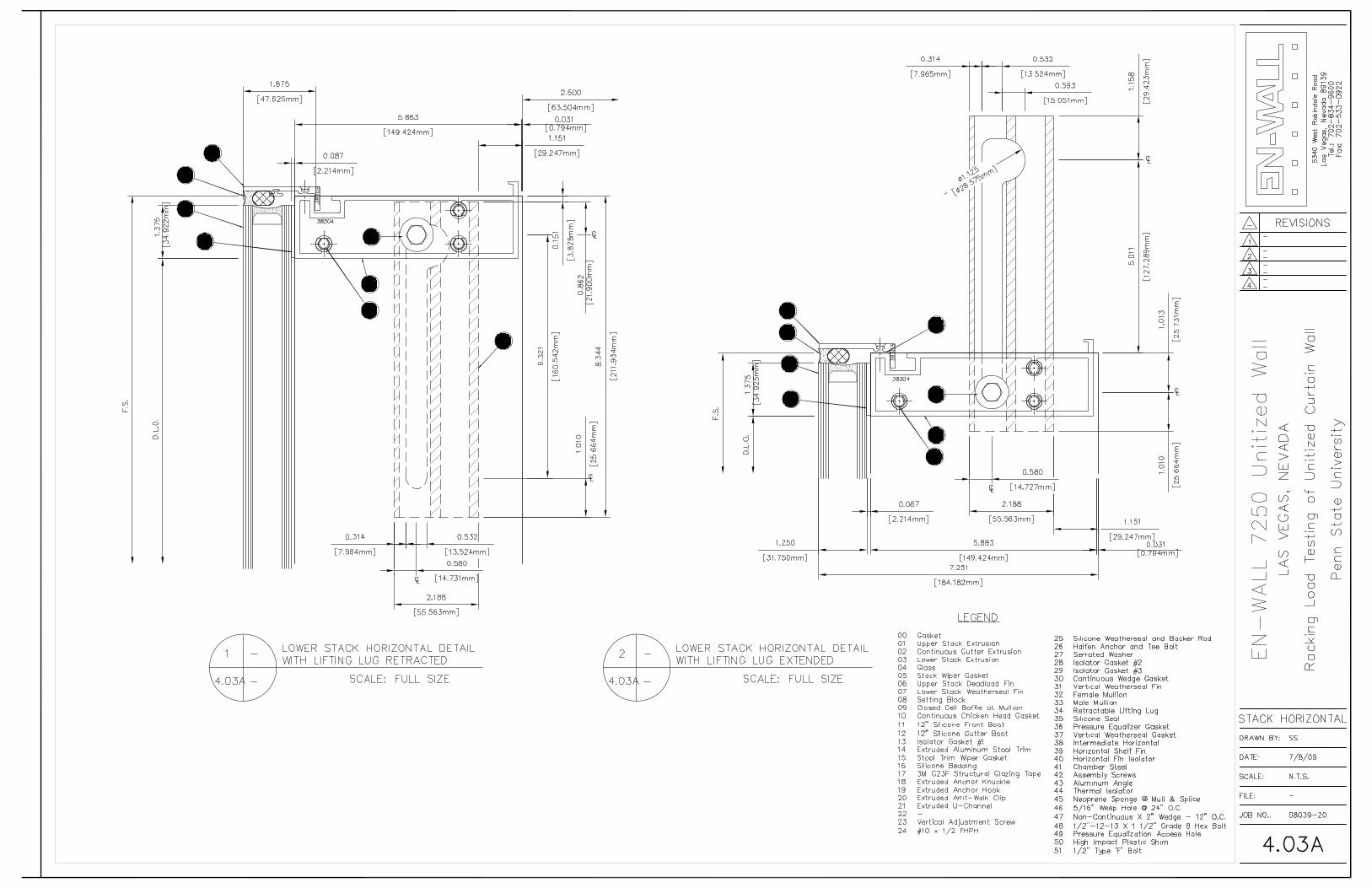
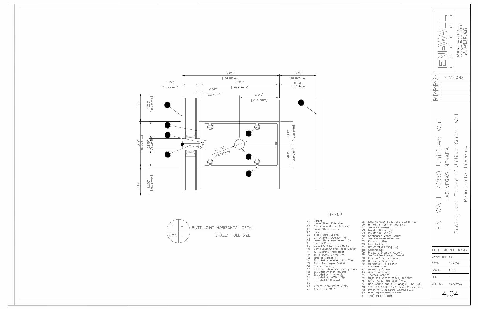
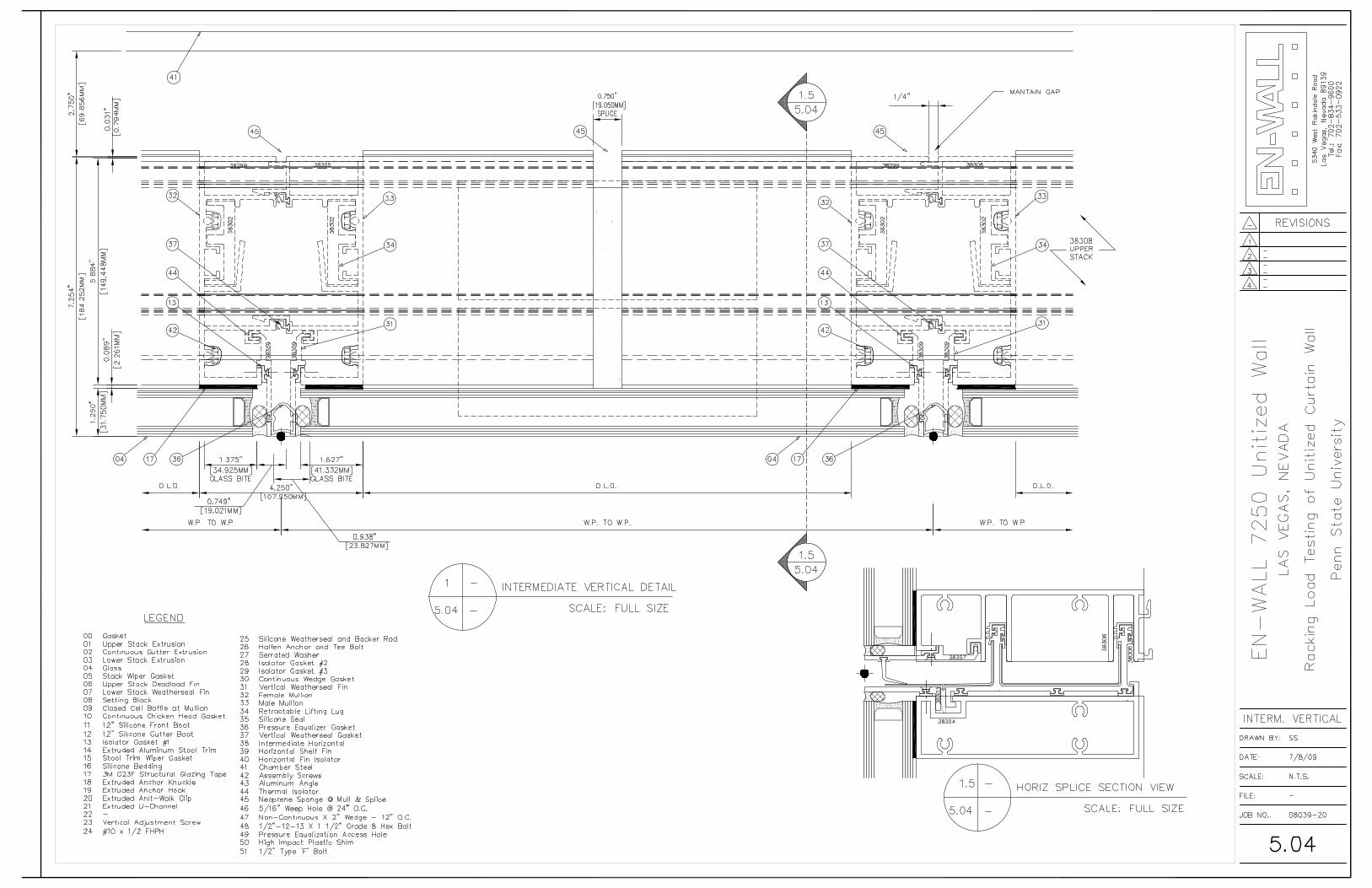
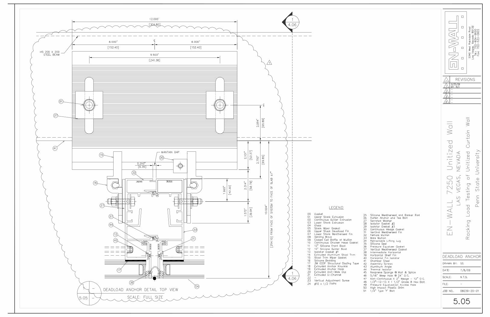
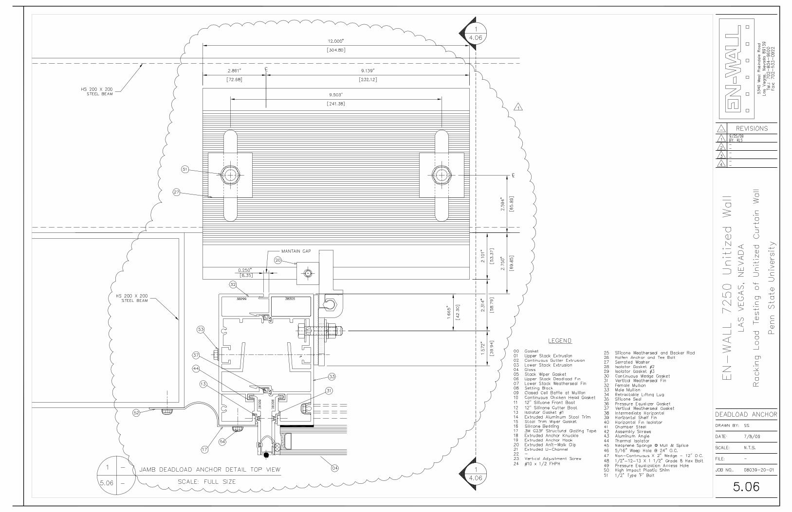
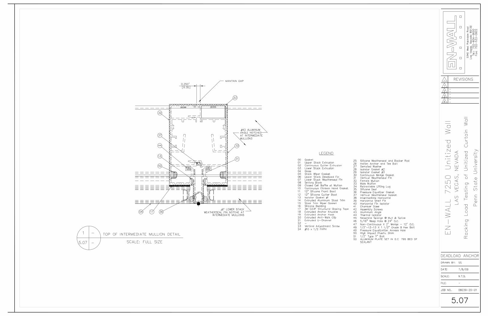
APPENDIX A
Unitized System Details