Embed Size (px)
Citation preview
EPS High-Voltage Generator
PRODUCT SPECIFICATION
RAD-only Configuration
Copyright application © 2014 by EMD Technologies Incorporated. All rights reserved. EMD Technologies Incorporated and the EMD Technologies logo are trademarks of EMD Technologies Incorporated.
Contents of this publication may not be reproduced in any form or by any means, electronic or mechanical, including photocopying and recording, or by any information storage or retrieval system without the written permission of EMD Technologies Incorporated, 400 rue du Parc, Saint-Eustache (Québec), Canada, J7R 0A1.
RAD EPS High-Voltage Generator – Product Specification
Document Number 10000.000.RAD.G1 2/25
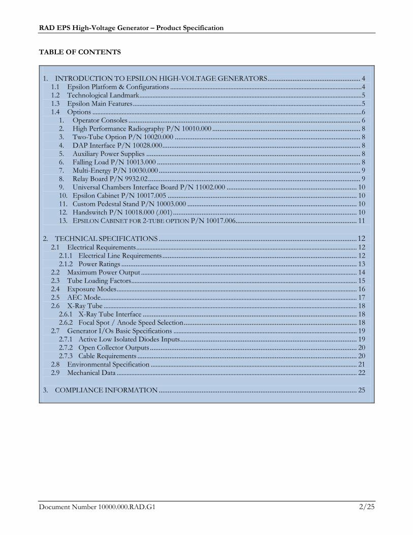
TABLE OF CONTENTS
1. INTRODUCTION TO EPSILON HIGH-VOLTAGE GENERATORS .................................................... 4
1.1 Epsilon Platform & Configurations ...................................................................................................................... 4 1.2 Technological Landmark ......................................................................................................................................... 5 1.3 Epsilon Main Features ............................................................................................................................................. 5 1.4 Options ...................................................................................................................................................................... 6
1. Operator Consoles .................................................................................................................................. 6 2. High Performance Radiography P/N 10010.000 ................................................................................... 8 3. Two-Tube Option P/N 10020.000 ........................................................................................................ 8 4. DAP Interface P/N 10028.000 ............................................................................................................... 8 5. Auxiliary Power Supplies ........................................................................................................................ 8 6. Falling Load P/N 10013.000 .................................................................................................................. 8 7. Multi-Energy P/N 10030.000 ................................................................................................................. 9 8. Relay Board P/N 9932.02 ....................................................................................................................... 9 9. Universal Chambers Interface Board P/N 11002.000 ......................................................................... 10 10. Epsilon Cabinet P/N 10017.005 .......................................................................................................... 10 11. Custom Pedestal Stand P/N 10003.000 ............................................................................................... 10 12. Handswitch P/N 10018.000 (.001) ....................................................................................................... 10 13. EPSILON CABINET FOR 2-TUBE OPTION P/N 10017.006.................................................................... 11
2. TECHNICAL SPECIFICATIONS ............................................................................................................... 12
2.1 Electrical Requirements ........................................................................................................................................ 12 2.1.1 Electrical Line Requirements ............................................................................................................. 12 2.1.2 Power Ratings .................................................................................................................................... 13
2.2 Maximum Power Output ..................................................................................................................................... 14 2.3 Tube Loading Factors ........................................................................................................................................... 15 2.4 Exposure Modes .................................................................................................................................................... 16 2.5 AEC Mode.............................................................................................................................................................. 17 2.6 X-Ray Tube ............................................................................................................................................................ 18
2.6.1 X-Ray Tube Interface ........................................................................................................................ 18 2.6.2 Focal Spot / Anode Speed Selection ................................................................................................. 18
2.7 Generator I/Os Basic Specifications ................................................................................................................. 19 2.7.1 Active Low Isolated Diodes Inputs ................................................................................................... 19 2.7.2 Open Collector Outputs .................................................................................................................... 20 2.7.3 Cable Requirements ........................................................................................................................... 20
2.8 Environmental Specification ............................................................................................................................... 21 2.9 Mechanical Data .................................................................................................................................................... 22
3. COMPLIANCE INFORMATION ............................................................................................................... 25
RAD EPS High-Voltage Generator – Product Specification
Document Number 10000.000.RAD.G1 3/25
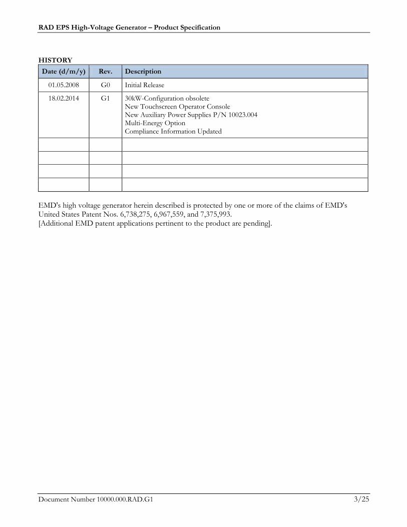
HISTORY
Date (d/m/y) Rev. Description
01.05.2008 G0 Initial Release
18.02.2014 G1 30kW-Configuration obsolete New Touchscreen Operator Console New Auxiliary Power Supplies P/N 10023.004 Multi-Energy Option Compliance Information Updated
EMD's high voltage generator herein described is protected by one or more of the claims of EMD's United States Patent Nos. 6,738,275, 6,967,559, and 7,375,993. [Additional EMD patent applications pertinent to the product are pending].
RAD EPS High-Voltage Generator – Product Specification
Document Number 10000.000.RAD.G1 4/25
1. INTRODUCTION TO EPSILON HIGH-VOLTAGE GENERATORS
1.1 Epsilon Platform & Configurations The EpsilonTM High-Voltage generator is an Advanced High Frequency X-ray Generator designed with a unique power inverter technology and modular conception. As more power or specific features are needed, they simply are added using plug-in modules quickly inserted to the generator's main core. The latter consists of an electronic controller driving an encapsulated high-voltage unit, oil-free. The different configurations are best suited to conventional RAD and to the latest digital procedures. Features and options are summed up in Table 1 and described later in the text.
Table -1. Main Configurations of EPS 45-80 High-Voltage Generator
Conf. (1/2)
kW Operator Console
HPR 2-T C FL Multi-Energy
Pd RT Step
EPS 45 45 O Hs -- O O O O O O
EPS 50 50 O Hs -- O O O O O O
EPS 55 55 O Hs -- O O O O O O
EPS 65 65 O Hs -- O O O O O O
EPS 70 70 O Hs -- O O O O O O
EPS 80 80 O Hs O O O O O O O
HPR : High Performance Radiography 2-T : 2-Tube Option Pd : Pedestal stand
Hs : Handswitch C : Cabinet Rt : Real Time
Conf. (2/2)
All EPS
Anode Starter
A.P.S. Relay AEC Interface
DAPInterf. Ion
(1) S.S. Ion PhD PMT
Low/Dual O O Yes O O O O
A.P.S. : Auxiliary Power Supplies
(24 VDC; 24 VDC/24VAC or 24VAC)
Relay : Relay board (8 progr. relays)
Ion : Ion chamber PhD : Photodiode PMT : Photomultiplier tube
S.S. Ion : Solid State Ion Chambers
SPD : Source to Patient Dose Compensation
DAP : Dose Area Product
Notes: O = Option ; _ _ = Not available. (1) Two ion chambers are supported on all Epsilon generators.
RAD EPS High-Voltage Generator – Product Specification
Document Number 10000.000.RAD.G1 5/25
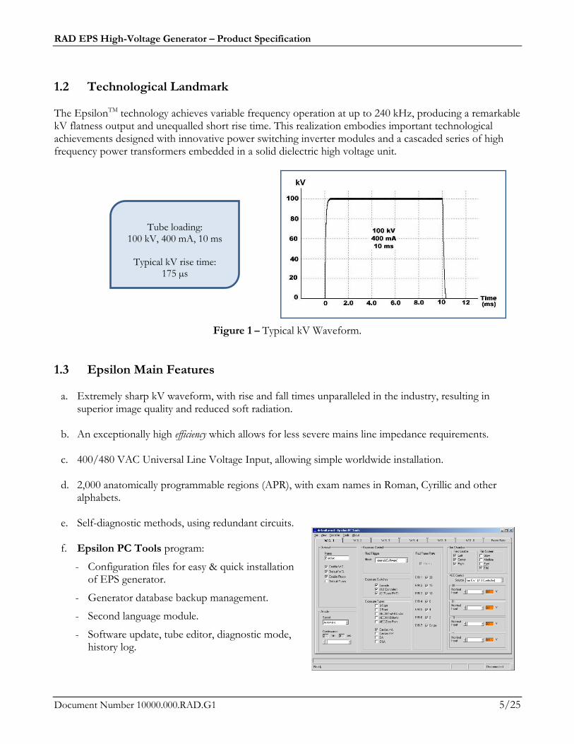
1.2 Technological Landmark The EpsilonTM technology achieves variable frequency operation at up to 240 kHz, producing a remarkable kV flatness output and unequalled short rise time. This realization embodies important technological achievements designed with innovative power switching inverter modules and a cascaded series of high frequency power transformers embedded in a solid dielectric high voltage unit.
Figure 1 – Typical kV Waveform.
1.3 Epsilon Main Features
a. Extremely sharp kV waveform, with rise and fall times unparalleled in the industry, resulting in superior image quality and reduced soft radiation.
b. An exceptionally high efficiency which allows for less severe mains line impedance requirements.
c. 400/480 VAC Universal Line Voltage Input, allowing simple worldwide installation.
d. 2,000 anatomically programmable regions (APR), with exam names in Roman, Cyrillic and other
alphabets.
e. Self-diagnostic methods, using redundant circuits.
f. Epsilon PC Tools program:
- Configuration files for easy & quick installation of EPS generator.
- Generator database backup management.
- Second language module.
- Software update, tube editor, diagnostic mode, history log.
Tube loading:
100 kV, 400 mA, 10 ms
Typical kV rise time: 175 µs
RAD EPS High-Voltage Generator – Product Specification
Document Number 10000.000.RAD.G1 6/25
g. PC serial connectivity providing full flexibility for customer control.
h. Automatic X-ray tube calibration module with X-ray tube emission curves viewer and tube calibration file for backup and export.
1.4 Options 1. Operator Consoles
A. Epsilon Operator Console P/N 9777.51
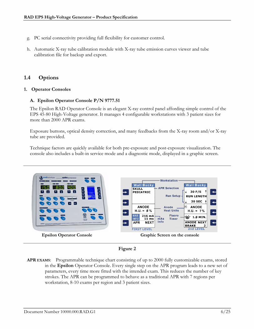
The Epsilon RAD Operator Console is an elegant X-ray control panel affording simple control of the EPS 45-80 High-Voltage generator. It manages 4 configurable workstations with 3 patient sizes for more than 2000 APR exams. Exposure buttons, optical density correction, and many feedbacks from the X-ray room and/or X-ray tube are provided. Technique factors are quickly available for both pre-exposure and post-exposure visualization. The console also includes a built-in service mode and a diagnostic mode, displayed in a graphic screen.
Epsilon Operator Console Graphic Screen on the console
Figure 2
APR EXAMS: Programmable technique chart consisting of up to 2000 fully customizable exams, stored in the Epsilon Operator Console. Every single step on the APR program leads to a new set of parameters, every time more fitted with the intended exam. This reduces the number of key strokes. The APR can be programmed to behave as a traditional APR with 7 regions per workstation, 8-10 exams per region and 3 patient sizes.
RAD EPS High-Voltage Generator – Product Specification
Document Number 10000.000.RAD.G1 7/25
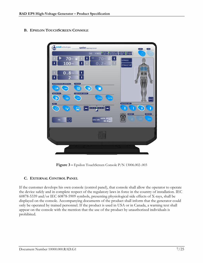
B. EPSILON TOUCHSCREEN CONSOLE
Figure 3 – Epsilon TouchScreen Console P/N 13006.002-.003
C. EXTERNAL CONTROL PANEL If the customer develops his own console (control panel), that console shall allow the operator to operate the device safely and in complete respect of the regulatory laws in force in the country of installation. IEC 60878-5339 and/or IEC 60878-5909 symbols, presenting physiological side effects of X-rays, shall be displayed on the console. Accompanying documents of the product shall inform that the generator could only be operated by trained personnel. If the product is used in USA or in Canada, a warning text shall appear on the console with the mention that the use of the product by unauthorized individuals is prohibited.
RAD EPS High-Voltage Generator – Product Specification
Document Number 10000.000.RAD.G1 8/25
2. High Performance Radiography P/N 10010.000
High Performance Radiography option extends the irradiation time from 10 seconds to 63 seconds and the current by time product from 1000 mAs to 12,500 mAs.
Available on EPS 80 configuration only. 3. Two-Tube Option P/N 10020.000
The 2-Tube option provides a standalone X-ray tube switch and the necessary hardware & software to drive two different X-ray tubes from a single generator. Each tube is assigned to one or more of the four possible workstations. Commutation time to switch tube is about 5 seconds.
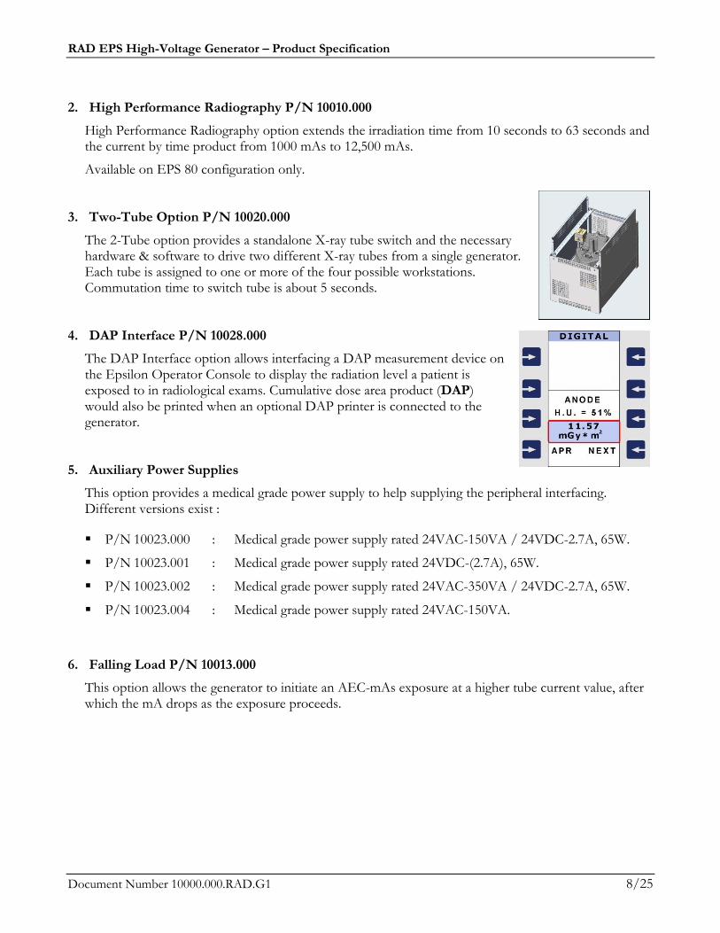
4. DAP Interface P/N 10028.000
The DAP Interface option allows interfacing a DAP measurement device on the Epsilon Operator Console to display the radiation level a patient is exposed to in radiological exams. Cumulative dose area product (DAP) would also be printed when an optional DAP printer is connected to the generator.
5. Auxiliary Power Supplies
This option provides a medical grade power supply to help supplying the peripheral interfacing. Different versions exist :
P/N 10023.000 : Medical grade power supply rated 24VAC-150VA / 24VDC-2.7A, 65W.
P/N 10023.001 : Medical grade power supply rated 24VDC-(2.7A), 65W.
P/N 10023.002 : Medical grade power supply rated 24VAC-350VA / 24VDC-2.7A, 65W.
P/N 10023.004 : Medical grade power supply rated 24VAC-150VA.
6. Falling Load P/N 10013.000
This option allows the generator to initiate an AEC-mAs exposure at a higher tube current value, after which the mA drops as the exposure proceeds.

RAD EPS High-Voltage Generator – Product Specification
Document Number 10000.000.RAD.G1 9/25
7. Multi-Energy P/N 10030.000
This option allows an external controller to vary the kV and/or mA during an exposure or between exposures of a run. The external controller must communicate with the generator through the use of a serial protocol (CANBUS or RS-232) proprietary to EMD Technologies.
Stepping Multi-Energy: Exposure parameters are pre-determined before beginning the run. The procedure can be applied to perform energy subtraction, or to follow a roadmap. All step changes are controlled by CON2 serial protocol.
Real-Time Multi-Energy: Exposure parameters vary live during the run. The procedure can be used for image stitching or for energy subtraction. The multi-energy can be synchronized or not (Figure 4) with the beginning of an exposure during the run.
Legend : ___ ___ ___
= X-ray On
= kV
= mA
Figure 4 – Typical Multi-Energy Exposure (Asynchronous Example) 8. Relay Board P/N 9932.02 This board provides eight programmable relays that can be used to control X-ray room lines as a function of the generator status.
(a) (b)
SPDT Relays ratings:
10 A @ up to 250 VAC;
10 A @ up to 30 VDC.
(a) Relay board mounted on its Assembly Plate;
(b) 12-Position Terminal Block
(28-12 AWG).
Figure 5 – Relay board
RAD EPS High-Voltage Generator – Product Specification
Document Number 10000.000.RAD.G1 10/25
9. Universal Chambers Interface Board P/N 11002.000
Consists of a plug-in board and the necessary software to perform AEC exposures on up to three (3) solid state AEC chambers. This board includes also an additional interface for a standard ion chamber.
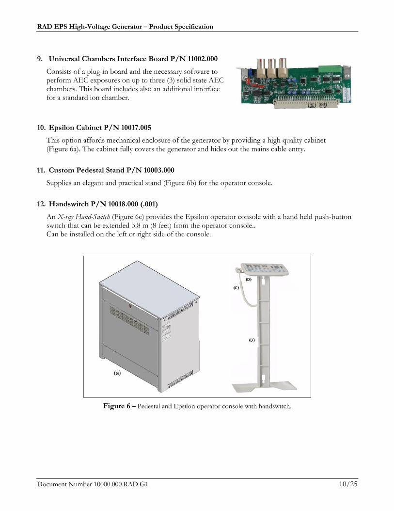
10. Epsilon Cabinet P/N 10017.005
This option affords mechanical enclosure of the generator by providing a high quality cabinet (Figure 6a). The cabinet fully covers the generator and hides out the mains cable entry.
11. Custom Pedestal Stand P/N 10003.000
Supplies an elegant and practical stand (Figure 6b) for the operator console.
12. Handswitch P/N 10018.000 (.001)
An X-ray Hand-Switch (Figure 6c) provides the Epsilon operator console with a hand held push-button switch that can be extended 3.8 m (8 feet) from the operator console.. Can be installed on the left or right side of the console.
Figure 6 – Pedestal and Epsilon operator console with handswitch.
(a)
RAD EPS High-Voltage Generator – Product Specification
Document Number 10000.000.RAD.G1 11/25
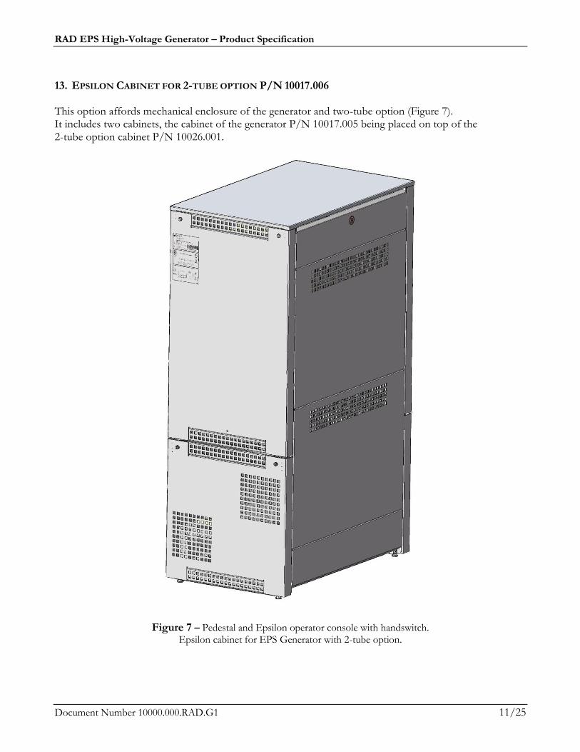
13. EPSILON CABINET FOR 2-TUBE OPTION P/N 10017.006 This option affords mechanical enclosure of the generator and two-tube option (Figure 7). It includes two cabinets, the cabinet of the generator P/N 10017.005 being placed on top of the 2-tube option cabinet P/N 10026.001.
Figure 7 – Pedestal and Epsilon operator console with handswitch. Epsilon cabinet for EPS Generator with 2-tube option.
RAD EPS High-Voltage Generator – Product Specification
Document Number 10000.000.RAD.G1 12/25
2. TECHNICAL SPECIFICATIONS
2.1 Electrical Requirements
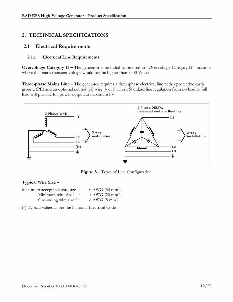
2.1.1 Electrical Line Requirements Overvoltage Category II – The generator is intended to be used in “Overvoltage Category II” locations where the mains transient voltage would not be higher than 2500 Vpeak.
Three-phase Mains Line – The generator requires a three-phase electrical line with a protective earth ground (PE) and an optional neutral (N) wire (4 or 5 wires). Standard line regulation from no load to full load will provide full power output, at maximum kV.
Figure 8 – Types of Line Configuration. Typical Wire Size –
Maximum acceptable wire size : 0 AWG (50 mm2) Minimum wire size (*) : 4 AWG (20 mm2) Grounding wire size (*) : 8 AWG (8 mm2)
(*) Typical values as per the National Electrical Code.
RAD EPS High-Voltage Generator – Product Specification
Document Number 10000.000.RAD.G1 13/25
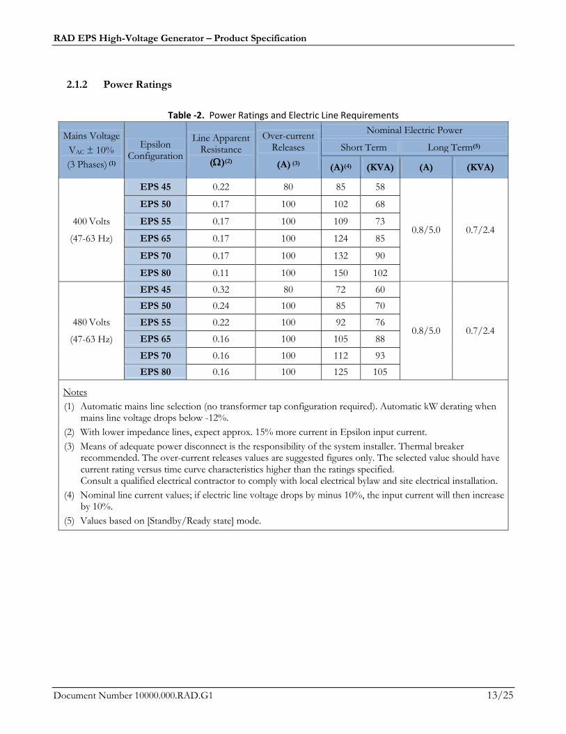
2.1.2 Power Ratings
Table -2. Power Ratings and Electric Line Requirements
Mains Voltage
VAC ± 10%
(3 Phases) (1)
Epsilon Configuration
Line Apparent Resistance
()(2)
Over-current Releases
(A) (3)
Nominal Electric Power
Short Term Long Term(5)
(A)(4) (KVA) (A) (KVA)
400 Volts
(47-63 Hz)
EPS 45 0.22 80 85 58
0.8/5.0 0.7/2.4
EPS 50 0.17 100 102 68
EPS 55 0.17 100 109 73
EPS 65 0.17 100 124 85
EPS 70 0.17 100 132 90
EPS 80 0.11 100 150 102
480 Volts
(47-63 Hz)
EPS 45 0.32 80 72 60
0.8/5.0 0.7/2.4
EPS 50 0.24 100 85 70
EPS 55 0.22 100 92 76
EPS 65 0.16 100 105 88
EPS 70 0.16 100 112 93
EPS 80 0.16 100 125 105
Notes
(1) Automatic mains line selection (no transformer tap configuration required). Automatic kW derating when mains line voltage drops below -12%.
(2) With lower impedance lines, expect approx. 15% more current in Epsilon input current.
(3) Means of adequate power disconnect is the responsibility of the system installer. Thermal breaker recommended. The over-current releases values are suggested figures only. The selected value should have current rating versus time curve characteristics higher than the ratings specified. Consult a qualified electrical contractor to comply with local electrical bylaw and site electrical installation.
(4) Nominal line current values; if electric line voltage drops by minus 10%, the input current will then increase by 10%.
(5) Values based on [Standby/Ready state] mode.
RAD EPS High-Voltage Generator – Product Specification
Document Number 10000.000.RAD.G1 14/25
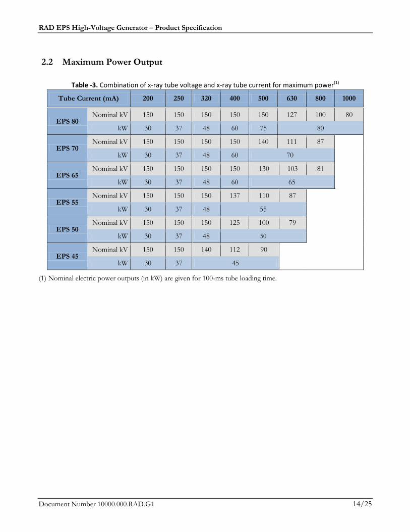
2.2 Maximum Power Output
Table -3. Combination of x-ray tube voltage and x-ray tube current for maximum power(1)
Tube Current (mA) 200 250 320 400 500 630 800 1000
EPS 80 Nominal kV 150 150 150 150 150 127 100 80
kW 30 37 48 60 75 80
EPS 70 Nominal kV 150 150 150 150 140 111 87
kW 30 37 48 60 70
EPS 65 Nominal kV 150 150 150 150 130 103 81
kW 30 37 48 60 65
EPS 55 Nominal kV 150 150 150 137 110 87
kW 30 37 48 55
EPS 50 Nominal kV 150 150 150 125 100 79
kW 30 37 48 50
EPS 45 Nominal kV 150 150 140 112 90
kW 30 37 45
(1) Nominal electric power outputs (in kW) are given for 100-ms tube loading time.
RAD EPS High-Voltage Generator – Product Specification
Document Number 10000.000.RAD.G1 15/25
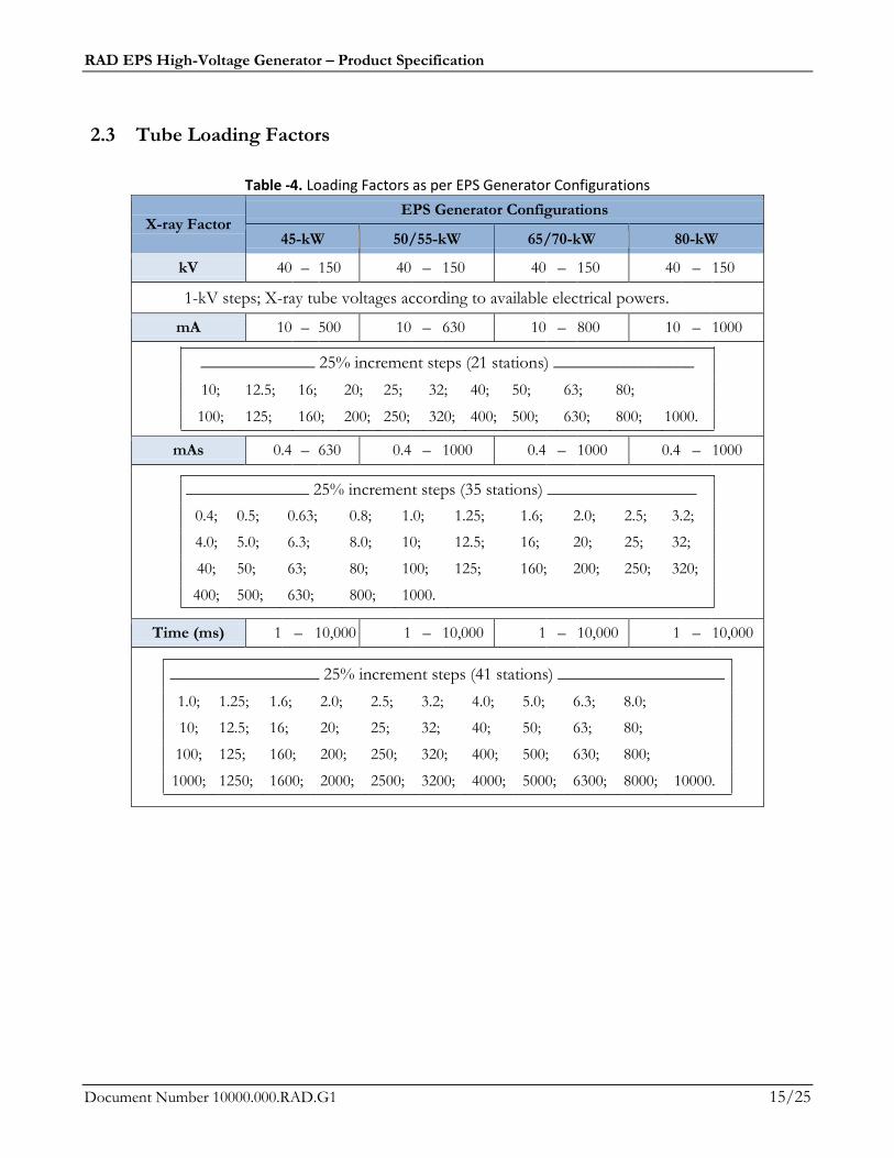
2.3 Tube Loading Factors
Table -4. Loading Factors as per EPS Generator Configurations
X-ray Factor EPS Generator Configurations
45-kW 50/55-kW 65/70-kW 80-kW
kV 40 – 150 40 – 150 40 – 150 40 – 150
1-kV steps; X-ray tube voltages according to available electrical powers.
mA 10 – 500 10 – 630 10 – 800 10 – 1000
_____________ 25% increment steps (21 stations) ________________
10; 12.5; 16; 20; 25; 32; 40; 50; 63; 80;
100; 125; 160; 200; 250; 320; 400; 500; 630; 800; 1000.
mAs 0.4 – 630 0.4 – 1000 0.4 – 1000 0.4 – 1000
______________ 25% increment steps (35 stations) _________________
0.4; 0.5; 0.63; 0.8; 1.0; 1.25; 1.6; 2.0; 2.5; 3.2;
4.0; 5.0; 6.3; 8.0; 10; 12.5; 16; 20; 25; 32;
40; 50; 63; 80; 100; 125; 160; 200; 250; 320;
400; 500; 630; 800; 1000.
Time (ms) 1 – 10,000 1 – 10,000 1 – 10,000 1 – 10,000
_________________ 25% increment steps (41 stations) ___________________
1.0; 1.25; 1.6; 2.0; 2.5; 3.2; 4.0; 5.0; 6.3; 8.0;
10; 12.5; 16; 20; 25; 32; 40; 50; 63; 80;
100; 125; 160; 200; 250; 320; 400; 500; 630; 800;
1000; 1250; 1600; 2000; 2500; 3200; 4000; 5000; 6300; 8000; 10000.
RAD EPS High-Voltage Generator – Product Specification
Document Number 10000.000.RAD.G1 16/25
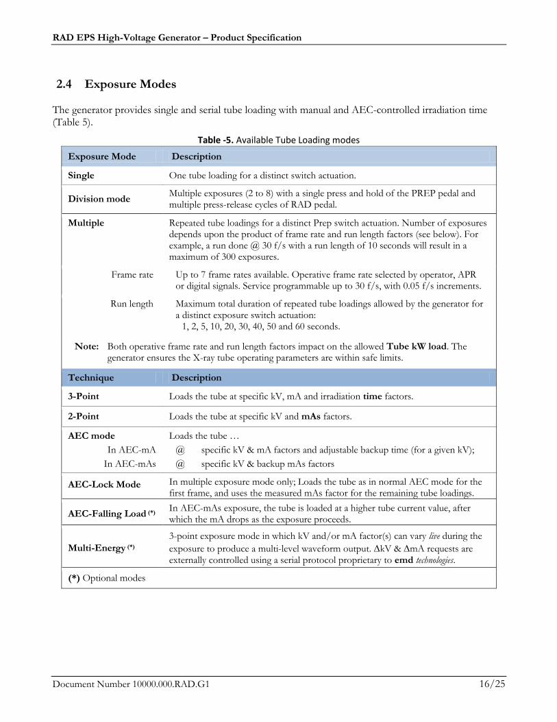
2.4 Exposure Modes The generator provides single and serial tube loading with manual and AEC-controlled irradiation time (Table 5).
Table -5. Available Tube Loading modes
Exposure Mode Description
Single One tube loading for a distinct switch actuation.
Division mode Multiple exposures (2 to 8) with a single press and hold of the PREP pedal and multiple press-release cycles of RAD pedal.
Multiple Repeated tube loadings for a distinct Prep switch actuation. Number of exposures depends upon the product of frame rate and run length factors (see below). For example, a run done @ 30 f/s with a run length of 10 seconds will result in a maximum of 300 exposures.
Frame rate Up to 7 frame rates available. Operative frame rate selected by operator, APR or digital signals. Service programmable up to 30 f/s, with 0.05 f/s increments.
Run length Maximum total duration of repeated tube loadings allowed by the generator for a distinct exposure switch actuation:
1, 2, 5, 10, 20, 30, 40, 50 and 60 seconds.
Note: Both operative frame rate and run length factors impact on the allowed Tube kW load. The generator ensures the X-ray tube operating parameters are within safe limits.
Technique Description
3-Point Loads the tube at specific kV, mA and irradiation time factors.
2-Point Loads the tube at specific kV and mAs factors.
AEC mode
In AEC-mA
In AEC-mAs
Loads the tube …
@ specific kV & mA factors and adjustable backup time (for a given kV);
@ specific kV & backup mAs factors
AEC-Lock Mode In multiple exposure mode only; Loads the tube as in normal AEC mode for the first frame, and uses the measured mAs factor for the remaining tube loadings.
AEC-Falling Load (*) In AEC-mAs exposure, the tube is loaded at a higher tube current value, after which the mA drops as the exposure proceeds.
Multi-Energy (*)
3-point exposure mode in which kV and/or mA factor(s) can vary live during the
exposure to produce a multi-level waveform output. kV & mA requests are externally controlled using a serial protocol proprietary to emd technologies.
(*) Optional modes

RAD EPS High-Voltage Generator – Product Specification
Document Number 10000.000.RAD.G1 17/25
2.5 AEC Mode The nominal shortest irradiation time for AEC exposure is 5 ms, at all x-ray tube current and x-ray tube voltage combinations. Maximum mAs: 600 mAs Optical density adjustment
Six clinically significant optical density corrections are provided with the AEC mode, varying from the standardized optical density N= 1.
Optical density correction (Ion chamber)
0.57 0.69 0.83 1 1.2 1.45 1.75
- 3 - 2 - 1 Normal + 1 + 2 + 3
75 % 82 % 90 % 100 % 110 % 121 % 133 %
Optical density correction (PM tube or photodiode)
Figure 9 – Useful range of optical densities in AEC mode. Ionization Chamber Interfaces
Two ion chambers are supported on the standard generator.
Three independent user-selectable fields (left, middle, right).
Ion Chamber Fields Film/Screen correction tables
Three film-screen correction tables: Compensation for density relating to film-screen kV curve characteristics. Compensation ranges from – 80 % up to + 130 % of phototiming level for 12 stations between 42 kV and 133 kV.
Other ion chamber interfaces are optional (Table 6). More AEC sensors can be interfaced, depending on the generator configuration.
Table -6. Additional Ion Chamber Interfaces (Option)
Expansion boards Number/Type of AEC Chamber
Photodiode Ion Chamber Fluoro board P/N 11030.001 2 conventional ion chambers
Universal Chambers Interface Board P/N 11002.001 1 conventional ion chamber
3 solid state chambers
RAD EPS High-Voltage Generator – Product Specification
Document Number 10000.000.RAD.G1 18/25
Photomultiplier tube interface This option requires the PM tube Fluoro board P/N 9822.01. The generator provides the PM tube gain circuit adjustment using a high voltage bias supply from about -200 V to about -950 V. Photodiode interface This option requires the Photodiode Ion Chamber Fluoro board P/N 11030.001. One BNC type connector is used for ABS/AEC feedback input from the photodiode device.
2.6 X-Ray Tube
2.6.1 X-Ray Tube Interface Type of Tubes Class 1 B (IEC Classification). Number of Tubes One X-ray tube standard; 2-tube configuration available as an option. Models Most popular X-ray tube models are supported through a built-in X-ray tube chart.
Other X-ray tube models may be added by the installer. Tube Filaments Focal spot number : 2 Current range : Up to 8.1 RMS amperes
Filament power : Maximum 100 watts Tube Derating The tube can be derated to extend its usable lifetime, to troubleshoot specific
conditions or other reasons.
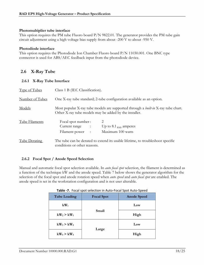
2.6.2 Focal Spot / Anode Speed Selection Manual and automatic focal spot selection available. In auto focal spot selection, the filament is determined as a function of the technique kW and the anode speed. Table 7 below shows the generator algorithm for the selection of the focal spot and anode rotation speed when auto speed and auto focal spot are enabled. The anode speed is set in the workstation configuration and is not user alterable.
Table -7. Focal spot selection in Auto-Focal Spot Auto-Speed
Tube Loading Focal Spot Anode Speed
kW1
Small
Low
kW2 > kW1 High
kW3 > kW2
Large
Low
kW4 > kW3 High
RAD EPS High-Voltage Generator – Product Specification
Document Number 10000.000.RAD.G1 19/25
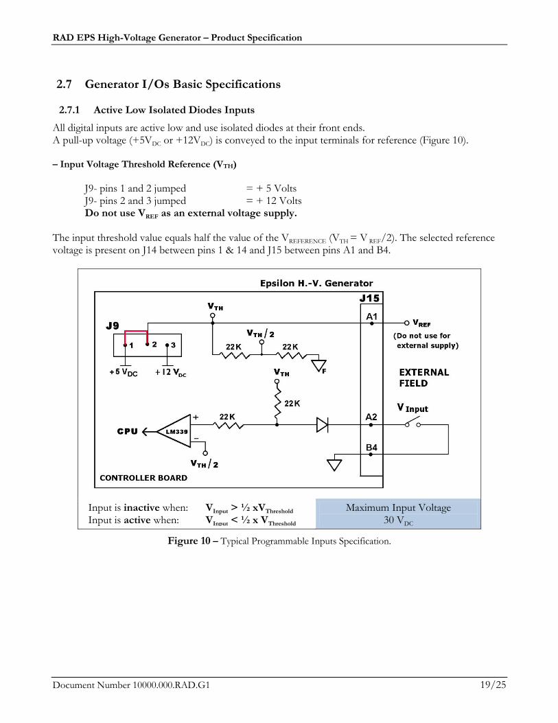
2.7 Generator I/Os Basic Specifications
2.7.1 Active Low Isolated Diodes Inputs
All digital inputs are active low and use isolated diodes at their front ends. A pull-up voltage (+5VDC or +12VDC) is conveyed to the input terminals for reference (Figure 10). – Input Voltage Threshold Reference (VTH)
J9- pins 1 and 2 jumped = + 5 Volts J9- pins 2 and 3 jumped = + 12 Volts Do not use VREF as an external voltage supply. The input threshold value equals half the value of the VREFERENCE (VTH = V REF/2). The selected reference voltage is present on J14 between pins 1 & 14 and J15 between pins A1 and B4.
Input is inactive when: VInput > ½ xVThreshold Input is active when: VInput < ½ x VThreshold
Maximum Input Voltage 30 VDC
Figure 10 – Typical Programmable Inputs Specification.
RAD EPS High-Voltage Generator – Product Specification
Document Number 10000.000.RAD.G1 20/25
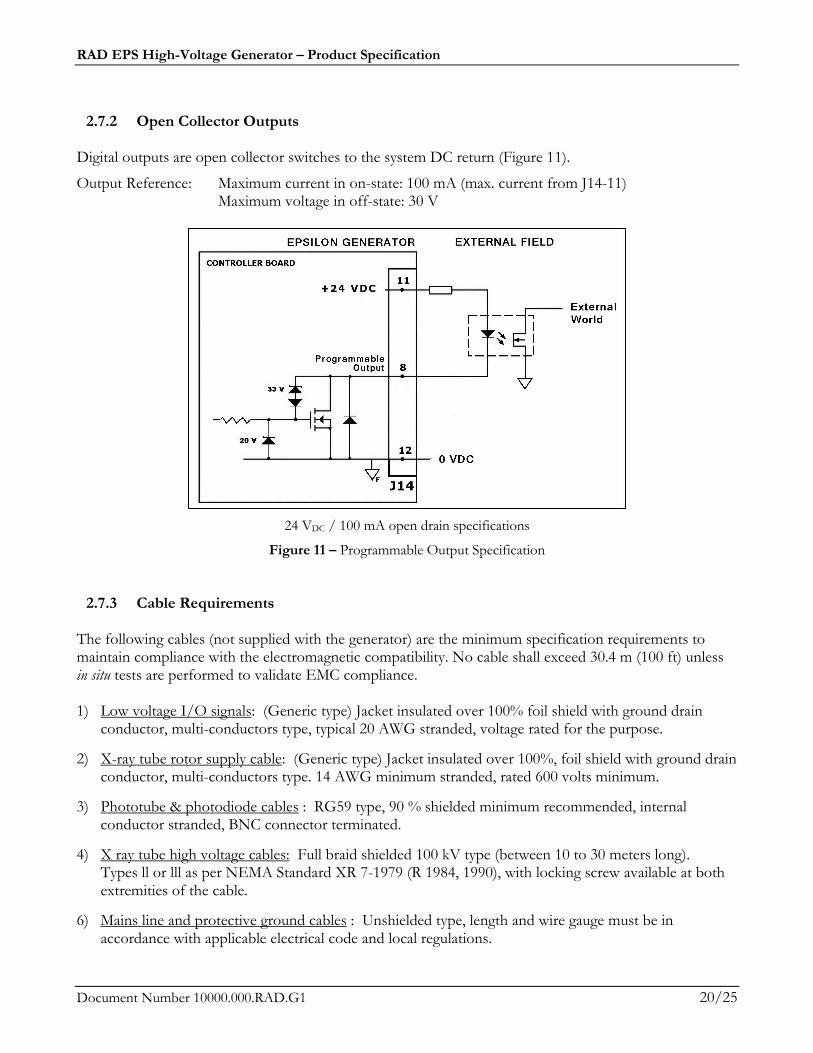
2.7.2 Open Collector Outputs Digital outputs are open collector switches to the system DC return (Figure 11).
Output Reference: Maximum current in on-state: 100 mA (max. current from J14-11) Maximum voltage in off-state: 30 V
24 VDC / 100 mA open drain specifications
Figure 11 – Programmable Output Specification
2.7.3 Cable Requirements The following cables (not supplied with the generator) are the minimum specification requirements to maintain compliance with the electromagnetic compatibility. No cable shall exceed 30.4 m (100 ft) unless in situ tests are performed to validate EMC compliance. 1) Low voltage I/O signals: (Generic type) Jacket insulated over 100% foil shield with ground drain
conductor, multi-conductors type, typical 20 AWG stranded, voltage rated for the purpose.
2) X-ray tube rotor supply cable: (Generic type) Jacket insulated over 100%, foil shield with ground drain conductor, multi-conductors type. 14 AWG minimum stranded, rated 600 volts minimum.
3) Phototube & photodiode cables : RG59 type, 90 % shielded minimum recommended, internal conductor stranded, BNC connector terminated.
4) X ray tube high voltage cables: Full braid shielded 100 kV type (between 10 to 30 meters long). Types ll or lll as per NEMA Standard XR 7-1979 (R 1984, 1990), with locking screw available at both extremities of the cable.
6) Mains line and protective ground cables : Unshielded type, length and wire gauge must be in accordance with applicable electrical code and local regulations.
RAD EPS High-Voltage Generator – Product Specification
Document Number 10000.000.RAD.G1 21/25
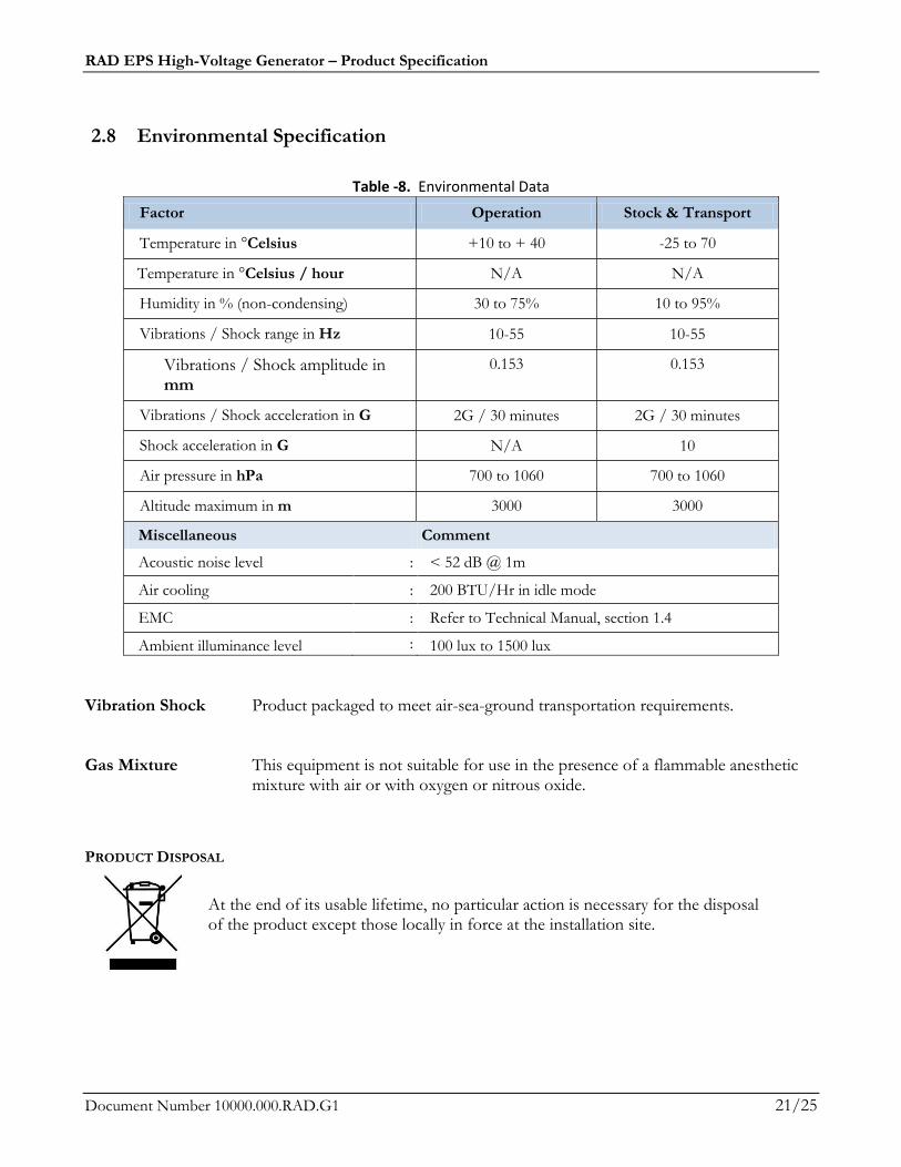
2.8 Environmental Specification
Table -8. Environmental Data
Factor Operation Stock & Transport
Temperature in °Celsius +10 to + 40 -25 to 70
Temperature in °Celsius / hour N/A N/A
Humidity in % (non-condensing) 30 to 75% 10 to 95%
Vibrations / Shock range in Hz 10-55 10-55
Vibrations / Shock amplitude in mm
0.153 0.153
Vibrations / Shock acceleration in G 2G / 30 minutes 2G / 30 minutes
Shock acceleration in G N/A 10
Air pressure in hPa 700 to 1060 700 to 1060
Altitude maximum in m 3000 3000
Miscellaneous Comment
Acoustic noise level : < 52 dB @ 1m
Air cooling : 200 BTU/Hr in idle mode
EMC : Refer to Technical Manual, section 1.4
Ambient illuminance level : 100 lux to 1500 lux
Vibration Shock Product packaged to meet air-sea-ground transportation requirements. Gas Mixture This equipment is not suitable for use in the presence of a flammable anesthetic
mixture with air or with oxygen or nitrous oxide.
PRODUCT DISPOSAL
At the end of its usable lifetime, no particular action is necessary for the disposal of the product except those locally in force at the installation site.
RAD EPS High-Voltage Generator – Product Specification
Document Number 10000.000.RAD.G1 22/25
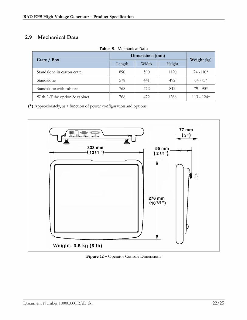
2.9 Mechanical Data
Table -9. Mechanical Data
Crate / Box Dimensions (mm)
Weight (kg) Length Width Height
Standalone in carton crate 890 590 1120 74 -110*
Standalone 578 441 492 64 -75*
Standalone with cabinet 768 472 812 79 - 90*
With 2-Tube option & cabinet 768 472 1268 113 - 124*
(*) Approximately, as a function of power configuration and options.
Figure 12 – Operator Console Dimensions
RAD EPS High-Voltage Generator – Product Specification
Document Number 10000.000.RAD.G1 23/25
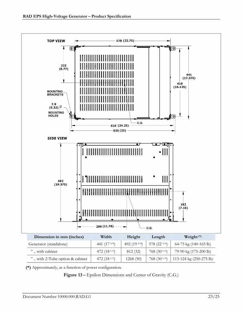
Dimension in mm (inches) Width Height Length Weight (*)
Generator (standalone) 441 (17 3/8) 492 (19 3/8) 578 (22 3/4) 64-75 kg (140-165 lb)
” .. with cabinet 472 (18 1/2) 812 (32) 768 (30 1/4) 79-90 kg (175-200 lb)
” .. with 2-Tube option & cabinet 472 (18 1/2) 1268 (50) 768 (30 1/4) 113-124 kg (250-275 lb)
(*) Approximately, as a function of power configuration.
Figure 13 – Epsilon Dimensions and Center of Gravity (C.G.)
RAD EPS High-Voltage Generator – Product Specification
Document Number 10000.000.RAD.G1 24/25
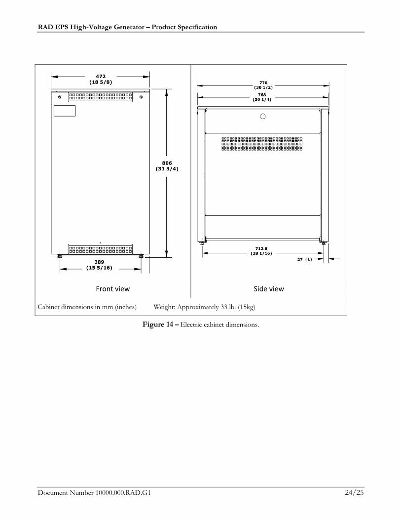
Front view Side view
Cabinet dimensions in mm (inches) Weight: Approximately 33 lb. (15kg)
Figure 14 – Electric cabinet dimensions.
RAD EPS High-Voltage Generator – Product Specification
Document Number 10000.000.RAD.G1 25/25
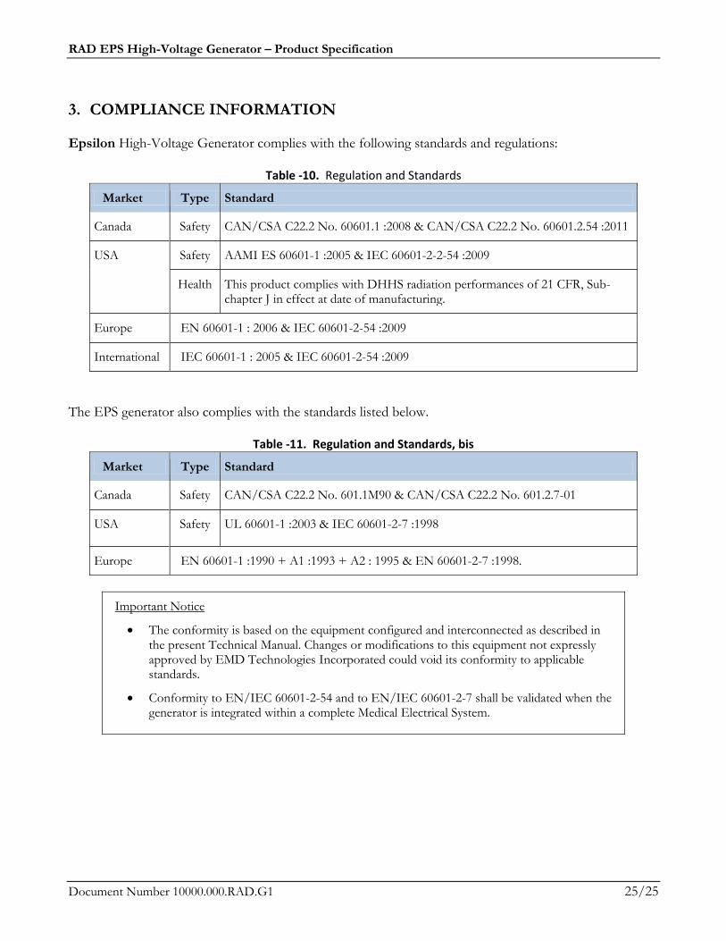
3. COMPLIANCE INFORMATION
Epsilon High-Voltage Generator complies with the following standards and regulations:
Table -10. Regulation and Standards
Market Type Standard
Canada Safety CAN/CSA C22.2 No. 60601.1 :2008 & CAN/CSA C22.2 No. 60601.2.54 :2011
USA Safety AAMI ES 60601-1 :2005 & IEC 60601-2-2-54 :2009
Health This product complies with DHHS radiation performances of 21 CFR, Sub-chapter J in effect at date of manufacturing.
Europe EN 60601-1 : 2006 & IEC 60601-2-54 :2009
International IEC 60601-1 : 2005 & IEC 60601-2-54 :2009
The EPS generator also complies with the standards listed below.
Table -11. Regulation and Standards, bis
Market Type Standard
Canada Safety CAN/CSA C22.2 No. 601.1M90 & CAN/CSA C22.2 No. 601.2.7-01
USA Safety UL 60601-1 :2003 & IEC 60601-2-7 :1998
Europe EN 60601-1 :1990 + A1 :1993 + A2 : 1995 & EN 60601-2-7 :1998.
Important Notice
The conformity is based on the equipment configured and interconnected as described in the present Technical Manual. Changes or modifications to this equipment not expressly approved by EMD Technologies Incorporated could void its conformity to applicable standards.
Conformity to EN/IEC 60601-2-54 and to EN/IEC 60601-2-7 shall be validated when the generator is integrated within a complete Medical Electrical System.