Embed Size (px)
Citation preview
f A T E C H N I C A L
M E M O R A N D U M
RADIAL INFLOW TURBINE PERFORMANCE WITH AN IIXIT
DIFFUSER DESIGNED FOR LINEAR STATIC PRESS URL VARIATION
by Harold E. Rohlik, Milton G. Kofskey , and Wil l iam 5 . Nusbaum Lewis Research Center
Cleveland, Ohio
September 1970
https://ntrs.nasa.gov/search.jsp?R=19700032591 2018-09-06T00:06:36+00:00Z

This information is being published in prelimi- nary form in order to expedite its early release,
ABSTRACT
Two diffusers were designed with the same area ratio but different variations between the inlet and exit, The first, with a cylindrical inner body and conical outer wall provided a rapid r i se in static pressure at the inlet, The second diffuser -was designed for a linear increase in static pressure from inlet to exit, Each diffuser was tested a s part of the tur- bine with cold argon at design Reynolds number, Overall turbine total- to-total efficiency was increased from 0,894 to 0,905 in changing from the conical diffuser to the linear static pressure diffuser, The diffuser loss was reduced from 0,019 to 0,008 in t e rms of overall total-to-total turbine efficiency,
RADIAL INFLOW TURBI1SE PERFOBIUNCE WITH AN EXIT
DIFFUSER DESIGNED FOR UNEAR
STATIC PRESSURE VARIATION
by Harold E. Rohlik, Milton G, Kofskey, and William J, Nusbaum
Lewis Research Center National Aeronautics and Space Administration
Cleveland, Ohio
SUMMARY
Two turbine exit diffusers were designed for the 2 to 10 kW Brayton Rotating Unit. The original had a cylindrical inner body and a conical outer wall. The second, designed with the same area ratio and slightly greater length, had a tapered inner bady and an outer wall contoured to provide a linear increase in static pressure,
Both diffusers were operated a s part of the turbine assembly and at design equivalent speed and Reynolds number, At design pressure ratio, equivalent speed, and Reynolds number, the second diffuser provided an overall turbine efficiency one point higher than did the original, This im- provement indicates a potential increase of 2, 8 percent in system electrical net power output.
Static pressure measurements and diffuser exit surveys indicate that the flow separated from the inner body causing a slight increase in velocity and hence slight reductions in diffuser efficiency and effectiveness. Diffuser per- formance might be further improved by inhibiting this separation,
INTRODUCTION
Turbomachinery components designed for Brayton cycle space power systems a r e being investigated to determine performance characteristics. Typically, a point in turbine performance is equivalent to about percent % in net system power output while a point in compressor efficiency is equiva-
1 lent to about 1- percent, There is therefore considerable incentive to achieve 2 maximum component efficiencies,
Components of the Brayton Rotating Unit (BRU) power generation system have been under investigation for several years at the Lewis Research Center" A 4, 97-inch diameter turbine drives the compressor and the alternator of this 2 to 10 kW system, The turbine assembly included a diffuser with a cylin- drical inner body and a conical outer wall, The area ratio of the diffuser was 2, 65, The turbine and diffuser designs a r e described in the contractor's re- port, reference 1, The turbine, with and without the diffuser, was tested in cold argon and the investigation was reported in reference 2, Results indica- ted that the diffuser loss was 0, 02 in overall total-to-total turbine efficiency, 1, 4 times the design loss,
Design flow characteristics in the diffuser were then examined with a one- dimensional calculation of velocity and static pressure a s functions of flow area and total pressure loss, An alternate design was made in order to change the maximum deceleration rate and thereby reduce the diffusion loss, This dif- fuser was designed to provide a linear variation in static pressure through the diffuser, The rate of deceleration is much smaller near the inlet than in the original diffuser,
The second diffuser was built and tested a s a part of the research turbine, This report describes the second diffuser design, its performance, and over- al l turbine performance, Design characteristics and performance of the ori- ginal and the second diffusers a r e compared,
H isentropic specific work (based on total pressure ratio) (ft-lb)/lb
Ah specific work, Btullb
N turbine speed rpm
specific speed, N Q ~ / ~ / ~ ~ / ~ ~ rpm (ft) 3/4/sec1/2
P pressure, psia
8 volume flow (based on exit conditions), ft3/sec
Re Reynolds number ~ / ~ r +
r radius, f t
T 0 absolute temperature, R
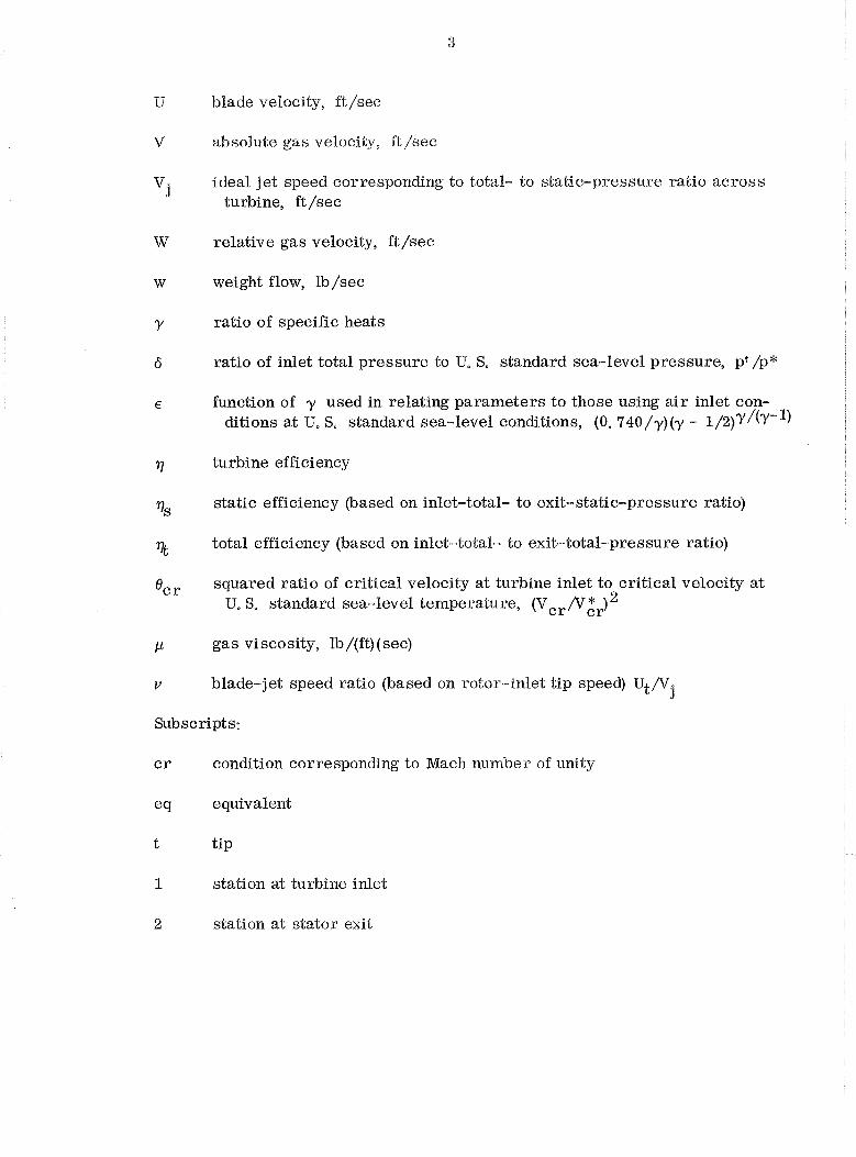
U blade velocity, ft/sec
V absolute gas velocity, ft/sec
v j ideal jet speed corresponding to total- to static-pressure ratio across
turbine, ft/sec
W relative gas velocity, ft/sec
w weight flow, lb/sec
Y ratio of specific heats
6 ratio of inlet total pressure to U, S. standard sea-level pressure, pp /p*
E function of y used in relating parameters to those using a i r inlet con- ditions at U. S. standard sea-level conditions, (0. 740 /y) (y - 1 / 2 ) ~ / ( ~ - ~ )
17 turbine efficiency
77s static efficiency (based on inlet-total- to exit-static-pressure ratio)
% total efficiency (based on inlet-total- to exit-total-pressure ratio)
0c r squared ratio of critical velocity at turbine inlet to critical velocity a t U. S. standard sea-level temperature, (Vcr/Vzr) 2
P gas viscosity, lb/(ft) (see)
v blade-jet speed ratio (based on rotor-inlet tip speed) Ut/V. 3
Subscripts:
c r condition corresponding to Mach number of unity
e cl equivalent
t tip
1 station at turbine inlet
2 station at stator exit
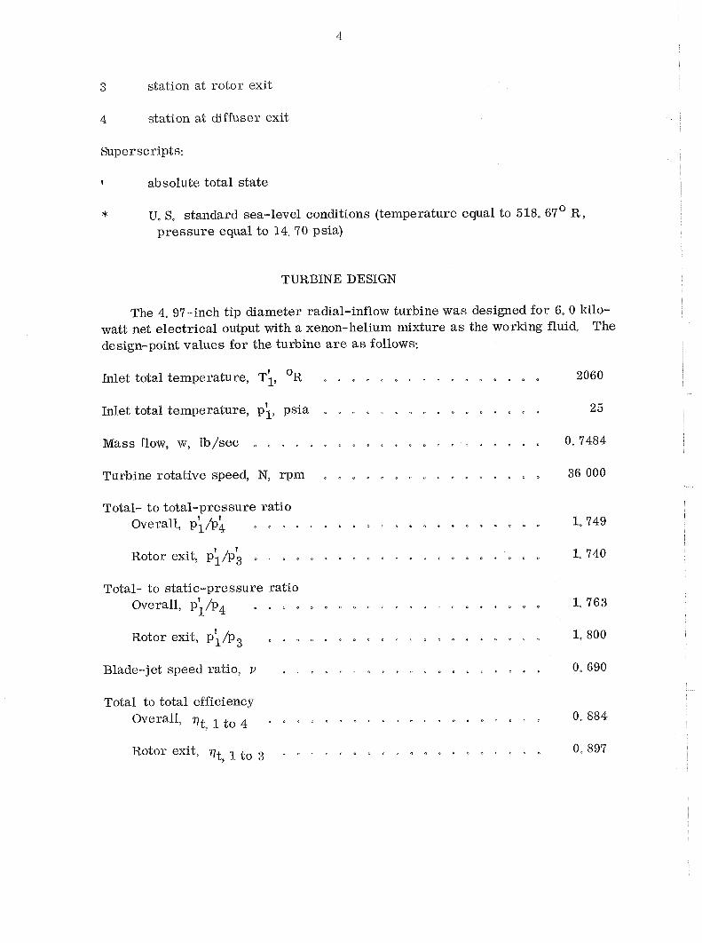
3 station at rotor exit
4 station at diffuser exit.
Superscripts:
t absolute total state
* U, S, standard sea-level conditions (temperature equal to 518,67O R , pressure equal to f4,70 psia)
TURBINE DESIGN
The 4, 97-inch tip diameter radial-inflow turbine was designed for 6,O kilo- watt net electrical output with a xenon-helium mixture as the working fluid, The design-point values for the turbine a r e a s follows:
Inlet total temperature, T;, OR . . . . . . . . . . . . . . . . 2060
Inlet total temperature, pi , psia . . . . . . . . . . . . . . . . 2 5
. . . . . . . . . . . . . . . . . . . . . Mass flow, w, lb/sec 0.7484
. . . . . . . . . . . . . . . . . Turbine rotative speed, N, rpm 36 000
Total- to total-pressure ratio . . . . . . . . . . . . . . . . . . . . . . Overall, p;/pk
f . . . . . . . . . . . . . . . . . . . . . Rotor exit,
Total- to static-pressure ratio Overall, p;/p4 . . . . . . . . . . . . . . . . . . . . . 1,763
Rotor exit, p;/p3 . . . . . . . . . . . . . . . . . . . . . 1,800
Blade-jet speed ratio, v . . . . . . . . . . . . . . . . . . . 0, 690
Total to total efficiency Overall, qt to . + + . " . , ,
9
Rotor exit, qt, I . a . " " a . . a
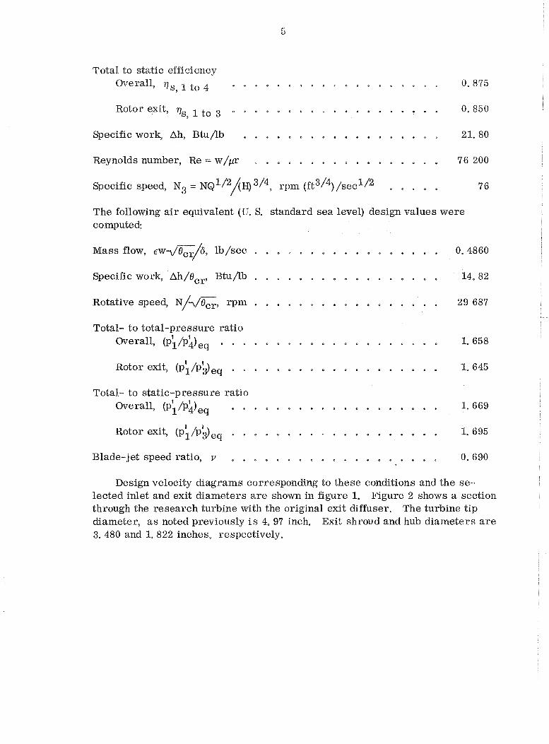
Total to static efficiency . . . . . . . . . . . . . . . . . . . Overall9 rls. 1 to 4 0. 875
. . . . . . . . . . . . . . . . . . . Rotorexit. 7, 0.850 9 .
. . . . . . . . . . . . . . . . . . Specific work. Ah. Btu/lb 21.80
. . . . . . . . . . . . . . . . . Reynolds number. Re = w/pr 76 200
Specific speed. N3 = N Q ' / ~ ~ H ) 3/49 rpm (ft3/4) /sec1l2 . . . . . 76
The following a i r equivalent (U. S . standard sea level) design values were computed:
. . . . . . . . . . . . . . . . . Mass flow. E~7&p./6. lb/sec 0.4860
. . . . . . . . . . . . . . . . . Specific work. Ah/Bcr. Btu/lb 14.82
. . . . . . . . . . . . . . . . . Rotative speed. N/?/Fr. rpm 29 687
Total- to total-pressure ratio . . . . . . . . . . . . . . . . . . . . Overall. (p;/pk), 1.658
Total- to static-pressure ratio . . . . . . . . . . . . . . . . . . . Overall. ( P ; / P ~ ) ~ ~ 1.669
. . . . . . . . . . . . . . . . . . . Blade-jet speed ratio. v 0.690
Design velocity diagrams corresponding to these conditions and the se- lected inlet and exit diameters a r e shown in figure 1 . Figure 2 shows a section through the research turbine with the original exit diffuser . The turbine tip diameter. a s noted previously is 4 . 97 inch . Exit shroud and hub diameters a r e 3 . 480 and 1 . 822 inches. respectively .
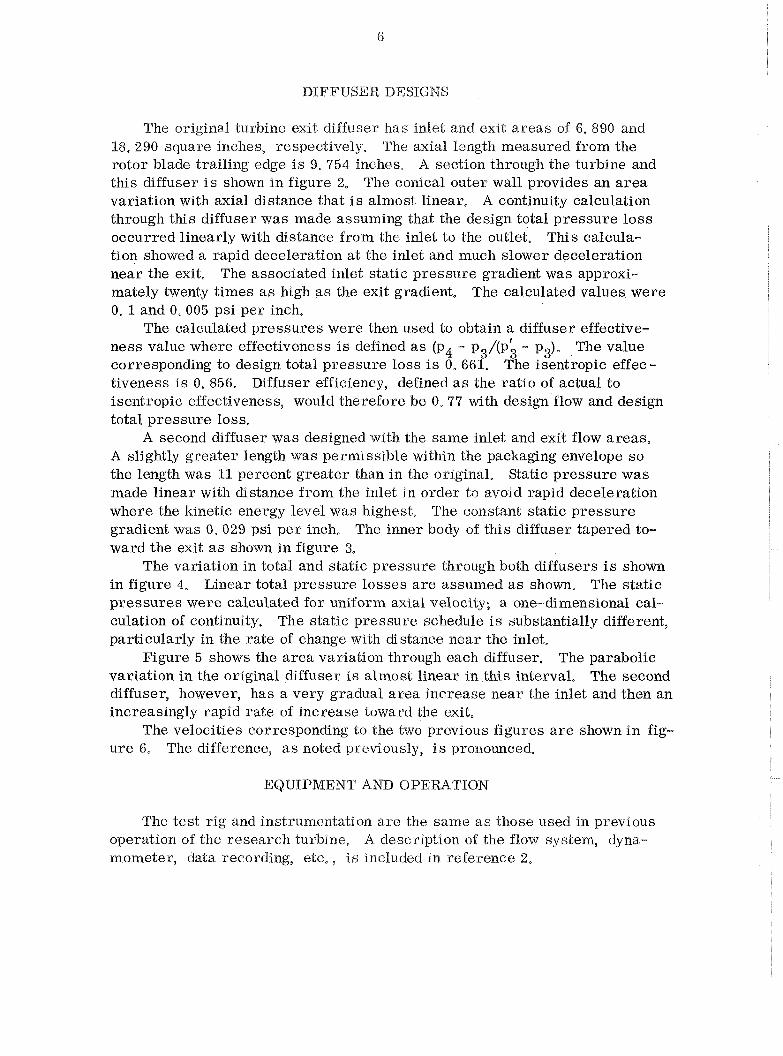
DIFFUSER DESIGNS
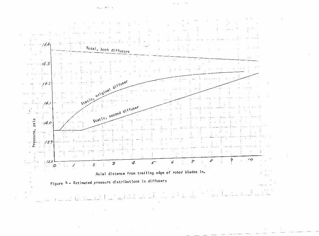
The original turbine exit diffuser has i d e t and exit areas of 6. 890 and 18. 290 square inches, respectively. The axial length measured from the rotor blade trailing edge is 9,754 inches. A section through the turbine and this diffuser is shown in figure 2. The conical outer wall provides an a rea variation with axial distance that is almost linear, A continuity calculation through this diffuser was made assuming that the design total pressure loss occurred linearly with distance from the inlet to the outlet, This calcula- tion showed a rapid deceleration a t the inlet and much slower deceleration near the exit, The associated inlet static pressure gradient was approxi- mately twenty times as high a s the exit gradient, The calculated values were 0. 1 and 0.005 psi per inch.
The calculated pressures were then used to obtain a diffuser effective- ness value where effectiveness is defined a s (pq - p3/(p\ - p3). The value corresponding to design total pressure loss is 0, 661. The isentropic effec- tiveness is 0. 856, Diffuser efficiency, defined a s the ratio of actual to isentropic effectiveness, would therefore be 0, 77 with design flow and design total pressure loss,
A second diffuser was designed with the same inlet and exit flow areas, A slightly greater length was permissible within the packaging envelope so the length was 11 percent greater than in the original, Static pressure was made linear wit11 distance from the inlet in order to avoid rapid deceleration where the kinetic energy level was highest. The constant static pressure gradient was 0.029 psi per inch, The inner body of this diffuser tapered to- ward the exit a s s h o m in figure 3,
The variation in total and static pressure through both diffusers is s h o m in figure 4, Linear total pressure losses a r e assumed a s shom, The static pressures were calculated for uniform axial velocity; a one-dimensional cal- culation of continuity. The static pressure schedule is substantially different, particularly in the rate of change with distance near the inlet,
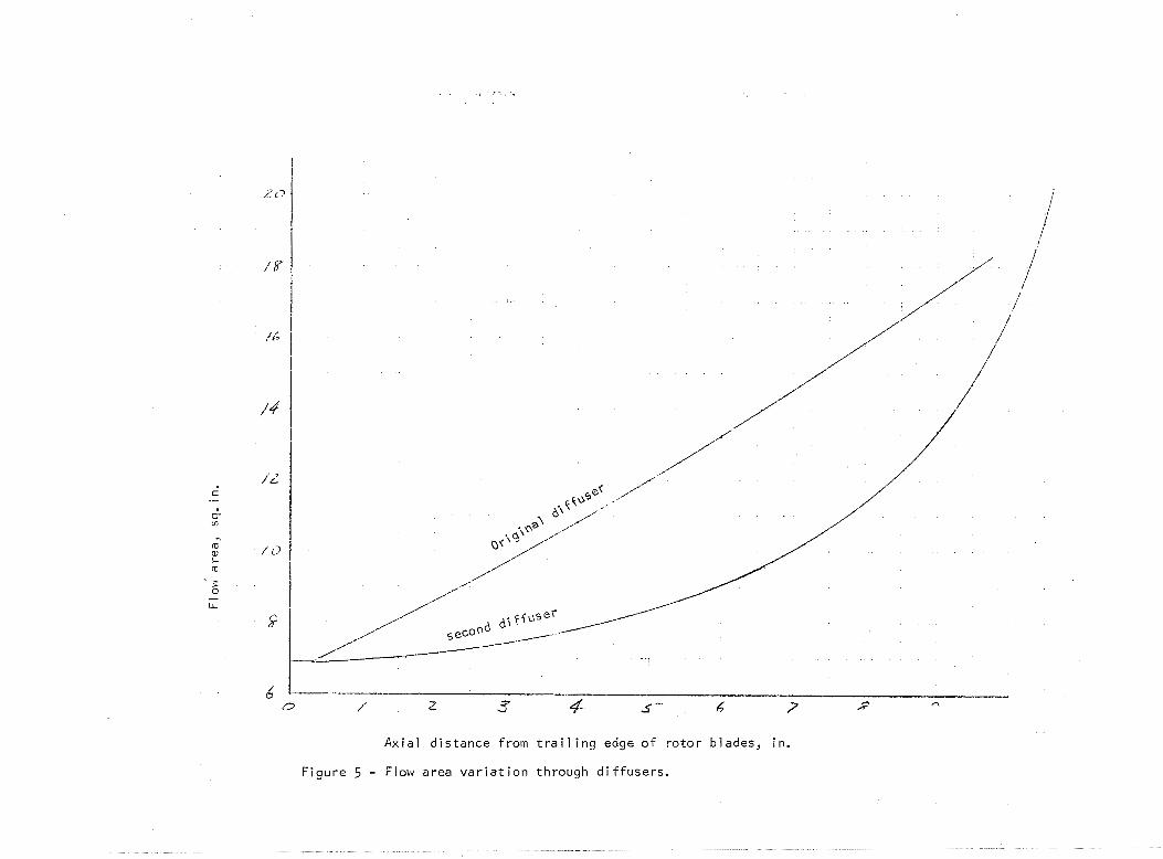
Figure 5 shows the area variation through each diffuser. The parabolic variation in the original diffuser is almost linear in this interval, The second diffuser, however, has a very gradual area increase near the inlet and then an increasingly rapid mte of increase toward the exit,
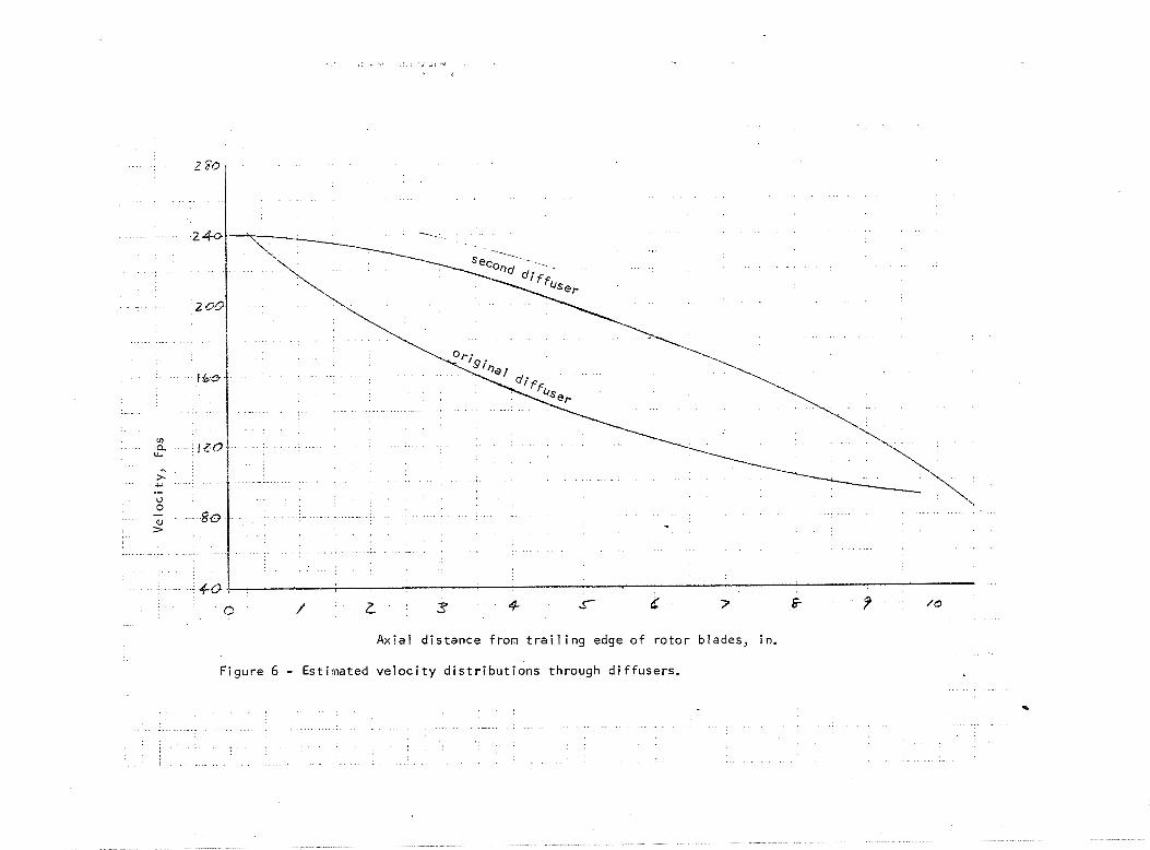
The velocities corresponding to the two previous figures a r e shown i n fig- ure 6, The difference, a s noted previously, is pronounced.
EQUIPMENT AND OPEMT1ON
The test r9g and instrumentation a re the same a s those used in previous operation of the research turbine, A description of the flow system, dyna- mometer, data recording, etc, , is included in reference 2,
The diffusers discussed in this repol5 were, tested only a s p a d s of the turbine, never a s india7iden8wl c*ornpo~~elrls, Performance measurements there- fore correspovld to a diffuser inlel flow cor~dition that Bnchdes high turbulence and radial gradients in flow, pressure, temperature, and flow angle.
Test operation wit11 the second diffrrser was run in cold argon with h o inlet pressures, 7.0 psia and 20 psia. 7.0 psia with the test turbine inlet tem- perature of 610' R provides design Reynolds number. Evaluation of diffuser performance for this low pressure operation depends on small differences in measured pressures, Consequently, additional runs were made at 20 psia to substantiate the results obtained at 7 psia.
RESULTS AND DISCUSSION
A second turbine exit diffuser was designed in an effort to improve over- all turbine performance, Diffuser and overall turbine performance were determined during operation over ranges of pressure ratio and speed. Test runs were made of two pressure levels; 9.0 psia in order to provide design Reynolds number, and 20 psia to increase the certainty of the pressure meas- urements. There was no noticeable difference in calculated performance de- termined from measurements a t the two pressure levels. The performance curves in this report a r e from the design Reynolds number operation.
Overall. Performance
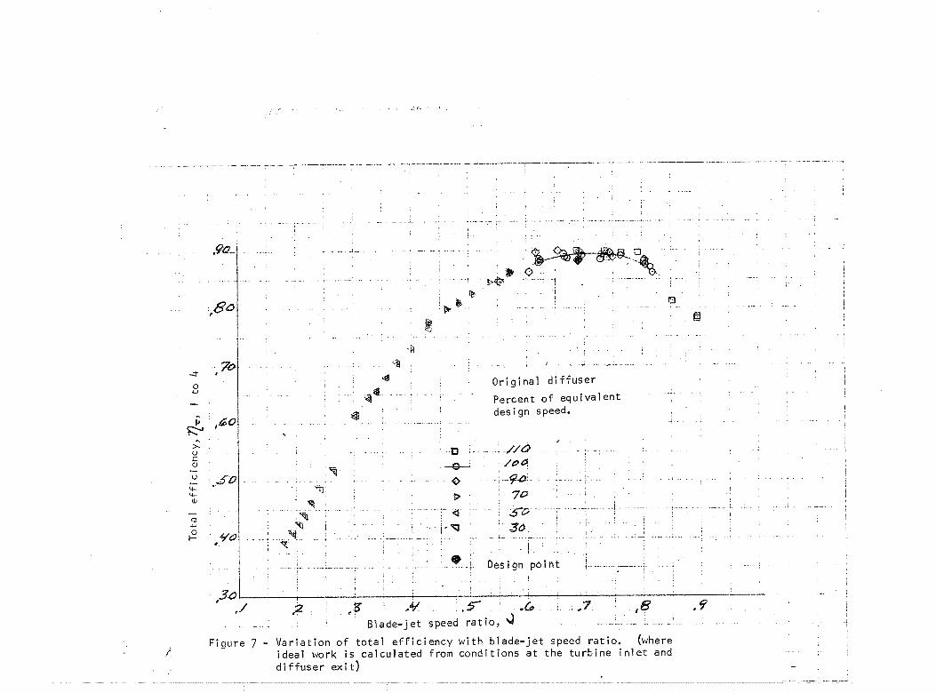
Overall turbine total efficiency with the original diffuser is shown in fig- ure 7 a s a function of blade-jet speed ratio. This figure is taken from refer- ence 2 (fig, 12(b)) and includes ranges of pressure ratio and speed, The solid line is faired through the design speed data points. The curve peaks a t 0,894 near the design blade-jet speed ratio of 0. 69, This is 0.01 higher than the design value of 0.884. The corresponding efli1e;lency based on rotor exit total pressure was 0. 913, The diffusion penalty was therefore 0.0 19 in total ef- ficiency.
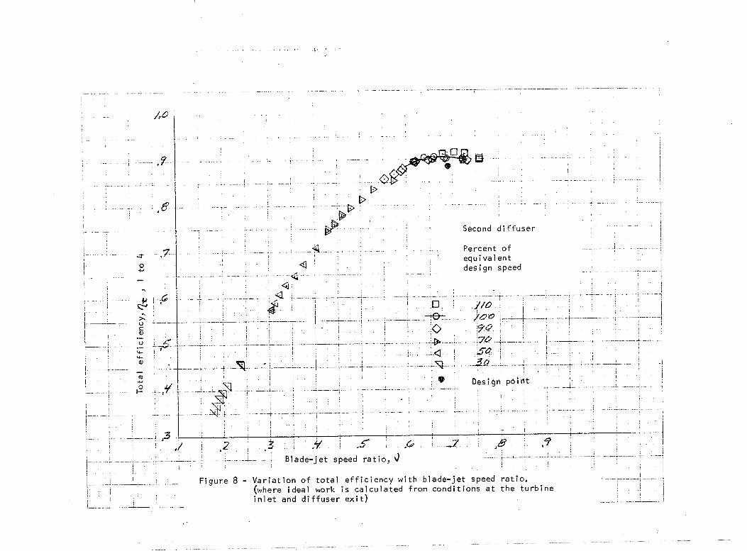
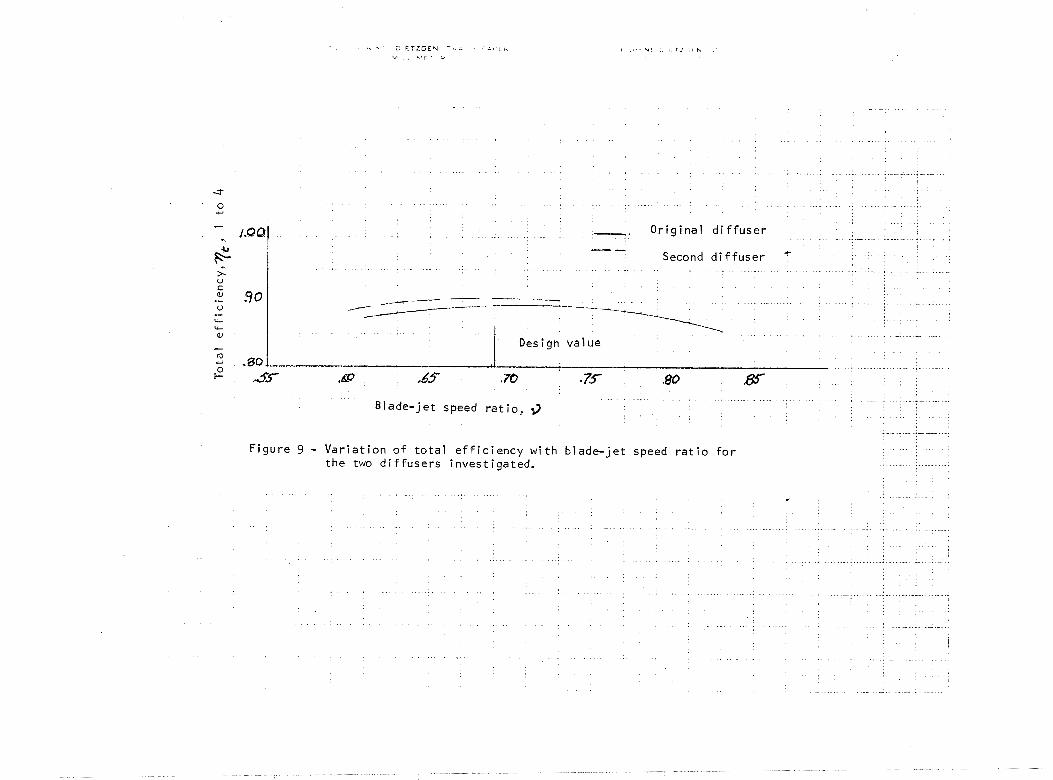
Figure 8 shows in the same manner per4'ormance with the second diffuser, The peak efficiency of 0.905 occurs a t the design blade-jet speed ratio. The diffusion penalty indicated here is 0.008. This increase in overall turbine ef- ficiency represents a potential 2- 8 percent increase in net alternator power output. The design speed curves fur both diffusers a r e in figure 9 for corn- parison. Table I summarizes diffuser and overall perfurmanee.
Static Pressure Distrihuti on
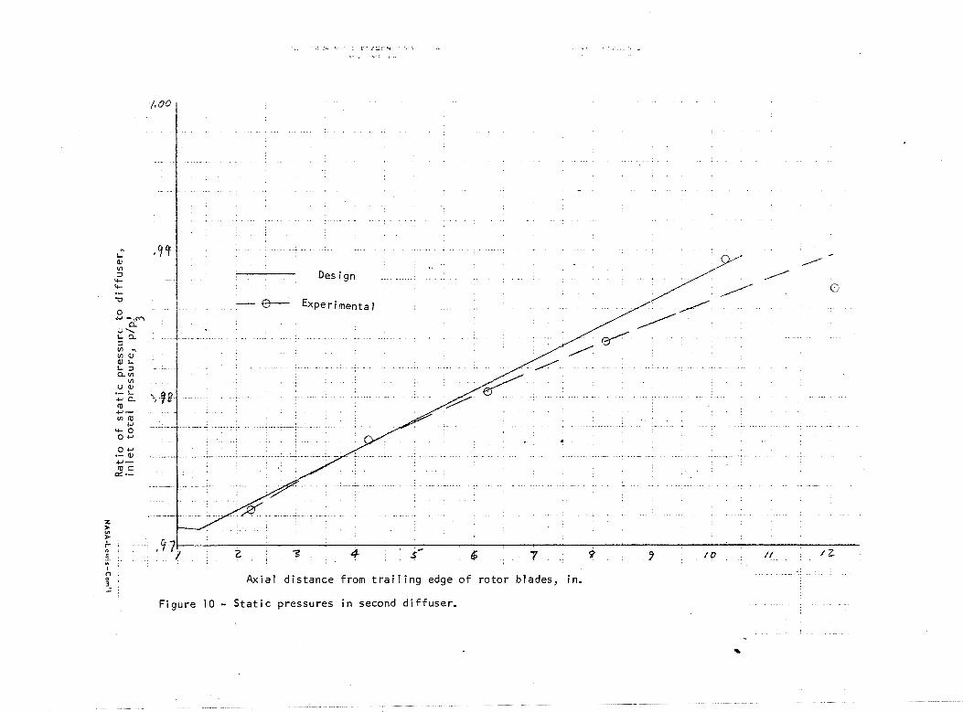
Static pressures on the vvall of the second diffnssr were measured at five static: tap locations between the rotor exit and the d i f f ~ ~ s e r exit: and one locatjon domstream, Figure 10 shows pressures medsured at design speed, pressure
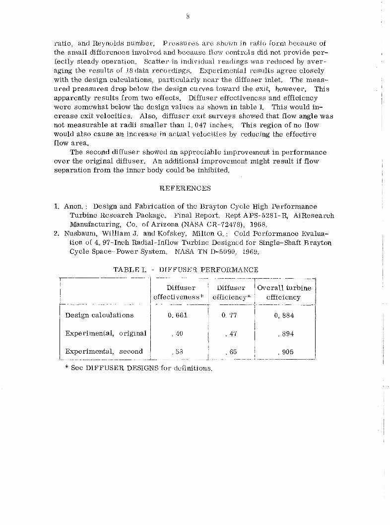
ratio, and Reynolds number, Pressures a r e sliutm in ratio form because of the small differences involved and because flow controls did not provide per- fectly steady operation, Scatter in indrvidual readings was reduced by aver- aging the results of 18 data recordings, Experimental results agree closely with the design calculations, particularly near the diffuser inlet, The meas- ured pressures drop below the design curves toward the exit, however. This apparently results from two effects. Diffuser effectiveness and efficiency were somewhat below the design values a s shown in table I, This would in- crease exit velocities, Also, diffuser exit sumeys showed that flow angle was not measurable a t radii smaller than 1,047 inches, This region of no flow would also cause an increase in actual velocities by reducing the effective flow area,
The second diffuser showed an appreciable irnproverrnent in performance over the original diffuser, An additional improvement might result if flow separation from the inner body could be inhibited,
REFERENCES
I. Anon, : Design and Fabrication of the Brayton Cycle Wgh Performance Turbine Research Package, Final Report, Rep'c APS-5281-R, AiResearch Manufacturing, Co, of Arizona (NASA CR-92478), 1968,
2. Nusbaum, William J, and Kofskey, Mlton G, : Cold Performance Evalua- tion of 4,537-Inch Radial-Inflow Turbine Designed for Single-Shaft Brayton Cycle Space-Power System, NASA TN B- 5090, 9969,
TABLE 1, - DIFFUSE iZ PERFORMANCE 1
* See DIFFTJSER DESIGNS for definitions.
Design calculations
Experimental, original
Experimental, second 1 -- +- - - -- -- -- --
I Diffuser 4 Diffuser ~ e r a l l
effectiveness* efficiencyv - - - --!r effi ciency - -
0,661 1 0 77 0- 884 I
40
-53
I "47
65
. 894
, 905
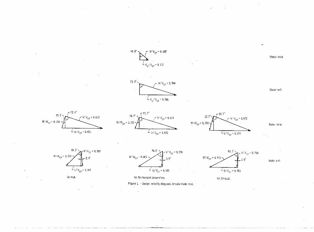
Stator in let
Stator exit
r 72.9' r 71.7"
Rotor in let
UIVcr = 0.631 " U I V,, - 0.631 'UIV,, = 0.631
(a) Hub. Ib) 50-Percent streamline.
Figure L - Design velocity diagrams (inside blade row).
(c ) Shroud.
Rotor exit
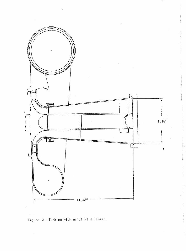
F igu re 2 - Turb ine w i t h o r i g i n a l d i f f u s e r ,

F i g u r e 3 - T u r b i n e w i t h second d i f f u s e r .
- - -- _. Total, both d i f furers --------- ----------
-------- -- ---
/4,3 - .
Axial distance from trail ing edge o f rotor blades in.
Figure 4 - Estimated pressure distributions in diffusers
A x i a l d i s t a n c e f rom t r a i l i n g edge o f r o t o r blades, in.
F i g u r e 5 - Flow area v a r i a t i o n th rough d i f f u s e r s .
Axial distance from trail ing edge o f rotor blades, in.
Figure 6 - Estimated velocity distributions through diffusers.
F i g u r e 7 - V a r i a t i o n o f t o t a l e f f i c i e n c y w i t h b l a d e - j e t speed r a t i o . (where / i d e a l work i s c a l c u l a t e d f rom c o n d i t i o n s a t t h e t u r b i n e i n l e t and
d i f f u s e r e x i t )
- - - - L - - - - -- - . - - -- - - A -
I
I 1
w9Q-! - ; - -
I - - -- 2
8 0 cs I
,8~
3 b a 8
0 w -
,so. I? -. >. u f a, .- .fl 3-0 4 - . 4- a,
- m w
t-" ,YO
,230
- - - ' €4 -7 * - . ,
b P~
0 - *- 1
b a I
1
d
;B 1 1 - _ . 4 j C
& O r i g i n a l d i f f u s e r I
3@ . -
Percent o f e q u i v a l e n t des ign speed. I
9 - - 4
r'
D . . //d * - - I I
100 'g
-8- - 4 4 - -: . I
-rl 0
7a ' 0 , I T
5t'- , - - 1 - 4 2 4- - A - <
I - Q I 3 - 1 ,
I 1 1-fJ 3 d '
3 -. +. -__,. - -- - , - -1- - -- - - I .
a T 1 1
1
- - - .--- , - besign p o i n t , 1 - ' I
I
! -- ,/ I ,=s I .3 .."J ,s ,& * 7 ,B .(a
B lade - je t speed r a t i o , 3 . - !
- -
F i g u r e 9 - V a r i a t i o n o f t o t a l e f f i c i e n c y w i t h b l a d e - j e t speed r a t i o f o r t h e two d i f f u s e r s i nves t i ga ted .
.- -
- . - - - --
- . .
- -
- * -
- .- - 3
0
I
+J - 1.0~2
i+ >. U K
.a, 30 U .- rC 4- aJ - ro - -60
, O r i g i n a l d i f f u s e r - . , - - - - -- Second d i f f u s e r *
_ - - - - -- -- *-- --__- . .
--l----------- -- *--I A- Design v a l u e
A"--... P..
,fQ .70 r-" 3s ' .65" -75 .80 85 . -- .
B l a d e - j e t speed r a t i o , 9
Axial distance from trailing edge of rotor blades, in.
Figure 10 - Static pressures in second diffuser. . .