Embed Size (px)
Citation preview

Radiation Exposure for Radiation Exposure for CR/DR CR/DR -- What, Why, What, Why, Where, How?Where, How?
Melissa C. Martin, M.S., FACRMelissa C. Martin, M.S., FACRCSRT Annual Conference CSRT Annual Conference November 13, 2011November 13, 2011CedarsCedars--Sinai Medical Center Sinai Medical Center -- Los AngelesLos Angeles
Learning ObjectivesLearning Objectives
Explain technology of available and future Explain technology of available and future digital radiography technologydigital radiography technologyUnderstand underlying system operation and Understand underlying system operation and characteristicscharacteristicsCompare CR/DR image acquisition and Compare CR/DR image acquisition and display advantages / disadvantagesdisplay advantages / disadvantagesDiscuss Methods to monitor Patient Discuss Methods to monitor Patient ExposuresExposures
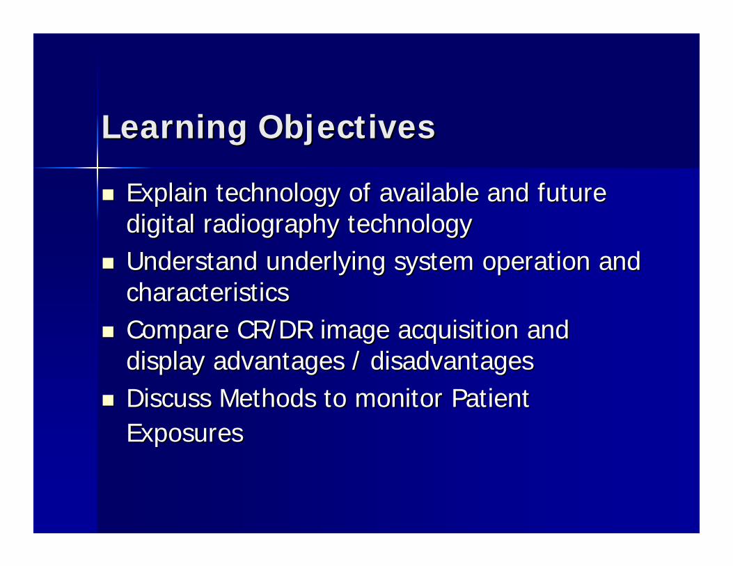
““DigitalDigital””RadiologyRadiology
MRIMRI
CTCT Nuclear MedicineNuclear Medicine UltrasoundUltrasound
Digital RadiographyDigital Radiography
Interventional Interventional AngioAngioPACSPACS
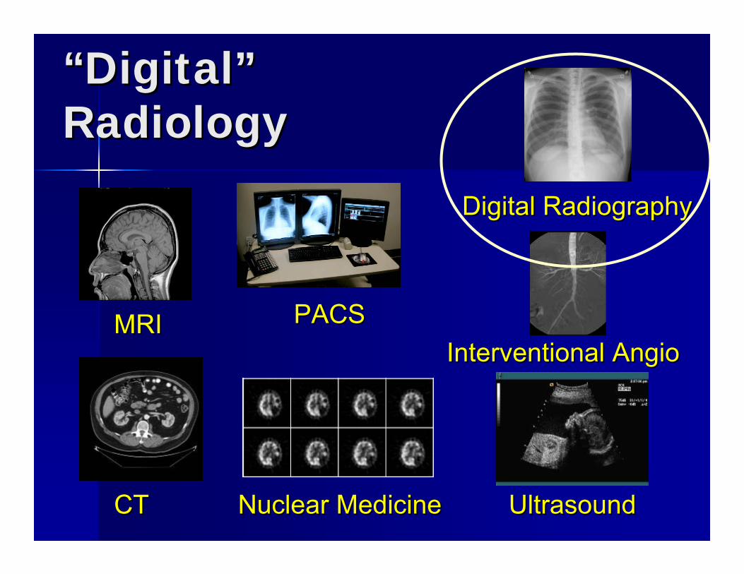
Fundamentals of Digital Fundamentals of Digital RadiographyRadiography
ScreenScreen--film radiographyfilm radiography
Analog versus digital Analog versus digital
Digital image acquisition and displayDigital image acquisition and display
Pre and post processingPre and post processing
Radiation dose issuesRadiation dose issues
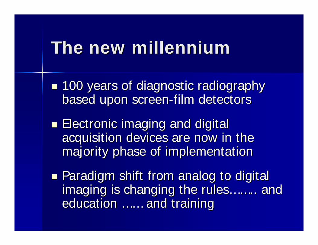
The new millenniumThe new millennium
100 years of diagnostic radiography 100 years of diagnostic radiography based upon screenbased upon screen--film detectorsfilm detectors
Electronic imaging and digital Electronic imaging and digital acquisition devices are now in the acquisition devices are now in the majority phase of implementationmajority phase of implementation
Paradigm shift from analog to digital Paradigm shift from analog to digital imaging is changing the rulesimaging is changing the rules………….. and .. and education education ………… and trainingand training
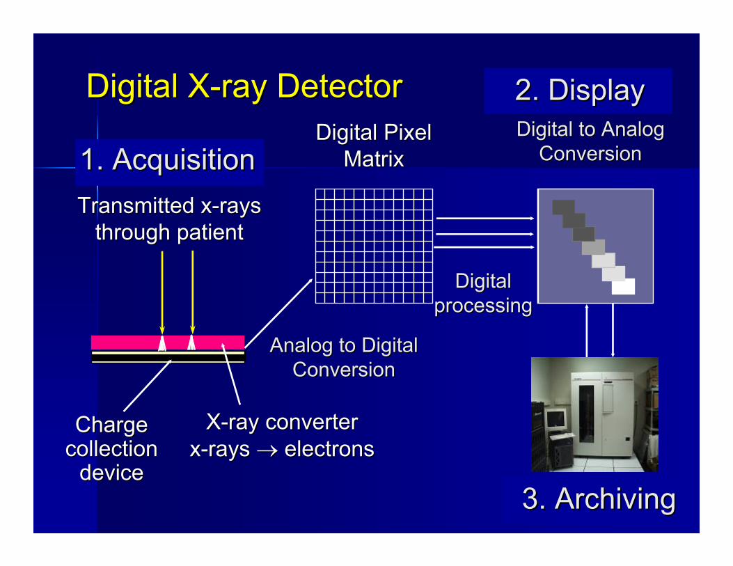
Digital XDigital X--ray Detectorray Detector
Transmitted xTransmitted x--raysraysthrough patientthrough patient
Charge Charge collection collection
devicedevice
XX--ray converterray converterxx--rays rays →→ electronselectrons
Analog to DigitalAnalog to DigitalConversionConversion
1. Acquisition1. Acquisition
2. Display2. Display
3. Archiving3. Archiving
Digital Digital processingprocessing
Digital to AnalogDigital to AnalogConversionConversion
Digital PixelDigital PixelMatrixMatrix
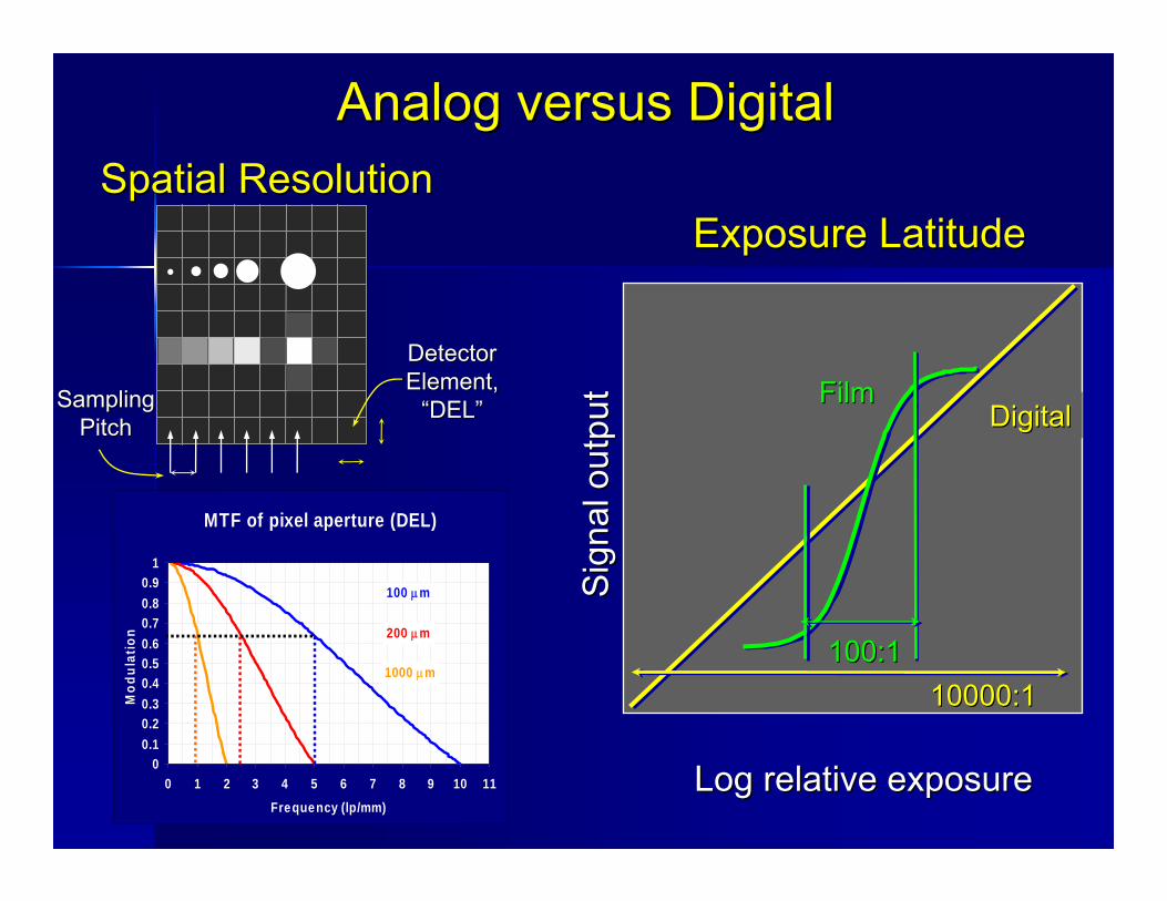
Exposure LatitudeExposure Latitude
Log relative exposureLog relative exposure
Sig
nal o
utpu
tS
igna
l out
put
10000:110000:1
DigitalDigital
Spatial ResolutionSpatial Resolution
Analog versus DigitalAnalog versus Digital
MTF of pixel aperture (DEL)
00.10.20.30.40.50.60.70.80.9
1
0 1 2 3 4 5 6 7 8 9 10 11Frequency (lp/mm)
Mod
ulat
ion
1000 μm
200 μm
100 μm
DetectorDetectorElement,Element,
““DELDEL””SamplingSamplingPitchPitch
FilmFilm
100:1100:1
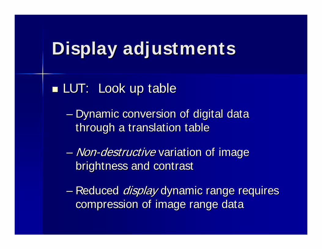
Display adjustmentsDisplay adjustments
LUT: Look up tableLUT: Look up table
–– Dynamic conversion of digital data Dynamic conversion of digital data through a translation tablethrough a translation table
–– NonNon--destructivedestructive variation of image variation of image brightness and contrastbrightness and contrast
–– Reduced Reduced displaydisplay dynamic range requires dynamic range requires compression of image range datacompression of image range data
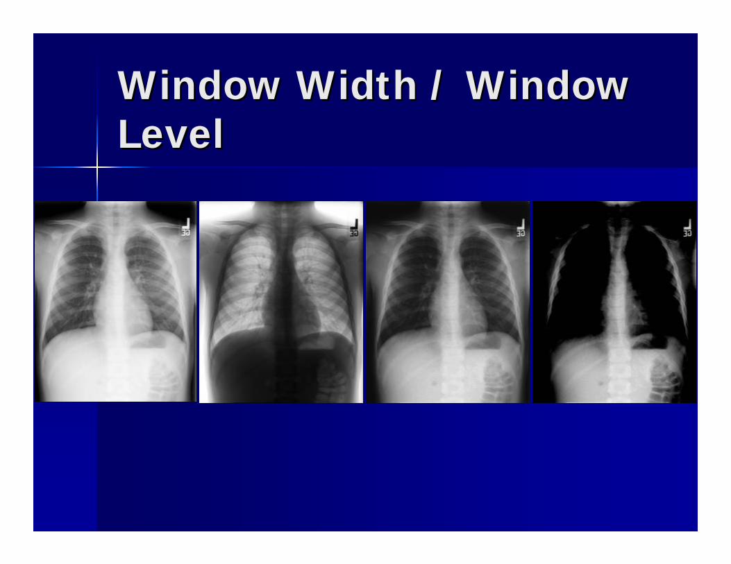
Window Width / Window Window Width / Window LevelLevel
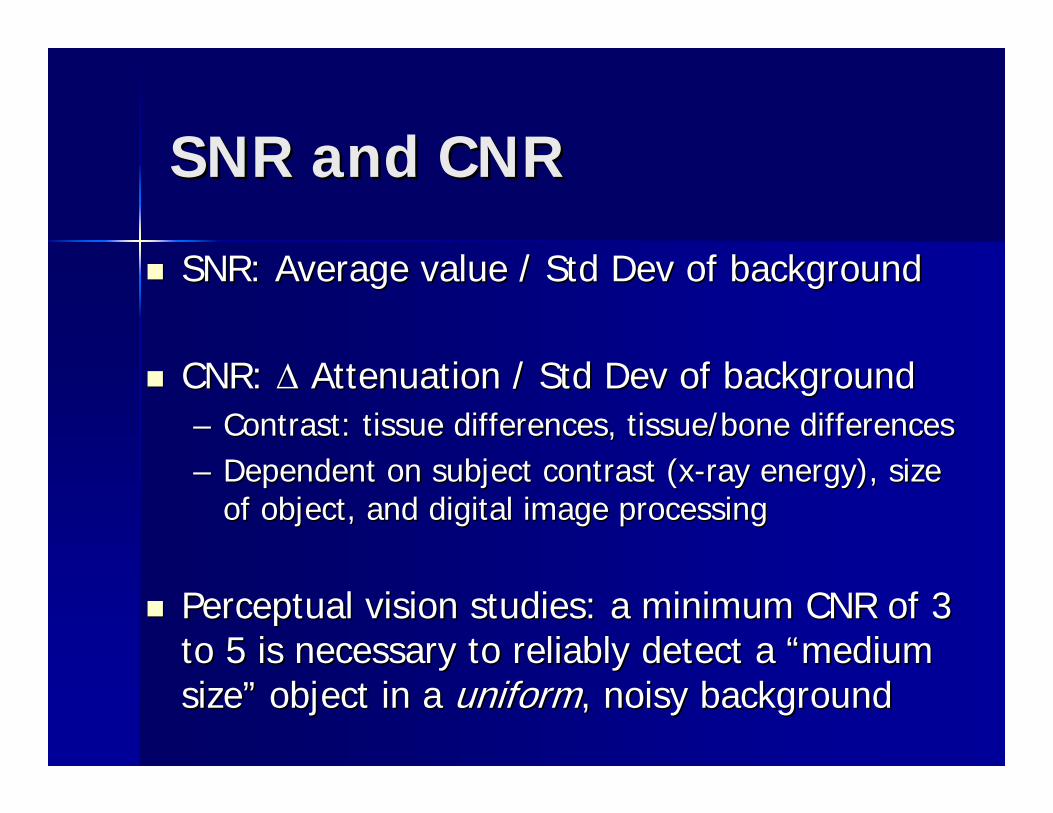
SNR and CNRSNR and CNR
SNR: Average value / Std Dev of backgroundSNR: Average value / Std Dev of background
CNR: CNR: ΔΔ Attenuation / Std Dev of backgroundAttenuation / Std Dev of background–– Contrast: tissue differences, tissue/bone differencesContrast: tissue differences, tissue/bone differences–– Dependent on subject contrast (xDependent on subject contrast (x--ray energy), size ray energy), size
of object, and digital image processingof object, and digital image processing
Perceptual vision studies: a minimum CNR of 3 Perceptual vision studies: a minimum CNR of 3 to 5 is necessary to reliably detect a to 5 is necessary to reliably detect a ““medium medium sizesize”” object in a object in a uniformuniform, noisy background, noisy background
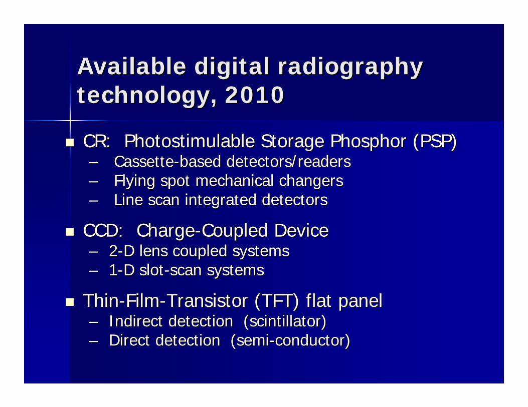
Available digital radiography Available digital radiography technology, 2010technology, 2010
CR: Photostimulable Storage Phosphor (PSP)CR: Photostimulable Storage Phosphor (PSP)–– CassetteCassette--based detectors/readersbased detectors/readers–– Flying spot mechanical changersFlying spot mechanical changers–– Line scan integrated detectorsLine scan integrated detectors
CCD: ChargeCCD: Charge--Coupled DeviceCoupled Device–– 22--D lens coupled systemsD lens coupled systems–– 11--D slotD slot--scan systemsscan systems
ThinThin--FilmFilm--Transistor (TFT) flat panelTransistor (TFT) flat panel–– Indirect detection (scintillator)Indirect detection (scintillator)–– Direct detection (semiDirect detection (semi--conductor)conductor)
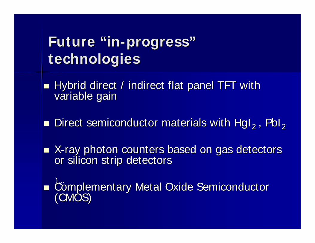
Future Future ““inin--progressprogress””technologiestechnologies
Hybrid direct / indirect flat panel TFT with Hybrid direct / indirect flat panel TFT with variable gainvariable gain
Direct semiconductor materials with HgIDirect semiconductor materials with HgI2 2 , PbI, PbI22
XX--ray photon counters based on gas detectors ray photon counters based on gas detectors or silicon strip detectorsor silicon strip detectors
Complementary Metal Oxide Semiconductor Complementary Metal Oxide Semiconductor (CMOS)(CMOS)
)...)...
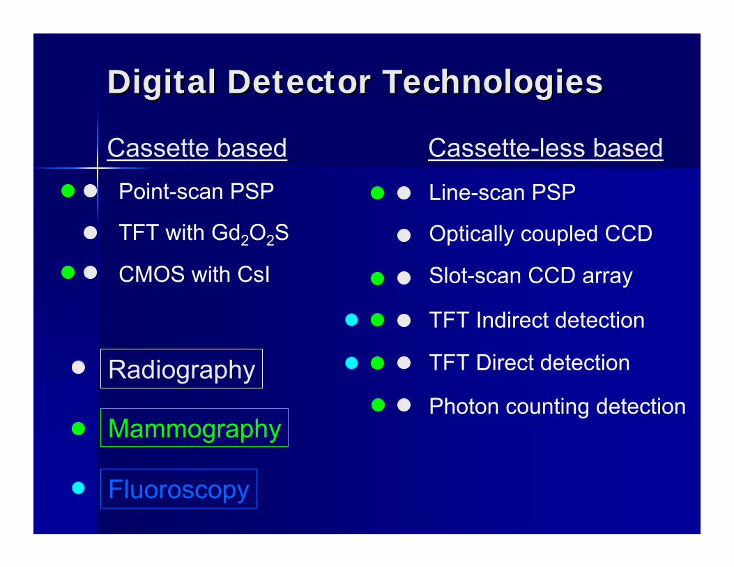
Digital Detector TechnologiesDigital Detector Technologies
Cassette based Cassette-less basedPoint-scan PSP
TFT with Gd2O2S
CMOS with CsI
Line-scan PSP
Optically coupled CCD
Slot-scan CCD array
TFT Indirect detection
TFT Direct detection
Photon counting detectionRadiography
Fluoroscopy
Mammography
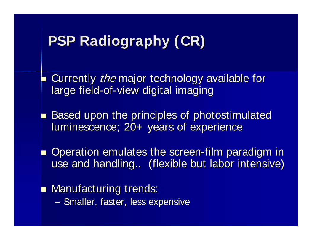
PSP Radiography (CR)PSP Radiography (CR)
Currently Currently thethe major technology available for major technology available for large fieldlarge field--ofof--view digital imagingview digital imaging
Based upon the principles of photostimulated Based upon the principles of photostimulated luminescence; 20+ years of experienceluminescence; 20+ years of experience
Operation emulates the screenOperation emulates the screen--film paradigm in film paradigm in use and handling.. (flexible but labor intensive)use and handling.. (flexible but labor intensive)
Manufacturing trends: Manufacturing trends: –– Smaller, faster, less expensiveSmaller, faster, less expensive
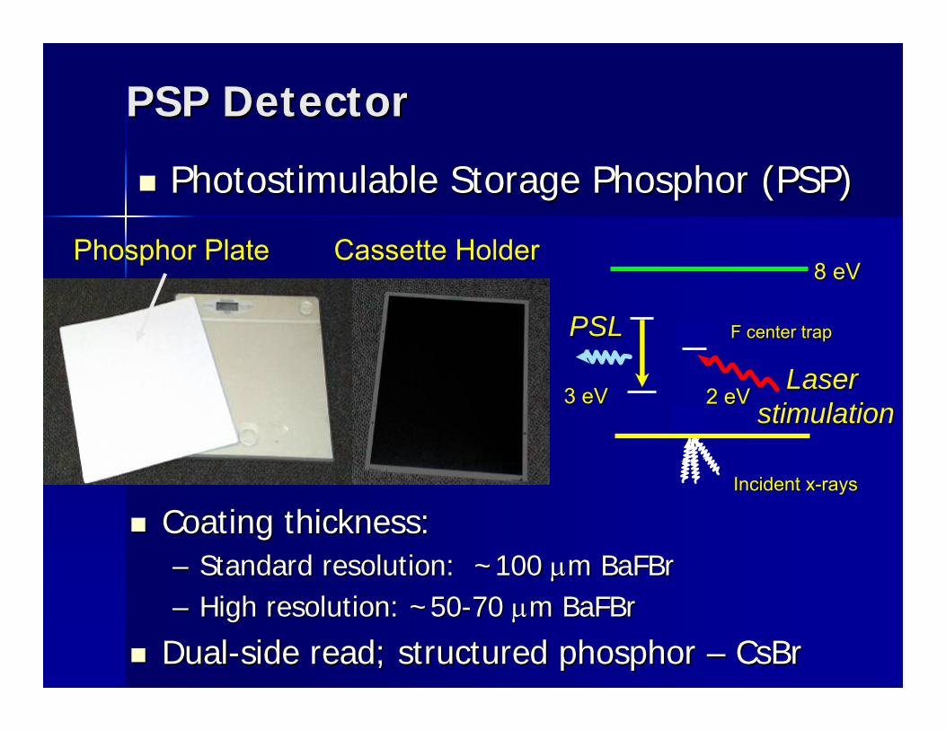
PSP DetectorPSP Detector
Photostimulable Storage Phosphor (PSP)Photostimulable Storage Phosphor (PSP)
Phosphor PlatePhosphor PlatePhosphor Plate Cassette HolderCassette HolderCassette Holder
Coating thickness:Coating thickness:–– Standard resolution: ~100 Standard resolution: ~100 μμm m BaFBrBaFBr–– High resolution: ~50High resolution: ~50--70 70 μμm m BaFBrBaFBr
DualDual--side read; structured phosphor side read; structured phosphor –– CsBrCsBr
Laser Laser stimulationstimulation2 eV2 eV
ee
Incident xIncident x--rays rays
8 eV8 eV
F center trapF center trapee--PSLPSL
3 eV3 eVeeeeee
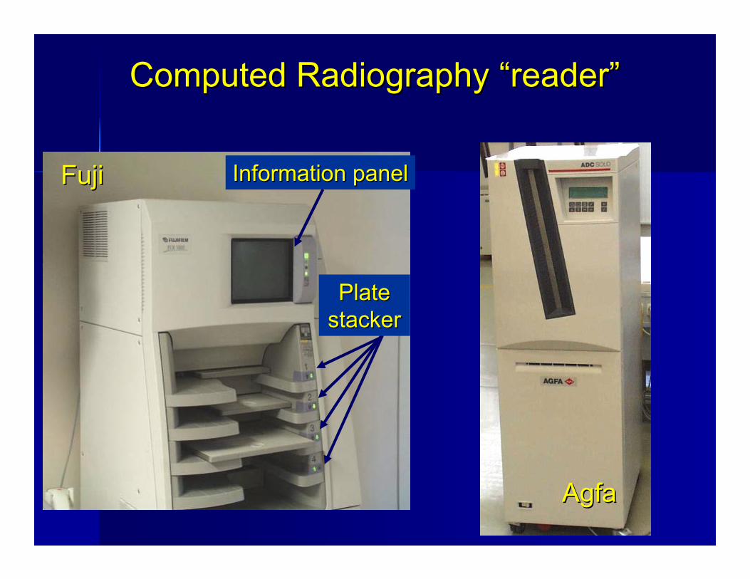
Computed Radiography Computed Radiography ““readerreader””
Information panelInformation panel
Plate Plate stackerstacker
FujiFuji
AgfaAgfa
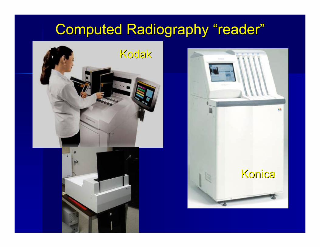
Computed Radiography Computed Radiography ““readerreader””KodakKodak
KonicaKonica
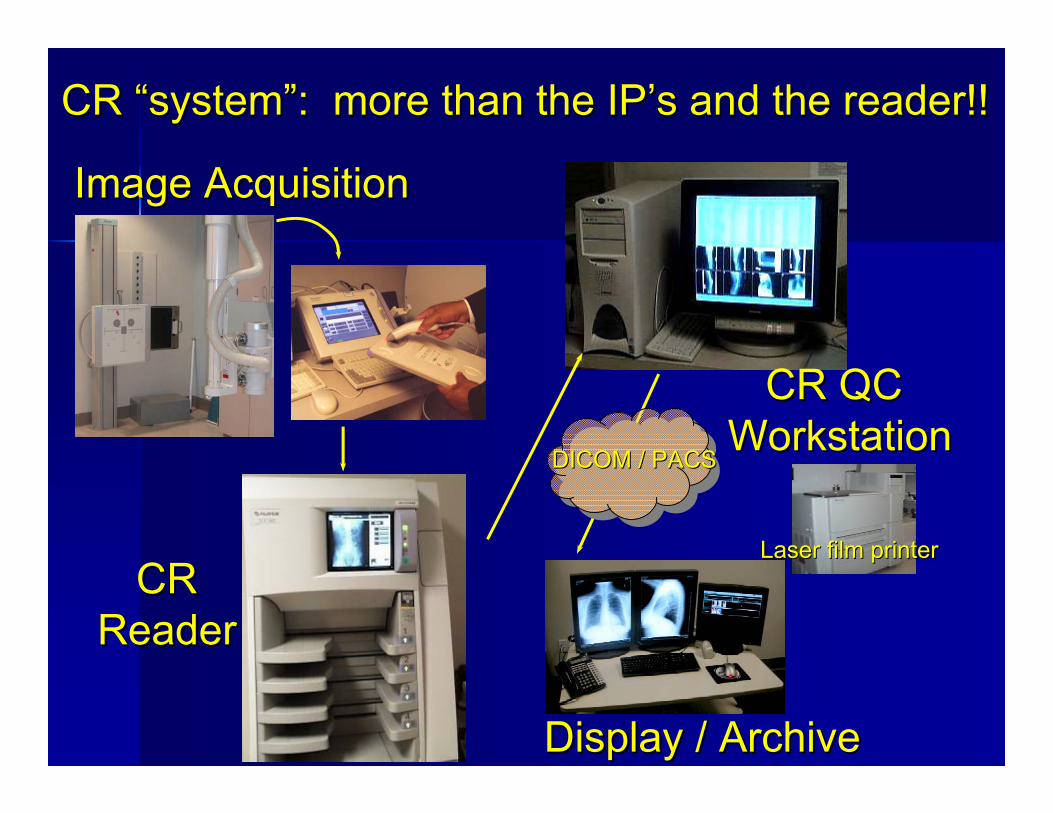
CRCRReaderReader
CR QC CR QC WorkstationWorkstation
Display / ArchiveDisplay / Archive
Laser film printerLaser film printer
DICOM / PACSDICOM / PACS
Image AcquisitionImage Acquisition
CR CR ““systemsystem””: more than the IP: more than the IP’’s and the reader!!s and the reader!!
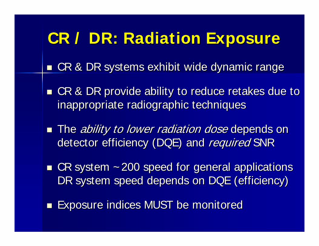
CR / DR: Radiation ExposureCR / DR: Radiation Exposure
CR & DR systems exhibit wide dynamic rangeCR & DR systems exhibit wide dynamic range
CR & DR provide ability to reduce retakes due to CR & DR provide ability to reduce retakes due to inappropriate radiographic techniquesinappropriate radiographic techniques
The The ability to lower radiation doseability to lower radiation dose depends on depends on detector efficiency (DQE) and detector efficiency (DQE) and requiredrequired SNRSNR
CR system ~200 speed for general applicationsCR system ~200 speed for general applicationsDR system speed depends on DQE (efficiency)DR system speed depends on DQE (efficiency)
Exposure indices MUST be monitoredExposure indices MUST be monitored
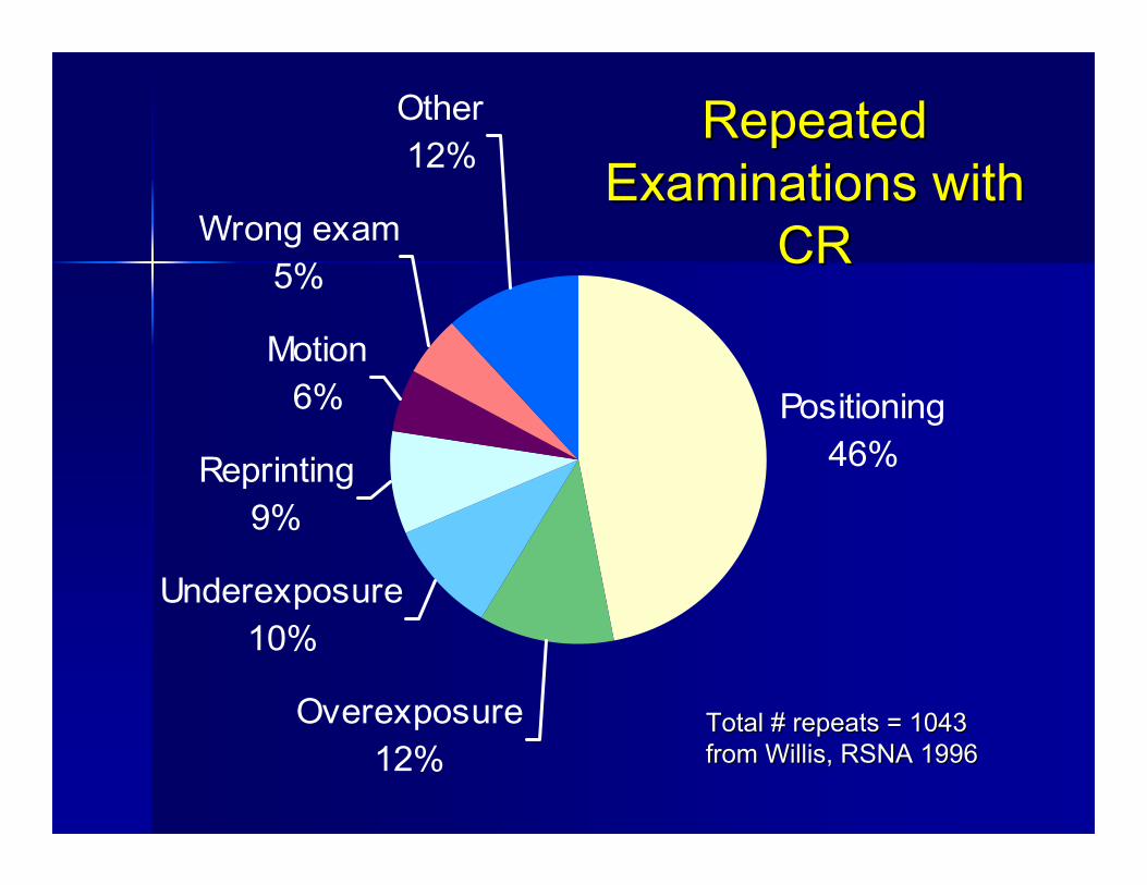
Total # repeats = 1043 Total # repeats = 1043 from Willis, RSNA 1996from Willis, RSNA 1996
Positioning46%
Overexposure12%
Underexposure10%
Reprinting9%
Motion6%
Wrong exam5%
Other12%
Repeated Repeated Examinations with Examinations with
CRCR
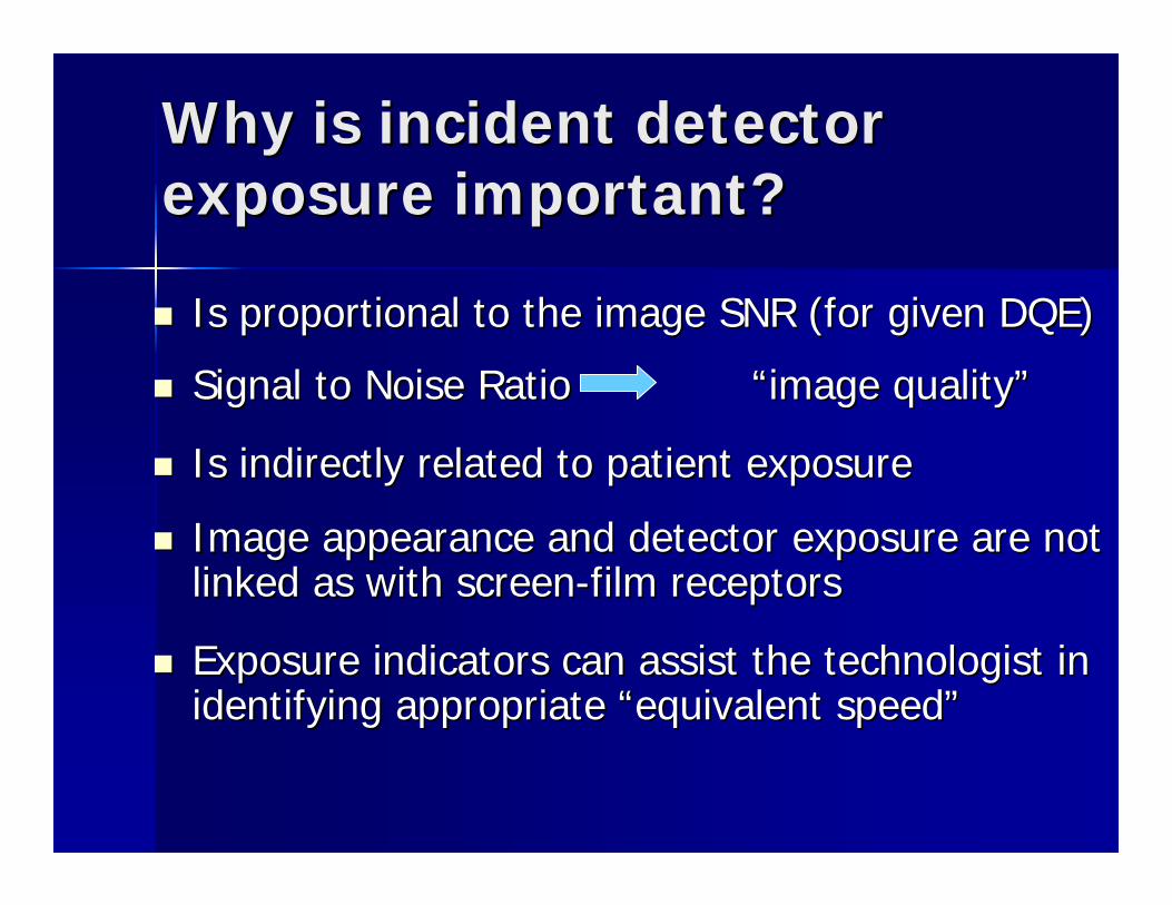
Why is incident detector Why is incident detector exposure important? exposure important?
Is proportional to the image SNR (for given DQE)Is proportional to the image SNR (for given DQE)
Signal to Noise Ratio Signal to Noise Ratio ““image qualityimage quality””
Is indirectly related to patient exposure Is indirectly related to patient exposure
Image appearance and detector exposure are not Image appearance and detector exposure are not linked as with screenlinked as with screen--film receptorsfilm receptors
Exposure indicators can assist the technologist in Exposure indicators can assist the technologist in identifying appropriate identifying appropriate ““equivalent speedequivalent speed””
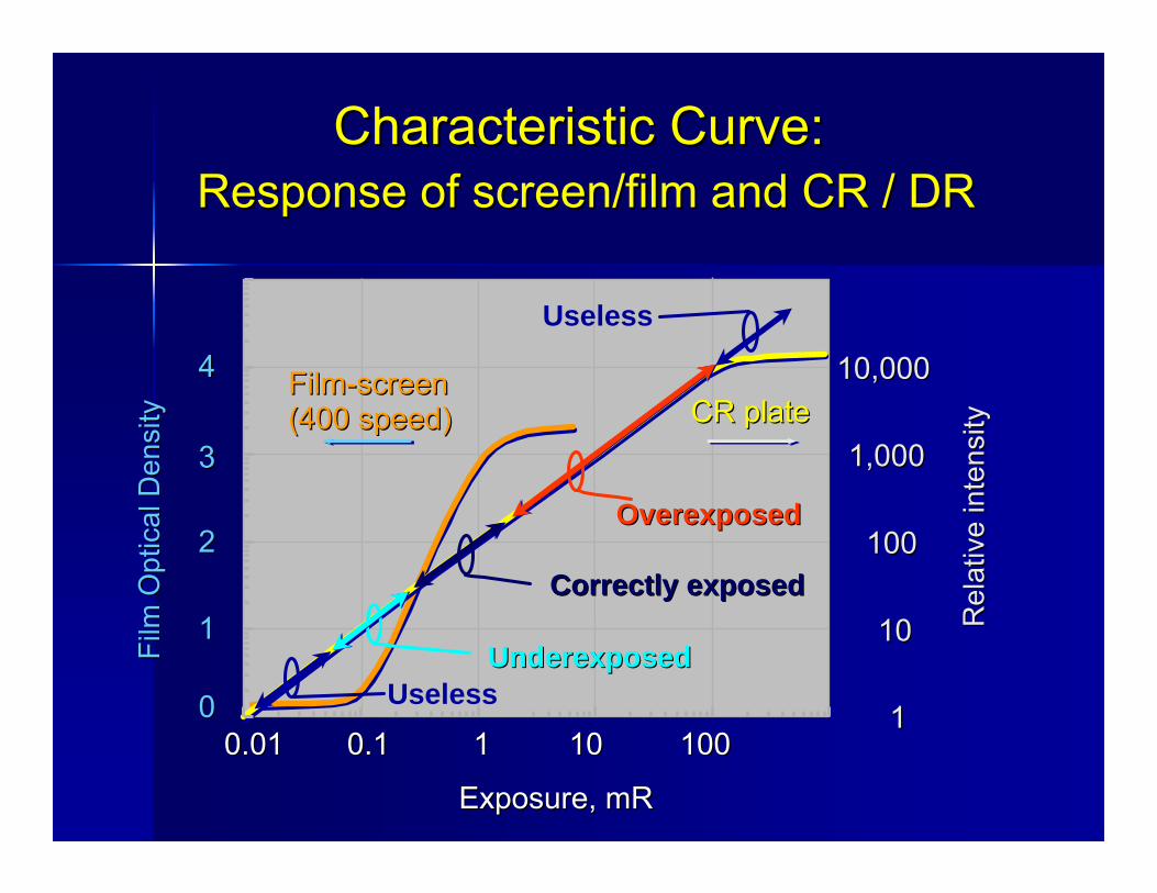
CR plateCR plateFilmFilm--screenscreen(400 speed)(400 speed)
0.010.01 0.10.1 11 1010 10010011
1010
100100
1,0001,000
10,00010,000
Exposure, mRExposure, mR
Rel
ativ
e in
tens
ityR
elat
ive
inte
nsity
Film
Opt
ical
Den
sity
Film
Opt
ical
Den
sity
00
11
22
33
44
UnderexposedUnderexposed
OverexposedOverexposed
Correctly exposedCorrectly exposed
Characteristic Curve:Characteristic Curve:Response of screen/film and CR / DRResponse of screen/film and CR / DR
Useless
Useless
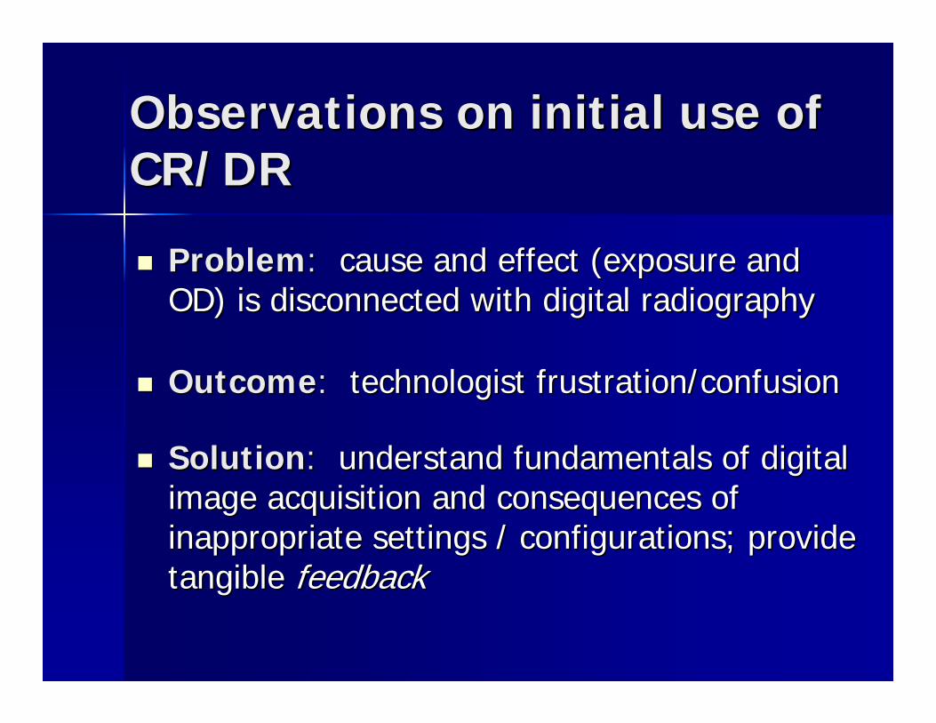
Observations on initial use of Observations on initial use of CR/DRCR/DR
ProblemProblem:: cause and effect (exposure and cause and effect (exposure and OD) is disconnected with digital radiographyOD) is disconnected with digital radiography
OutcomeOutcome:: technologist frustration/confusiontechnologist frustration/confusion
SolutionSolution:: understand fundamentals of digital understand fundamentals of digital image acquisition and consequences of image acquisition and consequences of inappropriate settings / configurations; provide inappropriate settings / configurations; provide tangible tangible feedbackfeedback
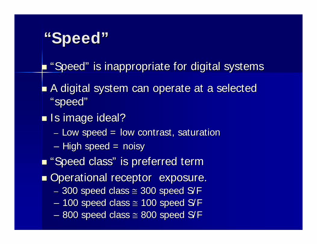
““SpeedSpeed””
““SpeedSpeed”” is inappropriate for digital systemsis inappropriate for digital systems
A digital system can operate at a selected A digital system can operate at a selected ““speedspeed””Is image ideal?Is image ideal?–– Low speed = low contrast, saturationLow speed = low contrast, saturation–– High speed = noisyHigh speed = noisy
““Speed classSpeed class”” is preferred termis preferred termOperational receptor exposure.Operational receptor exposure.–– 300 speed class 300 speed class ≅≅ 300 speed S/F300 speed S/F–– 100 speed class 100 speed class ≅≅ 100 speed S/F100 speed S/F–– 800 speed class 800 speed class ≅≅ 800 speed S/F800 speed S/F
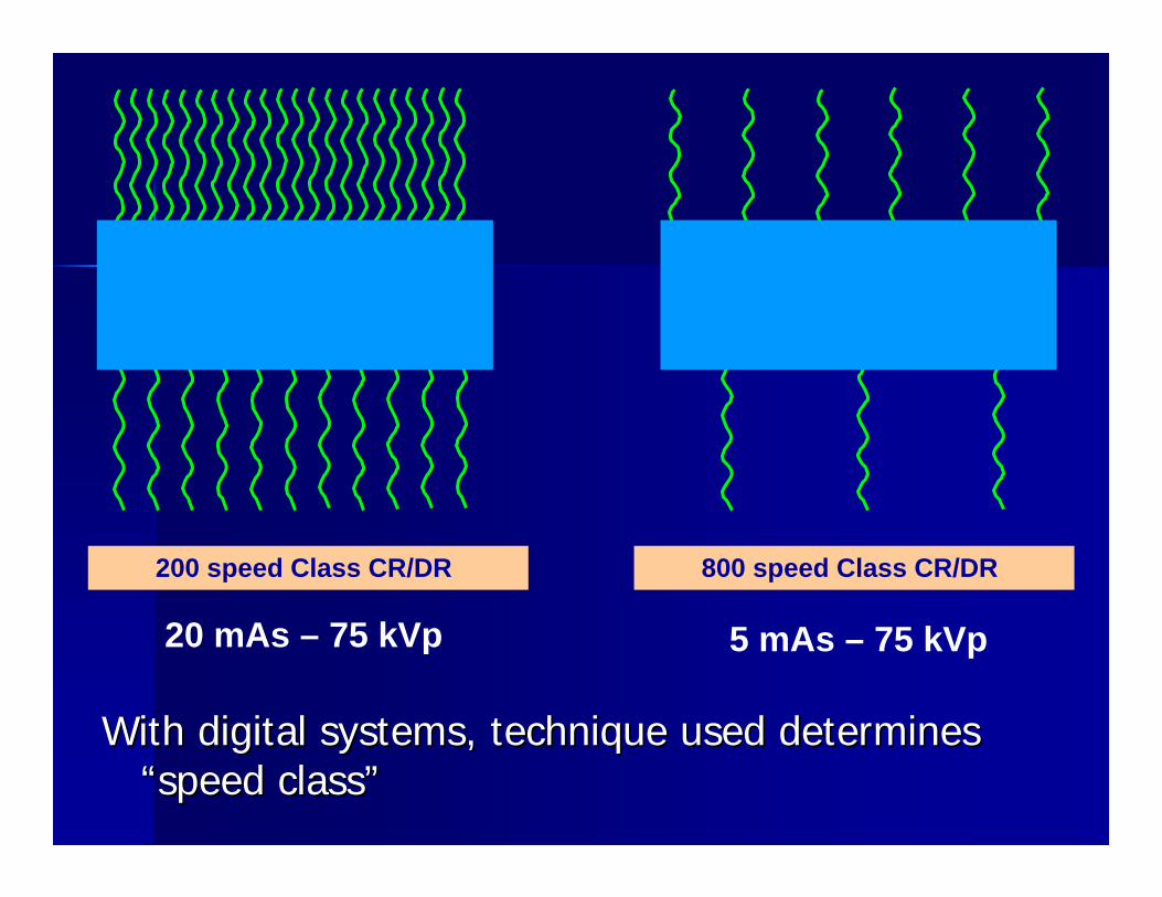
200 speed Class CR/DR 800 speed Class CR/DR
20 mAs – 75 kVp 5 mAs – 75 kVp
With digital systems, tWith digital systems, technique used determines echnique used determines ““speed classspeed class””
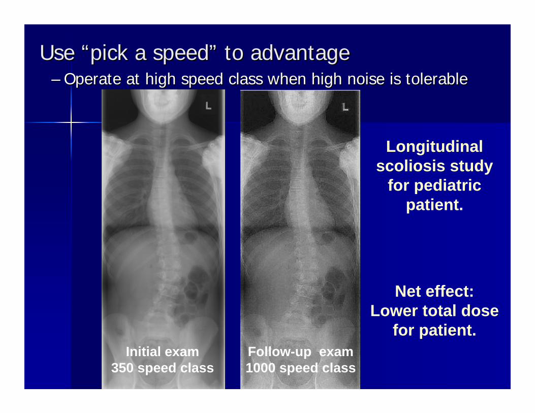
Use Use ““pick a speedpick a speed”” to advantageto advantage–– Operate at high speed class when Operate at high speed class when high noise is tolerablehigh noise is tolerable
Initial exam350 speed class
Follow-up exam1000 speed class
Net effect:Lower total dose
for patient.
Longitudinal scoliosis study
for pediatric patient.
How low can you go?How low can you go?
Dependent on the needed image Dependent on the needed image fidelityfidelity
Determined by the detector efficiencyDetermined by the detector efficiency
Detailed by the system exposure index Detailed by the system exposure index
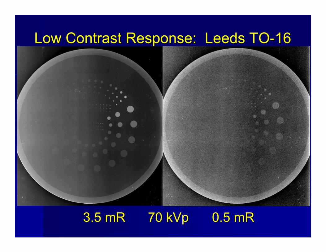
Low Contrast Response: Leeds TOLow Contrast Response: Leeds TO--1616
0.5 mR0.5 mR3.5 mR3.5 mR 70 kVp70 kVp
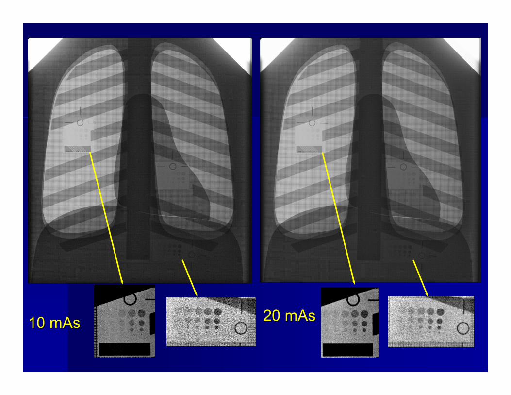
10 mAs10 mAs 20 mAs20 mAs
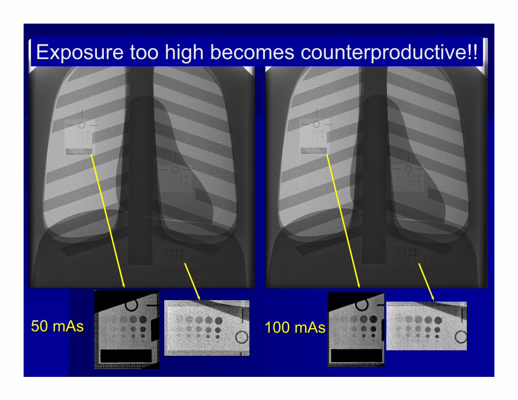
50 mAs50 mAs 100 mAs100 mAs
Exposure too high becomes counterproductive!!
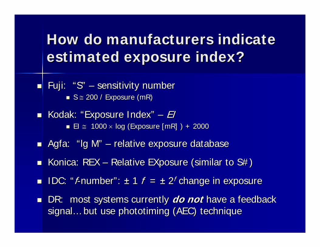
How do manufacturers indicate How do manufacturers indicate estimated exposure index?estimated exposure index?
Fuji: Fuji: ““SS”” –– sensitivity numbersensitivity numberS S ≅≅ 200 / Exposure (mR)200 / Exposure (mR)
Kodak: Kodak: ““Exposure IndexExposure Index”” –– EIEIEI EI ≅≅ 1000 1000 ×× log (Exposure [mR] ) + 2000 log (Exposure [mR] ) + 2000
Agfa: Agfa: ““lglg MM”” –– relative exposure databaserelative exposure database
Konica: REX Konica: REX –– Relative Relative EXposureEXposure (similar to S#)(similar to S#)
IDC: IDC: ““ff--numbernumber””: : ±± 1 1 ff = = ±± 22ff change in exposure change in exposure
DR: most systems currently DR: most systems currently do notdo not have a feedback have a feedback signalsignal…… but use phototiming (AEC) techniquebut use phototiming (AEC) technique
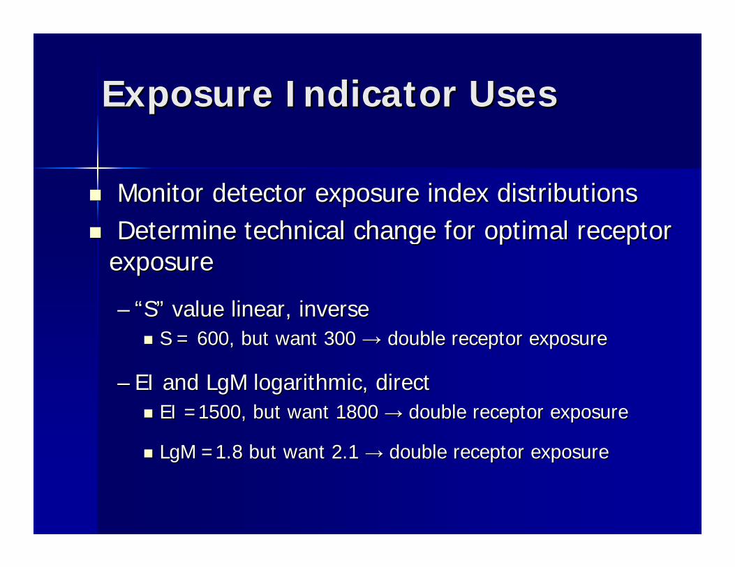
Exposure Indicator UsesExposure Indicator Uses
Monitor detector exposure index distributionsMonitor detector exposure index distributionsDetermine technical change for optimal receptor Determine technical change for optimal receptor exposureexposure
–– ““SS”” value linear, inversevalue linear, inverseS = 600, but want 300 S = 600, but want 300 →→ ddouble receptor exposureouble receptor exposure
–– EI and LgM logarithmic, directEI and LgM logarithmic, directEI =1500, but want 1800 EI =1500, but want 1800 →→ ddouble receptor exposureouble receptor exposure
LgMLgM =1.8 but want 2.1 =1.8 but want 2.1 →→ double receptor exposuredouble receptor exposure
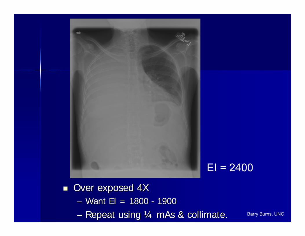
EI = 2400
Over exposed 4XOver exposed 4X–– Want EI = 1800 Want EI = 1800 -- 19001900
–– Repeat using Repeat using ¼¼ mAs & collimate.mAs & collimate. Barry Burns, UNC
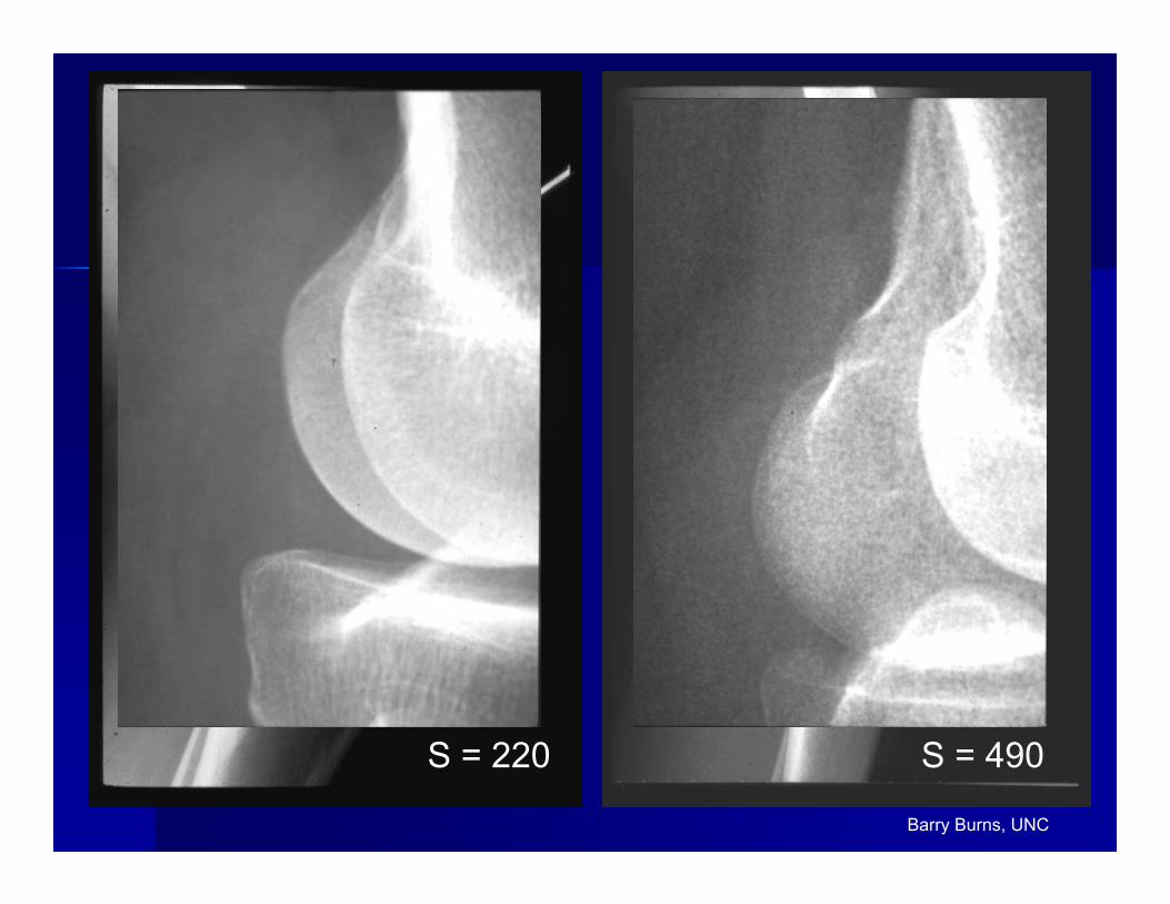
S = 220 S = 490
Barry Burns, UNC
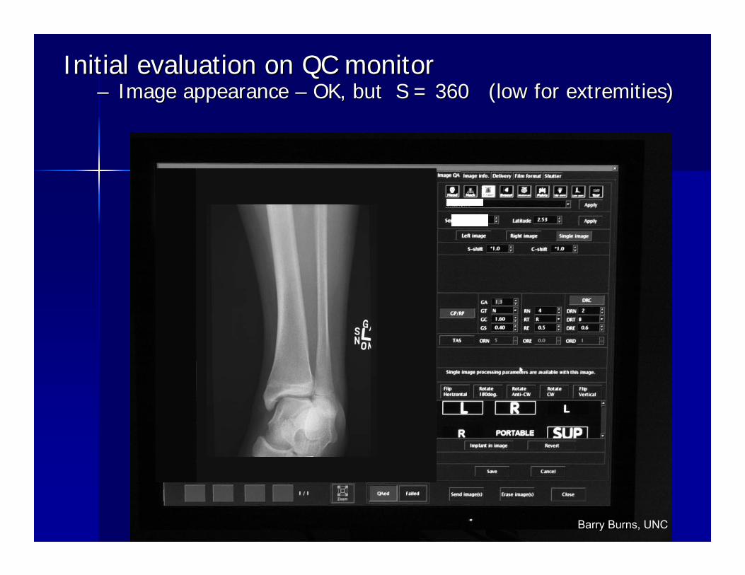
Initial evaluation on QC monitorInitial evaluation on QC monitor–– Image appearance Image appearance –– OK, but S = 360 (low for extremities)OK, but S = 360 (low for extremities)
Barry Burns, UNC
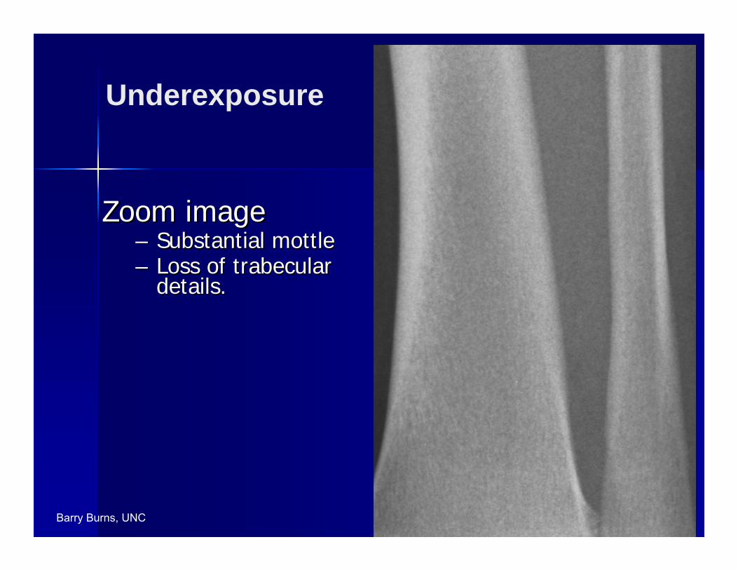
Zoom imageZoom image–– Substantial mottleSubstantial mottle–– Loss of trabecular Loss of trabecular
details.details.
Barry Burns, UNC
Underexposure
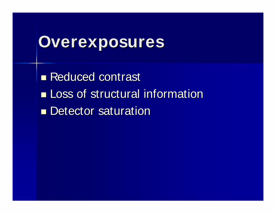
OverexposuresOverexposures
Reduced contrastReduced contrastLoss of structural informationLoss of structural informationDetector saturationDetector saturation
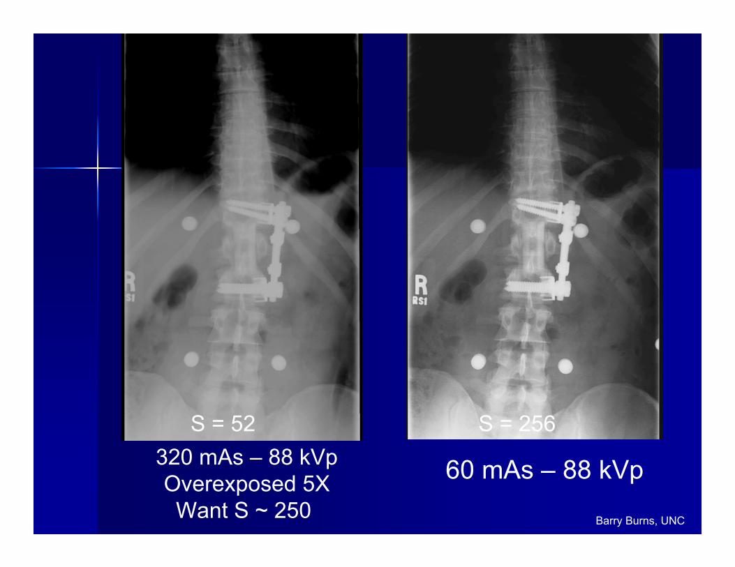
S = 52 S = 256320 mAs – 88 kVpOverexposed 5XWant S ~ 250
60 mAs – 88 kVp
Barry Burns, UNC

S = 40Over Exposed 7X Plate Saturation
Barry Burns, UNC
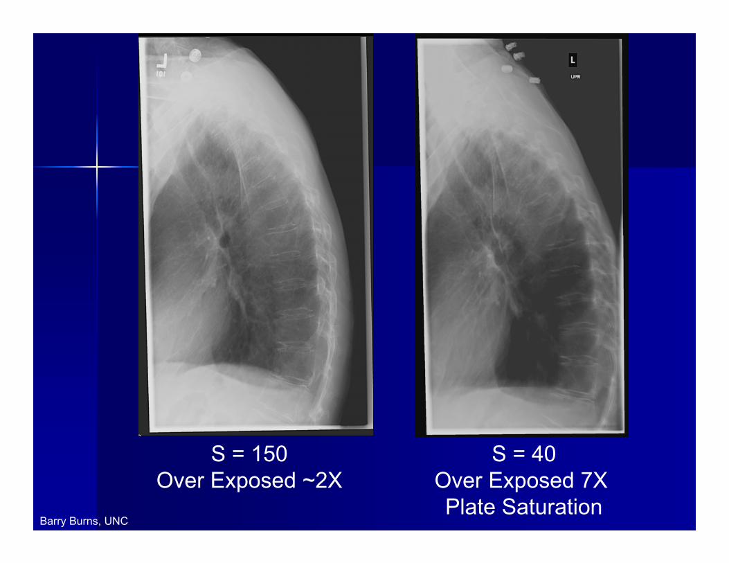
S = 40Over Exposed 7X Plate Saturation
S = 150Over Exposed ~2X
Barry Burns, UNC
Exposure with CR/DRExposure with CR/DR
Incident exposure can be Incident exposure can be ““hiddenhidden””
Low exposures have excessive image noiseLow exposures have excessive image noise
High exposures are difficult to discern and can High exposures are difficult to discern and can lead to saturation / loss of signal (over the top)lead to saturation / loss of signal (over the top)
Compensation can lead to technique Compensation can lead to technique complacency: complacency: ““just enoughjust enough”” is desiredis desired
Feedback is necessary but indices are confusing Feedback is necessary but indices are confusing and very different, depending on manufacturer! and very different, depending on manufacturer!
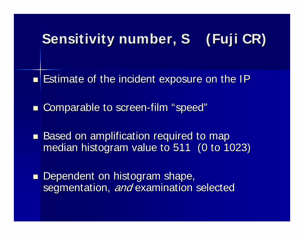
Sensitivity number, S (Fuji CR)Sensitivity number, S (Fuji CR)
Estimate of the incident exposure on the IPEstimate of the incident exposure on the IP
Comparable to screenComparable to screen--film film ““speedspeed””
Based on amplification required to map Based on amplification required to map median histogram value to 511 (0 to 1023)median histogram value to 511 (0 to 1023)
Dependent on histogram shape, Dependent on histogram shape, segmentation, segmentation, andand examination selectedexamination selected
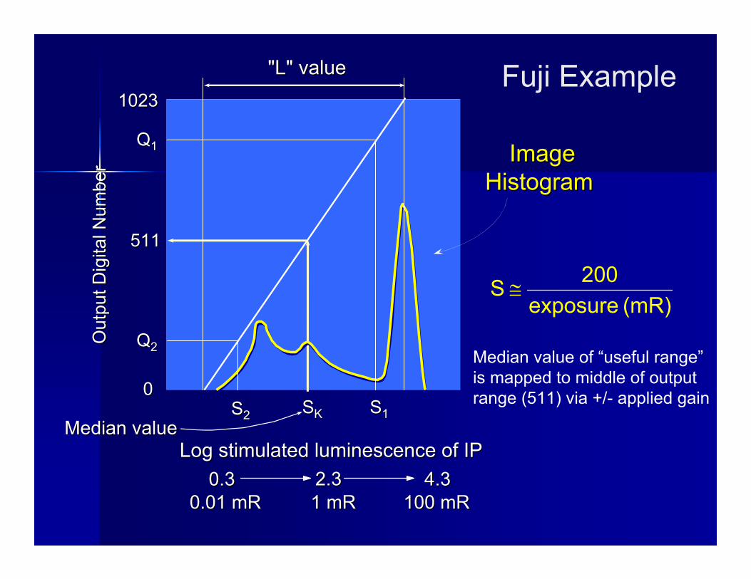
ImageImageHistogram Histogram
Median valueMedian valueLog stimulated luminescence of IPLog stimulated luminescence of IP
0.30.3 4.34.30.01 mR0.01 mR 100 mR100 mR
2.32.31 mR1 mR
(mR) exposure200 S ≅
(mR) exposure200 S ≅
Out
put D
igita
l Num
ber
Out
put D
igita
l Num
ber
00
511511
10231023
"L" value"L" value
QQ11
QQ22
SS11SS22 SSKK
Median value of “useful range”is mapped to middle of output range (511) via +/- applied gain
Fuji Example
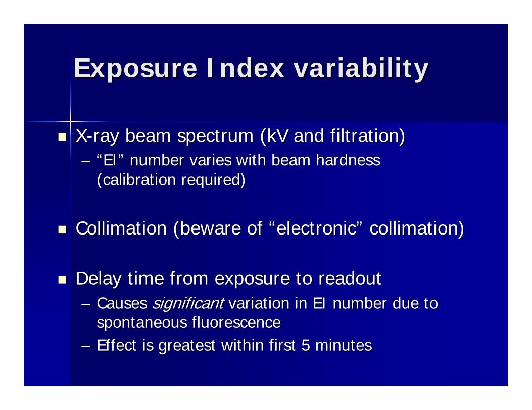
Exposure Index variabilityExposure Index variability
XX--ray beam spectrum (kV and filtration)ray beam spectrum (kV and filtration)–– ““EIEI”” number varies with beam hardness number varies with beam hardness
(calibration required)(calibration required)
Collimation (beware of Collimation (beware of ““electronicelectronic”” collimation)collimation)
Delay time from exposure to readoutDelay time from exposure to readout–– Causes Causes significantsignificant variation in EI number due to variation in EI number due to
spontaneous fluorescencespontaneous fluorescence–– Effect is greatest within first 5 minutesEffect is greatest within first 5 minutes
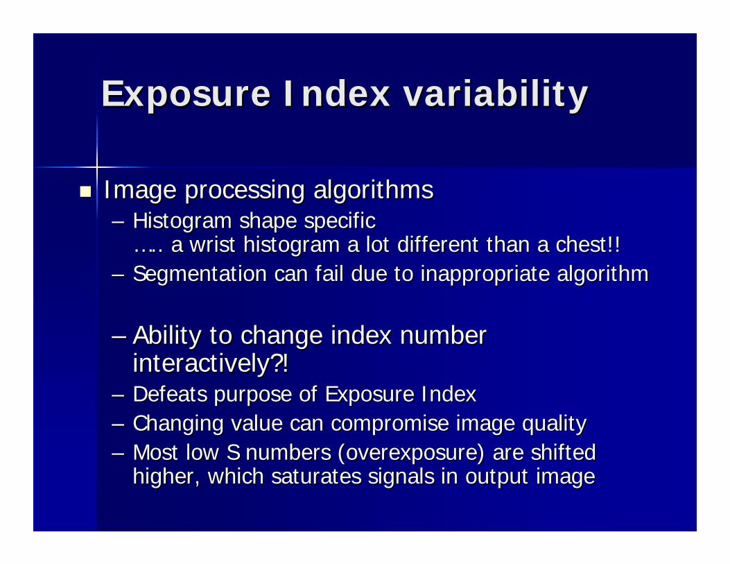
Exposure Index variabilityExposure Index variability
Image processing algorithms Image processing algorithms –– Histogram shape specific Histogram shape specific
…….. a wrist histogram a lot different than a chest!!.. a wrist histogram a lot different than a chest!!–– Segmentation can fail due to inappropriate algorithmSegmentation can fail due to inappropriate algorithm
–– Ability to change index number Ability to change index number interactively?!interactively?!
–– Defeats purpose of Exposure IndexDefeats purpose of Exposure Index–– Changing value can compromise image qualityChanging value can compromise image quality–– Most low S numbers (overexposure) are shifted Most low S numbers (overexposure) are shifted
higher, which saturates signals in output imagehigher, which saturates signals in output image
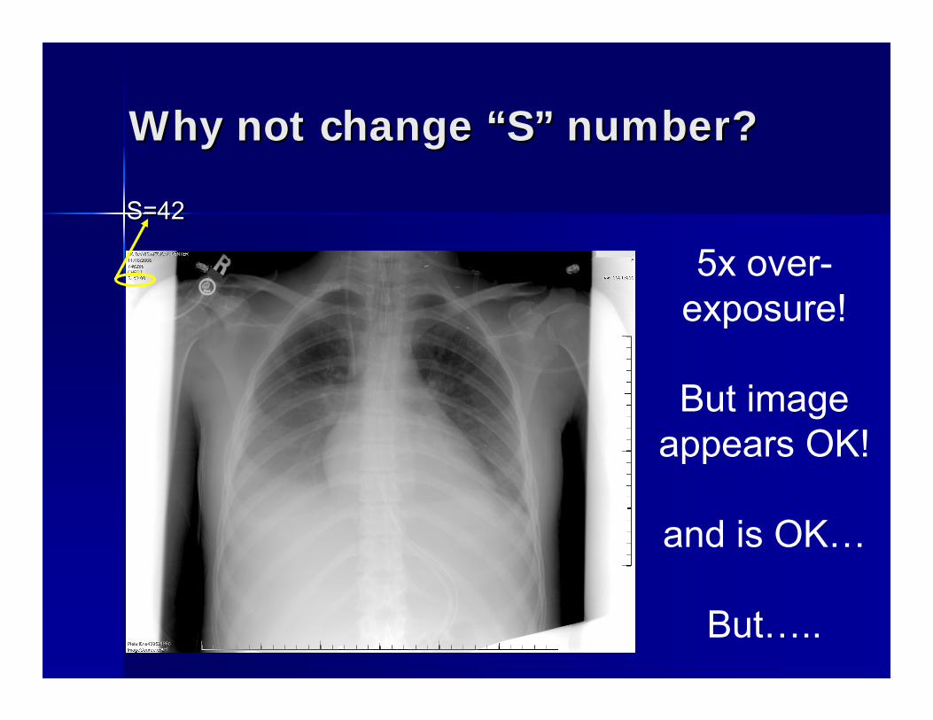
Why not change Why not change ““SS”” number?number?
S=42S=42
5x over-exposure!
But image appears OK!
and is OK…
But…..
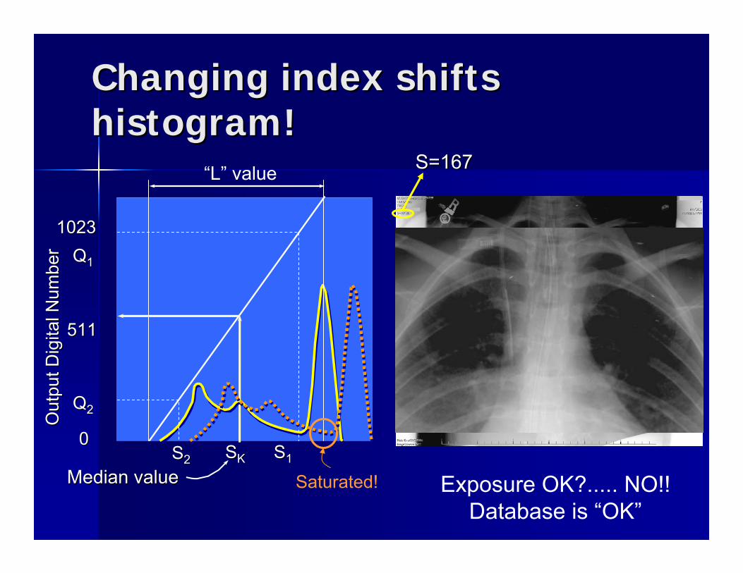
Changing index shifts Changing index shifts histogram!histogram!
Median valueMedian value
Out
put D
igita
l Num
ber
Out
put D
igita
l Num
ber
00
511511
10231023QQ11
QQ22
SS11SS22 SSKK
Saturated!
S=167S=167
Exposure OK?..... NO!!Database is “OK”
“L” value
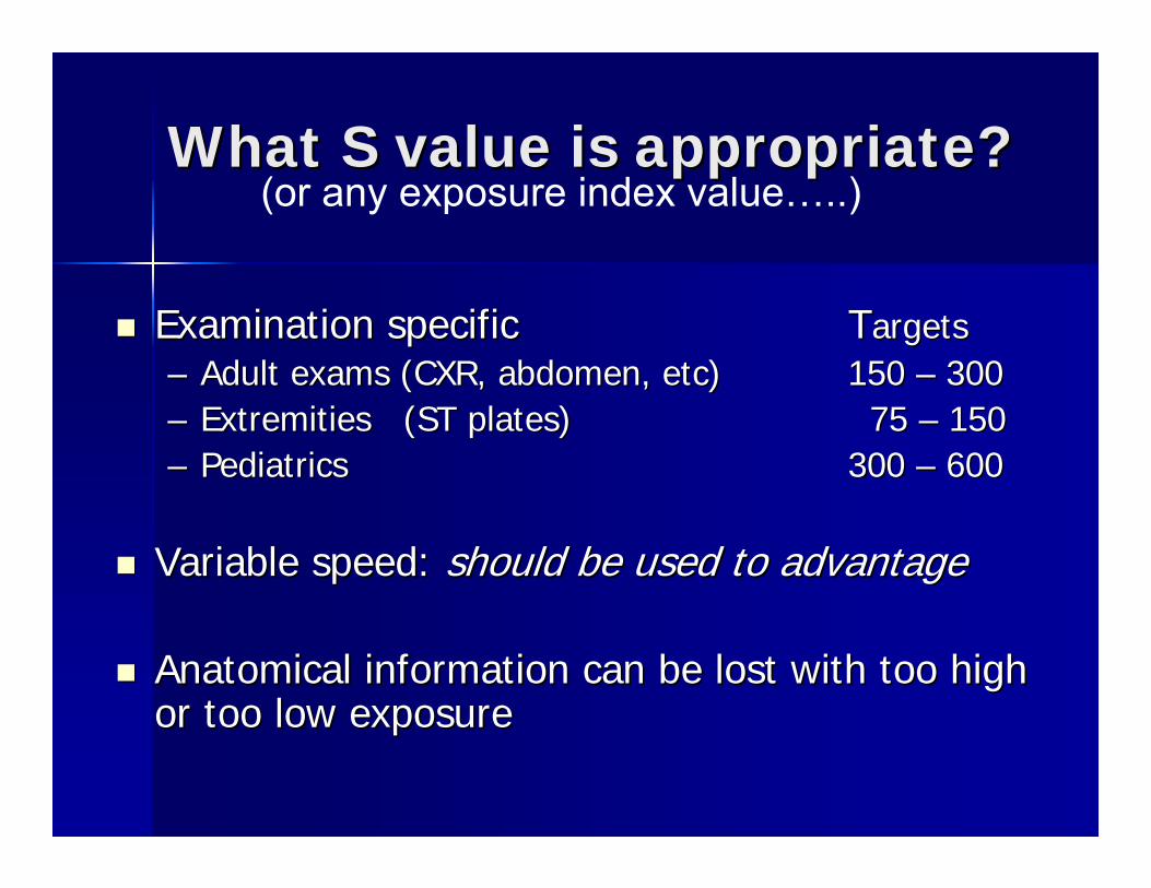
What S value is appropriate?What S value is appropriate?
Examination specificExamination specific TTargetsargets–– Adult exams (CXR, abdomen, etc) Adult exams (CXR, abdomen, etc) 150 150 –– 300300–– Extremities (ST plates) Extremities (ST plates) 75 75 –– 150150–– PediatricsPediatrics 300 300 –– 600600
Variable speed: Variable speed: should be used to advantageshould be used to advantage
Anatomical information can be lost with too high Anatomical information can be lost with too high or too low exposureor too low exposure
(or any exposure index value…..)
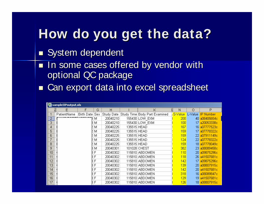
How do you get the data?How do you get the data?System dependentSystem dependentIn some cases offered by vendor with In some cases offered by vendor with optional QC packageoptional QC packageCan export data into excel spreadsheetCan export data into excel spreadsheet
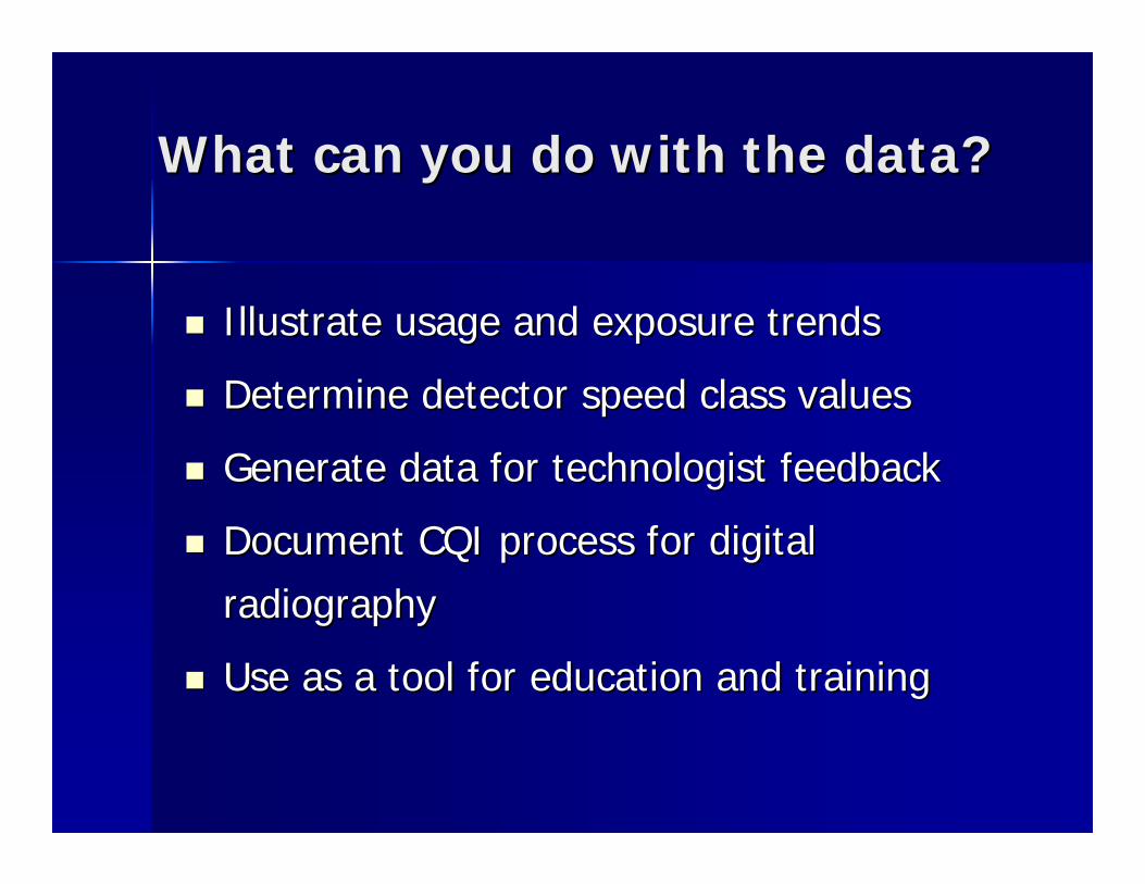
What can you do with the data?What can you do with the data?
Illustrate usage and exposure trendsIllustrate usage and exposure trends
Determine detector speed class valuesDetermine detector speed class values
Generate data for technologist feedbackGenerate data for technologist feedback
Document CQI process for digital Document CQI process for digital
radiographyradiography
Use as a tool for education and trainingUse as a tool for education and training
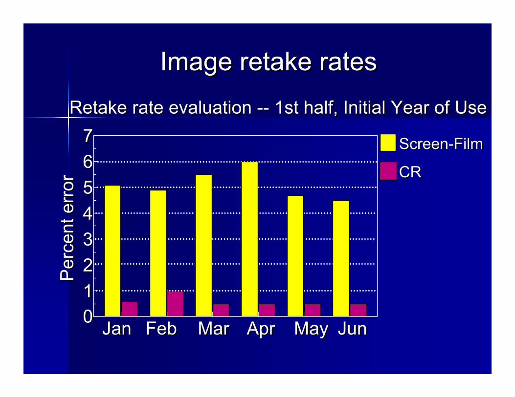
Image retake ratesImage retake rates
Retake rate evaluation Retake rate evaluation ---- 1st half, Initial Year of Use1st half, Initial Year of Use
JanJan FebFeb MarMar AprApr MayMay JunJun0011223344556677
Per
cent
err
orP
erce
nt e
rror
ScreenScreen--FilmFilm
CRCR
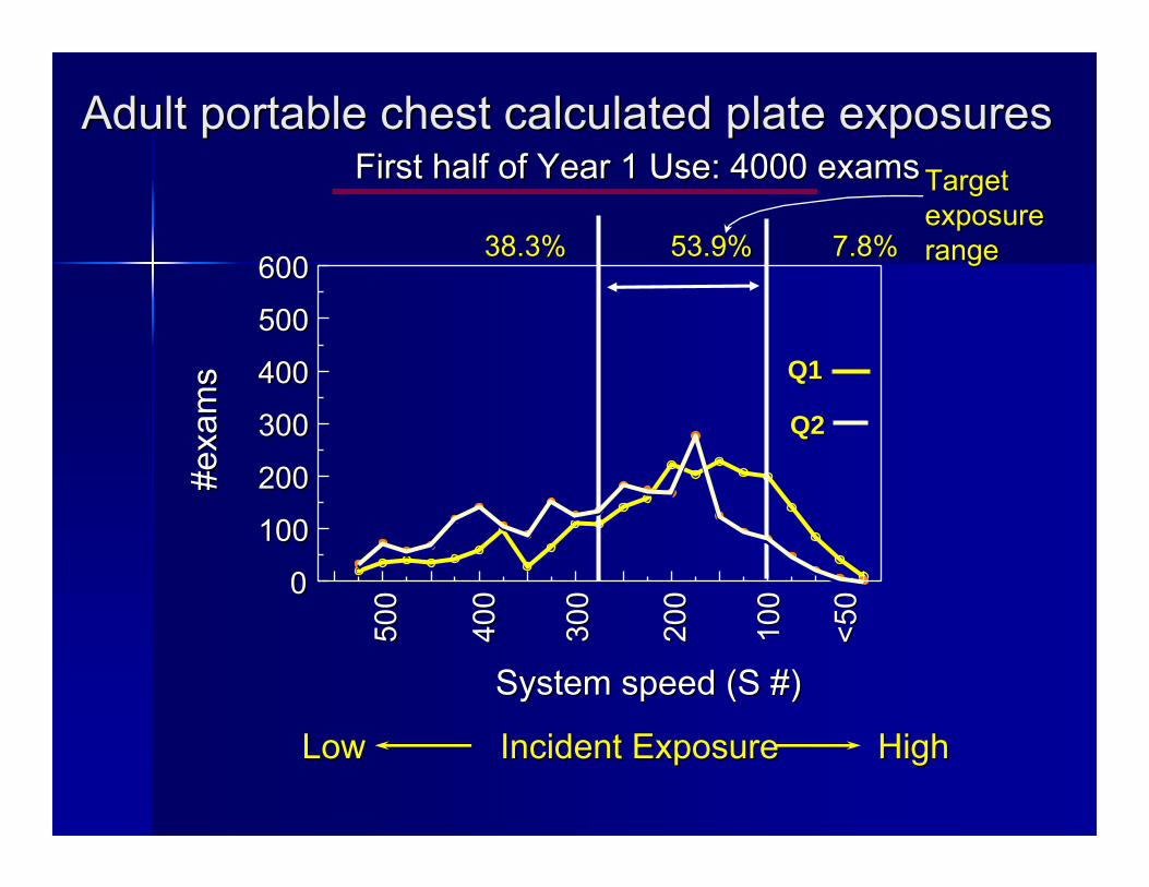
Adult portable chest calculated plate exposuresAdult portable chest calculated plate exposuresFirst half of Year 1 Use: 4000 examsFirst half of Year 1 Use: 4000 exams
Incident ExposureIncident ExposureLowLow HighHigh
500
500
400
400
300
300
200
200
100
100
<50
<5000
100100
200200
300300
400400
500500
600600
System speed (S #)System speed (S #)
#exa
ms
#exa
ms
38.3% 53.9% 7.8%38.3% 53.9% 7.8%
Target Target exposure exposure rangerange
Q1Q1
Q2Q2
Q3Q3
Q4Q4
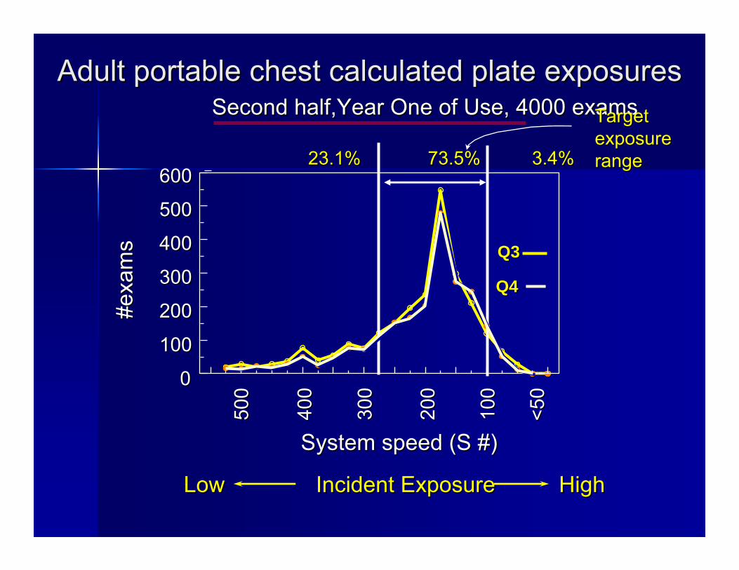
Adult portable chest calculated plate exposuresAdult portable chest calculated plate exposuresSecond Second half,Yearhalf,Year One of Use, 4000 examsOne of Use, 4000 exams
23.1% 73.5% 3.4%23.1% 73.5% 3.4%
Target Target exposure exposure rangerange
Incident ExposureIncident ExposureLowLow HighHigh
500
500
400
400
300
300
200
200
100
100
<50
<5000
100100
200200
300300
400400
500500
600600
System speed (S #)System speed (S #)
#exa
ms
#exa
ms
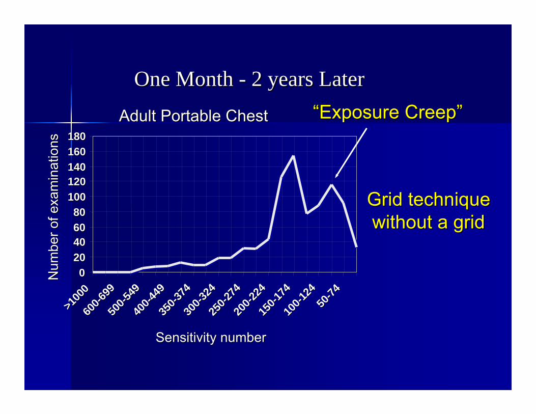
One Month One Month -- 2 years Later2 years Later
Adult Portable ChestAdult Portable Chest
002020404060608080
100100120120140140160160180180
>100
0>1
000
600
600--69
969
950
050
0--549
549
400
400--44
944
935
035
0--374
374
300
300--32
432
425
025
0--274
274
200
200--22
422
415
015
0--174
174
100
100--12
412
45050
--7474
Sensitivity numberSensitivity number
Num
ber o
f exa
min
atio
nsN
umbe
r of e
xam
inat
ions
““Exposure CreepExposure Creep””
Grid techniqueGrid techniquewithout a gridwithout a grid
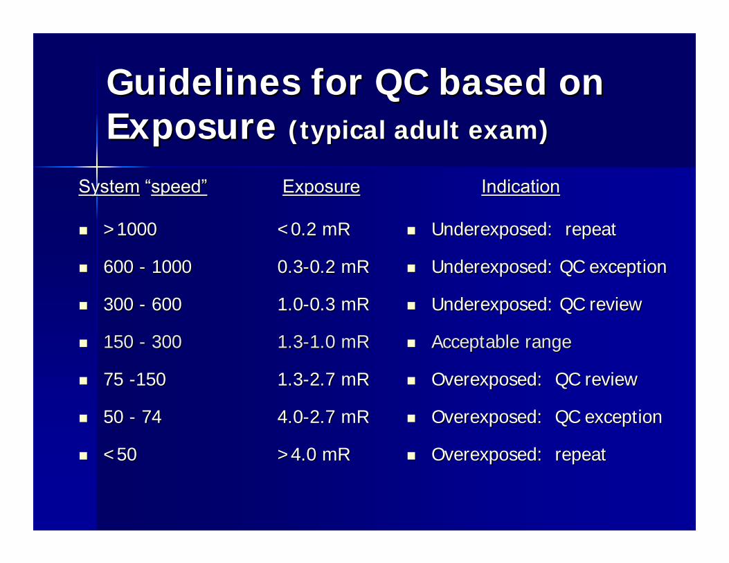
Guidelines for QC based on Guidelines for QC based on Exposure Exposure (typical adult exam)(typical adult exam)
>1000>1000 <0.2 mR<0.2 mR
600 600 -- 10001000 0.30.3--0.2 mR0.2 mR
300 300 -- 600600 1.01.0--0.3 mR0.3 mR
150 150 -- 300300 1.31.3--1.0 mR1.0 mR
75 75 --150150 1.31.3--2.7 mR2.7 mR
50 50 -- 7474 4.04.0--2.7 mR2.7 mR
<50<50 >4.0 mR>4.0 mR
Underexposed: repeatUnderexposed: repeat
Underexposed: QC exceptionUnderexposed: QC exception
Underexposed: QC reviewUnderexposed: QC review
Acceptable rangeAcceptable range
Overexposed: QC reviewOverexposed: QC review
Overexposed: QC exceptionOverexposed: QC exception
Overexposed: repeatOverexposed: repeat
SystemSystem ““speedspeed”” ExposureExposure IndicationIndication
What the exposure index doesnWhat the exposure index doesn’’t t directly tell youdirectly tell you…………
Patient dosePatient dose–– Dose is dependent on patient size, Dose is dependent on patient size,
attenuation properties, technique & setupattenuation properties, technique & setup
Image qualityImage quality–– Quality is mainly based upon SNR and Quality is mainly based upon SNR and
patient positioning; a target exposure patient positioning; a target exposure index value index value does not guarantee IQdoes not guarantee IQ
Detector exposure index: Detector exposure index: DoDo’’s and Dons and Don’’tsts
Do a periodic review of exposure logsDo a periodic review of exposure logs
Do look for outliers and repeat offendersDo look for outliers and repeat offenders
Do use as a feedback toolDo use as a feedback tool
Do ensure proper detector/reader calibrationDo ensure proper detector/reader calibration
Do NOTDo NOT place too much importance on valueplace too much importance on value
Do NOTDo NOT allow arbitrary value adjustmentallow arbitrary value adjustment
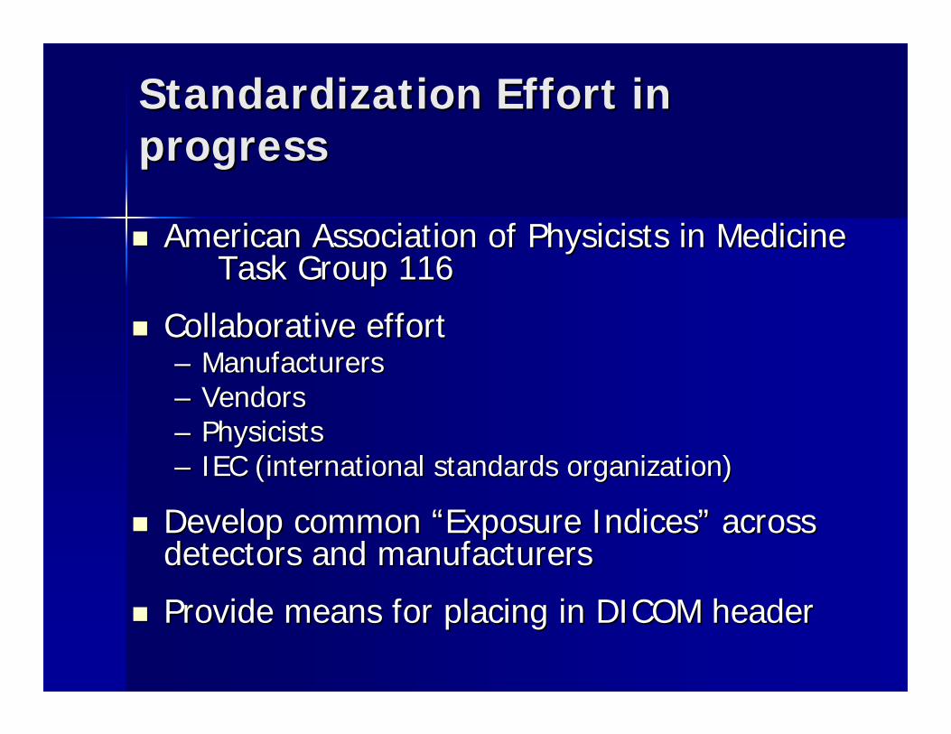
Standardization Effort in Standardization Effort in progressprogress
American Association of Physicists in Medicine American Association of Physicists in Medicine Task Group 116Task Group 116
Collaborative effortCollaborative effort–– ManufacturersManufacturers–– VendorsVendors–– PhysicistsPhysicists–– IEC (international standards organization)IEC (international standards organization)
Develop common Develop common ““Exposure IndicesExposure Indices”” across across detectors and manufacturersdetectors and manufacturers
Provide means for placing in DICOM headerProvide means for placing in DICOM header
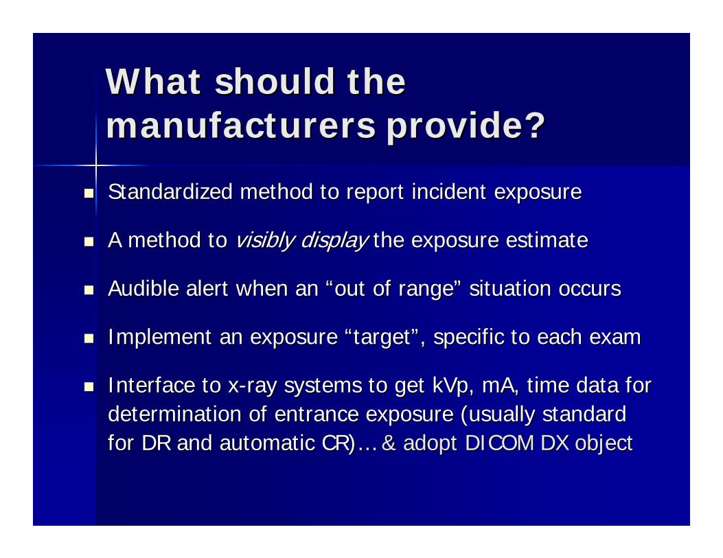
What should the What should the manufacturers provide?manufacturers provide?
Standardized method to report incident exposureStandardized method to report incident exposure
A method toA method to visibly display visibly display thethe exposure estimateexposure estimate
Audible alert when an Audible alert when an ““out of rangeout of range”” situation occurssituation occurs
Implement an exposure Implement an exposure ““targettarget””, specific to each exam, specific to each exam
Interface to xInterface to x--ray systems to get kVp, mA, time data for ray systems to get kVp, mA, time data for determination of entrance exposure (usually standard determination of entrance exposure (usually standard for DR and automatic CR)for DR and automatic CR)…… & adopt DICOM DX object& adopt DICOM DX object
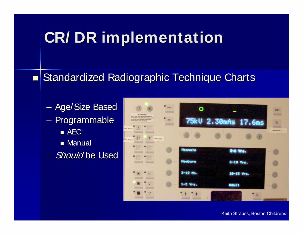
Standardized Radiographic Technique ChartsStandardized Radiographic Technique Charts
–– Age/Size BasedAge/Size Based–– Programmable Programmable
AECAECManualManual
–– Should Should be Usedbe Used
CR/DR implementationCR/DR implementation
Keith Strauss, Boston Childrens
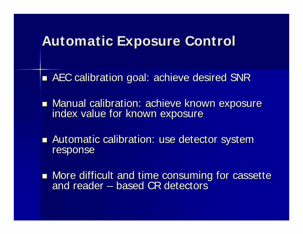
Automatic Exposure ControlAutomatic Exposure Control
AEC calibration goal: achieve desired SNRAEC calibration goal: achieve desired SNR
Manual calibration: achieve known exposure Manual calibration: achieve known exposure index value for known exposureindex value for known exposure
Automatic calibration: use detector system Automatic calibration: use detector system responseresponse
More difficult and time consuming for cassette More difficult and time consuming for cassette and reader and reader –– based CR detectorsbased CR detectors
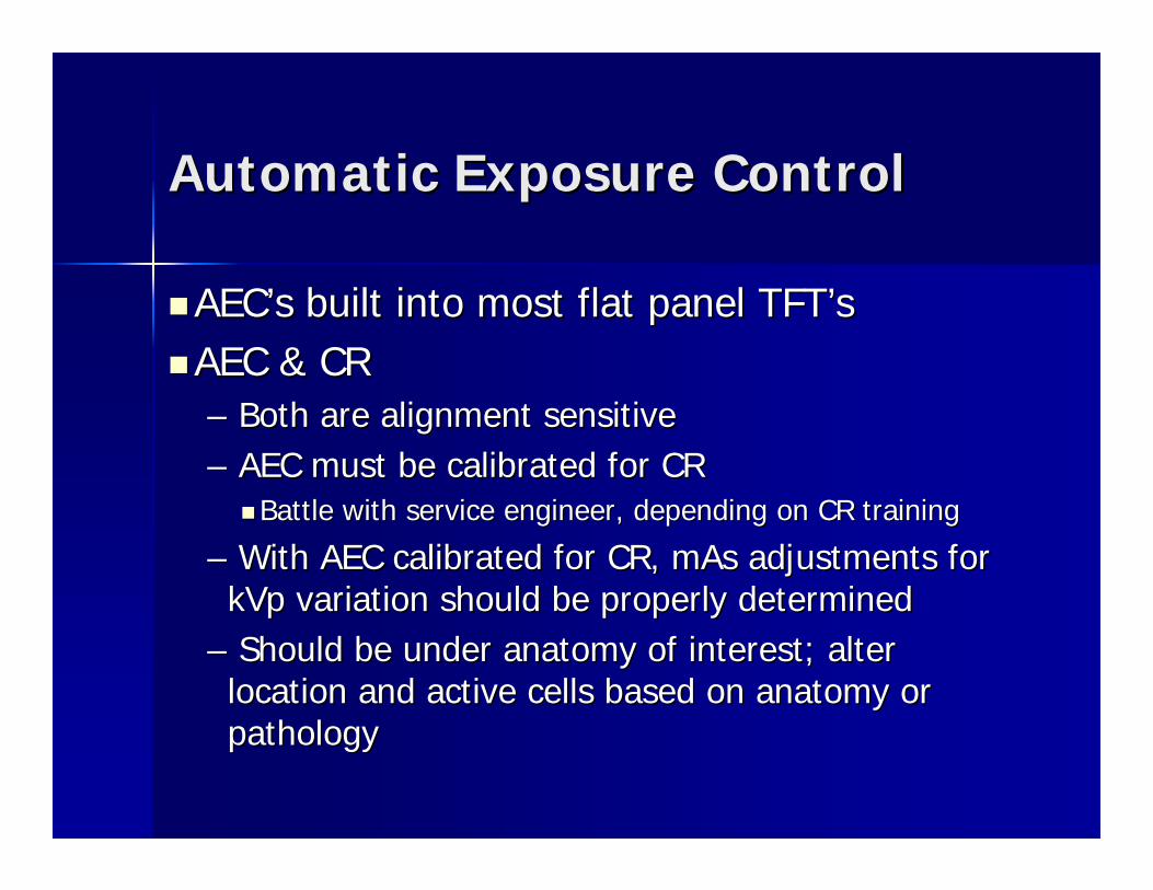
Automatic Exposure ControlAutomatic Exposure Control
AECAEC’’s built into most flat panel s built into most flat panel TFTTFT’’ssAEC & CR AEC & CR –– Both are alignment sensitiveBoth are alignment sensitive–– AEC must be calibrated for CRAEC must be calibrated for CR
Battle with service engineer, depending on CR trainingBattle with service engineer, depending on CR training
–– With AEC calibrated for CR, mAs adjustments for With AEC calibrated for CR, mAs adjustments for kVp variation should be properly determinedkVp variation should be properly determined
–– Should be under anatomy of interest; alter Should be under anatomy of interest; alter location and active cells based on anatomy or location and active cells based on anatomy or pathologypathology
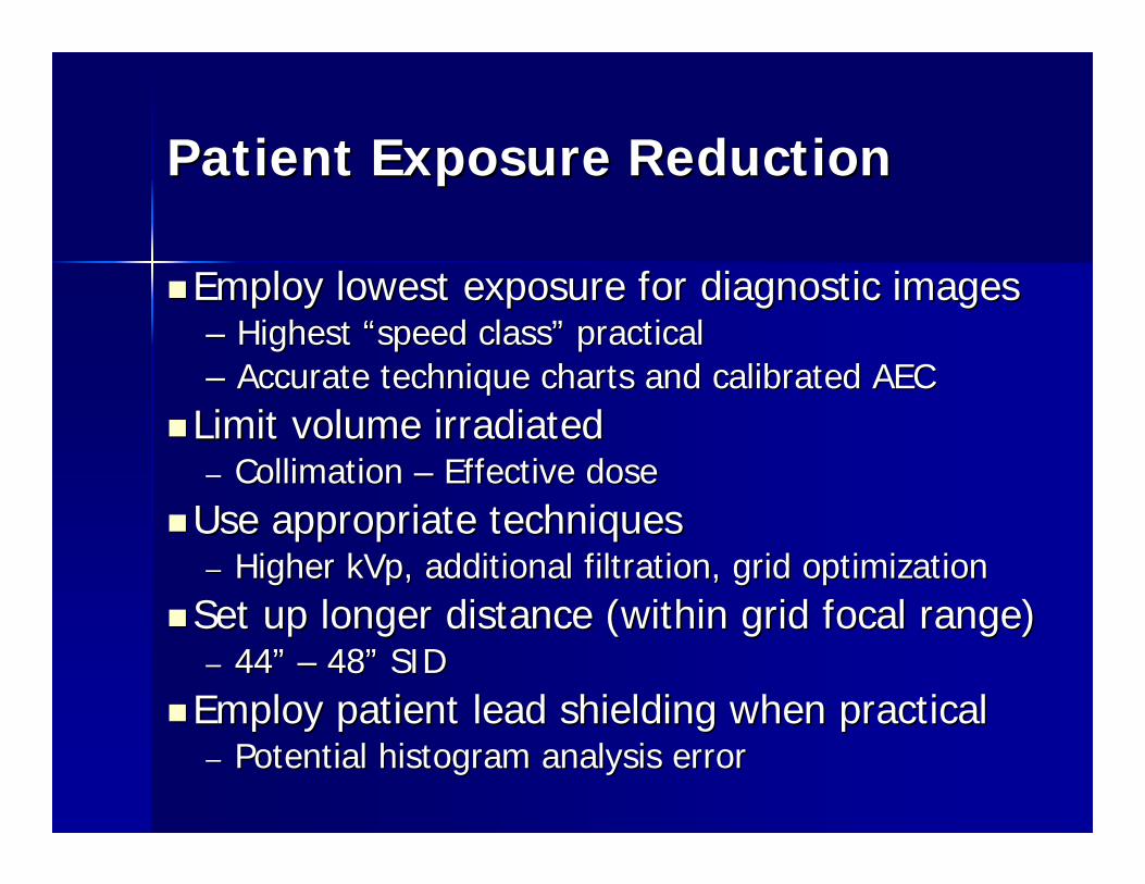
Patient Exposure ReductionPatient Exposure Reduction
Employ lowest exposure for diagnostic imagesEmploy lowest exposure for diagnostic images–– Highest Highest ““speed classspeed class”” practicalpractical–– Accurate technique charts and calibrated AECAccurate technique charts and calibrated AEC
Limit volume irradiatedLimit volume irradiated–– Collimation Collimation –– Effective doseEffective doseUse appropriate techniquesUse appropriate techniques–– Higher kVp, additional filtration, grid optimizationHigher kVp, additional filtration, grid optimizationSet up longer distance (within grid focal range)Set up longer distance (within grid focal range)–– 4444”” –– 4848”” SIDSIDEmploy patient lead shielding when practicalEmploy patient lead shielding when practical–– Potential histogram analysis errorPotential histogram analysis error
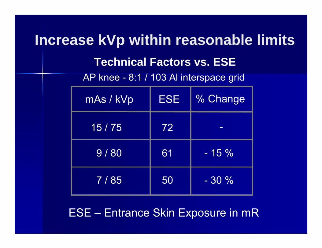
ESE – Entrance Skin Exposure in mR
Technical Factors vs. ESEAP knee - 8:1 / 103 Al interspace grid
15 / 75
9 / 80
7 / 85
72
61
50
- 15 %
- 30 %
mAs / kVp ESE % Change
-
Increase kVp within reasonable limits
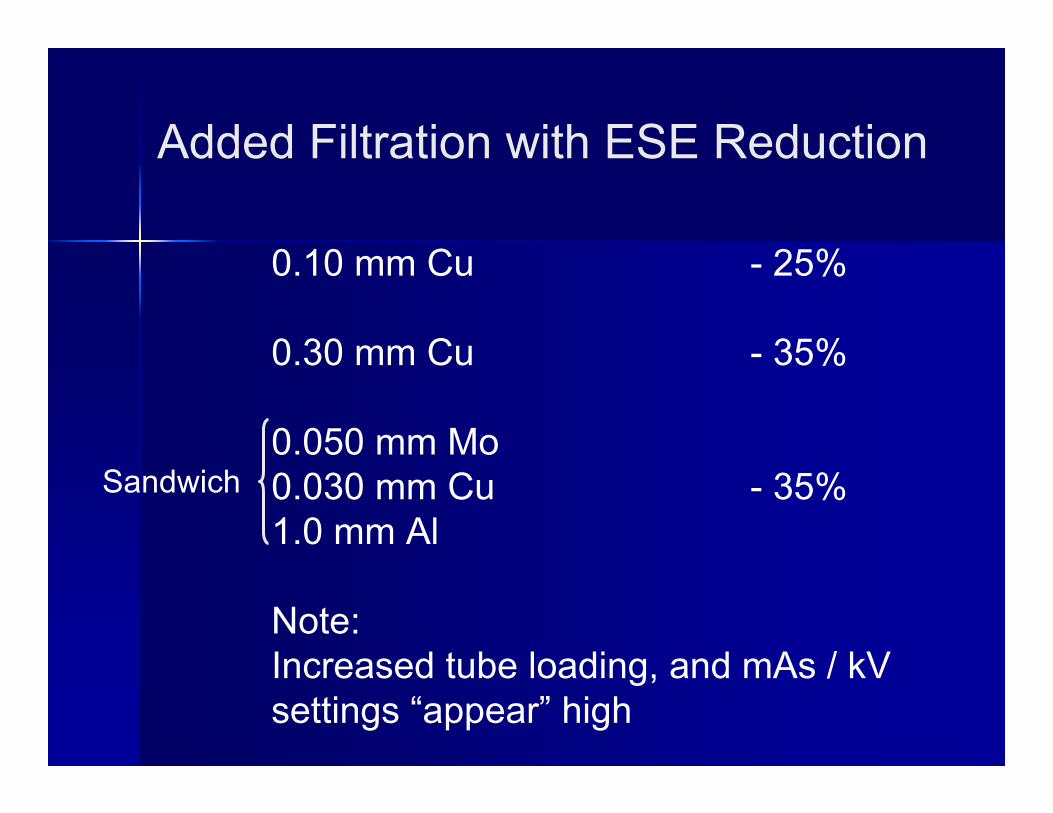
Added Filtration with ESE Reduction
0.10 mm Cu - 25%
0.30 mm Cu - 35%
0.050 mm Mo0.030 mm Cu - 35%1.0 mm Al
Note:Increased tube loading, and mAs / kV settings “appear” high
Sandwich
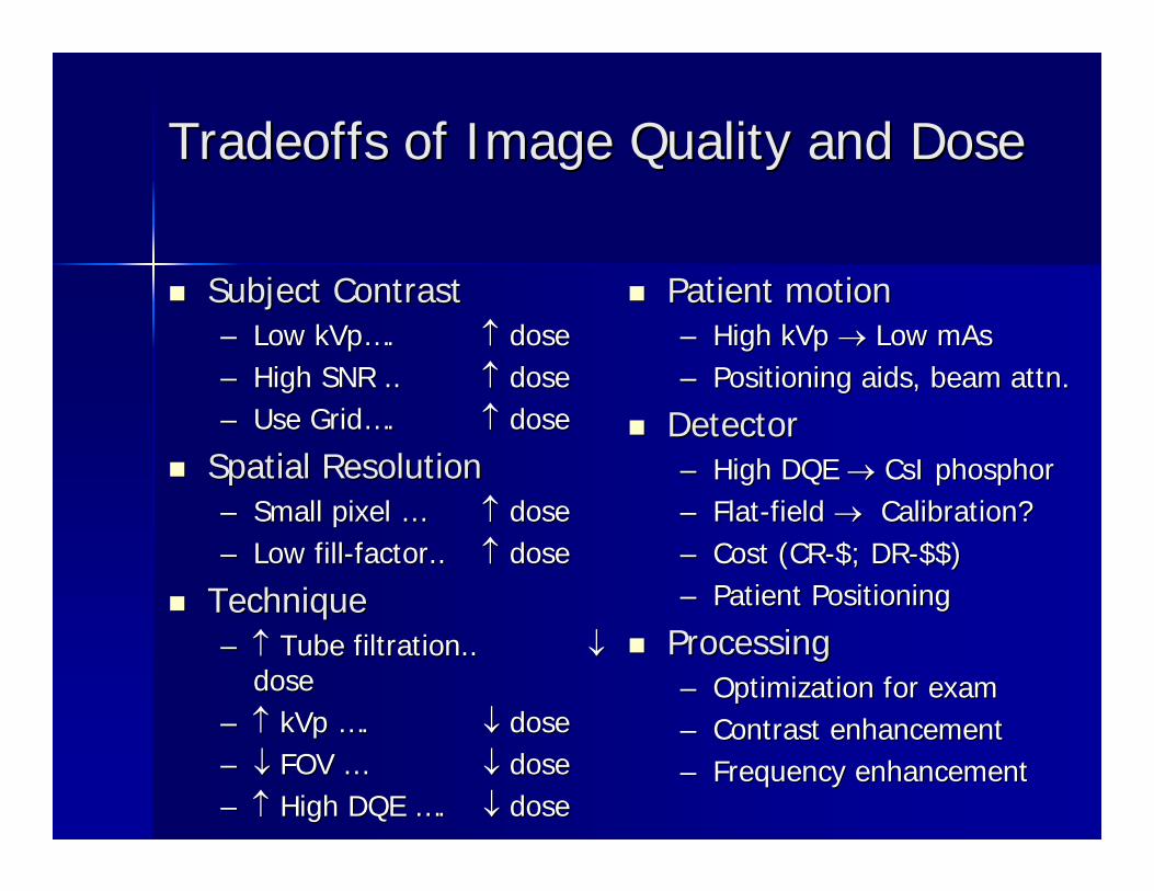
Tradeoffs of Image Quality and DoseTradeoffs of Image Quality and Dose
Subject ContrastSubject Contrast–– Low kVpLow kVp……. . ↑↑ dosedose–– High SNR .. High SNR .. ↑↑ dosedose–– Use GridUse Grid…….. ↑↑ dosedose
Spatial ResolutionSpatial Resolution–– Small pixel Small pixel …… ↑↑ dosedose–– Low fillLow fill--factor.. factor.. ↑↑ dosedose
TechniqueTechnique–– ↑↑ Tube filtration.. Tube filtration.. ↓↓
dosedose–– ↑↑ kVp kVp ……. . ↓↓ dosedose–– ↓↓ FOV FOV …… ↓↓ dosedose–– ↑↑ High DQE High DQE ……. . ↓↓ dosedose
Patient motionPatient motion–– High kVp High kVp →→ Low mAsLow mAs–– Positioning aids, beam attn.Positioning aids, beam attn.
DetectorDetector–– High DQE High DQE →→ CsI phosphorCsI phosphor–– FlatFlat--field field →→ Calibration?Calibration?–– Cost (CRCost (CR--$; DR$; DR--$$)$$)–– Patient PositioningPatient Positioning
ProcessingProcessing–– Optimization for examOptimization for exam–– Contrast enhancementContrast enhancement–– Frequency enhancementFrequency enhancement
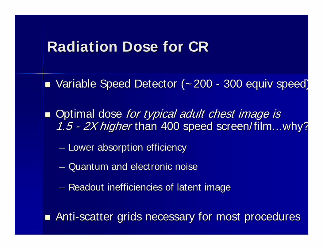
Radiation Dose for CRRadiation Dose for CR
Variable Speed Detector (~200 Variable Speed Detector (~200 -- 300 equiv speed)300 equiv speed)
Optimal doseOptimal dose for typical adult chest image is for typical adult chest image is 1.5 1.5 -- 2X higher2X higher than 400 speed screen/film...why?than 400 speed screen/film...why?
–– Lower absorption efficiencyLower absorption efficiency
–– Quantum and electronic noiseQuantum and electronic noise
–– Readout inefficiencies of latent imageReadout inefficiencies of latent image
AntiAnti--scatter grids necessary for most proceduresscatter grids necessary for most procedures
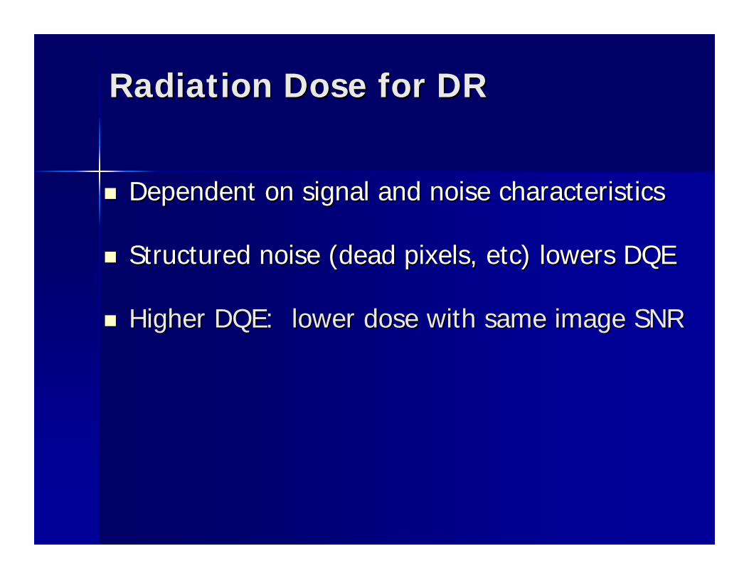
Radiation Dose for DRRadiation Dose for DR
Dependent on signal and noise characteristicsDependent on signal and noise characteristics
Structured noise (dead pixels, etc) lowers DQEStructured noise (dead pixels, etc) lowers DQE
Higher DQE: lower dose with same image SNRHigher DQE: lower dose with same image SNR
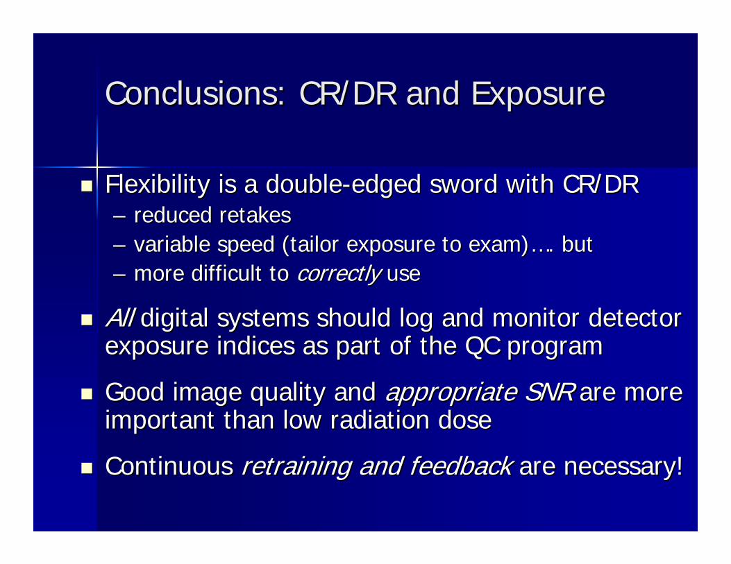
Conclusions: CR/DR and ExposureConclusions: CR/DR and Exposure
Flexibility is a doubleFlexibility is a double--edged sword with CR/DRedged sword with CR/DR–– reduced retakesreduced retakes–– variable speed (tailor exposure to exam)variable speed (tailor exposure to exam)……. but. but–– more difficult to more difficult to correctly correctly useuse
AllAll digital systems should log and monitor detector digital systems should log and monitor detector exposure indices as part of the QC programexposure indices as part of the QC program
Good image quality and Good image quality and appropriate SNRappropriate SNR are more are more important than low radiation doseimportant than low radiation dose
Continuous Continuous retrainingretraining and feedbackand feedback are necessary!are necessary!
Melissa C. Martin, M.S., FACRMelissa C. Martin, M.S., FACR
Therapy Physics Inc. Therapy Physics Inc. Gardena, CA 90248Gardena, CA 90248www.TherapyPhysics.comwww.TherapyPhysics.comee--mail: mail: [email protected]@TherapyPhysics.comOffice Phone: 310Office Phone: 310--217217--41144114