Embed Size (px)
Citation preview

RAE-Lessons by 4S7VJ 1
RADIO AMATEUR EXAM
GENERAL CLASS
By 4S7VJ
CHAPTER-7 MEASURMENTS
7.1 TEST EQUIPMENT & MEASUREMENTS
Correct operation of amateur radio equipment involves
measurements to ensure optimum performance, to comply with
the terms of the amateur transmitting licence and to avoid
interference to other users. The purpose of these
measurements is to give the operator information regarding
the conditions under which his equipment is functioning.
Basically, they are concerned with voltage, current and
frequency.

RAE-Lessons by 4S7VJ 2
Fig 7.1
7.1.1 Galvanometer
The basis of most instruments for the measurement of
voltage, current and resistance is the moving coil
galvanometer,(Fig 7.1) calibrated for microampere (A) or milli-ampere (mA) or with an arbitrary scale. If it is
calibrated for mA, it is called milliammeter. The heart of
this is a coil with very thin wire generally wound on a
rectangular former, is mounted on two pivots in the field
of a permanent magnet. The coil experiences a torque
proportional to the flow of current through it. Current is
fed to the coil through two hairsprings mounted near to
each end of the spindle. These springs also serve to return
the pointer to the zero position when the current stops.
Normally the scale is linear. This instrument can only be
used on dc, but it can be adapted to measure ac with using
a diode as a rectifier.
7.1.2 Ammeter
Milliammeters and microammeters are commonly
manufactured with basic full-scale deflection (F.S.D.) of
50A, 100A, 1mA. For higher current ratings, a shunt
resister with very low value, connected across the meter
(Fig 7.2a). There are two methods for select the correct
shunt resistor.
1. Compare with accurately calibrated ammeter and adjust the resistance of the shunt.(Fig 7.2b)
2. Calculate the resistance of the shunt with using Ohm‟s law. The following formula is derived with
using this method. (Fig 7.2c)
Fig 7.2

RAE-Lessons by 4S7VJ 3
Rs = Rm/(n-1)
Wherer, Rs is the resistance of the shunt. Rm is the
internal resistance of the milliammeter. n is the scale
multiplying factor.
n = FSD of the ammeter/ FSD of the milliammeter
Example:-
Internal resistance of a milliammeter is 10 and FSD is
1mA. What is the shunt resistor for converting it to an
ammeter with 1A of FSD?
1st Method:(with using the above formula)
Rm = 10 , n = 1A/1mA = 1000mA/1mA = 1000
Rs = Rm/(n-1) = 10/(1000-1) = 10/999 = 0.01001 or
10.01m (approximately 10m)
2nd Method: (with using Ohm’s law)
We can solve this problem without use any formula other
than Ohm‟s law.
As shown fig 7.2(c) when it is 1A FSD, the input current to
the system is 1A and it is divided into two portions; 1mA
flown through the milliammeter and the balance 999mA is
passing through the shunt resistor „Rs‟. Now apply Ohm‟s
law (V = I R) to the milliammeter
V = 0.001x10 because I = 1mA = 0.001A, R = 10
= 0.01 volt
Now apply Ohm‟s law for the shunt resistor, Rs
0.01 = 0.999xRs Because V=0.01 (voltage across the milliammter
and shunt resistor are same), I = 0.999A
Therefore Rs = 0.01/0.999
= 0.01001 (10.01m)
= 10m (Approximately)
For this shunt resistor you can use a piece of copper wire.
If you use 20swg copper wire, about 30cm is suitable.

RAE-Lessons by 4S7VJ 4
7.1.3 Volt meter
Fig 7.3
A milliammeter may be used to read small dc voltages;
few milli volts. For example, if the FSD 0.5mA and the
internal resistance 100, by using Ohm‟s law, the voltage between the terminals of the meter is 0.5x100 or 50mV. That
means it can be used as a mV meter with 50mV FSD. We can
calibrate the scale accordingly.
It is possible to extend the scale or use to read
higher voltages by connecting a large resistor (multiplier)
in series with it (Fig 7.3a). The value of this resistor
depends on the FSD of the meter (original FSD and extended
FSD) and may be calculated from Ohm‟s law. The following
formula can be used for the calculation:
Rs = Rm x( n-1)
Where n = FSD of voltmeter/FSD of mV-meter
If n is a large value (100 or more), n and n-1 approximatly
equal, then
Rs = Rm x n
Where Rs is the value of the series resistor and Rm is
the internal resistance of the meter and n is the scale
multiplying factor;

RAE-Lessons by 4S7VJ 5
Example:-
Internal resistance of a milliammeter is 10 and FSD is
10mA. What is the series resistor for converts it into a
voltmeter with 10V of FSD?
1st methode:- (using the formula)
Apply Ohm‟s low for the milliammeter, then
FSD voltage = 10mA x 10
= 0.01A x 10 = 0.1V
n = 10V/0.1V
= 100
Rm = 10
Rs = Rm x(n-1)
= 10 x (100-1)
= 990 (approximately 1k )
2nd Methode:- With using Ohm‟s law (without formula)
Apply Ohm‟s law for the milliammeter
V = IR
I = 10mA = 0.01A, R = Rm = 10
Therefore V = 0.01 x 10
= 0.1 volt
Now apply the Ohm‟s law for the series resistor-Rs
V = 10-0.1 = 9.9 volt, I = 10mA =0.01A
V = IR
Therfore 9.9 = 0.01 x Rs
Rs = 9.9/0.01
= 990 (approximatly 1k)
7.1.4 Ohm meter
Fig 7.4
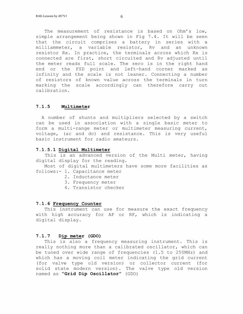
RAE-Lessons by 4S7VJ 6
The measurement of resistance is based on Ohm‟s low,
simple arrangement being shown in Fig 7.4. It will be seen
that the circuit comprises a battery in series with a
milliammeter, a variable resistor, Rv and an unknown
resistor Rx. In practice, the terminals across which Rx is
connected are first, short circuited and Rv adjusted until
the meter reads full scale. The zero is in the right hand
end or the FSD point and left-hand corner marked as
infinity and the scale is not leaner. Connecting a number
of resistors of known value across the terminals in turn
marking the scale accordingly can therefore carry out
calibration.
7.1.5 Multimeter
A number of shunts and multipliers selected by a switch
can be used in association with a single basic meter to
form a multi-range meter or multimeter measuring current,
voltage, (ac and dc) and resistance. This is very useful
basic instrument for radio amateurs.
7.1.5.1 Digital Multimeter
This is an advanced version of the Multi meter, having
digital display for the reading.
Most of digital multimeters have some more facilities as
follows:- 1. Capacitance meter
2. Inductance meter
3. Frequency meter
4. Transistor checker
7.1.6 Frequency Counter
This instrument can use for measure the exact frequency
with high accuracy for AF or RF, which is indicating a
digital display.
7.1.7 Dip meter (GDO)
This is also a frequency measuring instrument. This is
really nothing more than a calibrated oscillator, which can
be tuned over wide range of frequencies (1.5 to 250MHz) and
which has a moving coil meter indicating the grid current
(for valve type old version) or collector current (for
solid state modern version). The valve type old version
named as “Grid Dip Oscillator” (GDO)

RAE-Lessons by 4S7VJ 7
Since the Dip Meter provides it‟s own RF energy it does
not require the circuit being checked to be energized. It
is therefore useful for checking the resonant frequency of
tuned circuits or antenna systems.
The Dip Meter is also useful as an absorption wavemeter
or simple signal generator.
Fig 7.5 (Dip meter)

RAE-Lessons by 4S7VJ 8
7.1.8 Osciloscope
The oscilloscope is one of the most versatile
instruments an amateur can possess and permits the visual
display of AF and RF signals. It is particularly useful for
monitoring the wave-form, measure the frequency and
voltage.
Fig 7.6 shows an Oscilloscope with the wave-form of a
sin-wave signal. If two sin-wave signals input as the
horizontal and vertical deflections, the result will be
special kind of a curve called as “Lissajous” curve. The
shape of this curve depends on the ratio of two frequencies
and the phase difference.
Fig 7.6 (Oscilloscope)

RAE-Lessons by 4S7VJ 9
7.1.9 RF milliammeter
Measuring RF current and voltages, there is a special
type of a milliammeter, using with a thermocouple. The
measuring current is passing through a resistance wire,
therefore it is getting heated. Junction of a thermocouple
is connected to the middle portion of this wire and two
terminals of the thermocouple are connected to an ordinary
galvanometer. While heating the junction of the
thermocouple junction small dc voltage is generating and it
is measured by the galvanometer. The meter should be
calibrated for RF voltage or current accordingly.
Fig 7.7
7.2 POWER MEASURMENTS
Power in dc circuit is determined by measuring the
current and voltage. When these are known, the power is
equal to the voltage multiply by the current. If the
voltage in Volts and current in Amperes, then the power
will be in Watts.( W = VI )
Multiplication of the RF current and the voltage of a
TX is the RF power output. If it is properly matched to the
transmission line, it can be calculate with using the RF
current and the characteristic impedance of the
transmission line. (W = I²Z, W = V² / Z ) More convenient way is to measure the dc input
power of the RF amplifier. For valve amplifiers this power
is proportional to the anode current or cathode current of
the final valve because the anode voltage is a constant,
known value.
For solid state amplifiers it is proportional to the
collector current of the final power transistors.
RAE-Lessons by 4S7VJ 10
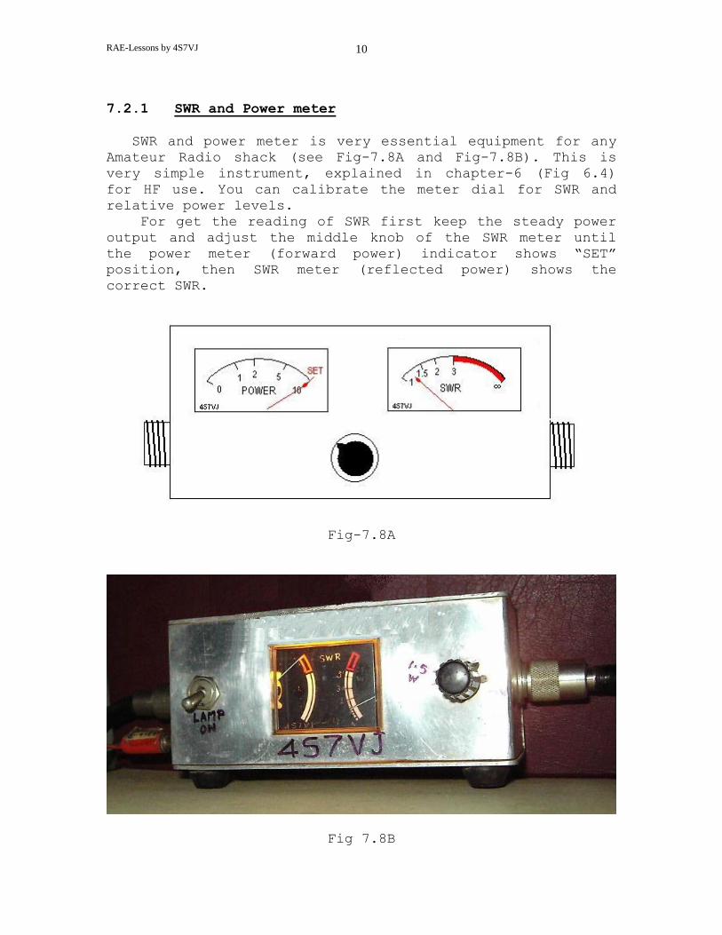
7.2.1 SWR and Power meter
SWR and power meter is very essential equipment for any
Amateur Radio shack (see Fig-7.8A and Fig-7.8B). This is
very simple instrument, explained in chapter-6 (Fig 6.4)
for HF use. You can calibrate the meter dial for SWR and
relative power levels.
For get the reading of SWR first keep the steady power
output and adjust the middle knob of the SWR meter until
the power meter (forward power) indicator shows “SET”
position, then SWR meter (reflected power) shows the
correct SWR.
Fig-7.8A
Fig 7.8B
RAE-Lessons by 4S7VJ 11
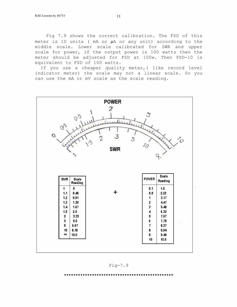
Fig 7.9 shows the correct calibration. The FSD of this
meter is 10 units ( mA or μA or any unit) according to the middle scale. Lower scale calibrated for SWR and upper
scale for power, if the output power is 100 watts then the
meter should be adjusted for FSD at 100w. Then FSD-10 is
equivalent to FSD of 100 watts.
If you use a cheaper quality meter,( like record level
indicator meter) the scale may not a linear scale. So you
can use the mA or mV scale as the scale reading.
Fig-7.9
***********************************************

RAE-Lessons by 4S7VJ 12
EXERCISES
7.1 FSD of a moving coil meter is 500 μA and the internal
resistance is 200Ω. If it is converts to an Ammeter
with 10A of FSD what is the value of shunt resister?
(Ans:- 10 m Ω) 7.2 FSD for voltage and current of a moving coil instrument
are 10mV and 0.2mA If it is converts to:
(a) Ammeter having 10A, FSD
(b) DC Voltmeter having FSD of 150V
(c) AC Voltmeter having FSD of 300V
How do you connect a shunt or series resistor and draw
a circuit diagram.
Ans:- (a) 1m Ω parallel with meter
(b) 749950 Ω or approximately 750kΩ
resistor with series
(c) 750kΩ resistor and diode in series