Embed Size (px)
Citation preview

Installation and operating instructions
Radio Frequency Twin Channel Programmable Room Thermostat and Receiver
Greenstar Comfort II RF
UK/IE
select
advance
menu
6720810965-00.1Wo
select
advance
For EMS compatible Worcester Greenstar condensing boilers
6720
8109
65 (2
014/
07)
Contents
Contents
1 Key to symbols and safety instructions . . . . . . . . . . . 31.1 Key to symbols . . . . . . . . . . . . . . . . . . . . . . . . . . . . 31.2 General safety instructions . . . . . . . . . . . . . . . . . . 3
2 Comfort II RF . . . . . . . . . . . . . . . . . . . . . . . . . . . . . . . . . 42.1 Programmable room thermostat . . . . . . . . . . . . . 42.2 Receiver . . . . . . . . . . . . . . . . . . . . . . . . . . . . . . . . . 5
3 Comfort II RF installation . . . . . . . . . . . . . . . . . . . . . . . 53.1 Receiver mounting . . . . . . . . . . . . . . . . . . . . . . . . . 53.2 Programmable room thermostat mounting . . . . . 63.3 Date and time set up . . . . . . . . . . . . . . . . . . . . . . . 73.4 Pairing/Unpairing the units . . . . . . . . . . . . . . . . . . 83.4.1Programmable room thermostat - Installer menu -
Radio settings - Pairing/Unpairing mode . . . . . .83.4.2Receiver - Pair/Unpair . . . . . . . . . . . . . . . . . . . . . . 8
4 Operation . . . . . . . . . . . . . . . . . . . . . . . . . . . . . . . . . . . . 84.1 Normal operation . . . . . . . . . . . . . . . . . . . . . . . . . . 84.2 Programmable room thermostat . . . . . . . . . . . . . 94.2.1Room temperature indication in Auto mode . . . . 94.2.2Room temperature indication in the On mode . . . 94.2.3Room temperature indication in the Off mode . . 94.2.4Setting a new room temperature . . . . . . . . . . . . 10
5 Programmable room thermostat settings . . . . . . . . 105.1 User . . . . . . . . . . . . . . . . . . . . . . . . . . . . . . . . . . . 105.1.1Heating . . . . . . . . . . . . . . . . . . . . . . . . . . . . . . . . 105.1.2HW (Hot water) . . . . . . . . . . . . . . . . . . . . . . . . . . 115.1.3Holiday function . . . . . . . . . . . . . . . . . . . . . . . . . 125.1.4Info . . . . . . . . . . . . . . . . . . . . . . . . . . . . . . . . . . . . 125.1.5Setting . . . . . . . . . . . . . . . . . . . . . . . . . . . . . . . . . 125.2 Installer . . . . . . . . . . . . . . . . . . . . . . . . . . . . . . . . 145.3 Key lock . . . . . . . . . . . . . . . . . . . . . . . . . . . . . . . . 15
6 Receiver . . . . . . . . . . . . . . . . . . . . . . . . . . . . . . . . . . . . 166.1 Override push button . . . . . . . . . . . . . . . . . . . . . 166.2 Pairing/Unpairing . . . . . . . . . . . . . . . . . . . . . . . . 16
7 Troubleshooting . . . . . . . . . . . . . . . . . . . . . . . . . . . . . 177.1 Temperature related faults . . . . . . . . . . . . . . . . . 177.2 Programmable Room thermostat and Receiver
related faults . . . . . . . . . . . . . . . . . . . . . . . . . . .177.2.1Programmable Room thermostat . . . . . . . . . . . . 177.2.2Receiver . . . . . . . . . . . . . . . . . . . . . . . . . . . . . . . . 17
8 Servicing . . . . . . . . . . . . . . . . . . . . . . . . . . . . . . . . . . . . 18
9 Maintenance . . . . . . . . . . . . . . . . . . . . . . . . . . . . . . . . 189.1 Programmable room thermostat battery
replacement . . . . . . . . . . . . . . . . . . . . . . . . . . .18
10 ErP Class . . . . . . . . . . . . . . . . . . . . . . . . . . . . . . . . . . . . 19
11 Environment / disposal . . . . . . . . . . . . . . . . . . . . . . . 19
2 Comfort II– 6720810965 (2014/07)
Key to symbols and safety instructions
1 Key to symbols and safety instructions
1.1 Key to symbols
Warnings
The following keywords are defined and can be used in this document:• NOTICE indicates a situation that could result in damage to
property or equipment.• CAUTION indicates a situation that could result in minor to
medium injury.• WARNING indicates a situation that could result in severe
injury or death.• DANGER indicates a situation that will result in severe
injury or death.
Important information
Additional symbols
Abbreviations
Definitions (DST/BST)Daylight Saving Time (DST) and British Summer Time (BST) begins on the last Sunday in March at 1:00am GMT and clocks are put forward by one hour.British Summer Time (BST) ends on the last Sunday in October at 2:00am BST and the clocks are put back by one hour.
1.2 General safety instructionsThese installation instructions are intended for heating engineers, and electricians.▶ Read any installation instructions (boiler, heating controls,
etc.) carefully before starting the installation.▶ Observe the safety instructions and warnings.▶ Observe national and regional regulations, technical rules
and guidelines.▶ Record all work carried out.
Appliance operationThis appliance can be used by children aged from 8 years and above and persons with reduced physical, sensory or mental capabilities or lack of experience and knowledge if they have been given supervision or instruction concerning use of the appliance in a safe way and understand the hazards involved. Children shall not play with the appliance. Cleaning and user maintenance shall not be made by children without supervision. (BS EN 60335-1 2012)
Installation, commissioning and servicingInstallation, commissioning and servicing must only be carried out by a competent engineer.▶ Only use original spares.
Electrical workElectrical work must only be carried out by a qualified electrician.▶ Before starting electrical work:
– Isolate the mains electrical supply and secure against unintentional re-connection.
– Check for zero voltage.▶ Also observe connection diagrams of other system
components.
Handover to the userWhen handing over, instruct the user how to operate the heating system and inform him about its operating conditions.▶ Explain how to operate the heating system and draw the
user's attention to any safety-relevant action.▶ Explain that modifications and repairs must only be carried
out by an authorised contractor.▶ Advise the user to have the system serviced annually by a
competent engineer.▶ Leave the this instruction manual with the user or at the
appliance.
Warnings in this document are identified by a warning triangle printed against a grey background.Keywords at the start of a warning indicate the type and seriousness of the ensuing risk if measures to prevent the risk are not taken.
This symbol indicates important information where there is no risk to people or property.
Symbol Explanation▶ Step in an action sequence Cross-reference to another part of the document• List entry– List entry (second level)
CH = Central HeatingDHW = Domestic Hot WaterRF = Radio FrequencyDST = Daylight Savings TimeBST = British Summer TimeGMT = Greenwich mean timeRPB = Rotary Push Button
3Comfort II– 6720810965 (2014/07)
Comfort II RF
2 Comfort II RFThe Comfort II RF comprises a wall mounted twin channel RF programmable room thermostat and a boiler or wall mounted RF receiver.
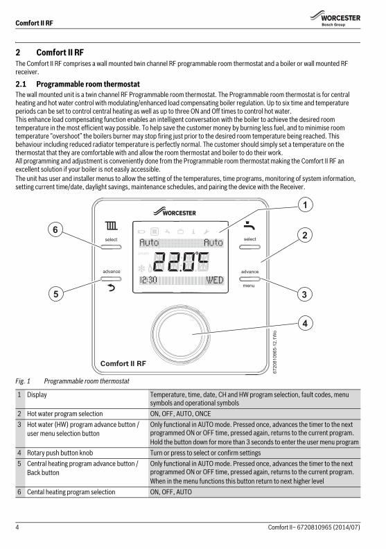
2.1 Programmable room thermostatThe wall mounted unit is a twin channel RF Programmable room thermostat. The Programmable room thermostat is for central heating and hot water control with modulating/enhanced load compensating boiler regulation. Up to six time and temperature periods can be set to control central heating as well as up to three ON and Off times to control hot water. This enhance load compensating function enables an intelligent conversation with the boiler to achieve the desired room temperature in the most efficient way possible. To help save the customer money by burning less fuel, and to minimise room temperature “overshoot” the boilers burner may stop firing just prior to the desired room temperature being reached. This behaviour including reduced radiator temperature is perfectly normal. The customer should simply set a temperature on the thermostat that they are comfortable with and allow the room thermostat and boiler to do their work.All programming and adjustment is conveniently done from the Programmable room thermostat making the Comfort II RF an excellent solution if your boiler is not easily accessible.The unit has user and installer menus to allow the setting of the temperatures, time programs, monitoring of system information, setting current time/date, daylight savings, maintenance schedules, and pairing the device with the Receiver.
Fig. 1 Programmable room thermostat
1 Display Temperature, time, date, CH and HW program selection, fault codes, menu symbols and operational symbols
2 Hot water program selection ON, OFF, AUTO, ONCE3 Hot water (HW) program advance button /
user menu selection buttonOnly functional in AUTO mode. Pressed once, advances the timer to the next programmed ON or OFF time, pressed again, returns to the current program.Hold the button down for more than 3 seconds to enter the user menu program
4 Rotary push button knob Turn or press to select or confirm settings5 Central heating program advance button /
Back buttonOnly functional in AUTO mode. Pressed once, advances the timer to the next programmed ON or OFF time, pressed again, returns to the current program.When in the menu functions this button return to next higher level
6 Cental heating program selection ON, OFF, AUTO
select
advance
select
advance
menu
Comfort II RF
pmam
6
5
1
2
3
4
6720
8109
65-1
2.1W
o
4 Comfort II– 6720810965 (2014/07)
Comfort II RF installation
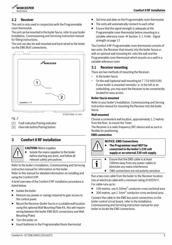
2.2 ReceiverThis unit is only used in conjunction with the Programmable room thermostat.The unit can be mounted in the boiler fascia, refer to your boiler Installation, Commissioning and Servicing instruction manual for fitting instructions.The unit can also be wall mounted and hard-wired to the boiler via the EMS BUS connections.
Fig. 2[1] Fault indicator/Pairing indicator[2] Override button/Pairing button
3 Comfort II RF installation
Refer to the boiler’s Installation, Commissioning and Servicing instruction manual for information on the boiler.Refer to this manual for detailed information on installing and using the Comfort II RF.A brief overview of the Comfort II RF installation procedure is listed below:▶ Isolate the boiler▶ Remove any panels or casings required to gain access to
the control panel▶ Mount the Receiver (boiler fascia or a suitable wall location
using the optional Wall Mounting Plate Kit, this will require wiring between the boiler EMS BUS connections and Wall Mounting Plate)
▶ Turn the boiler on▶ Insert batteries in the Programmable Room thermostat
▶ Set time and date on the Programmable room thermostat▶ The units will automatically connect to each other▶ Ensure that the signal strength is adequate at the
Programmable room thermostat before mounting in a suitable reference room Section 5.1.4 Info - Signal strength on page 12
The Comfort II RF Programmable room thermostat consists of two units: the Receiver that mounts into the boiler fascia or, with an optional wall mounting kit, onto the wall and the Programmable room thermostat which mounts on a wall in a suitable reference room
3.1 Receiver mountingThere are two methods of mounting the Receiver:• In the boiler fascia• On the wall (optional wall mounting kit 7 733 600 039)
If your boiler is mounted remotely i.e. in the loft or an outbuilding, you may want the Receiver to be conveniently located for easy access
Boiler fascia mountedRefer to your boiler’s Installation, Commissioning and Serving instruction manual for mounting the Receiver into the boiler fascia.Wall mountedChoose a convenient wall location, approximately 1.2 metres from the floor, to mount the Timer. The Receiver is a radio frequency (RF) device and as such is flexible for positioning.EMS connection
Run a two core cable from the boiler to the Receiver location.Use an electrical cable with a minimum rating of H05VV-F.For cable runs up to: ▶ 100 metres, use 0.50mm2 conductor cross sectional area▶ 300 metres, use 1.5mm2 conductor cross sectional areaConnect the cable to the EMS bus point connections on the boiler control circuit board, refer to the Installation, Commissioning and Servicing instruction manual for your boiler to locate the EMS connections.
CAUTION: Mains supplies▶ Isolate the mains supplies to the boiler
before starting any work, and follow all relevant safety precautions
6720810965-15.1Wo
1
2
NOTICE: EMS Connections▶ The Programmer must NOT be
connected to the boiler’s 230 volt supply or an external 230 volt supply.
▶ Ensure that the EMS cable is at least 100mm away from any power cables to eliminate any mains interference
▶ EMS connections are not polarity sensitive
5Comfort II– 6720810965 (2014/07)
Comfort II RF installation
Optional wall mounting kit
Using the wall plate as a template, mark the position of the mounting screws.The optional wall mounting kit contains:• 2 x countersunk screws• 2 x plastic wall plugs• Wall plate• Top retainer▶ Drill two holes to suit the size and depth of the wall plugs▶ Fit the wall plugs▶ Feed the two core cable through the back of the wall plate▶ Fit the wall plate [1], ensuring that it is level and tighten the
screws to secure▶ Connect the two core cable to the terminal block, one core
to each outer connection, ignore the middle connection
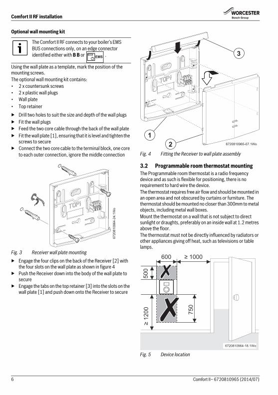
Fig. 3 Receiver wall plate mounting▶ Engage the four clips on the back of the Receiver [2] with
the four slots on the wall plate as shown in figure 4▶ Push the Receiver down into the body of the wall plate to
secure▶ Engage the tabs on the top retainer [3] into the slots on the
wall plate [1] and push down onto the Receiver to secure
Fig. 4 Fitting the Receiver to wall plate assembly
3.2 Programmable room thermostat mountingThe Programmable room thermostat is a radio frequency device and as such is flexible for positioning, there is no requirement to hard wire the device.The thermostat requires free air flow and should be mounted in an open area and not obscured by curtains or furniture. The thermostat should be mounted no closer than 300mm to metal objects, including metal wall boxes.Mount the thermostat on a wall that is not subject to direct sunlight or draughts, preferably on an inside wall at 1.2 metres above the floor.The thermostat must not be directly influenced by radiators or other appliances giving off heat, such as televisions or table lamps.
Fig. 5 Device location
The Comfort II RF connects to your boiler’s EMS BUS connections only, on an edge connector identified either with B B or .
6720
8109
64-2
4.1W
o
6720810965-07.1Wo
12
3
≥ 1000
≥ 12
00 750
600
°C°F
6720810964-18.1Wo
500
6 Comfort II– 6720810965 (2014/07)
Comfort II RF installation
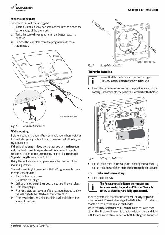
Wall mounting plateTo remove the wall mounting plate:1. Insert a suitable flat bladed screwdriver into the slot on the
bottom edge of the thermostat2. Twist the screwdriver gently until the bottom catch is
released.3. Remove the wall plate from the programmable room
thermostat.
Fig. 6 Remove back plate
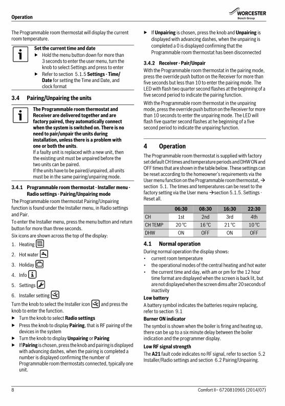
Wall mountingBefore mounting the room Programmable room thermostat on the wall, it is good practice to find a position that affords good signal strength.If the signal strength is low, try another position in that room until the best possible signal strength is obtained, refer to section 5.1 to enter the User menu and then the paragraph Signal strength in section 5.1.4.Using the wall plate as a template, mark the position of the mounting screws.The wall mounting kit provided with the Programmable room thermostat contains:• 2 x countersunk screws• 2 x plastic wall plugs▶ Drill two holes to suit the size and depth of the wall plugs▶ Fit the wall plugs▶ Fit the screws, but leave a sufficient amount proud to allow
the wall plate to be fitted over the screw heads▶ Fit the wall plate, ensuring that it is level and tighten the
screws to secure
Fig. 7 Wall plate mounting
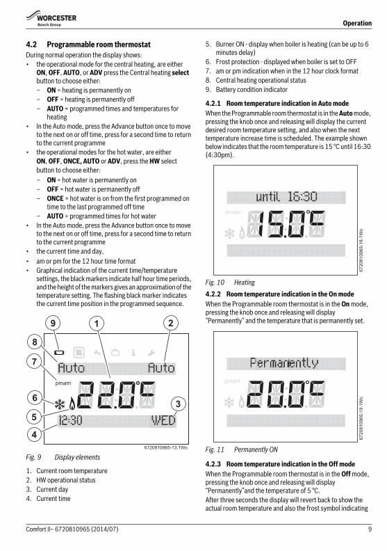
Fitting the batteries
▶ Insert the batteries ensuring that the positive + end of the battery is inserted into the positive + terminal of the holder.
Fig. 8 Fitting the batteries
▶ Fit the thermostat to the wall plate, locating the catches [1] on the top edge and then snap the bottom edge into place
3.3 Date and time set up▶ Turn the boiler ON
The Programmable room thermostat will initially display an error code A21 “No wireless signal to EMS interface”, refer to chapter 7 for information on fault codes.When they have established RF communications with each other, the display will revert to a factory default time and date with the control in “Auto” mode for both heating and hot water.
6720810965-09.1Wo
2.
1.
Ensure that the batteries are the correct type (LR6/AA) and oriented as shown in figure 8
The Programmable Room thermostat and Receiver are factory set and “Paired” to each other, so that they are fully operational.
6720810965-08.1Wo
6720
8109
65-1
0.1W
o
+
+
1
7Comfort II– 6720810965 (2014/07)
Operation
The Programmable room thermostat will display the current room temperature.
3.4 Pairing/Unpairing the units
3.4.1 Programmable room thermostat - Installer menu - Radio settings - Pairing/Unpairing mode
The Programmable room thermostat Pairing/Unpairing function is found under the Installer menu, in Radio settings and Pair.To enter the Installer menu, press the menu button and return button for more than three seconds.Six icons are shown across the top of the display:1. Heating
2. Hot water
3. Holiday
4. Info
5. Settings
6. Installer setting Turn the knob to select the Installer icon and press the knob to enter the function.▶ Turn the knob to select Radio settings▶ Press the knob to display Pairing, that is RF pairing of the
devices in the system▶ Turn the knob to display Unpairing or Pairing▶ If Pairing is chosen, press the knob and pairing is displayed
with advancing dashes, when the pairing is completed a number is displayed confirming the number of Programmable room thermostats connected, typically one unit.
▶ If Unpairing is chosen, press the knob and Unpairing is displayed with advancing dashes, when the unpairing is completed a 0 is displayed confirming that the Programmable room thermostat has been disconnected
3.4.2 Receiver - Pair/UnpairWith the Programmable room thermostat in the pairing mode, press the override push button on the Receiver for more than five seconds but less than 10 to enter the pairing mode. The LED with flash two quarter second flashes at the beginning of a five second period to indicate the pairing function.With the Programmable room thermostat in the unpairing mode, press the override push button on the Receiver for more than 10 seconds to enter the unpairing mode. The LED will flash five quarter second flashes at he beginning of a five second period to indicate the unpairing function.
4 OperationThe Programmable room thermostat is supplied with factory set default CH times and temperature periods and DHW ON and OFF times that are shown in the table below. These settings can be reset according to the homeowner’s requirements via the User menu function on the Programmable room thermostat, section 5.1. The times and temperatures can be reset to the factory setting via the User menu section 5.1.5. Settings - Reset all.
4.1 Normal operationDuring normal operation the display shows:• current room temperature• the operational modes of the central heating and hot water• the current time and day, with am or pm for the 12 hour
time format are displayed when the screen is back lit, but are not displayed when the screen dims after 20 seconds of inactivity
Low batteryA battery symbol indicates the batteries require replacing, refer to section 9.1Burner ON indicatorThe symbol is shown when the boiler is firing and heating up, there can be up to a six minute delay between the boiler indication and the programmer display.Low RF signal strengthThe A21 fault code indicates no RF signal, refer to section 5.2 Installer/Radio settings and section 6.2 Pairing/Unpairing.
Set the current time and date▶ Hold the menu button down for more than
3 seconds to enter the user menu, turn the knob to select Settings and press to enter
▶ Refer to section 5.1.5 Settings - Time/Date for setting the Time and Date, and clock format
The Programmable room thermostat and Receiver are delivered together and are factory paired, they automatically connect when the system is switched on. There is no need to pair/unpair the units during installation, unless there is a problem with one or both the units.If a faulty unit is replaced with a new unit, then the existing unit must be unpaired before the two units can be paired.If the units have to be paired/unpaired, all units must be in the same pairing/unpairing mode.
06:30 08:30 16:30 22:30CH 1st 2nd 3rd 4thCH TEMP 20 °C 16 °C 21 °C 10 °CDHW ON OFF ON OFF
8 Comfort II– 6720810965 (2014/07)
Operation
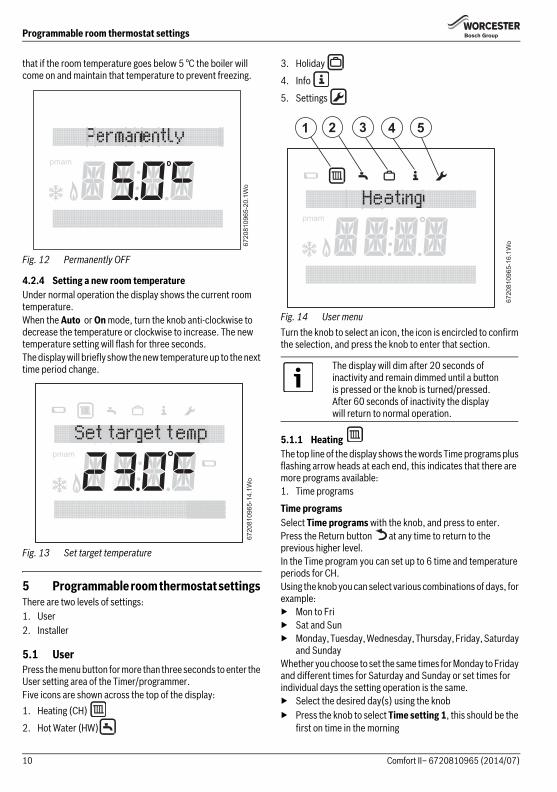
4.2 Programmable room thermostatDuring normal operation the display shows:• the operational mode for the central heating, are either
ON, OFF, AUTO, or ADV press the Central heating select button to choose either:– ON = heating is permanently on– OFF = heating is permanently off– AUTO = programmed times and temperatures for
heating• In the Auto mode, press the Advance button once to move
to the next on or off time, press for a second time to return to the current programme
• the operational modes for the hot water, are either ON, OFF, ONCE, AUTO or ADV, press the HW select button to choose either:– ON = hot water is permanently on– OFF = hot water is permanently off– ONCE = hot water is on from the first programmed on
time to the last programmed off time– AUTO = programmed times for hot water
• In the Auto mode, press the Advance button once to move to the next on or off time, press for a second time to return to the current programme
• the current time and day, • am or pm for the 12 hour time format• Graphical indication of the current time/temperature
settings, the black markers indicate half hour time periods, and the height of the markers gives an approximation of the temperature setting. The flashing black marker indicates the current time position in the programmed sequence.
Fig. 9 Display elements
1. Current room temperature2. HW operational status3. Current day4. Current time
5. Burner ON - display when boiler is heating (can be up to 6 minutes delay)
6. Frost protection - displayed when boiler is set to OFF7. am or pm indication when in the 12 hour clock format8. Central heating operational status9. Battery condition indicator
4.2.1 Room temperature indication in Auto modeWhen the Programmable room thermostat is in the Auto mode, pressing the knob once and releasing will display the current desired room temperature setting, and also when the next temperature increase time is scheduled. The example shown below indicates that the room temperature is 15 °C until 16:30 (4:30pm).
Fig. 10 Heating4.2.2 Room temperature indication in the On modeWhen the Programmable room thermostat is in the On mode, pressing the knob once and releasing will display “Permanently” and the temperature that is permanently set.
Fig. 11 Permanently ON
4.2.3 Room temperature indication in the Off modeWhen the Programmable room thermostat is in the Off mode, pressing the knob once and releasing will display “Permanently”and the temperature of 5 °C.After three seconds the display will revert back to show the actual room temperature and also the frost symbol indicating
6720810965-13.1Wo
1 2
3
4
8
7
6
5
9
pmam
6720
8109
65-1
8.1W
o
pmam
6720
8109
65-1
9.1W
o
pmam
9Comfort II– 6720810965 (2014/07)
Programmable room thermostat settings
that if the room temperature goes below 5 °C the boiler will come on and maintain that temperature to prevent freezing.
Fig. 12 Permanently OFF
4.2.4 Setting a new room temperatureUnder normal operation the display shows the current room temperature.When the Auto or On mode, turn the knob anti-clockwise to decrease the temperature or clockwise to increase. The new temperature setting will flash for three seconds.The display will briefly show the new temperature up to the next time period change.
Fig. 13 Set target temperature
5 Programmable room thermostat settings There are two levels of settings:1. User2. Installer
5.1 UserPress the menu button for more than three seconds to enter the User setting area of the Timer/programmer.Five icons are shown across the top of the display:1. Heating (CH)
2. Hot Water (HW)
3. Holiday
4. Info
5. Settings
Fig. 14 User menuTurn the knob to select an icon, the icon is encircled to confirm the selection, and press the knob to enter that section.
5.1.1 Heating The top line of the display shows the words Time programs plus flashing arrow heads at each end, this indicates that there are more programs available:1. Time programs
Time programsSelect Time programs with the knob, and press to enter.Press the Return button at any time to return to the previous higher level.In the Time program you can set up to 6 time and temperature periods for CH.Using the knob you can select various combinations of days, for example:▶ Mon to Fri▶ Sat and Sun▶ Monday, Tuesday, Wednesday, Thursday, Friday, Saturday
and SundayWhether you choose to set the same times for Monday to Friday and different times for Saturday and Sunday or set times for individual days the setting operation is the same.▶ Select the desired day(s) using the knob▶ Press the knob to select Time setting 1, this should be the
first on time in the morning
6720
8109
65-2
0.1W
o
pmam
6720
8109
65-1
4.1W
o
pmam
The display will dim after 20 seconds of inactivity and remain dimmed until a button is pressed or the knob is turned/pressed.After 60 seconds of inactivity the display will return to normal operation.
6720
8109
65-1
6.1W
o
2 3 4 51
pmam
10 Comfort II– 6720810965 (2014/07)
Programmable room thermostat settings
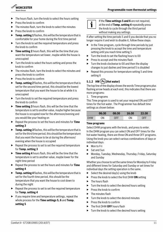
▶ The hours flash, turn the knob to select the hours setting▶ Press the knob to confirm▶ The minutes flash, turn the knob to select the minutes▶ Press the knob to confirm▶ Temp. setting 1 flashes, this will be the temperature that is
comfortable for your home during the first time period▶ Turn the knob to set the required temperature and press
the knob to confirm▶ Time setting 2 hours flash, this will be the time that you
want the temperature set lower, maybe while the house is unoccupied
▶ Turn the knob to select the hours setting and press the knob to confirm
▶ The minutes flash, turn the knob to select the minutes and press the knob to confirm
▶ Press the knob to confirm▶ Temp. setting 2 flashes, this will be the temperature that is
set for the second time period, this should be the lowest temperature that you want the house to be at while it is unoccupied
▶ Turn the knob to set the required temperature and press the knob to confirm
▶ Time setting 3 hours flash, this will be the time that the temperature is set to another value, maybe higher because the house is occupied now for the afternoon/evening and you would like your heating on
▶ Repeat the process to set the hours and minutes for Time setting 3
▶ Temp. setting 3 flashes, this will be the temperature that is set for the third time period, this should be the temperature that you want the house to be at during the afternoon/evening when the house is occupied
▶ Repeat the process to set to set the required temperature for Temp. setting 3
▶ Time setting 4 hours flash, this will be the time that the temperature is set to another value, maybe lower for the night time period
▶ Repeat the process to set the hours and minutes for Time setting 4
▶ Temp. setting 4 flashes, this will be the temperature that is set for the fourth time period, this should be the temperature that you want the house to cool down to during the night
▶ Repeat the process to set to set the required temperature for Temp. setting 4
▶ If you require time and temperature settings, repeat the whole process for the Time settings 5, 6 and Temp. setting 5
If after setting the time periods 5 and 6 you decide that you no longer require it and wish to disable it, follow these steps:▶ In the Time program, cycle through time periods by just
pressing the knob to accept the time and temperature setting until you reach time setting 5
▶ Turn the knob to set the flashing hours to 00▶ Press to accept and the minutes flash▶ Turn the knob clockwise to 00 and then the display
changes to just dashes and time period 5 is disabled▶ Repeat this process for temperature setting 5 and time
setting 6
5.1.2 HW (Hot water)The top line of the display shows the words Time programs plus flashing arrow heads at each end, this indicates that there are more programs:1. Time programsThis Time program is used to set your required ON and OFF times for the hot water. The Programmer has default time settings as shown below:
Time programsSelect DHW programs with the knob, and press to enter.In the DHW program you can select ON and OFF times for the hot water heating, there are three ON and three OFF programs.Using the knob you can select various combinations of days or individual days:▶ Mon to Fri▶ Sat and Sun▶ Monday, Tuesday, Wednesday, Thursday, Friday, Saturday
and SundayWhether you choose to set the same times for Monday to Friday and different times for Saturday and Sunday or set times for individual days the setting operation is the same.▶ Select the desired day(s) using the knob▶ Press the knob to select the first DHW ON setting▶ The hours flash▶ Turn the knob to select the desired hours setting▶ Press the knob to confirm▶ The minutes flash▶ Turn the knob to select the desired minutes▶ Press the knob to confirm▶ The first DHW OFF hours flash▶ Turn the knob to select the desired hours setting
If the Time settings 5 and 6 are not required, at the end of Temp. setting 4 repeatedly press the knob to cycle through the third period without making any settings.
06:30 08:30 16:30 22:30DHW ON OFF ON OFF
11Comfort II– 6720810965 (2014/07)
Programmable room thermostat settings
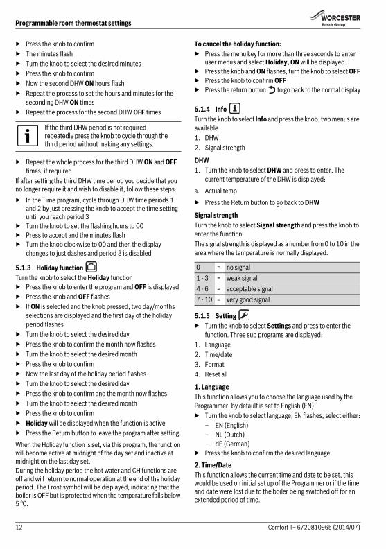
▶ Press the knob to confirm▶ The minutes flash▶ Turn the knob to select the desired minutes▶ Press the knob to confirm▶ Now the second DHW ON hours flash▶ Repeat the process to set the hours and minutes for the
seconding DHW ON times▶ Repeat the process for the second DHW OFF times
▶ Repeat the whole process for the third DHW ON and OFF times, if required
If after setting the third DHW time period you decide that you no longer require it and wish to disable it, follow these steps:▶ In the Time program, cycle through DHW time periods 1
and 2 by just pressing the knob to accept the time setting until you reach period 3
▶ Turn the knob to set the flashing hours to 00▶ Press to accept and the minutes flash▶ Turn the knob clockwise to 00 and then the display
changes to just dashes and period 3 is disabled
5.1.3 Holiday function Turn the knob to select the Holiday function▶ Press the knob to enter the program and OFF is displayed▶ Press the knob and OFF flashes▶ If ON is selected and the knob pressed, two day/months
selections are displayed and the first day of the holiday period flashes
▶ Turn the knob to select the desired day▶ Press the knob to confirm the month now flashes▶ Turn the knob to select the desired month▶ Press the knob to confirm▶ Now the last day of the holiday period flashes▶ Turn the knob to select the desired day▶ Press the knob to confirm and the month now flashes▶ Turn the knob to select the desired month▶ Press the knob to confirm▶ Holiday will be displayed when the function is active▶ Press the Return button to leave the program after setting.When the Holiday function is set, via this program, the function will become active at midnight of the day set and inactive at midnight on the last day set.During the holiday period the hot water and CH functions are off and will return to normal operation at the end of the holiday period. The Frost symbol will be displayed, indicating that the boiler is OFF but is protected when the temperature falls below 5 °C.
To cancel the holiday function:▶ Press the menu key for more than three seconds to enter
user menus and select Holiday, ON will be displayed.▶ Press the knob and ON flashes, turn the knob to select OFF▶ Press the knob to confirm OFF▶ Press the return button to go back to the normal display
5.1.4 Info Turn the knob to select Info and press the knob, two menus are available:1. DHW2. Signal strength
DHW1. Turn the knob to select DHW and press to enter. The
current temperature of the DHW is displayed:a. Actual temp▶ Press the Return button to go back to DHW
Signal strengthTurn the knob to select Signal strength and press the knob to enter the function.The signal strength is displayed as a number from 0 to 10 in the area where the temperature is normally displayed.
5.1.5 Setting ▶ Turn the knob to select Settings and press to enter the
function. Three sub programs are displayed:1. Language2. Time/date3. Format4. Reset all
1. LanguageThis function allows you to choose the language used by the Programmer, by default is set to English (EN).▶ Turn the knob to select language, EN flashes, select either:
– EN (English)– NL (Dutch)– dE (German)
▶ Press the knob to confirm the desired language
2. Time/DateThis function allows the current time and date to be set, this would be used on initial set up of the Programmer or if the time and date were lost due to the boiler being switched off for an extended period of time.
If the third DHW period is not required repeatedly press the knob to cycle through the third period without making any settings.
0 = no signal 1 - 3 = weak signal4 - 6 = acceptable signal7 - 10 = very good signal
12 Comfort II– 6720810965 (2014/07)
Programmable room thermostat settings
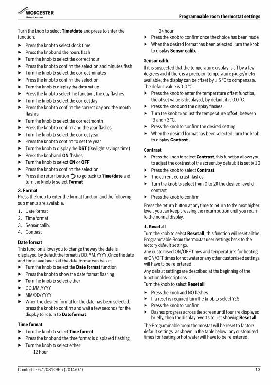
Turn the knob to select Time/date and press to enter the function:▶ Press the knob to select clock time▶ Press the knob and the hours flash▶ Turn the knob to select the correct hour▶ Press the knob to confirm the selection and minutes flash▶ Turn the knob to select the correct minutes▶ Press the knob to confirm the selection▶ Turn the knob to display the date set up▶ Press the knob to select the function, the day flashes▶ Turn the knob to select the correct day▶ Press the knob to confirm the correct day and the month
flashes▶ Turn the knob to select the correct month▶ Press the knob to confirm and the year flashes▶ Turn the knob to select the correct year▶ Press the knob to confirm to set the year▶ Turn the knob to display the DST (Daylight savings time)▶ Press the knob and ON flashes▶ Turn the knob to select ON or OFF▶ Press the knob to confirm the selection▶ Press the return button to go back to Time/date and
turn the knob to select Format3. FormatPress the knob to enter the format function and the following sub menus are available:1. Date format2. Time format3. Sensor calib.4. Contrast
Date formatThis function allows you to change the way the date is displayed, by default the format is DD.MM.YYYY. Once the date and time have been set the date format can be set:▶ Turn the knob to select the Date format function▶ Press the knob to show the date format flashing▶ Turn the knob to select either:▶ DD.MM.YYYY▶ MM/DD/YYYY▶ When the desired format for the date has been selected,
press the knob to confirm and wait a few seconds for the display to return to Date format
Time format▶ Turn the knob to select Time format▶ Press the knob and the time format is displayed flashing▶ Turn the knob to select either:
– 12 hour
– 24 hour▶ Press the knob to confirm once the choice has been made▶ When the desired format has been selected, turn the knob
to display Sensor calib.
Sensor calib.If it is suspected that the temperature display is off by a few degrees and if there is a precision temperature gauge/meter available, the display can be offset by ± 5 °C to compensate. The default value is 0.0 °C.▶ Press the knob to enter the temperature offset function,
the offset value is displayed, by default it is 0.0 °C.▶ Press the knob and the display flashes.▶ Turn the knob to adjust the temperature offset, between
-3 and +3 °C.▶ Press the knob to confirm the desired setting▶ When the desired format has been selected, turn the knob
to display Contrast
Contrast▶ Press the knob to select Contrast, this function allows you
to adjust the contrast of the screen, by default it is set to 10▶ Press the knob to select Contrast▶ The current contrast flashes▶ Turn the knob to select from 0 to 20 the desired level of
contrast▶ Press the knob to confirmPress the return button at any time to return to the next higher level, you can keep pressing the return button until you return to the normal display.
4. Reset allTurn the knob to select Reset all, this function will reset all the Programmable Room thermostat user settings back to the factory default settings. Any customised ON /OFF times and temperatures for heating or ON/OFF times for hot water or any other customised settings will have to be re-entered.Any default settings are described at the beginning of the functional descriptions.Turn the knob to select Reset all▶ Press the knob and NO flashes▶ If a reset is required turn the knob to select YES▶ Press the knob to confirm▶ Dashes progress across the screen until four are displayed
briefly, then the display reverts to just showing Reset allThe Programmable room thermostat will be reset to factory default settings, as shown in the table below, any customised times for heating or hot water will have to be re-entered.
13Comfort II– 6720810965 (2014/07)
Programmable room thermostat settings
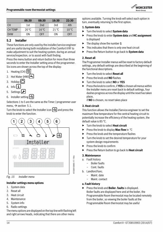
5.2 InstallerThese functions are only used by the installer/service engineer and are useful during both installation of the Comfort II RF to make adjustment to suit the heating system; during an annual service/inspection, or to assist with fault finding.Press the menu button and return button for more than three seconds to enter the Installer setting area of the programmer.Six icons are shown across the top of the display:1. Heating (CH)
2. Hot Water (HW)
3. Holiday
4. Info
5. Settings
6. Installer setting Selections 1 to 5 are the same as the Timer / programmer user menu, section 5.1.Turn the knob to select the Installer icon and press the knob to enter the function.
Fig. 15 Installer menu
Installer settings menu options1. System data2. Reset all3. Heat circuit4. Maintenance5. System info6. Radio settingsThe menu options are displayed on the top line with flashing left and right arrows heads, indicating that there are other menu
options available. Turning the knob will select each option in turn, eventually returning to the first option.
1. System data▶ Turn the knob to select System data▶ Press the knob to enter System data and HC assignment
is displayed▶ The display show the number 1▶ This indicates that there is only one heat circuit▶ Press the Return button to go back to System data
2. Reset allThe Programmer Installer menus will be reset to factory default settings, any default settings are described at the beginning of the functional descriptions.▶ Turn the knob to select Reset all▶ Press the knob and NO flashes▶ Turn the knob to select NO or YES▶ Press the knob to confirm, if YES is chosen all menus within
the Installer menu are reset back to default settings, four dashes progress across the display until the reset has taken place,if NO is chosen, no reset takes place
3. Heat circuitThis function allows the Installer/Service engineer to set the maximum flow temperature for the central heating circuit to potentially increase the efficiency of the heating system, the default value is 85 °C.▶ Turn the knob to select Heat circuit▶ Press the knob to display Max flow in °C▶ Press the knob and the temperature flashes▶ Turn the knob to set the desired temperature for your
system design requirements▶ Press the knob to confirm▶ Press the Return button to go back to Heat circuit
3. Maintenancea. Fault history
– Boiler faults– Cont. faults
b. Landlord func.– Maint. date– Maint. contact
a. Fault history▶ Press the knob and Boiler. faults is displayed.
Boiler faults are displayed here and at the boiler, the Programmable Room thermostat may be located remotely from the boiler, so viewing the boiler faults at the Programmable Room thermostat may be useful
06:30 08:30 16:30 22:30CH 1st 2nd 3rd 4thCH TEMP 20 °C 16 °C 21 °C 10 °CDHW ON OFF ON OFF
6720
8109
65-1
7.1W
o
2 3 4 5 61
pmam
14 Comfort II– 6720810965 (2014/07)
Programmable room thermostat settings
▶ Press the knob and the first of five faults is displayed with the fault code and occurrence date. The fault screens can be scrolled through using the knob. If no faults have occurred, the text No fault will be displayed
▶ Press the Return button to go back to Boiler faults▶ Turn the knob and Cont. faults is displayed▶ Press the knob and the first of five faults is displayed with
the fault code and occurrence date. The fault screens can be scrolled through using the knob. If no faults have occurred, the text No fault will be displayed.
▶ Press the Return button to go back to Cont. faults▶ Or press the Return button again to go back to Fault
History▶ Turn the knob to select Landlord func. or press the Return
button go back to Maintenanceb. Landlord func.
This function is for social housing landlords only and enables a maintenance/annual service date to be set.The maintenance reminder message “Maintenance” is displayed 30 days before the set date. Along with the Maintenance message a contact telephone number will also be displayed.The tenant should call this number to arrange a convenient date with the landlord for the service.If the maintenance reminder message is not cleared or reset to a later date, by the service engineer, then 14 days after the scheduled maintenance date the controller will limit the room temperature set point to 18°C. 4. System info1. Turn the knob to select System info2. Press the knob and Install date is displayed3. Press the knob and the install date is displayed4. Press the knob to return to Install date5. Turn the knob to select SW controller6. Press the knob to display the software controller version7. Press the knob to return to SW controller8. Press the return button to go back to System info
5. Radio settings - Pair/Unpair
When the devices are being paired, the Programmable room thermostat and Receiver must be in the same mode of pairing.Refer to section 6.2 for pairing of the Receiver.Ensure that the Programmable room thermostat is positioned as suggested in Section 3.1 and away from metal objects that might attenuate the RF signal.Before mounting the Programmable room thermostat on the wall, it is good practice to find a position that affords good signal strength.When the units have been paired, check the signal strength at the Programmable room thermostat. If the signal strength is low, try another position in that room until the best possible signal strength is obtained, refer to page 12, section 5.1.4 Info and the paragraph Signal strength for the Programmable room thermostat.▶ Turn the knob to select Radio settings▶ Press the knob to display Pairing, that is RF pairing of the
devices in the system▶ Turn the knob to display Unpairing or Pairing▶ If Pairing is chosen, press the knob and pairing is displayed
with advancing dashes, when the pairing between the devices has been made a number is displayed confirming the number of room thermostats connected
▶ If Unpairing is chosen, press the knob and Unpairing is displayed with advancing dashes, when the unpairing between the devices has been made the number 0 is displayed confirming that the room thermostat(s) have been disconnected
5.3 Key lockWhen the Key lock is active, no user interaction with the units is possible, if a button is pressed or the knob turned/pressed the word Key lock is displayed.Key lock ONTo activate the Keylock:▶ Hold down the CH Select button and the knob at the same
time for more than three seconds and the Keylock is active
Key lock OFFTo de-activate the Key lock:▶ Hold down the CH Select button and knob at the same time
for more than 3 seconds and the Key lock is de-activated
Landlords:▶ Call the Worcester Bosch technical support
team for instructions of how to set the Maintenance message or contact telephone number.
The Programmable room thermostat and Receiver are delivered together and are factory paired, they will automatically connect when the system is switched on.If the units have to be paired, all units must be in the pairing mode to be connected, refer to section 6.2 to put the Receiver into the pairing mode.
15Comfort II– 6720810965 (2014/07)
Receiver
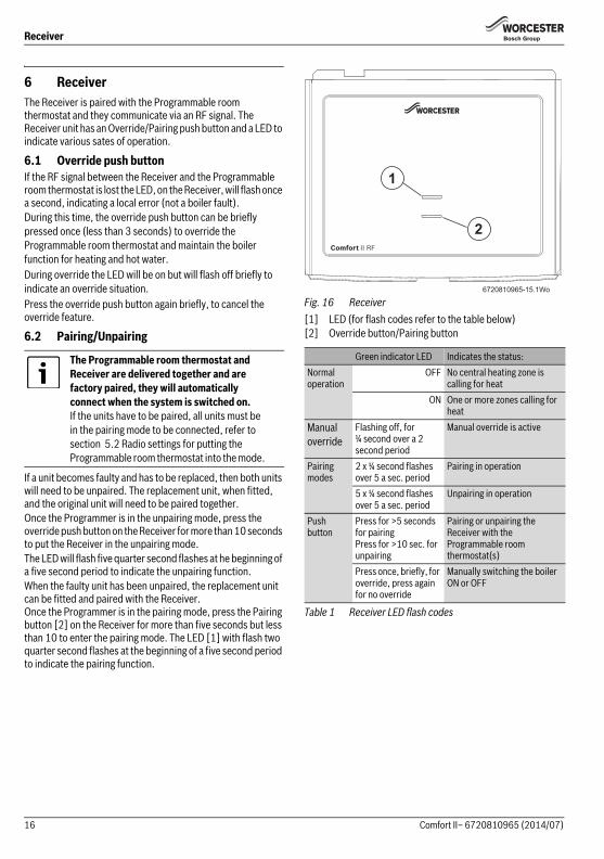
6 ReceiverThe Receiver is paired with the Programmable room thermostat and they communicate via an RF signal. The Receiver unit has an Override/Pairing push button and a LED to indicate various sates of operation.
6.1 Override push buttonIf the RF signal between the Receiver and the Programmable room thermostat is lost the LED, on the Receiver, will flash once a second, indicating a local error (not a boiler fault). During this time, the override push button can be briefly pressed once (less than 3 seconds) to override the Programmable room thermostat and maintain the boiler function for heating and hot water.During override the LED will be on but will flash off briefly to indicate an override situation.Press the override push button again briefly, to cancel the override feature.
6.2 Pairing/Unpairing
If a unit becomes faulty and has to be replaced, then both units will need to be unpaired. The replacement unit, when fitted, and the original unit will need to be paired together.Once the Programmer is in the unpairing mode, press the override push button on the Receiver for more than 10 seconds to put the Receiver in the unpairing mode. The LED will flash five quarter second flashes at he beginning of a five second period to indicate the unpairing function.When the faulty unit has been unpaired, the replacement unit can be fitted and paired with the Receiver. Once the Programmer is in the pairing mode, press the Pairing button [2] on the Receiver for more than five seconds but less than 10 to enter the pairing mode. The LED [1] with flash two quarter second flashes at the beginning of a five second period to indicate the pairing function.
Fig. 16 Receiver[1] LED (for flash codes refer to the table below)[2] Override button/Pairing button
The Programmable room thermostat and Receiver are delivered together and are factory paired, they will automatically connect when the system is switched on.If the units have to be paired, all units must be in the pairing mode to be connected, refer to section 5.2 Radio settings for putting the Programmable room thermostat into the mode.
Green indicator LED Indicates the status:Normal operation
OFF No central heating zone is calling for heat
ON One or more zones calling for heat
Manual override
Flashing off, for ¼ second over a 2 second period
Manual override is active
Pairing modes
2 x ¼ second flashes over 5 a sec. period
Pairing in operation
5 x ¼ second flashes over 5 a sec. period
Unpairing in operation
Pushbutton
Press for >5 seconds for pairingPress for >10 sec. for unpairing
Pairing or unpairing the Receiver with the Programmable room thermostat(s)
Press once, briefly, for override, press again for no override
Manually switching the boiler ON or OFF
Table 1 Receiver LED flash codes
6720810965-15.1Wo
1
2
16 Comfort II– 6720810965 (2014/07)
Troubleshooting
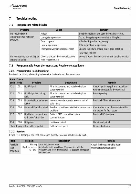
7 Troubleshooting
7.1 Temperature related faults
7.2 Programmable Room thermostat and Receiver related faults
7.2.1 Programmable Room thermostatFaults will be display alternating between the fault code and the cause code.
7.2.2 ReceiverIf the LED is flashing at one flash per second then the Receiver has detected a fault.
Problem Cause RemedyThe required room temperature has not been achieved.
Airlock Bleed the radiators and vent the heating system.Low system pressure Top up the system pressure via the filling linkTime program Is the heating on for long enoughFlow temperature Set a higher flow temperatureThermostat valve in reference room Operate the TRV to ensure that it does not stick
Fully open the TRVThe room temperature is higher that the set value
Check the Room thermostat location refer to section 3.2
Move the Room thermostat to a more suitable location
Fault code
Cause code Problem Description Remedy
A21 1001 No RF signal All units powered and not showing low battery symbol
Check signal strength and reposition Room thermostat for better signal
A22 1002 No RF signal or pairing fault
All units powered and not showing low battery symbol
Repeat pairing
A23 1003 Room stat internal sensor failure
Internal room temperature sensor out of valid range
Replace RF Room thermostat
A24 1004 Remote RF unit has a fault Another room thermostat in the system has a problem
Check other room thermostats within the system for fault codes
A27 1007 Unable to communicate with boiler’s EMS bus
Boiler is EMS compatible but no communication
Replace EMS interface
A28 1008 Not paired Unit is not paired Unpair and pair allBlank display or low battery symbol Batteries are spent Replace batteries
Fault Problem Description RemedyPossible fault condition
Flashing1 flash per second
(1 Hertz)
Local programmer error. Not a boiler fault, possibly no RF connection with the Programmable room thermostat(s), at least one connection has been lost
Check the Programmable Room thermostats for fault code.
17Comfort II– 6720810965 (2014/07)
Servicing
8 ServicingThese units can not be serviced.Should either unit fail to function correctly check that the:▶ Programmable room thermostat settings are correct▶ RF signal link between the units is set up correctly,
sections 6.2 and page 15 Radio settings▶ Programmable room thermostat batteries are the correct
type, fitted correctly and are not exhausted.If in doubt, fit new batteries section 9.1.
9 MaintenanceThese units require no maintenance apart from replacing used batteries in the programmable room thermostat.The outer casing can be wiped clean using a dry cloth, do not used polish or detergents.
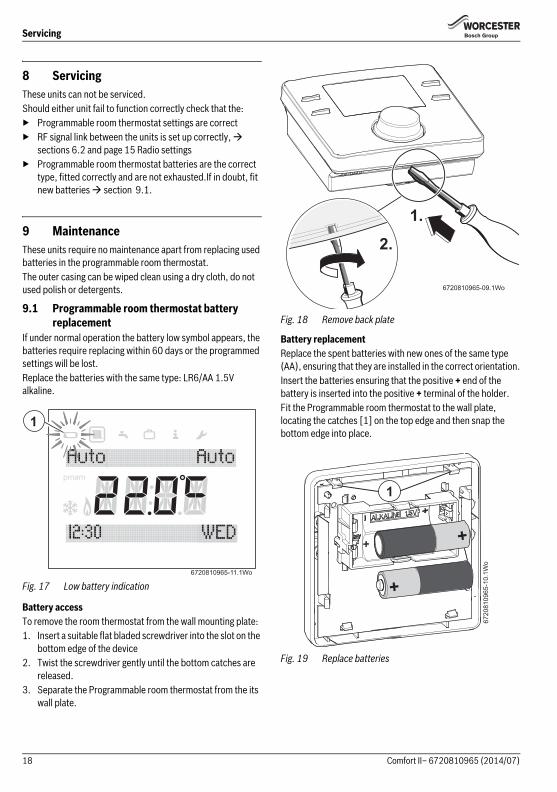
9.1 Programmable room thermostat battery replacement
If under normal operation the battery low symbol appears, the batteries require replacing within 60 days or the programmed settings will be lost.Replace the batteries with the same type: LR6/AA 1.5V alkaline.
Fig. 17 Low battery indication
Battery accessTo remove the room thermostat from the wall mounting plate:1. Insert a suitable flat bladed screwdriver into the slot on the
bottom edge of the device2. Twist the screwdriver gently until the bottom catches are
released.3. Separate the Programmable room thermostat from the its
wall plate.
Fig. 18 Remove back plate
Battery replacementReplace the spent batteries with new ones of the same type (AA), ensuring that they are installed in the correct orientation.Insert the batteries ensuring that the positive + end of the battery is inserted into the positive + terminal of the holder.Fit the Programmable room thermostat to the wall plate, locating the catches [1] on the top edge and then snap the bottom edge into place.
Fig. 19 Replace batteries
6720810965-11.1Wo
1
pmam
6720810965-09.1Wo
2.
1.
6720
8109
65-1
0.1W
o
+
+
1
18 Comfort II– 6720810965 (2014/07)
ErP Class
10 ErP ClassThe data represented in the table below is required for the completion of Energy Related Product (ErP) Directive System Package fiche and, subsequently, the ErP system data label. ERP Labelling obligation applicable from 26th September 2015.
11 Environment / disposalEnvironmental protection is a fundamental corporate strategyof the Bosch Group.The quality of our products, their economy and environmentalsafety are all of equal importance to us and all environmentalprotection legislation and regulations are strictly observed.We use the best possible technology and materials forprotecting the environment taking account of economicconsiderations.
PackagingWe participate in the recycling programmes of the countries inwhich our products are sold to ensure optimum recycling.All of our packaging materials are environmentally compatibleand can be recycled.
Electrical and electronic equipmentScrap electrical and electronic equipment must be collected separately and returned to an environmentally compatible recycling facility (European Directive on waste electrical and electronic equipment).Use the country specific return and collection system for the disposal of electrical and electronic equipment.
Battery recyclingBatteries, rechargeable or not, must not be disposed of into ordinary household waste. Instead, they must be recycled properly to protect the environment and cut down on the waste of precious resources. Your local waste management authority can supply details concerning the proper disposal of batteries.
Supplier Worcester Bosch GroupModel Comfort IIErP Class VFunction and ERP description
Load compensationModulating room thermostat, for use with modulating heaters: An electronic room thermostat that varies the flow temperature of the water leaving the heater dependant upon measured room temperature deviation from room thermostat set point. Control is achieved by modulating the output of the heater.
Additional seasonal space heating efficiency gain
+3%
19Comfort II– 6720810965 (2014/07)

WORCESTER, BOSCH GROUP:TECHNICAL SUPPORT: 0330 123 3366APPOINTMENTS: 0330 123 9339SPARES: 0330 123 9779LITERATURE: 0330 123 9119TRAINING: 0330 123 0166SALES: 0330 123 9669
Worcester, Bosch GroupCotswold Way, Warndon, Worcester WR4 9SW.Tel. 0330 123 9559Worcester, Bosch Group is a brand name of Bosch Thermotechnology Ltd.
worcester-bosch.co.uk
Comfort II 6 720 810965 (2014/07)*2703726 REV1*