Embed Size (px)
Citation preview
Radomes-The Rocky Road to Transparency
by
Reuven Shavit
Electrical and Computer Engineering Department
Ben-Gurion University of the Negev
1
2
Main reasons to use radomes:
The main objective of the radome is to be fully transparent to the
electromagnetic energy transmitted/received by the enclosed
antenna.
Radomes protect the antenna surfaces from weather and conceal
the antenna electronic equipment from the outside radome
observer.
It enables to use low power antenna rotating systems and weaker
antenna mechanical design followed by a significant price
reduction.
The word radome, is an acronym of two words "radar" and
"dome" and is a structural, weatherproof enclosure that
protects the enclosed radar or communication antenna.
Outline
Introduction
Sandwich Radomes
Frequency Selective Surface Radomes
Airborne Radomes
Ground Based Radomes
Concluding Remarks
3
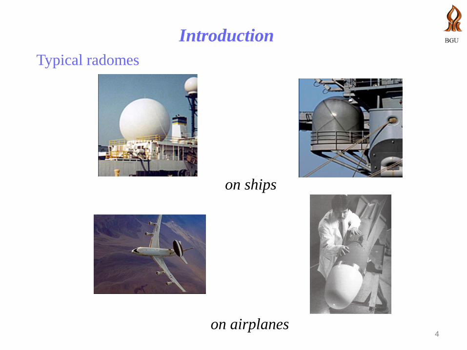
Introduction
4
on ships
Typical radomes
on airplanes

Introduction
Typical radomes
and on the ground
Solid laminate radome Inflatable radome Multipanel sandwich radome
Metal space frame radome Dielectric space frame radome
Introduction
6
Radomes are enclosures for antennas. Most radomes are hollow dielectric
shells although some contain perforated metallic layers or metallic
reinforcing structures. Radomes are used with large antennas on the earth’s
surface to reduce wind loading and to prevent accumulation of ice or snow.
These radomes usually have but not necessarily spherical contours. The
radomes affect :
Radiation pattern (sidelobe level)
Crosspol pattern
Power transmittance (transmission loss)
Antenna noise temperature
Boresight error
Boresight error slope
7
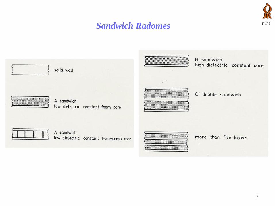
Sandwich Radomes
8
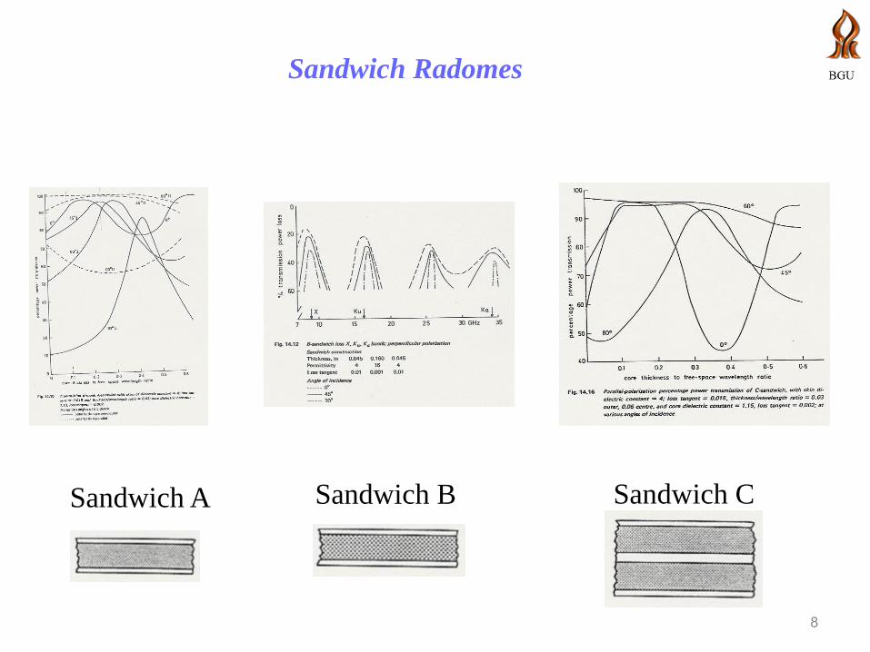
Sandwich Radomes
Sandwich A Sandwich B Sandwich C
9
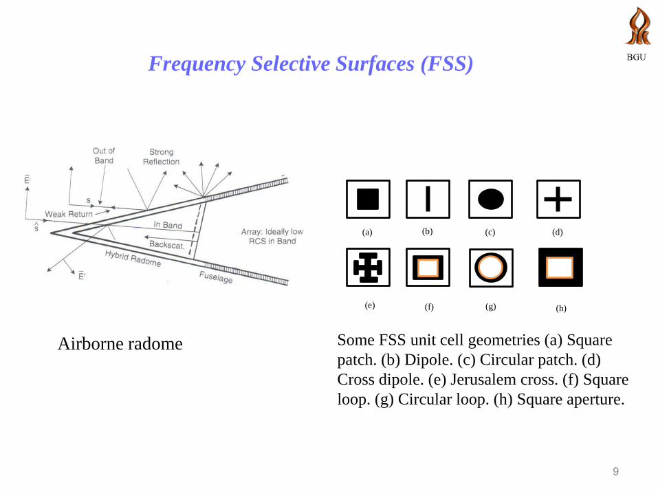
Frequency Selective Surfaces (FSS)
Airborne radome
(c)
(f) (g)
(a)
(e)
(b) (d)
(h)
Some FSS unit cell geometries (a) Square
patch. (b) Dipole. (c) Circular patch. (d)
Cross dipole. (e) Jerusalem cross. (f) Square
loop. (g) Circular loop. (h) Square aperture.
10
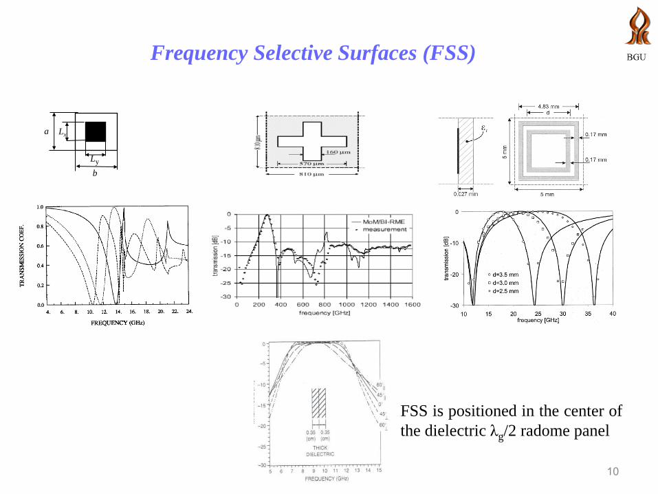
Frequency Selective Surfaces (FSS)
a Lx
Ly
b
FSS is positioned in the center of
the dielectric λg/2 radome panel

Airborne Radomes
z
Ώ
x
xc zc
L
D
antenn
a
2a
(x0,z0)
θ'
(x',z')
The cross section of an airborne radome based
on super-spheroids geometry profile.
Comparison of radiation patterns of MoM solution,
hybrid PO-MoM and antenna without radome for an
antenna aperture tilted 100. The length of the radome
is 10λ and 5λ in diameter. The antenna is circular
with 4λ in diameter. The radome thickness is 0.2 λ
and its dielectric constant εr=4
Airborne Radomes
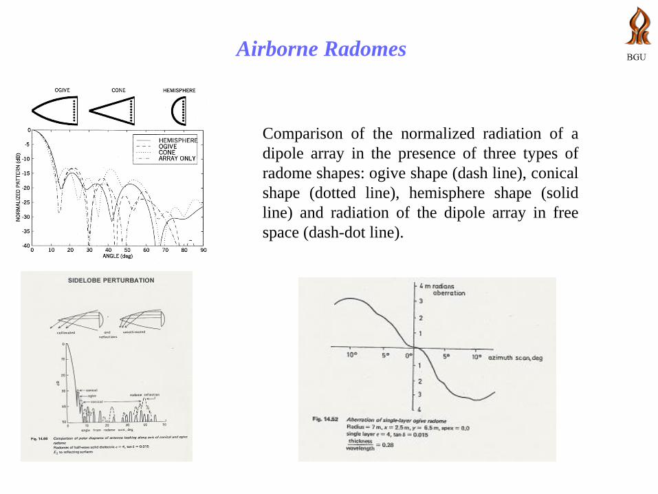
Comparison of the normalized radiation of a
dipole array in the presence of three types of
radome shapes: ogive shape (dash line), conical
shape (dotted line), hemisphere shape (solid
line) and radiation of the dipole array in free
space (dash-dot line).
Ground Based Radomes
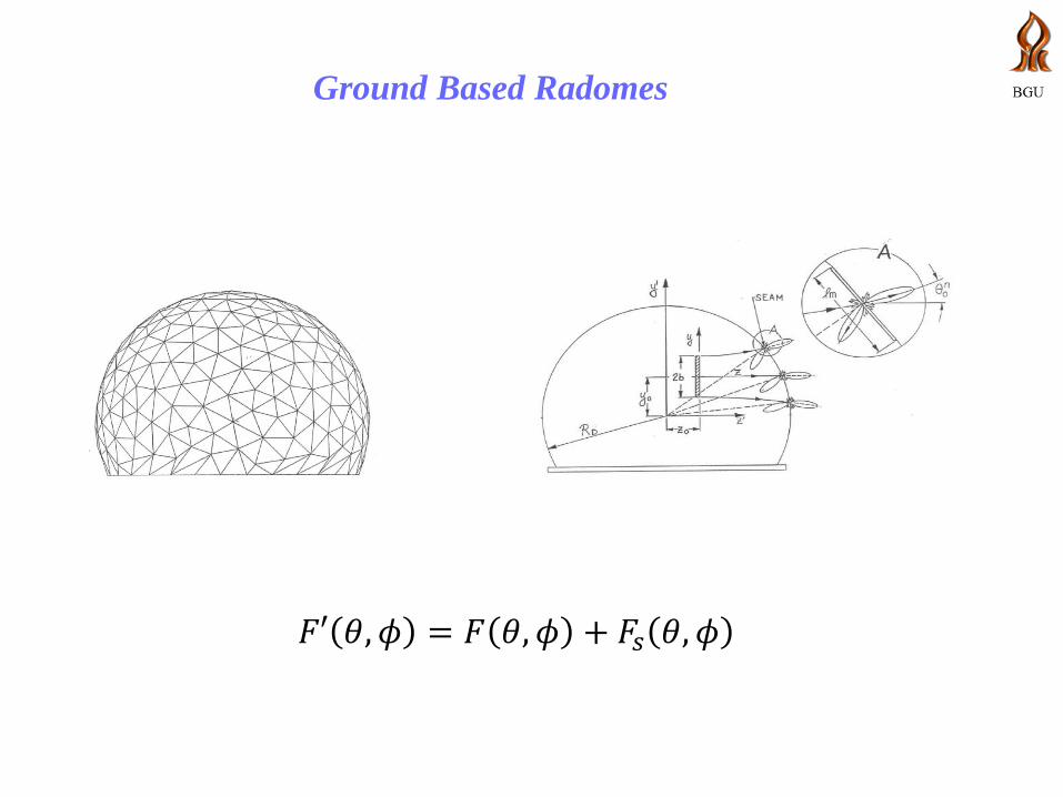
𝐹′ 𝜃, 𝜙 = 𝐹 𝜃, 𝜙 + 𝐹𝑠 𝜃, 𝜙
Ground Based Radomes
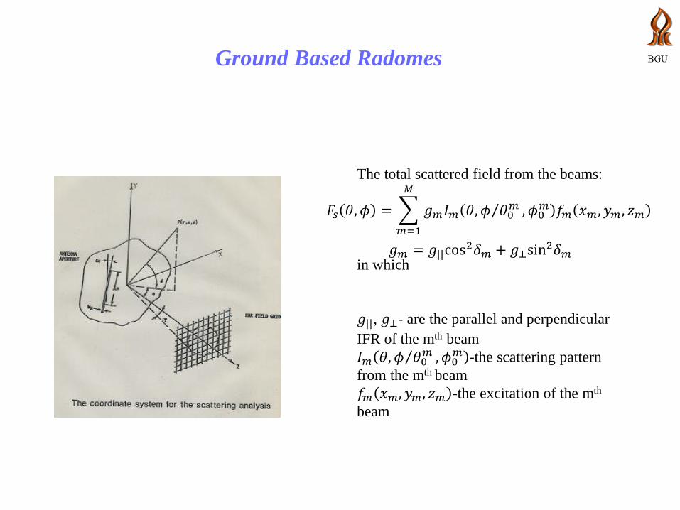
The total scattered field from the beams:
in which
𝑔||, 𝑔⊥- are the parallel and perpendicular
IFR of the mth beam
𝐼𝑚 𝜃, 𝜙 𝜃0𝑚 , 𝜙0
𝑚 -the scattering pattern
from the mth beam
𝑓𝑚 𝑥𝑚, 𝑦𝑚 , 𝑧𝑚 -the excitation of the mth
beam
𝐹𝑠 𝜃, 𝜙 = 𝑔𝑚𝐼𝑚 𝜃, 𝜙 𝜃0𝑚 , 𝜙0
𝑚 𝑓𝑚 𝑥𝑚, 𝑦𝑚 , 𝑧𝑚
𝑀
𝑚=1
𝑔𝑚 = 𝑔||cos2𝛿𝑚 + 𝑔⊥sin
2𝛿𝑚
Ground Based Radomes
Electromagnetic Design Considerations
• Panel optimization to reduce the transmission losses
• Computation of the scattering levels due to the seams
• Reduction of a single seam scattering (IFR)
• Optimization of the radome geometry to reduce its total
scattering effect
Ground Based Radomes
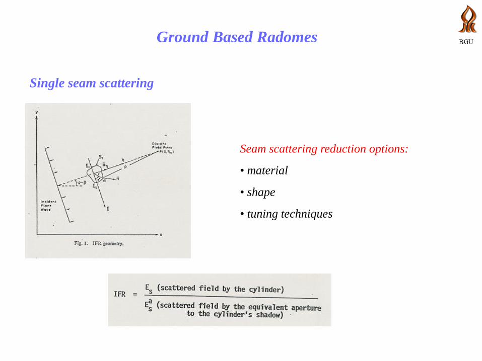
Single seam scattering
Seam scattering reduction options:
• material
• shape
• tuning techniques
Ground Based Radomes
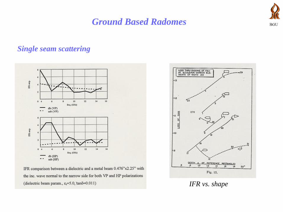
Single seam scattering
IFR vs. shape
Ground Based Radomes
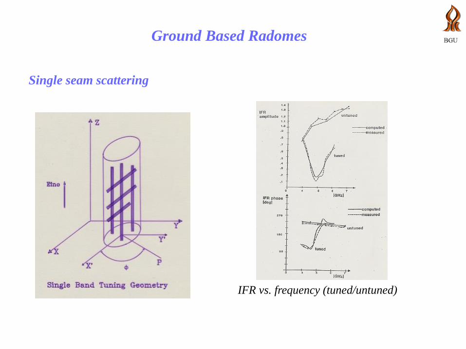
Single seam scattering
IFR vs. frequency (tuned/untuned)

Ground Based Radomes
Single seam scattering
Scattering pattern of a single seam (tuned/untuned)
amplitude (dB) phase (deg.)
(a) untuned dielectric beam
amplitude (dB) phase (deg.)
(b) tuned dielectric beam

Ground Based Radomes
Seam tuning importance
Ground Based Radomes
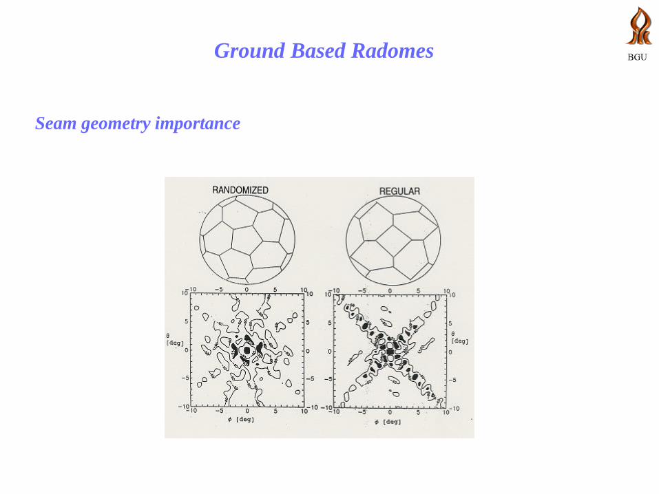
Seam geometry importance
Ground Based Radomes
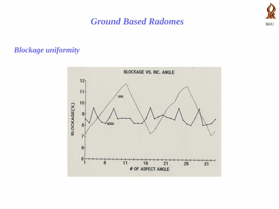
Blockage uniformity
Ground Based Radomes
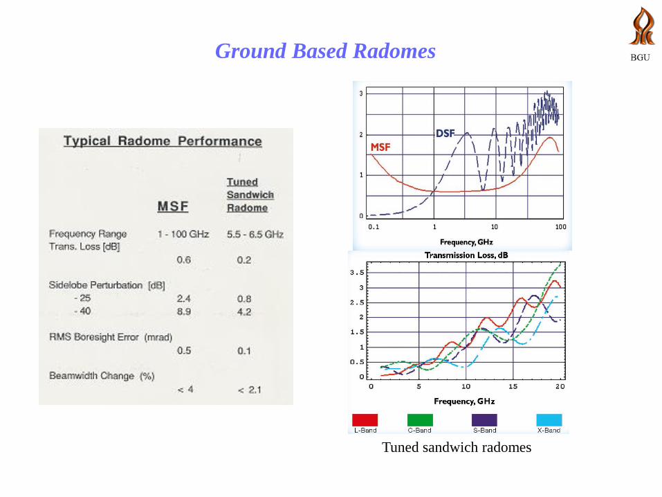
Tuned sandwich radomes
24
Concluding Remarks
Design principles of multilayered radomes have been presented
Various radome types and their performance have been discussed
Scattering analysis for space frame radomes have been presented