Embed Size (px)
Citation preview
1
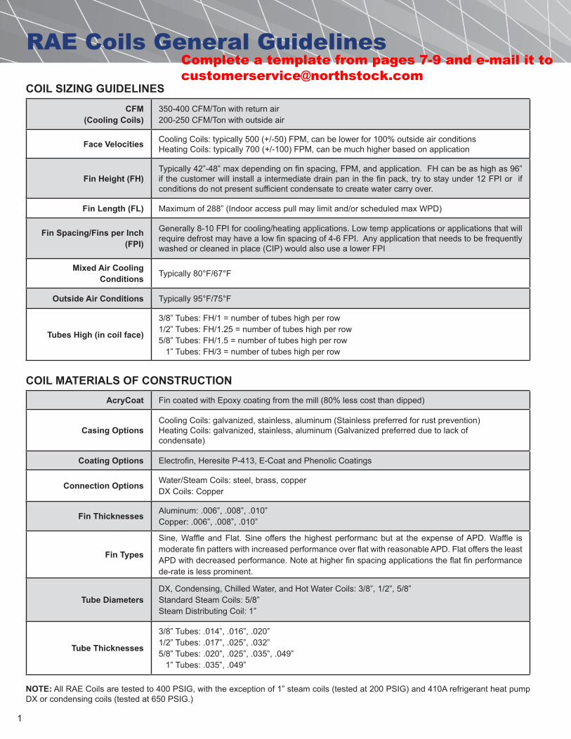
RAE Coils General Guidelines
COIL SIZING GUIDELINES
COIL MATERIALS OF CONSTRUCTION
CFM (Cooling Coils)
350-400 CFM/Ton with return air200-250 CFM/Ton with outside air
Face Velocities Cooling Coils: typically 500 (+/-50) FPM, can be lower for 100% outside air conditionsHeating Coils: typically 700 (+/-100) FPM, can be much higher based on application
Fin Height (FH)Typically 42”-48” max depending on fin spacing, FPM, and application. FH can be as high as 96” if the customer will install a intermediate drain pan in the fin pack, try to stay under 12 FPI or if conditions do not present sufficient condensate to create water carry over.
Fin Length (FL) Maximum of 288” (Indoor access pull may limit and/or scheduled max WPD)
Fin Spacing/Fins per Inch (FPI)
Generally 8-10 FPI for cooling/heating applications. Low temp applications or applications that will require defrost may have a low fin spacing of 4-6 FPI. Any application that needs to be frequently washed or cleaned in place (CIP) would also use a lower FPI
Mixed Air Cooling Conditions Typically 80°F/67°F
Outside Air Conditions Typically 95°F/75°F
Tubes High (in coil face)
3/8” Tubes: FH/1 = number of tubes high per row1/2” Tubes: FH/1.25 = number of tubes high per row5/8” Tubes: FH/1.5 = number of tubes high per row 1” Tubes: FH/3 = number of tubes high per row
AcryCoat Fin coated with Epoxy coating from the mill (80% less cost than dipped)
Casing OptionsCooling Coils: galvanized, stainless, aluminum (Stainless preferred for rust prevention)Heating Coils: galvanized, stainless, aluminum (Galvanized preferred due to lack of condensate)
Coating Options Electrofin, Heresite P-413, E-Coat and Phenolic Coatings
Connection Options Water/Steam Coils: steel, brass, copperDX Coils: Copper
Fin Thicknesses Aluminum: .006”, .008”, .010”Copper: .006”, .008”, .010”
Fin Types
Sine, Waffle and Flat. Sine offers the highest performanc but at the expense of APD. Waffle is moderate fin patters with increased performance over flat with reasonable APD. Flat offers the least APD with decreased performance. Note at higher fin spacing applications the flat fin performance de-rate is less prominent.
Tube DiametersDX, Condensing, Chilled Water, and Hot Water Coils: 3/8”, 1/2”, 5/8”Standard Steam Coils: 5/8”Steam Distributing Coil: 1”
Tube Thicknesses
3/8” Tubes: .014”, .016”, .020”1/2” Tubes: .017”, .025”, .032”5/8” Tubes: .020”, .025”, .035”, .049” 1” Tubes: .035”, .049”
NOTE: All RAE Coils are tested to 400 PSIG, with the exception of 1” steam coils (tested at 200 PSIG) and 410A refrigerant heat pump DX or condensing coils (tested at 650 PSIG.)
Complete a template from pages 7-9 and e-mail it to [email protected]
2
RAE Coils General Guidelines
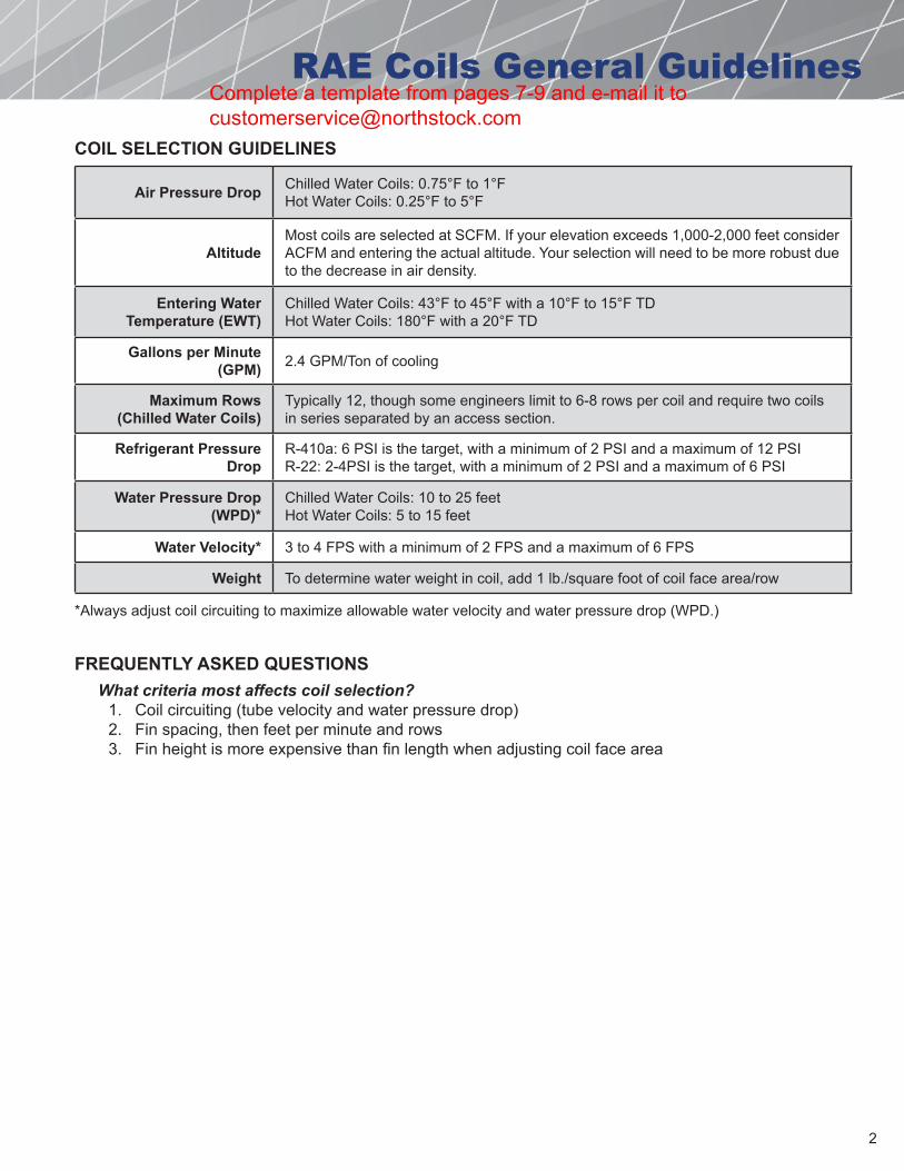
COIL SELECTION GUIDELINES
Air Pressure Drop Chilled Water Coils: 0.75°F to 1°FHot Water Coils: 0.25°F to 5°F
AltitudeMost coils are selected at SCFM. If your elevation exceeds 1,000-2,000 feet consider ACFM and entering the actual altitude. Your selection will need to be more robust due to the decrease in air density.
Entering Water Temperature (EWT)
Chilled Water Coils: 43°F to 45°F with a 10°F to 15°F TDHot Water Coils: 180°F with a 20°F TD
Gallons per Minute (GPM) 2.4 GPM/Ton of cooling
Maximum Rows (Chilled Water Coils)
Typically 12, though some engineers limit to 6-8 rows per coil and require two coils in series separated by an access section.
Refrigerant Pressure Drop
R-410a: 6 PSI is the target, with a minimum of 2 PSI and a maximum of 12 PSIR-22: 2-4PSI is the target, with a minimum of 2 PSI and a maximum of 6 PSI
Water Pressure Drop (WPD)*
Chilled Water Coils: 10 to 25 feetHot Water Coils: 5 to 15 feet
Water Velocity* 3 to 4 FPS with a minimum of 2 FPS and a maximum of 6 FPS
Weight To determine water weight in coil, add 1 lb./square foot of coil face area/row
*Always adjust coil circuiting to maximize allowable water velocity and water pressure drop (WPD.)
FREQUENTLY ASKED QUESTIONSWhat criteria most affects coil selection?
1. Coil circuiting (tube velocity and water pressure drop)2. Fin spacing, then feet per minute and rows3. Fin height is more expensive than fin length when adjusting coil face area
Complete a template from pages 7-9 and e-mail it to [email protected]
3
Typical Coil Circuiting
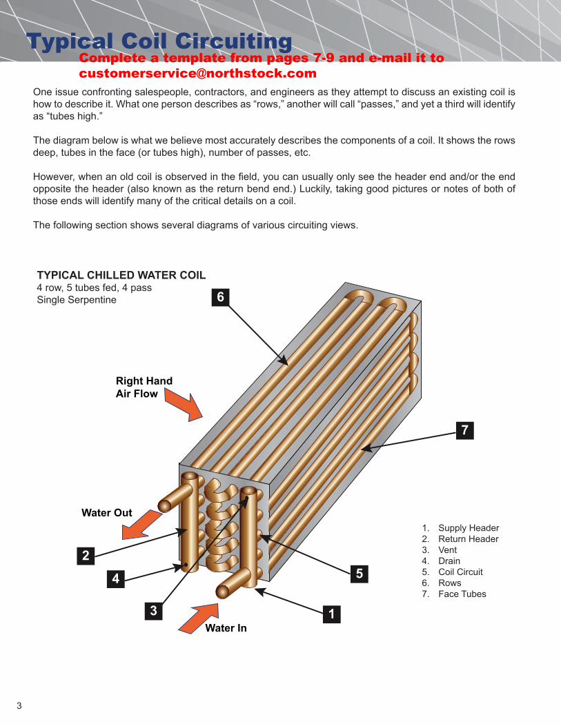
One issue confronting salespeople, contractors, and engineers as they attempt to discuss an existing coil is how to describe it. What one person describes as “rows,” another will call “passes,” and yet a third will identify as “tubes high.”
The diagram below is what we believe most accurately describes the components of a coil. It shows the rows deep, tubes in the face (or tubes high), number of passes, etc.
However, when an old coil is observed in the field, you can usually only see the header end and/or the end opposite the header (also known as the return bend end.) Luckily, taking good pictures or notes of both of those ends will identify many of the critical details on a coil.
The following section shows several diagrams of various circuiting views.
6
7
24
3 1
5
Water In
Water Out
Right HandAir Flow
TYPICAL CHILLED WATER COIL4 row, 5 tubes fed, 4 passSingle Serpentine
1. Supply Header2. Return Header3. Vent4. Drain5. Coil Circuit6. Rows7. Face Tubes
Complete a template from pages 7-9 and e-mail it to [email protected]
4
Typical Coil Circuiting
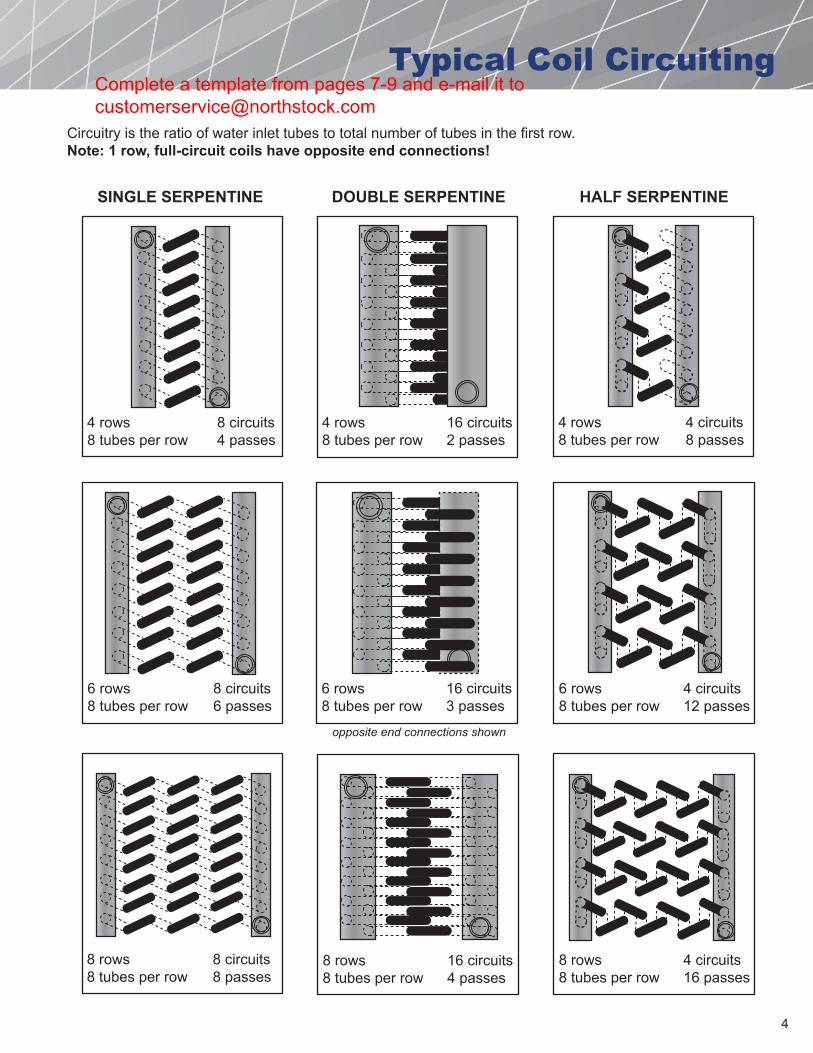
4 rows8 tubes per row
8 circuits4 passes
4 rows8 tubes per row
16 circuits2 passes
4 rows8 tubes per row
4 circuits8 passes
6 rows8 tubes per row
8 circuits6 passes
8 rows8 tubes per row
8 circuits8 passes
6 rows8 tubes per row
16 circuits3 passes
8 rows8 tubes per row
16 circuits4 passes
6 rows8 tubes per row
4 circuits12 passes
8 rows8 tubes per row
4 circuits16 passes
SINGLE SERPENTINE DOUBLE SERPENTINE HALF SERPENTINE
Circuitry is the ratio of water inlet tubes to total number of tubes in the first row.Note: 1 row, full-circuit coils have opposite end connections!
opposite end connections shown
Complete a template from pages 7-9 and e-mail it to [email protected]
5
Typical Coil Circuiting
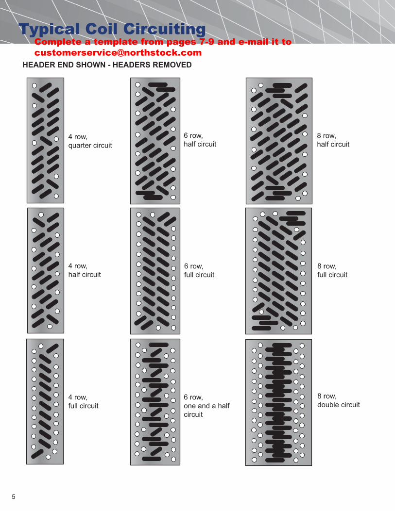
4 row,quarter circuit
4 row,half circuit
4 row,full circuit
6 row,half circuit
6 row,full circuit
6 row,one and a halfcircuit
8 row,half circuit
8 row,full circuit
8 row,double circuit
HEADER END SHOWN - HEADERS REMOVED
Complete a template from pages 7-9 and e-mail it to [email protected]
6
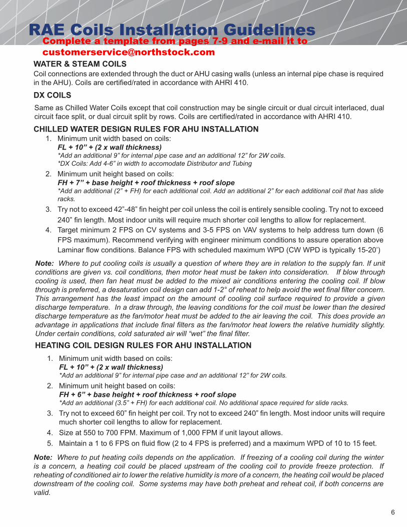
RAE Coils Installation Guidelines
WATER & STEAM COILS
1. Minimum unit width based on coils:FL + 10” + (2 x wall thickness)*Add an additional 9” for internal pipe case and an additional 12” for 2W coils.*DX Coils: Add 4-6” in width to accomodate Distributor and Tubing
2. Minimum unit height based on coils:FH + 7” + base height + roof thickness + roof slope*Add an additional (2” + FH) for each additional coil. Add an additional 2” for each additional coil that has slideracks.
3. Try not to exceed 42”-48” fin height per coil unless the coil is entirely sensible cooling. Try not to exceed240” fin length. Most indoor units will require much shorter coil lengths to allow for replacement.
4. Target minimum 2 FPS on CV systems and 3-5 FPS on VAV systems to help address turn down (6FPS maximum). Recommend verifying with engineer minimum conditions to assure operation aboveLaminar flow conditions. Balance FPS with scheduled maximum WPD (CW WPD is typically 15-20’)
Note: Where to put heating coils depends on the application. If freezing of a cooling coil during the winter is a concern, a heating coil could be placed upstream of the cooling coil to provide freeze protection. If reheating of conditioned air to lower the relative humidity is more of a concern, the heating coil would be placed downstream of the cooling coil. Some systems may have both preheat and reheat coil, if both concerns are valid.
Same as Chilled Water Coils except that coil construction may be single circuit or dual circuit interlaced, dual circuit face split, or dual circuit split by rows. Coils are certified/rated in accordance with AHRI 410.
Note: Where to put cooling coils is usually a question of where they are in relation to the supply fan. If unit conditions are given vs. coil conditions, then motor heat must be taken into consideration. If blow through cooling is used, then fan heat must be added to the mixed air conditions entering the cooling coil. If blow through is preferred, a desaturation coil design can add 1-2° of reheat to help avoid the wet final filter concern. This arrangement has the least impact on the amount of cooling coil surface required to provide a given discharge temperature. In a draw through, the leaving conditions for the coil must be lower than the desired discharge temperature as the fan/motor heat must be added to the air leaving the coil. This does provide an advantage in applications that include final filters as the fan/motor heat lowers the relative humidity slightly. Under certain conditions, cold saturated air will “wet” the final filter.
Coil connections are extended through the duct or AHU casing walls (unless an internal pipe chase is required in the AHU). Coils are certified/rated in accordance with AHRI 410.
DX COILS
CHILLED WATER DESIGN RULES FOR AHU INSTALLATION
HEATING COIL DESIGN RULES FOR AHU INSTALLATION1. Minimum unit width based on coils:
FL + 10” + (2 x wall thickness)*Add an additional 9” for internal pipe case and an additional 12” for 2W coils.
2. Minimum unit height based on coils:FH + 6” + base height + roof thickness + roof slope*Add an additional (3.5” + FH) for each additional coil. No additional space required for slide racks.
3. Try not to exceed 60” fin height per coil. Try not to exceed 240” fin length. Most indoor units will requiremuch shorter coil lengths to allow for replacement.
4. Size at 550 to 700 FPM. Maximum of 1,000 FPM if unit layout allows.5. Maintain a 1 to 6 FPS on fluid flow (2 to 4 FPS is preferred) and a maximum WPD of 10 to 15 feet.
Complete a template from pages 7-9 and e-mail it to [email protected]
7
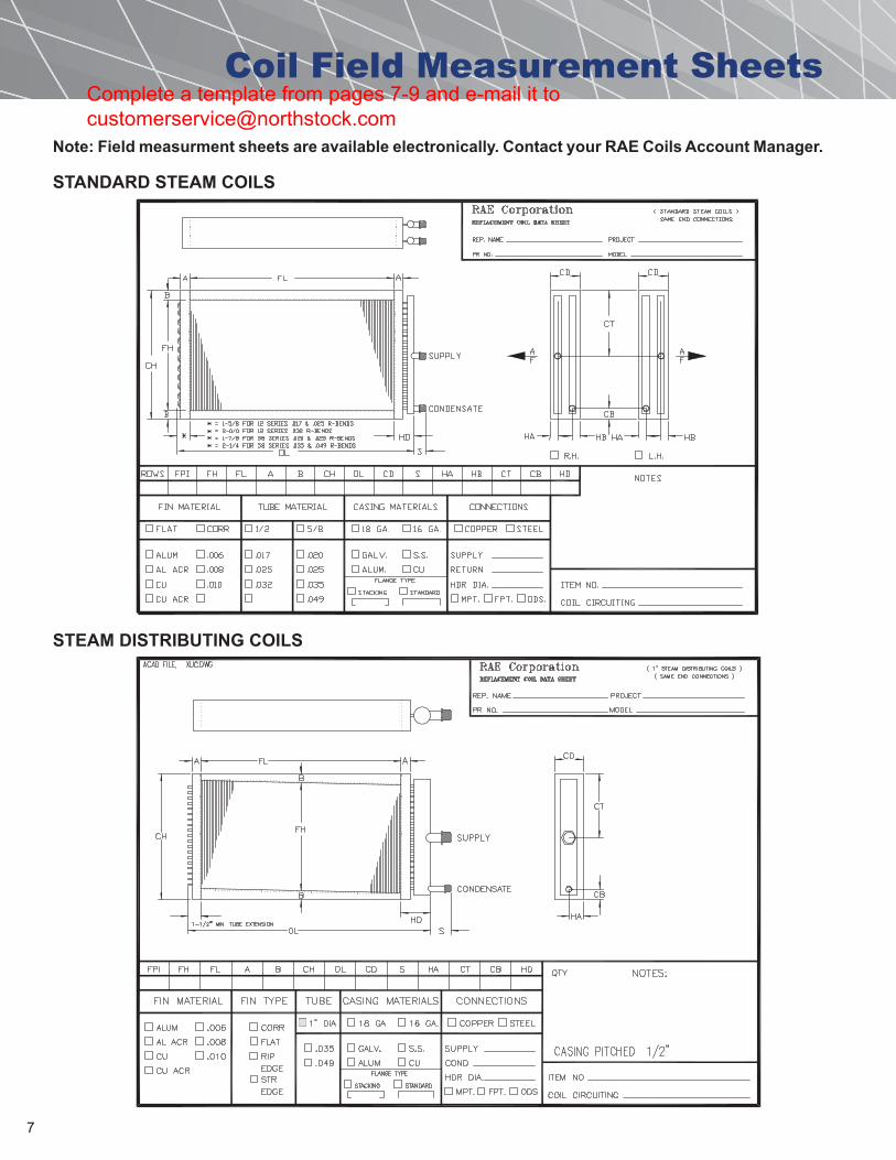
Coil Field Measurement Sheets
Note: Field measurment sheets are available electronically. Contact your RAE Coils Account Manager.
STANDARD STEAM COILS
STEAM DISTRIBUTING COILS
Complete a template from pages 7-9 and e-mail it to [email protected]
8
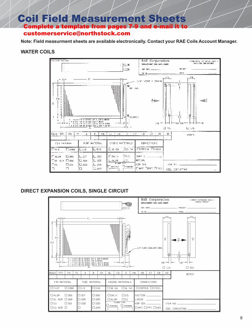
Coil Field Measurement Sheets
Note: Field measurment sheets are available electronically. Contact your RAE Coils Account Manager.
WATER COILS
DIRECT EXPANSION COILS, SINGLE CIRCUIT
Complete a template from pages 7-9 and e-mail it to [email protected]

9
Coil Field Measurement Sheets
Note: Field measurment sheets are available electronically. Contact your RAE Coils Account Manager.
DIRECT EXPANSION COILS, DUAL CIRCUIT INTERLACED
Complete a template from pages 7-9 and e-mail it to [email protected]