Embed Size (px)
Citation preview

Indian Journal of Radio & Space Physics Vol. 28, August 1999, pp. 159-164
Rain-induced cross-polarization at cm and mm wavelengths: A comparison of existing models
A 0 Sarma
R & T Unit fo r Navigational Electronics, Osmani a Uni versity, Hyderabad 500007
and
M V S N Prasad
Radio & Atmospheric Sciences Di vision, National Physical Laboratory, New Delhi 11 00 12
Received 25 May 1998; revised received 8 December 1998; accepted 15 April 1999
The performance and reli ability of a dual polarized microwave line-of-sight link operating above 10 GHz gets degraded by rain . Among the vari ous degrad ing effects, the important ones are attenuation and depolarization. In this paper, depo lari zatio n effect of rain has been dealt at length. Three models which can be used to estimate depo larization have been co mpared. T he cross talk levels are estimated for various dropsize distributions, canting angles and vert ical and hori zontal polari zations. T hese results indicate that the performance of dual polari zed links will be degraded to unacceptable levels during heavy rain.
1 Introduction Recent advances in telecommunications, remote
sensing and military systems require ever increasing use of hi gher frequency bands such as microwaves and millimet re waves . The status of microwave frequency bands fo r communicati on in Indi a is reported e lsewhere l
.
When an e lectromagnetic wave propagates t!l.ough a rain medi um, it suffe rs scattering, absorpti on, sc intill ati on and depolari zati on. In thi s paper, we concentrate onl y on depolari zati on effec ts. To increase c hanne l capac ity without increasing bandwidth , orthogonal po lari zati on (linear or circular) may be independently used for transmi ss ion at the same frequency over the same path . However, frequency reuse may be impaired by the poss ibitity that, in propagating through the atmosphere, some of the energy transmjtted in one po larization can be transferred to the orthogonal polarization state causing interference between the two channels. Thi s phenomenon , usuall y referred to as crosspolari zation, may be caused both by rain and hydro meteors and may also occur during periods of multi path propagati on. In addition to thi s, crosspolari zati on may ari se due to the characteri sti cs of the antenna sys tems at each terminal, and this component will then exist as base level s ignal. It is, therefore, necessary to develop a model, capable of predicting the behav iour of microwave and millimetre wave
systems in presence of rain . Because of the complex ity and random behaviour of the diffe rent factors involved in the phys ical process of rainfa ll , it is quite difficult to find a mode l which is simple and re liable. Three mode ls, name ly, (i) ITU-R (formerl y CCIR), ( ii ) S imple isolati on mode l(SIM) and (iii )
Oguchi and Hosoya (O-H)mode l, are examined here. The important parameters in volved in the mode ls are the shape of the raindrop, dropsize distribution and canting angle.
2 Theoretical background
Rain-induced cross-po lari zation is an important subj ect as it limits the effi c ient use of communication channels. Rain-induced cross-polarization is known to ari se from the non-spheric ity of the raindrops and canting with respect to the polarization plane. The polari zati on of a uniform plane wave refers to the time varying behaviour of e lectric fi e ld vector E at some fixed point in space. For a radio wave transmitted with a given polari zation, the cross-polar di scrimjnation(XPD) is the ratio, at the reception point, of the power received with the expected polari zation to the power received with orthogonal polarization. The XPD depends both on the characteri stics of the antennas and the propagation medium. This results to crosstalks in the case of signals transmi tted on two orthogonal polarizations.

160 INDIAN J RADIO & SPACE PHYS, AUGUST 1999
Differential phase shift and differential attenuation are important parameters in the estimation of crosstalk in microwave relay systems which use two orthogonal polarizations. These two quantities vary with the fundamental characteristics of the rain medium. The propagation constants, kh and kv of rain filled space for horizontally and vertically polarized incident waves, respectively , are given b/,
... (1)
where, n(ao) is the dropsize distribution and Ih and Iv are the fo rward scattering amplitudes of a drop with equivolumetric radius ao. Equivolumetric radius is the radius of a sphere with a volume equal to that of the oblate spheroidal drop.
The free space propagation constant, ko. should be added to kh or kv to obtain the real propagation constant of the medium. Assuming the rain to fa ll uniformly through path length L, the attenuations, Av and Ah in dB and the phase shifts ljIvand If/h in degrees for vertically and horizontally polarized incident waves , respectively, are given by
Ah.v =8 .868xim(kh.v )L dBlkm
180 ljIh.v = -x Re (kh.v )L deglkm
7r
and, hence, the differential attenuation differential phase shi ft are expressed as
dBlkm
dB/km
.. . (2)
... (3)
and
... (4)
... (5)
The parameters f).A and f).\jI for different dropsize distributions can be calculated by substituting the term n(ao) in Eg. ( I ) with the relevant dropsize distribution.
2.1 Prominent models There are several methods available for estimation
of rain-induced cross-polarization in microwave and millimetre wave bands. Here, we consider and compare three models, namely, ITU-R model, SIM and O-H model.
For most practical applications, relationship
between XPD and the co-polarized path attenuation
(CPA) is of utmost importance for prediction of XPD
based on attenuation statistics. In early applications
empirical relations between parameters were
employed and are still in use to some extent. However, it is now more common to use semi
empirical relations. A general relationship between
XPD and CPA has not yet been fully established, but long term measurements of CPA in the frequency
range between 3 and 37 GHz are in approximate agreement with a semi-empirical relationship3. The
ITU-R model and SIM give such re lationship between
XPD and CPA, whereas O-H model predicts XPD as
a function of dropsize distributi on. The parameters
used in ITU-R model and SllVI are : the frequency of
operation (f), the elevation angle of the slant path
( E.) and the tilt angle Ct)of the linearly polarized
electric field relative to horizontal. Raindrop
orientations are assumed to be Gaussian distributed
with mean canting angle < e > relative to horizontal
and standard deviat ion (as) of canting angle. The
shape distribution is assumed to be bimodal with a
fraction Fo being oblate spheroidal and the remaining
fraction (l-Fo) spherical. The mean orientation angle
of the raindrops and polarization of the radio wave can be combined, since it is only the orientation of
the electric field relative to the medium is important.
Therefore,
jlr- < e >1, Linearpolarization 8=
450 , Circular polarization
where, 8 is the parameter to characterize polarization, i.e. 8 = 0° for horizontal polarization, and 8 = 90° for
vertical polarization . One of the important differences between the three
models is that the canting angle was assumed to be
the same for all the raindrops (equi-oriented) in the O-H model, whereas canting angle was assumed to
follow a distribution with a mean and a standard deviation in the case of ITU-R model and SIM.
2.2 ITU-R model
The ITU-R model4 depends on the basic relationship hetween XPD and CPA.

SARMA & PRASAD: RAIN-INDUCED CROSS-POLARIZATION AT em & mm WAVELENGTHS 161
XPD = 30 log(!) - 10 log 0.5 [I - cos( 4o)e -{)OO24C/~ ]
- 40 log(cos£) +0.OO53cr~ - V 10g(CPA)
where,
V = {20, 23,
if 8$ 1$ 15
if 15$1$35
· .. (6)
· . . (7)
The exponential factor in am is included to avoid undefined values for horizontal and vertical polarizations. This parameter accounts for storm-tostorm variations of mean canting angles5
. Equation (7) applies only to cross-polarization induced by rain. For links in which the antennas do not have good cross-polarization isolations, Eq. (7) is found to be valid only in the XPD range where the antenna residuals do not contribute significantly to tlie crosspolar level .
2.3 Simple isolation model
Thi s model is an improvement over ITU-R model. The proposed si mple isolation modeI 5(SIM) is based on a ngorous modelling technique with no approximations of the type used in ITU-R model. This simple model results from curve fitting to rigorous calculations. The SIM permits prediction of XPD as a function of attenuation for any satellite link operating in 10-30 GHz band and is validated by satellite data. The SIM can be written in the following form
XPD = 9.5 + 17.310g (J) - 42 log (COS E)
-IOlog [0.5 (\-CoS (48 )e (-OOO24C1~))] +0.0053 a; -2010g (F:, )-1910g (CPA)
· .. (8)
with a;n=3°, ao:::::12° and Fo=0 .65 (correction factor) .
2.4 Oguehi and Hosoya model
In this model6, deformed raindrops are assumed to
be oblate spheroids, and the linear relationship between deformation and dropsize is assumed. That IS,
S = -(0.41/4.5)R + I
where, S is the ratio of the minor to the major axis and R the radius(mm) of the equivolumetric spherical raindrop. For a given scatter with finite canting angle, it has been shown2 that the crosstalk in horizontal (Xh)and vertical (Xv) transmitted signal is given by,
X h = 20 log 10 (1- g) tan 8, 1+ g tan 2 8,
g = exp [ i (kh - kv) L ]
. .. (9)
· .. (10)
· .. (11)
and kh and kv,are the propagation constants and are defined by
kh = ko + 27r f Ih (D) N (D) dD ko
kv = ko + 27r f Iv (D) N (D) dD ko
· . . (12)
· .. (13)
where, Av are the forward scattering amplitudes, N(D) dD is the drop size distribution in space, ko the free space propagation constant, L the propagation distance and 8, is the apparent canting angle.
As there are no ex isting data on the distribution of canting angles of raindrops at a point and also along a propagation path, the case of equi-oriented raindrops is considered for depolarization calculation. In view of this , the depolarization is calculated for a constant canting angle of 5°, 10°, and 20° taking a propagation path ·Iength of I km. The forward scattering amplitudes for a frequency range of 4-50 GHz have been taken from Oguchi and Hosoya for the calculation of crosstalk. Compared with other numerical models, this technique provides a stable algorithm which is able to handle highly distorted particles. The maximum acceptable level of crosspolarization factors is considered to be around -25 to -30 dB depending on the communication system2
. A system having an XPD of 30dB is better than the system having 25 dB .
3 Results and discussion
The ITU-R model estimates XPD for a given CPA in the frequency range of about 8-35 GHz and SIM
162 INDIAN J RADIO & SPACE PHYS, AUGUST 1999
estimates XPD for a frequency range of about 10-30 GHz. The O-H model is, on the other hand, applicable for a wide range of frequencies. For the calculation of CPA, nomogram given in ITU-R report4 is considered. As ITU-R model and SIM are based on CPA, no dropsize distribution information is necessary.
The ITU-R model and SIM are only approx imat ions to the actual calculations. The O- H model' s acc uracy is limited by the assumptions made in the ca lcul ati ons. Therefore, it would be more accurate and handy for the users if graphs are ava ilable showing the re lation between the rain rates (due to various distributions) and cross talk. Oguchi and Hosoy~ reported their results only for Laws and Parsons distribution; whereas in this paper, we report crosstalk ve rsus frequency results in the range of 4-50 GHz with a reso luti on of I GHz for other distributions also .
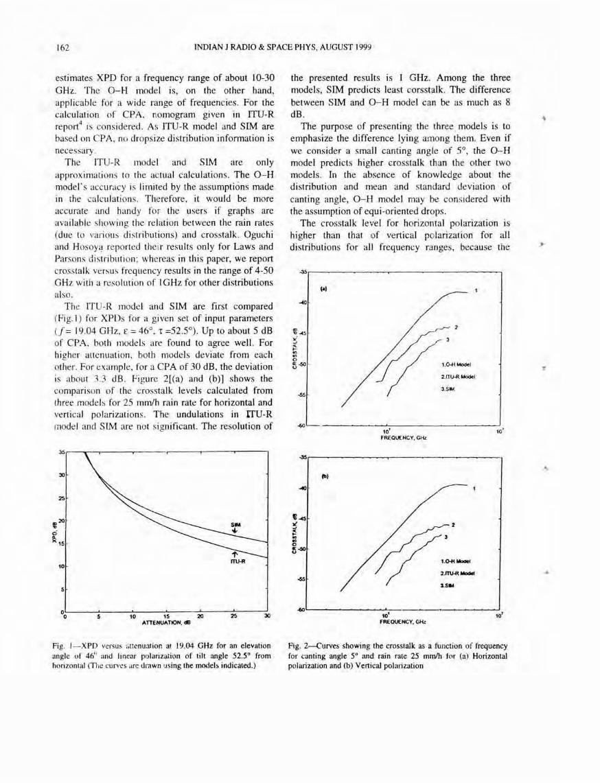
The TTU-R model and SIM are first compared (Fig. 1 ) for XPDs for a given set of input parameters (f = 19.04 GHz, £ = 46°, 1 =52.5°) . Up to about 5 dB of CPA, both models are found to agree well. For higher attenuati on, both models deviate from each other. For example, for a CPA of 30 dB , the deviation is about 3.3 dB . Figure 2[(a) and (b)] shows the compari son of the crosstalk levels calculated from th ree models for 25 mm/h rain rate for horizontal and vertica l polarizations. The undulations in rrU-R model and SIM are not significant. The resolution of
~r---'--~----'----- r-----,-------r------,
30
10
5
~L-----5~-----1~~-----~~~----~~--~30
ATTEHlIATION. dB
Fig. I- XPD versus <i ttenua.ion at 19.04 GHz for an elevation angle of 46" and linear polarization of tilt angle 52.5° from horizontal (The curves arc drawn using the models indicated.)
the presented results is 1 GHz. Among the three models, SIM predicts least corsstalk. The difference between SIM and O-H model can be as much as 8 dB.
The purpose of presenting the three . models is to emphasize the difference lying among them. Even if we consider a small canting angle of 5°, the O-H model predicts higher crosstalk than the other two models. In the absence of knowledge about the di stribution and mean and standard deviation of canting angle, O- H model may be considered with the assumption of equi-oriented drops.
The crosstalk leve l for horizontal po larization is higher than that of vertical polarization for all distributions for all frequency ranges, because the
~r-------------~--------------------,
Ca' /-
/2
f// I' / 1.0 .t/ModeI
! 2.1T1J.R Model
/ 3.5-.(
-40
10' 10' FREQUENCY. GHz
~
(III
-<to
~-45 tI' -' ~ .. .. 0 tj-40 0
~2
r-' // 1 .~_ / 2.mHt_
3.5IM
'--~~ ___ ~~---'-' -------10' 10'
FREQUENCY. C..Hz
Fig. 2--Curves showing the crosstalk as a function of frequency for canting angle 5° and rain rate 25 mmlh for (a) Horizontal polarization and (b) Vertical polarization

'"
SARMA & PRASAD: RAIN-INDUCED CROSS-POLARIZATION AT cm & mm WAVELENGTHS 163
scattering amplitude for horizontal polarization is higher than that for vertical polarization, since the electrical size of oblate spheroidal raindrops for vertical polarization is considered to be smaller than that for horizontal polarization. That is why crosstalk level at 50 GHz for horizontal polarization is about -38 dB and for vertical polarization it is -39.8 dB . The results presented in Figs 3-5 are due to O-H model.
Figure 3[(a) and (b)] presents crosstalk versus frequency for hori zontal and vertical polarizations and at canting angle of 10° and rain rate of 25 mmIh for four dropsize di stributions. The distributions taken are: Laws and Parsons (LP), log normal (LN);
-30
("
-35 3
.. ,,~
" oJ « ... ., ., 0 ~~5
10' 10' FREQU£NCY. CHz
.:0
.. , •
-3S 3
:2
C~
" oJ
t ., 0 ~~
10' FREQUENCY. CHz
Fig. 3--Curve~ showing the crosstalk as a function of frequency for canting angle 10° and rain rate 25 mmlh (Q.-H model) for (a) Horizontal polarization and (b) Vertical polarization
Joss thunderstorm (JT) and Marshal and Palmer (MP) . Up to about 30 GHz, the differences among various dropsize distribution are within about 4 dB . At higher frequencies, JT and LN distributions predict less crosstalk as compared to the other di stributions. These differences are due to . the variations in the respective dropsize distributions . For example, the main difference between the LN and LP rain-dropsize distributions will occur for the smaller raindrop diameters7
. At higher frequencies , the wavelength becomes comparable to drop diameter. In the case of LN distribution, the number of smaller drops per cubic meter is less as compared to LP distribution . Therefore, the depolarization is higher in
-25
Cal • 3
-30
2
':,35
" oJ « t; ., 0 5~
10' 10'
FREQU£NCY. CHz
-25
{til 1
• -30 ,
2
e-$ " oJ
t ., 0 ti~
10' 10' FRU1UENCY. CHz
Fig. 4-Same as in Fig.3, but for canting angle 20° for (a) Horizontal polarization and (b) Vertical polarization
164 INDIAN J RADIO & SPACE PHYS. AUGUST 1999
-10r--~-~---""""'---~--------,
{Iol
-1S
/ UP
2.JT
3.MI'
la' fREQUENCY, Gtlz
1 3
2
10'
-10r----~~~~.,_--.--~-
11>1
-IS
OISTRl8VnoHS
UP
2.JT
10' 10' fREQUENCY, 1:;Hz
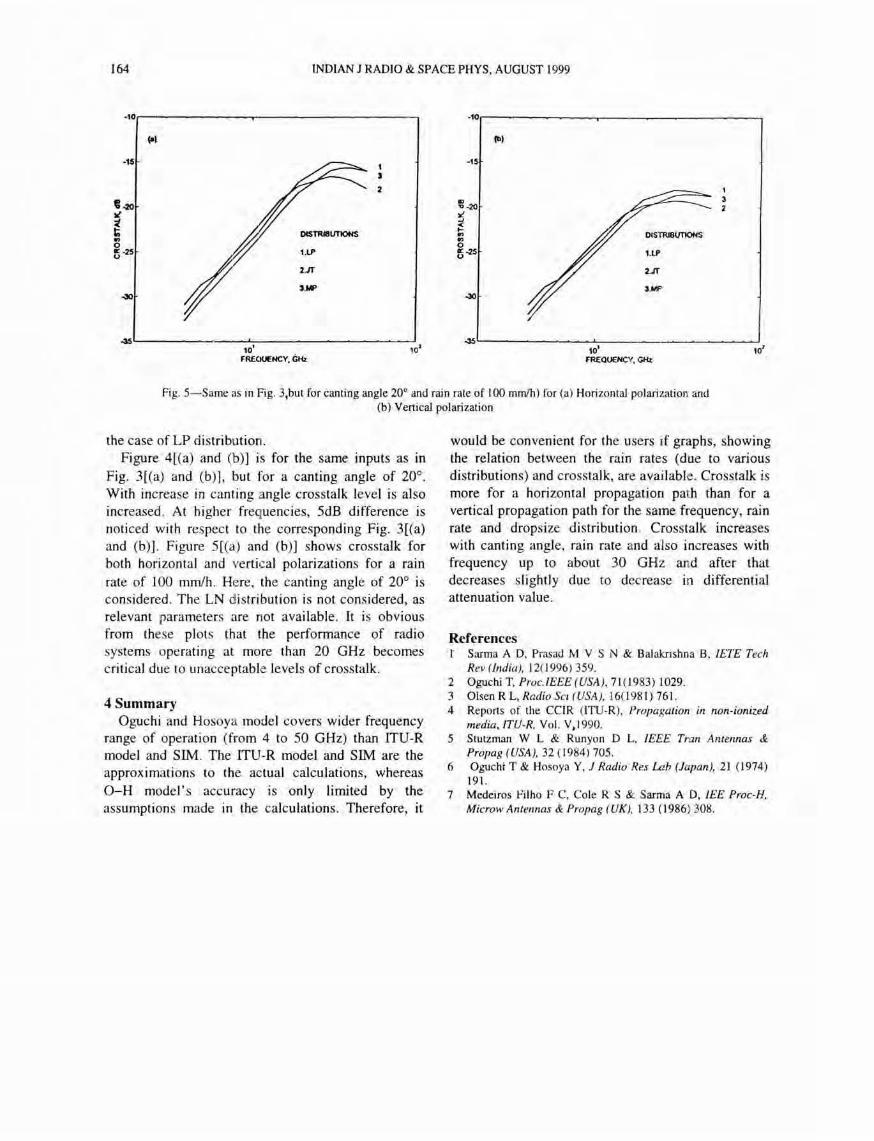
Fig. 5-Same as in Fig. 3,but for canting angle 20° and rain rate of 100 mm/h) for (a) Horizontal polarization and (b) Vertical polarization
the case of LP distribution. Figure 4[(a) and (b)] is for the same inputs as in
Fig. 3[(a) and (b)), but for a canting angle of 20°. With increase in canting angle crosstalk level is also increased. At higher frequencies, 5dB difference is noticed with respect to the corresponding Fig. 3[(a) and (b)]. Figure 5[(a) and (b)] shows crosstalk for both horizontal and vertical polarizations for a rain rate of 100 mm/h. Here, the canting angle of 20° is considered. The LN distribution is not considered, as relevant parameters are not available. It is obvious from these plots that the performance of radio systems operating at more than 20 GHz becomes critical due to unacceptable levels of crosstalk.
4 Summary Oguchi and Hosoya model covers wider frequency
range of operation (from 4 to 50 GHz) than ITU-R model and SIM. The ITU-R model and SIM are the approximations to the actual calculations, whereas O-H model's accuracy is only limited by the assumptions made in the calculations. Therefore, it
would be convenient for the users if graphs, showing the relation between the rain rates (due to various distributions) and crosstalk, are available. Crosstalk is more for a horizontal propagation path than for a vertical propagation path for the same frequency, rain rate and dropsize distribution . Crosstalk increases with canting angle, rain rate and also increases with frequency up to about 30 GHz and after that decreases slightly due to decrease in differential attenuation value.
References r Sarma A D. Prasad M V S N & Balakrishna B. IETE Tech
Rev (India), 12(1996) 359. 2 Oguchi T, Proc. IEEE(USA). 71(1983) 1029. 3 Olsen R L. Radio Sci (USA), 16(1 98 1) 761. 4 Reports of the CCIR (ITU-R). Propagation in non-ionized
media. ITU-R, Vol. V,1 990. 5 Stutzman W L & Runyon D L. IEEE Tran Antennas &
Propag (USA), 32 (1984) 705. 6 Ogucht T & Hosoya Y. J Radio' Res Lab (Japan), 21 (1974)
191. 7 Medeiros Filho F C. Cole R S & Sarma A D. lEE Proc-H.
MicrowAntennas & Propag (UK), 133 (1986) 308.


![6RPRV D 6HNHOHND 0XOWLPpGLD XPD QRYD … · 6rprv d 6hnhohnd 0xowlppgld xpd qryd rujdql]domr txh vh ghglfd qd surpromr rx sxeolfdomr gh surgxwrv vhuylorv frphufldlv h lpsuhvvmr h](https://img.pdfslide.net/doc/110x75/5bef764209d3f2112f8c6b00/6rprv-d-6hnhohnd-0xowlppgld-xpd-qryd-6rprv-d-6hnhohnd-0xowlppgld-xpd-qryd-rujdqldomr.jpg)


![$ SREUH]D H D GHVLJXDOGDGH XPD UHDOLGDGH …](https://img.pdfslide.net/doc/110x75/61bd3e4a61276e740b10ccd2/-sreuhd-h-d-ghvljxdogdgh-xpd-uhdolgdgh-.jpg)