Embed Size (px)
Citation preview

Rainbows, water droplets, and seeing—slowmotion analysis of experiments
in atmospheric optics
Michael Vollmer* and Klaus-Peter MöllmannMicrosystem and Optical Technologies, Brandenburg University of Applied Sciences,
Brandenburg, Germany
*Corresponding author: vollmer@fh‐brandenburg.de
Received 19 May 2011; revised 11 July 2011; accepted 11 July 2011;posted 12 July 2011 (Doc. ID 147897); published 19 August 2011
Many physics processes underlying phenomena in atmospheric optics happen on a rather short timescale such that neither the human eye nor video cameras are able to analyze the details. We reportapplications of high-speed imaging of laboratory experiments in atmospheric optics with subsequent slowmotion analysis. The potential to study respective transient effects is investigated in general and for afew phenomena in detail, in particular for rainbow scattering due to single oscillating droplets duringfree fall, and for light propagation effects through atmospheric paths with turbulences, leading, e.g., toscintillation of stars or shimmering of mirage images. © 2011 Optical Society of AmericaOCIS codes: 010.0010, 010.1290, 110.0115.
1. Introduction
Most experiments in atmospheric optics are usedto either visualize phenomena, such as rainbows,mirages or halos, observed in nature [1–4] or to quan-titatively measure various physical quantities as afunction of given parameters, such as, for example,radiance as a function of scattering angle. The rele-vant time scales are those defined by the kind of nat-ural phenomenon and they may differ from the usualobservation time in nature.
For example, rainbows may be observable for afew minutes, halos or mirages may last longer, some-times even up to hours. However, the underlyingphysical processes leading to these phenomena canhappen on a much shorter time scale. Rainbows, forexample, are phenomena where falling raindropscontribute to an observable phenomenon, the scatter-ing of sunlight into a specific angular range with re-spect to an observer’s eye. Hence, each individualdroplet only contributes for a certain time interval
to a certain color of scattered sunlight, which de-pends on the falling speed of the rain drops, theangular range of the observed rainbow colors, andthe distance of the contributing rain drops fromthe observer.
As an example, raindrops have terminal fall veloc-ities that depend on droplet size [5], ranging be-tween, e.g., 4–7m=s for droplets with diametersbetween 1 and 2mm and having about maximumspeeds up to around 9m=s for larger droplets. Letus assume 7m=s for 2mm droplets in a rain shower.The angular range that is seen as the rainbow has awidth of about 2° for a wavelength spectrum ofaround 200nm from blue to red within the visiblerange (λ ¼ 450–650nm). Although the rainbow doesnot represent pure spectral colors (see, e.g., [6]) weassume a green region of, say, 40nm spectral width,i.e., the green portion of the rainbow spectrum is seenin an angular range of about 0:4°.
The corresponding vertical distance of a rainbowseen in a distance of, for example, 1km is around7m. Raindrops with a velocity of 7m=s need just1s to fall through this region. This means that thiscolored portion of a rainbow, seen for several minutes
0003-6935/11/280F21-08$15.00/0© 2011 Optical Society of America
1 October 2011 / Vol. 50, No. 28 / APPLIED OPTICS F21

is of course due to successive 1s contributions frommany different droplets that fall through the respec-tive angular region. The shorter the distance fromobserver to droplet, the smaller the respective timeperiod. Observing rainbows in the spray of fountainsor garden sprinklers with distances on the order of10m easily reduces the respective time scales to1=100 s. Usually neither the human eye nor a cameraare able to resolve contributions from the individualdroplets. Rather a kind of glittering effect is per-ceived due to these changes.
Only very small raindrops are spherical. Largerdroplets can show rather pronounced deviationsfrom the spherical shape. In particular, in additionto just falling vertically due to gravity, rain dropsand water droplets can also oscillate in shape. Oscil-lation frequencies of falling liquid droplets depend onthe size of the droplets as well as viscosity of the li-quid. The first simplified theoretical explanationdates back to Lord Rayleigh [7] and meanwhile thebehavior of oscillating droplets has been extensivelystudied (e.g., [8–10]). Shape oscillation frequenciesrange, for example, from 100Hz for 2mm to 30Hzfor 5mm droplets. This means that respective peri-ods range between 10 to about 33ms. Similar to theshort time scales of observing individual raindropcontributions to rainbows, these droplet oscillationsare not visible with the naked eye and only barelyobservable with video cameras.
Deviations from spherical shape can lead to obser-vable optical phenomena. After shape oscillationshave died out due to frictional forces during the fallto the ground (experiments report that fall distancesof several meters are sufficient [11]), the dropletsgain their equilibrium shape, resembling somethinglike a thick pancake or maybe a hamburger bun.Droplets of such a shape are, for example, responsi-ble for the occurrence of supernumerary arcs close tothe top of primary rainbows [12,13]. Also, ellipticalshapes lead to different rainbow angles [13].
As a final example, the time scale associatedwith mirages and “seeing”, the twinkling of stars(e.g., [14,15]) shall be discussed. Both phenomenaare due to air turbulences within the atmosphere be-tween light source (usually scattered light of objectsfor mirages or star light for seeing) and the eye of anobserver or a detector. Because of the long light pathswithin the atmosphere with distances of many kilo-meters, air fluctuations with tiny changes in densityare present, resulting in small changes in refractiveindex. Because of the statistical nature of air fluctua-tions, the corresponding directional changes just leadto statistical deviations, occurring equally probablein all directions. As a result, images seen throughlong atmospheric paths do usually look fuzzy orshimmering and point sources like stars get a finitespatial extent of up to several arc seconds, i.e., muchlarger than the typical diffraction limit of telescopes.The time scale associated with these turbulences isusually of the order of milliseconds, again too fast todetect with the naked eye.
Modern experiments in atmospheric optics do uselight detectors, which have a much higher time reso-lution than the human eye. The first and most simpledetector with variable time resolution is the one of aphoto camera, one of the most often used instru-ments by observers of optical phenomena in nature.Photos are usually frozen images of a phenomenonwith the time scale being defined by the exposuretime. Unfortunately, the shorter the exposure time,the less light enters the camera lens. Therefore, quiteoften a compromise is needed between exposure timeand sufficient light for exposure. New developmentsin microsystem technologies within the last decadehave led to the development of quite inexpensive butvery sensitive camera detector systems [16]. Thesedo allow us to study many physics phenomena withhigh time resolution (e.g., [17,18]). It is therefore alogical step to also study atmospheric optics pro-cesses with such cameras and analyze the results inslow motion.
The present work summarizes the potential useof time-resolved photography in the field of atmo-spheric optics by discussing a number of possibleapplications. Then we report two easy but very in-structive time-resolved laboratory experiments inatmospheric optics in more detail:
– time evolution of a rainbow due to a single rain-drop in free fall;
– time-resolved analysis of deviation of lightwhile traveling through turbulent air.
We are convinced, that high-speed imaging ofatmospheric optics phenomena in the laboratorycan be successfully used to demonstrate importantprinciples of optics needed to understand the physicsunderlying these fascinating natural phenomena.Although most of these principles have been wellknown for a long time already, their study within thecontext of atmospheric optics can offer new ways oflooking at these phenomena. From a pedagogicalpoint of view, such laboratory experiments can helpto raise enthusiasm for observation and investiga-tion of the natural phenomena.
2. Potential Applications for High-speed Imaging inAtmospheric Optics
High-speed imaging is useful in atmospheric opticswhenever fast transient phenomena are studied.Examples are manifold and present for many differ-ent phenomena. Here, three respective laboratoryexperiments will be presented qualitatively beforeinvestigating two phenomena in more detail.
First, a number of halo phenomena require or-iented ice crystals. It is well known that, dependingon size and aspect ratio (see [3]), thin hexagonal platecrystals tend to orient their symmetry axis in thevertical direction, i.e., they become preferentiallyoriented while falling. However, not all axes are col-linear to others and already the axis of a single crys-tal tumbles around the equilibrium direction. One
F22 APPLIED OPTICS / Vol. 50, No. 28 / 1 October 2011

possibility to study these motions of ice crystals is touse model systems made of Styrofoam. Figure 1 de-picts a snapshot of an oriented and slight tumblingmodel crystal made of Styrofoam and falling froma height of about 3m. The orientation was quitestable and observations for longer periods revealedthat the axis tumbled around the vertical directionwith maximum angles of less than 20°, depending onfall conditions.
Second, oscillations of falling water droplets maybe easily studied in the laboratory by using a capil-lary inserted into a funnel and sealed with a rubberskin such that droplets can leak out. Depending onthe height of the liquid in the funnel (which definesthe hydrostatic pressure), the viscosity of the liquidand the inner diameter of the capillary, droplets ofvarious sizes may be formed, in our case typically be-tween 4 and 5mm whose initial phase of the fallswere observed with the high-speed camera. For con-trast reasons, the experiments described below wereperformed with a wine of deep red color.
Figure 2 shows a series of four snapshots of a fall-ing 5mm oscillating droplet (size of equivalent sphe-rical droplet). Brightness changes are due to theillumination, operated with the 50Hz line voltage.
The periods between the first and last of the fourimages was 1:5T ¼ 47ms, giving T ¼ 31:3ms andan oscillation frequency of about 32Hz. Consideringthe simplicity of the experiment, these resultscompare quite well with theoretical predictions andother measurements performed for water droplets asa function of size [10], which give around 43Hz for4mm water droplets and 31Hz for 5mm waterdroplets.
As a third qualitative example, illustrating thepotential of high-speed imaging, Fig. 3 shows twoimages of artificial lightning. An electric arc wasgenerated using a Wimshurst machine. Althoughimages were recorded with as many as 60 000 framesper second, it was not possible to measure the exactduration of the arcs. Rather, it was estimated to beless than about 20 μs as was expected from studiesfrom natural lightning [19]. However, even for inte-gration times of only 1=20; 000 s, it was possible torecord spectrally resolved images of individual arcdischarges.
Although the available equipment simplifies theanalysis of sparks experiments with artificial light-ning with regard to older research on lightningspectra [19], there is one drawback: sparks are phe-nomena that only last for periods in themicrosecondstime range or less. Therefore, extremely high framerates and short exposure times are needed for stu-dies of transient effects. If, in addition, large imagessizes are desirable, the necessary cameras becomequite sophisticated and very expensive.
3. Time-resolved Evolution of Rainbows
The color changes of contributing raindrops to rain-bows in nature during their fall through the respec-tive angular range gives rise to glittering effects. Fora detailed investigation of respective transient ef-fects with high-speed imaging, it is easier to studythe equivalent rainbow scattering from a single indi-vidual droplet in free fall. Figure 4 depicts the experi-mental setup.
Water droplets of around 4 to 5mm in size areformed. They fall vertically and then (after a variable
Fig. 2. (Color online) Falling droplets (sizes about 5mm) from a faucet oscillate between hamburger bun and cigar like shapes. Theperiods between the first and the other three images are 16ms, 31ms, and 47ms. Images were recorded with 4000 fps and an integrationtime of 1=5000 s.
Fig. 1. (Color online) Example of a Styrofoam hexagonal plate,which stays oriented during free fall. The two shadows are due tothe illumination.
1 October 2011 / Vol. 50, No. 28 / APPLIED OPTICS F23

distance of a few millimeters to several centimeters)enter a 150mW green laser beam (frequency doubledNd:YAG at λ ¼ 532nm), oriented horizontally with adiameter of about 2–3mm. If fully illuminated, a dro-plet scatters the light preferentially in the directionsof the rainbow angles, i.e., the scattered light of theprimary rainbow is expected along the edge of a conewith opening angle of about 42°, corresponding to ascattering angle of 138°. The high-speed camera isplaced within the horizontal plane such that it candetect sections of all such cones for a droplet whileit passes through the laser beam.
Figure 4/bottom depicts a side view of the arrange-ment. When entering the beam from the top suchthat only a lower part—in the figure, e.g., a third—of a droplet is illuminated (indicated by red), only theupper third of the rainbow scattered light cone isformed. When hitting the beam centrally, the middlethird of the cone is formed and when exiting the laserbeam such that just the upper third of a droplet isilluminated (indicated by red), only the lower thirdof the rainbow scattered light cone is formed.
Figure 5 illustrates the consequences of such a geo-metry for time increasing from left to right. The topfigure shows five instants in time with constant posi-tion of the green laser spot. The boundary of thedroplet in free falls is given by the outer line of thelarge circle. The inner line is at about 86% of its ra-dius. Hence, it marks the region of the droplet that
contributes to rainbow scattered light. In the left im-age, the droplet just touches the laser beam and onlya very small portion of the droplet can lead to rain-bow scattering. The respective angular range is indi-cated by the broken lines. While falling through thelaser beam, this angular range rotates and changessize until it finally drops to zero when the dropletcompletely leaves the laser beam.
The bottom figure resembles a projection planeperpendicular to the laser. The backscattered lightat the angle of the primary rainbow is concentratedaround a cone with angle of 42°. This cone cuts outa circle on the projection plane as indicated by thecircle. As demonstrated in the top figure, only se-lected angular ranges may contribute, dependingon the position of the droplet with respect to the laserbeam. Therefore, the respective angular ranges areindicated, too.
The camera (looking at an angle onto this plane)only detects a certain angular range as indicated,e.g., by the rectangle (broken lines), which meansthat we will only be able to detect part of the rainbowscattering for each single frame. For clarity, the rec-tangle only shows part of the detected image, whichhas quadratic shape (512 × 512 pixels).
Figure 6 depicts a series of six snapshots of indivi-dual cone sections contributing to rainbow scatteringtoward the camera, recorded with integration timesof 1=1000 s and a frame rate of 1000 frames persecond. The total fall time through the laser wasabout 32ms, i.e., rainbow scattering was detectedon 32 images. Figure 6 nicely visualizes the transient
Fig. 4. (Color online) Experimental setup for studying timeevolution of rainbow scattering of single droplets as seen fromtop (top) and from the side (bottom).Fig. 3. (Color online) Artificial lightning, i.e., an arc, observed
without (right) and another one observed through (left) a diffrac-tion grating using 20; 000 fps and shutter open. The spectral linescorrespond to emission lines mostly of N, O, Nþ, Oþ, and some ofN2, O2, N2
þ, and a few other species.
F24 APPLIED OPTICS / Vol. 50, No. 28 / 1 October 2011

Fig. 6. (Color online) Six snapshots (in 5ms intervals) of rainbow scattering contributions of a single droplet as function of position,i.e., falling time, recorded with 1000 fps, integration time of 1=1000 s.
Fig. 5. (Color online) Scheme for visualizing the successive rainbow scattering contributions while looking parallel to the green laserbeam. Top: While a large droplet is in free fall (from left to right), it has partial overlap with the laser beam. The broken lines indicateangular regions contributing to rainbow scattering. Bottom: If fully illuminated, the rainbow scattered light cone cuts out a circular shapeon a projection screen (corresponding to 42° angular distance from center). The broken lines, which rotate from left to right, again indicatethe angular regions where scattered light is present due to the respective overlap of laser and droplet. The broken line rectangle indicatesthe relevant part of the detected angular range of the camera. (More details, see text.)
1 October 2011 / Vol. 50, No. 28 / APPLIED OPTICS F25
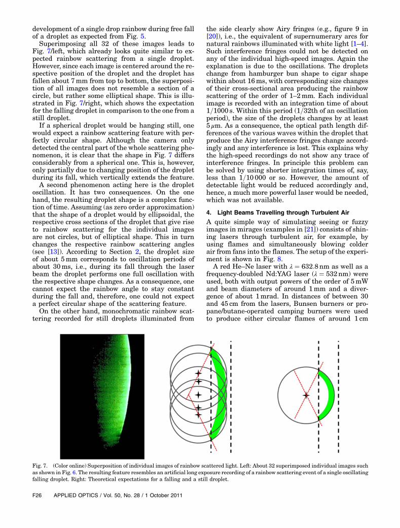
development of a single drop rainbow during free fallof a droplet as expected from Fig. 5.
Superimposing all 32 of these images leads toFig. 7/left, which already looks quite similar to ex-pected rainbow scattering from a single droplet.However, since each image is centered around the re-spective position of the droplet and the droplet hasfallen about 7mm from top to bottom, the superposi-tion of all images does not resemble a section of acircle, but rather some elliptical shape. This is illu-strated in Fig. 7/right, which shows the expectationfor the falling droplet in comparison to the one from astill droplet.
If a spherical droplet would be hanging still, onewould expect a rainbow scattering feature with per-fectly circular shape. Although the camera onlydetected the central part of the whole scattering phe-nomenon, it is clear that the shape in Fig. 7 differsconsiderably from a spherical one. This is, however,only partially due to changing position of the dropletduring its fall, which vertically extends the feature.
A second phenomenon acting here is the dropletoscillation. It has two consequences. On the onehand, the resulting droplet shape is a complex func-tion of time. Assuming (as zero order approximation)that the shape of a droplet would by ellipsoidal, therespective cross sections of the droplet that give riseto rainbow scattering for the individual imagesare not circles, but of elliptical shape. This in turnchanges the respective rainbow scattering angles(see [13]). According to Section 2, the droplet sizeof about 5mm corresponds to oscillation periods ofabout 30ms, i.e., during its fall through the laserbeam the droplet performs one full oscillation withthe respective shape changes. As a consequence, onecannot expect the rainbow angle to stay constantduring the fall and, therefore, one could not expecta perfect circular shape of the scattering feature.
On the other hand, monochromatic rainbow scat-tering recorded for still droplets illuminated from
the side clearly show Airy fringes (e.g., figure 9 in[20]), i.e., the equivalent of supernumerary arcs fornatural rainbows illuminated with white light [1–4].Such interference fringes could not be detected onany of the individual high-speed images. Again theexplanation is due to the oscillations. The dropletschange from hamburger bun shape to cigar shapewithin about 16ms, with corresponding size changesof their cross-sectional area producing the rainbowscattering of the order of 1–2mm. Each individualimage is recorded with an integration time of about1=1000 s. Within this period (1=32th of an oscillationperiod), the size of the droplets changes by at least5 μm. As a consequence, the optical path length dif-ferences of the various waves within the droplet thatproduce the Airy interference fringes change accord-ingly and any interference is lost. This explains whythe high-speed recordings do not show any trace ofinterference fringes. In principle this problem canbe solved by using shorter integration times of, say,less than 1=10 000 or so. However, the amount ofdetectable light would be reduced accordingly and,hence, a much more powerful laser would be needed,which was not available.
4. Light Beams Travelling through Turbulent Air
A quite simple way of simulating seeing or fuzzyimages in mirages (examples in [21]) consists of shin-ing lasers through turbulent air, for example, byusing flames and simultaneously blowing colderair from fans into the flames. The setup of the experi-ment is shown in Fig. 8.
A red He–Ne laser with λ ¼ 632:8nm as well as afrequency-doubled Nd:YAG laser (λ ¼ 532nm) wereused, both with output powers of the order of 5mWand beam diameters of around 1mm and a diver-gence of about 1mrad. In distances of between 30and 45 cm from the lasers, Bunsen burners or pro-pane/butane-operated camping burners were usedto produce either circular flames of around 1 cm
Fig. 7. (Color online) Superposition of individual images of rainbow scattered light. Left: About 32 superimposed individual images suchas shown in Fig. 6. The resulting feature resembles an artificial long exposure recording of a rainbow scattering event of a single oscillatingfalling droplet. Right: Theoretical expectations for a falling and a still droplet.
F26 APPLIED OPTICS / Vol. 50, No. 28 / 1 October 2011

diameter or rectangular flames of a few millimeterstimes 5 cm length. The laser beams were adjustedmore or less parallel and were finally directed ontowhite projection screens at a distance of 8m. Therethey had a lateral distance of about 24 cm. For stillroom temperature air, the visual laser beam spotdiameters on the screen were around 10mm (thevisual diameter depends somewhat on the eye, or,if using photos, on the detector sensitivity and expo-sure time; for quantitative measurements, a beamprofile measurement would be needed).
The first experiment consisted of taking regularphotos of the projection spots and varying the expo-sure time. For large exposure times such as 1 s,the beam spot in more or less still ambient air is al-ready a little bit larger than the one recorded with1=1000 s. Adding variations of the index of refractionof the air induced by passing the laser beam throughthe burner turbulent flames leads to an additionalwidening of the beam profile for a 1 s exposure time.The beam diameter can easily double its size. How-ever, for 1=1000 s exposure time the spot size withturbulence was very similar to the one without.
This qualitative experimental result from stillphotography is expected. It is well known that themagnitude of seeing, i.e., how much the angularspread is getting larger compared to the light passingthrough an unperturbed atmosphere, depends on
frequency and only small contributions are due tofrequencies above 1kHz [14]. Therefore, recordingsignals with exposure times of 1ms or less should notlead to pronounced angular spread of the light beamsdue to seeing.
In order to demonstrate this effect directly, the po-sition of the projection of the lasers on a white screenwas analyzed using our high-speed camera. Figure 9shows examples recorded for 4000 frames per secondand an integration time of 1=10 000 s (the latter wasoptimized such that the detectors were not fullysaturated by the intense radiation).
A series of eight images over a period of 2ms is de-picted. Obviously, the laser spot jumps back and forthin arbitrary directions. In the example of the image,it just jumped a distance of about 2:5 cm within 2ms.At the beginning and at the end, both spot diametersare about equal and resemble the one of the laser ifnot travelling through a turbulent atmosphere. Inte-grating the individual spot signals over 1 s will leadto much broader beam profiles similar to one of thelong-term exposures with regular photo cameras.
The lateral deflection of the order of 2 cm can beeasily understood if assuming reasonable tempera-ture fluctuation within the flame of, say, 50K in ad-jacent packages of air, which pass the laser beams.Of course, one can also find much longer periods oftime of the order of about 20–30ms, where the laserspot does not move very much, i.e., shows only smallangular spread.
These laser beam deflection experiments nicelydemonstrate that the typical time scale of air turbu-lences is of the order of 1ms. This behavior can alsoexplain why the method of lucky imaging (a stackingmethod for improving astronomy images of stars)[22] can be quite successful in eliminating, or betterin mitigating, the consequences of air turbulencesof seeing.
Fig. 9. (Color online) Eight snapshots of a section of the projection screen with the green laser spot, recorded with the high-speedNAC camera with 4000 fps and an integration time of 1=10; 000 s. The white grid (scale 3 cm) was superimposed for simplifying the ana-lysis. The laser beam statistically changes position with a time scale of about 1ms.
Fig. 8. (Color online) Experimental setup for air turbulenceexperiments with lasers.
1 October 2011 / Vol. 50, No. 28 / APPLIED OPTICS F27

5. Summary and Conclusions
Modern high-speed cameras do allow the investiga-tion of new, but also the reinvestigation of olderand well-known, experiments in atmospheric optics.Such studies can offer a lot of insight into the involvedphysical processes on short time scales. The potentialof such time-resolved analyses was qualitatively de-monstrated for laboratory experiments using fallinghexagonal crystal Styrofoam models, for shapechanges of falling droplets due to oscillations, as wellas for arc discharges. In addition, amore detailed ana-lysis was presented for the evolution of single dropletrainbow scattering during free fall as well as for theeffects of air turbulences on images, such as shimmer-ingmirages or scintillation of stars.Obviously there isa multitude of miscellaneous other atmospheric op-tics phenomena that may be visualized with high-speed imaging. Besides ultrafast phenomena, suchas lightning, which require extremely high framerates and short exposure times, all phenomena canbe studiedwithmedium-pricedor low-priced commer-cial cameras. Therefore, it can be expected that moreexperiments of this kind will be conducted in the fu-ture, hopefully raising more enthusiasm also for theobservation and investigation of these optical phe-nomena in nature.
References1. M. G. J. Minnaert, Light and Color in the Outdoors (Springer,
1993).2. R. Greenler, Rainbows, Halos, and Glories (Cambridge
University, 1980).3. D. K. Lynch and W. Livingston, Color and Light in Nature,
2nd ed (Cambridge University, 2001).4. M. Vollmer, “Optical phenomena in the atmosphere,”
in Springer Handbook of Lasers and Optics, F. Träger, ed.(Springer, 2007), pp. 1182–1203.
5. H. R. Pruppacher and J. D. Klett, Microphysics of Clouds andPrecipitation (Kluwer Academic, 1997).
6. R. L. Lee and A. Fraser, The Rainbow Bridge—Rainbows in Art, Myth, and Science (Penn State University,2001).
7. J. W. S. Rayleigh, “On the capillary phenomena of jets,” Proc.R. Soc. London 29, 71–97 (1879).
8. K. V. Beard, H. T. Ochs, and R. J. Kubesh, “Natural oscillationsof small raindrops,” Nature 342, 408–410 (1989).
9. J. Q. Feng and K. V. Beard, “A perturbation model of raindroposcillation characteristics with aerodynamic effects,” J. Atmos.Sci. 48, 1856–1868 (1991).
10. M. Szakáll, K. Diehl, S. K. Mitra, and S. Borrmann,“A wind tunnel study on the shape, oscillation and internalcirculation of large raindrops with sizes between 2.5 and7:5mm,” J. Atmos. Sci. 66, 755–765 (2009).
11. J. E. McDonald, “The shape of raindrops,” Sci. Am. 190,64–68 (1954).
12. A. B. Fraser, “Why can the supernumerary bows be seen in arain shower,” J. Opt. Soc. Am. 73, 1626–1628 (1983).
13. G. P. Können, “Appearance of supernumeraries of the second-ary rainbow in rain showers,” J. Opt. Soc. Am. A 4, 810–816(1987).
14. W. M. Protheroe, “Stellar scintillation,” Science 134,1593–1599 (1961).
15. E. Jakeman, G. Parry, E. R. Pike, and P. N. Pusey, “The twink-ling of stars,” Contemp Phys. 19, 127–145 (1978).
16. M. Vollmer and K.-P. Möllmann, “High speed—slow motion:technology of modern high speed cameras,” Phys. Educ. 46,191–202 (2011).
17. M. Vollmer and K.-P. Möllmann, “Exploding balloons,deformed balls, strange reflections, and breaking rods: slowmotion analysis of selected hands-on experiments,” Phys.Educ. 46, 472–485 (2011).
18. M. Vollmer and K.-P. Möllmann, “Ring falling into a chain: nomagic—just physics,” Phys. Teach. 49, 337–339 (2011).
19. M. A. Uman, Lightning (Dover, 1969).20. M. Vollmer and R. Tammer, “Laboratory experiments in
atmospheric optics,” Appl. Opt. 37, 1557–1568 (1998).21. M. Vollmer, “Mirrors in the air: mirages in nature and in the
laboratory,” Phys. Educ. 44, 165–174 (2009).22. D. L. Fried, “Probability of getting a lucky short-exposure
image through turbulence,” J. Opt. Soc. Am. 68, 1651–1658(1978).
F28 APPLIED OPTICS / Vol. 50, No. 28 / 1 October 2011