Embed Size (px)
Citation preview
2357(2006)1, 23-31
ASPHALT CARRIERS FROM THE KRALJEVICA SHIPYARD, CROATIA R. GRUBI©I∆UDC 629.543:629.5.017.1
Rajko GRUBI©I∆1 Asphalt Carriers fromKraljevica Shipyard, Croatia
Professional paper
This article is based on the materials presented by the experts from Kraljevica Shipyard at theannual meeting of the Croatian shipbuilding designers held in Kraljevica in October 2005. Asphalttanker Asphalt Seminole and her sister-ships are rather sophisticated vessels having a complexhull structure, cargo space and cargo survey and control equipment. Therefore, firstly the technicaldata of the already delivered asphalt tanker Asphalt Seminole are given and then, the very interestingdevelopment of her design in presented. Special emphasis is given to the design of the cargospace, to the stability survey of the intact ship at various loading cases as well as to the damagedship stability and floatability calculation in accordance with the pollution prevention regulations.Finally, a comparison of the present ship with various similar asphalt tankers in exploitation ismade.
Keywords: asphalt carriers, ship design, cargo spaces, stability.
Brodovi za prijevoz asfalta iz Brodogradiliπta KraljevicaStruËni rad
Ovaj Ëlanak se zasniva na materijalima koje su prikazali struËnjaci Brodogradiliπta Kraljevicana godiπnjem sastanku hrvatskih brodograevnih projektanata odræanom tijekom listopada uKraljevici. Asfaltni tankeri Asphalt Seminole i njegovi “blizanci” brodovi su velike sloæenosti sasloæenom strukturom trupa, teretnim prostorom kao i opremom za nadzor i upravljanje teretom.Stoga su najprije dani tehniËki podaci o nedavno isporuËenom asfaltnom tankeru Asphalt Semi-nole, a zatim je opisan vrlo zanimljiv razvoj njegovog projekta. Posebni je naglasak dan osnivanjuteretnog prostora, analizi stabiliteta neoπteÊenog broda za veliki broj stanja krcanja i proraËunustabiliteta i naplavljivosti oπteÊenog broda u skladu s propisima o spreËavanju zagaenja mora. Nakraju je dana usporedba prikazanog tankera s raznim sliËnim asfaltnim tankerima koji su veÊ ueksploataciji.
KljuËne rijeËi: brod za prijevoz asfalta, projektiranje broda, prostor za teret, stabilitet.
Authors’ address:1 University of Zagreb,
Faculty of Mechanical Engineeringand Naval ArchitectureIvana LuËiÊa 5, 10000 Zagreb,CroatiaE-mail: [email protected]
Received (Primljeno): 2005-10-18Accepted (PrihvaÊeno): 2006-01-19
1 Introduction
At the moment, the world fleet of asphalt (and similar cargo)carriers numbers 92 ships with 732 302 dwt, which makes 0.2%of the world tanker fleet. In comparison with the world tankerfleet, whose average age was 19.1 years at the beginning of 2005,the average age of the asphalt carriers is 17.3 years.
In the last 5 years 22 asphalt carriers with 143 298 dwt havebeen ordered: 6 ships in Japan, 5 in China, 3 in Turkey, 2 in Italyand in Bulgaria and 4 ships in Croatia with 36 800 dwt, whichmakes about 26% of the total number of ordered asphalt carriers.The above mentioned countries are also the biggest shipbuildersof these peculiar ships.
If the following particulars of the market are taken into ac-count:
• Increased demand for newbuilts• Increase of transport fees
• Need for the replacement of the old fleet• Relatively quick complementing of the free shipyard vacan-
cies• Change of the exchange rate EUR/USD (about 35%)• Increased prices of newbuilts (about 50% for asphalt carriers)
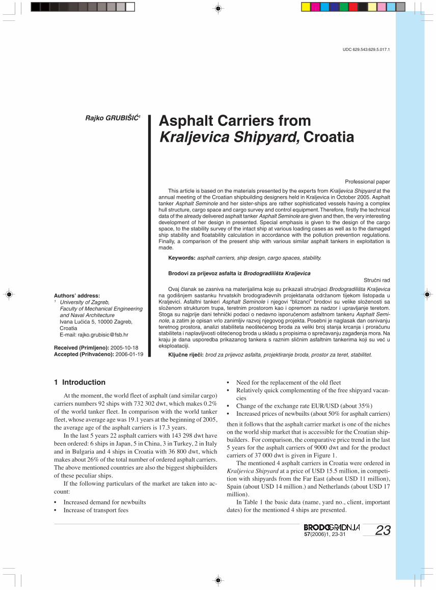
then it follows that the asphalt carrier market is one of the nicheson the world ship market that is accessible for the Croatian ship-builders. For comparison, the comparative price trend in the last5 years for the asphalt carriers of 9000 dwt and for the productcarriers of 37 000 dwt is given in Figure 1.
The mentioned 4 asphalt carriers in Croatia were ordered inKraljevica Shipyard at a price of USD 15.5 million, in competi-tion with shipyards from the Far East (about USD 11 million),Spain (about USD 14 million.) and Netherlands (about USD 17million).
In Table 1 the basic data (name, yard no., client, importantdates) for the mentioned 4 ships are presented.
24 57(2006)1, 23-31
R. GRUBI©I∆ ASPHALT CARRIERS FROM THE KRALJEVICA SHIPYARD, CROATIA
Figure 1 Price trends of asphalt carriers in comparison to prod-uct carriers
Slika 1 Kretanje cijena za tankere za prijevoz asfalta u usporedbis product carrierima
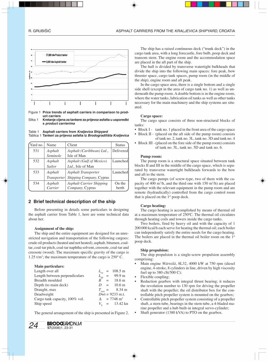
Table 1 Asphalt carriers from Kraljevica ShipyardTablica 1 Tankeri za prijevoz asfalta iz Brodogradiliπta Kraljevica
Yard no. Name Client Status
531 Asphalt Asphalt (Caribbean) Ltd., DeliveredSeminole Isle of Man
532 Asphalt Asphalt (Gulf of Mexico) LaunchedSailor Ltd., Isle of Man
533 Asphalt Asphalt Transporter LaunchedTransporter Shipping Company, Cyprus
534 Asphalt Asphalt Carrier Shipping On theCarrier Company, Cyprus berth
2 Brief technical description of the ship
Before presenting in details some particulars in designingthe asphalt carrier from Table 1, here are some technical dataabout her.
Assignment of the ship:
The ship and the entire equipment are designed for an unre-stricted navigation and transportation of the following cargoes:crude oil products (heated and not heated), asphalt, bitumen, coal-tar, coal-tar pitch, coal-tar naphtha solvent, creosote, coal-tar andcreosote (wood). The maximum specific gravity of the cargo is1.25 t/m3; the maximum temperature of the cargo is 250° C.
Main particulars:
Length over all Loa = 108.5 mLength between perpendiculars Lpp = 99.9 mBreadth moulded B = 18.6 mDepth (to main deck) D = 10.6 mDraught, max Tmax = 8.34 mDeadweight Dwt = 9233 m.t.Cargo tank capacity, 100% vol. ∆ = 7748 m3
Ship speed VS = 13.42 kn
The general arrangement of the ship is presented in Figure 2.
The ship has a raised continuous deck (“trunk deck”) in thecargo tank area, with a long forecastle, fore bulb, poop deck andtransom stern. The engine room and the accommodation spaceare placed in the aft part of the ship.
The hull is divided by transverse watertight bulkheads thatdivide the ship into the following main spaces: fore peak, bowthruster space, cargo tank spaces, pump room (in the middle ofthe ship), engine room and aft peak.
In the cargo space area, there is a single bottom and a singleside shell (except in the area of cargo tank no. 1) as well as un-derneath the pump room. A double bottom is in the engine room,where the water tanks, lubrication oil tanks as well as other tanksnecessary for the main machinery and the ship systems are situ-ated.
Cargo space:
The cargo space consists of three non-structural blocks oftanks:• Block I - tank no. 1 placed in the front area of the cargo space• Block II - (placed on the aft side of the pump room) consists
of tank no. 2, tank no. 3L, tank no. 3D and tank no. 4• Block III - (placed on the fore side of the pump room) consists
of tank no. 5L, tank no. 5D and tank no. 6.
Pump room:
The pump room is a structural space situated between tankblocks II and III in the middle of the cargo space, which is sepa-rated by transverse watertight bulkheads forwards to the bowand aft to the stern.
The cargo pumps (of screw-type, two of them with the ca-pacity of 400 m3/h, and the third one with 150 m3/h) are placedtogether with the relevant equipment in the pump room and areremote (hydraulically) controlled from the cargo control roomthat is placed on the 1st poop deck.
Cargo heating:The cargo heating is accomplished by means of thermal oil
at a maximum temperature of 2500C. The thermal oil circulatesthrough heating coils and towers inside the cargo tanks.
Two boilers, fired by heavy oil and with the capacity of 1200 000 kcal/h each serve for heating the thermal oil; each boilercan independently satisfy the entire needs for the cargo heating.The boilers are placed in the thermal oil boiler room on the 1st
poop deck.
Ship propulsion:The ship propulsion is a single-screw propulsion assembly
comprising:• Main engine Wärtsilä, 8L32, 4000 kW at 750 rpm (diesel
engine, 4-stroke, 8 cylinders in line, driven by high viscosityfuel up to 380 cSt/500 C);
• Flexible coupling;• Reduction gearbox with integral thrust bearing; it reduces
the revolution number to 130 rpm for driving the propellershaft with the propeller; the oil distributor box for the con-trollable pitch propeller system is mounted on the gearbox;
• Controllable pitch propeller system consisting of a propellershaft, a stern tube, bearings in the stern tube, a 4-bladed ma-rine propeller and a hub built-in integral servo-cylinder;
• Shaft generator (1380 kVA) to PTO on the gearbox.

2557(2006)1, 23-31
ASPHALT CARRIERS FROM THE KRALJEVICA SHIPYARD, CROATIA R. GRUBI©I∆F
igur
e 2
Gen
eral
arr
ang
emen
t o
f th
e as
ph
alt
carr
ier
Asp
hal
t S
emin
ole
Slik
a 2
Op
Êi p
lan
tan
kera
za
pri
jevo
z as
falt
a A
sph
alt
Sem
ino
le

26 57(2006)1, 23-31
R. GRUBI©I∆ ASPHALT CARRIERS FROM THE KRALJEVICA SHIPYARD, CROATIA
3 Design development
The design of the presented asphalt carrier has been devel-oped in four phases:• Initial design 03-56• Altered design 05-71• Design 05-01• Final design.
3.1 Initial design 03-56
Initial design 03-56 was developed at Brodotrogir Shipyardin the year 1997 for a 9800 dwt multi-purpose cargo ship. Thebuilding of 5 ships was ordered. The client did not take twoalready launched hulls, so one of these hulls was offered to theAmerican company Sargeant Marine to be reconstructed into anasphalt carrier.
The main particulars of the initial design were as follows:Length over all Loa = 108.5 mLength between perpendiculars Lpp = 99.6 mBreadth, moulded B = 18.60 mDepth D = 10.60 mDraught, design Td = 6.75 mDraught, max. Tmax = 8.34 mDeadweight on Tmax Dwt = 9800 tMain engine power 2760 kW/720 rpmSpeed, trial on Td, at 2700 kW vS = 13.75 knThree “box-shaped” holds, volume ∆ = 10652 m3
TEU capacity 224 (in holds),167 (on deck)
The general plan of the initial design is presented in Figure 3.
Figure 3 General plan of initial design 03-56 (Brodotrogir Shipyard)Slika 3 OpÊi plan poËetnog projekta 03-56 (Brodogradiliπte Brodotrogir)
Concerning the hull form, a very successful solution waschosen for the bow. It has been developed for tankers orderedby Sovchart, only the form was slightly finer due to the greaterrelative speed. The stern is a very simple form with skeg. Thecross-sections are fuller in the lower part to enable the shiftingof the “box-shaped” hold no. 3 as much as possible towards thestern. Some numerical features concerning the hull form are givenin Table 2, and the body-plan lines are presented in Figure 4.
Table 2 Some features about the hull form of the initial design03-56 (Brodotrogir Shipyard)
Tablica 2 Neke znaËajke forme trupa poËetnog projekta 03-56(Brodogradiliπte Brodotrogir)
∆ (t) CB
CW
CP
Td (6.75 m) 9754 0.761 0.853 0.767
Tmax
(8.34 m) 12194 0.770 0.868 0.775
Figure 4 Body-plan lines of the initial design 03-56 (BrodotrogirShipyard)
Slika 4 Plan rebara poËetnog projekta 03-56 (BrodogradiliπteBrodotrogir)
2757(2006)1, 23-31
ASPHALT CARRIERS FROM THE KRALJEVICA SHIPYARD, CROATIA R. GRUBI©I∆
The design was checked and improved by means of modeltests in Brodarski Institute in Zagreb. A controllable pitch pro-peller Wärtsilä with the diameter of D=4.0 m, AE/A0 = 0.475 andP/D=1.02 was chosen. The installing of bow thrusters wasforeseen.
3.2 Altered design 05-71
Brodotrogir Shipyard made the altered design 05-71 andentered into serious negotiations with the owner of the unfin-ished hull Sargeant Marine, because that could be a solution forthe unfinished hulls.
The altered design was developed under the following as-sumptions:• The cargo tanks (4 tanks in one block) are assembled and
insulated outside the ship, and after that are put down by acrane into the cargo space;
• The cargo tank capacity should be as big as possible, i.e. about8000 m3;
• The planned clearance to the longitudinal walls of the sidetanks and the transverse bulkheads of the cargo space shouldbe about 200 mm, which means that the access to these spacesfor the survey and maintenance needs would not be possible;
• Cargo pumps and driving electric motors are placed in thefuel tank space between holds no. 2 and 3;
• Ballast tanks in the double skin are still in function and thedouble bottom is cut out to enable the access to the bottom ofthe cargo tanks;
• The hatch covers are replaced by a fixed deck, and the hatchcoamings remain unchanged.
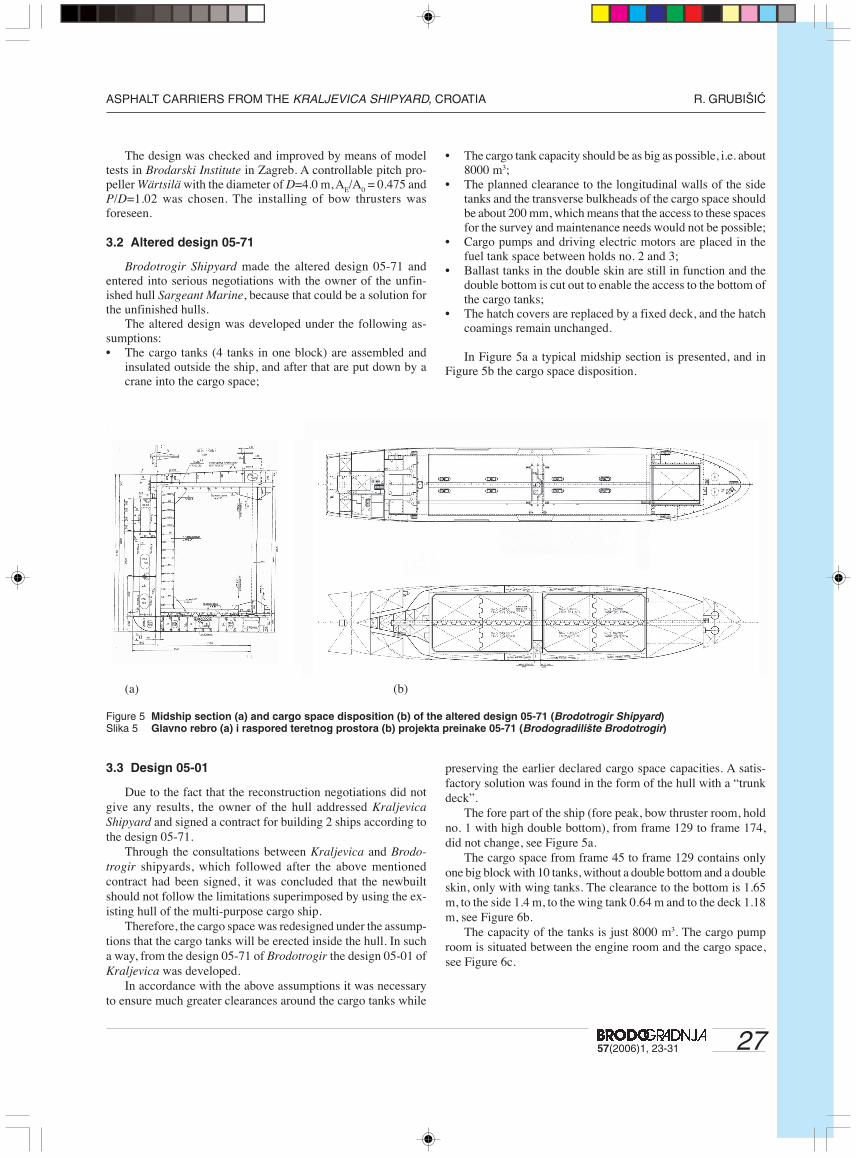
In Figure 5a a typical midship section is presented, and inFigure 5b the cargo space disposition.
(a) (b)
Figure 5 Midship section (a) and cargo space disposition (b) of the altered design 05-71 (Brodotrogir Shipyard)Slika 5 Glavno rebro (a) i raspored teretnog prostora (b) projekta preinake 05-71 (Brodogradiliπte Brodotrogir)
3.3 Design 05-01
Due to the fact that the reconstruction negotiations did notgive any results, the owner of the hull addressed Kraljevica
Shipyard and signed a contract for building 2 ships according tothe design 05-71.
Through the consultations between Kraljevica and Brodo-
trogir shipyards, which followed after the above mentionedcontract had been signed, it was concluded that the newbuiltshould not follow the limitations superimposed by using the ex-isting hull of the multi-purpose cargo ship.
Therefore, the cargo space was redesigned under the assump-tions that the cargo tanks will be erected inside the hull. In sucha way, from the design 05-71 of Brodotrogir the design 05-01 ofKraljevica was developed.
In accordance with the above assumptions it was necessaryto ensure much greater clearances around the cargo tanks while
preserving the earlier declared cargo space capacities. A satis-factory solution was found in the form of the hull with a “trunkdeck”.
The fore part of the ship (fore peak, bow thruster room, holdno. 1 with high double bottom), from frame 129 to frame 174,did not change, see Figure 5a.
The cargo space from frame 45 to frame 129 contains onlyone big block with 10 tanks, without a double bottom and a doubleskin, only with wing tanks. The clearance to the bottom is 1.65m, to the side 1.4 m, to the wing tank 0.64 m and to the deck 1.18m, see Figure 6b.
The capacity of the tanks is just 8000 m3. The cargo pumproom is situated between the engine room and the cargo space,see Figure 6c.

28 57(2006)1, 23-31
R. GRUBI©I∆ ASPHALT CARRIERS FROM THE KRALJEVICA SHIPYARD, CROATIA
a) Frame 129
• Complexity of the cargo loading/unloading system due to anunfavourable position of the pump room with respect to thetanks and the manifold.Although the concept of the design 05-01 was already certi-
fied from the strength, stability and damaged stability survivalaspects, the owner decided to give up some of the cargo tankscapacity for a “moderate”, i.e. less “avant-garde” solution. The
b) Frame 83
c) Longitudinal section and deck plan
Figure 6 Design 05-01 (Kraljevica Shipyard)Slika 6 Projekt 05-01 (Brodogradiliπte Kraljevica)
3.4 Final design
In the design 05-01 certain weaknesses were discovered, suchas:• Unfavourable interaction between the stiff and long cargo
tank and the flexible ship structure (without double bottom,double skin and transverse bulkheads);

2957(2006)1, 23-31
ASPHALT CARRIERS FROM THE KRALJEVICA SHIPYARD, CROATIA R. GRUBI©I∆
result was the divisionof one big block ofcargo tanks into twosmaller ones and thereturn of the pumproom space in themiddle the ship. Thehydraulic drive of thecargo pumps is applied.The electro-hydraulicpower units are put intoa new deck house di-rectly behind the ma-nifold, and the heatersof the thermal oil aretransferred from theengine room onto the1st poop deck. Theentire capacity of thecargo tanks is reducedby about 250 m3. Thenumber of cargo tankswas successfully redu-ced from 11 to 9 byusing the stability ana-lysis (particularly Reg.25A of MARPOL:Stability during the loa-ding/unloading). Thishas resulted in propor-tional savings in all car-go systems.
Thus, the final de-sign, described in sec-tion 2 of this article andpresented in Figure 2,was obtained.
The stability surveyis carried out accordingto the “Code on IntactStability for All Types ofShips Covered by IMOInstruments”, the pre-vious Res. A. 749(18).For this purpose, 23characteristic loadingconditions, includingtwo conditions of theship loaded to the“tropical loading line”(T = 8.514 m), have beenchosen.
The damaged shipstability and floata-bility calculation wascarried out in order toaccess the ship’s com-pliance with followingrequirements:a) IMO Regulations for the Prevention of Oil Pollution from Ships,
Annex 1 of MARPOL 73/78 (Regulation 25, Subdivision andStability) and Amendments 1992 to Annex (Regulation 13F);
Table 3 List of damage cases of the final design (Kraljevica Shipyard)Tablica 3 Lista sluËajeva oπteÊenja konaËnog projekta
(Brodogradiliπte Kraljevica)
b) International Code for the Construction and Equipment ofShip Carrying Dangerous Chemicals in Bulk (IBC Code),Volume 1, Chapter 2, Ship Survival Capability and Locationof Cargo Tank, January, 1989;
c) Regulation 27 of the 1966 Load Line Convention (LLC).

30 57(2006)1, 23-31
R. GRUBI©I∆ ASPHALT CARRIERS FROM THE KRALJEVICA SHIPYARD, CROATIA
For this purpose the characteristic load cases chosen fromthe Loading Manual were checked, where also the contents ofthe damaged tanks correspond to the relevant loading condition.For this design, 15 damage cases were chosen, which are pre-sented in Table 3.
In Figure 7 the plan of the damaged (flooded) spaces of thedamage case no. 6 from Table 3 is shown.
In Figure 8 the typical curve of stability levers for the givendamage case no. 6 from Table 3 is presented.
Figure 8 Typical curve of stability levers for damage case no. 6from Table 3
Slika 8 TipiËna krivulja poluga stabiliteta za sluËaj oπteÊenjabr.6 iz tablice 3.
4 Correlation instead of conclusion
Due to the fact that this is only the 1st part of the integralpresentation of the given asphalt carrier, and that the final con-clusions will be given at the end of the 2nd part, only some corre-lating features of the final design are presented here.
The measurements performed on the delivered ship Asphalt
Seminole confirmed the design (contracted) predictions concern-ing the deadweight and the speed, see Table 4.
Table 4 Comparison of the final design predictions with the full-scale measurements
Tablica 4 Usporedba prognoze konaËnog projekta s rezultatimamjerenja u naravi
Design Measurement
Deadweight at Tmax
= 8.34 m 9200 t 9230 t
Service speed (15%), 3128 kW, 13.7 kn 13.74 kn
Td = 6.75 m
Service speed (15%), 3128 kW, 13.4 kn 13.42 kn
Tmax
= 8.34 m
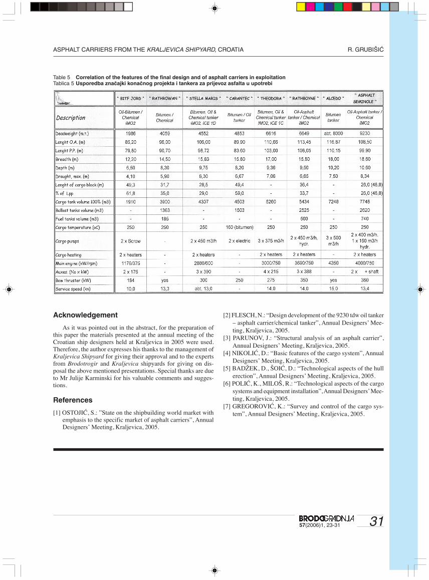
At the end of this part a correlation of the most significantfeatures of the final design and of several asphalt carriers al-ready in exploitation is made and presented in Table 5.
Figure 7 Plan of damaged (flooded) spaces for damage case no. 6 from Table 3Slika 7 Plan oπteÊenih (naplavljenih) prostora za sluËaj oπteÊenja br. 6 iz tablice 3.
3157(2006)1, 23-31
ASPHALT CARRIERS FROM THE KRALJEVICA SHIPYARD, CROATIA R. GRUBI©I∆
Acknowledgement
As it was pointed out in the abstract, for the preparation ofthis paper the materials presented at the annual meeting of theCroatian ship designers held at Kraljevica in 2005 were used.Therefore, the author expresses his thanks to the management ofKraljevica Shipyard for giving their approval and to the expertsfrom Brodotrogir and Kraljevica shipyards for giving on dis-posal the above mentioned presentations. Special thanks are dueto Mr Julije Karminski for his valuable comments and sugges-tions.
References
[1] OSTOJIĆ, S.: ”State on the shipbuilding world market withemphasis to the specific market of asphalt carriers”, AnnualDesigners’ Meeting, Kraljevica, 2005.
[2] FLESCH, N.: “Design development of the 9230 tdw oil tanker– asphalt carrier/chemical tanker”, Annual Designers’ Mee-ting, Kraljevica, 2005.
[3] PARUNOV, J.: “Structural analysis of an asphalt carrier”,Annual Designers’ Meeting, Kraljevica, 2005.
[4] NIKOLIĆ, D.: “Basic features of the cargo system”, AnnualDesigners’ Meeting, Kraljevica, 2005.
[5] BADŽEK, D., ŠOIĆ, D.: “Technological aspects of the hullerection”, Annual Designers’ Meeting, Kraljevica, 2005.
[6] POLIĆ, K., MILOŠ, R.: “Technological aspects of the cargosystems and equipment installation”, Annual Designers’ Mee-ting, Kraljevica, 2005.
[7] GREGOROVIĆ, K.: “Survey and control of the cargo sys-tem”, Annual Designers’ Meeting, Kraljevica, 2005.
Table 5 Correlation of the features of the final design and of asphalt carriers in exploitationTablica 5 Usporedba znaËajki konaËnog projekta i tankera za prijevoz asfalta u upotrebi