Embed Size (px)
Citation preview
RAM PIPE REQUAL Pipeline Requalification Guidelines Project Report 3
Risk Assessment and Management (RAM) Based Guidelines for Requalification of Marine Pipelines
- '1'0
Petroleos Mexicanos (PEMEX)
1 Instituto Mexicano de Petroleo (IMP)
Minerals Management Service (MMS)
BY Professor Robert Bea
Dr. Tao Xu
Marine Technology & Management Group University of California at Berkeley
Dr. Wally Orisamolu United Technologies Research Center & Professor Ahsan Kareem
Postdoctoral Research Associate Xinzhong Chen
Department of Civil Engineering and Geological Sciences UniversityofNotreDame
December 15,1999 MMS Order No. 1435-01-98-PO-15219 PEMEX Contrato No. 7TRDIN022798
RAM PIPE REQUAL Project
Report 3
Risk Assessment and Management (RAM) Based
Requalification Guidelines for Marine Pipelines
BY Professor Robert Bea
Dr. Tao Xu Marine Technology & Management Group
University of California at Berkeley
Dr. Wally Orisamolu United Technologies Research Center
And Professor Ahsan Kareem
Postdoctoral Research Associate Xinzhong Chen University of Notre Dame
MMS Order No. 1435-01-98-PO-15219
PEMEX Contrato No. 7TRDIN022798
Table of Contents
LIST OF SYMBOLS ................................................................................................................... 111 ............................................................................................................... 1.0 INTRODUCTION 1
2.0 RAM PIPE REQUAL ......................................................................................................... 6
3.0 PIPELINE REQUALIFICATION FORMULATIONS & CRITERIA ............................ 9 TABLE 3.1 . PIPELINE CAPACITIES ................................................................................................. -9 TABLE 3.2 . PIPELINE LOADINGS & PRESSURES BIASES AND UNCERTAINTIES ................................ 10 TABLE 3.3 . PIPELINE DESIGN AND REASSESSMENT ULTIMATE LIMIT STATE ANNUAL SAFETY
....................................................................................................................................... INDICES 11 TABLE 3.4 -IN-PLACE REASSESSMENT WORKING STRESS FACTORS ............................................... 12
........................................................... TABLE 3.5 - IN-PLACE REASSESSMENT LOADING FACTORS 12 ...................................................... TABLE 3.6 . IN-PLACE REASSESSME~T RESISTANCE FACTORS 13
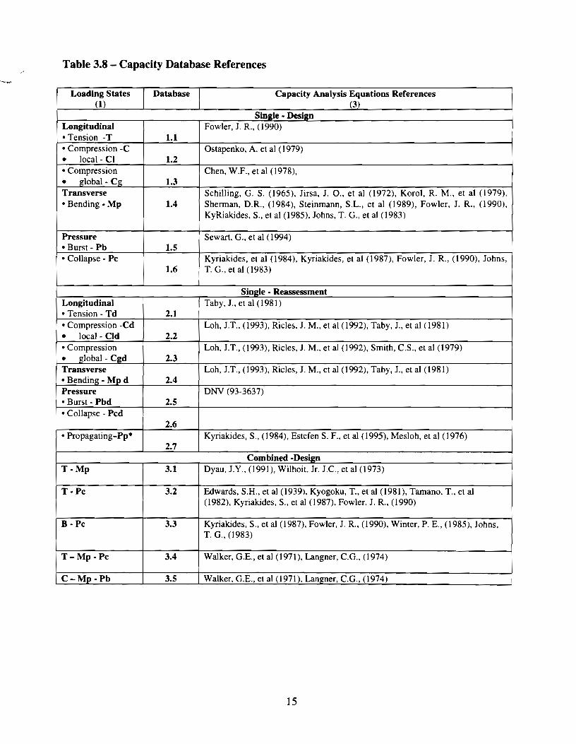
........................................................................... TABLE 3.7 -ANALYSIS EQUATIONS REFERENCES 14 .......................................................................... TABLE 3.8 - CAPACITY DATABASE REFERENCES 15
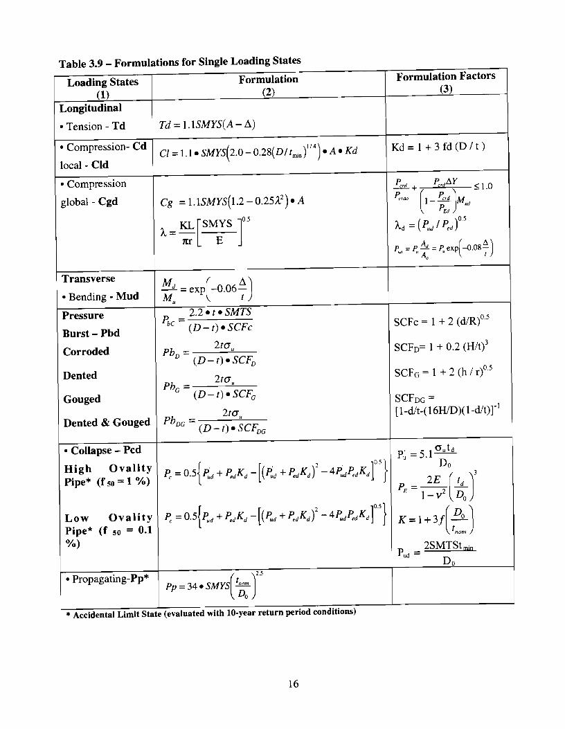
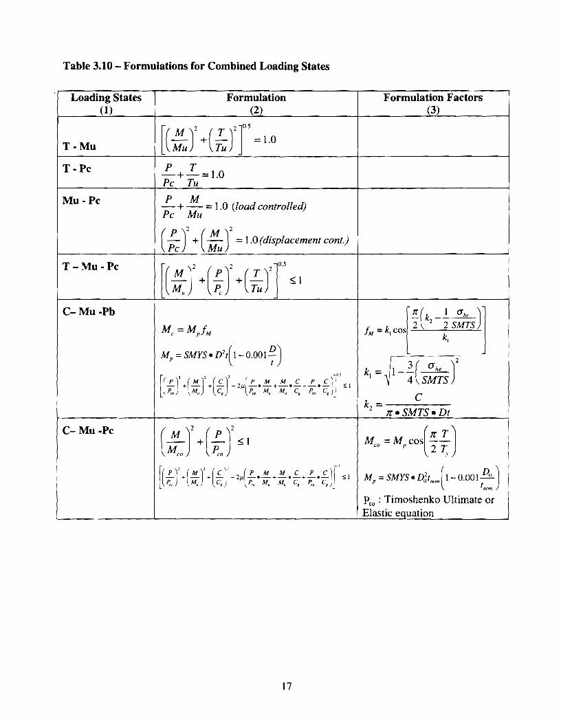
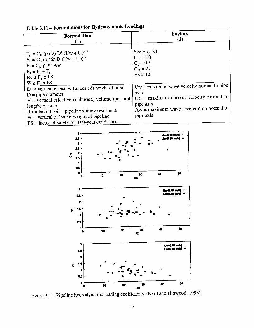
....................................................... TABLE 3.9 - FORMULATIONS FOR SINGLE LOADING STATES 1 6 TABLE 3.10 - FORMULATIONS FOR COMBINED LOADING STATES ................................................... 17 TABLE 3.1 1 . FORMULATIONS FOR HYDRODYNAMIC LOADINGS .................................................... 18
..................................................................................... 4.0 HYDRODYNAMIC LOADINGS 19
................................................................................................................. 4 . 1 INTRODUCTION 19 ............................................................................................ 4.2 WATER PARTICLE VELOCITY 20
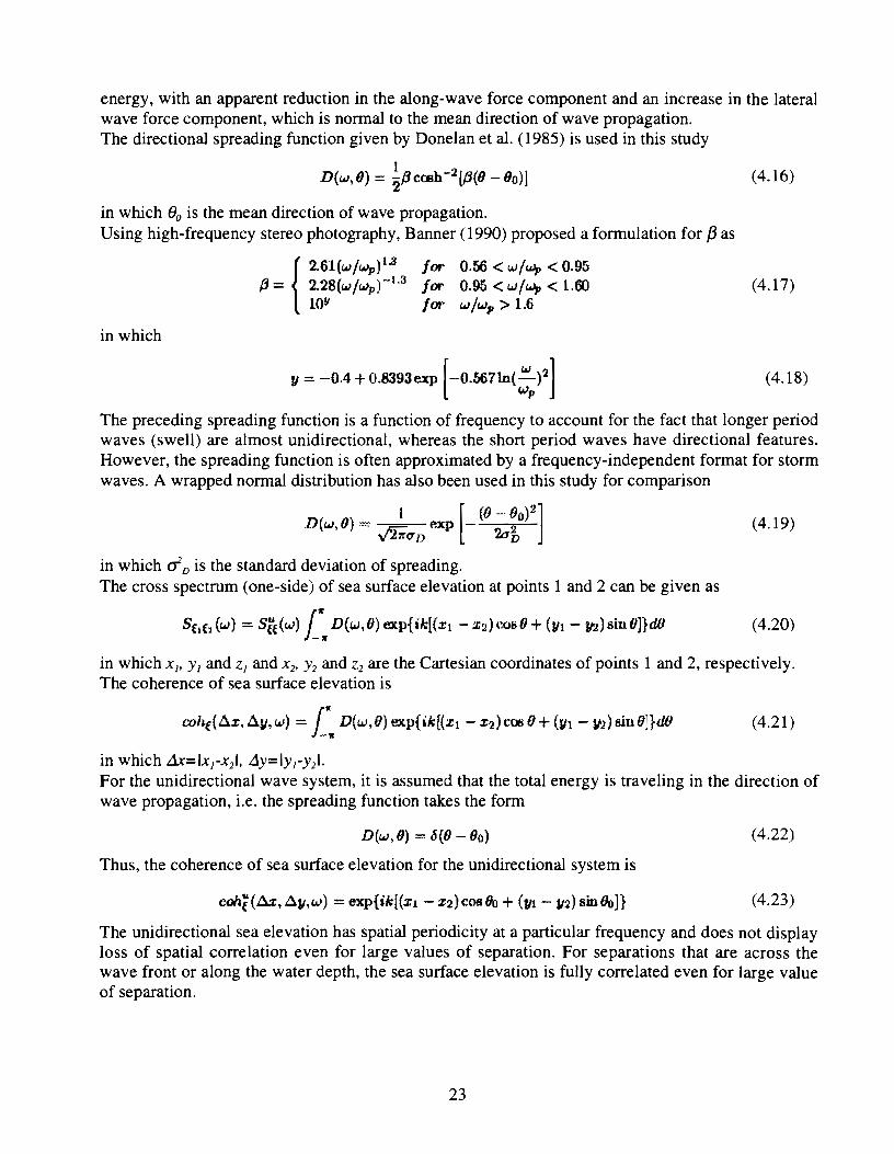
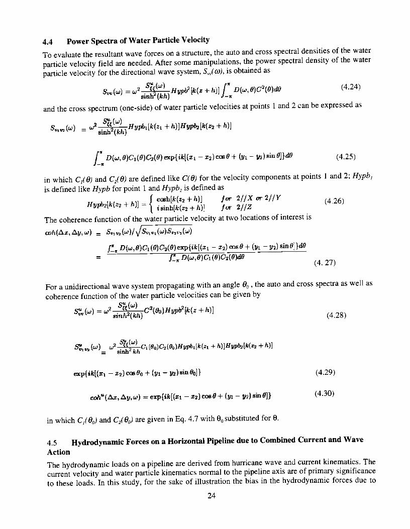
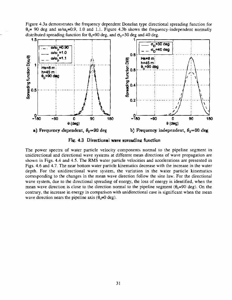
........................................................................ 4.3 DIRECTIONAL WAVE SURFACE SPECTRUM -22 .............................................................. 4.4 POWER SPECTRA OF WATER PARTICLE VELOCITY 24
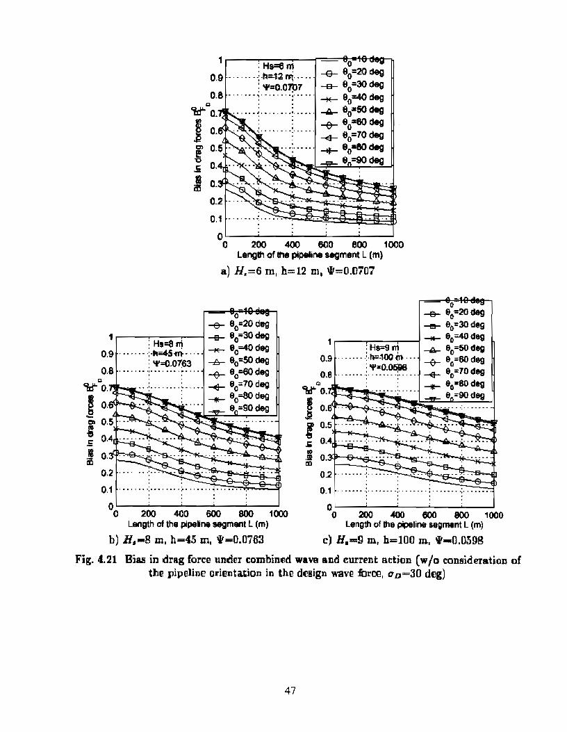
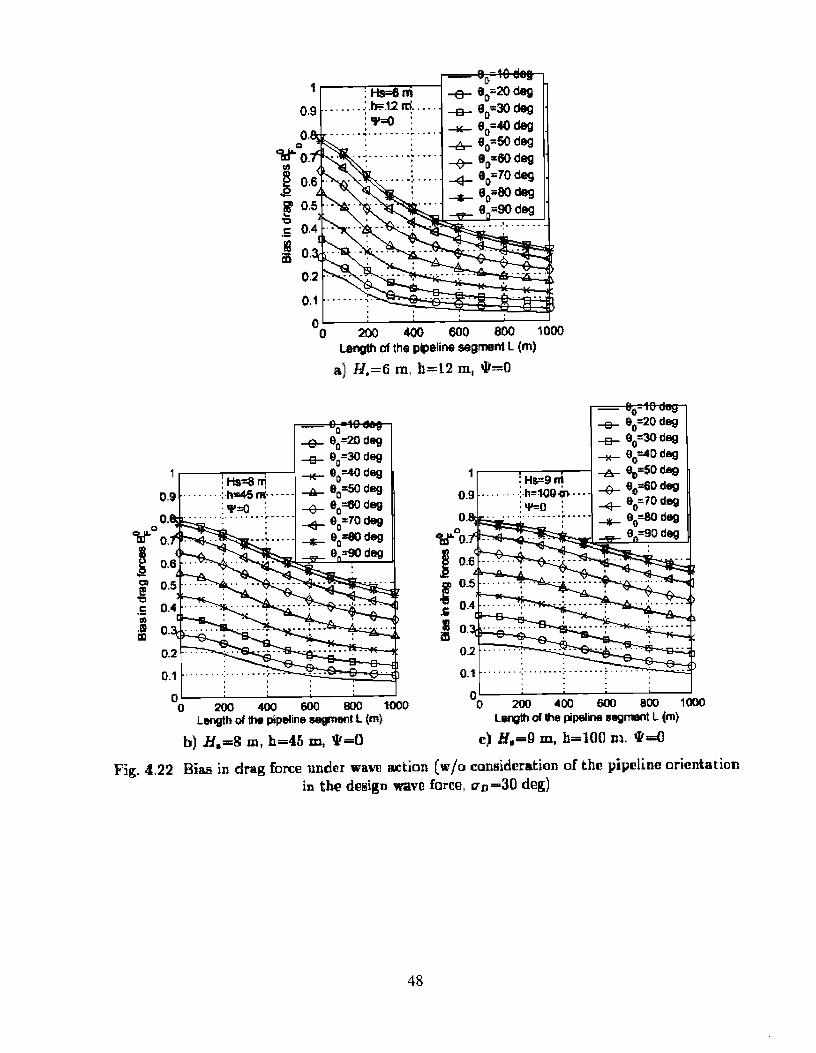
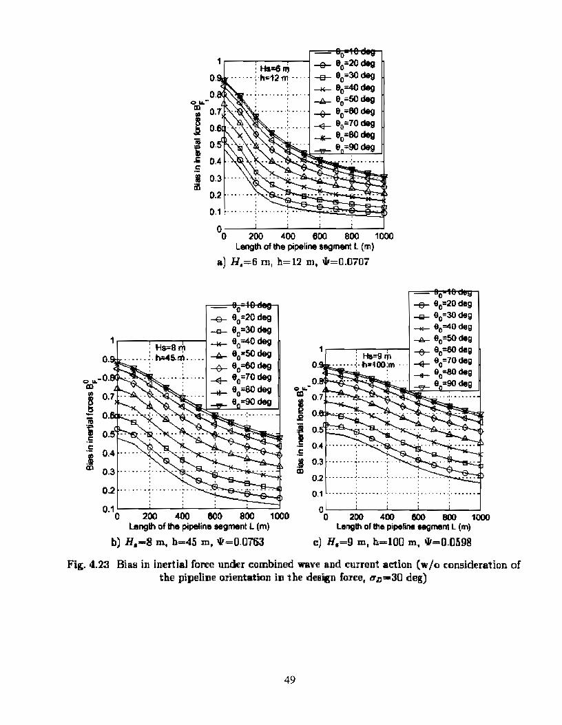
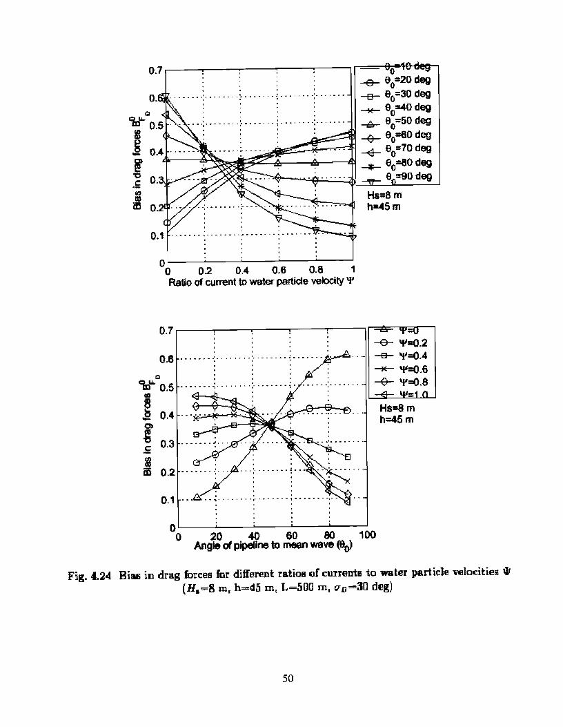
4.5 HYDRODYNAMIC FORCES ON A HORIZONTAL PIPELINE DUE TO COMBINED CURRENT AND
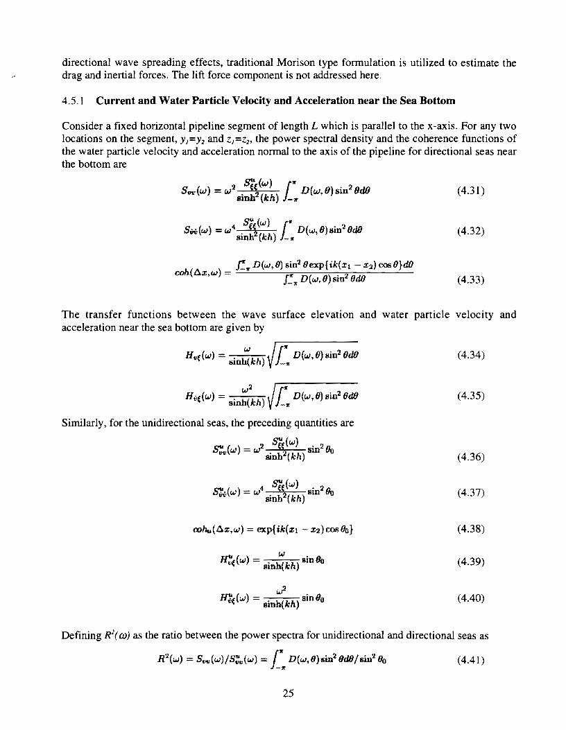
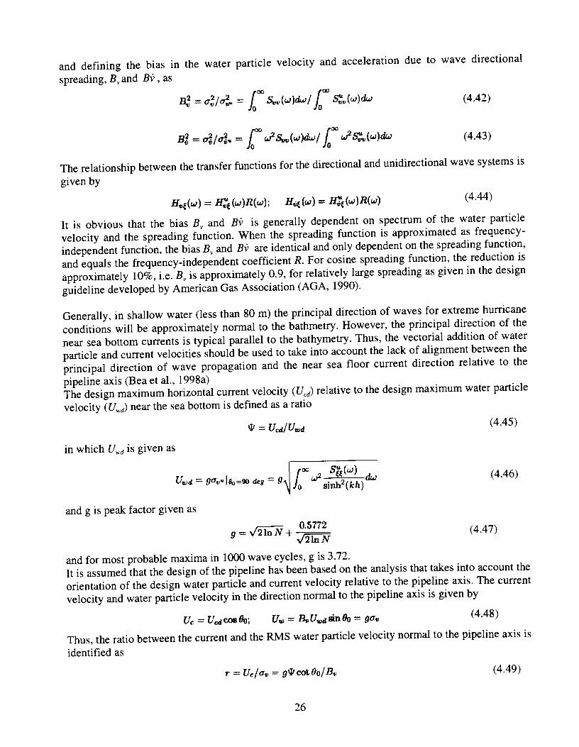
............................................................................................................................ WAVE ACTION -24 4.5.1 Current and Water Particle Velocity and Acceleration near the Sea Bottom ............ 25 4.5.2 Hydrodynamic Drag Force ...................................................................................... 27 4.5.3 Hydrodynamic Inertial Force .................................................................................. 29
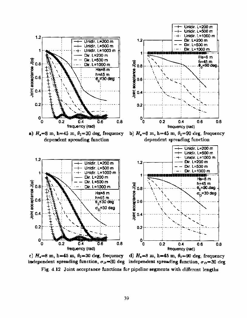
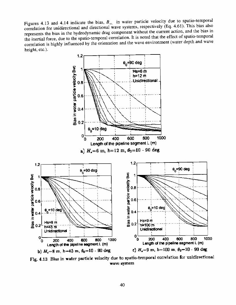
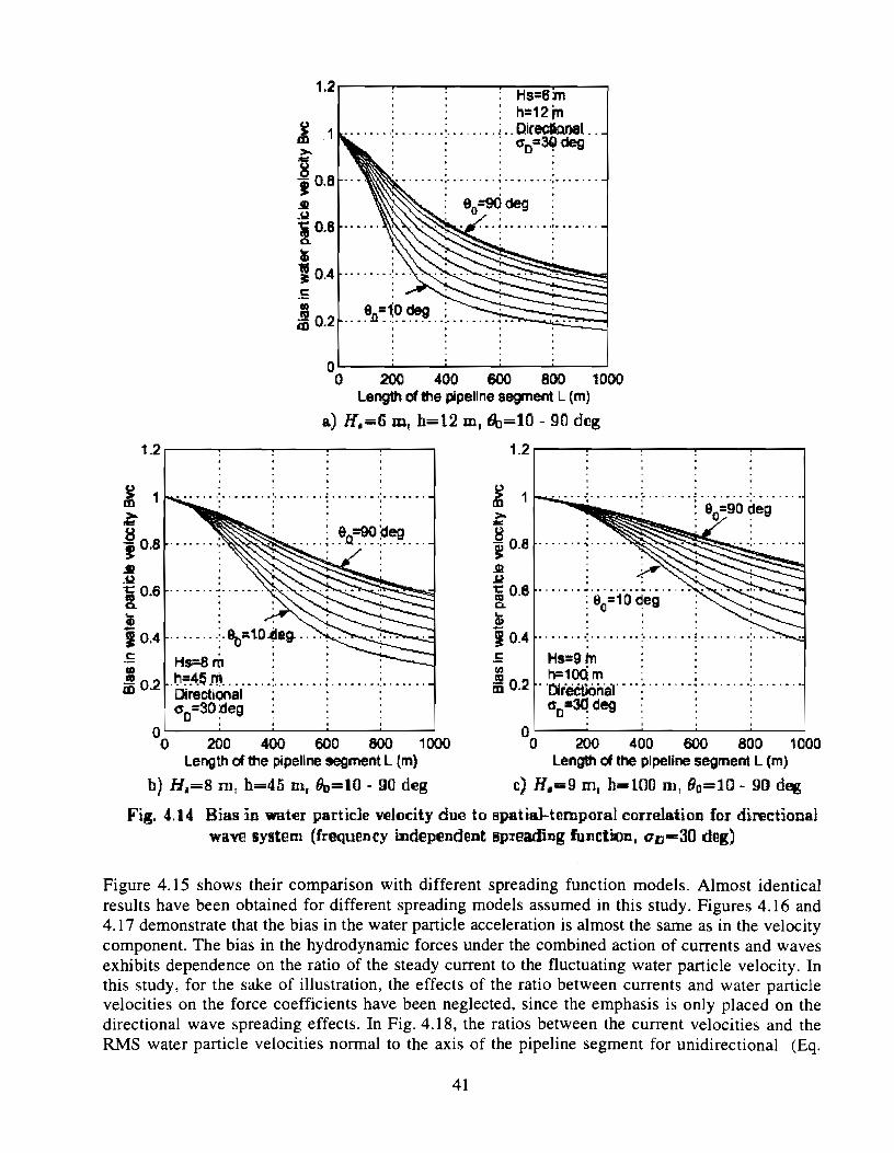
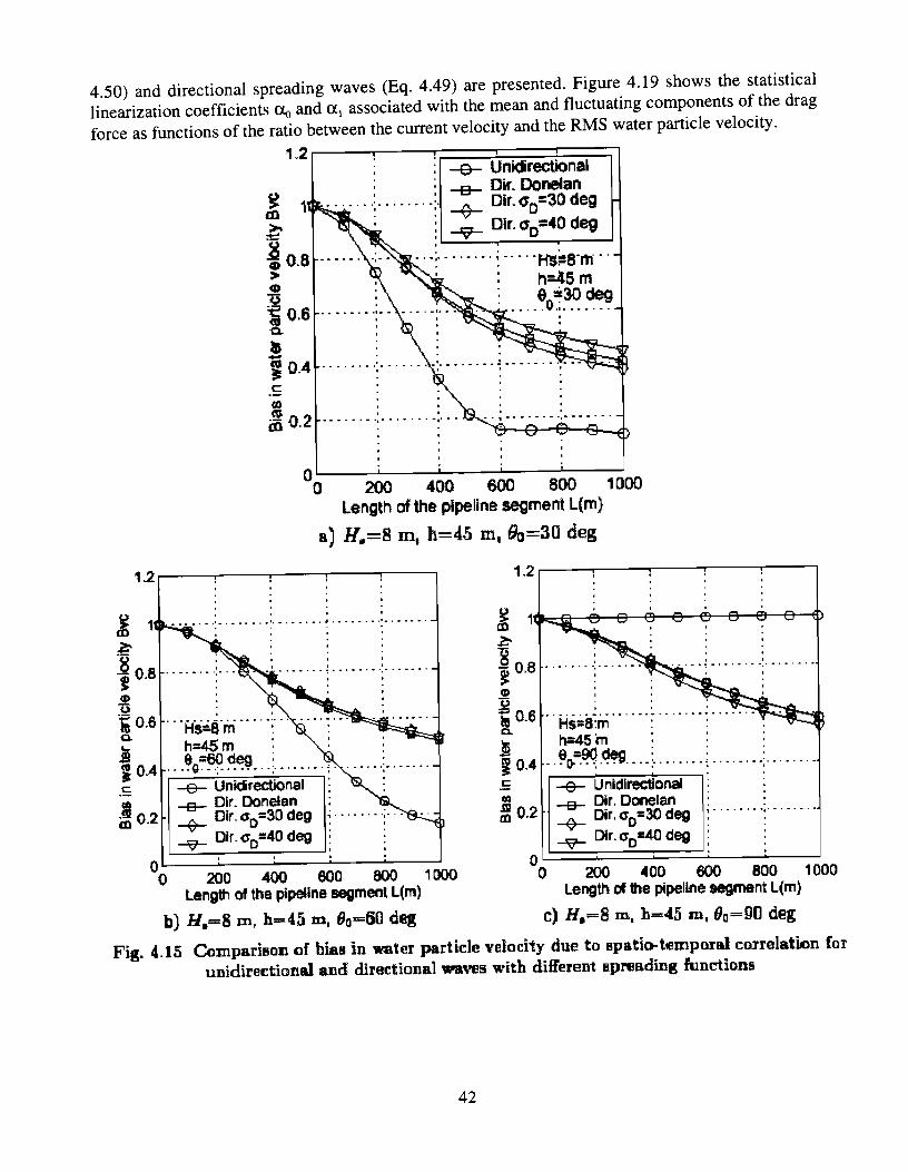
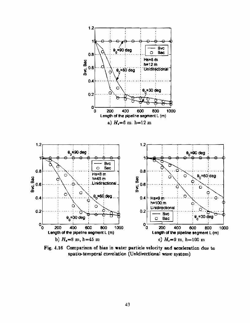
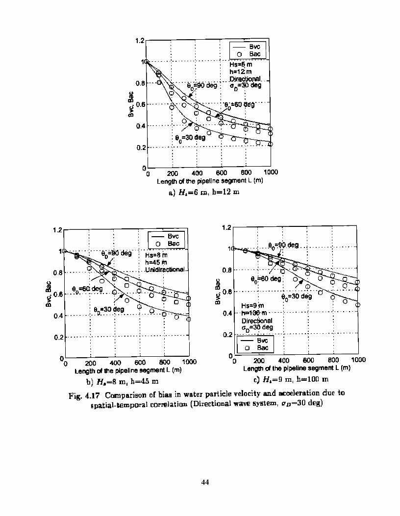
................................................................................ 4.6 NUMERICAL RESULTS AND ANALYSIS 30 .................................................................................................. 3.7 CONCLUDING REMARKS 51
................................................................................................................. 4.8 FUTURE WORK 52 .................................................................................................................... 4.9 REFERENCES 52
......................................................................................................................... 4.10 SYMBOLS 54
.................................................................... 5.0 PIPELINE SYSTEM CONSIDERATIONS 56
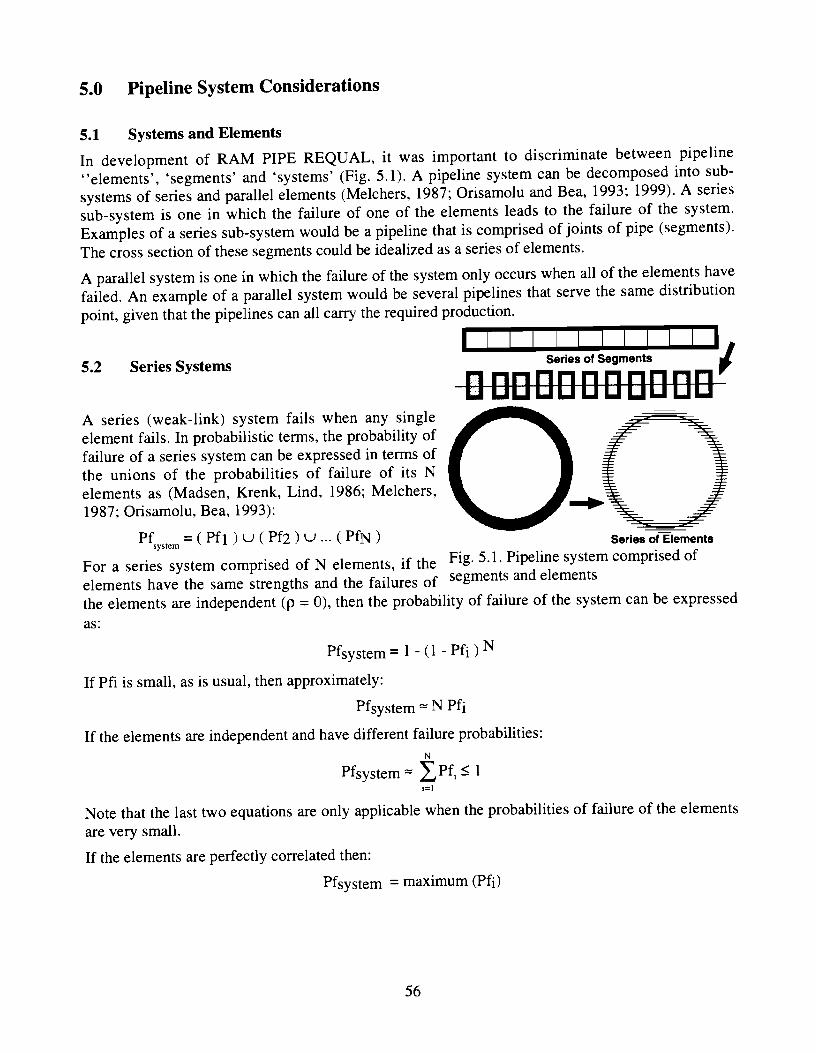
5.1 SYSTEMS AND ELEMENTS ................................................................................................. 56 5.2 S E ~ SYSTEMS ........................................................................................................... 56
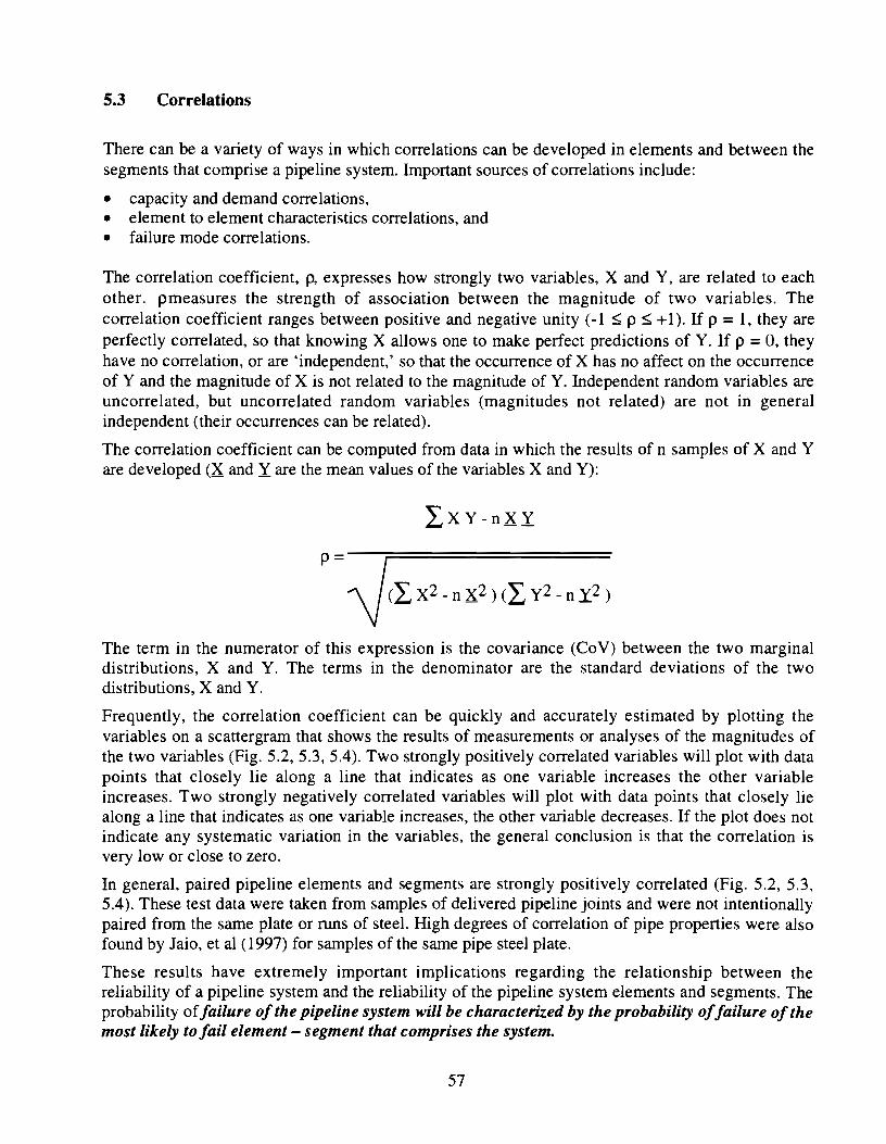
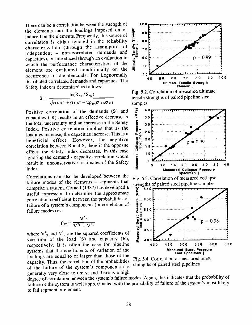
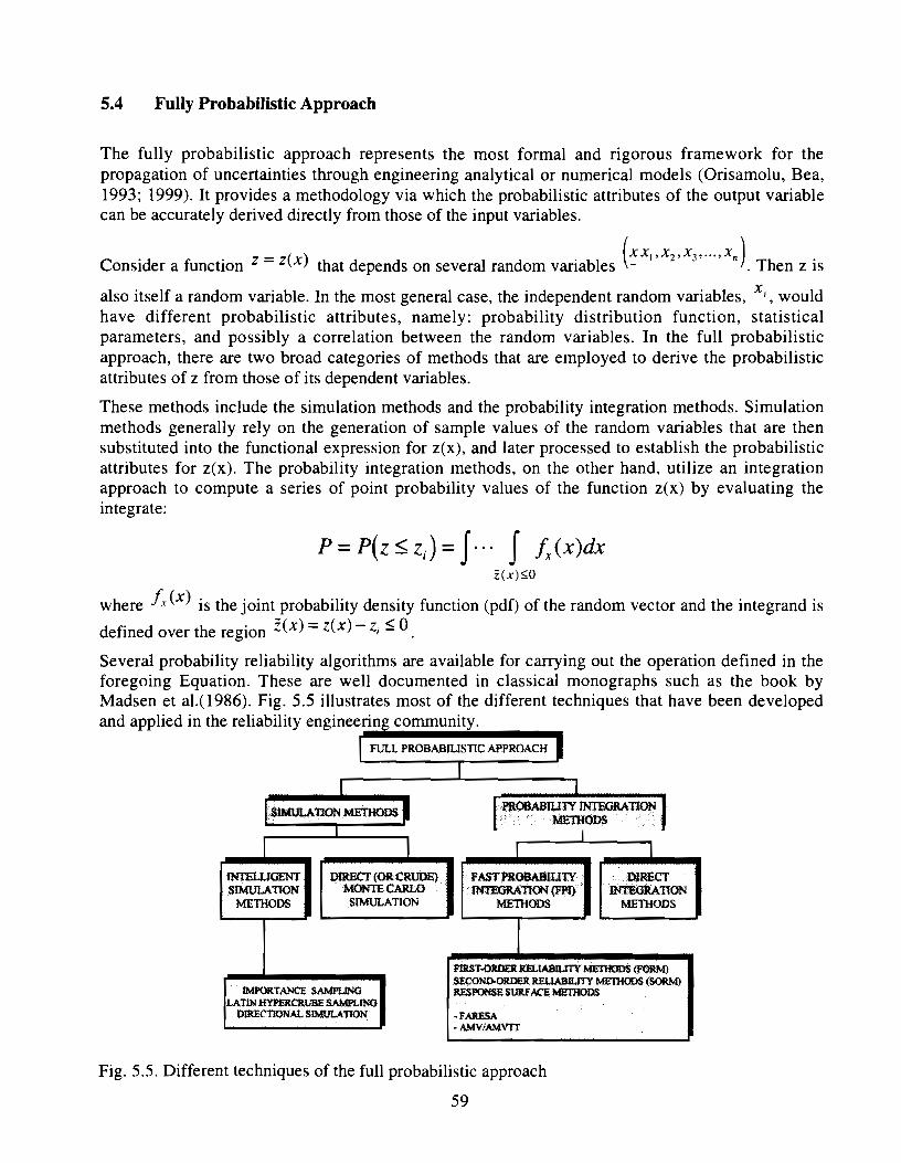
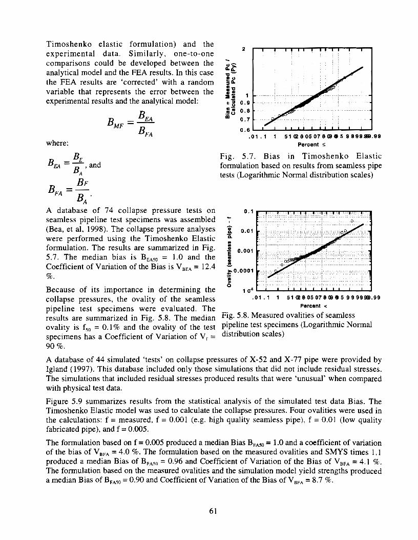
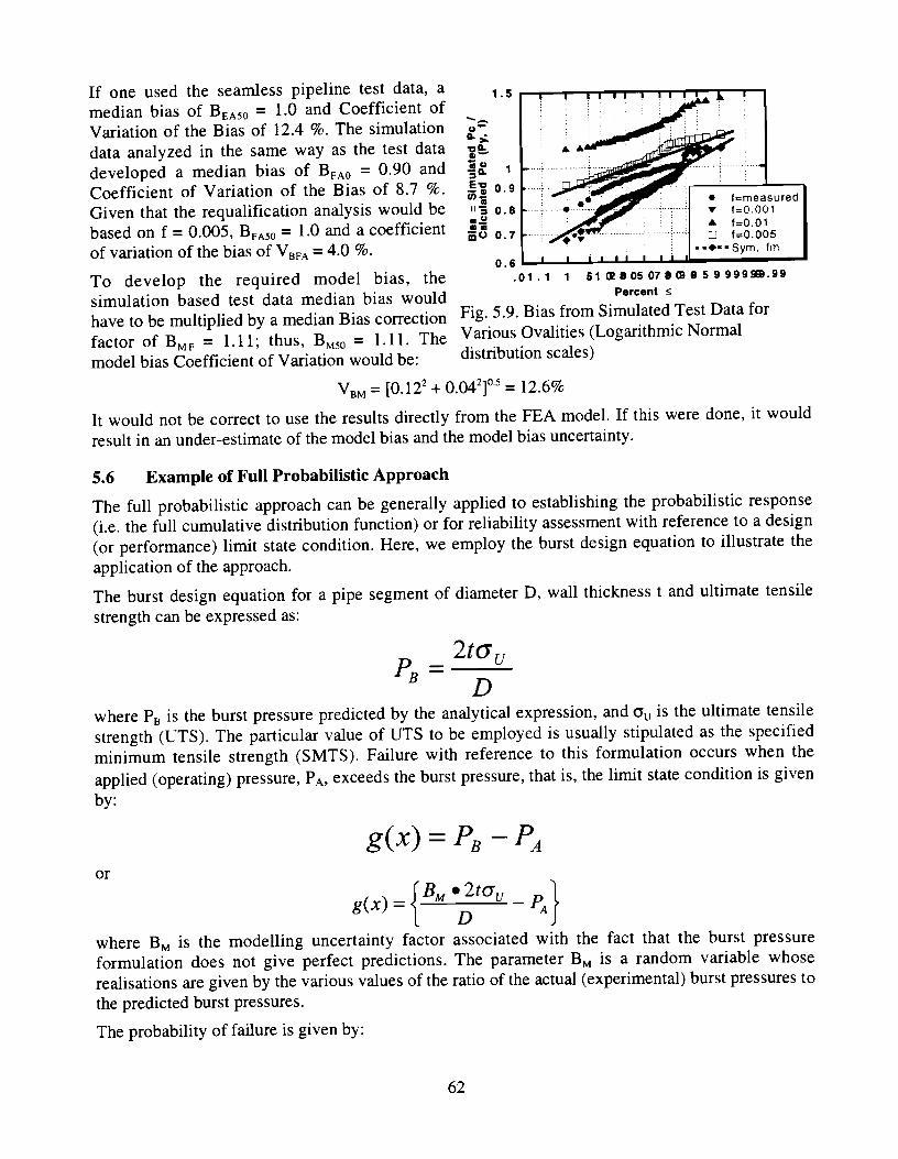
................................................................................................................ 5.3 CORRELATIONS 57 5.4 FULLY PROBABILISTIC APPROACH ................................................................................... 59 5.5 PROBABILISTIC RELATIONSH~P BETWEEN EXPERIMENTAL AND NUMERICAL DATABASES ..... 60
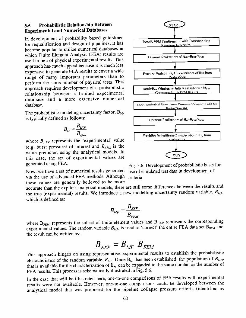
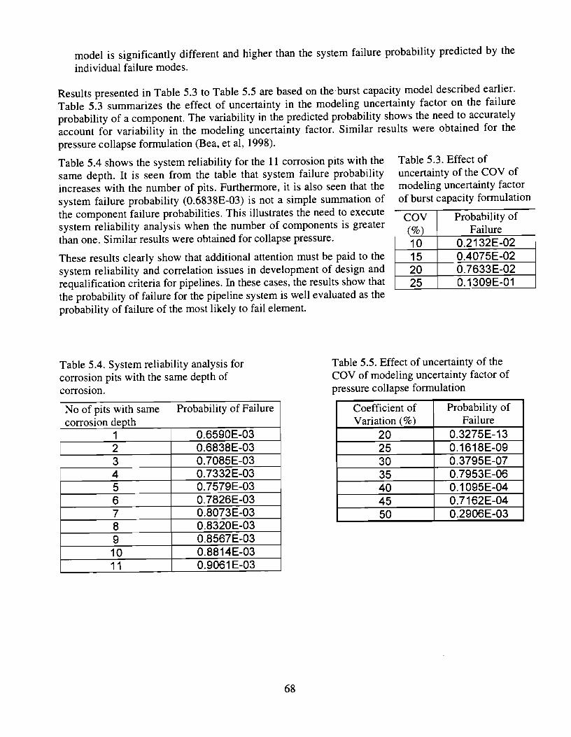
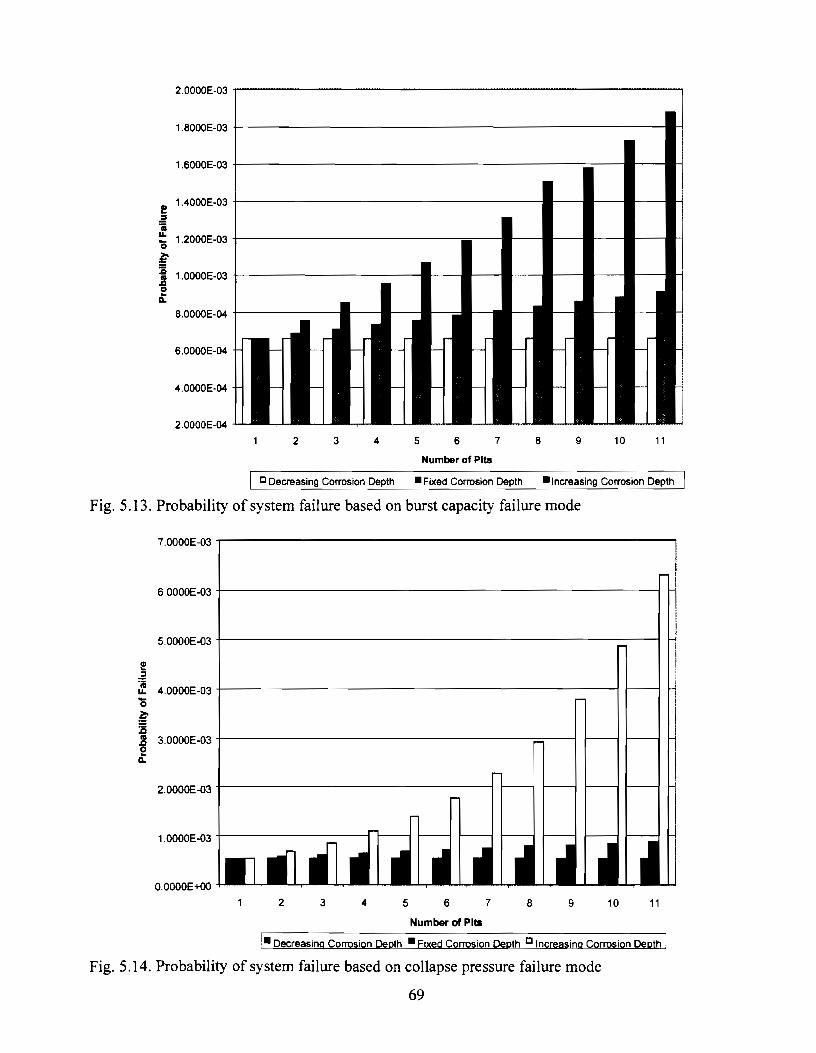
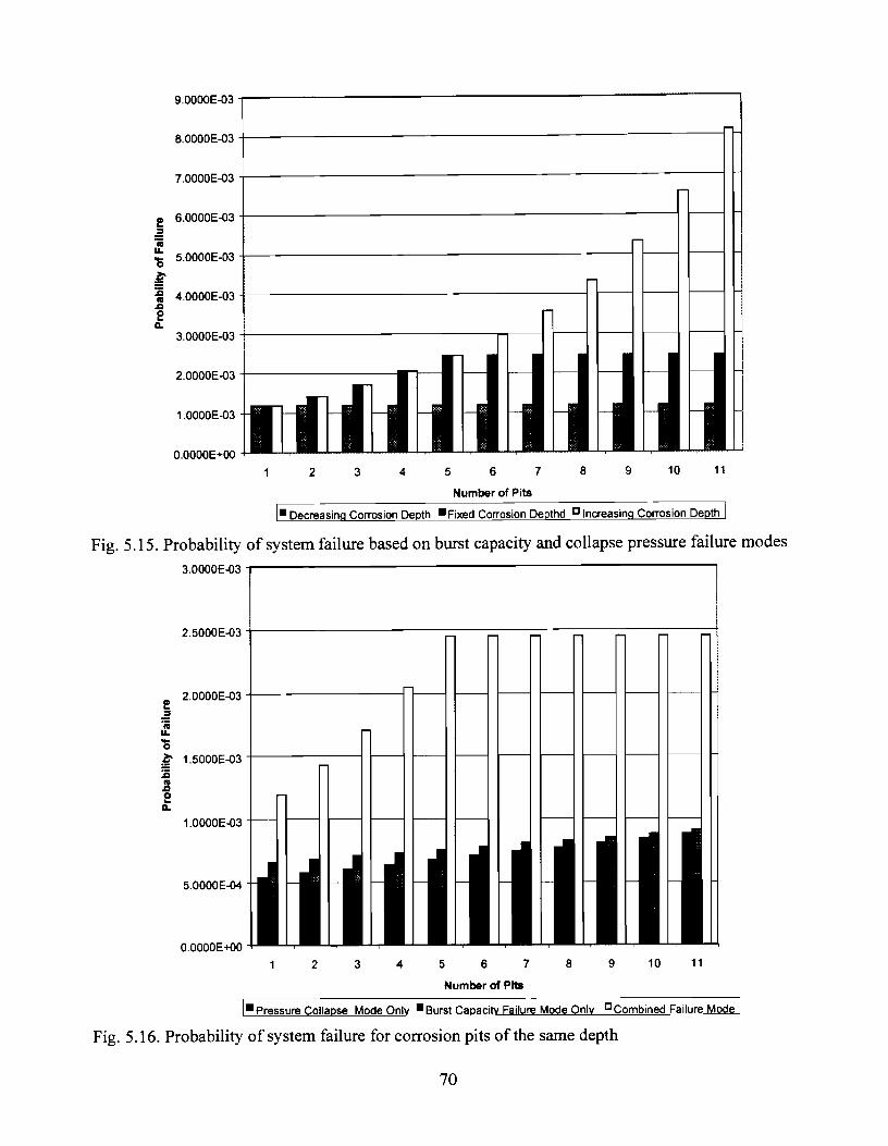
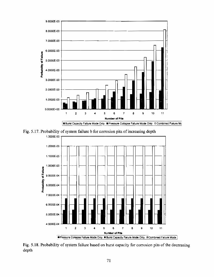
.............................................................. 5.6 EXAMPLE OF FULL PROBABILISTIC APPROACH 6 2 5.7 PIPELINE SYSTEM RELIABILITY MODELING USING A FULLY PROBABILISTIC APPROACH ...... 64
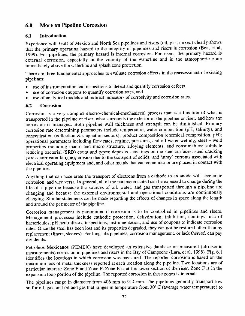
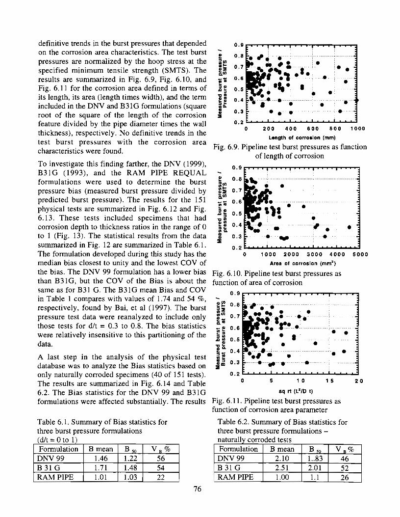
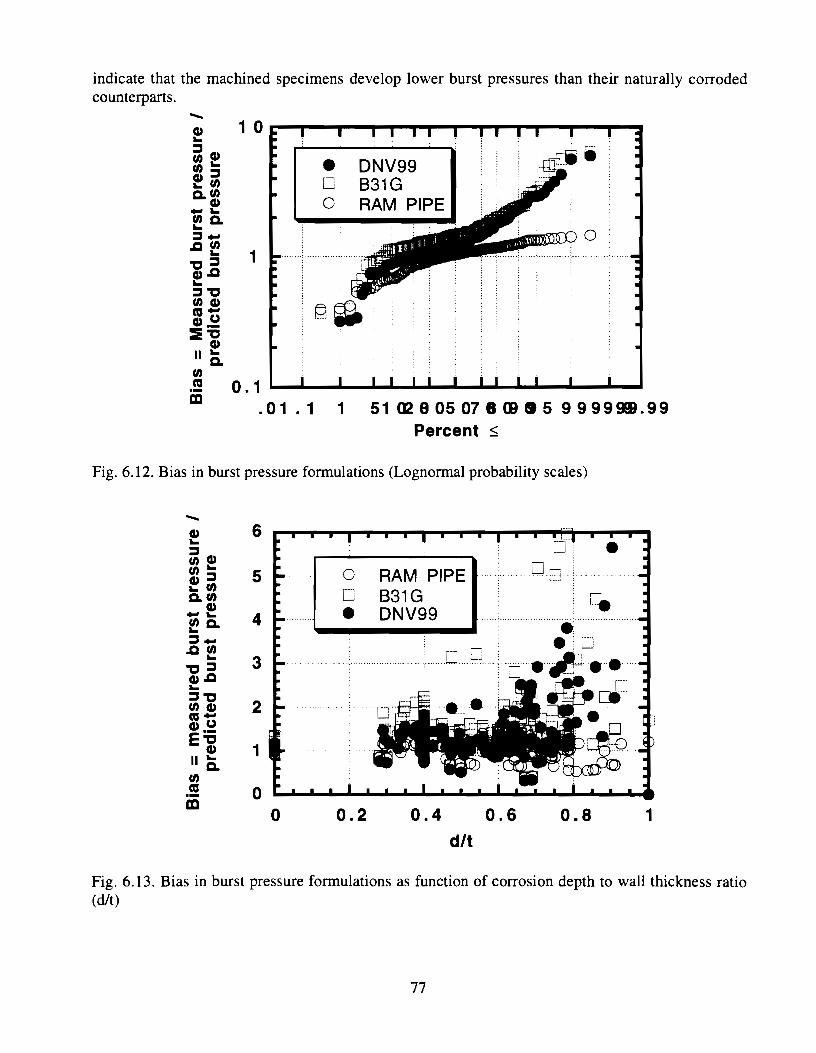
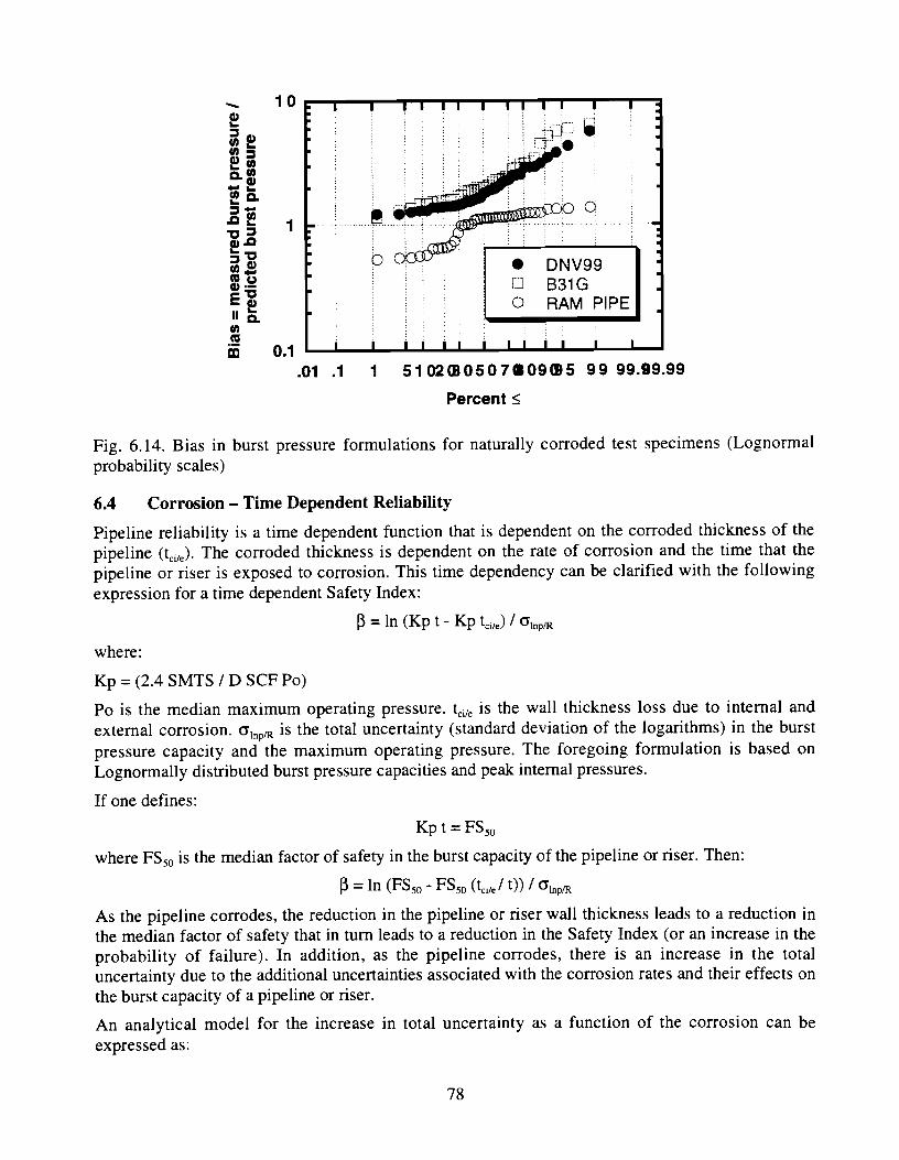
6.0 MORE ON PIPELINE CORROSION ............................................................................. 73
7.0 ACKNOWLEDGEMENTS .............................................................................................. 83
8.0 REFERENCES ................................................................................................................. 84
List of Symbols
Abbreviations
API ASME ASTM AGA A1 SC BSI DNV IMP IS0 PEMEX SUPERB
ALS ASD CTOD FEA LRFD MOP OTC OP
FS SMYS SMTS WSD LRFD ULS SLS SCF SNCF cov X52 X65 X52
- American Petroleum Institute - American Society of Mechanical Engineers - American Society of Testing Material - American Gas Association - American Institute of Steel Construction, Inc. - British Standard Institute - Det Norske Veritas - Institute Mexicano de Petroleo - International Standard Organization - Petroleos Mexicano - Submarine Pipeline Probabilistic Based Design Project
- Accidental Limit States - Allowable Stress Design - Critical Tip Opening Displacement - Finite Element Analysis - Load Resistance Factor Design - Maximum operating pressure - Offshore Technology Conference - Operating Pressure
- Factor of Safety - Specified Minimum Yield Strength of pipe, in psi ( N 1 mm') - Specified Minimum Ultimate Tensile Strength of pipe, in psi ( N / mm2) - Working stress design - Load Resistance Factor Design - Ultimate Limit State - Serviceability Limit States - Stress Concentration Factor - Strain Concentration Factor - Coefficient of Variation - Material grade, yield strength = 52 ksi=358 Mpa - Material grade, yield strength = 65 ksi=448 Mpa - Material grade, yield strength = 70 ksi=530 Mpa
Subscripts 0 d 9 r res CO
u P g 1 F50
- mean - design - circumferential - radial - residual - collapse - ultimate capacity - plastic capacity - global - local - Median
Superscripts M - Moment P - Pressure T - Tension C - Compression
Roman Symbols
General B~so - Median bias factor V - Coefficient of Variation
Y - Load Factor cP - Resistance Factor S - Demand R - Capacity
P - Reliability Index
Design A - Cross sectional area of pipe steel, in inches2 ( mm')
A, - Internal cross sectional area of the pipe, in inches2 ( mm')
A0 - External cross sectional area of the pipe
c I -Inelastic local buckling strength in stress units, pond per square inch ( N / mm2)
C , - Inelastic global buckling strength in stress units, pond per square inch ( N / mm2) D - Outside diameter of pipe (Equation dependent) D i - Inside diameter of pipe, in inches (mm) = (D - 2t)
D"mx - Maximum diameter at any given cross section, in inches (mm)
Dmin - Minimum diameter at any given cross section, in inches (mm) E - Elastic modulus, in pounds per square inch ( N / mm2)
g( 6) - Collapse reduction factor K - Effective length factor L - Pipe length, in inches (mm) M - Applied moment, pond-inch (N-)
M P - Plastic moment capacity, pond-inch ( N,,)
P - Applied pressure pb - Minimum burst pressure of pipe, in psi ( N / rnrn2)
PC - Collapse pressure of the pipe, in psi ( N / mm2 )
Pe - Elastic collapse pressure of the pipe, in psi ( N / mm2)
Pi - Internal pressure in' the pipe, in psi ( N / mm2)
Po - External hydrostatic pressure, in psi ( N / mm2 )
P~ - Buckle propagation pressure, in psi ( N / mm2)
PY - Yield pressure at collapse, in psi ( N / mm2) r - Radius of gyration t nom - Nominal wall thickness of pipe, in inches (mm)
f min - Minimum measured wall thickness, in inches (mm) t - Pipe wall thickness, in inches (rnrn) fa - The initial ovalization n - The strain hardening parameter S - The anisotropy parameter T.3 - Axial tension in the pipe, in pounds (N)
Teff - Effective tension in pipe, in pounds (N)
Ty - Yield tension of the pipe, in pounds (N)
Tu - Tension Load Capacity 6 - Ovality 6, - the critical CTOD value Eo - the yield strain ama - the equivalent through-thickness crack size.
& b - Bending strain in the pipe
ECr - Critical strain E bm - The maximum bending strain
0 a - The axial stress
o h - Hoop stress 0 he - Effective hoop stress
0 re - Residual stress 0 e - Circumferential stress 'Jxu - The classic local elastic critical stress
0 l, - ultimate tensile stress
0, - yield stress
00 - flow stress h - Slenderness parameter
Reassessment
Ad - effective cross sectional area of damaged (dent) section
Ao - cross-sectional area of undamaged section d - damage depth AY - Primary out-of-straightness of a dented member
AYo - 0.001L
- Effective moment of inertia of undamaged cross-section - Effective length factor of undamaged member - Effective buckling length factor - Slenderness parameter of a dented member =(Pud / Ped)O.' - Ultimate moment capacity - Critical moment capacity (local buckling) - Ultimate negative moment capacity of dent section - Negative moment of dent section - Positive moment of dent section - Neutral moment of dent section - Critical axial buckling capacity of a dented member ( A / L > 0.00 1 ) - Critical axial buckling capacity of a dented member ( A / L = 0.001 ) - Euler load of undamaged member - Axial local buckling capacity - Axial column buckling capacity - Axial compression capacity - Axial compression capacity of a short dented member

1.0 Introduction
1.1 Objective
The objective of this joint United States - Mexico cooperative project is to develop and verify Risk Assessment and Management (RAM) based criteria and guidelines for reassessment and requalification of marine pipelines and risers. The project is identified as the RAM PIPE REQUAL project. This project was sponsored by the U. S. Minerals Management Service (MMS), Petroleos Mexicanos (PEMEX), and Instituto Mexicano del Petroleo (IMP).
1.2 Scope
The RAM PIPE REQUAL project addressed the following key aspects of criteria for requalification of conventional existing marine pipelines and risers:
Development of Safety and Serviceability Classifications (SSC) for different types of marine pipelines and risers that reflect the different types of products transported, the volumes transported and their importance to maintenance of productivity, and their potential consequences given loss of containment,
Definition of target reliabilities for different SSC of marine risers and pipelines,
Guidelines for assessment of pressure containment given corrosion and local damage including guidelines for evaluation of corrosion of non-piggable pipelines,
Guidelines for assessment of local, propagating, and global buckling of pipelines given corrosion and local damage,
Guidelines for assessment of hydrodynamic stability in extreme condition hurricanes, and
Guidelines for assessment of combined stresses during operations that reflect the effects of pressure testing and limitations in operating pressures.
Important additional parts of this project provided by PEMEX and IMP were:
Conduct of workshops and meetings in Mexico and the United States to review progress and developments from this project and to exchange technologies regarding the design and requalification of marine pipelines,
Provision of a scholarships to fund the work of graduate student researchers (GSR) that assisted in performing this project, and
a Provision of technical support, background, and field operations data to advance the objectives of the RAM PIPE REQUAL project.
1.3 Background
During the period 1996 - 1998, PEMEX (Petroleos Mexicanos) and IMP (Instituto Mexicanos del Petroleo) sponsored a project performed by the Marine Technology and Development Group of the University of California at Berkeley to help develop first-generation Reliability Assessment and Management (RAM) based guidelines for design of pipelines and risers in the Bay of Campeche. These guidelines were based on both Working Stress Design (WSD) and Load and Resistance Factor Design (LRFD) formats. The following guidelines were developed during this project:
a Serviceability and Safety Classifications (SSC) of pipelines and risers,
Guidelines for analysis of in-place pipeline loadings (demands) and capacities (resistances), and
Guidelines for analysis of on-bottom stability (hydrodynamic and geotechnical forces),
This work formed an important starting point for this project.
During the first phase of this project, PEMEX and IMP sponsored two international workshops that addressed the issues and challenges associated with development of criteria and guidelines for design and requalification of marine pipelines.
1.4 Approach
Very significant advances have been achieved in the requalification and reassessment of onshore pipelines. A very general strategy for the requalification of marine pipelines has been proposed by DNV and incorporated into the IS0 guidelines for reliability-based limit state design of pipelines (Collberg, Cramer, Bjornoyl, 1996; ISO, 1997). This project is founded on these significant advances.
The fundamental approach used in this project is a Risk Assessment and Management (RAM) approach. This approach is founded on two fundamental strategies:
1) Assess the risks (likelihoods, consequences) associated with existing pipelines, and
Manage the risks so as to produce acceptable and desirable quality in the pipeline operations.
It is recognized that some risks are knowable (can be foreseen) and can be managed to produce acceptable performance. Also, it is recognized that some risks are not knowable (can not be foreseen, and that management processes must be put in place to help manage such risks.
Applied to development of criteria for the requalification of pipelines, a RAM approach proceeds through the following steps:
Based on an assessment of costs and benefits associated with a particular development and generic type of system, and regulatory - legal requirements, national requirements, define the target reliabilities for the system. These target reliabilities should address the four quality attributes of the system including serviceability, safety, durability, and compatibility.
Characterize the environmental conditions (e.g. hurricane, nominal oceanographic, geologic) and the operating conditions (installation, production, maintenance) that can affect the pipeline during its life.
Based on the unique characteristics of the pipeline system characterize the 'demands' (imposed loads, induced forces, displacements) associated with the environmental and operating conditions. These demands and the associated conditions should address each of the four quality attributes of interest (serviceability, safety, durability, compatibility).
Evaluate the variabilities, uncertainties, and 'Biases' (differences between nominal and true values) associated with the demands. This evaluation must be consistent with the variabilities and uncertainties that were included in the decision process that determined the desirable and acceptable 'target' reliabilities for the system (Step #I).
For the pipeline system define how the elements will be designed according to a proposed engineering process (procedures, analyses, strategies used to determine the structure element sizes), how these elements will be configured into a system, how the system will be constructed, operated, maintained, and decommissioned (including Quality Assurance - QA, and Quality Control - QC processes).
Evaluate the variabilities, uncertainties, and 'Biases' (ratio of true or actual values to the predicted or nominal values) associated with the capacities of the pipeline elements and the
pipeline system for the anticipated environmental and operating conditions, construction, operations, and maintenance activities, and specified QA - QC programs). This evaluation must be consistent with the variabilities and uncertainties that were included in the decision process that determined the desirable and acceptable 'target' reliabilities for the system (Step #I).
Based on the results from Steps #1, #4, and #6, and for a specified 'design format' (e.g. Working Stress Design - WSD, Load and Resistance Factor Design- LRFD, Limit States Design - LSD), determine the design format factors (e.g. factors-of-safety for WSD, load and resistance factors for LRFD, and design conditions return periods for LSD).
It is important to note that several of these steps are highly interactive. For some systems, the loadings induced in the system are strongly dependent on the details of the design of the system. Thus, there is a potential coupling or interaction between Steps #3, #4, and #5. The assessment of variabilities and uncertainties in Steps #3 and #5 must be closely coordinated with the variabilities and uncertainties that are included in Step # l . The QA - QC processes that are to be used throughout the life-cycle of the system influence the characterizations of variabilities, uncertainties, and Biases in the 'capacities' of the system elements and the system itself. This is particularly true for the proposed IMR (Inspection, Maintenance, Repair) programs that are to be implemented during the system's life cycle. Design criteria, QA - QC, and IMR programs are highly interactive and are very inter-related.
The RAM PIPE REQUAL guidelines are based on the following current criteria and guidelines:
American Petroleum Institute (API RP 11 11, 1996, 1998),
Det Norske Veritas (DNV, 198 1, 1996, 1998, 1999),
American Gas Association (AGA, 1990, 1993),
American Society of Mechanical Engineers (ASME B3 I),
British Standards Institute (BSI 8010, PD 6493), and
International Standards Institute (ISO, 1998).
1.5 Guideline Development Premises
The design criteria and guideline formulations developed during this project are conditional on the following key premises:
The design and reassessment - requalification analytical models used in this project were based in so far as possible on analytical procedures that are founded on fundamental physics, materials, and mechanics theories.
The design and reassessment - requalification analytical models used in this -project were founded on in so far as possible on analytical procedures that result in un-biased (the analytical result equals the median - expected true value) assessments of the pipeline demands and capacities.
Physical test data and verified - calibrated analytical model data were used in so far as possible to characterize the uncertainties and variabilities associated with the pipeline demands and capacities.
The uncertainties and variabilities associated with the pipeline demands and capacities will be concordant with the uncertainties and variabilities associated with the background used to define the pipeline reliability goals.
1.6 Pipeline Operating Premises
The pipelines will be operated at a minimum pressure equal to the normal hydrostatic pressure exerted on the pipeline.
The pipelines will be maintained to minimize corrosion damage through coatings, cathodic protection, use of inhibitors, and dehydration so as to produce moderate corrosion during the life of the pipeline. If more than moderate corrosion is developed, then the reassessment capacity factors are modified to reflect the greater uncertainties and variabilities associated with severe corrosion.
The pipelines will be operated at a maximum pressure not to exceed the maximum design pressure. If pipelines are reassessed and requalified to a lower pressure than the maximum design pressure, they will be operated at the specified lower maximum operating pressure. Maximum incidental pressures will not exceed 10 % of the specified maximum operating pressures.
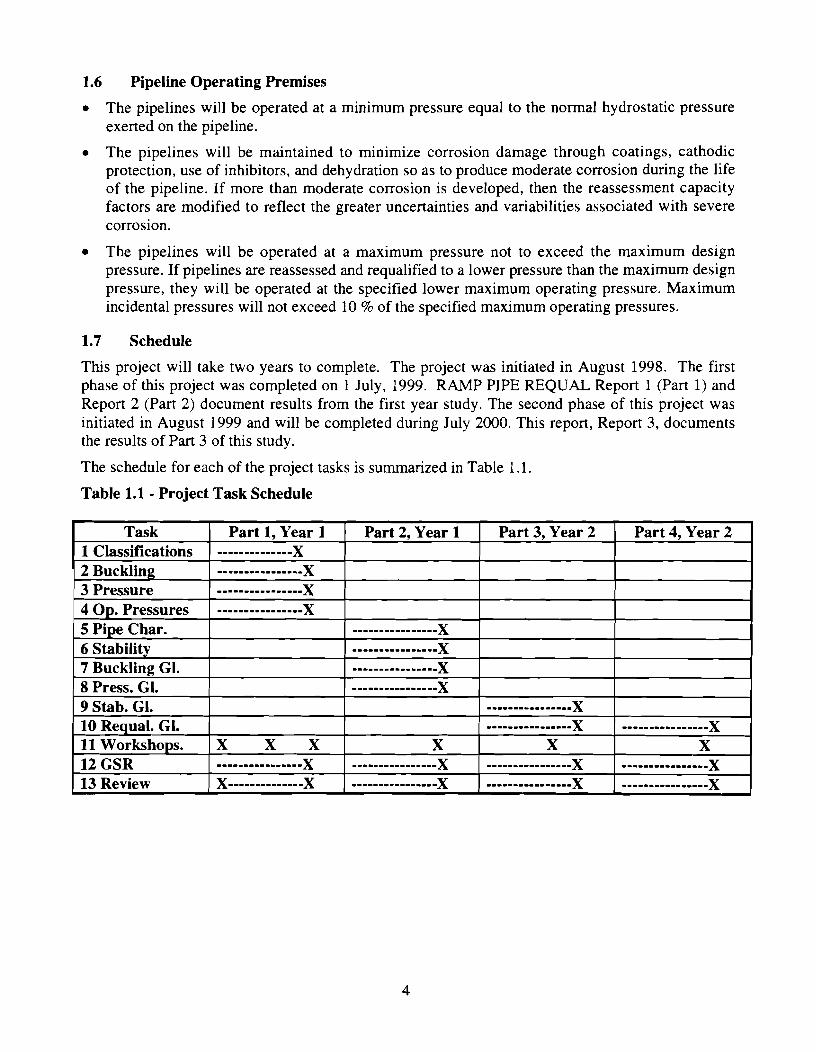
1.7 Schedule
This project will take two years to complete. The project was initiated in August 1998. The first phase of this project was completed on 1 July, 1999. RAMP PIPE REQUAL Report 1 (Part 1) and Report 2 (Part 2) document results from the first year study. The second phase of this project was initiated in August 1999 and will be completed during July 2000. This report, Report 3, documents the results of Part 3 of this study.
The schedule for each of the project tasks is summarized in Table 1.1.
Table 1.1 - Project Task Schedule
1.8 Project Reports
A report will document the developments from each of the four parts or phases of this project. The reports that will be issued at the end of each of the project phases are as follows:
Report 1 - Requalification Process and Objectives, Risk Assessment & Management Background, Pipeline and Riser Classifications and Targets, Templates for Requalification Guidelines, Pipeline Operating Pressures and Capacities (corrosion, denting, gouging - cracking).
Report 2 - Pipeline characteristics, Hydrodynamic Stability, Geotechnical Stability, Guidelines for Assessing Capacities of Defective and Damaged Pipelines.
Report 3 - Guidelines for Assessing Pipeline Stability (Hydrodynamic), System Reliability Considerations, More on Corrosion Effects, Preliminary Requalification Guidelines.
Report 4 - Guidelines for Requalifying and Reassessing Marine Pipelines.
2.0 RAM PIPE REQUAL
2.1 Attributes
Practicality is one of the most important attributes of an engineering approach. Industry experience indicates that a practical RAM PIPE REQUAL approach should embody the following attributes:
Simplicity - ease of use and implementation,
Versatility - the ability to handle a wide variety of real problems,
Compatibility - readily integrated into common engineering and operations procedures,
Workability - the information and data required for input is available or economically attainable, and the output is understandable and can be easily communicated,
Feasibility - available engineering, inspection, instrumentation, and maintenance tools and techniques are sufficient for application of the approach, and
Consistency - the approach can produce similar results for similar problems when used by different engineers.
2.2 Strategies
The RAM PIPE REQUAL approach is founded on the following key strategies:
Keep pipeline systems in service by using preventative and remedial IMR (Inspection, Maintenance, Repair) techniques. RAM PIPE attempts to establish and maintain the integrity of a pipeline system at the least possible cost.
RAM PIPE REQUAL procedures are intended to lower risks to the minimum that is practically attainable. Comprehensive solutions may not be possible. Funding and technology limitations may prevent implementation of ideally comprehensive solutions. Practicality implicates an incremental investment in identifying and remedying pipeline system defects in the order of the hazards they represent. This is a prioritized approach.
RAM PIPE REQUAL should be one of progressive and continued reduction of risks to tolerable levels. The investment of resources must be justified by the scope of the benefits achieved. This is a repetitive, continuing process of improving understanding and practices. This is a process based on economics and benefits.
2.3 Approach
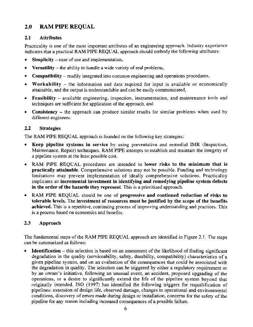
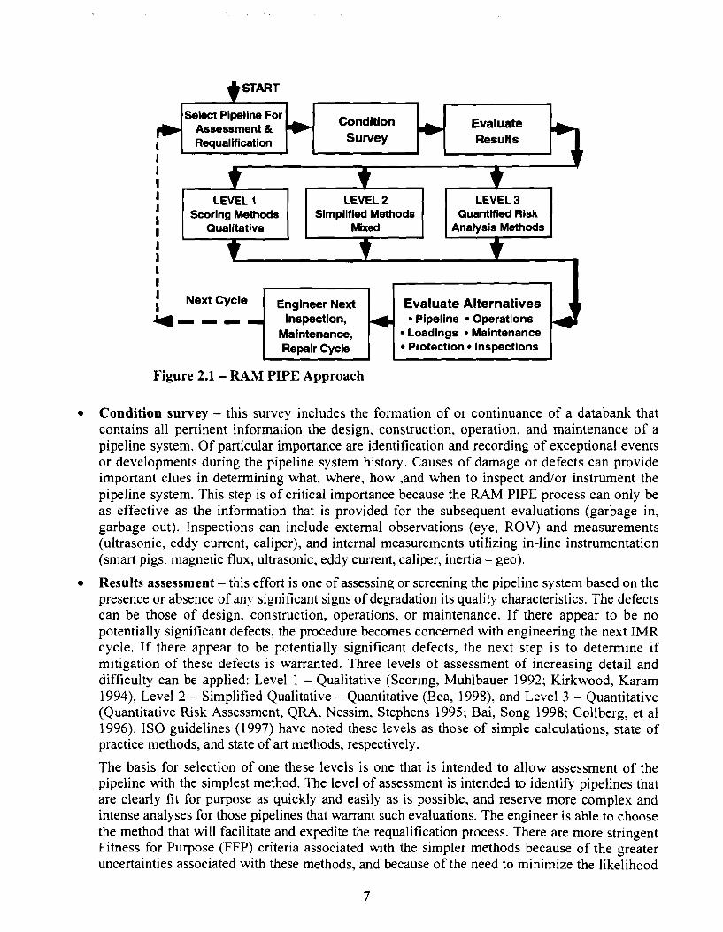
The fundamental steps of the RAM PIPE REQUAL approach are identified in Figure 2.1. The steps can be summarized as follows:
Identification - this selection is based on an assessment of the likelihood of finding significant degradation in the quality (serviceability, safety, durability, compatibility) characteristics of a given pipeline system, and on an evaluation of the consequences that could be associated with the degradation in quality. The selection can be triggered by either a regulatory requirement or by an owner's initiative, following an unusual event, an accident, proposed upgrading of the operations, or a desire to significantly extend the life of the pipeline system beyond that originally intended. I S 0 (1997) has identified the following triggers for requalification of pipelines: extension of design life, observed damage, changes in operational and environmental conditions, discovery of errors made during design or installation, concerns for the safety of the pipeline for any reason including increased consequences of a possible failure.
6
Select Pipellne For Assessment &
Condition
Requalification I I I I LEVEL 1 LEVEL 2 LEVEL 3 I Scoring hthods I Simplified Methods Quantified Risk
I Qualitative Mied Analysis Methods
I I I I I Next Cycle Engineer Next I Evaluate Alternatives -I--- Inspection, Pipeline Operations
Maintenance, Loadings Maintenance Repair Cycle Protection Inspections
Figure 2.1 - RAM PIPE Approach
Condition survey - this survey includes the formation of or continuance of a databank that contains all pertinent information the design, construction, operation, and maintenance of a pipeline system. Of particular importance are identification and recording of exceptional events or developments during the pipeline system history. Causes of damage or defects can provide important clues in determining what, where, how ,and when to inspect and/or instrument the pipeline system. This step is of critical importance because the RAM PIPE process can only be as effective as the information that is provided for the subsequent evaluations (garbage in, garbage out). Inspections can include external observations (eye, ROV) and measurements (ultrasonic, eddy current, caliper), and internal measurements utilizing in-line instrumentation (smart pigs: magnetic flux, ultrasonic, eddy current, caliper, inertia - geo).
Results assessment - this effort is one of assessing or screening the pipeline system based on the presence or absence of any significant signs of degradation its quality characteristics. The defects can be those of design, construction, operations, or maintenance. If there appear to be no potentially significant defects, the procedure becomes concerned with engineering the next IMR cycle. If there appear to be potentially significant defects, the next step is to determine if mitigation of these defects is warranted. Three levels of assessment of increasing detail and difficulty can be applied: Level 1 - Qualitative (Scoring, Muhlbauer 1992; Kirkwood, Karam 1994), Level 2 - Simplified Qualitative - Quantitative (Bea, 1998), and Level 3 - Quantitative (Quantitative Risk Assessment, QRA, Nessim, Stephens 1995; Bai, Song 1998; Collberg, et a1 1996). IS0 guidelines (1997) have noted these levels as those of simple calculations, state of practice methods, and state of art methods, respectively.
The basis for selection of one these levels is one that is intended to allow assessment of the pipeline with the simplest method. The level of assessment is intended to identify pipelines that are clearly fit for purpose as quickly and easily as is possible, and reserve more complex and intense analyses for those pipelines that warrant such evaluations. The engineer is able to choose the method that will facilitate and expedite the requalification process. There are more stringent Fitness for Purpose (FFP) criteria associated with the simpler methods because of the greater uncertainties associated with these methods, and because of the need to minimize the likelihood
of 'false positives' (pipelines identified to FFP that are not FFP).
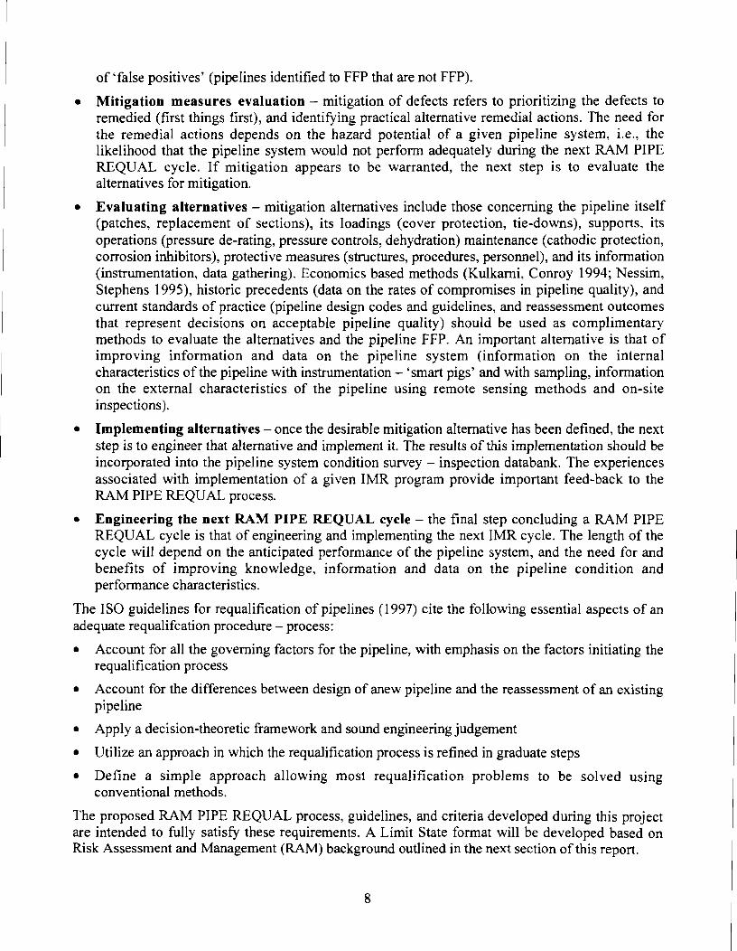
Mitigation measures evaluation - mitigation of defects refers to prioritizing the defects to remedied (first things first), and identifying practical alternative remedial actions. The need for the remedial actions depends on the hazard potential of a given pipeline system, i.e., the likelihood that the pipeline system would not perform adequately during the next RAM PIPE REQUAL cycle. If mitigation appears to be warranted, the next step is to evaluate the alternatives for mitigation.
Evaluating alternatives - mitigation alternatives include those concerning the pipeline itself (patches, replacement of sections), its loadings (cover protection, tie-downs), supports, its operations (pressure de-rating, pressure controls, dehydration) maintenance (cathodic protection, corrosion inhibitors), protective measures (structures, procedures, personnel), and its information (instrumentation, data gathering). Economics based methods (Kulkarni, Conroy 1994; Nessim, Stephens 1995), historic precedents (data on the rates of compromises in pipeline quality), and current standards of practice (pipeline design codes and guidelines, and reassessment outcomes that represent decisions on acceptable pipeline quality) should be used as complimentary methods to evaluate the alternatives and the pipeline FFP. An important alternative is that of improving information and data on the pipeline system (information on the internal characteristics of the pipeline with instrumentation - 'smart pigs' and with sampling, information on the external characteristics of the pipeline using remote sensing methods and on-site inspections).
Implementing alternatives -once the desirable mitigation alternative has been defined, the next step is to engineer that alternative and implement it. The results of this implementation should be incorporated into the pipeline system condition survey - inspection databank. The experiences associated with implementation of a given IMR program provide important feed-back to the RAM PIPE REQUAL process.
Engineering the next RAM PIPE REQUAL cycle - the final step concluding a RAM PIPE REQUAL cycle is that of engineering and implementing the next IMR cycle. The length of the cycle will depend on the anticipated performance of the pipeline system, and the need for and benefits of improving knowledge, information and data on the pipeline condition and performance characteristics.
The IS0 guidelines for requalification of pipelines (1997) cite the following essential aspects of an adequate requalifcation procedure - process:
Account for all the governing factors for the pipeline, with emphasis on the factors initiating the requalification process
Account for the differences between design of anew pipeline and the reassessment of an existing pipeline
Apply a decision-theoretic framework and sound engineering judgement
Utilize an approach in which the requalification process is refined in graduate steps
Define a simple approach allowing most requalification problems to be solved using conventional methods.
The proposed RAM PIPE REQUAL process, guidelines, and criteria developed during this project are intended to fully satisfy these requirements. A Limit State format will be developed based on Risk Assessment and Management (RAM) background outlined in the next section of this report.
3.0 Pipeline Requalification Formulations & Criteria
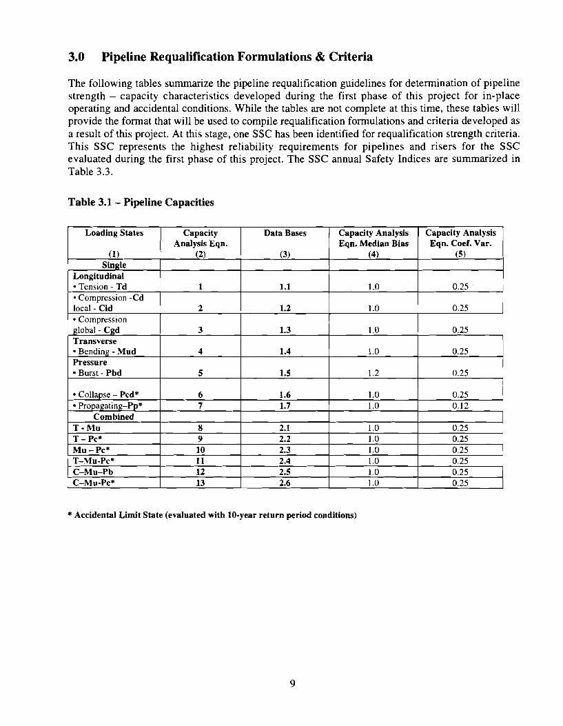
The following tables summarize the pipeline requalification guidelines for determination of pipeline strength - capacity characteristics developed during the first phase of this project for in-place operating and accidental conditions. While the tables are not complete at this time, these tables will provide the format that will be used to compile requalification formulations and criteria developed as a result of this project. At this stage, one SSC has been identified for requalification strength criteria. This SSC represents the highest reliability requirements for pipelines and risers for the SSC evaluated during the first phase of this project. The SSC annual Safety Indices are summarized in Table 3.3.
Table 3.1 - Pipeline Capacities
* Accidental Limit State (evaluated with 10-year return period conditions)
I
Loading States
(1) Single
Longitudinal Tension - Td Compression -Cd
local - Cld Compression
global - Cgd Transverse
Bending - Mud Pressure
Burst - Pbd
Collapse - Pcd*
Corn bined T - M U T - PC* MU - PC* T-MU-PC* C-M U-Pb C-MU-PC*
Capacity Analysis Eqn.
(2)
1
2
3
4
5
Capacity Analysis Eqn. Median Bias
(4)
1 .O
1 .O
1 .O
1 .O
1.2
Data Bases
(3)
1.1
1.2
1.3
1.4
1.5
8
9 10 11 12 13
Capacity Analysis Eqn. Coef. Var.
( 5 )
0.25
0.25
0.25
0.25
0.25
2.1 1 2.2
1 .O 1 .O
0.25 0.25 0.25 0.25
0.25 0.25
2.3 2.4 2.5 2.6
1 1 .O 1 .O 1 .O 1 .O
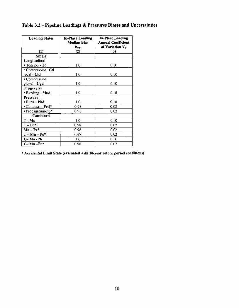
Table 3.2 - Pipeline Loadings & Pressures Biases and Uncertainties
Median Bias Annual Coefficient
* Accidental Limit State (evaluated with 10-year return period conditions)
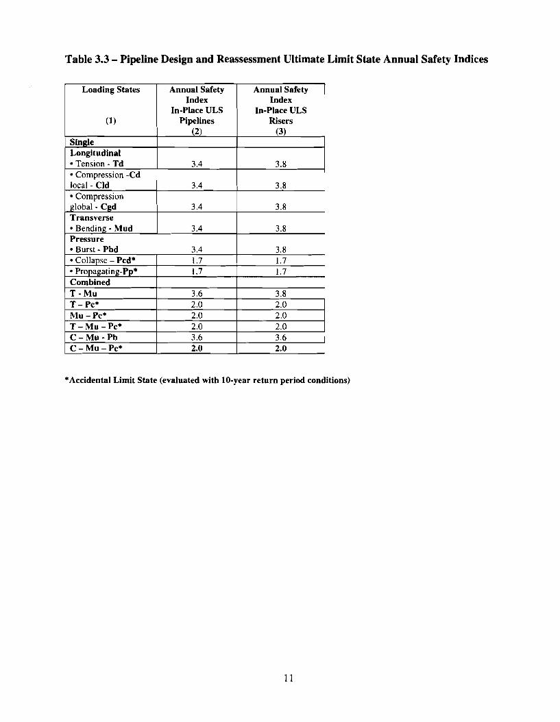
Table 3.3 - Pipeline Design and Reassessment Ultimate Limit State Annual Safety Indices
*Accidental Limit State (evaluated with 10-year return period conditions)
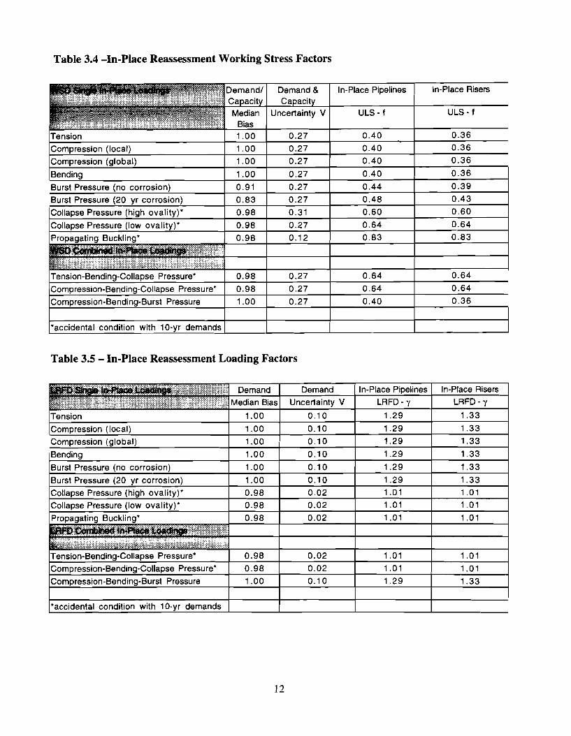
Table 3.4 -In-Place Reassessment Working Stress Factors
Table 3.5 - In-Place Reassessment Loading Factors
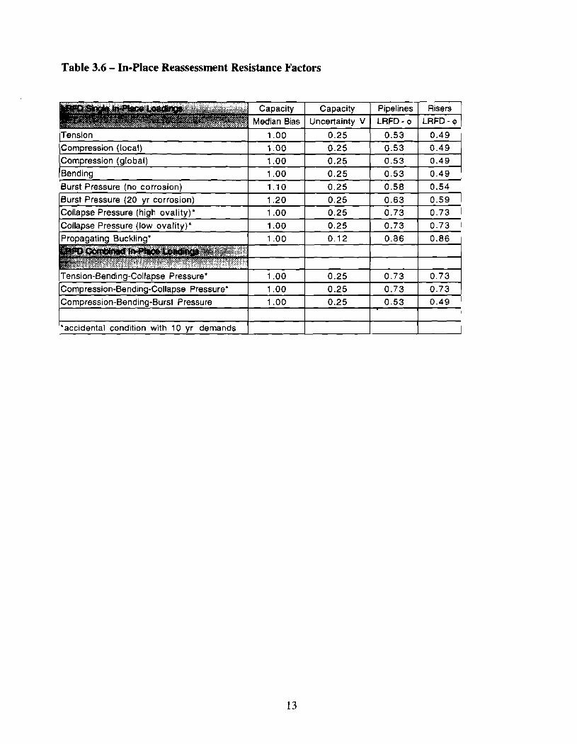
Table 3.6 - In-Place Reassessment Resistance Factors
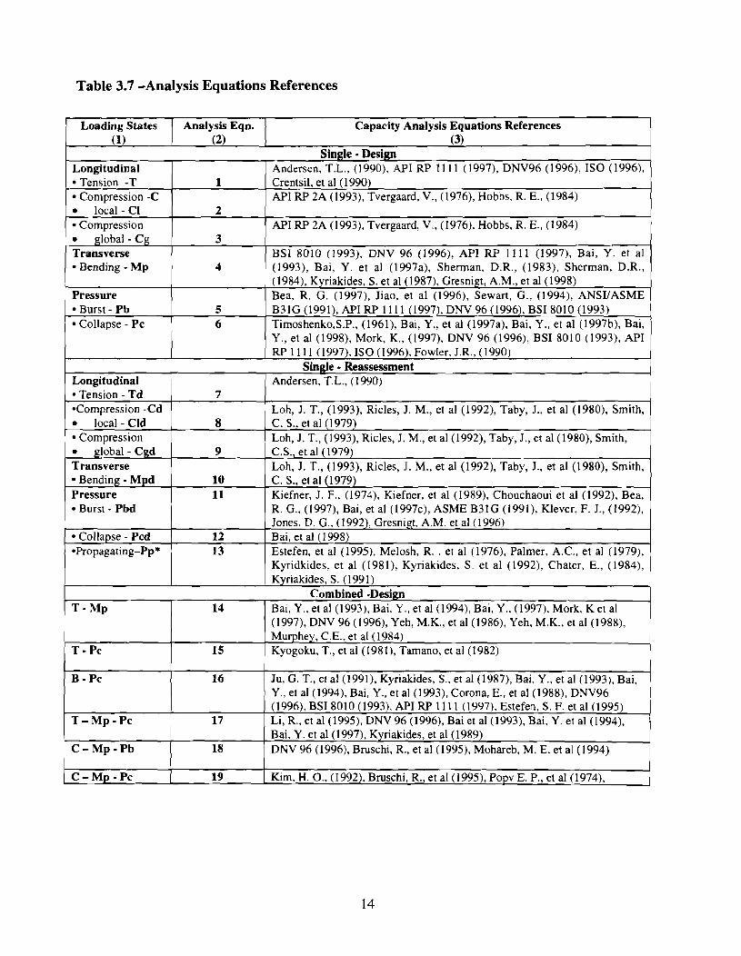
Table 3.7 -Analysis Equations References
1 Loading States ( Analysis Eqn. I Capacity Analysis Equations References (1)
~ e n s i o n -T
(2)
1 I Crentsil, et a1 (1990) -
2 API RP 2A (1993), Tvergaard, V., (1976), Hobbs, R. E., (1984)
3 BSI 8010 (1993), DNV 96 (1996), API RP 11 11 (1997), Bai, Y. et al
4 (1993), Bai, Y. et a1 (1997a), Sherman, D.R., (1983), Sherman, D.R.,
(3) Single - Desijgt
Compression -C 1 1 API RP 2A (1993), Tvergaard, V., (1976), Hobbs, R. E., (1984)
Pressure Burst - Pb Collapse - PC
Single - ~eassessrnent
Longitudinal
Longitudinal Tension - Td
I Andersen, T.L., (1990), API RP 11 11 (1997). DNV96 (1996), I S 0 (1996),
5 6
( Andersen, T.L., (1 990) 7
local - Cld 8
Bea, R. G. (1997), Jiao, et a1 (1996), Sewart, G., (1994), ANSYASME B31G (1991), API RP 11 11 (1997). DNV 96 (1996), BSI 8010 (1993) Timoshenko,S.P., (1961), Bal, Y., et a1 (1997a), Bai, Y., et a1 (1997b). Bai, Y., et a1 (1998), Mork, K., (1997), DNV 96 (1996), BSI 8010 (1993), API RP 11 11 (1997), I S 0 (1996), Fowler, J.R., (1990)
*Compression -Cd ( I Loh, J. T., (1993), Ricles, J. M., et a1 (1992), Taby, J., et al (1980), Smith,
Compression global - Cgd I 9 I C.S., et al (1979)
( Loh, J. T., (1993), Ricles, J. M., et a1 (1992), Taby, J., et a1 (1980), Smith,
Transverse Bending - Mpd 1 10 ( C. S., et a1 (1979)
] Loh, J. T., (1993), Ricles, J. M., et a1 (1992), Taby, J., et a1 (1980), Smith,
Pressure Burst - Pbd
Collapse - Pcd *Propagating-Pp*
11 ( Kiefner, J. F., (1974), Kiefner, et a1 (1989), Chouchaoui et a1 (1992), Bea,
B - PC
T - M p - P C
12 13
C - M p - P b
R. G., (1997), Bai, et al (1997c), ASME B31G (1991), Klever, F. J., (19921, Jones, D. G., (1992), Gresnigt, A.M. et a1 (1996) Bai, et a1 (1 998) Estefen, et a1 (1995), Melosh, R. , et al (1976). Palmer, A.C., et a1 (1979), Kyridkides. et a1 (1981), Kyriakides, S . et a1 (1992), Chater, E., (1984),
T - M p
T - PC
16
17
I I
Ju, G. T., et al (1991). Kyriakides, S., et a1 (1987), Bai. Y., et al (1993):~a; Y., et al (1994), Bai, Y., et a1 (1993), Corona, E., et a1 (1988), DNV96 (1996), BSI 8010 (1993), API RP 11 11 (1997). Estefen, S. F. et a1 (1995) Li, R., et a1 (199% DNV 96 (1996), Bai et a1 (1993), Bai, Y. et a1 (1994),
18
C - M p - P C
14
15
Bai, Y. et a1 (1997). Kyriakides, et a1 (1989) DNV 96 (1996), Bruschi, R., et a1 (1995), Mohareb, M. E. et a1 (1994)
19 ( Kim, H. 0.. (19921, Bmschi, R., et a1 (1995), Popv E. P., et a1 (1974),
Combined -Design Bai, Y., et a1 (1993), Bai, Y., et a1 (1994), Bai, Y., (1997), Mork, K et a1 (1997), DNV 96 (1996), Yeh, M.K., et a1 (1986), Yeh, M.K., et a1 (1988), Murphey, C.E., et a1 (1984) Kyogoku, T., et a1 (1981), Tarnano, et a1 (1982)