Embed Size (px)
Citation preview
Ramp Test Set
Operation Manual1002-0804-200
Issue-2
ATC-600A-2
OPERATION MANUAL
RAMP TEST SET
ATC-600A-2
PUBLISHED BY
Aerof lex
COPYRIGHT Aerof lex 2003 Al l r ights reserved. No part of this publ icat ion may be reproduced, stored in a retr ieval system, or transmitted in any form or by any means, electronic, mechanical, photocopying, recording or otherwise without the pr ior permission of the publ isher.
10200 West York / Wichita, Kansas 67215 U.S.A. / (316) 522-4981 / FAX (316) 524-2623
OPERATION MANUAL ATC-600A
Cable Statement:
A double shielded and proper ly terminated external inter face cable must be used with this equipment when interfacing with the ALTITUDE ENCODER INPUT Connector.
For cont inued EMC compliance, al l external cables, except suppl ied Antenna coaxial cable, must be 3 meters or less in length.
ESD Statement:
An Electrostat ic Discharge (ESD) to ei ther Front Panel Edge Meter may cause a momentary def lect ion of the Meter.
Nomenclature Statement:
In this manual the ATC-600A, ATC-600A Test Set, Test Set or Unit refers to the ATC-600A-2 Transponder and DME Test Set.

OPERATION MANUAL ATC-600A
THIS PAGE INTENTIONALLY LEFT BLANK.
OPERATION MANUAL ATC-600A
SAFETY FIRST: TO ALL OPERATIONS PERSONNEL
REFER ALL SERVICING OF UNIT TO QUALIFIED TECHNICAL PERSONNEL. THIS UNIT CONTAINS NO OPERATOR SERVICEABLE PARTS.
WARNING: USING THIS EQUIPMENT IN A MANNER OTHER THAN SPECIF IED BY THE ACCOMPANYING DOCUMENTATION MAY IMPAIR THE SAFETY PROTECTION PROVIDED BY THE EQUIPMENT.
CASE, COVER OR PANEL REMOVAL
Remov ing the Chass is Assembly f rom the Case Assembly exposes the operator to e lec t r i ca l hazards that can resu l t in e lec t r i ca l shock or equ ipment damage. Operate Tes t Set on ly w i th the Chass is Assembly ins ta l led in the Case Assembly .
SAFETY IDENTIFICATION IN TECHNICAL MANUAL
This manual uses the fo l lowing terms to draw at tent ion to poss ib le safe ty hazards , that may ex is t when operat ing th is equ ipment .
CAUTION: THIS TERM IDENTIF IES CONDITIONS OR ACTIVIT IES THAT, IF IGNORED, CAN RESULT IN EQUIPMENT OR PROPERTY DAMAGE (E .G. , F IRE) .
WARNING: THIS TERM IDENTIFIES CONDITIONS OR ACTIVIT IES THAT, IF IGNORED, CAN RESULT IN PERSONAL INJURY OR DEATH.
SAFETY SYMBOLS IN MANUALS AND ON UNITS
CAUTION: Refer to accompany ing documents . (Th is symbol re fers to spec i f i c CAUTIONS represented on the un i t . )
AC OR DC TERMINAL: Termina l that may supp ly or be supp l ied wi th ac or dc vo l tage.
DC TERMINAL: Termina l that may supp ly or be supp l ied wi th dc vo l tage.
AC TERMINAL: Termina l tha t may supp ly or be supp l ied wi th ac or a l te rnat ing vo l tage.
CAUTION: Refer to accompany ing documents . (Th is symbol re fers to spec i f i c CAUTIONS represented on the un i t . )
AC OR DC TERMINAL: Termina l that may supp ly or be supp l ied wi th ac or dc vo l tage.
DC TERMINAL: Termina l that may supp ly or be supp l ied wi th dc vo l tage.
AC TERMINAL: Termina l that may supp ly or be supp l ied wi th ac or a l te rnat ing vo l tage.
EQUIPMENT GROUNDING PRECAUTION
Improper ground ing o f equ ipment can resu l t in e lec t r i ca l shock .
USE OF PROBES
Check the spec i f i ca t ions for the max imum vo l tage, cur rent and power ra t ings o f any connec tor on the Tes t Set before connec t ing i t w i th a probe f rom a termina l dev ice. Be sure the termina l dev ice per forms wi th in these spec i f i ca t ions before us ing i t fo r measurement , to prevent e lec t r i ca l shock or damage to the equ ipment .
POWER CORDS
Avoid us ing power cords which are f rayed, broken or expose bare wi r ing when operat ing th is equ ipment .
USE RECOMMENDED FUSES ONLY
Use on ly fuses spec i f i ca l l y recommended for the equ ipment a t the spec i f ied cur rent and vo l tage ra t ings .
INTERNAL BATTERY
This un i t conta ins a N icke l Cadmium Bat tery , serv iceab le on ly by a qua l i f ied techn ic ian.
CAUTION: S IGNAL GENERATORS CAN BE A SOURCE OF ELECTROMAGNETIC INTERFERENCE (EMI ) TO COMMUNICATION RECEIVERS. SOME TRANSMITTED SIGNALS CAN CAUSE DISRUPTION AND INTERFERENCE TO COMMUNICATION SERVICES OUT TO A DISTANCE OF SEVERAL MILES. USERS OF THIS EQUIPMENT SHOULD SCRUTINIZE ANY OPERATION THAT RESULTS IN RADIATION OF A S IGNAL (DIRECTLY OR INDIRECTLY) AND SHOULD TAKE NECESSARY PRECAUTIONS TO AVOID POTENTIAL COMMUNICATION INTERFERENCE PROBLEMS.

OPERATION MANUAL ATC-600A
THIS PAGE INTENTIONALLY LEFT BLANK.

OPERATION MANUAL ATC-600A
RECORD OF REVISIONS
REV NO.
ISSUE DATE
DATE INSERTED
BY
REV NO.
ISSUE DATE
DATE INSERTED
BY

OPERATION MANUAL ATC-600A
THIS PAGE INTENTIONALLY LEFT BLANK.
OPERATION MANUAL ATC-600A
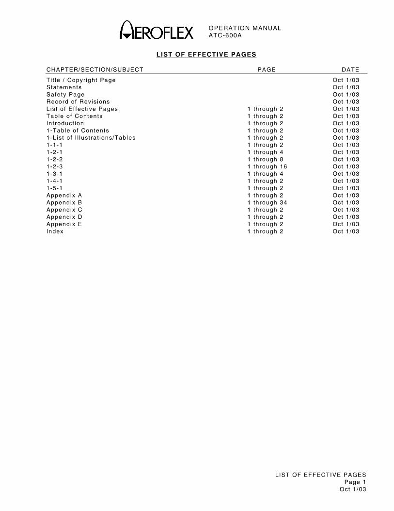
LIST OF EFFECTIVE PAGES Page 1
Oct 1 /03
LIST OF EFFECTIVE PAGES
CHAPTER/SECTION/SUBJECT PAGE DATE
Ti t le / Copyr ight Page Oct 1 /03 Statements Oct 1 /03 Safety Page Oct 1 /03 Record of Revis ions Oct 1 /03 L ist o f Ef fect ive Pages 1 through 2 Oct 1 /03 Table of Contents 1 through 2 Oct 1 /03 In t roduct ion 1 through 2 Oct 1 /03 1-Table of Contents 1 through 2 Oct 1 /03 1-L ist o f I l lust ra t ions/Tables 1 through 2 Oct 1 /03 1-1-1 1 through 2 Oct 1 /03 1-2-1 1 through 4 Oct 1 /03 1-2-2 1 through 8 Oct 1 /03 1-2-3 1 through 16 Oct 1 /03 1-3-1 1 through 4 Oct 1 /03 1-4-1 1 through 2 Oct 1 /03 1-5-1 1 through 2 Oct 1 /03 Appendix A 1 through 2 Oct 1 /03 Appendix B 1 through 34 Oct 1 /03 Appendix C 1 through 2 Oct 1 /03 Appendix D 1 through 2 Oct 1 /03 Appendix E 1 through 2 Oct 1 /03 Index 1 through 2 Oct 1 /03

OPERATION MANUAL ATC-600A
LIST OF EFFECTIVE PAGES Page 2
Oct 1 /03
THIS PAGE INTENTIONALLY LEFT BLANK.
OPERATION MANUAL ATC-600A
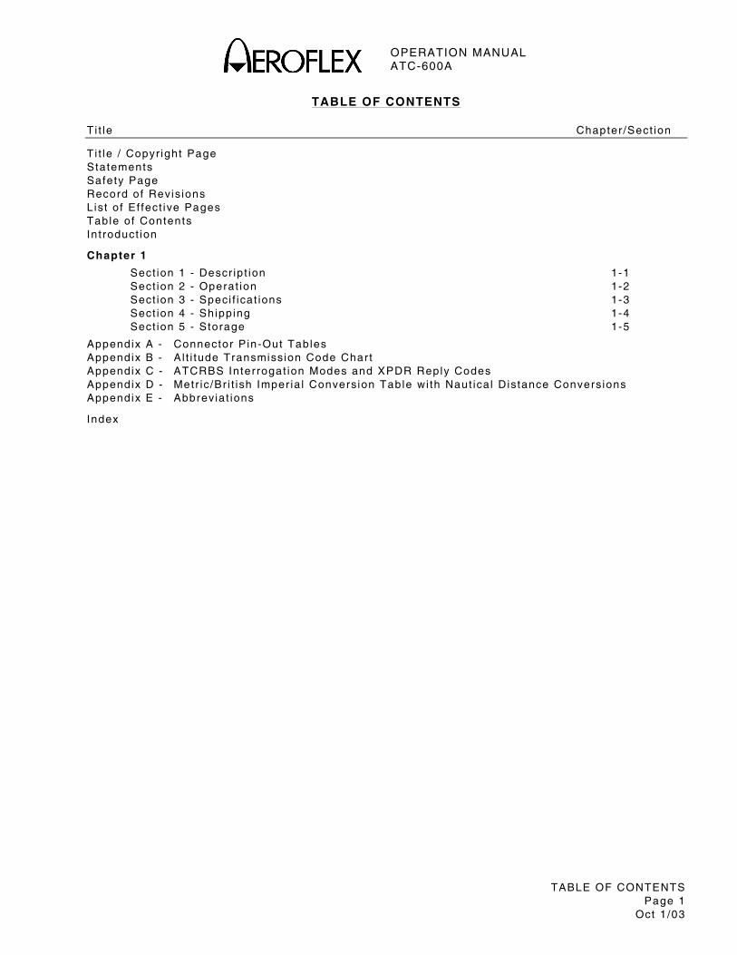
TABLE OF CONTENTS Page 1
Oct 1 /03
TABLE OF CONTENTS
Ti t le Chapter /Sect ion
T i t le / Copyr ight Page Statements Safety Page Record of Revis ions L ist o f Ef fect ive Pages Table of Contents In t roduct ion
Chapter 1
Sect ion 1 - Descr ip t ion 1-1 Sect ion 2 - Operat ion 1-2 Sect ion 3 - Speci f icat ions 1-3 Sect ion 4 - Shipping 1-4 Sect ion 5 - Storage 1-5
Appendix A - Connector P in-Out Tables Appendix B - A l t i tude Transmission Code Char t Appendix C - ATCRBS Interrogat ion Modes and XPDR Reply Codes Appendix D - Metr ic/Br i t ish Imper ia l Conversion Table wi th Naut ica l Distance Conversions Appendix E - Abbreviat ions
Index

OPERATION MANUAL ATC-600A
TABLE OF CONTENTS Page 2
Oct 1 /03
THIS PAGE INTENTIONALLY LEFT BLANK.
OPERATION MANUAL ATC-600A
INTRODUCTION Page 1
Oct 1 /03
INTRODUCTION - ATC-600A TEST SET
This manual conta ins ATC-600A operat ing inst ruct ions for Transponder and DME Test Systems. I t is st rongly recommended that personnel be thoroughly fami l iar wi th the contents of th is manual before at tempt ing to operate th is equipment .
Refer a l l servic ing of un i t to qual i f ied technica l personnel .
ORGANIZATION
This manual is d iv ided in to the fo l lowing Chapters and Sect ions:
CHAPTER 1 - OPERATION
Sect ion 1 - DESCRIPTION (descr ip t ion of the ATC-600A)
Sect ion 2 - OPERATION ( insta l la t ion; descr ip t ion of contro ls, connectors and ind icators; and genera l operat ing procedures)
Sect ion 3 - SPECIFICATIONS
Sect ion 4 - SHIPPING
Sect ion 5 - STORAGE

OPERATION MANUAL ATC-600A
INTRODUCTION Page 2
Oct 1 /03
THIS PAGE INTENTIONALLY LEFT BLANK.
OPERATION MANUAL ATC-600A
1-TABLE OF CONTENTS Page 1
Oct 1 /03
CHAPTER ONE
ATC-600A TEST SET
OPERATION MANUAL
TABLE OF CONTENTS
Ti t le Chapter /Sect ion/Subject Page
SECTION 1 – DESCRIPTION 1-1
1 . Genera l Descr ip t ion and Capabi l i t ies 1-1-1 1 1 .1 Descr ip t ion 1-1-1 1 1 .2 Funct ional Capabi l i t ies 1-1-1 1
SECTION 2 – OPERATION 1-2
1 . Insta l la t ion 1-2-1 1 1 .1 Genera l 1-2-1 1 1 .2 Bat tery Operat ion 1-2-1 1 1 .3 Bat tery Charg ing 1-2-1 1 1 .4 Safety Precaut ions 1-2-1 1
1.4.1 Complying wi th Inst ruct ions 1-2-1 1 1.4.2 Grounding Power Cord 1-2-1 1 1.4.3 Operat ing Safety 1-2-1 1 1.4.4 CAUTION and WARNING Labels 1-2-1 2
1 .5 AC Power Requi rements 1-2-1 2 1 .6 Bat tery Recharg ing 1-2-1 2 1 .7 Bench Operat ion 1-2-1 3 1 .8 External Cleaning 1-2-1 3 2. Contro ls, Connectors And Ind icators 1-2-2 2 2 .1 Front Panel 1-2-2 3 2 .2 Rear Panel 1-2-2 7 3. Genera l Operat ing Procedures 1-2-3 1 3 .1 Genera l 1-2-3 1 3 .2 Ramp Operat ion Equipment 1-2-3 1 3 .3 Bench Operat ion Equipment 1-2-3 1 3 .4 Bat tery Parameters 1-2-3 1 3 .5 Transponder Operat ion Test Equipment Setup 1-2-3 3 3 .6 Transponder Operat ion Tests 1-2-3 3
3.6.1 Pi lo t ’s Code 1-2-3 3 3.6.2 Al t i tude Code 1-2-3 4 3.6.3 Peak Transponder Power 1-2-3 4 3.6.4 Transponder Frequency 1-2-3 5 3.6.5 Percent Reply 1-2-3 5 3.6.6 SLS Operat ion 1-2-3 6 3.6.7 IDENT (XPDR) Pulse Output 1-2-3 6 3.6.8 Inva l id ALT Ind icator 1-2-3 7 3.6.9 XPDR Receiver-Decoder L imi ts 1-2-3 7 3.6.10 Transponder Pulse Spacing 1-2-3 8 3.6.11 Receiver Sensi t iv i ty 1-2-3 8
3 .7 DME Operat ion Test Equipment Setup 1-2-3 9
OPERATION MANUAL ATC-600A
1-TABLE OF CONTENTS Page 2
Oct 1 /03
T i t le Chapter /Sect ion/Subject Page
3 .8 DME Operat ion Tests 1-2-3 9 3.8.1 DME Range or Distance Operat ion 1-2-3 9 3.8.2 DME Veloci ty Operat ion 1-2-3 10 3.8.3 DME Transmi t ted PRF 1-2-3 10 3.8.4 Transmi t ter Peak Power and Frequency 1-2-3 11 3.8.5 IDENT Tone 1-2-3 11 3.8.6 Percent Reply 1-2-3 12 3.8.7 Squi t ter Lock-Out 1-2-3 12 3.8.8 17Y Channel Operat ion 1-2-3 13 3.8.9 DME ILS Channel Operat ion 1-2-3 13
3 .9 Encoding Al t imeter Operat ion Test Equipment Setup 1-2-3 14 3 .10 Encoding Al t imeter Tests 1-2-3 15
3.10.1 Al t i tude Disp lay 1-2-3 15
SECTION 3 – SPECIFICATIONS 1-3
1 . ATC-600A Speci f icat ions 1-3-1 1 1 .1 Transponder 1-3-1 1 1 .2 DME 1-3-1 2 1 .3 Bat tery Operat ion 1-3-1 3 1 .4 ac Power Requi rements 1-3-1 3 1 .5 Fuse Requi rements 1-3-1 3 1 .6 Safety 1-3-1 3 1 .7 Operat ional Envi ronmenta l Considerat ions 1-3-1 3 1 .8 Physica l Character ist ics 1-3-1 3
SECTION 4 – SHIPPING 1-4
1 . Shipping Test Sets 1-4-1 1 1 .1 In format ion 1-4-1 1 1 .2 Repacking Procedure 1-4-1 1
SECTION 5 – STORAGE 1-5
1 . Stor ing Test Sets 1-5-1 1
OPERATION MANUAL ATC-600A
1-LIST OF ILLUSTRATIONS/TABLES Page 1
Oct 1 /03
LIST OF ILLUSTRATIONS
T i t le Chapter /Sect ion/Subject Page
Bat tery Recharg ing 1-2-1 3 ATC-600A Front and Rear Panels 1-2-2 1 Al t i tude Pulse Posi t ion Assignment Char t (ARINC 532D) 1-2-2 8 Ramp Operat ion Test Equipment Setup 1-2-3 2 Repacking Procedure 1-4-1 2
LIST OF TABLES
T i t le Chapter /Sect ion/Subject Page
Speci f ied Fuse Rat ings 1-2-1 2 DME Frequency/Spacing Assignments 1-2-2 5 Encoder Connector P in Assignments 1-2-3 14

OPERATION MANUAL ATC-600A
1-LIST OF ILLUSTRATIONS/TABLES Page 2
Oct 1 /03
THIS PAGE INTENTIONALLY LEFT BLANK.
OPERATION MANUAL ATC-600A
1-1-1 Page 1
Oct 1 /03
SECTION 1 - DESCRIPTION
1. GENERAL DESCRIPTION AND CAPABILITIES
1.1 DESCRIPTION
The ATC-600A is a precis ion s imulator that enables one person to funct ional i ty test a i rborne t ransponder (XPDR) and d istance measur ing equipment (DME) systems wi thout removing the systems f rom the a i rcraf t .
The Test Set conta ins bu i l t - in s ignal generators and modulators for XPDR and se lected DME f requencies. For ramp operat ion, the RF output is coupled to the a i rborne equipment by a remote t r ipod mounted antenna system. For bench operat ion, coaxia l cables are requi red between the Test Set and UUT.
1.2 FUNCTIONAL CAPABILITIES
The ATC-600A has the fo l lowing features and capabi l i t ies:
The type of t ransponder in ter rogat ion desi red is se lected f rom Modes A/C ALT and A/C CODE. The A/C ALT Mode d isp lays the a i t i tude code. The A/C CODE Mode d isp lays the p i lo t ’s code. Code pulses and the numer ica l readout are d isp layed simul taneously in a l l modes.
A FREQ/PWR Meter ind icates peak RF power and the t ransmi t ter f requency of the UUT. The XPDR % RPLY/DME PRF MTR ind icates XPDR percent rep ly and DME in ter rogat ion pulse repet i t ion f requency (PRF).
The In ter rogat ion Spacing Contro l a l lows precise checking of the XPDR input pu lse decoder gate. The Framing Pulse Spacing Contro l a l lows checking of the F2 pulse width and posi t ion re la t ive to F1. The Al t i tude Encoder Input Connector a l lows a l t i tude d isp lay f rom an encoding a l t imeter wi thout a t ransponder .
The DME f ixed range is var iab le f rom 0 to 399.0 NM, wi th ve loci ty f rom 50 to 2400 knots. X Channel (108.00 or 108.10 MHz pai red channel ) and Y Channel (108.05 MHz pai red channel ) are provided.
A NICAD bat tery and bui l t - in charg ing system permi t complete ly por tab le operat ion for up to 2 hours cont inuous duty. Any t ime the Test Set is p lugged to an ac l ine, the bat tery is be ing charged. In bat tery operat ion, an automat ic t imer turns the Test Set o f f a f ter 7 to 10 minutes. The Test Set can be recycled by pressing the PWR/BAT Swi tch to the BAT posi t ion.

OPERATION MANUAL ATC-600A
1-1-1 Page 2
Oct 1 /03
THIS PAGE INTENTIONALLY LEFT BLANK.
OPERATION MANUAL ATC-600A
1-2-1 Page 1
Oct 1 /03
SECTION 2 - OPERATION
1. INSTALLATION
1.1 GENERAL
The Test Set is powered by an in ternal bat tery. The Test Set conta ins a bat tery charg ing ci rcu i t which recharges the bat tery when the Test Set isconnected to ac power.
NOTE: The Test Set can operate cont inuously on ac power for servic ing and/or bench tests.
Refer to 1-2-2, F igure 2 for locat ion of contro ls, connectors or ind icators.
1.2 BATTERY OPERATION
The in ternal bat tery (NICAD) is equipped to power the Test Set for 2 hours of cont inuous use, a f ter which t ime, the Test Set bat tery needs recharg ing.
When the BAT Test Swi tch is pressed, the XPDR % RPLY/DME PRF MTR disp lays the bat tery vo l tage. Normal bat tery charged condi t ion is ind icated wi th in the whi te band. Lef t edge of the whi te band ind icates 12.1 V. An automat ic low vo l tage cutof f c i rcu i t turns the Test Set OFF when the bat tery vo l tage drops under approximate ly 11.4 V.
The Test Set conta ins an automat ic t ime-out to conserve power. An automat ic t imer turns the Test Set OFF af ter 7 to 10 minutes (on ly when using bat tery power) . The Test Set can be recycled by pressing the PWR/BAT Swi tch to the BAT posi t ion.
1.3 BATTERY CHARGING
The bat tery charger operates whenever ac power is appl ied to the Test Set . The bat tery should be charged every three months (min imum).
NOTE: Overn ight charg ing is recommended.
1.4 SAFETY PRECAUTIONS
The fo l lowing safety precaut ions must be observed dur ing insta l la t ion and operat ion. IFR assumes no l iab i l i ty for fa i lure to comply wi th any safety precaut ion out l ined in th is manual .
1 .4.1 Complying with Instruct ions
Insta l la t ion/operat ing personnel should at tempt to insta l l or operate the Test Set on ly af ter reading and complying wi th inst ruct ions conta ined in th is manual . A l l procedures conta ined in th is manual must be per formed in exact sequence and manner descr ibed.
1.4.2 Grounding Power Cord
WARNING: USING A THREE-PRONG TO TWO-PRONG ADAPTER PLUG CREATES A SHOCK HAZARD BETWEEN THE CHASSIS AND ELECTRICAL GROUND.
For ac operat ion, the power cord, equipped wi th standard three-prong p lug, must be connected to a proper ly grounded three-prong receptacle. I t is the customer ’s responsib i l i ty to :
Have a qual i f ied e lect r ic ian check receptacle(s) for proper grounding.
Replace any standard two-prong receptacle(s) wi th proper ly grounded three-prong receptacle(s) .
1.4.3 Operat ing Safety
Due to potent ia l for e lect r ica l shock wi th in test equipment , the Chassis Assembly must remain insta l led in the Case Assembly. Bat tery rep lacement must on ly be per formed by qual i f ied service technic ians.
1.4.4 CAUTION and WARNING Labels
Exercise ext reme care when per forming operat ions preceded by a CAUTION or WARNING label . CAUTION labels appear where possib i l i ty o f damage to equipment exists. WARNING labels denote condi t ions where bodi ly in jury or death may resul t .
OPERATION MANUAL ATC-600A
1-2-1 Page 2
Oct 1 /03
1.5 AC POWER REQUIREMENTS
The Test Set operates over a vo l tage range of 100 to 120 VAC at 60 Hz or 220 to 240 VAC at 50 Hz accord ing to VOLTAGE SELECT Swi tch set t ing.
The speci f ied fuse rat ings are l is ted in 1-2-1, Table 1.
CAUTION: FOR CONTINUOUS PROTECTION AGAINST FIRE, REPLACE ONLY WITH FUSES OF THE SPECIFIED VOLTAGE AND CURRENT RATINGS.
INPUT VOLTAGE F1 AND F2 FUSES
100 to 120 VAC 1.0 A, 250 V
Fast B lo (Type F)
( IFR PN: 5106-4501-000)
(1.25 in , AGC Glass)
220 to 240 VAC 0.5 A, 250 V
Fast B lo (Type F)
( IFR PN: 5106-0000-016)
(1.25 in , AGC Glass)
Speci f ied Fuse Rat ings Table 1
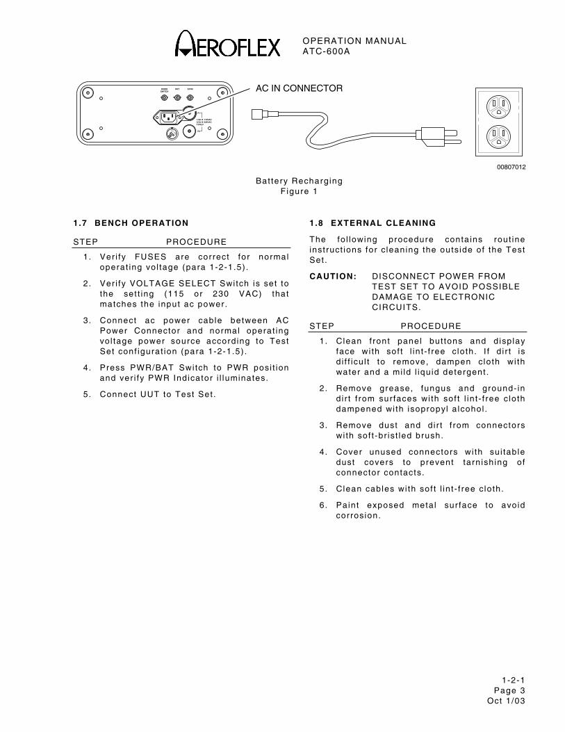
1.6 BATTERY RECHARGING
Refer to 1-2-1, F igure 1.
STEP PROCEDURE
1. Ver i fy FUSES are correct for normal operat ing vo l tage (para 1-2-1.5) .
2 . Ver i fy VOLTAGE SELECT Swi tch is set to the set t ing (115 or 230 VAC) that matches the input ac power.
3 . Connect ac power cable between AC Power Connector and normal operat ing vo l tage power source, accord ing to Test Set conf igurat ion (para 1-2-1.5) .
NOTE: The bat tery charger operates whenever ac power is appl ied to the Test Set .
4 . A l low severa l hours for bat tery charge or unt i l the XPDR % RPLY/DME PRF MTR disp lays the bat tery vo l tage wel l wi th in the whi te band.
NOTE: Overn ight charg ing is recommended.
OPERATION MANUAL ATC-600A
1-2-1 Page 3
Oct 1 /03
1.0A @ 110VAC0.5A @ 220VAC
F2
TYPE F
F1
DIODESWITCH
DET
SYNC
115 230
S
00807012
AC IN CONNECTOR
Bat tery Recharg ing F igure 1
1.7 BENCH OPERATION
STEP PROCEDURE
1. Ver i fy FUSES are correct for normal operat ing vo l tage (para 1-2-1.5) .
2 . Ver i fy VOLTAGE SELECT Swi tch is set to the set t ing (115 or 230 VAC) that matches the input ac power.
3 . Connect ac power cable between AC Power Connector and normal operat ing vo l tage power source accord ing to Test Set conf igurat ion (para 1-2-1.5) .
4 . Press PWR/BAT Swi tch to PWR posi t ion and ver i fy PWR Indicator i l luminates.
5 . Connect UUT to Test Set .
1.8 EXTERNAL CLEANING
The fo l lowing procedure conta ins rout ine inst ruct ions for c leaning the outside of the Test Set .
CAUTION: DISCONNECT POWER FROM TEST SET TO AVOID POSSIBLE DAMAGE TO ELECTRONIC CIRCUITS.
STEP PROCEDURE
1. Clean f ront panel but tons and d isp lay face wi th sof t l in t - f ree c lo th. I f d i r t is d i f f icu l t to remove, dampen clo th wi th water and a mi ld l iqu id detergent .
2 . Remove grease, fungus and ground- in d i r t f rom sur faces wi th sof t l in t - f ree c lo th dampened wi th isopropyl a lcohol .
3 . Remove dust and d i r t f rom connectors wi th sof t -br ist led brush.
4 . Cover unused connectors wi th su i tab le dust covers to prevent tarn ish ing of connector contacts.
5 . Clean cables wi th sof t l in t - f ree c lo th.
6 . Paint exposed meta l sur face to avoid corrosion.

OPERATION MANUAL ATC-600A
1-2-1 Page 4
Oct 1 /03
THIS PAGE INTENTIONALLY LEFT BLANK.
OPERATION MANUAL ATC-600A
1-2-2 Page 1
Oct 1 /03
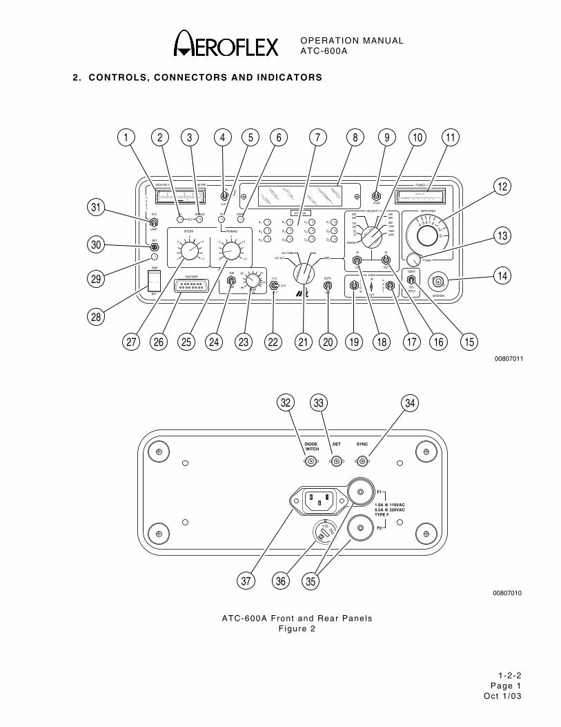
2. CONTROLS, CONNECTORS AND INDICATORS
0 10 20 30
600 20 40 80 100%
.10 1.5 2 4 6
WATTS x 100
158 10
ATC-600A
00807011
XMTR FREQ
-1
GAIN
FRAMING
-.5+1-1
PWR
ENCODER0dB
-9dB
INTERR
BAT
LAMP
-.4
SYS
TSET
NO
+.4
0
-.2
0
INVALID
ALT
F2
0-300
XPDR RPLY DME PRF
0-30
+.5 A/C ALT DME
18 XXPDR
SIG 17 Y
69
66
73
7717 X
OFF
SQTR
WOUT
LO
S
OL
SLEWIN
T REPLY
F
SA
OUT
50%
IDENT
A/C CODE
B
B
B
+.2 3A
2A
IDENT
1A
3
2
3
2
C
C
A
3D
2D
11 C 1D
FREQ
1505075
RANGE
HI
100
200300
VELOCITY
1200
IN
16002400
800
600400
-3-4-2
POWER
ANTENNA
+1+3
+2
0
BAT
12
13
14
21 20 19 18 17 16 15222324252627
28
29
30
31
7 8 109 11654321
1.0A @ 110VAC0.5A @ 220VAC
F2
TYPE F
F1
DIODESWITCH
DET
SYNC
00807010
115 230
S
32 33 34
353637
ATC-600A Front and Rear Panels
F igure 2
OPERATION MANUAL ATC-600A
1-2-2 Page 2
Oct 1 /03
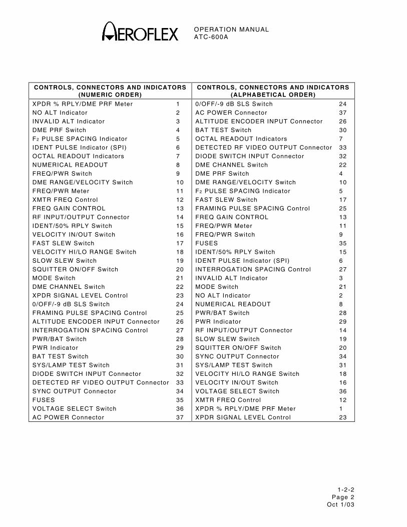
CONTROLS, CONNECTORS AND INDICATORS (NUMERIC ORDER)
CONTROLS, CONNECTORS AND INDICATORS (ALPHABETICAL ORDER)
XPDR % RPLY/DME PRF Meter 1
NO ALT Indicator 2
INVALID ALT Indicator 3
DME PRF Switch 4
F2 PULSE SPACING Indicator 5
IDENT PULSE Indicator (SPI) 6
OCTAL READOUT Indicators 7
NUMERICAL READOUT 8
FREQ/PWR Switch 9
DME RANGE/VELOCITY Switch 10
FREQ/PWR Meter 11
XMTR FREQ Control 12
FREQ GAIN CONTROL 13
RF INPUT/OUTPUT Connector 14
IDENT/50% RPLY Switch 15
VELOCITY IN/OUT Switch 16
FAST SLEW Switch 17
VELOCITY HI/LO RANGE Switch 18
SLOW SLEW Switch 19
SQUITTER ON/OFF Switch 20
MODE Switch 21
DME CHANNEL Switch 22
XPDR SIGNAL LEVEL Control 23
0/OFF/-9 dB SLS Switch 24
FRAMING PULSE SPACING Control 25
ALTITUDE ENCODER INPUT Connector 26
INTERROGATION SPACING Control 27
PWR/BAT Switch 28
PWR Indicator 29
BAT TEST Switch 30
SYS/LAMP TEST Switch 31
DIODE SWITCH INPUT Connector 32
DETECTED RF VIDEO OUTPUT Connector 33
SYNC OUTPUT Connector 34
FUSES 35
VOLTAGE SELECT Switch 36
AC POWER Connector 37
0/OFF/-9 dB SLS Switch 24
AC POWER Connector 37
ALTITUDE ENCODER INPUT Connector 26
BAT TEST Switch 30
OCTAL READOUT Indicators 7
DETECTED RF VIDEO OUTPUT Connector 33
DIODE SWITCH INPUT Connector 32
DME CHANNEL Switch 22
DME PRF Switch 4
DME RANGE/VELOCITY Switch 10
F2 PULSE SPACING Indicator 5
FAST SLEW Switch 17
FRAMING PULSE SPACING Control 25
FREQ GAIN CONTROL 13
FREQ/PWR Meter 11
FREQ/PWR Switch 9
FUSES 35
IDENT/50% RPLY Switch 15
IDENT PULSE Indicator (SPI) 6
INTERROGATION SPACING Control 27
INVALID ALT Indicator 3
MODE Switch 21
NO ALT Indicator 2
NUMERICAL READOUT 8
PWR/BAT Switch 28
PWR Indicator 29
RF INPUT/OUTPUT Connector 14
SLOW SLEW Switch 19
SQUITTER ON/OFF Switch 20
SYNC OUTPUT Connector 34
SYS/LAMP TEST Switch 31
VELOCITY HI/LO RANGE Switch 18
VELOCITY IN/OUT Switch 16
VOLTAGE SELECT Switch 36
XMTR FREQ Control 12
XPDR % RPLY/DME PRF Meter 1
XPDR SIGNAL LEVEL Control 23
OPERATION MANUAL ATC-600A
1-2-2 Page 3
Oct 1 /03
2.1 FRONT PANEL
Refer to 1-2-2, F igure 2.
ITEM DESCRIPTION
1. XPDR % RPLY/DME PRF Meter
In Transponder Modes (A/C ALT , A/C CODE and A set t ings of MODE Swi tch) , ind icates the percent rep ly o f the Transponder ( in the operat ion mode se lected) .
In DME Mode (DME set t ing of MODE Swi tch) , ind icates the Pulse Repet i t ion Frequency (PRF) of the DME under test .
2 . NO ALT Ind icator
When l i t , ind icates No Al t i tude pulses are present between F1 and F2 of the Transponder ’s a l t i tude rep ly.
3 . INVALID ALT Indicator
When l i t , ind icates a received a l t i tude code has an unassigned combinat ion of codes.
The condi t ions to VALID Al t i tude in format ion are the presence of a t least one of the C Pulses (C1, C2 or C4) and never C1 and C4 ON at the same t ime.
4 . F2 PULSE SPACING Indicator
When l i t , the FRAMING PULSE SPACING Contro l is posi t ioned to a t ime when no par t o f the F2 pu lse is present . I f the FRAMING PULSE SPACING Contro l is a t or near zero, and the F2 PULSE SPACING Indicator is l i t , the 2nd f raming pulse in the Transponder rep ly is improper ly spaced, is too narrow for normal operat ion or is absent a l together .
NOTE: I f F2 is out o f posi t ion, a l l o ther rep ly pu lses between F1 and F2 may be skewed out o f posi t ion.
ITEM DESCRIPTION
5. DME PRF Swi tch
Selects the fu l l sca le range ( in PRF) of the XPDR % RPLY/DME PRF Meter :
0-30 is used for t rack rates.
0-300 is used for search rates.
NOTE: The in ter rogat ion Pulse Repet i t ion Frequency (PRF) is f ixed at 235 pps. (Only in Transponder Mode.)
6 . IDENT PULSE Indicator
When l i t , ind icates the Ident Pulse (SPI) is present in the reply.
When the Test Set is in A/C ALT Mode, the Ident Pulse is pa i red wi th the D4 pu lse.
NOTE: Act ive in Transponder Modes only.
7 . NUMERICAL Readout
Disp lays p i lo t ’s code (as set in to the Contro l Head) when the MODE Swi tch is set to A/C CODE .
Disp lays a l t i tude f rom -1.0 thousand to +126.7 thousand feet when the MODE Swi tch is set to A/C ALT .
Disp lays a l t i tude of Encoding Al t imeter when an Encoding Al t imeter is connected to the ALTITUDE ENCODER INPUT Connector .
Disp lays range in naut ica l mi les when the MODE Swi tch is set to DME.
8. OCTAL READOUT Indicators
Ind icates which pulses are act ivat ing the NUMERICAL Readout when the MODE Swi tch is set to A/C ALT .
NOTE: The a l t i tude code is a Gray Daytex code.
Ind icates p i lo t ’s code (set in the Transponder Contro l Head) in b inary form when MODE Swi tch is set to A/C CODE or A .
NOTE: Act ive in Transponder Modes only.
OPERATION MANUAL ATC-600A
1-2-2 Page 4
Oct 1 /03
ITEM DESCRIPTION
9. DME RANGE/VELOCITY Swi tch
RANGE y ie lds f ixed range rep l ies. (Star t ing range is set wi th the FAST SLEW Swi tch and/or SLOW SLEW Switch. )
VELOCITY is d iv ided in to two crysta l -cont ro l led steps (50/75 , 100/150 , e tc. ) . (The VELOCITY HI /LO RANGE Switch determines which of the two va lues to be se lected in VELOCITY mode.) (Star t ing range is set wi th the FAST SLEW Swi tch and/or SLOW SLEW Switch. )
NOTE: The FAST SLEW Swi tch and SLOW SLEW Swi tch operate in VELOCITY Mode in acuta l system range increments of approximate ly 0 .025 NM. However , the ve loci ty range is d isp layed on the NUMERICAL Readout in 0 .1 NM steps only.
10. FREQ/PWR Swi tch
FREQ swi tches FREQ/PWR Meter to d isp lay f requency deviat ion.
PWR swi tches FREQ/PWR Meter to d isp lay peak power.
11. FREQ/PWR Meter
When the FREQ/PWR Swi tch is set to PWR , FREQ/PWR Meter d isp lays peak power f rom 0 to 1.5 kW ( i f test antenna spacing f rom the a i rcraf t is correct or a 34 dB pad and coaxia l cable are used) .
NOTE: The 34 dB pad and coaxia l cable are not suppl ied wi th the uni t .
When the FREQ/PWR Swi tch is set to FREQ , FREQ/PWR Meter d isp lays f requency deviat ion of the UUT f rom desi red f requency.
ITEM DESCRIPTION
12. XMTR FREQ Contro l
Used to tune the FREQ/PWR Meter needle for maximum def lect ion.
In Transponder operat ion, f requency deviat ion ( f rom 1090 MHz) of the UUT is read d i rect ly f rom the XMTR FREQ Contro l in MHz.
In DME operat ion, f requency deviat ion ( f rom 1041 MHz) of the UUT is read d i rect ly f rom the XMTR FREQ Contro l in MHz.
NOTE: The Plus (+) and minus ( - ) s igns on the XMTR FREQ Contro l are reversed in DME operat ion (posi t ive va lues are le f t o f zero and negat ive va lues are r ight o f zero) .
13. FREQ GAIN CONTROL
Regulates amount o f current to the FREQ/PWR Meter to enable a l l s ignals (weak and powerfu l ) to d isp lay equal ly.
14. RF INPUT/OUTPUT Connector
Used to connect a remote test antenna ( ramp operat ion) or a 34 dB pad and coaxia l cable (bench operat ion) .
NOTE: The 34 dB pad and coaxia l cable are not suppl ied wi th the uni t .
15. IDENT/50% RPLY Swi tch
IDENT sends 1350 Hz tone to the DME.
50% RPLY de le tes 50% of the rep l ies to a DME on a 50-50 basis.
16. VELOCITY IN/OUT Swi tch
Selects the d i rect ion of the rep l ied range in VELOCITY Mode:
IN - towards the ground stat ion.
OUT - away f rom the ground stat ion.
NOTE: When the inbound range reaches 0.0 NM, the range instant ly changes to 399.0 NM and cont inues inbound. When the outbound range reaches 399.0 NM, the range instant ly changes to 0.0 NM and cont inues outbound.
OPERATION MANUAL ATC-600A
1-2-2 Page 5
Oct 1 /03
ITEM DESCRIPTION
17. FAST SLEW Swi tch
Sets DME repl ied d istance or range approximate ly 10 t imes faster than the SLOW SLEW Swi tch. Range is s lewed f rom 0.0 to 399.0 NM in approximate ly 10.0 NM steps ( inbound or outbound) .
18. VELOCITY HI /LO RANGE Switch
Determines which of the two crysta l -cont ro l led increments (50/75 , 100/150 , e tc. ) se lected by the DME RANGE/VELOCITY Swi tch to implement :
HI se lects the greater o f the two va lues.
LO se lects the lesser of the two va lues.
19. SLOW SLEW Swi tch
Sets DME repl ied d istance or range approximate ly 10 t imes slower than the SLOW SLEW Swi tch. Range is s lewed f rom 0.0 to 399.0 NM in 1.0 NM steps ( inbound or outbound) .
20. SQUITTER ON/OFF Swi tch
SQTR turns squi t ter ON in DME Operat ion.
OFF turns squi t ter OFF in DME Operat ion.
NOTE: Squi t ter is f ixed to an average of 2700 PRF at a random rate.
21. MODE Swi tch
Determines which Transponder Mode (AC ALT , A/C CODE or A ) or DME Mode is act ive.
ITEM DESCRIPTION
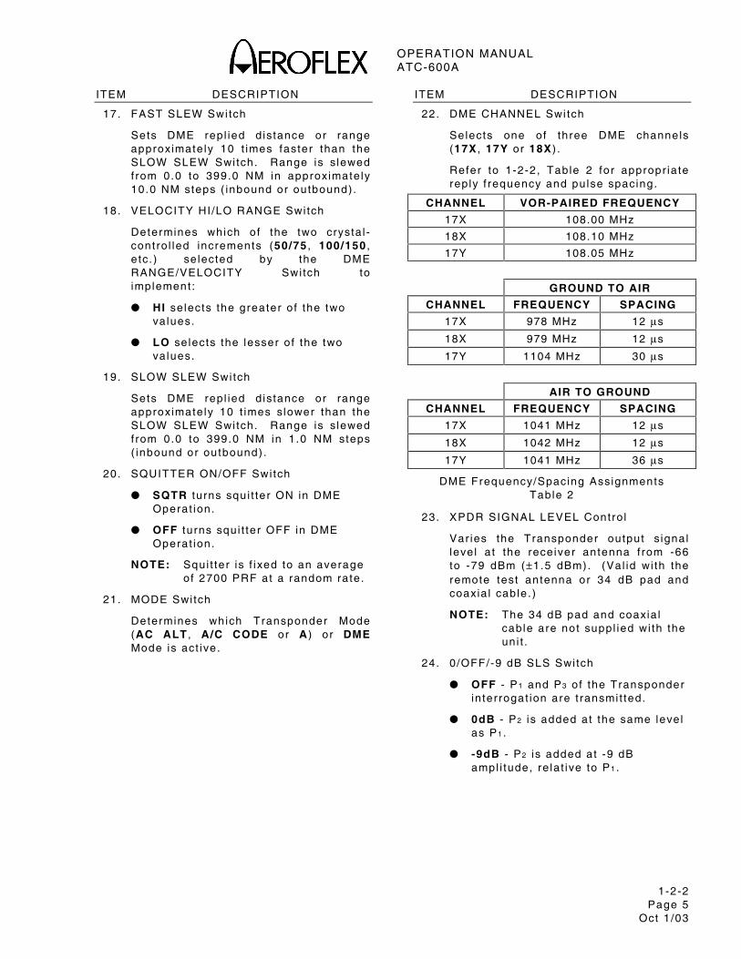
22. DME CHANNEL Swi tch
Selects one of three DME channels (17X , 17Y or 18X ) .
Refer to 1-2-2, Table 2 for appropr ia te rep ly f requency and pulse spacing.
CHANNEL VOR-PAIRED FREQUENCY
17X 108.00 MHz
18X 108.10 MHz
17Y 108.05 MHz
GROUND TO AIR
CHANNEL FREQUENCY SPACING
17X 978 MHz 12 µs
18X 979 MHz 12 µs
17Y 1104 MHz 30 µs
AIR TO GROUND
CHANNEL FREQUENCY SPACING
17X 1041 MHz 12 µs
18X 1042 MHz 12 µs
17Y 1041 MHz 36 µs
DME Frequency/Spacing Assignments Table 2
23. XPDR SIGNAL LEVEL Contro l
Var ies the Transponder output s ignal leve l a t the receiver antenna f rom -66 to -79 dBm (±1.5 dBm). (Val id wi th the remote test antenna or 34 dB pad and coaxia l cable. )
NOTE: The 34 dB pad and coaxia l cable are not suppl ied wi th the uni t .
24. 0 /OFF/-9 dB SLS Swi tch
OFF - P1 and P3 of the Transponder in ter rogat ion are t ransmi t ted.
0dB - P2 is added at the same leve l as P1 .
-9dB - P2 is added at -9 dB ampl i tude, re la t ive to P1 .
OPERATION MANUAL ATC-600A
1-2-2 Page 6
Oct 1 /03
ITEM DESCRIPTION
25. FRAMING PULSE SPACING Contro l
Used to ca lcu la te the posi t ion and width of the the F2 pu lse by rotat ing cw or ccw unt i l the F2 PULSE SPACING Indicator is l i t ( ind icat ing the exact leading and t ra i l ing edges of the F2 pu lse) .
NOTE: The approximate width of the F2 pu lse equals the d i f ference between the lowest and h ighest FRAMING PULSE SPACING Contro l set t ings at which the F2 PULSE SPACING Indicator is l i t .
26. ALTITUDE ENCODER INPUT Connector
Used for d i rect connect ion of a l t imeter output for encoding a l t imeter test ing. (MODE Swi tch must be set to A/C ALT for a l t imeter test ing and input pu lse must be per ARINC 532D [Appendix C] . )
NOTE: ALTITUDE ENCODER INPUT Connector P in-Out is shown in Appendix A.
27. INTERROGATION SPACING Contro l
Used to ad just the in ter rogat ion spacing f rom P1 to P2 and P3 in Transponder operat ion.
P1 and P3 in ter rogat ion spacing is set a t 8 and 21 µs. P2 in ter rogat ion spacing is 2 µs.
The INTERROGATION SPACING Contro l moves P2 and P3 ±1.0 µs re la t ive to P1 . P2 and P3 spacing remains constant . (Refer to 1-2-2, F igure 4. )
ITEM DESCRIPTION
28. PWR/BAT Swi tch
Two posi t ion swi tch contro ls power to the Test Set :
PWR connects Test Set to ac l ine power connected to AC IN Connector .
BAT connects or d isconnects Test Set f rom in ternal Bat tery. Connect ing the Test Set to the Bat tery act ivates an in ternal bat tery t imer . Test Set operat ion d isconnects f rom the in ternal Bat tery af ter reaching the in ternal bat tery t imer l imi t (≈6 to 10 min) or by pressing the PWR/BAT Swi tch to BAT to d isconnect .
29. PWR Indicator
Is l i t when apply ing ac or bat tery power to the Test Set .
30. BAT TEST Swi tch
When pressed, ind icates bat tery vo l tage on XPDR % RPLY/DME PRF Meter . (Lef t edge of whi te band ind icates 12.1 V.)
31. SYS/LAMP TEST Swi tch
LAMP - a l l OCTAL READOUT Indicators are l i t .
SYS - F2 PULSE SPACING Indicator and the BINARY READOUT Indicators (C4 and D2) are l i t ; in ternal c i rcu i ts are checked in Transponder Modes:
AC ALT - NUMERICAL Readout d isp lays 126.7 thousand feet .
A/C CODE - NUMERICAL Readout d isp lays 0042.
NOTE: Center posi t ion is OFF.
OPERATION MANUAL ATC-600A
1-2-2 Page 7
Oct 1 /03
2.2 REAR PANEL
Refer to 1-2-2, F igure 2.
ITEM DESCRIPTION
32. DIODE SWITCH INPUT Connector
Used wi th an h igh impedance probe to moni tor a l l modulator pu lses sent to the in ternal d iode swi tch.
33. DETECTED RF VIDEO OUTPUT Connector
Used wi th an h igh impedance probe to moni tor detected RF Video f rom the UUT.
34. SYNC OUTPUT Connector
Used wi th an h igh impedance probe to moni tor the posi t ive go ing TTL leve l pu lse (present dur ing Transponder operat ion) .
NOTE: Pulse should be co incident wi th the leading edge of P1 of the Transponder in ter rogat ion.
Used, wi th a coaxia l cable connected to an external Osci l loscope Sync/Tr igger Connector , for v iewing XPDR Inter rogat ion and/or Reply Pulses.
NOTE: The coaxia l cable is not suppl ied wi th the uni t .
35. FUSES
Fuses input power to the Test Set . Refer to Table 1-2-1, Table 1 for correct fuse size and type.
36. VOLTAGE SELECT Swi tch
Selects 115 or 230 VAC to match input ac power.
37. AC POWER Connector
Provides input for external ac power. Refer to para 1-2-1.5 for Power Requi rements.
OPERATION MANUAL ATC-600A
1-2-2 Page 8
Oct 1 /03
F1
C1
A1
C2
2A
4C
4A
XB
1D
1B
22
D4
B4
D2
FS
P 1
TR
AN
SP
ON
DE
R R
EP
LY P
ULS
E A
SS
IGN
ME
NT
ALT
ITU
DE
TR
AN
SM
ISS
ION
CO
DE
2000
2500
500
1000
1500
-500
0
-1000
6500
6000
5500
5000
4500
3500
3000
4000
12500
12000
11500
10000
11000
10500
9500
9000
8000
8500
7500
7000
17000
16000
15500
15000
14500
14000
13500
13000
18000
19000
ALT
ITU
DE
IN F
EE
T
A A A
1 2 4
B B421
B
2C
4CC
1
500
FO
OT
GR
AY
CO
DE
FR
OM
AB
OV
E
100
FO
OT
INC
RE
ME
NT
ALT
ITU
DE
IN T
HO
US
AN
DS
OF
FE
ET
100
FO
OT
INC
RE
ME
NT
TA
BLE
100
FO
OT
PU
LSE
SS
UM
OF
DIG
ITS
OF
GR
AY
CO
DE
C1
2C
4C
OD
DE
VE
N
0 0 0 1 1
0 1 1 1 0
1 1 0 0 0
7 6 5 4 3
8 9 0 1 2
RE
PLY
PU
LSE
AS
SIG
NM
EN
T
500
CO
DE
INC
RE
ME
NT
GR
AY
CO
DE
FO
R 1
00 F
OO
T IN
CR
EM
EN
TS
EE
BE
LOW
1 1CBB
2 4
D2
A BA42
AD
14 4
C C2
* 0
OR
1 IN
A P
ULS
E P
OS
ITIO
N IN
DIC
AT
ES
TH
EA
BS
EN
CE
FO
R P
RE
SE
NC
E O
F A
PU
LSE
RE
SP
EC
TIV
ELY
.
0000
0001
0011
0010
0110
0111
0101
0100
1100
1101
1111
1110
1010
1011
1001
1000
0 31 32 63 64 95 96 127
128
159
160
191
192
223
224
255
1 30 33 62 65 94 97 126
129
158
161
190
193
222
225
254
2 29 34 61 66 93 98 125
130
157
162
189
194
221
226
253
3 28 35 60 67 92 99 124
131
156
163
188
195
220
227
252
4 27 36 59 68 91 100
123
132
155
164
187
196
119
228
251
5 26 37 58 69 90 101
122
133
154
165
186
197
218
229
250
6 25 38 57 70 89 102
121
134
153
166
185
198
217
230
249
7 24 39 56 71 88 103
120
135
152
167
184
199
216
231
248
8 23 40 55 72 87 104
119
136
151
168
183
200
215
232
247
9 22 41 54 73 86 105
118
137
150
169
182
201
214
233
246
10 21 42 53 74 85 106
117
138
149
170
181
202
213
234
245
11 20 43 52 75 84 107
116
139
148
171
180
203
212
235
244
12 19 44 51 76 83 108
115
140
147
172
179
204
211
236
243
13 18 45 50 77 82 109
114
141
146
173
178
205
210
237
242
14 17 46 49 78 81 110
113
142
145
174
177
206
209
238
241
15 16 47 48 79 80 111
112
143
144
175
176
207
208
239
240
0000
0001
0011
0010
0110
0111
0101
0100
1100
1101
1111
1110
1010
1011
1001
1000
UN
IT D
IST
AN
CE
RE
FLE
CT
ED
DIN
AR
Y C
OD
E F
OR
8 B
ITS
256
INC
RE
ME
NT
S (
500
FO
OT
EA
CH
)G
IVIN
G A
LTIT
UD
E F
RO
M -
1000
FE
ET
TO
127
,000
FE
ET
.D
,D
,A
,A
P
ULS
ES
A
,B
,B
,B
PU
LSE
S*
41
24
24
12
-10
4
9
14
19
24
29
34
39
44
49
54
59
64
69
94
89
84
79
74
99
104
109
114
119
124
0080
7006
ALT
ITU
DE
CO
DE
FO
R M
OD
E C
RE
PO
RT
ING
CO
DE
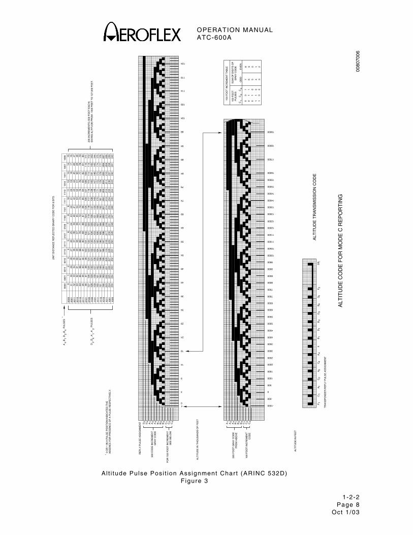
A l t i tude Pulse Posi t ion Assignment Char t (ARINC 532D) F igure 3
OPERATION MANUAL ATC-600A
1-2-3 Page 1
Oct 1 /03
3. GENERAL OPERATING PROCEDURES
3.1 GENERAL
The ATC-600A is a bench and ramp test inst rument for Transponder and DME Test Systems.
This sect ion conta ins operat ing inst ruct ions for the ATC-600A. The operat ing inst ruct ions conta in genera l procedures, ident i fy ing the contro ls, connectors, ind icators used for the ind iv idual test funct ions. For speci f ic Uni t Under Test (UUT) Procedures, re fer to the appropr ia te UUT Manual .
CAUTION: WHEN OPERATING THE TEST SET IN A VERTICAL POSITION, REMOVE THE LID TO PREVENT THE TEST SET FROM TIPPING OVER.
Refer to 1-2-2, F igure 2 for locat ion of contro ls, connectors and ind icators.
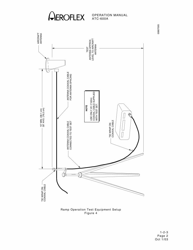
3.2 RAMP OPERATION EQUIPMENT
Ramp test ing requi res the use of a remote test antenna and t r ipod.
3.3 BENCH OPERATION EQUIPMENT
Bench test ing requi res the use of a 34 dB pad and d i rect coaxia l cable connect ions between the Test Set and UUT.
NOTE: The 34 dB pad and coaxia l cable are not suppl ied wi th the uni t .
3.4 BATTERY PARAMETERS
The bat tery permi ts complete ly por tab le ramp operat ion for up to two hours.
In bat tery operat ion, an automat ic t imer turns the Test Set OFF af ter 7 to 10 minutes. The Test Set can be recycled by pressing the PWR/BAT Swi tch to the BAT posi t ion.
When the BAT Test Swi tch is pressed, the XPDR % RPLY/DME PRF MTR disp lays the bat tery vo l tage. Normal bat tery charged condi t ion is ind icated as wel l wi th in the whi te band. The le f t edge of the whi te band ind icates 12.1 V) . An automat ic low vo l tage cutof f c i rcu i t turns the Test Set OFF when the bat tery vo l tage drops under 11.7 V.
NOTE: I f the Test Set is used only for bench operat ion, the bat tery can lose storage abi l i ty . The Test Set should be operated per iod ica l ly on bat tery power to a l low the bat tery to par t ia l ly d ischarge.
OPERATION MANUAL ATC-600A
1-2-3 Page 2
Oct 1 /03
0080
7005
TIE
WR
AP
ON
CO
AX
IAL
CA
BLE
30"
AV
G. (
76.2
cm
)15
" M
IN. (
38.1
cm
)
AN
TE
NN
A C
OA
XIA
L C
AB
LEF
OR
AN
TE
NN
A S
PA
CIN
G
AIR
CR
AF
TA
NT
EN
NA
TE
ST
AN
TE
NN
A A
PP
RO
X.
LEV
EL
TO
AIR
CR
AF
TA
NT
EN
NA
AN
TE
NN
A C
OA
XIA
L C
AB
LEC
ON
NE
CT
ED
TO
TE
ST
SE
T
TIE
WR
AP
ON
CO
AX
IAL
CA
BLE
US
E O
NLY
25’
(7.
62m
)C
OA
XIA
L C
AB
LE S
UP
PLI
ED
WIT
H T
ES
T S
ET
.
NO
TE
Ramp Operat ion Test Equipment Setup F igure 4
OPERATION MANUAL ATC-600A
1-2-3 Page 3
Oct 1 /03
3.5 TRANSPONDER OPERATION TEST EQUIPMENT SET UP
Refer to 1-2-2, F igure 4.
STEP PROCEDURE
1. Set up the remote test antenna on the t r ipod. Adjust test antenna height to be equal to a i rcraf t Transponder antenna. (Test antenna is usual ly posi t ioned for convenience,)
2 . Hor izonta l ly posi t ion test antenna the d istance f rom a i rcraf t antenna ind icated on test antenna’s coaxia l cable, approximate ly 21 inches (53.34 cm).
3 . Route loose end of coaxia l cable in to the a i rcraf t v ia a vent window, door or o ther opening.
CAUTION: DAMAGE TO THE TEST SET COULD RESULT WHEN THE REMOTE TEST ANTENNA IS POSITIONED CLOSER THAN 15 INCHES (38.1 CM) TO THE AIRCRAFT ANTENNA WHEN THE TEST SET IS ON.
3.6 TRANSPONDER OPERATION TESTS
3.6.1 Pi lot ’s Code
STEP PROCEDURE
1. Press PWR/BAT Swi tch to BAT .
2 . Connect remote test antenna coaxia l cable to RF INPUT/OUTPUT Connector .
3 . Set MODE Swi tch to A/C CODE .
4 . Power-up a i rcraf t Transponder ; le t run in “standby” for severa l minutes. Set Transponder Contro l Head to A/C Mode. Set p i lo t ’s code in to Contro l Head.
5. Ver i fy NUMERICAL Readout d isp lays p i lo t ’s code.
6. Ver i fy appropr ia te OCTAL READOUT Indicators are l i t .
OPERATION MANUAL ATC-600A
1-2-3 Page 4
Oct 1 /03
3.6.2 Alt i tude Code
STEP PROCEDURE
1. Set MODE Swi tch to A/C ALT .
2 . Ver i fy NUMERICAL Readout d isp lays output o f encoding a l t imeter in thousands of feet (wi th Baro Knob on encoding a l t imeter set to 29.92 inches [76.0 cm] Hg) .
3 . Ver i fy appropr ia te OCTAL READOUT Indicators are l i t .
NOTE: The encoding a l t imeter code output is unaf fected by changing the Baro Knob set t ing and a lways ind icates a l t i tude referenced to 29.92 inches (76.0 cm) Hg.
3.6.3 Peak Transponder Power
STEP PROCEDURE
1. Set MODE Swi tch to A/C ALT, ALT CODE or A .
2 . Set FREQ/PWR Swi tch to PWR .
3 . Ver i fy FREQ/PWR Meter d isp lays the Transponder ’s peak t ransmi t t ing power.
OPERATION MANUAL ATC-600A
1-2-3 Page 5
Oct 1 /03
3.6.4 Transponder Frequency
STEP PROCEDURE
1. Set FREQ/PWR Swi tch to PWR .
2 . Set P i lo t ’s Code of 0000 in to Transponder Contro l Head and remove a l l a t i tude code pulses.
3 . Adjust FREQ GAIN Contro l for a mid-scale FREQ/PWR Meter ind icat ion.
4 . Rotate XMTR FREQ Contro l for a peak FREQ/PWR Meter ind icat ion.
5 . At the peak ind icat ion, read deviat ion ( in MHz) ( f rom 1090 MHz) d i rect ly f rom XMTR FREQ Contro l .
3.6.5 Percent Reply
STEP PROCEDURE
NOTE: The XPDR % RPLY/DME PRF Meter d isp lays the percent rep ly of the Transponder to in ter rogat ions f rom the Test Set .
NOTE: The XPDR % RPLY/DME PRF Meter should d isp lay 100% for normal operat ing condi t ions.
OPERATION MANUAL ATC-600A
1-2-3 Page 6
Oct 1 /03
3.6.6 SLS Operat ion
STEP PROCEDURE
1. Set MODE Swi tch to A/C ALT or A/C CODE .
2 . Using XPDR SIGNAL LEVEL Contro l , set RF leve l output to 3 dB above min imum t r igger leve l (MTL).
CAUTION: DAMAGE TO THE TEST SET COULD RESULT WHEN THE REMOTE TEST ANTENNA IS POSITIONED CLOSER THAN 15 INCHES (38.1 CM) TO THE AIRCRAFT ANTENNA WHEN THE TEST SET IS ON.
3. Set 0/OFF/-9 dB SLS Swi tch to 0dB .
4 . Ver i fy Transponder mainta ins ≤3% reply on XPDR % RPLY/DME PRF Meter .
5 . Set 0/OFF/-9 dB SLS Swi tch to -9dB .
6 . Ver i fy Transponder mainta ins >90% reply on XPDR % RPLY/DME PRF Meter .
3.6.7 IDENT (XPDR) Pulse Output
STEP PROCEDURE
1. Press Ident But ton on the Transponder Contro l Head.
2. Ver i fy IDENT PULSE Indicator is l i t . ( IDENT PULSE Ind icator stays l i t for durat ion of IDENT pulse for approximate ly 30 seconds.)
NOTE: When the Test Set is in A/C ALT Mode, the Ident Pulse is pa i red wi th the D4 pu lse.
OPERATION MANUAL ATC-600A
1-2-3 Page 7
Oct 1 /03
3.6.8 Inval id ALT Indicator
STEP PROCEDURE
NOTE: When l i t , ind icates a received a l t i tude code has an unassigned combinat ion of codes.
NOTE: The condi t ions to VALID Al t i tude in format ion are the presence of a t least one of the C Pulses (C1, C2 or C4) and never C1 and C4 ON at the same t ime.
3.6.9 XPDR Receiver-Decoder Limits
STEP PROCEDURE
1. Adjust INTERROGATION SPACING Contro l le f t o f 0 unt i l the XPDR % RPLY/DME PRF Meter fa l ls to 0. (Transponder decoder input l imi ts are exceeded.) Note reading.
2. Adjust INTERROGATION SPACING Contro l r ight o f 0 unt i l the XPDR % RPLY/DME PRF Meter fa l ls to 0. (Transponder decoder input l imi ts are exceeded.) Note reading.
NOTE: The INTERROGATION SPACING Contro l is normal ly set to 0.
NOTE: Transponder Decoder l imi ts should be symetr ica l above the “0” set t ing on the INTERROGATION SPACING Contro l .
OPERATION MANUAL ATC-600A
1-2-3 Page 8
Oct 1 /03
3.6.10 Transponder Pulse Spacing
STEP PROCEDURE
NOTE: I f the F2 PULSE SPACING Indicator is l i t , the F2 pu lse of the rep ly is e i ther missing or is improper ly spaced.
1. Adjust FRAMING PULSE SPACING Contro l le f t o f zero unt i l the F2 PULSE SPACING Indicator is l i t . Note posi t ion of FRAMING PULSE SPACING Contro l .
2 . Adjust FRAMING PULSE SPACING Contro l r ight o f zero unt i l the F2 PULSE SPACING Indicator is l i t . Note posi t ion of FRAMING PULSE SPACING Contro l .
3 . Calcu late d i f ference between posi t ion in Step 1 and posi t ion in Step 2 - th is is the approximate width of the F2 pu lse.
NOTE: I f the F2 pu lse is d isp laced, the other rep ly pu lses may be skewed out o f posi t ion propor t ional ly.
NOTE: Transponder Decoder l imi ts should be symetr ica l above the “0” set t ing on the INTERROGATION SPACING Contro l .
3.6.11 Receiver Sensit iv i ty
STEP PROCEDURE
1. Set MODE Swi tch to A/C CODE .
2 . Adjust XPDR SIG LEVEL Contro l fu l ly ccw.
3. Ver i fy XPDR % RPLY/DME PRF Meter d isp lays 100% rep ly.
4 . Adjust XPDR SIG LEVEL Contro l cw unt i l XPDR % RPLY/DME PRF Meter d isp lays 90% rep ly.
5 . Note posi t ion on XPDR SIG LEVEL Contro l . (Th is is the min imum t r igger leve l [MTL] of Transponder in -dBm.)
6 . Ver i fy the MTL is -69 dBm to -77 dBm (±1.5 dBm) wi th a 34 dB pad. Record MTL.
7. Set MODE Swi tch to A/C ALT .
8 . Repeat Steps 2-6.
9 . Ver i fy rece iver sensi t iv i ty (d i f ference in MTL of the A/C CODE and A/C ALT ) is ≤1.0 dBm.
10. Adjust XPDR SIG LEVEL Contro l fu l ly ccw.
OPERATION MANUAL ATC-600A
1-2-3 Page 9
Oct 1 /03
3.7 DME OPERATION TEST EQUIPMENT SET UP
Refer to 1-2-2, F igure 4.
STEP PROCEDURE
1. Set up the remote test antenna on the t r ipod. Adjust test antenna height to be equal to a i rcraf t Transponder antenna. (Test antenna is usual ly posi t ioned for convenience,)
2 . Hor izonta l ly posi t ion test antenna the d istance f rom a i rcraf t antenna ind icated on test antenna’s coaxia l cable, approximate ly 21 inches (53.34 cm).
3 . Route loose end of coaxia l cable in to the a i rcraf t v ia a vent window, door or o ther opening.
CAUTION: DAMAGE TO THE TEST SET COULD RESULT WHEN THE REMOTE TEST ANTENNA IS POSITIONED CLOSER THAN 15 INCHES (38.1 CM) TO THE AIRCRAFT ANTENNA WHEN THE TEST SET IS ON.
3.8 DME OPERATION TESTS
3.8.1 DME Range or Distance Operat ion
STEP PROCEDURE
1. Press PWR/BAT Swi tch to BAT .
2 . Power-up a i rborne DME and a l low severa l minutes for warm-up.
3 . Set DME to Distance Disp lay Mode in desi red range scale.
4 . Set DME Frequency to 108.00 .
5 . Set MODE Swi tch to DME .
6 . Set DME RANGE/VELOCITY Swi tch to RANGE .
7 . Set DME CHANNEL Swi tch to 17X .
8 . Set SQUITTER ON/OFF Swi tch to SQTR .
9 . Set FAST SLEW Swi tch and SLOW SLEW Swi tch to IN then to OUT ( to obta in a desi red d istance in naut ica l mi les) .
10. Ver i fy DME locks on at the precise range programmed.
NOTE: Any number of d i f ferent d istances f rom 0 to 399 NM may be simi l iar ly checked in 1 NM increments.
OPERATION MANUAL ATC-600A
1-2-3 Page 10 Oct 1 /03
3.8.2 DME Velocity Operat ion
STEP PROCEDURE
1. Press PWR/BAT Swi tch to BAT .
2 . Power-up a i rborne DME and a l low severa l minutes for warm-up.
3 . Set DME to Distance Disp lay Mode in desi red range scale.
4 . Set DME Frequency to 108.00 .
5 . Set MODE Swi tch to DME .
6 . Set DME RANGE/VELOCITY Swi tch to desi red ve loci ty set t ing.
7. Set VELOCITY HI /LO RANGE Switch to HI (se lects upper va lue) or to LO (se lect lower va lue) .
8 . Set FAST SLEW Swi tch and SLOW SLEW Swi tch to IN then to OUT ( to set a desi red star t ing range) .
9 . Set VELOCITY IN/OUT Swi tch to IN then to OUT ( to t rack the d istance toward or away f rom the ground stat ion) .
10. Ver i fy DME locks on and d isp lays the correct range and ve loci ty.
NOTE: I f the DME is set to d isp lay d istance in naut ica l mi les (NM), the d istance should equal the instantaneous range ind icated on the Test Set NUMERICAL Readout in 0 .1 NM.
NOTE: Any number of ve loci t ies and instantaneous d istances may be simi l iar ly checked.
3.8.3 DME Transmitted PRF
STEP PROCEDURE
1. Lock DME to desi red range or ve loci ty.
2 . Set Test Set DME PRF Swi tch to 0-30 .
3 . Ver i fy XPDR % RPLY/DME PRF Meter ind icates Track PRF .
4 . Increase Test Set range by 50 Mi les.
5 . Set Test Set DME PRF Swi tch to 0-300 .
6 . Ver i fy XPDR % RPLY/DME PRF Meter ind icates Search PRF as DME searches for the new range or ve loci ty.
NOTE: DME “memory t ime” should ho ld the last d isp layed range for 8 to 10 seconds before un locking the the range and search ing for the new range.
OPERATION MANUAL ATC-600A
1-2-3 Page 11 Oct 1 /03
3.8.4 Transmitter Peak Power and Frequency
STEP PROCEDURE
1. Connect DME to Test Set .
2 . Set FREQ/PWR Swi tch to PWR .
3 . Ver i fy RF peak power is d isp layed on FREQ/PWR Meter in kW.
4. To check crysta l to lerance:
Set FREQ/PWR Swi tch to FREQ.
Adjust FREQ GAIN Contro l for mid-scale def lect ion on FREQ/PWR Meter .
Adjust XMTR FREQ Contro l for peak reading on FREQ/PWR Meter .
NOTE: The Plus (+) and minus ( - ) s igns on the XMTR FREQ Contro l are reversed in DME operat ion (posi t ive va lues are le f t o f zero and negat ive va lues are r ight o f zero) .
3.8.5 IDENT Tone
STEP PROCEDURE
1. Set IDENT/50% RPLY Swi tch to IDENT .
2 . Ver i fy 1350 Hz tone is heard through the audio system.
NOTE: Addi t ion of the IDENT Tone is a good check of memory t ime, as the IDENT Tone supersedes a l l range and squi t ter pu lses.
OPERATION MANUAL ATC-600A
1-2-3 Page 12 Oct 1 /03
3.8.6 Percent Reply
STEP PROCEDURE
1. Set IDENT/50% RPLY Swi tch to 50% RPLY .
2 . Ver i fy 50% of a l l rep l ies to the DME are deleted.
NOTE: Delet ing hal f o f a l l rep l ies to the DME checks the ab i l i ty o f the DME to lock-on or to t rack under poor s ignal condi t ions.
3.8.7 Squit ter Lock-Out
STEP PROCEDURE
1. Set SQUITTER ON/OFF Swi tch to OFF .
2 . S lew range to desi red posi t ion.
3 . Set DME to appropr ia te channel :
17X 18X 17Y
108.00 108.10 108.05
4. Ver i fy af ter DME memory t ime, the DME drops out wi thout search ing.
NOTE: Most DME Systems are equipped wi th a Squi t ter Lock-Out to prevent search ing unt i l the Squi t ter is rece ived.
5. Set SQUITTER ON/OFF Swi tch to SQTR .
6 . Ver i fy DME begins search ing.
OPERATION MANUAL ATC-600A
1-2-3 Page 13 Oct 1 /03
3.8.8 17Y Channel Operat ion
STEP PROCEDURE
1. Set A i rcraf t Frequency Contro l to 108.05.
2 . Set Test Set DME CHANNEL Swi tch to 17Y .
3 . Per form tests in para 1-2-3.8.1 through 1-2-3.8.7.
3.8.9 DME ILS Channel Operat ion
STEP PROCEDURE
1. Set A i rcraf t Frequency Contro l to 108.10.
2 . Set Test Set DME CHANNEL Swi tch to 18X .
3 . Per form tests in para 1-2-3.8.1 through 1-2-3.8.7.
NOTE: The nominal t ransmi t ter f requency contro l reading should be -1. The DME t ransmi t ter f requency should increment by 1 MHz when channeled f rom 108.00 to 108.10.
OPERATION MANUAL ATC-600A
1-2-3 Page 14 Oct 1 /03
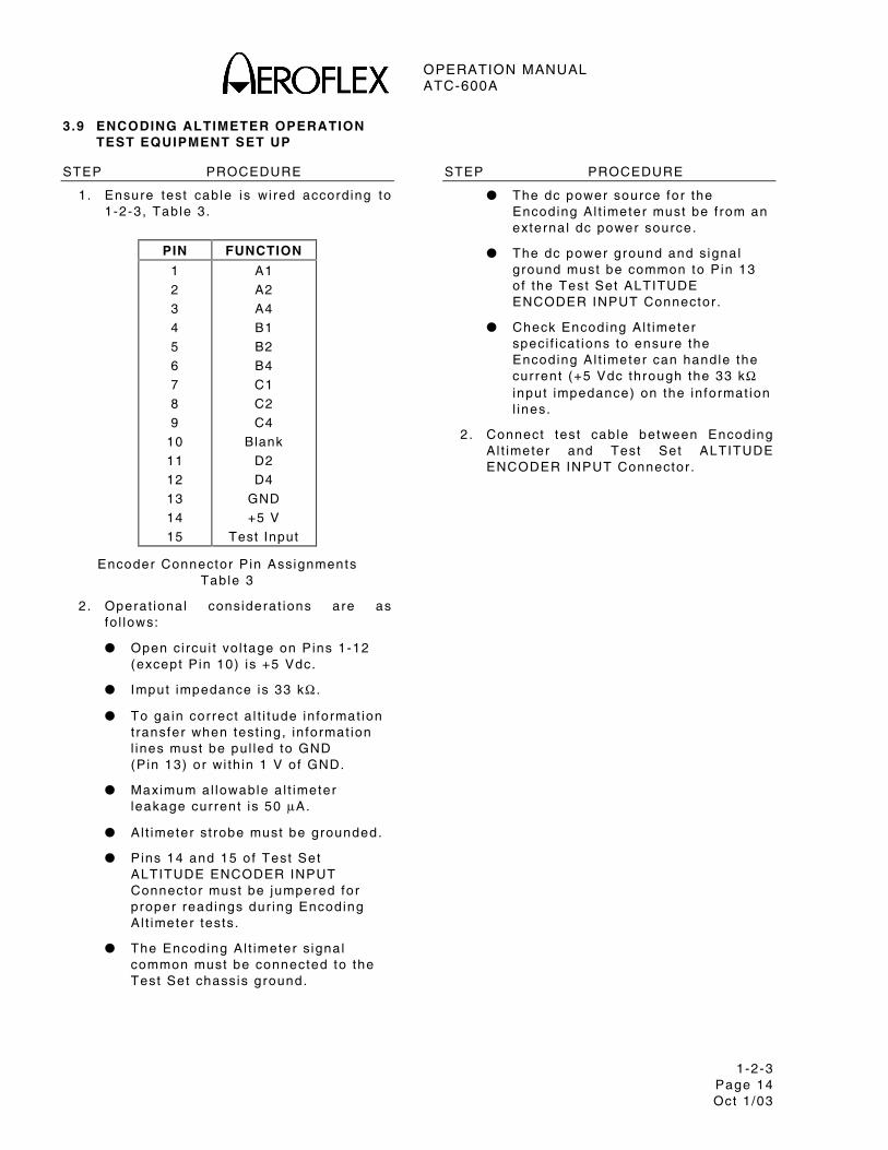
3.9 ENCODING ALTIMETER OPERATION TEST EQUIPMENT SET UP
STEP PROCEDURE
1. Ensure test cable is wi red accord ing to 1-2-3, Table 3.
PIN FUNCTION
1
2
3
4
5
6
7
8
9
10
11
12
13
14
15
A1
A2
A4
B1
B2
B4
C1
C2
C4
Blank
D2
D4
GND
+5 V
Test Input
Encoder Connector P in Assignments Table 3
2. Operat ional considerat ions are as fo l lows:
Open ci rcu i t vo l tage on Pins 1-12 (except P in 10) is +5 Vdc.
Imput impedance is 33 kΩ .
To gain correct a l t i tude in format ion t ransfer when test ing, in format ion l ines must be pul led to GND (Pin 13) or wi th in 1 V of GND.
Maximum al lowable a l t imeter leakage current is 50 µA.
Al t imeter st robe must be grounded.
Pins 14 and 15 of Test Set ALTITUDE ENCODER INPUT Connector must be jumpered for proper readings dur ing Encoding Al t imeter tests.
The Encoding Al t imeter s ignal common must be connected to the Test Set chassis ground.
STEP PROCEDURE
The dc power source for the Encoding Al t imeter must be f rom an external dc power source.
The dc power ground and signal ground must be common to Pin 13 of the Test Set ALTITUDE ENCODER INPUT Connector .
Check Encoding Al t imeter speci f icat ions to ensure the Encoding Al t imeter can handle the current (+5 Vdc through the 33 kΩ input impedance) on the in format ion l ines.
2 . Connect test cable between Encoding Al t imeter and Test Set ALTITUDE ENCODER INPUT Connector .
OPERATION MANUAL ATC-600A
1-2-3 Page 15 Oct 1 /03
3.10 ENCODING ALTIMETER TESTS
3.10.1 Alt i tude Display
STEP PROCEDURE
1. Ver i fy NUMERICAL Readout d isp lays a l t i tude in format ion f rom -1.0 to -126.7 thousand feet (1-2-2, F igure 3) .
2 . Ver i fy OCTAL READOUT Indicators d isp lay proper pu lse posi t ion.

OPERATION MANUAL ATC-600A
1-2-3 Page 16 Oct 1 /03
THIS PAGE INTENTIONALLY LEFT BLANK.
OPERATION MANUAL ATC-600A
1-3-1 Page 1
Oct 1 /03
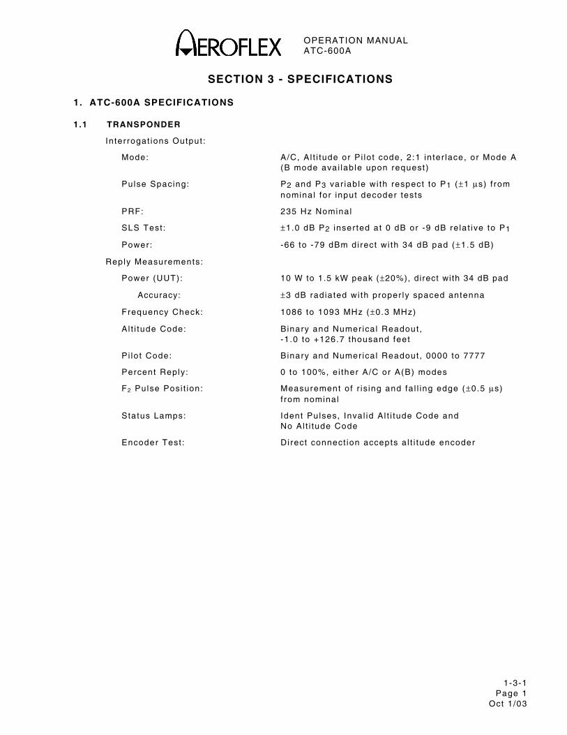
SECTION 3 - SPECIFICATIONS
1. ATC-600A SPECIFICATIONS
1.1 TRANSPONDER
In ter rogat ions Output :
Mode: A/C, A l t i tude or P i lo t code, 2 :1 in ter lace, or Mode A (B mode avai lab le upon request )
Pulse Spacing: P2 and P3 var iab le wi th respect to P1 (±1 µs) f rom nominal for input decoder tests
PRF: 235 Hz Nominal
SLS Test : ±1.0 dB P2 inser ted at 0 dB or -9 dB re la t ive to P1
Power: -66 to -79 dBm di rect wi th 34 dB pad (±1.5 dB)
Reply Measurements:
Power (UUT): 10 W to 1.5 kW peak (±20%), direct wi th 34 dB pad
Accuracy: ±3 dB radiated wi th proper ly spaced antenna
Frequency Check: 1086 to 1093 MHz (±0.3 MHz)
A l t i tude Code: B inary and Numer ica l Readout , -1 .0 to +126.7 thousand feet
P i lo t Code: B inary and Numer ica l Readout , 0000 to 7777
Percent Reply: 0 to 100%, e i ther A/C or A(B) modes
F2 Pulse Posi t ion: Measurement o f r is ing and fa l l ing edge (±0.5 µs) f rom nominal
Status Lamps: Ident Pulses, Inva l id A l t i tude Code and No Al t i tude Code
Encoder Test : Di rect connect ion accepts a l t i tude encoder
OPERATION MANUAL ATC-600A
1-3-1 Page 2
Oct 1 /03
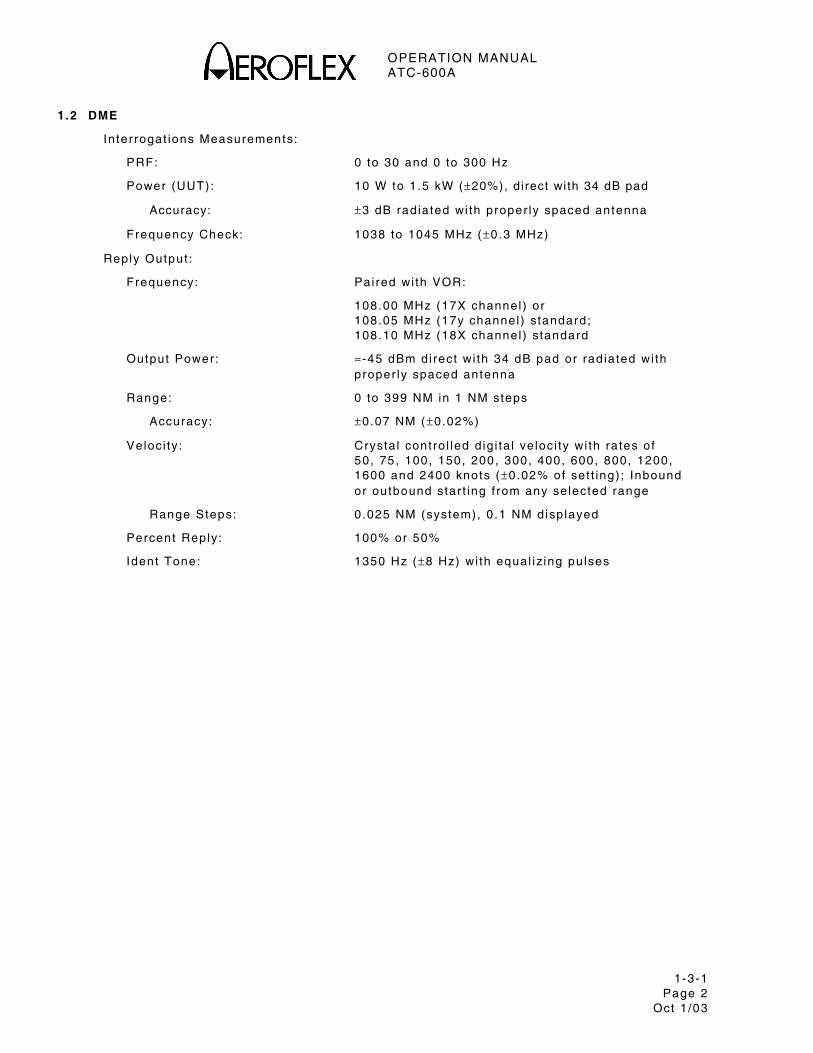
1.2 DME
In ter rogat ions Measurements:
PRF: 0 to 30 and 0 to 300 Hz
Power (UUT): 10 W to 1.5 kW (±20%), direct wi th 34 dB pad
Accuracy: ±3 dB radiated wi th proper ly spaced antenna
Frequency Check: 1038 to 1045 MHz (±0.3 MHz)
Reply Output :
Frequency: Pai red wi th VOR:
108.00 MHz (17X channel ) or 108.05 MHz (17y channel ) standard; 108.10 MHz (18X channel ) standard
Output Power: ≈ -45 dBm di rect wi th 34 dB pad or rad iated wi th proper ly spaced antenna
Range: 0 to 399 NM in 1 NM steps
Accuracy: ±0.07 NM (±0.02%)
Veloci ty: Crysta l contro l led d ig i ta l ve loci ty wi th ra tes of 50, 75, 100, 150, 200, 300, 400, 600, 800, 1200, 1600 and 2400 knots (±0.02% of set t ing) ; Inbound or outbound star t ing f rom any se lected range
Range Steps: 0 .025 NM (system), 0 .1 NM disp layed
Percent Reply: 100% or 50%
Ident Tone: 1350 Hz (±8 Hz) wi th equal iz ing pulses
OPERATION MANUAL ATC-600A
1-3-1 Page 3
Oct 1 /03
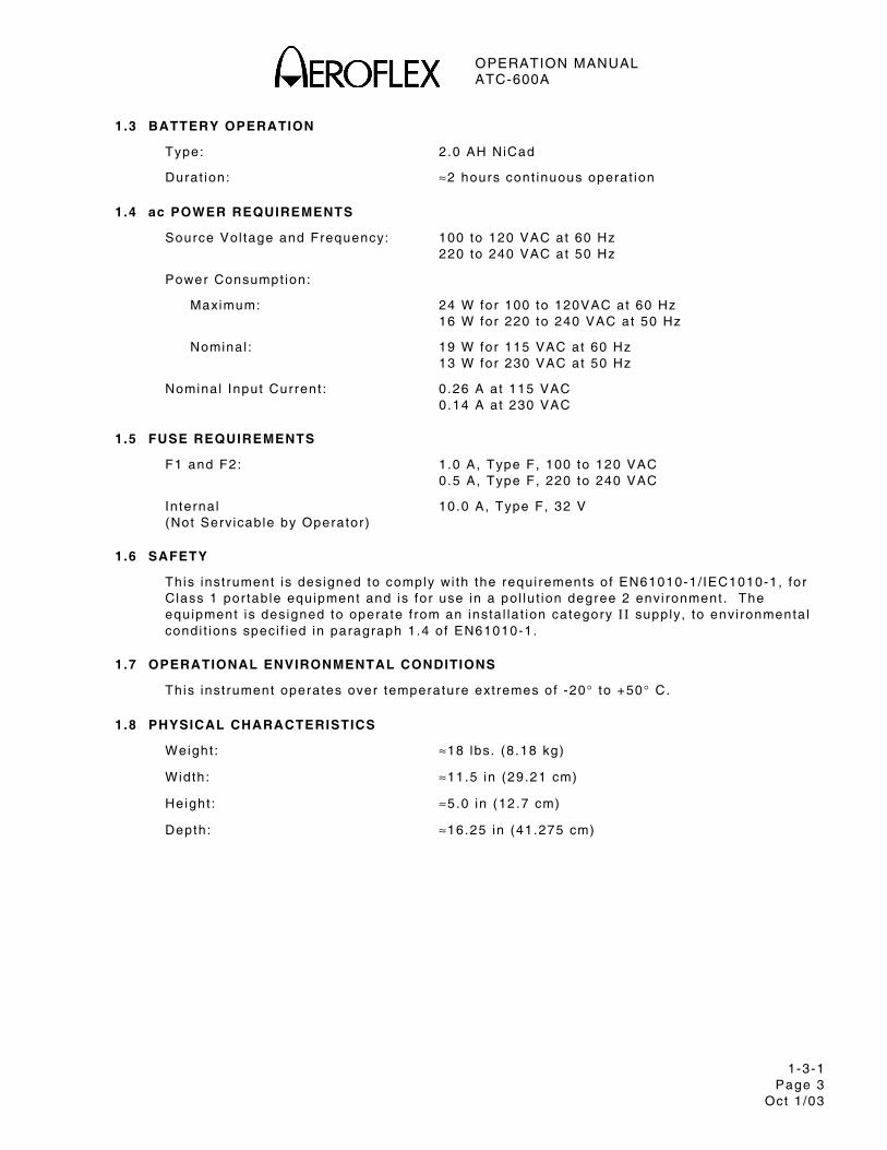
1.3 BATTERY OPERATION
Type: 2 .0 AH NiCad
Durat ion: ≈2 hours cont inuous operat ion
1.4 ac POWER REQUIREMENTS
Source Vol tage and Frequency: 100 to 120 VAC at 60 Hz 220 to 240 VAC at 50 Hz
Power Consumpt ion:
Maximum: 24 W for 100 to 120VAC at 60 Hz 16 W for 220 to 240 VAC at 50 Hz
Nominal : 19 W for 115 VAC at 60 Hz 13 W for 230 VAC at 50 Hz
Nominal Input Current : 0 .26 A at 115 VAC 0 .14 A at 230 VAC
1.5 FUSE REQUIREMENTS
F1 and F2: 1 .0 A, Type F, 100 to 120 VAC 0 .5 A, Type F, 220 to 240 VAC
Internal 10.0 A, Type F, 32 V (Not Servicable by Operator)
1.6 SAFETY
This inst rument is designed to comply wi th the requi rements of EN61010-1/ IEC1010-1, for Class 1 por tab le equipment and is for use in a po l lu t ion degree 2 envi ronment . The equipment is designed to operate f rom an insta l la t ion category I I supply, to envi ronmenta l condi t ions speci f ied in paragraph 1.4 of EN61010-1.
1.7 OPERATIONAL ENVIRONMENTAL CONDITIONS
This inst rument operates over temperature ext remes of -20° to +50° C.
1.8 PHYSICAL CHARACTERISTICS
Weight : ≈18 lbs. (8 .18 kg)
Width: ≈11.5 in (29.21 cm)
Height : ≈5.0 in (12.7 cm)
Depth: ≈16.25 in (41.275 cm)

OPERATION MANUAL ATC-600A
1-3-1 Page 4
Oct 1 /03
THIS PAGE INTENTIONALLY LEFT BLANK.
OPERATION MANUAL ATC-600A
1-4-1 Page 1
Oct 1 /03
SECTION 4 - SHIPPING
1. SHIPPING TEST SETS
1.1 INFORMATION
Test Sets returned to factory for ca l ibrat ion, service or repai r must be repackaged and sh ipped accord ing to the fo l lowing condi t ions:
Authorizat ion
Only return products to factory af ter f i rst rece iv ing author izat ion f rom Aerof lex Customer Service Depar tment .
CONTACT: Aerof lex Customer Service
Te lephone: (800) 835-2350 FAX: (316) 524-2623
Tagging Test Sets
Al l Test Sets must be tagged wi th :
Ident i f icat ion and address of owner
Nature of service or repai r requi red
Model Number
Ser ia l Number
Shipping Containers
Test Sets must be repackaged in or ig ina l sh ipp ing conta iners using Aerof lex packing molds. I f or ig ina l sh ipp ing conta iners and mater ia ls are unavai lab le, contact Aerof lex Customer Service for sh ipp ing inst ruct ions.
Freight Costs
Al l f re ight costs on non-warranty sh ipments are assumed by the customer. (See “Warranty Packet” for f re ight charge pol icy on warranty c la ims.)
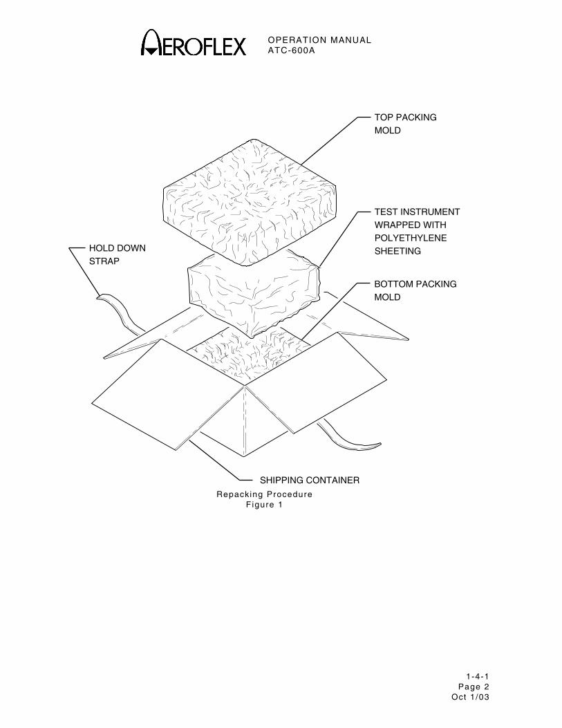
1.2 REPACKING PROCEDURE
Make sure bot tom packing mold is seated on f loor o f sh ipp ing conta iner .
Carefu l ly wrap Test Set wi th po lyethylene sheet ing to protect f in ish.
Place Test Set in to sh ipp ing conta iner , making sure Test Set is secure ly seated in bot tom packing mold.
Place top packing mold over top of Test Set and press down unt i l mold rests so l id ly in bot tom packing mold.
Close sh ipp ing conta iner l ids and seal wi th sh ipp ing tape or an indust r ia l stap ler . T ie a l l s ides of conta iner wi th break resistant rope, twine or equiva lent .
OPERATION MANUAL ATC-600A
1-4-1 Page 2
Oct 1 /03
TOP PACKINGMOLD
TEST INSTRUMENTWRAPPED WITHPOLYETHYLENESHEETING
BOTTOM PACKINGMOLD
SHIPPING CONTAINER
HOLD DOWNSTRAP
Repacking Procedure
F igure 1
OPERATION MANUAL ATC-600A
1-5-1 Page 1
Oct 1 /03
SECTION 5 - STORAGE
1. STORING TEST SETS
Perform the fo l lowing storage precaut ions whenever the Test Set is stored for extended per iods:
Disconnect Test Set f rom any e lect r ica l power source.
Disconnect and store ac power cable and other accessor ies wi th Test Set .
Cover Test Set to prevent dust and debr is f rom cover ing and enter ing Test Set .

OPERATION MANUAL ATC-600A
1-5-1 Page 2
Oct 1 /03
THIS PAGE INTENTIONALLY LEFT BLANK.
OPERATION MANUAL ATC-600A
APPENDIX A Page 1
Oct 1 /03
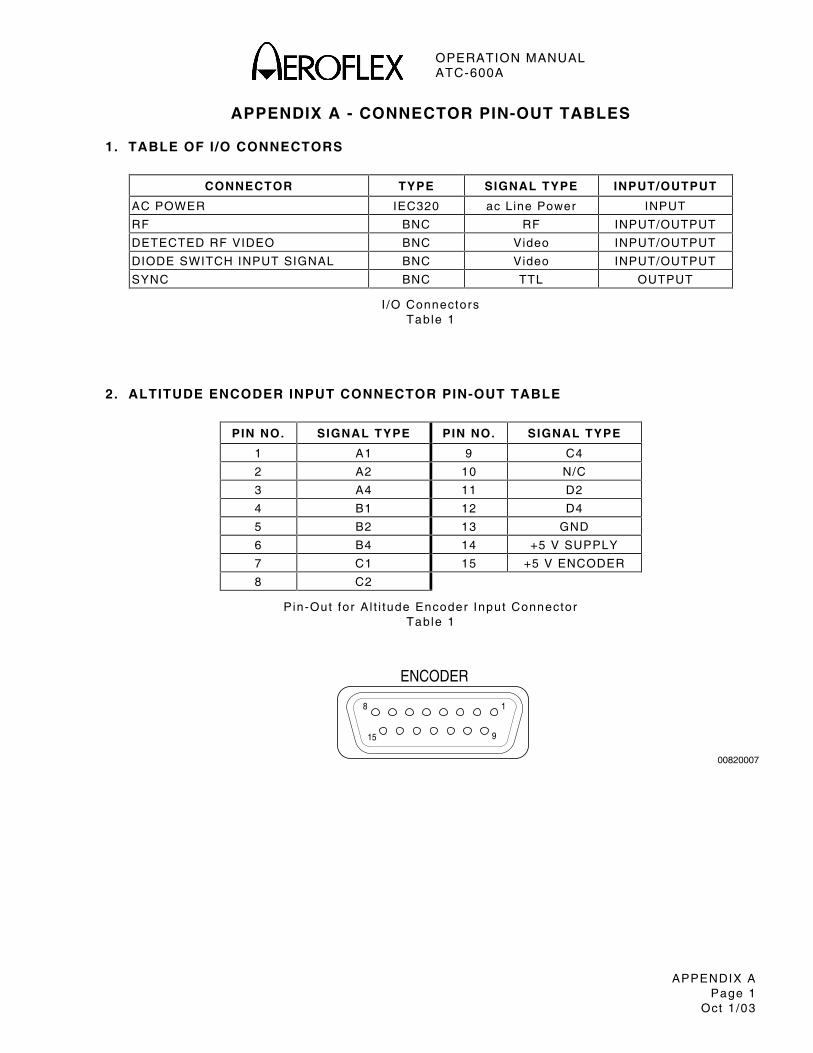
APPENDIX A - CONNECTOR PIN-OUT TABLES
1. TABLE OF I /O CONNECTORS
CONNECTOR TYPE SIGNAL TYPE INPUT/OUTPUT
AC POWER IEC320 ac Line Power INPUT
RF BNC RF INPUT/OUTPUT
DETECTED RF VIDEO BNC Video INPUT/OUTPUT
DIODE SWITCH INPUT SIGNAL BNC Video INPUT/OUTPUT
SYNC BNC TTL OUTPUT
I /O Connectors Table 1
2. ALTITUDE ENCODER INPUT CONNECTOR PIN-OUT TABLE
PIN NO. SIGNAL TYPE PIN NO. SIGNAL TYPE
1 A1 9 C4
2 A2 10 N/C
3 A4 11 D2
4 B1 12 D4
5 B2 13 GND
6 B4 14 +5 V SUPPLY
7 C1 15 +5 V ENCODER
8 C2
P in-Out for A l t i tude Encoder Input Connector Table 1
00820007
ENCODER
18
915

OPERATION MANUAL ATC-600A
APPENDIX A Page 2
Oct 1 /03
THIS PAGE INTENTIONALLY LEFT BLANK.
OPERATION MANUAL ATC-600A
APPENDIX B Page 1
Oct 1 /03
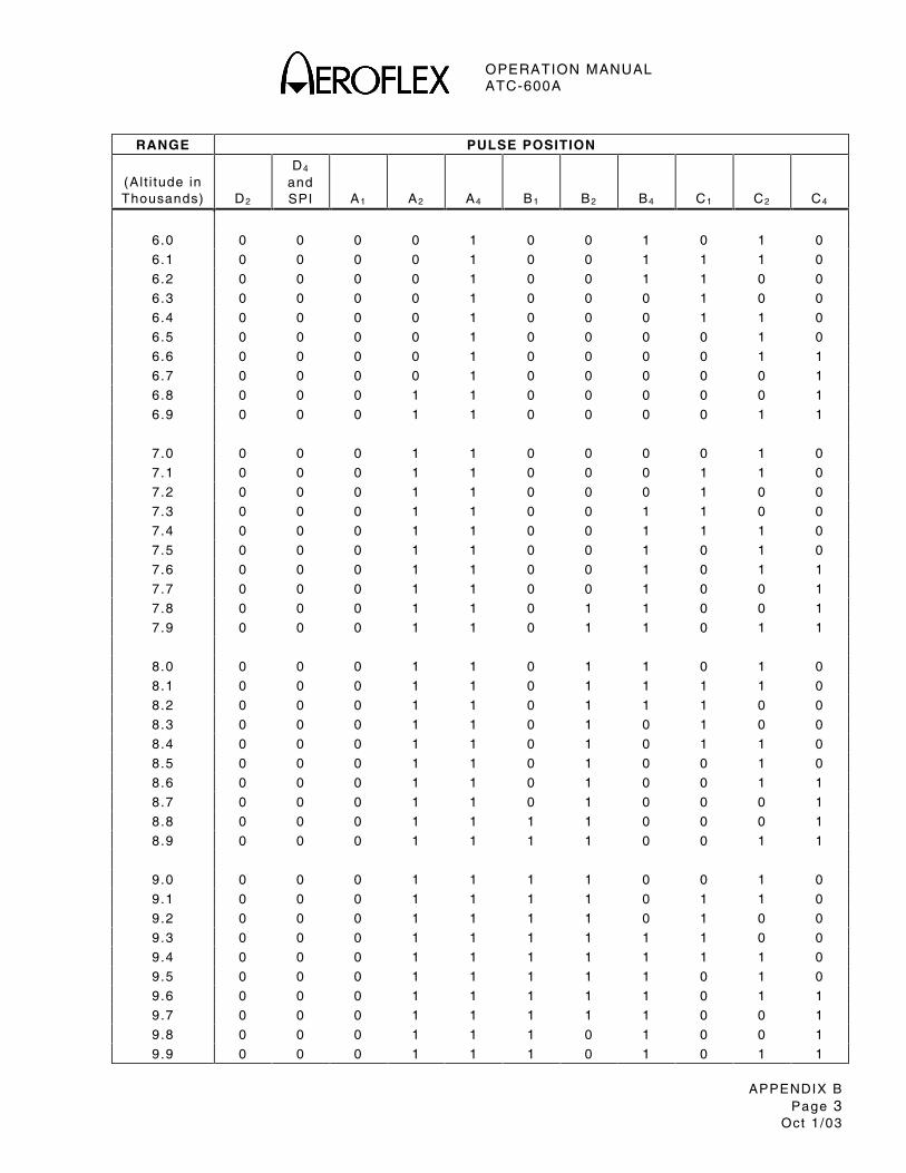
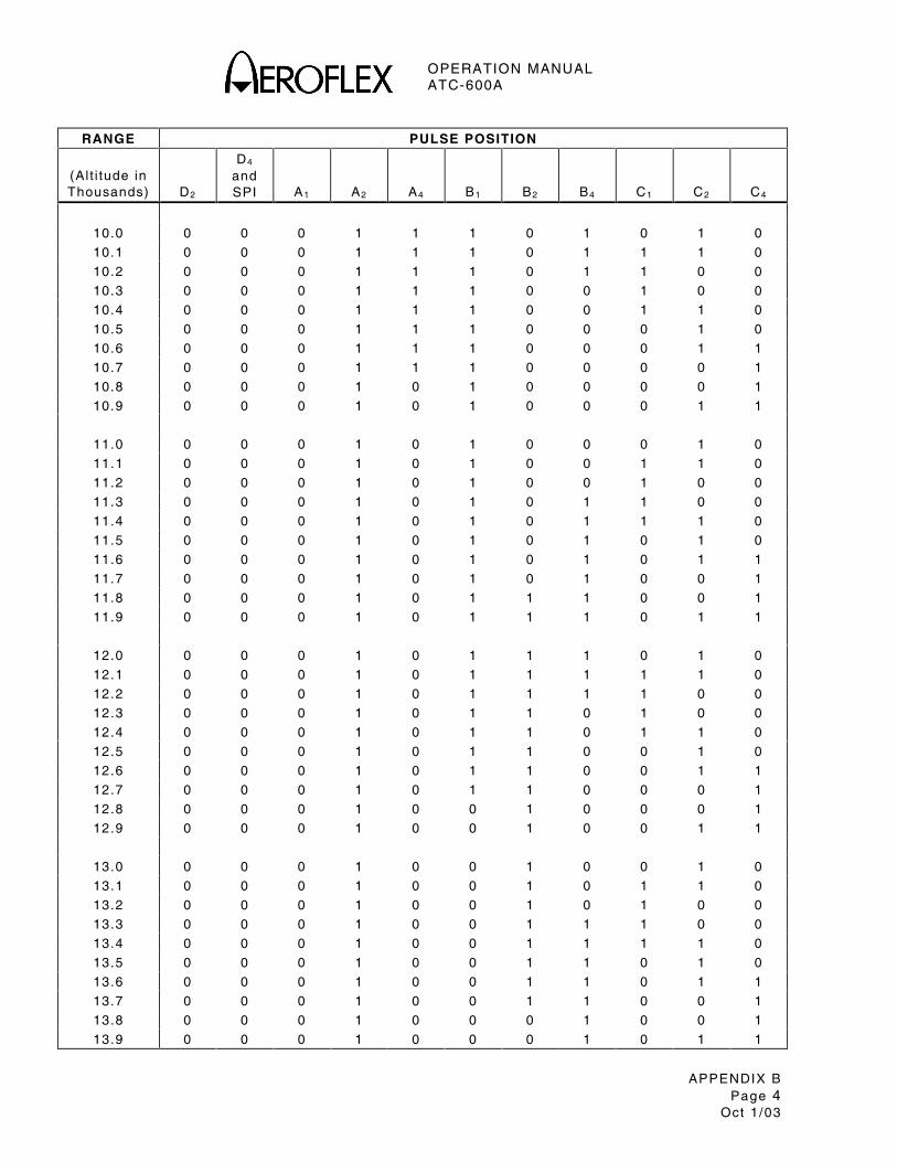
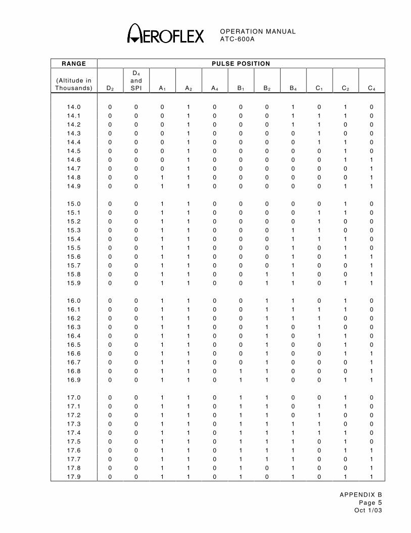
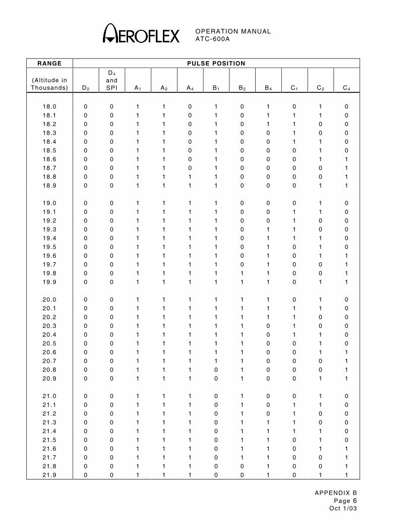
APPENDIX B - ALTITUDE TRANSMISSION CODE CHART
RANGE PULSE POSITION
(Al t i tude in Thousands)
D2
D4 and SPI
A1
A2
A4
B1
B2
B4
C1
C2
C4
-1.0 0 0 0 0 0 0 0 0 0 1 0
-0.9 0 0 0 0 0 0 0 0 1 1 0
-0.8 0 0 0 0 0 0 0 0 1 0 0
-0.7 0 0 0 0 0 0 0 1 1 0 0
-0.6 0 0 0 0 0 0 0 1 1 1 0
-0.5 0 0 0 0 0 0 0 1 0 1 0
-0.4 0 0 0 0 0 0 0 1 0 1 1
-0.3 0 0 0 0 0 0 0 1 0 0 1
-0.2 0 0 0 0 0 0 1 1 0 0 1
-0.1 0 0 0 0 0 0 1 1 0 1 1
0.0 0 0 0 0 0 0 1 1 0 1 0
0.1 0 0 0 0 0 0 1 1 1 1 0
0.2 0 0 0 0 0 0 1 1 1 0 0
0.3 0 0 0 0 0 0 1 0 1 0 0
0.4 0 0 0 0 0 0 1 0 1 1 0
0.5 0 0 0 0 0 0 1 0 0 1 0
0.6 0 0 0 0 0 0 1 0 0 1 1
0.7 0 0 0 0 0 0 1 0 0 0 1
0.8 0 0 0 0 0 1 1 0 0 0 1
0.9 0 0 0 0 0 1 1 0 0 1 1
1.0 0 0 0 0 0 1 1 0 0 1 0
1.1 0 0 0 0 0 1 1 0 1 1 0
1.2 0 0 0 0 0 1 1 0 1 0 0
1.3 0 0 0 0 0 1 1 1 1 0 0
1.4 0 0 0 0 0 1 1 1 1 1 0
1.5 0 0 0 0 0 1 1 1 0 1 0
1.6 0 0 0 0 0 1 1 1 0 1 1
1.7 0 0 0 0 0 1 1 1 0 0 1
1.8 0 0 0 0 0 1 0 1 0 0 1
1.9 0 0 0 0 0 1 0 1 0 1 1
2.0 0 0 0 0 0 1 0 1 0 1 0
2.1 0 0 0 0 0 1 0 1 1 1 0
2.2 0 0 0 0 0 1 0 1 1 0 0
2.3 0 0 0 0 0 1 0 0 1 0 0
2.4 0 0 0 0 0 1 0 0 1 1 0
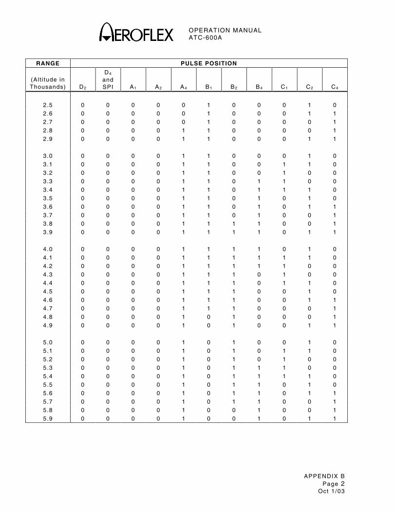
OPERATION MANUAL ATC-600A
APPENDIX B Page 2
Oct 1 /03
RANGE PULSE POSITION
(Al t i tude in Thousands)
D2
D4 and SPI
A1
A2
A4
B1
B2
B4
C1
C2
C4
2.5 0 0 0 0 0 1 0 0 0 1 0
2.6 0 0 0 0 0 1 0 0 0 1 1
2.7 0 0 0 0 0 1 0 0 0 0 1
2.8 0 0 0 0 1 1 0 0 0 0 1
2.9 0 0 0 0 1 1 0 0 0 1 1
3.0 0 0 0 0 1 1 0 0 0 1 0
3.1 0 0 0 0 1 1 0 0 1 1 0
3.2 0 0 0 0 1 1 0 0 1 0 0
3.3 0 0 0 0 1 1 0 1 1 0 0
3.4 0 0 0 0 1 1 0 1 1 1 0
3.5 0 0 0 0 1 1 0 1 0 1 0
3.6 0 0 0 0 1 1 0 1 0 1 1
3.7 0 0 0 0 1 1 0 1 0 0 1
3.8 0 0 0 0 1 1 1 1 0 0 1
3.9 0 0 0 0 1 1 1 1 0 1 1
4.0 0 0 0 0 1 1 1 1 0 1 0
4.1 0 0 0 0 1 1 1 1 1 1 0
4.2 0 0 0 0 1 1 1 1 1 0 0
4.3 0 0 0 0 1 1 1 0 1 0 0
4.4 0 0 0 0 1 1 1 0 1 1 0
4.5 0 0 0 0 1 1 1 0 0 1 0
4.6 0 0 0 0 1 1 1 0 0 1 1
4.7 0 0 0 0 1 1 1 0 0 0 1
4.8 0 0 0 0 1 0 1 0 0 0 1
4.9 0 0 0 0 1 0 1 0 0 1 1
5.0 0 0 0 0 1 0 1 0 0 1 0
5.1 0 0 0 0 1 0 1 0 1 1 0
5.2 0 0 0 0 1 0 1 0 1 0 0
5.3 0 0 0 0 1 0 1 1 1 0 0
5.4 0 0 0 0 1 0 1 1 1 1 0
5.5 0 0 0 0 1 0 1 1 0 1 0
5.6 0 0 0 0 1 0 1 1 0 1 1
5.7 0 0 0 0 1 0 1 1 0 0 1
5.8 0 0 0 0 1 0 0 1 0 0 1
5.9 0 0 0 0 1 0 0 1 0 1 1
OPERATION MANUAL ATC-600A
APPENDIX B Page 3
Oct 1 /03
RANGE PULSE POSITION
(Al t i tude in Thousands)
D2
D4 and SPI
A1
A2
A4
B1
B2
B4
C1
C2
C4
6.0 0 0 0 0 1 0 0 1 0 1 0
6.1 0 0 0 0 1 0 0 1 1 1 0
6.2 0 0 0 0 1 0 0 1 1 0 0
6.3 0 0 0 0 1 0 0 0 1 0 0
6.4 0 0 0 0 1 0 0 0 1 1 0
6.5 0 0 0 0 1 0 0 0 0 1 0
6.6 0 0 0 0 1 0 0 0 0 1 1
6.7 0 0 0 0 1 0 0 0 0 0 1
6.8 0 0 0 1 1 0 0 0 0 0 1
6.9 0 0 0 1 1 0 0 0 0 1 1
7.0 0 0 0 1 1 0 0 0 0 1 0
7.1 0 0 0 1 1 0 0 0 1 1 0
7.2 0 0 0 1 1 0 0 0 1 0 0
7.3 0 0 0 1 1 0 0 1 1 0 0
7.4 0 0 0 1 1 0 0 1 1 1 0
7.5 0 0 0 1 1 0 0 1 0 1 0
7.6 0 0 0 1 1 0 0 1 0 1 1
7.7 0 0 0 1 1 0 0 1 0 0 1
7.8 0 0 0 1 1 0 1 1 0 0 1
7.9 0 0 0 1 1 0 1 1 0 1 1
8.0 0 0 0 1 1 0 1 1 0 1 0
8.1 0 0 0 1 1 0 1 1 1 1 0
8.2 0 0 0 1 1 0 1 1 1 0 0
8.3 0 0 0 1 1 0 1 0 1 0 0
8.4 0 0 0 1 1 0 1 0 1 1 0
8.5 0 0 0 1 1 0 1 0 0 1 0
8.6 0 0 0 1 1 0 1 0 0 1 1
8.7 0 0 0 1 1 0 1 0 0 0 1
8.8 0 0 0 1 1 1 1 0 0 0 1
8.9 0 0 0 1 1 1 1 0 0 1 1
9.0 0 0 0 1 1 1 1 0 0 1 0
9.1 0 0 0 1 1 1 1 0 1 1 0
9.2 0 0 0 1 1 1 1 0 1 0 0
9.3 0 0 0 1 1 1 1 1 1 0 0
9.4 0 0 0 1 1 1 1 1 1 1 0
9.5 0 0 0 1 1 1 1 1 0 1 0
9.6 0 0 0 1 1 1 1 1 0 1 1
9.7 0 0 0 1 1 1 1 1 0 0 1
9.8 0 0 0 1 1 1 0 1 0 0 1
9.9 0 0 0 1 1 1 0 1 0 1 1
OPERATION MANUAL ATC-600A
APPENDIX B Page 4
Oct 1 /03
RANGE PULSE POSITION
(Al t i tude in Thousands)
D2
D4 and SPI
A1
A2
A4
B1
B2
B4
C1
C2
C4
10.0 0 0 0 1 1 1 0 1 0 1 0
10.1 0 0 0 1 1 1 0 1 1 1 0
10.2 0 0 0 1 1 1 0 1 1 0 0
10.3 0 0 0 1 1 1 0 0 1 0 0
10.4 0 0 0 1 1 1 0 0 1 1 0
10.5 0 0 0 1 1 1 0 0 0 1 0
10.6 0 0 0 1 1 1 0 0 0 1 1
10.7 0 0 0 1 1 1 0 0 0 0 1
10.8 0 0 0 1 0 1 0 0 0 0 1
10.9 0 0 0 1 0 1 0 0 0 1 1
11.0 0 0 0 1 0 1 0 0 0 1 0
11.1 0 0 0 1 0 1 0 0 1 1 0
11.2 0 0 0 1 0 1 0 0 1 0 0
11.3 0 0 0 1 0 1 0 1 1 0 0
11.4 0 0 0 1 0 1 0 1 1 1 0
11.5 0 0 0 1 0 1 0 1 0 1 0
11.6 0 0 0 1 0 1 0 1 0 1 1
11.7 0 0 0 1 0 1 0 1 0 0 1
11.8 0 0 0 1 0 1 1 1 0 0 1
11.9 0 0 0 1 0 1 1 1 0 1 1
12.0 0 0 0 1 0 1 1 1 0 1 0
12.1 0 0 0 1 0 1 1 1 1 1 0
12.2 0 0 0 1 0 1 1 1 1 0 0
12.3 0 0 0 1 0 1 1 0 1 0 0
12.4 0 0 0 1 0 1 1 0 1 1 0
12.5 0 0 0 1 0 1 1 0 0 1 0
12.6 0 0 0 1 0 1 1 0 0 1 1
12.7 0 0 0 1 0 1 1 0 0 0 1
12.8 0 0 0 1 0 0 1 0 0 0 1
12.9 0 0 0 1 0 0 1 0 0 1 1
13.0 0 0 0 1 0 0 1 0 0 1 0
13.1 0 0 0 1 0 0 1 0 1 1 0
13.2 0 0 0 1 0 0 1 0 1 0 0
13.3 0 0 0 1 0 0 1 1 1 0 0
13.4 0 0 0 1 0 0 1 1 1 1 0
13.5 0 0 0 1 0 0 1 1 0 1 0
13.6 0 0 0 1 0 0 1 1 0 1 1
13.7 0 0 0 1 0 0 1 1 0 0 1
13.8 0 0 0 1 0 0 0 1 0 0 1
13.9 0 0 0 1 0 0 0 1 0 1 1
OPERATION MANUAL ATC-600A
APPENDIX B Page 5
Oct 1 /03
RANGE PULSE POSITION
(Al t i tude in Thousands)
D2
D4 and SPI
A1
A2
A4
B1
B2
B4
C1
C2
C4
14.0 0 0 0 1 0 0 0 1 0 1 0
14.1 0 0 0 1 0 0 0 1 1 1 0
14.2 0 0 0 1 0 0 0 1 1 0 0
14.3 0 0 0 1 0 0 0 0 1 0 0
14.4 0 0 0 1 0 0 0 0 1 1 0
14.5 0 0 0 1 0 0 0 0 0 1 0
14.6 0 0 0 1 0 0 0 0 0 1 1
14.7 0 0 0 1 0 0 0 0 0 0 1
14.8 0 0 1 1 0 0 0 0 0 0 1
14.9 0 0 1 1 0 0 0 0 0 1 1
15.0 0 0 1 1 0 0 0 0 0 1 0
15.1 0 0 1 1 0 0 0 0 1 1 0
15.2 0 0 1 1 0 0 0 0 1 0 0
15.3 0 0 1 1 0 0 0 1 1 0 0
15.4 0 0 1 1 0 0 0 1 1 1 0
15.5 0 0 1 1 0 0 0 1 0 1 0
15.6 0 0 1 1 0 0 0 1 0 1 1
15.7 0 0 1 1 0 0 0 1 0 0 1
15.8 0 0 1 1 0 0 1 1 0 0 1
15.9 0 0 1 1 0 0 1 1 0 1 1
16.0 0 0 1 1 0 0 1 1 0 1 0
16.1 0 0 1 1 0 0 1 1 1 1 0
16.2 0 0 1 1 0 0 1 1 1 0 0
16.3 0 0 1 1 0 0 1 0 1 0 0
16.4 0 0 1 1 0 0 1 0 1 1 0
16.5 0 0 1 1 0 0 1 0 0 1 0
16.6 0 0 1 1 0 0 1 0 0 1 1
16.7 0 0 1 1 0 0 1 0 0 0 1
16.8 0 0 1 1 0 1 1 0 0 0 1
16.9 0 0 1 1 0 1 1 0 0 1 1
17.0 0 0 1 1 0 1 1 0 0 1 0
17.1 0 0 1 1 0 1 1 0 1 1 0
17.2 0 0 1 1 0 1 1 0 1 0 0
17.3 0 0 1 1 0 1 1 1 1 0 0
17.4 0 0 1 1 0 1 1 1 1 1 0
17.5 0 0 1 1 0 1 1 1 0 1 0
17.6 0 0 1 1 0 1 1 1 0 1 1
17.7 0 0 1 1 0 1 1 1 0 0 1
17.8 0 0 1 1 0 1 0 1 0 0 1
17.9 0 0 1 1 0 1 0 1 0 1 1
OPERATION MANUAL ATC-600A
APPENDIX B Page 6
Oct 1 /03
RANGE PULSE POSITION
(Al t i tude in Thousands)
D2
D4 and SPI
A1
A2
A4
B1
B2
B4
C1
C2
C4
18.0 0 0 1 1 0 1 0 1 0 1 0
18.1 0 0 1 1 0 1 0 1 1 1 0
18.2 0 0 1 1 0 1 0 1 1 0 0
18.3 0 0 1 1 0 1 0 0 1 0 0
18.4 0 0 1 1 0 1 0 0 1 1 0
18.5 0 0 1 1 0 1 0 0 0 1 0
18.6 0 0 1 1 0 1 0 0 0 1 1
18.7 0 0 1 1 0 1 0 0 0 0 1
18.8 0 0 1 1 1 1 0 0 0 0 1
18.9 0 0 1 1 1 1 0 0 0 1 1
19.0 0 0 1 1 1 1 0 0 0 1 0
19.1 0 0 1 1 1 1 0 0 1 1 0
19.2 0 0 1 1 1 1 0 0 1 0 0
19.3 0 0 1 1 1 1 0 1 1 0 0
19.4 0 0 1 1 1 1 0 1 1 1 0
19.5 0 0 1 1 1 1 0 1 0 1 0
19.6 0 0 1 1 1 1 0 1 0 1 1
19.7 0 0 1 1 1 1 0 1 0 0 1
19.8 0 0 1 1 1 1 1 1 0 0 1
19.9 0 0 1 1 1 1 1 1 0 1 1
20.0 0 0 1 1 1 1 1 1 0 1 0
20.1 0 0 1 1 1 1 1 1 1 1 0
20.2 0 0 1 1 1 1 1 1 1 0 0
20.3 0 0 1 1 1 1 1 0 1 0 0
20.4 0 0 1 1 1 1 1 0 1 1 0
20.5 0 0 1 1 1 1 1 0 0 1 0
20.6 0 0 1 1 1 1 1 0 0 1 1
20.7 0 0 1 1 1 1 1 0 0 0 1
20.8 0 0 1 1 1 0 1 0 0 0 1
20.9 0 0 1 1 1 0 1 0 0 1 1
21.0 0 0 1 1 1 0 1 0 0 1 0
21.1 0 0 1 1 1 0 1 0 1 1 0
21.2 0 0 1 1 1 0 1 0 1 0 0
21.3 0 0 1 1 1 0 1 1 1 0 0
21.4 0 0 1 1 1 0 1 1 1 1 0
21.5 0 0 1 1 1 0 1 1 0 1 0
21.6 0 0 1 1 1 0 1 1 0 1 1
21.7 0 0 1 1 1 0 1 1 0 0 1
21.8 0 0 1 1 1 0 0 1 0 0 1
21.9 0 0 1 1 1 0 0 1 0 1 1

OPERATION MANUAL ATC-600A
APPENDIX B Page 7
Oct 1 /03
RANGE PULSE POSITION
(Al t i tude in Thousands)
D2
D4 and SPI
A1
A2
A4
B1
B2
B4
C1
C2
C4
22.0 0 0 1 1 1 0 0 1 0 1 0
22.1 0 0 1 1 1 0 0 1 1 1 0
22.2 0 0 1 1 1 0 0 1 1 0 0
22.3 0 0 1 1 1 0 0 0 1 0 0
22.4 0 0 1 1 1 0 0 0 1 1 0
22.5 0 0 1 1 1 0 0 0 0 1 0
22.6 0 0 1 1 1 0 0 0 0 1 1
22.7 0 0 1 1 1 0 0 0 0 0 1
22.8 0 0 1 0 1 0 0 0 0 0 1
22.9 0 0 1 0 1 0 0 0 0 1 1
23.0 0 0 1 0 1 0 0 0 0 1 0
23.1 0 0 1 0 1 0 0 0 1 1 0
23.2 0 0 1 0 1 0 0 0 1 0 0
23.3 0 0 1 0 1 0 0 1 1 0 0
23.4 0 0 1 0 1 0 0 1 1 1 0
23.5 0 0 1 0 1 0 0 1 0 1 0
23.6 0 0 1 0 1 0 0 1 0 1 1
23.7 0 0 1 0 1 0 0 1 0 0 1
23.8 0 0 1 0 1 0 1 1 0 0 1
23.9 0 0 1 0 1 0 1 1 0 1 1
24.0 0 0 1 0 1 0 1 1 0 1 0
24.1 0 0 1 0 1 0 1 1 1 1 0
24.2 0 0 1 0 1 0 1 1 1 0 0
24.3 0 0 1 0 1 0 1 0 1 0 0
24.4 0 0 1 0 1 0 1 0 1 1 0
24.5 0 0 1 0 1 0 1 0 0 1 0
24.6 0 0 1 0 1 0 1 0 0 1 1
24.7 0 0 1 0 1 0 1 0 0 0 1
24.8 0 0 1 0 1 1 1 0 0 0 1
24.9 0 0 1 0 1 1 1 0 0 1 1
25.0 0 0 1 0 1 1 1 0 0 1 0
25.1 0 0 1 0 1 1 1 0 1 1 0
25.2 0 0 1 0 1 1 1 0 1 0 0
25.3 0 0 1 0 1 1 1 1 1 0 0
25.4 0 0 1 0 1 1 1 1 1 1 0
25.5 0 0 1 0 1 1 1 1 0 1 0
25.6 0 0 1 0 1 1 1 1 0 1 1
25.7 0 0 1 0 1 1 1 1 0 0 1
25.8 0 0 1 0 1 1 0 1 0 0 1
25.9 0 0 1 0 1 1 0 1 0 1 1

OPERATION MANUAL ATC-600A
APPENDIX B Page 8
Oct 1 /03
RANGE PULSE POSITION
(Al t i tude in Thousands)
D2
D4 and SPI
A1
A2
A4
B1
B2
B4
C1
C2
C4
26.0 0 0 1 0 1 1 0 1 0 1 0
26.1 0 0 1 0 1 1 0 1 1 1 0
26.2 0 0 1 0 1 1 0 1 1 0 0
26.3 0 0 1 0 1 1 0 0 1 0 0
26.4 0 0 1 0 1 1 0 0 1 1 0
26.5 0 0 1 0 1 1 0 0 0 1 0
26.6 0 0 1 0 1 1 0 0 0 1 1
26.7 0 0 1 0 1 1 0 0 0 0 1
26.8 0 0 1 0 0 1 0 0 0 0 1
26.9 0 0 1 0 0 1 0 0 0 1 1
27.0 0 0 1 0 0 1 0 0 0 1 0
27.1 0 0 1 0 0 1 0 0 1 1 0
27.2 0 0 1 0 0 1 0 0 1 0 0
27.3 0 0 1 0 0 1 0 1 1 0 0
27.4 0 0 1 0 0 1 0 1 1 1 0
27.5 0 0 1 0 0 1 0 1 0 1 0
27.6 0 0 1 0 0 1 0 1 0 1 1
27.7 0 0 1 0 0 1 0 1 0 0 1
27.8 0 0 1 0 0 1 1 1 0 0 1
27.9 0 0 1 0 0 1 1 1 0 1 1
28.0 0 0 1 0 0 1 1 1 0 1 0
28.1 0 0 1 0 0 1 1 1 1 1 0
28.2 0 0 1 0 0 1 1 1 1 0 0
28.3 0 0 1 0 0 1 1 0 1 0 0
28.4 0 0 1 0 0 1 1 0 1 1 0
28.5 0 0 1 0 0 1 1 0 0 1 0
28.6 0 0 1 0 0 1 1 0 0 1 1
28.7 0 0 1 0 0 1 1 0 0 0 1
28.8 0 0 1 0 0 0 1 0 0 0 1
28.9 0 0 1 0 0 0 1 0 0 1 1
29.0 0 0 1 0 0 0 1 0 0 1 0
29.1 0 0 1 0 0 0 1 0 1 1 0
29.2 0 0 1 0 0 0 1 0 1 0 0
29.3 0 0 1 0 0 0 1 1 1 0 0
29.4 0 0 1 0 0 0 1 1 1 1 0
29.5 0 0 1 0 0 0 1 1 0 1 0
29.6 0 0 1 0 0 0 1 1 0 1 1
29.7 0 0 1 0 0 0 1 1 0 0 1
29.8 0 0 1 0 0 0 0 1 0 0 1
29.9 0 0 1 0 0 0 0 1 0 1 1

OPERATION MANUAL ATC-600A
APPENDIX B Page 9
Oct 1 /03
RANGE PULSE POSITION
(Al t i tude in Thousands)
D2
D4 and SPI
A1
A2
A4
B1
B2
B4
C1
C2
C4
30.0 0 0 1 0 0 0 0 1 0 1 0
30.1 0 0 1 0 0 0 0 1 1 1 0
30.2 0 0 1 0 0 0 0 1 1 0 0
30.3 0 0 1 0 0 0 0 0 1 0 0
30.4 0 0 1 0 0 0 0 0 1 1 0
30.5 0 0 1 0 0 0 0 0 0 1 0
30.6 0 0 1 0 0 0 0 0 0 1 1
30.7 0 0 1 0 0 0 0 0 0 0 1
30.8 0 1 1 0 0 0 0 0 0 0 1
30.9 0 1 1 0 0 0 0 0 0 1 1
31.0 0 1 1 0 0 0 0 0 0 1 0
31.1 0 1 1 0 0 0 0 0 1 1 0
31.2 0 1 1 0 0 0 0 0 1 0 0
31.3 0 1 1 0 0 0 0 1 1 0 0
31.4 0 1 1 0 0 0 0 1 1 1 0
31.5 0 1 1 0 0 0 0 1 0 1 0
31.6 0 1 1 0 0 0 0 1 0 1 1
31.7 0 1 1 0 0 0 0 1 0 0 1
31.8 0 1 1 0 0 0 1 1 0 0 1
31.9 0 1 1 0 0 0 1 1 0 1 1
32.0 0 1 1 0 0 0 1 1 0 1 0
32.1 0 1 1 0 0 0 1 1 1 1 0
32.2 0 1 1 0 0 0 1 1 1 0 0
32.3 0 1 1 0 0 0 1 0 1 0 0
32.4 0 1 1 0 0 0 1 0 1 1 0
32.5 0 1 1 0 0 0 1 0 0 1 0
32.6 0 1 1 0 0 0 1 0 0 1 1
32.7 0 1 1 0 0 0 1 0 0 0 1
32.8 0 1 1 0 0 1 1 0 0 0 1
32.9 0 1 1 0 0 1 1 0 0 1 1
33.0 0 1 1 0 0 1 1 0 0 1 0
33.1 0 1 1 0 0 1 1 0 1 1 0
33.2 0 1 1 0 0 1 1 0 1 0 0
33.3 0 1 1 0 0 1 1 1 1 0 0
33.4 0 1 1 0 0 1 1 1 1 1 0
33.5 0 1 1 0 0 1 1 1 0 1 0
33.6 0 1 1 0 0 1 1 1 0 1 1
33.7 0 1 1 0 0 1 1 1 0 0 1
33.8 0 1 1 0 0 1 0 1 0 0 1
33.9 0 1 1 0 0 1 0 1 0 1 1

OPERATION MANUAL ATC-600A
APPENDIX B Page 10 Oct 1 /03
RANGE PULSE POSITION
(Al t i tude in Thousands)
D2
D4 and SPI
A1
A2
A4
B1
B2
B4
C1
C2
C4
34.0 0 1 1 0 0 1 0 1 0 1 0
34.1 0 1 1 0 0 1 0 1 1 1 0
34.2 0 1 1 0 0 1 0 1 1 0 0
34.3 0 1 1 0 0 1 0 0 1 0 0
34.4 0 1 1 0 0 1 0 0 1 1 0
34.5 0 1 1 0 0 1 0 0 0 1 0
34.6 0 1 1 0 0 1 0 0 0 1 1
34.7 0 1 1 0 0 1 0 0 0 0 1
34.8 0 1 1 0 1 1 0 0 0 0 1
34.9 0 1 1 0 1 1 0 0 0 1 1
35.0 0 1 1 0 1 1 0 0 0 1 0
35.1 0 1 1 0 1 1 0 0 1 1 0
35.2 0 1 1 0 1 1 0 0 1 0 0
35.3 0 1 1 0 1 1 0 1 1 0 0
35.4 0 1 1 0 1 1 0 1 1 1 0
35.5 0 1 1 0 1 1 0 1 0 1 0
35.6 0 1 1 0 1 1 0 1 0 1 1
35.7 0 1 1 0 1 1 0 1 0 0 1
35.8 0 1 1 0 1 1 1 1 0 0 1
35.9 0 1 1 0 1 1 1 1 0 1 1
36.0 0 1 1 0 1 1 1 1 0 1 0
36.1 0 1 1 0 1 1 1 1 1 1 0
36.2 0 1 1 0 1 1 1 1 1 0 0
36.3 0 1 1 0 1 1 1 0 1 0 0
36.4 0 1 1 0 1 1 1 0 1 1 0
36.5 0 1 1 0 1 1 1 0 0 1 0
36.6 0 1 1 0 1 1 1 0 0 1 1
36.7 0 1 1 0 1 1 1 0 0 0 1
36.8 0 1 1 0 1 0 1 0 0 0 1
36.9 0 1 1 0 1 0 1 0 0 1 1
37.0 0 1 1 0 1 0 1 0 0 1 0
37.1 0 1 1 0 1 0 1 0 1 1 0
37.2 0 1 1 0 1 0 1 0 1 0 0
37.3 0 1 1 0 1 0 1 1 1 0 0
37.4 0 1 1 0 1 0 1 1 1 1 0
37.5 0 1 1 0 1 0 1 1 0 1 0
37.6 0 1 1 0 1 0 1 1 0 1 1
37.7 0 1 1 0 1 0 1 1 0 0 1
37.8 0 1 1 0 1 0 0 1 0 0 1
37.9 0 1 1 0 1 0 0 1 0 1 1

OPERATION MANUAL ATC-600A
APPENDIX B Page 11 Oct 1 /03
RANGE PULSE POSITION
(Al t i tude in Thousands)
D2
D4 and SPI
A1
A2
A4
B1
B2
B4
C1
C2
C4
38.0 0 1 1 0 1 0 0 1 0 1 0
38.1 0 1 1 0 1 0 0 1 1 1 0
38.2 0 1 1 0 1 0 0 1 1 0 0
38.3 0 1 1 0 1 0 0 0 1 0 0
38.4 0 1 1 0 1 0 0 0 1 1 0
38.5 0 1 1 0 1 0 0 0 0 1 0
38.6 0 1 1 0 1 0 0 0 0 1 1
38.7 0 1 1 0 1 0 0 0 0 0 1
38.8 0 1 1 1 1 0 0 0 0 0 1
38.9 0 1 1 1 1 0 0 0 0 1 1
39.0 0 1 1 1 1 0 0 0 0 1 0
39.1 0 1 1 1 1 0 0 0 1 1 0
39.2 0 1 1 1 1 0 0 0 1 0 0
39.3 0 1 1 1 1 0 0 1 1 0 0
39.4 0 1 1 1 1 0 0 1 1 1 0
39.5 0 1 1 1 1 0 0 1 0 1 0
39.6 0 1 1 1 1 0 0 1 0 1 1
39.7 0 1 1 1 1 0 0 1 0 0 1
39.8 0 1 1 1 1 0 1 1 0 0 1
39.9 0 1 1 1 1 0 1 1 0 1 1
40.0 0 1 1 1 1 0 1 1 0 1 0
40.1 0 1 1 1 1 0 1 1 1 1 0
40.2 0 1 1 1 1 0 1 1 1 0 0
40.3 0 1 1 1 1 0 1 0 1 0 0
40.4 0 1 1 1 1 0 1 0 1 1 0
40.5 0 1 1 1 1 0 1 0 0 1 0
40.6 0 1 1 1 1 0 1 0 0 1 1
40.7 0 1 1 1 1 0 1 0 0 0 1
40.8 0 1 1 1 1 1 1 0 0 0 1
40.9 0 1 1 1 1 1 1 0 0 1 1
41.0 0 1 1 1 1 1 1 0 0 1 0
41.1 0 1 1 1 1 1 1 0 1 1 0
41.2 0 1 1 1 1 1 1 0 1 0 0
41.3 0 1 1 1 1 1 1 1 1 0 0
41.4 0 1 1 1 1 1 1 1 1 1 0
41.5 0 1 1 1 1 1 1 1 0 1 0
41.6 0 1 1 1 1 1 1 1 0 1 1
41.7 0 1 1 1 1 1 1 1 0 0 1
41.8 0 1 1 1 1 1 0 1 0 0 1
41.9 0 1 1 1 1 1 0 1 0 1 1
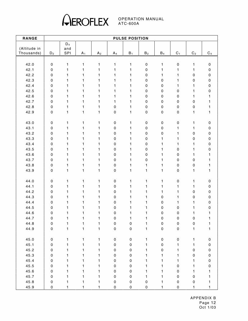
OPERATION MANUAL ATC-600A
APPENDIX B Page 12 Oct 1 /03
RANGE PULSE POSITION
(Al t i tude in Thousands)
D2
D4 and SPI
A1
A2
A4
B1
B2
B4
C1
C2
C4
42.0 0 1 1 1 1 1 0 1 0 1 0
42.1 0 1 1 1 1 1 0 1 1 1 0
42.2 0 1 1 1 1 1 0 1 1 0 0
42.3 0 1 1 1 1 1 0 0 1 0 0
42.4 0 1 1 1 1 1 0 0 1 1 0
42.5 0 1 1 1 1 1 0 0 0 1 0
42.6 0 1 1 1 1 1 0 0 0 1 1
42.7 0 1 1 1 1 1 0 0 0 0 1
42.8 0 1 1 1 0 1 0 0 0 0 1
42.9 0 1 1 1 0 1 0 0 0 1 1
43.0 0 1 1 1 0 1 0 0 0 1 0
43.1 0 1 1 1 0 1 0 0 1 1 0
43.2 0 1 1 1 0 1 0 0 1 0 0
43.3 0 1 1 1 0 1 0 1 1 0 0
43.4 0 1 1 1 0 1 0 1 1 1 0
43.5 0 1 1 1 0 1 0 1 0 1 0
43.6 0 1 1 1 0 1 0 1 0 1 1
43.7 0 1 1 1 0 1 0 1 0 0 1
43.8 0 1 1 1 0 1 1 1 0 0 1
43.9 0 1 1 1 0 1 1 1 0 1 1
44.0 0 1 1 1 0 1 1 1 0 1 0
44.1 0 1 1 1 0 1 1 1 1 1 0
44.2 0 1 1 1 0 1 1 1 1 0 0
44.3 0 1 1 1 0 1 1 0 1 0 0
44.4 0 1 1 1 0 1 1 0 1 1 0
44.5 0 1 1 1 0 1 1 0 0 1 0
44.6 0 1 1 1 0 1 1 0 0 1 1
44.7 0 1 1 1 0 1 1 0 0 0 1
44.8 0 1 1 1 0 0 1 0 0 0 1
44.9 0 1 1 1 0 0 1 0 0 1 1
45.0 0 1 1 1 0 0 1 0 0 1 0
45.1 0 1 1 1 0 0 1 0 1 1 0
45.2 0 1 1 1 0 0 1 0 1 0 0
45.3 0 1 1 1 0 0 1 1 1 0 0
45.4 0 1 1 1 0 0 1 1 1 1 0
45.5 0 1 1 1 0 0 1 1 0 1 0
45.6 0 1 1 1 0 0 1 1 0 1 1
45.7 0 1 1 1 0 0 1 1 0 0 1
45.8 0 1 1 1 0 0 0 1 0 0 1
45.9 0 1 1 1 0 0 0 1 0 1 1

OPERATION MANUAL ATC-600A
APPENDIX B Page 13 Oct 1 /03
RANGE PULSE POSITION
(Al t i tude in Thousands)
D2
D4 and SPI
A1
A2
A4
B1
B2
B4
C1
C2
C4
46.0 0 1 1 1 0 0 0 1 0 1 0
46.1 0 1 1 1 0 0 0 1 1 1 0
46.2 0 1 1 1 0 0 0 1 1 0 0
46.3 0 1 1 1 0 0 0 0 1 0 0
46.4 0 1 1 1 0 0 0 0 1 1 0
46.5 0 1 1 1 0 0 0 0 0 1 0
46.6 0 1 1 1 0 0 0 0 0 1 1
46.7 0 1 1 1 0 0 0 0 0 0 1
46.8 0 1 0 1 0 0 0 0 0 0 1
46.9 0 1 0 1 0 0 0 0 0 1 1
47.0 0 1 0 1 0 0 0 0 0 1 0
47.1 0 1 0 1 0 0 0 0 1 1 0
47.2 0 1 0 1 0 0 0 0 1 0 0
47.3 0 1 0 1 0 0 0 1 1 0 0
47.4 0 1 0 1 0 0 0 1 1 1 0
47.5 0 1 0 1 0 0 0 1 0 1 0
47.6 0 1 0 1 0 0 0 1 0 1 1
47.7 0 1 0 1 0 0 0 1 0 0 1
47.8 0 1 0 1 0 0 1 1 0 0 1
47.9 0 1 0 1 0 0 1 1 0 1 1
48.0 0 1 0 1 0 0 1 1 0 1 0
48.1 0 1 0 1 0 0 1 1 1 1 0
48.2 0 1 0 1 0 0 1 1 1 0 0
48.3 0 1 0 1 0 0 1 0 1 0 0
48.4 0 1 0 1 0 0 1 0 1 1 0
48.5 0 1 0 1 0 0 1 0 0 1 0
48.6 0 1 0 1 0 0 1 0 0 1 1
48.7 0 1 0 1 0 0 1 0 0 0 1
48.8 0 1 0 1 0 1 1 0 0 0 1
48.9 0 1 0 1 0 1 1 0 0 1 1
49.0 0 1 0 1 0 1 1 0 0 1 0
49.1 0 1 0 1 0 1 1 0 1 1 0
49.2 0 1 0 1 0 1 1 0 1 0 0
49.3 0 1 0 1 0 1 1 1 1 0 0
49.4 0 1 0 1 0 1 1 1 1 1 0
49.5 0 1 0 1 0 1 1 1 0 1 0
49.6 0 1 0 1 0 1 1 1 0 1 1
49.7 0 1 0 1 0 1 1 1 0 0 1
49.8 0 1 0 1 0 1 0 1 0 0 1
49.9 0 1 0 1 0 1 0 1 0 1 1

OPERATION MANUAL ATC-600A
APPENDIX B Page 14 Oct 1 /03
RANGE PULSE POSITION
(Al t i tude in Thousands)
D2
D4 and SPI
A1
A2
A4
B1
B2
B4
C1
C2
C4
50.0 0 1 0 1 0 1 0 1 0 1 0
50.1 0 1 0 1 0 1 0 1 1 1 0
50.2 0 1 0 1 0 1 0 1 1 0 0
50.3 0 1 0 1 0 1 0 0 1 0 0
50.4 0 1 0 1 0 1 0 0 1 1 0
50.5 0 1 0 1 0 1 0 0 0 1 0
50.6 0 1 0 1 0 1 0 0 0 1 1
50.7 0 1 0 1 0 1 0 0 0 0 1
50.8 0 1 0 1 1 1 0 0 0 0 1
50.9 0 1 0 1 1 1 0 0 0 1 1
51.0 0 1 0 1 1 1 0 0 0 1 0
51.1 0 1 0 1 1 1 0 0 1 1 0
51.2 0 1 0 1 1 1 0 0 1 0 0
51.3 0 1 0 1 1 1 0 1 1 0 0
51.4 0 1 0 1 1 1 0 1 1 1 0
51.5 0 1 0 1 1 1 0 1 0 1 0
51.6 0 1 0 1 1 1 0 1 0 1 1
51.7 0 1 0 1 1 1 0 1 0 0 1
51.8 0 1 0 1 1 1 1 1 0 0 1
51.9 0 1 0 1 1 1 1 1 0 1 1
52.0 0 1 0 1 1 1 1 1 0 1 0
52.1 0 1 0 1 1 1 1 1 1 1 0
52.2 0 1 0 1 1 1 1 1 1 0 0
52.3 0 1 0 1 1 1 1 0 1 0 0
52.4 0 1 0 1 1 1 1 0 1 1 0
52.5 0 1 0 1 1 1 1 0 0 1 0
52.6 0 1 0 1 1 1 1 0 0 1 1
52.7 0 1 0 1 1 1 1 0 0 0 1
52.8 0 1 0 1 1 0 1 0 0 0 1
52.9 0 1 0 1 1 0 1 0 0 1 1
53.0 0 1 0 1 1 0 1 0 0 1 0
53.1 0 1 0 1 1 0 1 0 1 1 0
53.2 0 1 0 1 1 0 1 0 1 0 0
53.3 0 1 0 1 1 0 1 1 1 0 0
53.4 0 1 0 1 1 0 1 1 1 1 0
53.5 0 1 0 1 1 0 1 1 0 1 0
53.6 0 1 0 1 1 0 1 1 0 1 1
53.7 0 1 0 1 1 0 1 1 0 0 1
53.8 0 1 0 1 1 0 0 1 0 0 1
53.9 0 1 0 1 1 0 0 1 0 1 1

OPERATION MANUAL ATC-600A
APPENDIX B Page 15 Oct 1 /03
RANGE PULSE POSITION
(Al t i tude in Thousands)
D2
D4 and SPI
A1
A2
A4
B1
B2
B4
C1
C2
C4
54.0 0 1 0 1 1 0 0 1 0 1 0
54.1 0 1 0 1 1 0 0 1 1 1 0
54.2 0 1 0 1 1 0 0 1 1 0 0
54.3 0 1 0 1 1 0 0 0 1 0 0
54.4 0 1 0 1 1 0 0 0 1 1 0
54.5 0 1 0 1 1 0 0 0 0 1 0
54.6 0 1 0 1 1 0 0 0 0 1 1
54.7 0 1 0 1 1 0 0 0 0 0 1
54.8 0 1 0 0 1 0 0 0 0 0 1
54.9 0 1 0 0 1 0 0 0 0 1 1
55.0 0 1 0 0 1 0 0 0 0 1 0
55.1 0 1 0 0 1 0 0 0 1 1 0
55.2 0 1 0 0 1 0 0 0 1 0 0
55.3 0 1 0 0 1 0 0 1 1 0 0
55.4 0 1 0 0 1 0 0 1 1 1 0
55.5 0 1 0 0 1 0 0 1 0 1 0
55.6 0 1 0 0 1 0 0 1 0 1 1
55.7 0 1 0 0 1 0 0 1 0 0 1
55.8 0 1 0 0 1 0 1 1 0 0 1
55.9 0 1 0 0 1 0 1 1 0 1 1
56.0 0 1 0 0 1 0 1 1 0 1 0
56.1 0 1 0 0 1 0 1 1 1 1 0
56.2 0 1 0 0 1 0 1 1 1 0 0
56.3 0 1 0 0 1 0 1 0 1 0 0
56.4 0 1 0 0 1 0 1 0 1 1 0
56.5 0 1 0 0 1 0 1 0 0 1 0
56.6 0 1 0 0 1 0 1 0 0 1 1
56.7 0 1 0 0 1 0 1 0 0 0 1
56.8 0 1 0 0 1 1 1 0 0 0 1
56.9 0 1 0 0 1 1 1 0 0 1 1
57.0 0 1 0 0 1 1 1 0 0 1 0
57.1 0 1 0 0 1 1 1 0 1 1 0
57.2 0 1 0 0 1 1 1 0 1 0 0
57.3 0 1 0 0 1 1 1 1 1 0 0
57.4 0 1 0 0 1 1 1 1 1 1 0
57.5 0 1 0 0 1 1 1 1 0 1 0
57.6 0 1 0 0 1 1 1 1 0 1 1
57.7 0 1 0 0 1 1 1 1 0 0 1
57.8 0 1 0 0 1 1 0 1 0 0 1
57.9 0 1 0 0 1 1 0 1 0 1 1

OPERATION MANUAL ATC-600A
APPENDIX B Page 16 Oct 1 /03
RANGE PULSE POSITION
(Al t i tude in Thousands)
D2
D4 and SPI
A1
A2
A4
B1
B2
B4
C1
C2
C4
58.0 0 1 0 0 1 1 0 1 0 1 0
58.1 0 1 0 0 1 1 0 1 1 1 0
58.2 0 1 0 0 1 1 0 1 1 0 0
58.3 0 1 0 0 1 1 0 0 1 0 0
58.4 0 1 0 0 1 1 0 0 1 1 0
58.5 0 1 0 0 1 1 0 0 0 1 0
58.6 0 1 0 0 1 1 0 0 0 1 1
58.7 0 1 0 0 1 1 0 0 0 0 1
58.8 0 1 0 0 0 1 0 0 0 0 1
58.9 0 1 0 0 0 1 0 0 0 1 1
59.0 0 1 0 0 0 1 0 0 0 1 0
59.1 0 1 0 0 0 1 0 0 1 1 0
59.2 0 1 0 0 0 1 0 0 1 0 0
59.3 0 1 0 0 0 1 0 1 1 0 0
59.4 0 1 0 0 0 1 0 1 1 1 0
59.5 0 1 0 0 0 1 0 1 0 1 0
59.6 0 1 0 0 0 1 0 1 0 1 1
59.7 0 1 0 0 0 1 0 1 0 0 1
59.8 0 1 0 0 0 1 1 1 0 0 1
59.9 0 1 0 0 0 1 1 1 0 1 1
60.0 0 1 0 0 0 1 1 1 0 1 0
60.1 0 1 0 0 0 1 1 1 1 1 0
60.2 0 1 0 0 0 1 1 1 1 0 0
60.3 0 1 0 0 0 1 1 0 1 0 0
60.4 0 1 0 0 0 1 1 0 1 1 0
60.5 0 1 0 0 0 1 1 0 0 1 0
60.6 0 1 0 0 0 1 1 0 0 1 1
60.7 0 1 0 0 0 1 1 0 0 0 1
60.8 0 1 0 0 0 0 1 0 0 0 1
60.9 0 1 0 0 0 0 1 0 0 1 1
61.0 0 1 0 0 0 0 1 0 0 1 0
61.1 0 1 0 0 0 0 1 0 1 1 0
61.2 0 1 0 0 0 0 1 0 1 0 0
61.3 0 1 0 0 0 0 1 1 1 0 0
61.4 0 1 0 0 0 0 1 1 1 1 0
61.5 0 1 0 0 0 0 1 1 0 1 0
61.6 0 1 0 0 0 0 1 1 0 1 1
61.7 0 1 0 0 0 0 1 1 0 0 1
61.8 0 1 0 0 0 0 0 1 0 0 1
61.9 0 1 0 0 0 0 0 1 0 1 1
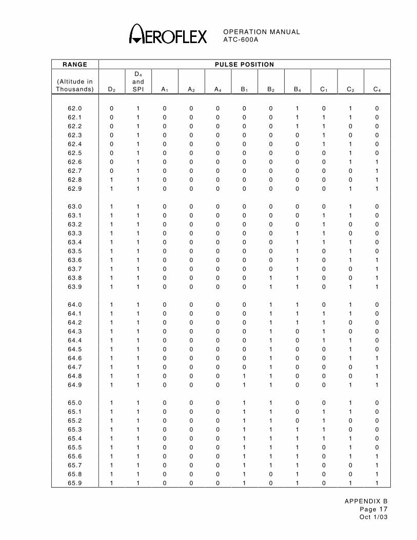
OPERATION MANUAL ATC-600A
APPENDIX B Page 17 Oct 1 /03
RANGE PULSE POSITION
(Al t i tude in Thousands)
D2
D4 and SPI
A1
A2
A4
B1
B2
B4
C1
C2
C4
62.0 0 1 0 0 0 0 0 1 0 1 0
62.1 0 1 0 0 0 0 0 1 1 1 0
62.2 0 1 0 0 0 0 0 1 1 0 0
62.3 0 1 0 0 0 0 0 0 1 0 0
62.4 0 1 0 0 0 0 0 0 1 1 0
62.5 0 1 0 0 0 0 0 0 0 1 0
62.6 0 1 0 0 0 0 0 0 0 1 1
62.7 0 1 0 0 0 0 0 0 0 0 1
62.8 1 1 0 0 0 0 0 0 0 0 1
62.9 1 1 0 0 0 0 0 0 0 1 1
63.0 1 1 0 0 0 0 0 0 0 1 0
63.1 1 1 0 0 0 0 0 0 1 1 0
63.2 1 1 0 0 0 0 0 0 1 0 0
63.3 1 1 0 0 0 0 0 1 1 0 0
63.4 1 1 0 0 0 0 0 1 1 1 0
63.5 1 1 0 0 0 0 0 1 0 1 0
63.6 1 1 0 0 0 0 0 1 0 1 1
63.7 1 1 0 0 0 0 0 1 0 0 1
63.8 1 1 0 0 0 0 1 1 0 0 1
63.9 1 1 0 0 0 0 1 1 0 1 1
64.0 1 1 0 0 0 0 1 1 0 1 0
64.1 1 1 0 0 0 0 1 1 1 1 0
64.2 1 1 0 0 0 0 1 1 1 0 0
64.3 1 1 0 0 0 0 1 0 1 0 0
64.4 1 1 0 0 0 0 1 0 1 1 0
64.5 1 1 0 0 0 0 1 0 0 1 0
64.6 1 1 0 0 0 0 1 0 0 1 1
64.7 1 1 0 0 0 0 1 0 0 0 1
64.8 1 1 0 0 0 1 1 0 0 0 1
64.9 1 1 0 0 0 1 1 0 0 1 1
65.0 1 1 0 0 0 1 1 0 0 1 0
65.1 1 1 0 0 0 1 1 0 1 1 0
65.2 1 1 0 0 0 1 1 0 1 0 0
65.3 1 1 0 0 0 1 1 1 1 0 0
65.4 1 1 0 0 0 1 1 1 1 1 0
65.5 1 1 0 0 0 1 1 1 0 1 0
65.6 1 1 0 0 0 1 1 1 0 1 1
65.7 1 1 0 0 0 1 1 1 0 0 1
65.8 1 1 0 0 0 1 0 1 0 0 1
65.9 1 1 0 0 0 1 0 1 0 1 1
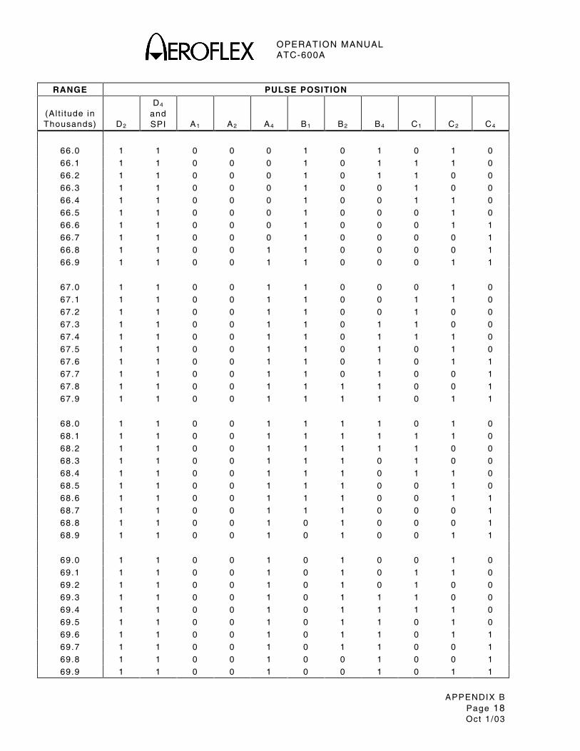
OPERATION MANUAL ATC-600A
APPENDIX B Page 18 Oct 1 /03
RANGE PULSE POSITION
(Al t i tude in Thousands)
D2
D4 and SPI
A1
A2
A4
B1
B2
B4
C1
C2
C4
66.0 1 1 0 0 0 1 0 1 0 1 0
66.1 1 1 0 0 0 1 0 1 1 1 0
66.2 1 1 0 0 0 1 0 1 1 0 0
66.3 1 1 0 0 0 1 0 0 1 0 0
66.4 1 1 0 0 0 1 0 0 1 1 0
66.5 1 1 0 0 0 1 0 0 0 1 0
66.6 1 1 0 0 0 1 0 0 0 1 1
66.7 1 1 0 0 0 1 0 0 0 0 1
66.8 1 1 0 0 1 1 0 0 0 0 1
66.9 1 1 0 0 1 1 0 0 0 1 1
67.0 1 1 0 0 1 1 0 0 0 1 0
67.1 1 1 0 0 1 1 0 0 1 1 0
67.2 1 1 0 0 1 1 0 0 1 0 0
67.3 1 1 0 0 1 1 0 1 1 0 0
67.4 1 1 0 0 1 1 0 1 1 1 0
67.5 1 1 0 0 1 1 0 1 0 1 0
67.6 1 1 0 0 1 1 0 1 0 1 1
67.7 1 1 0 0 1 1 0 1 0 0 1
67.8 1 1 0 0 1 1 1 1 0 0 1
67.9 1 1 0 0 1 1 1 1 0 1 1
68.0 1 1 0 0 1 1 1 1 0 1 0
68.1 1 1 0 0 1 1 1 1 1 1 0
68.2 1 1 0 0 1 1 1 1 1 0 0
68.3 1 1 0 0 1 1 1 0 1 0 0
68.4 1 1 0 0 1 1 1 0 1 1 0
68.5 1 1 0 0 1 1 1 0 0 1 0
68.6 1 1 0 0 1 1 1 0 0 1 1
68.7 1 1 0 0 1 1 1 0 0 0 1
68.8 1 1 0 0 1 0 1 0 0 0 1
68.9 1 1 0 0 1 0 1 0 0 1 1
69.0 1 1 0 0 1 0 1 0 0 1 0
69.1 1 1 0 0 1 0 1 0 1 1 0
69.2 1 1 0 0 1 0 1 0 1 0 0
69.3 1 1 0 0 1 0 1 1 1 0 0
69.4 1 1 0 0 1 0 1 1 1 1 0
69.5 1 1 0 0 1 0 1 1 0 1 0
69.6 1 1 0 0 1 0 1 1 0 1 1
69.7 1 1 0 0 1 0 1 1 0 0 1
69.8 1 1 0 0 1 0 0 1 0 0 1
69.9 1 1 0 0 1 0 0 1 0 1 1

OPERATION MANUAL ATC-600A
APPENDIX B Page 19 Oct 1 /03
RANGE PULSE POSITION
(Al t i tude in Thousands)
D2
D4 and SPI
A1
A2
A4
B1
B2
B4
C1
C2
C4
70.0 1 1 0 0 1 0 0 1 0 1 0
70.1 1 1 0 0 1 0 0 1 1 1 0
70.2 1 1 0 0 1 0 0 1 1 0 0
70.3 1 1 0 0 1 0 0 0 1 0 0
70.4 1 1 0 0 1 0 0 0 1 1 0
70.5 1 1 0 0 1 0 0 0 0 1 0
70.6 1 1 0 0 1 0 0 0 0 1 1
70.7 1 1 0 0 1 0 0 0 0 0 1
70.8 1 1 0 1 1 0 0 0 0 0 1
70.9 1 1 0 1 1 0 0 0 0 1 1
71.0 1 1 0 1 1 0 0 0 0 1 0
71.1 1 1 0 1 1 0 0 0 1 1 0
71.2 1 1 0 1 1 0 0 0 1 0 0
71.3 1 1 0 1 1 0 0 1 1 0 0
71.4 1 1 0 1 1 0 0 1 1 1 0
71.5 1 1 0 1 1 0 0 1 0 1 0
71.6 1 1 0 1 1 0 0 1 0 1 1
71.7 1 1 0 1 1 0 0 1 0 0 1
71.8 1 1 0 1 1 0 1 1 0 0 1
71.9 1 1 0 1 1 0 1 1 0 1 1
72.0 1 1 0 1 1 0 1 1 0 1 0
72.1 1 1 0 1 1 0 1 1 1 1 0
72.2 1 1 0 1 1 0 1 1 1 0 0
72.3 1 1 0 1 1 0 1 0 1 0 0
72.4 1 1 0 1 1 0 1 0 1 1 0
72.5 1 1 0 1 1 0 1 0 0 1 0
72.6 1 1 0 1 1 0 1 0 0 1 1
72.7 1 1 0 1 1 0 1 0 0 0 1
72.8 1 1 0 1 1 1 1 0 0 0 1
72.9 1 1 0 1 1 1 1 0 0 1 1
73.0 1 1 0 1 1 1 1 0 0 1 0
73.1 1 1 0 1 1 1 1 0 1 1 0
73.2 1 1 0 1 1 1 1 0 1 0 0
73.3 1 1 0 1 1 1 1 1 1 0 0
73.4 1 1 0 1 1 1 1 1 1 1 0
73.5 1 1 0 1 1 1 1 1 0 1 0
73.6 1 1 0 1 1 1 1 1 0 1 1
73.7 1 1 0 1 1 1 1 1 0 0 1
73.8 1 1 0 1 1 1 0 1 0 0 1
73.9 1 1 0 1 1 1 0 1 0 1 1

OPERATION MANUAL ATC-600A
APPENDIX B Page 20 Oct 1 /03
RANGE PULSE POSITION
(Al t i tude in Thousands)
D2
D4 and SPI
A1
A2
A4
B1
B2
B4
C1
C2
C4
74.0 1 1 0 1 1 1 0 1 0 1 0
74.1 1 1 0 1 1 1 0 1 1 1 0
74.2 1 1 0 1 1 1 0 1 1 0 0
74.3 1 1 0 1 1 1 0 0 1 0 0
74.4 1 1 0 1 1 1 0 0 1 1 0
74.5 1 1 0 1 1 1 0 0 0 1 0
74.6 1 1 0 1 1 1 0 0 0 1 1
74.7 1 1 0 1 1 1 0 0 0 0 1
74.8 1 1 0 1 0 1 0 0 0 0 1
74.9 1 1 0 1 0 1 0 0 0 1 1
75.0 1 1 0 1 0 1 0 0 0 1 0
75.1 1 1 0 1 0 1 0 0 1 1 0
75.2 1 1 0 1 0 1 0 0 1 0 0
75.3 1 1 0 1 0 1 0 1 1 0 0
75.4 1 1 0 1 0 1 0 1 1 1 0
75.5 1 1 0 1 0 1 0 1 0 1 0
75.6 1 1 0 1 0 1 0 1 0 1 1
75.7 1 1 0 1 0 1 0 1 0 0 1
75.8 1 1 0 1 0 1 1 1 0 0 1
75.9 1 1 0 1 0 1 1 1 0 1 1
76.0 1 1 0 1 0 1 1 1 0 1 0
76.1 1 1 0 1 0 1 1 1 1 1 0
76.2 1 1 0 1 0 1 1 1 1 0 0
76.3 1 1 0 1 0 1 1 0 1 0 0
76.4 1 1 0 1 0 1 1 0 1 1 0
76.5 1 1 0 1 0 1 1 0 0 1 0
76.6 1 1 0 1 0 1 1 0 0 1 1
76.7 1 1 0 1 0 1 1 0 0 0 1
76.8 1 1 0 1 0 0 1 0 0 0 1
76.9 1 1 0 1 0 0 1 0 0 1 1
77.0 1 1 0 1 0 0 1 0 0 1 0
77.1 1 1 0 1 0 0 1 0 1 1 0
77.2 1 1 0 1 0 0 1 0 1 0 0
77.3 1 1 0 1 0 0 1 1 1 0 0
77.4 1 1 0 1 0 0 1 1 1 1 0
77.5 1 1 0 1 0 0 1 1 0 1 0
77.6 1 1 0 1 0 0 1 1 0 1 1
77.7 1 1 0 1 0 0 1 1 0 0 1
77.8 1 1 0 1 0 0 0 1 0 0 1
77.9 1 1 0 1 0 0 0 1 0 1 1

OPERATION MANUAL ATC-600A
APPENDIX B Page 21 Oct 1 /03
RANGE PULSE POSITION
(Al t i tude in Thousands)
D2
D4 and SPI
A1
A2
A4
B1
B2
B4
C1
C2
C4
78.0 1 1 0 1 0 0 0 1 0 1 0
78.1 1 1 0 1 0 0 0 1 1 1 0
78.2 1 1 0 1 0 0 0 1 1 0 0
78.3 1 1 0 1 0 0 0 0 1 0 0
78.4 1 1 0 1 0 0 0 0 1 1 0
78.5 1 1 0 1 0 0 0 0 0 1 0
78.6 1 1 0 1 0 0 0 0 0 1 1
78.7 1 1 0 1 0 0 0 0 0 0 1
78.8 1 1 1 1 0 0 0 0 0 0 1
78.9 1 1 1 1 0 0 0 0 0 1 1
79.0 1 1 1 1 0 0 0 0 0 1 0
79.1 1 1 1 1 0 0 0 0 1 1 0
79.2 1 1 1 1 0 0 0 0 1 0 0
79.3 1 1 1 1 0 0 0 1 1 0 0
79.4 1 1 1 1 0 0 0 1 1 1 0
79.5 1 1 1 1 0 0 0 1 0 1 0
79.6 1 1 1 1 0 0 0 1 0 1 1
79.7 1 1 1 1 0 0 0 1 0 0 1
79.8 1 1 1 1 0 0 1 1 0 0 1
79.9 1 1 1 1 0 0 1 1 0 1 1
80.0 1 1 1 1 0 0 1 1 0 1 0
80.1 1 1 1 1 0 0 1 1 1 1 0
80.2 1 1 1 1 0 0 1 1 1 0 0
80.3 1 1 1 1 0 0 1 0 1 0 0
80.4 1 1 1 1 0 0 1 0 1 1 0
80.5 1 1 1 1 0 0 1 0 0 1 0
80.6 1 1 1 1 0 0 1 0 0 1 1
80.7 1 1 1 1 0 0 1 0 0 0 1
80.8 1 1 1 1 0 1 1 0 0 0 1
80.9 1 1 1 1 0 1 1 0 0 1 1
81.0 1 1 1 1 0 1 1 0 0 1 0
81.1 1 1 1 1 0 1 1 0 1 1 0
81.2 1 1 1 1 0 1 1 0 1 0 0
81.3 1 1 1 1 0 1 1 1 1 0 0
81.4 1 1 1 1 0 1 1 1 1 1 0
81.5 1 1 1 1 0 1 1 1 0 1 0
81.6 1 1 1 1 0 1 1 1 0 1 1
81.7 1 1 1 1 0 1 1 1 0 0 1
81.8 1 1 1 1 0 1 0 1 0 0 1
81.9 1 1 1 1 0 1 0 1 0 1 1
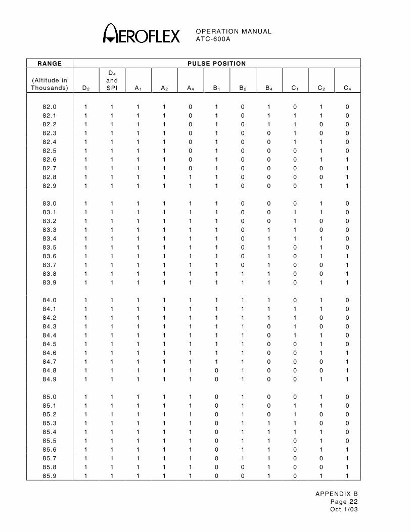
OPERATION MANUAL ATC-600A
APPENDIX B Page 22 Oct 1 /03
RANGE PULSE POSITION
(Al t i tude in Thousands)
D2
D4 and SPI
A1
A2
A4
B1
B2
B4
C1
C2
C4
82.0 1 1 1 1 0 1 0 1 0 1 0
82.1 1 1 1 1 0 1 0 1 1 1 0
82.2 1 1 1 1 0 1 0 1 1 0 0
82.3 1 1 1 1 0 1 0 0 1 0 0
82.4 1 1 1 1 0 1 0 0 1 1 0
82.5 1 1 1 1 0 1 0 0 0 1 0
82.6 1 1 1 1 0 1 0 0 0 1 1
82.7 1 1 1 1 0 1 0 0 0 0 1
82.8 1 1 1 1 1 1 0 0 0 0 1
82.9 1 1 1 1 1 1 0 0 0 1 1
83.0 1 1 1 1 1 1 0 0 0 1 0
83.1 1 1 1 1 1 1 0 0 1 1 0
83.2 1 1 1 1 1 1 0 0 1 0 0
83.3 1 1 1 1 1 1 0 1 1 0 0
83.4 1 1 1 1 1 1 0 1 1 1 0
83.5 1 1 1 1 1 1 0 1 0 1 0
83.6 1 1 1 1 1 1 0 1 0 1 1
83.7 1 1 1 1 1 1 0 1 0 0 1
83.8 1 1 1 1 1 1 1 1 0 0 1
83.9 1 1 1 1 1 1 1 1 0 1 1
84.0 1 1 1 1 1 1 1 1 0 1 0
84.1 1 1 1 1 1 1 1 1 1 1 0
84.2 1 1 1 1 1 1 1 1 1 0 0
84.3 1 1 1 1 1 1 1 0 1 0 0
84.4 1 1 1 1 1 1 1 0 1 1 0
84.5 1 1 1 1 1 1 1 0 0 1 0
84.6 1 1 1 1 1 1 1 0 0 1 1
84.7 1 1 1 1 1 1 1 0 0 0 1
84.8 1 1 1 1 1 0 1 0 0 0 1
84.9 1 1 1 1 1 0 1 0 0 1 1
85.0 1 1 1 1 1 0 1 0 0 1 0
85.1 1 1 1 1 1 0 1 0 1 1 0
85.2 1 1 1 1 1 0 1 0 1 0 0
85.3 1 1 1 1 1 0 1 1 1 0 0
85.4 1 1 1 1 1 0 1 1 1 1 0
85.5 1 1 1 1 1 0 1 1 0 1 0
85.6 1 1 1 1 1 0 1 1 0 1 1
85.7 1 1 1 1 1 0 1 1 0 0 1
85.8 1 1 1 1 1 0 0 1 0 0 1
85.9 1 1 1 1 1 0 0 1 0 1 1
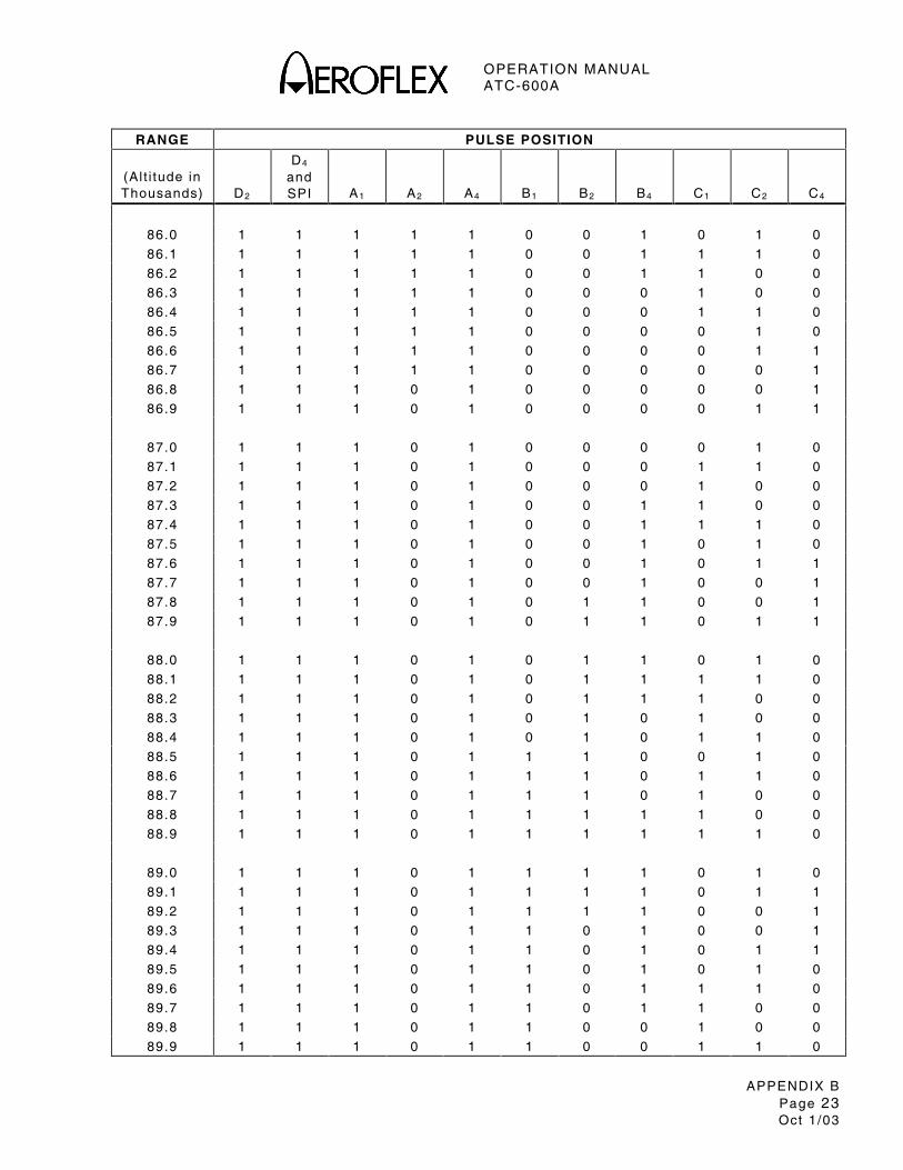
OPERATION MANUAL ATC-600A
APPENDIX B Page 23 Oct 1 /03
RANGE PULSE POSITION
(Al t i tude in Thousands)
D2
D4 and SPI
A1
A2
A4
B1
B2
B4
C1
C2
C4
86.0 1 1 1 1 1 0 0 1 0 1 0
86.1 1 1 1 1 1 0 0 1 1 1 0
86.2 1 1 1 1 1 0 0 1 1 0 0
86.3 1 1 1 1 1 0 0 0 1 0 0
86.4 1 1 1 1 1 0 0 0 1 1 0
86.5 1 1 1 1 1 0 0 0 0 1 0
86.6 1 1 1 1 1 0 0 0 0 1 1
86.7 1 1 1 1 1 0 0 0 0 0 1
86.8 1 1 1 0 1 0 0 0 0 0 1
86.9 1 1 1 0 1 0 0 0 0 1 1
87.0 1 1 1 0 1 0 0 0 0 1 0
87.1 1 1 1 0 1 0 0 0 1 1 0
87.2 1 1 1 0 1 0 0 0 1 0 0
87.3 1 1 1 0 1 0 0 1 1 0 0
87.4 1 1 1 0 1 0 0 1 1 1 0
87.5 1 1 1 0 1 0 0 1 0 1 0
87.6 1 1 1 0 1 0 0 1 0 1 1
87.7 1 1 1 0 1 0 0 1 0 0 1
87.8 1 1 1 0 1 0 1 1 0 0 1
87.9 1 1 1 0 1 0 1 1 0 1 1
88.0 1 1 1 0 1 0 1 1 0 1 0
88.1 1 1 1 0 1 0 1 1 1 1 0
88.2 1 1 1 0 1 0 1 1 1 0 0
88.3 1 1 1 0 1 0 1 0 1 0 0
88.4 1 1 1 0 1 0 1 0 1 1 0
88.5 1 1 1 0 1 1 1 0 0 1 0
88.6 1 1 1 0 1 1 1 0 1 1 0
88.7 1 1 1 0 1 1 1 0 1 0 0
88.8 1 1 1 0 1 1 1 1 1 0 0
88.9 1 1 1 0 1 1 1 1 1 1 0
89.0 1 1 1 0 1 1 1 1 0 1 0
89.1 1 1 1 0 1 1 1 1 0 1 1
89.2 1 1 1 0 1 1 1 1 0 0 1
89.3 1 1 1 0 1 1 0 1 0 0 1
89.4 1 1 1 0 1 1 0 1 0 1 1
89.5 1 1 1 0 1 1 0 1 0 1 0
89.6 1 1 1 0 1 1 0 1 1 1 0
89.7 1 1 1 0 1 1 0 1 1 0 0
89.8 1 1 1 0 1 1 0 0 1 0 0
89.9 1 1 1 0 1 1 0 0 1 1 0
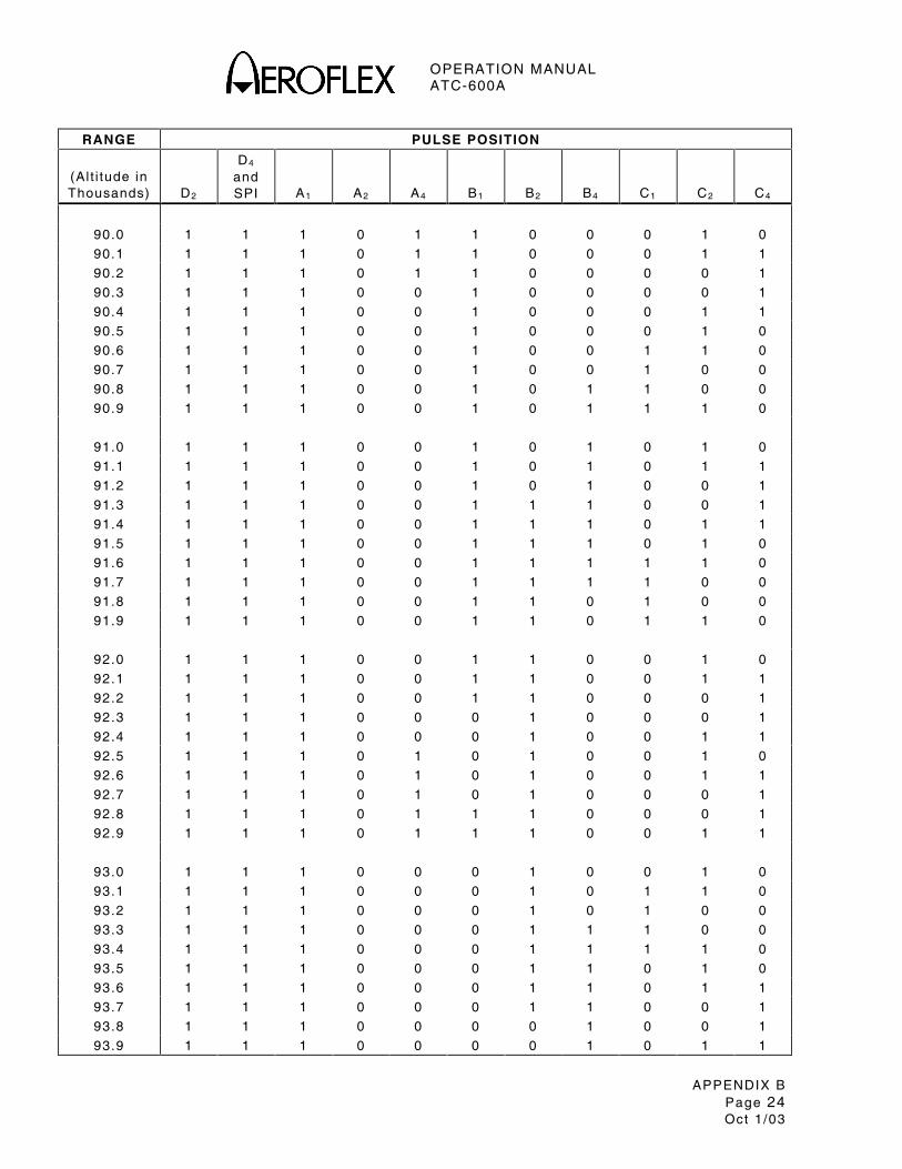
OPERATION MANUAL ATC-600A
APPENDIX B Page 24 Oct 1 /03
RANGE PULSE POSITION
(Al t i tude in Thousands)
D2
D4 and SPI
A1
A2
A4
B1
B2
B4
C1
C2
C4
90.0 1 1 1 0 1 1 0 0 0 1 0
90.1 1 1 1 0 1 1 0 0 0 1 1
90.2 1 1 1 0 1 1 0 0 0 0 1
90.3 1 1 1 0 0 1 0 0 0 0 1
90.4 1 1 1 0 0 1 0 0 0 1 1
90.5 1 1 1 0 0 1 0 0 0 1 0
90.6 1 1 1 0 0 1 0 0 1 1 0
90.7 1 1 1 0 0 1 0 0 1 0 0
90.8 1 1 1 0 0 1 0 1 1 0 0
90.9 1 1 1 0 0 1 0 1 1 1 0
91.0 1 1 1 0 0 1 0 1 0 1 0
91.1 1 1 1 0 0 1 0 1 0 1 1
91.2 1 1 1 0 0 1 0 1 0 0 1
91.3 1 1 1 0 0 1 1 1 0 0 1
91.4 1 1 1 0 0 1 1 1 0 1 1
91.5 1 1 1 0 0 1 1 1 0 1 0
91.6 1 1 1 0 0 1 1 1 1 1 0
91.7 1 1 1 0 0 1 1 1 1 0 0
91.8 1 1 1 0 0 1 1 0 1 0 0
91.9 1 1 1 0 0 1 1 0 1 1 0
92.0 1 1 1 0 0 1 1 0 0 1 0
92.1 1 1 1 0 0 1 1 0 0 1 1
92.2 1 1 1 0 0 1 1 0 0 0 1
92.3 1 1 1 0 0 0 1 0 0 0 1
92.4 1 1 1 0 0 0 1 0 0 1 1
92.5 1 1 1 0 1 0 1 0 0 1 0
92.6 1 1 1 0 1 0 1 0 0 1 1
92.7 1 1 1 0 1 0 1 0 0 0 1
92.8 1 1 1 0 1 1 1 0 0 0 1
92.9 1 1 1 0 1 1 1 0 0 1 1
93.0 1 1 1 0 0 0 1 0 0 1 0
93.1 1 1 1 0 0 0 1 0 1 1 0
93.2 1 1 1 0 0 0 1 0 1 0 0
93.3 1 1 1 0 0 0 1 1 1 0 0
93.4 1 1 1 0 0 0 1 1 1 1 0
93.5 1 1 1 0 0 0 1 1 0 1 0
93.6 1 1 1 0 0 0 1 1 0 1 1
93.7 1 1 1 0 0 0 1 1 0 0 1
93.8 1 1 1 0 0 0 0 1 0 0 1
93.9 1 1 1 0 0 0 0 1 0 1 1

OPERATION MANUAL ATC-600A
APPENDIX B Page 25 Oct 1 /03
RANGE PULSE POSITION
(Al t i tude in Thousands)
D2
D4 and SPI
A1
A2
A4
B1
B2
B4
C1
C2
C4
94.0 1 1 1 0 0 0 0 1 0 1 0
94.1 1 1 1 0 0 0 0 1 1 1 0
94.2 1 1 1 0 0 0 0 1 1 0 0
94.3 1 1 1 0 0 0 0 0 1 0 0
94.4 1 1 1 0 0 0 0 0 1 1 0
94.5 1 1 1 0 0 0 0 0 0 1 0
94.6 1 1 1 0 0 0 0 0 0 1 1
94.7 1 1 1 0 0 0 0 0 0 0 1
94.8 1 0 1 0 0 0 0 0 0 0 1
94.9 1 0 1 0 0 0 0 0 0 1 1
95.0 1 0 1 0 0 0 0 0 0 1 0
95.1 1 0 1 0 0 0 0 0 1 1 0
95.2 1 0 1 0 0 0 0 0 1 0 0
95.3 1 0 1 0 0 0 0 1 1 0 0
95.4 1 0 1 0 0 0 0 1 1 1 0
95.5 1 0 1 0 0 0 0 1 0 1 0
95.6 1 0 1 0 0 0 0 1 0 1 1
95.7 1 0 1 0 0 0 0 1 0 0 1
95.8 1 0 1 0 0 0 1 1 0 0 1
95.9 1 0 1 0 0 0 1 1 0 1 1
96.0 1 0 1 0 0 0 1 1 0 1 0
96.1 1 0 1 0 0 0 1 1 1 1 0
96.2 1 0 1 0 0 0 1 1 1 0 0
96.3 1 0 1 0 0 0 1 0 1 0 0
96.4 1 0 1 0 0 0 1 0 1 1 0
96.5 1 0 1 0 0 0 1 0 0 1 0
96.6 1 0 1 0 0 0 1 0 0 1 1
96.7 1 0 1 0 0 0 1 0 0 0 1
96.8 1 0 1 0 0 1 1 0 0 0 1
96.9 1 0 1 0 0 1 1 0 0 1 1
97.0 1 0 1 0 0 1 1 0 0 1 0
97.1 1 0 1 0 0 1 1 0 1 1 0
97.2 1 0 1 0 0 1 1 0 1 0 0
97.3 1 0 1 0 0 1 1 1 1 0 0
97.4 1 0 1 0 0 1 1 1 1 1 0
97.5 1 0 1 0 0 1 1 1 0 1 0
97.6 1 0 1 0 0 1 1 1 0 1 1
97.7 1 0 1 0 0 1 1 1 0 0 1
97.8 1 0 1 0 0 1 0 1 0 0 1
97.9 1 0 1 0 0 1 0 1 0 1 1

OPERATION MANUAL ATC-600A
APPENDIX B Page 26 Oct 1 /03
RANGE PULSE POSITION
(Al t i tude in Thousands)
D2
D4 and SPI
A1
A2
A4
B1
B2
B4
C1
C2
C4
98.0 1 0 1 0 0 1 0 1 0 1 0
98.1 1 0 1 0 0 1 0 1 1 1 0
98.2 1 0 1 0 0 1 0 1 1 0 0
98.3 1 0 1 0 0 1 0 0 1 0 0
98.4 1 0 1 0 0 1 0 0 1 1 0
98.5 1 0 1 0 0 1 0 0 0 1 0
98.6 1 0 1 0 0 1 0 0 0 1 1
98.7 1 0 1 0 0 1 0 0 0 0 1
98.8 1 0 1 0 1 1 0 0 0 0 1
98.9 1 0 1 0 1 1 0 0 0 1 1
99.0 1 0 1 0 1 1 0 0 0 1 0
99.1 1 0 1 0 1 1 0 0 1 1 0
99.2 1 0 1 0 1 1 0 0 1 0 0
99.3 1 0 1 0 1 1 0 1 1 0 0
99.4 1 0 1 0 1 1 0 1 1 1 0
99.5 1 0 1 0 1 1 0 1 0 1 0
99.6 1 0 1 0 1 1 0 1 0 1 1
99.7 1 0 1 0 1 1 0 1 0 0 1
99.8 1 0 1 0 1 1 1 1 0 0 1
99.9 1 0 1 0 1 1 1 1 0 1 1
100.0 1 0 1 0 1 1 1 1 0 1 0
100.1 1 0 1 0 1 1 1 1 1 1 0
100.2 1 0 1 0 1 1 1 1 1 0 0
100.3 1 0 1 0 1 1 1 0 1 0 0
100.4 1 0 1 0 1 1 1 0 1 1 0
100.5 1 0 1 0 1 1 1 0 0 1 0
100.6 1 0 1 0 1 1 1 0 0 1 1
100.7 1 0 1 0 1 1 1 0 0 0 1
100.8 1 0 1 0 1 0 1 0 0 0 1
100.9 1 0 1 0 1 0 1 0 0 1 1
101.0 1 0 1 0 1 0 1 0 0 1 0
101.1 1 0 1 0 1 0 1 0 1 1 0
101.2 1 0 1 0 1 0 1 0 1 0 0
101.3 1 0 1 0 1 0 1 1 1 0 0
101.4 1 0 1 0 1 0 1 1 1 1 0
101.5 1 0 1 0 1 0 1 1 0 1 0
101.6 1 0 1 0 1 0 1 1 0 1 1
101.7 1 0 1 0 1 0 1 1 0 0 1
101.8 1 0 1 0 1 0 0 1 0 0 1
101.9 1 0 1 0 1 0 0 1 0 1 1

OPERATION MANUAL ATC-600A
APPENDIX B Page 27 Oct 1 /03
RANGE PULSE POSITION
(Al t i tude in Thousands)
D2
D4 and SPI
A1
A2
A4
B1
B2
B4
C1
C2
C4
102.0 1 0 1 0 1 0 0 1 0 1 0
102.1 1 0 1 0 1 0 0 1 1 1 0
102.2 1 0 1 0 1 0 0 1 1 0 0
102.3 1 0 1 0 1 0 0 0 1 0 0
102.4 1 0 1 0 1 0 0 0 1 1 0
102.5 1 0 1 0 1 0 0 0 0 1 0
102.6 1 0 1 0 1 0 0 0 0 1 1
102.7 1 0 1 0 1 0 0 0 0 0 1
102.8 1 0 1 1 1 0 0 0 0 0 1
102.9 1 0 1 1 1 0 0 0 0 1 1
103.0 1 0 1 1 1 0 0 0 0 1 0
103.1 1 0 1 1 1 0 0 0 1 1 0
103.2 1 0 1 1 1 0 0 0 1 0 0
103.3 1 0 1 1 1 0 0 1 1 0 0
103.4 1 0 1 1 1 0 0 1 1 1 0
103.5 1 0 1 1 1 0 0 1 0 1 0
103.6 1 0 1 1 1 0 0 1 0 1 1
103.7 1 0 1 1 1 0 0 1 0 0 1
103.8 1 0 1 1 1 0 1 1 0 0 1
103.9 1 0 1 1 1 0 1 1 0 1 1
104.0 1 0 1 1 1 0 1 1 0 1 0
104.1 1 0 1 1 1 0 1 1 1 1 0
104.2 1 0 1 1 1 0 1 1 1 0 0
104.3 1 0 1 1 1 0 1 0 1 0 0
104.4 1 0 1 1 1 0 1 0 1 1 0
104.5 1 0 1 1 1 0 1 0 0 1 0
104.6 1 0 1 1 1 0 1 0 0 1 1
104.7 1 0 1 1 1 0 1 0 0 0 1
104.8 1 0 1 1 1 0 1 0 0 0 1
104.9 1 0 1 1 1 1 1 0 0 1 1
105.0 1 0 1 1 1 1 1 0 0 1 0
105.1 1 0 1 1 1 1 1 0 1 1 0
105.2 1 0 1 1 1 1 1 0 1 0 0
105.3 1 0 1 1 1 1 1 1 1 0 0
105.4 1 0 1 1 1 1 1 1 1 1 0
105.5 1 0 1 1 1 1 1 1 0 1 0
105.6 1 0 1 1 1 1 1 1 0 1 1
105.7 1 0 1 1 1 1 1 1 0 0 1
105.8 1 0 1 1 1 1 0 1 0 0 1
105.9 1 0 1 1 1 1 0 1 0 1 1

OPERATION MANUAL ATC-600A
APPENDIX B Page 28 Oct 1 /03
RANGE PULSE POSITION
(Al t i tude in Thousands)
D2
D4 and SPI
A1
A2
A4
B1
B2
B4
C1
C2
C4
106.0 1 0 1 1 1 1 0 1 0 1 0
106.1 1 0 1 1 1 1 0 1 1 1 0
106.2 1 0 1 1 1 1 0 1 1 0 0
106.3 1 0 1 1 1 1 0 0 1 0 0
106.4 1 0 1 1 1 1 0 0 1 1 0
106.5 1 0 1 1 1 1 0 0 0 1 0
106.6 1 0 1 1 1 1 0 0 0 1 1
106.7 1 0 1 1 1 1 0 0 0 0 1
106.8 1 0 1 1 0 1 0 0 0 0 1
106.9 1 0 1 1 0 1 0 0 0 1 1
107.0 1 0 1 1 0 1 0 0 0 1 0
107.1 1 0 1 1 0 1 0 0 1 1 0
107.2 1 0 1 1 0 1 0 0 1 0 0
107.3 1 0 1 1 0 1 0 1 1 0 0
107.4 1 0 1 1 0 1 0 1 1 1 0
107.5 1 0 1 1 0 1 0 1 0 1 0
107.6 1 0 1 1 0 1 0 1 0 1 1
107.7 1 0 1 1 0 1 0 1 0 0 1
107.8 1 0 1 1 0 1 1 1 0 0 1
107.9 1 0 1 1 0 1 1 1 0 1 1
108.0 1 0 1 1 0 1 1 1 0 1 0
108.1 1 0 1 1 0 1 1 1 1 1 0
108.2 1 0 1 1 0 1 1 1 1 0 0
108.3 1 0 1 1 0 1 1 0 1 0 0
108.4 1 0 1 1 0 1 1 0 1 1 0
108.5 1 0 1 1 0 1 1 0 0 1 0
108.6 1 0 1 1 0 1 1 0 0 1 1
108.7 1 0 1 1 0 1 1 0 0 0 1
108.8 1 0 1 1 0 0 1 0 0 0 1
108.9 1 0 1 1 0 0 1 0 0 1 1
109.0 1 0 1 1 0 0 1 0 0 1 0
109.1 1 0 1 1 0 0 1 0 1 1 0
109.2 1 0 1 1 0 0 1 0 1 0 0
109.3 1 0 1 1 0 0 1 1 1 0 0
109.4 1 0 1 1 0 0 1 1 1 1 0
109.5 1 0 1 1 0 0 1 1 0 1 0
109.6 1 0 1 1 0 0 1 1 0 1 1
109.7 1 0 1 1 0 0 1 1 0 0 1
109.8 1 0 1 1 0 0 0 1 0 0 1
109.9 1 0 1 1 0 0 0 1 0 1 1

OPERATION MANUAL ATC-600A
APPENDIX B Page 29 Oct 1 /03
RANGE PULSE POSITION
(Al t i tude in Thousands)
D2
D4 and SPI
A1
A2
A4
B1
B2
B4
C1
C2
C4
110.0 1 0 1 1 0 0 0 1 0 1 0
110.1 1 0 1 1 0 0 0 1 1 1 0
110.2 1 0 1 1 0 0 0 1 1 0 0
110.3 1 0 1 1 0 0 0 0 1 0 0
110.4 1 0 1 1 0 0 0 0 1 1 0
110.5 1 0 1 1 0 0 0 0 0 1 0
110.6 1 0 1 1 0 0 0 0 0 1 1
110.7 1 0 1 1 0 0 0 0 0 0 1
110.8 1 0 0 1 0 0 0 0 0 0 1
110.9 1 0 0 1 0 0 0 0 0 1 1
111.0 1 0 0 1 0 0 0 0 0 1 0
111.1 1 0 0 1 0 0 0 0 1 1 0
111.2 1 0 0 1 0 0 0 0 1 0 0
111.3 1 0 0 1 0 0 0 1 1 0 0
111.4 1 0 0 1 0 0 0 1 1 1 0
111.5 1 0 0 1 0 0 0 1 0 1 0
111.6 1 0 0 1 0 0 0 1 0 1 1
111.7 1 0 0 1 0 0 0 1 0 0 1
111.8 1 0 0 1 0 0 1 1 0 0 1
111.9 1 0 0 1 0 0 1 1 0 1 1
112.0 1 0 0 1 0 0 1 1 0 1 0
112.1 1 0 0 1 0 0 1 1 1 1 0
112.2 1 0 0 1 0 0 1 1 1 0 0
112.3 1 0 0 1 0 0 1 0 1 0 0
112.4 1 0 0 1 0 0 1 0 1 1 0
112.5 1 0 0 1 0 0 1 0 0 1 0
112.6 1 0 0 1 0 0 1 0 0 1 1
112.7 1 0 0 1 0 0 1 0 0 0 1
112.8 1 0 0 1 0 1 1 0 0 0 1
112.9 1 0 0 1 0 1 1 0 0 1 1
113.0 1 0 0 1 0 1 1 0 0 1 0
113.1 1 0 0 1 0 1 1 0 1 1 0
113.2 1 0 0 1 0 1 1 0 1 0 0
113.3 1 0 0 1 0 1 1 1 1 0 0
113.4 1 0 0 1 0 1 1 1 1 1 0
113.5 1 0 0 1 0 1 1 1 0 1 0
113.6 1 0 0 1 0 1 1 1 0 1 1
113.7 1 0 0 1 0 1 1 1 0 0 1
113.8 1 0 0 1 0 1 0 1 0 0 1
113.9 1 0 0 1 0 1 0 1 0 1 1
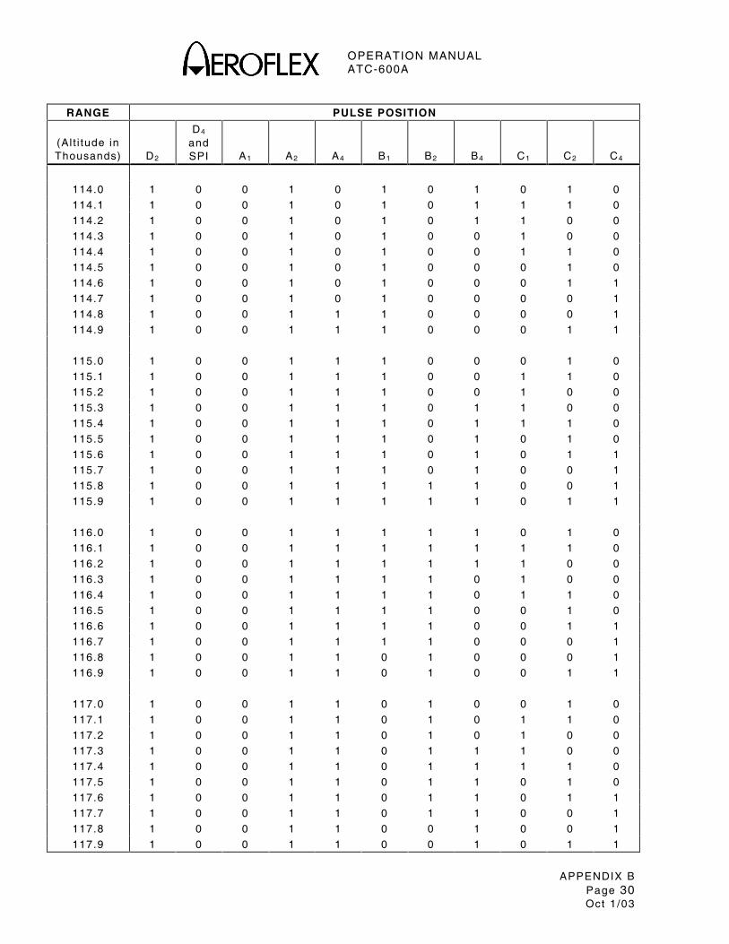
OPERATION MANUAL ATC-600A
APPENDIX B Page 30 Oct 1 /03
RANGE PULSE POSITION
(Al t i tude in Thousands)
D2
D4 and SPI
A1
A2
A4
B1
B2
B4
C1
C2
C4
114.0 1 0 0 1 0 1 0 1 0 1 0
114.1 1 0 0 1 0 1 0 1 1 1 0
114.2 1 0 0 1 0 1 0 1 1 0 0
114.3 1 0 0 1 0 1 0 0 1 0 0
114.4 1 0 0 1 0 1 0 0 1 1 0
114.5 1 0 0 1 0 1 0 0 0 1 0
114.6 1 0 0 1 0 1 0 0 0 1 1
114.7 1 0 0 1 0 1 0 0 0 0 1
114.8 1 0 0 1 1 1 0 0 0 0 1
114.9 1 0 0 1 1 1 0 0 0 1 1
115.0 1 0 0 1 1 1 0 0 0 1 0
115.1 1 0 0 1 1 1 0 0 1 1 0
115.2 1 0 0 1 1 1 0 0 1 0 0
115.3 1 0 0 1 1 1 0 1 1 0 0
115.4 1 0 0 1 1 1 0 1 1 1 0
115.5 1 0 0 1 1 1 0 1 0 1 0
115.6 1 0 0 1 1 1 0 1 0 1 1
115.7 1 0 0 1 1 1 0 1 0 0 1
115.8 1 0 0 1 1 1 1 1 0 0 1
115.9 1 0 0 1 1 1 1 1 0 1 1
116.0 1 0 0 1 1 1 1 1 0 1 0
116.1 1 0 0 1 1 1 1 1 1 1 0
116.2 1 0 0 1 1 1 1 1 1 0 0
116.3 1 0 0 1 1 1 1 0 1 0 0
116.4 1 0 0 1 1 1 1 0 1 1 0
116.5 1 0 0 1 1 1 1 0 0 1 0
116.6 1 0 0 1 1 1 1 0 0 1 1
116.7 1 0 0 1 1 1 1 0 0 0 1
116.8 1 0 0 1 1 0 1 0 0 0 1
116.9 1 0 0 1 1 0 1 0 0 1 1
117.0 1 0 0 1 1 0 1 0 0 1 0
117.1 1 0 0 1 1 0 1 0 1 1 0
117.2 1 0 0 1 1 0 1 0 1 0 0
117.3 1 0 0 1 1 0 1 1 1 0 0
117.4 1 0 0 1 1 0 1 1 1 1 0
117.5 1 0 0 1 1 0 1 1 0 1 0
117.6 1 0 0 1 1 0 1 1 0 1 1
117.7 1 0 0 1 1 0 1 1 0 0 1
117.8 1 0 0 1 1 0 0 1 0 0 1
117.9 1 0 0 1 1 0 0 1 0 1 1

OPERATION MANUAL ATC-600A
APPENDIX B Page 31 Oct 1 /03
RANGE PULSE POSITION
(Al t i tude in Thousands)
D2
D4 and SPI
A1
A2
A4
B1
B2
B4
C1
C2
C4
118.0 1 0 0 1 1 0 0 1 0 1 0
118.1 1 0 0 1 1 0 0 1 1 1 0
118.2 1 0 0 1 1 0 0 1 1 0 0
118.3 1 0 0 1 1 0 0 0 1 0 0
118.4 1 0 0 1 1 0 0 0 1 1 0
118.5 1 0 0 1 1 0 0 0 0 1 0
118.6 1 0 0 1 1 0 0 0 0 1 1
118.7 1 0 0 1 1 0 0 0 0 0 1
118.8 1 0 0 0 1 0 0 0 0 0 1
118.9 1 0 0 0 1 0 0 0 0 1 1
119.0 1 0 0 0 1 0 0 0 0 1 0
119.1 1 0 0 0 1 0 0 0 1 1 0
119.2 1 0 0 0 1 0 0 0 1 0 0
119.3 1 0 0 0 1 0 0 1 1 0 0
119.4 1 0 0 0 1 0 0 1 1 1 0
119.5 1 0 0 0 1 0 0 1 0 1 0
119.6 1 0 0 0 1 0 0 1 0 1 1
119.7 1 0 0 0 1 0 0 1 0 0 1
119.8 1 0 0 0 1 0 1 1 0 0 1
119.9 1 0 0 0 1 0 1 1 0 1 1
120.0 1 0 0 0 1 0 1 1 0 1 0
120.1 1 0 0 0 1 0 1 1 1 1 0
120.2 1 0 0 0 1 0 1 1 1 0 0
120.3 1 0 0 0 1 0 1 0 1 0 0
120.4 1 0 0 0 1 0 1 0 1 1 0
120.5 1 0 0 0 1 0 1 0 0 1 0
120.6 1 0 0 0 1 0 1 0 0 1 1
120.7 1 0 0 0 1 0 1 0 0 0 1
120.8 1 0 0 0 1 1 1 0 0 0 1
120.9 1 0 0 0 1 1 1 0 0 1 1
121.0 1 0 0 0 1 1 1 0 0 1 0
121.1 1 0 0 0 1 1 1 0 1 1 0
121.2 1 0 0 0 1 1 1 0 1 0 0
121.3 1 0 0 0 1 1 1 1 1 0 0
121.4 1 0 0 0 1 1 1 1 1 1 0
121.5 1 0 0 0 1 1 1 1 0 1 0
121.6 1 0 0 0 1 1 1 1 0 1 1
121.7 1 0 0 0 1 1 1 1 0 0 1
121.8 1 0 0 0 1 1 0 1 0 0 1
121.9 1 0 0 0 1 1 0 1 0 1 1
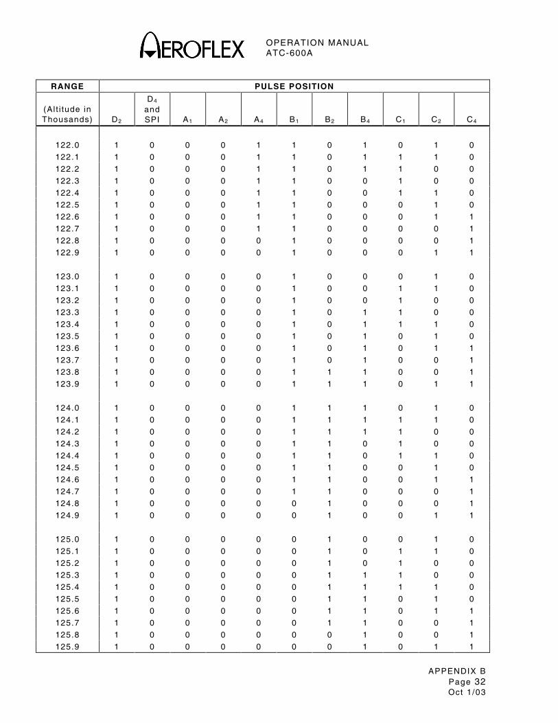
OPERATION MANUAL ATC-600A
APPENDIX B Page 32 Oct 1 /03
RANGE PULSE POSITION
(Al t i tude in Thousands)
D2
D4 and SPI
A1
A2
A4
B1
B2
B4
C1
C2
C4
122.0 1 0 0 0 1 1 0 1 0 1 0
122.1 1 0 0 0 1 1 0 1 1 1 0
122.2 1 0 0 0 1 1 0 1 1 0 0
122.3 1 0 0 0 1 1 0 0 1 0 0
122.4 1 0 0 0 1 1 0 0 1 1 0
122.5 1 0 0 0 1 1 0 0 0 1 0
122.6 1 0 0 0 1 1 0 0 0 1 1
122.7 1 0 0 0 1 1 0 0 0 0 1
122.8 1 0 0 0 0 1 0 0 0 0 1
122.9 1 0 0 0 0 1 0 0 0 1 1
123.0 1 0 0 0 0 1 0 0 0 1 0
123.1 1 0 0 0 0 1 0 0 1 1 0
123.2 1 0 0 0 0 1 0 0 1 0 0
123.3 1 0 0 0 0 1 0 1 1 0 0
123.4 1 0 0 0 0 1 0 1 1 1 0
123.5 1 0 0 0 0 1 0 1 0 1 0
123.6 1 0 0 0 0 1 0 1 0 1 1
123.7 1 0 0 0 0 1 0 1 0 0 1
123.8 1 0 0 0 0 1 1 1 0 0 1
123.9 1 0 0 0 0 1 1 1 0 1 1
124.0 1 0 0 0 0 1 1 1 0 1 0
124.1 1 0 0 0 0 1 1 1 1 1 0
124.2 1 0 0 0 0 1 1 1 1 0 0
124.3 1 0 0 0 0 1 1 0 1 0 0
124.4 1 0 0 0 0 1 1 0 1 1 0
124.5 1 0 0 0 0 1 1 0 0 1 0
124.6 1 0 0 0 0 1 1 0 0 1 1
124.7 1 0 0 0 0 1 1 0 0 0 1
124.8 1 0 0 0 0 0 1 0 0 0 1
124.9 1 0 0 0 0 0 1 0 0 1 1
125.0 1 0 0 0 0 0 1 0 0 1 0
125.1 1 0 0 0 0 0 1 0 1 1 0
125.2 1 0 0 0 0 0 1 0 1 0 0
125.3 1 0 0 0 0 0 1 1 1 0 0
125.4 1 0 0 0 0 0 1 1 1 1 0
125.5 1 0 0 0 0 0 1 1 0 1 0
125.6 1 0 0 0 0 0 1 1 0 1 1
125.7 1 0 0 0 0 0 1 1 0 0 1
125.8 1 0 0 0 0 0 0 1 0 0 1
125.9 1 0 0 0 0 0 0 1 0 1 1
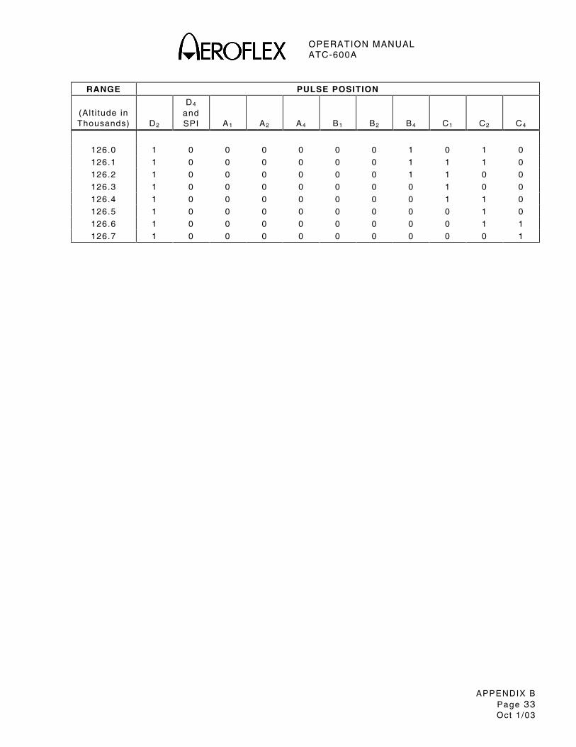
OPERATION MANUAL ATC-600A
APPENDIX B Page 33 Oct 1 /03
RANGE PULSE POSITION
(Al t i tude in Thousands)
D2
D4 and SPI
A1
A2
A4
B1
B2
B4
C1
C2
C4
126.0 1 0 0 0 0 0 0 1 0 1 0
126.1 1 0 0 0 0 0 0 1 1 1 0
126.2 1 0 0 0 0 0 0 1 1 0 0
126.3 1 0 0 0 0 0 0 0 1 0 0
126.4 1 0 0 0 0 0 0 0 1 1 0
126.5 1 0 0 0 0 0 0 0 0 1 0
126.6 1 0 0 0 0 0 0 0 0 1 1
126.7 1 0 0 0 0 0 0 0 0 0 1

OPERATION MANUAL ATC-600A
APPENDIX B Page 34 Oct 1 /03
THIS PAGE INTENTIONALLY LEFT BLANK.
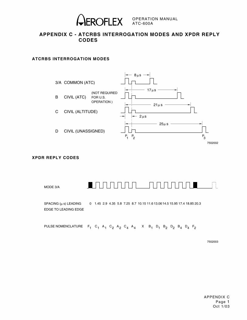
OPERATION MANUAL ATC-600A
APPENDIX C Page 1
Oct 1 /03
APPENDIX C - ATCRBS INTERROGATION MODES AND XPDR REPLY CODES
ATCRBS INTERROGATION MODES
3/A
B
C
D
COMMON (ATC)
CIVIL (ATC)
CIVIL (ALTITUDE)
CIVIL (UNASSIGNED)
FOR U.S.(NOT REQUIRED
OPERATION )
P1 2
P P3
25 s
21 s
17 s
8 s
7502002
2 s
µ
µ
µ
µ
µ
XPDR REPLY CODES
7502003
PULSE NOMENCLATURE
SPACING ( s) LEADING
EDGE TO LEADING EDGE
MODE 3/A
µ
F1 1C A 1 C2 A 2 C4 A 4 B1X 1D B2 D2 B4 D4 F2
0 1.45 2.9 4.35 5.8 7.25 8.7 10.15 11.6 13.06 14.5 15.95 17.4 18.85 20.3

OPERATION MANUAL ATC-600A
APPENDIX C Page 2
Oct 1 /03
THIS PAGE INTENTIONALLY LEFT BLANK.
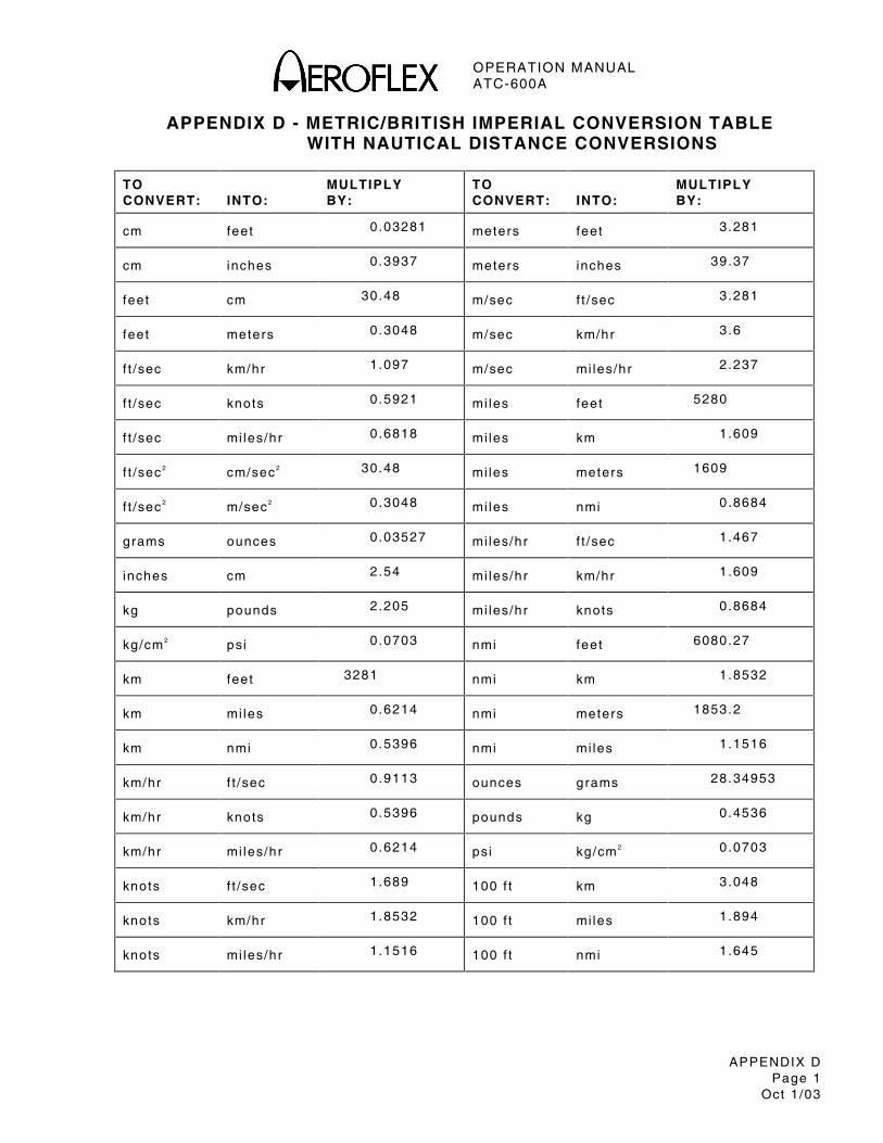
OPERATION MANUAL ATC-600A
APPENDIX D Page 1
Oct 1 /03
APPENDIX D - METRIC/BRITISH IMPERIAL CONVERSION TABLE WITH NAUTICAL DISTANCE CONVERSIONS
TO CONVERT:
INTO:
MULTIPLY BY:
TO CONVERT:
INTO:
MULTIPLY BY:
cm feet 0 .03281 meters feet 3 .281
cm inches 0.3937 meters inches 39.37
feet cm 30.48 m/sec f t /sec 3.281
feet meters 0.3048 m/sec km/hr 3 .6
f t /sec km/hr 1 .097 m/sec mi les/hr 2 .237
f t /sec knots 0.5921 mi les feet 5280
f t /sec mi les/hr 0 .6818 mi les km 1.609
f t /sec2 cm/sec2 30.48 mi les meters 1609
f t /sec2 m/sec2 0 .3048 mi les nmi 0 .8684
grams ounces 0.03527 mi les/hr f t /sec 1.467
inches cm 2.54 mi les/hr km/hr 1 .609
kg pounds 2.205 mi les/hr knots 0.8684
kg/cm2 psi 0 .0703 nmi feet 6080.27
km feet 3281 nmi km 1.8532
km mi les 0.6214 nmi meters 1853.2
km nmi 0.5396 nmi mi les 1.1516
km/hr f t /sec 0.9113 ounces grams 28.34953
km/hr knots 0.5396 pounds kg 0.4536
km/hr mi les/hr 0 .6214 psi kg/cm2 0.0703
knots f t /sec 1.689 100 f t km 3.048
knots km/hr 1 .8532 100 f t mi les 1.894
knots mi les/hr 1 .1516 100 f t nmi 1 .645

OPERATION MANUAL ATC-600A
APPENDIX D Page 2
Oct 1 /03
THIS PAGE INTENTIONALLY LEFT BLANK.
OPERATION MANUAL ATC-600A
APPENDIX E Page 1
Oct 1 /03
APPENDIX E - ABBREVIATIONS
A
A Ampere AC, ac Al ternat ing Current AH Ampere Hour ALT Al t imeter
B
BAT Bat tery
C
cm Cent imeter cw Clockwise ccw Counterclockwise
D
DC, dc Di rect Current dB Decibel dBm Decibe l above one Mi l l iwat t DME Distance Measur ing Equipment
F
FREQ Frequency f t Feet
G
GND Ground
H
HI High hr Hour Hz Hertz
I
IDENT Ident i f icat ion ILS Inst rument Landing System IN, in Input in Inch I /O Input /Output
K
kg Ki logram kΩ K i lohm kW Ki lowat t
L
lbs Pounds LO Local Osci l la tor
M
m Meter MHz Megaher tz MTL Min imum Tr igger Level MTR Meter
N
NiCad Nickel Cadmium NM, nmi Naut ica l Mi les
O
OUT, out Output
P
para Paragraph pps Pulses per Second PRF Pulse Repet i t ion Frequency psi Pounds per Square Inch PWR Power
R
RF Radio Frequency rms Root Mean Square RPLY Reply
S
STDBY Standby sec Second
U
UUT Uni t Under Test
V
V Vol t VAC Vol ts Al ternat ing Current Vdc Vol ts Di rect Current
W
W Watt
X
XPDR Transponder

OPERATION MANUAL ATC-600A
APPENDIX E Page 2
Oct 1 /03
THIS PAGE INTENTIONALLY LEFT BLANK.
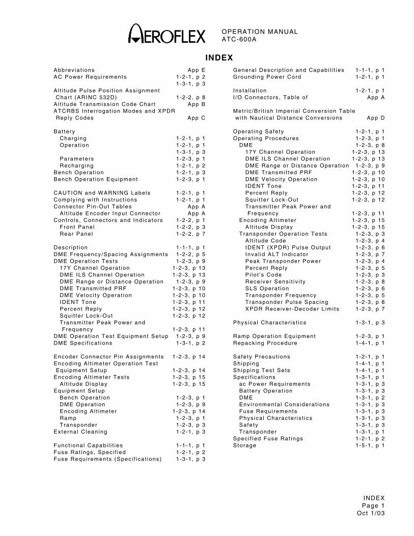
OPERATION MANUAL ATC-600A
INDEX Page 1
Oct 1 /03
INDEXAbbrev ia t ions App E AC Power Requi rements 1-2-1 , p 2 1 -3-1 , p 3 A l t i t ude Pu lse Pos i t ion Ass ignment Char t (ARINC 532D) 1-2-2 , p 8 A l t i t ude Transmiss ion Code Char t App B ATCRBS In ter rogat ion Modes and XPDR Reply Codes App C Bat tery Charg ing 1-2-1 , p 1 Operat ion 1-2-1 , p 1 1 -3-1 , p 3 Parameters 1-2-3 , p 1 Recharg ing 1-2-1 , p 2 Bench Operat ion 1-2-1 , p 3 Bench Operat ion Equipment 1-2-3 , p 1 CAUTION and WARNING Labels 1-2-1 , p 1 Comply ing wi th Ins t ruc t ions 1-2-1 , p 1 Connec tor P in-Out Tab les App A A l t i t ude Encoder Input Connec tor App A Cont ro ls , Connec tors and Ind icators 1-2-2 , p 1 Front Pane l 1-2-2 , p 3 Rear Panel 1-2-2 , p 7 Desc r ip t ion 1-1-1 , p 1 DME Frequency /Spac ing Ass ignments 1-2-2 , p 5 DME Operat ion Tes ts 1-2-3 , p 9 17Y Channel Operat ion 1-2-3 , p 13 DME ILS Channel Operat ion 1-2-3 , p 13 DME Range or D is tance Operat ion 1-2-3 , p 9 DME Transmi t ted PRF 1-2-3 , p 10 DME Veloc i t y Operat ion 1-2-3 , p 10 IDENT Tone 1-2-3 , p 11 Percent Reply 1-2-3 , p 12 Squ i t te r Lock -Out 1-2-3 , p 12 Transmi t ter Peak Power and Frequency 1-2-3 , p 11 DME Operat ion Tes t Equ ipment Setup 1-2-3 , p 9 DME Spec i f i ca t ions 1-3-1 , p 2 Encoder Connec tor P in Ass ignments 1-2-3 , p 14 Encod ing A l t imeter Operat ion Tes t Equ ipment Setup 1-2-3 , p 14 Encod ing A l t imeter Tes ts 1-2-3 , p 15 A l t i t ude Disp lay 1-2-3 , p 15 Equipment Setup Bench Operat ion 1-2-3 , p 1 DME Operat ion 1-2-3 , p 9 Encod ing A l t imeter 1-2-3 , p 14 Ramp 1-2-3 , p 1 Transponder 1-2-3 , p 3 Ex terna l C lean ing 1-2-1 , p 3 Func t iona l Capab i l i t ies 1-1-1 , p 1 Fuse Rat ings , Spec i f ied 1-2-1 , p 2 Fuse Requi rements (Spec i f i ca t ions ) 1-3-1 , p 3
Genera l Desc r ip t ion and Capabi l i t ies 1-1-1 , p 1 Grounding Power Cord 1-2-1 , p 1 Ins ta l la t ion 1-2-1 , p 1 I /O Connec tors , Tab le o f App A Met r i c /Br i t i sh Imper ia l Convers ion Tab le w i th Naut ica l D is tance Convers ions App D Operat ing Safe ty 1-2-1 , p 1 Operat ing Procedures 1-2-3 , p 1 DME 1-2-3 , p 8 17Y Channel Operat ion 1-2-3 , p 13 DME ILS Channel Operat ion 1-2-3 , p 13 DME Range or D is tance Operat ion 1-2-3 , p 9 DME Transmi t ted PRF 1-2-3 , p 10 DME Veloc i t y Operat ion 1-2-3 , p 10 IDENT Tone 1-2-3 , p 11 Percent Reply 1-2-3 , p 12 Squ i t te r Lock -Out 1-2-3 , p 12 Transmi t ter Peak Power and Frequency 1-2-3 , p 11 Encod ing A l t imeter 1-2-3 , p 15 A l t i t ude Disp lay 1-2-3 , p 15 Transponder Operat ion Tes ts 1-2-3 , p 3 A l t i t ude Code 1-2-3 , p 4 IDENT (XPDR) Pu lse Output 1-2-3 , p 6 Inva l id ALT Ind icator 1-2-3 , p 7 Peak Transponder Power 1-2-3 , p 4 Percent Reply 1-2-3 , p 5 P i lo t ’ s Code 1-2-3 , p 3 Rece iver Sens i t i v i t y 1-2-3 , p 8 SLS Operat ion 1-2-3 , p 6 Transponder Frequency 1-2-3 , p 5 Transponder Pu lse Spac ing 1-2-3 , p 8 XPDR Rece iver -Decoder L im i ts 1-2-3 , p 7 Phys ica l Charac ter is t i cs 1-3-1 , p 3 Ramp Operat ion Equipment 1-2-3 , p 1 Repack ing Procedure 1-4-1 , p 1 Safe ty Precaut ions 1-2-1 , p 1 Sh ipp ing 1-4-1 , p 1 Sh ipp ing Tes t Sets 1-4-1 , p 1 Spec i f i ca t ions 1-3-1 , p 1 ac Power Requi rements 1-3-1 , p 3 Bat tery Operat ion 1-3-1 , p 3 DME 1-3-1 , p 2 Env i ronmenta l Cons idera t ions 1-3-1 , p 3 Fuse Requi rements 1-3-1 , p 3 Phys ica l Charac ter is t i cs 1-3-1 , p 3 Safe ty 1-3-1 , p 3 Transponder 1-3-1 , p 1 Spec i f ied Fuse Rat ings 1-2-1 , p 2 S torage 1-5-1 , p 1
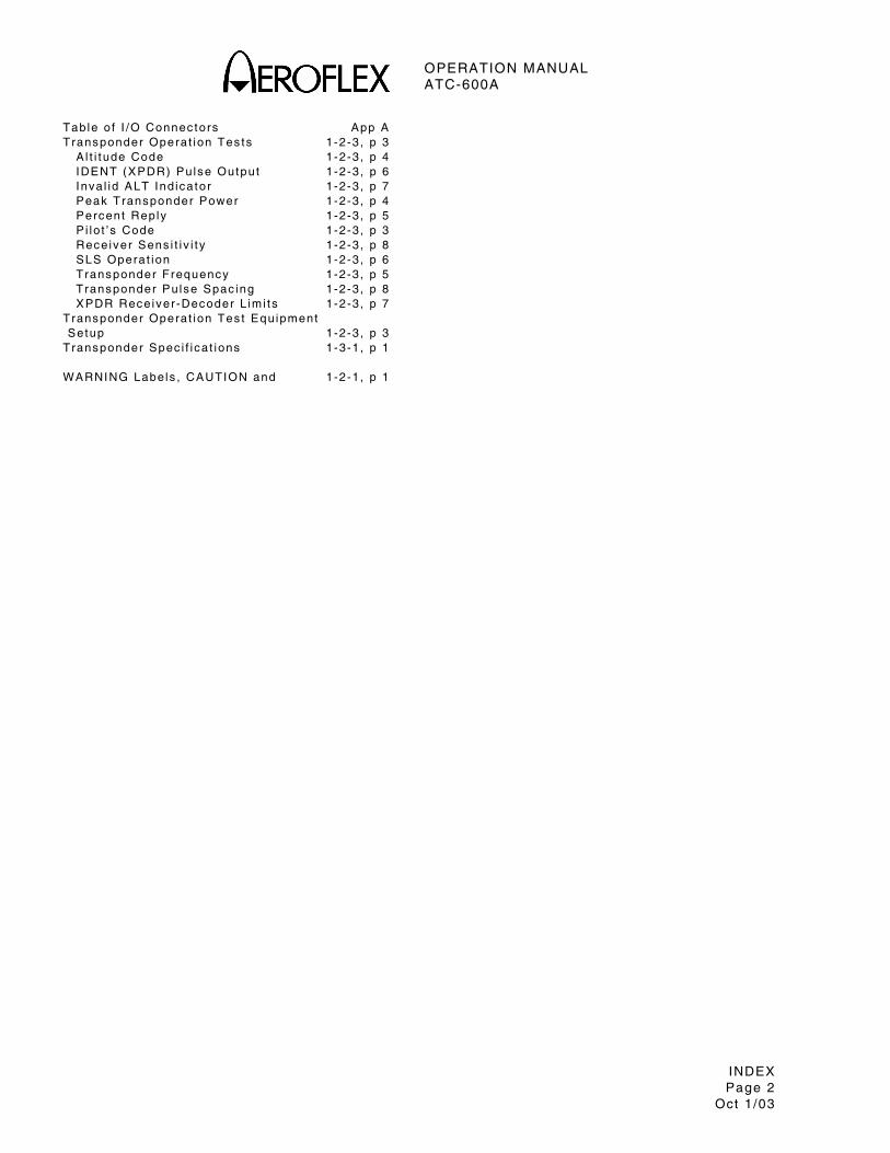
OPERATION MANUAL ATC-600A
INDEX Page 2
Oct 1 /03
Tab le o f I /O Connec tors App A Transponder Operat ion Tes ts 1-2-3 , p 3 A l t i t ude Code 1-2-3 , p 4 IDENT (XPDR) Pu lse Output 1-2-3 , p 6 Inva l id ALT Ind icator 1-2-3 , p 7 Peak Transponder Power 1-2-3 , p 4 Percent Reply 1-2-3 , p 5 P i lo t ’ s Code 1-2-3 , p 3 Rece iver Sens i t i v i t y 1-2-3 , p 8 SLS Operat ion 1-2-3 , p 6 Transponder Frequency 1-2-3 , p 5 Transponder Pu lse Spac ing 1-2-3 , p 8 XPDR Rece iver -Decoder L im i ts 1-2-3 , p 7 Transponder Operat ion Tes t Equ ipment Setup 1-2-3 , p 3 Transponder Spec i f i ca t ions 1-3-1 , p 1 WARNING Labels , CAUTION and 1-2-1 , p 1

Our passion for performance is defined by threeattributes represented by these three icons:
solution-minded, performance-driven, customer-focused.
As we are always seeking to improve our products, the information in
this document gives only a general indication of the product capacity,
performance and suitability, none of which shall form part of any
contract. We reserve the right to make design changes without notice.
CHINA Tel: [+86] (21) 6282 8001 Fax: [+86] (21) 6282 8002
FRANCE Tel: [+33] 1 60 79 96 00 Fax: [+33] 1 60 0177 69 22
HONG KONG Tel: [+852] 2832 7988 Fax: [+852] 2834 5364
SCANDINAVIA Tel: [+45] 9614 0045 Fax: [+45] 9614 0047
SPAIN Tel: [+34] (91) 640 11 34 Fax: [+34] (91) 640 06 40
UNITED KINGDOM Tel: [+44] (0) 1438 742200 Fax: [+44] (0) 1438 7276
Toll Free: 0800 282388 (UK only)
USA Tel: [+1] (316) 522 4981 Fax: [+1] (316) 522 1360
Toll Free: 800 835 2352 (US only)


![Data-sheet electronic braking system VersiBrake [40 - 600A] · Elektronic Braking System VB [40 — 600A] Electronic Braking System VersiBrake [40 - 600A] Typical Applications: ventilators](https://img.pdfslide.net/doc/110x75/5e156b092a3f3c6e3c58bd78/data-sheet-electronic-braking-system-versibrake-40-600a-elektronic-braking-system.jpg)