Embed Size (px)
Citation preview
Rapid fabrication strategies for primary and secondary mirrors atSteward Observatory Mirror Laboratory
D. Anderson, H. Martin, J. Burge, D. Ketelsen, S. WestSteward Observatory Mirror Laboratory
University of ArizonaTucson, Arizona
ABSTRACT
The pursuit of economical fabrication of large (8 m) fast ( < f/2), astronomical optics has led to the developmentof efficient fabrication and testing methods at the Mirror Lab. These methods rely on a mix of advanced technologyblended with some traditional practices. Two fabrication strategies have been developed, one or primary mirrorsand one for secondary mirrors. Both of these plans rely heavily on the use of the stressed lap both as a grinder aswell as for polishing. For secondary fabrication novel methods of testing the convex, severely aspheric mirrorsare used.
1. INTRODUCTION
Eight meter class astronomical optics have been a dream of many astronomers since the days of Ritchey andHale1. Sixty years later they are fmally becoming realities in a number of projects from various organizations.Fabricating the optics to the required accuracy has driven the fabrication community to adopt novel and powerfultechniques to keep the costs of fabrication non-astronomical. The competition between groups has resulted in adiverse array of clever methods. Over the last decade SOML has developed a set of fabrication strategies for verylarge primary and secondary mirrors, the largest currently slated to be the 8.4 m, f/i. 14 primaries for the LargeBinocular Telescope (LBT). Not only does the sheer size of these mirrors make them difficult to fabricate but alsothe very short focal ratios requiring very severe aspheric departures. Requirements for the wavefront quality haveonly become tighter as the seeing quality is better at many sites. As stepping stones towards fabricating the LBTmirrors the Mirror Lab has fabricated a number of large, fast primaries. These include the 1.8 m, f/i VATTprimary, the 3.5 m f/1.5 SOR primary, and the 3.5 m f/1.75 ARC and WIYN primaries. Currently, the Lab isworking on a 6.5 m f/i .25 primary for the MMT and is anticipating a successful casting of its twin for the MagellanTelescope.
Concurrent with the development of primary mirror fabrication methods the Lab is developing new methodsfor fabricating the very challenging (and numerous) secondary mirrors. Like the primary mirrors, the size andamount of asphericity in these mirrors call for new approaches to testing and fabrication. We have recentlydeveloped a new technique for testing these mirrors that will make the fabrication more efficient and accurate.
2. MIRROR BLANK FABRICATION
Primary mirror fabrication begins with the procurement of the blank. The Mirror Lab has developed thecapability of making the blanks in the form of a borosilicate honeycomb mirror substrate as shown in Figure 1.All the mirrors mentioned above are of this form. The mirrors are spun-cast to introduce into the blank the requiredinitial curvature. This initial step results in a very large savings in glass and time spent in producing the curvatures,especially at these very low f ratios. Typically, only 6 mm of glass need be removed from the front and rearsurfaces to bring them to final thickness.
O-8194-1494-8/94/$6.OO SPIE Vol. 2199 / 199

3. PRIMARY MIRROR FABRICATION STRATEGY
Experience gained in fabricating the 3 .5 m mirrors and the 1 .8 m f/i mirror has enabled us to converge on afabrication strategy that is very efficient as well as capable of producing very high quality surfaces. While somedetails of the plan are related specifically to borosilicate or honeycomb mirrors, the basic strategy can be appliedto any large optic.
The development of the strategy follows from the optical surface requirements for the mirrors. For theseground-based telescopes a structure function has been adopted that follows from wavefront propagation through theatmosphere.2 The structure function defines the required figure quality in terms of rms wavefront (or surface height)differences over a spectrum of spatial scales ranging from less than a centimeter up to the full aperture of themirror. In Figure 2 is a plot of the required structure function for the LBT mirrors. Like the atmosphericallydistorted wavefront, the mirror figure must be much more accurate at small scales than large scales. The limitingsmall scale accuracy requirement (5 am rms surface error) is set by the requirement that no more than 3 % of thelight at a wavelength of 350 nm be scattered outside the seeing disk.
200/SPIE Vol. 2199
1000
100
10
4,C)
4,4,
04)
In
separation (m)Figure 2. The structure function specification for the LBT primary mirror.
Figure 1. The borosilicate honycomb structure of the 6.5 m cast in the Mirror Lab's spinning furnace.
0.1 1

Given this form of the specification it is clear that it is important to produce a surface that is as smooth aspossible at small spatial scales where the spec is very tight. At large spatial scales the requirement is considerablyrelaxed which suggests fabrication methods that produce smooth surfaces but may have more difficulty with largescale errors. As will be seen from our results, with the methods that we employ, when the spec is achieved at smallscales the large scale errors are many times better than required. The strategy that has emerged from our workis shown schematically as:
Fixed diamond generate Stressed lap grind Stressed lap polish Small tool correction
asphere. Profilometry with loose abrasive. Visible interferometrywith LVDT on LOG. IR interferometry
It is vitally important in rapid fabrication that each process step avoid introducing errors that cannot be rapidlyremoved by subsequent steps. One key element of this is to properly support the optic throughout the process thatin a way closely duplicates the final support and does not imprint any errors during the polishing process. For thisreason a "polishing cell" for each mirror is constructed that duplicates the telescope cell support forces as closelyas possible. The mirror is installed on this support prior to work on the optical surface. This support is a passivehydraulic system of interconnected rolling diaphragm actuators delivering a support that duplicates the axial supportof the active supports in the telescope cell.
3.1 Fixed diamond generation.
The first step in the process is the removal of a nearly uniform thickness layer of glass from the surface toachieve final faceplate and backplate thickness while at the same time introducing the asphere. This is done withfixed diamond tools working on the Large Optical Generator (LOG).3 This machine can be rapidly configured foreither generating or grinding/polishing with either a passive or active lap. For generating, the machine is capableof generating up to 8.4 m aspheres to 10 microns rms.
Initial generating is performed with a coarse diamond cup wheel to remove about 6 mm of glass on the frontand backplates to bring them to the desired thickness. While the machine can remove up to 17 cubic inches of glassper minute we typically remove about 8 cubic inches per minute. Following the rough removal, two sizes of finediamond, 220 mesh and 600 mesh, in a resin bond cup wheel, are used to give the surface a smooth finish with lowsubsurface damage. While we have demonstrated that this surface can be directly polished the remaining figureerrors are large enough that lapping the surface with loose abrasive is much more efficient.
To monitor the figure during aspherization the surface is profiled in situ with an LVDT mounted on the LOGspindle. In this way errors due to wheel geometry and wheel wear as well as setup errors can be removed. Inaddition, azimuthal measurements can be made to check the functioning of the support and turntable. Correctionscan be made directly in the tool path profile to reduce the surface errors. The limitation on the figure quality atthis stage is largely the calibration accuracy of the machine.
3.2. Stressed lap grinding
Loose abrasive lapping of the surface, while not as rapid as generating with diamond, is much more easilycontrolled. Since a fine surface has already been achieved through fine diamond generating, removal of figureerrors is now the main concern. The lapping is accomplished with the stressed lap4'5, where the pitch layer is coatedwith a thin layer of zinc.
Use of the stressed lap grinder/polisher is the key element in the rapid figuring of the mirror. The basicstrategy of using the stressed lap is to use a tool that is large enough to smooth the surface rapidly but small enoughto be useful in correcting figure errors. The lap is actively deformed under computer control so that the lap alwaysclosely fits the aspheric shape of the mirror. This provides for rapid smoothing of already rough surfaces and, oncesmooth, does not introduce high frequency zonal errors common with passive laps. The lap that has been used forthe 3.5 m mirrors will also be used on the 6.5 m and 8.4 m mirrors. It is 1.5 m in diameter with a maximumpitch
SPIE Vol. 2199/201

surface 1.2 m in diameter. The lap, shown in cross section in Figure 3, is composed of a 1.5 m diameter, 50 mmthick plane parallel aluminum plate with a layer of nylon that is shaped to provide the minimum lap curvature.Actuators apply bending moments to the plate to provide a variable increase in curvature and other low orderdeformations. The nylon is faced with a layer of pitch for polishing and an additional thin layer (.4 mm) of zincfor grinding.
Load
II Nut
Trunnion
The stressed lap grinder can very rapidly remove the very high frequency errors created by the diamond wheelduring generation. In a matter of a few hours the surface is smooth enough to use JR phase measuringinterferometry to monitor the surface figure. In the case of the WIYN primary mirror, the f/1.75 asphere (170microns from best fit sphere) was completely ground in with the stressed lap grinder and loose abrasive. Bygradually increasing the amount of bending in the lap from no bending (when the mirror is spherical) to thatrequired by the full asphere, the asphericity was introduced in a very smooth fashion. The mirror was fullyaspherized in this way in less than five weeks work and 52 hours of machine time. The working size of the lapwas chosen at .8 m to efficiently introduce the asphere from the best fit sphere by working only on the center andedge and very little on the .7 zone. It is clear from Figure 4 how smooth this process was.
:12-:1r pijimj
Ip
(b)
Figure 5. In (a) is an JR interferogram of the WIYN mirror after 10 hours of grinding. In (b) is shown anJR interferogram at the end of grinding through the null lens.
The lap size was large enough to prevent the creation of high frequency radial zones but small enough to removeany mid-frequency zonal errors by the proper choice of the polishing stroke. The machine operates under computercontrol via control software where lap stroke parameters such as the rotational speeds of the lap and mirror, the
202 ISPIE Vol. 2199
Figure 3. Cross sectional view of the stressed lap.
(a)

extent of the stroke, and the stroke velocity are all controlled. These many degrees of freedom available in thedesign of a stroke gives wide latitude in the spatial extent of the wear. These degrees of freedom are illustratedin Figure 5. Polishing pressure can also be controlled dynamically to address non-axisymmetric figure errors, andthe system will soon include dynamic control of moments corresponding to pressure gradients across the lap.
Extents of stroke
(1), rL) Lap rotation rate
VL((, rL) Lap linear velocity
Effective misfitin the conic constant
Polishing time
Predictive software6 provides guidance on the utility of any stroke in removing radial errors prior to a polishingrun. Convergence can be very rapid with improvements in the figure by a factor of 2 per week. Shown in Figure6 are average radial profile plots of predicted and actual removal for a polishing run made during the polishing ofthe SOR 3.5 m primary. The removal, in this case, closely matches that predicted by the predictive software. Thepredictions made are not always so close to the actual removal. Other factors influencing the wear such as lapmisfit and the constantly changing condition of the pitch, result in less deterministic wear. There is still a largemeasure of empirical selection of stroke paramenters based on wear results from similar stroke parameters. TheLab is about to initiate a full set of controlled experiments on a 1.8 m mirror on a smaller polishing machine toimprove the predictions leading to even more rapid convergence.
0.
0.06
0.02
-0.02
-0.06
—0.10CD
—0.14ECl,c -0.18'
-0.22
-0.26
-0.30
13:39 Air Force 3.5 m F/1.5 Simulated removal
11— 2—1991 082091— — Measured difference
Figure 6. Average radial profile plots comparing actual removal to the predicted removal during a polishingrun with the stressed lap.
SPIE Vol. 2199/203
r1, r0
T
Figure 5. The degrees ot Ireedom in the polishing stroke using the stressed lap.
Normalized radial distance

When about 20 microns of glass have been removed from the surface and figure errors are below 1 micron rmspolishing commences. We try to improve the surface figure even during the initial polishing when the primary goalis to completely polish the surface. By combining the polish-out stage with some figuring we are able to convergerapidly to a surface that is about .25microns mis and polished out.
Phase measuring JR interferometry guides the process through the grinding stage and into the initial polishingstage. A germanium null lens provides correction for the asphericity. It is critical for rapid convergence to finalfigure that this null lens be made as accurately as possible. Computer-generated holograms will be used to verifythe accuracy of both the JR null lens and the visible null lens.1 By certifying both null lenses with the hologramany errors detected in their construction can be mapped and removed from the data assuring an accurate test.
3.3. Final figuring.
At this point we switch to visible phase measuring interferometry through a null lens and proceed with the finalfiguring with the stressed lap. The phase map of the surface provides us with a very detailed surface error map.Three types of surface error are addressed in different ways. The surface can be thought of as a sum of purelyradial errors, low order azimuthal errors (such as astigmatism) and high frequency azimuthal errors (small bumpsand holes). Low order azimuthal errors are addressed by active control of the pressure the lap exerts on the glassbecause the polishing rate varies approximately linearly with the lap pressure. A "pressure map" is generated fromthe phase data and the polishing stroke parameters, and is used to vary the pressure during the polishing run. Thelarge scale azimuthal errors are very quickly controlled in this way.
Azimuthal errors on the order of the size of the lap are not readily removed by pressure variations. There isa great deal of natural smoothing that occurs but some degree of this type of error remains. There are two wayswe can remove them. The first is to provide a pressure gradient across the lap that can better resolve the polishingforces and hence the removal. This is done by using three tilt actuators attached to the lap that can apply momentsto the lap creating pressure gradients across it. This can provide more localized polishing and better removal ofthe azimuthal errors and radial errors as well. The second method is to use a small passive tool (about 200 mmdiameter) on an orbital spindle attached to the main spindle, and under constant pressure simply use increased dwelltime over the high areas to rapidly converge. While small tool polishing is efficient in removing this type of errorwe use it sparingly since it does tend to introduce very high frequency errors. Fortunately, the stressed lap is veryefficient at removing that type of error so we alternate between them when using the small lap.
The remaining radial errors are removed by the selection of the proper stroke parameters. High frequencyerrors are smoothed by the well fitting lap leaving only mid to low frequency radial errors. Pressure gradientsacross the lap can reduce the spatial frequency of the removal as can simply making the lap smaller in size.
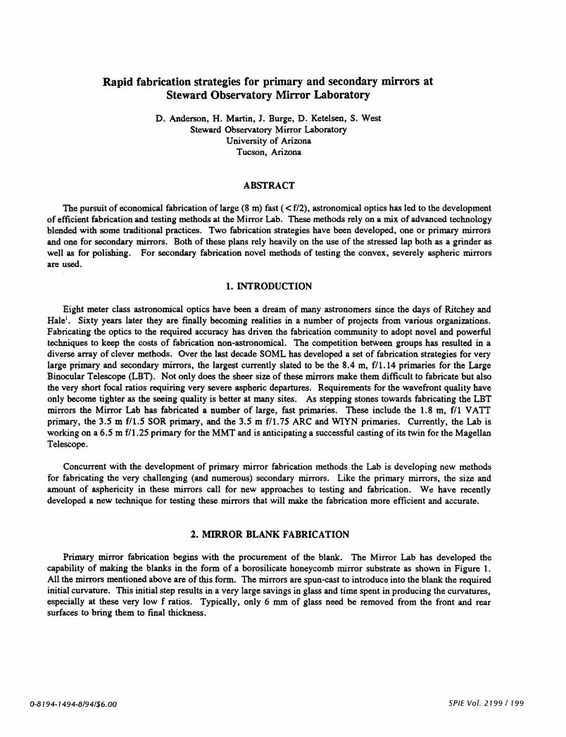
One of the difficulties faced with any lightweight honeycomb or cellular mirror is the "print-through" ofthe cellular structure of the mirror into the surface figure during polishing. The problem originates when the lappasses over the unsupported area between the ribs which deflect under the lap pressure thus reducing the polishingforce and the wear. After the lap passes by, the core areas spring back and appear as bumps in the surface. InFigure 7 is a phase map of the WIYN mirror during the initial stage of polishing when the polishing pressures usedwere high (.5 psi). The bumpy pattern on the surface is the print-through of the cellular structure. Theaccompanying contour plot is of the "average cell" showing the shape and magnitude of the average print-through.To reduce this effect the mirror is internally pressurized with air during polishing. The pressure is adjusted to bethe same as the average lap polishing pressure, which supplies just enough force to balance the lap pressure toproduce near zero deflection of the surface. In Figure 8 is shown a phase map of the finished WIYN mirror anda plot of the average cell. The stressed lap has removed the existing print-through and reduced the remaining errorby a factor of 7. The remaining print-through at 6 nm p-v is negligible with respect to the structure functionspecification. The pressurization of the mirror does cause some low order bending of the mirror (about .6 wavesof astigmatism) but the stressed-lap is small enough to ride over the low order error without imprinting it into thesurface. When the pressure is turned off for testing the error vanishes.
204 ISPIE Vol. 2199
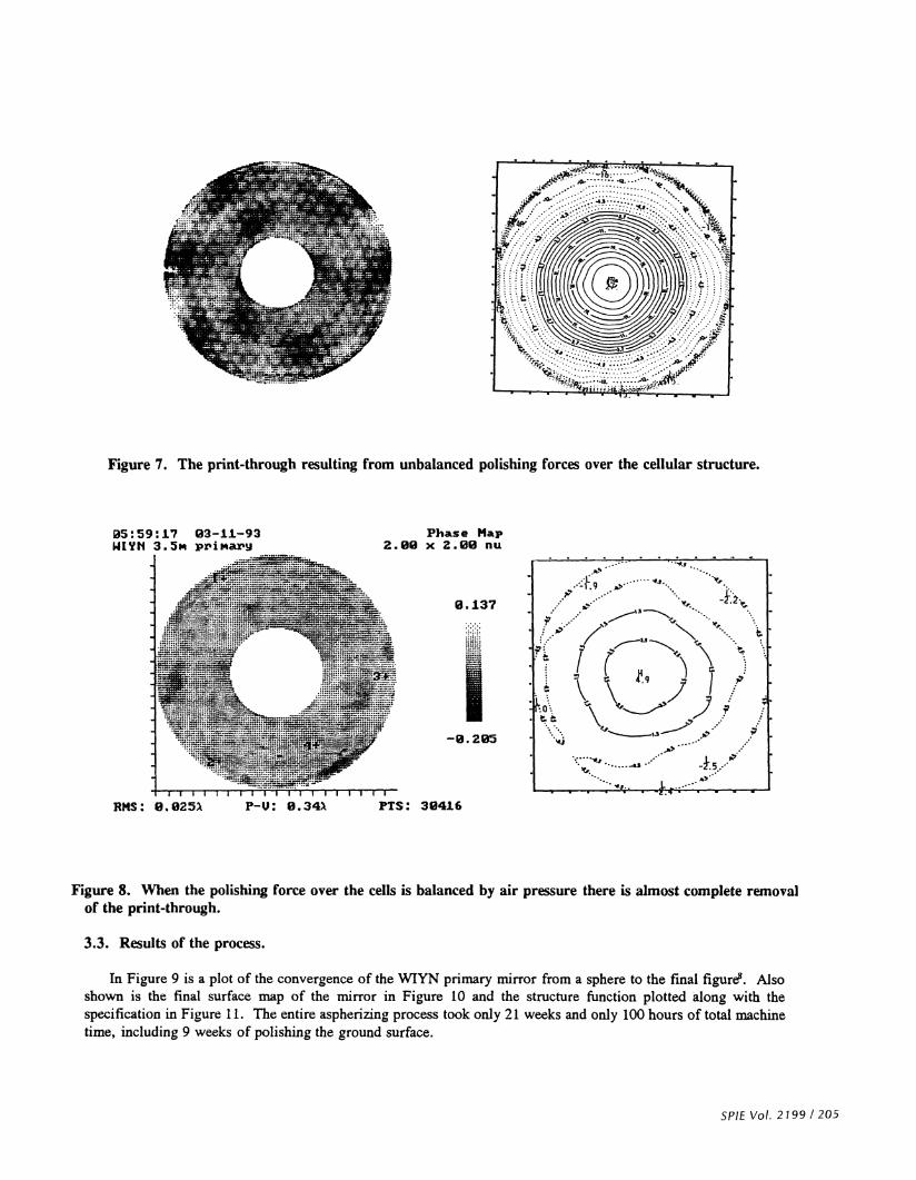
Figure 7. The print-through resulting from unbalanced polishing forces over the cellular structure.
5:59:I7 p3—11—93WITh 3.5M PPiN3PY
=_P_ ..; = -.
;;E ; - .. =;::::JL_ :E JE iiF.= .r ¼EL:fi=.=
:;::::;::::::::::::::;:::::j ..:::;:.•:::.
Er:: _::•:;-:--:-_J rt::: 4:i7: 9
.i._= — ::: •:;-.:z.... -.
1__lr1wI I u1FIIIJ [1
Rils: O.025k P-U: B.34 PTS: 3416
Figure 8. When the polishing force over the cells is balanced by air pressure there is almost complete removalof the print4hrough.
3.3. Results of the process.
In Figure 9 is a plot of the convergence of the WIYN primary mirror from a sphere to the final figure. Alsoshown is the final surface map of the mirror in Figure 10 and the structure function plotted along with thespecification in Figure 11. The entire aspherizing process took only 21 weeks and only 100 hours of total machinetime, including 9 weeks of polishing the ground surface.
SPIE Vol. 2199/205
Phase Map2.00 x 2.00 nu
0.137
I—0.205

100
L.2L.a,a,U
U)a,
0.01
weeks
Figure 9. The convergence to final figure for the WIYN primary.
Figure 10. The final phase map of the WIYN primary mirror over the clear aperture with a small amountof residual astigmatism removed.
206 ISPIE Vol. 2199
0 2 4 6 8 10 12 14 16 18 20 22
Phase Map2.ø x 2.00 flu05:59:1? 03-11—93ode\wiyn\vis\ 6TzB --
————I—I-I I 1111111W I I I liiiEMS: 15.9nM P-U: 215.?nM PTS: 30412
86.207
I—129. 464

EC)
0,C)C)0)L0)
-C)
C)0s-.
0)
C',
U)
E
For future mirrors beginning with the 6.5 m MMT primary we will have the advantage of using the results ofthe polishing experiments to improve convergence as well as guide the use of pressure gradients to control the wear.
4.1. Introduction.
4. SECONDARY MIRROR FABRICATION STRATEGY
Shown in Table 1 is a list of secondary mirrors currently scheduled to be made by the Mirror Lab. They arefor three projects: the MMT 6.5 m upgrade, the Sloan Digital Sky Survey Telescope, and the LBT. They rangein size from .6 m to 1.6 m, and though small, are numerous and highly asphenc so rapid fabrication methods arerequired.
Sloan MMTf/9
MMTf115
MMTf/5
LBT1/15
LBTf/4
Diameter (mm) 1143 996 620 1653 872 1170
Radius of curvature (mm) 7194 2806 1663 5022 -1890 3294
Conic constant -12.110 -1.749 -1.397 -2.640 -0.733 -3.236
Surface sag (mm) 22.7 44.2 28.9 68.0 -50.3 51.9
P-V asphere (microns) 108.4 152.2 87.7 304.0 -122.5 331.4
focal ratio 3.15 1.41 1.34 1.52 -1.08 1.41
Table 1. Secondary mirrors scheduled to be fabricated at the Mirror Lab.
SPIE Vol. 2199 / 207
WIYN 3711/93 clear1000
100
10
Figure 11. The structure
0.1 1
separation (m)funtion produce by the final WIYN surface.
The secondary mirror fabrication strategy is centered more fully around the stressed lap since there will be nofixed diamond generation of the asphere into the surface. The lapping in of the asphere on the WIYN primary wasso successful that we will use that as the aspherization method. Prior to aspherizing the mirrors they will first begenerated and ground to a radius of the best-fit sphere using a full sized tool in conventional fashion. Foraspherizing the mirrors the basic fabrication strategy is as follows:
Stress-lap grind asphere
with loose abrasive. Testin-situ with swing-armprofilometer.
Stress-lap polish asphere. Small tool correction
Test with full-sized holographic test plate
4.2. Stressed lap grinding of the asphere and swing-arm profilometry.
As described above, the stressed lap will be used as a grinding tool to lap in the asphere with loose abrasives.The shape of the lap will be varied with the amount of asphere as the process progresses so that the lap always fitsthe surface reasonably well. When the mirror is about 90 % aspherized polishing will commence.
Monitoring the aspherization with JR interferometry is difficult to do with convex aspheres of the sizes andspeeds required. Instead, we will use a swing-arm profilometer9"° to measure the mirrors in-situ on the polishingmachine. In swing-arm profilometry an arm holding an LVDT (as shown in Figure 12) is turned about an axis thatintersects the axis of the mirror at its center of curvature. When this is the case and the indicator passes throughthe center of the mirror, the indicator will measure the aspheric departure of the mirror. The tilted arm removesthe spherical component of the surface. This is the same principal used in curve generating spheres with diamondcup wheels. The profilometer will enable us to aspherize the mirror to about the same level as JR interferometry,around .3 microns rms. Unlike JR interferometry, however, only a radial profile is produced, not a full surfacemap. We expect that the azimuthal errors introduced by the stressed lap grinding will be small and could beremoved in final figuring.
4.3. Optical testing.
Figure 12. The swing arm profilometer.
Following aspherization and initial polishing of the surface, final figuring will be performed with the stressedlap guided by a novel test method--a holographic test plate.H Secondary mirrors have in the past been tested by
208 ISPIE Vol. 2199
\
PTVOT
S-AXIS S?4Z
PROSE

a variety of methods including the Hindle test, the Hindle shell test, through the rear surface with a null lens, withan aspheric test plate, and simply in the telescope. We will use a variation of the aspheric test plate method. Inthis method an aspheric test plate is made that is the exact opposite match of the surface of the secondary. Whenthe surfaces are brought into proximity and properly illuminated, fringes are formed that show the differencebetween the two surfaces. The better the test plate surface is made and measured independently the better thesecondary surface is known. This test has the advantage that there is only one precision surface required, thereference surface itself. The illumination and imaging optics can be of lower precision. Since the two surfaces arein close proximity to one another (a few millimeters separation) environmental errors from vibration and seeing arenegligible. Unfortunately, the reference surface is also an asphere and for these fast systems a very challengingtask to make and certify.
To get around this problem we use a spherical test plate, which is easy to make and certify, and on its surfacewrite a hologram that by diffraction provides the aspheric portion of the test beam. It is identical to a standard testplate configuration with the aspheric test plate surface replaced with a spherical surface with a hologram writtenon it. Alignment of the system is identical to that of an aspheric test plate and is guided by the fringes in a
straightforward way.
For rapid testing the holographic test plate is fixed in a mount adjacent to the secondary polishing machine asshown in Figure 13. To test the secondary mirrors as they will be used in the telescope, i.e. ,upside down, themirror will be polished in an invertible cell. The mirror and cell will be picked up off the polishing machine,inverted, and then set down on kinematic mounts just above the test plate. The test plate support ring will itselfbe supported at three points driven by PZT actuators to provide phase measuring capability. This test will providea rapid, full aperture measurement of the secondary that will be used to guide the figuring.
SPIE Vol. 2199 / 209
Figure 13. A flipping mechanism will deliver the inverted secondary into position for holographic testing.

3.3. Final figuring.
Final figuring willbe donewith the same lap control system as the primary mirrors. Stroke control will removethe radial errors and a combination of pressure variations and pressure gradients will remove the azimuthal errors.Small tool polishing will, again, be sparingly used as required to touch up the local errors, followed by stressedlapping. Given the relatively large size of these mirrors most of them will be cellular mirrors. Like the primaries,they will be pressurized during polishing to remove the print-through.
Since the mirrors will be tested full aperture to high resolution in the same support in which they will be used,we expect rapid convergence to final specification and very high quality images in the telescope.
REFERENCES
1. D.E. Oeterbrock, Pauper & Prince, The University of Arizona Press, 1993
2. J.M. Hill, "Optical Design, error budget, and specifications for the ColumbusProject Telescope." SPIE Vol. 1236, Advanced Technology Optical Telescopes IV,1990
3. D. Ketelsen, W. Davison, S. DeRigne, W. Kittrell, "A machine for completefabrication of 8—m class mirrors.", SPIE Vol. 2199, Advanced Technology OpticalTelescopes V, 1994 (in press).
4. H.M. Martin, D.S. Anderson, J.R.P. Angel, R.H. Nagel, S.C. West, and R.S.Young, "Progress in the Stressed lap polishing of a 1.8 m f/i mirror", AdvancedTechnology Optical Telescopes IV, SPIE Vol 1236, 1990.
5. H.M. Martin, D.S. Anderson, J.R.P. Angel, J.H. Burge, W.B. Davison, S.T.DeRigne, B.B. Hille, D.A. Ketelsen, W.C. Kittrell, R. McMillan, R.H. Magel, T.J.Trebiski, S.C. West, and R.S. Young, "Stressed lap polishing of 1.8-m f/i and3.5—m f/1.5 primary mirrors.", Proc. ESO Conference on Progress in Telescope andInstrumentation Tecnologies, ed. N.H. Ulrich, 1992.
6. J.H. Burge, "Computer simulation and optimization of stressed lappolishing.", OSA Annual Meeting Technical Digest, 1990.
7. J.H. Burge, "Certification of null correctors for primary mirrors," AdvancedOptical Manufacturing and Testing IV, SPIE Vol. 1994, 1993.
8. D. Anderson, J. Burge, D. Ketelsen, B. Martin, S. West, G. Poczulp, J.Richardson, W. Wong, "Fabrication and testing of the 3.5 m f/i.75 WIYM primarymirror," SPIE Vol 1994, Advanced Optical Manufacturing and Testing IV, 1993.
9. D.S. Anderson, R.E. Parks, L. Shao, "Versatile Prof ilometer for AsphericOptics", Optical Fabrication and Testing Technical Digest, Vol 11, 1990.
10. D.S. Anderson, "Swing—arm Prof ilometer", Mirror Lab Technical Memo,February, 1994.
11. J.H. Burge, D.S. Anderson, "Full-aperture interferometric test of convexsecondary mirrors using holographic test plates", Advanced Technology OpticalTelescopes V., SPIE Vol 2199, 1994 (in press).
210/SPIE Vol. 2199