Embed Size (px)
Citation preview
1
IDCOM, University of Edinburgh
April 2009© 2009 Copyright John Thompson
Rapid Prototyping of a Fixed-Throughput Sphere Decoder for MIMO Systems
Luis G. Barbero +, John S. Thompson and Xiang Wu
Institute for Digital CommunicationsUniversity of Edinburgh
+ Now with Queen’s University, Belfast
2
IDCOM, University of Edinburgh
April 2009© 2009 Copyright John Thompson
Overview of Presentation
• Introduction
• MIMO System
• Rapid Prototyping
• Sphere Decoder (SD)
• Fixed-Sphere Decoder (FSD)
• Diversity Order Analysis
• Ongoing Work and Conclusions
3
IDCOM, University of Edinburgh
April 2009© 2009 Copyright John Thompson
Introduction
• The use of multiple antennas at both transmitter and receiver (MIMO) significantly increases the capacity and spectral efficiency of wireless communication systems.
• The sphere decoder gives optimal maximum-likelihood performance in MIMO detection with reduced complexity compared to the maximum-likelihood detector.
• However, it has a variable complexity, depending on the noise level and the channel conditions, that hinders its integration into a complete communication system.
• A fixed-sphere decoder is proposed to achieve quasi-ML performance with fixed-complexity resulting in a fully-pipelined hardware implementation.
• Rapid prototyping is a design methodology where a system-level design, specified in a high-level description is quickly translated to a hardware implementation.
4
IDCOM, University of Edinburgh
April 2009© 2009 Copyright John Thompson
MIMO Wireless Systems
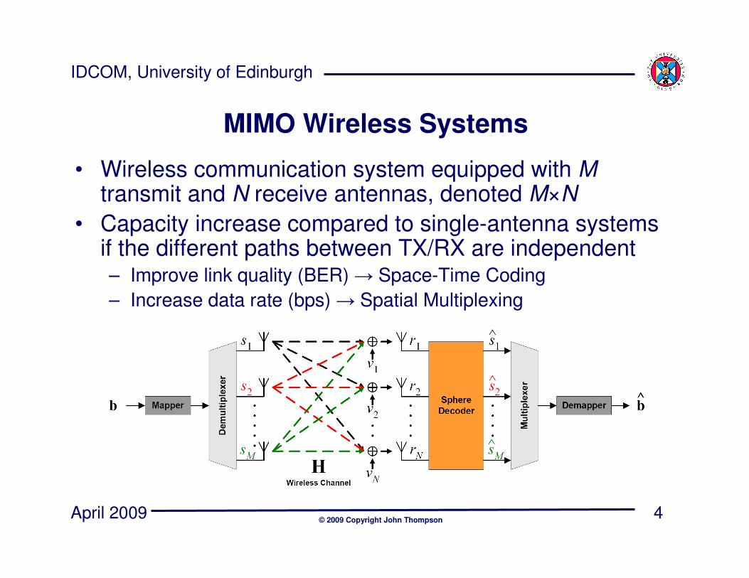
• Wireless communication system equipped with M transmit and N receive antennas, denoted M×N
• Capacity increase compared to single-antenna systems if the different paths between TX/RX are independent– Improve link quality (BER) → Space-Time Coding
– Increase data rate (bps) → Spatial Multiplexing
5
IDCOM, University of Edinburgh
April 2009© 2009 Copyright John Thompson
MIMO in Wireless Standards
• MIMO is now being integrated into many wireless standards
• Wireless Local Area Networks:
– IEEE 802.11N (Wifi)
• Cellular/Mobile Communications:
– IEEE 802.16 (Wimax)
– 3GPP Long Term Evolution (LTE)
6
IDCOM, University of Edinburgh
April 2009© 2009 Copyright John Thompson
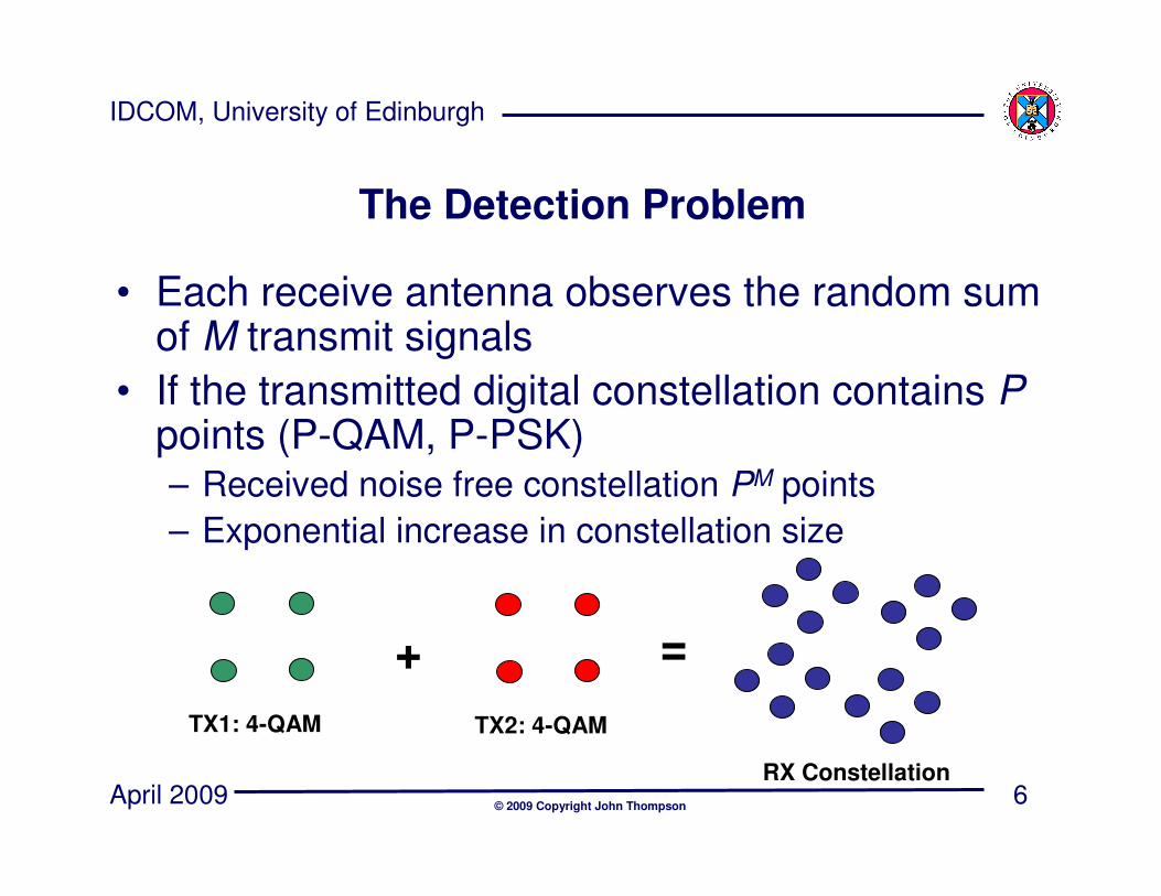
The Detection Problem
• Each receive antenna observes the random sum of M transmit signals
• If the transmitted digital constellation contains Ppoints (P-QAM, P-PSK)– Received noise free constellation PM points
– Exponential increase in constellation size
TX1: 4-QAM
RX Constellation
TX2: 4-QAM
+ =

7
IDCOM, University of Edinburgh
April 2009© 2009 Copyright John Thompson
• System equation is written as:
• The optimum detector compares the received signal vector r to every possible noise free constellation point Hs
• The optimum decision on the transmitted data is the closest constellation point in Euclidean distance
• Complexity of this approach is usually too high for complex constellations and large numbers of antennas → evaluate PM constellation points
Maximum Likelihood Decoding
vHsr += Receiver noise
Noise free signal
constellation
Received signal
8
IDCOM, University of Edinburgh
April 2009© 2009 Copyright John Thompson
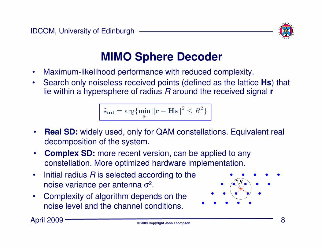
MIMO Sphere Decoder
• Maximum-likelihood performance with reduced complexity.
• Search only noiseless received points (defined as the lattice Hs) that lie within a hypersphere of radius R around the received signal r
• Real SD: widely used, only for QAM constellations. Equivalent real decomposition of the system.
• Complex SD: more recent version, can be applied to any constellation. More optimized hardware implementation.
• Initial radius R is selected according to the
noise variance per antenna σ2.
• Complexity of algorithm depends on the noise level and the channel conditions.
9
IDCOM, University of Edinburgh
April 2009© 2009 Copyright John Thompson
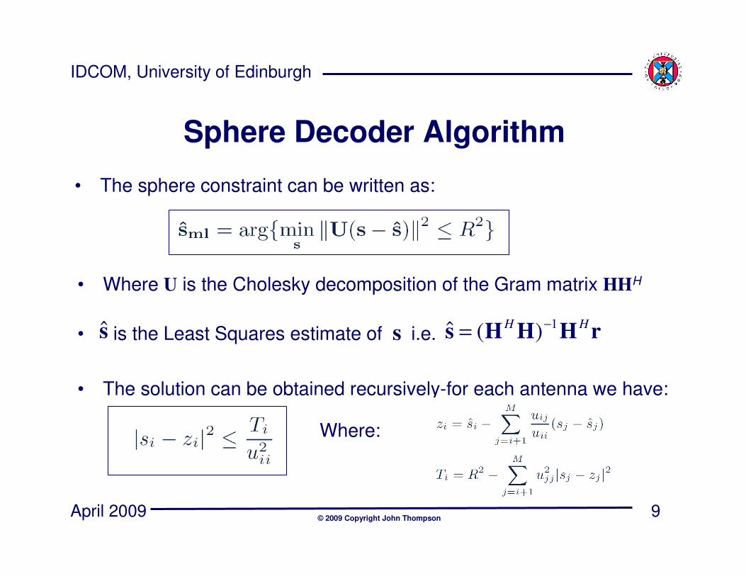
• Where U is the Cholesky decomposition of the Gram matrix HHH
• is the Least Squares estimate of s i.e.
• The solution can be obtained recursively-for each antenna we have:
Sphere Decoder Algorithm
• The sphere constraint can be written as:
rHHHsHH 1)(ˆ −
=s
Where:
10
IDCOM, University of Edinburgh
April 2009© 2009 Copyright John Thompson
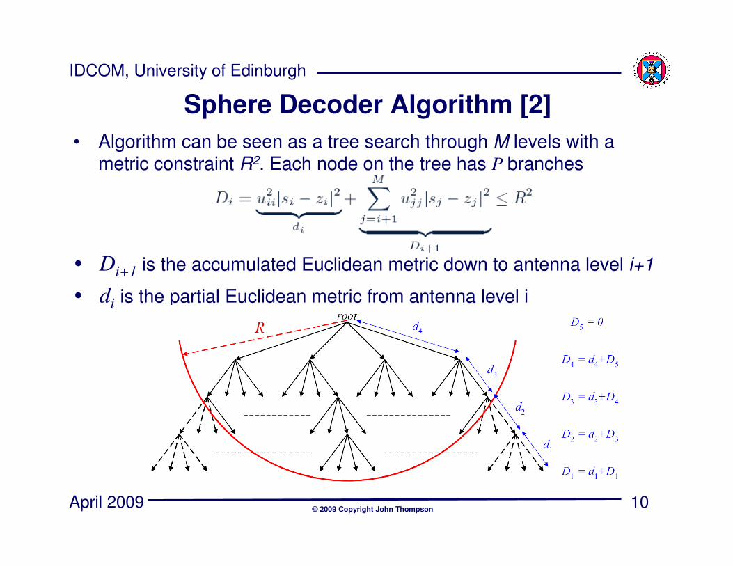
Sphere Decoder Algorithm [2]
• Algorithm can be seen as a tree search through M levels with a metric constraint R2. Each node on the tree has P branches
• Di+1 is the accumulated Euclidean metric down to antenna level i+1
• di is the partial Euclidean metric from antenna level i
11
IDCOM, University of Edinburgh
April 2009© 2009 Copyright John Thompson
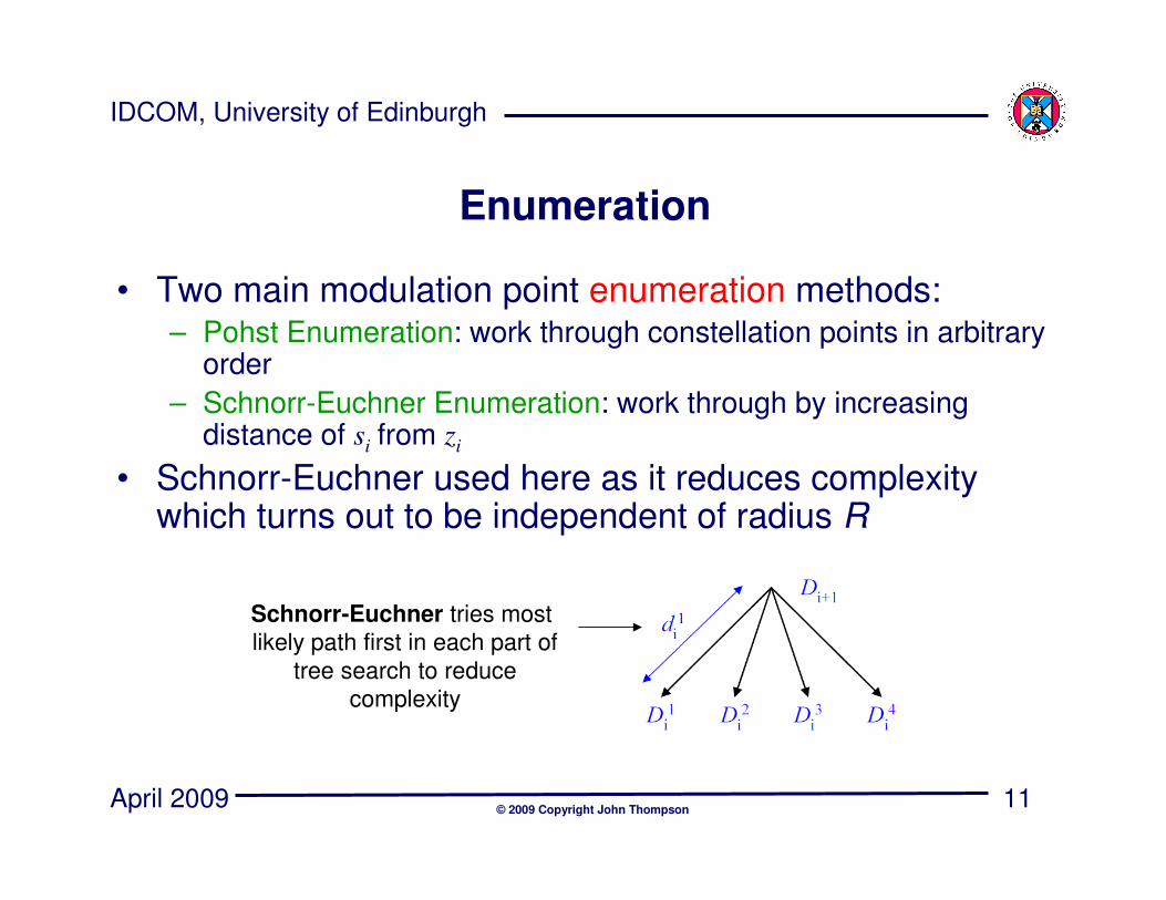
Enumeration
• Two main modulation point enumeration methods:– Pohst Enumeration: work through constellation points in arbitrary
order
– Schnorr-Euchner Enumeration: work through by increasing distance of si from zi
• Schnorr-Euchner used here as it reduces complexity which turns out to be independent of radius R
Schnorr-Euchner tries most
likely path first in each part of
tree search to reduce
complexity
12
IDCOM, University of Edinburgh
April 2009© 2009 Copyright John Thompson
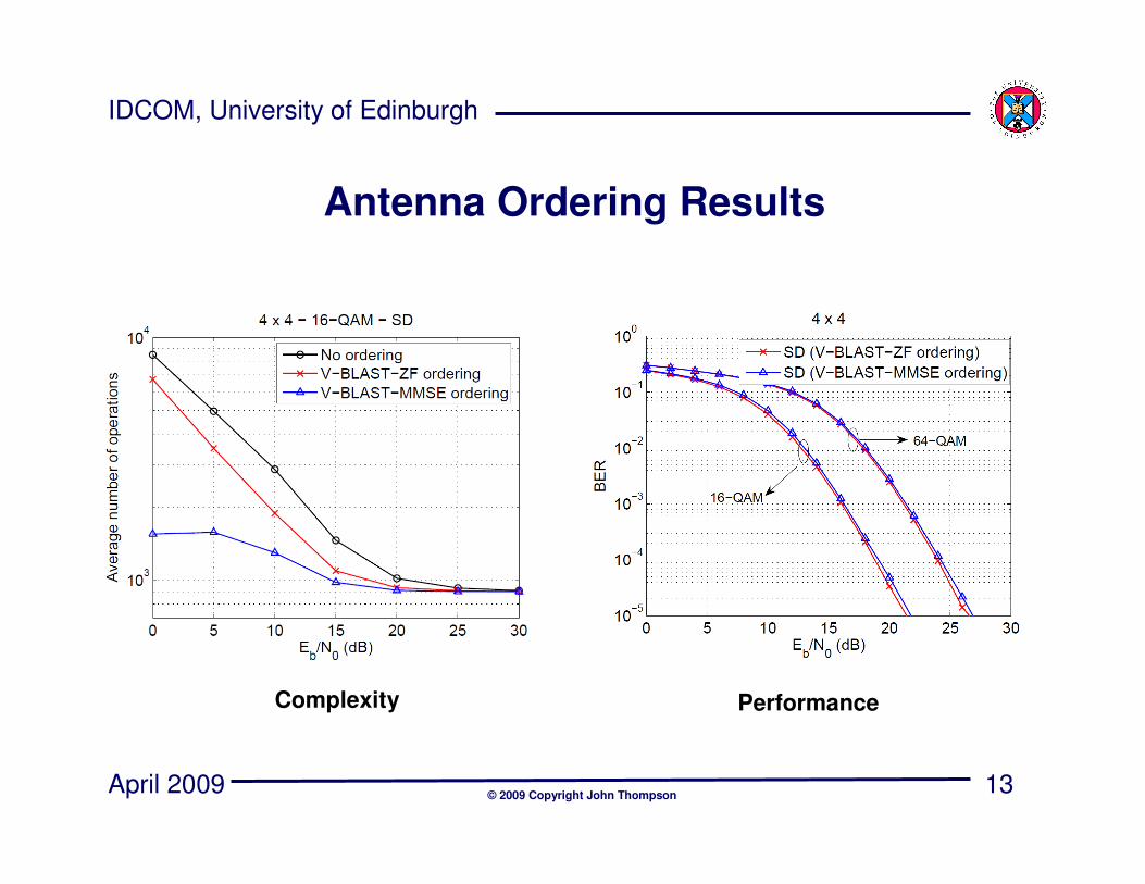
Antenna Ordering
Antennas can also be ordered before sphere
decoding:
– VBLAST-ZF ordering: order antennas by increasing
noise amplification (reducing SNR)
– VBLAST-MMSE ordering: order antennas by
decreasing signal-to-interference & noise ratio
• MMSE reduces complexity compared to ZF but
suffers slight performance degradation
13
IDCOM, University of Edinburgh
April 2009© 2009 Copyright John Thompson
Antenna Ordering Results
Complexity Performance
14
IDCOM, University of Edinburgh
April 2009© 2009 Copyright John Thompson
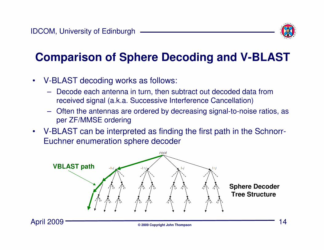
VBLAST path
Sphere Decoder
Tree Structure
Comparison of Sphere Decoding and V-BLAST
• V-BLAST decoding works as follows:
– Decode each antenna in turn, then subtract out decoded data from
received signal (a.k.a. Successive Interference Cancellation)
– Often the antennas are ordered by decreasing signal-to-noise ratios, as
per ZF/MMSE ordering
• V-BLAST can be interpreted as finding the first path in the Schnorr-Euchner enumeration sphere decoder
15
IDCOM, University of Edinburgh
April 2009© 2009 Copyright John Thompson
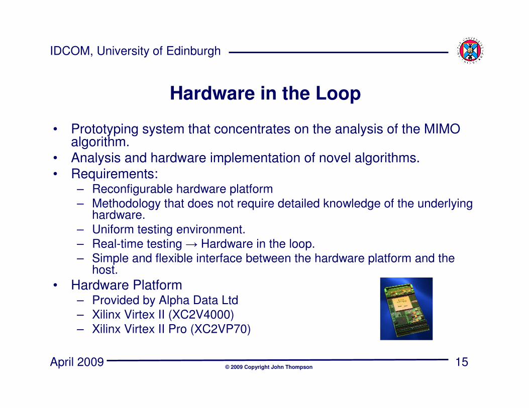
Hardware in the Loop
• Prototyping system that concentrates on the analysis of the MIMOalgorithm.
• Analysis and hardware implementation of novel algorithms.• Requirements:
– Reconfigurable hardware platform
– Methodology that does not require detailed knowledge of the underlying hardware.
– Uniform testing environment.
– Real-time testing → Hardware in the loop.
– Simple and flexible interface between the hardware platform and the host.
• Hardware Platform– Provided by Alpha Data Ltd
– Xilinx Virtex II (XC2V4000)
– Xilinx Virtex II Pro (XC2VP70)
16
IDCOM, University of Edinburgh
April 2009© 2009 Copyright John Thompson
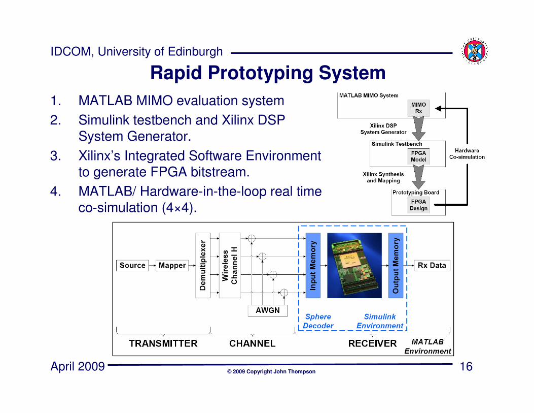
Rapid Prototyping System
1. MATLAB MIMO evaluation system
2. Simulink testbench and Xilinx DSP System Generator.
3. Xilinx’s Integrated Software Environment to generate FPGA bitstream.
4. MATLAB/ Hardware-in-the-loop real time co-simulation (4×4).
17
IDCOM, University of Edinburgh
April 2009© 2009 Copyright John Thompson
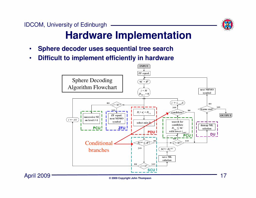
• Sphere decoder uses sequential tree search
• Difficult to implement efficiently in hardware
Hardware Implementation
Sphere Decoding
Algorithm Flowchart
Conditional
branches
18
IDCOM, University of Edinburgh
April 2009© 2009 Copyright John Thompson
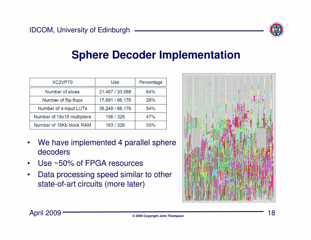
Sphere Decoder Implementation
• We have implemented 4 parallel sphere decoders
• Use ~50% of FPGA resources
• Data processing speed similar to other state-of-art circuits (more later)
19
IDCOM, University of Edinburgh
April 2009© 2009 Copyright John Thompson
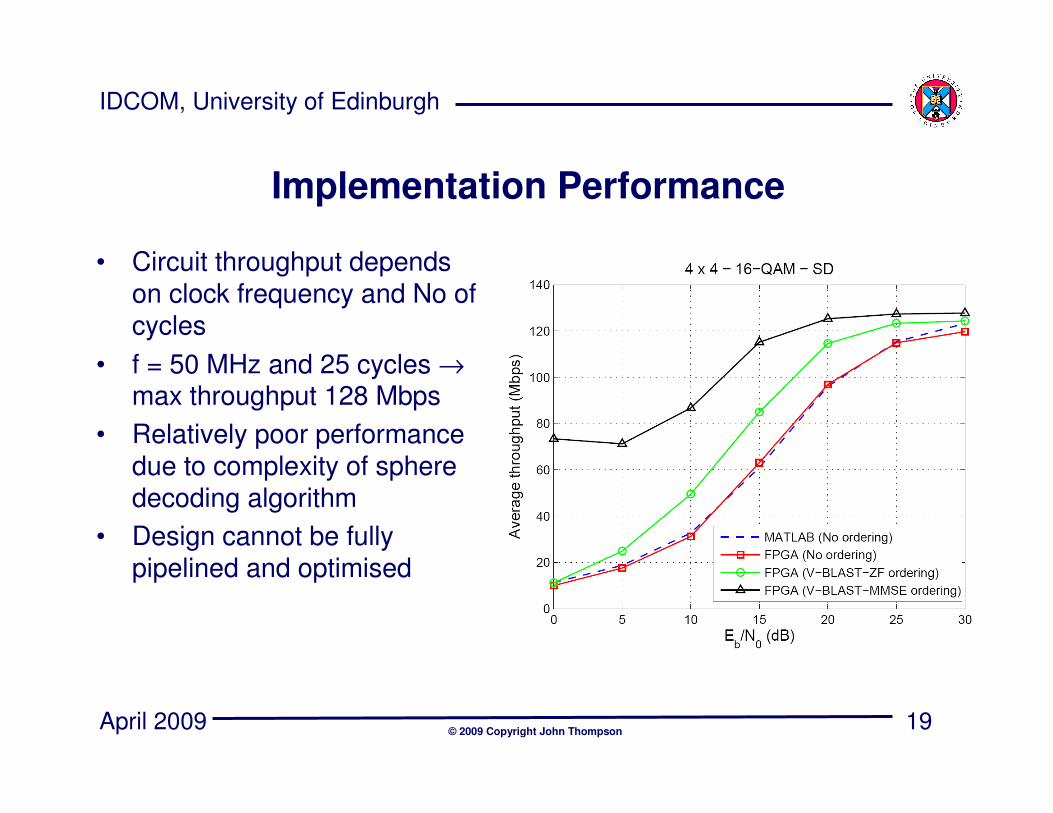
Implementation Performance
• Circuit throughput depends on clock frequency and No of cycles
• f = 50 MHz and 25 cycles →max throughput 128 Mbps
• Relatively poor performance due to complexity of sphere decoding algorithm
• Design cannot be fully pipelined and optimised
20
IDCOM, University of Edinburgh
April 2009© 2009 Copyright John Thompson
Motivation for Fixed Sphere Decoder
• Disadvantages of the sphere decoder:– Variable complexity poses problem in actual communication
systems where data needs to be processed in a fixed number of operations.
– Its sequential search results in a hardware implementation that is not fully pipelined, affecting the achievable throughput.
• Modifications of the sphere decoder to marginally reduce the average complexity require additional operations or calculation of limiting thresholds.– It results in a more complex hardware implementation without
achieving a fixed complexity.
• The K-best lattice decoder (based on the sequential M-algorithm) provides a fixed complexity.– It does not take into consideration the MIMO system model
resulting in high complexity.
21
IDCOM, University of Edinburgh
April 2009© 2009 Copyright John Thompson
Fixed Sphere Decoder Algorithm
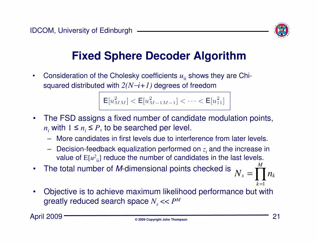
• Consideration of the Cholesky coefficients uii shows they are Chi-
squared distributed with 2(N−i+1) degrees of freedom
• The FSD assigns a fixed number of candidate modulation points, ni with 1 ≤ ni ≤ P, to be searched per level.
– More candidates in first levels due to interference from later levels.
– Decision-feedback equalization performed on zi and the increase in
value of E[u2ii] reduce the number of candidates in the last levels.
• The total number of M-dimensional points checked is
• Objective is to achieve maximum likelihood performance but with greatly reduced search space Ns << PM
∏=
=M
k
ks nN1
22
IDCOM, University of Edinburgh
April 2009© 2009 Copyright John Thompson
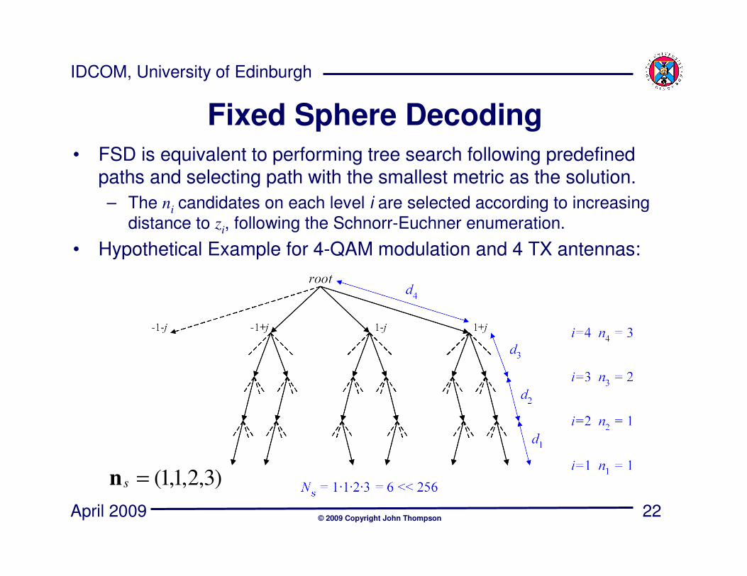
Fixed Sphere Decoding• FSD is equivalent to performing tree search following predefined
paths and selecting path with the smallest metric as the solution.
– The ni candidates on each level i are selected according to increasing
distance to zi, following the Schnorr-Euchner enumeration.
• Hypothetical Example for 4-QAM modulation and 4 TX antennas:
)3,2,1,1(=sn
23
IDCOM, University of Edinburgh
April 2009© 2009 Copyright John Thompson
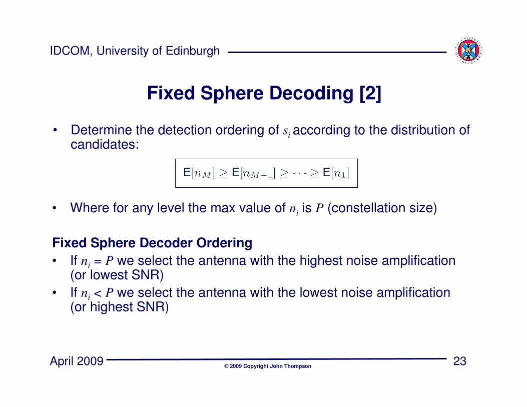
Fixed Sphere Decoding [2]
• Determine the detection ordering of si according to the distribution of candidates:
• Where for any level the max value of ni is P (constellation size)
Fixed Sphere Decoder Ordering
• If ni = P we select the antenna with the highest noise amplification (or lowest SNR)
• If ni < P we select the antenna with the lowest noise amplification (or highest SNR)
24
IDCOM, University of Edinburgh
April 2009© 2009 Copyright John Thompson
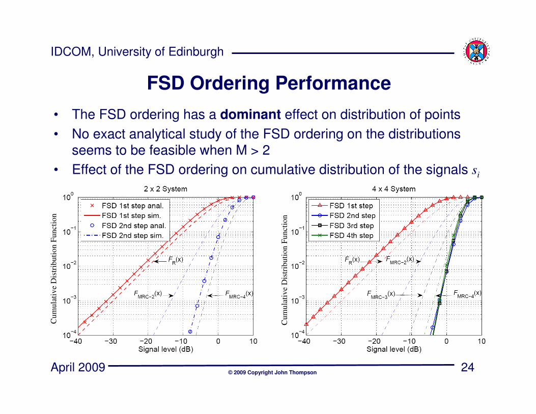
FSD Ordering Performance
• The FSD ordering has a dominant effect on distribution of points
• No exact analytical study of the FSD ordering on the distributions seems to be feasible when M > 2
• Effect of the FSD ordering on cumulative distribution of the signals si
Cum
ula
tiv
e D
istr
ibuti
on F
unct
ion
Cum
ula
tiv
e D
istr
ibuti
on F
unct
ion
25
IDCOM, University of Edinburgh
April 2009© 2009 Copyright John Thompson
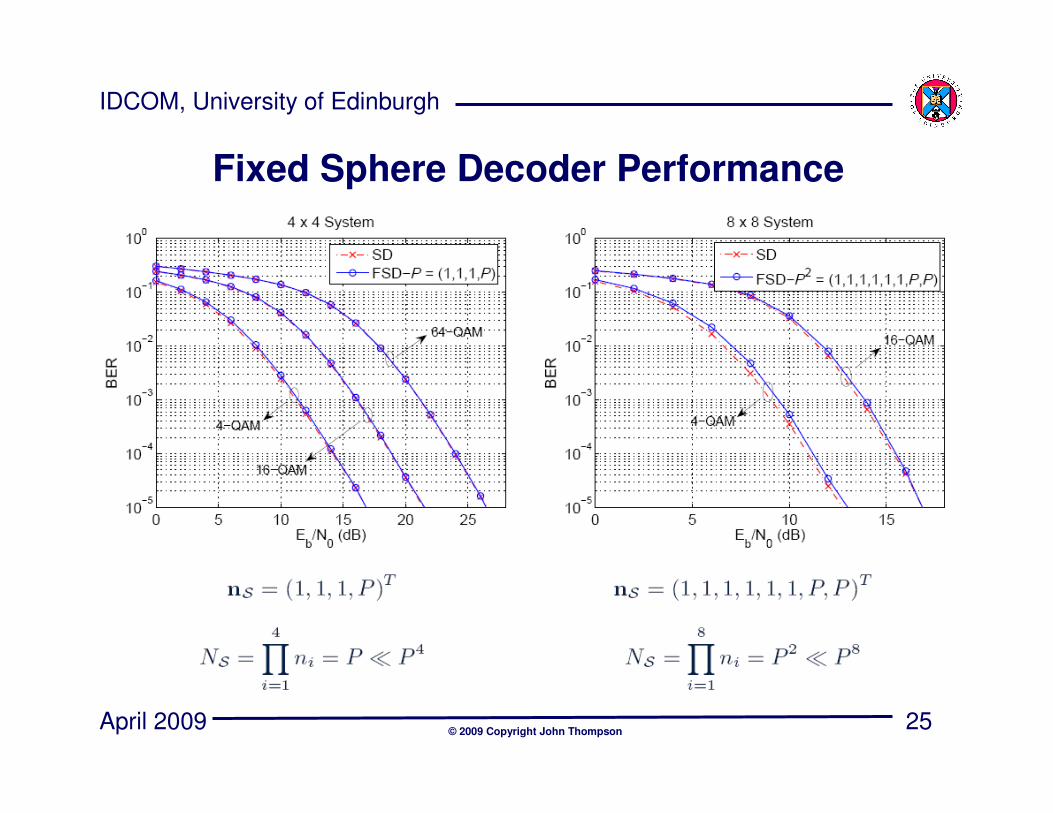
Fixed Sphere Decoder Performance
26
IDCOM, University of Edinburgh
April 2009© 2009 Copyright John Thompson
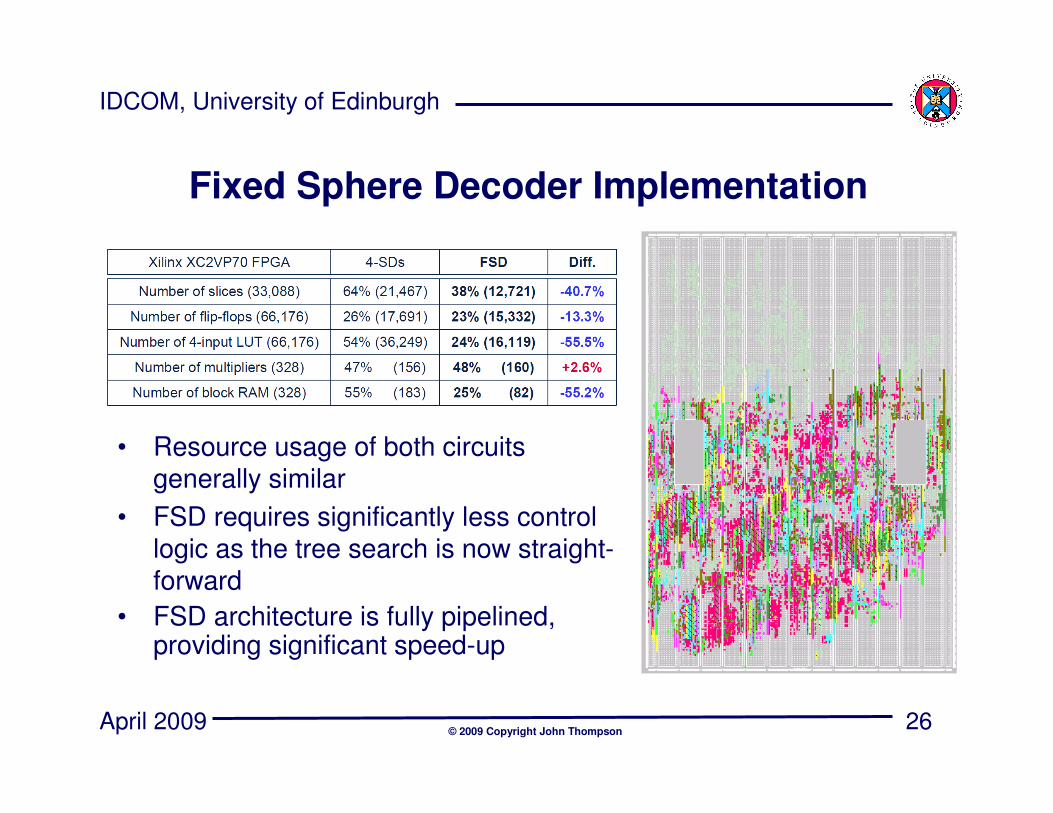
Fixed Sphere Decoder Implementation
• Resource usage of both circuits generally similar
• FSD requires significantly less control logic as the tree search is now straight-forward
• FSD architecture is fully pipelined, providing significant speed-up

27
IDCOM, University of Edinburgh
April 2009© 2009 Copyright John Thompson
FSD Hardware Implementation
• FSD algorithm can be fully pipelined unlike sphere decoder case
• f = 100 MHz and 4 cycles →max throughput 400 Mbps
• Throughput is fixed and is independent of Eb/No
• FSD algorithm provides much better hardware performance than sphere decoder
28
IDCOM, University of Edinburgh
April 2009© 2009 Copyright John Thompson
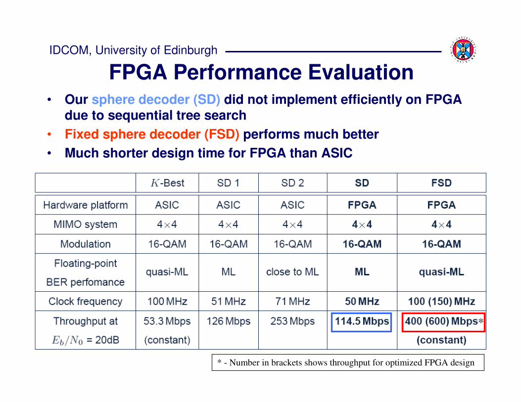
FPGA Performance Evaluation• Our sphere decoder (SD) did not implement efficiently on FPGA
due to sequential tree search
• Fixed sphere decoder (FSD) performs much better
• Much shorter design time for FPGA than ASIC
* - Number in brackets shows throughput for optimized FPGA design
*
29
IDCOM, University of Edinburgh
April 2009© 2009 Copyright John Thompson
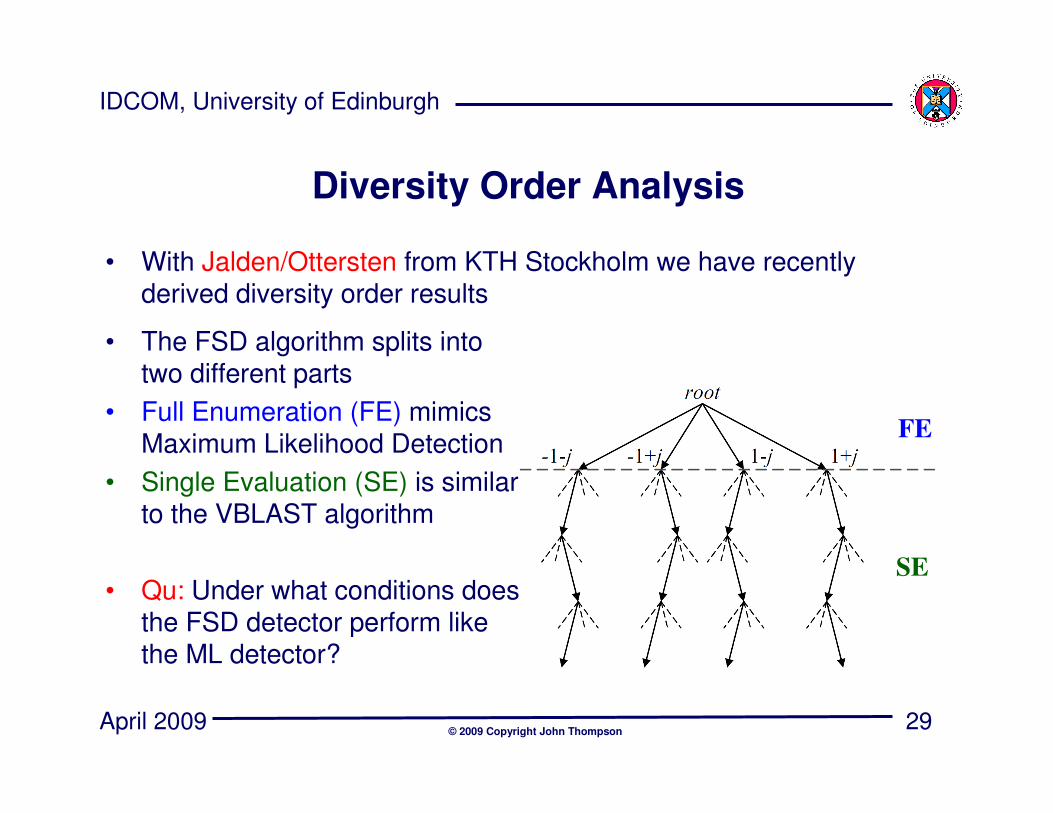
Diversity Order Analysis
• With Jalden/Ottersten from KTH Stockholm we have recently derived diversity order results
• The FSD algorithm splits into two different parts
• Full Enumeration (FE) mimics Maximum Likelihood Detection
• Single Evaluation (SE) is similar to the VBLAST algorithm
• Qu: Under what conditions does the FSD detector perform like the ML detector?
FE
SE
30
IDCOM, University of Edinburgh
April 2009© 2009 Copyright John Thompson
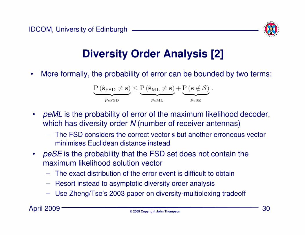
Diversity Order Analysis [2]
• More formally, the probability of error can be bounded by two terms:
• peML is the probability of error of the maximum likelihood decoder, which has diversity order N (number of receiver antennas)
– The FSD considers the correct vector s but another erroneous vector
minimises Euclidean distance instead
• peSE is the probability that the FSD set does not contain the maximum likelihood solution vector
– The exact distribution of the error event is difficult to obtain
– Resort instead to asymptotic diversity order analysis
– Use Zheng/Tse’s 2003 paper on diversity-multiplexing tradeoff
31
IDCOM, University of Edinburgh
April 2009© 2009 Copyright John Thompson
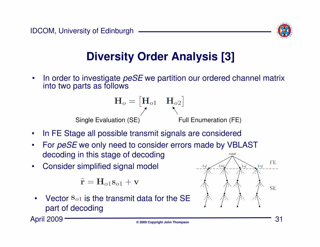
Diversity Order Analysis [3]
• In order to investigate peSE we partition our ordered channel matrix into two parts as follows
Single Evaluation (SE) Full Enumeration (FE)
• In FE Stage all possible transmit signals are considered
• For peSE we only need to consider errors made by VBLAST decoding in this stage of decoding
• Consider simplified signal model
• Vector is the transmit data for the SE part of decoding

32
IDCOM, University of Edinburgh
April 2009© 2009 Copyright John Thompson
Error Analysis of SE Stage
• Diversity order of detection of SE stage depends on distribution of smallest eigenvalue of SE Gram matrix
• This problem may look extremely hard to solve!
• However, it turns out that we can make a link to the complete channel matrix H and its ordered (permuted) version Ho
• The main result of the analysis is a relation between the eigenvalues of H and Ho as follows:
• Here we assume p FE levels and (M-p) SE levels in FSD detector
• Interpretation: smallest eigenvalue of has the same diversity order as that of the (p+1)th sorted eigenvalue of
33
IDCOM, University of Edinburgh
April 2009© 2009 Copyright John Thompson
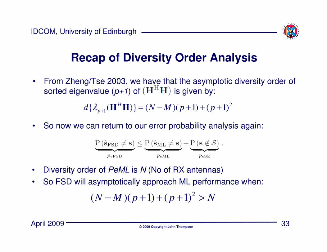
Recap of Diversity Order Analysis
• From Zheng/Tse 2003, we have that the asymptotic diversity order of sorted eigenvalue (p+1) of is given by:
2
1 )1()1)(()}({ +++−=+ ppMNdH
p HHλ
• So now we can return to our error probability analysis again:
• Diversity order of PeML is N (No of RX antennas)
• So FSD will asymptotically approach ML performance when:
NppMN >+++−2)1()1)((
34
IDCOM, University of Edinburgh
April 2009© 2009 Copyright John Thompson
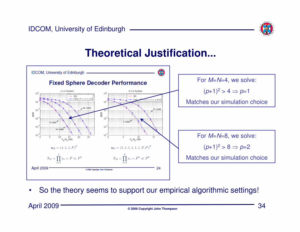
Theoretical Justification...
For M=N=4, we solve:
(p+1)2 > 4 ⇒ p=1
Matches our simulation choice
For M=N=8, we solve:
(p+1)2 > 8 ⇒ p=2
Matches our simulation choice
• So the theory seems to support our empirical algorithmic settings!
35
IDCOM, University of Edinburgh
April 2009© 2009 Copyright John Thompson
The Islay Project
• In Summer 2008, we started a £1.2M EPSRC multi-disciplinary project in the area of efficient algorithm design and prototyping
– Algorithm Design: John Thompson (UoE) and Andrew Wallace (HWU)
– Hume Language Development: Greg Michelson (HWU) and Kevin
Hammond (StA)
– FPGA Tool Development: John McAllister and Roger Woods (QUB)
• Seek closer links between algorithm development & implementation
• Two representative algorithms for demonstration
– Sphere Decoding for MIMO Systems
– Monte Carlo Markov Chain Detection Algorithms for LIDAR
36
IDCOM, University of Edinburgh
April 2009© 2009 Copyright John Thompson
Current Research
• Improved K-Best Algorithm– Combining K-Best approach with an MMSE metric
appears to reduce complexity a lot– Hardware implementation runs at same speed as
FSD (less multipliers, more logic operations)
• Thresholding FSD Tree Search– Basic FSD computes tree in parallel fashion– Instead check quality of first few tree branches
– If we have found a likely solution, do not need to computer remaining tree branch metrics
– Can reduce power consumption/improve data throughput
37
IDCOM, University of Edinburgh
April 2009© 2009 Copyright John Thompson
Conclusions
• We have seen that the sphere decoder does not give an efficient hardware implementation due to tree search
• Fixed sphere decoder algorithm overcomes this problem by fixing the number of points searched per antenna– Allows for an efficient, pipelined hardware implementation
– Achieves close to maximum likelihood performance
• Implemented a list fixed sphere decoder to compute soft metrics for decoding of convolutional/turbo codes– Need to modify number of points per level for good soft metrics
– Optimised iterative decoding with list decoder
• Hard/soft decoding work will be further developed in the Islay project
38
IDCOM, University of Edinburgh
April 2009© 2009 Copyright John Thompson
Web Sites
• Fixed Sphere Decoder Homepage:
http://www.eng.ed.ac.uk/~jst/sphere/
• The Islay Project Homepage:
http://www.eng.ed.ac.uk/~idcomislay/