Embed Size (px)
Citation preview
Copyright © 2011 Raritan, Inc.
PXE-0A-v2.2.10-E
September 2011
255-80-0008-00
Raritan PXE
User Guide Release 2.2.10

WARNING! Read and understand all sections in this guide before installing or operating this product.
WARNING! Connect this product to an AC power source whose voltage is within the range specified on the product’s nameplate. Operating this product outside the nameplate voltage range may result in electric shock, fire, personal injury and death.
WARNING! Connect this product to an AC power source that is current limited by a suitably rated fuse or circuit breaker in accordance with national and local electrical codes. Operating this product without proper current limiting may result in electric shock, fire, personal injury and death.
WARNING! Connect this product to a protective earth ground. Never use a “ground lift adaptor” between the product’s plug and the wall receptacle. Failure to connect to a protective earth ground may result in electric shock, fire, personal injury and death.
WARNING! This product contains no user serviceable parts. Do not open, alter or disassemble this product. All servicing must be performed by qualified personnel. Disconnect power before servicing this product. Failure to comply with this warning may result in electric shock, personal injury and death.
WARNING! Use this product in a dry location. Failure to use this product in a dry location may result in electric shock, personal injury and death.
WARNING! Do not rely on this product’s receptacle lamps, receptacle relay switches or any other receptacle power on/off indicator to determine whether power is being supplied to a receptacle. Unplug a device connected to this product before performing repair, maintenance or service on the device. Failure to unplug a device before servicing it may result in electric shock, fire, personal injury and death.
WARNING! Only use this product to power information technology equipment that has a UL/IEC 60950-1 or equivalent rating. Attempting to power non-rated devices may result in electric shock, fire, personal injury and death.
WARNING! Do not use this product to power inductive loads such as motors or compressors. Attempting to power inductive loads may result in damage to the product.
WARNING! Do not use this product to power critical patient care equipment, fire or smoke alarm systems. Use of this product to power such equipment may result in personal injury and death.
WARNING! If this product is a model that requires assembly of its line cord or plug, all such assembly must be performed by a licensed electrician and the line cord or plugs used must be suitably rated based on the product’s nameplate ratings and national and local electrical codes. Assembly by unlicensed electricians or failure to use suitably rated line cords or plugs may result in electric shock, fire, personal injury or death.
WARNING! This product contains a chemical known to the State of California to cause cancer, birth defects, or other reproductive harm.
Safety Guidelines
1. Installation of this product should only be performed by a person who has knowledge and experience with electric power.
2. Make sure the line cord is disconnected from power before physically mounting or moving the location of this product.
3. This product is designed to be used within an electronic equipment rack. The metal case of this product is electrically bonded to the line cord ground wire. A threaded grounding point on the case may be used as an additional means of protectively grounding this product and the rack.
4. Examine the branch circuit receptacle that will supply electric power to this product. Make sure the receptacle’s power lines, neutral and protective earth ground pins are wired correctly and are the correct voltage and phase. Make sure the branch circuit receptacle is protected by a suitably rated fuse or circuit breaker.
5. If the product is a model that contains receptacles that can be switched on/off, electric power may still be present at a receptacle even when it is switched off.
Safety Instructions

This document contains proprietary information that is protected by copyright. All rights reserved. No part of this document may be photocopied, reproduced, or translated into another language without express prior written consent of Raritan, Inc.
© Copyright 2011 Raritan, Inc. All third-party software and hardware mentioned in this document are registered trademarks or trademarks of and are the property of their respective holders.
FCC Information
This equipment has been tested and found to comply with the limits for a Class A digital device, pursuant to Part 15 of the FCC Rules. These limits are designed to provide reasonable protection against harmful interference in a commercial installation. This equipment generates, uses, and can radiate radio frequency energy and if not installed and used in accordance with the instructions, may cause harmful interference to radio communications. Operation of this equipment in a residential environment may cause harmful interference.
VCCI Information (Japan)
Raritan is not responsible for damage to this product resulting from accident, disaster, misuse, abuse, non-Raritan modification of the product, or other events outside of Raritan's reasonable control or not arising under normal operating conditions.

v
Contents
Safety Guidelines ii
Safety Instructions iii
Chapter 1 Introduction 1
Product Models ..............................................................................................................................1 Product Features ...........................................................................................................................1 Package Contents..........................................................................................................................2
Zero U Products...................................................................................................................3 1U Products .........................................................................................................................3
Chapter 2 Rack-Mounting the PDU 4
Rackmount Safety Guidelines .......................................................................................................4 Circuit Breaker Orientation Limitation............................................................................................4 Mounting 1U Models Using L-Brackets and Buttons .....................................................................5 Mounting Zero U Models Using Two Rear Buttons .......................................................................6 Mounting Zero U Models Using L-Brackets and Buttons...............................................................8
Chapter 3 Installation and Configuration 10
Before You Begin.........................................................................................................................10 Unpacking the Product and Components..........................................................................10 Preparing the Installation Site............................................................................................10 Filling Out the Equipment Setup Worksheet .....................................................................11 Checking the Branch Circuit Rating...................................................................................11
Connecting the PDU to a Power Source .....................................................................................11 Configuring the Raritan PXE........................................................................................................12
Connecting the Raritan PXE to a Computer......................................................................13 Installing the USB-to-Serial Driver.....................................................................................13 Connecting the Raritan PXE to Your Network...................................................................15 Initial Network Configuration..............................................................................................15
Installing Cable Retention Clips on Outlets (Optional) ................................................................20 Connecting Environmental Sensors (Optional) ...........................................................................22
About Contact Closure Sensors ........................................................................................24
Contents
vi
How to Connect Differential Air Pressure Sensors............................................................27
Chapter 4 Using the PDU 28
Panel Components ......................................................................................................................28 Power Cord........................................................................................................................28 Outlets ...............................................................................................................................28 Connection Ports ...............................................................................................................29 LED Display .......................................................................................................................30 Reset Button......................................................................................................................33
Circuit Breakers ...........................................................................................................................33 Resetting the Button-Type Circuit Breaker........................................................................33 Resetting the Handle-Type Circuit Breaker.......................................................................34
Beeper .........................................................................................................................................35
Chapter 5 Using the Web Interface 36
Supported Web Browsers............................................................................................................36 Logging in to the Web Interface...................................................................................................37
Login ..................................................................................................................................37 Changing Your Password..................................................................................................38
Logout ..........................................................................................................................................39 Introduction to the Web Interface.................................................................................................40
Menus ................................................................................................................................41 Dominion PX Explorer Pane..............................................................................................41 Setup Button......................................................................................................................44 Status Bar ..........................................................................................................................44 Add Page Icon ...................................................................................................................45 Logout Button ....................................................................................................................46 Data Pane..........................................................................................................................46 More Information ...............................................................................................................46
Viewing the Dashboard................................................................................................................51 Device Management ....................................................................................................................51
Displaying the PDU Information ........................................................................................52 Naming the PDU................................................................................................................53 Modifying the Network Configuration.................................................................................53 Modifying the Network Service Settings............................................................................58 Setting the Date and Time.................................................................................................61 Specifying the Device Altitude ...........................................................................................64 Setting Data Logging .........................................................................................................65 Configuring the SMTP Settings .........................................................................................66 Setting the EnergyWise Configuration ..............................................................................67 Rebooting the Raritan PXE Device ...................................................................................67
User Management .......................................................................................................................68 Creating a User Profile ......................................................................................................68 Modifying a User Profile ....................................................................................................71 Deleting a User Profile.......................................................................................................72 Changing the User List View .............................................................................................72
Contents
vii
Setting Up Roles ..........................................................................................................................73 Creating a Role..................................................................................................................73 Modifying a Role................................................................................................................74 Deleting a Role ..................................................................................................................75 Changing the Role List View .............................................................................................75
Access Security Control...............................................................................................................75 Forcing HTTPS Encryption................................................................................................76 Configuring the Firewall.....................................................................................................76 Setting Up User Login Controls .........................................................................................81 Setting Up Role-Based Access Control Rules ..................................................................84
Setting Up an SSL Certificate ......................................................................................................87 Certificate Signing Request ...............................................................................................88 Creating a Self-Signed Certificate .....................................................................................90 Installing Existing Key and Certificate Files.......................................................................91 Downloading Key and Certificate Files..............................................................................92
Setting Up LDAP Authentication..................................................................................................92 Gathering the LDAP Information .......................................................................................93 Adding the LDAP Server Settings .....................................................................................93 Sorting the LDAP Access Order ........................................................................................96 Testing the LDAP Server Connection ...............................................................................96 Editing the LDAP Server Settings......................................................................................97 Deleting the LDAP Server Settings ...................................................................................97 Disabling the LDAP Authentication ...................................................................................97 Enabling LDAP and Local Authentication Services...........................................................98
Outlet Management .....................................................................................................................98 Naming Outlets ..................................................................................................................98 Checking Associated Circuit Breakers ..............................................................................99
Inlet and Circuit Breaker Management ........................................................................................99 Naming the Inlet ..............................................................................................................100 Monitoring the Inlet ..........................................................................................................100 Naming Circuit Breakers..................................................................................................101
Setting Power Thresholds..........................................................................................................102 Setting Inlet Thresholds...................................................................................................102 What is Deassertion Hysteresis?.....................................................................................103 What is Assertion Timeout?.............................................................................................104
Configuring Event Rules ............................................................................................................105 Components of an Event Rule.........................................................................................105 Creating an Event Rule ...................................................................................................105 Sample Event Rules ........................................................................................................112 Modifying an Event Rule..................................................................................................113 Modifying an Action .........................................................................................................114 Deleting an Event Rule or Action.....................................................................................114 A Note about Untriggered Rules......................................................................................115
Managing Event Logging ...........................................................................................................115 Viewing the Local Event Log ...........................................................................................115 Clearing Event Entries.....................................................................................................116
Viewing Connected Users .........................................................................................................116 Monitoring Server Accessibility..................................................................................................117
Adding IT Devices for Ping Monitoring ............................................................................117 Editing Ping Monitoring Settings......................................................................................118 Deleting Ping Monitoring Settings ...................................................................................119 Checking Server Monitoring States.................................................................................119
Contents
viii
Environmental Sensors..............................................................................................................120 Identifying Environmental Sensors..................................................................................121 Managing Environmental Sensors...................................................................................122 Configuring Environmental Sensors................................................................................123 Viewing Sensor Data .......................................................................................................126 Unmanaging Environmental Sensors..............................................................................129
Copying Configurations with Bulk Configuration .......................................................................130 Saving a Raritan PXE Configuration ...............................................................................131 Copying a Raritan PXE Configuration .............................................................................132
Changing the Measurement Units .............................................................................................132 Network Diagnostics ..................................................................................................................134
Pinging a Host .................................................................................................................134 Tracing the Network Route..............................................................................................134 Listing TCP Connections .................................................................................................135
Viewing the Communication Log ...............................................................................................135 Downloading Diagnostic Information .........................................................................................136 Firmware Upgrade .....................................................................................................................136
Updating the Raritan PXE Firmware ...............................................................................137 Viewing Firmware Update History ...................................................................................138 Full Disaster Recovery ....................................................................................................139
Accessing the Help ....................................................................................................................139 Retrieving Software Packages Information .....................................................................139 Browsing through the Online Help...................................................................................140
Chapter 6 Using SNMP 142
Enabling SNMP..........................................................................................................................142 Configuring Users for Encrypted SNMP v3 ...............................................................................143 Configuring SNMP Traps...........................................................................................................144 SNMP Gets and Sets.................................................................................................................145
The Raritan PXE MIB ......................................................................................................145 A Note about Enabling Thresholds..................................................................................147
Chapter 7 Using the Command Line Interface 148
About the Interface.....................................................................................................................148 Logging in to CLI........................................................................................................................148
With HyperTerminal.........................................................................................................149 With SSH or Telnet..........................................................................................................150 Different CLI Modes and Prompts ...................................................................................151 Closing a Serial Connection ............................................................................................151
Help Command..........................................................................................................................151 Showing Information ..................................................................................................................152
Network Configuration .....................................................................................................152 IP Configuration...............................................................................................................152 LAN Interface Settings.....................................................................................................153 Networking Mode.............................................................................................................153 Network Service Settings ................................................................................................153 PDU Configuration...........................................................................................................154
Contents
ix
Outlet Information ............................................................................................................154 Inlet Information...............................................................................................................155 Circuit Breaker Information..............................................................................................156 Environmental Sensor Information ..................................................................................157 Inlet Sensor Threshold Information .................................................................................158 Inlet Pole Sensor Threshold Information .........................................................................159 Environmental Sensor Threshold Information .................................................................160 Security Settings..............................................................................................................161 Existing User Profiles ......................................................................................................161 Existing Roles ..................................................................................................................162 EnergyWise Settings .......................................................................................................162 Reliability Data.................................................................................................................162 Reliability Error Log .........................................................................................................163 Command History............................................................................................................163 History Buffer Length.......................................................................................................163 Examples .........................................................................................................................163
Configuring the Raritan PXE Device and Network ....................................................................165 Entering the Configuration Mode.....................................................................................165 PDU Configuration Commands .......................................................................................166 Networking Configuration Commands.............................................................................168 Security Configuration Commands..................................................................................185 Outlet Configuration Commands .....................................................................................205 Inlet Configuration Commands........................................................................................205 Circuit Breaker Configuration Commands.......................................................................206 Environmental Sensor Configuration Commands ...........................................................207 Sensor Threshold Configuration Commands ..................................................................211 User Configuration Commands .......................................................................................230 Role Configuration Commands .......................................................................................241 EnergyWise Configuration Commands ...........................................................................246 Setting the History Buffer Length.....................................................................................249 Multi-Command Syntax ...................................................................................................249 Quitting the Configuration Mode......................................................................................250
Unblocking a User......................................................................................................................250 Resetting the Raritan PXE.........................................................................................................251
Restarting the PDU..........................................................................................................251 Resetting to Factory Defaults ..........................................................................................251
Network Troubleshooting...........................................................................................................251 Entering the Diagnostic Mode .........................................................................................252 Diagnostic Commands ....................................................................................................252 Quitting the Diagnostic Mode ..........................................................................................255
Contents
x
Querying Available Parameters for a Command .......................................................................255 Retrieving Previous Commands ................................................................................................255 Automatically Completing a Command......................................................................................256 Logging out of CLI......................................................................................................................256
Appendix A Specifications 257
Power Measurement Accuracy..................................................................................................257 Maximum Ambient Operating Temperature ..............................................................................257 Raritan PXE Feature RJ-12 Port Pinouts ..................................................................................257 RS-485 Port Pinouts ..................................................................................................................258
Appendix B Equipment Setup Worksheet 259
Appendix C Resetting to Factory Defaults 263
Using the CLI Command ...........................................................................................................263
Appendix D LDAP Configuration Illustration 264
Step A. Determine User Accounts and Groups .........................................................................264 Step B. Configure User Groups on the AD Server ....................................................................265 Step C. Configure LDAP Authentication on the Raritan PXE Device........................................266 Step D. Configure User Groups on the Raritan PXE Device.....................................................268
Appendix E Integration 272
Power IQ Configuration .............................................................................................................272 Adding PDUs to Power IQ Management.........................................................................272
RF Code Energy Monitoring Solution ........................................................................................274
Appendix F Additional Raritan PXE Information 275
MAC Address.............................................................................................................................275 Altitude Correction Factors ........................................................................................................275
Index 277
1
The Raritan PXE is an intelligent power distribution unit (PDU) that allows you to remotely monitor power in the server room or data center.
The intended use of the Raritan PXE is distribution of power to information technology equipment such as computers and communication equipment where such equipment is typically mounted in an equipment rack located in an information technology equipment room.
In This Chapter
Product Models..........................................................................................1 Product Features .......................................................................................1 Package Contents .....................................................................................2
Product Models
The Raritan PXE comes in several models that are built to stock and can be obtained almost immediately. Raritan also offers custom models that are built to order and can only be obtained on request.
Visit the Product Selector page (http://www.raritan.com/resources/px-product-selector/) on the Raritan website or contact your local reseller for a list of available models.
Product Features
The Raritan PXE models vary in sizes. In general, the Raritan PXE features include:
The ability to monitor the following at the inlet level:
- Active energy (Wh)
- Active power (W)
- Apparent power (VA)
- Power factor
- RMS current per line (A)
- RMS voltage per line pair (V)
Chapter 1 Introduction
Chapter 1: Introduction
2
The ability to monitor environmental factors such as external temperature and humidity
User-specified location attributes for environmental sensors
An audible alarm (beeper) to indicate current overload
Configurable alarm thresholds and hysteresis
Configurable assertion timeout for thresholds
Support for SNMP v1, v2, and v3
The ability to send traps using the SNMP protocol
The ability to store a data log of all sensor measurements and retrieve it via SNMP
Note: Raritan's Power IQ or other external systems can retrieve the stored data (samples) from the Raritan PXE.
The ability to configure and set values through SNMP, including power threshold levels
The ability to save one Raritan PXE device's configuration settings and then deploy those settings to other Raritan PXE devices
Support for both of IPv4 and IPv6 networking
Support for Baytech BSNMP
Support for Cisco EnergyWise
Support for RF Code energy monitoring system
Local overcurrent protection (OCP) via branch circuit breakers or fuses on products rated over 20A to protect connected equipment against overload and short circuits
A combination of outlet types (for example, C13 and C19 outlets) in select models
A combination of outlet voltages (120 and 208 volts) in select models
Support for high current devices (such as Blade Servers) in select models
The ability to diagnose the network, such as pinging a host or listing TCP connections
Full disaster recovery option in case of a catastrophic failure during a firmware upgrade
The ability to display temperatures in Celsius or Fahrenheit, height in meters or feet, and pressure in Pascal or psi according to user credentials
Package Contents
The following sub-topics describe the equipment and other material included in the product package.
Chapter 1: Introduction
3
Zero U Products
The Raritan PXE device
Mounting screws, brackets and/or buttons
Cable retention clips for outlets (optional)
1U Products
The Raritan PXE device
Mounting screws, brackets and/or buttons
4
This chapter describes how to rackmount a Raritan PXE device.
In This Chapter
Rackmount Safety Guidelines ...................................................................4 Circuit Breaker Orientation Limitation........................................................4 Mounting 1U Models Using L-Brackets and Buttons.................................5 Mounting Zero U Models Using Two Rear Buttons...................................6 Mounting Zero U Models Using L-Brackets and Buttons ..........................8
Rackmount Safety Guidelines
In Raritan products which require rack mounting, follow these precautions:
Operation temperature in a closed rack environment may be greater than room temperature. Do not exceed the rated maximum ambient temperature of the Power Distribution Units. See Specifications (on page 257) in the User Guide.
Ensure sufficient airflow through the rack environment.
Mount equipment in the rack carefully to avoid uneven mechanical loading.
Connect equipment to the supply circuit carefully to avoid overloading circuits.
Ground all equipment properly, especially supply connections, to the branch circuit.
Circuit Breaker Orientation Limitation
Usually a PDU can be mounted in any orientation. However, when mounting a PDU with circuit breakers, you must obey these rules:
Circuit breakers CANNOT face down. For example, do not horizontally mount a Zero U PDU with circuit breakers on ceiling.
If a rack is subject to shock in environments such as boats or airplanes, the PDU CANNOT be mounted upside down. If installed upside down, shock stress reduces the trip point by 10%.
Note: If normally the line cord is down, upside down means the line cord is up.
Chapter 2 Rack-Mounting the PDU
Chapter 2: Rack-Mounting the PDU
5
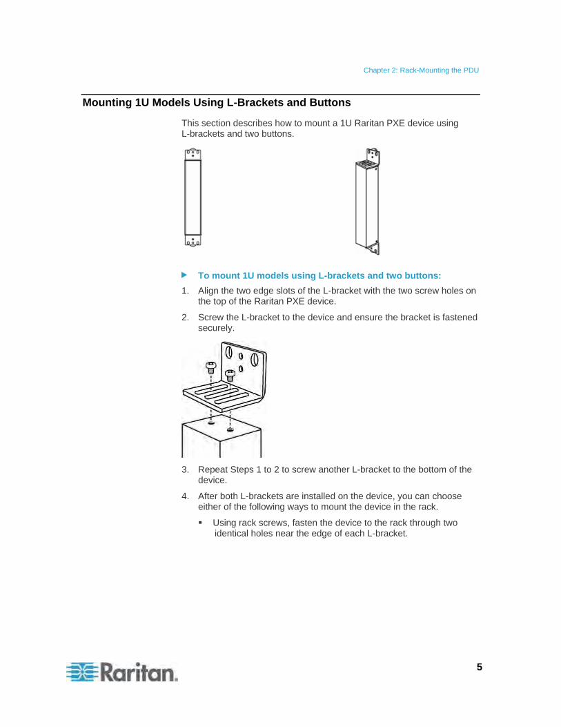
Mounting 1U Models Using L-Brackets and Buttons
This section describes how to mount a 1U Raritan PXE device using L-brackets and two buttons.
To mount 1U models using L-brackets and two buttons:
1. Align the two edge slots of the L-bracket with the two screw holes on the top of the Raritan PXE device.
2. Screw the L-bracket to the device and ensure the bracket is fastened securely.
3. Repeat Steps 1 to 2 to screw another L-bracket to the bottom of the device.
4. After both L-brackets are installed on the device, you can choose either of the following ways to mount the device in the rack.
Using rack screws, fasten the device to the rack through two identical holes near the edge of each L-bracket.

Chapter 2: Rack-Mounting the PDU
6
Mount the device by screwing a mounting button in the back center of each L-bracket and then having both buttons engage the mounting holes in the rack. The recommended torque for the button is 1.96 N·m (20 kgf·cm).
Mounting Zero U Models Using Two Rear Buttons
The following describes how to mount a PDU using two buttons only. If your PDU has circuit breakers implemented, read Circuit Breaker Orientation Limitation (on page 4) before mounting it.
To mount Zero U models using two buttons:
1. Turn to the rear of the PDU.
Chapter 2: Rack-Mounting the PDU
7
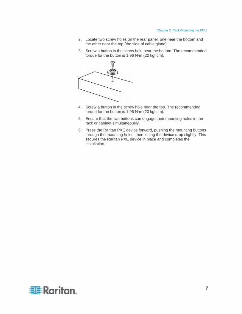
2. Locate two screw holes on the rear panel: one near the bottom and the other near the top (the side of cable gland).
3. Screw a button in the screw hole near the bottom. The recommended torque for the button is 1.96 N·m (20 kgf·cm).
4. Screw a button in the screw hole near the top. The recommended torque for the button is 1.96 N·m (20 kgf·cm).
5. Ensure that the two buttons can engage their mounting holes in the rack or cabinet simultaneously.
6. Press the Raritan PXE device forward, pushing the mounting buttons through the mounting holes, then letting the device drop slightly. This secures the Raritan PXE device in place and completes the installation.
Chapter 2: Rack-Mounting the PDU
8
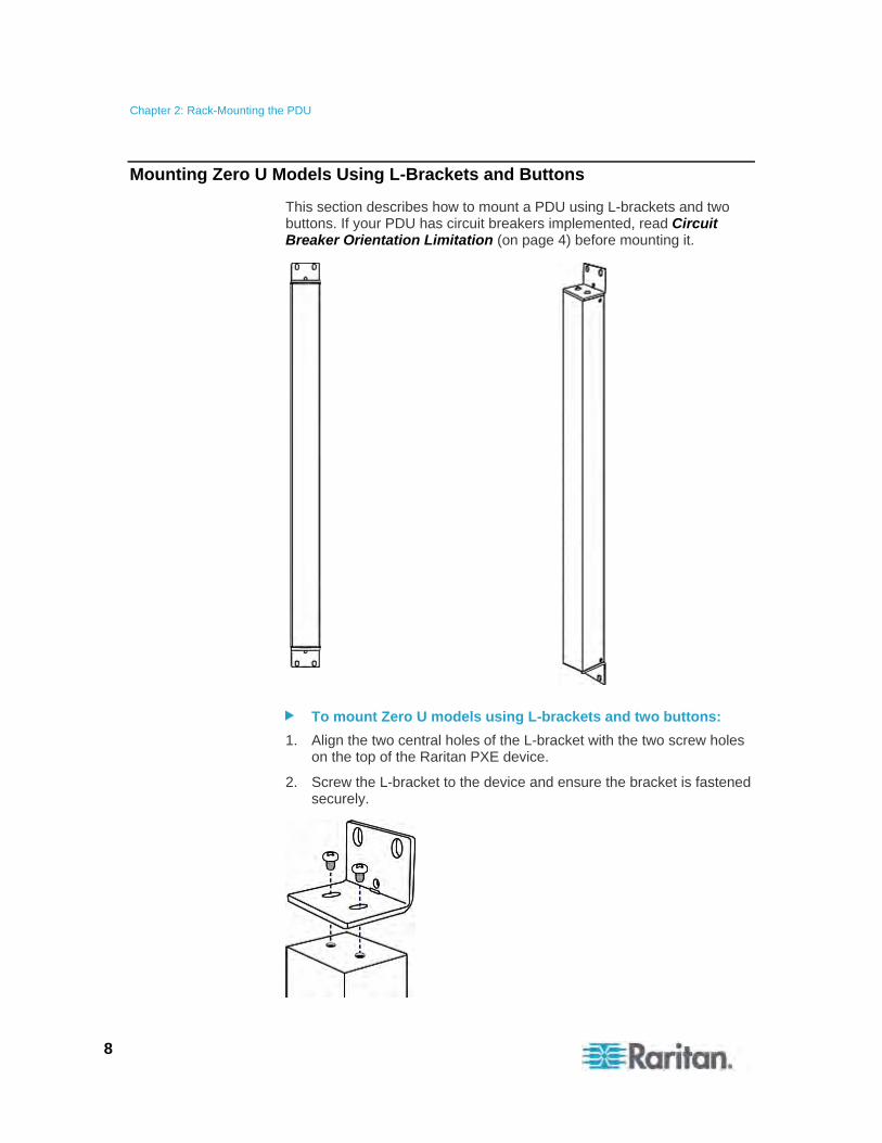
Mounting Zero U Models Using L-Brackets and Buttons
This section describes how to mount a PDU using L-brackets and two buttons. If your PDU has circuit breakers implemented, read Circuit Breaker Orientation Limitation (on page 4) before mounting it.
To mount Zero U models using L-brackets and two buttons:
1. Align the two central holes of the L-bracket with the two screw holes on the top of the Raritan PXE device.
2. Screw the L-bracket to the device and ensure the bracket is fastened securely.
Chapter 2: Rack-Mounting the PDU
9
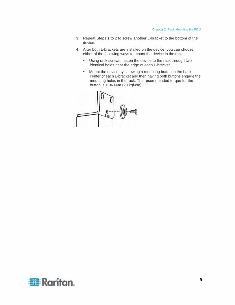
3. Repeat Steps 1 to 2 to screw another L-bracket to the bottom of the device.
4. After both L-brackets are installed on the device, you can choose either of the following ways to mount the device in the rack.
Using rack screws, fasten the device to the rack through two identical holes near the edge of each L-bracket.
Mount the device by screwing a mounting button in the back center of each L-bracket and then having both buttons engage the mounting holes in the rack. The recommended torque for the button is 1.96 N·m (20 kgf·cm).

10
This chapter explains how to install a Raritan PXE device and configure it for network connectivity.
In This Chapter
Before You Begin ....................................................................................10 Connecting the PDU to a Power Source .................................................11 Configuring the Raritan PXE ...................................................................12 Installing Cable Retention Clips on Outlets (Optional) ............................20 Connecting Environmental Sensors (Optional) .......................................22
Before You Begin
Before beginning the installation, perform the following activities:
Unpack the product and components
Prepare the installation site
Fill out the equipment setup worksheet
Check the branch circuit rating
Unpacking the Product and Components
1. Remove the Raritan PXE device and other equipment from the box in which they were shipped. See Package Contents (on page 2) for a complete list of the contents of the box.
2. Compare the serial number of the equipment with the number on the packing slip located on the outside of the box and make sure they match.
3. Inspect the equipment carefully. If any of the equipment is damaged or missing, contact Raritan's Technical Support Department for assistance.
4. Verify that all circuit breakers on the Raritan PXE device are set to ON. If not, turn them ON.
For a PDU with fuses, ensure that all fuses are inserted and seated properly. If there are any fuse covers, ensure that they are closed.
Note: Not all Raritan PXE devices have overcurrent protection mechanisms.
Preparing the Installation Site
1. Make sure the installation area is clean and free of extreme temperatures and humidity.
Chapter 3 Installation and Configuration
Chapter 3: Installation and Configuration
11
Note: If necessary, contact Raritan Technical Support for the maximum operating temperature for your model. See Maximum Ambient Operating Temperature (on page 257).
2. Allow sufficient space around the Raritan PXE device for cabling and outlet connections.
3. Review the Safety Instructions (on page iii) listed in the beginning of this user guide.
Filling Out the Equipment Setup Worksheet
An Equipment Setup Worksheet is provided in this guide. See Equipment Setup Worksheet (on page 259). Use this worksheet to record the model, serial number, and use of each IT device connected to the PDU.
As you add and remove devices, keep the worksheet up-to-date.
Checking the Branch Circuit Rating
This section describes the rating of the branch circuit supplying power to the PDU:
The rating of the branch circuit shall be in accordance with national and local electrical codes.
For North American, the rating of the branch circuit may be up to 125% greater than the rating of the PDU, unless prohibited by national or local electrical codes.
20A for PDUs rated at 16A input current
30A for PDUs rated at 24A input current
40A for PDUs rated at 32A input current
50A for PDUs rated at 35A input current
50A for PDUs rated at 40A input current
60A for PDUs rated at 45A input current
In North America, external overcurrent protectors shall be certified by UL/CSA (or equivalent certification). In other regions or countries, make sure they comply with national and local electrical codes.
Connecting the PDU to a Power Source
1. Verify that all circuit breakers on the Raritan PXE device are set to ON. If not, turn them ON.
For a PDU with fuses, ensure that all fuses are inserted and seated properly. If there are any fuse covers, ensure that they are closed.
Chapter 3: Installation and Configuration
12
Note: Not all Raritan PXE devices have overcurrent protection mechanisms.
2. Connect each Raritan PXE device to an appropriately rated branch circuit. See the label or nameplate affixed to your Raritan PXE device for appropriate input ratings or range of ratings.
3. When a Raritan PXE device powers up, it proceeds with the power-on self test and software loading for a few moments.
4. When the software has completed loading, the LED display illuminates and shows numeric digits.
Configuring the Raritan PXE
There are two alternatives to initially configure a Raritan PXE device:
Connect the Raritan PXE device to a computer to configure it, using a serial or USB connection between Raritan PXE and the computer.
The computer must have a communications program such as HyperTerminal or PuTTY.
For a serial connection, you need a null-modem cable with DB9 connectors on both ends (Raritan part number: 254-01-0006-00).
Connect the Raritan PXE device to a TCP/IP network that supports DHCP.
The DHCP-assigned IP address of the PDU can be retrieved through the PDU's MAC address. You can contact your LAN administrator for assistance. See MAC Address (on page 275).
A Category 5e/6 UTP cable is required for a wired connection.
Chapter 3: Installation and Configuration
13
Connecting the Raritan PXE to a Computer
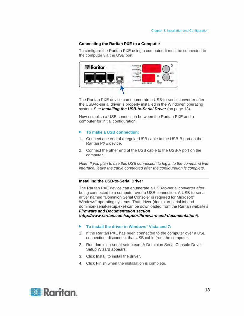
To configure the Raritan PXE using a computer, it must be connected to the computer via the USB port.
The Raritan PXE device can enumerate a USB-to-serial converter after the USB-to-serial driver is properly installed in the Windows® operating system. See Installing the USB-to-Serial Driver (on page 13).
Now establish a USB connection between the Raritan PXE and a computer for initial configuration.
To make a USB connection:
1. Connect one end of a regular USB cable to the USB-B port on the Raritan PXE device.
2. Connect the other end of the USB cable to the USB-A port on the computer.
Note: If you plan to use this USB connection to log in to the command line interface, leave the cable connected after the configuration is complete.
Installing the USB-to-Serial Driver
The Raritan PXE device can enumerate a USB-to-serial converter after being connected to a computer over a USB connection. A USB-to-serial driver named "Dominion Serial Console" is required for Microsoft® Windows® operating systems. That driver (dominion-serial.inf and dominion-serial-setup.exe) can be downloaded from the Raritan website's Firmware and Documentation section (http://www.raritan.com/support/firmware-and-documentation/).
To install the driver in Windows® Vista and 7:
1. If the Raritan PXE has been connected to the computer over a USB connection, disconnect that USB cable from the computer.
2. Run dominion-serial-setup.exe. A Dominion Serial Console Driver Setup Wizard appears.
3. Click Install to install the driver.
4. Click Finish when the installation is complete.
Chapter 3: Installation and Configuration
14
5. Re-connect the Raritan PXE to the computer via a USB cable. The driver is automatically installed.
To install the driver in Windows® XP:
1. If the Raritan PXE has been connected to the computer over a USB connection, disconnect that USB cable from the computer.
2. Check if the file "usbser.sys" is available in C:\Windows\ServicePackFiles\i386. If not, extract it from the Windows installation CD disc, and copy it to the same directory where the USB-to-serial driver is stored.
On a CD disc with SP3 included, it is extracted from I386\SP3.CAB.
On a CD disc with SP2 included, it is extracted from I386\SP2.CAB.
On a CD without any SP, it is extracted from I386\DRIVER.CAB.
3. Re-connect the Raritan PXE to the computer via a USB cable.
4. The computer detects the new device and the "Found New Hardware Wizard" dialog appears. If this dialog does not appear, choose Control Panel > System > Hardware > Device Manager, right-click the Dominion Serial Console, and choose Update Driver.
5. Select "Install from a list or specific location," and manually specify the location where the driver is stored.
6. If it asks for the file "usbser.sys," specify the location where that file exists.
7. The installation is now complete.
In Linux:
No additional drivers are required, but you must provide the name of the tty device, which can be found in the output of the "dmesg" after connecting the Raritan PXE device to the computer. Usually the tty device is "/dev/ttyACM#" or "/dev/ttyUSB#," where # is an integer number.
For example, if you are using the kermit terminal program, and the tty device is "/dev/ttyACM0," perform the following commands:
> set line /dev/ttyACM0
> connect
Chapter 3: Installation and Configuration
15
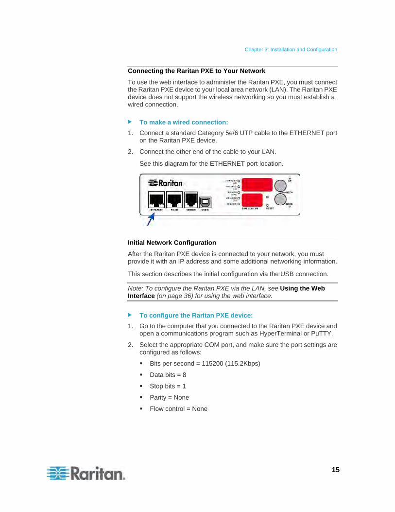
Connecting the Raritan PXE to Your Network
To use the web interface to administer the Raritan PXE, you must connect the Raritan PXE device to your local area network (LAN). The Raritan PXE device does not support the wireless networking so you must establish a wired connection.
To make a wired connection:
1. Connect a standard Category 5e/6 UTP cable to the ETHERNET port on the Raritan PXE device.
2. Connect the other end of the cable to your LAN.
See this diagram for the ETHERNET port location.
Initial Network Configuration
After the Raritan PXE device is connected to your network, you must provide it with an IP address and some additional networking information.
This section describes the initial configuration via the USB connection.
Note: To configure the Raritan PXE via the LAN, see Using the Web Interface (on page 36) for using the web interface.
To configure the Raritan PXE device:
1. Go to the computer that you connected to the Raritan PXE device and open a communications program such as HyperTerminal or PuTTY.
2. Select the appropriate COM port, and make sure the port settings are configured as follows:
Bits per second = 115200 (115.2Kbps)
Data bits = 8
Stop bits = 1
Parity = None
Flow control = None
Chapter 3: Installation and Configuration
16
Tip: For a USB connection, you can find out which COM port is assigned to the Raritan PXE by choosing Control Panel > System > Hardware > Device Manager, and locating the "Dominion Serial Console" under the Ports group.
3. Press Enter.
4. The Raritan PXE prompts you to log in. Note that both of user name and password are case sensitive.
a. At the Username prompt, type admin and press Enter.
b. At the Password prompt, type raritan and press Enter.
5. You are prompted to change the password if this is the first time you log in to the Raritan PXE device. Follow the onscreen instructions to type your new password.
6. The # prompt appears when you log in successfully.
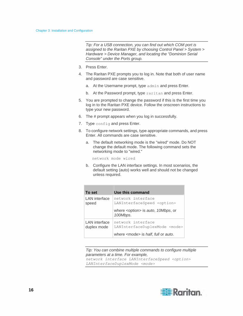
7. Type config and press Enter.
8. To configure network settings, type appropriate commands, and press Enter. All commands are case sensitive.
a. The default networking mode is the "wired" mode. Do NOT change the default mode. The following command sets the networking mode to "wired."
network mode wired
b. Configure the LAN interface settings. In most scenarios, the default setting (auto) works well and should not be changed unless required.
To set Use this command
LAN interface speed
network interface LANInterfaceSpeed <option>
where <option> is auto, 10Mbps, or 100Mbps.
LAN interface duplex mode
network interface LANInterfaceDuplexMode <mode>
where <mode> is half, full or auto.
Tip: You can combine multiple commands to configure multiple parameters at a time. For example, network interface LANInterfaceSpeed <option> LANInterfaceDuplexMode <mode>
Chapter 3: Installation and Configuration
17
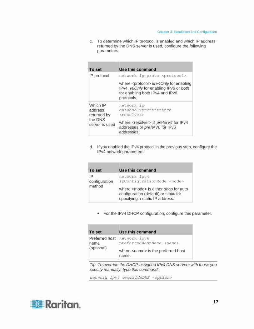
c. To determine which IP protocol is enabled and which IP address returned by the DNS server is used, configure the following parameters.
To set Use this command
IP protocol network ip proto <protocol>
where <protocol> is v4Only for enabling IPv4, v6Only for enabling IPv6 or both for enabling both IPv4 and IPv6 protocols.
Which IP address returned by the DNS server is used
network ip dnsResolverPreference <resolver>
where <resolver> is preferV4 for IPv4 addresses or preferV6 for IPv6 addresses.
d. If you enabled the IPv4 protocol in the previous step, configure the IPv4 network parameters.
To set Use this command
IP configuration method
network ipv4 ipConfigurationMode <mode>
where <mode> is either dhcp for auto configuration (default) or static for specifying a static IP address.
For the IPv4 DHCP configuration, configure this parameter.
To set Use this command
Preferred host name (optional)
network ipv4 preferredHostName <name>
where <name> is the preferred host name.
Tip: To override the DHCP-assigned IPv4 DNS servers with those you specify manually, type this command:
network ipv4 overrideDNS <option>
Chapter 3: Installation and Configuration
18
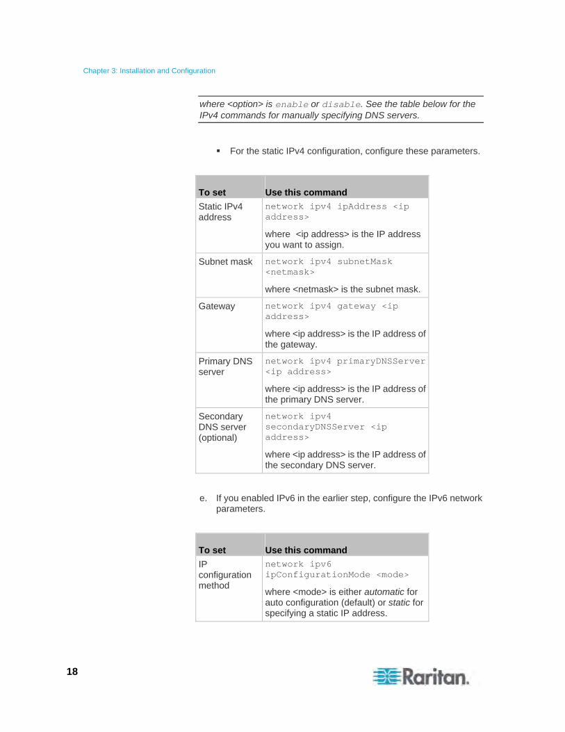
where <option> is enable or disable. See the table below for the IPv4 commands for manually specifying DNS servers.
For the static IPv4 configuration, configure these parameters.
To set Use this command
Static IPv4 address
network ipv4 ipAddress <ip address>
where <ip address> is the IP address you want to assign.
Subnet mask network ipv4 subnetMask <netmask>
where <netmask> is the subnet mask.
Gateway network ipv4 gateway <ip address>
where <ip address> is the IP address of the gateway.
Primary DNS server
network ipv4 primaryDNSServer <ip address>
where <ip address> is the IP address of the primary DNS server.
Secondary DNS server (optional)
network ipv4 secondaryDNSServer <ip address>
where <ip address> is the IP address of the secondary DNS server.
e. If you enabled IPv6 in the earlier step, configure the IPv6 network parameters.
To set Use this command
IP configuration method
network ipv6 ipConfigurationMode <mode>
where <mode> is either automatic for auto configuration (default) or static for specifying a static IP address.
Chapter 3: Installation and Configuration
19
Tip: To override the DHCP-assigned IPv6 DNS servers with those you specify manually, type this command:
network ipv6 overrideDNS <option>
where <option> is enable or disable. See the table below for the IPv6 commands for manually specifying DNS servers.
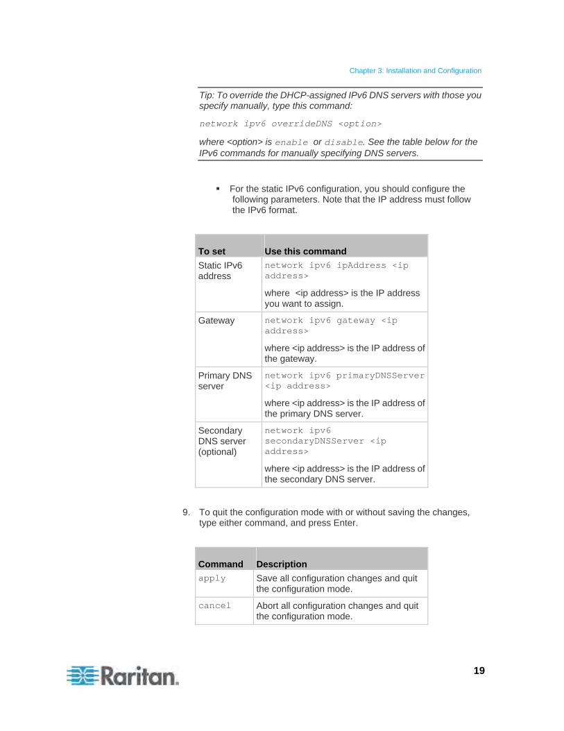
For the static IPv6 configuration, you should configure the following parameters. Note that the IP address must follow the IPv6 format.
To set Use this command
Static IPv6 address
network ipv6 ipAddress <ip address>
where <ip address> is the IP address you want to assign.
Gateway network ipv6 gateway <ip address>
where <ip address> is the IP address of the gateway.
Primary DNS server
network ipv6 primaryDNSServer <ip address>
where <ip address> is the IP address of the primary DNS server.
Secondary DNS server (optional)
network ipv6 secondaryDNSServer <ip address>
where <ip address> is the IP address of the secondary DNS server.
9. To quit the configuration mode with or without saving the changes, type either command, and press Enter.
Command Description
apply Save all configuration changes and quit the configuration mode.
cancel Abort all configuration changes and quit the configuration mode.
Chapter 3: Installation and Configuration
20
The # prompt appears, indicating that you have quit the configuration mode.
10. To verify whether all settings are correct, type the following commands one by one. Current network settings are displayed.
Command Description
show network Show network parameters.
show network ip all Show all IP configuration parameters.
11. If all are correct, type exit to log out of the Raritan PXE. If any are incorrect, repeat Steps 7 to 10 to change any network settings.
The IP address configured may take seconds to take effect.
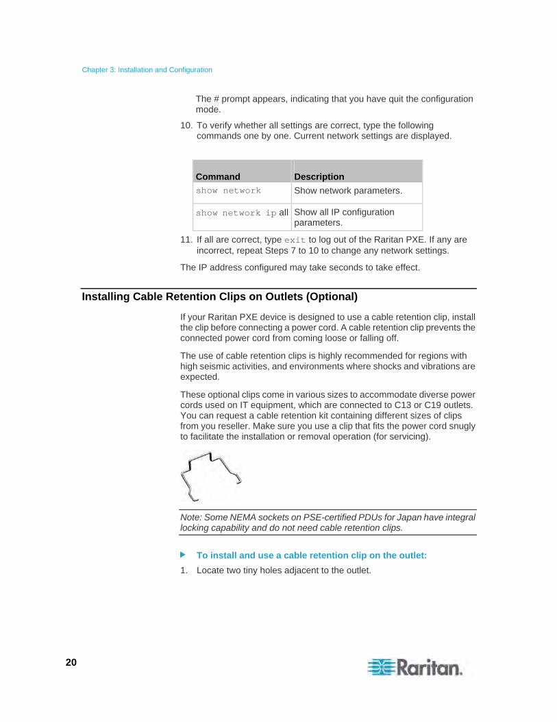
Installing Cable Retention Clips on Outlets (Optional)
If your Raritan PXE device is designed to use a cable retention clip, install the clip before connecting a power cord. A cable retention clip prevents the connected power cord from coming loose or falling off.
The use of cable retention clips is highly recommended for regions with high seismic activities, and environments where shocks and vibrations are expected.
These optional clips come in various sizes to accommodate diverse power cords used on IT equipment, which are connected to C13 or C19 outlets. You can request a cable retention kit containing different sizes of clips from you reseller. Make sure you use a clip that fits the power cord snugly to facilitate the installation or removal operation (for servicing).
Note: Some NEMA sockets on PSE-certified PDUs for Japan have integral locking capability and do not need cable retention clips.
To install and use a cable retention clip on the outlet:
1. Locate two tiny holes adjacent to the outlet.
Chapter 3: Installation and Configuration
21
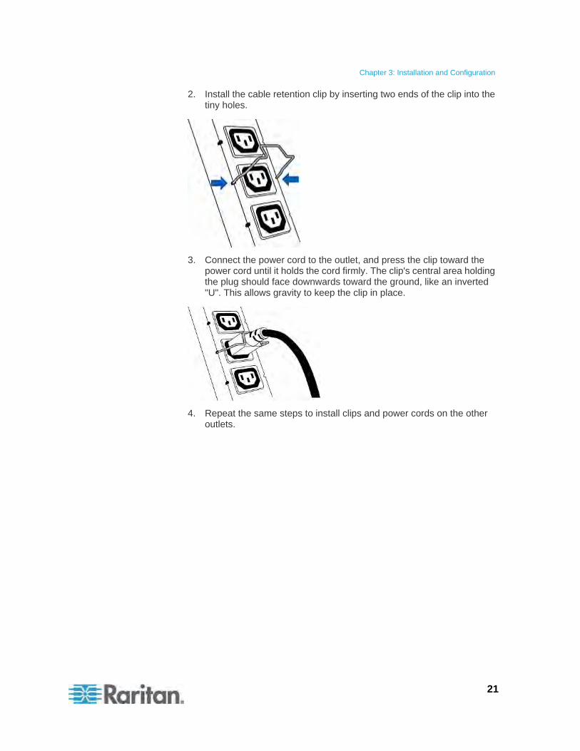
2. Install the cable retention clip by inserting two ends of the clip into the tiny holes.
3. Connect the power cord to the outlet, and press the clip toward the power cord until it holds the cord firmly. The clip's central area holding the plug should face downwards toward the ground, like an inverted "U". This allows gravity to keep the clip in place.
4. Repeat the same steps to install clips and power cords on the other outlets.
Chapter 3: Installation and Configuration
22
Connecting Environmental Sensors (Optional)
To enable the detection of environmental factors around the rack, connect one or more Raritan environmental sensors to the Raritan PXE device.
The maximum distance for all sensor cabling plugged into the product's sensor port should not exceed 30 meters/100 feet. Contact Raritan Technical Support if you have questions.
You can connect up to 16 environmental sensors to a Raritan PXE device by using a Raritan sensor hub.
Note that a Raritan environmental sensor usually contains more than one sensor. For example, a DPX-T2H2 counts as 4 sensors, and a DPX-T3H1 counts as 4 sensors.
Warning: For proper operation, wait for 15~30 seconds between each connection operation or each disconnection operation of environmental sensors.
To directly connect one or multiple environmental sensors:
Plug the connector of the environmental sensor into the SENSOR port on your Raritan PXE device.
Note: Depending on the model you purchased, the total number of SENSOR ports varies.
To connect environmental sensors via an optional PX sensor hub:
1. Connect a Raritan sensor hub to the Raritan PXE device.
a. Plug one end of the Raritan-provided phone cable (4-wire, 6-pin, RJ-12) into the IN port (Port 1) of the hub.
b. Plug the other end into the SENSOR port on the Raritan PXE device.
2. Connect Raritan environmental sensors to any of the four OUT ports on the hub.
Chapter 3: Installation and Configuration
23
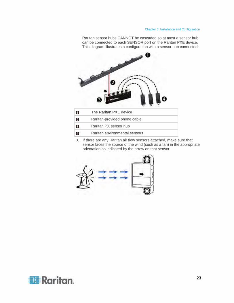
Raritan sensor hubs CANNOT be cascaded so at most a sensor hub can be connected to each SENSOR port on the Raritan PXE device. This diagram illustrates a configuration with a sensor hub connected.
The Raritan PXE device
Raritan-provided phone cable
Raritan PX sensor hub
Raritan environmental sensors
3. If there are any Raritan air flow sensors attached, make sure that sensor faces the source of the wind (such as a fan) in the appropriate orientation as indicated by the arrow on that sensor.
Chapter 3: Installation and Configuration
24
About Contact Closure Sensors
Raritan's contact closure sensor (DPX-CC2-TR) can detect the open-and-closed status of the connected detectors/switches. It requires the integration of at least a discrete (on/off) detector/switch to work properly. The types of discrete detectors/switches that can be plugged into DPX-CC2-TR include those for:
Door open/closed detection
Door lock detection
Floor water detection
Smoke detection
Vibration detection
Raritan does NOT provide these discrete detectors/switches. They are third-party probes so you must test them with Raritan's DPX-CC2-TR to ensure they work properly.
Integration and testing for third-party detectors/switches is the sole responsibility of the customer. Raritan cannot assume any liability as a result of improper termination or failure (incidental or consequential) of third-party detectors/switches that customers provide and install. Failure to follow installation and configuration instructions can result in false alarms or no alarms. Raritan makes no statement or claim that all third-party detectors/switches will work with DPX-CC2-TR.
Connecting Third-Party Detectors/Switches to DPX-CC2-TR
A DPX-CC2-TR unit provides two channels for connecting two third-party detectors/switches. There are four spring-loaded termination points on the body of DPX-CC2-TR: the two to the right are associated with one channel (as indicated by the LED number), and the two to the left are associated with another channel. You must plug the third-party detectors/switches into these termination points.
To connect third-party detectors/switches:
1. Strip the insulation around 12mm from the end of each wire of two third-party detectors/switches.
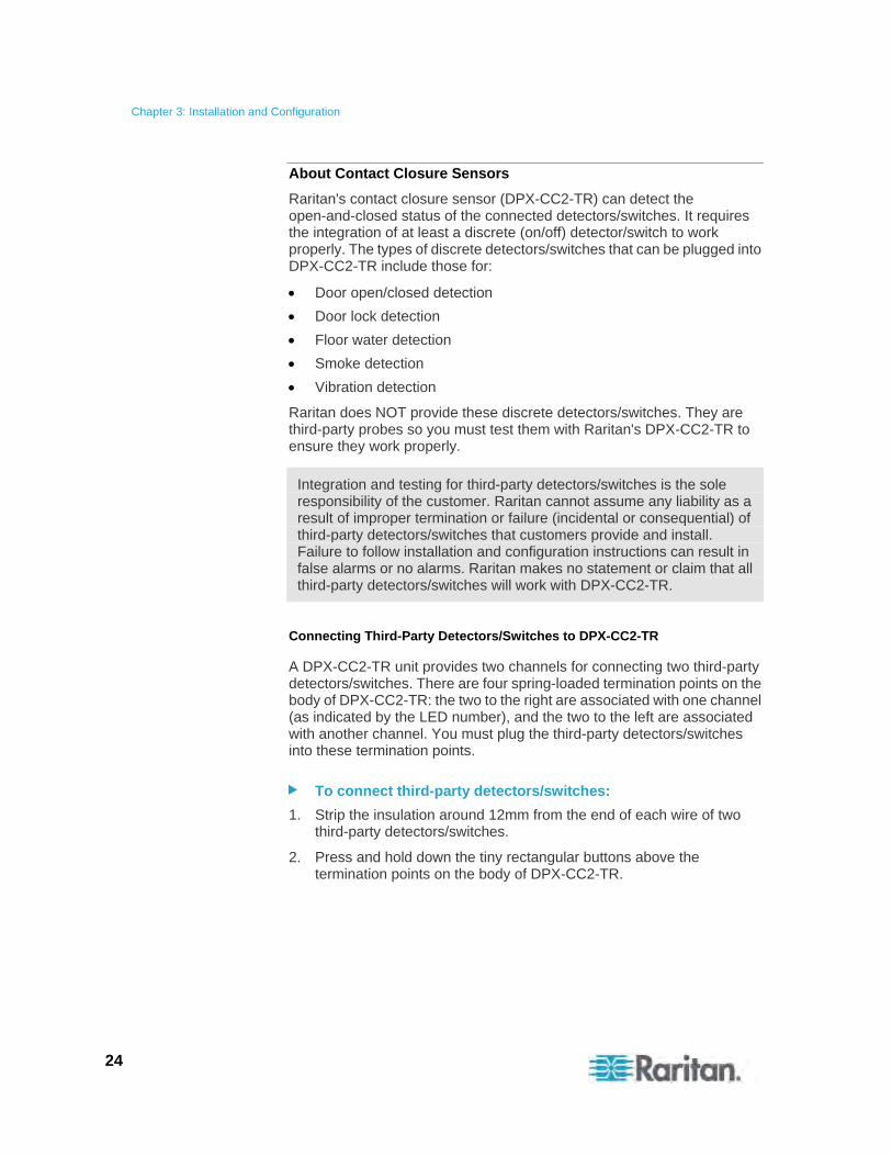
2. Press and hold down the tiny rectangular buttons above the termination points on the body of DPX-CC2-TR.
Chapter 3: Installation and Configuration
25
Note: Each button controls the spring of each corresponding termination point.
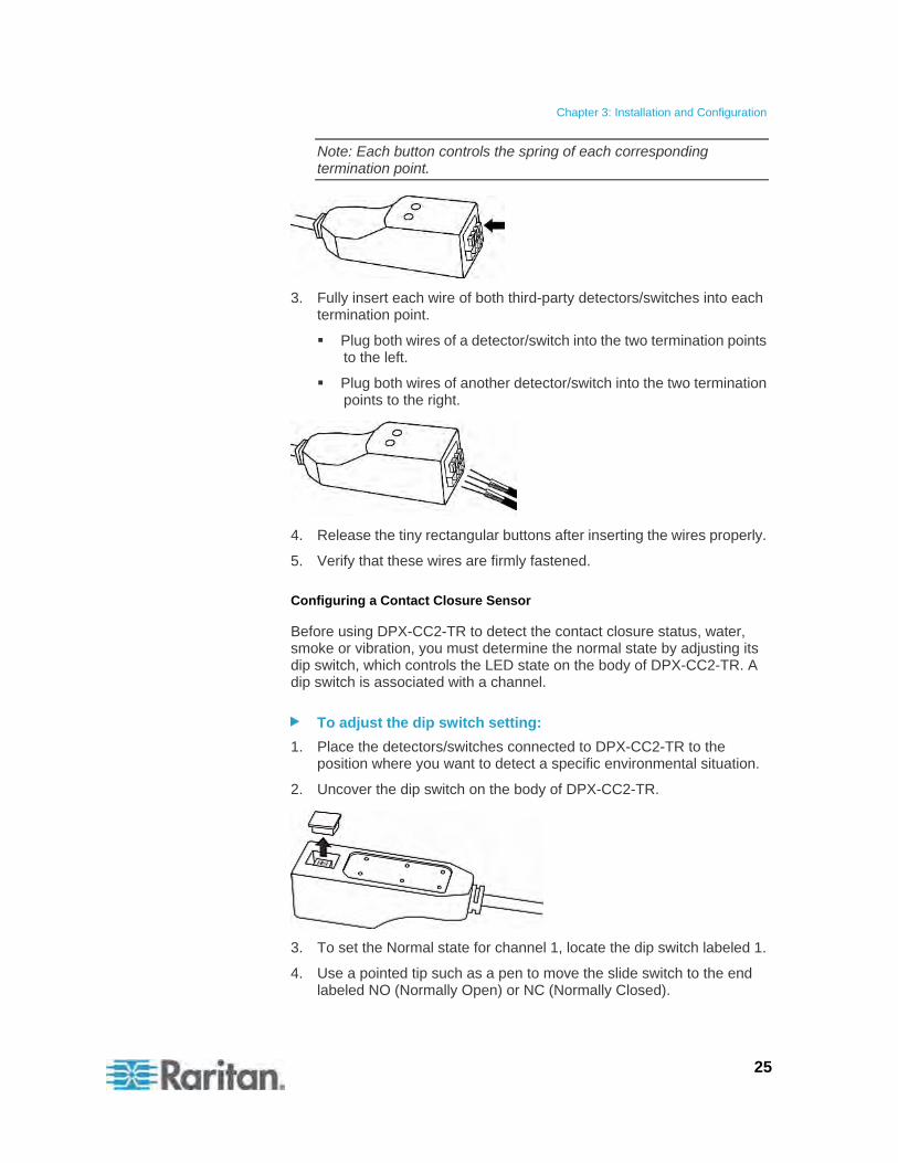
3. Fully insert each wire of both third-party detectors/switches into each termination point.
Plug both wires of a detector/switch into the two termination points to the left.
Plug both wires of another detector/switch into the two termination points to the right.
4. Release the tiny rectangular buttons after inserting the wires properly.
5. Verify that these wires are firmly fastened.
Configuring a Contact Closure Sensor
Before using DPX-CC2-TR to detect the contact closure status, water, smoke or vibration, you must determine the normal state by adjusting its dip switch, which controls the LED state on the body of DPX-CC2-TR. A dip switch is associated with a channel.
To adjust the dip switch setting:
1. Place the detectors/switches connected to DPX-CC2-TR to the position where you want to detect a specific environmental situation.
2. Uncover the dip switch on the body of DPX-CC2-TR.
3. To set the Normal state for channel 1, locate the dip switch labeled 1.
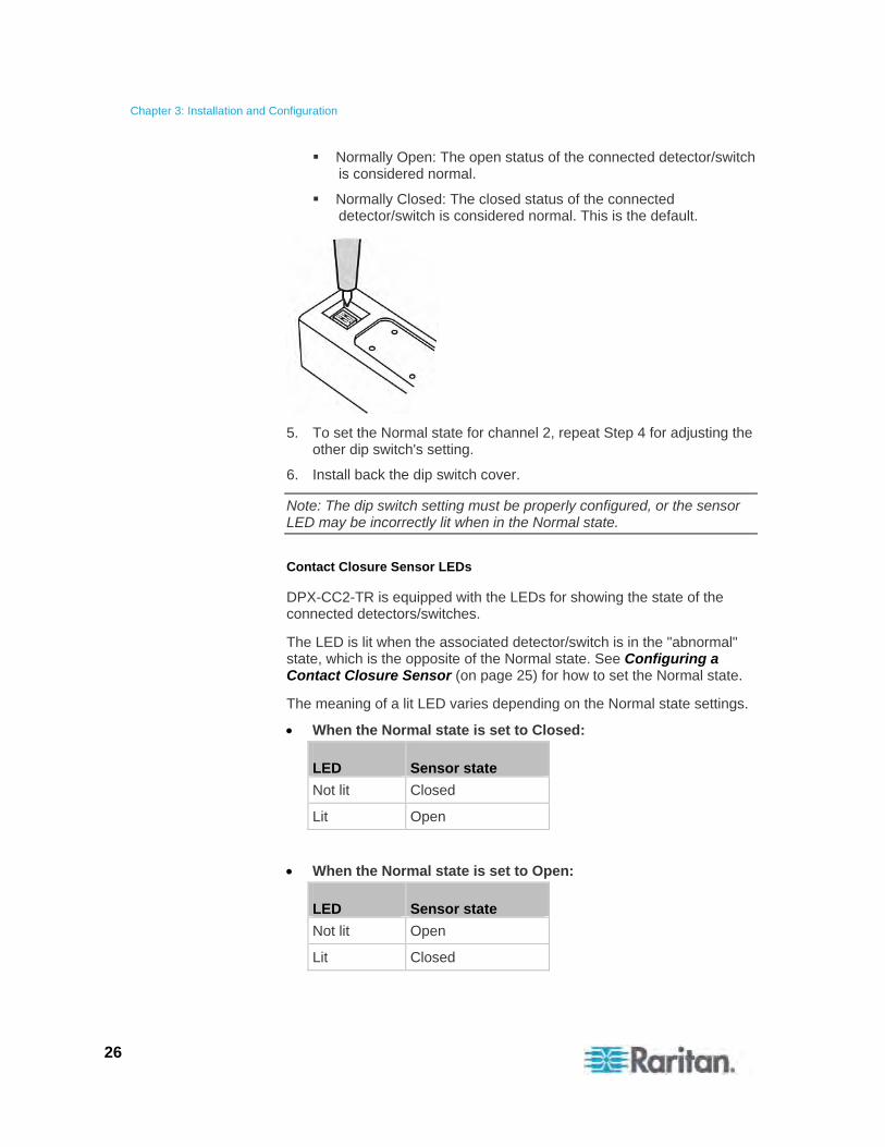
4. Use a pointed tip such as a pen to move the slide switch to the end labeled NO (Normally Open) or NC (Normally Closed).
Chapter 3: Installation and Configuration
26
Normally Open: The open status of the connected detector/switch is considered normal.
Normally Closed: The closed status of the connected detector/switch is considered normal. This is the default.
5. To set the Normal state for channel 2, repeat Step 4 for adjusting the other dip switch's setting.
6. Install back the dip switch cover.
Note: The dip switch setting must be properly configured, or the sensor LED may be incorrectly lit when in the Normal state.
Contact Closure Sensor LEDs
DPX-CC2-TR is equipped with the LEDs for showing the state of the connected detectors/switches.
The LED is lit when the associated detector/switch is in the "abnormal" state, which is the opposite of the Normal state. See Configuring a Contact Closure Sensor (on page 25) for how to set the Normal state.
The meaning of a lit LED varies depending on the Normal state settings.
When the Normal state is set to Closed:
LED Sensor state
Not lit Closed
Lit Open
When the Normal state is set to Open:
LED Sensor state
Not lit Open
Lit Closed

Chapter 3: Installation and Configuration
27
How to Connect Differential Air Pressure Sensors
You can have a Raritan differential air pressure sensor connected to the Raritan PXE device if the differential air pressure data is desired.
With this sensor, the temperature around the sensor can be also detected through a temperature sensor implemented inside it.
Multiple differential air pressure sensors can be cascaded.
To connect a differential air pressure sensor:
1. Plug one end of a Raritan-provided phone cable to the SENSOR port of the Raritan PXE device.
2. Plug the other end of this phone cable to the IN port of the differential air pressure sensor.
3. To connect additional Raritan differential air pressure sensors, do the following:
a. Plug one end of a Raritan-provided phone cable to the OUT port of the previous differential air pressure sensor.
b. Plug the other end of this phone cable to the IN port of the newly-added differential air pressure sensor.
c. Repeat Steps a to b to cascade more differential air pressure sensors. Note that a PDU supports a maximum of 16 environmental sensors only.
The Raritan PXE device
The Raritan differential air pressure sensor
28
This chapter explains how to use the Raritan PXE device. It describes the LEDs and ports on the PDU, and explains how to use the LED display panel. It also explains how the circuit breaker (overcurrent protector) works and when the beeper sounds.
In This Chapter
Panel Components ..................................................................................28 Circuit Breakers .......................................................................................33 Beeper .....................................................................................................35
Panel Components
The Raritan PXE comes in Zero U, 1U, and 2U sizes. All types of models come with the following components on the outer panels.
Power cord
Outlets
Connection ports
LED display
Reset button
Power Cord
Most of Raritan PDUs come with an installed power cord, which is ready to be plugged into an appropriate receptacle for receiving electricity. Such devices cannot be rewired by the user.
Connect each Raritan PXE device to an appropriately rated branch circuit. See the label or nameplate affixed to your Raritan PXE device for appropriate input ratings or range of ratings.
There is no power switch on the Raritan PXE device. To power cycle the PDU, unplug it from the branch circuit, wait 10 seconds and then plug it back in.
Outlets
The total number of outlets varies from model to model.
These PDUs are not outlet-switching capable models so all outlets are always in the ON state.
Outlet LEDs are not available.
Chapter 4 Using the PDU

Chapter 4: Using the PDU
29
Connection Ports
There are 4 ports located on the front panel of the PDU as shown below.
The table below explains the function of each port.
Port Used for...
USB-B Establishing a USB connection between a computer and the Raritan PXE device.
RS-485 Reserved for a future release.
SENSOR Connection to Raritan's environmental sensors.
For Zero U products, a sensor hub is required if you want to connect more than one environmental sensor.
ETHERNET Connecting the Raritan PXE device to your company's network:
Connect a standard Cat5e/6 UTP cable to this port and connect the other end to your network. This connection is necessary to administer or access the Raritan PXE device remotely using the web interface.
There are two small LEDs adjacent to the port:
Green indicates a physical link and activity.
Yellow indicates communications at 10/100 BaseT speeds.

Chapter 4: Using the PDU
30
LED Display
The LED display is located on the side where outlets are available.
These diagrams show the LED display on different types of PDUs. Note that the LED display might slightly vary according to the PDU you purchased.
The LED display consists of:
A row displaying three digits
A row displaying two digits
Up and Down buttons
Five LEDs for measurement units
Note: When a Raritan PXE device powers up, it proceeds with the power-on self test and software loading for a few moments. When the software has completed loading, the LED display illuminates.
Three-Digit Row
The three-digit row shows the readings for the selected component. Values that may appear include:
Active power or unbalanced load of the inlet
Current, voltage, or active power of the selected line
Note: L1 voltage refers to the L1-L2 or L1-N voltage, L2 voltage refers to the L2-L3 or L2-N voltage, and L3 voltage refers to the L3-L1 or L3-N voltage.
The text “FuP,” which indicates that the Firmware uPgrade is being performed

Chapter 4: Using the PDU
31
LEDs for Measurement Units
Five small LED indicators are on the LED display: four measurement units LEDs and one Sensor LED.
The measurement units vary according to the readings that appear in the three-digit row. They are:
Amp (A) for current
Volt (V) for voltage
Kilowatt (kW) for active power
Percentage (%) of the unbalanced load
One of the measurement unit LEDs will be lit to indicate the unit for the value currently shown in the three-digit row.
The Sensor LED is lit only when Raritan PXE detects the physical connection of any environmental sensor.
The five LEDs look similar to this diagram but may slightly vary according to the model you purchased.
Two-Digit Row
The two-digit row shows the number of the currently selected line or inlet. Values that may appear include:
Lx: This indicates the selected line of a single-inlet PDU, where x is the line number. For example, L2 represents Line 2.
Note: For a single-phase model, L1 current represents the Unit Current.
AP: This indicates the selected inlet's active power.
Automatic Mode
When left alone, the LED display cycles through the line readings at intervals of 10 seconds, as available for your Raritan PXE. This is the Automatic Mode.
Chapter 4: Using the PDU
32
Manual Mode
You can press the Up or Down button to enter the Manual Mode so that a particular line or the inlet's active power is selected to show specific readings.
To operate the LED display:
1. Press the Up or Down button until the desired line's number is selected in the two-digit row. Or you can press either button to select the inlet's active power, which is shown as AP.
Pressing the (UP) button moves up one selection.
Pressing the (DOWN) button moves down one selection.
2. When selecting a line, you can press the Up and Down buttons simultaneously to switch between voltage, active power and current readings.
Current of the selected component is shown in the three-digit row. Simultaneously the CURRENT(A) LED is lit. See LEDs for Measurement Units (on page 31).
When the voltage is displayed, the VOLTAGE(V) LED is lit. It is displayed for about five seconds, after which the current reading re-appears.
When the active power is displayed, the POWER(kW) LED is lit. It is displayed for about five seconds, after which the current reading re-appears.
3. When selecting the inlet (AP), it displays the active power reading.
When the active power is displayed, the POWER(kW) LED is lit.
Note: The LED display returns to the Automatic Mode after 20 seconds elapse since the last time any button was pressed.
Chapter 4: Using the PDU
33
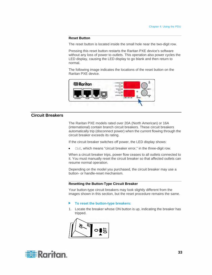
Reset Button
The reset button is located inside the small hole near the two-digit row.
Pressing this reset button restarts the Raritan PXE device's software without any loss of power to outlets. This operation also power cycles the LED display, causing the LED display to go blank and then return to normal.
The following image indicates the locations of the reset button on the Raritan PXE device.
Circuit Breakers
The Raritan PXE models rated over 20A (North American) or 16A (international) contain branch circuit breakers. These circuit breakers automatically trip (disconnect power) when the current flowing through the circuit breaker exceeds its rating.
If the circuit breaker switches off power, the LED display shows:
CbE, which means "circuit breaker error," in the three-digit row.
When a circuit breaker trips, power flow ceases to all outlets connected to it. You must manually reset the circuit breaker so that affected outlets can resume normal operation.
Depending on the model you purchased, the circuit breaker may use a button- or handle-reset mechanism.
Resetting the Button-Type Circuit Breaker
Your button-type circuit breakers may look slightly different from the images shown in this section, but the reset procedure remains the same.
To reset the button-type breakers:
1. Locate the breaker whose ON button is up, indicating the breaker has tripped.
Chapter 4: Using the PDU
34
2. Examine your Raritan PXE device and the connected equipment to remove or resolve the cause that results in the overload or short circuit. This step is required, or you cannot proceed with the next step.
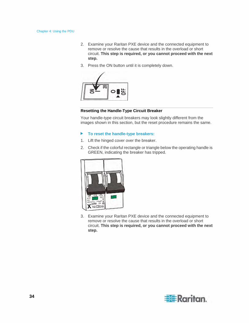
3. Press the ON button until it is completely down.
Resetting the Handle-Type Circuit Breaker
Your handle-type circuit breakers may look slightly different from the images shown in this section, but the reset procedure remains the same.
To reset the handle-type breakers:
1. Lift the hinged cover over the breaker.
2. Check if the colorful rectangle or triangle below the operating handle is GREEN, indicating the breaker has tripped.
3. Examine your Raritan PXE device and the connected equipment to remove or resolve the cause that results in the overload or short circuit. This step is required, or you cannot proceed with the next step.
Chapter 4: Using the PDU
35
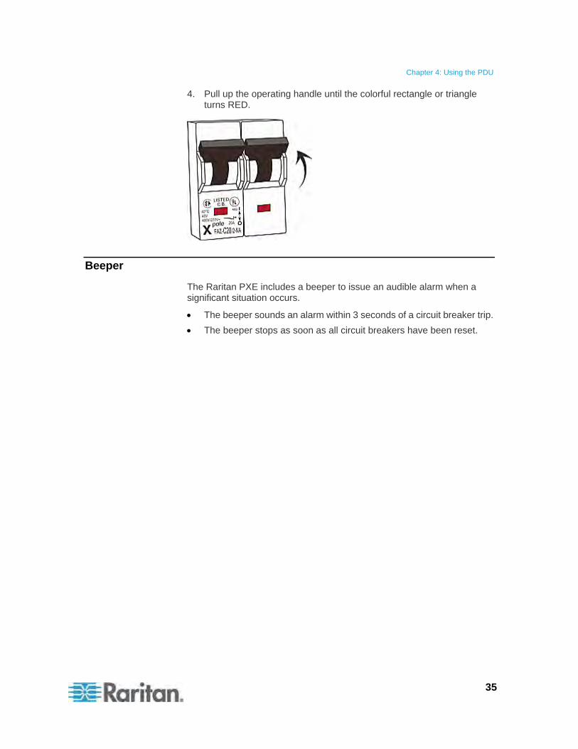
4. Pull up the operating handle until the colorful rectangle or triangle turns RED.
Beeper
The Raritan PXE includes a beeper to issue an audible alarm when a significant situation occurs.
The beeper sounds an alarm within 3 seconds of a circuit breaker trip.
The beeper stops as soon as all circuit breakers have been reset.
36
This chapter explains how to use the web interface to administer a Raritan PXE device.
In This Chapter
Supported Web Browsers........................................................................36 Logging in to the Web Interface ..............................................................37 Logout......................................................................................................39 Introduction to the Web Interface ............................................................40 Viewing the Dashboard ...........................................................................51 Device Management................................................................................51 User Management ...................................................................................68 Setting Up Roles......................................................................................73 Access Security Control ..........................................................................75 Setting Up an SSL Certificate..................................................................87 Setting Up LDAP Authentication .............................................................92 Outlet Management .................................................................................98 Inlet and Circuit Breaker Management....................................................99 Setting Power Thresholds .....................................................................102 Configuring Event Rules........................................................................105 Managing Event Logging.......................................................................115 Viewing Connected Users .....................................................................116 Monitoring Server Accessibility..............................................................117 Environmental Sensors .........................................................................120 Copying Configurations with Bulk Configuration ...................................130 Changing the Measurement Units.........................................................132 Network Diagnostics..............................................................................134 Viewing the Communication Log...........................................................135 Downloading Diagnostic Information.....................................................136 Firmware Upgrade.................................................................................136 Accessing the Help................................................................................139
Supported Web Browsers
The following web browsers can be used to access the Raritan PXE web interface:
Internet Explorer® 7 (IE7) and Internet Explorer® 8 (IE8)
Firefox 3.n.n (where n represents a numeric digit)
Safari, Konqueror
Note: IE6 and Chrome are NOT supported.
Chapter 5 Using the Web Interface
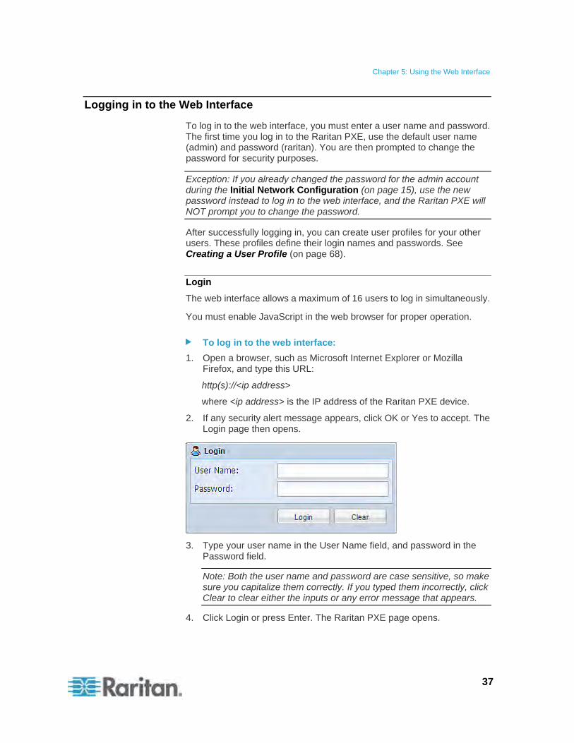
Chapter 5: Using the Web Interface
37
Logging in to the Web Interface
To log in to the web interface, you must enter a user name and password. The first time you log in to the Raritan PXE, use the default user name (admin) and password (raritan). You are then prompted to change the password for security purposes.
Exception: If you already changed the password for the admin account during the Initial Network Configuration (on page 15), use the new password instead to log in to the web interface, and the Raritan PXE will NOT prompt you to change the password.
After successfully logging in, you can create user profiles for your other users. These profiles define their login names and passwords. See Creating a User Profile (on page 68).
Login
The web interface allows a maximum of 16 users to log in simultaneously.
You must enable JavaScript in the web browser for proper operation.
To log in to the web interface:
1. Open a browser, such as Microsoft Internet Explorer or Mozilla Firefox, and type this URL:
http(s)://<ip address>
where <ip address> is the IP address of the Raritan PXE device.
2. If any security alert message appears, click OK or Yes to accept. The Login page then opens.
3. Type your user name in the User Name field, and password in the Password field.
Note: Both the user name and password are case sensitive, so make sure you capitalize them correctly. If you typed them incorrectly, click Clear to clear either the inputs or any error message that appears.
4. Click Login or press Enter. The Raritan PXE page opens.
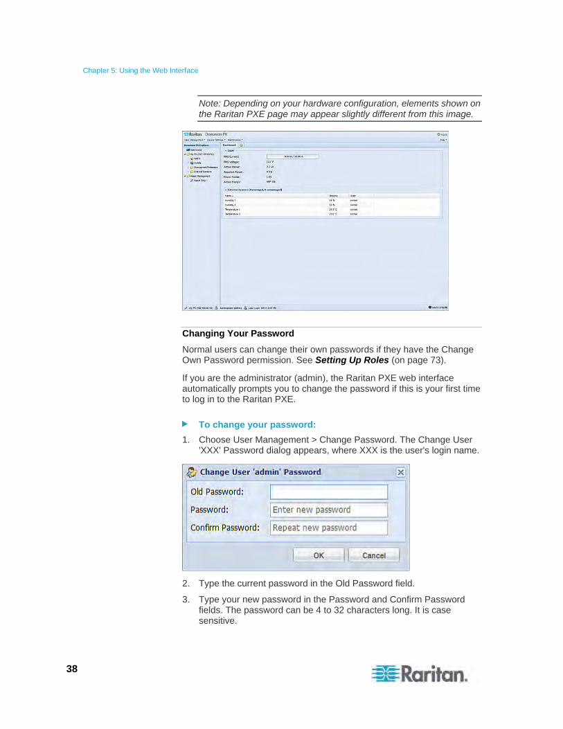
Chapter 5: Using the Web Interface
38
Note: Depending on your hardware configuration, elements shown on the Raritan PXE page may appear slightly different from this image.
Changing Your Password
Normal users can change their own passwords if they have the Change Own Password permission. See Setting Up Roles (on page 73).
If you are the administrator (admin), the Raritan PXE web interface automatically prompts you to change the password if this is your first time to log in to the Raritan PXE.
To change your password:
1. Choose User Management > Change Password. The Change User 'XXX' Password dialog appears, where XXX is the user's login name.
2. Type the current password in the Old Password field.
3. Type your new password in the Password and Confirm Password fields. The password can be 4 to 32 characters long. It is case sensitive.
Chapter 5: Using the Web Interface
39
4. Click OK to save the changes.
Tip: If you have the Administrator Privileges, you can change other users' passwords. See Modifying a User Profile (on page 71).
Logout
After finishing your tasks with the Raritan PXE, you should log out to prevent others from accessing the web interface.
To log out of the web interface:
1. Do one of these:
Click "logout" on the top-right corner of the web interface.
Close the web browser by clicking the Close button ( ) on the top-right corner of the browser.
Close the web browser by choosing File > Close, or File > Exit. The command varies according to the version of the browser you use.
Choose the Refresh command or click the Refresh button on the web browser.
2. Either the login page opens or the browser is closed, depending on your choice in the previous step.
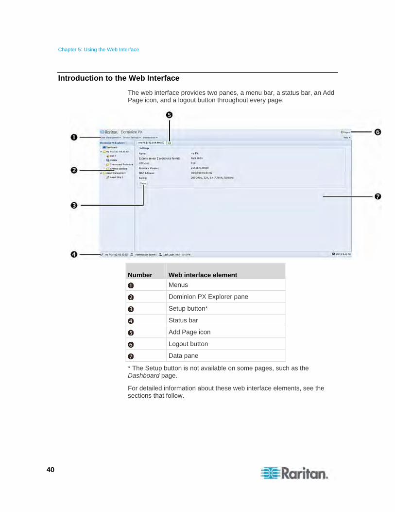
Chapter 5: Using the Web Interface
40
Introduction to the Web Interface
The web interface provides two panes, a menu bar, a status bar, an Add Page icon, and a logout button throughout every page.
Number Web interface element
Menus
Dominion PX Explorer pane
Setup button*
Status bar
Add Page icon
Logout button
Data pane
* The Setup button is not available on some pages, such as the Dashboard page.
For detailed information about these web interface elements, see the sections that follow.
Chapter 5: Using the Web Interface
41
Menus
There is a menu bar across the top of the page. You can click any menu to select the desired menu item from the drop-down list.
Four menus are available for managing different tasks or showing information.
User Management contains menu items for managing user profiles, permissions (roles), and password.
Device Settings deals with device-related settings, such as the device name, network settings, security settings, and system time.
Maintenance provides tools that are helpful for maintaining the Raritan PXE device, such as the event log, hardware information, firmware upgrade and so on.
Help displays information regarding the firmware and all open source packages embedded on the Raritan PXE device. In addition, you can access the user guide from this menu.
Dominion PX Explorer Pane
The hierarchical tree to the left displays the Raritan PXE device you are accessing as well as all physical components embedded on or connected to this PDU, such as inlets, outlets, and environmental sensors. In addition, an icon named Dashboard is available for displaying the PDU summary information.
The tree structure comprises three hierarchical levels.
First level Second level Third level
Dashboard None None
Inlet I1 None
Outlets folder 1 to n**
Overcurrent Protectors folder C1 to Cn**
PDU folder*
External Sensors folder A list of connected environmental sensors
* The PDU folder is named "my PX" by default. The name changes after customizing the device name. See Naming the PDU (on page 53).
** n represents the final number of that component.
To navigate through the tree:
1. To expand any folders, see Expanding the Tree (on page 42).
Chapter 5: Using the Web Interface
42
2. To show any tree item's data, click on that item. See Add Page Icon (on page 45).
Expanding the Tree
The icons representing all components implemented on or connected to the Raritan PXE device are expanded by default. If they are hidden, you may expand the tree manually to show all component icons.
To expand the tree:
1. By default, the PDU folder has been expanded.
Note: The PDU folder is named "my PX" by default. The name changes after customizing the device name. See Naming the PDU (on page 53).
If it is not expanded, click the white arrow prior to the folder icon, or double-click the folder. The arrow then turns into a black, gradient arrow , and icons of components or component groups appear below the PDU folder.
2. To expand any component group at the second level, click the white arrow prior to the folder icon, or double-click the folder.
The arrow then turns into a black, gradient arrow , and icons representing individual components appear below the group folder.
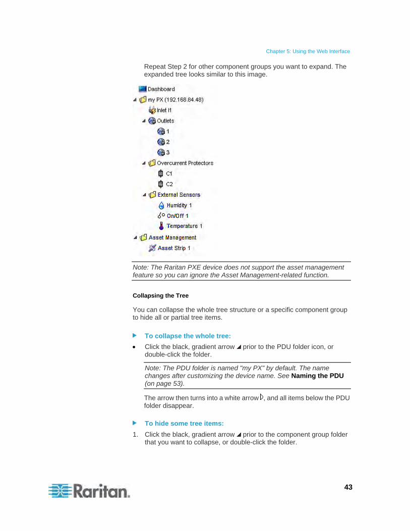
Chapter 5: Using the Web Interface
43
Repeat Step 2 for other component groups you want to expand. The expanded tree looks similar to this image.
Note: The Raritan PXE device does not support the asset management feature so you can ignore the Asset Management-related function.
Collapsing the Tree
You can collapse the whole tree structure or a specific component group to hide all or partial tree items.
To collapse the whole tree:
Click the black, gradient arrow prior to the PDU folder icon, or double-click the folder.
Note: The PDU folder is named "my PX" by default. The name changes after customizing the device name. See Naming the PDU (on page 53).
The arrow then turns into a white arrow , and all items below the PDU folder disappear.
To hide some tree items:
1. Click the black, gradient arrow prior to the component group folder that you want to collapse, or double-click the folder.

Chapter 5: Using the Web Interface
44
The arrow then turns into a white arrow , and all items below the folder disappear.
2. Repeat Step 1 for other component groups you want to collapse.
Adjusting the Pane
You can change the width of the pane to make the area larger or smaller.
To adjust the pane's width:
1. Move the mouse pointer to the right border of the Dominion PX Explorer pane.
2. When the mouse pointer turns into a two-way arrow, drag the border horizontally to widen or shrink the pane.
Setup Button
The Setup button is available for most tree items. It triggers a setup dialog where you can change settings for the selected tree item.
Status Bar
The status bar shows five pieces of information from left to right.
Device name:
This is the name assigned to the Raritan PXE device. The default is "my PX." See Naming the PDU (on page 53).
IP address:
The numbers enclosed in parentheses is the IP address assigned to the Raritan PXE device. See Initial Network Configuration (on page 15) or Modifying the Network Settings (on page 54).
Tip: The presence of the device name and IP address in the status bar indicates the connection to the Raritan PXE device. If the connection
is lost, it shows " " instead.
Login name:
This is the user name you used to log in to the web interface.
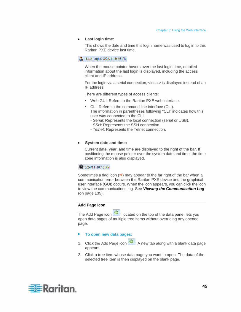
Chapter 5: Using the Web Interface
45
Last login time:
This shows the date and time this login name was used to log in to this Raritan PXE device last time.
When the mouse pointer hovers over the last login time, detailed information about the last login is displayed, including the access client and IP address.
For the login via a serial connection, <local> is displayed instead of an IP address.
There are different types of access clients:
Web GUI: Refers to the Raritan PXE web interface.
CLI: Refers to the command line interface (CLI). The information in parentheses following "CLI" indicates how this user was connected to the CLI. - Serial: Represents the local connection (serial or USB). - SSH: Represents the SSH connection. - Telnet: Represents the Telnet connection.
System date and time:
Current date, year, and time are displayed to the right of the bar. If positioning the mouse pointer over the system date and time, the time zone information is also displayed.
Sometimes a flag icon ( ) may appear to the far right of the bar when a communication error between the Raritan PXE device and the graphical user interface (GUI) occurs. When the icon appears, you can click the icon to view the communications log. See Viewing the Communication Log (on page 135).
Add Page Icon
The Add Page icon , located on the top of the data pane, lets you open data pages of multiple tree items without overriding any opened page.
To open new data pages:
1. Click the Add Page icon . A new tab along with a blank data page appears.
2. Click a tree item whose data page you want to open. The data of the selected tree item is then displayed on the blank page.
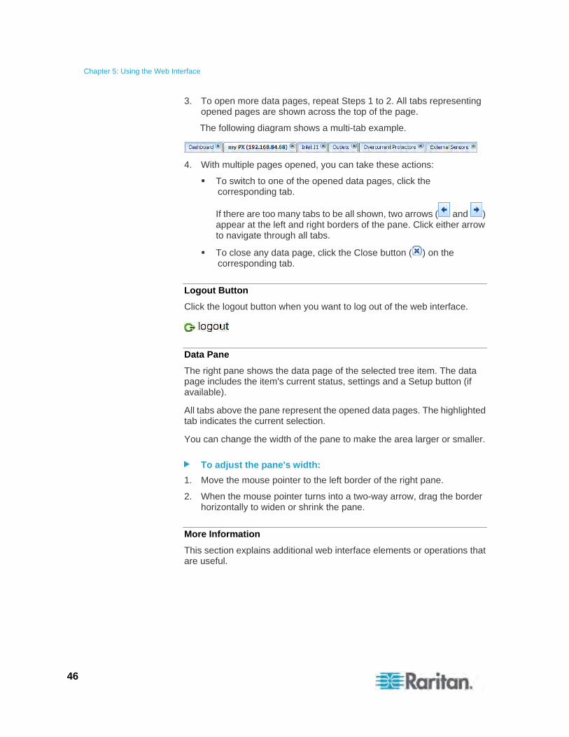
Chapter 5: Using the Web Interface
46
3. To open more data pages, repeat Steps 1 to 2. All tabs representing opened pages are shown across the top of the page.
The following diagram shows a multi-tab example.
4. With multiple pages opened, you can take these actions:
To switch to one of the opened data pages, click the corresponding tab.
If there are too many tabs to be all shown, two arrows ( and ) appear at the left and right borders of the pane. Click either arrow to navigate through all tabs.
To close any data page, click the Close button ( ) on the corresponding tab.
Logout Button
Click the logout button when you want to log out of the web interface.
Data Pane
The right pane shows the data page of the selected tree item. The data page includes the item's current status, settings and a Setup button (if available).
All tabs above the pane represent the opened data pages. The highlighted tab indicates the current selection.
You can change the width of the pane to make the area larger or smaller.
To adjust the pane's width:
1. Move the mouse pointer to the left border of the right pane.
2. When the mouse pointer turns into a two-way arrow, drag the border horizontally to widen or shrink the pane.
More Information
This section explains additional web interface elements or operations that are useful.
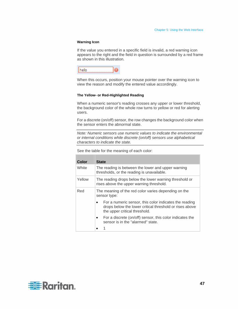
Chapter 5: Using the Web Interface
47
Warning Icon
If the value you entered in a specific field is invalid, a red warning icon appears to the right and the field in question is surrounded by a red frame as shown in this illustration.
When this occurs, position your mouse pointer over the warning icon to view the reason and modify the entered value accordingly.
The Yellow- or Red-Highlighted Reading
When a numeric sensor's reading crosses any upper or lower threshold, the background color of the whole row turns to yellow or red for alerting users.
For a discrete (on/off) sensor, the row changes the background color when the sensor enters the abnormal state.
Note: Numeric sensors use numeric values to indicate the environmental or internal conditions while discrete (on/off) sensors use alphabetical characters to indicate the state.
See the table for the meaning of each color:
Color State
White The reading is between the lower and upper warning thresholds, or the reading is unavailable.
Yellow The reading drops below the lower warning threshold or rises above the upper warning threshold.
Red The meaning of the red color varies depending on the sensor type:
For a numeric sensor, this color indicates the reading drops below the lower critical threshold or rises above the upper critical threshold.
For a discrete (on/off) sensor, this color indicates the sensor is in the "alarmed" state.
1
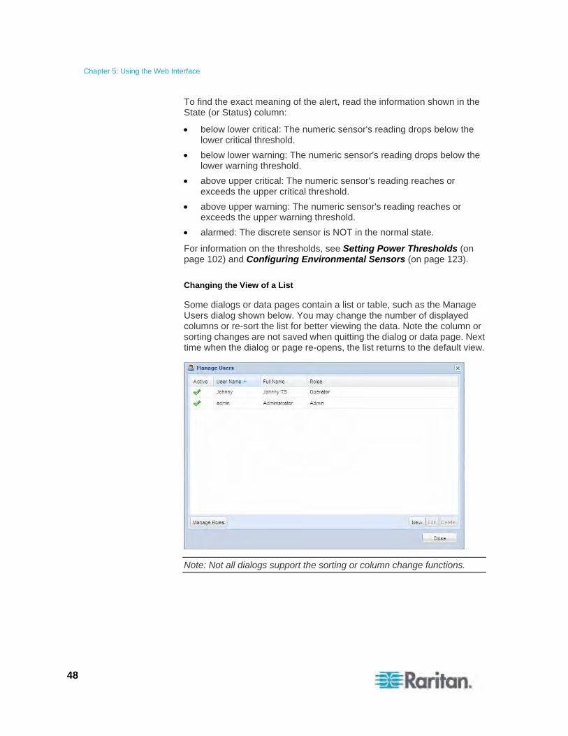
Chapter 5: Using the Web Interface
48
To find the exact meaning of the alert, read the information shown in the State (or Status) column:
below lower critical: The numeric sensor's reading drops below the lower critical threshold.
below lower warning: The numeric sensor's reading drops below the lower warning threshold.
above upper critical: The numeric sensor's reading reaches or exceeds the upper critical threshold.
above upper warning: The numeric sensor's reading reaches or exceeds the upper warning threshold.
alarmed: The discrete sensor is NOT in the normal state.
For information on the thresholds, see Setting Power Thresholds (on page 102) and Configuring Environmental Sensors (on page 123).
Changing the View of a List
Some dialogs or data pages contain a list or table, such as the Manage Users dialog shown below. You may change the number of displayed columns or re-sort the list for better viewing the data. Note the column or sorting changes are not saved when quitting the dialog or data page. Next time when the dialog or page re-opens, the list returns to the default view.
Note: Not all dialogs support the sorting or column change functions.
Chapter 5: Using the Web Interface
49
Changing the Column
You can hide some columns of a list or table, or adjust a specific column's width.
To change displayed columns:
1. Hover your mouse pointer over any column header. A black triangle
appears to the far right of this column header.
2. Click the black triangle, and a drop-down menu appears.
3. Point to Columns. A submenu showing all columns appears.
4. Click any column you want to deselect or select.
To hide a column, have its checkbox deselected.
To show a column, have its checkbox selected.
To change the column width:
1. Hover the mouse pointer to the right border of the desired column.
2. When the mouse pointer turns to a two-way arrow, drag the border horizontally to widen or shrink the column.
Changing the Sorting
By default, a list or table is sorted against the first column in the ascending order. You can re-sort the list in a reverse order or against a different column.
To re-sort the list by doing either of the following:
Click the column header against which you want to sort the list.
a. The first click sorts the list in the ascending order, indicated by a blue upward-pointing triangle .
b. The second click reverses the sorting to the descending order, indicated by a blue downward-pointing triangle .
Select a sorting command from the column menu.
a. Hover your mouse pointer over the column header against which
you want to sort the list. A black triangle appears to the far right of this column header.
b. Click the black triangle, and a drop-down menu appears.
c. Select Sort Ascending or Sort Descending.
The newly selected column header is marked with the upward- or downward-pointing triangle.
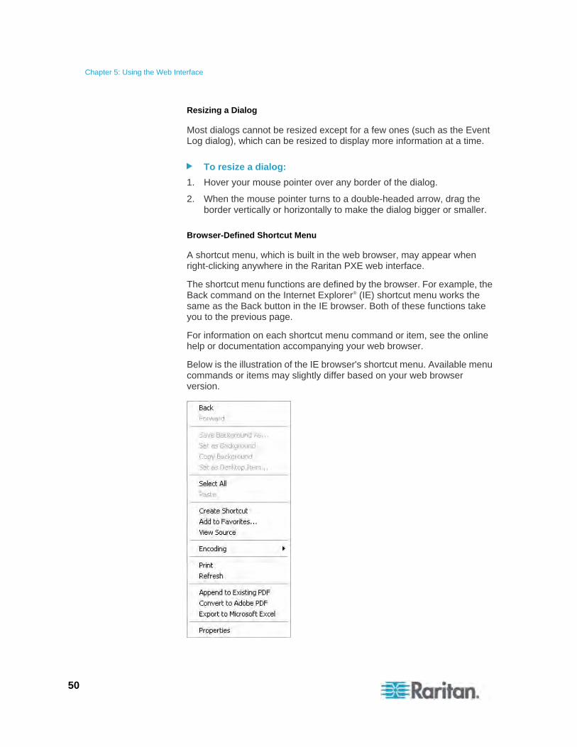
Chapter 5: Using the Web Interface
50
Resizing a Dialog
Most dialogs cannot be resized except for a few ones (such as the Event Log dialog), which can be resized to display more information at a time.
To resize a dialog:
1. Hover your mouse pointer over any border of the dialog.
2. When the mouse pointer turns to a double-headed arrow, drag the border vertically or horizontally to make the dialog bigger or smaller.
Browser-Defined Shortcut Menu
A shortcut menu, which is built in the web browser, may appear when right-clicking anywhere in the Raritan PXE web interface.
The shortcut menu functions are defined by the browser. For example, the Back command on the Internet Explorer® (IE) shortcut menu works the same as the Back button in the IE browser. Both of these functions take you to the previous page.
For information on each shortcut menu command or item, see the online help or documentation accompanying your web browser.
Below is the illustration of the IE browser's shortcut menu. Available menu commands or items may slightly differ based on your web browser version.
Chapter 5: Using the Web Interface
51
Viewing the Dashboard
When you log in to the web interface, the Dashboard page is displayed by default. This page provides an overview of the Raritan PXE device's status.
The page is divided into various sections according to the component type, such as inlet and external sensors.
Note: If a sensor reading row is colored, it means the sensor reading already crosses one of the thresholds. See The Yellow- or Red-Highlighted Reading (on page 47).
After clicking any other icon in the hierarchical tree, the Dashboard page is overridden. To return to the Dashboard page, click the Dashboard icon.
When the Dashboard page is opened, you can do the following to uncover or hide specific data.
To collapse any section:
1. Locate the section you want to collapse.
2. Click the upward arrow prior to the section title. The data specific to the section is hidden.
To expand a collapsed section:
1. Locate the section you want to expand.
2. Click the downward arrow prior to the section title. The data specific to the section appears.
Device Management
Using the web interface, you can retrieve basic hardware and software information, give the Raritan PXE a new device name, set the system date and time, and modify network settings that were entered during the initial configuration process.
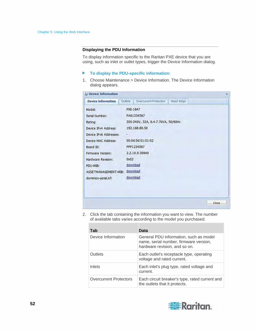
Chapter 5: Using the Web Interface
52
Displaying the PDU Information
To display information specific to the Raritan PXE device that you are using, such as inlet or outlet types, trigger the Device Information dialog.
To display the PDU-specific information:
1. Choose Maintenance > Device Information. The Device Information dialog appears.
2. Click the tab containing the information you want to view. The number of available tabs varies according to the model you purchased.
Tab Data
Device Information General PDU information, such as model name, serial number, firmware version, hardware revision, and so on.
Outlets Each outlet's receptacle type, operating voltage and rated current.
Inlets Each inlet's plug type, rated voltage and current.
Overcurrent Protectors Each circuit breaker's type, rated current and the outlets that it protects.
Chapter 5: Using the Web Interface
53
Tab Data
Controllers Each inlet or outlet controller's serial number, firmware and hardware version.
Note: An outlet's operating voltage is derived from the inlet's rated voltage. The result of this calculation is rounded off mathematically to the nearest integer in volt. For example, if the calculation for the minimum voltage is 380/sqrt(3)=219.39 , the web interface displays 219 V.
3. Enlarge the dialog if necessary. See Resizing a Dialog (on page 50).
4. You can re-sort the list or change the columns displayed. See Changing the View of a List (on page 48).
5. Click Close to quit the dialog.
Tip: The firmware version is also available by clicking the PDU folder in the Dominion PX Explorer pane.
Naming the PDU
The default name for Raritan PXE is my PX. You may give it a unique device name.
To change the device name:
1. Click the PDU folder.
Note: The PDU folder is named "my PX" by default. The name changes after customizing the device name. See Naming the PDU (on page 53).
2. Click Setup in the Settings section. The Pdu Setup dialog appears.
3. Type a new name in the Device Name field.
4. Click OK to save the changes.
Modifying the Network Configuration
The network settings you can change via the web interface include wired, wireless, IPv4 and/or IPv6 settings.
Chapter 5: Using the Web Interface
54
Modifying the Network Interface Settings
The Raritan PXE device only supports the wired networking mode. The wireless networking mode is NOT supported.
The LAN interface speed and duplex mode were set during the installation and configuration process. See Initial Network Configuration (on page 15).
By default, the LAN speed and duplex mode are set to "Auto" (automatic), which works in nearly all scenarios. You can change them if there are special local requirements.
To modify the network interface settings:
1. Choose Device Settings > Network. The Network Configuration dialog appears.
2. The Interface Settings tab should have been selected. If not, click the Interface Settings tab.
3. In the Network Interface field, click the drop-down arrow, and select Wired from the list.
4. To change the LAN speed, click the drop-down arrow in the Speed field and select an option from the list.
Auto: System determines the optimum LAN speed through auto-negotiation.
10 Mbit/s: The LAN speed is always 10 Mbps.
100 Mbit/s: The LAN speed is always 100 Mbps.
5. To change the duplex mode, click the drop-down arrow in the Duplex field and select an option from the list.
Auto: The Raritan PXE selects the optimum transmission mode through auto-negotiation.
Full: Data is transmitted in both directions simultaneously.
Half: Data is transmitted in one direction (to or from the Raritan PXE device) at a time.
6. Click OK to save the changes.
Tip: You can check the LAN status in the Current State field, including the speed and duplex mode.
Modifying the Network Settings
The Raritan PXE was configured for network connectivity during the installation and configuration process. See Configuring the Raritan PXE (on page 12). If necessary, you can modify any network settings using the web interface.
Chapter 5: Using the Web Interface
55
Selecting the Internet Protocol
The Raritan PXE device supports two types of Internet protocols -- IPv4 and IPv6. You can enable either or both Internet protocols. After enabling the desired Internet protocol(s), all but not limited to the following protocols will be compliant with the enabled Internet protocol(s):
LDAP
NTP
SMTP
SSH
Telnet
FTP
SSL
SNMP
SysLog
To select the appropriate Internet Protocol:
1. Choose Device Settings > Network. The Network Configuration dialog appears.
2. Click the IP Protocol tab.
3. Select one checkbox according to the Internet protocol(s) you want to enable:
IPv4 only: Enables IPv4 only on all interfaces. This is the default.
IPv6 only: Enables IPv6 only on all interfaces.
IPv4 and IPv6: Enables both IPv4 and IPv6 on all interfaces.
4. If you selected the "IPv4 and IPv6" checkbox in the previous step, you must determine which IP address is used when the DNS resolver returns both of IPv4 and IPv6 addresses.
IPv4 Address: Use the IPv4 addresses returned by the DNS server.
IPv6 Address: Use the IPv6 addresses returned by the DNS server.
5. Click OK to save the changes.
Modifying the IPv4 Settings
You must enable the IPv4 protocol before you can modify the IPv4 network settings. See Selecting the Internet Protocol (on page 55).
To modify the IPv4 settings:
1. Choose Device Settings > Network. The Network Configuration dialog appears.

Chapter 5: Using the Web Interface
56
2. Click the IPv4 Configuration tab.
3. In the IP Auto Configuration field, click the drop-down arrow, and select the desired option from the list.
Option Description
DHCP To auto-configure the Raritan PXE, select DHCP.
With DHCP selected, you can enter a preferred DHCP host name, which is optional. Type the host name in the Preferred Hostname field.
The host name:
Consists of alphanumeric characters and/or hyphens
Cannot begin or end with a hyphen
Cannot contain more than 63 characters
Cannot contain punctuation marks, spaces, and other symbols
Select the "Specify DNS server manually" checkbox if necessary. Then type the address of the primary DNS server in the Primary DNS Server field. The secondary DNS server and DNS suffix are optional.
Static To manually assign an IP address, select Static, and enter the following information in the corresponding fields:
IP address
Netmask
Gateway
Primary DNS server
Secondary DNS server (optional)
DNS Suffix (optional)
4. Click OK to save the changes.
Note: The Raritan PXE supports a maximum of 3 DNS servers. If two IPv4 DNS servers and two IPv6 DNS servers are available, the Raritan PXE only uses the primary IPv4 and IPv6 DNS servers.

Chapter 5: Using the Web Interface
57
Modifying the IPv6 Settings
You must enable the IPv6 protocol before you can modify the IPv6 network settings. See Selecting the Internet Protocol (on page 55).
To modify the IPv6 settings:
1. Choose Device Settings > Network. The Network Configuration dialog appears.
2. Click the IPv6 Configuration tab.
3. In the IP Auto Configuration field, click the drop-down arrow, and select the desired option from the list.
Option Description
Automatic To auto-configure Raritan PXE, select Automatic.
With this option selected, you can enter a preferred host name, which is optional. Type the host name in the Preferred Hostname field.
The host name:
Consists of alphanumeric characters and/or hyphens
Cannot begin or end with a hyphen
Cannot contain more than 63 characters
Cannot contain punctuation marks, spaces, and other symbols
Select the "Specify DNS server manually" checkbox if necessary. Then type the address of the primary DNS server in the Primary DNS Server field. The secondary DNS server and DNS suffix are optional.
Static To manually assign an IP address, select Static, and enter the following information in the corresponding fields:
IP address
Gateway
Primary DNS server
Secondary DNS server (optional)
DNS Suffix (optional)
4. Click OK to save the changes.
Note: The Raritan PXE supports a maximum of 3 DNS servers. If two IPv4 DNS servers and two IPv6 DNS servers are available, the Raritan PXE only uses the primary IPv4 and IPv6 DNS servers.

Chapter 5: Using the Web Interface
58
Role of a DNS Server
As Internet communications are carried out on the basis of IP addresses, appropriate DNS server settings are required for mapping domain names (host names) to corresponding IP addresses, or the Raritan PXE may fail to connect to the given host.
Therefore, DNS server settings are important for LDAP authentication. With appropriate DNS settings, the Raritan PXE can resolve the LDAP server's name to an IP address for establishing a connection. If the SSL encryption is enabled, the DNS server settings become critical since only fully qualified domain name can be used for specifying the LDAP server.
For information on LDAP authentication, see Setting Up LDAP Authentication (on page 92).
Modifying the Network Service Settings
The Raritan PXE supports these network communication services: HTTPS, HTTP, Telnet and SSH.
HTTPS and HTTP enable the access to the web interface, and Telnet and SSH enable the access to the command line interface (see "Using the Command Line Interface" on page 148).
By default, SSH is enabled, Telnet is disabled, and all TCP ports for supported services are set to standard ports. You can change default settings if necessary.
Note: Telnet access is disabled by default because it communicates openly and is thus insecure.
In addition, the Raritan PXE also supports the SNMP protocol.
Changing the HTTP(S) Settings
HTTPS uses Secure Sockets Layer (SSL) technology to encrypt all traffic to and from the Raritan PXE device so it is a more secure protocol than HTTP.
By default, any access to the Raritan PXE device via HTTP is automatically redirected to HTTPS. See Forcing HTTPS Encryption (on page 76).
To change the HTTP or HTTPS port settings:
1. Choose Device Settings > Network Services > HTTP. The HTTP Settings dialog appears.
2. To use a different port for HTTP or HTTPS, type a new port number in the corresponding field. Valid range is 1 to 65535.
Warning: Different network services cannot share the same TCP port.
Chapter 5: Using the Web Interface
59
3. Click OK to save the changes.
Changing the SSH Settings
You can enable or disable the SSH access to the command line interface, or change the default TCP port for the SSH service. In addition, you can decide to log in using either the password or the public key over the SSH connection.
To change the SSH service settings:
1. Choose Device Settings > Network Services > SSH. The SSH Settings dialog appears.
2. To use a different port, type a new port number in the field. Valid range is 1 to 65535.
3. To enable the SSH application, select the Enable SSH Access checkbox. To disable it, deselect the checkbox.
4. To select a different authentication method, select one of the checkboxes.
Allow password authentication only: Enables the password-based login only.
Allow public key authentication only: Enables the public key-based login only.
Allow password and public key authentication: Enables both the password- and public key-based login. This is the default.
5. Click OK to save the changes.
If the public key authentication is selected, you must type a valid SSH public key for each user profile to log in over the SSH connection. See Creating a User Profile (on page 68).
Changing the Telnet Settings
You can enable or disable the Telnet access to the command line interface, or change the default TCP port for the Telnet service.
To change the Telnet service settings:
1. Choose Device Settings > Network Services > Telnet. The Telnet Settings dialog appears.
2. To use a different port, type a new port number in the field. Valid range is 1 to 65535.
3. To enable the Telnet application, select the Enable Telnet Access checkbox. To disable it, deselect the checkbox.
4. Click OK to save the changes.
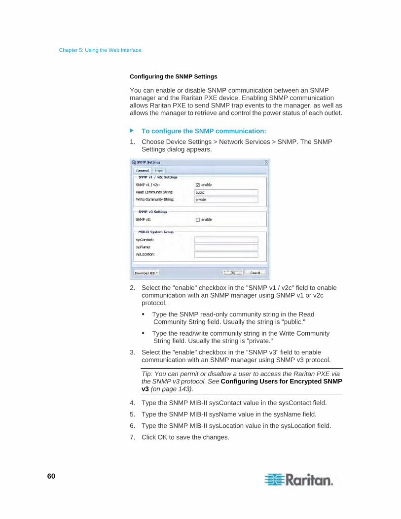
Chapter 5: Using the Web Interface
60
Configuring the SNMP Settings
You can enable or disable SNMP communication between an SNMP manager and the Raritan PXE device. Enabling SNMP communication allows Raritan PXE to send SNMP trap events to the manager, as well as allows the manager to retrieve and control the power status of each outlet.
To configure the SNMP communication:
1. Choose Device Settings > Network Services > SNMP. The SNMP Settings dialog appears.
2. Select the "enable" checkbox in the "SNMP v1 / v2c" field to enable communication with an SNMP manager using SNMP v1 or v2c protocol.
Type the SNMP read-only community string in the Read Community String field. Usually the string is "public."
Type the read/write community string in the Write Community String field. Usually the string is "private."
3. Select the "enable" checkbox in the "SNMP v3" field to enable communication with an SNMP manager using SNMP v3 protocol.
Tip: You can permit or disallow a user to access the Raritan PXE via the SNMP v3 protocol. See Configuring Users for Encrypted SNMP v3 (on page 143).
4. Type the SNMP MIB-II sysContact value in the sysContact field.
5. Type the SNMP MIB-II sysName value in the sysName field.
6. Type the SNMP MIB-II sysLocation value in the sysLocation field.
7. Click OK to save the changes.
Chapter 5: Using the Web Interface
61
Important: You must download the SNMP MIB for your Raritan PXE to use with your SNMP manager. Click Download MIB in this dialog to download the desired MIB file. For more details, see Downloading SNMP MIB (on page 145).
To configure SNMP managers:
1. Choose Device Settings > Network Services > SNMP. The SNMP Settings dialog appears.
2. Click the Traps tab.
3. Select the Enabled checkbox in the "System Snmp Trap Event Rule" field.
4. Specify SNMP managers (destinations) by doing the following:
a. You can specify up to 3 SNMP managers in the Host x fields, where x is a number between 1 and 3.
b. Specify a port number for each SNMP manager in the Port x fields, where x is a number between 1 and 3.
c. Specify a community string for each SNMP manager in the Community x fields, where x is a number between 1 and 3.
5. Click OK to save the changes.
Tip: The SNMP manager settings can be also set in the Event Rule Settings dialog. See Modifying an Action (on page 114).
Setting the Date and Time
You can set the internal clock on the Raritan PXE device manually, or link to a Network Time Protocol (NTP) server and let it set the date and time for the Raritan PXE.
To set the date and time:
1. Choose Device Settings > Date/Time. The Configure Date/Time Settings dialog appears.
2. In the Time Zone field, click the drop-down arrow, and select your time zone from the list.
3. If the daylight saving time applies to your time zone, verify the Automatic Daylight Saving Time Adjustment checkbox is selected.
If the daylight saving time rules are not available for the selected time zone, the checkbox is not configurable.
4. Choose one of the methods to set the date and time:
Chapter 5: Using the Web Interface
62
To customize the date and time, select the User Specified Time radio button, and then enter the date and time in appropriate fields. Use the yyyy-mm-dd format for the date and the hh:mm:ss format for the time.
To set the date, delete existing numbers in the Date field and type new ones, or click the calendar icon to select a date. See How to Use the Calendar (on page 63) for details.
The time is measured in 24-hour format so enter 13 for 1:00pm, 14 for 2:00pm, and so on. You can enter the time by deleting existing numbers and typing new ones in the hour,
minute and second fields, or clicking the arrows to adjust each number.
To let an NTP server set the date and time, select the "Synchronize with NTP Server" radio button. There are two ways to assign the NTP servers.
To use the DHCP-assigned NTP servers, make sure the "Always use the servers below and ignore DHCP-provided servers" checkbox is deselected. This method is usable only when either IPv4 or IPv6 DHCP is enabled.
To use the NTP servers that are manually specified, select the "Always use the servers below and ignore DHCP-provided servers" checkbox, and specify the primary NTP server in the First Time Server field. A secondary NTP server is optional.
Note: If the Raritan PXE device's IP address is assigned through IPv4 or IPv6 DHCP, the NTP servers can be automatically discovered. When this occurs, the data you entered in the fields of First and Second Time Server will be overridden.
5. Click OK to save the changes.
Important: If you are using Raritan's Power IQ to manage the Raritan PXE, you must configure Power IQ and the Raritan PXE to have the same date/time settings.
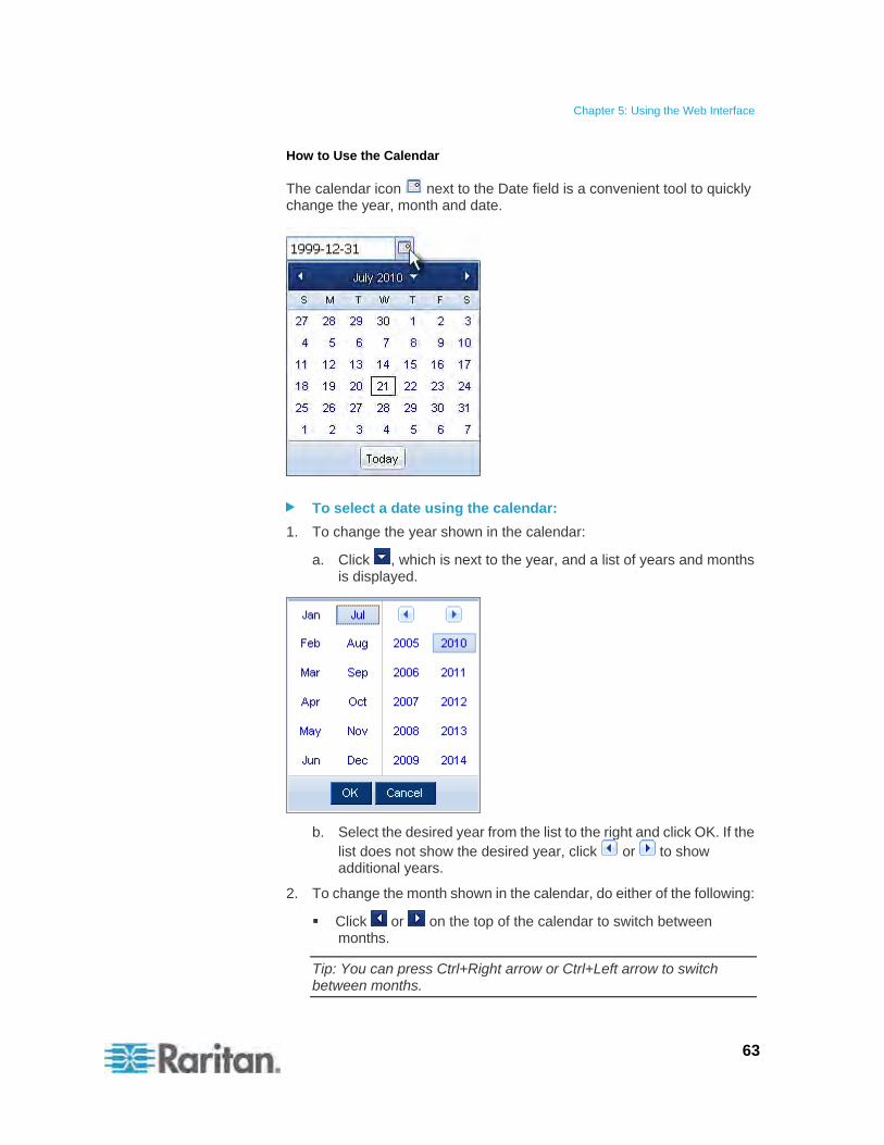
Chapter 5: Using the Web Interface
63
How to Use the Calendar
The calendar icon next to the Date field is a convenient tool to quickly change the year, month and date.
To select a date using the calendar:
1. To change the year shown in the calendar:
a. Click , which is next to the year, and a list of years and months is displayed.
b. Select the desired year from the list to the right and click OK. If the list does not show the desired year, click or to show additional years.
2. To change the month shown in the calendar, do either of the following:
Click or on the top of the calendar to switch between months.
Tip: You can press Ctrl+Right arrow or Ctrl+Left arrow to switch between months.
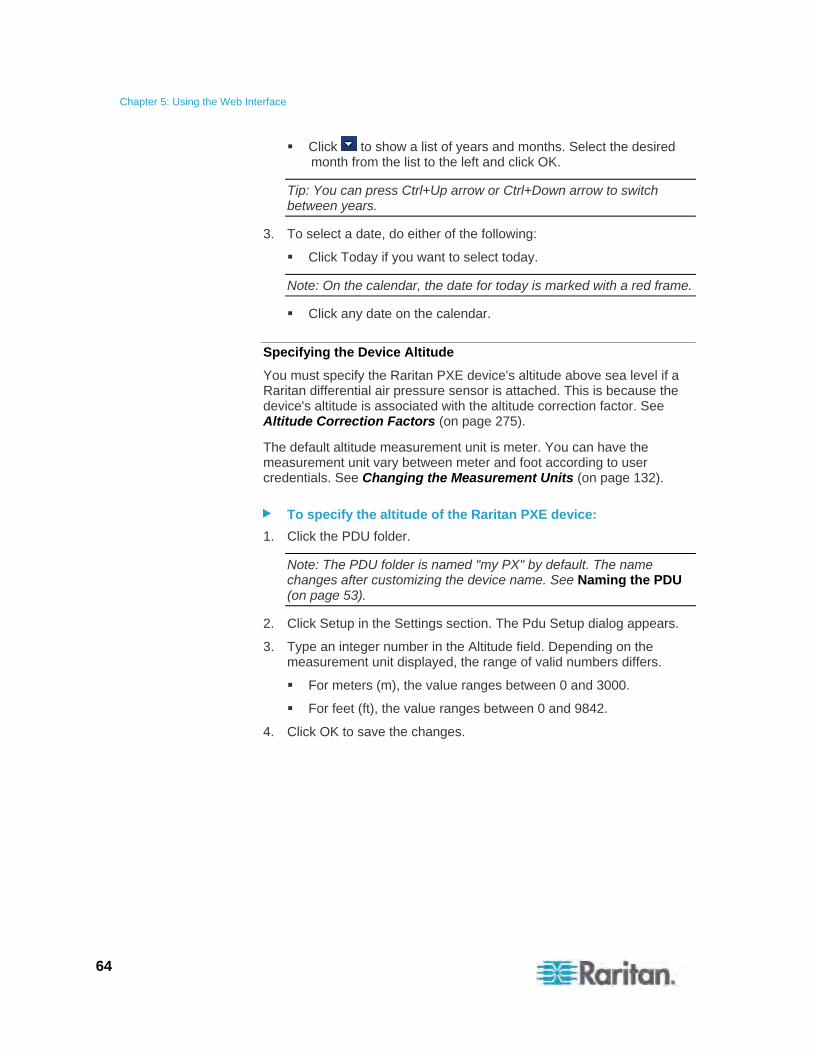
Chapter 5: Using the Web Interface
64
Click to show a list of years and months. Select the desired month from the list to the left and click OK.
Tip: You can press Ctrl+Up arrow or Ctrl+Down arrow to switch between years.
3. To select a date, do either of the following:
Click Today if you want to select today.
Note: On the calendar, the date for today is marked with a red frame.
Click any date on the calendar.
Specifying the Device Altitude
You must specify the Raritan PXE device's altitude above sea level if a Raritan differential air pressure sensor is attached. This is because the device's altitude is associated with the altitude correction factor. See Altitude Correction Factors (on page 275).
The default altitude measurement unit is meter. You can have the measurement unit vary between meter and foot according to user credentials. See Changing the Measurement Units (on page 132).
To specify the altitude of the Raritan PXE device:
1. Click the PDU folder.
Note: The PDU folder is named "my PX" by default. The name changes after customizing the device name. See Naming the PDU (on page 53).
2. Click Setup in the Settings section. The Pdu Setup dialog appears.
3. Type an integer number in the Altitude field. Depending on the measurement unit displayed, the range of valid numbers differs.
For meters (m), the value ranges between 0 and 3000.
For feet (ft), the value ranges between 0 and 9842.
4. Click OK to save the changes.
Chapter 5: Using the Web Interface
65
Setting Data Logging
The Raritan PXE can store 120 measurements for each sensor in a memory buffer. This memory buffer is known as the data log. Sensor readings in the data log can be retrieved using SNMP.
You can configure how often measurements are written into the data log using the Measurements Per Log Entry field. Since the Raritan PXE's internal sensors are measured every second, specifying a value of 60, for example, would cause measurements to be written to the data log once every minute. Since there are 120 measurements of storage per sensor, specifying a value of 60 means the log can store the last two hours of measurements before the oldest one in log gets overwritten.
Whenever measurements are written to the log, three values for each sensor are written: the average, minimum and maximum values. For example, if measurements are written every minute, the average of all measurements that occurred during the preceding 60 seconds along with the minimum and maximum measurement values are written to the log.
Note that the outlet-level measurement data is NOT available for the Raritan PDU models described in this user guide.
Note: The Raritan PXE's SNMP agent must be enabled for this feature to work. See Enabling SNMP (on page 142) for more details. In addition, using an NTP time server ensures accurately time-stamped measurements.
Enabling Data Logging
By default, data logging is disabled. Only users having the "Administrator" or "Change Data Logging Settings" permissions can enable or disable this feature. See Setting Up Roles (on page 73).
To configure the data logging feature:
1. Choose Device Settings > Data Logging. The Data Logging Options dialog appears.
2. To enable the data logging feature, select the "enable" checkbox in the Enable Data Logging field.
3. Type a number in the Measurements Per Log Entry field. Valid range is from 1 to 600. The default is 60.
4. Verify that all sensor logging is enabled. If not, click Enable All in Page to have all sensors selected.
5. Click OK to save the changes.
Important: Although it is possible to selectively enable/disable logging for individual sensors in Step 4, it is NOT recommended and this capability
Chapter 5: Using the Web Interface
66
may be removed in the future.
Configuring the SMTP Settings
The Raritan PXE can be configured to send alerts or event messages to a specific administrator by email. To do this, you have to configure the SMTP settings and enter an IP address for your SMTP server and a sender's email address.
Note: See Configuring Event Rules (on page 105) for information on creating event rules to send email notifications.
To set the SMTP server settings:
1. Choose Device Settings > SMTP Server. The SMTP Server Settings dialog appears.
2. Type the name or IP address of the mail server in the Server Name field.
3. Type the port number for the SMTP server in the Port field. The default is 25.
4. Type an email address for the sender in the Sender Email Address field.
5. Type the number of email retries in the Number of Sending Retries field. The default is 2 retries.
6. Type the time interval between email retries in the "Time Interval Between Sending Retries (in minutes)" field. The time is measured in minutes. The default is 2 minutes.
7. If your SMTP server requires password authentication, do this:
a. Select the Server Requires Authentication checkbox.
b. Type a user name in the User Name field.
c. Type a password in the Password field.
8. Now that you have set the SMTP settings, you can test it to ensure it work properly. Do the following:
a. Type the recipient's email address in the Recipient Email Address field.
b. Click Send Test Email.
9. Click OK to save the changes.
10. Check if the recipient receives the email successfully.

Chapter 5: Using the Web Interface
67
Setting the EnergyWise Configuration
If a Cisco® EnergyWise energy management architecture is implemented in your place, you can enable the Cisco EnergyWise endpoint implemented on the Raritan PXE device so that the PDU becomes part of the Cisco EnergyWise domain.
The Cisco EnergyWise feature implemented on the PDU is disabled by default.
To set the Cisco EnergyWise configuration:
1. Choose Device Settings > EnergyWise. The EnergyWise Configuration dialog appears.
2. In the Enable EnergyWise field, select the "enable" checkbox to enable the Cisco EnergyWise feature.
3. In the "Domain name" field, type the name of a Cisco EnergyWise domain where the Raritan PXE belongs. The domain name comprises up to 127 printable ASCII characters.
Spaces and asterisks are NOT acceptable.
4. In the "Domain password" field, type the authentication password (secret) for entering the Cisco EnergyWise domain. The password comprises up to 127 printable ASCII characters.
Spaces and asterisks are NOT acceptable.
5. In the Port field, type a User Datagram Protocol (UDP) port number for communication in the Cisco EnergyWise domain. The port ranges from 1 to 65535. Default is 43440.
6. In the "Polling interval" field, type a polling interval to determine how often the Raritan PXE is queried in the Cisco EnergyWise domain. The polling interval ranges from 30 to 600 seconds. Default is 180 seconds.
7. Click OK to save the changes.
Rebooting the Raritan PXE Device
You can remotely reboot the Raritan PXE device via the web interface.
To restart the device:
1. Choose Maintenance > Unit Reset. The Reset Device dialog appears.
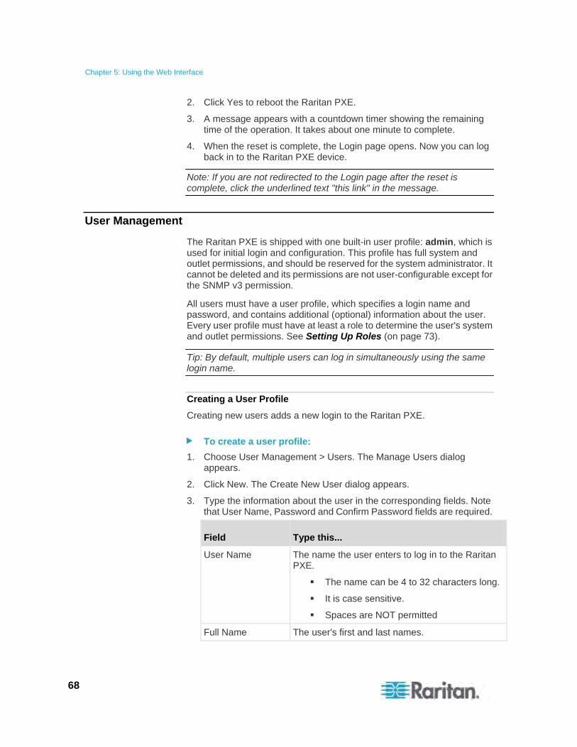
Chapter 5: Using the Web Interface
68
2. Click Yes to reboot the Raritan PXE.
3. A message appears with a countdown timer showing the remaining time of the operation. It takes about one minute to complete.
4. When the reset is complete, the Login page opens. Now you can log back in to the Raritan PXE device.
Note: If you are not redirected to the Login page after the reset is complete, click the underlined text "this link" in the message.
User Management
The Raritan PXE is shipped with one built-in user profile: admin, which is used for initial login and configuration. This profile has full system and outlet permissions, and should be reserved for the system administrator. It cannot be deleted and its permissions are not user-configurable except for the SNMP v3 permission.
All users must have a user profile, which specifies a login name and password, and contains additional (optional) information about the user. Every user profile must have at least a role to determine the user's system and outlet permissions. See Setting Up Roles (on page 73).
Tip: By default, multiple users can log in simultaneously using the same login name.
Creating a User Profile
Creating new users adds a new login to the Raritan PXE.
To create a user profile:
1. Choose User Management > Users. The Manage Users dialog appears.
2. Click New. The Create New User dialog appears.
3. Type the information about the user in the corresponding fields. Note that User Name, Password and Confirm Password fields are required.
Field Type this...
User Name The name the user enters to log in to the Raritan PXE.
The name can be 4 to 32 characters long.
It is case sensitive.
Spaces are NOT permitted
Full Name The user's first and last names.
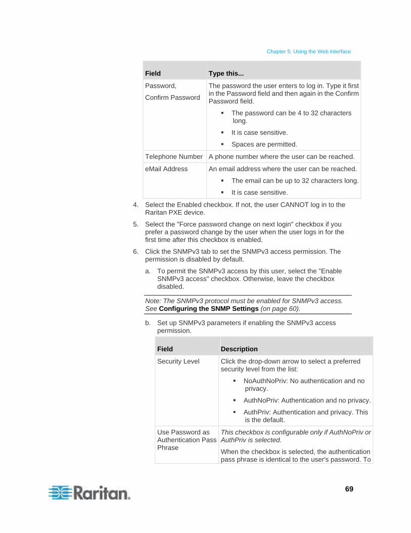
Chapter 5: Using the Web Interface
69
Field Type this...
Password,
Confirm Password
The password the user enters to log in. Type it first in the Password field and then again in the Confirm Password field.
The password can be 4 to 32 characters long.
It is case sensitive.
Spaces are permitted.
Telephone Number A phone number where the user can be reached.
eMail Address An email address where the user can be reached.
The email can be up to 32 characters long.
It is case sensitive.
4. Select the Enabled checkbox. If not, the user CANNOT log in to the Raritan PXE device.
5. Select the "Force password change on next login" checkbox if you prefer a password change by the user when the user logs in for the first time after this checkbox is enabled.
6. Click the SNMPv3 tab to set the SNMPv3 access permission. The permission is disabled by default.
a. To permit the SNMPv3 access by this user, select the "Enable SNMPv3 access" checkbox. Otherwise, leave the checkbox disabled.
Note: The SNMPv3 protocol must be enabled for SNMPv3 access. See Configuring the SNMP Settings (on page 60).
b. Set up SNMPv3 parameters if enabling the SNMPv3 access permission.
Field Description
Security Level Click the drop-down arrow to select a preferred security level from the list:
NoAuthNoPriv: No authentication and no privacy.
AuthNoPriv: Authentication and no privacy.
AuthPriv: Authentication and privacy. This is the default.
Use Password as Authentication Pass Phrase
This checkbox is configurable only if AuthNoPriv or AuthPriv is selected.
When the checkbox is selected, the authentication pass phrase is identical to the user's password. To
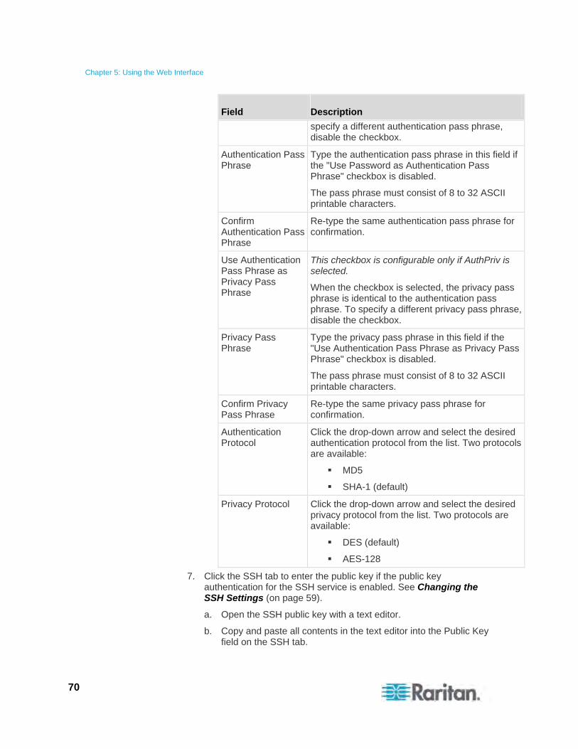
Chapter 5: Using the Web Interface
70
Field Description
specify a different authentication pass phrase, disable the checkbox.
Authentication Pass Phrase
Type the authentication pass phrase in this field if the "Use Password as Authentication Pass Phrase" checkbox is disabled.
The pass phrase must consist of 8 to 32 ASCII printable characters.
Confirm Authentication Pass Phrase
Re-type the same authentication pass phrase for confirmation.
Use Authentication Pass Phrase as Privacy Pass Phrase
This checkbox is configurable only if AuthPriv is selected.
When the checkbox is selected, the privacy pass phrase is identical to the authentication pass phrase. To specify a different privacy pass phrase, disable the checkbox.
Privacy Pass Phrase
Type the privacy pass phrase in this field if the "Use Authentication Pass Phrase as Privacy Pass Phrase" checkbox is disabled.
The pass phrase must consist of 8 to 32 ASCII printable characters.
Confirm Privacy Pass Phrase
Re-type the same privacy pass phrase for confirmation.
Authentication Protocol
Click the drop-down arrow and select the desired authentication protocol from the list. Two protocols are available:
MD5
SHA-1 (default)
Privacy Protocol Click the drop-down arrow and select the desired privacy protocol from the list. Two protocols are available:
DES (default)
AES-128
7. Click the SSH tab to enter the public key if the public key authentication for the SSH service is enabled. See Changing the SSH Settings (on page 59).
a. Open the SSH public key with a text editor.
b. Copy and paste all contents in the text editor into the Public Key field on the SSH tab.
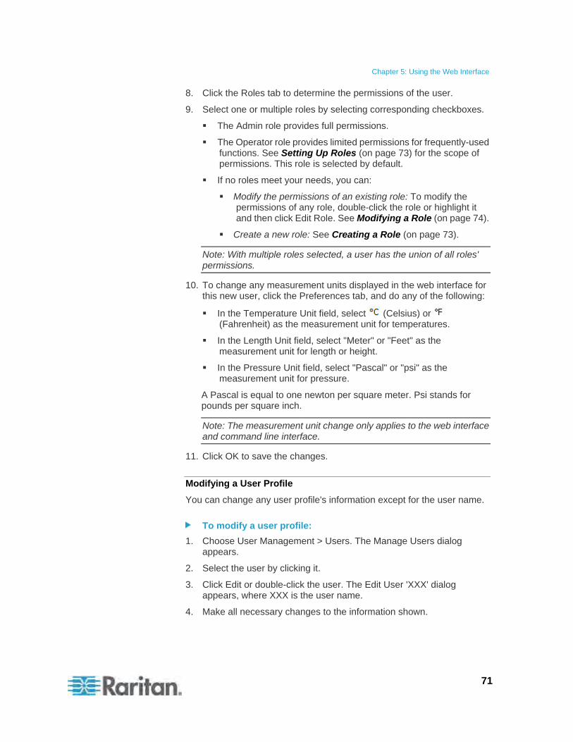
Chapter 5: Using the Web Interface
71
8. Click the Roles tab to determine the permissions of the user.
9. Select one or multiple roles by selecting corresponding checkboxes.
The Admin role provides full permissions.
The Operator role provides limited permissions for frequently-used functions. See Setting Up Roles (on page 73) for the scope of permissions. This role is selected by default.
If no roles meet your needs, you can:
Modify the permissions of an existing role: To modify the permissions of any role, double-click the role or highlight it and then click Edit Role. See Modifying a Role (on page 74).
Create a new role: See Creating a Role (on page 73).
Note: With multiple roles selected, a user has the union of all roles' permissions.
10. To change any measurement units displayed in the web interface for this new user, click the Preferences tab, and do any of the following:
In the Temperature Unit field, select (Celsius) or (Fahrenheit) as the measurement unit for temperatures.
In the Length Unit field, select "Meter" or "Feet" as the measurement unit for length or height.
In the Pressure Unit field, select "Pascal" or "psi" as the measurement unit for pressure.
A Pascal is equal to one newton per square meter. Psi stands for pounds per square inch.
Note: The measurement unit change only applies to the web interface and command line interface.
11. Click OK to save the changes.
Modifying a User Profile
You can change any user profile's information except for the user name.
To modify a user profile:
1. Choose User Management > Users. The Manage Users dialog appears.
2. Select the user by clicking it.
3. Click Edit or double-click the user. The Edit User 'XXX' dialog appears, where XXX is the user name.
4. Make all necessary changes to the information shown.
Chapter 5: Using the Web Interface
72
To change the password, type a new password in the Password and Confirm Password fields. If the password field is left blank, the password is not changed.
5. To change the SNMPv3 access permissions, click the SNMPv3 tab and make necessary changes. For details, see Step 6 of Creating a User Profile (on page 68).
6. To change the permissions, click the Roles tab and do one of these:
Select or deselect any role's checkbox.
To modify the permissions of any role, double-click the role or highlight it and then click Edit Role. See Modifying a Role (on page 74).
7. To change the measurement unit for temperature, length or pressure, click the Preferences tab, and select a different option from the drop-down list.
Note: The measurement unit change only applies to the web interface and command line interface.
8. Click OK to save the changes.
Deleting a User Profile
Delete outdated or redundant user profiles when necessary.
To delete user profiles:
1. Choose User Management > Users. The Manage Users dialog appears.
2. Select the user you want to delete by clicking it. To make multiple selections, press Ctrl+click or Shift+click to highlight multiple ones.
3. Click Delete.
4. A message appears, prompting you to confirm the operation. Click Yes to confirm the deletion.
Changing the User List View
You may change the number of displayed columns or re-sort the list for better viewing the data. See Changing the View of a List (on page 48).
Chapter 5: Using the Web Interface
73
Setting Up Roles
A role defines the operations and functions a user is permitted to perform or access. Every user must be assigned at least a role.
The Raritan PXE is shipped with two built-in roles: Admin and Operator.
The Admin role provides full permissions. You can neither modify nor delete this role.
The Operator role provides limited permissions for frequently-used functions. You can modify or delete this role. By default, the Operator role contains these permissions:
- View Event Settings
- View Local Event Log
- Change Event Settings
- Change Pdu, Inlet, Outlet & Overcurrent Protector Configuration
- Change Own Password
The Operator role is assigned to a newly created user profile by default. See Creating a User Profile (on page 68).
Creating a Role
Create a new role when you need a new combination of permissions.
To create a role:
1. Choose User Management > Roles. The Manage Roles dialog appears.
Tip: You can also access the Manage Roles dialog by clicking the Manage Roles button in the Edit User 'XXX' dialog.
2. Click New. The Create New Role dialog appears.
3. Type the role's name in the Role Name field.
4. Type a description for the role in the Description field.
5. Click the Privileges tab to assign one or multiple permissions.
a. Click Add. The "Add Privileges to new Role" dialog appears.
b. Select the permission you want from the Privileges list.
c. If the permission you selected contains any argument setting, the Arguments list is shown to the right. Then select one or multiple arguments.
d. Click Add to add the selected permission (and arguments if any).
e. Repeat Steps a to d until you add all necessary permissions.
Chapter 5: Using the Web Interface
74
6. Click OK to save the changes.
Now you can assign the new role to any users. See Creating a User Profile (on page 68) or Modifying a User Profile (on page 71).
Modifying a Role
You can change an existing role's settings except for the name.
To modify a role:
1. Choose User Management > Roles. The Manage Roles dialog appears.
Tip: You can also access the Manage Roles dialog by clicking the Manage Roles button in the Edit User 'XXX' dialog.
2. Select the role you want to modify by clicking it.
3. Click Edit or double-click the role. The Edit Role 'XXX' dialog appears, where XXX is the role name.
Tip: You can also access the Edit Role 'XXX' dialog by clicking the Edit Role button in the Edit User 'XXX' dialog.
4. Modify the text shown in the Description field if necessary.
5. To change the permissions, click the Privileges tab.
Note: You cannot change the Admin role's permissions.
6. To delete any permissions, do this:
a. Select the permission you want to remove by clicking it. To make multiple selections, press Ctrl+click or Shift+click to highlight multiple ones.
b. Click Delete.
7. To add any permissions, do this:
a. Click Add. The Add Privileges to Role 'XXX' dialog appears, where XXX is the role name.
b. Select the permission you want from the Privileges list.
c. If the permission you selected contains any argument setting, the Arguments list is shown to the right. Then select one or multiple arguments.
d. Click Add to add the selected permission (and arguments if any).
e. Repeat Steps a to d until you add all necessary permissions.
8. To change a specific permission's arguments, do this:
a. Select the permission by clicking it.
Chapter 5: Using the Web Interface
75
b. Click Edit. The "Edit arguments of privilege 'XXX'" dialog appears, where XXX is the privilege name.
Note: If the permission you selected does not contain any arguments, the Edit button is disabled.
c. Select the argument you want. You can make multiple selections.
d. Click OK.
9. Click OK to save the changes.
Deleting a Role
You can delete any role other than the Admin role.
To delete a role:
1. Choose User Management > Roles. The Manage Roles dialog appears.
Tip: You can also access the Manage Roles dialog by clicking the Manage Roles button in the Edit User 'XXX' dialog.
2. Select the role you want to delete by clicking it. To make multiple selections, press Ctrl+click or Shift+click to highlight multiple ones.
3. Click Delete.
4. A message appears, prompting you to confirm the operation. Click Yes to confirm the deletion.
Changing the Role List View
You may change the number of displayed columns or re-sort the list for better viewing the data. See Changing the View of a List (on page 48).
Access Security Control
The Raritan PXE provides tools to control access. You can require HTTPS encryption, enable the internal firewall and create firewall rules, and create login limitations.
Tip: You can also create and install the certificate or set up external authentication servers to control any access. See Setting Up an SSL Certificate (on page 87) and Setting Up LDAP Authentication (on page 92).
Chapter 5: Using the Web Interface
76
Forcing HTTPS Encryption
HTTPS uses Secure Sockets Layer (SSL) technology to encrypt all traffic to and from the Raritan PXE device so it is a more secure protocol than HTTP.
You can force users to access the Raritan PXE web interface through the HTTPS protocol only. By default, this protocol is enabled.
To force HTTPS access to the web interface:
1. Choose Device Settings > Security > Force HTTPS for Web Access.
2. A message appears, prompting you to confirm the operation. Click Yes to enforce the HTTPS service.
3. Choose Device Settings > Security to verify the "Force HTTPS for Web Access" checkbox is selected as shown in this diagram.
If the checkbox is not selected, repeat these steps.
After enabling the HTTPS protocol, all access attempts using HTTP are redirected to HTTPS automatically.
Configuring the Firewall
The Raritan PXE has a firewall that you can configure to prevent specific IP addresses and ranges of IP addresses from accessing the Raritan PXE device. By default the firewall is disabled.
To configure the firewall:
1. Enable the firewall. See Enabling the Firewall (on page 77).
2. Set the default policy. See Changing the Default Policy (on page 77).
3. Create firewall rules specifying which addresses to accept and which ones to discard. See Creating Firewall Rules (on page 78).
Changes made to firewall rules take effect immediately. Any unauthorized IP activities cease instantly.
Note: The purpose of disabling the firewall by default is to prevent users from accidentally locking themselves out of the device.
Chapter 5: Using the Web Interface
77
Enabling the Firewall
The firewall rules, if any, take effect only after the firewall is enabled.
To enable the Raritan PXE firewall:
1. Choose Device Settings > Security > IP Access Control. The Configure IP Access Control Settings dialog appears.
2. Select the Enable IP Access Control checkbox. This enables the firewall.
3. Click OK to save the changes.
Changing the Default Policy
After enabling the firewall, the default policy is to accept traffic from all IP addresses. This means only IP addresses discarded by a specific rule will NOT be permitted to access the Raritan PXE.
You can change the default policy to Drop or Reject, in which case traffic from all IP addresses is discarded except the IP addresses accepted by a specific rule.
To change the default policy:
1. Choose Device Settings > Security > IP Access Control. The Configure IP Access Control Settings dialog appears.
2. Ensure the Enable IP Access Control checkbox is selected.
3. The default policy is shown in the Default Policy field. To change it, select a different policy from the drop-down list.
Accept: Accepts traffic from all IP addresses.
Drop: Discards traffic from all IP addresses, without sending any failure notification to the source host.
Reject: Discards traffic from all IP addresses, and an ICMP message is sent to the source host for failure notification.
4. Click OK to save the changes. The new default policy is applied.
Chapter 5: Using the Web Interface
78
Creating Firewall Rules
Firewall rules determine whether to accept or discard traffic intended for the Raritan PXE, based on the IP address of the host sending the traffic. When creating firewall rules, keep these principles in mind:
Rule order is important.
When traffic reaches the Raritan PXE device, the rules are executed in numerical order. Only the first rule that matches the IP address determines whether the traffic is accepted or discarded. Any subsequent rules matching the IP address are ignored by the Raritan PXE.
Subnet mask may be required.
When typing the IP address, you may or may not need to specify BOTH the address and a subnet mask. The default subnet mask is /32 (that is, 255.255.255.255). You must specify a subnet mask only when it is not the same as the default. For example, to specify a single address in a Class C network, use this format:
x.x.x.x/24
where /24 = a subnet mask of 255.255.255.0.
To specify an entire subnet or range of addresses, change the subnet mask accordingly.
Note: Valid IP addresses range from 0.0.0.0 through 255.255.255.255. Make sure the IP addresses entered are within the scope.
To create firewall rules:
1. Choose Device Settings > Security > IP Access Control. The Configure IP Access Control Settings dialog appears.
2. Ensure the Enable IP Access Control checkbox is selected.
3. Create specific rules. See the table for different operations.
Action Procedure
Add a rule to the end of the rules list
Click Append. The "Append new Rule" dialog appears.
Type an IP address and subnet mask in the IP/Mask field.
Select Accept, Drop or Reject from the drop-down list in the Policy field.
Accept: Accepts traffic from the specified IP address(es).
Drop: Discards traffic from the specified IP address(es), without sending any failure notification to the source host.
Reject: Discards traffic from the specified IP address(es), and an ICMP message is sent to the source host for failure notification.
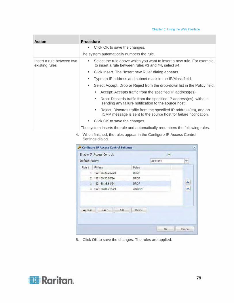
Chapter 5: Using the Web Interface
79
Action Procedure
Click OK to save the changes.
The system automatically numbers the rule.
Insert a rule between two existing rules
Select the rule above which you want to insert a new rule. For example, to insert a rule between rules #3 and #4, select #4.
Click Insert. The "Insert new Rule" dialog appears.
Type an IP address and subnet mask in the IP/Mask field.
Select Accept, Drop or Reject from the drop-down list in the Policy field.
Accept: Accepts traffic from the specified IP address(es).
Drop: Discards traffic from the specified IP address(es), without sending any failure notification to the source host.
Reject: Discards traffic from the specified IP address(es), and an ICMP message is sent to the source host for failure notification.
Click OK to save the changes.
The system inserts the rule and automatically renumbers the following rules.
4. When finished, the rules appear in the Configure IP Access Control Settings dialog.
5. Click OK to save the changes. The rules are applied.
Chapter 5: Using the Web Interface
80
Editing Firewall Rules
When an existing firewall rule requires updates of IP address range and/or policy, modify them accordingly.
To modify a firewall rule:
1. Choose Device Settings > Security > IP Access Control. The Configure IP Access Control Settings dialog appears.
2. Ensure the Enable IP Access Control checkbox is selected.
3. Select the rule to be modified in the rules list.
4. Click Edit or double-click the rule. The Edit Rule dialog appears.
5. Make changes to the information shown.
6. Click OK to save the changes.
7. Click OK to quit the Configure IP Access Control Settings dialog, or the changes are lost.
Sorting Firewall Rules
The rule order determines which one of the rules matching the same IP address is performed.
To sort the firewall rules:
1. Choose Device Settings > Security > IP Access Control. The Configure IP Access Control Settings dialog appears.
2. Ensure the Enable IP Access Control checkbox is selected.
3. Select a specific rule by clicking it.
4. Click or to move the selected rule up or down until it reaches the desired location.
5. Click OK to save the changes.
Deleting Firewall Rules
When any firewall rules become obsolete or unnecessary, remove them from the rules list.
To delete a firewall rule:
1. Choose Device Settings > Security > IP Access Control. The Configure IP Access Control Settings dialog appears.
2. Ensure the Enable IP Access Control checkbox is selected.
3. Select the rule that you want to delete. To make multiple selections, press Ctrl+click or Shift+click to highlight multiple ones.
Chapter 5: Using the Web Interface
81
4. Click Delete.
5. A message appears, prompting you to confirm the operation. Click Yes to remove the selected rule(s) from the rules list.
6. Click OK to save the changes.
Setting Up User Login Controls
You can set up login controls to make it more difficult for hackers to access the Raritan PXE and the devices connected to it. You can arrange to lock persons out after a specified number of failed logins, limit the number of persons who log in using the same user name at the same time, and force users to create strong passwords.
Enabling User Blocking
User blocking determines how many times a user can attempt to log in to the Raritan PXE and fail authentication before the user's login is blocked.
Note that this function applies only to local authentication instead of authentication through external AA servers.
Note: If any user blocking event occurs, you can unblock that user manually by using the "unblock" CLI command via a serial connection. See Unblocking a User (on page 250).
To enable user blocking:
1. Choose Device Settings > Security > Login Settings. The Login Settings dialog appears.
2. Locate the User Blocking section.
3. To enable the user blocking feature, select the "Block user on login failure" checkbox.
4. Type a number in the "Maximum number of failed logins" field. This is the maximum number of failed logins the user is permitted before the user's login is blocked from accessing the Raritan PXE device.
5. To determine how long the login is blocked, select the desired length of time from the drop-down list in the "Block timeout" field. The following describes available options.
Infinite: This option sets no time limit on blocking the login.
X min: This type of option sets the time limit to X minutes, where X is a number.
X h: This type of option sets the time limit to X hours, where X is a number.
1 d: This option sets the time limit to 1 day.
Chapter 5: Using the Web Interface
82
Tip: If the desired time option is not listed, you can manually type the desired time in this field. For example, you can type "4 min" to set the time to 4 minutes.
6. Click OK to save the changes.
Enabling Login Limitations
Login limitations determine whether more than one person can use the same login name at the same time, and how long users are permitted to stay idle before being forced to log out.
To enable login limitations:
1. Choose Device Settings > Security > Login Settings. The Login Settings dialog appears.
2. Locate the Login Limitations section.
3. To prevent more than one person from using the same login at the same time, select the "Prevent concurrent login with same username" checkbox.
4. To adjust how long users can remain idle before they are forcibly logged out by the Raritan PXE, select a time option in the Idle Timeout Period field. The default is 10 minutes.
X min: This type of option sets the time limit to X minutes, where X is a number.
X h: This type of option sets the time limit to X hours, where X is a number.
1 d: This option sets the time limit to 1 day.
Tip: If the desired time option is not listed, you can manually type the desired time in this field. For example, you can type "4 min" to set the time to 4 minutes.
5. Click OK to save the changes.
Tip: Keep the idle timeout to 20 minutes or less if possible. This reduces the number of idle sessions connected, and the number of simultaneous commands sent to the Raritan PXE.
Chapter 5: Using the Web Interface
83
Enabling Strong Passwords
Use of strong passwords makes it more difficult for intruders to crack user passwords and access the Raritan PXE device. By default, strong passwords should be at least eight characters long and contain upper- and lower-case letters, numbers, and special characters, such as @ or &.
To force users to create strong passwords:
1. Choose Device Settings > Security > Password Policy. The Password Policy dialog appears.
2. Select the Strong Passwords checkbox to activate the strong password feature. The following are the default settings:
Minimum length = 8 characters
Maximum length = 32 characters
At least one lowercase character = Required
At least one uppercase character = Required
At least one numeric character = Required
At least one special character = Required
Number of restricted passwords in history = 5
Note: The maximum password length accepted by the Raritan PXE is 32 characters.
3. Make necessary changes to the default settings.
4. Click OK to save the changes.
Enabling Password Aging
Password Aging determines whether users are required to change passwords at regular intervals. The default interval is 60 days.
To force users to change passwords regularly:
1. Choose Device Settings > Security > Password Policy. The Password Policy dialog appears.
2. Select the Password Aging checkbox to enable the password aging feature.
3. To determine how often users are requested to change their passwords, select a number of days in the Password Aging Interval field. Users are required to change their password every time that number of days has passed.
Chapter 5: Using the Web Interface
84
Tip: If the desired time option is not listed, you can manually type the desired time in this field. For example, you can type "9 d" to set the password aging time to 9 days.
4. Click OK to save the changes.
Setting Up Role-Based Access Control Rules
Role-based access control rules are similar to firewall rules, except they are applied to members sharing a specific role. This enables you to grant system permissions to a specific role, based on their IP addresses.
To set up role-based access control rules:
1. Enable the feature. See Enabling the Feature (on page 84).
2. Set the default policy. See Changing the Default Policy (on page 84).
3. Create rules specifying which addresses to accept and which ones to discard when the addresses are associated with a specific role. See Creating Role-Based Access Control Rules (on page 85).
Changes made do not affect users currently logged in until the next login.
Enabling the Feature
You must enable this access control feature before any relevant rule can take effect.
To enable role-based access control rules:
1. Choose Device Settings > Security > Role Based Access Control. The Configure Role Based Access Control Settings dialog appears.
2. Select the Enable Role Based Access Control checkbox. This enables the feature.
3. Click OK to save the changes.
Changing the Default Policy
The default policy is to accept all traffic from all IP addresses regardless of the role applied to the user.
To change the default policy:
1. Choose Device Settings > Security > Role Based Access Control. The Configure Role Based Access Control Settings dialog appears.
2. Make sure the Enable Role Based Access Control checkbox is selected.
3. Select the action you want from the Default Policy drop-down list.

Chapter 5: Using the Web Interface
85
Allow: Accepts traffic from all IP addresses regardless of the user's role.
Deny: Drops traffic from all IP addresses regardless of the user's role.
4. Click OK to save the changes.
Creating Role-Based Access Control Rules
Role-based access control rules accept or drop traffic, based on the user's role and IP address. Like firewall rules, the order of rules is important, since the rules are executed in numerical order.
To create role-based access control rules:
1. Choose Device Settings > Security > Role Based Access Control. The Configure Role Based Access Control Settings dialog appears.
2. Make sure the Enable Role Based Access Control checkbox is selected.
3. Create specific rules:
Action Do this...
Add a rule to the end of the rules list
Click Append. The "Append new Rule" dialog appears.
Type a starting IP address in the Starting IP Address field.
Type an ending IP address in the Ending IP Address field.
Select a role from the drop-down list in the Role field. This rule applies to members of this role only.
Select Allow or Deny from the drop-down list in the Policy field.
Allow: Accepts traffic from the specified IP address range when the user is a member of the specified role
Deny: Drops traffic from the specified IP address range when the user is a member of the specified role
Click OK to save the changes.
The system automatically numbers the rule.
Insert a rule between two existing rules
Select the rule above which you want to insert a new rule. For example, to insert a rule between rules #3 and #4, select #4.
Click Insert. The "Insert new Rule" dialog appears.
Type a starting IP address in the Starting IP Address
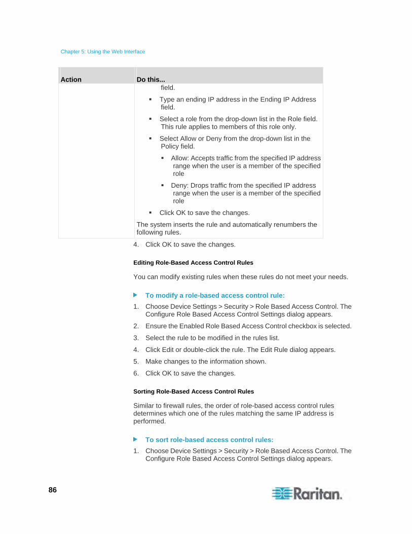
Chapter 5: Using the Web Interface
86
Action Do this... field.
Type an ending IP address in the Ending IP Address field.
Select a role from the drop-down list in the Role field. This rule applies to members of this role only.
Select Allow or Deny from the drop-down list in the Policy field.
Allow: Accepts traffic from the specified IP address range when the user is a member of the specified role
Deny: Drops traffic from the specified IP address range when the user is a member of the specified role
Click OK to save the changes.
The system inserts the rule and automatically renumbers the following rules.
4. Click OK to save the changes.
Editing Role-Based Access Control Rules
You can modify existing rules when these rules do not meet your needs.
To modify a role-based access control rule:
1. Choose Device Settings > Security > Role Based Access Control. The Configure Role Based Access Control Settings dialog appears.
2. Ensure the Enabled Role Based Access Control checkbox is selected.
3. Select the rule to be modified in the rules list.
4. Click Edit or double-click the rule. The Edit Rule dialog appears.
5. Make changes to the information shown.
6. Click OK to save the changes.
Sorting Role-Based Access Control Rules
Similar to firewall rules, the order of role-based access control rules determines which one of the rules matching the same IP address is performed.
To sort role-based access control rules:
1. Choose Device Settings > Security > Role Based Access Control. The Configure Role Based Access Control Settings dialog appears.
Chapter 5: Using the Web Interface
87
2. Ensure the Enabled Role Based Access Control checkbox is selected.
3. Select a specific rule by clicking it.
4. Click or to move the selected rule up or down until it reaches the desired location.
5. Click OK to save the changes.
Deleting Role-Based Access Control Rules
When any access control rule becomes unnecessary or obsolete, remove it.
To delete a role-based access control rule:
1. Choose Device Settings > Security > Role Based Access Control. The Configure Role Based Access Control Settings dialog appears.
2. Ensure the Enabled Role Based Access Control checkbox is selected.
3. Select the rule to be deleted in the rules list. To make multiple selections, press Ctrl+click or Shift+click to highlight multiple ones.
4. Click Delete.
5. A message appears, prompting you to confirm the operation. Click Yes to confirm the deletion.
6. Click OK to save the changes.
Setting Up an SSL Certificate
Having an X.509 digital certificate ensures that both parties in an SSL connection are who they say they are.
To obtain a certificate for the Raritan PXE, create a Certificate Signing Request (CSR) and submit it to a certificate authority (CA). After the CA processes the information in the CSR, it provides you with an SSL certificate, which you must install on the Raritan PXE device.
Note: See Forcing HTTPS Encryption (on page 76) for instructions on forcing users to employ SSL when connecting to the Raritan PXE.
A CSR is not required in either of the following scenarios:
You decide to generate a self-signed certificate on the Raritan PXE device.
Appropriate, valid certificate and key files have been available.

Chapter 5: Using the Web Interface
88
Certificate Signing Request
When appropriate certificate and key files for the Raritan PXE are NOT available, one of the alternatives is to create a CSR and private key on the Raritan PXE device, and send the CSR to a CA for signing the certificate.
Creating a Certificate Signing Request
Follow this procedure to create the CSR for your Raritan PXE device.
To create a CSR:
1. Choose Device Settings > Security > SSL Certificate. The Manage SSL Certificate dialog appears.
2. Click the New SSL Certificate tab.
3. Provide the information requested.
In the Subject section:
Field Type this information
Country (ISO Code) The country where your company is located. Use the standard ISO country code. For a list of ISO codes, visit the ISO website (http://www.iso.org/iso/country_codes/iso_3166_code_lists.htm).
State or Province The full name of the state or province where your company is located.
Locality The city where your company is located.
Organization The registered name of your company.
Organizational Unit The name of your department.
Common Name The fully qualified domain name (FQDN) of your Raritan PXE device.
Email Address An email address where you or another administrative user can be reached.
Note: All fields in the Subject section are mandatory, except for the Organization, Organizational Unit and Email Address fields. If you generate a CSR without values entered in the required fields, you cannot obtain third party certificates.
In the Key Creation Parameters section:
Field Do this
Key Length Select the key length (bits) from the drop-down list in this field. A larger key length enhances the security, but slows down the Raritan PXE device's response.
Self Sign For requesting a certificate signed by the CA, ensure this checkbox is NOT selected.
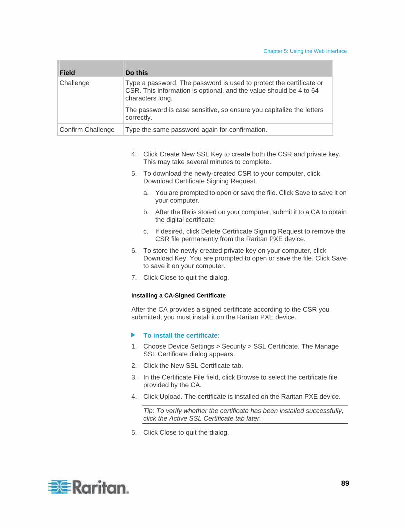
Chapter 5: Using the Web Interface
89
Field Do this
Challenge Type a password. The password is used to protect the certificate or CSR. This information is optional, and the value should be 4 to 64 characters long.
The password is case sensitive, so ensure you capitalize the letters correctly.
Confirm Challenge Type the same password again for confirmation.
4. Click Create New SSL Key to create both the CSR and private key. This may take several minutes to complete.
5. To download the newly-created CSR to your computer, click Download Certificate Signing Request.
a. You are prompted to open or save the file. Click Save to save it on your computer.
b. After the file is stored on your computer, submit it to a CA to obtain the digital certificate.
c. If desired, click Delete Certificate Signing Request to remove the CSR file permanently from the Raritan PXE device.
6. To store the newly-created private key on your computer, click Download Key. You are prompted to open or save the file. Click Save to save it on your computer.
7. Click Close to quit the dialog.
Installing a CA-Signed Certificate
After the CA provides a signed certificate according to the CSR you submitted, you must install it on the Raritan PXE device.
To install the certificate:
1. Choose Device Settings > Security > SSL Certificate. The Manage SSL Certificate dialog appears.
2. Click the New SSL Certificate tab.
3. In the Certificate File field, click Browse to select the certificate file provided by the CA.
4. Click Upload. The certificate is installed on the Raritan PXE device.
Tip: To verify whether the certificate has been installed successfully, click the Active SSL Certificate tab later.
5. Click Close to quit the dialog.
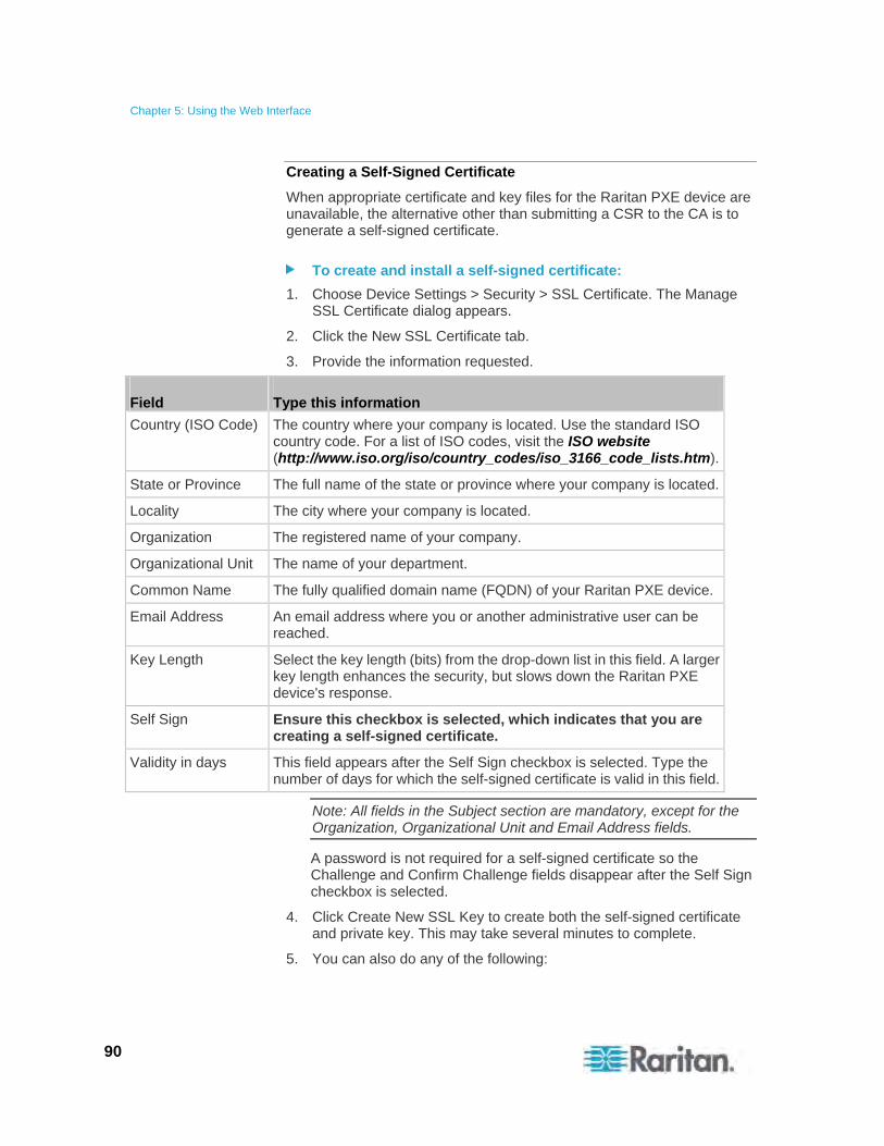
Chapter 5: Using the Web Interface
90
Creating a Self-Signed Certificate
When appropriate certificate and key files for the Raritan PXE device are unavailable, the alternative other than submitting a CSR to the CA is to generate a self-signed certificate.
To create and install a self-signed certificate:
1. Choose Device Settings > Security > SSL Certificate. The Manage SSL Certificate dialog appears.
2. Click the New SSL Certificate tab.
3. Provide the information requested.
Field Type this information
Country (ISO Code) The country where your company is located. Use the standard ISO country code. For a list of ISO codes, visit the ISO website (http://www.iso.org/iso/country_codes/iso_3166_code_lists.htm).
State or Province The full name of the state or province where your company is located.
Locality The city where your company is located.
Organization The registered name of your company.
Organizational Unit The name of your department.
Common Name The fully qualified domain name (FQDN) of your Raritan PXE device.
Email Address An email address where you or another administrative user can be reached.
Key Length Select the key length (bits) from the drop-down list in this field. A larger key length enhances the security, but slows down the Raritan PXE device's response.
Self Sign Ensure this checkbox is selected, which indicates that you are creating a self-signed certificate.
Validity in days This field appears after the Self Sign checkbox is selected. Type the number of days for which the self-signed certificate is valid in this field.
Note: All fields in the Subject section are mandatory, except for the Organization, Organizational Unit and Email Address fields.
A password is not required for a self-signed certificate so the Challenge and Confirm Challenge fields disappear after the Self Sign checkbox is selected.
4. Click Create New SSL Key to create both the self-signed certificate and private key. This may take several minutes to complete.
5. You can also do any of the following:
Chapter 5: Using the Web Interface
91
Click "Install Key and Certificate" to immediately install the self-signed certificate and private key. When any confirmation and security messages appear, click Yes to continue.
Tip: To verify whether the certificate has been installed successfully, click the Active SSL Certificate tab later.
To download the self-signed certificate or private key, click Download Certificate or Download Key. You are prompted to open or save the file. Click Save to save it on your computer.
To remove the self-signed certificate and private key permanently from the Raritan PXE device, click "Delete Key and Certificate".
6. If you installed the self-signed certificate in Step 5, after the installation completes, the Raritan PXE device resets and the login page re-opens.
Installing Existing Key and Certificate Files
If the SSL certificate and private key files are already available, you can install them directly without going through the process of creating a CSR or a self-signed certificate.
To install the existing key and certificate files:
1. Choose Device Settings > Security > SSL Certificate. The Manage SSL Certificate dialog appears.
2. Click the New SSL Certificate tab.
3. Select the "Upload Key and Certificate" checkbox. The Key File and Certificate File fields appear.
4. In the Key File field, click Browse to select the private key file.
5. In the Certificate File field, click Browse to select the certificate file.
6. Click Upload. The selected files are installed on the Raritan PXE device.
Tip: To verify whether the certificate has been installed successfully, click the Active SSL Certificate tab later.
7. Click Close to quit the dialog.
Chapter 5: Using the Web Interface
92
Downloading Key and Certificate Files
You can download the key and certificate files currently installed on the Raritan PXE device for backup or other operations. For example, you can install the files on a replacement Raritan PXE device, add the certificate to your browser and so on.
To download the certificate and key files from a Raritan PXE device:
1. Choose Device Settings > Security > SSL Certificate. The Manage SSL Certificate dialog appears.
2. The Active SSL Certificate tab should open. If not, click it.
3. Click Download Key to download the private key file installed on the Raritan PXE device. You are prompted to open or save the file. Click Save to save it on your computer.
4. Click Download Certificate to download the certificate file installed on the Raritan PXE device. You are prompted to open or save the file. Click Save to save it on your computer.
5. Click Close to quit the dialog.
Setting Up LDAP Authentication
For security purposes, users attempting to log in to the Raritan PXE must be authenticated. The Raritan PXE supports the access using one of the following authentication mechanisms:
Local database of user profiles on the Raritan PXE device
Lightweight Directory Access Protocol (LDAP)
By default, the Raritan PXE is configured for local authentication. If you stay with this method, you do not need to do anything other than create user profiles for each authorized user. If you prefer to use an external LDAP server, you must:
Provide the Raritan PXE with information about the LDAP server.
Create user profiles for users who are authenticated externally because a user profile on the Raritan PXE device determines the role(s) applied to the user, and determines the permissions for the user accordingly.
When configured for LDAP authentication, all Raritan PXE users must have an account on the LDAP server. Local-authentication-only users will have no access to the Raritan PXE except for the admin, who always can access the Raritan PXE.
Chapter 5: Using the Web Interface
93
Gathering the LDAP Information
It requires knowledge of your LDAP server and directory settings to configure the Raritan PXE for LDAP authentication. If you are not familiar with the settings, consult your LDAP administrator for help.
To configure LDAP authentication, you need to check:
The IP address or hostname of the LDAP server
Whether the Secure LDAP protocol (LDAP over SSL) is being used
If Secure LDAP is in use, consult your LDAP administrator for the CA certificate file.
The network port used by the LDAP server
The type of the LDAP server, usually one of the following options:
OpenLDAP
If using an OpenLDAP server, consult the LDAP administrator for the Bind Distinguished Name (DN) and password.
Microsoft Active Directory® (AD)
If using a Microsoft Active Directory server, consult your AD administrator for the name of the Active Directory Domain.
Bind Distinguished Name (DN) and password (if anonymous bind is NOT used)
The Base DN of the server (used for searching for users)
The login name attribute (or AuthorizationString)
The user entry object class
The user search subfilter (or BaseSearch)
Adding the LDAP Server Settings
To activate and use external LDAP/LDAPS server authentication, enable LDAP authentication and enter the information you have gathered for any LDAP/LDAPS server.
Note: An LDAPS server refers to an SSL-secured LDAP server.
To add the LDAP/LDAPS server settings:
1. Choose Device Settings > Security > Authentication. The Authentication Settings dialog appears.
2. Select the LDAP radio button to activate remote LDAP/LDAPS server authentication.
3. Click New to add an LDAP/LDAPS server for authentication. The "Create new LDAP Server Configuration" dialog appears.
Chapter 5: Using the Web Interface
94
4. IP Address / Hostname - Type the IP address or hostname of your LDAP/LDAPS authentication server.
Important: Without the SSL encryption enabled, you can type either the domain name or IP address in this field, but you must type the fully qualified domain name if the SSL encryption is enabled.
5. Type of external LDAP/LDAPS server. Choose from among the options available:
OpenLDAP
Microsoft Active Directory. Active Directory is an implementation of LDAP/LDAPS directory services by Microsoft for use in Windows environments.
6. LDAP over SSL - Select this checkbox if you would like to use SSL. Secure Sockets Layer (SSL) is a cryptographic protocol that allows the Raritan PXE to communicate securely with the LDAP/LDAPS server. A certificate file is required when enabling the encryption.
7. Port - The default Port is 389. Either use the standard LDAP TCP port or specify another port.
8. SSL Port - The default is 636. Either use the default port or specify another port. This field is enabled when the "LDAP over SSL" checkbox is selected.
9. Use only trusted LDAP Server Certificates - Select this checkbox if you would like to use a trusted LDAP server certificate file, that is, a certificate file signed by the CA. When NOT selected, you can use all LDAP/LDAPS server certificates, including a self-signed certificate file.
10. Server Certificate - Consult your authentication server administrator to get the CA certificate file for the LDAP/LDAPS server. Use the Browse button to navigate to the certificate file. This field is required when the "LDAP over SSL" checkbox is selected.
11. Anonymous Bind - For "OpenLDAP," use this checkbox to enable or disable anonymous bind.
To use anonymous bind, select this checkbox.
When a Bind DN and password are required to bind to the external LDAP/LDAPS server, deselect this checkbox.
12. Use Bind Credentials - For "Microsoft Active Directory," use this checkbox to enable or disable anonymous bind.
To use anonymous bind, deselect this checkbox. By default it is deselected.
When a Bind DN and password are required to bind to the external LDAP/LDAPS server, select this checkbox.
Chapter 5: Using the Web Interface
95
13. Bind DN - Specify the DN of the user who is permitted to search the LDAP directory in the defined search base. This information is required only when the Use Bind Credentials checkbox is selected.
14. Bind Password and Confirm Bind Password - Enter the Bind password in the Bind Password field first and then the Confirm Bind Password field. This information is required only when the Use Bind Credentials checkbox is selected.
15. Base DN for Search - Enter the name you want to bind against the LDAP/LDAPS (up to 31 characters), and where in the database to begin searching for the specified Base DN. An example Base Search value might be: cn=Users,dc=raritan,dc=com. Consult your authentication server administrator for the appropriate values to enter into these fields.
16. Type the following information in the corresponding fields. LDAP needs this information to verify user names and passwords.
Login name attribute (also called AuthorizationString)
User entry object class
User search subfilter (also called BaseSearch)
Note: The Raritan PXE will preoccupy the login name attribute and user entry object class with default values, which should not be changed unless required.
17. Active Directory Domain - Type the name of the Active Directory Domain. For example, testradius.com. Consult with your Active Directory Administrator for a specific domain name.
18. To verify if the LDAP/LDAPS configuration is done correctly, you may click Test Connection to check whether the Raritan PXE can connect to the LDAP/LDAPS server successfully.
Tip: You can also do this by using the Test Connection button in the Authentication Settings dialog.
19. Click OK to save the changes. The new LDAP server is listed in the Authentication Settings dialog.
20. To add additional LDAP/LDAPS servers, repeat Steps 3 to 19.
21. Click OK to save the changes. The LDAP authentication is now in place.
Note: If the Raritan PXE clock and the LDAP server clock are out of sync, the certificates are considered expired and users are unable to authenticate using LDAP. To ensure proper synchronization, administrators should configure the Raritan PXE and the LDAP server to use the same NTP server.
Chapter 5: Using the Web Interface
96
More Information about AD Configuration
For more information about the LDAP configuration using Microsoft Active Directory, see LDAP Configuration Illustration (on page 264).
Sorting the LDAP Access Order
The order of the LDAP list determines the access priority of remote LDAP/LDAPS servers. The Raritan PXE first tries to access the top LDAP/LDAPS server in the list for authentication, then the next one if the access to the first one fails, and so on until the Raritan PXE device successfully connects to one of the listed LDAP/LDAPS servers.
Note: After successfully connecting to one LDAP/LDAPS server, the Raritan PXE STOPS trying to access the remaining LDAP/LDAPS servers in the list regardless of the user authentication result.
To re-sort the LDAP server access list:
1. Choose Device Settings > Security > Authentication. The Authentication Settings dialog appears.
2. Select the LDAP/LDAPS server whose priority you want to change.
3. Click "Move up" or "Move down" until the selected server reaches the desired position in the list.
4. Click OK to save the changes.
Testing the LDAP Server Connection
You can test the connection to any LDAP/LDAPS server to verify the server accessibility or the validity of the authentication settings.
To test the connection to an LDAP/LDAPS server:
1. Choose Device Settings > Security > Authentication. The Authentication Settings dialog appears.
2. Select the LDAP/LDAPS server that you want to test.
3. Click Test Connection to start the connection test.
Chapter 5: Using the Web Interface
97
Editing the LDAP Server Settings
If the configuration on any LDAP/LDAPS server has been changed, such as the port number, bind DN and password, you must modify the LDAP/LDAPS settings on the Raritan PXE device accordingly, or the authentication fails.
To modify the LDAP authentication configuration:
1. Choose Device Settings > Security > Authentication. The Authentication Settings dialog appears.
2. Select the LDAP/LDAPS server that you want to edit.
3. Click Edit. The Edit LDAP Server Configuration dialog appears.
4. Make necessary changes to the information shown.
5. Click OK to save the changes.
Deleting the LDAP Server Settings
You can delete the authentication settings of a specific LDAP/LDAPS server when the server is not available or used for remote authentication.
To remove one or multiple LDAP/LDAPS servers:
1. Choose Device Settings > Security > Authentication. The Authentication Settings dialog appears.
2. Select the LDAP/LDAPS server that you want to remove. To make multiple selections, press Ctrl+click or Shift+click to highlight multiple ones.
3. Click Delete.
4. A message appears, prompting you to confirm the operation. Click Yes to confirm the deletion.
5. Click OK to save the changes.
Disabling the LDAP Authentication
When the remote authentication service is disabled, the Raritan PXE authenticates users against the local database stored on the Raritan PXE device.
To disable the LDAP authentication service:
1. Choose Device Settings > Security > Authentication. The Authentication Settings dialog appears.
2. Select the Local Authentication radio button.
3. Click OK to save the changes.
Chapter 5: Using the Web Interface
98
Enabling LDAP and Local Authentication Services
To make authentication function properly all the time -- even when external authentication is not available, you can enable both the local and remote authentication services.
When both authentication services are enabled, the Raritan PXE follows these rules for authentication:
When any of the LDAP/LDAPS servers in the access list is accessible, the Raritan PXE authenticates against the connected LDAP/LDAPS server only.
When the connection to every LDAP/LDAPS server fails, the Raritan PXE allows authentication against the local database.
To enable both authentication services:
1. Choose Device Settings > Security > Authentication. The Authentication Settings dialog appears.
2. Ensure the LDAP radio button has been selected.
3. Select the "Use Local Authentication if Remote Authentication service is not available" checkbox.
4. Click OK to save the changes.
Outlet Management
The Raritan PXE allows you to remotely customize the name of each outlet or remotely check which circuit breaker is associated with each outlet through the web interface.
Naming Outlets
You can give each outlet a unique name up to 32 characters long to identify the equipment connected to it. The customized name is followed by the label in parentheses.
Note: In this context, the label refers to the outlet number, such as 1, 2, 3 and so on.
To name an outlet:
1. If the PDU folder is not expanded, expand it to show all components and component groups. See Expanding the Tree (on page 42).
2. Click Outlets in the Dominion PX Explorer pane, and the Outlets page opens in the right pane.
3. Click the outlet you want in the right pane.
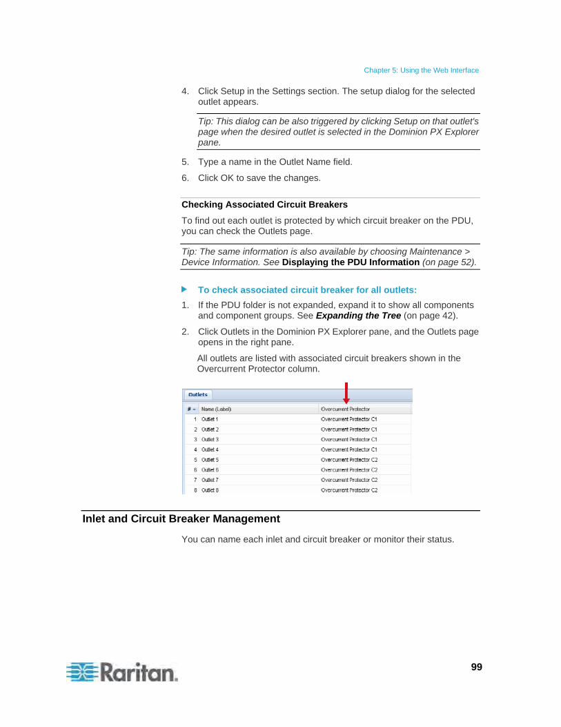
Chapter 5: Using the Web Interface
99
4. Click Setup in the Settings section. The setup dialog for the selected outlet appears.
Tip: This dialog can be also triggered by clicking Setup on that outlet's page when the desired outlet is selected in the Dominion PX Explorer pane.
5. Type a name in the Outlet Name field.
6. Click OK to save the changes.
Checking Associated Circuit Breakers
To find out each outlet is protected by which circuit breaker on the PDU, you can check the Outlets page.
Tip: The same information is also available by choosing Maintenance > Device Information. See Displaying the PDU Information (on page 52).
To check associated circuit breaker for all outlets:
1. If the PDU folder is not expanded, expand it to show all components and component groups. See Expanding the Tree (on page 42).
2. Click Outlets in the Dominion PX Explorer pane, and the Outlets page opens in the right pane.
All outlets are listed with associated circuit breakers shown in the Overcurrent Protector column.
Inlet and Circuit Breaker Management
You can name each inlet and circuit breaker or monitor their status.
Chapter 5: Using the Web Interface
100
Naming the Inlet
You can customize the inlet's name for your own purpose. The customized name is followed by the label in parentheses.
Note: In this context, the label refers to the inlet number, such as I1.
To name the inlet:
1. If the PDU folder is not expanded, expand it to show all components and component groups. See Expanding the Tree (on page 42).
2. Click Inlet I1 in the Dominion PX Explorer pane, and the Inlet I1 page opens in the right pane.
3. Click Setup. The Inlet I1 Setup dialog appears.
4. Type a new name in the Name field.
5. Click OK to save the changes.
Monitoring the Inlet
You can view the inlet's details, including its:
Label (number)
Customized name
Inlet sensor readings:
- Active energy (Wh)
- Active power (W)
- Apparent power (VA)
- Power factor
- RMS current per line (A)
- RMS voltage per line pair (V)
Note: If a sensor reading row is colored, it means the sensor reading already crosses one of the thresholds. See The Yellow- or Red-Highlighted Reading (on page 47).
There are two ways to access the inlet information.
To get the overview of the inlet status:
1. Click the Dashboard icon in the Dominion PX Explorer pane, and the Dashboard page opens in the right pane.
2. Locate the Inlet section on the Dashboard page.
Chapter 5: Using the Web Interface
101
To view the inlet's details:
1. If the PDU folder is not expanded, expand it to show all components and component groups. See Expanding the Tree (on page 42).
2. Click Inlet I1 in the Dominion PX Explorer pane, and the Inlet I1 page opens in the right pane.
Naming Circuit Breakers
You can name each circuit breaker for easily identifying them.
The customized name is followed by the label in parentheses.
Note: In this context, the label refers to the circuit breaker number, such as C1.
To name a circuit breaker:
1. Expand the Overcurrent Protectors folder to show all circuit breakers in the Dominion PX Explorer pane. See Expanding the Tree (on page 42).
2. Click the desired circuit breaker in the Dominion PX Explorer pane, and the page for this circuit breaker opens in the right pane.
3. Click Setup. The Overcurrent Protector Setup dialog appears.
Tip: This dialog can be also triggered by clicking Setup on that circuit breaker's page when the desired circuit breaker is selected in the Dominion PX Explorer pane.
4. Type a new name in the Name field.
5. Click OK to save the changes.
Chapter 5: Using the Web Interface
102
Setting Power Thresholds
Setting and enabling the thresholds causes Raritan PXE to generate alert notifications when it detects that any component's power state crosses the thresholds.
There are four thresholds for each sensor: Lower Critical, Lower Warning, Upper Warning and Upper Critical.
Upper and Lower Warning thresholds indicate the sensor reading enters the warning range before the critical threshold.
Upper and Lower Critical thresholds indicate the sensor reading is at the critical level.
To avoid generating a large amount of alert events, the deassertion hysteresis for each threshold is enabled. You can change the default hysteresis value if necessary. For more information on the deassertion hysteresis, see What is Deassertion Hysteresis? (on page 103).
Note: After setting the thresholds, remember to configure the event rules. See Configuring Event Rules (on page 105).
Setting Inlet Thresholds
You can set the inlet thresholds so that the alerts are generated when the inlet current and/or voltage crosses the thresholds.
To set the inlet thresholds:
1. If the PDU folder is not expanded, expand it to show all components and component groups. See Expanding the Tree (on page 42).
2. Click Inlet I1 in the Dominion PX Explorer pane, and the Inlet I1 page opens in the right pane.
3. Click Setup. The Inlet I1 Setup dialog appears.
4. In the Threshold Configuration table, click the sensor whose thresholds you want to configure.
5. Click Edit. A threshold setup dialog for the selected sensor appears.
Tip: You can also double-click the desired sensor in the Threshold Configuration table to trigger this dialog.
6. Configure the Lower Critical, Lower Warning, Upper Warning and Upper Critical thresholds respectively.
To enable any threshold, select the corresponding checkbox. To disable a threshold, deselect the checkbox.
After any threshold is enabled, type an appropriate numeric value in the accompanying text box.
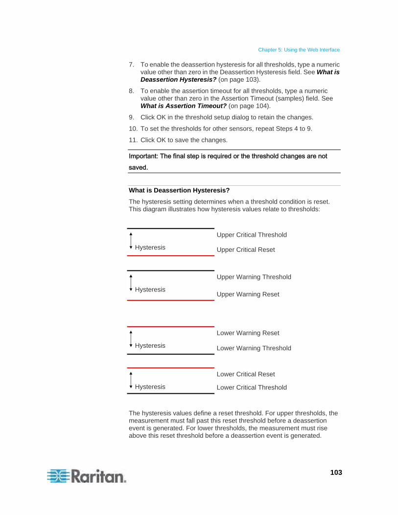
Chapter 5: Using the Web Interface
103
7. To enable the deassertion hysteresis for all thresholds, type a numeric value other than zero in the Deassertion Hysteresis field. See What is Deassertion Hysteresis? (on page 103).
8. To enable the assertion timeout for all thresholds, type a numeric value other than zero in the Assertion Timeout (samples) field. See What is Assertion Timeout? (on page 104).
9. Click OK in the threshold setup dialog to retain the changes.
10. To set the thresholds for other sensors, repeat Steps 4 to 9.
11. Click OK to save the changes.
Important: The final step is required or the threshold changes are not saved.
What is Deassertion Hysteresis?
The hysteresis setting determines when a threshold condition is reset. This diagram illustrates how hysteresis values relate to thresholds:
Upper Critical Threshold
Hysteresis Upper Critical Reset
Upper Warning Threshold
Hysteresis Upper Warning Reset
Lower Warning Reset
Hysteresis Lower Warning Threshold
Lower Critical Reset
Hysteresis Lower Critical Threshold
The hysteresis values define a reset threshold. For upper thresholds, the measurement must fall past this reset threshold before a deassertion event is generated. For lower thresholds, the measurement must rise above this reset threshold before a deassertion event is generated.
Chapter 5: Using the Web Interface
104
Example: When Hysteresis is Useful
This example demonstrates when a deassertion hysteresis is useful.
The current critical threshold for the inlet is set to 19 amps (A). The current draw rises to 20A, triggering a Current Critical alert. The current then continues to fluctuate between 18.1A and 20A.
With the hysteresis set to 1A, Raritan PXE continues to indicate that the current on the inlet is above critical. Without hysteresis (that is, the hysteresis is set to zero), Raritan PXE would de-assert the condition each time the current dropped to 18.9A, and re-assert the condition each time the current reached 19A or higher. With the fluctuating current, this could result in a number of repeating SNMP traps, and/or an e-mail account full of repeating SMTP alert notifications.
Example: When to Disable Hysteresis
This is an example of when you want to disable hysteresis for the inlet. Hysteresis is disabled if its value is set to zero.
The upper warning threshold for current in the inlet is set to 15A. In normal usage, the inlet draws 14.6A of current. A spike in demand causes the current to reach 16A, triggering an alert. The current then settles to the normal draw of 14.6A.
With the hysteresis disabled, Raritan PXE de-asserts the condition once the current drops to 14.9A. Otherwise the inlet would still be considered above the warning threshold as long as the current never dropped to 14.0A. The condition would not de-assert, even if the current returned to normal.
What is Assertion Timeout?
When the assertion timeout is enabled, the Raritan PXE device asserts any warning or critical condition only after a specified number of consecutive samples that cross a particular threshold are generated. This prevents a number of threshold alerts from being generated if the measurements return to normal immediately after rising above any upper threshold or dropping below any lower threshold.
Chapter 5: Using the Web Interface
105
Configuring Event Rules
A benefit of the product's intelligence is its ability to notify you of and react to a change in conditions. This event notification or reaction is an "event rule."
The Raritan PXE is shipped with two built-in event rules, which cannot be deleted.
System Event Log Rule: This rule causes ANY event occurred to the Raritan PXE to be recorded in the internal log. The rule is enabled by default.
System SNMP Trap Rule: This rule causes SNMP traps to be sent to specified IP addresses or hosts when ANY event occurs to the Raritan PXE. The rule is disabled by default.
If these two do not satisfy your needs, you can create additional rules to respond to different events.
Note: Internet Explorer® 8 (IE8) does not use compiled JAVA script. When using IE8 to create or change event rules, the CPU performance may be degraded, resulting in the appearance of the connection time out message. When this occurs, click Ignore to continue.
Components of an Event Rule
An event rule defines what the Raritan PXE does in certain situations and is composed of two parts:
Event: This is the situation where the Raritan PXE or part of it meets a certain condition. For example, the inlet's voltage exceeds the warning threshold.
Action: This is the response to the event. For example, the Raritan PXE notifies the system administrator of the event and records the event in the log.
Creating an Event Rule
The best way to create a new set of event rule, in sequence, is:
Create actions for responding to one or multiple events.
Create rules to determine what actions are taken when these events occur.
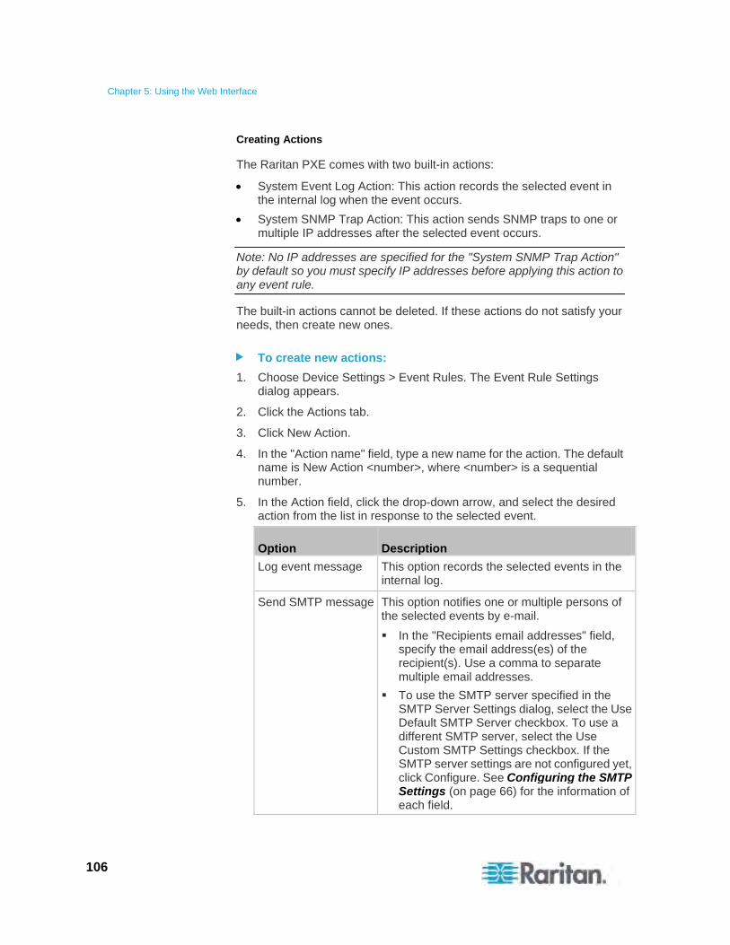
Chapter 5: Using the Web Interface
106
Creating Actions
The Raritan PXE comes with two built-in actions:
System Event Log Action: This action records the selected event in the internal log when the event occurs.
System SNMP Trap Action: This action sends SNMP traps to one or multiple IP addresses after the selected event occurs.
Note: No IP addresses are specified for the "System SNMP Trap Action" by default so you must specify IP addresses before applying this action to any event rule.
The built-in actions cannot be deleted. If these actions do not satisfy your needs, then create new ones.
To create new actions:
1. Choose Device Settings > Event Rules. The Event Rule Settings dialog appears.
2. Click the Actions tab.
3. Click New Action.
4. In the "Action name" field, type a new name for the action. The default name is New Action <number>, where <number> is a sequential number.
5. In the Action field, click the drop-down arrow, and select the desired action from the list in response to the selected event.
Option Description
Log event message This option records the selected events in the internal log.
Send SMTP message This option notifies one or multiple persons of the selected events by e-mail.
In the "Recipients email addresses" field, specify the email address(es) of the recipient(s). Use a comma to separate multiple email addresses.
To use the SMTP server specified in the SMTP Server Settings dialog, select the Use Default SMTP Server checkbox. To use a different SMTP server, select the Use Custom SMTP Settings checkbox. If the SMTP server settings are not configured yet, click Configure. See Configuring the SMTP Settings (on page 66) for the information of each field.
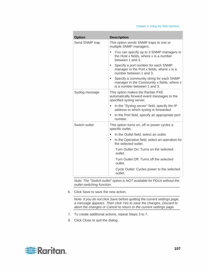
Chapter 5: Using the Web Interface
107
Option Description
Send SNMP trap This option sends SNMP traps to one or multiple SNMP managers.
You can specify up to 3 SNMP managers in the Host x fields, where x is a number between 1 and 3.
Specify a port number for each SNMP manager in the Port x fields, where x is a number between 1 and 3.
Specify a community string for each SNMP manager in the Community x fields, where x is a number between 1 and 3.
Syslog message This option makes the Raritan PXE automatically forward event messages to the specified syslog server.
In the "Syslog server" field, specify the IP address to which syslog is forwarded.
In the Port field, specify an appropriate port number.
Switch outlet This option turns on, off or power cycles a specific outlet.
In the Outlet field, select an outlet.
In the Operation field, select an operation for the selected outlet.
Turn Outlet On: Turns on the selected outlet.
Turn Outlet Off: Turns off the selected outlet.
Cycle Outlet: Cycles power to the selected outlet.
Note: The "Switch outlet" option is NOT available for PDUs without the outlet-switching function.
6. Click Save to save the new action.
Note: If you do not click Save before quitting the current settings page, a message appears. Then click Yes to save the changes, Discard to abort the changes or Cancel to return to the current settings page.
7. To create additional actions, repeat Steps 3 to 7.
8. Click Close to quit the dialog.
Chapter 5: Using the Web Interface
108
Creating Rules
After required actions are available, you can create event rules to determine what actions are taken to respond to specific events.
By default, the Raritan PXE provides two built-in event rules -- System Event Log Rule and System SNMP Trap Rule. If the built-in rules do not satisfy you needs, create new ones.
Note: For information on the built-in event rules, see Configuring Event Rules (on page 105).
To create event rules:
1. Choose Device Settings > Event Rules. The Event Rule Settings dialog appears.
2. On the Rules tab, click New Rule.
3. In the "Rule name" field, type a new name for identifying the rule. The default name is New Rule <number>, where <number> is a sequential number.
4. Select the Enabled checkbox to enable this event rule.
5. Click Event to select an event for which you want to trigger an action. A pull-down menu showing all types of events appears.
Select the desired event type from the pull-down menu, and if a submenu appears, continue the navigation until the desired event is selected.
Note: The option <Any sub-event> refers to all events/items listed on the same submenu, <Any slot> refers to all slots, <Any server> refers to all servers, and <Any user> refers to all users.
6. According to the event you selected in the previous step, the "Trigger condition" field containing three radio buttons may or may not appear.
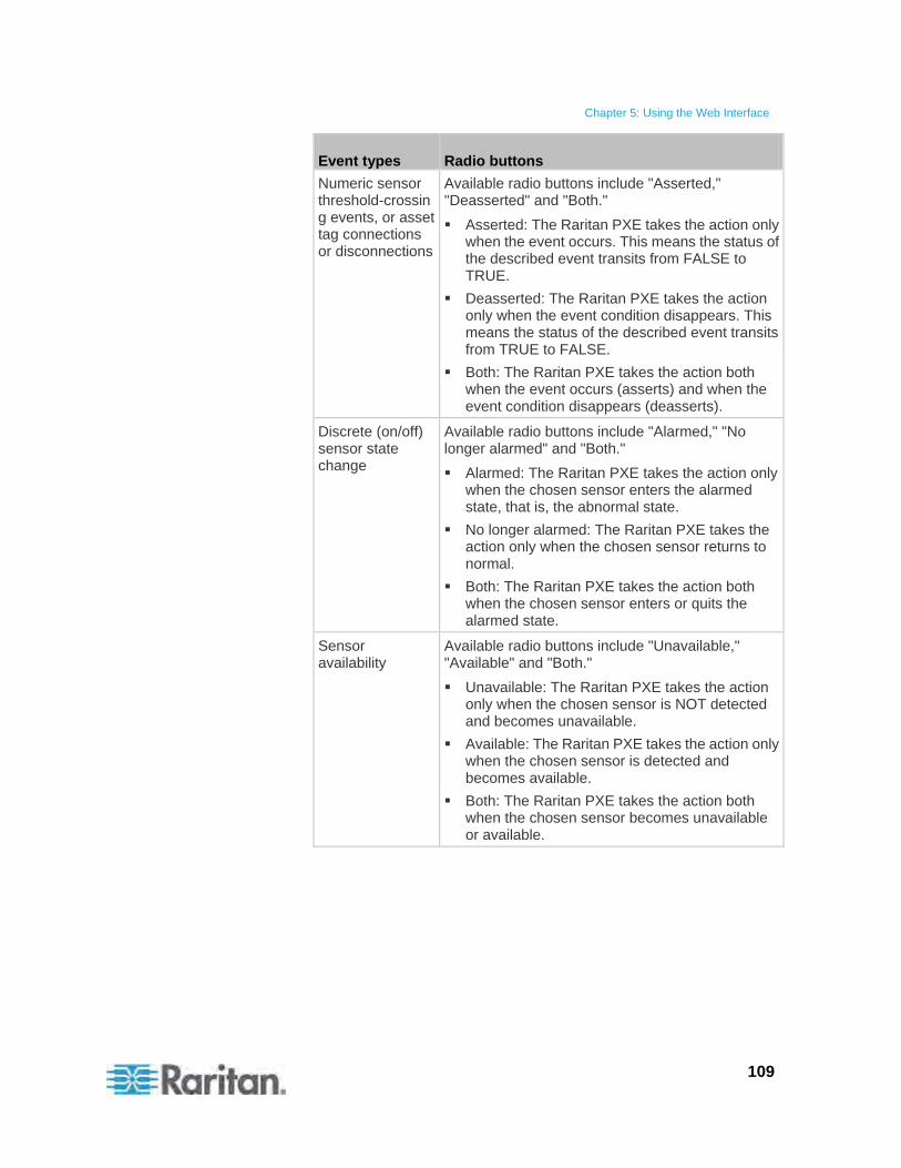
Chapter 5: Using the Web Interface
109
Event types Radio buttons
Numeric sensor threshold-crossing events, or asset tag connections or disconnections
Available radio buttons include "Asserted," "Deasserted" and "Both."
Asserted: The Raritan PXE takes the action only when the event occurs. This means the status of the described event transits from FALSE to TRUE.
Deasserted: The Raritan PXE takes the action only when the event condition disappears. This means the status of the described event transits from TRUE to FALSE.
Both: The Raritan PXE takes the action both when the event occurs (asserts) and when the event condition disappears (deasserts).
Discrete (on/off) sensor state change
Available radio buttons include "Alarmed," "No longer alarmed" and "Both."
Alarmed: The Raritan PXE takes the action only when the chosen sensor enters the alarmed state, that is, the abnormal state.
No longer alarmed: The Raritan PXE takes the action only when the chosen sensor returns to normal.
Both: The Raritan PXE takes the action both when the chosen sensor enters or quits the alarmed state.
Sensor availability
Available radio buttons include "Unavailable," "Available" and "Both."
Unavailable: The Raritan PXE takes the action only when the chosen sensor is NOT detected and becomes unavailable.
Available: The Raritan PXE takes the action only when the chosen sensor is detected and becomes available.
Both: The Raritan PXE takes the action both when the chosen sensor becomes unavailable or available.
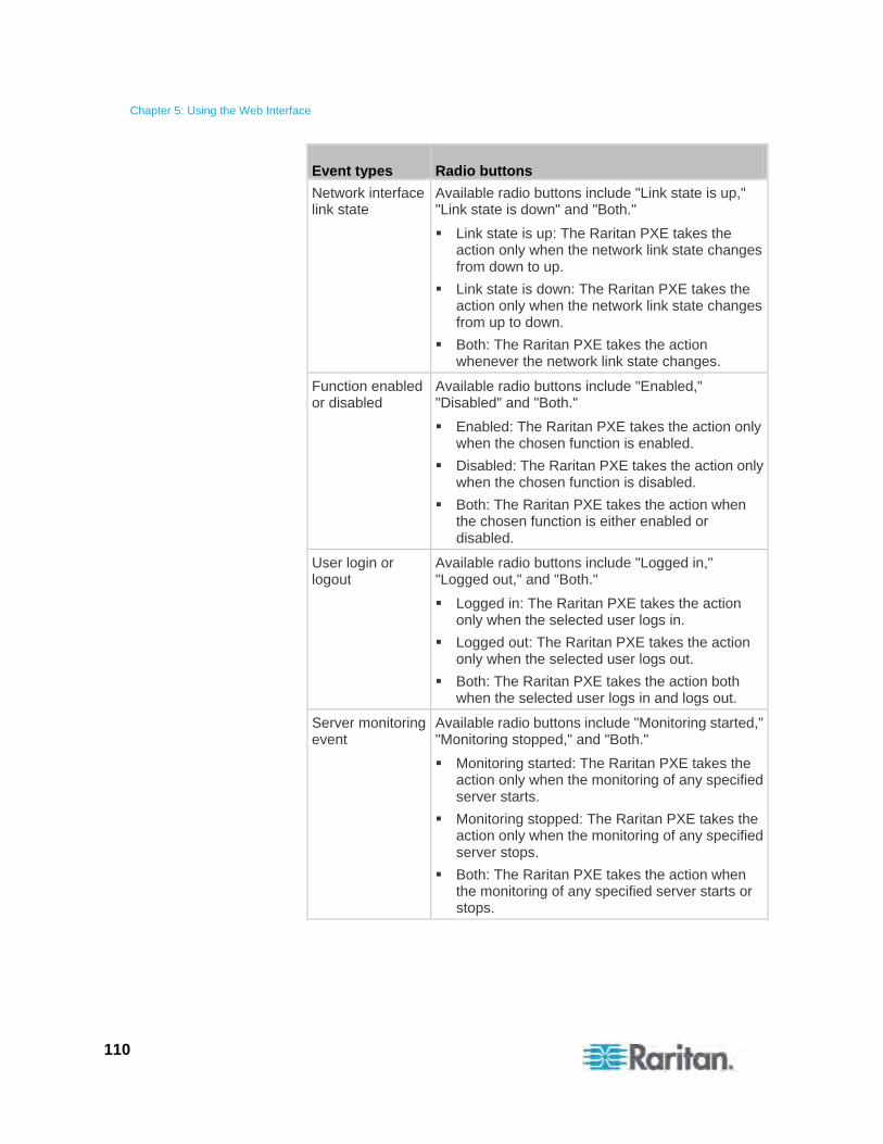
Chapter 5: Using the Web Interface
110
Event types Radio buttons
Network interface link state
Available radio buttons include "Link state is up," "Link state is down" and "Both."
Link state is up: The Raritan PXE takes the action only when the network link state changes from down to up.
Link state is down: The Raritan PXE takes the action only when the network link state changes from up to down.
Both: The Raritan PXE takes the action whenever the network link state changes.
Function enabled or disabled
Available radio buttons include "Enabled," "Disabled" and "Both."
Enabled: The Raritan PXE takes the action only when the chosen function is enabled.
Disabled: The Raritan PXE takes the action only when the chosen function is disabled.
Both: The Raritan PXE takes the action when the chosen function is either enabled or disabled.
User login or logout
Available radio buttons include "Logged in," "Logged out," and "Both."
Logged in: The Raritan PXE takes the action only when the selected user logs in.
Logged out: The Raritan PXE takes the action only when the selected user logs out.
Both: The Raritan PXE takes the action both when the selected user logs in and logs out.
Server monitoring event
Available radio buttons include "Monitoring started," "Monitoring stopped," and "Both."
Monitoring started: The Raritan PXE takes the action only when the monitoring of any specified server starts.
Monitoring stopped: The Raritan PXE takes the action only when the monitoring of any specified server stops.
Both: The Raritan PXE takes the action when the monitoring of any specified server starts or stops.

Chapter 5: Using the Web Interface
111
Event types Radio buttons
Server reachability
Available radio buttons include "Unreachable," "Reachable," and "Both."
Unreachable: The Raritan PXE takes the action only when any specified server becomes inaccessible.
Reachable: The Raritan PXE takes the action only when any specified server becomes accessible.
Both: The Raritan PXE takes the action when any specified server becomes either inaccessible or accessible.
RF Code tag connection or disconnection
Available radio buttons include "Connected," "Disconnected" and "Both."
Connected: Raritan PXE takes the action only when an RF Code tag is physically connected to it.
Disconnected: Raritan PXE takes the action only when an RF Code tag is physically disconnected from it.
Both: Raritan PXE takes the action both when the RF Code tag is physically connected to it and when it is disconnected.
Outlet power state change
Available radio buttons include "On," "Off" and "Both."
On: Raritan PXE takes the action only when the chosen outlet is turned ON.
Off: Raritan PXE takes the action only when the chosen outlet is turned OFF.
Both: Raritan PXE takes the action when the chosen outlet is either turned ON or turned OFF.
7. In the Actions field, click the drop-down arrow, select the desired
action from the list, and click the Add Action button to add the action.
The added action will be listed in the list box to the right of the Actions filed.
8. To add additional actions, repeat Step 7.
9. To remove any added action, select it from the list box, and click the
"Remove selected Action" button .
10. Click Save to save the new event rule.
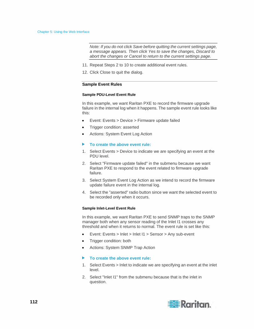
Chapter 5: Using the Web Interface
112
Note: If you do not click Save before quitting the current settings page, a message appears. Then click Yes to save the changes, Discard to abort the changes or Cancel to return to the current settings page.
11. Repeat Steps 2 to 10 to create additional event rules.
12. Click Close to quit the dialog.
Sample Event Rules
Sample PDU-Level Event Rule
In this example, we want Raritan PXE to record the firmware upgrade failure in the internal log when it happens. The sample event rule looks like this:
Event: Events > Device > Firmware update failed
Trigger condition: asserted
Actions: System Event Log Action
To create the above event rule:
1. Select Events > Device to indicate we are specifying an event at the PDU level.
2. Select "Firmware update failed" in the submenu because we want Raritan PXE to respond to the event related to firmware upgrade failure.
3. Select System Event Log Action as we intend to record the firmware update failure event in the internal log.
4. Select the "asserted" radio button since we want the selected event to be recorded only when it occurs.
Sample Inlet-Level Event Rule
In this example, we want Raritan PXE to send SNMP traps to the SNMP manager both when any sensor reading of the Inlet I1 crosses any threshold and when it returns to normal. The event rule is set like this:
Event: Events > Inlet > Inlet I1 > Sensor > Any sub-event
Trigger condition: both
Actions: System SNMP Trap Action
To create the above event rule:
1. Select Events > Inlet to indicate we are specifying an event at the inlet level.
2. Select "Inlet I1" from the submenu because that is the inlet in question.
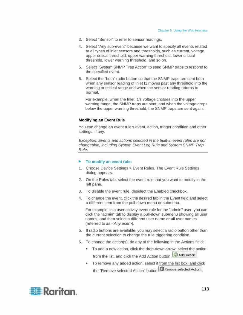
Chapter 5: Using the Web Interface
113
3. Select "Sensor" to refer to sensor readings.
4. Select "Any sub-event" because we want to specify all events related to all types of inlet sensors and thresholds, such as current, voltage, upper critical threshold, upper warning threshold, lower critical threshold, lower warning threshold, and so on.
5. Select "System SNMP Trap Action" to send SNMP traps to respond to the specified event.
6. Select the "both" radio button so that the SNMP traps are sent both when any sensor reading of Inlet I1 moves past any threshold into the warning or critical range and when the sensor reading returns to normal.
For example, when the Inlet I1's voltage crosses into the upper warning range, the SNMP traps are sent, and when the voltage drops below the upper warning threshold, the SNMP traps are sent again.
Modifying an Event Rule
You can change an event rule's event, action, trigger condition and other settings, if any.
Exception: Events and actions selected in the built-in event rules are not changeable, including System Event Log Rule and System SNMP Trap Rule.
To modify an event rule:
1. Choose Device Settings > Event Rules. The Event Rule Settings dialog appears.
2. On the Rules tab, select the event rule that you want to modify in the left pane.
3. To disable the event rule, deselect the Enabled checkbox.
4. To change the event, click the desired tab in the Event field and select a different item from the pull-down menu or submenu.
For example, in a user activity event rule for the "admin" user, you can click the "admin" tab to display a pull-down submenu showing all user names, and then select a different user name or all user names (referred to as <Any user>).
5. If radio buttons are available, you may select a radio button other than the current selection to change the rule triggering condition.
6. To change the action(s), do any of the following in the Actions field:
To add a new action, click the drop-down arrow, select the action
from the list, and click the Add Action button .
To remove any added action, select it from the list box, and click
the "Remove selected Action" button .

Chapter 5: Using the Web Interface
114
7. Click Save to save the changes.
Note: If you do not click Save before quitting the current settings page, a message appears. Then click Yes to save the changes, Discard to abort the changes or Cancel to return to the current settings page.
8. Click Close to quit the dialog.
Modifying an Action
An existing action can be changed so that all event rules where this action is involved change their behavior accordingly.
Exception: The built-in action "System Event Log Action" is not user-configurable.
To modify an action:
1. Choose Device Settings > Event Rules. The Event Rule Settings dialog appears.
2. Click the Actions tab.
3. Select the action that you want to modify from the left list.
4. Make necessary changes to the information shown.
5. Click Save to save the changes.
Note: If you do not click Save before quitting the current settings page, a message appears. Then click Yes to save the changes, Discard to abort the changes or Cancel to return to the current settings page.
6. Click Close to quit the dialog.
Deleting an Event Rule or Action
If any event rule or action is obsolete, simply remove it.
Note: You cannot delete the built-in event rules and actions.
To delete an event rule or action:
1. Choose Device Settings > Event Rules. The Event Rule Settings dialog appears.
2. To delete an event rule:
a. Ensure the Rules tab is selected. If not, click the Rules tab.
b. Select the desired rule from the left list, and click Delete Rule.
c. A message appears, prompting you to confirm the operation. Click Yes to confirm the deletion.
3. To delete an action:
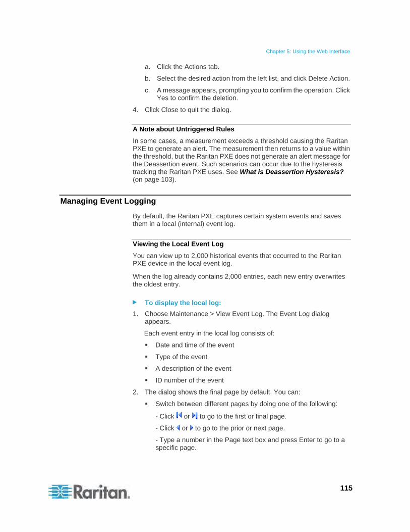
Chapter 5: Using the Web Interface
115
a. Click the Actions tab.
b. Select the desired action from the left list, and click Delete Action.
c. A message appears, prompting you to confirm the operation. Click Yes to confirm the deletion.
4. Click Close to quit the dialog.
A Note about Untriggered Rules
In some cases, a measurement exceeds a threshold causing the Raritan PXE to generate an alert. The measurement then returns to a value within the threshold, but the Raritan PXE does not generate an alert message for the Deassertion event. Such scenarios can occur due to the hysteresis tracking the Raritan PXE uses. See What is Deassertion Hysteresis? (on page 103).
Managing Event Logging
By default, the Raritan PXE captures certain system events and saves them in a local (internal) event log.
Viewing the Local Event Log
You can view up to 2,000 historical events that occurred to the Raritan PXE device in the local event log.
When the log already contains 2,000 entries, each new entry overwrites the oldest entry.
To display the local log:
1. Choose Maintenance > View Event Log. The Event Log dialog appears.
Each event entry in the local log consists of:
Date and time of the event
Type of the event
A description of the event
ID number of the event
2. The dialog shows the final page by default. You can:
Switch between different pages by doing one of the following:
- Click or to go to the first or final page.
- Click or to go to the prior or next page.
- Type a number in the Page text box and press Enter to go to a specific page.
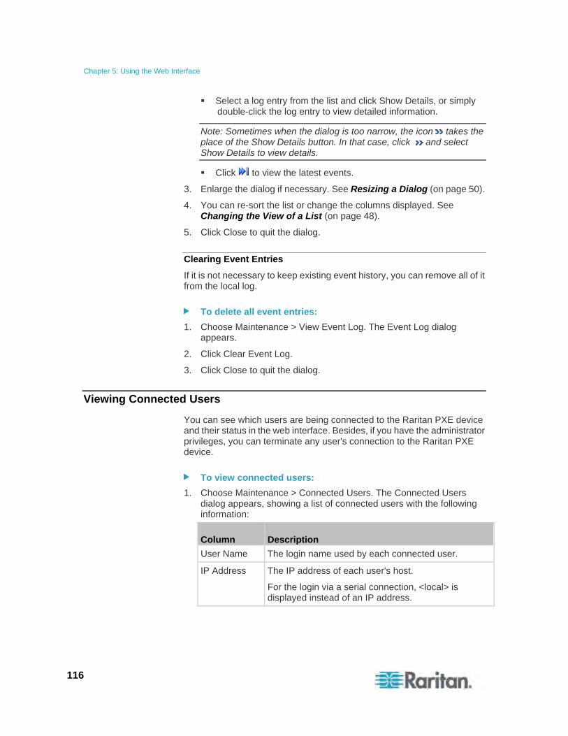
Chapter 5: Using the Web Interface
116
Select a log entry from the list and click Show Details, or simply double-click the log entry to view detailed information.
Note: Sometimes when the dialog is too narrow, the icon takes the place of the Show Details button. In that case, click and select Show Details to view details.
Click to view the latest events.
3. Enlarge the dialog if necessary. See Resizing a Dialog (on page 50).
4. You can re-sort the list or change the columns displayed. See Changing the View of a List (on page 48).
5. Click Close to quit the dialog.
Clearing Event Entries
If it is not necessary to keep existing event history, you can remove all of it from the local log.
To delete all event entries:
1. Choose Maintenance > View Event Log. The Event Log dialog appears.
2. Click Clear Event Log.
3. Click Close to quit the dialog.
Viewing Connected Users
You can see which users are being connected to the Raritan PXE device and their status in the web interface. Besides, if you have the administrator privileges, you can terminate any user's connection to the Raritan PXE device.
To view connected users:
1. Choose Maintenance > Connected Users. The Connected Users dialog appears, showing a list of connected users with the following information:
Column Description
User Name The login name used by each connected user.
IP Address The IP address of each user's host.
For the login via a serial connection, <local> is displayed instead of an IP address.
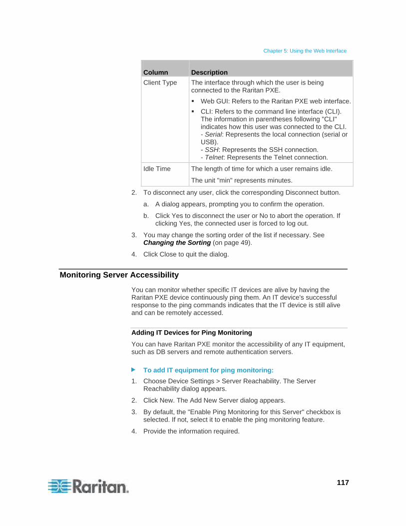
Chapter 5: Using the Web Interface
117
Column Description
Client Type The interface through which the user is being connected to the Raritan PXE.
Web GUI: Refers to the Raritan PXE web interface.
CLI: Refers to the command line interface (CLI). The information in parentheses following "CLI" indicates how this user was connected to the CLI. - Serial: Represents the local connection (serial or USB). - SSH: Represents the SSH connection. - Telnet: Represents the Telnet connection.
Idle Time The length of time for which a user remains idle.
The unit "min" represents minutes.
2. To disconnect any user, click the corresponding Disconnect button.
a. A dialog appears, prompting you to confirm the operation.
b. Click Yes to disconnect the user or No to abort the operation. If clicking Yes, the connected user is forced to log out.
3. You may change the sorting order of the list if necessary. See Changing the Sorting (on page 49).
4. Click Close to quit the dialog.
Monitoring Server Accessibility
You can monitor whether specific IT devices are alive by having the Raritan PXE device continuously ping them. An IT device's successful response to the ping commands indicates that the IT device is still alive and can be remotely accessed.
Adding IT Devices for Ping Monitoring
You can have Raritan PXE monitor the accessibility of any IT equipment, such as DB servers and remote authentication servers.
To add IT equipment for ping monitoring:
1. Choose Device Settings > Server Reachability. The Server Reachability dialog appears.
2. Click New. The Add New Server dialog appears.
3. By default, the "Enable Ping Monitoring for this Server" checkbox is selected. If not, select it to enable the ping monitoring feature.
4. Provide the information required.
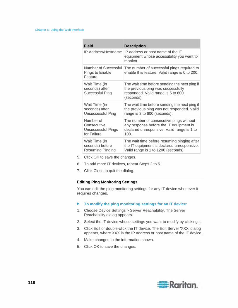
Chapter 5: Using the Web Interface
118
Field Description
IP Address/Hostname IP address or host name of the IT equipment whose accessibility you want to monitor.
Number of Successful Pings to Enable Feature
The number of successful pings required to enable this feature. Valid range is 0 to 200.
Wait Time (in seconds) after Successful Ping
The wait time before sending the next ping if the previous ping was successfully responded. Valid range is 5 to 600 (seconds).
Wait Time (in seconds) after Unsuccessful Ping
The wait time before sending the next ping if the previous ping was not responded. Valid range is 3 to 600 (seconds).
Number of Consecutive Unsuccessful Pings for Failure
The number of consecutive pings without any response before the IT equipment is declared unresponsive. Valid range is 1 to 100.
Wait Time (in seconds) before Resuming Pinging
The wait time before resuming pinging after the IT equipment is declared unresponsive. Valid range is 1 to 1200 (seconds).
5. Click OK to save the changes.
6. To add more IT devices, repeat Steps 2 to 5.
7. Click Close to quit the dialog.
Editing Ping Monitoring Settings
You can edit the ping monitoring settings for any IT device whenever it requires changes.
To modify the ping monitoring settings for an IT device:
1. Choose Device Settings > Server Reachability. The Server Reachability dialog appears.
2. Select the IT device whose settings you want to modify by clicking it.
3. Click Edit or double-click the IT device. The Edit Server 'XXX' dialog appears, where XXX is the IP address or host name of the IT device.
4. Make changes to the information shown.
5. Click OK to save the changes.
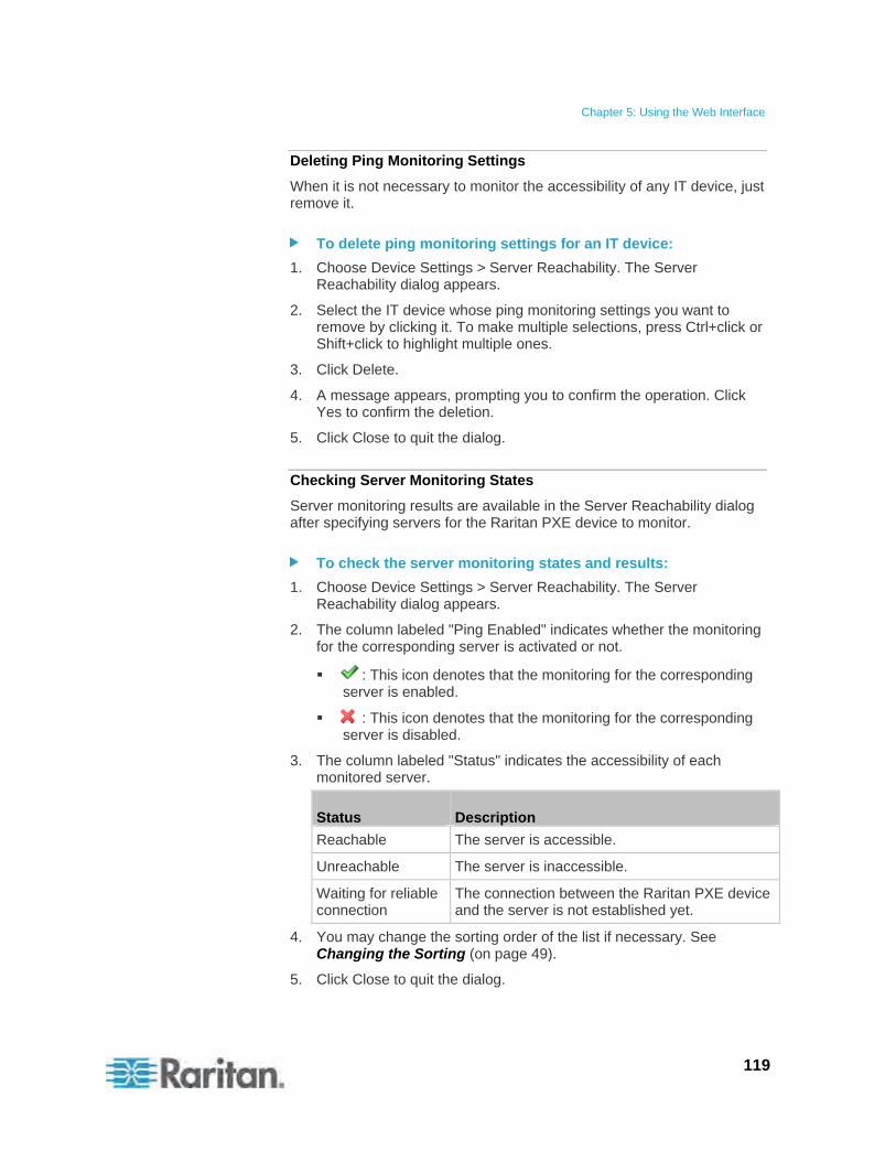
Chapter 5: Using the Web Interface
119
Deleting Ping Monitoring Settings
When it is not necessary to monitor the accessibility of any IT device, just remove it.
To delete ping monitoring settings for an IT device:
1. Choose Device Settings > Server Reachability. The Server Reachability dialog appears.
2. Select the IT device whose ping monitoring settings you want to remove by clicking it. To make multiple selections, press Ctrl+click or Shift+click to highlight multiple ones.
3. Click Delete.
4. A message appears, prompting you to confirm the operation. Click Yes to confirm the deletion.
5. Click Close to quit the dialog.
Checking Server Monitoring States
Server monitoring results are available in the Server Reachability dialog after specifying servers for the Raritan PXE device to monitor.
To check the server monitoring states and results:
1. Choose Device Settings > Server Reachability. The Server Reachability dialog appears.
2. The column labeled "Ping Enabled" indicates whether the monitoring for the corresponding server is activated or not.
: This icon denotes that the monitoring for the corresponding server is enabled.
: This icon denotes that the monitoring for the corresponding server is disabled.
3. The column labeled "Status" indicates the accessibility of each monitored server.
Status Description
Reachable The server is accessible.
Unreachable The server is inaccessible.
Waiting for reliable connection
The connection between the Raritan PXE device and the server is not established yet.
4. You may change the sorting order of the list if necessary. See Changing the Sorting (on page 49).
5. Click Close to quit the dialog.
Chapter 5: Using the Web Interface
120
Environmental Sensors
The Raritan PXE can monitor the environmental conditions, such as temperature and humidity, where environmental sensors are placed.
To add environmental sensors:
1. Physically connect environmental sensors to the Raritan PXE device. See Connecting Environmental Sensors (Optional) (on page 22).
2. Log in to the Raritan PXE web interface. The Raritan PXE should have detected the connected sensors, and display them in the web interface.
3. Identify each sensor through the sensor's serial number. See Identifying Environmental Sensors (on page 121).
4. The Raritan PXE should automatically manage the detected sensors. Verify whether detected sensors are managed. If not, have them managed. See Managing Environmental Sensors (on page 122).
5. Configure the sensors. See Configuring Environmental Sensors (on page 123). The steps include:
a. Name the sensor.
b. If the connected sensor is a Raritan contact closure sensor, specify an appropriate sensor type.
c. Mark the sensor's physical location in the rack or server room.
d. For a numeric sensor, configure the sensor's threshold, hysteresis and assertion timeout settings.
Note: Numeric sensors use numeric values to indicate the environmental or internal conditions while discrete (on/off) sensors use alphabetical characters to indicate the state. Only numeric sensors have the threshold settings.

Chapter 5: Using the Web Interface
121
Identifying Environmental Sensors
An environmental sensor includes a serial number tag on the sensor cable.
The serial number for each sensor appears listed in the web interface after each sensor is detected by the Raritan PXE.
To identify each detected environmental sensor:
1. If the PDU folder is not expanded, expand it to show all components and component groups. See Expanding the Tree (on page 42).
Note: The PDU folder is named "my PX" by default. The name changes after customizing the device name. See Naming the PDU (on page 53).
2. Click External Sensors in the Dominion PX Explorer pane, and the External Sensors page opens in the right pane.
3. Match the serial number from the tag to those listed in the sensor table.
Chapter 5: Using the Web Interface
122
Managing Environmental Sensors
The Raritan PXE starts to retrieve an environmental sensor's reading and/or state and records the state transitions after the environmental sensor is managed.
The Raritan PXE device can manage a maximum of 16 environmental sensors.
When there are less than 16 managed sensors, the Raritan PXE automatically brings detected environmental sensors under management. You should only have to manually manage a sensor when it is not under management.
To manually manage an environmental sensor:
1. If the PDU folder is not expanded, expand it to show all components and component groups. See Expanding the Tree (on page 42).
Note: The PDU folder is named "my PX" by default. The name changes after customizing the device name. See Naming the PDU (on page 53).
2. Click External Sensors in the Dominion PX Explorer pane, and the External Sensors page opens in the right pane.
3. Click the sensor you want to manage on the External Sensors page.
Note: To identify all detected sensors, see Identifying Environmental Sensors (on page 121).
4. Click Manage. The "Manage sensor <serial number> (<sensor type>)" dialog appears, where <serial number> is the sensor's serial number and <sensor type> is the sensor's type.
Note: For a contact closure sensor, a channel number is added to the end of the <sensor type>.
5. There are two ways to manage the sensor:
To manage this sensor by letting the Raritan PXE assign a number to it, select "Automatically assign a sensor number." This method does not release any managed sensors.
To manage this sensor by assigning the number you want to it, select "Manually select a sensor number." Then click the drop-down arrow to select a number.
If the number you selected was already assigned to a sensor, that sensor becomes released after losing this ID number.
Chapter 5: Using the Web Interface
123
Tip: The information in parentheses following each ID number indicates whether the number has been assigned to any sensor. If it has been assigned to a sensor, it shows that sensor's serial number. Otherwise, it shows the term "unused."
6. Click OK. The Raritan PXE starts to track and display the managed sensor's reading and/or state.
7. To manage additional sensors, repeat Steps 3 to 6.
Note: When the number of managed sensors reaches the maximum, you CANNOT manage additional sensors until you remove or replace any managed sensors. To remove a sensor, see Unmanaging Environmental Sensors (on page 129).
Configuring Environmental Sensors
You may change the default name for easily identifying the managed sensor, and describe its location with X, Y and Z coordinates.
To configure environmental sensors:
1. If the PDU folder is not expanded, expand it to show all components and component groups. See Expanding the Tree (on page 42).
Note: The PDU folder is named "my PX" by default. The name changes after customizing the device name. See Naming the PDU (on page 53).
2. Click External Sensors in the Dominion PX Explorer pane, and the External Sensors page opens in the right pane.
3. Select the sensor that you want to configure.
4. Click Setup. The "Setup of external sensor <serial number> (<sensor type>)" dialog appears, where <serial number> is the serial number of this sensor and <sensor type> is the sensor's type.
Tip: You can also trigger the same setup dialog by selecting the desired environmental sensor icon in the tree and then clicking Setup on that sensor's page opened in the right pane.
5. If the selected environmental sensor is the Raritan contact closure sensor connected with a third-party detector/switch, select the appropriate sensor type in the Binary Sensor Subtype field.
Contact: The detector/switch is designed to detect the door lock or door open/closed status.
Smoke Detection: The detector/switch is designed to detect the appearance of smoke.
Water Detection: The detector/switch is designed to detect the appearance of water on the floor.
Chapter 5: Using the Web Interface
124
Vibration: The detector/switch is designed to detect the vibration in the floor.
6. Type a new name in the Name field.
7. Describe the sensor's location by assigning alphanumeric values to the X, Y and Z coordinates. See Describing the Sensor Location (on page 125).
Note: When the term "Rack Units" appears inside the parentheses in the Z location field, indicating that the Z coordinate format is set to Rack Units, you must type an integer number.
8. If the selected environmental sensor is a numeric sensor, its threshold settings are displayed in the dialog. Click Edit or double-click the Threshold Configuration table to adjust the threshold, deassertion hysteresis and assertion timeout settings.
To enable any threshold, select the corresponding checkbox. To disable a threshold, deselect the checkbox.
After any threshold is enabled, type an appropriate numeric value in the accompanying text box.
To enable the deassertion hysteresis for all thresholds, type a numeric value other than zero in the Deassertion Hysteresis field. See What is Deassertion Hysteresis? (on page 103).
To enable the assertion timeout for all thresholds, type a numeric value other than zero in the Assertion Timeout (samples) field. See What is Assertion Timeout? (on page 104).
Note: The Upper Critical and Lower Critical values are points at which the Raritan PXE considers the operating environment critical and outside the range of the acceptable threshold.
9. Click OK to save the changes.
10. Repeat Steps 3 through 9 to configure additional environmental sensors.
Setting the Z Coordinate Format
You can use either the number of rack units or a descriptive text to describe the vertical locations (Z coordinates) of environmental sensors.
To determine the Z coordinate format:
1. Click the PDU folder.
Note: The PDU folder is named "my PX" by default. The name changes after customizing the device name. See Naming the PDU (on page 53).
2. Click Setup in the Settings section. The Pdu Setup dialog appears.
Chapter 5: Using the Web Interface
125
3. In the "External sensors Z coordinate format" field, click the drop-down arrow and select an option from the list.
Rack Units: The height of the Z coordinate is measured in standard rack units. When this is selected, you can type a numeric value in the rack unit to describe the Z coordinate of any environmental sensors.
Free-Form: Any alphanumeric string can be used for specifying the Z coordinate.
4. Click OK to save the changes.
Describing the Sensor Location
Use the X, Y and Z coordinates to describe each sensor's physical location. You can use these location values to track records of environmental conditions in fixed locations around your IT equipment. The X, Y and Z values act as additional attributes and are not tied to any specific measurement scheme. If you choose to, you can use non-measurement values. For example:
X = Brown Cabinet Row
Y = Third Rack
Z = Top of Cabinet
Values for the X, Y and Z coordinates may consist of:
For X and Y: Any combination of alphanumeric characters. The coordinate value can be 0 to 32 characters long.
For Z when the Z coordinate format is set to Rack Units, any numeric value ranging from 0 to 60.
For Z when the Z coordinate format is set to Free-Form, any alphanumeric characters from 0 to 32 characters.
Tip: To configure and retrieve these coordinate values over SNMP, see the Raritan PXE MIB. To configure and retrieve these values over the CLI, see Using the Command Line Interface (on page 148).
Chapter 5: Using the Web Interface
126
Viewing Sensor Data
Readings of the environmental sensors will display in the web interface after these sensors are properly connected and managed.
The Dashboard page shows the information for managed environmental sensors only, while the External Sensors page shows the information for both of managed and unmanaged ones.
If a sensor reading row is colored, it means the sensor reading already crosses one of the thresholds, or the circuit breaker has tripped. See The Yellow- or Red-Highlighted Reading (on page 47).
To view managed environmental sensors only:
1. Click the Dashboard icon in the Dominion PX Explorer pane, and the Dashboard page opens in the right pane.
2. Locate the External Sensors section on the Dashboard page. The section shows:
Total number of managed sensors
Total number of unmanaged sensors
Information of each managed sensor, including:
- Name
- Reading
- State
To view both of managed and unmanaged environmental sensors:
1. If the PDU folder is not expanded, expand it to show all components and component groups. See Expanding the Tree (on page 42).
Note: The PDU folder is named "my PX" by default. The name changes after customizing the device name. See Naming the PDU (on page 53).
2. Click External Sensors in the Dominion PX Explorer pane, and the External Sensors page opens in the right pane.
Detailed information for each connected sensor is displayed, including:
Label (number)
Serial number
Sensor type
Name
Reading
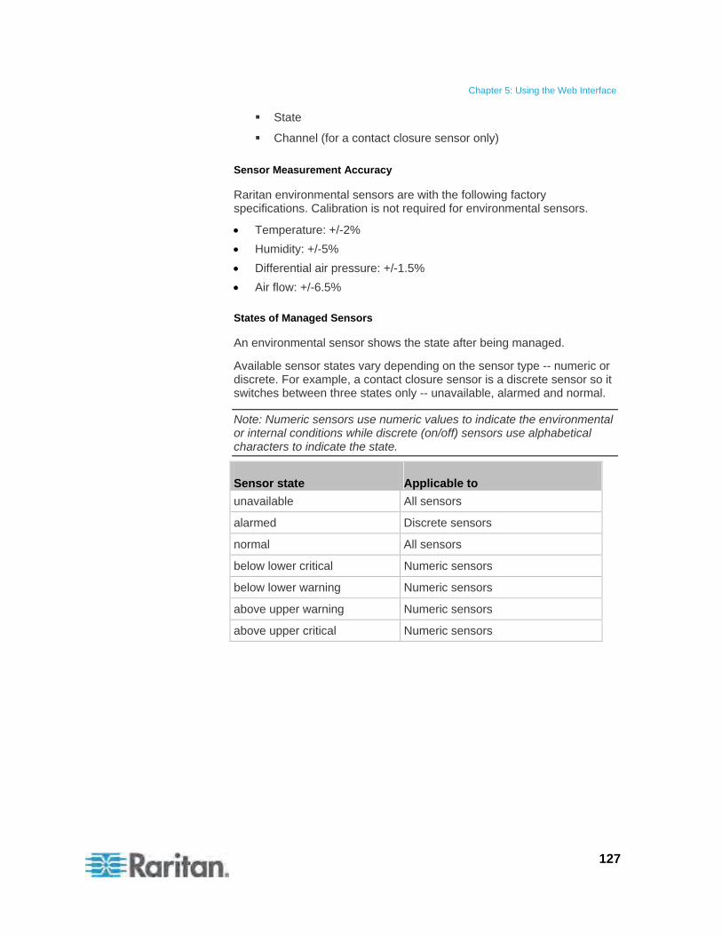
Chapter 5: Using the Web Interface
127
State
Channel (for a contact closure sensor only)
Sensor Measurement Accuracy
Raritan environmental sensors are with the following factory specifications. Calibration is not required for environmental sensors.
Temperature: +/-2%
Humidity: +/-5%
Differential air pressure: +/-1.5%
Air flow: +/-6.5%
States of Managed Sensors
An environmental sensor shows the state after being managed.
Available sensor states vary depending on the sensor type -- numeric or discrete. For example, a contact closure sensor is a discrete sensor so it switches between three states only -- unavailable, alarmed and normal.
Note: Numeric sensors use numeric values to indicate the environmental or internal conditions while discrete (on/off) sensors use alphabetical characters to indicate the state.
Sensor state Applicable to
unavailable All sensors
alarmed Discrete sensors
normal All sensors
below lower critical Numeric sensors
below lower warning Numeric sensors
above upper warning Numeric sensors
above upper critical Numeric sensors
Chapter 5: Using the Web Interface
128
"unavailable" State
The unavailable state means the connectivity to the sensor is lost.
The Raritan PXE pings all managed sensors at regular intervals in seconds. If it does not detect a particular sensor for three consecutive scans, the unavailable state is displayed for that sensor.
When the communication with a contact closure sensor's processor is lost, all detectors (that is, all switches) connected to the same sensor module show the "unavailable" state.
Note: When the sensor is deemed unavailable, the existing sensor configuration remains unchanged. For example, the ID number assigned to the sensor remains associated with it.
The Raritan PXE continues to ping unavailable sensors, and moves out of the unavailable state after detecting the sensor for two consecutive scans.
"normal" State
This state indicates the sensor is in the normal state.
For a contact closure sensor, this state is the normal state you have set.
If the normal state is set to Normally Closed, the normal state means the contact closure switch is closed.
If the normal state is set to Normally Open, the normal state means the contact closure switch is open.
Note: See Configuring a Contact Closure Sensor (on page 25) for setting the normal state.
For a numeric sensor, this state means the sensor reading is within the acceptable range as indicated below:
Lower Warning threshold <= Reading < Upper Warning threshold
Note: The symbol <= means smaller than (<) or equal to (=).
"alarmed" State
This state means a discrete (on/off) sensor is in the "abnormal" state.
For a contact closure sensor, the meaning of this state varies based on the sensor's normal state setting.
If the normal state is set to Normally Closed, the alarmed state means the contact closure switch is open.
If the normal state is set to Normally Open, the alarmed state means the contact closure switch is closed.
Note: See Configuring a Contact Closure Sensor (on page 25) for setting the normal state.
Chapter 5: Using the Web Interface
129
Tip: A contact closure sensor's LED is lit after entering the alarmed state. If the sensor module has two channels for connecting two switches, two LEDs are available. Check which contact closure switch is in the "abnormal" status according to the channel number of the LED.
"below lower critical" State
This state means a numeric sensor's reading is below the lower critical threshold as indicated below:
Reading < Lower Critical Threshold
"below lower warning" State
This state means a numeric sensor's reading is below the lower warning threshold as indicated below:
Lower Critical Threshold <= Reading < Lower Warning Threshold
Note: The symbol <= means smaller than (<) or equal to (=).
"above upper warning" State
This state means a numeric sensor's reading is above the upper warning threshold as indicated below:
Upper Warning Threshold <= Reading < Upper Critical Threshold
Note: The symbol <= means smaller than (<) or equal to (=).
"above upper critical" State
This state means a numeric sensor's reading is above the upper critical threshold as indicated below:
Upper Critical Threshold <= Reading
Note: The symbol <= means smaller than (<) or equal to (=).
Unmanaging Environmental Sensors
When it is unnecessary to monitor a particular environmental factor, you can unmanage or release the corresponding environmental sensor so that the Raritan PXE device stops retrieving the sensor's reading and/or state.
To release a managed sensor:
1. If the PDU folder is not expanded, expand it to show all components and component groups. See Expanding the Tree (on page 42).
Note: The PDU folder is named "my PX" by default. The name changes after customizing the device name. See Naming the PDU (on page 53).

Chapter 5: Using the Web Interface
130
2. Click External Sensors in the Dominion PX Explorer pane, and the External Sensors page opens in the right pane.
3. Click the sensor you want to unmanage on the External Sensors page.
4. Click Release.
After a sensor is removed from management, the ID number assigned to that sensor is released and can be automatically assigned to any newly-detected sensor.
Copying Configurations with Bulk Configuration
The Bulk Configuration feature lets you save the settings of a configured Raritan PXE device to your PC. You can use this configuration file to:
Copy that configuration to other Raritan PXE devices of the same model.
Restore the settings of the same Raritan PXE device to previous configuration.
You must have the Administrator Privileges to save and copy the Raritan PXE configurations.
Chapter 5: Using the Web Interface
131
Saving a Raritan PXE Configuration
A source device is an already configured Raritan PXE device that is used to create a configuration file containing the settings that can be shared between Raritan PXE devices. These settings include user and role configurations, thresholds, event rules, security settings, and so on.
This file does NOT contain device-specific information, including:
Device name
System name, system contact and system location
Network settings (IP address, gateway, netmask and so on)
Device logs
Outlet names
Outlet status
Environmental sensor names
Environmental sensor states and values
SSL certificate
Because the date and time settings are saved in the configuration file, users should exercise caution when distributing the configuration file to the Raritan PXE devices in a different time zone than the source device.
To save a configuration file:
1. Choose Maintenance > Bulk Configuration. The Bulk Configuration dialog appears.
2. Click Download Bulk Configuration.
3. When the web browser prompts you to open or save the configuration file, click Save. Choose a suitable location and save the configuration file to your PC.
The file is saved in the XML format, and its content is encrypted using the AES-128 encryption algorithm.
Chapter 5: Using the Web Interface
132
Copying a Raritan PXE Configuration
A target device is a Raritan PXE device that loads another Raritan PXE device's configuration file.
Copying a Raritan PXE configuration to a target device adjusts that Raritan PXE device's settings to match those of the source Raritan PXE device. In order to successfully copy a Raritan PXE configuration:
The user must be the Admin user. Or the Admin role is assigned to the user.
The target Raritan PXE device must be of the same model type as the source Raritan PXE device.
The target Raritan PXE device must be running the same firmware version as the source Raritan PXE device.
To copy a Raritan PXE Configuration:
1. Log in to the target device's web interface.
2. If the target device's firmware version does not match that of the source device, update the target's firmware. See Firmware Upgrade (on page 136).
3. Choose Maintenance > Bulk Configuration. The Bulk Configuration dialog appears.
4. In the Copy Bulk Configuration section, click Browse and select the configuration file stored on your PC.
5. Click Upload & Restore Bulk Configuration to copy the file.
6. A message appears, prompting you to confirm the operation. Click Yes to confirm the operation.
7. Wait until the Raritan PXE device resets and the Login page re-appears, indicating that the configuration copy is complete.
Changing the Measurement Units
By default, the following measurement units are applied to all data shown in the Raritan PXE web interface:
Temperature: degrees in Celsius ( )
Length or height: meters (m)
Air pressure: pascal (pa)
The Raritan PXE web interface allows shows different measurement units based on the login name. That is, different users may see different measurement units displayed according to their preferences. The other alternatives for each measurement unit include:
Temperature: degrees in Fahrenheit ( )
Chapter 5: Using the Web Interface
133
Length or height: feet (ft)
Air pressure: psi
To change the measurement unit setting, you must have the administrator privileges.
To set the preferred measurement units:
1. Choose User Management > Users. The Manage Users dialog appears.
2. Select the user by clicking it.
3. Click Edit or double-click the user. The Edit User 'XXX' dialog appears, where XXX is the user name.
4. Click the Preferences tab.
5. To change the temperature unit, select the desired option in the Temperature Unit field.
: This option displays the temperature in Celsius.
: This option displays the temperature in Fahrenheit.
6. To change the length or height unit, select the desired option in the Length Unit field.
Meter: This option displays the length or height in meters.
Feet: This option displays the length or height in feet.
7. To change the pressure unit, select the desired option in the Pressure Unit field.
Pascal: This option displays the pressure value in Pascals (Pa). A Pascal is equal to one newton per square meter.
psi: This option displays the pressure value in psi. Psi stands for pounds per square inch.
8. Click OK to save the changes.
Tip: You can determine the desired measurement unit when creating user profiles. See Creating a User Profile (on page 68).
Chapter 5: Using the Web Interface
134
Network Diagnostics
The Raritan PXE provides the following tools in the web interface for diagnosing potential networking issues.
Ping
Trace Route
List TCP Connections
Tip: These network diagnostic tools are also available through CLI. See Network Troubleshooting (on page 251).
Pinging a Host
The Ping tool is useful for checking whether a host is accessible through the network or Internet.
To ping a host:
1. Choose Maintenance > Network Diagnostics > Ping. The Ping Network Host dialog appears.
2. In the Host Name field, type the name or IP address of the host that you want to check.
3. In the Number of Requests field, type a number up to 10 or adjust the value by clicking either arrow. This number determines how many packets are sent for pinging the host.
4. Click Run Ping to start pinging the host. A dialog appears, displaying the Ping results.
5. Click Close to quit the dialog.
Tracing the Network Route
Trace Route lets you find out the route over the network between two hosts or systems.
To trace the route for a host:
1. Choose Maintenance > Network Diagnostics > Trace Route. The Trace Route to Host dialog appears.
2. Type the IP address or name of the host whose route you want to check in the Host Name field.
3. Click Run. A dialog appears, displaying the Trace Route results.
4. Click Close to quit the dialog.

Chapter 5: Using the Web Interface
135
Listing TCP Connections
You can use the "List TCP Connections" to display a list of TCP connections.
To trace the route for a host:
1. Choose Maintenance > Network Diagnostics > List TCP Connections. The TCP connections dialog appears.
2. Click Close to quit the dialog.
Viewing the Communication Log
The Raritan PXE allows you to inspect all communications occurred between the Raritan PXE device and its graphical user interface (GUI). The information is usually useful for a technical support engineer only and you may not need to view it.
This feature is accessible only by users with Administrative Privileges.
To view the communication log:
1. Choose Maintenance > View Communication Log. The Communication Log dialog appears.
2. The dialog shows the final page by default. You can:
Switch between different pages by doing one of the following:
- Click or to go to the first or final page.
- Click or to go to the prior or next page.
- Type a number in the Page text box and press Enter to go to a specific page.
Select a log entry from the list and click Show Details, or simply double-click the log entry to view detailed information.
Note: Sometimes when the dialog is too narrow, the icon takes the place of the Show Details button. In that case, click and select Show Details to view details.
3. To immediately update the communication log, click .
4. To save the communication log on your computer, click .
5. Enlarge the dialog if necessary. See Resizing a Dialog (on page 50).
6. You can re-sort the list or change the columns displayed. See Changing the View of a List (on page 48).
7. Click Close to quit the dialog.

Chapter 5: Using the Web Interface
136
Downloading Diagnostic Information
This function is for use by Raritan Field Engineers or when you are directed by Raritan Technical Support.
You can download the diagnostic file from the Raritan PXE device to a client machine. The file is compressed into a .tgz file and should be sent to Raritan Technical Support for interpretation.
This feature is accessible only by users with Administrative Privileges.
To retrieve a diagnostic file:
1. Choose Maintenance > Download Diagnostic Information. The File Download dialog appears.
2. Click Save. The Save As dialog appears.
3. Navigate to the desired directory and click Save.
4. E-mail this file as instructed by Raritan Technical Support.
Firmware Upgrade
You may upgrade your Raritan PXE device to benefit from the latest enhancements, improvements and features.
The Raritan PXE firmware files are available on the Raritan website's Firmware and Documentation section (http://www.raritan.com/support/firmware-and-documentation/).

Chapter 5: Using the Web Interface
137
Updating the Raritan PXE Firmware
You must be the system administrator or log in to the user profile with the Firmware Update permission to update the Raritan PXE device's firmware.
If applicable to your model, download the latest firmware file from the Raritan website, read the release notes, then start the upgrade. If you have any questions or concerns about the upgrade, contact Raritan Technical Support BEFORE upgrading.
Warning: Do NOT perform the firmware upgrade over a wireless connection.
To update the firmware:
1. Choose Maintenance > Update Firmware. The Firmware Update dialog appears.
2. In the Firmware File field, click Browse to select an appropriate firmware file.
3. Click Upload. A progress bar appears to indicate the upload status.
4. When the upload is complete, version information of both the existing firmware and uploaded firmware is shown, providing you a last chance to terminate the update.
5. To view the certificate of the uploaded firmware, click View Certificate. Optional.
6. To proceed with the update, click Update Firmware. The update may take several minutes.
Warning: Do NOT power off the Raritan PXE device during the update.
During the firmware update:
A progress bar appears in the web interface, indicating the update status.
On the Raritan PXE device, the three-digit LED display shows “FUP.”
No users can successfully log in to the Raritan PXE.
In the web interface, all logged-in users see the Raritan PXE time out message, and the "disconnected" state is shown in the status bar.
The user management operation, if any, is forced to suspend.
7. When the update is complete, a message appears, indicating the update is successful.
Chapter 5: Using the Web Interface
138
8. The Raritan PXE device resets, and the Login page re-appears. You can now log in and resume your operation.
Note 1: The other logged-in users are also logged out when the firmware update is complete.
Note 2: If you are using the Raritan PXE with an SNMP manager, you should re-download the Raritan PXE MIB after the firmware update. This ensures your SNMP manager has the correct MIB for the latest release you are using. See Using SNMP (on page 142).
A Note about Firmware Upgrade Time
The PDU firmware upgrade time varies from unit to unit, depending on various external and internal factors.
External factors include, but are not limited to: network throughput, firmware file size, and speed at which the firmware is retrieved from the storage location. Internal factors include: the necessity of upgrading the firmware on the microcontroller and the number of microcontrollers that require upgrade (which depends on the number of outlets). The microcontroller is upgraded only when required. Therefore, the length of firmware upgrade time ranges from approximately 3 minutes (without any microcontroller updated) to almost 7 minutes (with all microcontrollers for 48 outlets updated). Take the above factors into account when estimating the PDU's firmware upgrade time.
The time indicated in this note is for web-interface-based upgrades. Upgrades through other management systems, such as Raritan's Power IQ, may take additional time beyond the control of the PDU itself. This note does not address the upgrades using other management systems.
Viewing Firmware Update History
The firmware upgrade history, if available, is permanently stored on the Raritan PXE device.
This history indicates when a firmware upgrade event occurred, the prior and new versions associated with the firmware upgrade event, and the upgrade result.
To view the firmware update history:
1. Choose Maintenance > View Firmware Update History. The Firmware Update History dialog appears, with the following information displayed.
Date and time of the firmware upgrade event
Previous firmware version
Chapter 5: Using the Web Interface
139
Update firmware version
Firmware upgrade result
2. You may change the number of displayed columns or re-sort the list for better viewing the data. See Changing the View of a List (on page 48).
3. To view the details of any firmware upgrade event, select it and click Details, or simply double-click the event. The Firmware Update Details dialog appears, showing detailed information of the selected event.
4. Click Close to quit the dialog.
Full Disaster Recovery
If the firmware upgrade fails, causing the Raritan PXE device to stop working, you can recover it by using a special utility rather than returning the device to Raritan.
Contact Raritan Technical Support for the recovery utility, which works in Windows XP/Vista/7 and Linux. In addition, an appropriate Raritan PXE firmware file is required in the recovery procedure.
Accessing the Help
The Help menu provides:
Current firmware and software packages information
A link to the Raritan PXE User Guide (that is, the online help)
Retrieving Software Packages Information
You can check the current firmware version and the information of all open source packages embedded in the Raritan PXE device through the web interface.
To retrieve the embedded software packages information:
1. Choose Help > About Dominion PX. The About Dominion PX dialog appears, with a list of open source packages displayed.
2. You can click any link in the dialog to access related information or download any software package.
Chapter 5: Using the Web Interface
140
Browsing through the Online Help
The Raritan PXE User Guide is also provided in the form of online help, and accessible over the Internet.
To use online help, Active Content must be enabled in your browser. If you are using Internet Explorer 7, you must enable Scriplets. Consult your browser help for information on enabling these features.
To use the Raritan PXE online help:
1. Choose Help > User Guide. The online help opens in the default web browser.
2. To view the content of any topic, click the topic in the left pane. Then its content is displayed in the right pane.
3. To select a different topic, do any of the following:
To view the next topic, click the Next icon in the toolbar.
To view the previous topic, click the Previous icon .
To view the first topic, click the Home icon .
4. To expand or collapse a topic that contains sub-topics, do the following:
To expand any topic, click the white arrow prior to the topic, or double-click that topic. The arrow turns into a black, gradient arrow , and sub-topics appear below the topic.
To collapse any expanded topic, click the black, gradient arrow prior to the topic, or double-click the expanded topic. The arrow then turns into a white arrow , and all sub-topics below that topic disappear.
5. To search for specific information, type the key word(s) or string(s) in the Search text box, and press Enter or click the Search icon to start the search.
If necessary, select the "Match partial words" checkbox to include information matching part of the words entered in the Search text box.
The search results are displayed in the left pane.
6. To have the left pane show the list of topics, click the Contents tab at the bottom.
7. To show the Index page, click the Index tab.
8. To email any URL link to the currently selected topic to any person,
click the "Email this page" icon in the toolbar.
Chapter 5: Using the Web Interface
141
9. To email your comments or suggestions regarding the user guide to
Raritan, click the "Send feedback" icon .
10. To print the currently selected topic, click the "Print this page" icon .
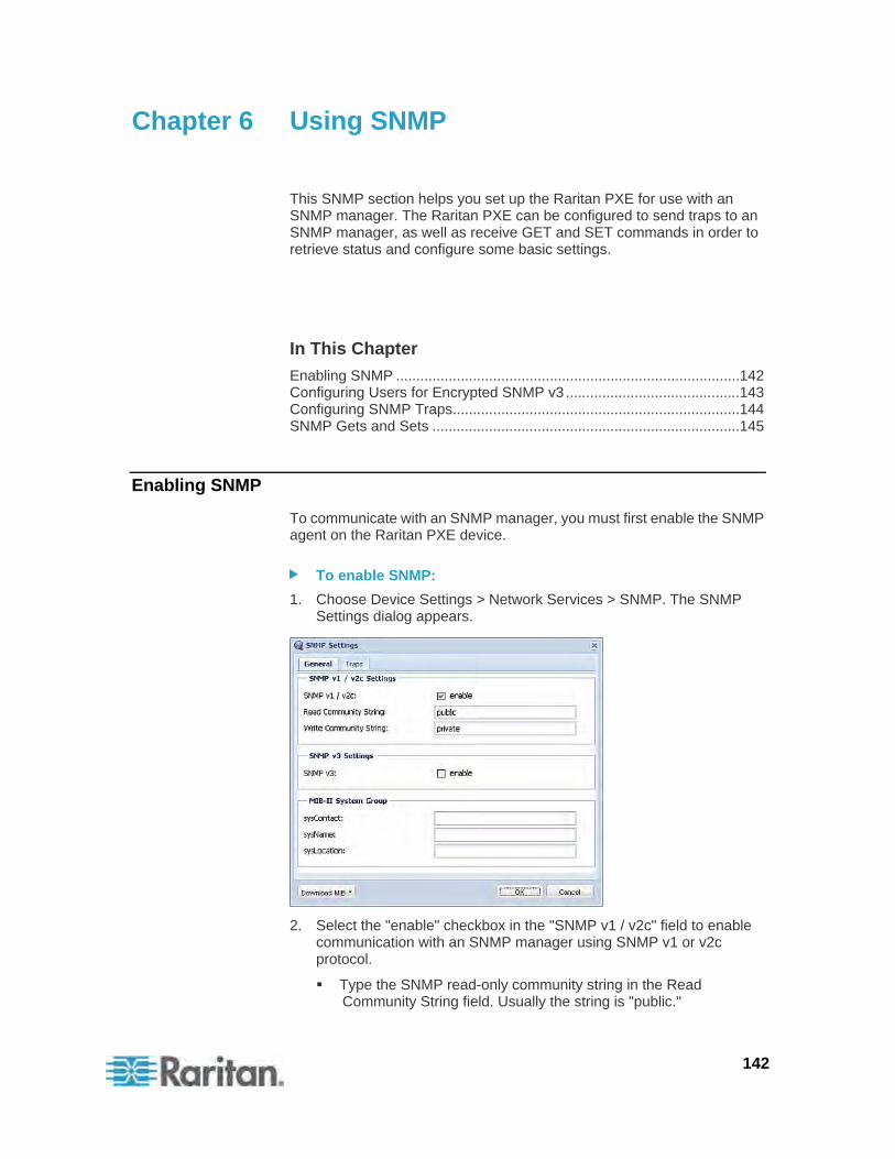
142
This SNMP section helps you set up the Raritan PXE for use with an SNMP manager. The Raritan PXE can be configured to send traps to an SNMP manager, as well as receive GET and SET commands in order to retrieve status and configure some basic settings.
In This Chapter
Enabling SNMP .....................................................................................142 Configuring Users for Encrypted SNMP v3 ...........................................143 Configuring SNMP Traps.......................................................................144 SNMP Gets and Sets ............................................................................145
Enabling SNMP
To communicate with an SNMP manager, you must first enable the SNMP agent on the Raritan PXE device.
To enable SNMP:
1. Choose Device Settings > Network Services > SNMP. The SNMP Settings dialog appears.
2. Select the "enable" checkbox in the "SNMP v1 / v2c" field to enable communication with an SNMP manager using SNMP v1 or v2c protocol.
Type the SNMP read-only community string in the Read Community String field. Usually the string is "public."
Chapter 6 Using SNMP
Chapter 6: Using SNMP
143
Type the read/write community string in the Write Community String field. Usually the string is "private."
3. Select the "enable" checkbox in the "SNMP v3" field to enable communication with an SNMP manager using SNMP v3 protocol.
Tip: You can permit or disallow a user to access the Raritan PXE via the SNMP v3 protocol. See Configuring Users for Encrypted SNMP v3 (on page 143).
4. Type the SNMP MIB-II sysContact value in the sysContact field.
5. Type the SNMP MIB-II sysName value in the sysName field.
6. Type the SNMP MIB-II sysLocation value in the sysLocation field.
7. Click OK to save the changes.
Important: You must download the SNMP MIB for your Raritan PXE to use with your SNMP manager. Click Download MIB in this dialog to download the desired MIB file. For more details, see Downloading SNMP MIB (on page 145).
Configuring Users for Encrypted SNMP v3
The SNMP v3 protocol allows for encrypted communication. To take advantage of this, users need to have an Authentication Pass Phrase and Privacy Pass Phrase, which act as shared secrets between them and the Raritan PXE.
To configure users for SNMP v3 encrypted communication:
1. Choose User Management > Users. The Manage Users dialog appears.
2. Select the user by clicking it.
3. Click Edit or double-click the user. The Edit User 'XXX' dialog appears, where XXX is the user name.
4. To change the SNMPv3 access permissions, click the SNMPv3 tab and make necessary changes. For details, see Step 6 of Creating a User Profile (on page 68).
5. Click OK to save the changes. The user is now set up for encrypted SNMP v3 communication.
Chapter 6: Using SNMP
144
Configuring SNMP Traps
The Raritan PXE automatically keeps an internal log of events that occur. See Configuring Event Rules (on page 105). These events can also be used to send SNMP traps to a third party manager.
To configure the Raritan PXE to send SNMP traps:
1. Choose Device Settings > Event Rules. The Event Rule Settings dialog appears.
2. On the Rules tab, select the System SNMP Trap Rule.
3. Select the Enabled checkbox to enable this event rule.
4. Click Save to save the changes.
5. Click the Actions tab if you have not configured the SNMP trap actions.
6. Select System SNMP Trap Action to set up the trap destinations.
7. Type an IP address in the Host 1 field. This is the address to which traps are sent by the SNMP system agent.
8. Type the communication port number in the Port 1 field.
9. Type the name of the SNMP community in the Community field. The community is the group representing the Raritan PXE and all SNMP management stations.
10. To specify more than one SNMP trap destination, repeat Steps 8 to 10 for additional destinations. A maximum of 3 destinations can be specified.
11. Click Save to save the changes.
12. Click Close to quit the dialog.
Note: You should update the MIB used by your SNMP manager when updating to a new Raritan PXE release. This ensures your SNMP manager has the correct MIB for the release you are using. See Downloading SNMP MIB (on page 145).
Chapter 6: Using SNMP
145
SNMP Gets and Sets
In addition to sending traps, the Raritan PXE is able to receive SNMP get and set requests from third-party SNMP managers.
Get requests are used to retrieve information about the Raritan PXE, such as the system location, and the current on a specific outlet.
Set requests are used to configure a subset of the information, such as the SNMP system name.
Note: The SNMP system name is the Raritan PXE device name. When you change the SNMP system name, the device name shown in the web interface is also changed.
The Raritan PXE does NOT support configuring IPv6-related parameters using the SNMP set requests.
Valid objects for these requests are limited to those found in the SNMP MIB-II System Group and the custom Raritan PXE MIB.
The Raritan PXE MIB
The SNMP MIB file is required for using your Raritan PXE device with an SNMP manager. An SNMP MIB file describes the SNMP functions.
Downloading SNMP MIB
The SNMP MIB file for the Raritan PXE can be easily downloaded from the web interface. There are two ways to download the SNMP MIB file.
To download the file from the SNMP Settings dialog:
1. Choose Device Settings > Network Services > SNMP. The SNMP Settings dialog appears.
2. Click Download MIB. A submenu of MIB files appear.
3. Select the desired MIB file to download.
PDU-MIB: The SNMP MIB file for Raritan PXE's power management.
ASSETMANAGEMENT-MIB: The SNMP MIB file for asset management.
Note: The Raritan PXE device does not support the asset management feature so you can ignore the Asset Management-related function.
4. Click Save to save the file onto your computer.
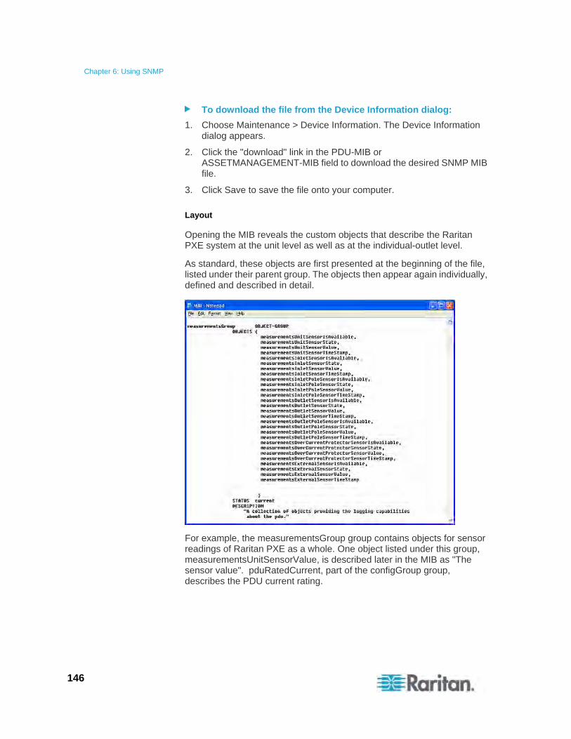
Chapter 6: Using SNMP
146
To download the file from the Device Information dialog:
1. Choose Maintenance > Device Information. The Device Information dialog appears.
2. Click the "download" link in the PDU-MIB or ASSETMANAGEMENT-MIB field to download the desired SNMP MIB file.
3. Click Save to save the file onto your computer.
Layout
Opening the MIB reveals the custom objects that describe the Raritan PXE system at the unit level as well as at the individual-outlet level.
As standard, these objects are first presented at the beginning of the file, listed under their parent group. The objects then appear again individually, defined and described in detail.
For example, the measurementsGroup group contains objects for sensor readings of Raritan PXE as a whole. One object listed under this group, measurementsUnitSensorValue, is described later in the MIB as "The sensor value". pduRatedCurrent, part of the configGroup group, describes the PDU current rating.

Chapter 6: Using SNMP
147
SNMP Sets and Thresholds
Some objects can be configured from the SNMP manager using SNMP set commands. Objects that can be configured have a MAX-ACCESS level of "read-write" in the MIB.
These objects include threshold objects, which causes the Raritan PXE to generate a warning and send an SNMP trap when certain parameters are exceeded. See Setting Power Thresholds (on page 102) for a description of how thresholds work.
Note: When configuring the thresholds via SNMP set commands, ensure the value of upper critical threshold is higher than that of upper warning threshold.
A Note about Enabling Thresholds
When enabling previously disabled thresholds via SNMP, make sure you set a correct value for all thresholds that are supposed to be enabled prior to actually enabling them. Otherwise, you may get an error message.
148
This section explains how to use the command line interface (CLI) to administer a Raritan PXE device.
In This Chapter
About the Interface ................................................................................148 Logging in to CLI ...................................................................................148 Help Command......................................................................................151 Showing Information..............................................................................152 Configuring the Raritan PXE Device and Network................................165 Unblocking a User .................................................................................250 Resetting the Raritan PXE.....................................................................251 Network Troubleshooting.......................................................................251 Querying Available Parameters for a Command...................................255 Retrieving Previous Commands............................................................255 Automatically Completing a Command .................................................256 Logging out of CLI .................................................................................256
About the Interface
The Raritan PXE provides a command line interface that enables data center administrators to perform some basic management tasks.
Using this interface, you can do the following:
Reset the Raritan PXE device
Display the Raritan PXE and network information, such as the device name, firmware version, IP address, and so on
Configure the Raritan PXE and network settings
Troubleshoot network problems
You can access the interface over a serial connection using a terminal emulation program such as HyperTerminal, or via a Telnet or SSH client such as PuTTY.
Note: Telnet access is disabled by default because it communicates openly and is thus insecure. To enable Telnet, see Modifying the Network Service Settings (on page 58).
Logging in to CLI
Logging in via HyperTerminal over a local connection is a little different than logging in using SSH or Telnet.
Chapter 7 Using the Command Line Interface

Chapter 7: Using the Command Line Interface
149
With HyperTerminal
You can use any terminal emulation programs for local access to the command line interface.
This section illustrates HyperTerminal, which is part of Windows operating systems prior to Windows Vista.
To log in using HyperTerminal:
1. Connect your computer to the Raritan PXE device via a local connection.
2. Launch HyperTerminal on your computer and open a console window. When the window first opens, it is blank.
Make sure the COM port settings use this configuration:
Bits per second = 115200 (115.2Kbps)
Data bits = 8
Stop bits = 1
Parity = None
Flow control = None
Tip: For a USB connection, you can find out which COM port is assigned to the Raritan PXE by choosing Control Panel > System > Hardware > Device Manager, and locating the "Dominion Serial Console" under the Ports group.
3. Press Enter. The Username prompt appears.
4. Type a name and press Enter. The name is case sensitive, so make sure you capitalize the correct letters. Then you are prompted to enter a password.
5. Type a password and press Enter. The password is case sensitive, so make sure you capitalize the correct letters.
After properly entering the password, the # or > system prompt appears. See Different CLI Modes and Prompts (on page 151) for details.
Tip: The "Last Login" information, including the date and time, is also displayed if the same user profile was once used to log in to the Raritan PXE web interface or CLI.
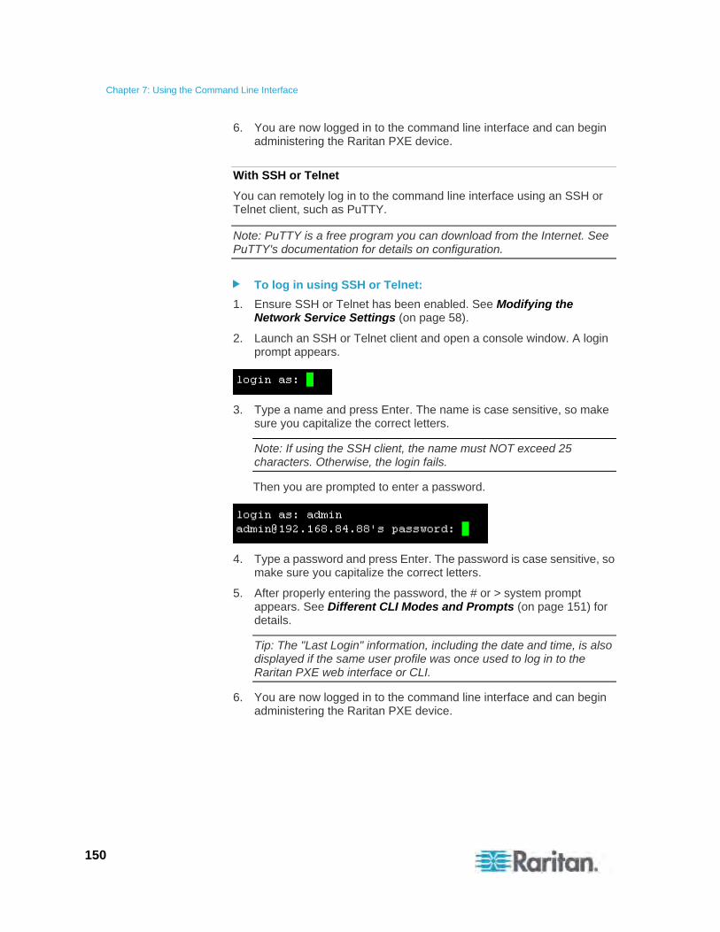
Chapter 7: Using the Command Line Interface
150
6. You are now logged in to the command line interface and can begin administering the Raritan PXE device.
With SSH or Telnet
You can remotely log in to the command line interface using an SSH or Telnet client, such as PuTTY.
Note: PuTTY is a free program you can download from the Internet. See PuTTY's documentation for details on configuration.
To log in using SSH or Telnet:
1. Ensure SSH or Telnet has been enabled. See Modifying the Network Service Settings (on page 58).
2. Launch an SSH or Telnet client and open a console window. A login prompt appears.
3. Type a name and press Enter. The name is case sensitive, so make sure you capitalize the correct letters.
Note: If using the SSH client, the name must NOT exceed 25 characters. Otherwise, the login fails.
Then you are prompted to enter a password.
4. Type a password and press Enter. The password is case sensitive, so make sure you capitalize the correct letters.
5. After properly entering the password, the # or > system prompt appears. See Different CLI Modes and Prompts (on page 151) for details.
Tip: The "Last Login" information, including the date and time, is also displayed if the same user profile was once used to log in to the Raritan PXE web interface or CLI.
6. You are now logged in to the command line interface and can begin administering the Raritan PXE device.
Chapter 7: Using the Command Line Interface
151
Different CLI Modes and Prompts
Depending on the login name you use and the mode you enter, the system prompt in the CLI varies.
User Mode: When you log in as a normal user, who does not have full permissions to configure the Raritan PXE device, the > prompt appears.
Administrator Mode: When you log in as an administrator, who has full permissions to configure the Raritan PXE device, the # prompt appears.
Configuration Mode: You can enter the configuration mode from the administrator mode. In this mode, the prompt changes to config:# and you can change Raritan PXE device and network configurations. See Entering the Configuration Mode (on page 165).
Diagnostic Mode: You can enter the diagnostic mode from the administrator mode. In this mode, the prompt changes to diag:> and you can perform the network troubleshooting commands, such as the ping command. See Entering the Diagnostic Mode (on page 252).
Closing a Serial Connection
Close the window or terminal emulation program when you finish accessing a Raritan PXE device over the serial connection.
When accessing or upgrading multiple Raritan PXE devices, do not transfer the serial cable from one device to another without closing the serial connection window first.
Help Command
The help command shows a list of main CLI commands. This is helpful when you are not familiar with the commands.
The help command syntax is:
# help
Press Enter after typing the command, and a list of main commands is displayed.
Tip: You can check what parameters are available for a specific CLI command by adding a question mark to the end of the command. See Querying Available Parameters for a Command (on page 255).
Chapter 7: Using the Command Line Interface
152
Showing Information
You can use the show commands to view current settings or status of the Raritan PXE device or part of it, such as the IP address, networking mode, firmware version, circuit breaker state, inlet ratings, and so on.
Some "show" commands have two formats: one with the parameter "details" and the other without. The difference is that the command without the parameter "details" displays a shortened version of information while the other displays in-depth information.
After typing a "show" command, press Enter to execute it.
Note: Depending on your login name, the # prompt may be replaced by the > prompt.
Network Configuration
This command shows the network configuration, such as the IP address, networking mode, and MAC address.
# show network
IP Configuration
This command shows the IP-related configuration, such as IPv4 and IPv6 configuration, address(es), gateway, and subnet mask.
# show network ip <option>
Variables:
<option> is one of the options: all, v4 or v6.
Option Description
all This options shows both of IPv4 and IPv6 settings.
Tip: You can also type the command without adding this option "all" to get the same data.
v4 This option shows the IPv4 settings only.
v6 This option shows the IPv6 settings only.

Chapter 7: Using the Command Line Interface
153
LAN Interface Settings
This command shows the LAN interface information, such as LAN interface speed, duplex mode, and current LAN interface status.
# show network interface
Networking Mode
This command shows whether the current networking mode is wired or wireless.
# show network mode
Note that the Raritan PXE device does NOT support the wireless networking mode so the network mode always shows "wired."
Network Service Settings
This command shows the network service settings, including the Telnet setting, TCP ports for HTTP, HTTPS and SSH services, and SNMP settings.
# show network services <option>
Variables:
<option> is one of the options: all, http, https, telnet, ssh and snmp.
Option Description
all Displays the settings of all network services, including HTTP, HTTPS, Telnet, SSH and SNMP.
Tip: You can also type the command without adding this option "all" to get the same data.
http Only displays the TCP port for the HTTP service.
https Only displays the TCP port for the HTTPS service.
telnet Only displays the settings of the Telnet service.
ssh Only displays the settings of the SSH service.
snmp Only displays the SNMP settings.
Chapter 7: Using the Command Line Interface
154
PDU Configuration
This command shows the PDU configuration, such as the device name, firmware version and model type.
# show pdu
To show detailed information, add the parameter "details" to the end of the command.
# show pdu details
Outlet Information
This command syntax shows the outlet information.
# show outlets <n>
To show detailed information, add the parameter "details" to the end of the command.
# show outlets <n> details
Variables:
<n> is one of the options: all, or a number.
Option Description
all Displays the information for all outlets.
Tip: You can also type the command without adding this option "all" to get the same data.
A specific outlet number
Displays the information for the specified outlet only.
Displayed information:
Without the parameter "details," only the outlet name is displayed.
With the parameter "details," more outlet information is displayed in addition to the outlet name, such as the outlet rating.
Chapter 7: Using the Command Line Interface
155
Inlet Information
This command syntax shows the inlet information.
# show inlets <n>
To show detailed information, add the parameter "details" to the end of the command.
# show inlets <n> details
Variables:
<n> is one of the options: all, or a number.
Option Description
all Displays the information for all inlets.
Tip: You can also type the command without adding this option "all" to get the same data.
A specific inlet number
Displays the information for the specified inlet only.
An inlet number may need to be specified only when there are more than 1 inlet on your PDU.
Displayed information:
Without the parameter "details," only the inlet's RMS current value(s) and inlet name are displayed.
With the parameter "details," more inlet information is displayed in addition to the RMS current values, such as the inlet's RMS current, voltage, and active power.
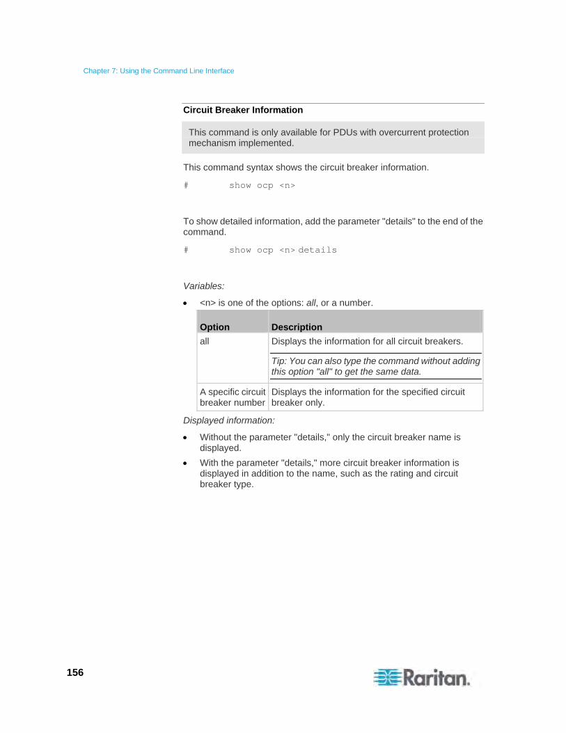
Chapter 7: Using the Command Line Interface
156
Circuit Breaker Information
This command is only available for PDUs with overcurrent protection mechanism implemented.
This command syntax shows the circuit breaker information.
# show ocp <n>
To show detailed information, add the parameter "details" to the end of the command.
# show ocp <n> details
Variables:
<n> is one of the options: all, or a number.
Option Description
all Displays the information for all circuit breakers.
Tip: You can also type the command without adding this option "all" to get the same data.
A specific circuit breaker number
Displays the information for the specified circuit breaker only.
Displayed information:
Without the parameter "details," only the circuit breaker name is displayed.
With the parameter "details," more circuit breaker information is displayed in addition to the name, such as the rating and circuit breaker type.
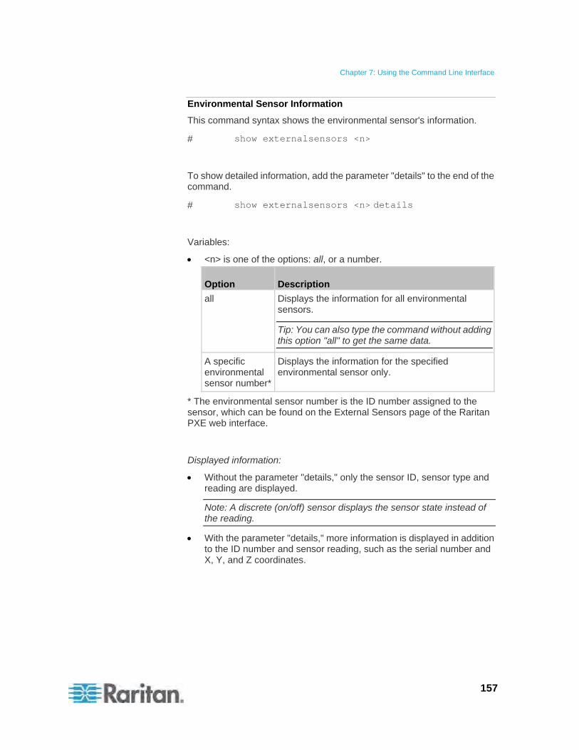
Chapter 7: Using the Command Line Interface
157
Environmental Sensor Information
This command syntax shows the environmental sensor's information.
# show externalsensors <n>
To show detailed information, add the parameter "details" to the end of the command.
# show externalsensors <n> details
Variables:
<n> is one of the options: all, or a number.
Option Description
all Displays the information for all environmental sensors.
Tip: You can also type the command without adding this option "all" to get the same data.
A specific environmental sensor number*
Displays the information for the specified environmental sensor only.
* The environmental sensor number is the ID number assigned to the sensor, which can be found on the External Sensors page of the Raritan PXE web interface.
Displayed information:
Without the parameter "details," only the sensor ID, sensor type and reading are displayed.
Note: A discrete (on/off) sensor displays the sensor state instead of the reading.
With the parameter "details," more information is displayed in addition to the ID number and sensor reading, such as the serial number and X, Y, and Z coordinates.
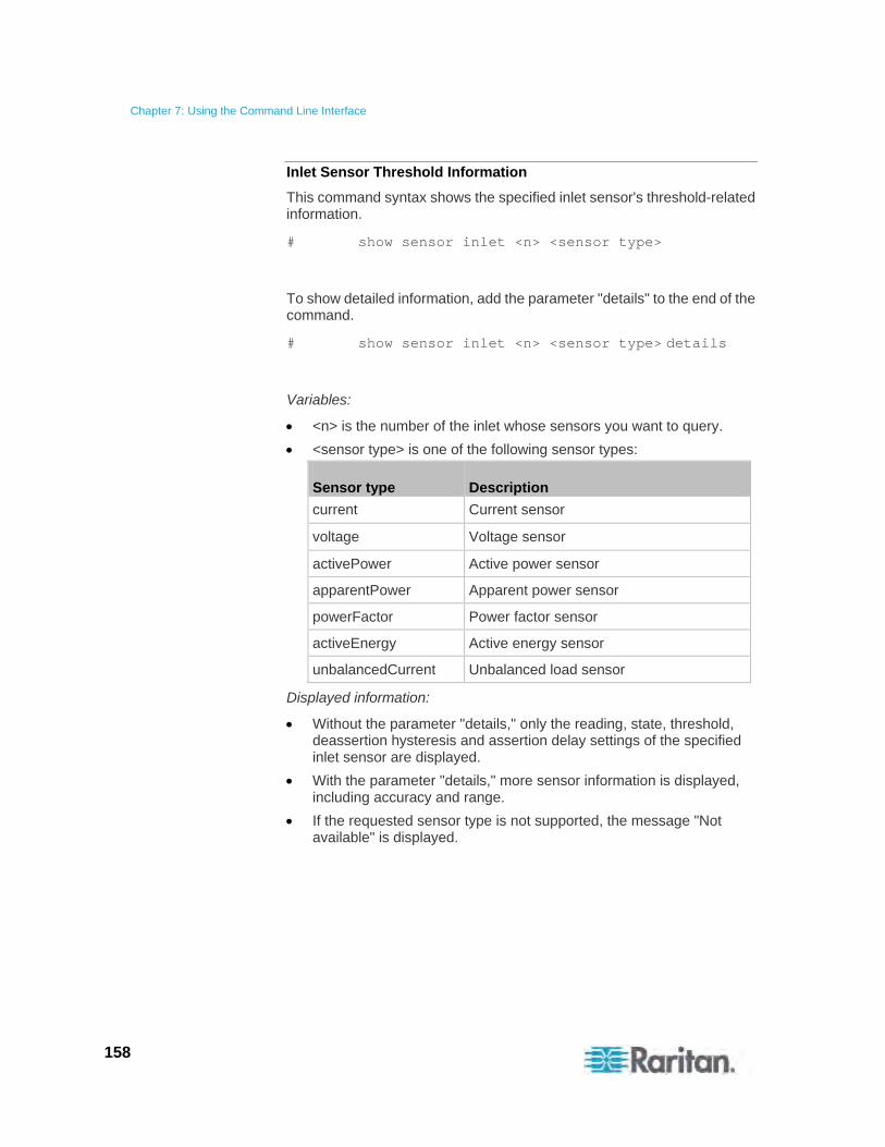
Chapter 7: Using the Command Line Interface
158
Inlet Sensor Threshold Information
This command syntax shows the specified inlet sensor's threshold-related information.
# show sensor inlet <n> <sensor type>
To show detailed information, add the parameter "details" to the end of the command.
# show sensor inlet <n> <sensor type> details
Variables:
<n> is the number of the inlet whose sensors you want to query.
<sensor type> is one of the following sensor types:
Sensor type Description
current Current sensor
voltage Voltage sensor
activePower Active power sensor
apparentPower Apparent power sensor
powerFactor Power factor sensor
activeEnergy Active energy sensor
unbalancedCurrent Unbalanced load sensor
Displayed information:
Without the parameter "details," only the reading, state, threshold, deassertion hysteresis and assertion delay settings of the specified inlet sensor are displayed.
With the parameter "details," more sensor information is displayed, including accuracy and range.
If the requested sensor type is not supported, the message "Not available" is displayed.
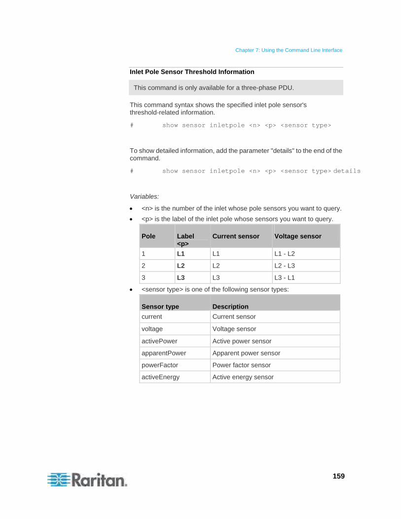
Chapter 7: Using the Command Line Interface
159
Inlet Pole Sensor Threshold Information
This command is only available for a three-phase PDU.
This command syntax shows the specified inlet pole sensor's threshold-related information.
# show sensor inletpole <n> <p> <sensor type>
To show detailed information, add the parameter "details" to the end of the command.
# show sensor inletpole <n> <p> <sensor type> details
Variables:
<n> is the number of the inlet whose pole sensors you want to query.
<p> is the label of the inlet pole whose sensors you want to query.
Pole Label <p>
Current sensor Voltage sensor
1 L1 L1 L1 - L2
2 L2 L2 L2 - L3
3 L3 L3 L3 - L1
<sensor type> is one of the following sensor types:
Sensor type Description
current Current sensor
voltage Voltage sensor
activePower Active power sensor
apparentPower Apparent power sensor
powerFactor Power factor sensor
activeEnergy Active energy sensor

Chapter 7: Using the Command Line Interface
160
Displayed information:
Without the parameter "details," only the reading, state, threshold, deassertion hysteresis and assertion timeout settings of the specified inlet pole sensor are displayed.
With the parameter "details," more sensor information is displayed, including accuracy and range.
If the requested sensor type is not supported, the message "Not available" is displayed.
Environmental Sensor Threshold Information
This command syntax shows the specified environmental sensor's threshold-related information.
# show sensor externalsensor <n>
To show detailed information, add the parameter "details" to the end of the command.
# show sensor externalsensor <n> details
Variables:
<n> is the environmental sensor number. The environmental sensor number is the ID number assigned to the sensor, which can be found on the External Sensors page of the Raritan PXE web interface.
Displayed information:
Without the parameter "details," only the reading, threshold, deassertion hysteresis and assertion timeout settings of the specified environmental sensor are displayed.
With the parameter "details," more sensor information is displayed, including accuracy and range.
Note: For a discrete (on/off) sensor, the threshold-related and accuracy-related data is NOT available.
Chapter 7: Using the Command Line Interface
161
Security Settings
This command shows the security settings of the Raritan PXE device.
# show security
To show detailed information, add the parameter "details" to the end of the command.
# show security details
Displayed information:
Without the parameter "details," the information including IP access control, role-based access control, password policy, and HTTPS encryption is displayed.
With the parameter "details," more security information is displayed, such as user blocking time and user idle timeout.
Existing User Profiles
This command shows the data of one or all existing user profiles.
# show user <user_name>
To show detailed information, add the parameter "details" to the end of the command.
# show user <user_name> details
Variables:
<user_name> is the name of the user whose profile you want to query. The variable can be one of the options: all or a user's name.
Option Description
all This option shows all existing user profiles.
Tip: You can also type the command without adding this option "all" to get the same data.
a specific user's name This option shows the profile of the specified user only.
Displayed information:
Chapter 7: Using the Command Line Interface
162
Without the parameter "details," only four pieces of user information are displayed: user name, "enabled" status, SNMP v3 access privilege, and role(s).
With the parameter "details," more user information is displayed, such as the telephone number, e-mail address, preferred temperature unit and so on.
Existing Roles
This command shows the data of one or all existing roles.
# show roles <role_name>
Variables:
<role_name> is the name of the role whose permissions you want to query. The variable can be one of the following options:
Option Description
all This option shows all existing roles.
Tip: You can also type the command without adding this option "all" to get the same data.
a specific role's name This option shows the data of the specified role only.
Displayed information:
Role settings are displayed, including the role description and privileges.
EnergyWise Settings
This command shows the Raritan PXE device's current configuration for Cisco® EnergyWise.
# show energywise
Reliability Data
This command shows the reliability data.
# show reliability data
Chapter 7: Using the Command Line Interface
163
Reliability Error Log
This command shows the reliability error log.
# show reliability errorlog <n>
Variables:
<n> is one of the options: all, or a number.
Option Description
all Displays all entries in the reliability error log.
Tip: You can also type the command without adding this option "all" to get the same data.
A specific number
Displays the specified number of last entries in the reliability error log.
Command History
This command syntax shows the command history for current connection session.
# show history
Displayed information:
A list of commands that were previously entered in the current session is displayed.
History Buffer Length
This command syntax shows the length of the history buffer for storing the history commands.
# show history bufferlength
Displayed information:
The current history buffer length is displayed.
Examples
This section provides examples of the show command.
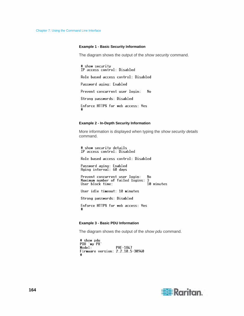
Chapter 7: Using the Command Line Interface
164
Example 1 - Basic Security Information
The diagram shows the output of the show security command.
Example 2 - In-Depth Security Information
More information is displayed when typing the show security details command.
Example 3 - Basic PDU Information
The diagram shows the output of the show pdu command.
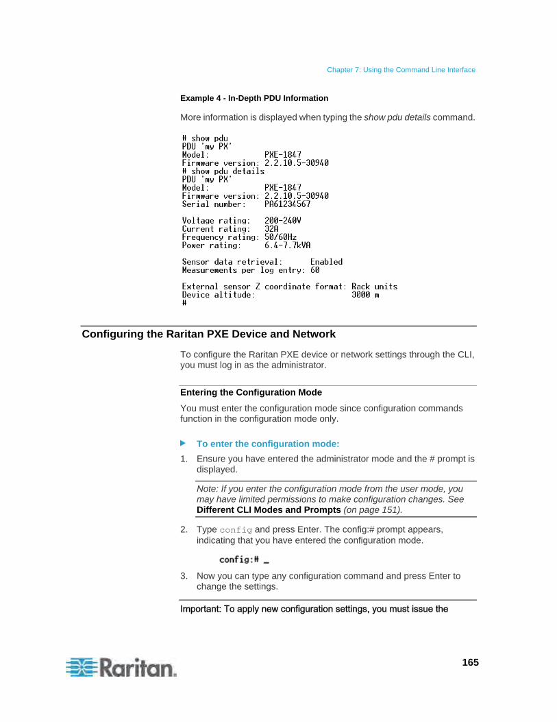
Chapter 7: Using the Command Line Interface
165
Example 4 - In-Depth PDU Information
More information is displayed when typing the show pdu details command.
Configuring the Raritan PXE Device and Network
To configure the Raritan PXE device or network settings through the CLI, you must log in as the administrator.
Entering the Configuration Mode
You must enter the configuration mode since configuration commands function in the configuration mode only.
To enter the configuration mode:
1. Ensure you have entered the administrator mode and the # prompt is displayed.
Note: If you enter the configuration mode from the user mode, you may have limited permissions to make configuration changes. See Different CLI Modes and Prompts (on page 151).
2. Type config and press Enter. The config:# prompt appears, indicating that you have entered the configuration mode.
3. Now you can type any configuration command and press Enter to change the settings.
Important: To apply new configuration settings, you must issue the
Chapter 7: Using the Command Line Interface
166
"apply" command before closing the terminal emulation program. Closing the program does not save any configuration changes. See Quitting the Configuration Mode (on page 250).
PDU Configuration Commands
A PDU configuration command begins with pdu. You can use the PDU configuration commands to change the settings that apply to the whole Raritan PXE device.
The commands are case sensitive so ensure you capitalize them correctly.
Changing the PDU Name
This command syntax changes the Raritan PXE device's name.
config:# pdu name "<name>"
Variables:
<name> is a string comprising up to 32 ASCII printable characters. The <name> variable must be enclosed in quotes when it contains spaces.
Example
The following command assigns the name "my px12" to the PDU.
config:# pdu name "my px12"
Enabling or Disabling Data Logging
This command syntax enables or disables the data logging feature.
config:# pdu dataRetrieval <option>
Variables:
<option> is one of the options: enable or disable.
Option Description
enable Enables the data logging feature.
disable Disables the data logging feature.
Chapter 7: Using the Command Line Interface
167
For more information, see Setting Data Logging (on page 65).
Example
The following command enables the data logging feature.
config:# pdu dataRetrieval enable
Setting the Data Logging Measurements Per Entry
This command syntax defines the number of measurements accumulated per log entry.
config:# pdu measurementsPerLogEntry <number>
Variables:
<number> is an integer between 1 and 600. The default is 60 samples per log entry.
For more information, see Setting Data Logging (on page 65).
Example
The following command determines that 66 measurements are accumulated per log entry for sensors, that is, 66 seconds.
config:# pdu measurementsPerLogEntry 66
Specifying the Device Altitude
This command syntax specifies your Raritan PXE device's altitude above sea level (in meters). You must specify the Raritan PXE device's altitude above sea level if a Raritan differential air pressure sensor is attached. This is because the device's altitude is associated with the altitude correction factor. See Altitude Correction Factors (on page 275).
config:# pdu deviceAltitude <altitude>
Variables:
<altitude> is an integer between 1 and 3000 meters.
Chapter 7: Using the Command Line Interface
168
Example
The following command determines that the Raritan PXE device is located at 1500 meters above sea level.
config:# pdu deviceAltitude 1500
Setting the Z Coordinate Format for Environmental Sensors
This command syntax enables or disables the use of rack units for specifying the height (Z coordinate) of environmental sensors.
config:# pdu externalSensorsZCoordinateFormat <option>
Variables:
<option> is one of the options: rackUnits or freeForm.
Option Description
rackUnits The height of the Z coordinate is measured in standard rack units. When this is selected, you can type a numeric value in the rack unit to describe the Z coordinate of any environmental sensors.
freeForm Any alphanumeric string can be used for specifying the Z coordinate.
Note: After determining the format for the Z coordinate, you can set a value for it. See Setting the Z Coordinate (on page 210).
Example
The following command determines that the unit of rack is used for specifying the Z coordinate of environmental sensors.
config:# pdu externalSensorsZCoordinateFormat rackUnits
Networking Configuration Commands
A number of network settings can be changed through the CLI, such as the IP address, transmission speed, duplex mode, and so on.
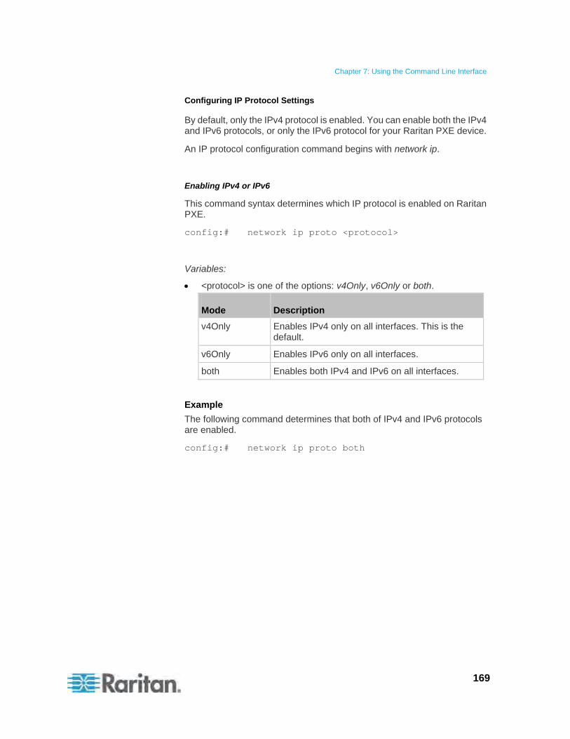
Chapter 7: Using the Command Line Interface
169
Configuring IP Protocol Settings
By default, only the IPv4 protocol is enabled. You can enable both the IPv4 and IPv6 protocols, or only the IPv6 protocol for your Raritan PXE device.
An IP protocol configuration command begins with network ip.
Enabling IPv4 or IPv6
This command syntax determines which IP protocol is enabled on Raritan PXE.
config:# network ip proto <protocol>
Variables:
<protocol> is one of the options: v4Only, v6Only or both.
Mode Description
v4Only Enables IPv4 only on all interfaces. This is the default.
v6Only Enables IPv6 only on all interfaces.
both Enables both IPv4 and IPv6 on all interfaces.
Example
The following command determines that both of IPv4 and IPv6 protocols are enabled.
config:# network ip proto both
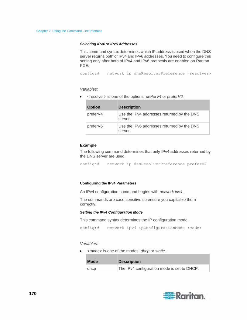
Chapter 7: Using the Command Line Interface
170
Selecting IPv4 or IPv6 Addresses
This command syntax determines which IP address is used when the DNS server returns both of IPv4 and IPv6 addresses. You need to configure this setting only after both of IPv4 and IPv6 protocols are enabled on Raritan PXE.
config:# network ip dnsResolverPreference <resolver>
Variables:
<resolver> is one of the options: preferV4 or preferV6.
Option Description
preferV4 Use the IPv4 addresses returned by the DNS server.
preferV6 Use the IPv6 addresses returned by the DNS server.
Example
The following command determines that only IPv4 addresses returned by the DNS server are used.
config:# network ip dnsResolverPreference preferV4
Configuring the IPv4 Parameters
An IPv4 configuration command begins with network ipv4.
The commands are case sensitive so ensure you capitalize them correctly.
Setting the IPv4 Configuration Mode
This command syntax determines the IP configuration mode.
config:# network ipv4 ipConfigurationMode <mode>
Variables:
<mode> is one of the modes: dhcp or static.
Mode Description
dhcp The IPv4 configuration mode is set to DHCP.
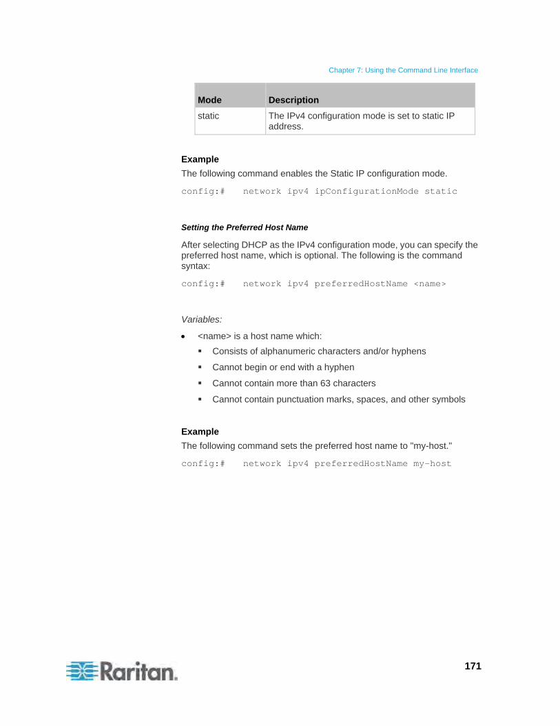
Chapter 7: Using the Command Line Interface
171
Mode Description
static The IPv4 configuration mode is set to static IP address.
Example
The following command enables the Static IP configuration mode.
config:# network ipv4 ipConfigurationMode static
Setting the Preferred Host Name
After selecting DHCP as the IPv4 configuration mode, you can specify the preferred host name, which is optional. The following is the command syntax:
config:# network ipv4 preferredHostName <name>
Variables:
<name> is a host name which:
Consists of alphanumeric characters and/or hyphens
Cannot begin or end with a hyphen
Cannot contain more than 63 characters
Cannot contain punctuation marks, spaces, and other symbols
Example
The following command sets the preferred host name to "my-host."
config:# network ipv4 preferredHostName my-host

Chapter 7: Using the Command Line Interface
172
Setting the IPv4 Address
After selecting the static IP configuration mode, you can use this command syntax to assign a permanent IP address to the Raritan PXE device.
config:# network ipv4 ipAddress <ip address>
Variables:
<ip address> is the IP address being assigned to your Raritan PXE device. The value ranges from 0.0.0.0 to 255.255.255.255.
Example
The following command assigns the static IPv4 address "192.168.84.222" to the Raritan PXE device.
config:# network ipv4 ipAddress 192.168.84.222
Setting the IPv4 Subnet Mask
After selecting the static IP configuration mode, you can use this command syntax to define the subnet mask.
config:# network ipv4 subnetMask <netmask>
Variables:
<netmask> is the subnet mask address. The value ranges from 0.0.0.0 to 255.255.255.255.
Example
The following command sets the subnet mask to 192.168.84.0.
config:# network ipv4 subnetMask 192.168.84.0
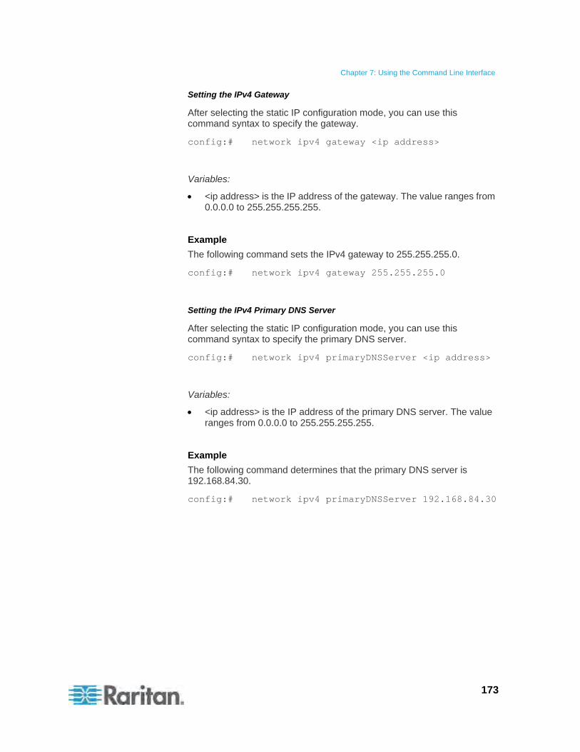
Chapter 7: Using the Command Line Interface
173
Setting the IPv4 Gateway
After selecting the static IP configuration mode, you can use this command syntax to specify the gateway.
config:# network ipv4 gateway <ip address>
Variables:
<ip address> is the IP address of the gateway. The value ranges from 0.0.0.0 to 255.255.255.255.
Example
The following command sets the IPv4 gateway to 255.255.255.0.
config:# network ipv4 gateway 255.255.255.0
Setting the IPv4 Primary DNS Server
After selecting the static IP configuration mode, you can use this command syntax to specify the primary DNS server.
config:# network ipv4 primaryDNSServer <ip address>
Variables:
<ip address> is the IP address of the primary DNS server. The value ranges from 0.0.0.0 to 255.255.255.255.
Example
The following command determines that the primary DNS server is 192.168.84.30.
config:# network ipv4 primaryDNSServer 192.168.84.30

Chapter 7: Using the Command Line Interface
174
Setting the IPv4 Secondary DNS Server
After selecting the static IP configuration mode, you can use this command syntax to specify the secondary DNS server.
config:# network ipv4 secondaryDNSServer <ip address>
Variables:
<ip address> is the IP address of the secondary DNS server. The value ranges from 0.0.0.0 to 255.255.255.255.
Note: The Raritan PXE supports a maximum of 3 DNS servers. If two IPv4 DNS servers and two IPv6 DNS servers are available, the Raritan PXE only uses the primary IPv4 and IPv6 DNS servers.
Example
The following command determines that the secondary DNS server is 192.168.84.33.
config:# network ipv4 secondaryDNSServer 192.168.84.33
Overriding the IPv4 DHCP-Assigned DNS Server
After specifying the primary/secondary DNS server, you can use this command to override the DHCP-assigned DNS server with the one you specified.
config:# network ipv4 overrideDNS <option>
Variables:
<option> is one of the options: enable or disable.
Option Description
enable This option overrides the DHCP-assigned DNS server with the primary/secondary DNS server you assign.
disable This option resumes using the DHCP-assigned DNS server.
Chapter 7: Using the Command Line Interface
175
Example
The following command overrides the DHCP-assigned DNS server with the one you specified.
config:# network ipv4 overrideDNS enable
Configuring the IPv6 Parameters
An IPv6 configuration command begins with network ipv6.
The commands are case sensitive so ensure you capitalize them correctly.
Setting the IPv6 Configuration Mode
This command syntax determines the IP configuration mode.
config:# network ipv6 ipConfigurationMode <mode>
Variables:
<mode> is one of the modes: automatic or static.
Mode Description
automatic The IPv6 configuration mode is set to automatic.
static The IPv6 configuration mode is set to static IP address.
Example
The following command sets the IP configuration mode to the static IP address mode.
config:# network ipv6 ipConfigurationMode static
Chapter 7: Using the Command Line Interface
176
Setting the IPv6 Address
After selecting the static IP configuration mode, you can use this command syntax to assign a permanent IP address to the Raritan PXE device.
config:# network ipv6 ipAddress <ip address>
Variables:
<ip address> is the IP address being assigned to your Raritan PXE device. This value uses the IPv6 address format.
Example
The following command assigns the static IPv6 address "3210:4179:0:8:0:800:200C:417A" to the Raritan PXE device.
config:# network ipv6 ipAddress 3210:4179:0:8:0:800:200C:417A
Setting the IPv6 Gateway
After selecting the static IP configuration mode, you can use this command syntax to specify the gateway.
config:# network ipv6 gateway <ip address>
Variables:
<ip address> is the IP address of the gateway. This value uses the IPv6 address format.
Example
The following command sets the gateway to 500:0:330:0:4:9:3:2.
config:# network ipv6 gateway 500:0:330:0:4:9:3:2
Chapter 7: Using the Command Line Interface
177
Setting the IPv6 Primary DNS Server
After selecting the static IP configuration mode, you can use this command syntax to specify the primary DNS server. It is required to enable overriding the auto-assigned DNS server before you can specify the DNS servers manually. See Overriding the IPv6 DHCP-Assigned DNS Server (on page 178).
config:# network ipv6 primaryDNSServer <ip address>
Variables:
<ip address> is the IP address of the primary DNS server. This value uses the IPv6 address format.
Example
The following command determines that the primary DNS server is 2103:288:8201:1::14.
config:# network ipv6 primaryDNSServer 2103:288:8201:1::14
Setting the IPv6 Secondary DNS Server
After selecting the static IP configuration mode, you can use this command syntax to specify the secondary DNS server. It is required to enable overriding the auto-assigned DNS server before you can specify the DNS servers manually. See Overriding the IPv6 DHCP-Assigned DNS Server (on page 178).
config:# network ipv6 secondaryDNSServer <ip address>
Variables:
<ip address> is the IP address of the secondary DNS server. This value uses the IPv6 address format.
Note: The Raritan PXE supports a maximum of 3 DNS servers. If two IPv4 DNS servers and two IPv6 DNS servers are available, the Raritan PXE only uses the primary IPv4 and IPv6 DNS servers.
Example
The following command determines that the secondary DNS server is 2103:288:8201:1::700.
config:# network ipv6 secondaryDNSServer 2103:288:8201:1::700
Chapter 7: Using the Command Line Interface
178
Overriding the IPv6 DHCP-Assigned DNS Server
After specifying the primary/secondary DNS server, you can use this command to override the DHCP-assigned DNS server with the one you specified.
config:# network ipv6 overrideDNS <option>
Variables:
<option> is one of the options: enable or disable.
Option Description
enable This option overrides the DHCP-assigned DNS server with the primary/secondary DNS server you assign.
disable This option resumes using the DHCP-assigned DNS server.
Example
The following command overrides the DHCP-assigned DNS server with the one you specified.
config:# network ipv6 overrideDNS enable
Setting the LAN Interface Parameters
A LAN interface configuration command begins with network interface.
The commands are case sensitive so ensure you capitalize them correctly.
Changing the LAN Interface Speed
This command syntax determines the LAN interface speed.
config:# network interface LANInterfaceSpeed <option>
Variables:
<option> is one of the options: auto, 10Mbps, and 100Mbps.
Option Description
auto System determines the optimum LAN speed through auto-negotiation.
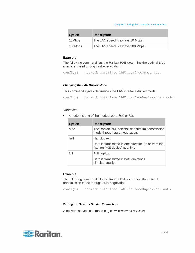
Chapter 7: Using the Command Line Interface
179
Option Description
10Mbps The LAN speed is always 10 Mbps.
100Mbps The LAN speed is always 100 Mbps.
Example
The following command lets the Raritan PXE determine the optimal LAN interface speed through auto-negotiation.
config:# network interface LANInterfaceSpeed auto
Changing the LAN Duplex Mode
This command syntax determines the LAN interface duplex mode.
config:# network interface LANInterfaceDuplexMode <mode>
Variables:
<mode> is one of the modes: auto, half or full.
Option Description
auto The Raritan PXE selects the optimum transmission mode through auto-negotiation.
half Half duplex:
Data is transmitted in one direction (to or from the Raritan PXE device) at a time.
full Full duplex:
Data is transmitted in both directions simultaneously.
Example
The following command lets the Raritan PXE determine the optimal transmission mode through auto-negotiation.
config:# network interface LANInterfaceDuplexMode auto
Setting the Network Service Parameters
A network service command begins with network services.
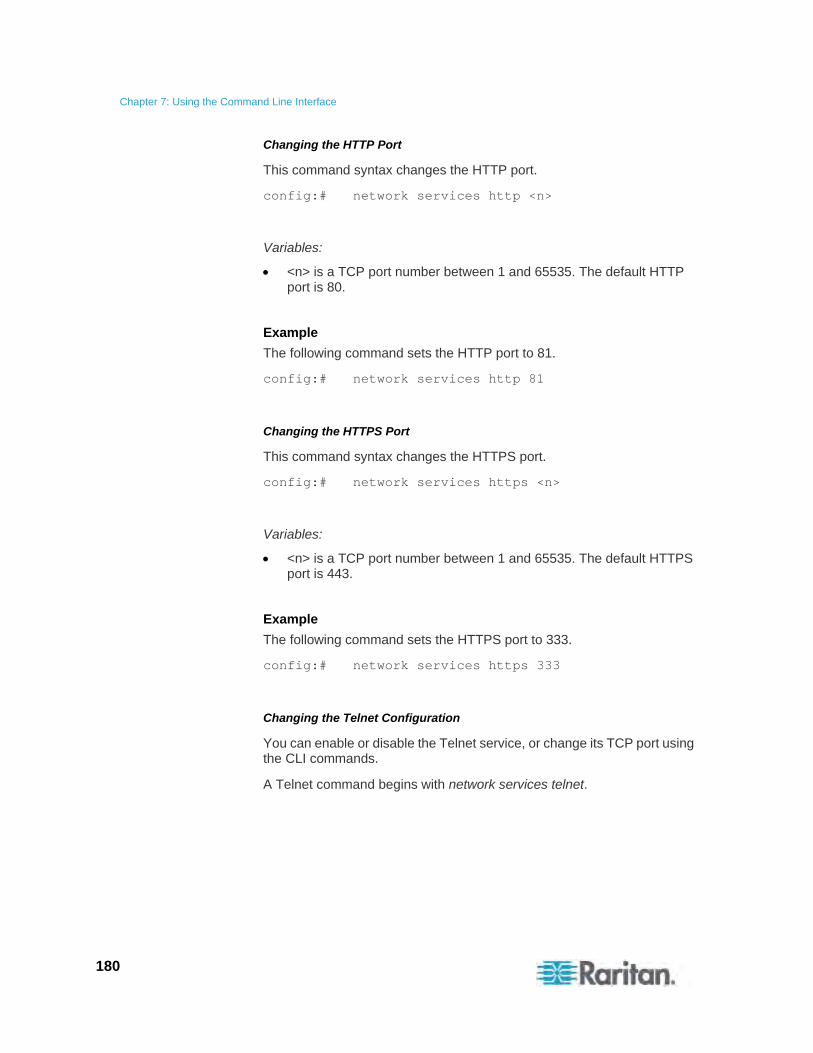
Chapter 7: Using the Command Line Interface
180
Changing the HTTP Port
This command syntax changes the HTTP port.
config:# network services http <n>
Variables:
<n> is a TCP port number between 1 and 65535. The default HTTP port is 80.
Example
The following command sets the HTTP port to 81.
config:# network services http 81
Changing the HTTPS Port
This command syntax changes the HTTPS port.
config:# network services https <n>
Variables:
<n> is a TCP port number between 1 and 65535. The default HTTPS port is 443.
Example
The following command sets the HTTPS port to 333.
config:# network services https 333
Changing the Telnet Configuration
You can enable or disable the Telnet service, or change its TCP port using the CLI commands.
A Telnet command begins with network services telnet.
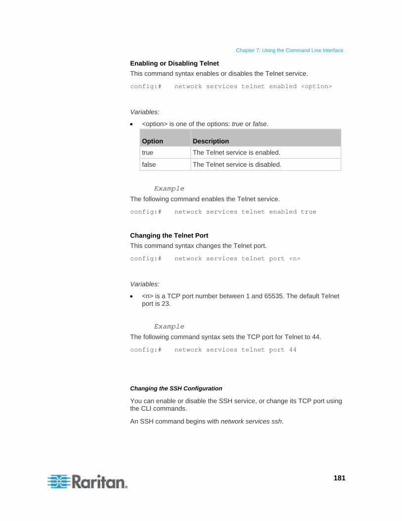
Chapter 7: Using the Command Line Interface
181
Enabling or Disabling Telnet
This command syntax enables or disables the Telnet service.
config:# network services telnet enabled <option>
Variables:
<option> is one of the options: true or false.
Option Description
true The Telnet service is enabled.
false The Telnet service is disabled.
Example
The following command enables the Telnet service.
config:# network services telnet enabled true
Changing the Telnet Port
This command syntax changes the Telnet port.
config:# network services telnet port <n>
Variables:
<n> is a TCP port number between 1 and 65535. The default Telnet port is 23.
Example
The following command syntax sets the TCP port for Telnet to 44.
config:# network services telnet port 44
Changing the SSH Configuration
You can enable or disable the SSH service, or change its TCP port using the CLI commands.
An SSH command begins with network services ssh.
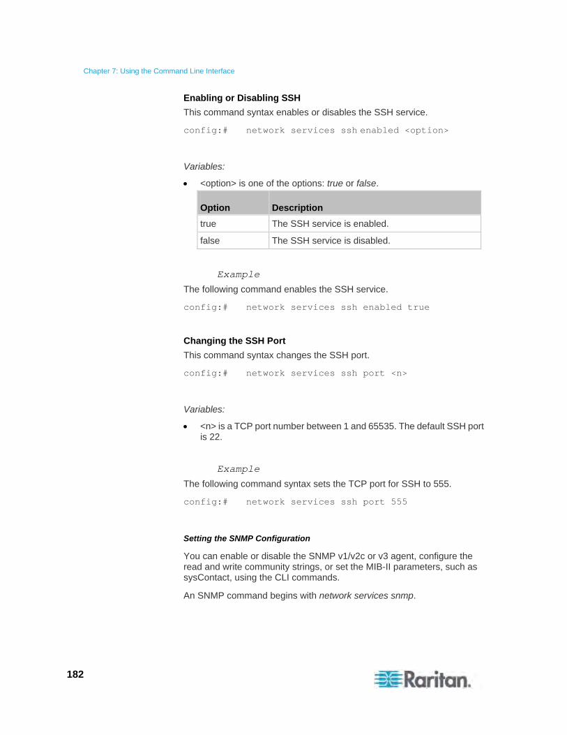
Chapter 7: Using the Command Line Interface
182
Enabling or Disabling SSH
This command syntax enables or disables the SSH service.
config:# network services ssh enabled <option>
Variables:
<option> is one of the options: true or false.
Option Description
true The SSH service is enabled.
false The SSH service is disabled.
Example
The following command enables the SSH service.
config:# network services ssh enabled true
Changing the SSH Port
This command syntax changes the SSH port.
config:# network services ssh port <n>
Variables:
<n> is a TCP port number between 1 and 65535. The default SSH port is 22.
Example
The following command syntax sets the TCP port for SSH to 555.
config:# network services ssh port 555
Setting the SNMP Configuration
You can enable or disable the SNMP v1/v2c or v3 agent, configure the read and write community strings, or set the MIB-II parameters, such as sysContact, using the CLI commands.
An SNMP command begins with network services snmp.
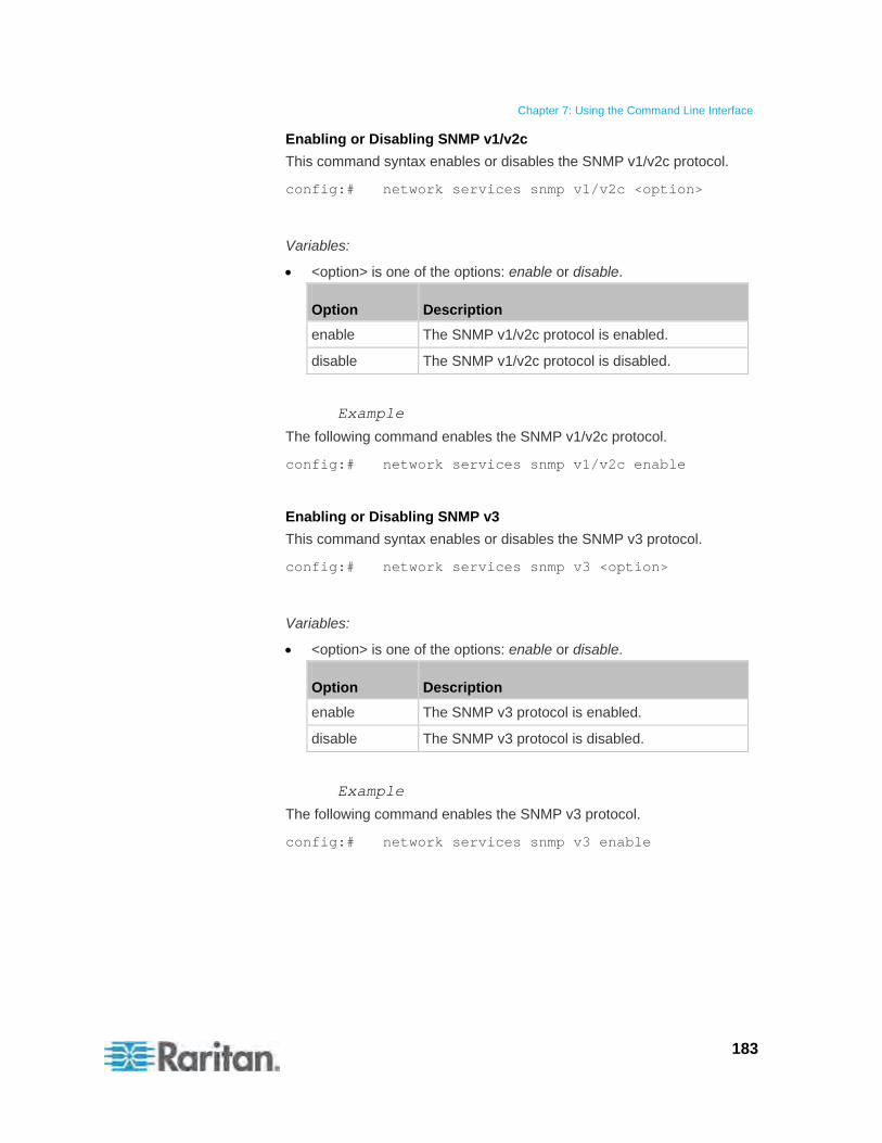
Chapter 7: Using the Command Line Interface
183
Enabling or Disabling SNMP v1/v2c
This command syntax enables or disables the SNMP v1/v2c protocol.
config:# network services snmp v1/v2c <option>
Variables:
<option> is one of the options: enable or disable.
Option Description
enable The SNMP v1/v2c protocol is enabled.
disable The SNMP v1/v2c protocol is disabled.
Example
The following command enables the SNMP v1/v2c protocol.
config:# network services snmp v1/v2c enable
Enabling or Disabling SNMP v3
This command syntax enables or disables the SNMP v3 protocol.
config:# network services snmp v3 <option>
Variables:
<option> is one of the options: enable or disable.
Option Description
enable The SNMP v3 protocol is enabled.
disable The SNMP v3 protocol is disabled.
Example
The following command enables the SNMP v3 protocol.
config:# network services snmp v3 enable
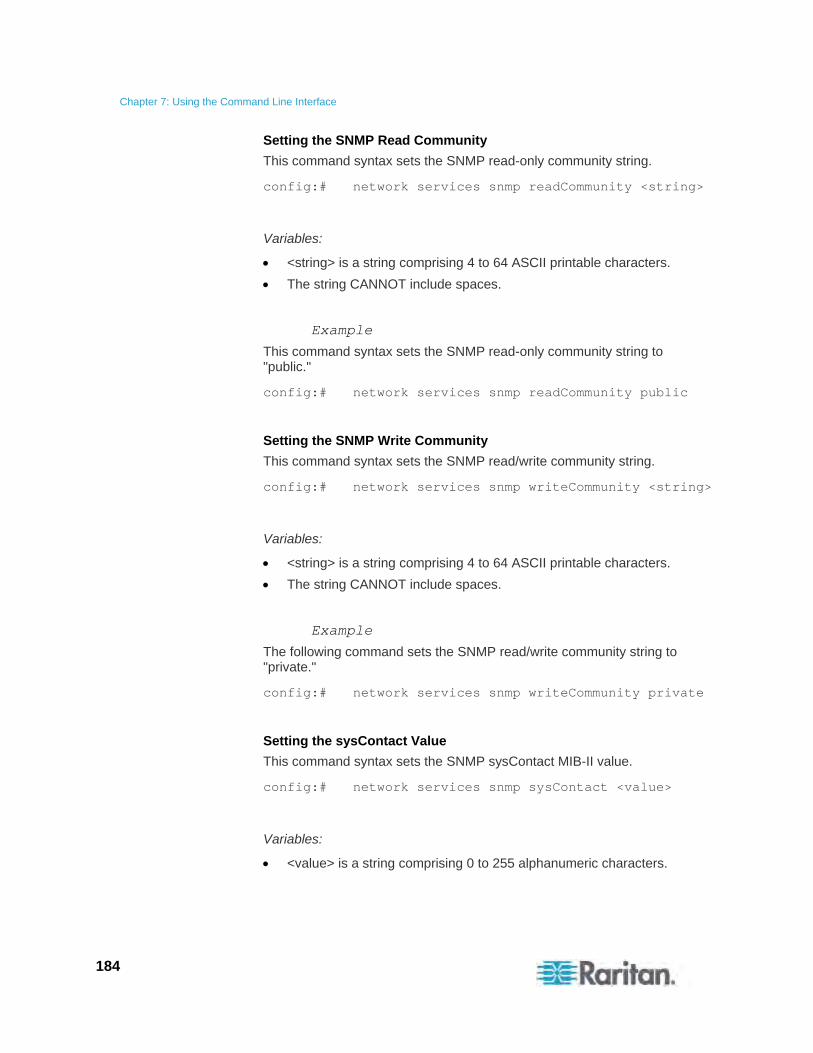
Chapter 7: Using the Command Line Interface
184
Setting the SNMP Read Community
This command syntax sets the SNMP read-only community string.
config:# network services snmp readCommunity <string>
Variables:
<string> is a string comprising 4 to 64 ASCII printable characters.
The string CANNOT include spaces.
Example
This command syntax sets the SNMP read-only community string to "public."
config:# network services snmp readCommunity public
Setting the SNMP Write Community
This command syntax sets the SNMP read/write community string.
config:# network services snmp writeCommunity <string>
Variables:
<string> is a string comprising 4 to 64 ASCII printable characters.
The string CANNOT include spaces.
Example
The following command sets the SNMP read/write community string to "private."
config:# network services snmp writeCommunity private
Setting the sysContact Value
This command syntax sets the SNMP sysContact MIB-II value.
config:# network services snmp sysContact <value>
Variables:
<value> is a string comprising 0 to 255 alphanumeric characters.
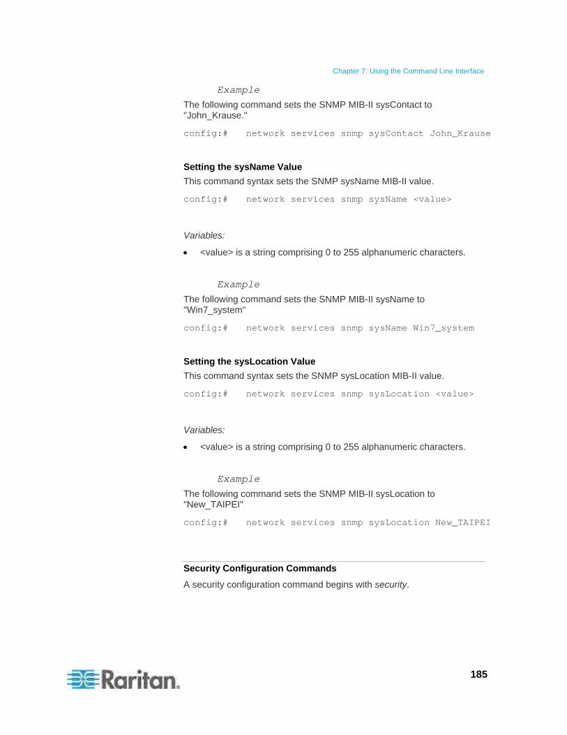
Chapter 7: Using the Command Line Interface
185
Example
The following command sets the SNMP MIB-II sysContact to "John_Krause."
config:# network services snmp sysContact John_Krause
Setting the sysName Value
This command syntax sets the SNMP sysName MIB-II value.
config:# network services snmp sysName <value>
Variables:
<value> is a string comprising 0 to 255 alphanumeric characters.
Example
The following command sets the SNMP MIB-II sysName to "Win7_system"
config:# network services snmp sysName Win7_system
Setting the sysLocation Value
This command syntax sets the SNMP sysLocation MIB-II value.
config:# network services snmp sysLocation <value>
Variables:
<value> is a string comprising 0 to 255 alphanumeric characters.
Example
The following command sets the SNMP MIB-II sysLocation to "New_TAIPEI"
config:# network services snmp sysLocation New_TAIPEI
Security Configuration Commands
A security configuration command begins with security.
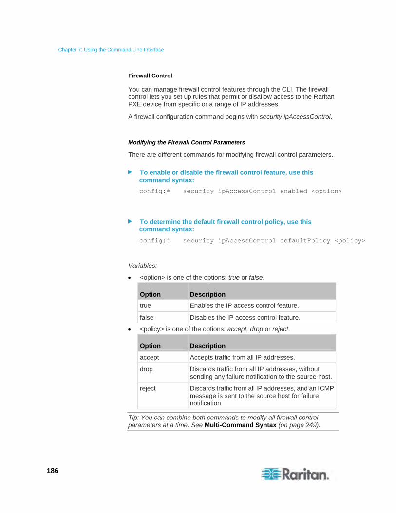
Chapter 7: Using the Command Line Interface
186
Firewall Control
You can manage firewall control features through the CLI. The firewall control lets you set up rules that permit or disallow access to the Raritan PXE device from specific or a range of IP addresses.
A firewall configuration command begins with security ipAccessControl.
Modifying the Firewall Control Parameters
There are different commands for modifying firewall control parameters.
To enable or disable the firewall control feature, use this command syntax:
config:# security ipAccessControl enabled <option>
To determine the default firewall control policy, use this command syntax:
config:# security ipAccessControl defaultPolicy <policy>
Variables:
<option> is one of the options: true or false.
Option Description
true Enables the IP access control feature.
false Disables the IP access control feature.
<policy> is one of the options: accept, drop or reject.
Option Description
accept Accepts traffic from all IP addresses.
drop Discards traffic from all IP addresses, without sending any failure notification to the source host.
reject Discards traffic from all IP addresses, and an ICMP message is sent to the source host for failure notification.
Tip: You can combine both commands to modify all firewall control parameters at a time. See Multi-Command Syntax (on page 249).
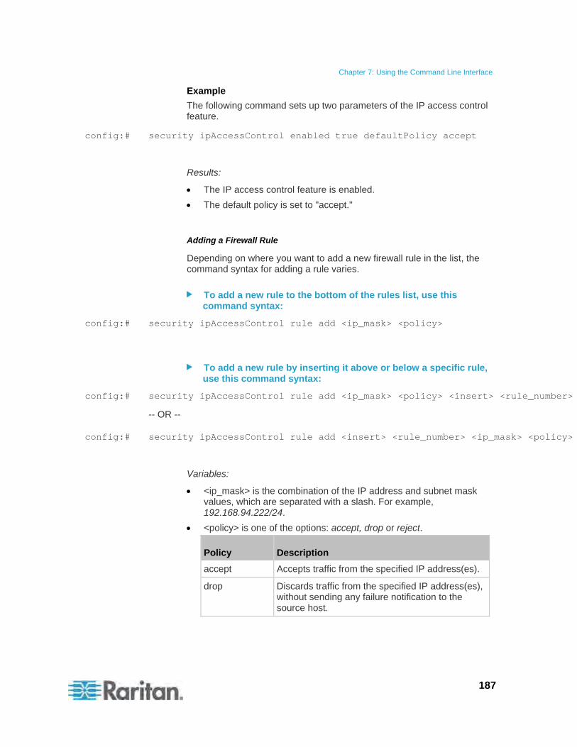
Chapter 7: Using the Command Line Interface
187
Example
The following command sets up two parameters of the IP access control feature.
config:# security ipAccessControl enabled true defaultPolicy accept
Results:
The IP access control feature is enabled.
The default policy is set to "accept."
Adding a Firewall Rule
Depending on where you want to add a new firewall rule in the list, the command syntax for adding a rule varies.
To add a new rule to the bottom of the rules list, use this command syntax:
config:# security ipAccessControl rule add <ip_mask> <policy>
To add a new rule by inserting it above or below a specific rule, use this command syntax:
config:# security ipAccessControl rule add <ip_mask> <policy> <insert> <rule_number>
-- OR --
config:# security ipAccessControl rule add <insert> <rule_number> <ip_mask> <policy>
Variables:
<ip_mask> is the combination of the IP address and subnet mask values, which are separated with a slash. For example, 192.168.94.222/24.
<policy> is one of the options: accept, drop or reject.
Policy Description
accept Accepts traffic from the specified IP address(es).
drop Discards traffic from the specified IP address(es), without sending any failure notification to the source host.

Chapter 7: Using the Command Line Interface
188
Policy Description
reject Discards traffic from the specified IP address(es), and an ICMP message is sent to the source host for failure notification.
<insert> is one of the options: insertAbove or insertBelow.
Option Description
insertAbove Inserts the new rule above the specified rule number. Then:
new rule's number = the specified rule number
insertBelow Inserts the new rule below the specified rule number. Then:
new rule's number = the specified rule number + 1
<rule_number> is the number of the existing rule which you want to insert the new rule above or below.
Example
The following command adds a new IP access control rule and specifies its location in the list.
config:# security ipAccessControl rule add 192.168.84.123/24 accept insertAbove 5
Results:
A new firewall control rule is added, allowing all packets from the IP address 192.168.84.123 to be accepted.
The newly-added rule is inserted above the 5th rule. That is, the new rule becomes the 5th rule, and the original 5th rule becomes the 6th rule.
Managing Firewall Rules
You can add, delete or modify firewall rules using the CLI commands. A firewall control rule command begins with security ipAccessControl rule.
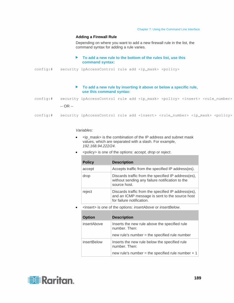
Chapter 7: Using the Command Line Interface
189
Adding a Firewall Rule
Depending on where you want to add a new firewall rule in the list, the command syntax for adding a rule varies.
To add a new rule to the bottom of the rules list, use this command syntax:
config:# security ipAccessControl rule add <ip_mask> <policy>
To add a new rule by inserting it above or below a specific rule, use this command syntax:
config:# security ipAccessControl rule add <ip_mask> <policy> <insert> <rule_number>
-- OR --
config:# security ipAccessControl rule add <insert> <rule_number> <ip_mask> <policy>
Variables:
<ip_mask> is the combination of the IP address and subnet mask values, which are separated with a slash. For example, 192.168.94.222/24.
<policy> is one of the options: accept, drop or reject.
Policy Description
accept Accepts traffic from the specified IP address(es).
drop Discards traffic from the specified IP address(es), without sending any failure notification to the source host.
reject Discards traffic from the specified IP address(es), and an ICMP message is sent to the source host for failure notification.
<insert> is one of the options: insertAbove or insertBelow.
Option Description
insertAbove Inserts the new rule above the specified rule number. Then:
new rule's number = the specified rule number
insertBelow Inserts the new rule below the specified rule number. Then:
new rule's number = the specified rule number + 1
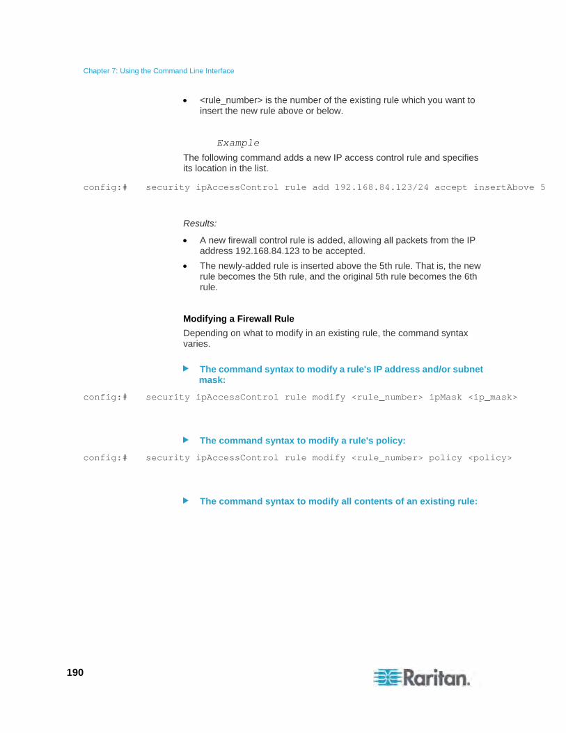
Chapter 7: Using the Command Line Interface
190
<rule_number> is the number of the existing rule which you want to insert the new rule above or below.
Example
The following command adds a new IP access control rule and specifies its location in the list.
config:# security ipAccessControl rule add 192.168.84.123/24 accept insertAbove 5
Results:
A new firewall control rule is added, allowing all packets from the IP address 192.168.84.123 to be accepted.
The newly-added rule is inserted above the 5th rule. That is, the new rule becomes the 5th rule, and the original 5th rule becomes the 6th rule.
Modifying a Firewall Rule
Depending on what to modify in an existing rule, the command syntax varies.
The command syntax to modify a rule's IP address and/or subnet mask:
config:# security ipAccessControl rule modify <rule_number> ipMask <ip_mask>
The command syntax to modify a rule's policy:
config:# security ipAccessControl rule modify <rule_number> policy <policy>
The command syntax to modify all contents of an existing rule:
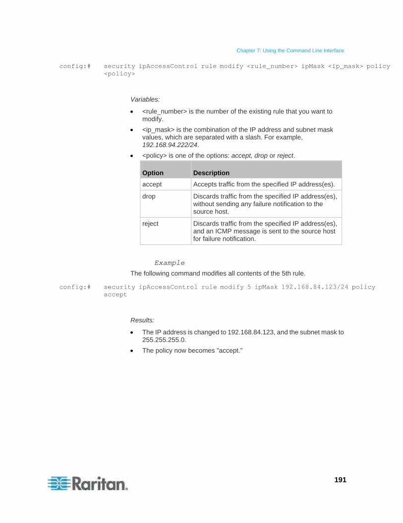
Chapter 7: Using the Command Line Interface
191
config:# security ipAccessControl rule modify <rule_number> ipMask <ip_mask> policy <policy>
Variables:
<rule_number> is the number of the existing rule that you want to modify.
<ip_mask> is the combination of the IP address and subnet mask values, which are separated with a slash. For example, 192.168.94.222/24.
<policy> is one of the options: accept, drop or reject.
Option Description
accept Accepts traffic from the specified IP address(es).
drop Discards traffic from the specified IP address(es), without sending any failure notification to the source host.
reject Discards traffic from the specified IP address(es), and an ICMP message is sent to the source host for failure notification.
Example
The following command modifies all contents of the 5th rule.
config:# security ipAccessControl rule modify 5 ipMask 192.168.84.123/24 policy accept
Results:
The IP address is changed to 192.168.84.123, and the subnet mask to 255.255.255.0.
The policy now becomes "accept."
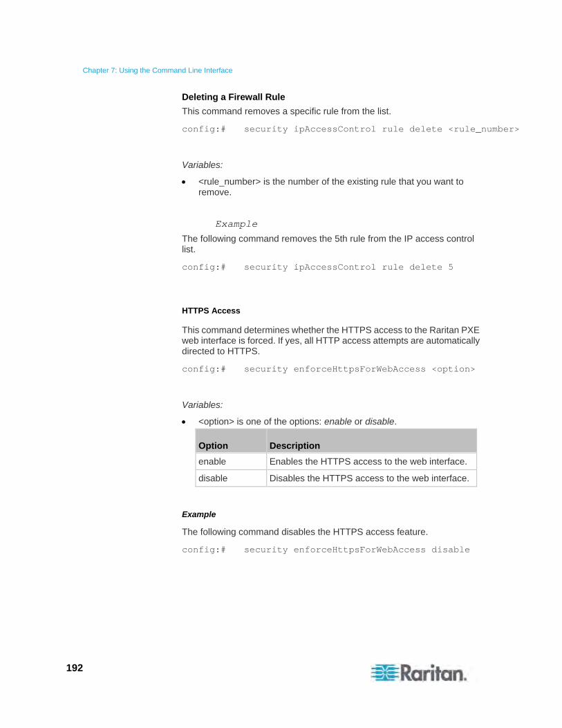
Chapter 7: Using the Command Line Interface
192
Deleting a Firewall Rule
This command removes a specific rule from the list.
config:# security ipAccessControl rule delete <rule_number>
Variables:
<rule_number> is the number of the existing rule that you want to remove.
Example
The following command removes the 5th rule from the IP access control list.
config:# security ipAccessControl rule delete 5
HTTPS Access
This command determines whether the HTTPS access to the Raritan PXE web interface is forced. If yes, all HTTP access attempts are automatically directed to HTTPS.
config:# security enforceHttpsForWebAccess <option>
Variables:
<option> is one of the options: enable or disable.
Option Description
enable Enables the HTTPS access to the web interface.
disable Disables the HTTPS access to the web interface.
Example
The following command disables the HTTPS access feature.
config:# security enforceHttpsForWebAccess disable

Chapter 7: Using the Command Line Interface
193
Login Limitation
The login limitation feature controls login-related limitations, such as password aging, simultaneous logins using the same user name, and the idle time permitted before being forced to log out.
A login limitation command begins with security loginLimits.
You can combine multiple commands to modify the login limitation parameters at a time. See Multi-Command Syntax (on page 249).
Single Login Limitation
This command syntax enables or disables the single login feature, which controls whether multiple logins using the same login name simultaneously is permitted.
config:# security loginLimits singleLogin <option>
Variables:
<option> is one of the options: enable or disable.
Option Description
enable Enables the single login feature.
disable Disables the single login feature.
Example
The following command disables the single login feature so that more than one user can log in using the same user name at the same time.
config:# security loginLimits singleLogin disable
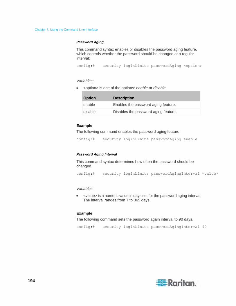
Chapter 7: Using the Command Line Interface
194
Password Aging
This command syntax enables or disables the password aging feature, which controls whether the password should be changed at a regular interval:
config:# security loginLimits passwordAging <option>
Variables:
<option> is one of the options: enable or disable.
Option Description
enable Enables the password aging feature.
disable Disables the password aging feature.
Example
The following command enables the password aging feature.
config:# security loginLimits passwordAging enable
Password Aging Interval
This command syntax determines how often the password should be changed.
config:# security loginLimits passwordAgingInterval <value>
Variables:
<value> is a numeric value in days set for the password aging interval. The interval ranges from 7 to 365 days.
Example
The following command sets the password again interval to 90 days.
config:# security loginLimits passwordAgingInterval 90

Chapter 7: Using the Command Line Interface
195
Idle Timeout
This command syntax determines how long a user can remain idle before that user is forced to log out of the Raritan PXE web interface.
config:# security loginLimits idleTimeout <value>
Variables:
<value> is a numeric value in minutes set for the idle timeout. The timeout ranges from 1 to 1440 minutes (24 hours).
Example
The following command sets the idle timeout to 10 munites.
config:# security loginLimits idleTimeout 10
User Blocking
There are different commands for changing different user blocking parameters. These commands begin with security userBlocking.
To determine the maximum number of failed logins before blocking a user, use this command syntax:
config:# security userBlocking maximumNumberOfFailedLogins <value1>
To determine how long a user's login is blocked, use this command syntax:
config:# security userBlocking blockTime <value2>
Variables:
<value1> is an integer between 3 and 10, or unlimited, which sets no limit on the maximum number of failed logins and thus disables the user blocking function.
<value2> is a numeric value in minutes.
Tip: You can combine multiple commands to modify the user blocking parameters at a time. See Multi-Command Syntax (on page 249).
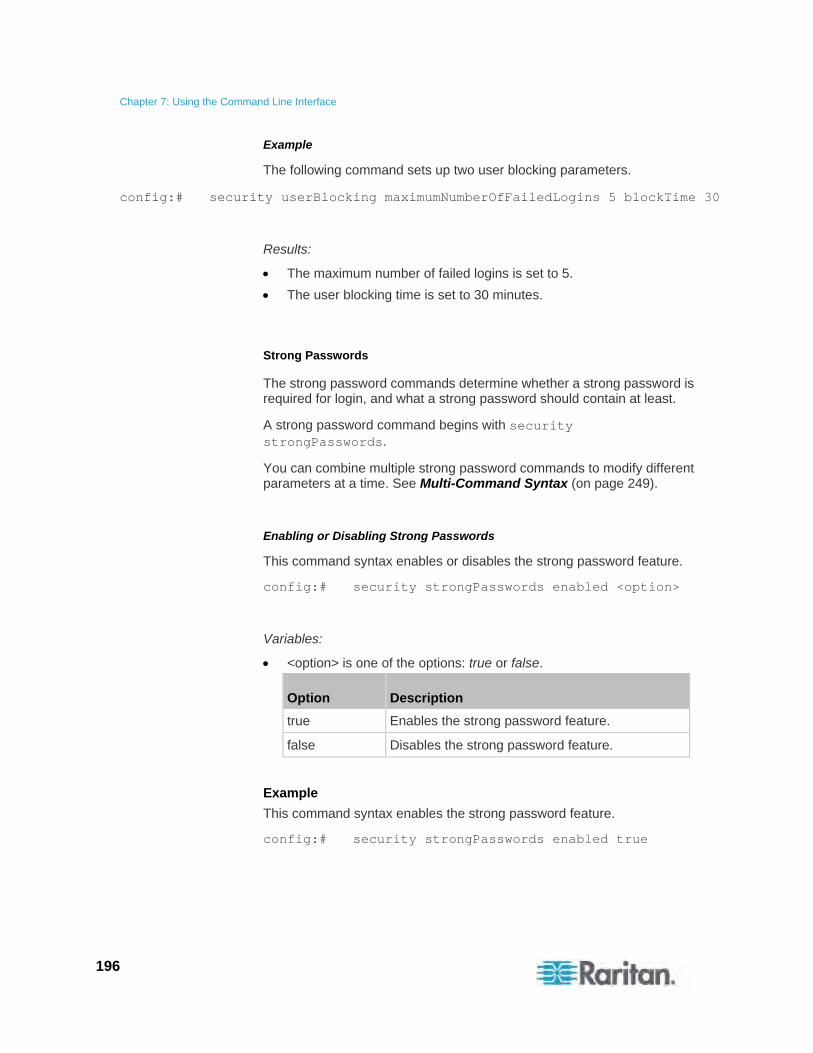
Chapter 7: Using the Command Line Interface
196
Example
The following command sets up two user blocking parameters.
config:# security userBlocking maximumNumberOfFailedLogins 5 blockTime 30
Results:
The maximum number of failed logins is set to 5.
The user blocking time is set to 30 minutes.
Strong Passwords
The strong password commands determine whether a strong password is required for login, and what a strong password should contain at least.
A strong password command begins with security strongPasswords.
You can combine multiple strong password commands to modify different parameters at a time. See Multi-Command Syntax (on page 249).
Enabling or Disabling Strong Passwords
This command syntax enables or disables the strong password feature.
config:# security strongPasswords enabled <option>
Variables:
<option> is one of the options: true or false.
Option Description
true Enables the strong password feature.
false Disables the strong password feature.
Example
This command syntax enables the strong password feature.
config:# security strongPasswords enabled true
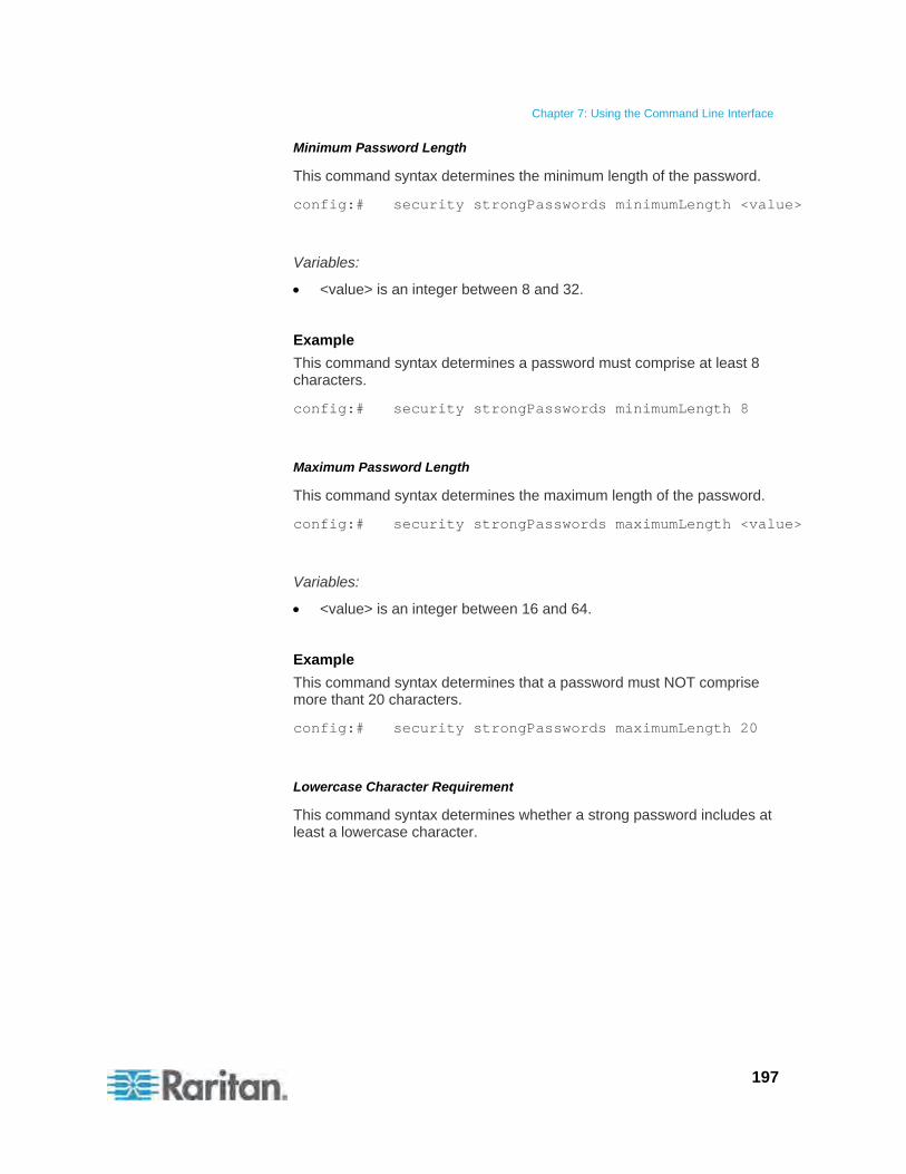
Chapter 7: Using the Command Line Interface
197
Minimum Password Length
This command syntax determines the minimum length of the password.
config:# security strongPasswords minimumLength <value>
Variables:
<value> is an integer between 8 and 32.
Example
This command syntax determines a password must comprise at least 8 characters.
config:# security strongPasswords minimumLength 8
Maximum Password Length
This command syntax determines the maximum length of the password.
config:# security strongPasswords maximumLength <value>
Variables:
<value> is an integer between 16 and 64.
Example
This command syntax determines that a password must NOT comprise more thant 20 characters.
config:# security strongPasswords maximumLength 20
Lowercase Character Requirement
This command syntax determines whether a strong password includes at least a lowercase character.
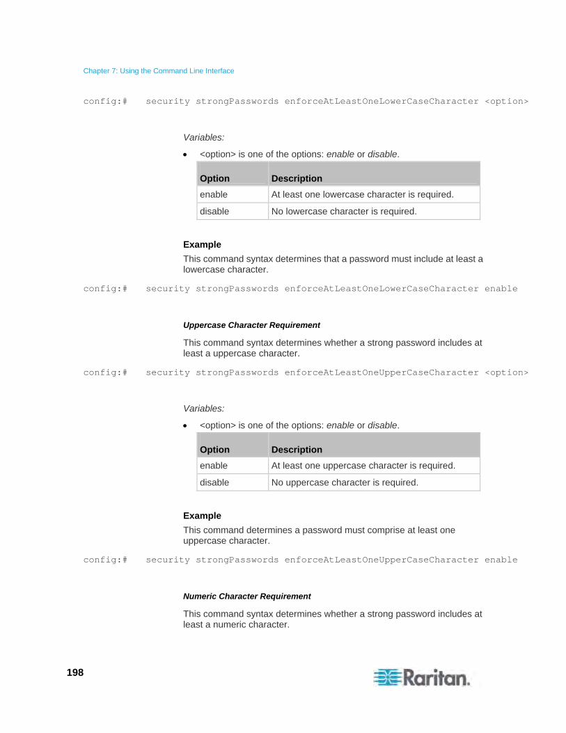
Chapter 7: Using the Command Line Interface
198
config:# security strongPasswords enforceAtLeastOneLowerCaseCharacter <option>
Variables:
<option> is one of the options: enable or disable.
Option Description
enable At least one lowercase character is required.
disable No lowercase character is required.
Example
This command syntax determines that a password must include at least a lowercase character.
config:# security strongPasswords enforceAtLeastOneLowerCaseCharacter enable
Uppercase Character Requirement
This command syntax determines whether a strong password includes at least a uppercase character.
config:# security strongPasswords enforceAtLeastOneUpperCaseCharacter <option>
Variables:
<option> is one of the options: enable or disable.
Option Description
enable At least one uppercase character is required.
disable No uppercase character is required.
Example
This command determines a password must comprise at least one uppercase character.
config:# security strongPasswords enforceAtLeastOneUpperCaseCharacter enable
Numeric Character Requirement
This command syntax determines whether a strong password includes at least a numeric character.

Chapter 7: Using the Command Line Interface
199
config:# security strongPasswords enforceAtLeastOneNumericCharacter <option>
Variables:
<option> is one of the options: enable or disable.
Option Description
enable At least one numeric character is required.
disable No numeric character is required.
Example
The following command determines that a password must comprise at least one numeric character.
config:# security strongPasswords enforceAtLeastOneNumericCharacter enable
Special Character Requirement
This command syntax determines whether a strong password includes at least a special character.
config:# security strongPasswords enforceAtLeastOneSpecialCharacter <option>
Variables:
<option> is one of the options: enable or disable.
Option Description
enable At least one special character is required.
disable No special character is required.
Example
The following command determines that a password must comprise at least one special character.
config:# security strongPasswords enforceAtLeastOneSpecialCharacter enable
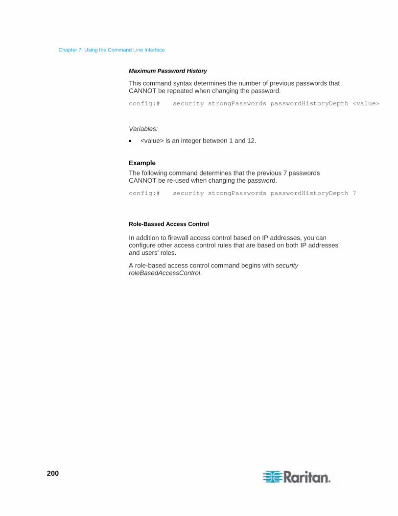
Chapter 7: Using the Command Line Interface
200
Maximum Password History
This command syntax determines the number of previous passwords that CANNOT be repeated when changing the password.
config:# security strongPasswords passwordHistoryDepth <value>
Variables:
<value> is an integer between 1 and 12.
Example
The following command determines that the previous 7 passwords CANNOT be re-used when changing the password.
config:# security strongPasswords passwordHistoryDepth 7
Role-Bassed Access Control
In addition to firewall access control based on IP addresses, you can configure other access control rules that are based on both IP addresses and users' roles.
A role-based access control command begins with security roleBasedAccessControl.
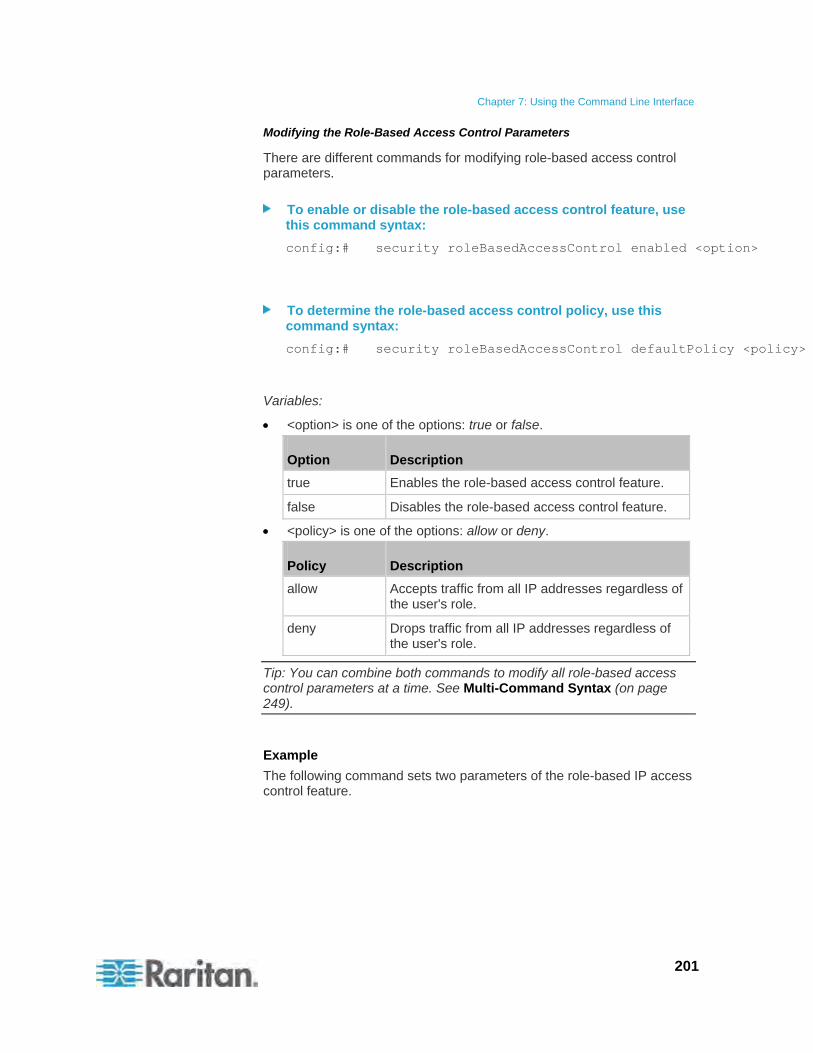
Chapter 7: Using the Command Line Interface
201
Modifying the Role-Based Access Control Parameters
There are different commands for modifying role-based access control parameters.
To enable or disable the role-based access control feature, use this command syntax:
config:# security roleBasedAccessControl enabled <option>
To determine the role-based access control policy, use this command syntax:
config:# security roleBasedAccessControl defaultPolicy <policy>
Variables:
<option> is one of the options: true or false.
Option Description
true Enables the role-based access control feature.
false Disables the role-based access control feature.
<policy> is one of the options: allow or deny.
Policy Description
allow Accepts traffic from all IP addresses regardless of the user's role.
deny Drops traffic from all IP addresses regardless of the user's role.
Tip: You can combine both commands to modify all role-based access control parameters at a time. See Multi-Command Syntax (on page 249).
Example
The following command sets two parameters of the role-based IP access control feature.
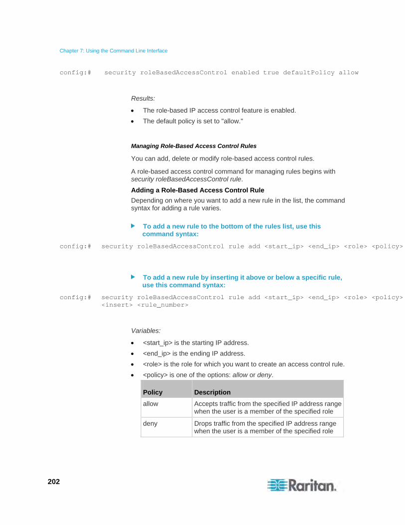
Chapter 7: Using the Command Line Interface
202
config:# security roleBasedAccessControl enabled true defaultPolicy allow
Results:
The role-based IP access control feature is enabled.
The default policy is set to "allow."
Managing Role-Based Access Control Rules
You can add, delete or modify role-based access control rules.
A role-based access control command for managing rules begins with security roleBasedAccessControl rule.
Adding a Role-Based Access Control Rule
Depending on where you want to add a new rule in the list, the command syntax for adding a rule varies.
To add a new rule to the bottom of the rules list, use this command syntax:
config:# security roleBasedAccessControl rule add <start_ip> <end_ip> <role> <policy>
To add a new rule by inserting it above or below a specific rule, use this command syntax:
config:# security roleBasedAccessControl rule add <start_ip> <end_ip> <role> <policy> <insert> <rule_number>
Variables:
<start_ip> is the starting IP address.
<end_ip> is the ending IP address.
<role> is the role for which you want to create an access control rule.
<policy> is one of the options: allow or deny.
Policy Description
allow Accepts traffic from the specified IP address range when the user is a member of the specified role
deny Drops traffic from the specified IP address range when the user is a member of the specified role
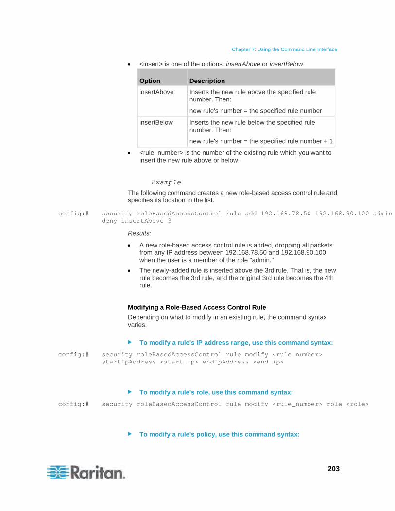
Chapter 7: Using the Command Line Interface
203
<insert> is one of the options: insertAbove or insertBelow.
Option Description
insertAbove Inserts the new rule above the specified rule number. Then:
new rule's number = the specified rule number
insertBelow Inserts the new rule below the specified rule number. Then:
new rule's number = the specified rule number + 1
<rule_number> is the number of the existing rule which you want to insert the new rule above or below.
Example
The following command creates a new role-based access control rule and specifies its location in the list.
config:# security roleBasedAccessControl rule add 192.168.78.50 192.168.90.100 admin deny insertAbove 3
Results:
A new role-based access control rule is added, dropping all packets from any IP address between 192.168.78.50 and 192.168.90.100 when the user is a member of the role "admin."
The newly-added rule is inserted above the 3rd rule. That is, the new rule becomes the 3rd rule, and the original 3rd rule becomes the 4th rule.
Modifying a Role-Based Access Control Rule
Depending on what to modify in an existing rule, the command syntax varies.
To modify a rule's IP address range, use this command syntax:
config:# security roleBasedAccessControl rule modify <rule_number> startIpAddress <start_ip> endIpAddress <end_ip>
To modify a rule's role, use this command syntax:
config:# security roleBasedAccessControl rule modify <rule_number> role <role>
To modify a rule's policy, use this command syntax:
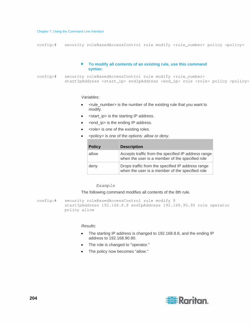
Chapter 7: Using the Command Line Interface
204
config:# security roleBasedAccessControl rule modify <rule_number> policy <policy>
To modify all contents of an existing rule, use this command syntax:
config:# security roleBasedAccessControl rule modify <rule_number> startIpAddress <start_ip> endIpAddress <end_ip> role <role> policy <policy>
Variables:
<rule_number> is the number of the existing rule that you want to modify.
<start_ip> is the starting IP address.
<end_ip> is the ending IP address.
<role> is one of the existing roles.
<policy> is one of the options: allow or deny.
Policy Description
allow Accepts traffic from the specified IP address range when the user is a member of the specified role
deny Drops traffic from the specified IP address range when the user is a member of the specified role
Example
The following command modifies all contents of the 8th rule.
config:# security roleBasedAccessControl rule modify 8 startIpAddress 192.168.8.8 endIpAddress 192.168.90.90 role operator policy allow
Results:
The starting IP address is changed to 192.168.8.8, and the ending IP address to 192.168.90.90.
The role is changed to "operator."
The policy now becomes "allow."
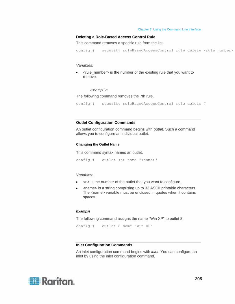
Chapter 7: Using the Command Line Interface
205
Deleting a Role-Based Access Control Rule
This command removes a specific rule from the list.
config:# security roleBasedAccessControl rule delete <rule_number>
Variables:
<rule_number> is the number of the existing rule that you want to remove.
Example
The following command removes the 7th rule.
config:# security roleBasedAccessControl rule delete 7
Outlet Configuration Commands
An outlet configuration command begins with outlet. Such a command allows you to configure an individual outlet.
Changing the Outlet Name
This command syntax names an outlet.
config:# outlet <n> name "<name>"
Variables:
<n> is the number of the outlet that you want to configure.
<name> is a string comprising up to 32 ASCII printable characters. The <name> variable must be enclosed in quotes when it contains spaces.
Example
The following command assigns the name "Win XP" to outlet 8.
config:# outlet 8 name "Win XP"
Inlet Configuration Commands
An inlet configuration command begins with inlet. You can configure an inlet by using the inlet configuration command.

Chapter 7: Using the Command Line Interface
206
Changing the Inlet Name
This command syntax names an inlet.
config:# inlet <n> name "<name>"
Variables:
<n> is the number of the inlet that you want to configure. For a single-inlet PDU, <n> is always the number 1. The value is an integer between 1 and 50.
<name> is a string comprising up to 32 ASCII printable characters. The <name> variable must be enclosed in quotes when it contains spaces.
Example
The following command assigns the name "AC source" to the inlet 1. If your Raritan PXE device contains multiple inlets, this command names the 1st inlet.
config:# inlet 1 name "AC source"
Circuit Breaker Configuration Commands
A circuit breaker configuration command begins with ocp. The command configures an individual circuit breaker.
Changing the Circuit Breaker Name
This command syntax names a circuit breaker.
config:# ocp <n> name "<name>"
Variables:
<n> is the number of the circuit breaker that you want to configure. The value is an integer between 1 and 50.
<name> is a string comprising up to 32 ASCII printable characters. The <name> variable must be enclosed in quotes when it contains spaces.
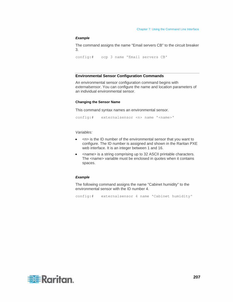
Chapter 7: Using the Command Line Interface
207
Example
The command assigns the name "Email servers CB" to the circuit breaker 3.
config:# ocp 3 name "Email servers CB"
Environmental Sensor Configuration Commands
An environmental sensor configuration command begins with externalsensor. You can configure the name and location parameters of an individual environmental sensor.
Changing the Sensor Name
This command syntax names an environmental sensor.
config:# externalsensor <n> name "<name>"
Variables:
<n> is the ID number of the environmental sensor that you want to configure. The ID number is assigned and shown in the Raritan PXE web interface. It is an integer between 1 and 16.
<name> is a string comprising up to 32 ASCII printable characters. The <name> variable must be enclosed in quotes when it contains spaces.
Example
The following command assigns the name "Cabinet humidity" to the environmental sensor with the ID number 4.
config:# externalsensor 4 name "Cabinet humidity"
Chapter 7: Using the Command Line Interface
208
Specifying the Sensor Type
Raritan's contact closure sensor (DPX-CC2-TR) supports the connection of diverse third-party detectors/switches, and you must specify the type of connected detector/switch for proper operation. Use this command syntax when you need to specify the sensor type.
config:# externalsensor <n> sensorSubType <type>
Variables:
<n> is the ID number of the environmental sensor that you want to configure. The ID number is assigned and shown in the Raritan PXE web interface. It is an integer between 1 and 16.
<type> is one of these types: contact, smokeDetection, waterDetection or vibration.
Type Description
contact The connected detector/switch is for detection of door lock or door closed/open status.
smokeDetection The connected detector/switch is for detection of the smoke presence.
waterDetection The connected detector/switch is for detection of the water presence.
vibration The connected detector/switch is for detection of the vibration.
Example
The following indicates that a smoke detector is being connected to Raritan's contact closure sensor (DPX-CC2-TR) whose ID number shown in the Raritan PXE web interface is 2.
config:# externalsensor 2 sensorSubType smokeDetection
Chapter 7: Using the Command Line Interface
209
Setting the X Coordinate
This command syntax specifies the X coordinate of an environmental sensor.
config:# externalsensor <n> xlabel "<coordinate>"
Variables:
<n> is the ID number of the environmental sensor that you want to configure. The ID number is assigned and shown in the Raritan PXE web interface. It is an integer between 1 and 16.
<coordinate> is a string comprising up to 24 ASCII printable characters, and it must be enclosed in quotes.
Example
The following command sets the value "The 2nd cabinet" to the X coordinate of the environmental sensor with the ID number 4.
config:# externalsensor 4 xlabel "The 2nd cabinet"
Setting the Y Coordinate
This command syntax specifies the Y coordinate of an environmental sensor.
config:# externalsensor <n> ylabel "<coordinate>"
Variables:
<n> is the ID number of the environmental sensor that you want to configure. The ID number is assigned and shown in the Raritan PXE web interface. It is an integer between 1 and 16.
<coordinate> is a string comprising up to 24 ASCII printable characters, and it must be enclosed in quotes.
Example
The following command sets the value "The 4th row" to the Y coordinate of the environmental sensor with the ID number 4.
config:# externalsensor 4 ylabel "The 4th row"
Chapter 7: Using the Command Line Interface
210
Setting the Z Coordinate
This command syntax specifies the Z coordinate of an environmental sensor.
config:# externalsensor <n> zlabel "<coordinate>"
Variables:
<n> is the ID number of the environmental sensor that you want to configure. The ID number is assigned and shown in the Raritan PXE web interface. It is an integer between 1 and 16.
Depending on the Z coordinate format you set, there are two types of values for the <coordinate> variable:
Type Description
Free form <coordinate> is a string comprising up to 24 ASCII printable characters, and it must be enclosed in quotes.
Rack units <coordinate> is an integer number in rack units.
Note: To specify the Z coordinate using the rack units. See Setting the Z Coordinate Format for Environmental Sensors (on page 168).
Example
The following command sets the value "The 5th rack" to the Z coordinate of the environmental sensor with the ID number 4 after the Z coordinate's format is set to freeForm.
config:# externalsensor 4 zlabel "The 5th rack"
Chapter 7: Using the Command Line Interface
211
Changing the Sensor Description
This command syntax provides a description for a specific environmental sensor.
config:# externalsensor <n> description "<description>"
Variables:
<n> is the ID number of the environmental sensor that you want to configure. The ID number is assigned and shown in the Raritan PXE web interface. It is an integer between 1 and 16.
<description> is a string comprising up to 64 ASCII printable characters, and it must be enclosed in quotes.
Example
The following command gives the description "humidity detection" to the environmental sensor with the ID number 4.
config:# externalsensor 4 description "humidity detection"
Sensor Threshold Configuration Commands
A sensor configuration command begins with sensor. You can use the commands to configure the threshold, hysteresis and assertion timeout values for any sensor associated with the following items:
Inlets
Inlet poles (for three-phase PDUs only)
Circuit breakers
Environmental sensors
It is permitted to assign a new value to the threshold at any time regardless of whether the threshold is being enabled.
Commands for Inlet Sensors
A sensor configuration command for inlets begins with sensor inlet.
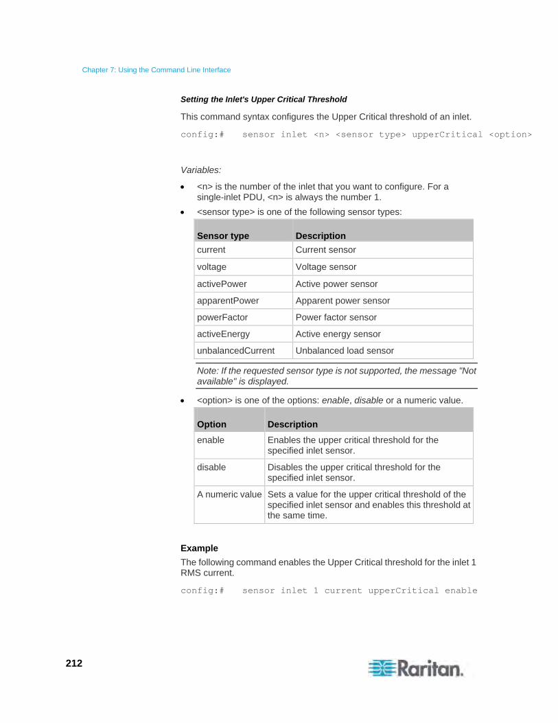
Chapter 7: Using the Command Line Interface
212
Setting the Inlet's Upper Critical Threshold
This command syntax configures the Upper Critical threshold of an inlet.
config:# sensor inlet <n> <sensor type> upperCritical <option>
Variables:
<n> is the number of the inlet that you want to configure. For a single-inlet PDU, <n> is always the number 1.
<sensor type> is one of the following sensor types:
Sensor type Description
current Current sensor
voltage Voltage sensor
activePower Active power sensor
apparentPower Apparent power sensor
powerFactor Power factor sensor
activeEnergy Active energy sensor
unbalancedCurrent Unbalanced load sensor
Note: If the requested sensor type is not supported, the message "Not available" is displayed.
<option> is one of the options: enable, disable or a numeric value.
Option Description
enable Enables the upper critical threshold for the specified inlet sensor.
disable Disables the upper critical threshold for the specified inlet sensor.
A numeric value Sets a value for the upper critical threshold of the specified inlet sensor and enables this threshold at the same time.
Example
The following command enables the Upper Critical threshold for the inlet 1 RMS current.
config:# sensor inlet 1 current upperCritical enable

Chapter 7: Using the Command Line Interface
213
Setting the Inlet's Upper Warning Threshold
This command syntax configures the Upper Warning threshold of an inlet.
config:# sensor inlet <n> <sensor type> upperWarning <option>
Variables:
<n> is the number of the inlet that you want to configure. For a single-inlet PDU, <n> is always the number 1.
<sensor type> is one of the following sensor types:
Sensor type Description
current Current sensor
voltage Voltage sensor
activePower Active power sensor
apparentPower Apparent power sensor
powerFactor Power factor sensor
activeEnergy Active energy sensor
unbalancedCurrent Unbalanced load sensor
Note: If the requested sensor type is not supported, the message "Not available" is displayed.
<option> is one of the options: enable, disable or a numeric value.
Option Description
enable Enables the upper warning threshold for the specified inlet sensor.
disable Disables the upper warning threshold for the specified inlet sensor.
A numeric value Sets a value for the upper warning threshold of the specified inlet sensor and enables this threshold at the same time.
Example
The following command sets the Upper Warning threshold for the inlet 1 RMS current to 12A. It also enables the upper warning threshold if this threshold has not been enabled yet.
config:# sensor inlet 1 current upperWarning 12
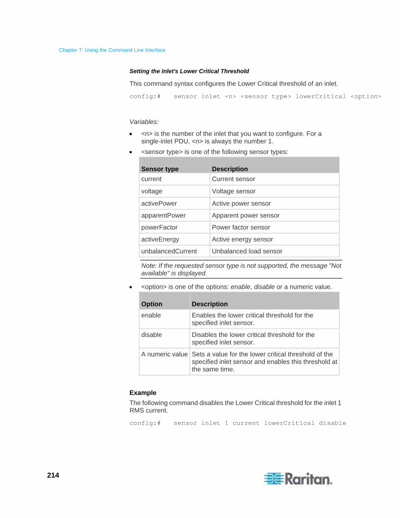
Chapter 7: Using the Command Line Interface
214
Setting the Inlet's Lower Critical Threshold
This command syntax configures the Lower Critical threshold of an inlet.
config:# sensor inlet <n> <sensor type> lowerCritical <option>
Variables:
<n> is the number of the inlet that you want to configure. For a single-inlet PDU, <n> is always the number 1.
<sensor type> is one of the following sensor types:
Sensor type Description
current Current sensor
voltage Voltage sensor
activePower Active power sensor
apparentPower Apparent power sensor
powerFactor Power factor sensor
activeEnergy Active energy sensor
unbalancedCurrent Unbalanced load sensor
Note: If the requested sensor type is not supported, the message "Not available" is displayed.
<option> is one of the options: enable, disable or a numeric value.
Option Description
enable Enables the lower critical threshold for the specified inlet sensor.
disable Disables the lower critical threshold for the specified inlet sensor.
A numeric value Sets a value for the lower critical threshold of the specified inlet sensor and enables this threshold at the same time.
Example
The following command disables the Lower Critical threshold for the inlet 1 RMS current.
config:# sensor inlet 1 current lowerCritical disable
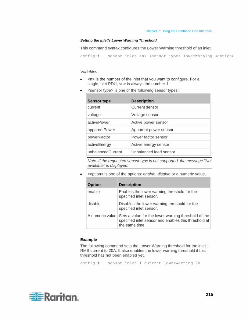
Chapter 7: Using the Command Line Interface
215
Setting the Inlet's Lower Warning Threshold
This command syntax configures the Lower Warning threshold of an inlet.
config:# sensor inlet <n> <sensor type> lowerWarning <option>
Variables:
<n> is the number of the inlet that you want to configure. For a single-inlet PDU, <n> is always the number 1.
<sensor type> is one of the following sensor types:
Sensor type Description
current Current sensor
voltage Voltage sensor
activePower Active power sensor
apparentPower Apparent power sensor
powerFactor Power factor sensor
activeEnergy Active energy sensor
unbalancedCurrent Unbalanced load sensor
Note: If the requested sensor type is not supported, the message "Not available" is displayed.
<option> is one of the options: enable, disable or a numeric value.
Option Description
enable Enables the lower warning threshold for the specified inlet sensor.
disable Disables the lower warning threshold for the specified inlet sensor.
A numeric value Sets a value for the lower warning threshold of the specified inlet sensor and enables this threshold at the same time.
Example
The following command sets the Lower Warning threshold for the inlet 1 RMS current to 20A. It also enables the lower warning threshold if this threshold has not been enabled yet.
config:# sensor inlet 1 current lowerWarning 20
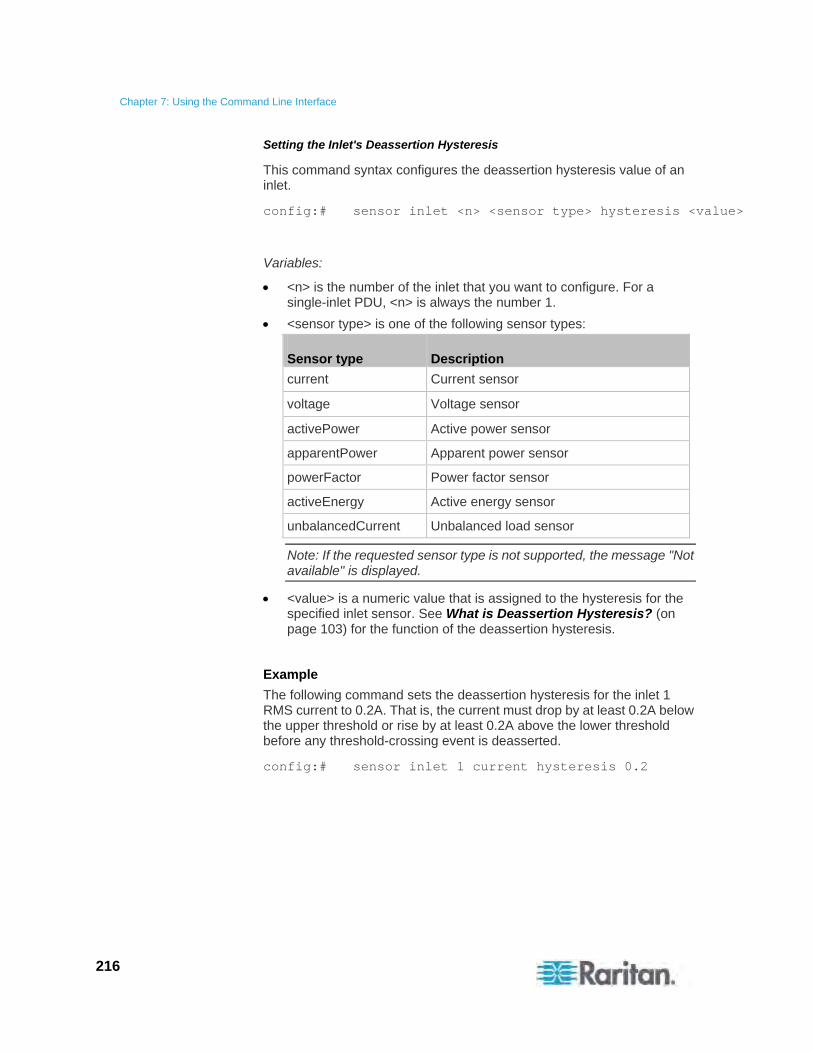
Chapter 7: Using the Command Line Interface
216
Setting the Inlet's Deassertion Hysteresis
This command syntax configures the deassertion hysteresis value of an inlet.
config:# sensor inlet <n> <sensor type> hysteresis <value>
Variables:
<n> is the number of the inlet that you want to configure. For a single-inlet PDU, <n> is always the number 1.
<sensor type> is one of the following sensor types:
Sensor type Description
current Current sensor
voltage Voltage sensor
activePower Active power sensor
apparentPower Apparent power sensor
powerFactor Power factor sensor
activeEnergy Active energy sensor
unbalancedCurrent Unbalanced load sensor
Note: If the requested sensor type is not supported, the message "Not available" is displayed.
<value> is a numeric value that is assigned to the hysteresis for the specified inlet sensor. See What is Deassertion Hysteresis? (on page 103) for the function of the deassertion hysteresis.
Example
The following command sets the deassertion hysteresis for the inlet 1 RMS current to 0.2A. That is, the current must drop by at least 0.2A below the upper threshold or rise by at least 0.2A above the lower threshold before any threshold-crossing event is deasserted.
config:# sensor inlet 1 current hysteresis 0.2
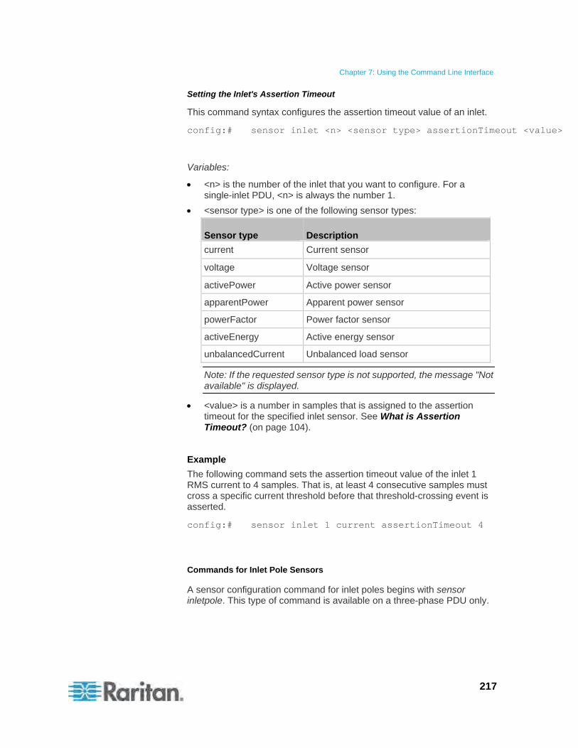
Chapter 7: Using the Command Line Interface
217
Setting the Inlet's Assertion Timeout
This command syntax configures the assertion timeout value of an inlet.
config:# sensor inlet <n> <sensor type> assertionTimeout <value>
Variables:
<n> is the number of the inlet that you want to configure. For a single-inlet PDU, <n> is always the number 1.
<sensor type> is one of the following sensor types:
Sensor type Description
current Current sensor
voltage Voltage sensor
activePower Active power sensor
apparentPower Apparent power sensor
powerFactor Power factor sensor
activeEnergy Active energy sensor
unbalancedCurrent Unbalanced load sensor
Note: If the requested sensor type is not supported, the message "Not available" is displayed.
<value> is a number in samples that is assigned to the assertion timeout for the specified inlet sensor. See What is Assertion Timeout? (on page 104).
Example
The following command sets the assertion timeout value of the inlet 1 RMS current to 4 samples. That is, at least 4 consecutive samples must cross a specific current threshold before that threshold-crossing event is asserted.
config:# sensor inlet 1 current assertionTimeout 4
Commands for Inlet Pole Sensors
A sensor configuration command for inlet poles begins with sensor inletpole. This type of command is available on a three-phase PDU only.
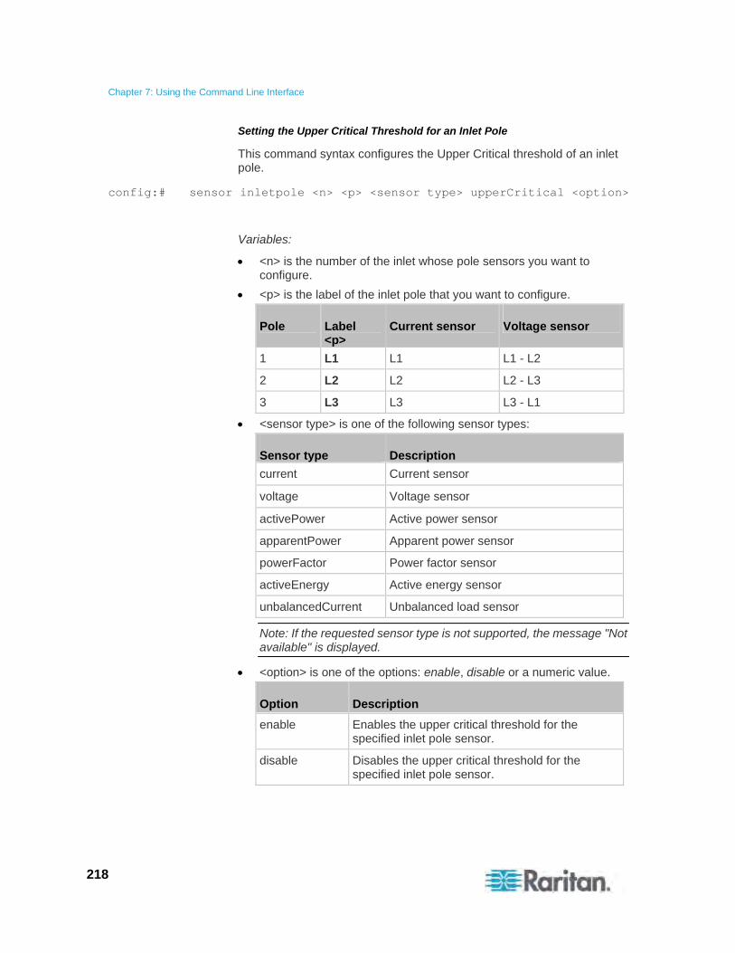
Chapter 7: Using the Command Line Interface
218
Setting the Upper Critical Threshold for an Inlet Pole
This command syntax configures the Upper Critical threshold of an inlet pole.
config:# sensor inletpole <n> <p> <sensor type> upperCritical <option>
Variables:
<n> is the number of the inlet whose pole sensors you want to configure.
<p> is the label of the inlet pole that you want to configure.
Pole Label <p>
Current sensor Voltage sensor
1 L1 L1 L1 - L2
2 L2 L2 L2 - L3
3 L3 L3 L3 - L1
<sensor type> is one of the following sensor types:
Sensor type Description
current Current sensor
voltage Voltage sensor
activePower Active power sensor
apparentPower Apparent power sensor
powerFactor Power factor sensor
activeEnergy Active energy sensor
unbalancedCurrent Unbalanced load sensor
Note: If the requested sensor type is not supported, the message "Not available" is displayed.
<option> is one of the options: enable, disable or a numeric value.
Option Description
enable Enables the upper critical threshold for the specified inlet pole sensor.
disable Disables the upper critical threshold for the specified inlet pole sensor.
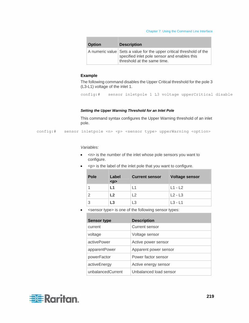
Chapter 7: Using the Command Line Interface
219
Option Description
A numeric value Sets a value for the upper critical threshold of the specified inlet pole sensor and enables this threshold at the same time.
Example
The following command disables the Upper Critical threshold for the pole 3 (L3-L1) voltage of the inlet 1.
config:# sensor inletpole 1 L3 voltage upperCritical disable
Setting the Upper Warning Threshold for an Inlet Pole
This command syntax configures the Upper Warning threshold of an inlet pole.
config:# sensor inletpole <n> <p> <sensor type> upperWarning <option>
Variables:
<n> is the number of the inlet whose pole sensors you want to configure.
<p> is the label of the inlet pole that you want to configure.
Pole Label <p>
Current sensor Voltage sensor
1 L1 L1 L1 - L2
2 L2 L2 L2 - L3
3 L3 L3 L3 - L1
<sensor type> is one of the following sensor types:
Sensor type Description
current Current sensor
voltage Voltage sensor
activePower Active power sensor
apparentPower Apparent power sensor
powerFactor Power factor sensor
activeEnergy Active energy sensor
unbalancedCurrent Unbalanced load sensor
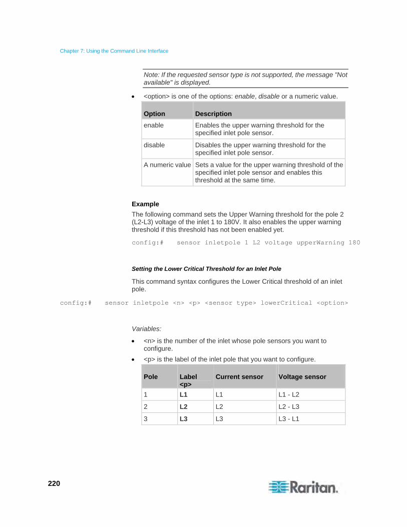
Chapter 7: Using the Command Line Interface
220
Note: If the requested sensor type is not supported, the message "Not available" is displayed.
<option> is one of the options: enable, disable or a numeric value.
Option Description
enable Enables the upper warning threshold for the specified inlet pole sensor.
disable Disables the upper warning threshold for the specified inlet pole sensor.
A numeric value Sets a value for the upper warning threshold of the specified inlet pole sensor and enables this threshold at the same time.
Example
The following command sets the Upper Warning threshold for the pole 2 (L2-L3) voltage of the inlet 1 to 180V. It also enables the upper warning threshold if this threshold has not been enabled yet.
config:# sensor inletpole 1 L2 voltage upperWarning 180
Setting the Lower Critical Threshold for an Inlet Pole
This command syntax configures the Lower Critical threshold of an inlet pole.
config:# sensor inletpole <n> <p> <sensor type> lowerCritical <option>
Variables:
<n> is the number of the inlet whose pole sensors you want to configure.
<p> is the label of the inlet pole that you want to configure.
Pole Label <p>
Current sensor Voltage sensor
1 L1 L1 L1 - L2
2 L2 L2 L2 - L3
3 L3 L3 L3 - L1
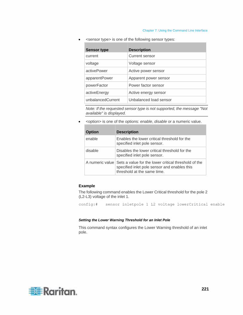
Chapter 7: Using the Command Line Interface
221
<sensor type> is one of the following sensor types:
Sensor type Description
current Current sensor
voltage Voltage sensor
activePower Active power sensor
apparentPower Apparent power sensor
powerFactor Power factor sensor
activeEnergy Active energy sensor
unbalancedCurrent Unbalanced load sensor
Note: If the requested sensor type is not supported, the message "Not available" is displayed.
<option> is one of the options: enable, disable or a numeric value.
Option Description
enable Enables the lower critical threshold for the specified inlet pole sensor.
disable Disables the lower critical threshold for the specified inlet pole sensor.
A numeric value Sets a value for the lower critical threshold of the specified inlet pole sensor and enables this threshold at the same time.
Example
The following command enables the Lower Critical threshold for the pole 2 (L2-L3) voltage of the inlet 1.
config:# sensor inletpole 1 L2 voltage lowerCritical enable
Setting the Lower Warning Threshold for an Inlet Pole
This command syntax configures the Lower Warning threshold of an inlet pole.
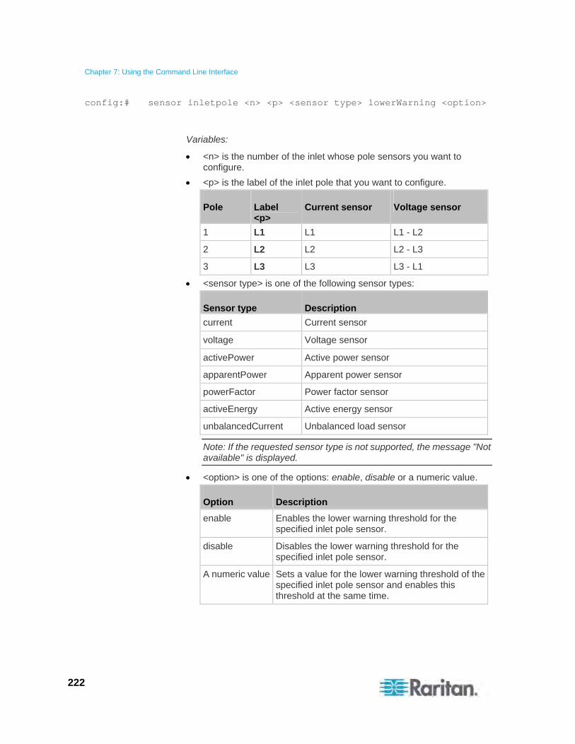
Chapter 7: Using the Command Line Interface
222
config:# sensor inletpole <n> <p> <sensor type> lowerWarning <option>
Variables:
<n> is the number of the inlet whose pole sensors you want to configure.
<p> is the label of the inlet pole that you want to configure.
Pole Label <p>
Current sensor Voltage sensor
1 L1 L1 L1 - L2
2 L2 L2 L2 - L3
3 L3 L3 L3 - L1
<sensor type> is one of the following sensor types:
Sensor type Description
current Current sensor
voltage Voltage sensor
activePower Active power sensor
apparentPower Apparent power sensor
powerFactor Power factor sensor
activeEnergy Active energy sensor
unbalancedCurrent Unbalanced load sensor
Note: If the requested sensor type is not supported, the message "Not available" is displayed.
<option> is one of the options: enable, disable or a numeric value.
Option Description
enable Enables the lower warning threshold for the specified inlet pole sensor.
disable Disables the lower warning threshold for the specified inlet pole sensor.
A numeric value Sets a value for the lower warning threshold of the specified inlet pole sensor and enables this threshold at the same time.
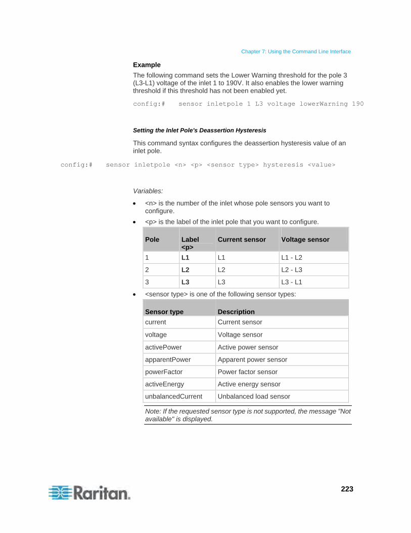
Chapter 7: Using the Command Line Interface
223
Example
The following command sets the Lower Warning threshold for the pole 3 (L3-L1) voltage of the inlet 1 to 190V. It also enables the lower warning threshold if this threshold has not been enabled yet.
config:# sensor inletpole 1 L3 voltage lowerWarning 190
Setting the Inlet Pole's Deassertion Hysteresis
This command syntax configures the deassertion hysteresis value of an inlet pole.
config:# sensor inletpole <n> <p> <sensor type> hysteresis <value>
Variables:
<n> is the number of the inlet whose pole sensors you want to configure.
<p> is the label of the inlet pole that you want to configure.
Pole Label <p>
Current sensor Voltage sensor
1 L1 L1 L1 - L2
2 L2 L2 L2 - L3
3 L3 L3 L3 - L1
<sensor type> is one of the following sensor types:
Sensor type Description
current Current sensor
voltage Voltage sensor
activePower Active power sensor
apparentPower Apparent power sensor
powerFactor Power factor sensor
activeEnergy Active energy sensor
unbalancedCurrent Unbalanced load sensor
Note: If the requested sensor type is not supported, the message "Not available" is displayed.
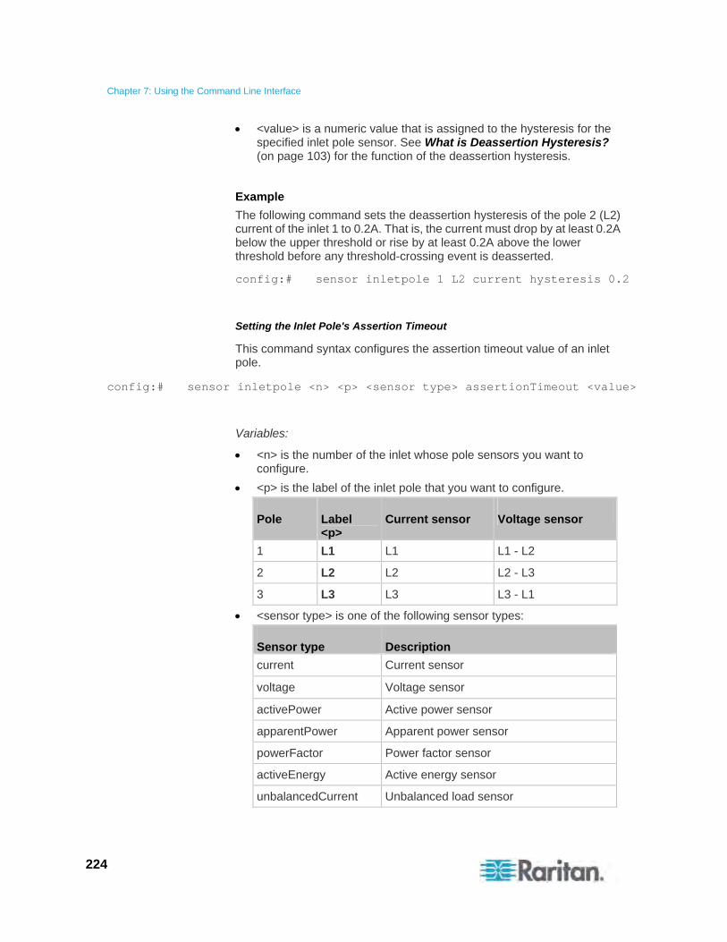
Chapter 7: Using the Command Line Interface
224
<value> is a numeric value that is assigned to the hysteresis for the specified inlet pole sensor. See What is Deassertion Hysteresis? (on page 103) for the function of the deassertion hysteresis.
Example
The following command sets the deassertion hysteresis of the pole 2 (L2) current of the inlet 1 to 0.2A. That is, the current must drop by at least 0.2A below the upper threshold or rise by at least 0.2A above the lower threshold before any threshold-crossing event is deasserted.
config:# sensor inletpole 1 L2 current hysteresis 0.2
Setting the Inlet Pole's Assertion Timeout
This command syntax configures the assertion timeout value of an inlet pole.
config:# sensor inletpole <n> <p> <sensor type> assertionTimeout <value>
Variables:
<n> is the number of the inlet whose pole sensors you want to configure.
<p> is the label of the inlet pole that you want to configure.
Pole Label <p>
Current sensor Voltage sensor
1 L1 L1 L1 - L2
2 L2 L2 L2 - L3
3 L3 L3 L3 - L1
<sensor type> is one of the following sensor types:
Sensor type Description
current Current sensor
voltage Voltage sensor
activePower Active power sensor
apparentPower Apparent power sensor
powerFactor Power factor sensor
activeEnergy Active energy sensor
unbalancedCurrent Unbalanced load sensor

Chapter 7: Using the Command Line Interface
225
Note: If the requested sensor type is not supported, the message "Not available" is displayed.
<value> is a number in samples that is assigned to the assertion timeout for the specified inlet pole sensor. See What is Assertion Timeout? (on page 104).
Example
The following command sets the assertion timeout value of the pole 2 (L2) current of the inlet 1 to 4 samples. That is, at least 4 consecutive samples must cross a specific current threshold before that threshold-crossing event is asserted.
config:# sensor inletpole 1 L2 current assertionTimeout 4
Commands for Environmental Sensors
A sensor threshold configuration command for environmental sensors begins with sensor externalsensor.
Setting the Sensor's Upper Critical Threshold
This command syntax configures the Upper Critical threshold of a numeric environmental sensor.
config:# sensor externalsensor <n> <sensor type> upperCritical <option>
Variables:
<n> is the ID number of the environmental sensor that you want to configure. The ID number is assigned and shown in the Raritan PXE web interface. It is an integer between 1 and 16.
<sensor type> is one of these sensor types: temperature, humidity, airPressure or air Flow.
Note: If the specified sensor type does not match the type of the specified environmental sensor, this error message appears: "Specified sensor type 'XXX' does not match the sensor's type (<sensortype>)," where XXX is the specified sensor type, and <sensortype> is the correct sensor type.

Chapter 7: Using the Command Line Interface
226
<option> is one of the options: enable, disable or a numeric value.
Option Description
enable Enables the upper critical threshold for the specified environmental sensor.
disable Disables the upper critical threshold for the specified environmental sensor.
A numeric value Sets a value for the upper critical threshold of the specified environmental sensor and enables this threshold at the same time.
Example
The following command sets the Upper Critical threshold of the environmental "temperature" sensor with the ID number 2 to 40 degrees Celsius. It also enables the upper critical threshold if this threshold has not been enabled yet.
config:# sensor externalsensor 2 temperature upperCritical 40
Setting the Sensor's Upper Warning Threshold
This command syntax configures the Upper Warning threshold of a numeric environmental sensor.
config:# sensor externalsensor <n> <sensor type> upperWarning <option>
Variables:
<n> is the ID number of the environmental sensor that you want to configure. The ID number is assigned and shown in the Raritan PXE web interface. It is an integer between 1 and 16.
<sensor type> is one of these sensor types: temperature, humidity, airPressure or air Flow.
Note: If the specified sensor type does not match the type of the specified environmental sensor, this error message appears: "Specified sensor type 'XXX' does not match the sensor's type (<sensortype>)," where XXX is the specified sensor type, and <sensortype> is the correct sensor type.
<option> is one of the options: enable, disable or a numeric value.
Option Description
enable Enables the upper warning threshold for the specified environmental sensor.
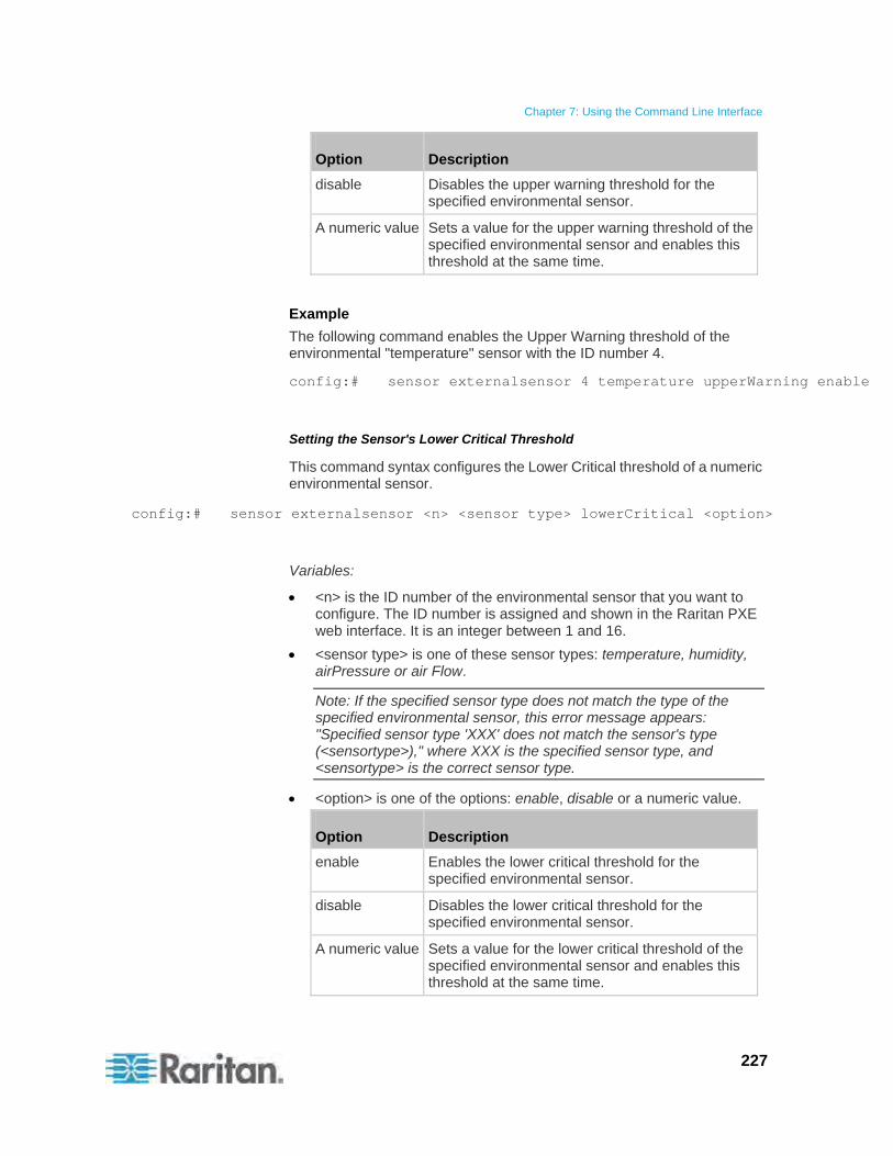
Chapter 7: Using the Command Line Interface
227
Option Description
disable Disables the upper warning threshold for the specified environmental sensor.
A numeric value Sets a value for the upper warning threshold of the specified environmental sensor and enables this threshold at the same time.
Example
The following command enables the Upper Warning threshold of the environmental "temperature" sensor with the ID number 4.
config:# sensor externalsensor 4 temperature upperWarning enable
Setting the Sensor's Lower Critical Threshold
This command syntax configures the Lower Critical threshold of a numeric environmental sensor.
config:# sensor externalsensor <n> <sensor type> lowerCritical <option>
Variables:
<n> is the ID number of the environmental sensor that you want to configure. The ID number is assigned and shown in the Raritan PXE web interface. It is an integer between 1 and 16.
<sensor type> is one of these sensor types: temperature, humidity, airPressure or air Flow.
Note: If the specified sensor type does not match the type of the specified environmental sensor, this error message appears: "Specified sensor type 'XXX' does not match the sensor's type (<sensortype>)," where XXX is the specified sensor type, and <sensortype> is the correct sensor type.
<option> is one of the options: enable, disable or a numeric value.
Option Description
enable Enables the lower critical threshold for the specified environmental sensor.
disable Disables the lower critical threshold for the specified environmental sensor.
A numeric value Sets a value for the lower critical threshold of the specified environmental sensor and enables this threshold at the same time.
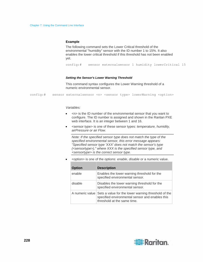
Chapter 7: Using the Command Line Interface
228
Example
The following command sets the Lower Critical threshold of the environmental "humidity" sensor with the ID number 1 to 15%. It also enables the lower critical threshold if this threshold has not been enabled yet.
config:# sensor externalsensor 1 humidity lowerCritical 15
Setting the Sensor's Lower Warning Threshold
This command syntax configures the Lower Warning threshold of a numeric environmental sensor.
config:# sensor externalsensor <n> <sensor type> lowerWarning <option>
Variables:
<n> is the ID number of the environmental sensor that you want to configure. The ID number is assigned and shown in the Raritan PXE web interface. It is an integer between 1 and 16.
<sensor type> is one of these sensor types: temperature, humidity, airPressure or air Flow.
Note: If the specified sensor type does not match the type of the specified environmental sensor, this error message appears: "Specified sensor type 'XXX' does not match the sensor's type (<sensortype>)," where XXX is the specified sensor type, and <sensortype> is the correct sensor type.
<option> is one of the options: enable, disable or a numeric value.
Option Description
enable Enables the lower warning threshold for the specified environmental sensor.
disable Disables the lower warning threshold for the specified environmental sensor.
A numeric value Sets a value for the lower warning threshold of the specified environmental sensor and enables this threshold at the same time.
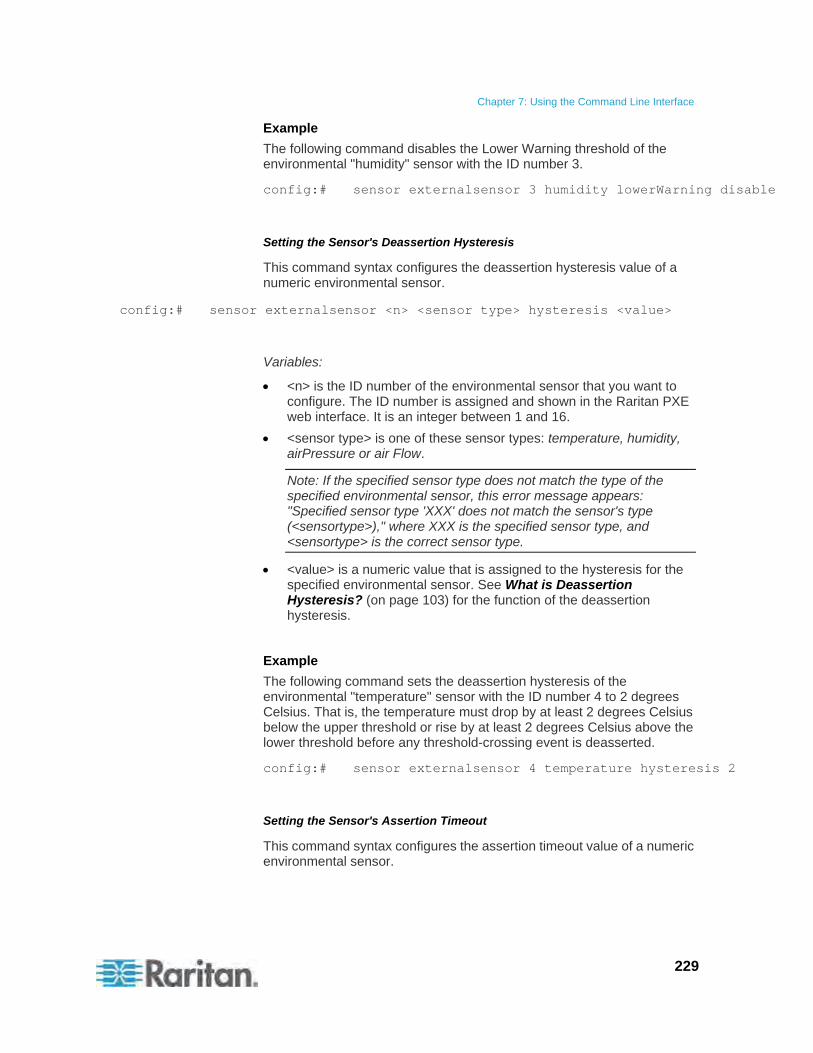
Chapter 7: Using the Command Line Interface
229
Example
The following command disables the Lower Warning threshold of the environmental "humidity" sensor with the ID number 3.
config:# sensor externalsensor 3 humidity lowerWarning disable
Setting the Sensor's Deassertion Hysteresis
This command syntax configures the deassertion hysteresis value of a numeric environmental sensor.
config:# sensor externalsensor <n> <sensor type> hysteresis <value>
Variables:
<n> is the ID number of the environmental sensor that you want to configure. The ID number is assigned and shown in the Raritan PXE web interface. It is an integer between 1 and 16.
<sensor type> is one of these sensor types: temperature, humidity, airPressure or air Flow.
Note: If the specified sensor type does not match the type of the specified environmental sensor, this error message appears: "Specified sensor type 'XXX' does not match the sensor's type (<sensortype>)," where XXX is the specified sensor type, and <sensortype> is the correct sensor type.
<value> is a numeric value that is assigned to the hysteresis for the specified environmental sensor. See What is Deassertion Hysteresis? (on page 103) for the function of the deassertion hysteresis.
Example
The following command sets the deassertion hysteresis of the environmental "temperature" sensor with the ID number 4 to 2 degrees Celsius. That is, the temperature must drop by at least 2 degrees Celsius below the upper threshold or rise by at least 2 degrees Celsius above the lower threshold before any threshold-crossing event is deasserted.
config:# sensor externalsensor 4 temperature hysteresis 2
Setting the Sensor's Assertion Timeout
This command syntax configures the assertion timeout value of a numeric environmental sensor.
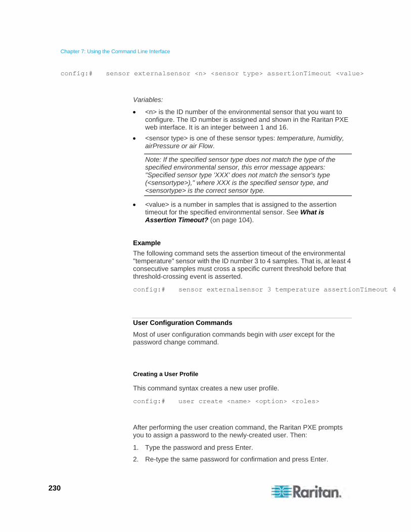
Chapter 7: Using the Command Line Interface
230
config:# sensor externalsensor <n> <sensor type> assertionTimeout <value>
Variables:
<n> is the ID number of the environmental sensor that you want to configure. The ID number is assigned and shown in the Raritan PXE web interface. It is an integer between 1 and 16.
<sensor type> is one of these sensor types: temperature, humidity, airPressure or air Flow.
Note: If the specified sensor type does not match the type of the specified environmental sensor, this error message appears: "Specified sensor type 'XXX' does not match the sensor's type (<sensortype>)," where XXX is the specified sensor type, and <sensortype> is the correct sensor type.
<value> is a number in samples that is assigned to the assertion timeout for the specified environmental sensor. See What is Assertion Timeout? (on page 104).
Example
The following command sets the assertion timeout of the environmental "temperature" sensor with the ID number 3 to 4 samples. That is, at least 4 consecutive samples must cross a specific current threshold before that threshold-crossing event is asserted.
config:# sensor externalsensor 3 temperature assertionTimeout 4
User Configuration Commands
Most of user configuration commands begin with user except for the password change command.
Creating a User Profile
This command syntax creates a new user profile.
config:# user create <name> <option> <roles>
After performing the user creation command, the Raritan PXE prompts you to assign a password to the newly-created user. Then:
1. Type the password and press Enter.
2. Re-type the same password for confirmation and press Enter.
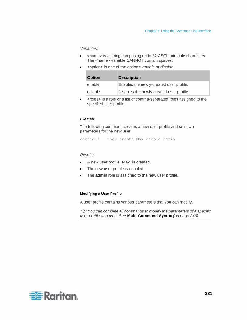
Chapter 7: Using the Command Line Interface
231
Variables:
<name> is a string comprising up to 32 ASCII printable characters. The <name> variable CANNOT contain spaces.
<option> is one of the options: enable or disable.
Option Description
enable Enables the newly-created user profile.
disable Disables the newly-created user profile.
<roles> is a role or a list of comma-separated roles assigned to the specified user profile.
Example
The following command creates a new user profile and sets two parameters for the new user.
config:# user create May enable admin
Results:
A new user profile "May" is created.
The new user profile is enabled.
The admin role is assigned to the new user profile.
Modifying a User Profile
A user profile contains various parameters that you can modify.
Tip: You can combine all commands to modify the parameters of a specific user profile at a time. See Multi-Command Syntax (on page 249).

Chapter 7: Using the Command Line Interface
232
Changing a User's Password
This command syntax allows you to change an existing user's password if you have the Administrator Privileges.
config:# user modify <name> password
After performing the above command, Raritan PXE prompts you to enter a new password. Then:
1. Type a new password and press Enter.
2. Re-type the new password for confirmation and press Enter.
Variables:
<name> is the name of the user whose settings you want to change.
Example
The following procedure illustrates how to change the password of the user "May."
1. Verify that you have entered the configuration mode. See Entering the Configuration Mode (on page 165).
2. Type the following command to change the password for the user profile "May."
config:# user modify May password
3. Type a new password when prompted, and press Enter.
4. Type the same new password and press Enter.
5. If the password change is completed successfully, the config:# prompt appears.
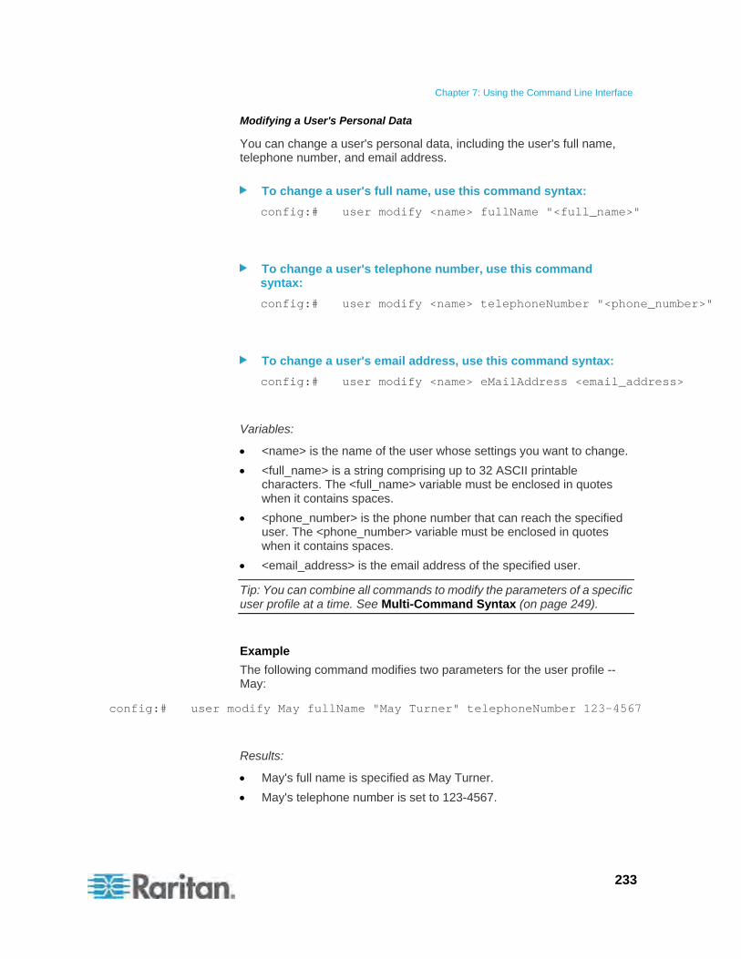
Chapter 7: Using the Command Line Interface
233
Modifying a User's Personal Data
You can change a user's personal data, including the user's full name, telephone number, and email address.
To change a user's full name, use this command syntax:
config:# user modify <name> fullName "<full_name>"
To change a user's telephone number, use this command syntax:
config:# user modify <name> telephoneNumber "<phone_number>"
To change a user's email address, use this command syntax:
config:# user modify <name> eMailAddress <email_address>
Variables:
<name> is the name of the user whose settings you want to change.
<full_name> is a string comprising up to 32 ASCII printable characters. The <full_name> variable must be enclosed in quotes when it contains spaces.
<phone_number> is the phone number that can reach the specified user. The <phone_number> variable must be enclosed in quotes when it contains spaces.
<email_address> is the email address of the specified user.
Tip: You can combine all commands to modify the parameters of a specific user profile at a time. See Multi-Command Syntax (on page 249).
Example
The following command modifies two parameters for the user profile -- May:
config:# user modify May fullName "May Turner" telephoneNumber 123-4567
Results:
May's full name is specified as May Turner.
May's telephone number is set to 123-4567.

Chapter 7: Using the Command Line Interface
234
Enabling or Disabling a User Profile
This command syntax enables or disables a user profile. A user can log in to the Raritan PXE device only after that user's user profile is enabled.
config:# user modify <name> enabled <option>
Variables:
<name> is the name of the user whose settings you want to change.
<option> is one of the options: true or false.
Option Description
true Enables the specified user profile.
false Disables the specified user profile.
Example
The following command enables the user profile -- May.
config:# user modify May enabled true
Forcing a Password Change
This command syntax determines whether the password change is forced when a user logs in to the specified user profile next time.
config:# user modify <name> forcePasswordChangeOnNextLogin <option>
Variables:
<name> is the name of the user whose settings you want to change.
<option> is one of the options: true or false.
Option Description
true A password change is forced on the user's next login.
false No password change is forced on the user's next login.
Example
The following command enforces a password change on May's next login.
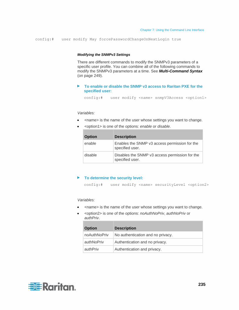
Chapter 7: Using the Command Line Interface
235
config:# user modify May forcePasswordChangeOnNextLogin true
Modifying the SNMPv3 Settings
There are different commands to modify the SNMPv3 parameters of a specific user profile. You can combine all of the following commands to modify the SNMPv3 parameters at a time. See Multi-Command Syntax (on page 249).
To enable or disable the SNMP v3 access to Raritan PXE for the specified user:
config:# user modify <name> snmpV3Access <option1>
Variables:
<name> is the name of the user whose settings you want to change.
<option1> is one of the options: enable or disable.
Option Description
enable Enables the SNMP v3 access permission for the specified user.
disable Disables the SNMP v3 access permission for the specified user.
To determine the security level:
config:# user modify <name> securityLevel <option2>
Variables:
<name> is the name of the user whose settings you want to change.
<option2> is one of the options: noAuthNoPriv, authNoPriv or authPriv.
Option Description
noAuthNoPriv No authentication and no privacy.
authNoPriv Authentication and no privacy.
authPriv Authentication and privacy.

Chapter 7: Using the Command Line Interface
236
To determine whether the authentication passphrase is identical to the password:
config:# user modify <name> userPasswordAsAuthenticationPassPhrase <option3>
Variables:
<name> is the name of the user whose settings you want to change.
<option3> is one of the options: true or false.
Option Description
true Authentication passphrase is identical to the password.
false Authentication passphrase is different from the password.
To determine the authentication passphrase:
config:# user modify <name> authenticationPassPhrase <authentication_passphrase>
Variables:
<name> is the name of the user whose settings you want to change.
<authentication_passphrase> is a string used as an authentication passphrase, comprising up to 32 ASCII printable characters.
To determine whether the privacy passphrase is identical to the authentication passphrase:
config:# user modify <name> useAuthenticationPassPhraseAsPrivacyPassPhrase <option4>
Variables:
<name> is the name of the user whose settings you want to change.
<option4> is one of the options: true or false.
Option Description
true Privacy passphrase is identical to the authentication passphrase.
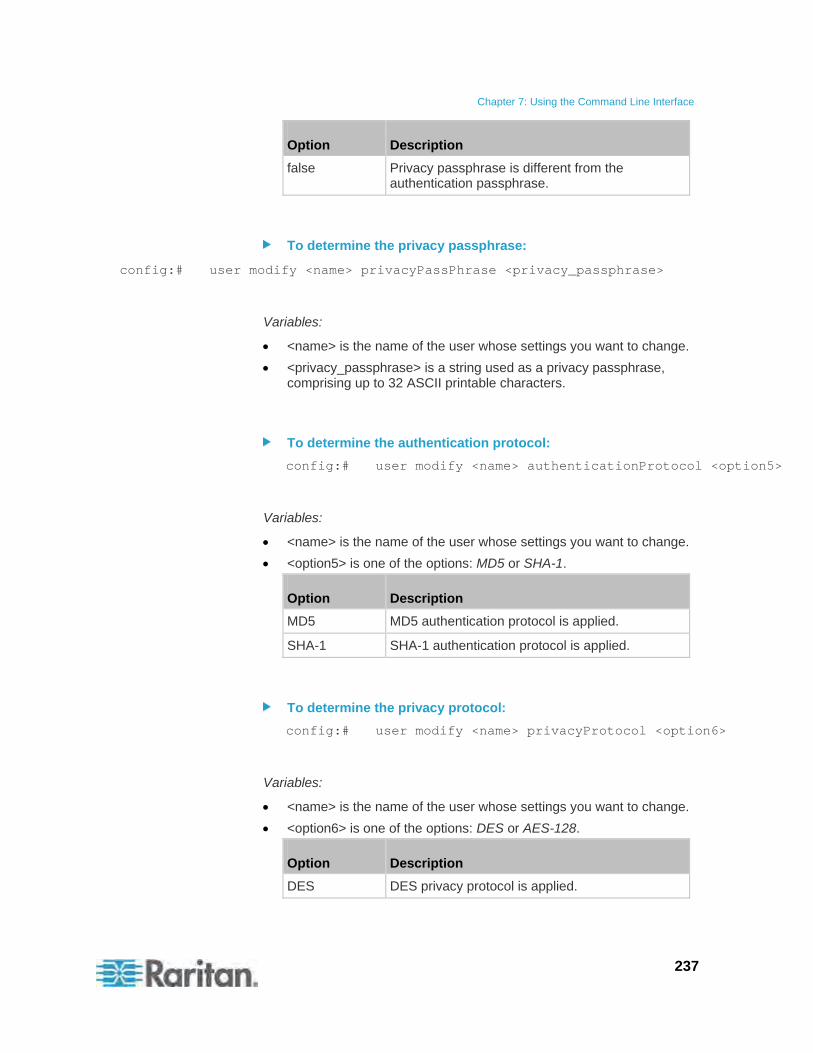
Chapter 7: Using the Command Line Interface
237
Option Description
false Privacy passphrase is different from the authentication passphrase.
To determine the privacy passphrase:
config:# user modify <name> privacyPassPhrase <privacy_passphrase>
Variables:
<name> is the name of the user whose settings you want to change.
<privacy_passphrase> is a string used as a privacy passphrase, comprising up to 32 ASCII printable characters.
To determine the authentication protocol:
config:# user modify <name> authenticationProtocol <option5>
Variables:
<name> is the name of the user whose settings you want to change.
<option5> is one of the options: MD5 or SHA-1.
Option Description
MD5 MD5 authentication protocol is applied.
SHA-1 SHA-1 authentication protocol is applied.
To determine the privacy protocol:
config:# user modify <name> privacyProtocol <option6>
Variables:
<name> is the name of the user whose settings you want to change.
<option6> is one of the options: DES or AES-128.
Option Description
DES DES privacy protocol is applied.
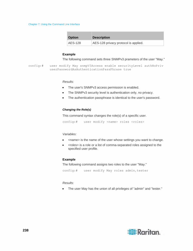
Chapter 7: Using the Command Line Interface
238
Option Description
AES-128 AES-128 privacy protocol is applied.
Example
The following command sets three SNMPv3 prameters of the user "May."
config:# user modify May snmpV3Access enable securityLevel authNoPriv userPasswordAsAuthenticationPassPhrase true
Results:
The user's SNMPv3 access permission is enabled.
The SNMPv3 security level is authentication only, no privacy.
The authentication passphrase is identical to the user's password.
Changing the Role(s)
This command syntax changes the role(s) of a specific user.
config:# user modify <name> roles <roles>
Variables:
<name> is the name of the user whose settings you want to change.
<roles> is a role or a list of comma-separated roles assigned to the specified user profile.
Example
The following command assigns two roles to the user "May."
config:# user modify May roles admin,tester
Results:
The user May has the union of all privileges of "admin" and "tester."
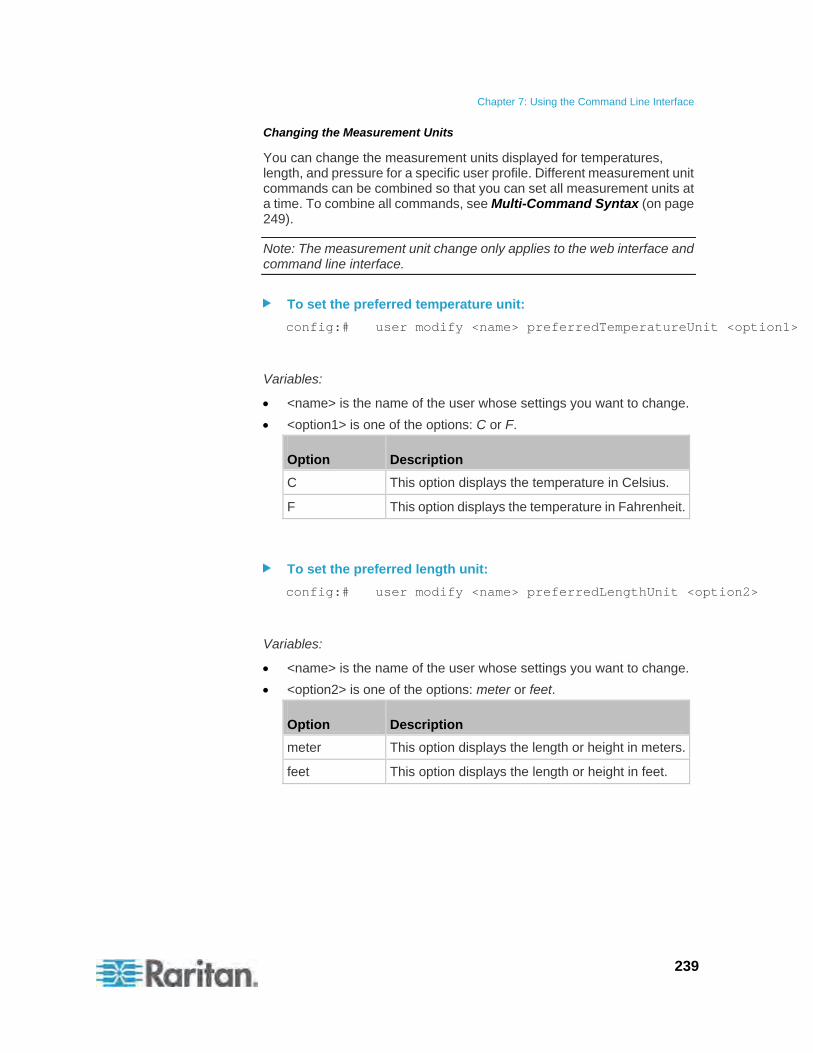
Chapter 7: Using the Command Line Interface
239
Changing the Measurement Units
You can change the measurement units displayed for temperatures, length, and pressure for a specific user profile. Different measurement unit commands can be combined so that you can set all measurement units at a time. To combine all commands, see Multi-Command Syntax (on page 249).
Note: The measurement unit change only applies to the web interface and command line interface.
To set the preferred temperature unit:
config:# user modify <name> preferredTemperatureUnit <option1>
Variables:
<name> is the name of the user whose settings you want to change.
<option1> is one of the options: C or F.
Option Description
C This option displays the temperature in Celsius.
F This option displays the temperature in Fahrenheit.
To set the preferred length unit:
config:# user modify <name> preferredLengthUnit <option2>
Variables:
<name> is the name of the user whose settings you want to change.
<option2> is one of the options: meter or feet.
Option Description
meter This option displays the length or height in meters.
feet This option displays the length or height in feet.
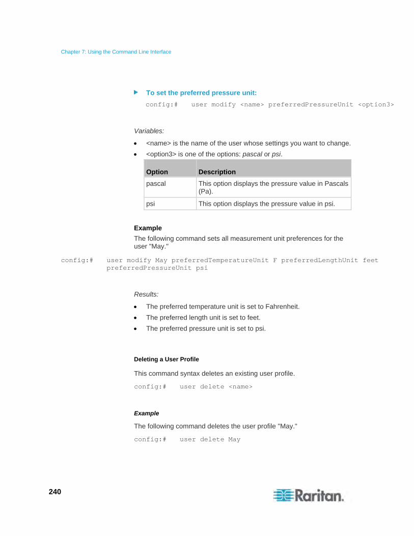
Chapter 7: Using the Command Line Interface
240
To set the preferred pressure unit:
config:# user modify <name> preferredPressureUnit <option3>
Variables:
<name> is the name of the user whose settings you want to change.
<option3> is one of the options: pascal or psi.
Option Description
pascal This option displays the pressure value in Pascals (Pa).
psi This option displays the pressure value in psi.
Example
The following command sets all measurement unit preferences for the user "May."
config:# user modify May preferredTemperatureUnit F preferredLengthUnit feet preferredPressureUnit psi
Results:
The preferred temperature unit is set to Fahrenheit.
The preferred length unit is set to feet.
The preferred pressure unit is set to psi.
Deleting a User Profile
This command syntax deletes an existing user profile.
config:# user delete <name>
Example
The following command deletes the user profile "May."
config:# user delete May

Chapter 7: Using the Command Line Interface
241
Changing Your Own Password
Every user can change their own password via this command syntax if they have the Change Own Password privilege. Note that this command does not begin with user.
config:# password
After performing this command, the Raritan PXE prompts you to enter both current and new passwords respectively.
Important: After the password is changed successfully, the new password is effective immediately no matter you type the command "apply" or not to save the changes.
Example
This procedure changes your own password:
1. Verify that you have entered the configuration mode. See Entering the Configuration Mode (on page 165).
2. Type the following command and press Enter.
config:# password
3. Type the existing password and press Enter when the following prompt appears.
Current password:
4. Type the new password and press Enter when the following prompt appears.
Enter new password:
5. Re-type the new password for confirmation and press Enter when the following prompt appears.
Re-type new password:
Role Configuration Commands
A role configuration command begins with role.
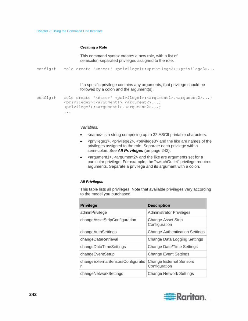
Chapter 7: Using the Command Line Interface
242
Creating a Role
This command syntax creates a new role, with a list of semicolon-separated privileges assigned to the role.
config:# role create "<name>" <privilege1>;<privilege2>;<privilege3>...
If a specific privilege contains any arguments, that privilege should be followed by a colon and the argument(s).
config:# role create "<name>" <privilege1>:<argument1>,<argument2>...; <privilege2>:<argument1>,<argument2>...; <privilege3>:<argument1>,<argument2>...; ...
Variables:
<name> is a string comprising up to 32 ASCII printable characters.
<privilege1>, <privilege2>, <privilege3> and the like are names of the privileges assigned to the role. Separate each privilege with a semi-colon. See All Privileges (on page 242).
<argument1>, <argument2> and the like are arguments set for a particular privilege. For example, the "switchOutlet" privilege requires arguments. Separate a privilege and its argument with a colon.
All Privileges
This table lists all privileges. Note that available privileges vary according to the model you purchased.
Privilege Description
adminPrivilege Administrator Privileges
changeAssetStripConfiguration Change Asset Strip Configuration
changeAuthSettings Change Authentication Settings
changeDataRetrieval Change Data Logging Settings
changeDataTimeSettings Change Date/Time Settings
changeEventSetup Change Event Settings
changeExternalSensorsConfiguration
Change External Sensors Configuration
changeNetworkSettings Change Network Settings
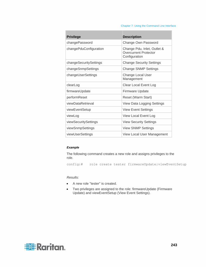
Chapter 7: Using the Command Line Interface
243
Privilege Description
changePassword Change Own Password
changePduConfiguration Change Pdu, Inlet, Outlet & Overcurrent Protector Configuration
changeSecuritySettings Change Security Settings
changeSnmpSettings Change SNMP Settings
changeUserSettings Change Local User Management
clearLog Clear Local Event Log
firmwareUpdate Firmware Update
performReset Reset (Warm Start)
viewDataRetrieval View Data Logging Settings
viewEventSetup View Event Settings
viewLog View Local Event Log
viewSecuritySettings View Security Settings
viewSnmpSettings View SNMP Settings
viewUserSettings View Local User Management
Example
The following command creates a new role and assigns privileges to the role.
config:# role create tester firmwareUpdate;viewEventSetup
Results:
A new role "tester" is created.
Two privileges are assigned to the role: firmwareUpdate (Firmware Update) and viewEventSetup (View Event Settings).
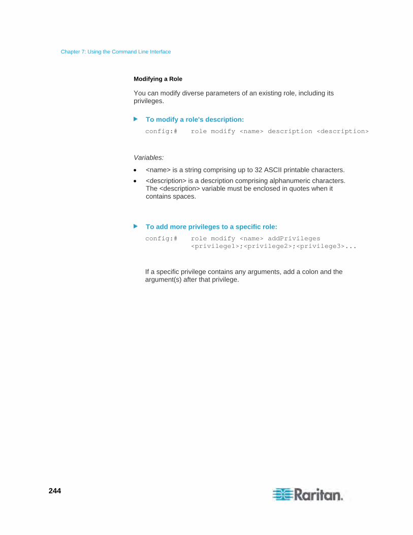
Chapter 7: Using the Command Line Interface
244
Modifying a Role
You can modify diverse parameters of an existing role, including its privileges.
To modify a role's description:
config:# role modify <name> description <description>
Variables:
<name> is a string comprising up to 32 ASCII printable characters.
<description> is a description comprising alphanumeric characters. The <description> variable must be enclosed in quotes when it contains spaces.
To add more privileges to a specific role:
config:# role modify <name> addPrivileges <privilege1>;<privilege2>;<privilege3>...
If a specific privilege contains any arguments, add a colon and the argument(s) after that privilege.
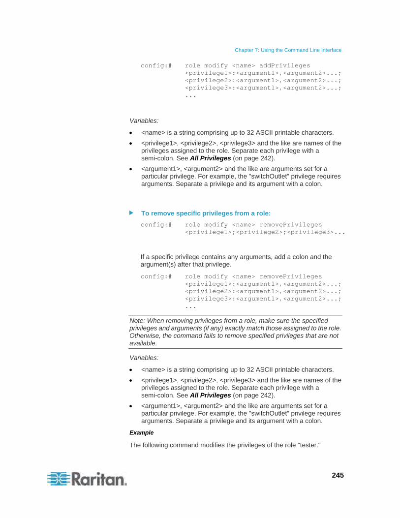
Chapter 7: Using the Command Line Interface
245
config:# role modify <name> addPrivileges <privilege1>:<argument1>,<argument2>...; <privilege2>:<argument1>,<argument2>...; <privilege3>:<argument1>,<argument2>...; ...
Variables:
<name> is a string comprising up to 32 ASCII printable characters.
<privilege1>, <privilege2>, <privilege3> and the like are names of the privileges assigned to the role. Separate each privilege with a semi-colon. See All Privileges (on page 242).
<argument1>, <argument2> and the like are arguments set for a particular privilege. For example, the "switchOutlet" privilege requires arguments. Separate a privilege and its argument with a colon.
To remove specific privileges from a role:
config:# role modify <name> removePrivileges <privilege1>;<privilege2>;<privilege3>...
If a specific privilege contains any arguments, add a colon and the argument(s) after that privilege.
config:# role modify <name> removePrivileges <privilege1>:<argument1>,<argument2>...; <privilege2>:<argument1>,<argument2>...; <privilege3>:<argument1>,<argument2>...; ...
Note: When removing privileges from a role, make sure the specified privileges and arguments (if any) exactly match those assigned to the role. Otherwise, the command fails to remove specified privileges that are not available.
Variables:
<name> is a string comprising up to 32 ASCII printable characters.
<privilege1>, <privilege2>, <privilege3> and the like are names of the privileges assigned to the role. Separate each privilege with a semi-colon. See All Privileges (on page 242).
<argument1>, <argument2> and the like are arguments set for a particular privilege. For example, the "switchOutlet" privilege requires arguments. Separate a privilege and its argument with a colon.
Example
The following command modifies the privileges of the role "tester."
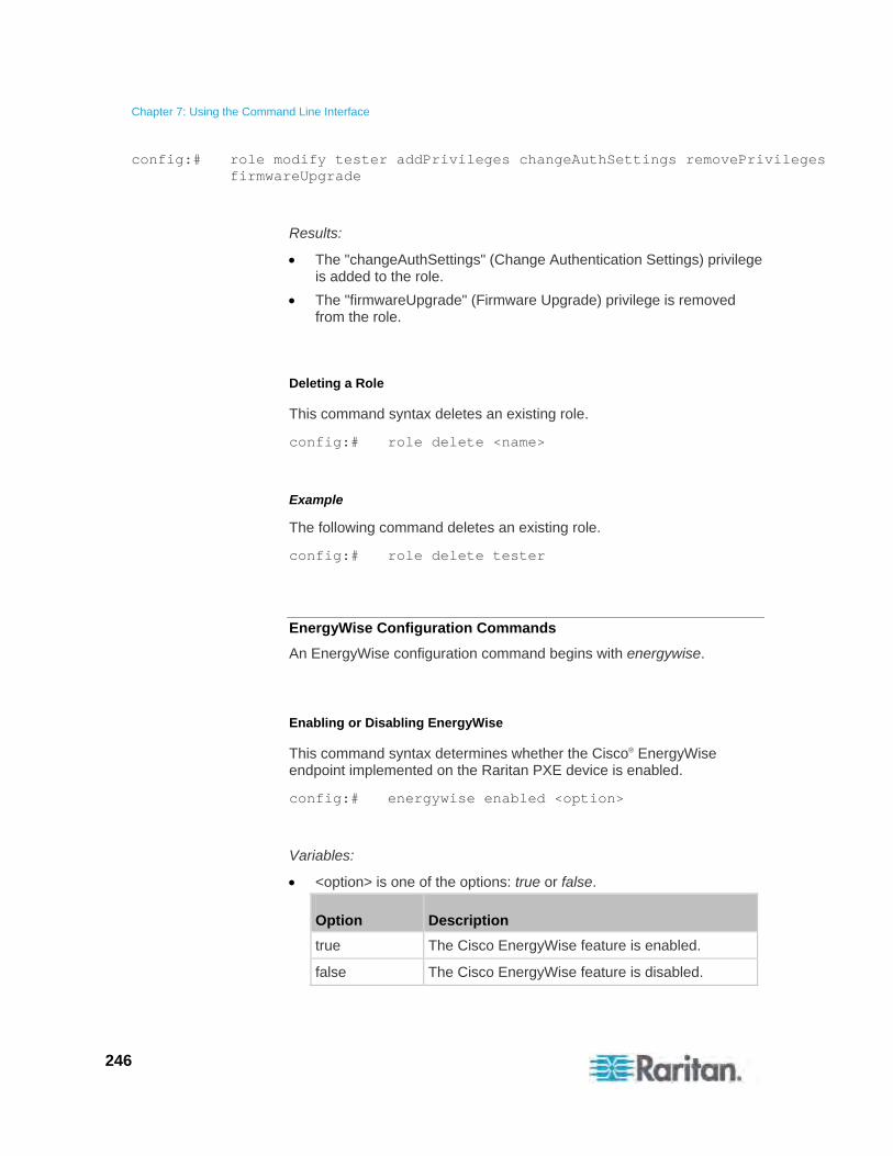
Chapter 7: Using the Command Line Interface
246
config:# role modify tester addPrivileges changeAuthSettings removePrivileges firmwareUpgrade
Results:
The "changeAuthSettings" (Change Authentication Settings) privilege is added to the role.
The "firmwareUpgrade" (Firmware Upgrade) privilege is removed from the role.
Deleting a Role
This command syntax deletes an existing role.
config:# role delete <name>
Example
The following command deletes an existing role.
config:# role delete tester
EnergyWise Configuration Commands
An EnergyWise configuration command begins with energywise.
Enabling or Disabling EnergyWise
This command syntax determines whether the Cisco® EnergyWise endpoint implemented on the Raritan PXE device is enabled.
config:# energywise enabled <option>
Variables:
<option> is one of the options: true or false.
Option Description
true The Cisco EnergyWise feature is enabled.
false The Cisco EnergyWise feature is disabled.

Chapter 7: Using the Command Line Interface
247
Example
The following command enables the Cisco® EnergyWise feature.
config:# energywise enabled true
Specifying the EnergyWise Domain
This command syntax specifies to which Cisco® EnergyWise domain the Raritan PXE device belongs.
config:# energywise domain <name>
Variables:
<name> is a string comprising up to 127 ASCII printable characters. Spaces and asterisks are NOT acceptable.
Example
The following command configures the Raritan PXE device to belong to the Cisco® EnergyWise domain named "helloDomain."
config:# energywise domain helloDomain
Specifying the EnergyWise Secret
This command syntax specifies the password (secret) to enter the Cisco® EnergyWise domain.
config:# energywise secret <password>
Variables:
<password> is a string comprising up to 127 ASCII printable characters. Spaces and asterisks are NOT acceptable.

Chapter 7: Using the Command Line Interface
248
Example
The following command specifies "password5233" as the Cisco® EnergyWise domain secret (password).
config:# energywise secret password5233
Changing the UDP Port
This command syntax specifies the UDP port for communications in the Cisco® EnergyWise domain.
config:# energywise port <port>
Variables:
<port> is the UDP port number ranging between 1 and 65535.
Example
The following command specifies 10288 as the UDP port for Cisco® EnergyWise.
config:# energywise port 10288
Setting the Polling Interval
This command syntax determines the polling interval at which the Cisco® EnergyWise domain queries the Raritan PXE device.
config:# energywise polling <timing>
Variables:
<timing> is an integer number in seconds. It ranges between 30 and 600 seconds.
Example
The following command determines the polling interval to query the Raritan PXE device is 300 seconds.
config:# energywise polling 300
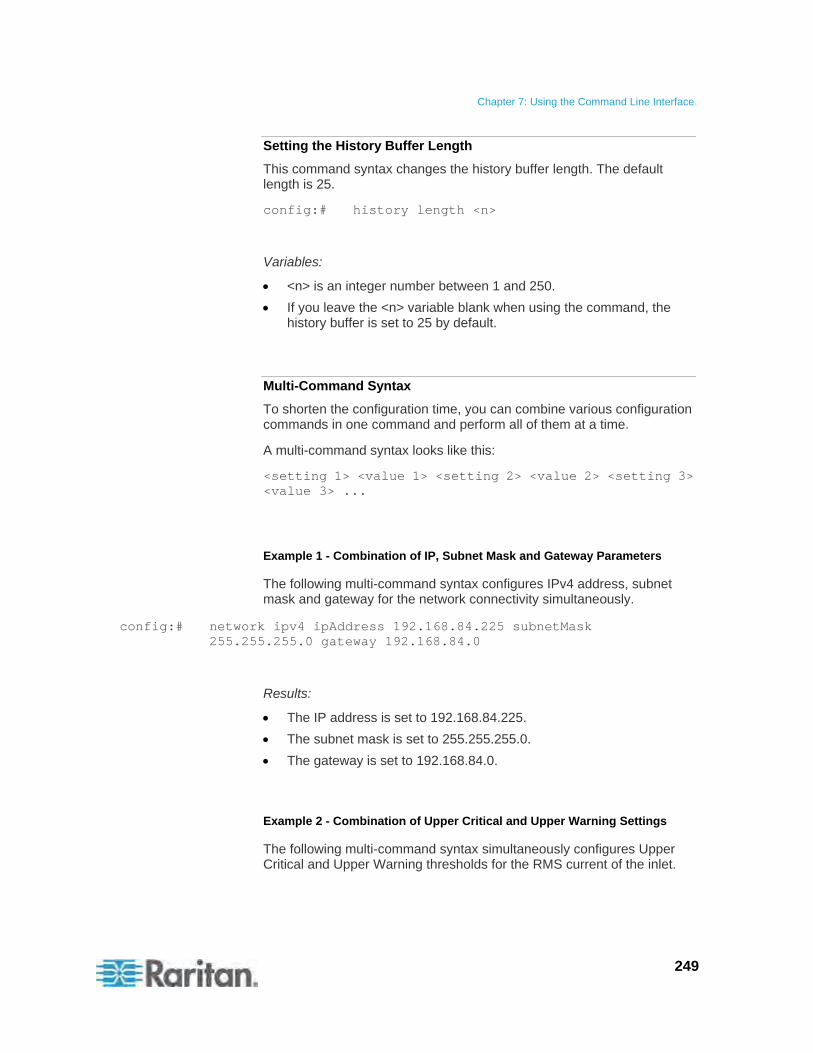
Chapter 7: Using the Command Line Interface
249
Setting the History Buffer Length
This command syntax changes the history buffer length. The default length is 25.
config:# history length <n>
Variables:
<n> is an integer number between 1 and 250.
If you leave the <n> variable blank when using the command, the history buffer is set to 25 by default.
Multi-Command Syntax
To shorten the configuration time, you can combine various configuration commands in one command and perform all of them at a time.
A multi-command syntax looks like this:
<setting 1> <value 1> <setting 2> <value 2> <setting 3> <value 3> ...
Example 1 - Combination of IP, Subnet Mask and Gateway Parameters
The following multi-command syntax configures IPv4 address, subnet mask and gateway for the network connectivity simultaneously.
config:# network ipv4 ipAddress 192.168.84.225 subnetMask 255.255.255.0 gateway 192.168.84.0
Results:
The IP address is set to 192.168.84.225.
The subnet mask is set to 255.255.255.0.
The gateway is set to 192.168.84.0.
Example 2 - Combination of Upper Critical and Upper Warning Settings
The following multi-command syntax simultaneously configures Upper Critical and Upper Warning thresholds for the RMS current of the inlet.
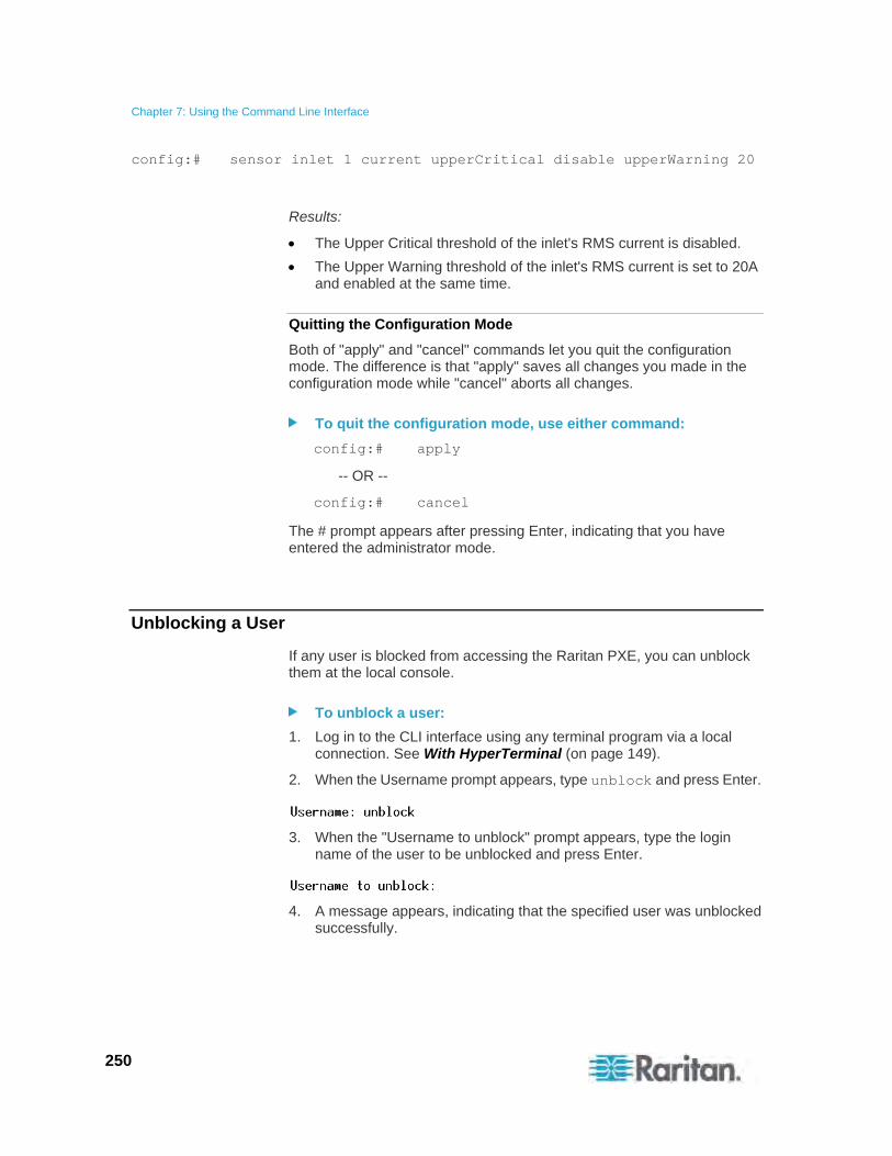
Chapter 7: Using the Command Line Interface
250
config:# sensor inlet 1 current upperCritical disable upperWarning 20
Results:
The Upper Critical threshold of the inlet's RMS current is disabled.
The Upper Warning threshold of the inlet's RMS current is set to 20A and enabled at the same time.
Quitting the Configuration Mode
Both of "apply" and "cancel" commands let you quit the configuration mode. The difference is that "apply" saves all changes you made in the configuration mode while "cancel" aborts all changes.
To quit the configuration mode, use either command:
config:# apply
-- OR --
config:# cancel
The # prompt appears after pressing Enter, indicating that you have entered the administrator mode.
Unblocking a User
If any user is blocked from accessing the Raritan PXE, you can unblock them at the local console.
To unblock a user:
1. Log in to the CLI interface using any terminal program via a local connection. See With HyperTerminal (on page 149).
2. When the Username prompt appears, type unblock and press Enter.
3. When the "Username to unblock" prompt appears, type the login name of the user to be unblocked and press Enter.
4. A message appears, indicating that the specified user was unblocked successfully.
Chapter 7: Using the Command Line Interface
251
Resetting the Raritan PXE
You can reset the Raritan PXE device to factory defaults or simply restart it using the CLI commands.
Restarting the PDU
This command restarts the Raritan PXE device. It is not a factory default reset.
To restart the Raritan PXE device:
1. Ensure you have entered the administrator mode and the # prompt is displayed.
2. Type either of the following commands to restart the Raritan PXE device.
# reset unit
-- OR --
# reset unit /y
3. If you entered the command without "/y" in Step 2, a message appears prompting you to confirm the operation. Type y to confirm the reset.
4. Wait until the Username prompt appears, indicating the reset is complete.
Resetting to Factory Defaults
This command restores all settings of the Raritan PXE device to factory defaults.
To reset Raritan PXE settings, use either command:
# reset factorydefaults
-- OR --
# reset factorydefaults /y
See Using the CLI Command (on page 263) for more information.
Network Troubleshooting
The Raritan PXE provides 4 diagnostic commands for troubleshooting network problems: nslookup, netstat, ping, and traceroute. The diagnostic commands function as corresponding Linux commands and can get corresponding Linux outputs.
Chapter 7: Using the Command Line Interface
252
Entering the Diagnostic Mode
Diagnostic commands function in the diagnostic mode only.
To enter the diagnostic mode:
1. Ensure you have entered the administrator mode and the # prompt is displayed.
2. Type diag and press Enter. The diag> prompt appears, indicating that you have entered the diagnostic mode.
3. Now you can type any diagnostic commands for troubleshooting.
Diagnostic Commands
The diagnostic command syntax varies from command to command.
Querying the DNS Servers
This command syntax queries Internet domain name server (DNS) information of a network host.
diag> nslookup <host>
Variables:
<host> is the name or IP address of the host whose DNS information you want to query.
Example
The following command checks the DNS information regarding the host 192.168.84.222.
diag> nslookup 192.168.84.222
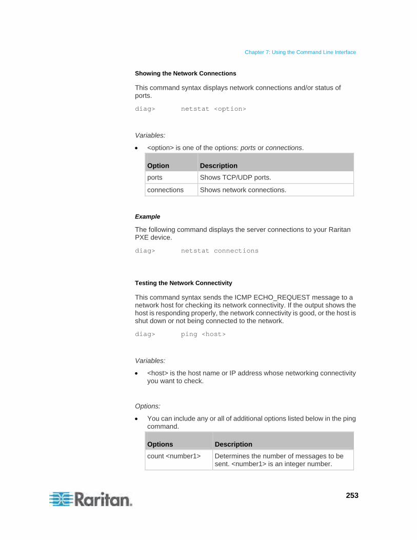
Chapter 7: Using the Command Line Interface
253
Showing the Network Connections
This command syntax displays network connections and/or status of ports.
diag> netstat <option>
Variables:
<option> is one of the options: ports or connections.
Option Description
ports Shows TCP/UDP ports.
connections Shows network connections.
Example
The following command displays the server connections to your Raritan PXE device.
diag> netstat connections
Testing the Network Connectivity
This command syntax sends the ICMP ECHO_REQUEST message to a network host for checking its network connectivity. If the output shows the host is responding properly, the network connectivity is good, or the host is shut down or not being connected to the network.
diag> ping <host>
Variables:
<host> is the host name or IP address whose networking connectivity you want to check.
Options:
You can include any or all of additional options listed below in the ping command.
Options Description
count <number1> Determines the number of messages to be sent. <number1> is an integer number.
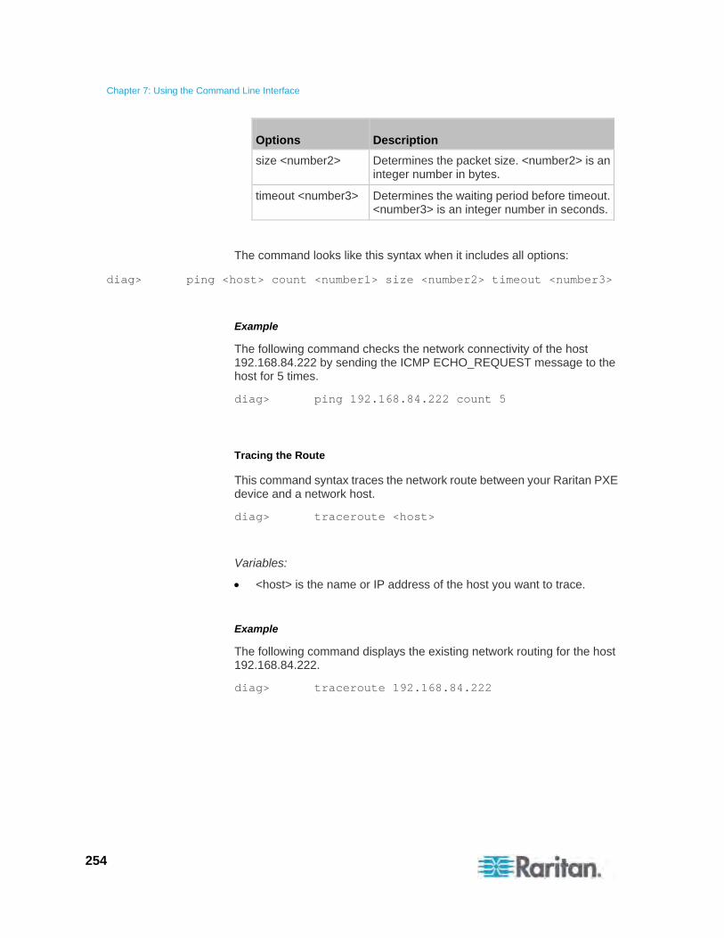
Chapter 7: Using the Command Line Interface
254
Options Description
size <number2> Determines the packet size. <number2> is an integer number in bytes.
timeout <number3> Determines the waiting period before timeout. <number3> is an integer number in seconds.
The command looks like this syntax when it includes all options:
diag> ping <host> count <number1> size <number2> timeout <number3>
Example
The following command checks the network connectivity of the host 192.168.84.222 by sending the ICMP ECHO_REQUEST message to the host for 5 times.
diag> ping 192.168.84.222 count 5
Tracing the Route
This command syntax traces the network route between your Raritan PXE device and a network host.
diag> traceroute <host>
Variables:
<host> is the name or IP address of the host you want to trace.
Example
The following command displays the existing network routing for the host 192.168.84.222.
diag> traceroute 192.168.84.222
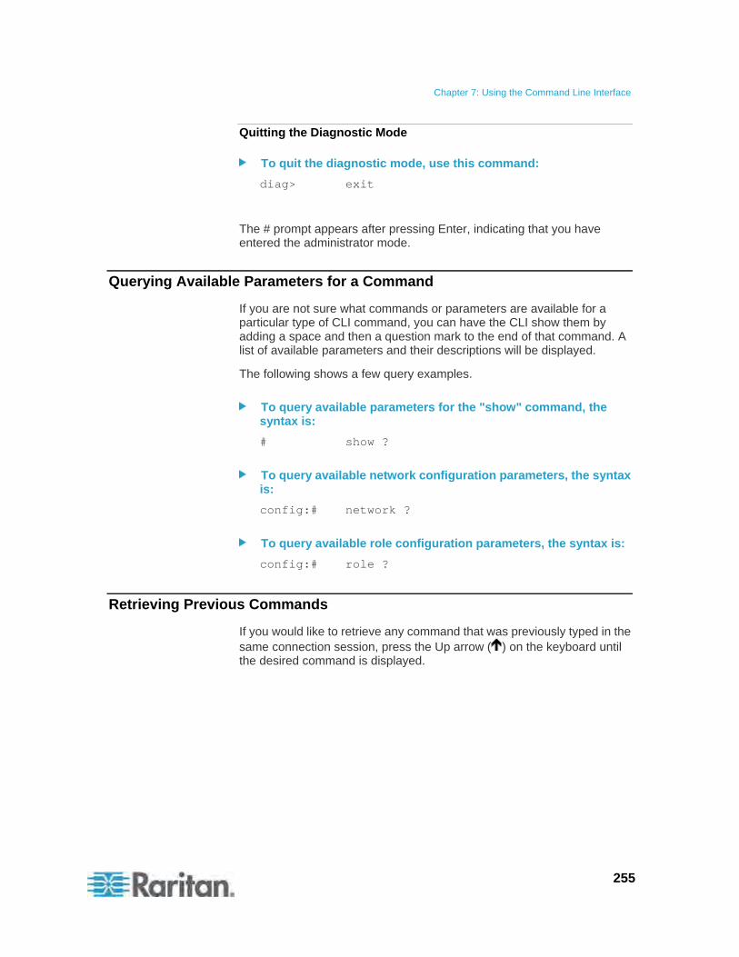
Chapter 7: Using the Command Line Interface
255
Quitting the Diagnostic Mode
To quit the diagnostic mode, use this command:
diag> exit
The # prompt appears after pressing Enter, indicating that you have entered the administrator mode.
Querying Available Parameters for a Command
If you are not sure what commands or parameters are available for a particular type of CLI command, you can have the CLI show them by adding a space and then a question mark to the end of that command. A list of available parameters and their descriptions will be displayed.
The following shows a few query examples.
To query available parameters for the "show" command, the syntax is:
# show ?
To query available network configuration parameters, the syntax is:
config:# network ?
To query available role configuration parameters, the syntax is:
config:# role ?
Retrieving Previous Commands
If you would like to retrieve any command that was previously typed in the same connection session, press the Up arrow ( ) on the keyboard until the desired command is displayed.
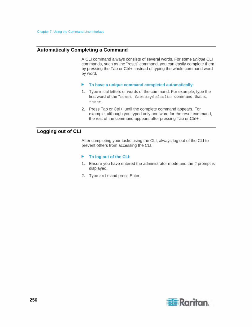
Chapter 7: Using the Command Line Interface
256
Automatically Completing a Command
A CLI command always consists of several words. For some unique CLI commands, such as the "reset" command, you can easily complete them by pressing the Tab or Ctrl+i instead of typing the whole command word by word.
To have a unique command completed automatically:
1. Type initial letters or words of the command. For example, type the first word of the "reset factorydefaults" command, that is, reset.
2. Press Tab or Ctrl+i until the complete command appears. For example, although you typed only one word for the reset command, the rest of the command appears after pressing Tab or Ctrl+i.
Logging out of CLI
After completing your tasks using the CLI, always log out of the CLI to prevent others from accessing the CLI.
To log out of the CLI:
1. Ensure you have entered the administrator mode and the # prompt is displayed.
2. Type exit and press Enter.
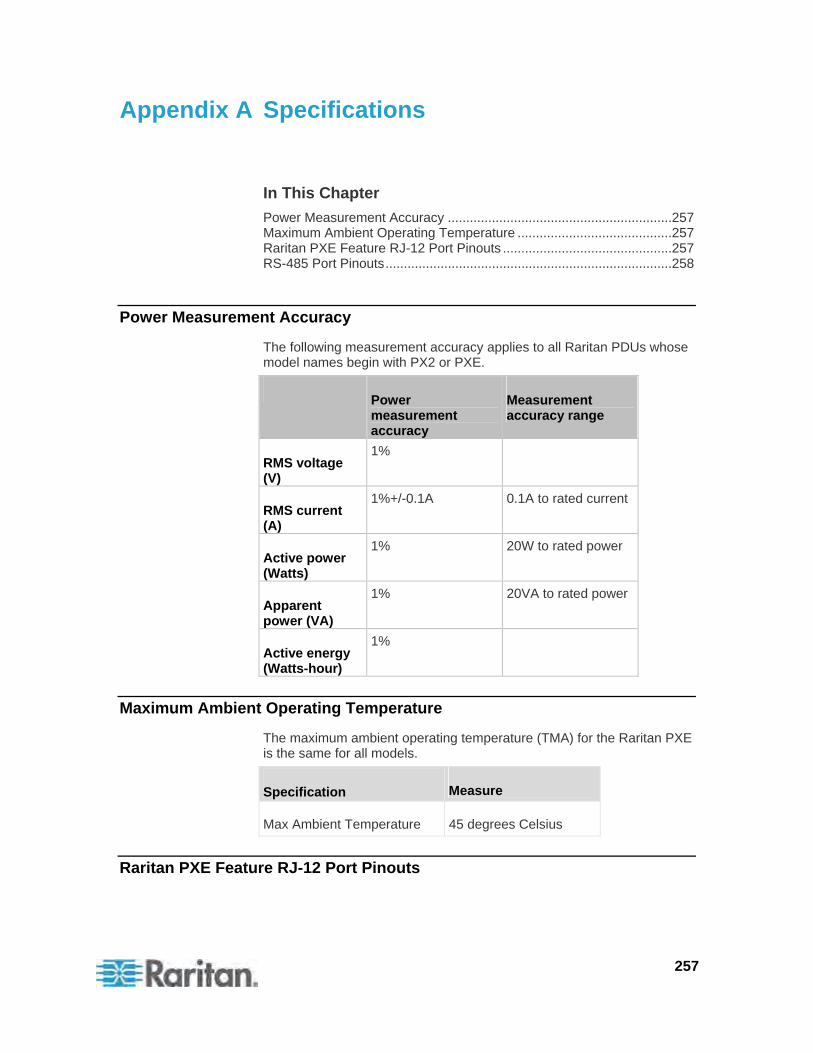
257
In This Chapter
Power Measurement Accuracy .............................................................257 Maximum Ambient Operating Temperature ..........................................257 Raritan PXE Feature RJ-12 Port Pinouts ..............................................257 RS-485 Port Pinouts..............................................................................258
Power Measurement Accuracy
The following measurement accuracy applies to all Raritan PDUs whose model names begin with PX2 or PXE.
Power measurement accuracy
Measurement accuracy range
RMS voltage (V)
1%
RMS current (A)
1%+/-0.1A 0.1A to rated current
Active power (Watts)
1% 20W to rated power
Apparent power (VA)
1% 20VA to rated power
Active energy (Watts-hour)
1%
Maximum Ambient Operating Temperature
The maximum ambient operating temperature (TMA) for the Raritan PXE is the same for all models.
Specification Measure
Max Ambient Temperature 45 degrees Celsius
Raritan PXE Feature RJ-12 Port Pinouts
Appendix A Specifications
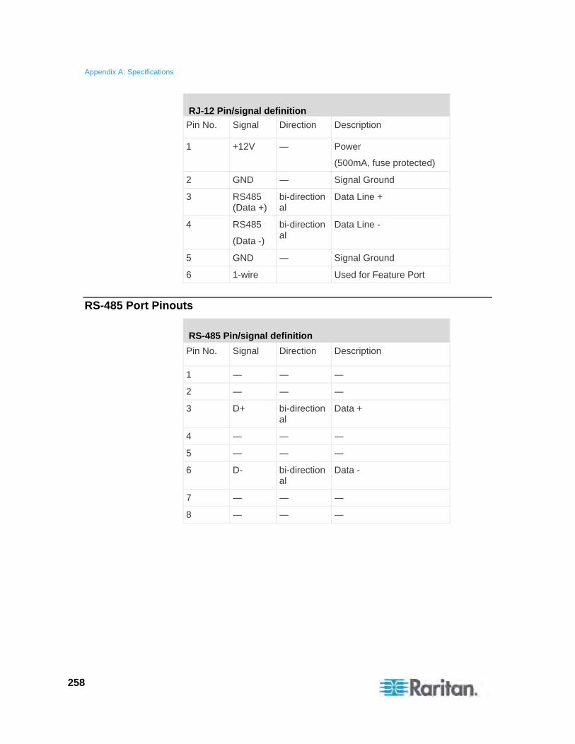
Appendix A: Specifications
258
RJ-12 Pin/signal definition
Pin No. Signal Direction Description
1 +12V ― Power
(500mA, fuse protected)
2 GND ― Signal Ground
3 RS485 (Data +)
bi-directional
Data Line +
4 RS485
(Data -)
bi-directional
Data Line -
5 GND ― Signal Ground
6 1-wire Used for Feature Port
RS-485 Port Pinouts
RS-485 Pin/signal definition
Pin No. Signal Direction Description
1 ― ― ―
2 ― ― ―
3 D+ bi-directional
Data +
4 ― ― ―
5 ― ― ―
6 D- bi-directional
Data -
7 ― ― ―
8 ― ― ―
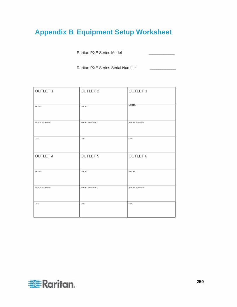
259
Raritan PXE Series Model ____________
Raritan PXE Series Serial Number ____________
OUTLET 1
OUTLET 2 OUTLET 3
MODEL
MODEL MODEL
SERIAL NUMBER
SERIAL NUMBER SERIAL NUMBER
USE
USE USE
OUTLET 4
OUTLET 5 OUTLET 6
MODEL
MODEL MODEL
SERIAL NUMBER
SERIAL NUMBER SERIAL NUMBER
USE
USE USE
Appendix B Equipment Setup Worksheet
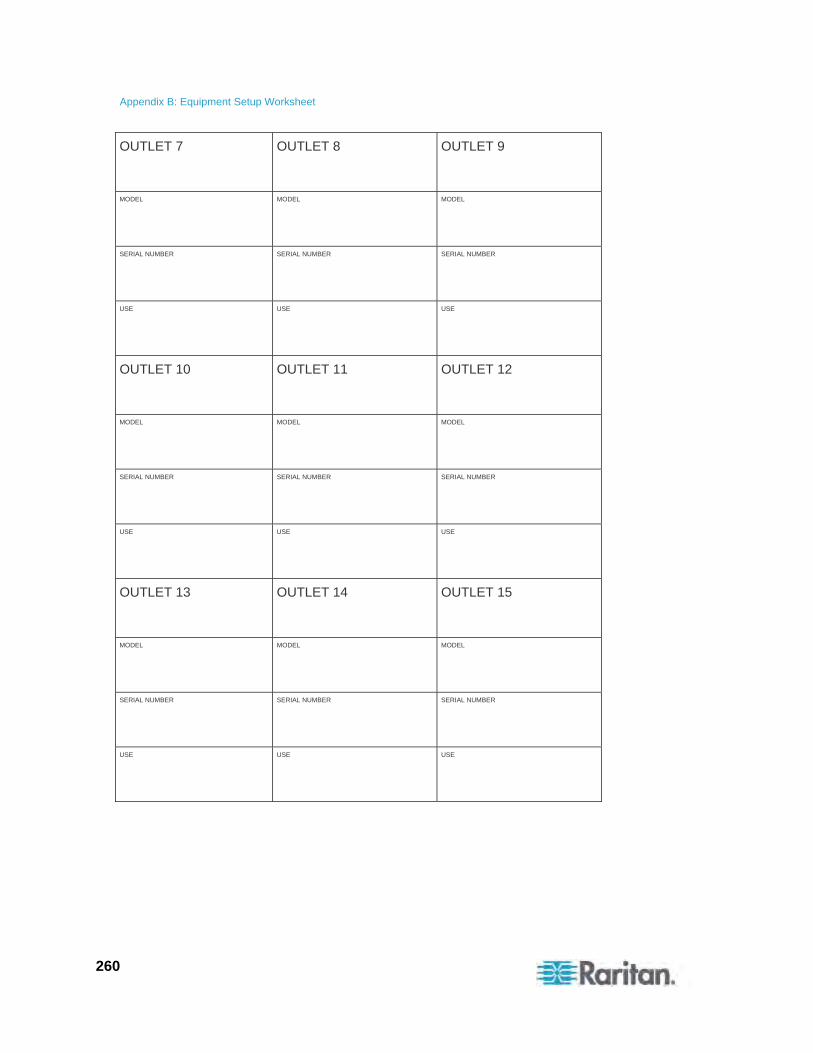
Appendix B: Equipment Setup Worksheet
260
OUTLET 7
OUTLET 8 OUTLET 9
MODEL
MODEL MODEL
SERIAL NUMBER
SERIAL NUMBER SERIAL NUMBER
USE
USE USE
OUTLET 10
OUTLET 11 OUTLET 12
MODEL
MODEL MODEL
SERIAL NUMBER
SERIAL NUMBER SERIAL NUMBER
USE
USE USE
OUTLET 13
OUTLET 14 OUTLET 15
MODEL
MODEL MODEL
SERIAL NUMBER
SERIAL NUMBER SERIAL NUMBER
USE
USE USE
Appendix B: Equipment Setup Worksheet
261
OUTLET 16
OUTLET 17 OUTLET 18
MODEL
MODEL MODEL
SERIAL NUMBER
SERIAL NUMBER SERIAL NUMBER
USE
USE USE
OUTLET 19
OUTLET 20 OUTLET 21
MODEL
MODEL MODEL
SERIAL NUMBER
SERIAL NUMBER SERIAL NUMBER
USE
USE USE
Appendix B: Equipment Setup Worksheet
262
OUTLET 22
OUTLET 23 OUTLET 24
MODEL
MODEL MODEL
SERIAL NUMBER
SERIAL NUMBER SERIAL NUMBER
USE
USE USE
Types of adapters
_________________________________________________________
Types of cables
_________________________________________________________
Name of software program
_________________________________________________________
263
For security reasons, the Raritan PXE device can be reset to factory defaults only at the local console.
Important: Exercise caution before resetting the Raritan PXE to its factory defaults. This erases existing information and customized settings, such as user profiles and threshold values.
In This Chapter
Using the CLI Command .......................................................................263
Using the CLI Command
The Command Line Interface (CLI) provides a reset command for restoring the Raritan PXE to factory defaults. For information on CLI, see Using the Command Line Interface (on page 148).
To reset to factory defaults using the CLI command:
1. Connect a computer to the Raritan PXE device. See Connecting the Raritan PXE to a Computer (on page 13).
2. Launch a terminal emulation program such as HyperTerminal, Kermit, or PuTTY, and open a window on the Raritan PXE. For information on the serial port configuration, see Step 2 of Initial Network Configuration (on page 15).
3. Log in to the CLI by typing the user name "admin" and its password. See Step 4 of Initial Network Configuration (on page 15).
4. After the # system prompt appears, type either of the following commands and press Enter.
# reset factorydefaults
-- OR --
# reset factorydefaults /y
5. If you entered the command without "/y" in Step 4, a message appears prompting you to confirm the operation. Type y to confirm the reset.
6. Wait until the Username prompt appears, indicating the reset is complete.
Appendix C Resetting to Factory Defaults
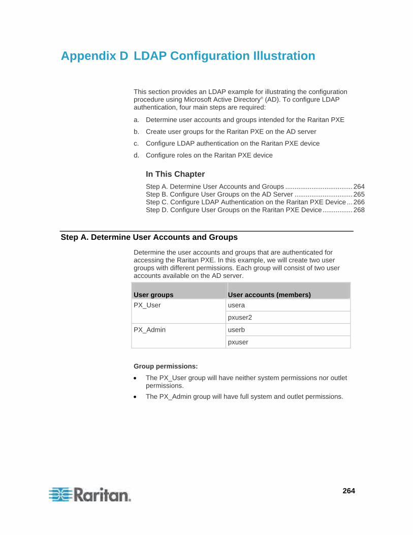
264
This section provides an LDAP example for illustrating the configuration procedure using Microsoft Active Directory® (AD). To configure LDAP authentication, four main steps are required:
a. Determine user accounts and groups intended for the Raritan PXE
b. Create user groups for the Raritan PXE on the AD server
c. Configure LDAP authentication on the Raritan PXE device
d. Configure roles on the Raritan PXE device
In This Chapter
Step A. Determine User Accounts and Groups .................................... 264 Step B. Configure User Groups on the AD Server ............................... 265 Step C. Configure LDAP Authentication on the Raritan PXE Device ... 266 Step D. Configure User Groups on the Raritan PXE Device................ 268
Step A. Determine User Accounts and Groups
Determine the user accounts and groups that are authenticated for accessing the Raritan PXE. In this example, we will create two user groups with different permissions. Each group will consist of two user accounts available on the AD server.
User groups User accounts (members)
usera PX_User
pxuser2
userb PX_Admin
pxuser
Group permissions:
The PX_User group will have neither system permissions nor outlet permissions.
The PX_Admin group will have full system and outlet permissions.
Appendix D LDAP Configuration Illustration
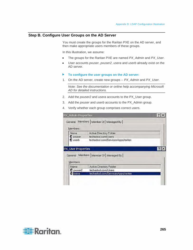
Appendix D: LDAP Configuration Illustration
265
Step B. Configure User Groups on the AD Server
You must create the groups for the Raritan PXE on the AD server, and then make appropriate users members of these groups.
In this illustration, we assume:
The groups for the Raritan PXE are named PX_Admin and PX_User.
User accounts pxuser, pxuser2, usera and userb already exist on the AD server.
To configure the user groups on the AD server:
1. On the AD server, create new groups -- PX_Admin and PX_User.
Note: See the documentation or online help accompanying Microsoft AD for detailed instructions.
2. Add the pxuser2 and usera accounts to the PX_User group.
3. Add the pxuser and userb accounts to the PX_Admin group.
4. Verify whether each group comprises correct users.
Appendix D: LDAP Configuration Illustration
266
Step C. Configure LDAP Authentication on the Raritan PXE Device
You must enable and set up LDAP authentication properly on the Raritan PXE device to use external authentication.
In the illustration, we assume:
The DNS server settings have been configured properly. See Modifying the Network Settings (on page 54) and Role of a DNS Server (on page 58).
The AD server's domain name is techadssl.com, and its IP address is 192.168.56.3.
The AD protocol is NOT encrypted over SSL.
The AD server uses the default TCP port 389.
Anonymous bind is used.
To configure LDAP authentication:
1. Choose Device Settings > Security > Authentication. The Authentication Settings dialog appears.
2. Select the LDAP radio button to activate remote LDAP/LDAPS server authentication.
3. Click New to add an LDAP/LDAPS server for authentication. The "Create new LDAP Server Configuration" dialog appears.
4. Provide the Raritan PXE with the information about the AD server.
IP Address / Hostname - Type the domain name techadssl.com or IP address 192.168.56.3.
Important: Without the SSL encryption enabled, you can type either the domain name or IP address in this field, but you must type the fully qualified domain name if the SSL encryption is enabled.
Use settings from LDAP server - Leave the checkbox deselected.
Type of LDAP Server - Select "Microsoft Active Directory" from the drop-down list.
LDAP over SSL - Have the checkbox deselected since the SSL encryption is not applied in this example.
Port - Ensure the field is set to 389.
SSL Port and Server Certificate - Skip the two fields since the SSL encryption is not enabled.
Use Bind Credentials - Do NOT select this checkbox because anonymous bind is used.
Bind DN, Bind Password and Confirm Bind Password -- Skip the three fields because anonymous bind is used.
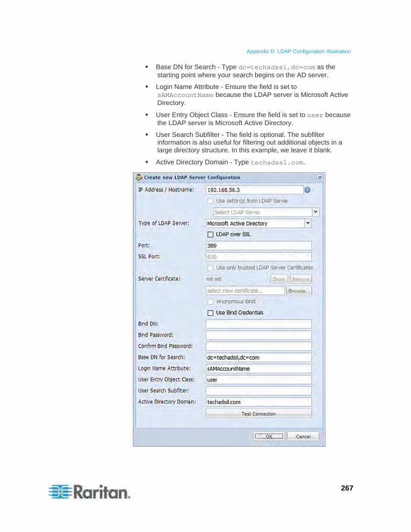
Appendix D: LDAP Configuration Illustration
267
Base DN for Search - Type dc=techadssl,dc=com as the starting point where your search begins on the AD server.
Login Name Attribute - Ensure the field is set to sAMAccountName because the LDAP server is Microsoft Active Directory.
User Entry Object Class - Ensure the field is set to user because the LDAP server is Microsoft Active Directory.
User Search Subfilter - The field is optional. The subfilter information is also useful for filtering out additional objects in a large directory structure. In this example, we leave it blank.
Active Directory Domain - Type techadssl.com.
Appendix D: LDAP Configuration Illustration
268
Note: For more information on LDAP configuration, see Setting Up LDAP Authentication (on page 92).
5. Click OK to save the changes. The LDAP server is saved.
6. Click OK to save the changes. The LDAP authentication is activated.
Note: If the Raritan PXE clock and the LDAP server clock are out of sync, the certificates are considered expired and users are unable to authenticate using LDAP. To ensure proper synchronization, administrators should configure the Raritan PXE and the LDAP server to use the same NTP server.
Step D. Configure User Groups on the Raritan PXE Device
A role on the Raritan PXE device determines the system and outlet permissions. You must create the roles whose names are identical to the user groups created for the Raritan PXE on the AD server or authorization will fail. Therefore, we will create the roles named PX_User and PX_Admin on the PDU.
In this illustration, we assume:
Users assigned to the PX_User role can neither configure Raritan PXE nor access the outlets.
Users assigned to the PX_Admin role have the Administrator permissions so they can both configure Raritan PXE and access the outlets.
To create the PX_User role with appropriate permissions assigned:
1. Choose User Management > Roles. The Manage Roles dialog appears.
Tip: You can also access the Manage Roles dialog by clicking the Manage Roles button in the Edit User 'XXX' dialog.
2. Click New. The Create New Role dialog appears.
3. Type PX_User in the Role Name field.
4. Type a description for the PX_User role in the Description field. In this example, we type "The role can only view PX settings" to describe the role.
5. Click the Privileges tab to select all View XXX permissions (where XXX is the name of the setting). A View XXX permission lets users view the XXX settings without the capability to configure or change them.
a. Click Add. The "Add Privileges to new Role" dialog appears.
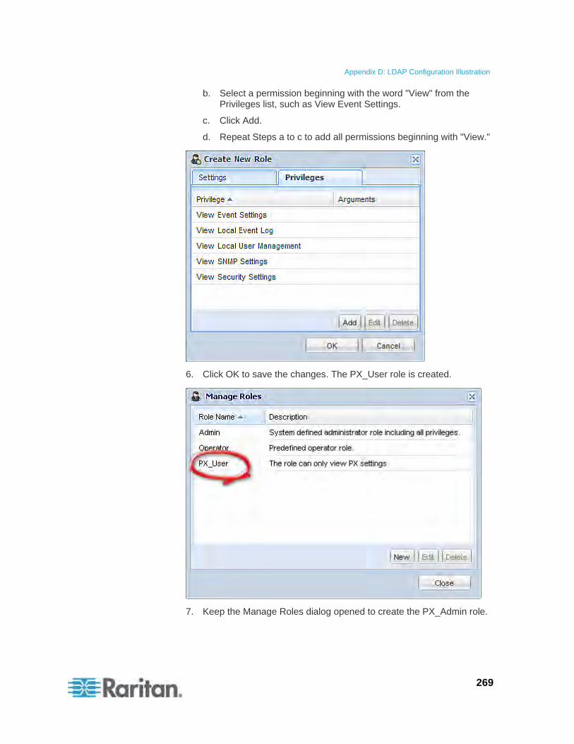
Appendix D: LDAP Configuration Illustration
269
b. Select a permission beginning with the word "View" from the Privileges list, such as View Event Settings.
c. Click Add.
d. Repeat Steps a to c to add all permissions beginning with "View."
6. Click OK to save the changes. The PX_User role is created.
7. Keep the Manage Roles dialog opened to create the PX_Admin role.
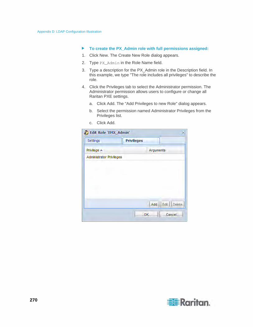
Appendix D: LDAP Configuration Illustration
270
To create the PX_Admin role with full permissions assigned:
1. Click New. The Create New Role dialog appears.
2. Type PX_Admin in the Role Name field.
3. Type a description for the PX_Admin role in the Description field. In this example, we type "The role includes all privileges" to describe the role.
4. Click the Privileges tab to select the Administrator permission. The Administrator permission allows users to configure or change all Raritan PXE settings.
a. Click Add. The "Add Privileges to new Role" dialog appears.
b. Select the permission named Administrator Privileges from the Privileges list.
c. Click Add.
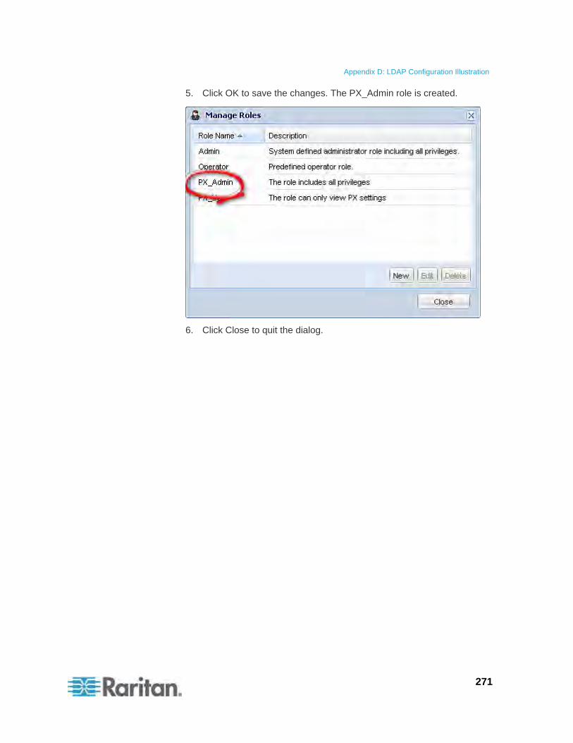
Appendix D: LDAP Configuration Illustration
271
5. Click OK to save the changes. The PX_Admin role is created.
6. Click Close to quit the dialog.
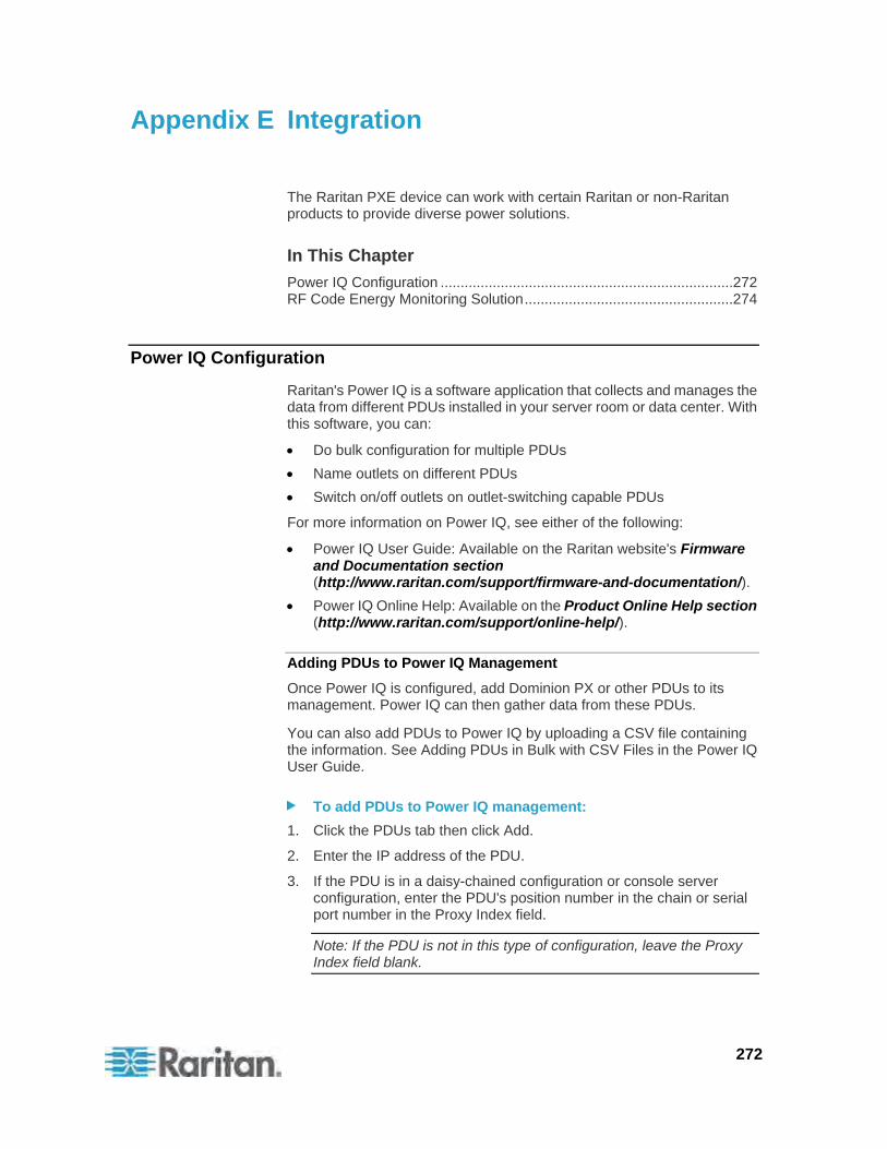
272
The Raritan PXE device can work with certain Raritan or non-Raritan products to provide diverse power solutions.
In This Chapter
Power IQ Configuration .........................................................................272 RF Code Energy Monitoring Solution....................................................274
Power IQ Configuration
Raritan's Power IQ is a software application that collects and manages the data from different PDUs installed in your server room or data center. With this software, you can:
Do bulk configuration for multiple PDUs
Name outlets on different PDUs
Switch on/off outlets on outlet-switching capable PDUs
For more information on Power IQ, see either of the following:
Power IQ User Guide: Available on the Raritan website's Firmware and Documentation section (http://www.raritan.com/support/firmware-and-documentation/).
Power IQ Online Help: Available on the Product Online Help section (http://www.raritan.com/support/online-help/).
Adding PDUs to Power IQ Management
Once Power IQ is configured, add Dominion PX or other PDUs to its management. Power IQ can then gather data from these PDUs.
You can also add PDUs to Power IQ by uploading a CSV file containing the information. See Adding PDUs in Bulk with CSV Files in the Power IQ User Guide.
To add PDUs to Power IQ management:
1. Click the PDUs tab then click Add.
2. Enter the IP address of the PDU.
3. If the PDU is in a daisy-chained configuration or console server configuration, enter the PDU's position number in the chain or serial port number in the Proxy Index field.
Note: If the PDU is not in this type of configuration, leave the Proxy Index field blank.
Appendix E Integration
Appendix E: Integration
273
4. If the PDU is a Dominion PX, enter a valid Username and Password for the PDU in the Dominion PX Credentials section. Re-enter the password in the Password Confirm field.
5. Select the SNMP Version.
For SNMP version 1/2c PDUs, enter an SNMP Community String that has at least READ permissions to this PDU. This enables polling the PDU for data. Enter an SNMP community string that has both READ and WRITE permissions to the PDU to enable power control, outlet renaming, and buffered data retrieval.
For SNMP version 3 PDUs, enter the Username and select an Authorization Level. The authorization levels are:
noAuthNoPriv - No Authentication Passkey, No Encoding Passkey
authNoPriv - Authentication Passkey, No Encoding Passkey
authPriv - Authentication Passkey, Encoding Passkey
a. Depending on the Authorization Level selected, you must enter additional credentials for Authorization and Privacy.
b. Authorization Protocol: Select MD5 or SHA.
c. Enter the PDU's Authorization Passkey, then re-enter the passkey in the Authorization Passkey Confirm field.
d. Privacy Protocol: Select DES or AES.
e. Enter the PDU's Privacy Passkey, then re-enter the passkey in the Privacy Passkey Confirm field.
Note: You must enable the SNMP agent on all PDUs added to Power IQ.
6. Select "Validate and wait for discovery to complete before proceeding" to check credentials and view the discovery process status as you add this PDU. Optional. See Validating PDU Credentials in the Power IQ User Guide.
7. Click Add.
Note: PDU discovery is complete once the PDU model type is determined. SNMP fields such as contact or location values are not determined until this device is polled for the first time.
Once added, the PDU appears in the PDU list. Power IQ begins polling the PDU for sensor data. You can configure how often Power IQ polls PDU. See Configuring Polling Intervals in the Power IQ User Guide.
Appendix E: Integration
274
RF Code Energy Monitoring Solution
With the RF Code active RFID hardware and management software and Raritan's PDUs combined, a wire-free energy monitoring solution that provides a picture of power utilization is offered.
This combined solution does not require any additional IP address configuration or association. All you need to do is plug an RF Code R170 PDU sensor tag into the SENSOR port of the Raritan PXE device.
The RF Code R170 PDU sensor tag collects the power data generated by Raritan PDUs and sends the data to the RF Code Sensor Manager software, which not only manages the power data but also make computations about the power usage from the collected data.
You can use the RF Code Sensor Manager to manage the power data using:
Live table views
Map views
Interactive graphing and reporting
Scheduled graphing and reporting
Alerting and thresholding
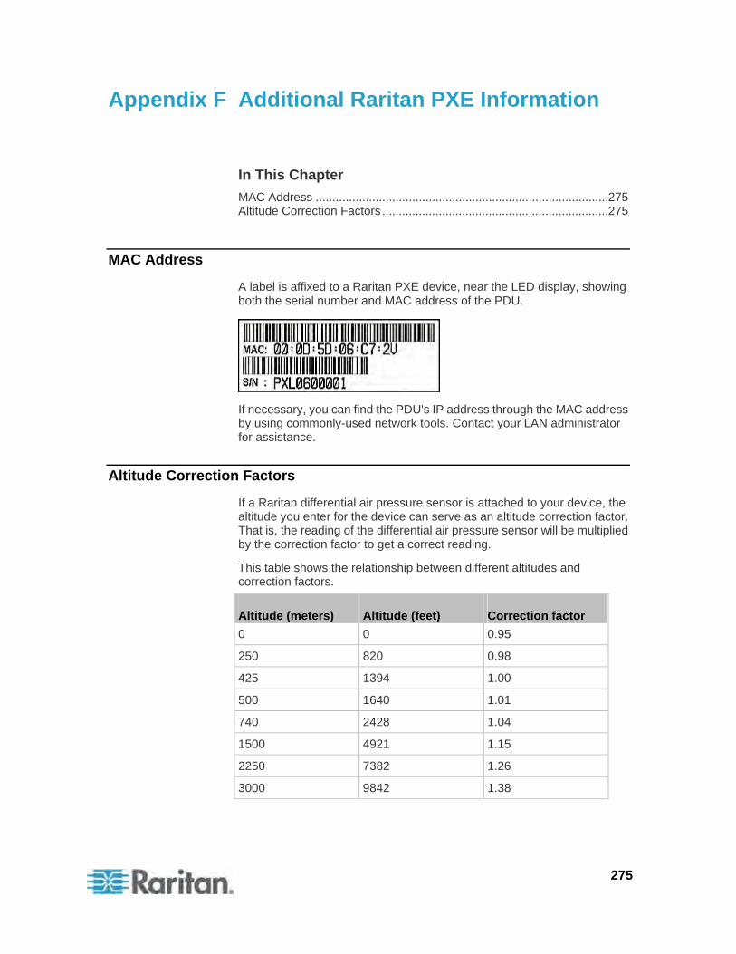
275
In This Chapter
MAC Address ........................................................................................275 Altitude Correction Factors ....................................................................275
MAC Address
A label is affixed to a Raritan PXE device, near the LED display, showing both the serial number and MAC address of the PDU.
If necessary, you can find the PDU's IP address through the MAC address by using commonly-used network tools. Contact your LAN administrator for assistance.
Altitude Correction Factors
If a Raritan differential air pressure sensor is attached to your device, the altitude you enter for the device can serve as an altitude correction factor. That is, the reading of the differential air pressure sensor will be multiplied by the correction factor to get a correct reading.
This table shows the relationship between different altitudes and correction factors.
Altitude (meters) Altitude (feet) Correction factor
0 0 0.95
250 820 0.98
425 1394 1.00
500 1640 1.01
740 2428 1.04
1500 4921 1.15
2250 7382 1.26
3000 9842 1.38
Appendix F Additional Raritan PXE Information

Appendix F: Additional Raritan PXE Information
276
277
1
1U Products • 3
A
A Note about Enabling Thresholds • 147 A Note about Firmware Upgrade Time • 138 A Note about Untriggered Rules • 115 About Contact Closure Sensors • 24 About the Interface • 148 Access Security Control • 75 Accessing the Help • 139 Add Page Icon • 42, 45 Adding a Firewall Rule • 187, 189 Adding a Role-Based Access Control Rule •
202 Adding IT Devices for Ping Monitoring • 117 Adding PDUs to Power IQ Management • 272 Adding the LDAP Server Settings • 93 Additional Raritan PXE Information • 275 Adjusting the Pane • 44 All Privileges • 242, 245 Altitude Correction Factors • 64, 167, 275 Automatic Mode • 31 Automatically Completing a Command • 256
B
Beeper • 35 Before You Begin • 10 Browser-Defined Shortcut Menu • 50 Browsing through the Online Help • 140
C
Certificate Signing Request • 88 Changing a User's Password • 232 Changing the Circuit Breaker Name • 206 Changing the Column • 49 Changing the Default Policy • 76, 77, 84 Changing the HTTP Port • 180 Changing the HTTP(S) Settings • 58 Changing the HTTPS Port • 180 Changing the Inlet Name • 206 Changing the LAN Duplex Mode • 179 Changing the LAN Interface Speed • 178
Changing the Measurement Units • 64, 132, 239
Changing the Outlet Name • 205 Changing the PDU Name • 166 Changing the Role List View • 75 Changing the Role(s) • 238 Changing the Sensor Description • 211 Changing the Sensor Name • 207 Changing the Sorting • 49, 117, 119 Changing the SSH Configuration • 181 Changing the SSH Port • 182 Changing the SSH Settings • 59, 70 Changing the Telnet Configuration • 180 Changing the Telnet Port • 181 Changing the Telnet Settings • 59 Changing the UDP Port • 248 Changing the User List View • 72 Changing the View of a List • 48, 53, 72, 75,
116, 135, 139 Changing Your Own Password • 241 Changing Your Password • 38 Checking Associated Circuit Breakers • 99 Checking Server Monitoring States • 119 Checking the Branch Circuit Rating • 11 Circuit Breaker Configuration Commands • 206 Circuit Breaker Information • 156 Circuit Breaker Orientation Limitation • 4, 6, 8 Circuit Breakers • 33 Clearing Event Entries • 116 Closing a Serial Connection • 151 Collapsing the Tree • 43 Command History • 163 Commands for Environmental Sensors • 225 Commands for Inlet Pole Sensors • 217 Commands for Inlet Sensors • 211 Components of an Event Rule • 105 Configuring a Contact Closure Sensor • 25, 26,
128 Configuring Environmental Sensors • 48, 120,
123 Configuring Event Rules • 66, 102, 105, 108,
144 Configuring IP Protocol Settings • 169 Configuring SNMP Traps • 144 Configuring the Firewall • 76 Configuring the IPv4 Parameters • 170 Configuring the IPv6 Parameters • 175 Configuring the Raritan PXE • 12, 54
Index
Index
278
Configuring the Raritan PXE Device and Network • 165
Configuring the SMTP Settings • 66, 106 Configuring the SNMP Settings • 60, 69 Configuring Users for Encrypted SNMP v3 • 60,
143 Connecting Environmental Sensors (Optional)
• 22, 120 Connecting the PDU to a Power Source • 11 Connecting the Raritan PXE to a Computer •
13, 263 Connecting the Raritan PXE to Your Network •
15 Connecting Third-Party Detectors/Switches to
DPX-CC2-TR • 24 Connection Ports • 29 Contact Closure Sensor LEDs • 26 Copying a Raritan PXE Configuration • 132 Copying Configurations with Bulk Configuration
• 130 Creating a Certificate Signing Request • 88 Creating a Role • 71, 73, 241 Creating a Self-Signed Certificate • 90 Creating a User Profile • 37, 59, 68, 72, 73, 74,
133, 143, 230 Creating Actions • 106 Creating an Event Rule • 105 Creating Firewall Rules • 76, 78 Creating Role-Based Access Control Rules •
84, 85 Creating Rules • 108
D
Data Pane • 46 Deleting a Firewall Rule • 192 Deleting a Role • 75, 246 Deleting a Role-Based Access Control Rule •
205 Deleting a User Profile • 72, 240 Deleting an Event Rule or Action • 114 Deleting Firewall Rules • 80 Deleting Ping Monitoring Settings • 119 Deleting Role-Based Access Control Rules • 87 Deleting the LDAP Server Settings • 97 Describing the Sensor Location • 124, 125 Device Management • 51 Diagnostic Commands • 252 Different CLI Modes and Prompts • 149, 150,
151, 165 Disabling the LDAP Authentication • 97
Displaying the PDU Information • 52, 99 Dominion PX Explorer Pane • 41 Downloading Diagnostic Information • 136 Downloading Key and Certificate Files • 92 Downloading SNMP MIB • 61, 143, 144, 145
E
Editing Firewall Rules • 80 Editing Ping Monitoring Settings • 118 Editing Role-Based Access Control Rules • 86 Editing the LDAP Server Settings • 97 Enabling Data Logging • 65 Enabling IPv4 or IPv6 • 169 Enabling LDAP and Local Authentication
Services • 98 Enabling Login Limitations • 82 Enabling or Disabling a User Profile • 234 Enabling or Disabling Data Logging • 166 Enabling or Disabling EnergyWise • 246 Enabling or Disabling SNMP v1/v2c • 183 Enabling or Disabling SNMP v3 • 183 Enabling or Disabling SSH • 182 Enabling or Disabling Strong Passwords • 196 Enabling or Disabling Telnet • 181 Enabling Password Aging • 83 Enabling SNMP • 65, 142 Enabling Strong Passwords • 83 Enabling the Feature • 84 Enabling the Firewall • 76, 77 Enabling User Blocking • 81 EnergyWise Configuration Commands • 246 EnergyWise Settings • 162 Entering the Configuration Mode • 151, 165,
232, 241 Entering the Diagnostic Mode • 151, 252 Environmental Sensor Configuration
Commands • 207 Environmental Sensor Information • 157 Environmental Sensor Threshold Information •
160 Environmental Sensors • 120 Equipment Setup Worksheet • 11, 259

Index
279
Example • 166, 167, 168, 169, 170, 171, 172, 173, 174, 175, 176, 177, 178, 179, 180, 181, 182, 183, 184, 185, 187, 188, 190, 191, 192, 193, 194, 195, 196, 197, 198, 199, 200, 201, 203, 204, 205, 206, 207, 208, 209, 210, 211, 212, 213, 214, 215, 216, 217, 219, 220, 221, 223, 224, 225, 226, 227, 228, 229, 230, 231, 232, 233, 234, 238, 240, 241, 243, 245, 246, 247, 248, 252, 253, 254 When Hysteresis is Useful • 104 When to Disable Hysteresis • 104
Example 1 - Basic Security Information • 164 Example 1 - Combination of IP, Subnet Mask
and Gateway Parameters • 249 Example 2 - Combination of Upper Critical and
Upper Warning Settings • 249 Example 2 - In-Depth Security Information •
164 Example 3 - Basic PDU Information • 164 Example 4 - In-Depth PDU Information • 165 Examples • 163 Existing Roles • 162 Existing User Profiles • 161 Expanding the Tree • 41, 42, 98, 99, 100, 101,
102, 121, 122, 123, 126, 129
F
Filling Out the Equipment Setup Worksheet • 11
Firewall Control • 186 Firmware Upgrade • 132, 136 Forcing a Password Change • 234 Forcing HTTPS Encryption • 58, 76, 87 Full Disaster Recovery • 139
G
Gathering the LDAP Information • 93
H
Help Command • 151 History Buffer Length • 163 How to Connect Differential Air Pressure
Sensors • 27 How to Use the Calendar • 62, 63 HTTPS Access • 192
I Identifying Environmental Sensors • 120, 121,
122 Idle Timeout • 195 Initial Network Configuration • 15, 37, 44, 54,
263 Inlet and Circuit Breaker Management • 99 Inlet Configuration Commands • 205 Inlet Information • 155 Inlet Pole Sensor Threshold Information • 159 Inlet Sensor Threshold Information • 158 Installation and Configuration • 10 Installing a CA-Signed Certificate • 89 Installing Cable Retention Clips on Outlets
(Optional) • 20 Installing Existing Key and Certificate Files • 91 Installing the USB-to-Serial Driver • 13 Integration • 272 Introduction • 1 Introduction to the Web Interface • 40 IP Configuration • 152
L
LAN Interface Settings • 153 Layout • 146 LDAP Configuration Illustration • 96, 264 LED Display • 30 LEDs for Measurement Units • 31, 32 Listing TCP Connections • 135 Logging in to CLI • 148 Logging in to the Web Interface • 37 Logging out of CLI • 256 Login • 37 Login Limitation • 193 Logout • 39 Logout Button • 46 Lowercase Character Requirement • 197
M
MAC Address • 12, 275 Managing Environmental Sensors • 120, 122 Managing Event Logging • 115 Managing Firewall Rules • 188 Managing Role-Based Access Control Rules •
202 Manual Mode • 32 Maximum Ambient Operating Temperature •
11, 257
Index
280
Maximum Password History • 200 Maximum Password Length • 197 Menus • 41 Minimum Password Length • 197 Modifying a Firewall Rule • 190 Modifying a Role • 71, 72, 74, 244 Modifying a Role-Based Access Control Rule •
203 Modifying a User Profile • 39, 71, 74, 231 Modifying a User's Personal Data • 233 Modifying an Action • 61, 114 Modifying an Event Rule • 113 Modifying the Firewall Control Parameters •
186 Modifying the IPv4 Settings • 55 Modifying the IPv6 Settings • 57 Modifying the Network Configuration • 53 Modifying the Network Interface Settings • 54 Modifying the Network Service Settings • 58,
148, 150 Modifying the Network Settings • 44, 54, 266 Modifying the Role-Based Access Control
Parameters • 201 Modifying the SNMPv3 Settings • 235 Monitoring Server Accessibility • 117 Monitoring the Inlet • 100 More Information • 46 More Information about AD Configuration • 96 Mounting 1U Models Using L-Brackets and
Buttons • 5 Mounting Zero U Models Using L-Brackets and
Buttons • 8 Mounting Zero U Models Using Two Rear
Buttons • 6 Multi-Command Syntax • 186, 193, 195, 196,
201, 231, 233, 235, 239, 249
N
Naming Circuit Breakers • 101 Naming Outlets • 98 Naming the Inlet • 100 Naming the PDU • 41, 42, 43, 44, 53, 64, 121,
122, 123, 124, 126, 129 Network Configuration • 152 Network Diagnostics • 134 Network Service Settings • 153 Network Troubleshooting • 134, 251 Networking Configuration Commands • 168 Networking Mode • 153 Numeric Character Requirement • 198
O
Outlet Configuration Commands • 205 Outlet Information • 154 Outlet Management • 98 Outlets • 28 Overriding the IPv4 DHCP-Assigned DNS
Server • 174 Overriding the IPv6 DHCP-Assigned DNS
Server • 177, 178
P
Package Contents • 2, 10 Panel Components • 28 Password Aging • 194 Password Aging Interval • 194 PDU Configuration • 154 PDU Configuration Commands • 166 Pinging a Host • 134 Power Cord • 28 Power IQ Configuration • 272 Power Measurement Accuracy • 257 Preparing the Installation Site • 10 Product Features • 1 Product Models • 1
Q
Querying Available Parameters for a Command • 151, 255
Querying the DNS Servers • 252 Quitting the Configuration Mode • 166, 250 Quitting the Diagnostic Mode • 255
R
Rackmount Safety Guidelines • 4 Rack-Mounting the PDU • 4 Raritan PXE Feature RJ-12 Port Pinouts • 257 Rebooting the Raritan PXE Device • 67 Reliability Data • 162 Reliability Error Log • 163 Reset Button • 33 Resetting the Button-Type Circuit Breaker • 33 Resetting the Handle-Type Circuit Breaker • 34 Resetting the Raritan PXE • 251 Resetting to Factory Defaults • 251, 263 Resizing a Dialog • 50, 53, 116, 135 Restarting the PDU • 251 Retrieving Previous Commands • 255
Index
281
Retrieving Software Packages Information • 139
RF Code Energy Monitoring Solution • 274 Role Configuration Commands • 241 Role of a DNS Server • 58, 266 Role-Bassed Access Control • 200 RS-485 Port Pinouts • 258
S
Safety Guidelines • ii Safety Instructions • iii, 11 Sample Event Rules • 112 Sample Inlet-Level Event Rule • 112 Sample PDU-Level Event Rule • 112 Saving a Raritan PXE Configuration • 131 Security Configuration Commands • 185 Security Settings • 161 Selecting IPv4 or IPv6 Addresses • 170 Selecting the Internet Protocol • 55, 57 Sensor Measurement Accuracy • 127 Sensor Threshold Configuration Commands •
211 Setting Data Logging • 65, 167 Setting Inlet Thresholds • 102 Setting Power Thresholds • 48, 102, 147 Setting the Data Logging Measurements Per
Entry • 167 Setting the Date and Time • 61 Setting the EnergyWise Configuration • 67 Setting the History Buffer Length • 249 Setting the Inlet Pole's Assertion Timeout • 224 Setting the Inlet Pole's Deassertion Hysteresis
• 223 Setting the Inlet's Assertion Timeout • 217 Setting the Inlet's Deassertion Hysteresis • 216 Setting the Inlet's Lower Critical Threshold •
214 Setting the Inlet's Lower Warning Threshold •
215 Setting the Inlet's Upper Critical Threshold •
212 Setting the Inlet's Upper Warning Threshold •
213 Setting the IPv4 Address • 172 Setting the IPv4 Configuration Mode • 170 Setting the IPv4 Gateway • 173 Setting the IPv4 Primary DNS Server • 173 Setting the IPv4 Secondary DNS Server • 174 Setting the IPv4 Subnet Mask • 172 Setting the IPv6 Address • 176 Setting the IPv6 Configuration Mode • 175
Setting the IPv6 Gateway • 176 Setting the IPv6 Primary DNS Server • 177 Setting the IPv6 Secondary DNS Server • 177 Setting the LAN Interface Parameters • 178 Setting the Lower Critical Threshold for an Inlet
Pole • 220 Setting the Lower Warning Threshold for an
Inlet Pole • 221 Setting the Network Service Parameters • 179 Setting the Polling Interval • 248 Setting the Preferred Host Name • 171 Setting the Sensor's Assertion Timeout • 229 Setting the Sensor's Deassertion Hysteresis •
229 Setting the Sensor's Lower Critical Threshold •
227 Setting the Sensor's Lower Warning Threshold
• 228 Setting the Sensor's Upper Critical Threshold •
225 Setting the Sensor's Upper Warning Threshold
• 226 Setting the SNMP Configuration • 182 Setting the SNMP Read Community • 184 Setting the SNMP Write Community • 184 Setting the sysContact Value • 184 Setting the sysLocation Value • 185 Setting the sysName Value • 185 Setting the Upper Critical Threshold for an Inlet
Pole • 218 Setting the Upper Warning Threshold for an
Inlet Pole • 219 Setting the X Coordinate • 209 Setting the Y Coordinate • 209 Setting the Z Coordinate • 168, 210 Setting the Z Coordinate Format • 124 Setting the Z Coordinate Format for
Environmental Sensors • 168, 210 Setting Up an SSL Certificate • 75, 87 Setting Up LDAP Authentication • 58, 75, 92,
268 Setting Up Role-Based Access Control Rules •
84 Setting Up Roles • 38, 65, 68, 71, 73 Setting Up User Login Controls • 81 Setup Button • 44 Showing Information • 152 Showing the Network Connections • 253 Single Login Limitation • 193 SNMP Gets and Sets • 145 SNMP Sets and Thresholds • 147 Sorting Firewall Rules • 80
Index
282
Sorting Role-Based Access Control Rules • 86 Sorting the LDAP Access Order • 96 Special Character Requirement • 199 Specifications • 4, 257 Specifying the Device Altitude • 64, 167 Specifying the EnergyWise Domain • 247 Specifying the EnergyWise Secret • 247 Specifying the Sensor Type • 208 States of Managed Sensors • 127 Status Bar • 44 Step A. Determine User Accounts and Groups •
264 Step B. Configure User Groups on the AD
Server • 265 Step C. Configure LDAP Authentication on the
Raritan PXE Device • 266 Step D. Configure User Groups on the Raritan
PXE Device • 268 Strong Passwords • 196 Supported Web Browsers • 36
T
Testing the LDAP Server Connection • 96 Testing the Network Connectivity • 253 The Raritan PXE MIB • 145 The Yellow- or Red-Highlighted Reading • 47,
51, 100, 126 Three-Digit Row • 30 Tracing the Network Route • 134 Tracing the Route • 254 Two-Digit Row • 31
U
Unblocking a User • 81, 250 Unmanaging Environmental Sensors • 123,
129 Unpacking the Product and Components • 10 Updating the Raritan PXE Firmware • 137 Uppercase Character Requirement • 198 User Blocking • 195 User Configuration Commands • 230 User Management • 68 Using SNMP • 138, 142 Using the CLI Command • 251, 263 Using the Command Line Interface • 58, 125,
148, 263 Using the PDU • 28 Using the Web Interface • 15, 36
V
Viewing Connected Users • 116 Viewing Firmware Update History • 138 Viewing Sensor Data • 126 Viewing the Communication Log • 45, 135 Viewing the Dashboard • 51 Viewing the Local Event Log • 115
W
Warning Icon • 47 What is Assertion Timeout? • 103, 104, 124,
217, 225, 230 What is Deassertion Hysteresis? • 102, 103,
115, 124, 216, 224, 229 With HyperTerminal • 149, 250 With SSH or Telnet • 150
Z
Zero U Products • 3

U.S./Canada/Latin America Monday - Friday 8 a.m. - 6 p.m. ET Phone: 800-724-8090 or 732-764-8886 For CommandCenter NOC: Press 6, then Press 1 For CommandCenter Secure Gateway: Press 6, then Press 2 Fax: 732-764-8887 Email for CommandCenter NOC: [email protected] Email for all other products: [email protected]
China
Beijing Monday - Friday 9 a.m. - 6 p.m. local time Phone: +86-10-88091890
Shanghai Monday - Friday 9 a.m. - 6 p.m. local time Phone: +86-21-5425-2499
GuangZhou Monday - Friday 9 a.m. - 6 p.m. local time Phone: +86-20-8755-5561
India Monday - Friday 9 a.m. - 6 p.m. local time Phone: +91-124-410-7881
Japan Monday - Friday 9:30 a.m. - 5:30 p.m. local time Phone: +81-3-3523-5991 Email: [email protected]
Europe
Europe Monday - Friday 8:30 a.m. - 5 p.m. GMT+1 CET Phone: +31-10-2844040 Email: [email protected]
United Kingdom Monday - Friday 8:30 a.m. to 5 p.m. GMT Phone +44(0)20-7090-1390
France Monday - Friday 8:30 a.m. - 5 p.m. GMT+1 CET Phone: +33-1-47-56-20-39
Germany Monday - Friday 8:30 a.m. - 5:30 p.m. GMT+1 CET Phone: +49-20-17-47-98-0 Email: [email protected]
Melbourne, Australia Monday - Friday 9:00 a.m. - 6 p.m. local time Phone: +61-3-9866-6887
Taiwan Monday - Friday 9 a.m. - 6 p.m. GMT -5 Standard -4 Daylight Phone: +886-2-8919-1333 Email: [email protected]