Embed Size (px)
Citation preview

Raymond A. Serway
Jerry S. Faughn
367
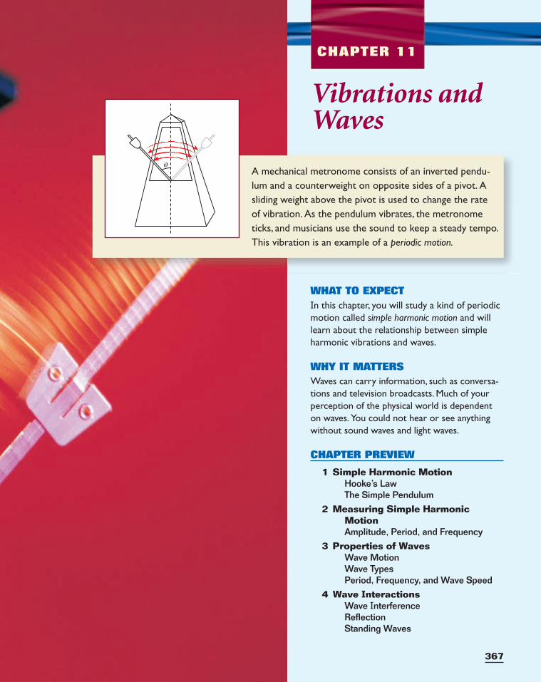
A mechanical metronome consists of an inverted pendu-lum and a counterweight on opposite sides of a pivot. Asliding weight above the pivot is used to change the rate of vibration. As the pendulum vibrates, the metronometicks, and musicians use the sound to keep a steady tempo.This vibration is an example of a periodic motion.
CHAPTER 11
o
Vibrations andWaves
WHAT TO EXPECTIn this chapter, you will study a kind of periodicmotion called simple harmonic motion and willlearn about the relationship between simpleharmonic vibrations and waves.
WHY IT MATTERSWaves can carry information, such as conversa-tions and television broadcasts. Much of yourperception of the physical world is dependenton waves. You could not hear or see anythingwithout sound waves and light waves.
CHAPTER PREVIEW
1 Simple Harmonic MotionHooke’s LawThe Simple Pendulum
2 Measuring Simple HarmonicMotionAmplitude, Period, and Frequency
3 Properties of WavesWave MotionWave TypesPeriod, Frequency, and Wave Speed
4 Wave InteractionsWave InterferenceReflectionStanding Waves
Simple Harmonic MotionSECTION 1
HOOKE’S LAW
A repeated motion, such as that of an acrobat swinging on a trapeze, is called
a periodic motion. Other periodic motions include those made by a child on a
playground swing, a wrecking ball swaying to and fro, and the pendulum of a
grandfather clock or a metronome. In each of these cases, the periodic motion
is back and forth over the same path.
One of the simplest types of back-and-forth periodic motion is the motion
of a mass attached to a spring, as shown in Figure 1. Let us assume that the
mass moves on a frictionless horizontal surface. When the spring is stretched
or compressed and then released, it vibrates back and forth about its
unstretched position. We will begin by considering this example, and then we
will apply our conclusions to the swinging motion of a trapeze acrobat.
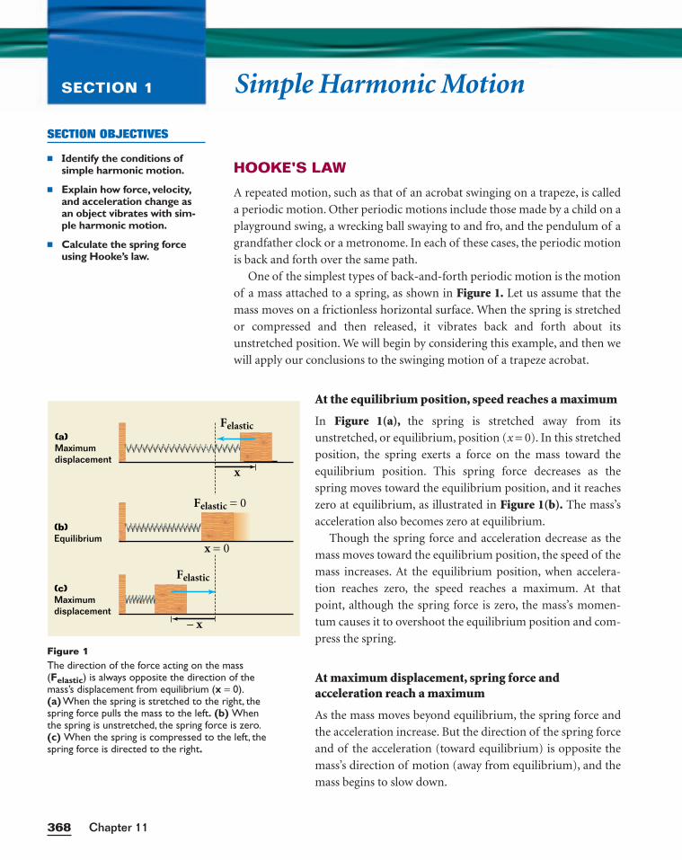
At the equilibrium position, speed reaches a maximum
In Figure 1(a), the spring is stretched away from its
unstretched, or equilibrium, position (x = 0). In this stretched
position, the spring exerts a force on the mass toward the
equilibrium position. This spring force decreases as the
spring moves toward the equilibrium position, and it reaches
zero at equilibrium, as illustrated in Figure 1(b). The mass’s
acceleration also becomes zero at equilibrium.
Though the spring force and acceleration decrease as the
mass moves toward the equilibrium position, the speed of the
mass increases. At the equilibrium position, when accelera-
tion reaches zero, the speed reaches a maximum. At that
point, although the spring force is zero, the mass’s momen-
tum causes it to overshoot the equilibrium position and com-
press the spring.
At maximum displacement, spring force andacceleration reach a maximum
As the mass moves beyond equilibrium, the spring force and
the acceleration increase. But the direction of the spring force
and of the acceleration (toward equilibrium) is opposite the
mass’s direction of motion (away from equilibrium), and the
mass begins to slow down.
Chapter 11368
SECTION OBJECTIVES
■ Identify the conditions ofsimple harmonic motion.
■ Explain how force, velocity,and acceleration change asan object vibrates with sim-ple harmonic motion.
■ Calculate the spring forceusing Hooke’s law.
(a) Maximumdisplacement
(b) Equilibrium
(c) Maximumdisplacement
x
– x
Felastic
Felastic = 0
Felastic
x = 0
Figure 1The direction of the force acting on the mass(Felastic) is always opposite the direction of themass’s displacement from equilibrium (x = 0).(a) When the spring is stretched to the right, thespring force pulls the mass to the left. (b) Whenthe spring is unstretched, the spring force is zero.(c) When the spring is compressed to the left, thespring force is directed to the right.
1. Earth’s Orbit
The motion of Earth orbitingthe sun is periodic. Is this mo-tion simple harmonic? Whyor why not?
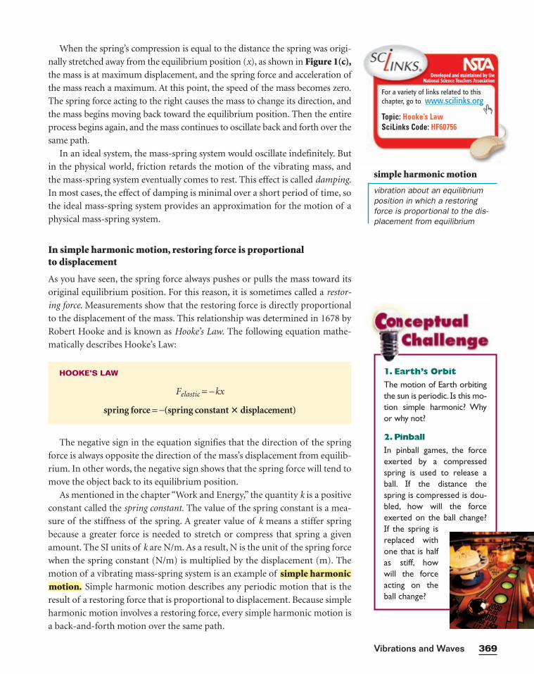
2.Pinball
In pinball games, the forceexerted by a compressedspring is used to release aball. If the distance thespring is compressed is dou-bled, how will the forceexerted on the ball change?If the spring isreplaced withone that is halfas stiff, howwill the forceacting on theball change?
When the spring’s compression is equal to the distance the spring was origi-
nally stretched away from the equilibrium position (x), as shown in Figure 1(c),the mass is at maximum displacement, and the spring force and acceleration of
the mass reach a maximum. At this point, the speed of the mass becomes zero.
The spring force acting to the right causes the mass to change its direction, and
the mass begins moving back toward the equilibrium position. Then the entire
process begins again, and the mass continues to oscillate back and forth over the
same path.
In an ideal system, the mass-spring system would oscillate indefinitely. But
in the physical world, friction retards the motion of the vibrating mass, and
the mass-spring system eventually comes to rest. This effect is called damping.
In most cases, the effect of damping is minimal over a short period of time, so
the ideal mass-spring system provides an approximation for the motion of a
physical mass-spring system.
In simple harmonic motion, restoring force is proportional to displacement
As you have seen, the spring force always pushes or pulls the mass toward its
original equilibrium position. For this reason, it is sometimes called a restor-
ing force. Measurements show that the restoring force is directly proportional
to the displacement of the mass. This relationship was determined in 1678 by
Robert Hooke and is known as Hooke’s Law. The following equation mathe-
matically describes Hooke’s Law:
The negative sign in the equation signifies that the direction of the spring
force is always opposite the direction of the mass’s displacement from equilib-
rium. In other words, the negative sign shows that the spring force will tend to
move the object back to its equilibrium position.
As mentioned in the chapter “Work and Energy,” the quantity k is a positive
constant called the spring constant. The value of the spring constant is a mea-
sure of the stiffness of the spring. A greater value of k means a stiffer spring
because a greater force is needed to stretch or compress that spring a given
amount. The SI units of k are N/m. As a result, N is the unit of the spring force
when the spring constant (N/m) is multiplied by the displacement (m). The
motion of a vibrating mass-spring system is an example of
Simple harmonic motion describes any periodic motion that is the
result of a restoring force that is proportional to displacement. Because simple
harmonic motion involves a restoring force, every simple harmonic motion is
a back-and-forth motion over the same path.
motion.simple harmonic
HOOKE’S LAW
Felastic = –kx
spring force = −(spring constant � displacement)
Developed and maintained by theNational Science Teachers Association
For a variety of links related to thischapter, go to www.scilinks.org
Topic: Hooke’s LawSciLinks Code: HF60756
simple harmonic motion
vibration about an equilibriumposition in which a restoringforce is proportional to the dis-placement from equilibrium
369Vibrations and Waves
Chapter 11370
SAMPLE PROBLEM A
Hooke’s Law
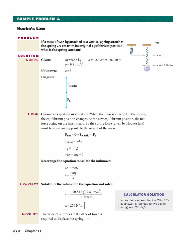
P R O B L E MIf a mass of 0.55 kg attached to a vertical spring stretchesthe spring 2.0 cm from its original equilibrium position,what is the spring constant?
S O L U T I O NGiven: m = 0.55 kg x = −2.0 cm = −0.020 m
g = 9.81 m/s2
Unknown: k = ?
Diagram:
Choose an equation or situation: When the mass is attached to the spring,
the equilibrium position changes. At the new equilibrium position, the net
force acting on the mass is zero. So the spring force (given by Hooke’s law)
must be equal and opposite to the weight of the mass.
Fnet = 0 = Felastic + Fg
Felastic = –kx
Fg = −mg
−kx − mg = 0
Rearrange the equation to isolate the unknown:
kx = −mg
k = −m
x
g
Substitute the values into the equation and solve:
k =
The value of k implies that 270 N of force is
required to displace the spring 1 m.
k = 270 N/m
−(0.55 kg)(9.81 m/s2)
−0.020 m
Fg
Felastic
1. DEFINE
2. PLAN
3. CALCULATE
4. EVALUATE
mx = −2.0 cm
x = 0
+x
CALCULATOR SOLUTION
The calculator answer for k is 269.775.This answer is rounded to two signifi-cant figures, 270 N/m.
A stretched or compressed spring has elastic potential energy
As you saw in the chapter “Work and Energy,” a stretched or compressed
spring stores elastic potential energy. To see how mechanical energy is con-
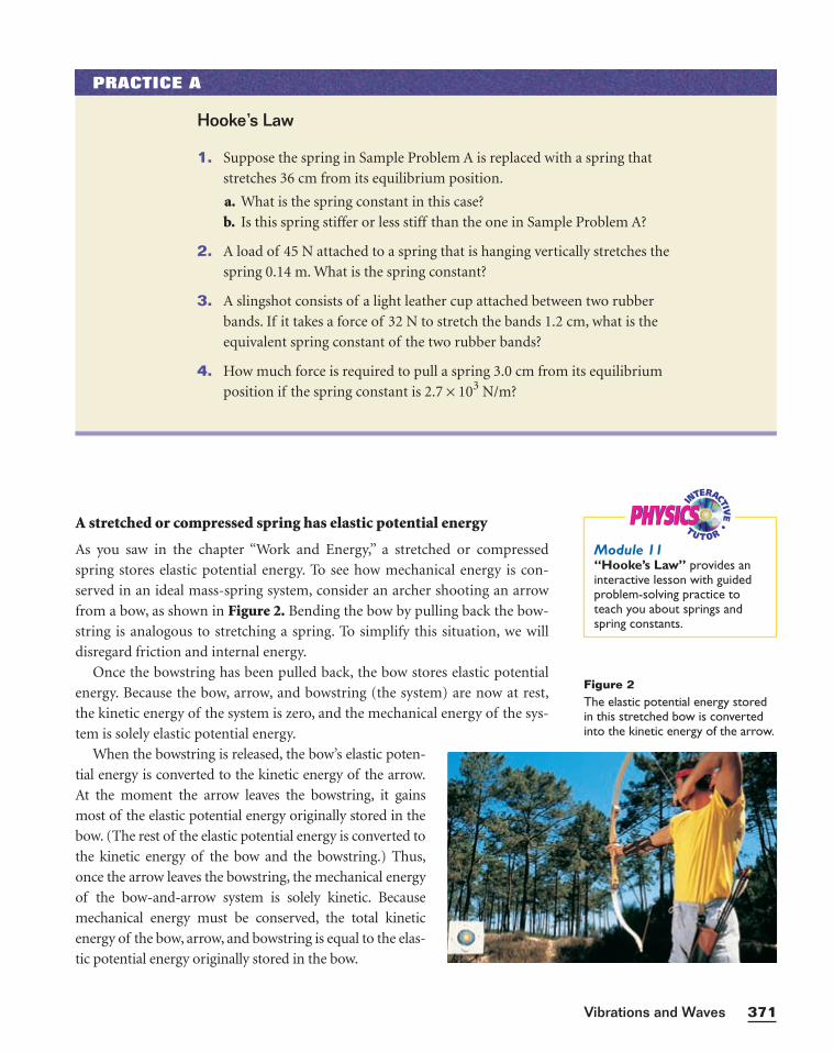
served in an ideal mass-spring system, consider an archer shooting an arrow
from a bow, as shown in Figure 2. Bending the bow by pulling back the bow-
string is analogous to stretching a spring. To simplify this situation, we will
disregard friction and internal energy.
Once the bowstring has been pulled back, the bow stores elastic potential
energy. Because the bow, arrow, and bowstring (the system) are now at rest,
the kinetic energy of the system is zero, and the mechanical energy of the sys-
tem is solely elastic potential energy.
When the bowstring is released, the bow’s elastic poten-
tial energy is converted to the kinetic energy of the arrow.
At the moment the arrow leaves the bowstring, it gains
most of the elastic potential energy originally stored in the
bow. (The rest of the elastic potential energy is converted to
the kinetic energy of the bow and the bowstring.) Thus,
once the arrow leaves the bowstring, the mechanical energy
of the bow-and-arrow system is solely kinetic. Because
mechanical energy must be conserved, the total kinetic
energy of the bow, arrow, and bowstring is equal to the elas-
tic potential energy originally stored in the bow.
371Vibrations and Waves
PRACTICE A
Hooke’s Law
1. Suppose the spring in Sample Problem A is replaced with a spring that
stretches 36 cm from its equilibrium position.
a. What is the spring constant in this case?
b. Is this spring stiffer or less stiff than the one in Sample Problem A?
2. A load of 45 N attached to a spring that is hanging vertically stretches the
spring 0.14 m. What is the spring constant?
3. A slingshot consists of a light leather cup attached between two rubber
bands. If it takes a force of 32 N to stretch the bands 1.2 cm, what is the
equivalent spring constant of the two rubber bands?
4. How much force is required to pull a spring 3.0 cm from its equilibrium
position if the spring constant is 2.7 × 10³ N/m?
Figure 2The elastic potential energy storedin this stretched bow is convertedinto the kinetic energy of the arrow.
PHYSICSPHYSICSModule 11“Hooke’s Law” provides aninteractive lesson with guidedproblem-solving practice toteach you about springs andspring constants.

THE INSIDE STORYON SHOCK ABSORBERS
Bumps in the road are certainly a nuisance, but with-out strategic use of damping devices, they could also
prove deadly. To control a car going110 km/h (70 mi/h), a driver needs all the
wheels on the ground. Bumps in theroad lift the wheels off the groundand rob the driver of control. A goodsolution is to fit the car with springsat each wheel. The springs absorb
energy as the wheelsrise over the bumpsand push thewheels back to thepavement to keepthe wheels on theroad. However,once set in motion,springs tend tocontinue to go up
and down in simpleharmonic motion. This affects the driver’s control ofthe car and can also be uncomfortable.
One way to cut down on unwanted vibrations is touse stiff springs that compress only a few centimetersunder thousands of newtons of force. Such springs havevery high spring constants and thus do not vibrate asfreely as softer springs with lower constants. However,
this solution reduces the driver’s ability to keep thecar’s wheels on the road.
To completely solve the problem, energy-absorbingdevices known as shock absorbers are placed parallel tothe springs in some automobiles, as shown in part (a) ofthe illustration below. Shock absorbers are fluid-filledtubes that turn the simple harmonic motion of thesprings into damped harmonic motion. In damped har-monic motion, each cycle of stretch and compression ofthe spring is much smaller than the previous cycle. Mod-ern auto suspensions are set up so that all of a spring’senergy is absorbed by the shock absorbers, eliminatingvibrations in just one up-and-down cycle. This keeps thecar from continually bouncing without sacrificing thespring’s ability to keep the wheels on the road.
Different spring constants and shock absorberdamping are combined to give a wide variety of roadresponses. For example, larger vehicles have heavy-dutyleaf springs made of stacks of steel strips, which have alarger spring constant than coil springs do. In this typeof suspension system, the shock absorber is perpendic-ular to the spring, as shown in part (b) of the illustra-tion. The stiffness of the spring can affect steeringresponse time, traction, and the general feel of the car.
As a result of the variety of combinations that arepossible, your driving experiences can range from theluxurious floating of a limousine to the bone-rattlingroad feel of a sports car.
Coil spring
Shock absorber
Shock absorber Leaf spring
(a) (b)
Chapter 11372
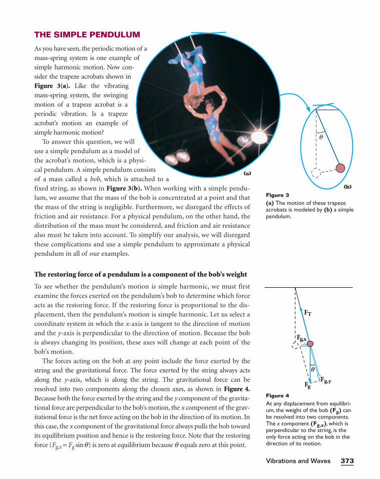
THE SIMPLE PENDULUM
As you have seen, the periodic motion of a
mass-spring system is one example of
simple harmonic motion. Now con-
sider the trapeze acrobats shown in
Figure 3(a). Like the vibrating
mass-spring system, the swinging
motion of a trapeze acrobat is a
periodic vibration. Is a trapeze
acrobat’s motion an example of
simple harmonic motion?
To answer this question, we will
use a simple pendulum as a model of
the acrobat’s motion, which is a physi-
cal pendulum. A simple pendulum consists
of a mass called a bob, which is attached to a
fixed string, as shown in Figure 3(b). When working with a simple pendu-
lum, we assume that the mass of the bob is concentrated at a point and that
the mass of the string is negligible. Furthermore, we disregard the effects of
friction and air resistance. For a physical pendulum, on the other hand, the
distribution of the mass must be considered, and friction and air resistance
also must be taken into account. To simplify our analysis, we will disregard
these complications and use a simple pendulum to approximate a physical
pendulum in all of our examples.
The restoring force of a pendulum is a component of the bob’s weight
To see whether the pendulum’s motion is simple harmonic, we must first
examine the forces exerted on the pendulum’s bob to determine which force
acts as the restoring force. If the restoring force is proportional to the dis-
placement, then the pendulum’s motion is simple harmonic. Let us select a
coordinate system in which the x-axis is tangent to the direction of motion
and the y-axis is perpendicular to the direction of motion. Because the bob
is always changing its position, these axes will change at each point of the
bob’s motion.
The forces acting on the bob at any point include the force exerted by the
string and the gravitational force. The force exerted by the string always acts
along the y-axis, which is along the string. The gravitational force can be
resolved into two components along the chosen axes, as shown in Figure 4.Because both the force exerted by the string and the y component of the gravita-
tional force are perpendicular to the bob’s motion, the x component of the grav-
itational force is the net force acting on the bob in the direction of its motion. In
this case, the x component of the gravitational force always pulls the bob toward
its equilibrium position and hence is the restoring force. Note that the restoring
force (Fg,x = Fg sinq) is zero at equilibrium because q equals zero at this point.
373Vibrations and Waves
Figure 3(a) The motion of these trapezeacrobats is modeled by (b) a simple pendulum.
Fg,x
Fg,y
FT
Fg
θ
Figure 4At any displacement from equilibri-um, the weight of the bob (Fg) canbe resolved into two components.The x component (Fg,x), which isperpendicular to the string, is theonly force acting on the bob in thedirection of its motion.
(a)
(b)
θ
For small angles, the pendulum’s motion is simple harmonic
As with a mass-spring system, the restoring force of a simple pendulum is not
constant. Instead, the magnitude of the restoring force varies with the bob’s dis-
tance from the equilibrium position. The magnitude of the restoring force is pro-
portional to sinq . When the maximum angle of displacement q is relatively small
(<15°), sinq is approximately equal to q in radians. As a result, the restoring force
is very nearly proportional to the displacement and the pendulum’s motion is an
excellent approximation of simple harmonic motion. We will assume small angles
of displacement unless otherwise noted.
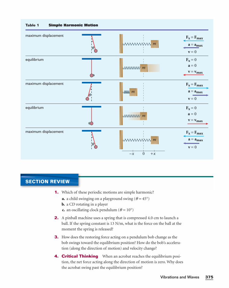
Because a simple pendulum vibrates with simple harmonic motion,
many of our earlier conclusions for a mass-spring system apply here. At
maximum displacement, the restoring force and acceleration reach a maxi-
mum while the speed becomes zero. Conversely, at equilibrium, the restor-
ing force and acceleration become zero and speed reaches a maximum.
Table 1 on the following page illustrates the analogy between a simple pen-
dulum and a mass-spring system.
Gravitational potential increases as a pendulum’s displacement increases
As with the mass-spring system, the mechanical energy of a simple pendulum
is conserved in an ideal (frictionless) system. However, the spring’s potential
energy is elastic, while the pendulum’s potential energy is gravitational. We
define the gravitational potential energy of a pendulum to be zero when it is
at the lowest point of its swing.
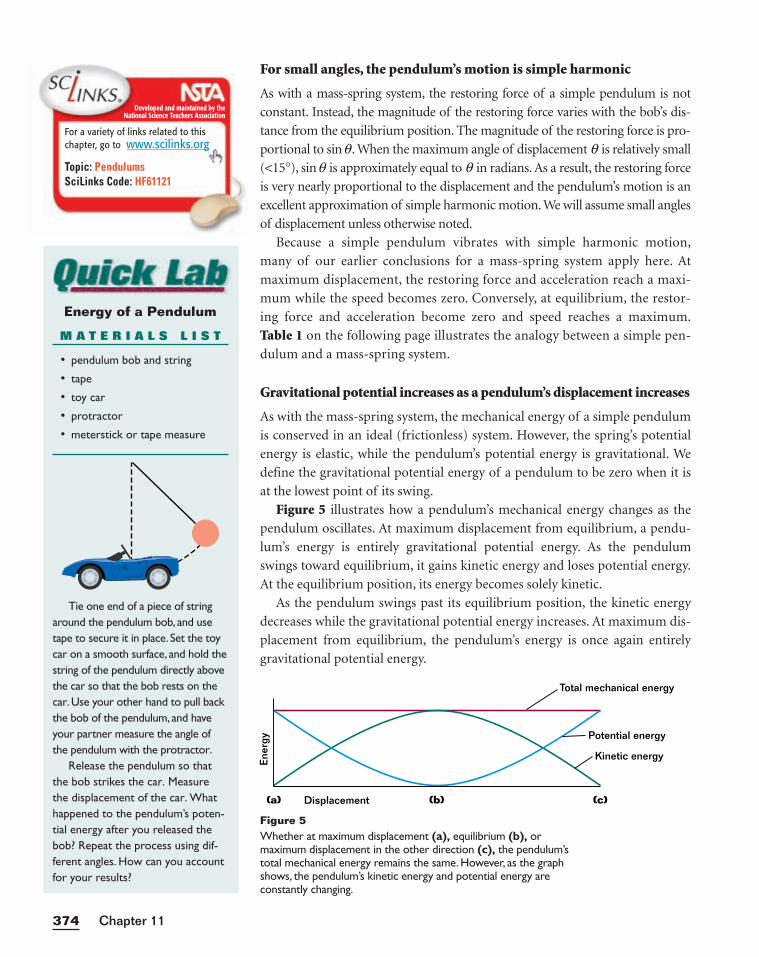
Figure 5 illustrates how a pendulum’s mechanical energy changes as the
pendulum oscillates. At maximum displacement from equilibrium, a pendu-
lum’s energy is entirely gravitational potential energy. As the pendulum
swings toward equilibrium, it gains kinetic energy and loses potential energy.
At the equilibrium position, its energy becomes solely kinetic.
As the pendulum swings past its equilibrium position, the kinetic energy
decreases while the gravitational potential energy increases. At maximum dis-
placement from equilibrium, the pendulum’s energy is once again entirely
gravitational potential energy.
Chapter 11374
Ener
gy
Total mechanical energy
Displacement(a) (b) (c)
Potential energy
Kinetic energy
Figure 5Whether at maximum displacement (a), equilibrium (b), or maximum displacement in the other direction (c), the pendulum’stotal mechanical energy remains the same. However, as the graphshows, the pendulum’s kinetic energy and potential energy are constantly changing.
Energy of a Pendulum
M A T E R I A L S L I S T
• pendulum bob and string
• tape
• toy car
• protractor
• meterstick or tape measure
Tie one end of a piece of stringaround the pendulum bob, and usetape to secure it in place. Set the toycar on a smooth surface, and hold thestring of the pendulum directly abovethe car so that the bob rests on thecar.Use your other hand to pull backthe bob of the pendulum, and haveyour partner measure the angle ofthe pendulum with the protractor.
Release the pendulum so thatthe bob strikes the car. Measurethe displacement of the car. Whathappened to the pendulum’s poten-tial energy after you released thebob? Repeat the process using dif-ferent angles. How can you accountfor your results?
Developed and maintained by theNational Science Teachers Association
For a variety of links related to thischapter, go to www.scilinks.org
Topic: PendulumsSciLinks Code: HF61121
375Vibrations and Waves
Table 1 Simple Harmonic Motion
maximum displacement
equilibrium
maximum displacement
equilibrium
maximum displacement
θm
Fx = Fmax
a = amax
v = 0
v = vmax
Fx = 0
a = 0
θ
Fx = Fmax
a = amax
v = 0
v = vmax
Fx = 0
a = 0
θ
Fx = Fmax
a = amax
v = 0
m
m
m
x0x
m
+–
SECTION REVIEW
1. Which of these periodic motions are simple harmonic?
a. a child swinging on a playground swing (q = 45°)
b. a CD rotating in a player
c. an oscillating clock pendulum (q = 10°)
2. A pinball machine uses a spring that is compressed 4.0 cm to launch a
ball. If the spring constant is 13 N/m, what is the force on the ball at the
moment the spring is released?
3. How does the restoring force acting on a pendulum bob change as the
bob swings toward the equilibrium position? How do the bob’s accelera-
tion (along the direction of motion) and velocity change?
4. Critical Thinking When an acrobat reaches the equilibrium posi-
tion, the net force acting along the direction of motion is zero. Why does
the acrobat swing past the equilibrium position?
amplitude
the maximum displacement fromequilibrium
period
the time that it takes a completecycle to occur
frequency
the number of cycles or vibra-tions per unit of time
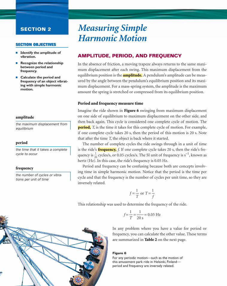
Figure 6For any periodic motion—such as the motion ofthis amusement park ride in Helsinki, Finland—period and frequency are inversely related.
Measuring Simple Harmonic Motion
SECTION 2
AMPLITUDE, PERIOD, AND FREQUENCY
In the absence of friction, a moving trapeze always returns to the same maxi-
mum displacement after each swing. This maximum displacement from the
equilibrium position is the A pendulum’s amplitude can be meas-
ured by the angle between the pendulum’s equilibrium position and its maxi-
mum displacement. For a mass-spring system, the amplitude is the maximum
amount the spring is stretched or compressed from its equilibrium position.
Period and frequency measure time
Imagine the ride shown in Figure 6 swinging from maximum displacement
on one side of equilibrium to maximum displacement on the other side, and
then back again. This cycle is considered one complete cycle of motion. The
T, is the time it takes for this complete cycle of motion. For example,
if one complete cycle takes 20 s, then the period of this motion is 20 s. Note
that after the time T, the object is back where it started.
The number of complete cycles the ride swings through in a unit of time
is the ride’s f. If one complete cycle takes 20 s, then the ride’s fre-
quency is 2
1
0 cycles/s, or 0.05 cycles/s. The SI unit of frequency is s–1, known as
hertz (Hz). In this case, the ride’s frequency is 0.05 Hz.
Period and frequency can be confusing because both are concepts involv-
ing time in simple harmonic motion. Notice that the period is the time per
cycle and that the frequency is the number of cycles per unit time, so they are
inversely related.
f = T
1 or T =
1
f
This relationship was used to determine the frequency of the ride.
f = T
1 =
20
1
s = 0.05 Hz
frequency,
period,
amplitude.
SECTION OBJECTIVES
■ Identify the amplitude ofvibration.
■ Recognize the relationshipbetween period and frequency.
■ Calculate the period and frequency of an object vibrat-ing with simple harmonicmotion.
In any problem where you have a value for period or
frequency, you can calculate the other value. These terms
are summarized in Table 2 on the next page.
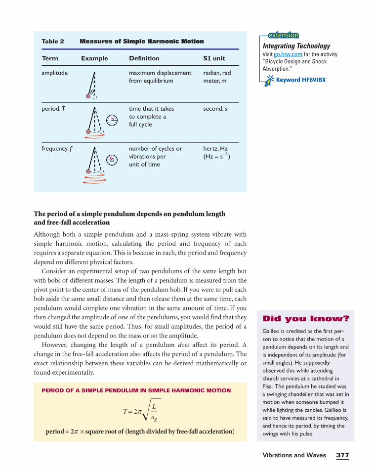
Table 2 Measures of Simple Harmonic Motion
Term Example Definition SI unit
amplitude maximum displacement radian, radfrom equilibrium meter, m
period, T time that it takes second, sto complete afull cycle
frequency, f number of cycles or hertz, Hzvibrations per (Hz = s− 1)unit of time
θ
The period of a simple pendulum depends on pendulum length and free-fall acceleration
Although both a simple pendulum and a mass-spring system vibrate with
simple harmonic motion, calculating the period and frequency of each
requires a separate equation. This is because in each, the period and frequency
depend on different physical factors.
Consider an experimental setup of two pendulums of the same length but
with bobs of different masses. The length of a pendulum is measured from the
pivot point to the center of mass of the pendulum bob. If you were to pull each
bob aside the same small distance and then release them at the same time, each
pendulum would complete one vibration in the same amount of time. If you
then changed the amplitude of one of the pendulums, you would find that they
would still have the same period. Thus, for small amplitudes, the period of a
pendulum does not depend on the mass or on the amplitude.
However, changing the length of a pendulum does affect its period. A
change in the free-fall acceleration also affects the period of a pendulum. The
exact relationship between these variables can be derived mathematically or
found experimentally.
PERIOD OF A SIMPLE PENDULUM IN SIMPLE HARMONIC MOTION
T = 2p��aLg
period = 2p × square root of (length divided by free-fall acceleration)
377Vibrations and Waves
Galileo is credited as the first per-son to notice that the motion of apendulum depends on its length andis independent of its amplitude (forsmall angles). He supposedlyobserved this while attendingchurch services at a cathedral inPisa. The pendulum he studied was a swinging chandelier that was set inmotion when someone bumped itwhile lighting the candles. Galileo issaid to have measured its frequency,and hence its period, by timing theswings with his pulse.
Did you know?
Integrating TechnologyVisit go.hrw.com for the activity“Bicycle Design and Shock Absorption.”
Keyword HF6VIBX
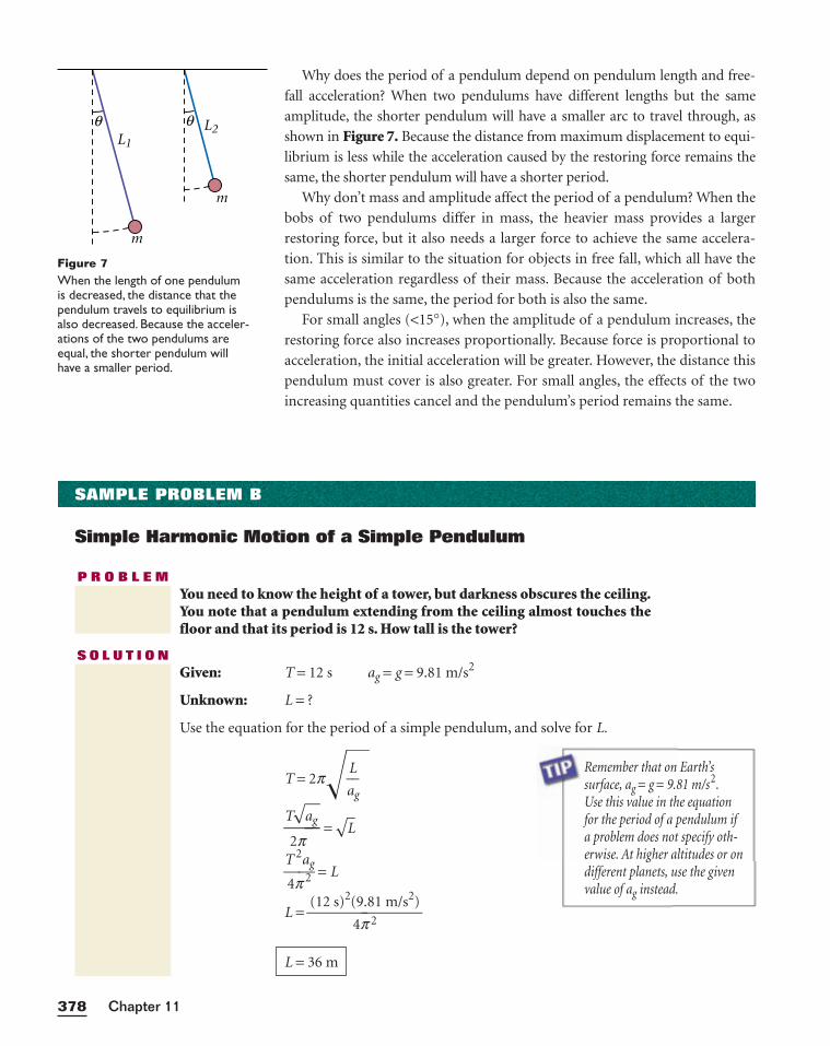
Why does the period of a pendulum depend on pendulum length and free-
fall acceleration? When two pendulums have different lengths but the same
amplitude, the shorter pendulum will have a smaller arc to travel through, as
shown in Figure 7. Because the distance from maximum displacement to equi-
librium is less while the acceleration caused by the restoring force remains the
same, the shorter pendulum will have a shorter period.
Why don’t mass and amplitude affect the period of a pendulum? When the
bobs of two pendulums differ in mass, the heavier mass provides a larger
restoring force, but it also needs a larger force to achieve the same accelera-
tion. This is similar to the situation for objects in free fall, which all have the
same acceleration regardless of their mass. Because the acceleration of both
pendulums is the same, the period for both is also the same.
For small angles (<15°), when the amplitude of a pendulum increases, the
restoring force also increases proportionally. Because force is proportional to
acceleration, the initial acceleration will be greater. However, the distance this
pendulum must cover is also greater. For small angles, the effects of the two
increasing quantities cancel and the pendulum’s period remains the same.
Chapter 11378
L1
L2θ θ
m
m
Figure 7When the length of one pendulumis decreased, the distance that thependulum travels to equilibrium isalso decreased. Because the acceler-ations of the two pendulums areequal, the shorter pendulum willhave a smaller period.
SAMPLE PROBLEM B
Simple Harmonic Motion of a Simple Pendulum
P R O B L E MYou need to know the height of a tower, but darkness obscures the ceiling.You note that a pendulum extending from the ceiling almost touches thefloor and that its period is 12 s. How tall is the tower?
S O L U T I O NGiven: T = 12 s ag = g = 9.81 m/s2
Unknown: L = ?
Use the equation for the period of a simple pendulum, and solve for L.
T = 2p��aLg
T
2
√
p
ag� =
√L�
T
4p
2a2g = L
L = (12 s)2(
4
9
p.8
2
1 m/s2)
L = 36 m
Remember that on Earth’s surface, ag = g = 9.81 m/s2.Use this value in the equationfor the period of a pendulum ifa problem does not specify oth-erwise. At higher altitudes or ondifferent planets, use the givenvalue of ag instead.
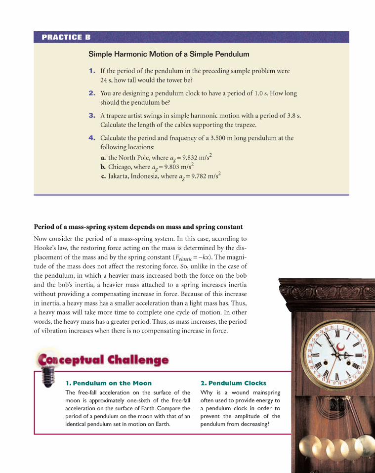
1. Pendulum on the Moon
The free-fall acceleration on the surface of themoon is approximately one-sixth of the free-fallacceleration on the surface of Earth. Compare theperiod of a pendulum on the moon with that of anidentical pendulum set in motion on Earth.
2. Pendulum Clocks
Why is a wound mainspringoften used to provide energy toa pendulum clock in order toprevent the amplitude of thependulum from decreasing?
Period of a mass-spring system depends on mass and spring constant
Now consider the period of a mass-spring system. In this case, according to
Hooke’s law, the restoring force acting on the mass is determined by the dis-
placement of the mass and by the spring constant (Felastic = –kx). The magni-
tude of the mass does not affect the restoring force. So, unlike in the case of
the pendulum, in which a heavier mass increased both the force on the bob
and the bob’s inertia, a heavier mass attached to a spring increases inertia
without providing a compensating increase in force. Because of this increase
in inertia, a heavy mass has a smaller acceleration than a light mass has. Thus,
a heavy mass will take more time to complete one cycle of motion. In other
words, the heavy mass has a greater period. Thus, as mass increases, the period
of vibration increases when there is no compensating increase in force.
PRACTICE B
Simple Harmonic Motion of a Simple Pendulum
1. If the period of the pendulum in the preceding sample problem were
24 s, how tall would the tower be?
2. You are designing a pendulum clock to have a period of 1.0 s. How long
should the pendulum be?
3. A trapeze artist swings in simple harmonic motion with a period of 3.8 s.
Calculate the length of the cables supporting the trapeze.
4. Calculate the period and frequency of a 3.500 m long pendulum at the
following locations:
a. the North Pole, where ag = 9.832 m/s2
b. Chicago, where ag = 9.803 m/s2
c. Jakarta, Indonesia, where ag = 9.782 m/s2
The greater the spring constant (k), the stiffer the spring; hence a greater force is
required to stretch or compress the spring. When force is greater, acceleration is
greater and the amount of time required for a single cycle should decrease (assum-
ing that the amplitude remains constant). Thus, for a given amplitude, a stiffer
spring will take less time to complete one cycle of motion than one that is less stiff.
As with the pendulum, the equation for the period of a mass-spring sys-
tem can be derived mathematically or found experimentally.
Note that changing the amplitude of the vibration does not affect the
period. This statement is true only for systems and circumstances in which
the spring obeys Hooke’s law.
PERIOD OF A MASS-SPRING SYSTEM IN SIMPLE HARMONIC MOTION
T = 2p�m
k���period = 2p × square root of (mass divided by spring constant)
Chapter 11380
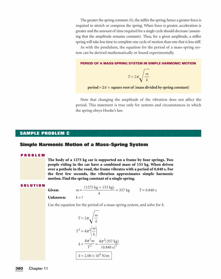
SAMPLE PROBLEM C
Simple Harmonic Motion of a Mass-Spring System
P R O B L E MThe body of a 1275 kg car is supported on a frame by four springs. Twopeople riding in the car have a combined mass of 153 kg. When drivenover a pothole in the road, the frame vibrates with a period of 0.840 s. Forthe first few seconds, the vibration approximates simple harmonicmotion. Find the spring constant of a single spring.
S O L U T I O NGiven: m =
(1275 kg
4
+ 153 kg) = 357 kg T = 0.840 s
Unknown: k = ?
Use the equation for the period of a mass-spring system, and solve for k.
T = 2p�m
k��
T2 = 4p2�m
k�
k = =
k = 2.00 × 10⁴ N/m
4p 2(357 kg)(0.840 s)2
4p 2m
T2
381Vibrations and Waves
PRACTICE C
Simple Harmonic Motion of a Mass-Spring System
1. A mass of 0.30 kg is attached to a spring and is set into vibration with a
period of 0.24 s. What is the spring constant of the spring?
2. When a mass of 25 g is attached to a certain spring, it makes 20 complete
vibrations in 4.0 s. What is the spring constant of the spring?
3. A 125 N object vibrates with a period of 3.56 s when hanging from a
spring. What is the spring constant of the spring?
4. When two more people get into the car described in Sample Problem C,
the total mass of all four occupants of the car becomes 255 kg. Now what
is the period of vibration of the car when it is driven over a pothole in
the road?
5. A spring of spring constant 30.0 N/m is attached to different masses, and
the system is set in motion. Find the period and frequency of vibration
for masses of the following magnitudes:
a. 2.3 kg
b. 15 g
c. 1.9 kg
SECTION REVIEW
1. The reading on a metronome indicates the number of oscillations per
minute. What are the frequency and period of the metronome’s vibra-
tion when the metronome is set at 180?
2. A child swings on a playground swing with a 2.5 m long chain.
a. What is the period of the child’s motion?
b. What is the frequency of vibration?
3. A 0.75 kg mass attached to a vertical spring stretches the spring 0.30 m.
a. What is the spring constant?
b. The mass-spring system is now placed on a horizontal surface and set
vibrating. What is the period of the vibration?
4. Critical Thinking Two mass-spring systems vibrate with simple
harmonic motion. If the spring constants are equal and the mass of one
system is twice that of the other, which system has a greater period?
Properties of WavesSECTION 3
WAVE MOTION
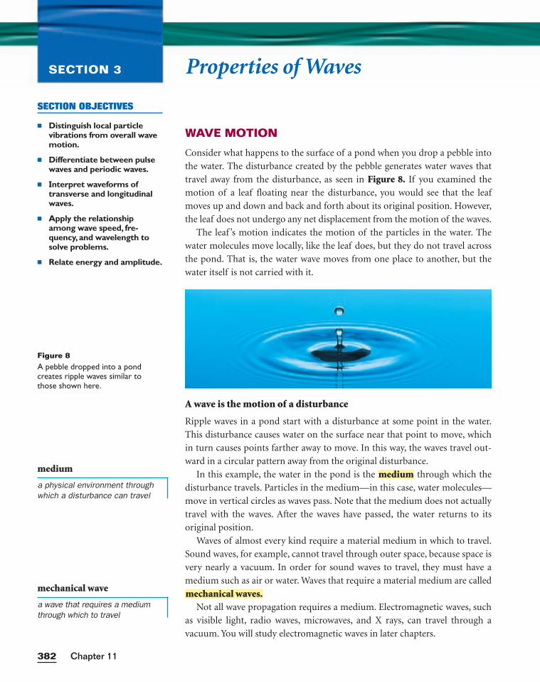
Consider what happens to the surface of a pond when you drop a pebble into
the water. The disturbance created by the pebble generates water waves that
travel away from the disturbance, as seen in Figure 8. If you examined the
motion of a leaf floating near the disturbance, you would see that the leaf
moves up and down and back and forth about its original position. However,
the leaf does not undergo any net displacement from the motion of the waves.
The leaf ’s motion indicates the motion of the particles in the water. The
water molecules move locally, like the leaf does, but they do not travel across
the pond. That is, the water wave moves from one place to another, but the
water itself is not carried with it.
A wave is the motion of a disturbance
Ripple waves in a pond start with a disturbance at some point in the water.
This disturbance causes water on the surface near that point to move, which
in turn causes points farther away to move. In this way, the waves travel out-
ward in a circular pattern away from the original disturbance.
In this example, the water in the pond is the through which the
disturbance travels. Particles in the medium—in this case, water molecules—
move in vertical circles as waves pass. Note that the medium does not actually
travel with the waves. After the waves have passed, the water returns to its
original position.
Waves of almost every kind require a material medium in which to travel.
Sound waves, for example, cannot travel through outer space, because space is
very nearly a vacuum. In order for sound waves to travel, they must have a
medium such as air or water. Waves that require a material medium are called
Not all wave propagation requires a medium. Electromagnetic waves, such
as visible light, radio waves, microwaves, and X rays, can travel through a
vacuum. You will study electromagnetic waves in later chapters.
mechanical waves.
medium
Chapter 11382
SECTION OBJECTIVES
■ Distinguish local particlevibrations from overall wavemotion.
■ Differentiate between pulsewaves and periodic waves.
■ Interpret waveforms oftransverse and longitudinalwaves.
■ Apply the relationshipamong wave speed, fre-quency, and wavelength tosolve problems.
■ Relate energy and amplitude.
Figure 8A pebble dropped into a pondcreates ripple waves similar tothose shown here.
medium
a physical environment throughwhich a disturbance can travel
mechanical wave
a wave that requires a mediumthrough which to travel
WAVE TYPES
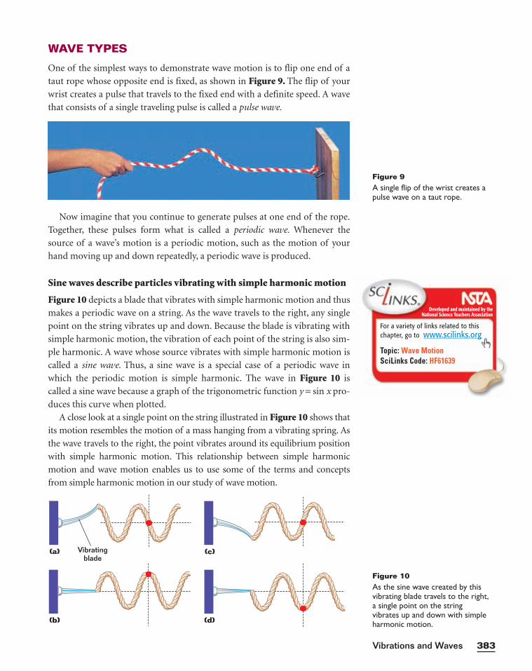
One of the simplest ways to demonstrate wave motion is to flip one end of a
taut rope whose opposite end is fixed, as shown in Figure 9. The flip of your
wrist creates a pulse that travels to the fixed end with a definite speed. A wave
that consists of a single traveling pulse is called a pulse wave.
Now imagine that you continue to generate pulses at one end of the rope.
Together, these pulses form what is called a periodic wave. Whenever the
source of a wave’s motion is a periodic motion, such as the motion of your
hand moving up and down repeatedly, a periodic wave is produced.
Sine waves describe particles vibrating with simple harmonic motion
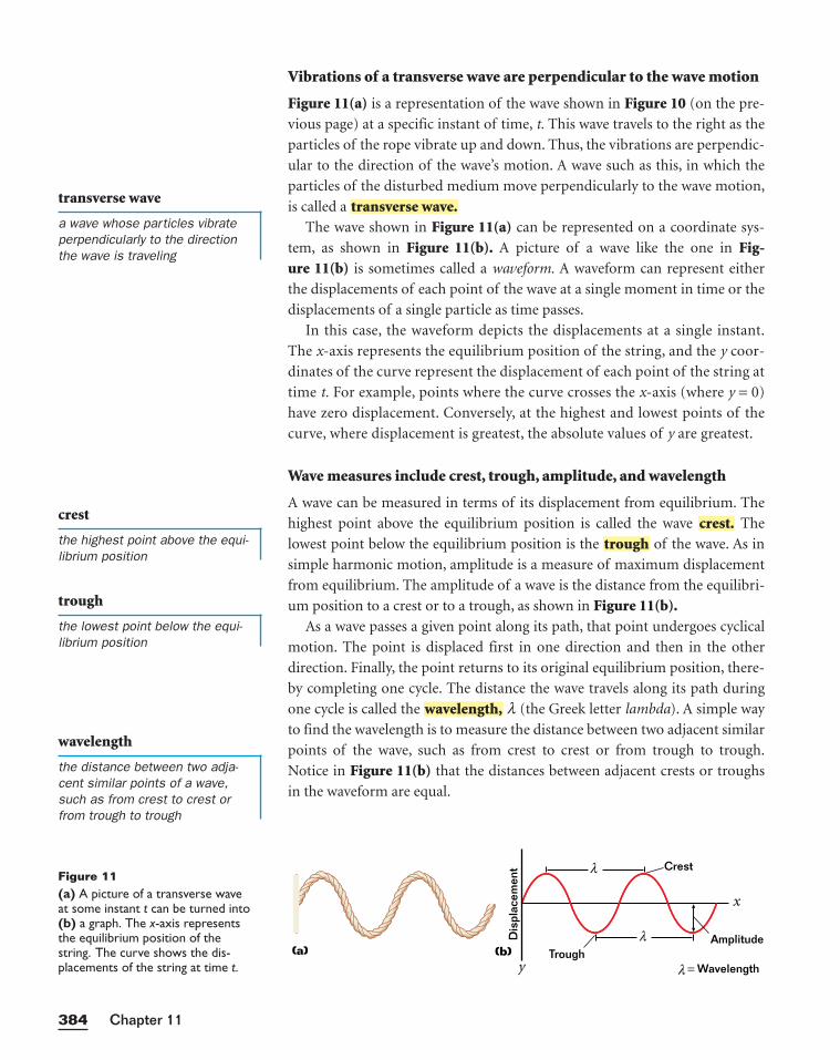
Figure 10 depicts a blade that vibrates with simple harmonic motion and thus
makes a periodic wave on a string. As the wave travels to the right, any single
point on the string vibrates up and down. Because the blade is vibrating with
simple harmonic motion, the vibration of each point of the string is also sim-
ple harmonic. A wave whose source vibrates with simple harmonic motion is
called a sine wave. Thus, a sine wave is a special case of a periodic wave in
which the periodic motion is simple harmonic. The wave in Figure 10 is
called a sine wave because a graph of the trigonometric function y = sin x pro-
duces this curve when plotted.
A close look at a single point on the string illustrated in Figure 10 shows that
its motion resembles the motion of a mass hanging from a vibrating spring. As
the wave travels to the right, the point vibrates around its equilibrium position
with simple harmonic motion. This relationship between simple harmonic
motion and wave motion enables us to use some of the terms and concepts
from simple harmonic motion in our study of wave motion.
383Vibrations and Waves
(a) (c)
(b) (d)
Vibratingblade
Figure 10As the sine wave created by thisvibrating blade travels to the right,a single point on the string vibrates up and down with simpleharmonic motion.
Figure 9A single flip of the wrist creates apulse wave on a taut rope.
Developed and maintained by theNational Science Teachers Association
For a variety of links related to thischapter, go to www.scilinks.org
Topic: Wave MotionSciLinks Code: HF61639
Chapter 11384
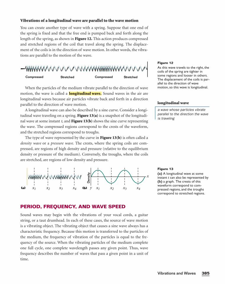
Figure 11(a) A picture of a transverse waveat some instant t can be turned into(b) a graph. The x-axis representsthe equilibrium position of thestring. The curve shows the dis-placements of the string at time t.
crest
the highest point above the equi-librium position
transverse wave
a wave whose particles vibrateperpendicularly to the directionthe wave is traveling
trough
the lowest point below the equi-librium position
wavelength
the distance between two adja-cent similar points of a wave,such as from crest to crest orfrom trough to trough
Dis
plac
emen
t
= Wavelength
x
y
Crest
TroughAmplitude
(a) (b)
λ
λ
λ
Vibrations of a transverse wave are perpendicular to the wave motion
Figure 11(a) is a representation of the wave shown in Figure 10 (on the pre-
vious page) at a specific instant of time, t. This wave travels to the right as the
particles of the rope vibrate up and down. Thus, the vibrations are perpendic-
ular to the direction of the wave’s motion. A wave such as this, in which the
particles of the disturbed medium move perpendicularly to the wave motion,
is called a
The wave shown in Figure 11(a) can be represented on a coordinate sys-
tem, as shown in Figure 11(b). A picture of a wave like the one in Fig-ure 11(b) is sometimes called a waveform. A waveform can represent either
the displacements of each point of the wave at a single moment in time or the
displacements of a single particle as time passes.
In this case, the waveform depicts the displacements at a single instant.
The x-axis represents the equilibrium position of the string, and the y coor-
dinates of the curve represent the displacement of each point of the string at
time t. For example, points where the curve crosses the x-axis (where y = 0)
have zero displacement. Conversely, at the highest and lowest points of the
curve, where displacement is greatest, the absolute values of y are greatest.
Wave measures include crest, trough, amplitude, and wavelength
A wave can be measured in terms of its displacement from equilibrium. The
highest point above the equilibrium position is called the wave The
lowest point below the equilibrium position is the of the wave. As in
simple harmonic motion, amplitude is a measure of maximum displacement
from equilibrium. The amplitude of a wave is the distance from the equilibri-
um position to a crest or to a trough, as shown in Figure 11(b).As a wave passes a given point along its path, that point undergoes cyclical
motion. The point is displaced first in one direction and then in the other
direction. Finally, the point returns to its original equilibrium position, there-
by completing one cycle. The distance the wave travels along its path during
one cycle is called the l (the Greek letter lambda). A simple way
to find the wavelength is to measure the distance between two adjacent similar
points of the wave, such as from crest to crest or from trough to trough.
Notice in Figure 11(b) that the distances between adjacent crests or troughs
in the waveform are equal.
wavelength,
troughcrest.
transverse wave.
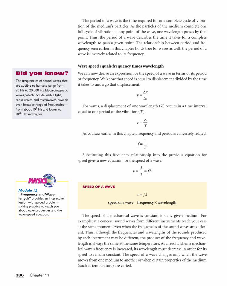
Vibrations of a longitudinal wave are parallel to the wave motion
You can create another type of wave with a spring. Suppose that one end of
the spring is fixed and that the free end is pumped back and forth along the
length of the spring, as shown in Figure 12. This action produces compressed
and stretched regions of the coil that travel along the spring. The displace-
ment of the coils is in the direction of wave motion. In other words, the vibra-
tions are parallel to the motion of the wave.
When the particles of the medium vibrate parallel to the direction of wave
motion, the wave is called a Sound waves in the air are
longitudinal waves because air particles vibrate back and forth in a direction
parallel to the direction of wave motion.
A longitudinal wave can also be described by a sine curve. Consider a longi-
tudinal wave traveling on a spring. Figure 13(a) is a snapshot of the longitudi-
nal wave at some instant t, and Figure 13(b) shows the sine curve representing
the wave. The compressed regions correspond to the crests of the waveform,
and the stretched regions correspond to troughs.
The type of wave represented by the curve in Figure 13(b) is often called a
density wave or a pressure wave. The crests, where the spring coils are com-
pressed, are regions of high density and pressure (relative to the equilibrium
density or pressure of the medium). Conversely, the troughs, where the coils
are stretched, are regions of low density and pressure.
longitudinal wave.
PERIOD, FREQUENCY, AND WAVE SPEED
Sound waves may begin with the vibrations of your vocal cords, a guitar
string, or a taut drumhead. In each of these cases, the source of wave motion
is a vibrating object. The vibrating object that causes a sine wave always has a
characteristic frequency. Because this motion is transferred to the particles of
the medium, the frequency of vibration of the particles is equal to the fre-
quency of the source. When the vibrating particles of the medium complete
one full cycle, one complete wavelength passes any given point. Thus, wave
frequency describes the number of waves that pass a given point in a unit of
time.
385Vibrations and Waves
Compressed CompressedStretched Stretched
Figure 12As this wave travels to the right, thecoils of the spring are tighter insome regions and looser in others.The displacement of the coils is par-allel to the direction of wavemotion, so this wave is longitudinal.
longitudinal wave
a wave whose particles vibrateparallel to the direction the waveis traveling
(a) (b)
Den
sity
x
yx1 x2 x3 x4 x1 x2 x3 x4
Figure 13(a) A longitudinal wave at someinstant t can also be represented by(b) a graph. The crests of thiswaveform correspond to com-pressed regions, and the troughscorrespond to stretched regions.
The period of a wave is the time required for one complete cycle of vibra-
tion of the medium’s particles. As the particles of the medium complete one
full cycle of vibration at any point of the wave, one wavelength passes by that
point. Thus, the period of a wave describes the time it takes for a complete
wavelength to pass a given point. The relationship between period and fre-
quency seen earlier in this chapter holds true for waves as well; the period of a
wave is inversely related to its frequency.
Wave speed equals frequency times wavelength
We can now derive an expression for the speed of a wave in terms of its period
or frequency. We know that speed is equal to displacement divided by the time
it takes to undergo that displacement.
v = ∆∆
x
t
For waves, a displacement of one wavelength (l) occurs in a time interval
equal to one period of the vibration (T ).
v = T
l
As you saw earlier in this chapter, frequency and period are inversely related.
f = T
1
Substituting this frequency relationship into the previous equation for
speed gives a new equation for the speed of a wave.
v = T
l = fl
The speed of a mechanical wave is constant for any given medium. For
example, at a concert, sound waves from different instruments reach your ears
at the same moment, even when the frequencies of the sound waves are differ-
ent. Thus, although the frequencies and wavelengths of the sounds produced
by each instrument may be different, the product of the frequency and wave-
length is always the same at the same temperature. As a result, when a mechan-
ical wave’s frequency is increased, its wavelength must decrease in order for its
speed to remain constant. The speed of a wave changes only when the wave
moves from one medium to another or when certain properties of the medium
(such as temperature) are varied.
SPEED OF A WAVE
v = fl
speed of a wave = frequency × wavelength
Chapter 11386
The frequencies of sound waves thatare audible to humans range from20 Hz to 20 000 Hz. Electromagneticwaves, which include visible light,radio waves, and microwaves, have aneven broader range of frequencies—from about 104 Hz and lower to1025 Hz and higher.
Did you know?
PHYSICSPHYSICSModule 12“Frequency and Wave-length” provides an interactivelesson with guided problem-solving practice to teach youabout wave properties and thewave-speed equation.
387Vibrations and Waves
SAMPLE PROBLEM D
Wave Speed
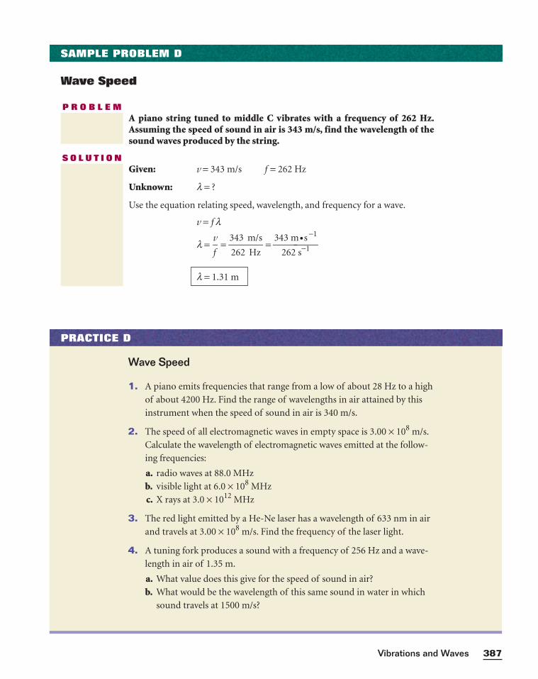
P R O B L E MA piano string tuned to middle C vibrates with a frequency of 262 Hz.Assuming the speed of sound in air is 343 m/s, find the wavelength of thesound waves produced by the string.
S O L U T I O NGiven: v = 343 m/s f = 262 Hz
Unknown: l = ?
Use the equation relating speed, wavelength, and frequency for a wave.
v = f l
l = ⎯f
v⎯ = ⎯
3
2
4
6
3
2
m
H
/
z
s⎯ = ⎯
34
2
3
6
m
2 s
•−s1
−1
⎯
l = 1.31 m
PRACTICE D
Wave Speed
1. A piano emits frequencies that range from a low of about 28 Hz to a high
of about 4200 Hz. Find the range of wavelengths in air attained by this
instrument when the speed of sound in air is 340 m/s.
2. The speed of all electromagnetic waves in empty space is 3.00 × 10⁸ m/s.
Calculate the wavelength of electromagnetic waves emitted at the follow-
ing frequencies:
a. radio waves at 88.0 MHz
b. visible light at 6.0 × 10⁸ MHz
c. X rays at 3.0 × 10¹² MHz
3. The red light emitted by a He-Ne laser has a wavelength of 633 nm in air
and travels at 3.00 × 10⁸ m/s. Find the frequency of the laser light.
4. A tuning fork produces a sound with a frequency of 256 Hz and a wave-
length in air of 1.35 m.
a. What value does this give for the speed of sound in air?
b. What would be the wavelength of this same sound in water in which
sound travels at 1500 m/s?
Waves transfer energy
When a pebble is dropped into a pond, the water wave that is produced carries
a certain amount of energy. As the wave spreads to other parts of the pond,
the energy likewise moves across the pond. Thus, the wave transfers energy
from one place in the pond to another while the water remains in essentially
the same place. In other words, waves transfer energy by the vibration of mat-
ter rather than by the transfer of matter itself. For this reason, waves are often
able to transport energy efficiently.
The rate at which a wave transfers energy depends on the amplitude at
which the particles of the medium are vibrating. The greater the amplitude,
the more energy a wave carries in a given time interval. For a mechanical
wave, the energy transferred is proportional to the square of the wave’s ampli-
tude. When the amplitude of a mechanical wave is doubled, the energy it car-
ries in a given time interval increases by a factor of four. Conversely, when the
amplitude is halved, the energy decreases by a factor of four.
As with a mass-spring system or a simple pendulum, the amplitude of a
wave gradually diminishes over time as its energy is dissipated. This effect,
called damping, is usually minimal over relatively short distances. For simplic-
ity, we have disregarded damping in our analysis of wave motions.
Chapter 11388
SECTION REVIEW
1. As waves pass by a duck floating on a lake, the duck bobs up and down
but remains in essentially one place. Explain why the duck is not carried
along by the wave motion.
2. Sketch each of the following waves that are on a spring that is attached to
a wall at one end:
a. a pulse wave that is longitudinal
b. a periodic wave that is longitudinal
c. a pulse wave that is transverse
d. a periodic wave that is transverse
3. Draw a graph for each of the waves described in items (b) and (d) above,
and label the y-axis of each graph with the appropriate variable. Label
the following on each graph: crest, trough, wavelength, and amplitude.
4. If the amplitude of a sound wave is increased by a factor of four, how does
the energy carried by the sound wave in a given time interval change?
5. The smallest insects that a bat can detect are approximately the size of
one wavelength of the sound the bat makes. What is the minimum
frequency of sound waves required for the bat to detect an insect that
is 0.57 cm long? (Assume the speed of sound is 340 m/s.)
Integrating Earth ScienceVisit go.hrw.com for the activity“Earthquake Waves.”
Keyword HF6VIBX
SECTION OBJECTIVES
■ Apply the superposition principle.
■ Differentiate between con-structive and destructiveinterference.
■ Predict when a reflectedwave will be inverted.
■ Predict whether specific trav-eling waves will produce astanding wave.
■ Identify nodes and antinodesof a standing wave.
389Vibrations and Waves
Wave Interactions SECTION 4
WAVE INTERFERENCE
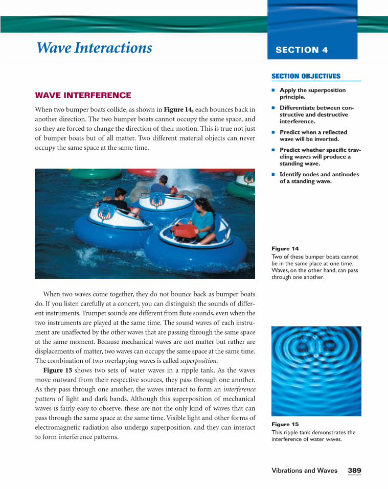
When two bumper boats collide, as shown in Figure 14, each bounces back in
another direction. The two bumper boats cannot occupy the same space, and
so they are forced to change the direction of their motion. This is true not just
of bumper boats but of all matter. Two different material objects can never
occupy the same space at the same time.
When two waves come together, they do not bounce back as bumper boats
do. If you listen carefully at a concert, you can distinguish the sounds of differ-
ent instruments. Trumpet sounds are different from flute sounds, even when the
two instruments are played at the same time. The sound waves of each instru-
ment are unaffected by the other waves that are passing through the same space
at the same moment. Because mechanical waves are not matter but rather are
displacements of matter, two waves can occupy the same space at the same time.
The combination of two overlapping waves is called superposition.
Figure 15 shows two sets of water waves in a ripple tank. As the waves
move outward from their respective sources, they pass through one another.
As they pass through one another, the waves interact to form an interference
pattern of light and dark bands. Although this superposition of mechanical
waves is fairly easy to observe, these are not the only kind of waves that can
pass through the same space at the same time. Visible light and other forms of
electromagnetic radiation also undergo superposition, and they can interact
to form interference patterns.
Figure 14Two of these bumper boats cannotbe in the same place at one time.Waves, on the other hand, can passthrough one another.
Figure 15This ripple tank demonstrates theinterference of water waves.
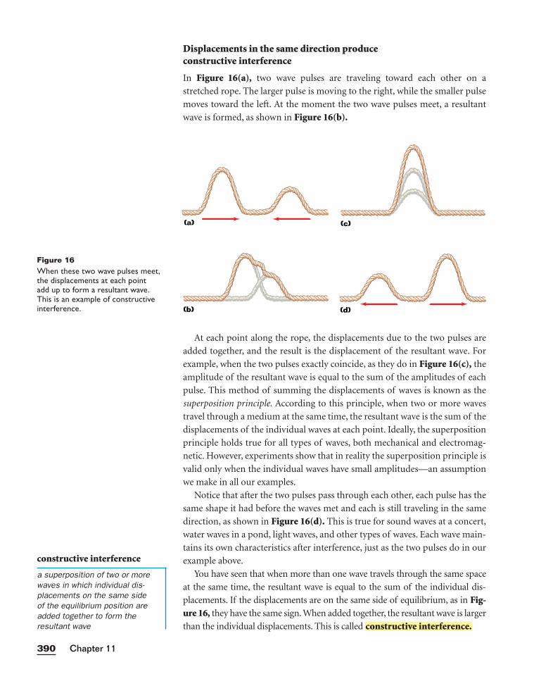
Displacements in the same direction produceconstructive interference
In Figure 16(a), two wave pulses are traveling toward each other on a
stretched rope. The larger pulse is moving to the right, while the smaller pulse
moves toward the left. At the moment the two wave pulses meet, a resultant
wave is formed, as shown in Figure 16(b).
At each point along the rope, the displacements due to the two pulses are
added together, and the result is the displacement of the resultant wave. For
example, when the two pulses exactly coincide, as they do in Figure 16(c), the
amplitude of the resultant wave is equal to the sum of the amplitudes of each
pulse. This method of summing the displacements of waves is known as the
superposition principle. According to this principle, when two or more waves
travel through a medium at the same time, the resultant wave is the sum of the
displacements of the individual waves at each point. Ideally, the superposition
principle holds true for all types of waves, both mechanical and electromag-
netic. However, experiments show that in reality the superposition principle is
valid only when the individual waves have small amplitudes—an assumption
we make in all our examples.
Notice that after the two pulses pass through each other, each pulse has the
same shape it had before the waves met and each is still traveling in the same
direction, as shown in Figure 16(d). This is true for sound waves at a concert,
water waves in a pond, light waves, and other types of waves. Each wave main-
tains its own characteristics after interference, just as the two pulses do in our
example above.
You have seen that when more than one wave travels through the same space
at the same time, the resultant wave is equal to the sum of the individual dis-
placements. If the displacements are on the same side of equilibrium, as in Fig-ure 16, they have the same sign. When added together, the resultant wave is larger
than the individual displacements. This is called constructive interference.
Chapter 11390
constructive interference
a superposition of two or morewaves in which individual dis-placements on the same side of the equilibrium position areadded together to form the resultant wave
(a)
(b)
(c)
(d)
Figure 16When these two wave pulses meet,the displacements at each pointadd up to form a resultant wave.This is an example of constructiveinterference.
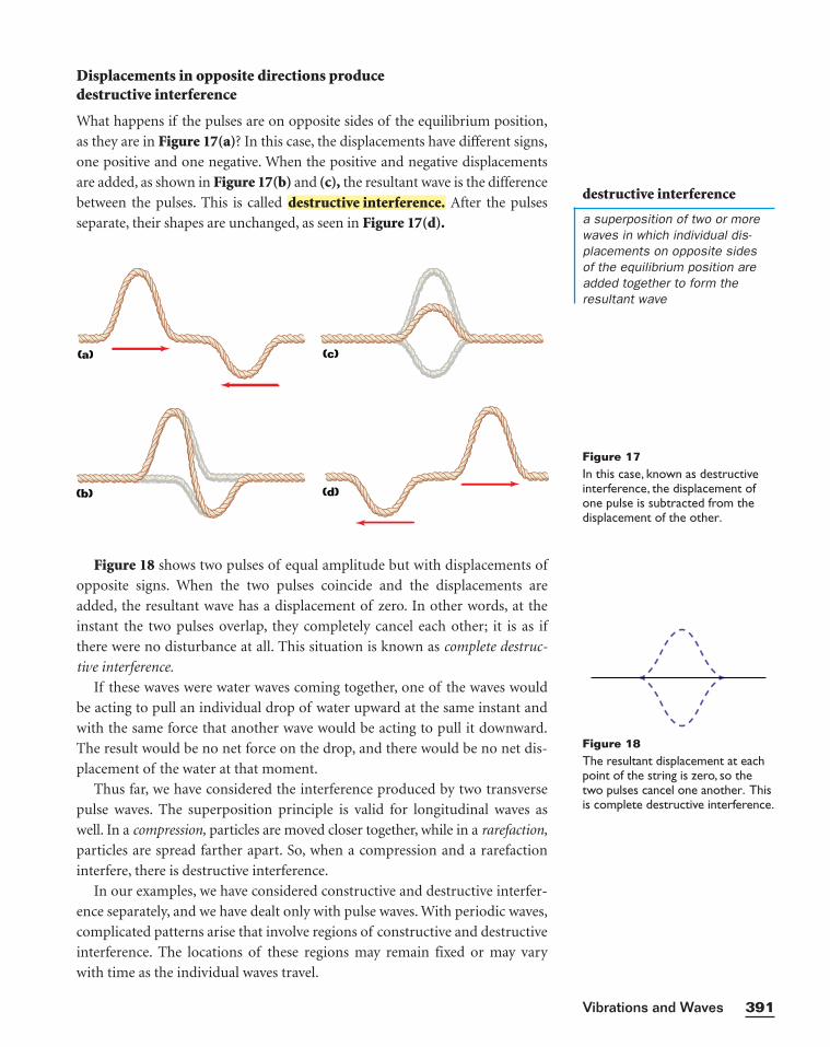
Displacements in opposite directions producedestructive interference
What happens if the pulses are on opposite sides of the equilibrium position,
as they are in Figure 17(a)? In this case, the displacements have different signs,
one positive and one negative. When the positive and negative displacements
are added, as shown in Figure 17(b) and (c), the resultant wave is the difference
between the pulses. This is called After the pulses
separate, their shapes are unchanged, as seen in Figure 17(d).destructive interference.
Figure 18 shows two pulses of equal amplitude but with displacements of
opposite signs. When the two pulses coincide and the displacements are
added, the resultant wave has a displacement of zero. In other words, at the
instant the two pulses overlap, they completely cancel each other; it is as if
there were no disturbance at all. This situation is known as complete destruc-
tive interference.
If these waves were water waves coming together, one of the waves would
be acting to pull an individual drop of water upward at the same instant and
with the same force that another wave would be acting to pull it downward.
The result would be no net force on the drop, and there would be no net dis-
placement of the water at that moment.
Thus far, we have considered the interference produced by two transverse
pulse waves. The superposition principle is valid for longitudinal waves as
well. In a compression, particles are moved closer together, while in a rarefaction,
particles are spread farther apart. So, when a compression and a rarefaction
interfere, there is destructive interference.
In our examples, we have considered constructive and destructive interfer-
ence separately, and we have dealt only with pulse waves. With periodic waves,
complicated patterns arise that involve regions of constructive and destructive
interference. The locations of these regions may remain fixed or may vary
with time as the individual waves travel.
391Vibrations and Waves
Figure 18The resultant displacement at eachpoint of the string is zero, so thetwo pulses cancel one another. Thisis complete destructive interference.
destructive interference
a superposition of two or morewaves in which individual dis-placements on opposite sides of the equilibrium position areadded together to form the resultant wave
(a)
(b)
(c)
(d)
Figure 17In this case, known as destructiveinterference, the displacement ofone pulse is subtracted from thedisplacement of the other.
REFLECTION
In our discussion of waves so far, we have assumed that the waves being ana-
lyzed could travel indefinitely without striking anything that would stop them
or otherwise change their motion. But what happens to the motion of a wave
when it reaches a boundary?
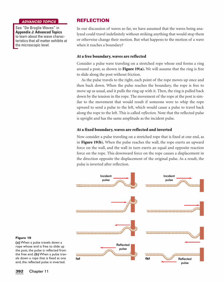
At a free boundary, waves are reflected
Consider a pulse wave traveling on a stretched rope whose end forms a ring
around a post, as shown in Figure 19(a). We will assume that the ring is free
to slide along the post without friction.
As the pulse travels to the right, each point of the rope moves up once and
then back down. When the pulse reaches the boundary, the rope is free to
move up as usual, and it pulls the ring up with it. Then, the ring is pulled back
down by the tension in the rope. The movement of the rope at the post is sim-
ilar to the movement that would result if someone were to whip the rope
upward to send a pulse to the left, which would cause a pulse to travel back
along the rope to the left. This is called reflection. Note that the reflected pulse
is upright and has the same amplitude as the incident pulse.
At a fixed boundary, waves are reflected and inverted
Now consider a pulse traveling on a stretched rope that is fixed at one end, as
in Figure 19(b). When the pulse reaches the wall, the rope exerts an upward
force on the wall, and the wall in turn exerts an equal and opposite reaction
force on the rope. This downward force on the rope causes a displacement in
the direction opposite the displacement of the original pulse. As a result, the
pulse is inverted after reflection.
Chapter 11392
(a)
Incidentpulse
Incidentpulse
Reflectedpulse
(b) Reflectedpulse
Figure 19(a) When a pulse travels down arope whose end is free to slide upthe post, the pulse is reflected fromthe free end. (b) When a pulse trav-els down a rope that is fixed at oneend, the reflected pulse is inverted.
ADVANCED TOPICS
See “De Broglie Waves” in Appendix J: Advanced Topicsto learn about the wave charac-teristics that all matter exhibits atthe microscopic level.
STANDING WAVES
Consider a string that is attached on one end to a rigid support and that is
shaken up and down in a regular motion at the other end. The regular motion
produces waves of a certain frequency, wavelength, and amplitude traveling
down the string. When the waves reach the other end, they are reflected back
toward the oncoming waves. If the string is vibrated at exactly the right fre-
quency, a —a resultant wave pattern that appears to be station-
ary on the string—is produced. The standing wave consists of alternating
regions of constructive and destructive interference.
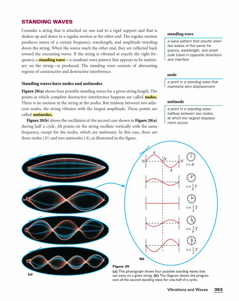
Standing waves have nodes and antinodes
Figure 20(a) shows four possible standing waves for a given string length. The
points at which complete destructive interference happens are called
There is no motion in the string at the nodes. But midway between two adja-
cent nodes, the string vibrates with the largest amplitude. These points are
called
Figure 20(b) shows the oscillation of the second case shown in Figure 20(a)during half a cycle. All points on the string oscillate vertically with the same
frequency, except for the nodes, which are stationary. In this case, there are
three nodes (N ) and two antinodes (A), as illustrated in the figure.
antinodes.
nodes.
standing wave
393Vibrations and Waves
t = T
t = 0N N
A
A
N
t = T
t = T
t = T
18
38
14
12
(a)
(b)
Figure 20(a) This photograph shows four possible standing waves that can exist on a given string. (b) The diagram shows the progres-sion of the second standing wave for one-half of a cycle.
node
a point in a standing wave thatmaintains zero displacement
standing wave
a wave pattern that results whentwo waves of the same fre-quency, wavelength, and ampli-tude travel in opposite directionsand interfere
antinode
a point in a standing wave,halfway between two nodes, at which the largest displace-ment occurs
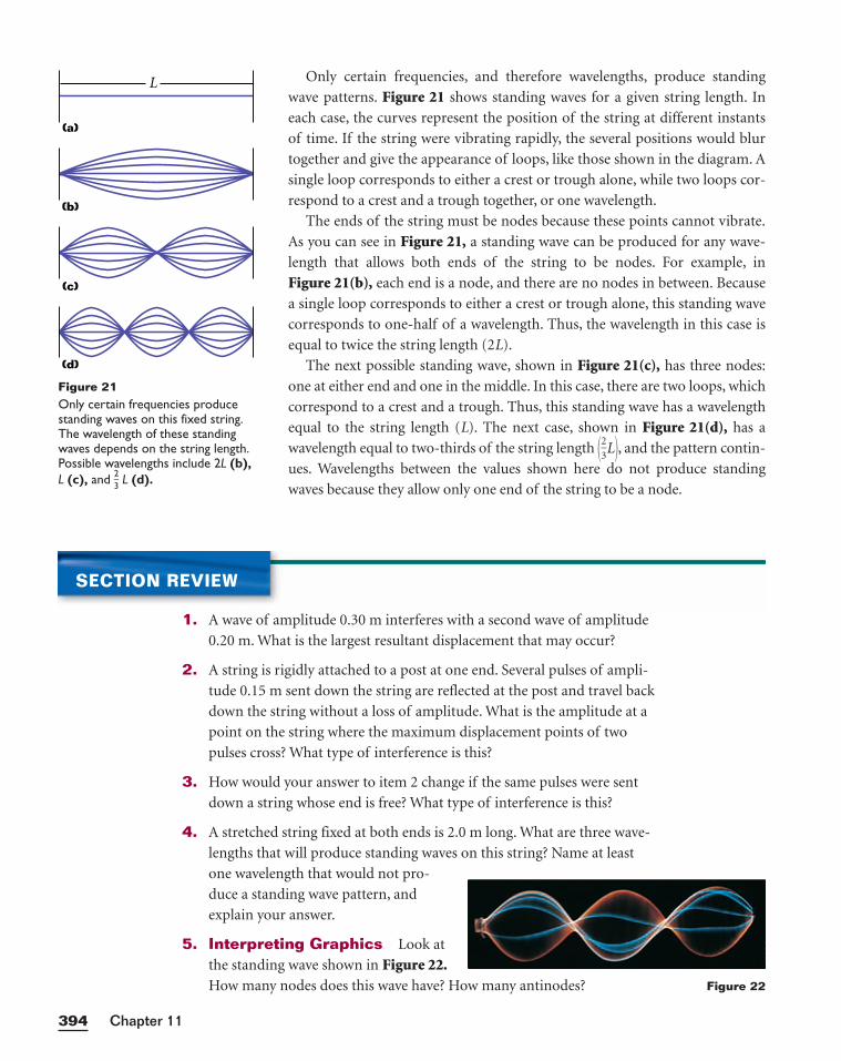
Only certain frequencies, and therefore wavelengths, produce standing
wave patterns. Figure 21 shows standing waves for a given string length. In
each case, the curves represent the position of the string at different instants
of time. If the string were vibrating rapidly, the several positions would blur
together and give the appearance of loops, like those shown in the diagram. A
single loop corresponds to either a crest or trough alone, while two loops cor-
respond to a crest and a trough together, or one wavelength.
The ends of the string must be nodes because these points cannot vibrate.
As you can see in Figure 21, a standing wave can be produced for any wave-
length that allows both ends of the string to be nodes. For example, in
Figure 21(b), each end is a node, and there are no nodes in between. Because
a single loop corresponds to either a crest or trough alone, this standing wave
corresponds to one-half of a wavelength. Thus, the wavelength in this case is
equal to twice the string length (2L).
The next possible standing wave, shown in Figure 21(c), has three nodes:
one at either end and one in the middle. In this case, there are two loops, which
correspond to a crest and a trough. Thus, this standing wave has a wavelength
equal to the string length (L). The next case, shown in Figure 21(d), has a
wavelength equal to two-thirds of the string length �23
L�, and the pattern contin-
ues. Wavelengths between the values shown here do not produce standing
waves because they allow only one end of the string to be a node.
Chapter 11394
SECTION REVIEW
1. A wave of amplitude 0.30 m interferes with a second wave of amplitude
0.20 m. What is the largest resultant displacement that may occur?
2. A string is rigidly attached to a post at one end. Several pulses of ampli-
tude 0.15 m sent down the string are reflected at the post and travel back
down the string without a loss of amplitude. What is the amplitude at a
point on the string where the maximum displacement points of two
pulses cross? What type of interference is this?
3. How would your answer to item 2 change if the same pulses were sent
down a string whose end is free? What type of interference is this?
4. A stretched string fixed at both ends is 2.0 m long. What are three wave-
lengths that will produce standing waves on this string? Name at least
one wavelength that would not pro-
duce a standing wave pattern, and
explain your answer.
5. Interpreting Graphics Look at
the standing wave shown in Figure 22.How many nodes does this wave have? How many antinodes?
Figure 21Only certain frequencies producestanding waves on this fixed string.The wavelength of these standingwaves depends on the string length.Possible wavelengths include 2L (b),L (c), and 2
3 L (d).
(a)
L
(b)
(c)
(d)
Figure 22
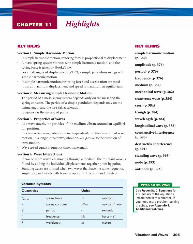
KEY IDEAS
Section 1 Simple Harmonic Motion• In simple harmonic motion, restoring force is proportional to displacement.
• A mass-spring system vibrates with simple harmonic motion, and the
spring force is given by Hooke’s law.
• For small angles of displacement (<15°), a simple pendulum swings with
simple harmonic motion.
• In simple harmonic motion, restoring force and acceleration are maxi-
mum at maximum displacement and speed is maximum at equilibrium.
Section 2 Measuring Simple Harmonic Motion• The period of a mass-spring system depends only on the mass and the
spring constant. The period of a simple pendulum depends only on the
string length and the free-fall acceleration.
• Frequency is the inverse of period.
Section 3 Properties of Waves• As a wave travels, the particles of the medium vibrate around an equilibri-
um position.
• In a transverse wave, vibrations are perpendicular to the direction of wave
motion. In a longitudinal wave, vibrations are parallel to the direction of
wave motion.
• Wave speed equals frequency times wavelength.
Section 4 Wave Interactions• If two or more waves are moving through a medium, the resultant wave is
found by adding the individual displacements together point by point.
• Standing waves are formed when two waves that have the same frequency,
amplitude, and wavelength travel in opposite directions and interfere.
KEY TERMS
simple harmonic motion (p. 369)
amplitude (p. 376)
period (p. 376)
frequency (p. 376)
medium (p. 382)
mechanical wave (p. 382)
transverse wave (p. 384)
crest (p. 384)
trough (p. 384)
wavelength (p. 384)
longitudinal wave (p. 385)
constructive interference (p. 390)
destructive interference (p. 391)
standing wave (p. 393)
node (p. 393)
antinode (p. 393)
HighlightsCHAPTER 11
395Vibrations and Waves
PROBLEM SOLVING
See Appendix D: Equations for a summary of the equationsintroduced in this chapter. Ifyou need more problem-solvingpractice, see Appendix I: Additional Problems.
Variable Symbols
Quantities Units
Felastic spring force N newtons
k spring constant N/m newtons/meter
T period s seconds
f frequency Hz hertz = s–1
l wavelength m meters
ReviewCHAPTER 11
SIMPLE HARMONIC MOTION
Review Questions
1. What characterizes an object’s motion as simpleharmonic?
2. List four examples of simple harmonic motion.
3. Does the acceleration of a simple harmonic oscilla-tor remain constant during its motion? Is the accel-eration ever zero? Explain.
4. A pendulum is released 40° from its resting posi-tion. Is its motion simple harmonic?
5. April is about to release the bob of a pendulum.Before she lets go, what sort of potential energy doesthe bob have? How does the energy of the bobchange as it swings through one full cycle of motion?
Conceptual Questions
6. An ideal mass-spring system vibrating with simple har-monic motion would oscillate indefinitely. Explain why.
7. In a simple pendulum, the weight of the bob can bedivided into two components, one tangent to thebob’s direction of motion and the other perpen-dicular to the bob’s direction of motion. Which ofthese is the restoring force, and why?
Practice Problems
For problems 8–9, see Sample Problem A.
8. Janet wants to find the spring constant of a givenspring, so she hangs the spring vertically and attachesa 0.40 kg mass to the spring’s other end. If the springstretches 3.0 cm from its equilibrium position, whatis the spring constant?
9. In preparing to shoot an arrow, an archer pulls abowstring back 0.40 m by exerting a force thatincreases uniformly from 0 to 230 N. What is theequivalent spring constant of the bow?
PERIOD AND FREQUENCY
Review Questions
10. A child swings on a playground swing. How manytimes does the child swing through the swing’sequilibrium position during the course of a singleperiod of motion?
11. What is the total distance traveled by an objectmoving back and forth in simple harmonic motionin a time interval equal to its period when its ampli-tude is equal to A?
12. How is the period of a simple harmonic vibrationrelated to its frequency?
Conceptual Questions
13. What happens to the period of a simple pendulumwhen the pendulum’s length is doubled? What hap-pens when the suspended mass is doubled?
14. A pendulum bob is made with a ball filled withwater. What would happen to the frequency ofvibration of this pendulum if a hole in the ballallowed water to slowly leak out? (Treat the pendu-lum as a simple pendulum.)
15. If a pendulum clock keeps perfect time at the baseof a mountain, will it also keep perfect time whenmoved to the top of the mountain? Explain.
16. If a grandfather clock is running slow, how can youadjust the length of the pendulum to correct thetime?
17. A simple pendulum can be used as an altimeter on aplane. How will the period of the pendulum vary asthe plane rises from the ground to its final cruisingaltitude?
18. Will the period of a vibrating mass-spring system onEarth be different from the period of an identicalmass-spring system on the moon? Why or why not?
Chapter 11396
Practice Problems
For problems 19–20, see Sample Problem B.
19. Find the length of a pendulum that oscillates with afrequency of 0.16 Hz.
20. A pendulum that moves through its equilibrium posi-tion once every 1.000 s is sometimes called a secondspendulum.
a. What is the period of any seconds pendulum?b. In Cambridge, England, a seconds pendulum is
0.9942 m long. What is the free-fall accelera-tion in Cambridge?
c. In Tokyo, Japan, a seconds pendulum is0.9927 m long. What is the free-fall accelera-tion in Tokyo?
For problem 21, see Sample Problem C.
21. A spring with a spring constant of 1.8 × 10² N/m isattached to a 1.5 kg mass and then set in motion.
a. What is the period of the mass-spring system?b. What is the frequency of the vibration?
PROPERTIES OF WAVES
Review Questions
22. What is common to all waves?
23. How do transverse and longitudinal waves differ?
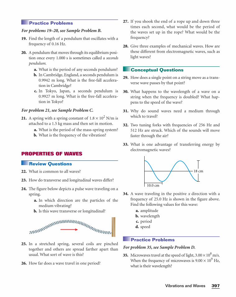
24. The figure below depicts a pulse wave traveling on aspring.
a. In which direction are the particles of themedium vibrating?
b. Is this wave transverse or longitudinal?
25. In a stretched spring, several coils are pinchedtogether and others are spread farther apart thanusual. What sort of wave is this?
26. How far does a wave travel in one period?
27. If you shook the end of a rope up and down threetimes each second, what would be the period ofthe waves set up in the rope? What would be thefrequency?
28. Give three examples of mechanical waves. How arethese different from electromagnetic waves, such aslight waves?
Conceptual Questions
29. How does a single point on a string move as a trans-verse wave passes by that point?
30. What happens to the wavelength of a wave on astring when the frequency is doubled? What hap-pens to the speed of the wave?
31. Why do sound waves need a medium throughwhich to travel?
32. Two tuning forks with frequencies of 256 Hz and512 Hz are struck. Which of the sounds will movefaster through the air?
33. What is one advantage of transferring energy byelectromagnetic waves?
34. A wave traveling in the positive x direction with afrequency of 25.0 Hz is shown in the figure above.Find the following values for this wave:
a. amplitudeb. wavelengthc. periodd. speed
Practice Problems
For problem 35, see Sample Problem D.
35. Microwaves travel at the speed of light, 3.00 × 10⁸ m/s.When the frequency of microwaves is 9.00 × 10⁹ Hz,what is their wavelength?
18 cm
10.0 cm
397Vibrations and Waves
WAVE INTERACTIONS
Review Questions
36. Using the superposition principle, draw the resultantwaves for each of the examples below.
37. What is the difference between constructive inter-ference and destructive interference?
38. Which one of the waveforms shown below is theresultant waveform?
39. Anthony sends a series of pulses of amplitude24 cm down a string that is attached to a post at oneend. Assuming the pulses are reflected with no lossof amplitude, what is the amplitude at a point onthe string where two pulses are crossing if
a. the string is rigidly attached to the post?b. the end at which reflection occurs is free to
slide up and down?
Conceptual Questions
40. Can more than two waves interfere in a givenmedium?
41. What is the resultant displacement at a positionwhere destructive interference is complete?
42. When two waves interfere, can the resultant wave belarger than either of the two original waves? If so,under what conditions?
43. Which of the following wavelengths will producestanding waves on a string that is 3.5 m long?
a. 1.75 mb. 3.5 mc. 5.0 md. 7.0 m
−y
0
+y
y2y1
y1 y1y3
y3
y3 y2y2
(a) (b)
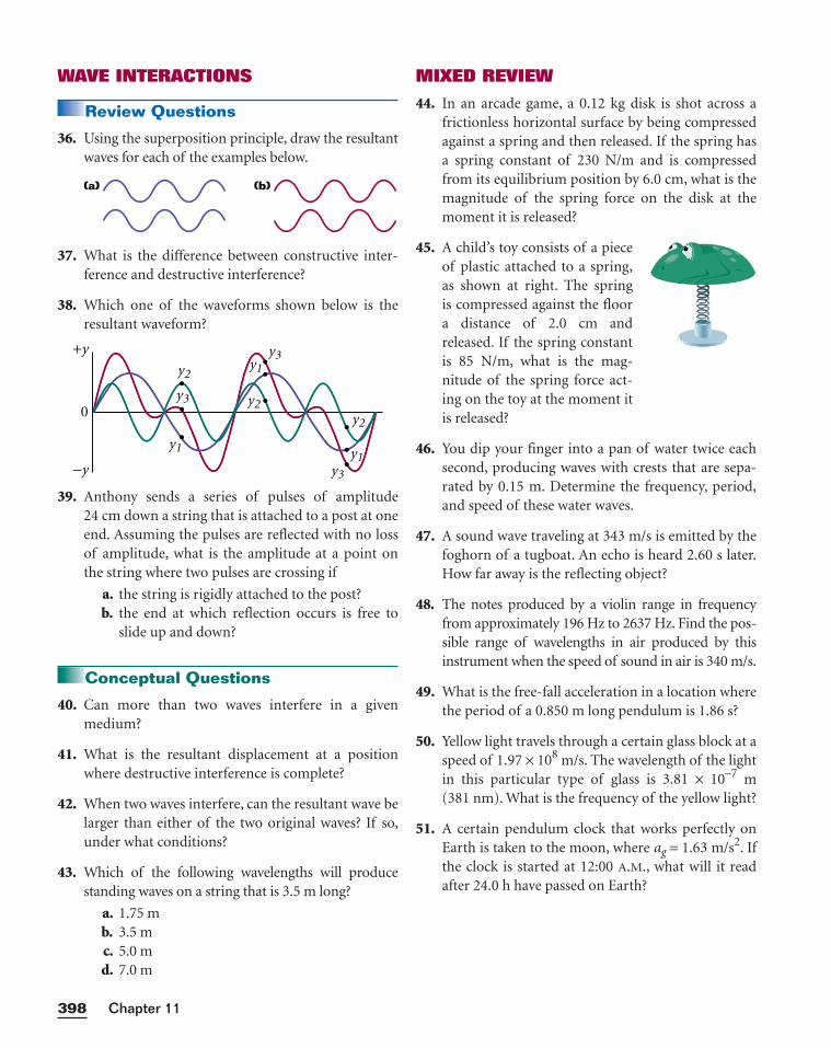
MIXED REVIEW
44. In an arcade game, a 0.12 kg disk is shot across africtionless horizontal surface by being compressedagainst a spring and then released. If the spring hasa spring constant of 230 N/m and is compressedfrom its equilibrium position by 6.0 cm, what is themagnitude of the spring force on the disk at themoment it is released?
45. A child’s toy consists of a pieceof plastic attached to a spring,as shown at right. The spring is compressed against the floor a distance of 2.0 cm andreleased. If the spring constantis 85 N/m, what is the mag-nitude of the spring force act-ing on the toy at the moment itis released?
46. You dip your finger into a pan of water twice eachsecond, producing waves with crests that are sepa-rated by 0.15 m. Determine the frequency, period,and speed of these water waves.
47. A sound wave traveling at 343 m/s is emitted by thefoghorn of a tugboat. An echo is heard 2.60 s later.How far away is the reflecting object?
48. The notes produced by a violin range in frequencyfrom approximately 196 Hz to 2637 Hz. Find the pos-sible range of wavelengths in air produced by thisinstrument when the speed of sound in air is 340 m/s.
49. What is the free-fall acceleration in a location wherethe period of a 0.850 m long pendulum is 1.86 s?
50. Yellow light travels through a certain glass block at aspeed of 1.97 × 10⁸ m/s. The wavelength of the lightin this particular type of glass is 3.81 × 10⁻⁷ m(381 nm). What is the frequency of the yellow light?
51. A certain pendulum clock that works perfectly onEarth is taken to the moon, where ag = 1.63 m/s2. Ifthe clock is started at 12:00 A.M., what will it readafter 24.0 h have passed on Earth?
Chapter 11398
399Vibrations and Waves
In this graphing calculator activity, you will enter
the period of a pendulum on Earth’s surface. The
calculator will use the previous equation to deter-
mine L, the length of the pendulum. The calculator
will then use this length to display a graph showing
how the period of this pendulum changes as free-
fall acceleration changes. You will use this graph to
find the period of a pendulum on various planets.
Visit go.hrw.com and type in the keyword
HF6VIBX to find this graphing calculator activity.
Refer to Appendix B for instructions on download-
ing the program for this activity.
PendulumWould a pendulum have the same period of oscilla-
tion on Mars, Venus, or Neptune? A pendulum’s
period, as you learned earlier in this chapter, is
described by the following equation:
T = 2p��⎯aLg⎯
In this equation, T is the period, L is the length of
the pendulum, and ag is the free-fall acceleration
(9.81 m/s2 on Earth’s surface). This equation can be
rearranged to solve for L if T is known.
L = ⎯a
4
g
pT
2
2
⎯
1. Design an experiment to compare the spring con-
stant and period of oscillation of a system built with
two (or more) springs connected in two ways: in
series (attached end to end) and in parallel (one end
of each spring anchored to a common point). If
your teacher approves your plan, obtain the neces-
sary equipment and perform the experiment.
2. The rule that the period of a pendulum is deter-
mined by its length is a good approximation for
amplitudes below 15°. Design an experiment to
investigate how amplitudes of oscillation greater
than 15° affect the motion of a pendulum.
List what equipment you would need, what
measurements you would perform, what data you
would record, and what you would calculate. If
your teacher approves your plan, obtain the neces-
sary equipment and perform the experiment.
3. Research earthquakes and different kinds of seismic
waves. Create a presentation about earthquakes that
includes answers to the following questions as well
as additional information: Do earthquakes travel
through oceans? What is transferred from place to
place as seismic waves propagate? What determines
their speed?
4. Identify examples of periodic motion in nature. Cre-
ate a chart describing the objects involved, their path
of motion, their periods, and the forces involved.
Which of the periodic motions are harmonic and
which are not?
Alternative Assessment
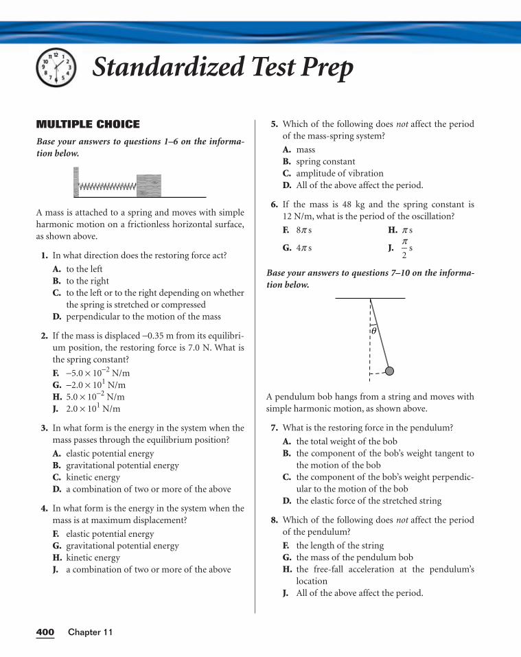
MULTIPLE CHOICE
Base your answers to questions 1–6 on the informa-tion below.
A mass is attached to a spring and moves with simpleharmonic motion on a frictionless horizontal surface,as shown above.
1. In what direction does the restoring force act?
A. to the leftB. to the rightC. to the left or to the right depending on whether
the spring is stretched or compressedD. perpendicular to the motion of the mass
2. If the mass is displaced −0.35 m from its equilibri-um position, the restoring force is 7.0 N. What isthe spring constant?
F. −5.0 × 10⁻² N/mG. −2.0 × 101 N/mH. 5.0 × 10⁻² N/mJ. 2.0 × 101 N/m
3. In what form is the energy in the system when themass passes through the equilibrium position?
A. elastic potential energyB. gravitational potential energyC. kinetic energyD. a combination of two or more of the above
4. In what form is the energy in the system when themass is at maximum displacement?
F. elastic potential energyG. gravitational potential energyH. kinetic energyJ. a combination of two or more of the above
5. Which of the following does not affect the periodof the mass-spring system?
A. massB. spring constantC. amplitude of vibrationD. All of the above affect the period.
6. If the mass is 48 kg and the spring constant is12 N/m, what is the period of the oscillation?
Base your answers to questions 7–10 on the informa-tion below.
A pendulum bob hangs from a string and moves withsimple harmonic motion, as shown above.
7. What is the restoring force in the pendulum?
A. the total weight of the bobB. the component of the bob’s weight tangent to
the motion of the bobC. the component of the bob’s weight perpendic-
ular to the motion of the bobD. the elastic force of the stretched string
8. Which of the following does not affect the periodof the pendulum?
F. the length of the stringG. the mass of the pendulum bobH. the free-fall acceleration at the pendulum’s
locationJ. All of the above affect the period.
θ
F. 8p s
G. 4p s
H. p s
J. p2
s
Chapter 11400
Standardized Test Prep
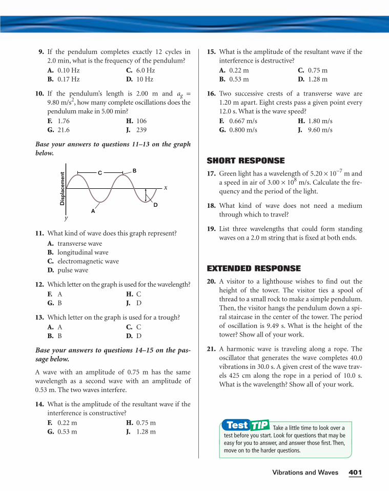
9. If the pendulum completes exactly 12 cycles in2.0 min, what is the frequency of the pendulum?
10. If the pendulum’s length is 2.00 m and ag =9.80 m/s2, how many complete oscillations does thependulum make in 5.00 min?
Base your answers to questions 11–13 on the graphbelow.
11. What kind of wave does this graph represent?
A. transverse waveB. longitudinal waveC. electromagnetic waveD. pulse wave
12. Which letter on the graph is used for the wavelength?
13. Which letter on the graph is used for a trough?
Base your answers to questions 14–15 on the pas-sage below.
A wave with an amplitude of 0.75 m has the samewavelength as a second wave with an amplitude of0.53 m. The two waves interfere.
14. What is the amplitude of the resultant wave if theinterference is constructive?
F. 0.22 mG. 0.53 m
H. 0.75 mJ. 1.28 m
A. AB. B
C. CD. D
F. AG. B
H. CJ. D
Dis
plac
emen
t
x
y
BC
AD
F. 1.76G. 21.6
H. 106J. 239
A. 0.10 HzB. 0.17 Hz
C. 6.0 HzD. 10 Hz
15. What is the amplitude of the resultant wave if theinterference is destructive?
16. Two successive crests of a transverse wave are1.20 m apart. Eight crests pass a given point every12.0 s. What is the wave speed?
SHORT RESPONSE
17. Green light has a wavelength of 5.20 × 10⁻⁷ m anda speed in air of 3.00 × 10⁸ m/s. Calculate the fre-quency and the period of the light.
18. What kind of wave does not need a mediumthrough which to travel?
19. List three wavelengths that could form standingwaves on a 2.0 m string that is fixed at both ends.
EXTENDED RESPONSE
20. A visitor to a lighthouse wishes to find out theheight of the tower. The visitor ties a spool ofthread to a small rock to make a simple pendulum.Then, the visitor hangs the pendulum down a spi-ral staircase in the center of the tower. The periodof oscillation is 9.49 s. What is the height of thetower? Show all of your work.
21. A harmonic wave is traveling along a rope. Theoscillator that generates the wave completes 40.0vibrations in 30.0 s. A given crest of the wave trav-els 425 cm along the rope in a period of 10.0 s.What is the wavelength? Show all of your work.
F. 0.667 m/sG. 0.800 m/s
H. 1.80 m/sJ. 9.60 m/s
A. 0.22 mB. 0.53 m
C. 0.75 mD. 1.28 m
401Vibrations and Waves
Take a little time to look over atest before you start. Look for questions that may beeasy for you to answer, and answer those first. Then,move on to the harder questions.
Chapter 11402
The period of a pendulum is the time required for the pendulum to complete
one cycle. In this lab, you will construct models of a simple pendulum using
different masses and lengths of cord. You will design an experiment to meas-
ure the period of each model and to determine how the period depends on
length and mass. Your experiment should include several trials at a constant
mass but at different lengths, and several more trials at constant length but
with different masses. In the Analysis, you will also use the period and the
length of the cord for each trial to calculate the free-fall acceleraction, ag, at
your geographical location.
PROCEDURE
1. Study the materials provided, and design an experiment to meet the
goals stated above.
2. Write out your lab procedure, including a detailed description of the
measurements to take during each step and the number of trials to per-
form. You may use Figure 1 as a guide to a possible setup. You should
keep the amplitude of the swing less than 15° in each trial.
3. Ask your teacher to approve your procedure.
4. Follow all steps of your procedure.
5. Clean up your work area. Put equipment away safely so that it is ready to
be used again.
OBJECTIVES
•Construct simple pendu-lums, and find theirperiods.
•Calculate the value for ag,the free-fall acceleration.
•Examine the relation-ships between length,mass, and period for dif-ferent pendulums.
MATERIALS LIST• balance• cord• meterstick• pendulum bobs• pendulum clamp• protractor• stopwatch• support stand
Inquiry LabCHAPTER 11
Design Your Own
Simple Harmonic Motion of a Pendulum
SAFETY
• Tie back long hair, secure loose clothing, and remove loose jewelry toprevent their getting caught in moving parts or pulleys. Put on goggles.
• Attach masses to the thread and the thread to clamps securely. Swingmasses in areas free of people and obstacles. Swinging or droppedmasses can cause serious injury.
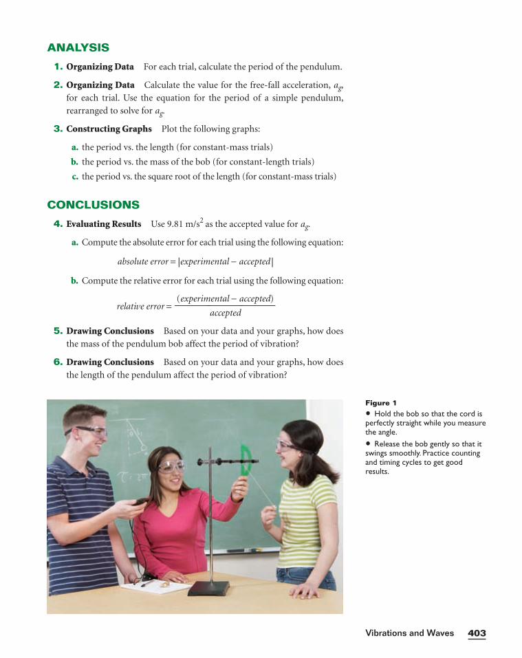
403
ANALYSIS
1. Organizing Data For each trial, calculate the period of the pendulum.
2. Organizing Data Calculate the value for the free-fall acceleration, ag,
for each trial. Use the equation for the period of a simple pendulum,
rearranged to solve for ag.
3. Constructing Graphs Plot the following graphs:
a. the period vs. the length (for constant-mass trials)
b. the period vs. the mass of the bob (for constant-length trials)
c. the period vs. the square root of the length (for constant-mass trials)
CONCLUSIONS
4. Evaluating Results Use 9.81 m/s2 as the accepted value for ag.
a. Compute the absolute error for each trial using the following equation:
absolute error = |experimental − accepted |
b. Compute the relative error for each trial using the following equation:
relative error =
5. Drawing Conclusions Based on your data and your graphs, how does
the mass of the pendulum bob affect the period of vibration?
6. Drawing Conclusions Based on your data and your graphs, how does
the length of the pendulum affect the period of vibration?
(experimental − accepted)
accepted
Vibrations and Waves
Figure 1
• Hold the bob so that the cord isperfectly straight while you measurethe angle.
• Release the bob gently so that itswings smoothly. Practice countingand timing cycles to get goodresults.
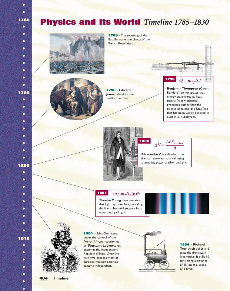
1789 – The storming of theBastille marks the climax of theFrench Revolution.
1804 – RichardTrevithick builds andtests the first steamlocomotive. It pulls 10tons along a distanceof 15 km at a speedof 8 km/h.
1804 – Saint-Domingue,under the control of theFrench-African majority ledby Toussaint-Louverture,becomes the independentRepublic of Haiti. Over thenext two decades most ofEurope’s western coloniesbecome independent.
1796 – EdwardJenner develops thesmallpox vaccine.
Physics and Its World Timeline 1785–1830
1798 Q = mcp∆T
Benjamin Thompson (CountRumford) demonstrates thatenergy transferred as heatresults from mechanicalprocesses, rather than therelease of caloric, the heat fluidthat has been widely believed toexist in all substances.
Timeline404
Alessandro Volta develops thefirst current-electricity cell usingalternating plates of silver and zinc.
1800∆V =
∆PE electric
q
ml = d(sinq)Thomas Young demonstratesthat light rays interfere, providingthe first substantial support for awave theory of light.
1801
••
1780
•••••••••
1790
•••••••••
1800
•••••••••
1810
•••••••
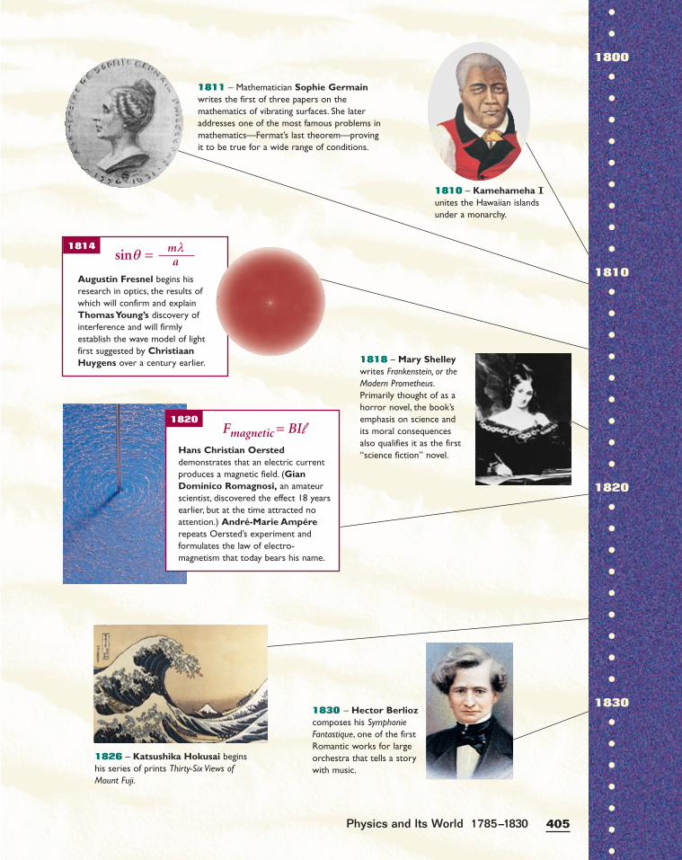
1810 – Kamehameha Iunites the Hawaiian islandsunder a monarchy.
1811 – Mathematician Sophie Germainwrites the first of three papers on themathematics of vibrating surfaces. She lateraddresses one of the most famous problems inmathematics—Fermat’s last theorem—provingit to be true for a wide range of conditions.
1826 – Katsushika Hokusai beginshis series of prints Thirty-Six Views ofMount Fuji.
1818 – Mary Shelleywrites Frankenstein, or theModern Prometheus.Primarily thought of as ahorror novel, the book’semphasis on science andits moral consequencesalso qualifies it as the first“science fiction” novel.
1830 – Hector Berliozcomposes his SymphonieFantastique, one of the firstRomantic works for largeorchestra that tells a storywith music.
Augustin Fresnel begins hisresearch in optics, the results ofwhich will confirm and explainThomas Young’s discovery ofinterference and will firmlyestablish the wave model of lightfirst suggested by ChristiaanHuygens over a century earlier.
1814sinq = ml
a
405Physics and Its World 1785–1830
Hans Christian Oersteddemonstrates that an electric currentproduces a magnetic field. (GianDominico Romagnosi, an amateurscientist, discovered the effect 18 yearsearlier, but at the time attracted noattention.) André-Marie Ampérerepeats Oersted’s experiment andformulates the law of electro-magnetism that today bears his name.
1820Fmagnetic = BIl
••
1800
•••••••••
1810
•••••••••
1820
•••••••••
1830
•••••••

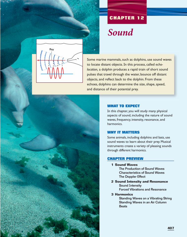
407
Some marine mammals, such as dolphins, use sound wavesto locate distant objects. In this process, called echo-location, a dolphin produces a rapid train of short soundpulses that travel through the water, bounce off distantobjects, and reflect back to the dolphin. From theseechoes, dolphins can determine the size, shape, speed,and distance of their potential prey.
CHAPTER 12
Ray
Sound
WHAT TO EXPECTIn this chapter, you will study many physicalaspects of sound, including the nature of soundwaves, frequency, intensity, resonance, and harmonics.
WHY IT MATTERSSome animals, including dolphins and bats, usesound waves to learn about their prey. Musicalinstruments create a variety of pleasing soundsthrough different harmonics.
CHAPTER PREVIEW
1 Sound WavesThe Production of Sound WavesCharacteristics of Sound WavesThe Doppler Effect
2 Sound Intensity and ResonanceSound IntensityForced Vibrations and Resonance
3 HarmonicsStanding Waves on a Vibrating StringStanding Waves in an Air ColumnBeats
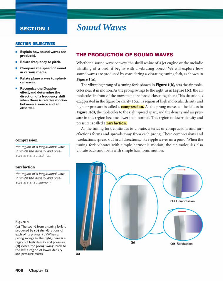
Sound WavesSECTION 1
THE PRODUCTION OF SOUND WAVES
Whether a sound wave conveys the shrill whine of a jet engine or the melodic
whistling of a bird, it begins with a vibrating object. We will explore how
sound waves are produced by considering a vibrating tuning fork, as shown in
Figure 1(a).The vibrating prong of a tuning fork, shown in Figure 1(b), sets the air mole-
cules near it in motion. As the prong swings to the right, as in Figure 1(c), the air
molecules in front of the movement are forced closer together. (This situation is
exaggerated in the figure for clarity.) Such a region of high molecular density and
high air pressure is called a As the prong moves to the left, as in
Figure 1(d), the molecules to the right spread apart, and the density and air pres-
sure in this region become lower than normal. This region of lower density and
pressure is called a
As the tuning fork continues to vibrate, a series of compressions and rar-
efactions forms and spreads away from each prong. These compressions and
rarefactions spread out in all directions, like ripple waves on a pond. When the
tuning fork vibrates with simple harmonic motion, the air molecules also
vibrate back and forth with simple harmonic motion.
rarefaction.
compression.
Chapter 12408
SECTION OBJECTIVES
■ Explain how sound waves areproduced.
■ Relate frequency to pitch.
■ Compare the speed of soundin various media.
■ Relate plane waves to spheri-cal waves.
■ Recognize the Dopplereffect, and determine thedirection of a frequency shiftwhen there is relative motionbetween a source and anobserver.
Figure 1(a) The sound from a tuning fork isproduced by (b) the vibrations ofeach of its prongs. (c) When aprong swings to the right, there is aregion of high density and pressure.(d) When the prong swings back tothe left, a region of lower densityand pressure exists.
Compression
Rarefaction
99 C 3 00 00 a,b
(b)
(c)
(d)
compression
the region of a longitudinal wavein which the density and pres-sure are at a maximum
rarefaction
the region of a longitudinal wavein which the density and pres-sure are at a minimum
(a)
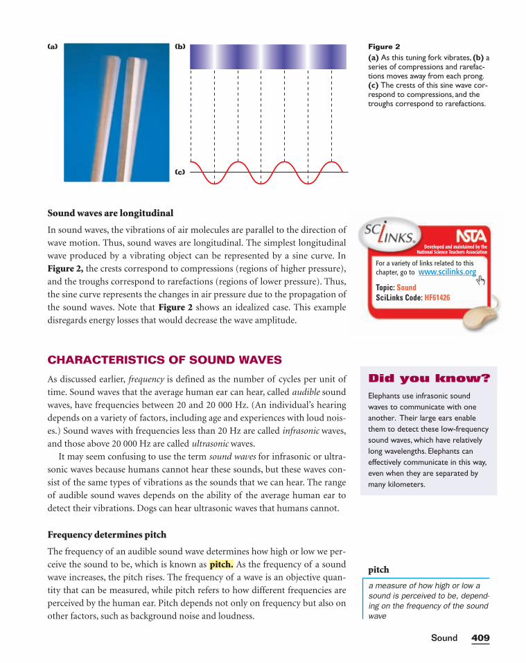
Sound waves are longitudinal
In sound waves, the vibrations of air molecules are parallel to the direction of
wave motion. Thus, sound waves are longitudinal. The simplest longitudinal
wave produced by a vibrating object can be represented by a sine curve. In
Figure 2, the crests correspond to compressions (regions of higher pressure),
and the troughs correspond to rarefactions (regions of lower pressure). Thus,
the sine curve represents the changes in air pressure due to the propagation of
the sound waves. Note that Figure 2 shows an idealized case. This example
disregards energy losses that would decrease the wave amplitude.
CHARACTERISTICS OF SOUND WAVES
As discussed earlier, frequency is defined as the number of cycles per unit of
time. Sound waves that the average human ear can hear, called audible sound
waves, have frequencies between 20 and 20 000 Hz. (An individual’s hearing
depends on a variety of factors, including age and experiences with loud nois-
es.) Sound waves with frequencies less than 20 Hz are called infrasonic waves,
and those above 20 000 Hz are called ultrasonic waves.
It may seem confusing to use the term sound waves for infrasonic or ultra-
sonic waves because humans cannot hear these sounds, but these waves con-
sist of the same types of vibrations as the sounds that we can hear. The range
of audible sound waves depends on the ability of the average human ear to
detect their vibrations. Dogs can hear ultrasonic waves that humans cannot.
Frequency determines pitch
The frequency of an audible sound wave determines how high or low we per-
ceive the sound to be, which is known as As the frequency of a sound
wave increases, the pitch rises. The frequency of a wave is an objective quan-
tity that can be measured, while pitch refers to how different frequencies are
perceived by the human ear. Pitch depends not only on frequency but also on
other factors, such as background noise and loudness.
pitch.
409Sound
pitch
a measure of how high or low asound is perceived to be, depend-ing on the frequency of the soundwave
Figure 2(a) As this tuning fork vibrates, (b) aseries of compressions and rarefac-tions moves away from each prong.(c) The crests of this sine wave cor-respond to compressions, and thetroughs correspond to rarefactions.
(a) (b)
(c)
Developed and maintained by theNational Science Teachers Association
For a variety of links related to thischapter, go to www.scilinks.org
Topic: SoundSciLinks Code: HF61426
Elephants use infrasonic soundwaves to communicate with oneanother. Their large ears enablethem to detect these low-frequencysound waves, which have relativelylong wavelengths. Elephants caneffectively communicate in this way,even when they are separated bymany kilometers.
Did you know?
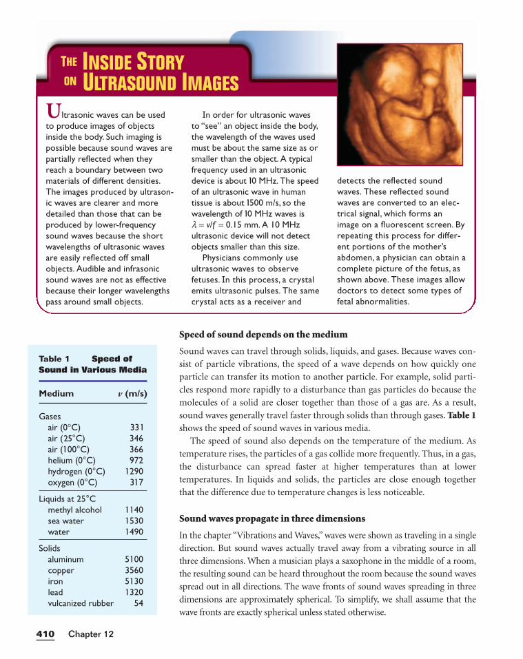
Speed of sound depends on the medium
Sound waves can travel through solids, liquids, and gases. Because waves con-
sist of particle vibrations, the speed of a wave depends on how quickly one
particle can transfer its motion to another particle. For example, solid parti-
cles respond more rapidly to a disturbance than gas particles do because the
molecules of a solid are closer together than those of a gas are. As a result,
sound waves generally travel faster through solids than through gases. Table 1shows the speed of sound waves in various media.
The speed of sound also depends on the temperature of the medium. As
temperature rises, the particles of a gas collide more frequently. Thus, in a gas,
the disturbance can spread faster at higher temperatures than at lower
temperatures. In liquids and solids, the particles are close enough together
that the difference due to temperature changes is less noticeable.
Sound waves propagate in three dimensions
In the chapter “Vibrations and Waves,” waves were shown as traveling in a single
direction. But sound waves actually travel away from a vibrating source in all
three dimensions. When a musician plays a saxophone in the middle of a room,
the resulting sound can be heard throughout the room because the sound waves
spread out in all directions. The wave fronts of sound waves spreading in three
dimensions are approximately spherical. To simplify, we shall assume that the
wave fronts are exactly spherical unless stated otherwise.
Chapter 12410
Ultrasonic waves can be usedto produce images of objectsinside the body. Such imaging ispossible because sound waves arepartially reflected when theyreach a boundary between twomaterials of different densities.The images produced by ultrason-ic waves are clearer and moredetailed than those that can beproduced by lower-frequencysound waves because the shortwavelengths of ultrasonic wavesare easily reflected off smallobjects. Audible and infrasonicsound waves are not as effectivebecause their longer wavelengthspass around small objects.
In order for ultrasonic wavesto “see” an object inside the body,the wavelength of the waves usedmust be about the same size as orsmaller than the object. A typicalfrequency used in an ultrasonicdevice is about 10 MHz. The speedof an ultrasonic wave in human tissue is about 1500 m/s, so thewavelength of 10 MHz waves is l = v/f = 0.15 mm. A 10 MHzultrasonic device will not detectobjects smaller than this size.
Physicians commonly useultrasonic waves to observefetuses. In this process, a crystalemits ultrasonic pulses. The samecrystal acts as a receiver and
detects the reflected soundwaves. These reflected soundwaves are converted to an elec-trical signal, which forms animage on a fluorescent screen. Byrepeating this process for differ-ent portions of the mother’sabdomen, a physician can obtain acomplete picture of the fetus, asshown above. These images allowdoctors to detect some types offetal abnormalities.
THE INSIDE STORYON ULTRASOUND IMAGES
Table 1 Speed ofSound in Various Media
Medium v (m/s)
Gasesair (0°C) 33 1air (25°C) 346air (100°C) 366helium (0°C) 972hydrogen (0°C) 1290oxygen (0°C) 317
Liquids at 25°Cmethyl alcohol 1 140sea water 1530water 1490
Solidsaluminum 5 100copper 3560iron 5 130lead 1320vulcanized rubber 54
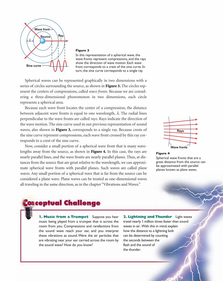
Source
Wave front
Ray
Sine curve
λ
Figure 3In this representation of a spherical wave, thewave fronts represent compressions, and the raysshow the direction of wave motion. Each wavefront corresponds to a crest of the sine curve. Inturn, the sine curve corresponds to a single ray.
Rays
Wave fronts
Figure 4Spherical wave fronts that are agreat distance from the source canbe approximated with parallelplanes known as plane waves.
2. Lightning and Thunder Light waves travel nearly 1 million times faster than sound waves in air. With this in mind, explain how the distance to a lightning bolt can be determined by counting the seconds between the flash and the sound of the thunder.
1. Music from a Trumpet Suppose you hearmusic being played from a trumpet that is across theroom from you. Compressions and rarefactions fromthe sound wave reach your ear, and you interpretthese vibrations as sound.Were the air particles thatare vibrating near your ear carried across the room bythe sound wave? How do you know?
Spherical waves can be represented graphically in two dimensions with a
series of circles surrounding the source, as shown in Figure 3. The circles rep-
resent the centers of compressions, called wave fronts. Because we are consid-
ering a three-dimensional phenomenon in two dimensions, each circle
represents a spherical area.
Because each wave front locates the center of a compression, the distance
between adjacent wave fronts is equal to one wavelength, l. The radial lines
perpendicular to the wave fronts are called rays. Rays indicate the direction of
the wave motion. The sine curve used in our previous representation of sound
waves, also shown in Figure 3, corresponds to a single ray. Because crests of
the sine curve represent compressions, each wave front crossed by this ray cor-
responds to a crest of the sine curve.
Now, consider a small portion of a spherical wave front that is many wave-
lengths away from the source, as shown in Figure 4. In this case, the rays are
nearly parallel lines, and the wave fronts are nearly parallel planes. Thus, at dis-
tances from the source that are great relative to the wavelength, we can approxi-
mate spherical wave fronts with parallel planes. Such waves are called plane
waves. Any small portion of a spherical wave that is far from the source can be
considered a plane wave. Plane waves can be treated as one-dimensional waves
all traveling in the same direction, as in the chapter “Vibrations and Waves.”
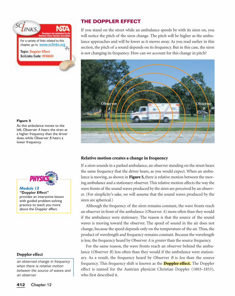
THE DOPPLER EFFECT
If you stand on the street while an ambulance speeds by with its siren on, you
will notice the pitch of the siren change. The pitch will be higher as the ambu-
lance approaches and will be lower as it moves away. As you read earlier in this
section, the pitch of a sound depends on its frequency. But in this case, the siren
is not changing its frequency. How can we account for this change in pitch?
Relative motion creates a change in frequency
If a siren sounds in a parked ambulance, an observer standing on the street hears
the same frequency that the driver hears, as you would expect. When an ambu-
lance is moving, as shown in Figure 5, there is relative motion between the mov-
ing ambulance and a stationary observer. This relative motion affects the way the
wave fronts of the sound waves produced by the siren are perceived by an observ-
er. (For simplicity’s sake, we will assume that the sound waves produced by the
siren are spherical.)
Although the frequency of the siren remains constant, the wave fronts reach
an observer in front of the ambulance (Observer A) more often than they would
if the ambulance were stationary. The reason is that the source of the sound
waves is moving toward the observer. The speed of sound in the air does not
change, because the speed depends only on the temperature of the air. Thus, the
product of wavelength and frequency remains constant. Because the wavelength
is less, the frequency heard by Observer A is greater than the source frequency.
For the same reason, the wave fronts reach an observer behind the ambu-
lance (Observer B) less often than they would if the ambulance were station-
ary. As a result, the frequency heard by Observer B is less than the source
frequency. This frequency shift is known as the The Doppler
effect is named for the Austrian physicist Christian Doppler (1803–1853),
who first described it.
Doppler effect.
Chapter 12412
Figure 5As this ambulance moves to theleft, Observer A hears the siren at a higher frequency than the driverdoes, while Observer B hears alower frequency.
Doppler effect
an observed change in frequencywhen there is relative motionbetween the source of waves andan observer
Developed and maintained by theNational Science Teachers Association
For a variety of links related to thischapter, go to www.scilinks.org
Topic: Doppler EffectSciLinks Code: HF60424
ObserverA
ObserverB
PHYSICSPHYSICSModule 13“Doppler Effect”provides an interactive lessonwith guided problem-solvingpractice to teach you moreabout the Doppler effect.
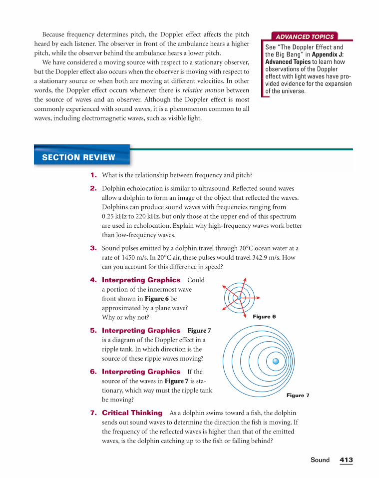
Because frequency determines pitch, the Doppler effect affects the pitch
heard by each listener. The observer in front of the ambulance hears a higher
pitch, while the observer behind the ambulance hears a lower pitch.
We have considered a moving source with respect to a stationary observer,
but the Doppler effect also occurs when the observer is moving with respect to
a stationary source or when both are moving at different velocities. In other
words, the Doppler effect occurs whenever there is relative motion between
the source of waves and an observer. Although the Doppler effect is most
commonly experienced with sound waves, it is a phenomenon common to all
waves, including electromagnetic waves, such as visible light.
413Sound
ADVANCED TOPICS
See “The Doppler Effect andthe Big Bang” in Appendix J:Advanced Topics to learn howobservations of the Dopplereffect with light waves have pro-vided evidence for the expansionof the universe.
SECTION REVIEW
1. What is the relationship between frequency and pitch?
2. Dolphin echolocation is similar to ultrasound. Reflected sound waves
allow a dolphin to form an image of the object that reflected the waves.
Dolphins can produce sound waves with frequencies ranging from
0.25 kHz to 220 kHz, but only those at the upper end of this spectrum
are used in echolocation. Explain why high-frequency waves work better
than low-frequency waves.
3. Sound pulses emitted by a dolphin travel through 20°C ocean water at a
rate of 1450 m/s. In 20°C air, these pulses would travel 342.9 m/s. How
can you account for this difference in speed?
4. Interpreting Graphics Could
a portion of the innermost wave
front shown in Figure 6 be
approximated by a plane wave?
Why or why not?
5. Interpreting Graphics Figure 7is a diagram of the Doppler effect in a
ripple tank. In which direction is the
source of these ripple waves moving?
6. Interpreting Graphics If the
source of the waves in Figure 7 is sta-
tionary, which way must the ripple tank
be moving?
7. Critical Thinking As a dolphin swims toward a fish, the dolphin
sends out sound waves to determine the direction the fish is moving. If
the frequency of the reflected waves is higher than that of the emitted
waves, is the dolphin catching up to the fish or falling behind?
Figure 6
Figure 7
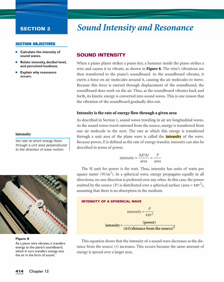
Sound Intensity and ResonanceSECTION 2
SOUND INTENSITY
When a piano player strikes a piano key, a hammer inside the piano strikes a
wire and causes it to vibrate, as shown in Figure 8. The wire’s vibrations are
then transferred to the piano’s soundboard. As the soundboard vibrates, it
exerts a force on air molecules around it, causing the air molecules to move.
Because this force is exerted through displacement of the soundboard, the
soundboard does work on the air. Thus, as the soundboard vibrates back and
forth, its kinetic energy is converted into sound waves. This is one reason that
the vibration of the soundboard gradually dies out.
Intensity is the rate of energy flow through a given area
As described in Section 1, sound waves traveling in air are longitudinal waves.
As the sound waves travel outward from the source, energy is transferred from
one air molecule to the next. The rate at which this energy is transferred
through a unit area of the plane wave is called the of the wave.
Because power, P, is defined as the rate of energy transfer, intensity can also be
described in terms of power.
intensity = ∆a
E
r
/
e
∆a
t =
ar
P
ea
The SI unit for power is the watt. Thus, intensity has units of watts per
square meter (W/m2). In a spherical wave, energy propagates equally in all
directions; no one direction is preferred over any other. In this case, the power
emitted by the source (P) is distributed over a spherical surface (area = 4pr2),
assuming that there is no absorption in the medium.
This equation shows that the intensity of a sound wave decreases as the dis-
tance from the source (r) increases. This occurs because the same amount of
energy is spread over a larger area.
INTENSITY OF A SPHERICAL WAVE
intensity = 4p
P
r2
(power)intensity =
(4p)(distance from the source)2
intensity
Chapter 12414
SECTION OBJECTIVES
■ Calculate the intensity ofsound waves.
■ Relate intensity, decibel level,and perceived loudness.
■ Explain why resonanceoccurs.
Figure 8As a piano wire vibrates, it transfersenergy to the piano’s soundboard,which in turn transfers energy intothe air in the form of sound.
intensity
the rate at which energy flowsthrough a unit area perpendicularto the direction of wave motion
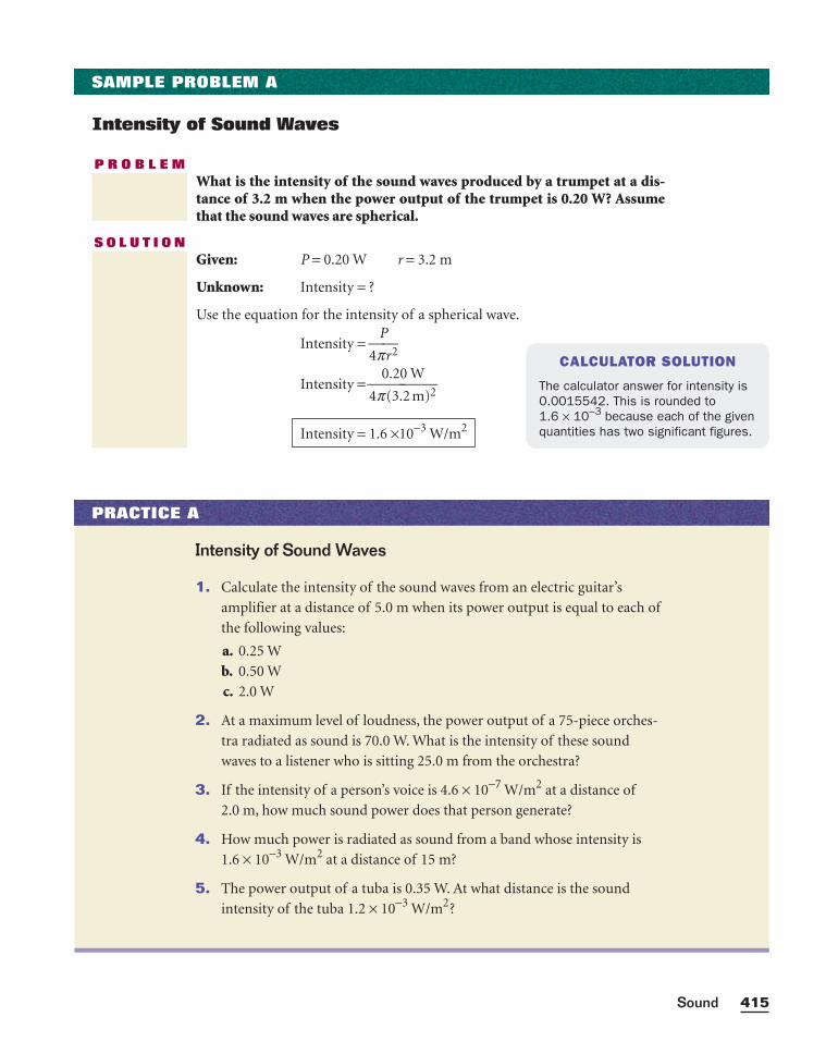
415Sound
SAMPLE PROBLEM A
Intensity of Sound Waves
P R O B L E MWhat is the intensity of the sound waves produced by a trumpet at a dis-tance of 3.2 m when the power output of the trumpet is 0.20 W? Assumethat the sound waves are spherical.
S O L U T I O NGiven: P = 0.20 W r = 3.2 m
Unknown: Intensity = ?
Use the equation for the intensity of a spherical wave.
Intensity = 4p
P
r2
Intensity = 4p
0
(
.
3
2
.
0
2
W
m)2
Intensity = 1.6 ×10⁻³ W/m2
CALCULATOR SOLUTION
The calculator answer for intensity is0.0015542. This is rounded to 1.6 × 10⁻³ because each of the givenquantities has two significant figures.
PRACTICE A
Intensity of Sound Waves
1. Calculate the intensity of the sound waves from an electric guitar’s
amplifier at a distance of 5.0 m when its power output is equal to each of
the following values:
a. 0.25 W
b. 0.50 W
c. 2.0 W
2. At a maximum level of loudness, the power output of a 75-piece orches-
tra radiated as sound is 70.0 W. What is the intensity of these sound
waves to a listener who is sitting 25.0 m from the orchestra?
3. If the intensity of a person’s voice is 4.6 × 10⁻⁷ W/m2 at a distance of
2.0 m, how much sound power does that person generate?
4. How much power is radiated as sound from a band whose intensity is
1.6 × 10⁻³ W/m2 at a distance of 15 m?
5. The power output of a tuba is 0.35 W. At what distance is the sound
intensity of the tuba 1.2 × 10⁻³ W/m2?
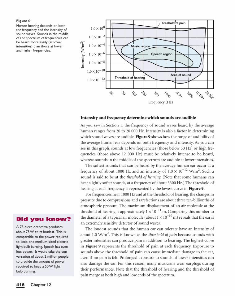
Intensity and frequency determine which sounds are audible
As you saw in Section 1, the frequency of sound waves heard by the average
human ranges from 20 to 20 000 Hz. Intensity is also a factor in determining
which sound waves are audible. Figure 9 shows how the range of audibility of
the average human ear depends on both frequency and intensity. As you can
see in this graph, sounds at low frequencies (those below 50 Hz) or high fre-
quencies (those above 12 000 Hz) must be relatively intense to be heard,
whereas sounds in the middle of the spectrum are audible at lower intensities.
The softest sounds that can be heard by the average human ear occur at a
frequency of about 1000 Hz and an intensity of 1.0 × 10⁻¹² W/m2. Such a
sound is said to be at the threshold of hearing. (Note that some humans can
hear slightly softer sounds, at a frequency of about 3300 Hz.) The threshold of
hearing at each frequency is represented by the lowest curve in Figure 9.For frequencies near 1000 Hz and at the threshold of hearing, the changes in
pressure due to compressions and rarefactions are about three ten-billionths of
atmospheric pressure. The maximum displacement of an air molecule at the
threshold of hearing is approximately 1 × 10⁻¹¹ m. Comparing this number to
the diameter of a typical air molecule (about 1 × 10⁻¹⁰ m) reveals that the ear is
an extremely sensitive detector of sound waves.
The loudest sounds that the human ear can tolerate have an intensity of
about 1.0 W/m2. This is known as the threshold of pain because sounds with
greater intensities can produce pain in addition to hearing. The highest curve
in Figure 9 represents the threshold of pain at each frequency. Exposure to
sounds above the threshold of pain can cause immediate damage to the ear,
even if no pain is felt. Prolonged exposure to sounds of lower intensities can
also damage the ear. For this reason, many musicians wear earplugs during
their performances. Note that the threshold of hearing and the threshold of
pain merge at both high and low ends of the spectrum.
Chapter 12416
Inte
nsi
ty (
W/m
2 )
1.0 × 100
1.0 × 10⁻²
1.0 × 10⁻⁴
1.0 × 10⁻⁶
1.0 × 10⁻⁸
1.0 × 10⁻¹⁰
1.0 × 10⁻¹²
20 50 500
Frequency (Hz)
100200
10002000
500010 000
20 000
Threshold of pain
Threshold of hearingArea of sound
Music region
Speech region
Figure 9Human hearing depends on boththe frequency and the intensity ofsound waves. Sounds in the middleof the spectrum of frequencies canbe heard more easily (at lowerintensities) than those at lower and higher frequencies.
A 75-piece orchestra producesabout 75 W at its loudest. This iscomparable to the power requiredto keep one medium-sized electriclight bulb burning. Speech has evenless power. It would take the con-versation of about 2 million peopleto provide the amount of power required to keep a 50 W light bulb burning.
Did you know?
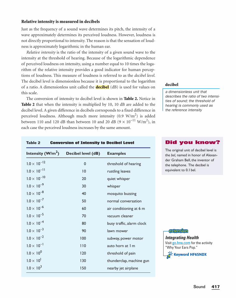
Relative intensity is measured in decibels
Just as the frequency of a sound wave determines its pitch, the intensity of a
wave approximately determines its perceived loudness. However, loudness is
not directly proportional to intensity. The reason is that the sensation of loud-
ness is approximately logarithmic in the human ear.
Relative intensity is the ratio of the intensity of a given sound wave to the
intensity at the threshold of hearing. Because of the logarithmic dependence
of perceived loudness on intensity, using a number equal to 10 times the loga-
rithm of the relative intensity provides a good indicator for human percep-
tions of loudness. This measure of loudness is referred to as the decibel level.
The decibel level is dimensionless because it is proportional to the logarithm
of a ratio. A dimensionless unit called the (dB) is used for values on
this scale.
The conversion of intensity to decibel level is shown in Table 2. Notice in
Table 2 that when the intensity is multiplied by 10, 10 dB are added to the
decibel level. A given difference in decibels corresponds to a fixed difference in
perceived loudness. Although much more intensity (0.9 W/m2) is added
between 110 and 120 dB than between 10 and 20 dB (9 × 10⁻¹¹ W/m2), in
each case the perceived loudness increases by the same amount.
decibel
417Sound
Table 2 Conversion of Intensity to Decibel Level
Intensity (W/m2) Decibel level (dB) Examples
1.0 × 10− 12 0 threshold of hearing
1.0 × 10− 1 1 10 rustling leaves
1.0 × 10− 10 20 quiet whisper
1.0 × 10⁻⁹ 30 whisper
1.0 × 10⁻⁸ 40 mosquito buzzing
1.0 × 10⁻⁷ 50 normal conversation
1.0 × 10⁻⁶ 60 air conditioning at 6 m
1.0 × 10⁻⁵ 70 vacuum cleaner
1.0 × 10⁻⁴ 80 busy traffic, alarm clock
1.0 × 10⁻³ 90 lawn mower
1.0 × 10⁻² 100 subway, power motor
1.0 × 10− 1 1 10 auto horn at 1 m
1.0 × 100 120 threshold of pain
1.0 × 101 130 thunderclap, machine gun
1.0 × 10³ 150 nearby jet airplane
decibel
a dimensionless unit thatdescribes the ratio of two intensi-ties of sound; the threshold ofhearing is commonly used as the reference intensity
The original unit of decibel level isthe bel, named in honor of Alexan-der Graham Bell, the inventor ofthe telephone. The decibel is equivalent to 0. 1 bel.
Did you know?
Integrating HealthVisit go.hrw.com for the activity“Why Your Ears Pop.”
Keyword HF6SNDX
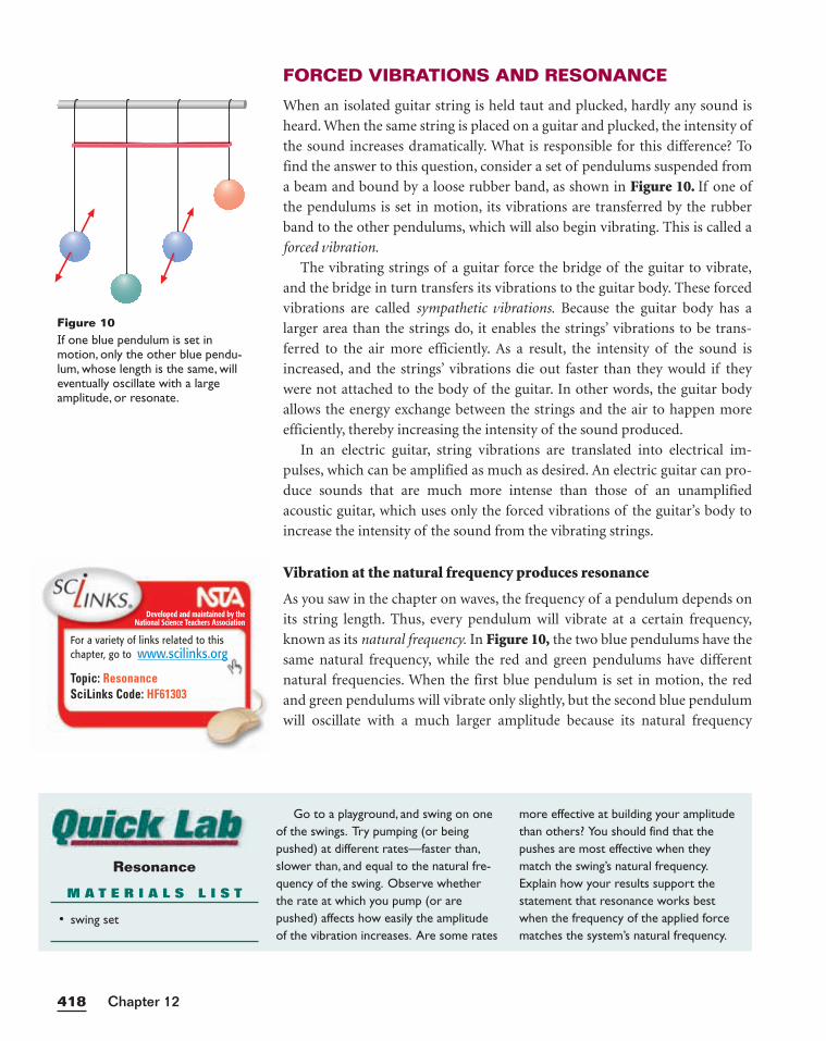
FORCED VIBRATIONS AND RESONANCE
When an isolated guitar string is held taut and plucked, hardly any sound is
heard. When the same string is placed on a guitar and plucked, the intensity of
the sound increases dramatically. What is responsible for this difference? To
find the answer to this question, consider a set of pendulums suspended from
a beam and bound by a loose rubber band, as shown in Figure 10. If one of
the pendulums is set in motion, its vibrations are transferred by the rubber
band to the other pendulums, which will also begin vibrating. This is called a
forced vibration.
The vibrating strings of a guitar force the bridge of the guitar to vibrate,
and the bridge in turn transfers its vibrations to the guitar body. These forced
vibrations are called sympathetic vibrations. Because the guitar body has a
larger area than the strings do, it enables the strings’ vibrations to be trans-
ferred to the air more efficiently. As a result, the intensity of the sound is
increased, and the strings’ vibrations die out faster than they would if they
were not attached to the body of the guitar. In other words, the guitar body
allows the energy exchange between the strings and the air to happen more
efficiently, thereby increasing the intensity of the sound produced.
In an electric guitar, string vibrations are translated into electrical im-
pulses, which can be amplified as much as desired. An electric guitar can pro-
duce sounds that are much more intense than those of an unamplified
acoustic guitar, which uses only the forced vibrations of the guitar’s body to
increase the intensity of the sound from the vibrating strings.
Vibration at the natural frequency produces resonance
As you saw in the chapter on waves, the frequency of a pendulum depends on
its string length. Thus, every pendulum will vibrate at a certain frequency,
known as its natural frequency. In Figure 10, the two blue pendulums have the
same natural frequency, while the red and green pendulums have different
natural frequencies. When the first blue pendulum is set in motion, the red
and green pendulums will vibrate only slightly, but the second blue pendulum
will oscillate with a much larger amplitude because its natural frequency
Chapter 12418
Resonance
M A T E R I A L S L I S T
• swing set
Go to a playground, and swing on oneof the swings. Try pumping (or beingpushed) at different rates—faster than,slower than, and equal to the natural fre-quency of the swing. Observe whetherthe rate at which you pump (or arepushed) affects how easily the amplitudeof the vibration increases. Are some rates
more effective at building your amplitudethan others? You should find that thepushes are most effective when theymatch the swing’s natural frequency.Explain how your results support thestatement that resonance works bestwhen the frequency of the applied forcematches the system’s natural frequency.
Figure 10If one blue pendulum is set inmotion, only the other blue pendu-lum, whose length is the same, willeventually oscillate with a largeamplitude, or resonate.
Developed and maintained by theNational Science Teachers Association
For a variety of links related to thischapter, go to www.scilinks.org
Topic: ResonanceSciLinks Code: HF61303
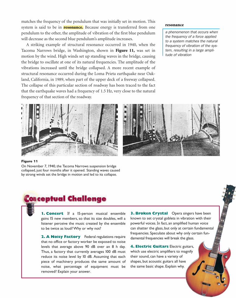
1. Concert If a 15-person musical ensemblegains 15 new members, so that its size doubles, will alistener perceive the music created by the ensembleto be twice as loud? Why or why not?
2. A Noisy Factory Federal regulations requirethat no office or factory worker be exposed to noiselevels that average above 90 dB over an 8 h day.Thus, a factory that currently averages 100 dB mustreduce its noise level by 10 dB. Assuming that eachpiece of machinery produces the same amount ofnoise, what percentage of equipment must beremoved? Explain your answer.
3. Broken Crystal Opera singers have been known to set crystal goblets in vibration with their powerful voices. In fact, an amplified human voice can shatter the glass, but only at certain fundamentalfrequencies. Speculate about why only certain fun-damental frequencies will break the glass.
4. Electric Guitars Electric guitars,which use electric amplifiers to magnifytheir sound, can have a variety ofshapes, but acoustic guitars all havethe same basic shape. Explain why.
matches the frequency of the pendulum that was initially set in motion. This
system is said to be in Because energy is transferred from one
pendulum to the other, the amplitude of vibration of the first blue pendulum
will decrease as the second blue pendulum’s amplitude increases.
A striking example of structural resonance occurred in 1940, when the
Tacoma Narrows bridge, in Washington, shown in Figure 11, was set in
motion by the wind. High winds set up standing waves in the bridge, causing
the bridge to oscillate at one of its natural frequencies. The amplitude of the
vibrations increased until the bridge collapsed. A more recent example of
structural resonance occurred during the Loma Prieta earthquake near Oak-
land, California, in 1989, when part of the upper deck of a freeway collapsed.
The collapse of this particular section of roadway has been traced to the fact
that the earthquake waves had a frequency of 1.5 Hz, very close to the natural
frequency of that section of the roadway.
resonance.
Figure 11On November 7, 1940, the Tacoma Narrows suspension bridgecollapsed, just four months after it opened. Standing waves causedby strong winds set the bridge in motion and led to its collapse.
resonance
a phenomenon that occurs whenthe frequency of a force appliedto a system matches the naturalfrequency of vibration of the sys-tem, resulting in a large ampli-tude of vibration
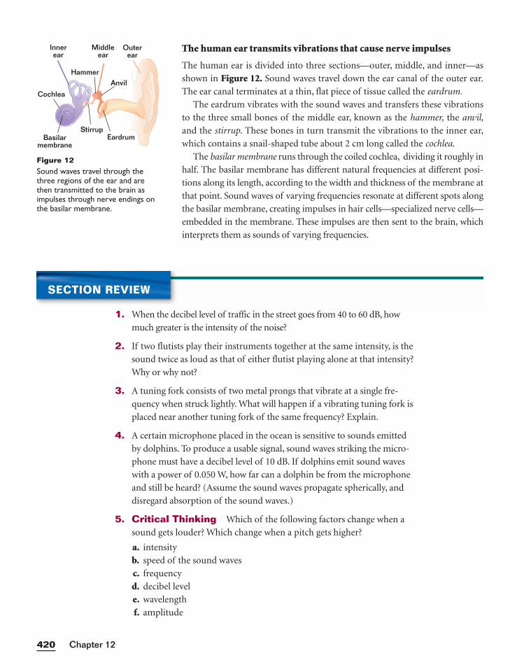
The human ear transmits vibrations that cause nerve impulses
The human ear is divided into three sections—outer, middle, and inner—as
shown in Figure 12. Sound waves travel down the ear canal of the outer ear.
The ear canal terminates at a thin, flat piece of tissue called the eardrum.
The eardrum vibrates with the sound waves and transfers these vibrations
to the three small bones of the middle ear, known as the hammer, the anvil,
and the stirrup. These bones in turn transmit the vibrations to the inner ear,
which contains a snail-shaped tube about 2 cm long called the cochlea.
The basilar membrane runs through the coiled cochlea, dividing it roughly in
half. The basilar membrane has different natural frequencies at different posi-
tions along its length, according to the width and thickness of the membrane at
that point. Sound waves of varying frequencies resonate at different spots along
the basilar membrane, creating impulses in hair cells—specialized nerve cells—
embedded in the membrane. These impulses are then sent to the brain, which
interprets them as sounds of varying frequencies.
Chapter 12420
SECTION REVIEW
1. When the decibel level of traffic in the street goes from 40 to 60 dB, how
much greater is the intensity of the noise?
2. If two flutists play their instruments together at the same intensity, is the
sound twice as loud as that of either flutist playing alone at that intensity?
Why or why not?
3. A tuning fork consists of two metal prongs that vibrate at a single fre-
quency when struck lightly. What will happen if a vibrating tuning fork is
placed near another tuning fork of the same frequency? Explain.
4. A certain microphone placed in the ocean is sensitive to sounds emitted
by dolphins. To produce a usable signal, sound waves striking the micro-
phone must have a decibel level of 10 dB. If dolphins emit sound waves
with a power of 0.050 W, how far can a dolphin be from the microphone
and still be heard? (Assume the sound waves propagate spherically, and
disregard absorption of the sound waves.)
5. Critical Thinking Which of the following factors change when a
sound gets louder? Which change when a pitch gets higher?
a. intensity
b. speed of the sound waves
c. frequency
d. decibel level
e. wavelength
f. amplitude
Middleear
Innerear
Outerear
Eardrum
Cochlea
Basilarmembrane
HammerAnvil
Stirrup
Figure 12Sound waves travel through thethree regions of the ear and arethen transmitted to the brain asimpulses through nerve endings onthe basilar membrane.
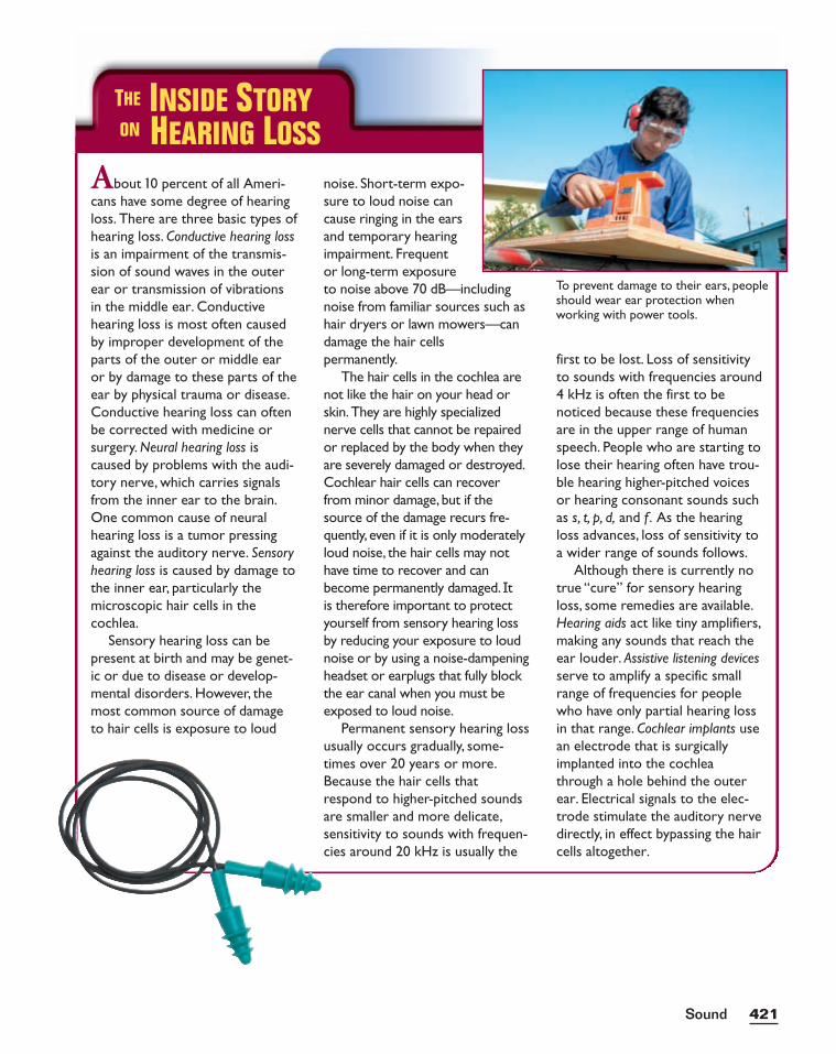
421Sound
About 10 percent of all Ameri-cans have some degree of hearingloss. There are three basic types ofhearing loss. Conductive hearing lossis an impairment of the transmis-sion of sound waves in the outerear or transmission of vibrationsin the middle ear. Conductivehearing loss is most often causedby improper development of theparts of the outer or middle earor by damage to these parts of theear by physical trauma or disease.Conductive hearing loss can oftenbe corrected with medicine orsurgery. Neural hearing loss iscaused by problems with the audi-tory nerve, which carries signalsfrom the inner ear to the brain.One common cause of neuralhearing loss is a tumor pressingagainst the auditory nerve. Sensoryhearing loss is caused by damage tothe inner ear, particularly themicroscopic hair cells in thecochlea.
Sensory hearing loss can bepresent at birth and may be genet-ic or due to disease or develop-mental disorders. However, themost common source of damageto hair cells is exposure to loud
noise. Short-term expo-sure to loud noise cancause ringing in the earsand temporary hearingimpairment. Frequentor long-term exposureto noise above 70 dB—includingnoise from familiar sources such ashair dryers or lawn mowers—candamage the hair cells permanently.
The hair cells in the cochlea arenot like the hair on your head orskin.They are highly specializednerve cells that cannot be repairedor replaced by the body when theyare severely damaged or destroyed.Cochlear hair cells can recoverfrom minor damage, but if thesource of the damage recurs fre-quently, even if it is only moderatelyloud noise, the hair cells may nothave time to recover and canbecome permanently damaged. It is therefore important to protectyourself from sensory hearing lossby reducing your exposure to loudnoise or by using a noise-dampeningheadset or earplugs that fully blockthe ear canal when you must beexposed to loud noise.
Permanent sensory hearing lossusually occurs gradually, some-times over 20 years or more.Because the hair cells thatrespond to higher-pitched soundsare smaller and more delicate,sensitivity to sounds with frequen-cies around 20 kHz is usually the
first to be lost. Loss of sensitivityto sounds with frequencies around4 kHz is often the first to benoticed because these frequenciesare in the upper range of humanspeech. People who are starting tolose their hearing often have trou-ble hearing higher-pitched voicesor hearing consonant sounds suchas s, t, p, d, and f . As the hearingloss advances, loss of sensitivity toa wider range of sounds follows.
Although there is currently notrue “cure” for sensory hearingloss, some remedies are available.Hearing aids act like tiny amplifiers,making any sounds that reach theear louder. Assistive listening devicesserve to amplify a specific smallrange of frequencies for peoplewho have only partial hearing lossin that range. Cochlear implants usean electrode that is surgicallyimplanted into the cochleathrough a hole behind the outerear. Electrical signals to the elec-trode stimulate the auditory nervedirectly, in effect bypassing the haircells altogether.
THE INSIDE STORYON HEARING LOSS
To prevent damage to their ears, peopleshould wear ear protection when working with power tools.
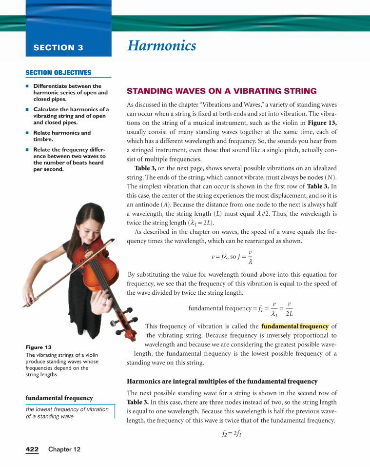
fundamental frequency
the lowest frequency of vibrationof a standing wave
HarmonicsSECTION 3
STANDING WAVES ON A VIBRATING STRING
As discussed in the chapter “Vibrations and Waves,” a variety of standing waves
can occur when a string is fixed at both ends and set into vibration. The vibra-
tions on the string of a musical instrument, such as the violin in Figure 13,usually consist of many standing waves together at the same time, each of
which has a different wavelength and frequency. So, the sounds you hear from
a stringed instrument, even those that sound like a single pitch, actually con-
sist of multiple frequencies.
Table 3, on the next page, shows several possible vibrations on an idealized
string. The ends of the string, which cannot vibrate, must always be nodes (N).
The simplest vibration that can occur is shown in the first row of Table 3. In
this case, the center of the string experiences the most displacement, and so it is
an antinode (A). Because the distance from one node to the next is always half
a wavelength, the string length (L) must equal l1/2. Thus, the wavelength is
twice the string length (l1 = 2L).
As described in the chapter on waves, the speed of a wave equals the fre-
quency times the wavelength, which can be rearranged as shown.
v = fl, so f = lv
By substituting the value for wavelength found above into this equation for
frequency, we see that the frequency of this vibration is equal to the speed of
the wave divided by twice the string length.
fundamental frequency = f1 = lv
1 =
2
v
L
This frequency of vibration is called the of
the vibrating string. Because frequency is inversely proportional to
wavelength and because we are considering the greatest possible wave-
length, the fundamental frequency is the lowest possible frequency of a
standing wave on this string.
Harmonics are integral multiples of the fundamental frequency
The next possible standing wave for a string is shown in the second row of
Table 3. In this case, there are three nodes instead of two, so the string length
is equal to one wavelength. Because this wavelength is half the previous wave-
length, the frequency of this wave is twice that of the fundamental frequency.
f2 = 2f1
fundamental frequency
Chapter 12422
SECTION OBJECTIVES
■ Differentiate between theharmonic series of open andclosed pipes.
■ Calculate the harmonics of avibrating string and of openand closed pipes.
■ Relate harmonics and timbre.
■ Relate the frequency differ-ence between two waves tothe number of beats heardper second.
Figure 13The vibrating strings of a violin produce standing waves whose frequencies depend on the string lengths.
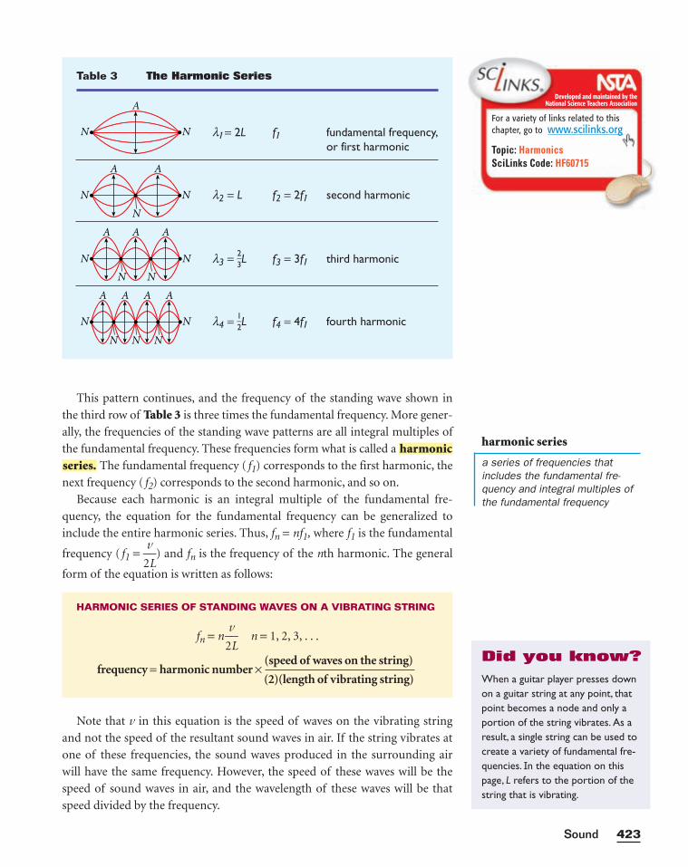
This pattern continues, and the frequency of the standing wave shown in
the third row of Table 3 is three times the fundamental frequency. More gener-
ally, the frequencies of the standing wave patterns are all integral multiples of
the fundamental frequency. These frequencies form what is called a
The fundamental frequency ( f1) corresponds to the first harmonic, the
next frequency ( f2) corresponds to the second harmonic, and so on.
Because each harmonic is an integral multiple of the fundamental fre-
quency, the equation for the fundamental frequency can be generalized to
include the entire harmonic series. Thus, fn = nf1, where f1 is the fundamental
frequency ( f1 = 2
v
L) and fn is the frequency of the nth harmonic. The general
form of the equation is written as follows:
Note that v in this equation is the speed of waves on the vibrating string
and not the speed of the resultant sound waves in air. If the string vibrates at
one of these frequencies, the sound waves produced in the surrounding air
will have the same frequency. However, the speed of these waves will be the
speed of sound waves in air, and the wavelength of these waves will be that
speed divided by the frequency.
HARMONIC SERIES OF STANDING WAVES ON A VIBRATING STRING
fn = n 2
v
L n = 1, 2, 3, . . .
(speed of waves on the string)frequency = harmonic number ×
(2)(length of vibrating string)
series.harmonic
423Sound
Table 3 The Harmonic Series
l1 = 2L f1 fundamental frequency,or first harmonic
l2 = L f2 = 2f1 second harmonic
l3 = 23
L f3 = 3f1 third harmonic
l4 = 12
L f4 = 4f1 fourth harmonic
A
N N
A A
N
N
N
AA A
N N
A A AA
N N
N
N N N
N
harmonic series
a series of frequencies thatincludes the fundamental fre-quency and integral multiples ofthe fundamental frequency
Developed and maintained by theNational Science Teachers Association
For a variety of links related to thischapter, go to www.scilinks.org
Topic: HarmonicsSciLinks Code: HF60715
When a guitar player presses downon a guitar string at any point, thatpoint becomes a node and only aportion of the string vibrates. As aresult, a single string can be used tocreate a variety of fundamental fre-quencies. In the equation on thispage, L refers to the portion of thestring that is vibrating.
Did you know?
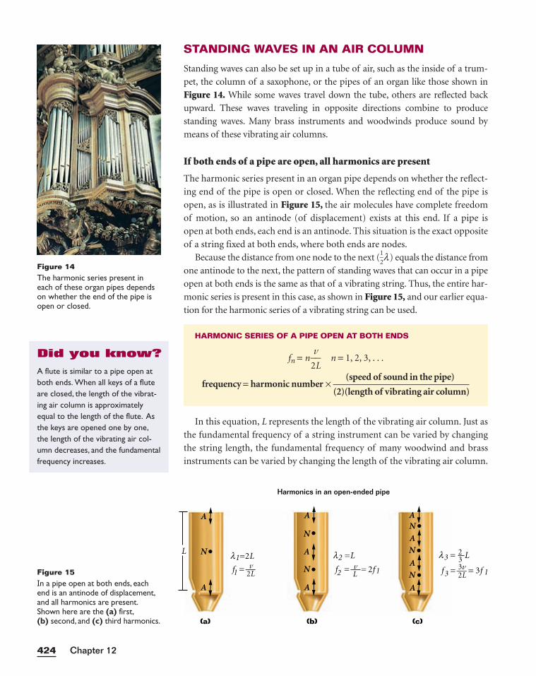
STANDING WAVES IN AN AIR COLUMN
Standing waves can also be set up in a tube of air, such as the inside of a trum-
pet, the column of a saxophone, or the pipes of an organ like those shown in
Figure 14. While some waves travel down the tube, others are reflected back
upward. These waves traveling in opposite directions combine to produce
standing waves. Many brass instruments and woodwinds produce sound by
means of these vibrating air columns.
If both ends of a pipe are open, all harmonics are present
The harmonic series present in an organ pipe depends on whether the reflect-
ing end of the pipe is open or closed. When the reflecting end of the pipe is
open, as is illustrated in Figure 15, the air molecules have complete freedom
of motion, so an antinode (of displacement) exists at this end. If a pipe is
open at both ends, each end is an antinode. This situation is the exact opposite
of a string fixed at both ends, where both ends are nodes.
Because the distance from one node to the next (12
l) equals the distance from
one antinode to the next, the pattern of standing waves that can occur in a pipe
open at both ends is the same as that of a vibrating string. Thus, the entire har-
monic series is present in this case, as shown in Figure 15, and our earlier equa-
tion for the harmonic series of a vibrating string can be used.
In this equation, L represents the length of the vibrating air column. Just as
the fundamental frequency of a string instrument can be varied by changing
the string length, the fundamental frequency of many woodwind and brass
instruments can be varied by changing the length of the vibrating air column.
HARMONIC SERIES OF A PIPE OPEN AT BOTH ENDS
fn = n 2
v
L n = 1, 2, 3, . . .
(speed of sound in the pipe)frequency = harmonic number ×
(2)(length of vibrating air column)
Chapter 12424
Figure 15In a pipe open at both ends, eachend is an antinode of displacement,and all harmonics are present.Shown here are the (a) first,(b) second, and (c) third harmonics.
L
(a) (b) (c)
NN
A
AA
N
A
A
Harmonics in an open-ended pipe
l =2L
1
1
112 32Lv vf =
l =L2
Lf =
l = L3
2L3v32
f = = 3f= 2f
N
N
A
A
N
A
A
Figure 14The harmonic series present ineach of these organ pipes dependson whether the end of the pipe isopen or closed.
A flute is similar to a pipe open atboth ends. When all keys of a fluteare closed, the length of the vibrat-ing air column is approximatelyequal to the length of the flute. Asthe keys are opened one by one,the length of the vibrating air col-umn decreases, and the fundamentalfrequency increases.
Did you know?
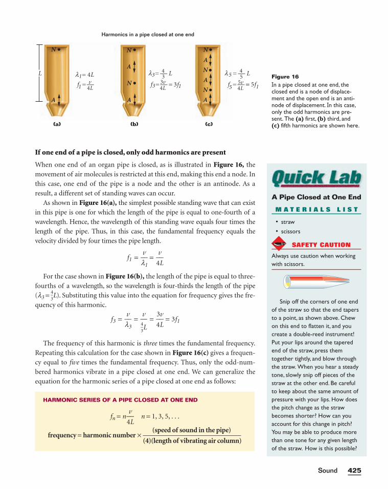
If one end of a pipe is closed, only odd harmonics are present
When one end of an organ pipe is closed, as is illustrated in Figure 16, the
movement of air molecules is restricted at this end, making this end a node. In
this case, one end of the pipe is a node and the other is an antinode. As a
result, a different set of standing waves can occur.
As shown in Figure 16(a), the simplest possible standing wave that can exist
in this pipe is one for which the length of the pipe is equal to one-fourth of a
wavelength. Hence, the wavelength of this standing wave equals four times the
length of the pipe. Thus, in this case, the fundamental frequency equals the
velocity divided by four times the pipe length.
f1 = lv
1 =
4
v
L
For the case shown in Figure 16(b), the length of the pipe is equal to three-
fourths of a wavelength, so the wavelength is four-thirds the length of the pipe
(l3 = 43
L). Substituting this value into the equation for frequency gives the fre-
quency of this harmonic.
f3 = lv
3 = =
4
3
L
v = 3f1
The frequency of this harmonic is three times the fundamental frequency.
Repeating this calculation for the case shown in Figure 16(c) gives a frequen-
cy equal to five times the fundamental frequency. Thus, only the odd-num-
bered harmonics vibrate in a pipe closed at one end. We can generalize the
equation for the harmonic series of a pipe closed at one end as follows:
HARMONIC SERIES OF A PIPE CLOSED AT ONE END
fn = n 4
v
L n = 1, 3, 5, . . .
(speed of sound in the pipe)frequency = harmonic number ×
(4)(length of vibrating air column)
v43
L
425Sound
Figure 16In a pipe closed at one end, theclosed end is a node of displace-ment and the open end is an anti-node of displacement. In this case,only the odd harmonics are pre-sent. The (a) first, (b) third, and(c) fifth harmonics are shown here.
L
(a) (b) (c)
NN
A
A
N
A
A
Harmonics in a pipe closed at one end
1
1
3
3v
N
N
A
N
A
l = 4L
11 5f =
l = L3
3v
4
f =
l = L55v54
f = = 5f= 3f4L4L 4L
A Pipe Closed at One End
M A T E R I A L S L I S T
• straw
• scissors
SAFETY CAUTION
Always use caution when workingwith scissors.
Snip off the corners of one endof the straw so that the end tapersto a point, as shown above. Chewon this end to flatten it, and youcreate a double-reed instrument!Put your lips around the taperedend of the straw, press themtogether tightly, and blow throughthe straw. When you hear a steadytone, slowly snip off pieces of thestraw at the other end. Be carefulto keep about the same amount ofpressure with your lips. How doesthe pitch change as the strawbecomes shorter? How can youaccount for this change in pitch?You may be able to produce morethan one tone for any given lengthof the straw. How is this possible?
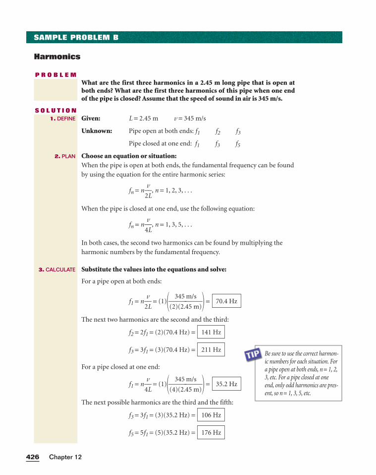
Be sure to use the correct harmon-ic numbers for each situation. Fora pipe open at both ends, n = 1, 2,3, etc. For a pipe closed at oneend, only odd harmonics are pres-ent, so n = 1, 3, 5, etc.
Chapter 12426
SAMPLE PROBLEM B
Harmonics
P R O B L E MWhat are the first three harmonics in a 2.45 m long pipe that is open atboth ends? What are the first three harmonics of this pipe when one endof the pipe is closed? Assume that the speed of sound in air is 345 m/s.
S O L U T I O NGiven: L = 2.45 m v = 345 m/s
Unknown: Pipe open at both ends: f1 f2 f3
Pipe closed at one end: f1 f3 f5
Choose an equation or situation:When the pipe is open at both ends, the fundamental frequency can be found
by using the equation for the entire harmonic series:
fn = n 2
v
L, n = 1, 2, 3, . . .
When the pipe is closed at one end, use the following equation:
fn = n 4
v
L, n = 1, 3, 5, . . .
In both cases, the second two harmonics can be found by multiplying the
harmonic numbers by the fundamental frequency.
Substitute the values into the equations and solve:
For a pipe open at both ends:
f1 = n 2
v
L = (1)�(2
3
)(
4
2
5
.4
m
5
/
m
s
)� =
The next two harmonics are the second and the third:
f2 = 2f1 = (2)(70.4 Hz) =
f3 = 3f1 = (3)(70.4 Hz) =
For a pipe closed at one end:
f1 = n 4
v
L = (1)�(4
3
)(
4
2
5
.4
m
5
/
m
s
)� =
The next possible harmonics are the third and the fifth:
f3 = 3f1 = (3)(35.2 Hz) =
f5 = 5f1 = (5)(35.2 Hz) = 176 Hz
106 Hz
35.2 Hz
211 Hz
141 Hz
70.4 Hz
1. DEFINE
2. PLAN
3. CALCULATE
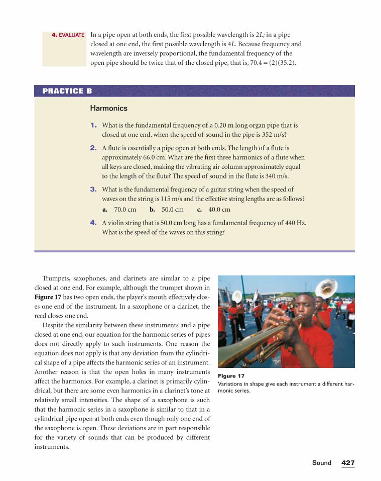
Trumpets, saxophones, and clarinets are similar to a pipe
closed at one end. For example, although the trumpet shown in
Figure 17 has two open ends, the player’s mouth effectively clos-
es one end of the instrument. In a saxophone or a clarinet, the
reed closes one end.
Despite the similarity between these instruments and a pipe
closed at one end, our equation for the harmonic series of pipes
does not directly apply to such instruments. One reason the
equation does not apply is that any deviation from the cylindri-
cal shape of a pipe affects the harmonic series of an instrument.
Another reason is that the open holes in many instruments
affect the harmonics. For example, a clarinet is primarily cylin-
drical, but there are some even harmonics in a clarinet’s tone at
relatively small intensities. The shape of a saxophone is such
that the harmonic series in a saxophone is similar to that in a
cylindrical pipe open at both ends even though only one end of
the saxophone is open. These deviations are in part responsible
for the variety of sounds that can be produced by different
instruments.
427Sound
Figure 17Variations in shape give each instrument a different har-monic series.
PRACTICE B
Harmonics
1. What is the fundamental frequency of a 0.20 m long organ pipe that is
closed at one end, when the speed of sound in the pipe is 352 m/s?
2. A flute is essentially a pipe open at both ends. The length of a flute is
approximately 66.0 cm. What are the first three harmonics of a flute when
all keys are closed, making the vibrating air column approximately equal
to the length of the flute? The speed of sound in the flute is 340 m/s.
3. What is the fundamental frequency of a guitar string when the speed of
waves on the string is 115 m/s and the effective string lengths are as follows?
a. 70.0 cm b. 50.0 cm c. 40.0 cm
4. A violin string that is 50.0 cm long has a fundamental frequency of 440 Hz.
What is the speed of the waves on this string?
In a pipe open at both ends, the first possible wavelength is 2L; in a pipe
closed at one end, the first possible wavelength is 4L. Because frequency and
wavelength are inversely proportional, the fundamental frequency of the
open pipe should be twice that of the closed pipe, that is, 70.4 = (2)(35.2).
4. EVALUATE
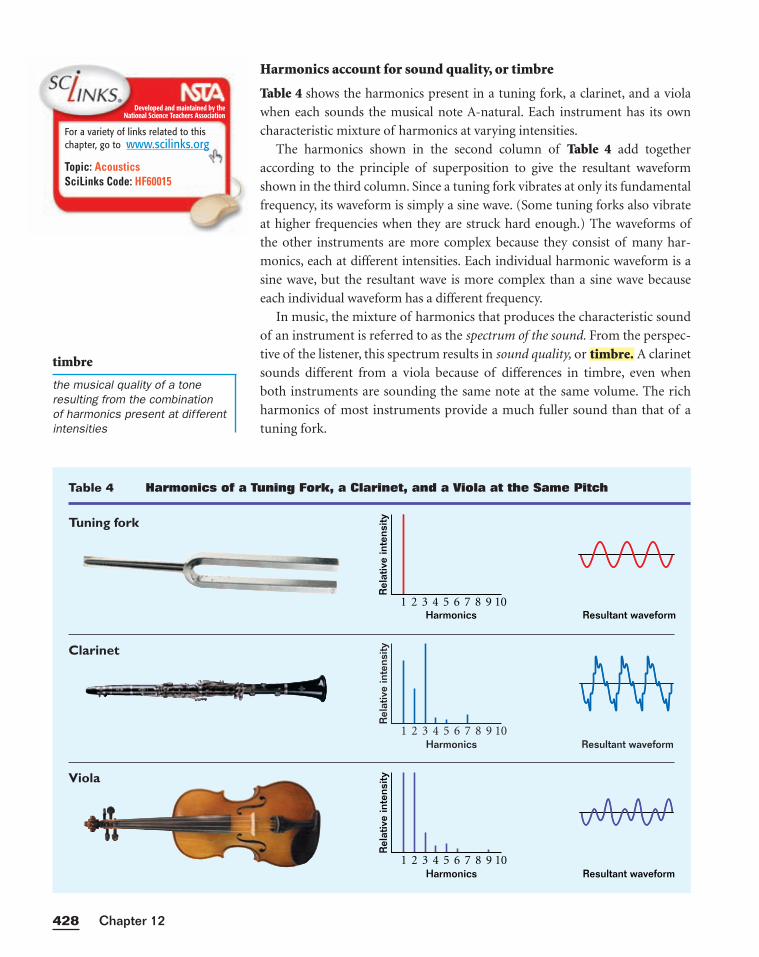
Harmonics account for sound quality, or timbre
Table 4 shows the harmonics present in a tuning fork, a clarinet, and a viola
when each sounds the musical note A-natural. Each instrument has its own
characteristic mixture of harmonics at varying intensities.
The harmonics shown in the second column of Table 4 add together
according to the principle of superposition to give the resultant waveform
shown in the third column. Since a tuning fork vibrates at only its fundamental
frequency, its waveform is simply a sine wave. (Some tuning forks also vibrate
at higher frequencies when they are struck hard enough.) The waveforms of
the other instruments are more complex because they consist of many har-
monics, each at different intensities. Each individual harmonic waveform is a
sine wave, but the resultant wave is more complex than a sine wave because
each individual waveform has a different frequency.
In music, the mixture of harmonics that produces the characteristic sound
of an instrument is referred to as the spectrum of the sound. From the perspec-
tive of the listener, this spectrum results in sound quality, or A clarinet
sounds different from a viola because of differences in timbre, even when
both instruments are sounding the same note at the same volume. The rich
harmonics of most instruments provide a much fuller sound than that of a
tuning fork.
timbre.
Chapter 12428
Developed and maintained by theNational Science Teachers Association
For a variety of links related to thischapter, go to www.scilinks.org
Topic: AcousticsSciLinks Code: HF60015
timbre
the musical quality of a toneresulting from the combination of harmonics present at differentintensities
Table 4 Harmonics of a Tuning Fork, a Clarinet, and a Viola at the Same Pitch
Tuning fork
Clarinet
Viola
Resultant waveformHarmonics
Rel
ativ
e in
tens
ity
1 3 5 7 92 4 6 8 10
Resultant waveformHarmonics
Rel
ativ
e in
tens
ity
1 3 5 7 92 4 6 8 10
Resultant waveformHarmonics
Rel
ativ
e in
tens
ity
1 3 5 7 92 4 6 8 10
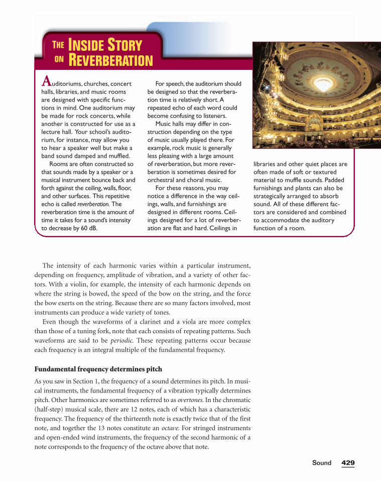
The intensity of each harmonic varies within a particular instrument,
depending on frequency, amplitude of vibration, and a variety of other fac-
tors. With a violin, for example, the intensity of each harmonic depends on
where the string is bowed, the speed of the bow on the string, and the force
the bow exerts on the string. Because there are so many factors involved, most
instruments can produce a wide variety of tones.
Even though the waveforms of a clarinet and a viola are more complex
than those of a tuning fork, note that each consists of repeating patterns. Such
waveforms are said to be periodic. These repeating patterns occur because
each frequency is an integral multiple of the fundamental frequency.
Fundamental frequency determines pitch
As you saw in Section 1, the frequency of a sound determines its pitch. In musi-
cal instruments, the fundamental frequency of a vibration typically determines
pitch. Other harmonics are sometimes referred to as overtones. In the chromatic
(half-step) musical scale, there are 12 notes, each of which has a characteristic
frequency. The frequency of the thirteenth note is exactly twice that of the first
note, and together the 13 notes constitute an octave. For stringed instruments
and open-ended wind instruments, the frequency of the second harmonic of a
note corresponds to the frequency of the octave above that note.
429Sound
Auditoriums, churches, concerthalls, libraries, and music roomsare designed with specific func-tions in mind. One auditorium maybe made for rock concerts, whileanother is constructed for use as alecture hall. Your school’s audito-rium, for instance, may allow youto hear a speaker well but make aband sound damped and muffled.
Rooms are often constructed sothat sounds made by a speaker or amusical instrument bounce back andforth against the ceiling,walls, floor,and other surfaces. This repetitiveecho is called reverberation. Thereverberation time is the amount oftime it takes for a sound’s intensityto decrease by 60 dB.
For speech, the auditorium shouldbe designed so that the reverbera-tion time is relatively short. Arepeated echo of each word couldbecome confusing to listeners.
Music halls may differ in con-struction depending on the type of music usually played there. Forexample, rock music is generallyless pleasing with a large amount of reverberation, but more rever-beration is sometimes desired fororchestral and choral music.
For these reasons, you maynotice a difference in the way ceil-ings, walls, and furnishings aredesigned in different rooms. Ceil-ings designed for a lot of reverber-ation are flat and hard. Ceilings in
libraries and other quiet places areoften made of soft or texturedmaterial to muffle sounds. Paddedfurnishings and plants can also bestrategically arranged to absorbsound. All of these different fac-tors are considered and combinedto accommodate the auditoryfunction of a room.
THE INSIDE STORYON REVERBERATION
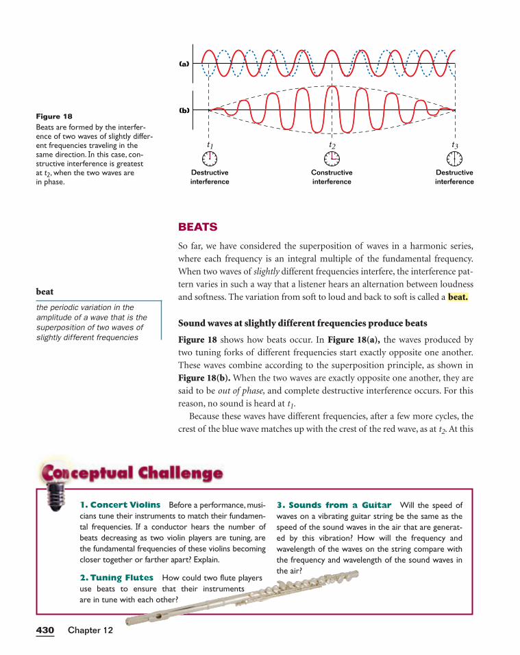
BEATS
So far, we have considered the superposition of waves in a harmonic series,
where each frequency is an integral multiple of the fundamental frequency.
When two waves of slightly different frequencies interfere, the interference pat-
tern varies in such a way that a listener hears an alternation between loudness
and softness. The variation from soft to loud and back to soft is called a
Sound waves at slightly different frequencies produce beats
Figure 18 shows how beats occur. In Figure 18(a), the waves produced by
two tuning forks of different frequencies start exactly opposite one another.
These waves combine according to the superposition principle, as shown in
Figure 18(b). When the two waves are exactly opposite one another, they are
said to be out of phase, and complete destructive interference occurs. For this
reason, no sound is heard at t1.
Because these waves have different frequencies, after a few more cycles, the
crest of the blue wave matches up with the crest of the red wave, as at t2. At this
beat.
Chapter 12430
beat
the periodic variation in theamplitude of a wave that is thesuperposition of two waves ofslightly different frequencies
(a)
Destructiveinterference
Destructiveinterference
Constructiveinterference
(b)
t1 t2 t3
Figure 18Beats are formed by the interfer-ence of two waves of slightly differ-ent frequencies traveling in thesame direction. In this case, con-structive interference is greatest at t2, when the two waves are in phase.
1. Concert Violins Before a performance, musi-cians tune their instruments to match their fundamen-tal frequencies. If a conductor hears the number ofbeats decreasing as two violin players are tuning, arethe fundamental frequencies of these violins becomingcloser together or farther apart? Explain.
2. Tuning Flutes How could two flute playersuse beats to ensure that their instruments are in tune with each other?
3. Sounds from a Guitar Will the speed ofwaves on a vibrating guitar string be the same as thespeed of the sound waves in the air that are generat-ed by this vibration? How will the frequency andwavelength of the waves on the string compare withthe frequency and wavelength of the sound waves inthe air?
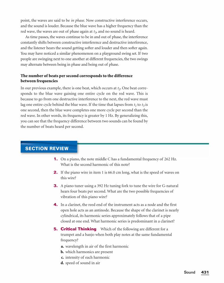
point, the waves are said to be in phase. Now constructive interference occurs,
and the sound is louder. Because the blue wave has a higher frequency than the
red wave, the waves are out of phase again at t3, and no sound is heard.
As time passes, the waves continue to be in and out of phase, the interference
constantly shifts between constructive interference and destructive interference,
and the listener hears the sound getting softer and louder and then softer again.
You may have noticed a similar phenomenon on a playground swing set. If two
people are swinging next to one another at different frequencies, the two swings
may alternate between being in phase and being out of phase.
The number of beats per second corresponds to the differencebetween frequencies
In our previous example, there is one beat, which occurs at t2. One beat corre-
sponds to the blue wave gaining one entire cycle on the red wave. This is
because to go from one destructive interference to the next, the red wave must
lag one entire cycle behind the blue wave. If the time that lapses from t1 to t3 is
one second, then the blue wave completes one more cycle per second than the
red wave. In other words, its frequency is greater by 1 Hz. By generalizing this,
you can see that the frequency difference between two sounds can be found by
the number of beats heard per second.
431Sound
SECTION REVIEW
1. On a piano, the note middle C has a fundamental frequency of 262 Hz.
What is the second harmonic of this note?
2. If the piano wire in item 1 is 66.0 cm long, what is the speed of waves on
this wire?
3. A piano tuner using a 392 Hz tuning fork to tune the wire for G-natural
hears four beats per second. What are the two possible frequencies of
vibration of this piano wire?
4. In a clarinet, the reed end of the instrument acts as a node and the first
open hole acts as an antinode. Because the shape of the clarinet is nearly
cylindrical, its harmonic series approximately follows that of a pipe
closed at one end. What harmonic series is predominant in a clarinet?
5. Critical Thinking Which of the following are different for a
trumpet and a banjo when both play notes at the same fundamental
frequency?
a. wavelength in air of the first harmonic
b. which harmonics are present
c. intensity of each harmonic
d. speed of sound in air
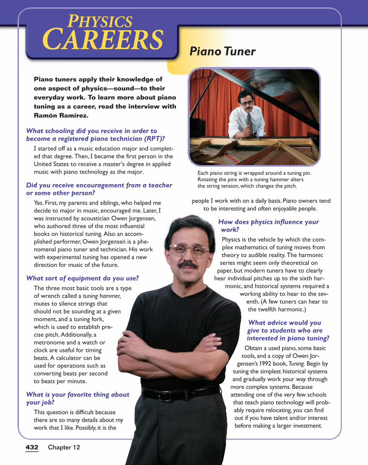
432432
CAREERSPHYSICS
Piano tuners apply their knowledge ofone aspect of physics—sound—to theireveryday work. To learn more about pianotuning as a career, read the interview withRamón Ramírez.
What schooling did you receive in order tobecome a registered piano technician (RPT)?
I started off as a music education major and complet-ed that degree. Then, I became the first person in theUnited States to receive a master's degree in appliedmusic with piano technology as the major.
Did you receive encouragement from a teacheror some other person?
Yes. First, my parents and siblings, who helped medecide to major in music, encouraged me. Later, Iwas instructed by acoustician Owen Jorgensen,who authored three of the most influentialbooks on historical tuning. Also an accom-plished performer, Owen Jorgensen is a phe-nomenal piano tuner and technician. His workwith experimental tuning has opened a newdirection for music of the future.
What sort of equipment do you use?The three most basic tools are a typeof wrench called a tuning hammer,mutes to silence strings thatshould not be sounding at a givenmoment, and a tuning fork,which is used to establish pre-cise pitch. Additionally, ametronome and a watch orclock are useful for timingbeats. A calculator can beused for operations such asconverting beats per secondto beats per minute.
What is your favorite thing aboutyour job?
This question is difficult becausethere are so many details about mywork that I like. Possibly, it is the
people I work with on a daily basis. Piano owners tendto be interesting and often enjoyable people.
How does physics influence yourwork?Physics is the vehicle by which the com-plex mathematics of tuning moves fromtheory to audible reality. The harmonicseries might seem only theoretical on
paper, but modern tuners have to clearlyhear individual pitches up to the sixth har-
monic, and historical systems required aworking ability to hear to the sev-
enth. (A few tuners can hear tothe twelfth harmonic.)
What advice would yougive to students who areinterested in piano tuning?
Obtain a used piano, some basictools, and a copy of Owen Jor-
gensen’s 1992 book, Tuning. Begin bytuning the simplest historical systemsand gradually work your way through
more complex systems. Becauseattending one of the very few schoolsthat teach piano technology will prob-ably require relocating, you can findout if you have talent and/or interestbefore making a larger investment.
Each piano string is wrapped around a tuning pin.Rotating the pins with a tuning hammer altersthe string tension, which changes the pitch.
Chapter 12
Piano Tuner
KEY IDEAS
Section 1 Sound Waves• The frequency of a sound wave determines its pitch.
• The speed of sound depends on the medium.
• The relative motion between the source of waves and an observer creates
an apparent frequency shift known as the Doppler effect.
Section 2 Sound Intensity and Resonance• The sound intensity of a spherical wave is the power per area.
• Sound intensity is inversely proportional to the square of the distance
from the source because the same energy is spread over a larger area.
• Intensity and frequency determine which sounds are audible.
• Decibel level is a measure of relative intensity on a logarithmic scale.
• A given difference in decibels corresponds to a fixed difference in per-
ceived loudness.
• A forced vibration at the natural frequency produces resonance.
• The human ear transmits vibrations that cause nerve impulses. The brain
interprets these impulses as sounds of varying frequencies.
Section 3 Harmonics• Harmonics are integral multiples of the fundamental frequency.
• A vibrating string or a pipe open at both ends produces all harmonics.
• A pipe closed at one end produces only odd harmonics.
• The number and intensity of harmonics account for the sound quality of
an instrument, also known as timbre.
KEY TERMS
compression (p. 408)
rarefaction (p. 408)
pitch (p. 409)
Doppler effect (p. 412)
intensity (p. 414)
decibel (p. 417)
resonance (p. 419)
fundamental frequency (p. 422)
harmonic series (p. 423)
timbre (p. 428)
beat (p. 430)
HighlightsCHAPTER 12
433Sound
Variable Symbols
Quantities Units
sound intensity W/m2 watts/meters squared
decibel level dB decibels
fn frequency of the nth harmonic Hz Hertz = s−1
L length of a vibrating string m metersor an air column
PROBLEM SOLVING
See Appendix D: Equations for a summary of the equationsintroduced in this chapter. Ifyou need more problem-solvingpractice, see Appendix I: Additional Problems.
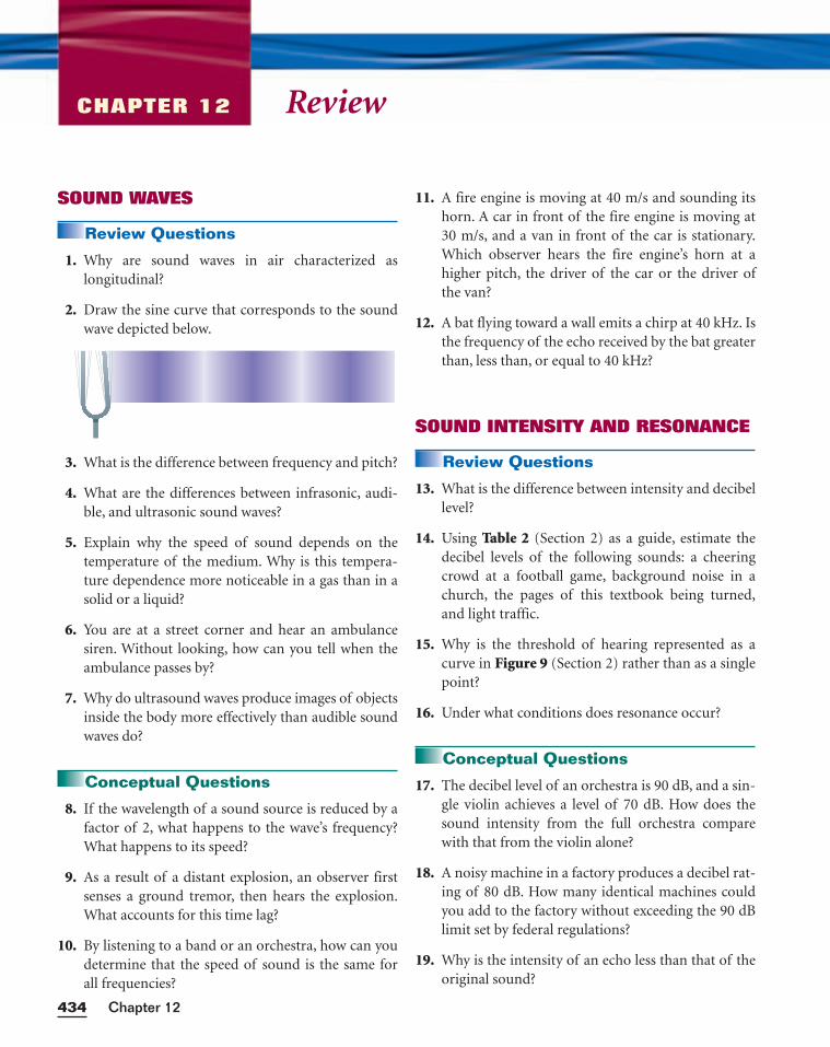
ReviewCHAPTER 12
SOUND WAVES
Review Questions
1. Why are sound waves in air characterized as longitudinal?
2. Draw the sine curve that corresponds to the soundwave depicted below.
3. What is the difference between frequency and pitch?
4. What are the differences between infrasonic, audi-ble, and ultrasonic sound waves?
5. Explain why the speed of sound depends on thetemperature of the medium. Why is this tempera-ture dependence more noticeable in a gas than in asolid or a liquid?
6. You are at a street corner and hear an ambulancesiren. Without looking, how can you tell when theambulance passes by?
7. Why do ultrasound waves produce images of objectsinside the body more effectively than audible soundwaves do?
Conceptual Questions
8. If the wavelength of a sound source is reduced by afactor of 2, what happens to the wave’s frequency?What happens to its speed?
9. As a result of a distant explosion, an observer firstsenses a ground tremor, then hears the explosion.What accounts for this time lag?
10. By listening to a band or an orchestra, how can youdetermine that the speed of sound is the same forall frequencies?
11. A fire engine is moving at 40 m/s and sounding itshorn. A car in front of the fire engine is moving at30 m/s, and a van in front of the car is stationary.Which observer hears the fire engine’s horn at ahigher pitch, the driver of the car or the driver ofthe van?
12. A bat flying toward a wall emits a chirp at 40 kHz. Isthe frequency of the echo received by the bat greaterthan, less than, or equal to 40 kHz?
SOUND INTENSITY AND RESONANCE
Review Questions
13. What is the difference between intensity and decibellevel?
14. Using Table 2 (Section 2) as a guide, estimate thedecibel levels of the following sounds: a cheeringcrowd at a football game, background noise in achurch, the pages of this textbook being turned,and light traffic.
15. Why is the threshold of hearing represented as acurve in Figure 9 (Section 2) rather than as a singlepoint?
16. Under what conditions does resonance occur?
Conceptual Questions
17. The decibel level of an orchestra is 90 dB, and a sin-gle violin achieves a level of 70 dB. How does thesound intensity from the full orchestra comparewith that from the violin alone?
18. A noisy machine in a factory produces a decibel rat-ing of 80 dB. How many identical machines couldyou add to the factory without exceeding the 90 dBlimit set by federal regulations?
19. Why is the intensity of an echo less than that of theoriginal sound?
Chapter 12434
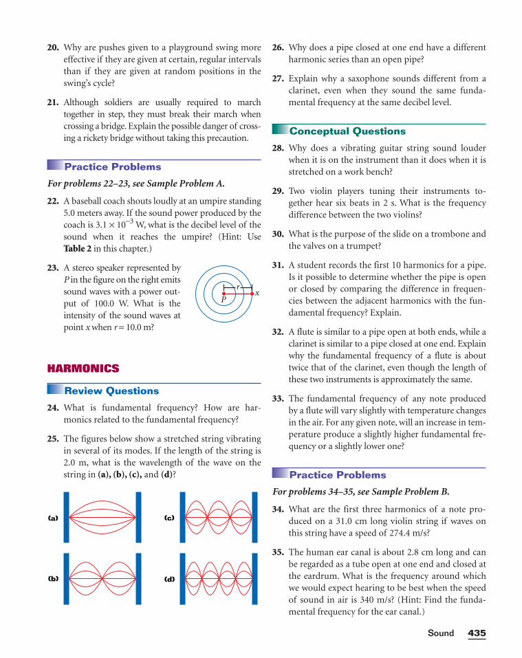
20. Why are pushes given to a playground swing moreeffective if they are given at certain, regular intervalsthan if they are given at random positions in theswing’s cycle?
21. Although soldiers are usually required to marchtogether in step, they must break their march whencrossing a bridge. Explain the possible danger of cross-ing a rickety bridge without taking this precaution.
Practice Problems
For problems 22–23, see Sample Problem A.
22. A baseball coach shouts loudly at an umpire standing5.0 meters away. If the sound power produced by thecoach is 3.1 × 10⁻³ W, what is the decibel level of thesound when it reaches the umpire? (Hint: UseTable 2 in this chapter.)
23. A stereo speaker represented byP in the figure on the right emitssound waves with a power out-put of 100.0 W. What is theintensity of the sound waves atpoint x when r = 10.0 m?
HARMONICS
Review Questions
24. What is fundamental frequency? How are har-monics related to the fundamental frequency?
25. The figures below show a stretched string vibratingin several of its modes. If the length of the string is2.0 m, what is the wavelength of the wave on thestring in (a), (b), (c), and (d)?
(a)
(b)
(c)
(d)
xP
r
26. Why does a pipe closed at one end have a differentharmonic series than an open pipe?
27. Explain why a saxophone sounds different from aclarinet, even when they sound the same funda-mental frequency at the same decibel level.
Conceptual Questions
28. Why does a vibrating guitar string sound louderwhen it is on the instrument than it does when it isstretched on a work bench?
29. Two violin players tuning their instruments to-gether hear six beats in 2 s. What is the frequencydifference between the two violins?
30. What is the purpose of the slide on a trombone andthe valves on a trumpet?
31. A student records the first 10 harmonics for a pipe.Is it possible to determine whether the pipe is openor closed by comparing the difference in frequen-cies between the adjacent harmonics with the fun-damental frequency? Explain.
32. A flute is similar to a pipe open at both ends, while aclarinet is similar to a pipe closed at one end. Explainwhy the fundamental frequency of a flute is abouttwice that of the clarinet, even though the length ofthese two instruments is approximately the same.
33. The fundamental frequency of any note producedby a flute will vary slightly with temperature changesin the air. For any given note, will an increase in tem-perature produce a slightly higher fundamental fre-quency or a slightly lower one?
Practice Problems
For problems 34–35, see Sample Problem B.
34. What are the first three harmonics of a note pro-duced on a 31.0 cm long violin string if waves onthis string have a speed of 274.4 m/s?
35. The human ear canal is about 2.8 cm long and canbe regarded as a tube open at one end and closed atthe eardrum. What is the frequency around whichwe would expect hearing to be best when the speedof sound in air is 340 m/s? (Hint: Find the funda-mental frequency for the ear canal.)
435Sound
MIXED REVIEW
36. A pipe that is open at both ends has a fundamentalfrequency of 320 Hz when the speed of sound in airis 331 m/s.
a. What is the length of this pipe?b. What are the next two harmonics?
37. When two tuning forks of 132 Hz and 137 Hz,respectively, are sounded simultaneously, how manybeats per second are heard?
38. The range of human hearing extends from approxi-mately 20 Hz to 20 000 Hz. Find the wavelengths ofthese extremes when the speed of sound in air isequal to 343 m/s.
Chapter 12436
The first equation applies when the source of sound
is approaching the observer, and the second equa-
tion applies when the source of sound is moving
away from the observer.
In this graphing calculator activity, you will
graph these two equations and will analyze the
graphs to determine the apparent frequencies for
various situations.
Visit go.hrw.com and type in the keyword
HF6SNDX to find this graphing calculator activity.
Refer to Appendix B for instructions on download-
ing the program for this activity.
Doppler EffectAs you learned earlier in this chapter, relative
motion between a source of sound and an observer
can create changes in the observed frequency. This
frequency shift is known as the Doppler effect. The
frequencies heard by the observer can be described
by the following two equations, where f´ represents
the apparent frequency and f represents the actual
frequency.
f � = f �⎯vsoun
v
d
so
−un
v
d
source⎯�
f � = f �⎯vsoun
v
d
so
+un
v
d
source⎯�
39. A dolphin in 25°C sea water emits a sound directedtoward the bottom of the ocean 150 m below. Howmuch time passes before it hears an echo? (SeeTable 1 in this chapter for the speed of the sound.)
40. An open organ pipe is 2.46 m long, and the speed ofthe air in the pipe is 345 m/s.
a. What is the fundamental frequency of thispipe?
b. How many harmonics are possible in the nor-mal hearing range, 20 Hz to 20 000 Hz?
41. The fundamental frequency of an open organ pipecorresponds to the note middle C (f = 261.6 Hz onthe chromatic musical scale). The third harmonic(f3) of another organ pipe that is closed at one endhas the same frequency. Compare the lengths ofthese two pipes.
42. Some studies indicate that the upper frequencylimit of hearing is determined by the diameter ofthe eardrum. The wavelength of the sound waveand the diameter of the eardrum are approximatelyequal at this upper limit. If this is so, what is thediameter of the eardrum of a person capable ofhearing 2.0 × 10⁴ Hz? Assume 378 m/s is the speedof sound in the ear.
43. The decibel level of the noise from a jet aircraft is130 dB when measured 20.0 m from the aircraft.
a. How much sound power does the jet aircraftemit?
b. How much sound power would strike theeardrum of an airport worker 20.0 m from theaircraft? (Use the diameter found in item 42 tocalculate the area of the eardrum.)
437Sound
1. A new airport is being built 750 m from your
school. The noise level 50 m from planes that will
land at the airport is 130 dB. In open spaces, such as
the fields between the school and the airport, the
level decreases by 20 dB each time the distance
increases tenfold. Work in a cooperative group to
research the options for keeping the noise level tol-
erable at the school. How far away would the school
have to be moved to make the sound manageable?
Research the cost of land near your school. What
options are available for soundproofing the school’s
buildings? How expensive are these options? Have
each member in the group present the advantages
and disadvantages of such options.
2. Use soft-drink bottles and water to make a musical
instrument. Adjust the amount of water in different
bottles to create musical notes. Play them as percus-
sion instruments (by tapping the bottles) or as wind
instruments (by blowing over the mouths of indi-
vidual bottles). What media are vibrating in each
case? What affects the fundamental frequency? Use
a microphone and an oscilloscope to analyze your
performance and to demonstrate the effects of tun-
ing your instrument.
3. Interview members of the medical profession to
learn about human hearing. What are some types of
hearing disabilities? How are hearing disabilities
related to disease, age, and occupational or environ-
mental hazards? What procedures and instruments
are used to test hearing? How do hearing aids help?
What are the limitations of hearing aids? Present
your findings to the class.
4. Do research on the types of architectural acoustics
that would affect a restaurant. What are some of
the acoustics problems in places where many peo-
ple gather? How do odd-shaped ceilings, decorative
panels, draperies, and glass windows affect echo
and noise? Find the shortest wavelengths of sounds
that should be absorbed, considering that conver-
sation sounds range from 500 to 5000 Hz. Prepare
a plan or a model of your school cafeteria, and
show what approaches you would use to keep the
level of noise to a minimum.
Alternative Assessment
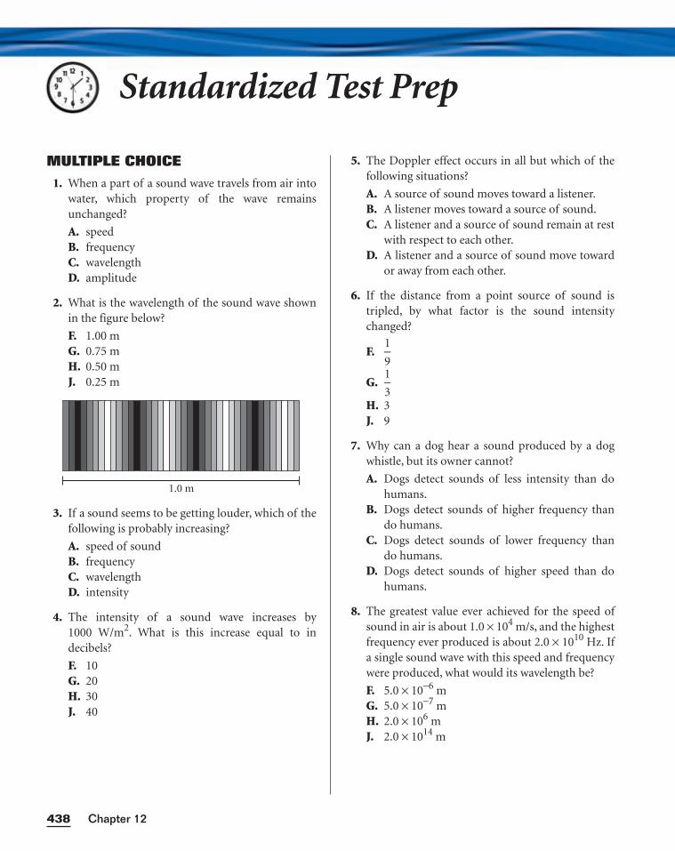
MULTIPLE CHOICE
1. When a part of a sound wave travels from air intowater, which property of the wave remainsunchanged?
A. speedB. frequencyC. wavelengthD. amplitude
2. What is the wavelength of the sound wave shownin the figure below?
F. 1.00 mG. 0.75 mH. 0.50 mJ. 0.25 m
3. If a sound seems to be getting louder, which of thefollowing is probably increasing?
A. speed of soundB. frequencyC. wavelengthD. intensity
4. The intensity of a sound wave increases by1000 W/m2. What is this increase equal to in decibels?
F. 10G. 20H. 30J. 40
1.0 m
5. The Doppler effect occurs in all but which of thefollowing situations?
A. A source of sound moves toward a listener.B. A listener moves toward a source of sound.C. A listener and a source of sound remain at rest
with respect to each other.D. A listener and a source of sound move toward
or away from each other.
6. If the distance from a point source of sound istripled, by what factor is the sound intensitychanged?
F.
G.
H. 3J. 9
7. Why can a dog hear a sound produced by a dogwhistle, but its owner cannot?
A. Dogs detect sounds of less intensity than dohumans.
B. Dogs detect sounds of higher frequency thando humans.
C. Dogs detect sounds of lower frequency thando humans.
D. Dogs detect sounds of higher speed than dohumans.
8. The greatest value ever achieved for the speed ofsound in air is about 1.0 × 10⁴ m/s, and the highestfrequency ever produced is about 2.0 × 10¹⁰ Hz. Ifa single sound wave with this speed and frequencywere produced, what would its wavelength be?
F. 5.0 × 10⁻⁶ mG. 5.0 × 10⁻⁷ mH. 2.0 × 10⁶ mJ. 2.0 × 10¹⁴ m
13
19
Chapter 12438
Standardized Test Prep
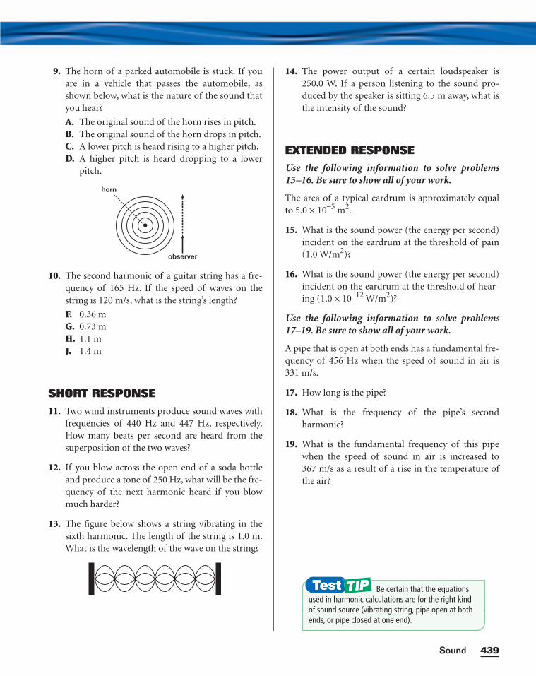
9. The horn of a parked automobile is stuck. If youare in a vehicle that passes the automobile, asshown below, what is the nature of the sound thatyou hear?
A. The original sound of the horn rises in pitch.B. The original sound of the horn drops in pitch.C. A lower pitch is heard rising to a higher pitch.D. A higher pitch is heard dropping to a lower
pitch.
10. The second harmonic of a guitar string has a fre-quency of 165 Hz. If the speed of waves on thestring is 120 m/s, what is the string’s length?
F. 0.36 mG. 0.73 mH. 1.1 mJ. 1.4 m
SHORT RESPONSE
11. Two wind instruments produce sound waves withfrequencies of 440 Hz and 447 Hz, respectively.How many beats per second are heard from thesuperposition of the two waves?
12. If you blow across the open end of a soda bottleand produce a tone of 250 Hz, what will be the fre-quency of the next harmonic heard if you blowmuch harder?
13. The figure below shows a string vibrating in thesixth harmonic. The length of the string is 1.0 m.What is the wavelength of the wave on the string?
horn
observer
14. The power output of a certain loudspeaker is250.0 W. If a person listening to the sound pro-duced by the speaker is sitting 6.5 m away, what isthe intensity of the sound?
EXTENDED RESPONSE
Use the following information to solve problems15–16. Be sure to show all of your work.
The area of a typical eardrum is approximately equalto 5.0 × 10⁻⁵ m2.
15. What is the sound power (the energy per second)incident on the eardrum at the threshold of pain(1.0 W/m2)?
16. What is the sound power (the energy per second)incident on the eardrum at the threshold of hear-ing (1.0 × 10⁻¹² W/m2)?
Use the following information to solve problems17–19. Be sure to show all of your work.
A pipe that is open at both ends has a fundamental fre-quency of 456 Hz when the speed of sound in air is331 m/s.
17. How long is the pipe?
18. What is the frequency of the pipe’s second harmonic?
19. What is the fundamental frequency of this pipewhen the speed of sound in air is increased to367 m/s as a result of a rise in the temperature ofthe air?
439Sound
Be certain that the equationsused in harmonic calculations are for the right kind of sound source (vibrating string, pipe open at bothends, or pipe closed at one end).
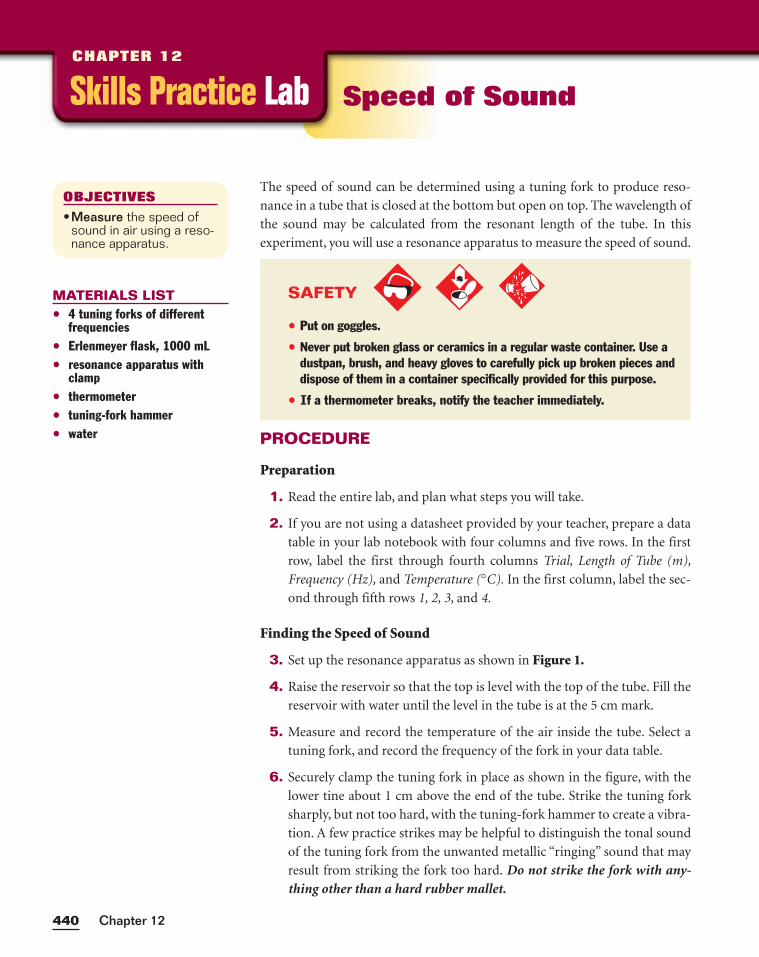
Chapter 12440
The speed of sound can be determined using a tuning fork to produce reso-
nance in a tube that is closed at the bottom but open on top. The wavelength of
the sound may be calculated from the resonant length of the tube. In this
experiment, you will use a resonance apparatus to measure the speed of sound.
PROCEDURE
Preparation
1. Read the entire lab, and plan what steps you will take.
2. If you are not using a datasheet provided by your teacher, prepare a data
table in your lab notebook with four columns and five rows. In the first
row, label the first through fourth columns Trial, Length of Tube (m),
Frequency (Hz), and Temperature (°C). In the first column, label the sec-
ond through fifth rows 1, 2, 3, and 4.
Finding the Speed of Sound
3. Set up the resonance apparatus as shown in Figure 1.
4. Raise the reservoir so that the top is level with the top of the tube. Fill the
reservoir with water until the level in the tube is at the 5 cm mark.
5. Measure and record the temperature of the air inside the tube. Select a
tuning fork, and record the frequency of the fork in your data table.
6. Securely clamp the tuning fork in place as shown in the figure, with the
lower tine about 1 cm above the end of the tube. Strike the tuning fork
sharply, but not too hard, with the tuning-fork hammer to create a vibra-
tion. A few practice strikes may be helpful to distinguish the tonal sound
of the tuning fork from the unwanted metallic “ringing” sound that may
result from striking the fork too hard. Do not strike the fork with any-thing other than a hard rubber mallet.
OBJECTIVES
•Measure the speed ofsound in air using a reso-nance apparatus.
MATERIALS LIST• 4 tuning forks of different
frequencies• Erlenmeyer flask, 1000 mL• resonance apparatus with
clamp• thermometer• tuning-fork hammer• water
Skills Practice LabCHAPTER 12
Speed of Sound
SAFETY
• Put on goggles.
• Never put broken glass or ceramics in a regular waste container. Use adustpan, brush, and heavy gloves to carefully pick up broken pieces anddispose of them in a container specifically provided for this purpose.
• If a thermometer breaks, notify the teacher immediately.
441Sound
7. While the tuning fork is vibrating directly above the tube, slow-
ly lower the reservoir about 20 cm or until you locate the posi-
tion of the reservoir where the resonance is loudest. (Note: To
locate the exact position of the resonance, you may need to
strike the tuning fork again while the water level is falling.)
Raise the reservoir to about 2 cm above the approximate level
where you think the resonance is loudest. Strike the tuning fork
with the tuning fork hammer and carefully lower the reservoir
about 5 cm until you find the exact position of resonance.
8. Using the scale marked on the tube, record the level of the
water in the tube when the resonance is loudest. Record this
level to the nearest millimeter in your data table.
9. Repeat the procedure for several trials, using tuning forks of
different frequencies.
10. Clean up your work area. Put equipment away safely so that it
is ready to be used again. Recycle or dispose of used materials
as directed by your teacher.
ANALYSIS
1. Organizing Data For each trial, calculate the wavelength of the sound
by using the equation for the fundamental wavelength, l = 4L, where L is
the length of the tube.
2. Organizing Data For each trial, find the speed of sound. Use the equa-
tion v = fl, where f is the frequency of the tuning fork.
CONCLUSIONS
3. Evaluating Results Find the accepted value for the speed of sound in air
at room temperature (see Appendix F). Find the average of your results for
the speed of sound, and use the average as the experimental value.
a. Compute the absolute error using the following equation:
absolute error = �experimental − accepted�
b. Compute the relative error using the following equation:
relative error =
4. Analyzing Results Based on your results, is the speed of sound in air at
a given temperature the same for all sounds, or do some sounds move
more quickly or more slowly than other sounds? Explain.
5. Applying Ideas How could you find the speed of sound in air at differ-
ent temperatures?
(experimental − accepted)
accepted
Figure 1Step 7: From the position of great-est resonance, move the reservoirup 2 cm and down again until youfind the exact position.

442
Science • Technology • SocietyScience • Technology • Society
by a food blender or by diesel truck traff ic is about 85
dB. A jet engine heard from a few meters away is about
140 dB.
Have you ever noticed the “headphones” worn by
ground crew at an airport or by workers using chain saws
or jackhammers? In most cases, these are ear protectors
worn to prevent the hearing loss brought on by damage
to the inner ear.
Whose Noise Annoys?The second kind of noise pollution is more controversial
because it involves noises that are considered
annoyances. No one knows for sure how
to measure levels of annoyance, but
sometimes annoying noise becomes
intolerable. Lack of
Suppose you are spending some quiet time alone–
reading, studying, or just daydreaming. Suddenly your
peaceful mood is shattered by the sound of a lawn
mower, loud music, or an airplane taking off. If this has
happened to you, then you have experienced noise
pollution.
Noise is defined as any loud, discordant, or
disagreeable sound, so classifying sounds as noise is
often a matter of personal opinion. When you are at a
party, you might enjoy listening to loud music, but when
you are at home trying to sleep, you may f ind the same
music very disturbing.
There are two kinds of noise pollution, both of which
can result in long-term hearing problems and even
physical damage to the ear. The chapter “Sound”
explains how we receive and interpret sound.
How Can Noise DamageHearing?The small bones and hairlike cells of the inner ear are
delicate and very sensitive to the compression waves we
interpret as sounds. The f irst type of noise pollution
involves noises that are so loud they endanger the
sensitive parts of
the ear. Prolonged
exposure to sounds
of about 85 dB can begin to damage
hearing irreversibly. Certain sounds above 120 dB
can cause immediate damage. The sound level produced
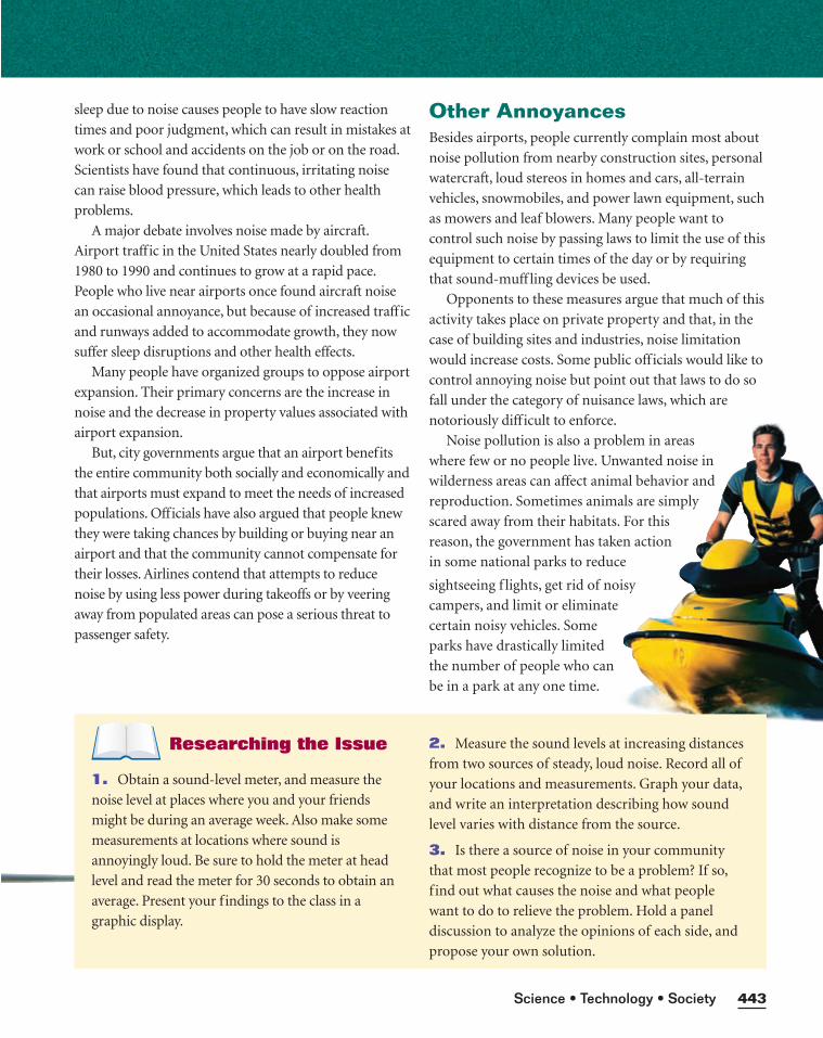
Other AnnoyancesBesides airports, people currently complain most about
noise pollution from nearby construction sites, personal
watercraft, loud stereos in homes and cars, all-terrain
vehicles, snowmobiles, and power lawn equipment, such
as mowers and leaf blowers. Many people want to
control such noise by passing laws to limit the use of this
equipment to certain times of the day or by requiring
that sound-muff ling devices be used.
Opponents to these measures argue that much of this
activity takes place on private property and that, in the
case of building sites and industries, noise limitation
would increase costs. Some public off icials would like to
control annoying noise but point out that laws to do so
fall under the category of nuisance laws, which are
notoriously diff icult to enforce.
Noise pollution is also a problem in areas
where few or no people live. Unwanted noise in
wilderness areas can affect animal behavior and
reproduction. Sometimes animals are simply
scared away from their habitats. For this
reason, the government has taken action
in some national parks to reduce
Science • Technology • Society 443
sightseeing f lights, get rid of noisy
campers, and limit or eliminate
certain noisy vehicles. Some
parks have drastically limited
the number of people who can
be in a park at any one time.
Researching the Issue
1. Obtain a sound-level meter, and measure the
noise level at places where you and your friends
might be during an average week. Also make some
measurements at locations where sound is
annoyingly loud. Be sure to hold the meter at head
level and read the meter for 30 seconds to obtain an
average. Present your findings to the class in a
graphic display.
2. Measure the sound levels at increasing distances
from two sources of steady, loud noise. Record all of
your locations and measurements. Graph your data,
and write an interpretation describing how sound
level varies with distance from the source.
3. Is there a source of noise in your community
that most people recognize to be a problem? If so,
f ind out what causes the noise and what people
want to do to relieve the problem. Hold a panel
discussion to analyze the opinions of each side, and
propose your own solution.
sleep due to noise causes people to have slow reaction
times and poor judgment, which can result in mistakes at
work or school and accidents on the job or on the road.
Scientists have found that continuous, irritating noise
can raise blood pressure, which leads to other health
problems.
A major debate involves noise made by aircraft.
Airport traffic in the United States nearly doubled from
1980 to 1990 and continues to grow at a rapid pace.
People who live near airports once found aircraft noise
an occasional annoyance, but because of increased traffic
and runways added to accommodate growth, they now
suffer sleep disruptions and other health effects.
Many people have organized groups to oppose airport
expansion. Their primary concerns are the increase in
noise and the decrease in property values associated with
airport expansion.
But, city governments argue that an airport benefits
the entire community both socially and economically and
that airports must expand to meet the needs of increased
populations. Officials have also argued that people knew
they were taking chances by building or buying near an
airport and that the community cannot compensate for
their losses. Airlines contend that attempts to reduce
noise by using less power during takeoffs or by veering
away from populated areas can pose a serious threat to
passenger safety.
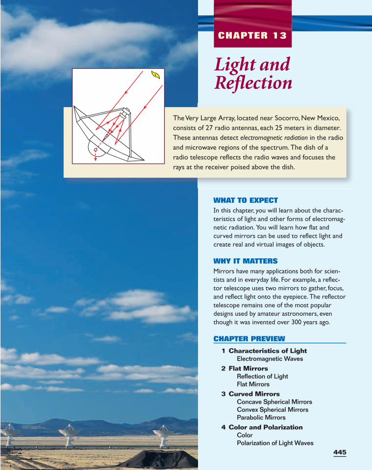
CHAPTER 13
445
The Very Large Array, located near Socorro, New Mexico,consists of 27 radio antennas, each 25 meters in diameter.These antennas detect electromagnetic radiation in the radioand microwave regions of the spectrum. The dish of aradio telescope reflects the radio waves and focuses therays at the receiver poised above the dish.
Light andReflection
WHAT TO EXPECTIn this chapter, you will learn about the charac-teristics of light and other forms of electromag-netic radiation. You will learn how flat andcurved mirrors can be used to reflect light andcreate real and virtual images of objects.
WHY IT MATTERSMirrors have many applications both for scien-tists and in everyday life. For example, a reflec-tor telescope uses two mirrors to gather, focus,and reflect light onto the eyepiece. The reflectortelescope remains one of the most populardesigns used by amateur astronomers, eventhough it was invented over 300 years ago.
CHAPTER PREVIEW
1 Characteristics of LightElectromagnetic Waves
2 Flat MirrorsReflection of LightFlat Mirrors
3 Curved MirrorsConcave Spherical MirrorsConvex Spherical MirrorsParabolic Mirrors
4 Color and PolarizationColorPolarization of Light Waves
Characteristics of LightSECTION 1
ELECTROMAGNETIC WAVES
When most people think of light, they think of the light that they can see.
Some examples include the bright, white light that is produced by a light bulb
or the sun. However, there is more to light than these examples.
When you hold a piece of green glass or plastic in front of a source of white
light, you see green light pass through. This phenomenon is also true for other
colors. What your eyes recognize as “white” light is actually light that can be
separated into six elementary colors of the visible spectrum: red, orange, yel-
low, green, blue, and violet.
If you examine a glass prism, such as the one shown in Figure 1, or any
thick, triangular-shaped piece of glass, you will find that sunlight passes
through the glass and emerges as a rainbowlike band of colors.
The spectrum includes more than visible light
Not all light is visible to the human eye. If you were to use certain types of
photographic film to examine the light dispersed through a prism, you would
find that the film records a much wider spectrum than the one you see. A vari-
ety of forms of radiation—including X rays, microwaves, and radio waves—
have many of the same properties as visible light. The reason is that they are
all examples of
Light has been described as a particle, as a wave, and even as a combination
of the two. Although the current model incorporates aspects of both particle
and wave theories, the wave model is best suited for an introductory discussion
of light, and it is the one that will be used in this section.
electromagnetic waves.
Chapter 13446
SECTION OBJECTIVES
■ Identify the components of the electromagnetic spectrum.
■ Calculate the frequency orwavelength of electromag-netic radiation.
■ Recognize that light has afinite speed.
■ Describe how the brightnessof a light source is affected bydistance.
Figure 1A prism separates light into its component colors.
electromagnetic wave
a wave that consists of oscillat-ing electric and magnetic fields,which radiate outward from thesource at the speed of light
Developed and maintained by theNational Science Teachers Association
For a variety of links related to thischapter, go to www.scilinks.org
Topic: Electromagnetic SpectrumSciLinks Code: HF60482
Electromagnetic waves vary depending on frequency and wavelength
In classical electromagnetic wave theory, light is considered to be a wave com-
posed of oscillating electric and magnetic fields. These fields are perpendicular
to the direction in which the wave moves, as shown in Figure 2. Therefore,
electromagnetic waves are transverse waves. The electric
and magnetic fields are also at right angles to each other.
Electromagnetic waves are distinguished by their differ-
ent frequencies and wavelengths. In visible light, these dif-
ferences in frequency and wavelength account for different
colors. The difference in frequencies and wavelengths also
distinguishes visible light from invisible electromagnetic
radiation, such as X rays.
Types of electromagnetic waves are listed in Table 1.Note the wide range of wavelengths and frequencies.
Although specific ranges are indicated in the table, the elec-
tromagnetic spectrum is, in reality, continuous. There is no
sharp division between one kind of wave and the next.
Some types of waves even have overlapping ranges.
447Light and Reflection
Oscillating magnetic field
Oscillating electric field
Direction of the electromagnetic wave
Figure 2An electromagnetic wave consists of electric and magneticfield waves at right angles to each other.
Table 1 The Electromagnetic Spectrum
Classification Range Applications
radio waves l > 30 cm AM and FM radio; televisionf < 1.0 × 10⁹ Hz
microwaves 30 cm > l > 1 mm radar; atomic and molecular research;1.0 × 10⁹ Hz < f < 3.0 × 10 1 1 Hz aircraft navigation; microwave ovens
infrared (IR) waves 1 mm > l > 700 nm molecular vibrational spectra; infrared 3.0 × 10 1 1 Hz < f < 4.3 × 10 14 Hz photography; physical therapy
visible light 700 nm (red) > l > 400 nm (violet) visible-light photography; optical 4.3 × 10¹⁴ Hz < f < 7.5 × 10¹⁴ Hz microscopy; optical astronomy
ultraviolet (UV) light 400 nm > l > 60 nm sterilization of medical instruments;7.5 × 10 14 Hz < f < 5.0 × 10 15 Hz identification of fluorescent minerals
X rays 60 nm > l > 10−4 nm medical examination of bones, teeth, and 5.0 × 10 15 Hz < f < 3.0 × 10² 1 Hz vital organs; treatment for types of cancer
gamma rays 0.1 nm > l > 10−5 nm examination of thick materials for 3.0 × 10 18 Hz < f < 3.0 × 10²² Hz structural flaws; treatment of types of
cancer; food irradiation
All electromagnetic waves move at the speed of light
All forms of electromagnetic radiation travel at a single high speed in a vacuum.
Early experimental attempts to determine the speed of light failed because this
speed is so great. As experimental techniques improved, especially during the
nineteenth and early twentieth centuries, the speed of light was determined with
increasing accuracy and precision. By the mid-twentieth century, the experimen-
tal error was less than 0.001 percent. The currently accepted value for light travel-
ing in a vacuum is 2.997 924 58 × 108 m/s. Light travels slightly slower in air, with
a speed of 2.997 09 × 108 m/s. For calculations in this book, the value used for
both situations will be 3.00 × 10⁸ m/s.
The relationship between frequency, wavelength, and speed described in
the chapter on vibrations and waves also holds true for light waves.
WAVE SPEED EQUATION
c = fl
speed of light = frequency × wavelength
Chapter 13448
SAMPLE PROBLEM A
Electromagnetic Waves
P R O B L E MThe AM radio band extends from 5.4 × 10⁵ Hz to 1.7 × 10⁶ Hz. What are thelongest and shortest wavelengths in this frequency range?
S O L U T I O NGiven: f1 = 5.4 × 10⁵ Hz f2 = 1.7 × 10⁶ Hz c = 3.00 × 10⁸ m/s
Unknown: l1 = ? l2 = ?
Use the wave speed equation on this page to find the wavelengths:
c = fl l = f
c
l1 = 3
5
.0
.4
0
××
1
1
0
05
8
H
m
z
/s
l2 = 3
1
.0
.7
0
××
1
1
0
06
8
H
m
z
/s
l2 = 1.8 × 10² m
l1 = 5.6 × 10² m CALCULATOR SOLUTION
Although the calculator solutions are555.5555556 m and 176.470588 m,both answers must be rounded to twodigits because the frequencies haveonly two significant figures.
Integrating AstronomyVisit go.hrw.com for the activity“Starlight, Star Heat.”
Keyword HF6LGTX
Waves can be approximated as rays
Consider an ocean wave coming toward the shore. The broad crest of the wave
that is perpendicular to the wave’s motion consists of a line of water particles.
Similarly, another line of water particles forms a low-lying trough in the wave,
and still another line of particles forms the crest of a second wave. In any type
of wave, these lines of particles are called wave fronts.
All the points on the wave front of a plane wave can be treated as point
sources, that is, coming from a source of neglibible size. A few of these points
are shown on the initial wave front in Figure 3. Each of these point sources pro-
duces a circular or spherical secondary wave, or wavelet. The radii of these
wavelets are indicated by the blue arrows in Figure 3. The line that is tangent to
each of these wavelets at some later time determines the new position of the ini-
tial wave front (the new wave front in Figure 3). This approach to analyzing
waves is called Huygens’ principle, named for the physicist Christian Huygens,
who developed it.
Huygens’ principle can be used to derive the properties of any wave
(including light) that interacts with matter, but the same results can be
obtained by treating the propagating wave as a straight line perpendicular to
the wave front. This line is called a ray, and this simplification is called the
ray approximation.
449Light and Reflection
PRACTICE A
Electromagnetic Waves
1. Gamma-ray bursters are objects in the universe that emit pulses of
gamma rays with high energies. The frequency of the most energetic
bursts has been measured at around 3.0 × 10²¹ Hz. What is the wave-
length of these gamma rays?
2. What is the wavelength range for the FM radio band (88 MHz–108 MHz)?
3. Shortwave radio is broadcast between 3.50 and 29.7 MHz. To what range
of wavelengths does this correspond? Why do you suppose this part of
the spectrum is called shortwave radio?
4. What is the frequency of an electromagnetic wave if it has a wavelength
of 1.0 km?
5. The portion of the visible spectrum that appears brightest to the human
eye is around 560 nm in wavelength, which corresponds to yellow-green.
What is the frequency of 560 nm light?
6. What is the frequency of highly energetic ultraviolet radiation that has a
wavelength of 125 nm?
Initial wave front
Tangent line(new wave front)
Figure 3According to Huygens’ principle, awave front can be divided into pointsources. The line tangent to thewavelets from these sources marksthe wave front’s new position.
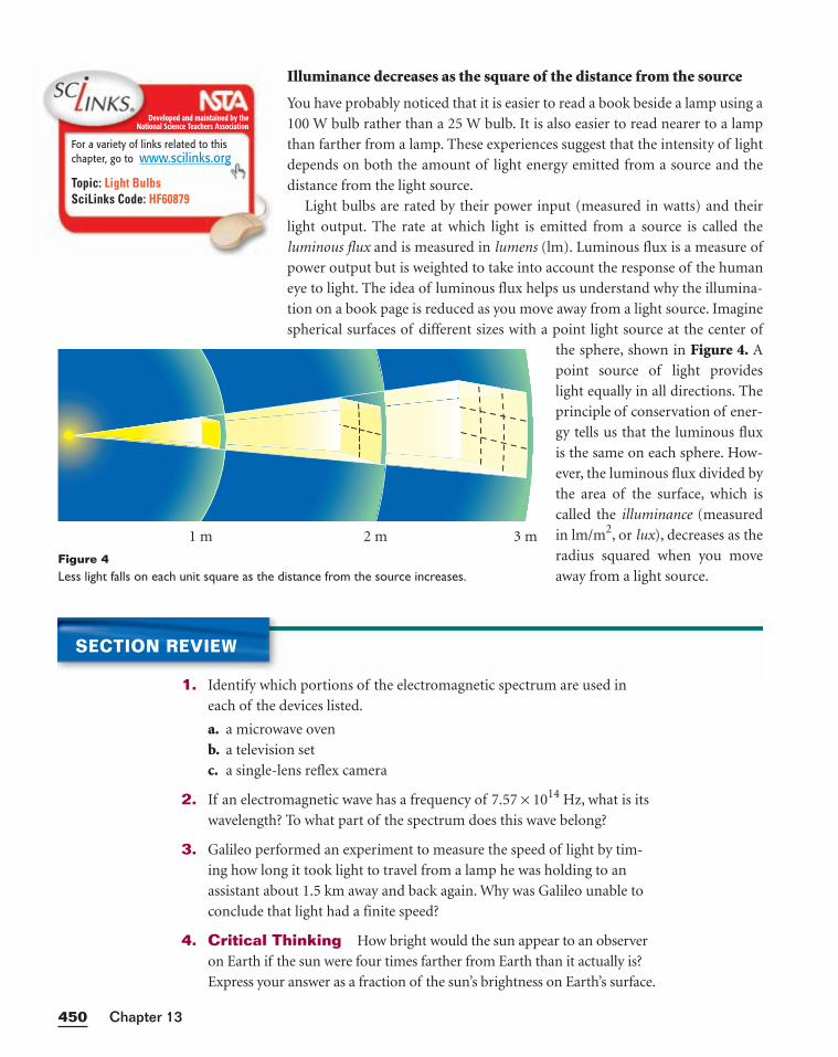
Illuminance decreases as the square of the distance from the source
You have probably noticed that it is easier to read a book beside a lamp using a
100 W bulb rather than a 25 W bulb. It is also easier to read nearer to a lamp
than farther from a lamp. These experiences suggest that the intensity of light
depends on both the amount of light energy emitted from a source and the
distance from the light source.
Light bulbs are rated by their power input (measured in watts) and their
light output. The rate at which light is emitted from a source is called the
luminous flux and is measured in lumens (lm). Luminous flux is a measure of
power output but is weighted to take into account the response of the human
eye to light. The idea of luminous flux helps us understand why the illumina-
tion on a book page is reduced as you move away from a light source. Imagine
spherical surfaces of different sizes with a point light source at the center of
the sphere, shown in Figure 4. A
point source of light provides
light equally in all directions. The
principle of conservation of ener-
gy tells us that the luminous flux
is the same on each sphere. How-
ever, the luminous flux divided by
the area of the surface, which is
called the illuminance (measured
in lm/m2, or lux), decreases as the
radius squared when you move
away from a light source.
Chapter 13450
2 m 3 m1 m
Figure 4Less light falls on each unit square as the distance from the source increases.
SECTION REVIEW
1. Identify which portions of the electromagnetic spectrum are used in
each of the devices listed.
a. a microwave oven
b. a television set
c. a single-lens reflex camera
2. If an electromagnetic wave has a frequency of 7.57 × 10¹⁴ Hz, what is its
wavelength? To what part of the spectrum does this wave belong?
3. Galileo performed an experiment to measure the speed of light by tim-
ing how long it took light to travel from a lamp he was holding to an
assistant about 1.5 km away and back again. Why was Galileo unable to
conclude that light had a finite speed?
4. Critical Thinking How bright would the sun appear to an observer
on Earth if the sun were four times farther from Earth than it actually is?
Express your answer as a fraction of the sun’s brightness on Earth’s surface.
Developed and maintained by theNational Science Teachers Association
For a variety of links related to thischapter, go to www.scilinks.org
Topic: Light BulbsSciLinks Code: HF60879
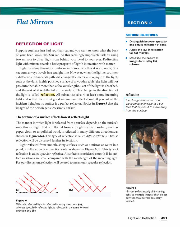
SECTION OBJECTIVES
■ Distinguish between specularand diffuse reflection of light.
■ Apply the law of reflectionfor flat mirrors.
■ Describe the nature ofimages formed by flat mirrors.
451Light and Reflection
Flat Mirrors SECTION 2
REFLECTION OF LIGHT
Suppose you have just had your hair cut and you want to know what the back
of your head looks like. You can do this seemingly impossible task by using
two mirrors to direct light from behind your head to your eyes. Redirecting
light with mirrors reveals a basic property of light’s interaction with matter.
Light traveling through a uniform substance, whether it is air, water, or a
vacuum, always travels in a straight line. However, when the light encounters
a different substance, its path will change. If a material is opaque to the light,
such as the dark, highly polished surface of a wooden table, the light will not
pass into the table more than a few wavelengths. Part of the light is absorbed,
and the rest of it is deflected at the surface. This change in the direction of
the light is called All substances absorb at least some incoming
light and reflect the rest. A good mirror can reflect about 90 percent of the
incident light, but no surface is a perfect reflector. Notice in Figure 5 that the
images of the person get successively darker.
The texture of a surface affects how it reflects light
The manner in which light is reflected from a surface depends on the surface’s
smoothness. Light that is reflected from a rough, textured surface, such as
paper, cloth, or unpolished wood, is reflected in many different directions, as
shown in Figure 6(a). This type of reflection is called diffuse reflection. Diffuse
reflection will be discussed further in Section 4.
Light reflected from smooth, shiny surfaces, such as a mirror or water in a
pond, is reflected in one direction only, as shown in Figure 6(b). This type of
reflection is called specular reflection. A surface is considered smooth if its sur-
face variations are small compared with the wavelength of the incoming light.
For our discussion, reflection will be used to mean only specular reflection.
reflection.
Figure 5Mirrors reflect nearly all incominglight, so multiple images of an objectbetween two mirrors are easilyformed.Figure 6
Diffusely reflected light is reflected in many directions (a),whereas specularly reflected light is reflected in the same forwarddirection only (b).
(a) (b)
reflection
the change in direction of anelectromagnetic wave at a sur-face that causes it to move awayfrom the surface
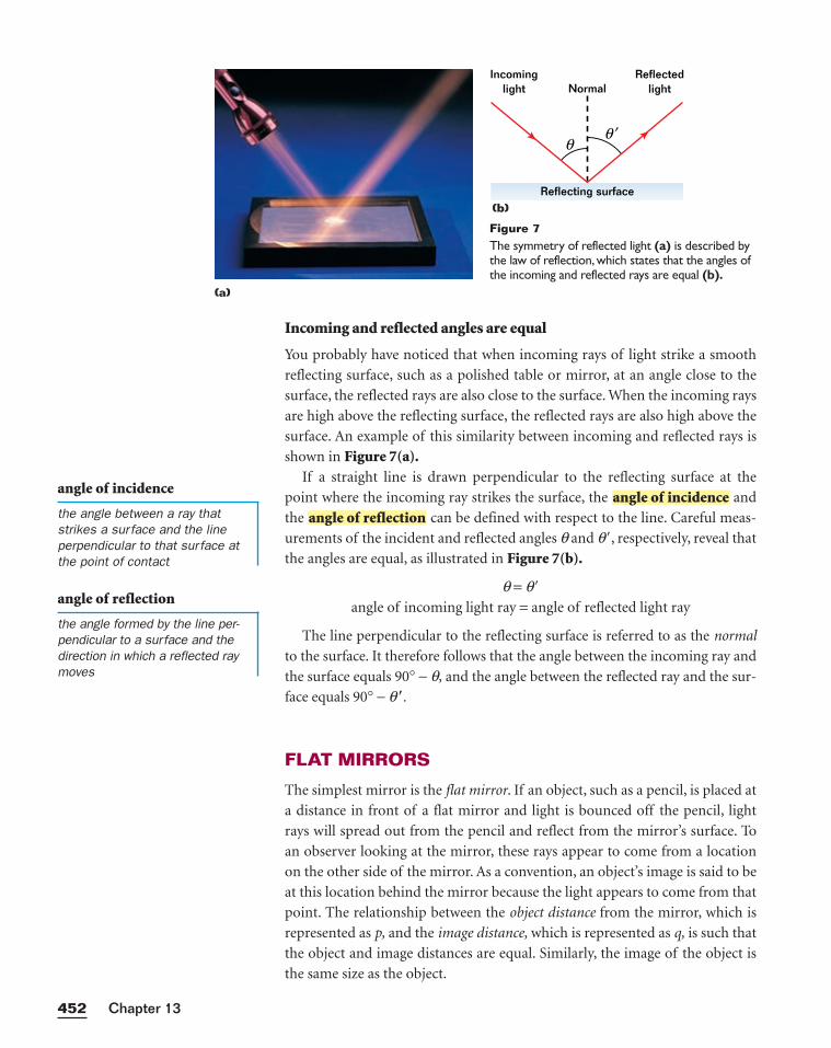
Incoming and reflected angles are equal
You probably have noticed that when incoming rays of light strike a smooth
reflecting surface, such as a polished table or mirror, at an angle close to the
surface, the reflected rays are also close to the surface. When the incoming rays
are high above the reflecting surface, the reflected rays are also high above the
surface. An example of this similarity between incoming and reflected rays is
shown in Figure 7(a).If a straight line is drawn perpendicular to the reflecting surface at the
point where the incoming ray strikes the surface, the and
the can be defined with respect to the line. Careful meas-
urements of the incident and reflected angles q and q�, respectively, reveal that
the angles are equal, as illustrated in Figure 7(b).
q = q�
angle of incoming light ray = angle of reflected light ray
The line perpendicular to the reflecting surface is referred to as the normal
to the surface. It therefore follows that the angle between the incoming ray and
the surface equals 90° − q, and the angle between the reflected ray and the sur-
face equals 90° − q�.
FLAT MIRRORS
The simplest mirror is the flat mirror. If an object, such as a pencil, is placed at
a distance in front of a flat mirror and light is bounced off the pencil, light
rays will spread out from the pencil and reflect from the mirror’s surface. To
an observer looking at the mirror, these rays appear to come from a location
on the other side of the mirror. As a convention, an object’s image is said to be
at this location behind the mirror because the light appears to come from that
point. The relationship between the object distance from the mirror, which is
represented as p, and the image distance, which is represented as q, is such that
the object and image distances are equal. Similarly, the image of the object is
the same size as the object.
angle of reflectionangle of incidence
Chapter 13452
Incominglight Normal
Reflecting surface
Reflectedlight
θθ ′
Figure 7The symmetry of reflected light (a) is described bythe law of reflection, which states that the angles ofthe incoming and reflected rays are equal (b).
(a)
(b)
angle of incidence
the angle between a ray thatstrikes a surface and the lineperpendicular to that surface atthe point of contact
angle of reflection
the angle formed by the line per-pendicular to a surface and thedirection in which a reflected raymoves
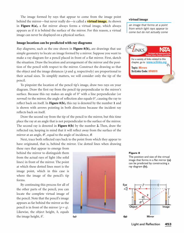
The image formed by rays that appear to come from the image point
behind the mirror—but never really do—is called a As shown
in Figure 8(a), a flat mirror always forms a virtual image, which always
appears as if it is behind the surface of the mirror. For this reason, a virtual
image can never be displayed on a physical surface.
Image location can be predicted with ray diagrams
Ray diagrams, such as the one shown in Figure 8(b), are drawings that use
simple geometry to locate an image formed by a mirror. Suppose you want to
make a ray diagram for a pencil placed in front of a flat mirror. First, sketch
the situation. Draw the location and arrangement of the mirror and the posi-
tion of the pencil with respect to the mirror. Construct the drawing so that
the object and the image distances (p and q, respectively) are proportional to
their actual sizes. To simplify matters, we will consider only the tip of the
pencil.
To pinpoint the location of the pencil tip’s image, draw two rays on your
diagram. Draw the first ray from the pencil tip perpendicular to the mirror’s
surface. Because this ray makes an angle of 0° with a line perpendicular (or
normal) to the mirror, the angle of reflection also equals 0°, causing the ray to
reflect back on itself. In Figure 8(b), this ray is denoted by the number 1 and
is shown with arrows pointing in both directions because the incident ray
reflects back on itself.
Draw the second ray from the tip of the pencil to the mirror, but this time
place the ray at an angle that is not perpendicular to the surface of the mirror.
The second ray is denoted in Figure 8(b) by the number 2. Then, draw the
reflected ray, keeping in mind that it will reflect away from the surface of the
mirror at an angle, q�, equal to the angle of incidence, q.
Next, trace both reflected rays back to the point from which they appear to
have originated, that is, behind the mirror. Use dotted lines when drawing
these rays that appear to emerge from
behind the mirror to distinguish them
from the actual rays of light (the solid
lines) in front of the mirror. The point
at which these dotted lines meet is the
image point, which in this case is
where the image of the pencil’s tip
forms.
By continuing this process for all of
the other parts of the pencil, you can
locate the complete virtual image of
the pencil. Note that the pencil’s image
appears as far behind the mirror as the
pencil is in front of the mirror (p = q).
Likewise, the object height, h, equals
the image height, h′.
virtual image.
453Light and Reflection
Figure 8The position and size of the virtualimage that forms in a flat mirror (a)can be predicted by constructing aray diagram (b).
h
p q
h′
Object
Eye
Image
1
2
Mirror
θθ ′
(b)(a)
virtual image
an image that forms at a pointfrom which light rays appear tocome but do not actually come
Developed and maintained by theNational Science Teachers Association
For a variety of links related to thischapter, go to www.scilinks.org
Topic: MirrorsSciLinks Code: HF60970
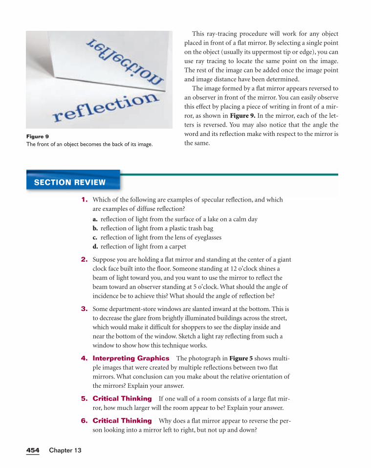
This ray-tracing procedure will work for any object
placed in front of a flat mirror. By selecting a single point
on the object (usually its uppermost tip or edge), you can
use ray tracing to locate the same point on the image.
The rest of the image can be added once the image point
and image distance have been determined.
The image formed by a flat mirror appears reversed to
an observer in front of the mirror. You can easily observe
this effect by placing a piece of writing in front of a mir-
ror, as shown in Figure 9. In the mirror, each of the let-
ters is reversed. You may also notice that the angle the
word and its reflection make with respect to the mirror is
the same.
Chapter 13454
Figure 9The front of an object becomes the back of its image.
SECTION REVIEW
1. Which of the following are examples of specular reflection, and which
are examples of diffuse reflection?
a. reflection of light from the surface of a lake on a calm day
b. reflection of light from a plastic trash bag
c. reflection of light from the lens of eyeglasses
d. reflection of light from a carpet
2. Suppose you are holding a flat mirror and standing at the center of a giant
clock face built into the floor. Someone standing at 12 o’clock shines a
beam of light toward you, and you want to use the mirror to reflect the
beam toward an observer standing at 5 o’clock. What should the angle of
incidence be to achieve this? What should the angle of reflection be?
3. Some department-store windows are slanted inward at the bottom. This is
to decrease the glare from brightly illuminated buildings across the street,
which would make it difficult for shoppers to see the display inside and
near the bottom of the window. Sketch a light ray reflecting from such a
window to show how this technique works.
4. Interpreting Graphics The photograph in Figure 5 shows multi-
ple images that were created by multiple reflections between two flat
mirrors. What conclusion can you make about the relative orientation of
the mirrors? Explain your answer.
5. Critical Thinking If one wall of a room consists of a large flat mir-
ror, how much larger will the room appear to be? Explain your answer.
6. Critical Thinking Why does a flat mirror appear to reverse the per-
son looking into a mirror left to right, but not up and down?
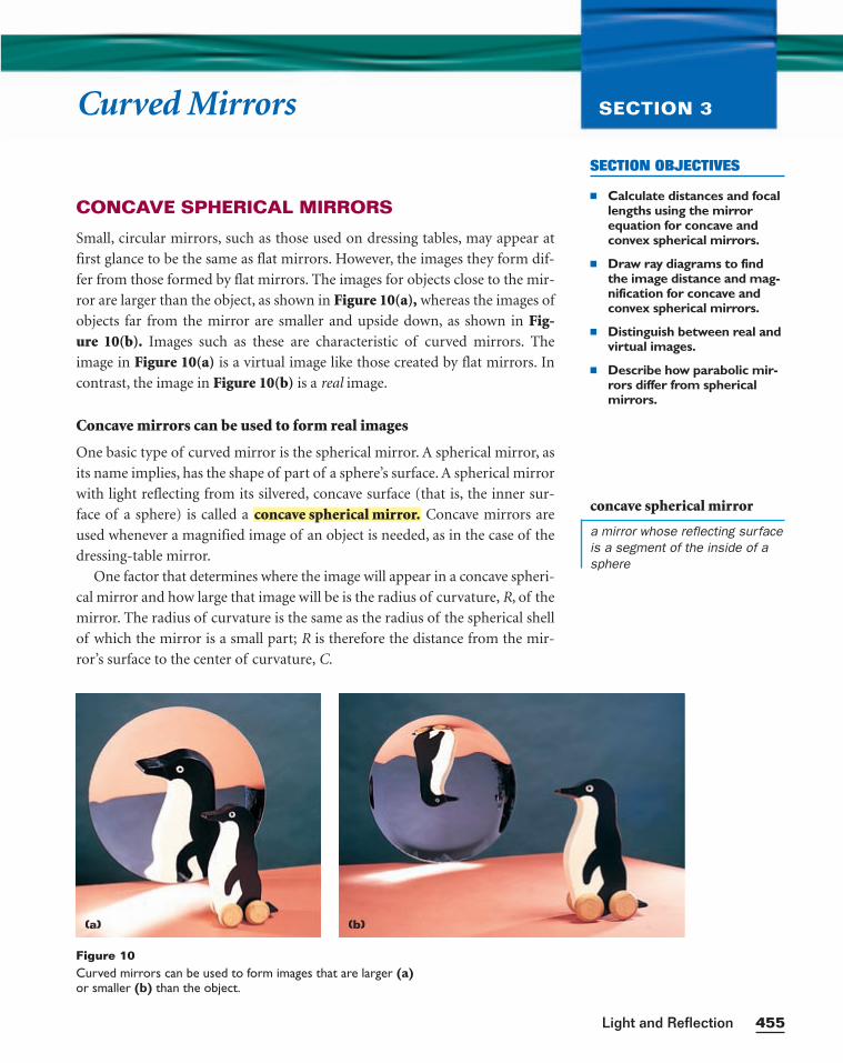
SECTION OBJECTIVES
■ Calculate distances and focallengths using the mirrorequation for concave andconvex spherical mirrors.
■ Draw ray diagrams to findthe image distance and mag-nification for concave andconvex spherical mirrors.
■ Distinguish between real andvirtual images.
■ Describe how parabolic mir-rors differ from sphericalmirrors.
455Light and Reflection
Curved Mirrors SECTION 3
Figure 10Curved mirrors can be used to form images that are larger (a)or smaller (b) than the object.
(a) (b)
CONCAVE SPHERICAL MIRRORS
Small, circular mirrors, such as those used on dressing tables, may appear at
first glance to be the same as flat mirrors. However, the images they form dif-
fer from those formed by flat mirrors. The images for objects close to the mir-
ror are larger than the object, as shown in Figure 10(a), whereas the images of
objects far from the mirror are smaller and upside down, as shown in Fig-ure 10(b). Images such as these are characteristic of curved mirrors. The
image in Figure 10(a) is a virtual image like those created by flat mirrors. In
contrast, the image in Figure 10(b) is a real image.
Concave mirrors can be used to form real images
One basic type of curved mirror is the spherical mirror. A spherical mirror, as
its name implies, has the shape of part of a sphere’s surface. A spherical mirror
with light reflecting from its silvered, concave surface (that is, the inner sur-
face of a sphere) is called a Concave mirrors are
used whenever a magnified image of an object is needed, as in the case of the
dressing-table mirror.
One factor that determines where the image will appear in a concave spheri-
cal mirror and how large that image will be is the radius of curvature, R, of the
mirror. The radius of curvature is the same as the radius of the spherical shell
of which the mirror is a small part; R is therefore the distance from the mir-
ror’s surface to the center of curvature, C.
concave spherical mirror.concave spherical mirror
a mirror whose reflecting surfaceis a segment of the inside of asphere
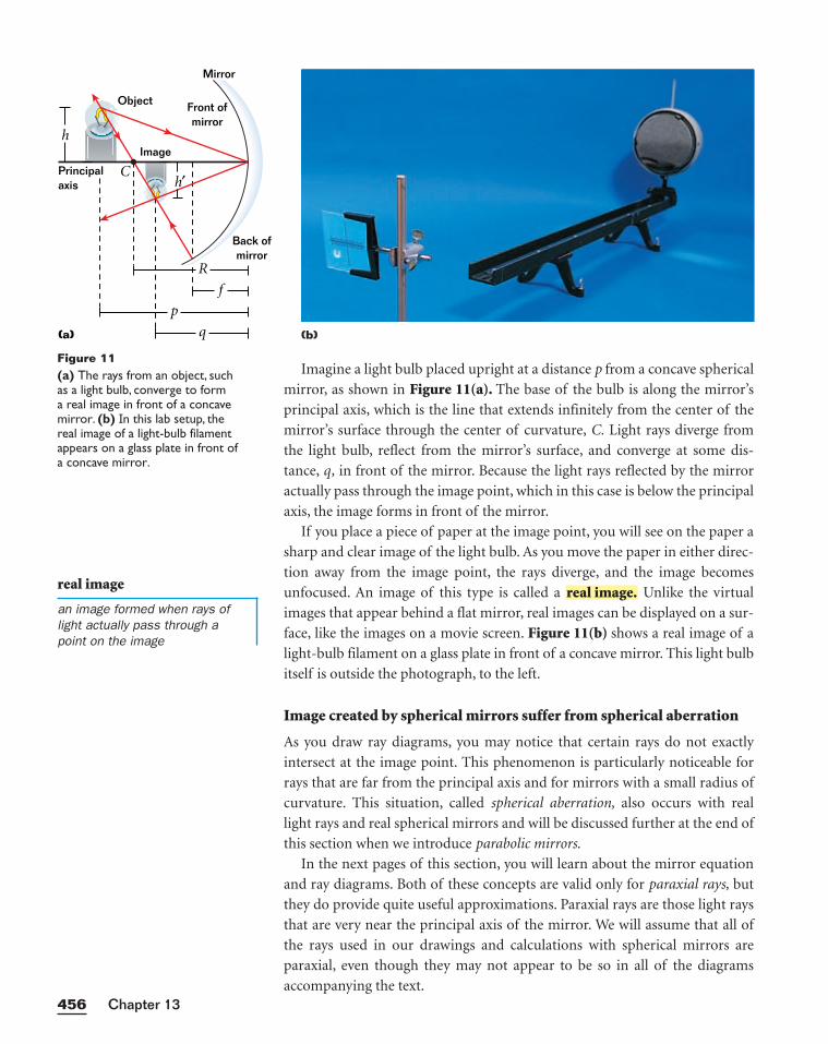
Imagine a light bulb placed upright at a distance p from a concave spherical
mirror, as shown in Figure 11(a). The base of the bulb is along the mirror’s
principal axis, which is the line that extends infinitely from the center of the
mirror’s surface through the center of curvature, C. Light rays diverge from
the light bulb, reflect from the mirror’s surface, and converge at some dis-
tance, q, in front of the mirror. Because the light rays reflected by the mirror
actually pass through the image point, which in this case is below the principal
axis, the image forms in front of the mirror.
If you place a piece of paper at the image point, you will see on the paper a
sharp and clear image of the light bulb. As you move the paper in either direc-
tion away from the image point, the rays diverge, and the image becomes
unfocused. An image of this type is called a Unlike the virtual
images that appear behind a flat mirror, real images can be displayed on a sur-
face, like the images on a movie screen. Figure 11(b) shows a real image of a
light-bulb filament on a glass plate in front of a concave mirror. This light bulb
itself is outside the photograph, to the left.
Image created by spherical mirrors suffer from spherical aberration
As you draw ray diagrams, you may notice that certain rays do not exactly
intersect at the image point. This phenomenon is particularly noticeable for
rays that are far from the principal axis and for mirrors with a small radius of
curvature. This situation, called spherical aberration, also occurs with real
light rays and real spherical mirrors and will be discussed further at the end of
this section when we introduce parabolic mirrors.
In the next pages of this section, you will learn about the mirror equation
and ray diagrams. Both of these concepts are valid only for paraxial rays, but
they do provide quite useful approximations. Paraxial rays are those light rays
that are very near the principal axis of the mirror. We will assume that all of
the rays used in our drawings and calculations with spherical mirrors are
paraxial, even though they may not appear to be so in all of the diagrams
accompanying the text.
real image.
Chapter 13456
(a)
Back ofmirror
Front ofmirror
Mirror
C
h
Principalaxis
Object
Image
p
f
R
q
h′
(b)
Figure 11(a) The rays from an object, such as a light bulb, converge to form a real image in front of a concavemirror. (b) In this lab setup, the real image of a light-bulb filamentappears on a glass plate in front of a concave mirror.
real image
an image formed when rays oflight actually pass through apoint on the image
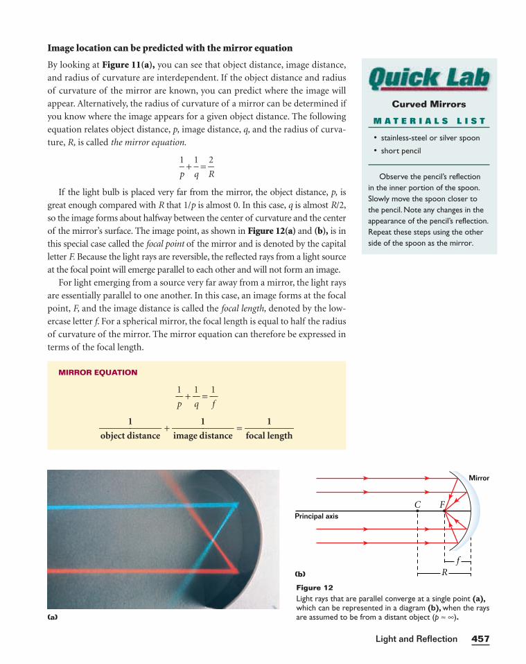
457Light and Reflection
Principal axis
Mirror
C F
fR(b)
Figure 12Light rays that are parallel converge at a single point (a),which can be represented in a diagram (b), when the raysare assumed to be from a distant object (p ≈ ∞).(a)
Curved Mirrors
M A T E R I A L S L I S T
• stainless-steel or silver spoon
• short pencil
Observe the pencil’s reflection in the inner portion of the spoon.Slowly move the spoon closer tothe pencil. Note any changes in theappearance of the pencil’s reflection.Repeat these steps using the otherside of the spoon as the mirror.
Image location can be predicted with the mirror equation
By looking at Figure 11(a), you can see that object distance, image distance,
and radius of curvature are interdependent. If the object distance and radius
of curvature of the mirror are known, you can predict where the image will
appear. Alternatively, the radius of curvature of a mirror can be determined if
you know where the image appears for a given object distance. The following
equation relates object distance, p, image distance, q, and the radius of curva-
ture, R, is called the mirror equation.
p
1 +
1
q =
R
2
If the light bulb is placed very far from the mirror, the object distance, p, is
great enough compared with R that 1/p is almost 0. In this case, q is almost R/2,
so the image forms about halfway between the center of curvature and the center
of the mirror’s surface. The image point, as shown in Figure 12(a) and (b), is in
this special case called the focal point of the mirror and is denoted by the capital
letter F. Because the light rays are reversible, the reflected rays from a light source
at the focal point will emerge parallel to each other and will not form an image.
For light emerging from a source very far away from a mirror, the light rays
are essentially parallel to one another. In this case, an image forms at the focal
point, F, and the image distance is called the focal length, denoted by the low-
ercase letter f. For a spherical mirror, the focal length is equal to half the radius
of curvature of the mirror. The mirror equation can therefore be expressed in
terms of the focal length.
MIRROR EQUATION
p
1 +
1
q =
1
f
object d
1
istance +
image d
1
istance =
focal
1
length
A set of sign conventions for the three variables must be established for use
with the mirror equation. The region in which light rays reflect and form real
images is called the front side of the mirror. The other side, where light rays do
not exist—and where virtual images are formed—is called the back side of the
mirror.
Object and image distances have a positive sign when measured from the
center of the mirror to any point on the mirror’s front side. Distances for
images that form on the back side of the mirror always have a negative sign.
Because the mirrored surface is on the front side of a concave mirror, its focal
length always has a positive sign. The object and image heights are positive
when both are above the principal axis and negative when either is below.
Magnification relates image and object sizes
Unlike flat mirrors, curved mirrors form images that are not the same size as
the object. The measure of how large or small the image is with respect to the
original object’s size is called the magnification of the image.
If you know where an object’s image will form for a given object distance,
you can determine the magnification of the image. Magnification, M , is
defined as the ratio of the height of the bulb’s image to the bulb’s actual
height. M also equals the negative of the ratio of the image distance to the
object distance. If an image is smaller than the object, the magnitude of its
magnification is less than 1. If the image is larger than the object, the magni-
tude of its magnification is greater than 1. Magnification is a unitless quantity.
For an image in front of the mirror, M is negative and the image is upside
down, or inverted, with respect to the object. When the image is behind the
mirror, M is positive and the image is upright with respect to the object. The
conventions for magnification are listed in Table 2.
EQUATION FOR MAGNIFICATION
M = h
h
� = −
p
q
magnification = o
im
bj
a
e
g
c
e
t
h
h
e
e
i
i
g
g
h
h
t
t = −
o
im
bj
a
e
g
c
e
t
d
d
i
i
s
s
t
t
a
a
n
n
c
c
e
e
Chapter 13458
Table 2 Sign Conventions for Magnification
Orientation of image Sign of M Type of imagewith respect to object this applies to
upright + virtual
inverted − real
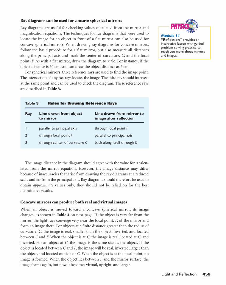
Ray diagrams can be used for concave spherical mirrors
Ray diagrams are useful for checking values calculated from the mirror and
magnification equations. The techniques for ray diagrams that were used to
locate the image for an object in front of a flat mirror can also be used for
concave spherical mirrors. When drawing ray diagrams for concave mirrors,
follow the basic procedure for a flat mirror, but also measure all distances
along the principal axis and mark the center of curvature, C, and the focal
point, F. As with a flat mirror, draw the diagram to scale. For instance, if the
object distance is 50 cm, you can draw the object distance as 5 cm.
For spherical mirrors, three reference rays are used to find the image point.
The intersection of any two rays locates the image. The third ray should intersect
at the same point and can be used to check the diagram. These reference rays
are described in Table 3.
459Light and Reflection
Table 3 Rules for Drawing Reference Rays
Ray Line drawn from object Line drawn from mirror toto mirror image after reflection
1 parallel to principal axis through focal point F
2 through focal point F parallel to principal axis
3 through center of curvature C back along itself through C
PHYSICSPHYSICSModule 14“Reflection” provides aninteractive lesson with guidedproblem-solving practice toteach you more about mirrorsand images.
The image distance in the diagram should agree with the value for q calcu-
lated from the mirror equation. However, the image distance may differ
because of inaccuracies that arise from drawing the ray diagrams at a reduced
scale and far from the principal axis. Ray diagrams should therefore be used to
obtain approximate values only; they should not be relied on for the best
quantitative results.
Concave mirrors can produce both real and virtual images
When an object is moved toward a concave spherical mirror, its image
changes, as shown in Table 4 on next page. If the object is very far from the
mirror, the light rays converge very near the focal point, F, of the mirror and
form an image there. For objects at a finite distance greater than the radius of
curvature, C, the image is real, smaller than the object, inverted, and located
between C and F. When the object is at C, the image is real, located at C, and
inverted. For an object at C, the image is the same size as the object. If the
object is located between C and F, the image will be real, inverted, larger than
the object, and located outside of C. When the object is at the focal point, no
image is formed. When the object lies between F and the mirror surface, the
image forms again, but now it becomes virtual, upright, and larger.
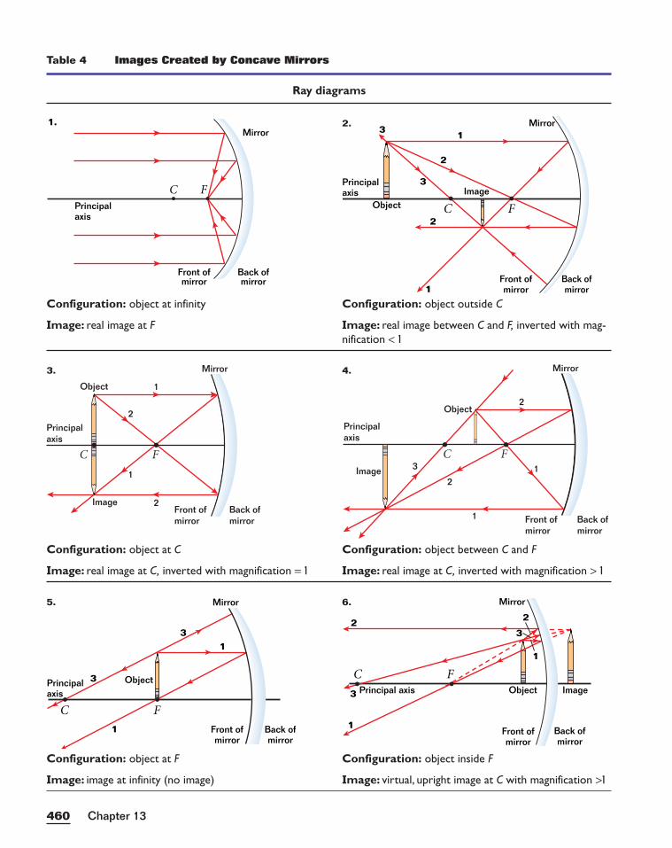
Chapter 13460
Table 4 Images Created by Concave Mirrors
Ray diagrams
1
1
2 2
3
3
Back ofmirror
Front ofmirror
Principal axis ImageObject
Mirror
C F
Back ofmirror
Front ofmirror
Mirror
C
Principalaxis
Object
F
1
3
31
FC
Object
Image
Principalaxis
3
2
2
1
1
Back ofmirror
Front ofmirror
Mirror
FC
Object 1
2
2
1
Image
Principalaxis
Back ofmirror
Front ofmirror
Mirror
Back ofmirror
Front ofmirror
Mirror1
1
2
2
3
3
C
Principalaxis
ObjectImage
F
1.Mirror
Front ofmirror
Back ofmirror
Principalaxis
C F
Configuration: object outside C
Image: real image between C and F, inverted with mag-nification < 1
Configuration: object at infinity
Image: real image at F
Configuration: object between C and F
Image: real image at C, inverted with magnification > 1
Configuration: object at C
Image: real image at C, inverted with magnification = 1
Configuration: object inside F
Image: virtual, upright image at C with magnification >1
Configuration: object at F
Image: image at infinity (no image)
2.
3. 4.
5. 6.
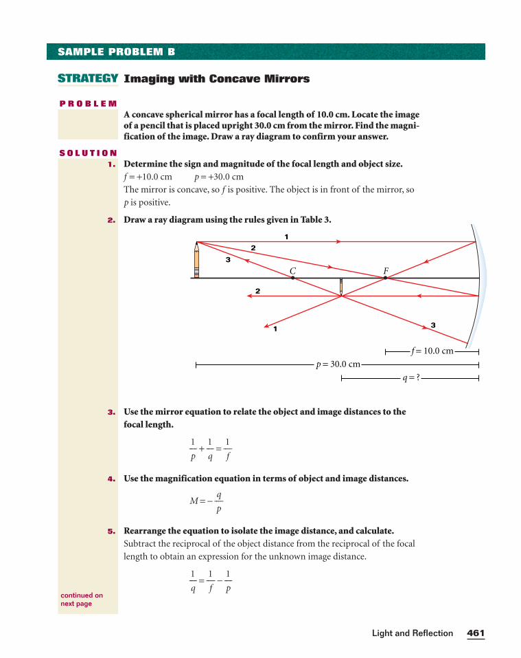
461Light and Reflection
STRATEGY
SAMPLE PROBLEM B
Imaging with Concave Mirrors
P R O B L E MA concave spherical mirror has a focal length of 10.0 cm. Locate the imageof a pencil that is placed upright 30.0 cm from the mirror. Find the magni-fication of the image. Draw a ray diagram to confirm your answer.
S O L U T I O NDetermine the sign and magnitude of the focal length and object size.f = +10.0 cm p = +30.0 cm
The mirror is concave, so f is positive. The object is in front of the mirror, so
p is positive.
Draw a ray diagram using the rules given in Table 3.
Use the mirror equation to relate the object and image distances to thefocal length.
p
1 +
q
1 =
1
f
Use the magnification equation in terms of object and image distances.
M = − p
q
Rearrange the equation to isolate the image distance, and calculate.Subtract the reciprocal of the object distance from the reciprocal of the focal
length to obtain an expression for the unknown image distance.
q
1 =
1
f −
p
1
1.
2.
3.
4.
5.
continued onnext page
q = ?
p = 30.0 cm
f = 10.0 cm
1
1
2
2
3
3
C F
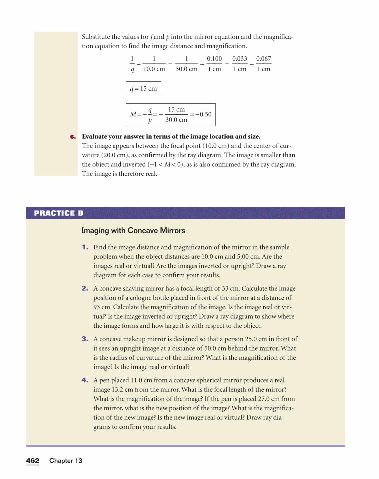
Chapter 13462
Substitute the values for f and p into the mirror equation and the magnifica-
tion equation to find the image distance and magnification.
q
1 =
10.0
1
cm −
30.0
1
cm =
0
1
.1
c
0
m
0 −
0
1
.0
c
3
m
3 =
0
1
.0
c
6
m
7
Evaluate your answer in terms of the image location and size.The image appears between the focal point (10.0 cm) and the center of cur-
vature (20.0 cm), as confirmed by the ray diagram. The image is smaller than
the object and inverted (−1 < M < 0), as is also confirmed by the ray diagram.
The image is therefore real.
M = − p
q = −
3
1
0
5
.0
c
c
m
m = −0.50
q = 15 cm
6.
PRACTICE B
Imaging with Concave Mirrors
1. Find the image distance and magnification of the mirror in the sample
problem when the object distances are 10.0 cm and 5.00 cm. Are the
images real or virtual? Are the images inverted or upright? Draw a ray
diagram for each case to confirm your results.
2. A concave shaving mirror has a focal length of 33 cm. Calculate the image
position of a cologne bottle placed in front of the mirror at a distance of
93 cm. Calculate the magnification of the image. Is the image real or vir-
tual? Is the image inverted or upright? Draw a ray diagram to show where
the image forms and how large it is with respect to the object.
3. A concave makeup mirror is designed so that a person 25.0 cm in front of
it sees an upright image at a distance of 50.0 cm behind the mirror. What
is the radius of curvature of the mirror? What is the magnification of the
image? Is the image real or virtual?
4. A pen placed 11.0 cm from a concave spherical mirror produces a real
image 13.2 cm from the mirror. What is the focal length of the mirror?
What is the magnification of the image? If the pen is placed 27.0 cm from
the mirror, what is the new position of the image? What is the magnifica-
tion of the new image? Is the new image real or virtual? Draw ray dia-
grams to confirm your results.
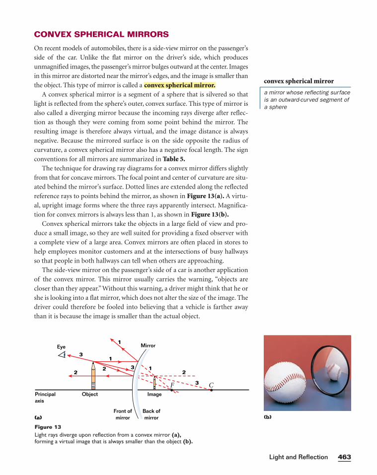
CONVEX SPHERICAL MIRRORS
On recent models of automobiles, there is a side-view mirror on the passenger’s
side of the car. Unlike the flat mirror on the driver’s side, which produces
unmagnified images, the passenger’s mirror bulges outward at the center. Images
in this mirror are distorted near the mirror’s edges, and the image is smaller than
the object. This type of mirror is called a
A convex spherical mirror is a segment of a sphere that is silvered so that
light is reflected from the sphere’s outer, convex surface. This type of mirror is
also called a diverging mirror because the incoming rays diverge after reflec-
tion as though they were coming from some point behind the mirror. The
resulting image is therefore always virtual, and the image distance is always
negative. Because the mirrored surface is on the side opposite the radius of
curvature, a convex spherical mirror also has a negative focal length. The sign
conventions for all mirrors are summarized in Table 5.The technique for drawing ray diagrams for a convex mirror differs slightly
from that for concave mirrors. The focal point and center of curvature are situ-
ated behind the mirror’s surface. Dotted lines are extended along the reflected
reference rays to points behind the mirror, as shown in Figure 13(a). A virtu-
al, upright image forms where the three rays apparently intersect. Magnifica-
tion for convex mirrors is always less than 1, as shown in Figure 13(b).Convex spherical mirrors take the objects in a large field of view and pro-
duce a small image, so they are well suited for providing a fixed observer with
a complete view of a large area. Convex mirrors are often placed in stores to
help employees monitor customers and at the intersections of busy hallways
so that people in both hallways can tell when others are approaching.
The side-view mirror on the passenger’s side of a car is another application
of the convex mirror. This mirror usually carries the warning, “objects are
closer than they appear.” Without this warning, a driver might think that he or
she is looking into a flat mirror, which does not alter the size of the image. The
driver could therefore be fooled into believing that a vehicle is farther away
than it is because the image is smaller than the actual object.
convex spherical mirror.
463Light and Reflection
Principalaxis
ImageObject
Eye
CF
1
1
2
3
3
Back ofmirror
Front ofmirror
Mirror
(a)
2
3
12
Figure 13Light rays diverge upon reflection from a convex mirror (a),forming a virtual image that is always smaller than the object (b).
convex spherical mirror
a mirror whose reflecting surfaceis an outward-curved segment ofa sphere
(b)
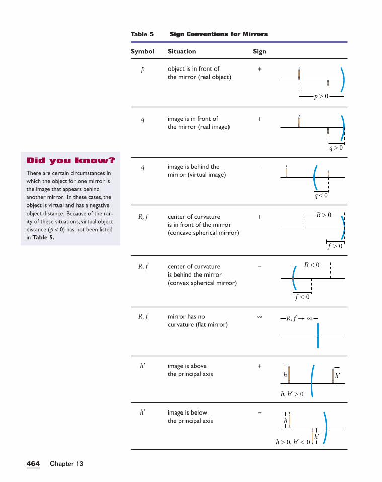
Chapter 13464
Table 5 Sign Conventions for Mirrors
Symbol Situation Sign
p object is in front of +the mirror (real object)
q image is in front of +the mirror (real image)
q image is behind the −mirror (virtual image)
R, f center of curvature +is in front of the mirror(concave spherical mirror)
R, f center of curvature −is behind the mirror(convex spherical mirror)
R, f mirror has no ∞curvature (flat mirror)
h� image is above +the principal axis
h� image is below −the principal axis h
h′h > 0, h′ < 0
h
h, h′ > 0
h′
R, f ∞
p > 0
q > 0
q < 0
f > 0
R > 0
f < 0
R < 0
There are certain circumstances inwhich the object for one mirror isthe image that appears behindanother mirror. In these cases, theobject is virtual and has a negativeobject distance. Because of the rar-ity of these situations, virtual objectdistance (p < 0) has not been listedin Table 5.
Did you know?
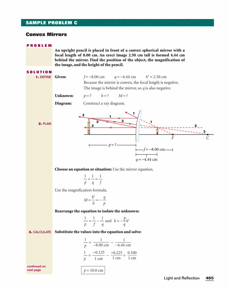
465Light and Reflection
SAMPLE PROBLEM C
Convex Mirrors
P R O B L E MAn upright pencil is placed in front of a convex spherical mirror with afocal length of 8.00 cm. An erect image 2.50 cm tall is formed 4.44 cmbehind the mirror. Find the position of the object, the magnification ofthe image, and the height of the pencil.
S O L U T I O NGiven: f = −8.00 cm q = −4.44 cm h� = 2.50 cm
Because the mirror is convex, the focal length is negative.
The image is behind the mirror, so q is also negative.
Unknown: p = ? h = ? M = ?
Diagram: Construct a ray diagram.
Choose an equation or situation: Use the mirror equation.
⎯⎯p
1⎯⎯ + ⎯⎯
q
1⎯⎯ = ⎯⎯
1
f⎯⎯
Use the magnification formula.
M = ⎯h
h
�⎯ = − ⎯⎯
p
q⎯⎯
Rearrange the equation to isolate the unknown:
⎯⎯p
1⎯⎯⎯ = ⎯⎯
1
f⎯⎯ − ⎯⎯⎯
1
q⎯⎯ and h = − ⎯⎯
p
q⎯⎯h�
Substitute the values into the equation and solve:
⎯⎯p
1⎯⎯⎯ = �−8.0
10 cm� − �−4.44
1cm
�
⎯p
1⎯⎯⎯ = ⎯
−1
0.
c
1
m
25⎯ − �
−10.
c2m25
� = �01.1c0m0
�
p = 10.0 cm
1. DEFINE
2. PLAN
3. CALCULATE
continued onnext page
CF
11
22 3
q = −4.44 cm
f = −8.00 cmp = ?
2
3
1
3
Chapter 13466
Substitute the values for p and q to find the magnification of the image.
M = −�pq
� = − −1
4
0
.
.
4
0
4
c
c
m
m
Substitute the values for p, q, and h� to find the height of the object.
h = − p
qh� = − �−
140..404ccmm
� (2.50 cm)
h = 5.63 cm
M = 0.444
PRACTICE C
Convex Mirrors
1. The image of a crayon appears to be 23.0 cm behind the surface of a con-
vex mirror and is 1.70 cm tall. If the mirror’s focal length is 46.0 cm, how
far in front of the mirror is the crayon positioned? What is the magnifi-
cation of the image? Is the image virtual or real? Is the image inverted or
upright? How tall is the actual crayon?
2. A convex mirror with a focal length of 0.25 m forms a 0.080 m tall image of
an automobile at a distance of 0.24 m behind the mirror. What is the mag-
nification of the image? Where is the car located, and what is its height? Is
the image real or virtual? Is the image upright or inverted?
3. A convex mirror of focal length 33 cm forms an image of a soda bottle
at a distance of 19 cm behind the mirror. If the height of the image is
7.0 cm, where is the object located, and how tall is it? What is the magni-
fication of the image? Is the image virtual or real? Is the image inverted
or upright? Draw a ray diagram to confirm your results.
4. A convex mirror with a radius of curvature of 0.550 m is placed above
the aisles in a store. Determine the image distance and magnification of a
customer lying on the floor 3.1 m below the mirror. Is the image virtual
or real? Is the image inverted or upright?
5. A spherical glass ornament is 6.00 cm in diameter. If an object is placed
10.5 cm away from the ornament, where will its image form? What is the
magnification? Is the image virtual or real? Is the image inverted or upright?
6. A candle is 49 cm in front of a convex spherical mirror that has a focal
length of 35 cm. What are the image distance and magnification? Is the
image virtual or real? Is the image inverted or upright? Draw a ray dia-
gram to confirm your results.
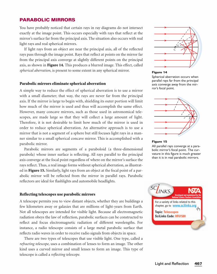
PARABOLIC MIRRORS
You have probably noticed that certain rays in ray diagrams do not intersect
exactly at the image point. This occurs especially with rays that reflect at the
mirror’s surface far from the principal axis. The situation also occurs with real
light rays and real spherical mirrors.
If light rays from an object are near the principal axis, all of the reflected
rays pass through the image point. Rays that reflect at points on the mirror far
from the principal axis converge at slightly different points on the principal
axis, as shown in Figure 14. This produces a blurred image. This effect, called
spherical aberration, is present to some extent in any spherical mirror.
Parabolic mirrors eliminate spherical aberration
A simple way to reduce the effect of spherical aberration is to use a mirror
with a small diameter; that way, the rays are never far from the principal
axis. If the mirror is large to begin with, shielding its outer portion will limit
how much of the mirror is used and thus will accomplish the same effect.
However, many concave mirrors, such as those used in astronomical tele-
scopes, are made large so that they will collect a large amount of light.
Therefore, it is not desirable to limit how much of the mirror is used in
order to reduce spherical aberration. An alternative approach is to use a
mirror that is not a segment of a sphere but still focuses light rays in a man-
ner similar to a small spherical concave mirror. This is accomplished with a
parabolic mirror.
Parabolic mirrors are segments of a paraboloid (a three-dimensional
parabola) whose inner surface is reflecting. All rays parallel to the principal
axis converge at the focal point regardless of where on the mirror’s surface the
rays reflect. Thus, a real image forms without spherical aberration, as illustrat-
ed in Figure 15. Similarly, light rays from an object at the focal point of a par-
abolic mirror will be reflected from the mirror in parallel rays. Parabolic
reflectors are ideal for flashlights and automobile headlights.
Reflecting telescopes use parabolic mirrors
A telescope permits you to view distant objects, whether they are buildings a
few kilometers away or galaxies that are millions of light-years from Earth.
Not all telescopes are intended for visible light. Because all electromagnetic
radiation obeys the law of reflection, parabolic surfaces can be constructed to
reflect and focus electromagnetic radiation of different wavelengths. For
instance, a radio telescope consists of a large metal parabolic surface that
reflects radio waves in order to receive radio signals from objects in space.
There are two types of telescopes that use visible light. One type, called a
refracting telescope, uses a combination of lenses to form an image. The other
kind uses a curved mirror and small lenses to form an image. This type of
telescope is called a reflecting telescope.
467Light and Reflection
C F
Figure 14Spherical aberration occurs whenparallel rays far from the principalaxis converge away from the mir-ror’s focal point.
F
Figure 15All parallel rays converge at a para-bolic mirror’s focal point. The cur-vature in this figure is much greaterthan it is in real parabolic mirrors.
Developed and maintained by theNational Science Teachers Association
For a variety of links related to thischapter, go to www.scilinks.org
Topic: TelescopesSciLinks Code: HF61500
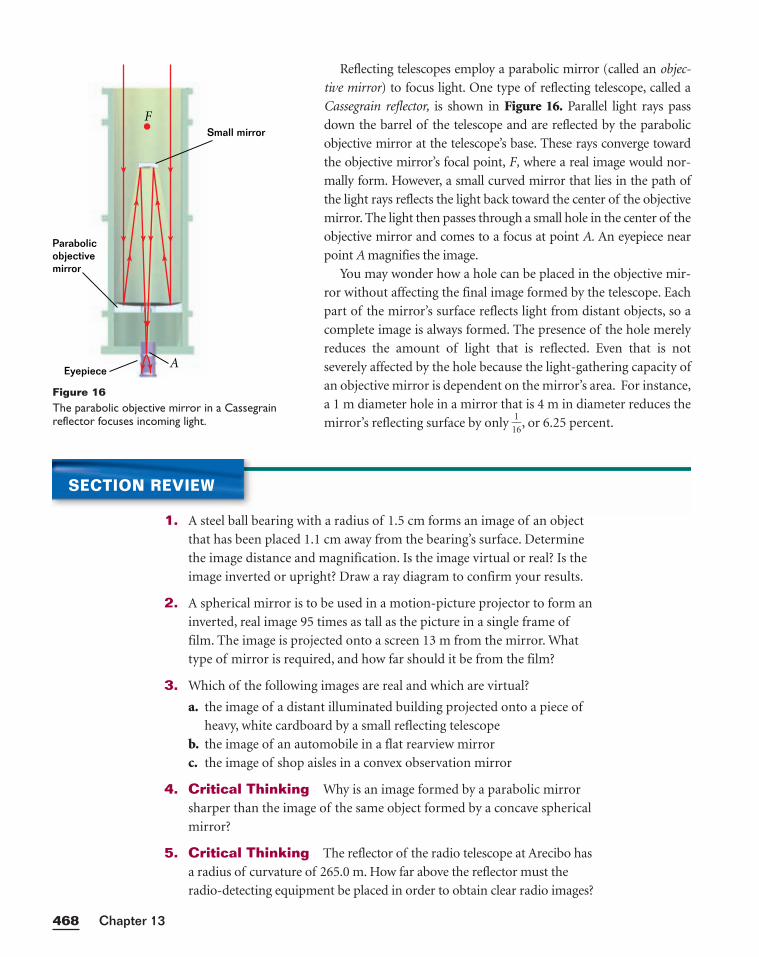
Reflecting telescopes employ a parabolic mirror (called an objec-
tive mirror) to focus light. One type of reflecting telescope, called a
Cassegrain reflector, is shown in Figure 16. Parallel light rays pass
down the barrel of the telescope and are reflected by the parabolic
objective mirror at the telescope’s base. These rays converge toward
the objective mirror’s focal point, F, where a real image would nor-
mally form. However, a small curved mirror that lies in the path of
the light rays reflects the light back toward the center of the objective
mirror. The light then passes through a small hole in the center of the
objective mirror and comes to a focus at point A. An eyepiece near
point A magnifies the image.
You may wonder how a hole can be placed in the objective mir-
ror without affecting the final image formed by the telescope. Each
part of the mirror’s surface reflects light from distant objects, so a
complete image is always formed. The presence of the hole merely
reduces the amount of light that is reflected. Even that is not
severely affected by the hole because the light-gathering capacity of
an objective mirror is dependent on the mirror’s area. For instance,
a 1 m diameter hole in a mirror that is 4 m in diameter reduces the
mirror’s reflecting surface by only 1
1
6, or 6.25 percent.
Chapter 13468
Small mirror
Parabolic objectivemirror
Eyepiece
F
A
Figure 16The parabolic objective mirror in a Cassegrainreflector focuses incoming light.
SECTION REVIEW
1. A steel ball bearing with a radius of 1.5 cm forms an image of an object
that has been placed 1.1 cm away from the bearing’s surface. Determine
the image distance and magnification. Is the image virtual or real? Is the
image inverted or upright? Draw a ray diagram to confirm your results.
2. A spherical mirror is to be used in a motion-picture projector to form an
inverted, real image 95 times as tall as the picture in a single frame of
film. The image is projected onto a screen 13 m from the mirror. What
type of mirror is required, and how far should it be from the film?
3. Which of the following images are real and which are virtual?
a. the image of a distant illuminated building projected onto a piece of
heavy, white cardboard by a small reflecting telescope
b. the image of an automobile in a flat rearview mirror
c. the image of shop aisles in a convex observation mirror
4. Critical Thinking Why is an image formed by a parabolic mirror
sharper than the image of the same object formed by a concave spherical
mirror?
5. Critical Thinking The reflector of the radio telescope at Arecibo has
a radius of curvature of 265.0 m. How far above the reflector must the
radio-detecting equipment be placed in order to obtain clear radio images?
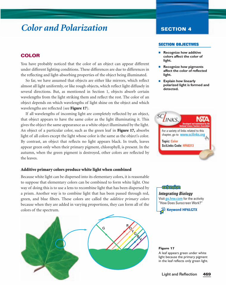
SECTION OBJECTIVES
■ Recognize how additive colors affect the color oflight.
■ Recognize how pigmentsaffect the color of reflectedlight.
■ Explain how linearlypolarized light is formed anddetected.
469Light and Reflection
Color and Polarization SECTION 4
COLOR
You have probably noticed that the color of an object can appear different
under different lighting conditions. These differences are due to differences in
the reflecting and light-absorbing properties of the object being illuminated.
So far, we have assumed that objects are either like mirrors, which reflect
almost all light uniformly, or like rough objects, which reflect light diffusely in
several directions. But, as mentioned in Section 1, objects absorb certain
wavelengths from the light striking them and reflect the rest. The color of an
object depends on which wavelengths of light shine on the object and which
wavelengths are reflected (see Figure 17).
If all wavelengths of incoming light are completely reflected by an object,
that object appears to have the same color as the light illuminating it. This
gives the object the same appearance as a white object illuminated by the light.
An object of a particular color, such as the green leaf in Figure 17, absorbs
light of all colors except the light whose color is the same as the object’s color.
By contrast, an object that reflects no light appears black. In truth, leaves
appear green only when their primary pigment, chlorophyll, is present. In the
autumn, when the green pigment is destroyed, other colors are reflected by
the leaves.
Additive primary colors produce white light when combined
Because white light can be dispersed into its elementary colors, it is reasonable
to suppose that elementary colors can be combined to form white light. One
way of doing this is to use a lens to recombine light that has been dispersed by
a prism. Another way is to combine light that has been passed through red,
green, and blue filters. These colors are called the additive primary colors
because when they are added in varying proportions, they can form all of the
colors of the spectrum.
G
GB
V
YO
R
Figure 17A leaf appears green under whitelight because the primary pigmentin the leaf reflects only green light.
Developed and maintained by theNational Science Teachers Association
For a variety of links related to thischapter, go to www.scilinks.org
Topic: ColorSciLinks Code: HF60313
Integrating BiologyVisit go.hrw.com for the activity“How Does Sunscreen Work?”
Keyword HF6LGTX
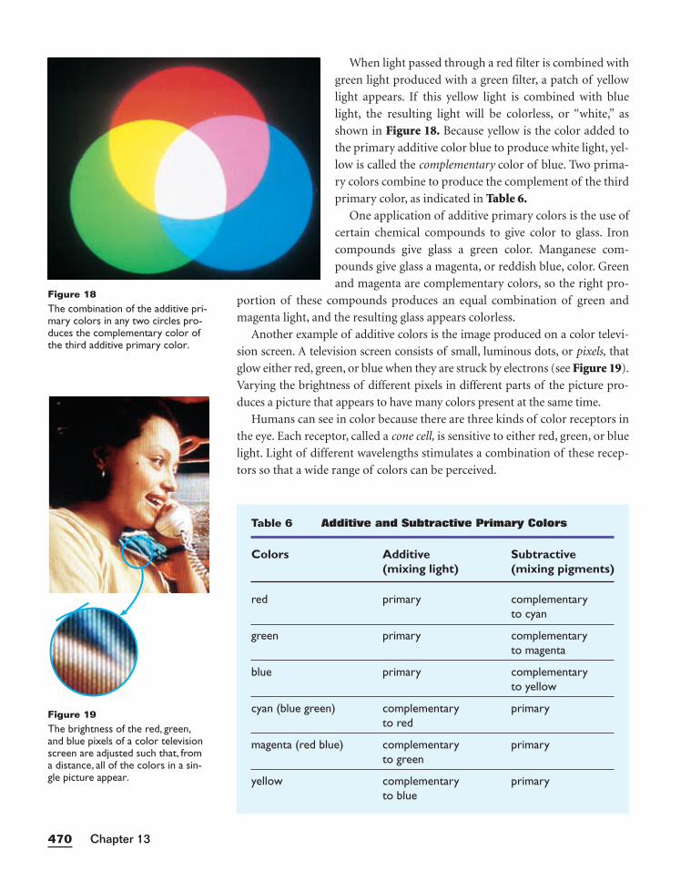
When light passed through a red filter is combined with
green light produced with a green filter, a patch of yellow
light appears. If this yellow light is combined with blue
light, the resulting light will be colorless, or “white,” as
shown in Figure 18. Because yellow is the color added to
the primary additive color blue to produce white light, yel-
low is called the complementary color of blue. Two prima-
ry colors combine to produce the complement of the third
primary color, as indicated in Table 6.One application of additive primary colors is the use of
certain chemical compounds to give color to glass. Iron
compounds give glass a green color. Manganese com-
pounds give glass a magenta, or reddish blue, color. Green
and magenta are complementary colors, so the right pro-
portion of these compounds produces an equal combination of green and
magenta light, and the resulting glass appears colorless.
Another example of additive colors is the image produced on a color televi-
sion screen. A television screen consists of small, luminous dots, or pixels, that
glow either red, green, or blue when they are struck by electrons (see Figure 19).
Varying the brightness of different pixels in different parts of the picture pro-
duces a picture that appears to have many colors present at the same time.
Humans can see in color because there are three kinds of color receptors in
the eye. Each receptor, called a cone cell, is sensitive to either red, green, or blue
light. Light of different wavelengths stimulates a combination of these recep-
tors so that a wide range of colors can be perceived.
Chapter 13470
Table 6 Additive and Subtractive Primary Colors
Colors Additive Subtractive(mixing light) (mixing pigments)
red primary complementaryto cyan
green primary complementaryto magenta
blue primary complementaryto yellow
cyan (blue green) complementary primaryto red
magenta (red blue) complementary primaryto green
yellow complementary primaryto blue
Figure 18The combination of the additive pri-mary colors in any two circles pro-duces the complementary color ofthe third additive primary color.
Figure 19The brightness of the red, green,and blue pixels of a color televisionscreen are adjusted such that, froma distance, all of the colors in a sin-gle picture appear.
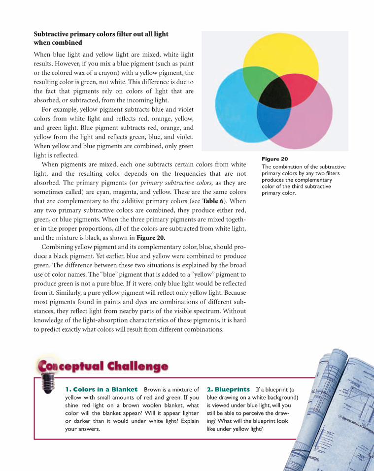
1. Colors in a Blanket Brown is a mixture ofyellow with small amounts of red and green. If youshine red light on a brown woolen blanket, whatcolor will the blanket appear? Will it appear lighteror darker than it would under white light? Explainyour answers.
2. Blueprints If a blueprint (ablue drawing on a white background)is viewed under blue light, will youstill be able to perceive the draw-ing? What will the blueprint looklike under yellow light?
Subtractive primary colors filter out all light when combined
When blue light and yellow light are mixed, white light
results. However, if you mix a blue pigment (such as paint
or the colored wax of a crayon) with a yellow pigment, the
resulting color is green, not white. This difference is due to
the fact that pigments rely on colors of light that are
absorbed, or subtracted, from the incoming light.
For example, yellow pigment subtracts blue and violet
colors from white light and reflects red, orange, yellow,
and green light. Blue pigment subtracts red, orange, and
yellow from the light and reflects green, blue, and violet.
When yellow and blue pigments are combined, only green
light is reflected.
When pigments are mixed, each one subtracts certain colors from white
light, and the resulting color depends on the frequencies that are not
absorbed. The primary pigments (or primary subtractive colors, as they are
sometimes called) are cyan, magenta, and yellow. These are the same colors
that are complementary to the additive primary colors (see Table 6). When
any two primary subtractive colors are combined, they produce either red,
green, or blue pigments. When the three primary pigments are mixed togeth-
er in the proper proportions, all of the colors are subtracted from white light,
and the mixture is black, as shown in Figure 20.Combining yellow pigment and its complementary color, blue, should pro-
duce a black pigment. Yet earlier, blue and yellow were combined to produce
green. The difference between these two situations is explained by the broad
use of color names. The “blue” pigment that is added to a “yellow” pigment to
produce green is not a pure blue. If it were, only blue light would be reflected
from it. Similarly, a pure yellow pigment will reflect only yellow light. Because
most pigments found in paints and dyes are combinations of different sub-
stances, they reflect light from nearby parts of the visible spectrum. Without
knowledge of the light-absorption characteristics of these pigments, it is hard
to predict exactly what colors will result from different combinations.
Figure 20The combination of the subtractiveprimary colors by any two filtersproduces the complementary color of the third subtractive primary color.
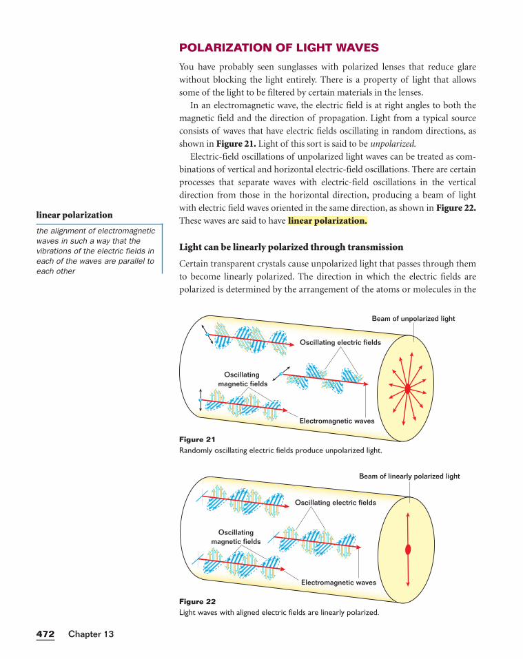
POLARIZATION OF LIGHT WAVES
You have probably seen sunglasses with polarized lenses that reduce glare
without blocking the light entirely. There is a property of light that allows
some of the light to be filtered by certain materials in the lenses.
In an electromagnetic wave, the electric field is at right angles to both the
magnetic field and the direction of propagation. Light from a typical source
consists of waves that have electric fields oscillating in random directions, as
shown in Figure 21. Light of this sort is said to be unpolarized.
Electric-field oscillations of unpolarized light waves can be treated as com-
binations of vertical and horizontal electric-field oscillations. There are certain
processes that separate waves with electric-field oscillations in the vertical
direction from those in the horizontal direction, producing a beam of light
with electric field waves oriented in the same direction, as shown in Figure 22.These waves are said to have
Light can be linearly polarized through transmission
Certain transparent crystals cause unpolarized light that passes through them
to become linearly polarized. The direction in which the electric fields are
polarized is determined by the arrangement of the atoms or molecules in the
linear polarization.
Chapter 13472
linear polarization
the alignment of electromagneticwaves in such a way that thevibrations of the electric fields ineach of the waves are parallel toeach other
Oscillating magnetic fields
Electromagnetic waves
Beam of unpolarized light
Oscillating electric fields
Figure 21Randomly oscillating electric fields produce unpolarized light.
Electromagnetic waves
Beam of linearly polarized light
Oscillating electric fields
Oscillating magnetic fields
Figure 22Light waves with aligned electric fields are linearly polarized.
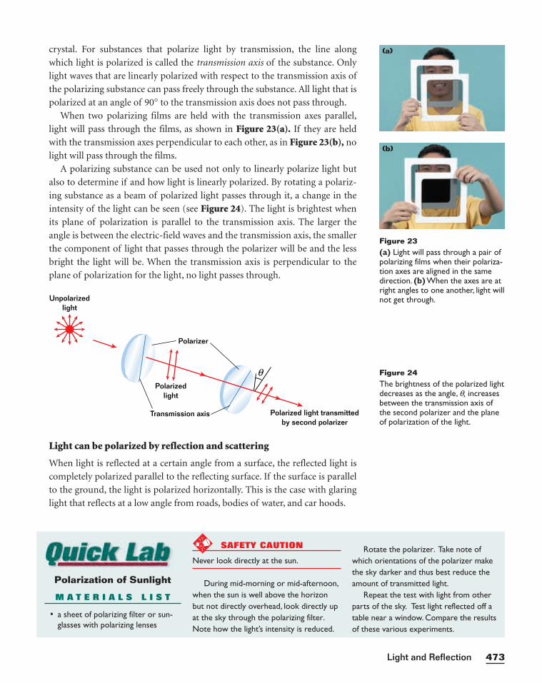
crystal. For substances that polarize light by transmission, the line along
which light is polarized is called the transmission axis of the substance. Only
light waves that are linearly polarized with respect to the transmission axis of
the polarizing substance can pass freely through the substance. All light that is
polarized at an angle of 90° to the transmission axis does not pass through.
When two polarizing films are held with the transmission axes parallel,
light will pass through the films, as shown in Figure 23(a). If they are held
with the transmission axes perpendicular to each other, as in Figure 23(b), no
light will pass through the films.
A polarizing substance can be used not only to linearly polarize light but
also to determine if and how light is linearly polarized. By rotating a polariz-
ing substance as a beam of polarized light passes through it, a change in the
intensity of the light can be seen (see Figure 24). The light is brightest when
its plane of polarization is parallel to the transmission axis. The larger the
angle is between the electric-field waves and the transmission axis, the smaller
the component of light that passes through the polarizer will be and the less
bright the light will be. When the transmission axis is perpendicular to the
plane of polarization for the light, no light passes through.
473Light and Reflection
Light can be polarized by reflection and scattering
When light is reflected at a certain angle from a surface, the reflected light is
completely polarized parallel to the reflecting surface. If the surface is parallel
to the ground, the light is polarized horizontally. This is the case with glaring
light that reflects at a low angle from roads, bodies of water, and car hoods.
Figure 23(a) Light will pass through a pair ofpolarizing films when their polariza-tion axes are aligned in the samedirection. (b) When the axes are atright angles to one another, light willnot get through.
Transmission axis
Polarizedlight
Polarizer
Polarized light transmittedby second polarizer
Unpolarizedlight
θ Figure 24The brightness of the polarized lightdecreases as the angle, q, increasesbetween the transmission axis ofthe second polarizer and the planeof polarization of the light.
Polarization of Sunlight
M A T E R I A L S L I S T
• a sheet of polarizing filter or sun-glasses with polarizing lenses
SAFETY CAUTION
Never look directly at the sun.
During mid-morning or mid-afternoon,when the sun is well above the horizonbut not directly overhead, look directly upat the sky through the polarizing filter.Note how the light’s intensity is reduced.
Rotate the polarizer. Take note ofwhich orientations of the polarizer makethe sky darker and thus best reduce theamount of transmitted light.
Repeat the test with light from otherparts of the sky. Test light reflected off atable near a window. Compare the resultsof these various experiments.
(a)
(b)
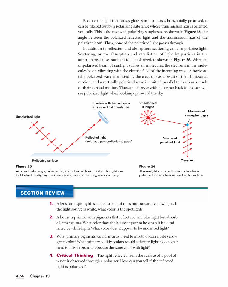
Because the light that causes glare is in most cases horizontally polarized, it
can be filtered out by a polarizing substance whose transmission axis is oriented
vertically. This is the case with polarizing sunglasses. As shown in Figure 25, the
angle between the polarized reflected light and the transmission axis of the
polarizer is 90°. Thus, none of the polarized light passes through.
In addition to reflection and absorption, scattering can also polarize light.
Scattering, or the absorption and reradiation of light by particles in the
atmosphere, causes sunlight to be polarized, as shown in Figure 26. When an
unpolarized beam of sunlight strikes air molecules, the electrons in the mole-
cules begin vibrating with the electric field of the incoming wave. A horizon-
tally polarized wave is emitted by the electrons as a result of their horizontal
motion, and a vertically polarized wave is emitted parallel to Earth as a result
of their vertical motion. Thus, an observer with his or her back to the sun will
see polarized light when looking up toward the sky.
Chapter 13474
Unpolarizedsunlight
Scatteredpolarized light
Molecule ofatmospheric gas
Observer
Figure 26The sunlight scattered by air molecules ispolarized for an observer on Earth’s surface.
Unpolarized light
Reflecting surface
Reflected light (polarized perpendicular to page)
Polarizer with transmissionaxis in vertical orientation
Figure 25At a particular angle, reflected light is polarized horizontally. This light can be blocked by aligning the transmission axes of the sunglasses vertically.
SECTION REVIEW
1. A lens for a spotlight is coated so that it does not transmit yellow light. If
the light source is white, what color is the spotlight?
2. A house is painted with pigments that reflect red and blue light but absorb
all other colors. What color does the house appear to be when it is illumi-
nated by white light? What color does it appear to be under red light?
3. What primary pigments would an artist need to mix to obtain a pale yellow
green color? What primary additive colors would a theater-lighting designer
need to mix in order to produce the same color with light?
4. Critical Thinking The light reflected from the surface of a pool of
water is observed through a polarizer. How can you tell if the reflected
light is polarized?
KEY IDEAS
Section 1 Characteristics of Light• Light is electromagnetic radiation that consists of oscillating electric and
magnetic fields with different wavelengths.
• The frequency times the wavelength of electromagnetic radiation is equal
to c, the speed of light.
• The brightness of light is inversely proportional to the square of the
distance from the light source.
Section 2 Flat Mirrors• Light obeys the law of reflection, which states that the incident and reflect-
ed angles of light are equal.
• Flat mirrors form virtual images that are the same distance from the
mirror’s surface as the object is.
Section 3 Curved Mirrors• The mirror equation relates object distance, image distance, and focal
length of a spherical mirror.
• The magnification equation relates image height or distance to object height
or distance, respectively.
Section 4 Color and Polarization• Light of different colors can be produced by adding light consisting of the
primary additive colors (red, green, and blue).
• Pigments can be produced by combining subtractive colors (magenta,
yellow, and cyan).
• Light can be linearly polarized by transmission, reflection, or scattering.
HighlightsCHAPTER 13
475Light and Reflection
Variable Symbols
Quantities Units
p object distance m meters
q image distance m meters
R radius of curvature m meters
f focal length m meters
M magnification (unitless)
KEY TERMS
electromagnetic wave (p. 446)
reflection (p. 451)
angle of incidence (p. 452)
angle of reflection (p. 452)
virtual image (p. 453)
concave spherical mirror (p.455)
real image (p. 456)
convex spherical mirror (p.463)
linear polarization (p. 472)
Diagram Symbols
Light rays (real)
Light rays (apparent)
Normal lines
Flat mirror
Concavemirror
Convexmirror
PROBLEM SOLVING
See Appendix D: Equations for a summary of the equationsintroduced in this chapter. Ifyou need more problem-solvingpractice, see Appendix I: Additional Problems.
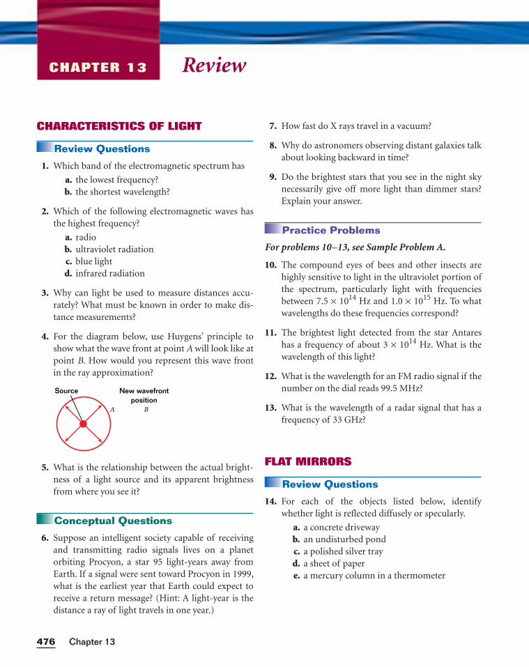
ReviewCHAPTER 13
CHARACTERISTICS OF LIGHT
Review Questions
1. Which band of the electromagnetic spectrum has
a. the lowest frequency?b. the shortest wavelength?
2. Which of the following electromagnetic waves hasthe highest frequency?
a. radiob. ultraviolet radiationc. blue lightd. infrared radiation
3. Why can light be used to measure distances accu-rately? What must be known in order to make dis-tance measurements?
4. For the diagram below, use Huygens’ principle toshow what the wave front at point A will look like atpoint B. How would you represent this wave frontin the ray approximation?
5. What is the relationship between the actual bright-ness of a light source and its apparent brightnessfrom where you see it?
Conceptual Questions
6. Suppose an intelligent society capable of receivingand transmitting radio signals lives on a planetorbiting Procyon, a star 95 light-years away fromEarth. If a signal were sent toward Procyon in 1999,what is the earliest year that Earth could expect toreceive a return message? (Hint: A light-year is thedistance a ray of light travels in one year.)
A B
New wavefrontposition
Source
7. How fast do X rays travel in a vacuum?
8. Why do astronomers observing distant galaxies talkabout looking backward in time?
9. Do the brightest stars that you see in the night skynecessarily give off more light than dimmer stars?Explain your answer.
Practice Problems
For problems 10–13, see Sample Problem A.
10. The compound eyes of bees and other insects arehighly sensitive to light in the ultraviolet portion ofthe spectrum, particularly light with frequenciesbetween 7.5 × 10¹⁴ Hz and 1.0 × 10¹⁵ Hz. To whatwavelengths do these frequencies correspond?
11. The brightest light detected from the star Antareshas a frequency of about 3 × 10¹⁴ Hz. What is thewavelength of this light?
12. What is the wavelength for an FM radio signal if thenumber on the dial reads 99.5 MHz?
13. What is the wavelength of a radar signal that has afrequency of 33 GHz?
FLAT MIRRORS
Review Questions
14. For each of the objects listed below, identifywhether light is reflected diffusely or specularly.
a. a concrete drivewayb. an undisturbed pondc. a polished silver trayd. a sheet of papere. a mercury column in a thermometer
Chapter 13476
15. If you are stranded on an island, where would youalign a mirror to use sunlight to signal a searchingaircraft?
16. If you are standing 2 m in front of a flat mirror, howfar behind the mirror is your image? What is themagnification of the image?
Conceptual Questions
17. When you shine a flashlight across a room, you seethe beam of light on the wall. Why do you not seethe light in the air?
18. How can an object be a specular reflector for someelectromagnetic waves yet be diffuse for others?
19. A flat mirror that is 0.85 m tall is attached to a wallso that its upper edge is 1.7 m above the floor. Usethe law of reflection and a ray diagram to determineif this mirror will show a person who is 1.7 m tallhis or her complete reflection.
20. Two flat mirrors make anangle of 90.0° with eachother, as diagrammed atright. An incoming raymakes an angle of 35° withthe normal of mirror A.Use the law of reflection to determine the angle ofreflection from mirror B. What is unusual about theincoming and reflected rays of light for this arrange-ment of mirrors?
21. If you walk 1.2 m/s toward a flat mirror, how fastdoes your image move with respect to the mirror?In what direction does your image move withrespect to you?
22. Why do the images produced by two opposing flatmirrors appear to be progressively smaller?
CURVED MIRRORS
Review Questions
23. Which type of mirror should be used to projectmovie images on a large screen?
24. If an object is placed outside the focal length of aconcave mirror, which type of image will be formed?Will it appear in front of or behind the mirror?
25. Can you use a convex mirror to burn a hole in paperby focusing light rays from the sun at the mirror’sfocal point?
26. A convex mirror forms an image from a real object.Can the image ever be larger than the object?
27. Why are parabolic mirrors preferred over sphericalconcave mirrors for use in reflecting telescopes?
Conceptual Questions
28. Where does a ray of light that is parallel to the prin-cipal axis of a concave mirror go after it is reflectedat the mirror’s surface?
29. What happens to the real image produced by a con-cave mirror if you move the original object to thelocation of the image?
30. Consider a concave spherical mirror and a realobject. Is the image always inverted? Is the imagealways real? Give conditions for your answers.
31. Explain why enlarged images seem dimmer thanthe original objects.
32. What test could you perform to determine if animage is real or virtual?
33. You’ve been given a concave mirror that may or maynot be parabolic. What test could you perform todetermine whether it is parabolic?
Practice Problems
For problems 34–35, see Sample Problem B.
34. A concave shaving mirror has a radius of curvatureof 25.0 cm. For each of the following cases, find themagnification, and determine whether the imageformed is real or virtual and upright or inverted.
a. an upright pencil placed 45.0 cm from themirror
b. an upright pencil placed 25.0 cm from themirror
c. an upright pencil placed 5.00 cm from themirror
477Light and Reflection
= 35°θ
Mirror A
Mir
ror
B
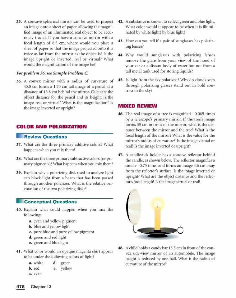
35. A concave spherical mirror can be used to projectan image onto a sheet of paper, allowing the magni-fied image of an illuminated real object to be accu-rately traced. If you have a concave mirror with afocal length of 8.5 cm, where would you place asheet of paper so that the image projected onto it istwice as far from the mirror as the object is? Is theimage upright or inverted, real or virtual? Whatwould the magnification of the image be?
For problem 36, see Sample Problem C.
36. A convex mirror with a radius of curvature of45.0 cm forms a 1.70 cm tall image of a pencil at adistance of 15.8 cm behind the mirror. Calculate theobject distance for the pencil and its height. Is theimage real or virtual? What is the magnification? Isthe image inverted or upright?
COLOR AND POLARIZATION
Review Questions
37. What are the three primary additive colors? Whathappens when you mix them?
38. What are the three primary subtractive colors (or pri-mary pigments)? What happens when you mix them?
39. Explain why a polarizing disk used to analyze lightcan block light from a beam that has been passedthrough another polarizer. What is the relative ori-entation of the two polarizing disks?
Conceptual Questions
40. Explain what could happen when you mix the following:
a. cyan and yellow pigmentb. blue and yellow lightc. pure blue and pure yellow pigmentd. green and red lighte. green and blue light
41. What color would an opaque magenta shirt appearto be under the following colors of light?
a. white d. greenb. red e. yellowc. cyan
42. A substance is known to reflect green and blue light.What color would it appear to be when it is illumi-nated by white light? by blue light?
43. How can you tell if a pair of sunglasses has polariz-ing lenses?
44. Why would sunglasses with polarizing lensesremove the glare from your view of the hood ofyour car or a distant body of water but not from atall metal tank used for storing liquids?
45. Is light from the sky polarized? Why do clouds seenthrough polarizing glasses stand out in bold con-trast to the sky?
MIXED REVIEW
46. The real image of a tree is magnified −0.085 timesby a telescope’s primary mirror. If the tree’s imageforms 35 cm in front of the mirror, what is the dis-tance between the mirror and the tree? What is thefocal length of the mirror? What is the value for themirror’s radius of curvature? Is the image virtual orreal? Is the image inverted or upright?
47. A candlestick holder has a concave reflector behindthe candle, as shown below. The reflector magnifies acandle –0.75 times and forms an image 4.6 cm awayfrom the reflector’s surface. Is the image inverted orupright? What are the object distance and the reflec-tor’s focal length? Is the image virtual or real?
48. A child holds a candy bar 15.5 cm in front of the con-vex side-view mirror of an automobile. The imageheight is reduced by one-half. What is the radius ofcurvature of the mirror?
Chapter 13478
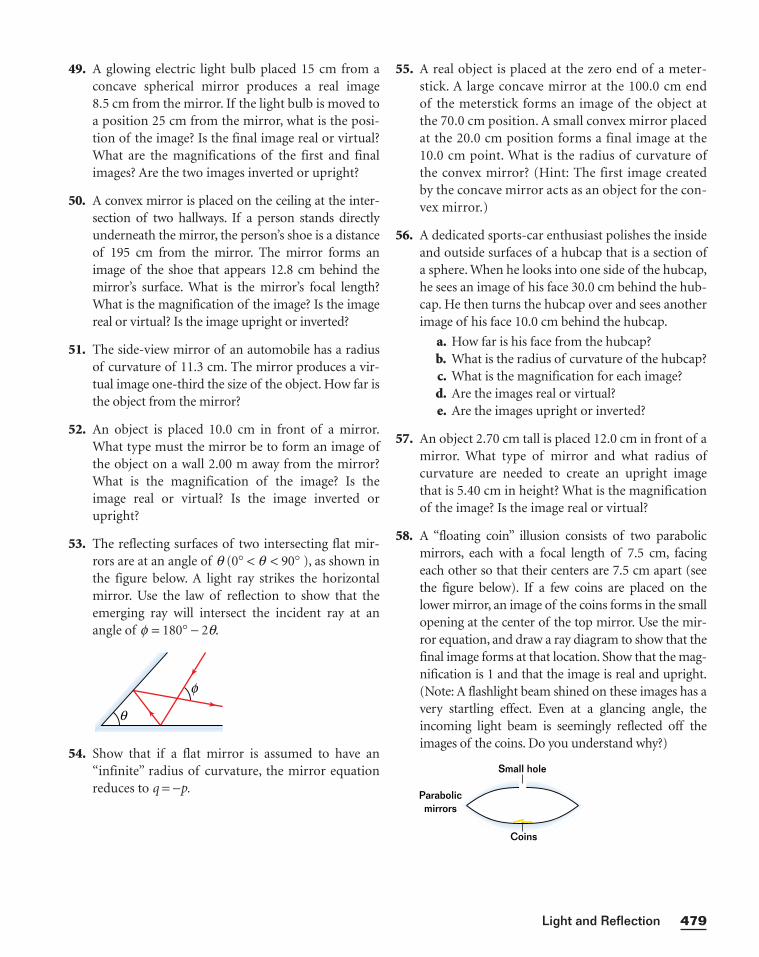
49. A glowing electric light bulb placed 15 cm from aconcave spherical mirror produces a real image 8.5 cm from the mirror. If the light bulb is moved toa position 25 cm from the mirror, what is the posi-tion of the image? Is the final image real or virtual?What are the magnifications of the first and finalimages? Are the two images inverted or upright?
50. A convex mirror is placed on the ceiling at the inter-section of two hallways. If a person stands directlyunderneath the mirror, the person’s shoe is a distanceof 195 cm from the mirror. The mirror forms animage of the shoe that appears 12.8 cm behind themirror’s surface. What is the mirror’s focal length?What is the magnification of the image? Is the imagereal or virtual? Is the image upright or inverted?
51. The side-view mirror of an automobile has a radiusof curvature of 11.3 cm. The mirror produces a vir-tual image one-third the size of the object. How far isthe object from the mirror?
52. An object is placed 10.0 cm in front of a mirror.What type must the mirror be to form an image ofthe object on a wall 2.00 m away from the mirror?What is the magnification of the image? Is theimage real or virtual? Is the image inverted orupright?
53. The reflecting surfaces of two intersecting flat mir-rors are at an angle of q (0° < q < 90° ), as shown inthe figure below. A light ray strikes the horizontalmirror. Use the law of reflection to show that theemerging ray will intersect the incident ray at anangle of f = 180° − 2q.
54. Show that if a flat mirror is assumed to have an“infinite” radius of curvature, the mirror equationreduces to q = −p.
θ
f
55. A real object is placed at the zero end of a meter-stick. A large concave mirror at the 100.0 cm endof the meterstick forms an image of the object atthe 70.0 cm position. A small convex mirror placedat the 20.0 cm position forms a final image at the10.0 cm point. What is the radius of curvature ofthe convex mirror? (Hint: The first image createdby the concave mirror acts as an object for the con-vex mirror.)
56. A dedicated sports-car enthusiast polishes the insideand outside surfaces of a hubcap that is a section ofa sphere. When he looks into one side of the hubcap,he sees an image of his face 30.0 cm behind the hub-cap. He then turns the hubcap over and sees anotherimage of his face 10.0 cm behind the hubcap.
a. How far is his face from the hubcap?b. What is the radius of curvature of the hubcap?c. What is the magnification for each image?d. Are the images real or virtual?e. Are the images upright or inverted?
57. An object 2.70 cm tall is placed 12.0 cm in front of amirror. What type of mirror and what radius ofcurvature are needed to create an upright imagethat is 5.40 cm in height? What is the magnificationof the image? Is the image real or virtual?
58. A “floating coin” illusion consists of two parabolicmirrors, each with a focal length of 7.5 cm, facingeach other so that their centers are 7.5 cm apart (seethe figure below). If a few coins are placed on thelower mirror, an image of the coins forms in the smallopening at the center of the top mirror. Use the mir-ror equation, and draw a ray diagram to show that thefinal image forms at that location. Show that the mag-nification is 1 and that the image is real and upright.(Note: A flashlight beam shined on these images has avery startling effect. Even at a glancing angle, theincoming light beam is seemingly reflected off theimages of the coins. Do you understand why?)
Parabolicmirrors
Small hole
Coins
479Light and Reflection
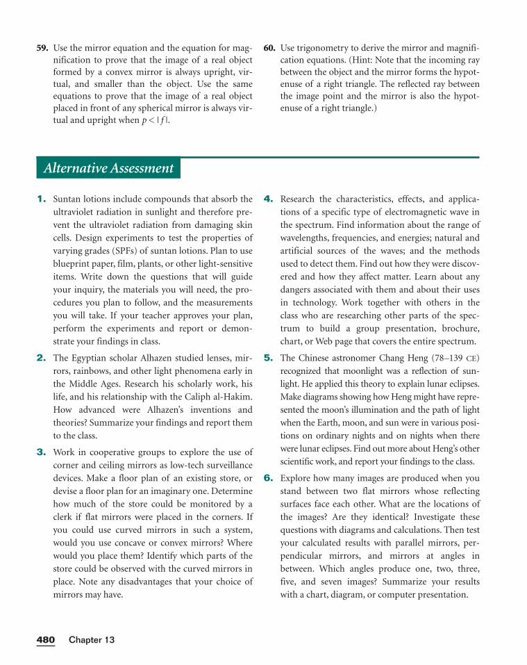
59. Use the mirror equation and the equation for mag-nification to prove that the image of a real objectformed by a convex mirror is always upright, vir-tual, and smaller than the object. Use the sameequations to prove that the image of a real objectplaced in front of any spherical mirror is always vir-tual and upright when p < | f |.
60. Use trigonometry to derive the mirror and magnifi-cation equations. (Hint: Note that the incoming raybetween the object and the mirror forms the hypot-enuse of a right triangle. The reflected ray betweenthe image point and the mirror is also the hypot-enuse of a right triangle.)
Chapter 13480
1. Suntan lotions include compounds that absorb the
ultraviolet radiation in sunlight and therefore pre-
vent the ultraviolet radiation from damaging skin
cells. Design experiments to test the properties of
varying grades (SPFs) of suntan lotions. Plan to use
blueprint paper, film, plants, or other light-sensitive
items. Write down the questions that will guide
your inquiry, the materials you will need, the pro-
cedures you plan to follow, and the measurements
you will take. If your teacher approves your plan,
perform the experiments and report or demon-
strate your findings in class.
2. The Egyptian scholar Alhazen studied lenses, mir-
rors, rainbows, and other light phenomena early in
the Middle Ages. Research his scholarly work, his
life, and his relationship with the Caliph al-Hakim.
How advanced were Alhazen’s inventions and
theories? Summarize your findings and report them
to the class.
3. Work in cooperative groups to explore the use of
corner and ceiling mirrors as low-tech surveillance
devices. Make a floor plan of an existing store, or
devise a floor plan for an imaginary one. Determine
how much of the store could be monitored by a
clerk if flat mirrors were placed in the corners. If
you could use curved mirrors in such a system,
would you use concave or convex mirrors? Where
would you place them? Identify which parts of the
store could be observed with the curved mirrors in
place. Note any disadvantages that your choice of
mirrors may have.
4. Research the characteristics, effects, and applica-
tions of a specific type of electromagnetic wave in
the spectrum. Find information about the range of
wavelengths, frequencies, and energies; natural and
artificial sources of the waves; and the methods
used to detect them. Find out how they were discov-
ered and how they affect matter. Learn about any
dangers associated with them and about their uses
in technology. Work together with others in the
class who are researching other parts of the spec-
trum to build a group presentation, brochure,
chart, or Web page that covers the entire spectrum.
5. The Chinese astronomer Chang Heng (78–139 CE)
recognized that moonlight was a reflection of sun-
light. He applied this theory to explain lunar eclipses.
Make diagrams showing how Heng might have repre-
sented the moon’s illumination and the path of light
when the Earth, moon, and sun were in various posi-
tions on ordinary nights and on nights when there
were lunar eclipses. Find out more about Heng’s other
scientific work, and report your findings to the class.
6. Explore how many images are produced when you
stand between two flat mirrors whose reflecting
surfaces face each other. What are the locations of
the images? Are they identical? Investigate these
questions with diagrams and calculations. Then test
your calculated results with parallel mirrors, per-
pendicular mirrors, and mirrors at angles in
between. Which angles produce one, two, three,
five, and seven images? Summarize your results
with a chart, diagram, or computer presentation.
Alternative Assessment
481Light and Reflection
larger than the object itself. Negative magnification
values indicate that an image is real and inverted,
while positive magnification values indicate that an
image is virtual and upright.
In this graphing calculator activity, the calculator
will produce a table of image distance and magnifi-
cation for various object distances for a mirror with
a known focal length. You will use this table to
determine the characteristics of the images pro-
duced by a variety of mirrors and object distances.
Visit go.hrw.com and enter the keyword
HF6LGTX to find this graphing calculator activity.
Refer to Appendix B for instructions on download-
ing the program for this activity.
MirrorsMirrors produce many types of images: virtual or
real, enlarged or reduced, and upright or inverted.
The mirror equation and the magnification equa-
tion can help sort things out. The mirror equation
relates the object distance (p), image distance (q),
and focal length (f ) to one another.
⎯p
1⎯ + ⎯
1
q⎯ = ⎯
1
f⎯
Image size can be determined from the magnifi-
cation equation.
M = − ⎯p
q⎯
Magnification values that are greater than 1 or
less than –1 indicate that the image of an object is
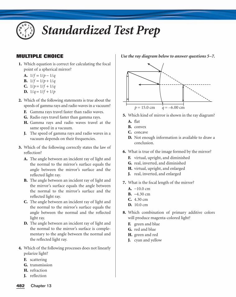
Standardized Test Prep
MULTIPLE CHOICE
1. Which equation is correct for calculating the focalpoint of a spherical mirror?
A. 1/f = 1/p − 1/qB. 1/f = 1/p + 1/qC. 1/p = 1/f + 1/qD. 1/q = 1/f + 1/p
2. Which of the following statements is true about thespeeds of gamma rays and radio waves in a vacuum?
F. Gamma rays travel faster than radio waves.G. Radio rays travel faster than gamma rays.H. Gamma rays and radio waves travel at the
same speed in a vacuum.J. The speed of gamma rays and radio waves in a
vacuum depends on their frequencies.
3. Which of the following correctly states the law ofreflection?
A. The angle between an incident ray of light andthe normal to the mirror’s surface equals theangle between the mirror’s surface and thereflected light ray.
B. The angle between an incident ray of light andthe mirror’s surface equals the angle betweenthe normal to the mirror’s surface and thereflected light ray.
C. The angle between an incident ray of light andthe normal to the mirror’s surface equals theangle between the normal and the reflectedlight ray.
D. The angle between an incident ray of light andthe normal to the mirror’s surface is comple-mentary to the angle between the normal andthe reflected light ray.
4. Which of the following processes does not linearlypolarize light?
F. scatteringG. transmissionH. refractionJ. reflection
Use the ray diagram below to answer questions 5–7.
5. Which kind of mirror is shown in the ray diagram?
A. flatB. convexC. concaveD. Not enough information is available to draw a
conclusion.
6. What is true of the image formed by the mirror?
F. virtual, upright, and diminishedG. real, inverted, and diminishedH. virtual, upright, and enlargedJ. real, inverted, and enlarged
7. What is the focal length of the mirror?
A. −10.0 cmB. −4.30 cmC. 4.30 cmD. 10.0 cm
8. Which combination of primary additive colorswill produce magenta-colored light?
F. green and blueG. red and blueH. green and redJ. cyan and yellow
p = 15.0 cm q = –6.00 cm
Chapter 13482
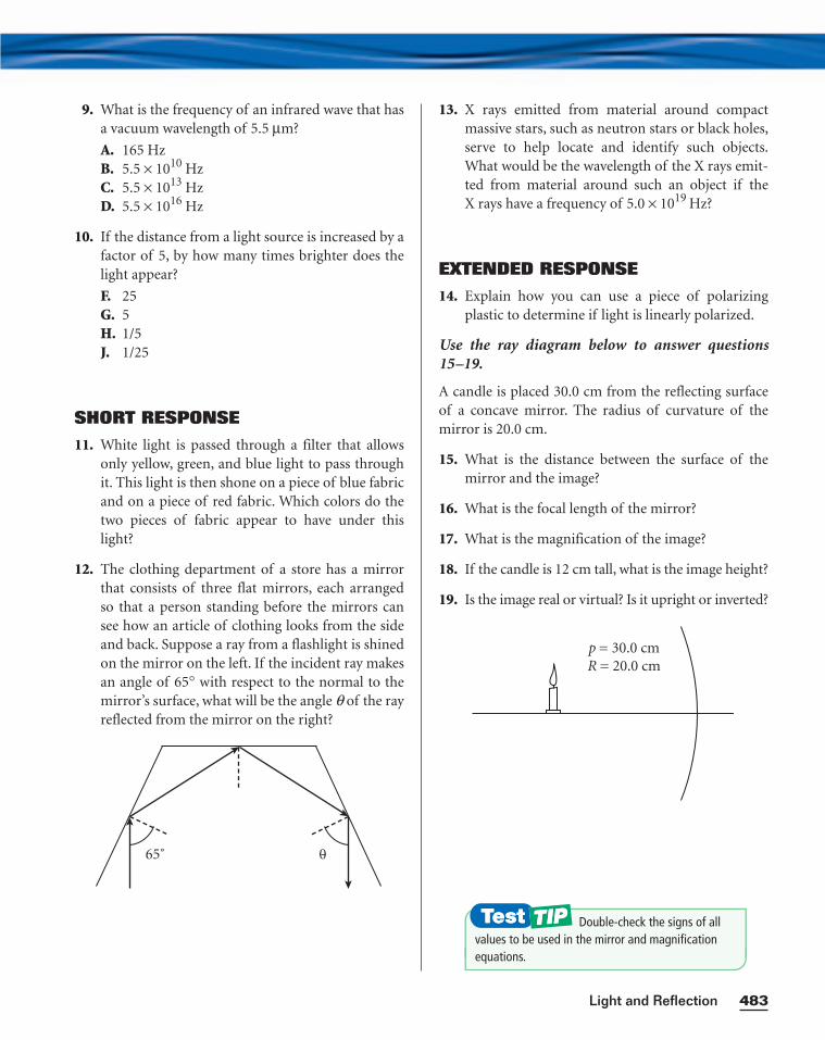
9. What is the frequency of an infrared wave that hasa vacuum wavelength of 5.5 µm?
A. 165 HzB. 5.5 × 10¹⁰ HzC. 5.5 × 10¹³ HzD. 5.5 × 10¹⁶ Hz
10. If the distance from a light source is increased by afactor of 5, by how many times brighter does thelight appear?
F. 25G. 5H. 1/5J. 1/25
SHORT RESPONSE
11. White light is passed through a filter that allowsonly yellow, green, and blue light to pass throughit. This light is then shone on a piece of blue fabricand on a piece of red fabric. Which colors do thetwo pieces of fabric appear to have under thislight?
12. The clothing department of a store has a mirrorthat consists of three flat mirrors, each arrangedso that a person standing before the mirrors cansee how an article of clothing looks from the sideand back. Suppose a ray from a flashlight is shinedon the mirror on the left. If the incident ray makesan angle of 65° with respect to the normal to themirror’s surface, what will be the angle q of the rayreflected from the mirror on the right?
65˚ 0
13. X rays emitted from material around compactmassive stars, such as neutron stars or black holes,serve to help locate and identify such objects.What would be the wavelength of the X rays emit-ted from material around such an object if theX rays have a frequency of 5.0 × 10¹⁹ Hz?
EXTENDED RESPONSE
14. Explain how you can use a piece of polarizingplastic to determine if light is linearly polarized.
Use the ray diagram below to answer questions15–19.
A candle is placed 30.0 cm from the reflecting surfaceof a concave mirror. The radius of curvature of themirror is 20.0 cm.
15. What is the distance between the surface of themirror and the image?
16. What is the focal length of the mirror?
17. What is the magnification of the image?
18. If the candle is 12 cm tall, what is the image height?
19. Is the image real or virtual? Is it upright or inverted?
p = 30.0 cmR = 20.0 cm
483Light and Reflection
Double-check the signs of all values to be used in the mirror and magnificationequations.
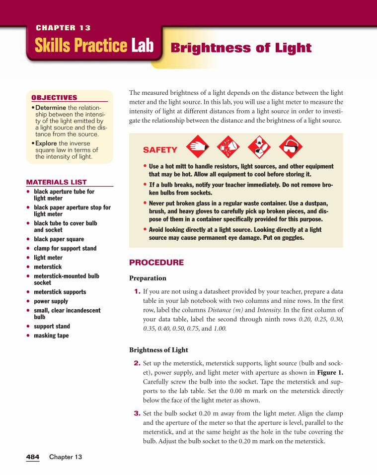
Chapter 13484
PROCEDURE
Preparation
1. If you are not using a datasheet provided by your teacher, prepare a data
table in your lab notebook with two columns and nine rows. In the first
row, label the columns Distance (m) and Intensity. In the first column of
your data table, label the second through ninth rows 0.20, 0.25, 0.30,
0.35, 0.40, 0.50, 0.75, and 1.00.
Brightness of Light
2. Set up the meterstick, meterstick supports, light source (bulb and sock-
et), power supply, and light meter with aperture as shown in Figure 1.Carefully screw the bulb into the socket. Tape the meterstick and sup-
ports to the lab table. Set the 0.00 m mark on the meterstick directly
below the face of the light meter as shown.
3. Set the bulb socket 0.20 m away from the light meter. Align the clamp
and the aperture of the meter so that the aperture is level, parallel to the
meterstick, and at the same height as the hole in the tube covering the
bulb. Adjust the bulb socket to the 0.20 m mark on the meterstick.
The measured brightness of a light depends on the distance between the light
meter and the light source. In this lab, you will use a light meter to measure the
intensity of light at different distances from a light source in order to investi-
gate the relationship between the distance and the brightness of a light source.
OBJECTIVES
•Determine the relation-ship between the intensi-ty of the light emitted bya light source and the dis-tance from the source.
•Explore the inversesquare law in terms ofthe intensity of light.
MATERIALS LIST• black aperture tube for
light meter• black paper aperture stop for
light meter• black tube to cover bulb
and socket• black paper square• clamp for support stand• light meter• meterstick• meterstick-mounted bulb
socket• meterstick supports• power supply• small, clear incandescent
bulb• support stand• masking tape
Skills Practice LabCHAPTER 13
Brightness of Light
SAFETY
• Use a hot mitt to handle resistors, light sources, and other equipmentthat may be hot. Allow all equipment to cool before storing it.
• If a bulb breaks, notify your teacher immediately. Do not remove bro-ken bulbs from sockets.
• Never put broken glass in a regular waste container. Use a dustpan,brush, and heavy gloves to carefully pick up broken pieces, and dis-pose of them in a container specifically provided for this purpose.
• Avoid looking directly at a light source. Looking directly at a lightsource may cause permanent eye damage. Put on goggles.
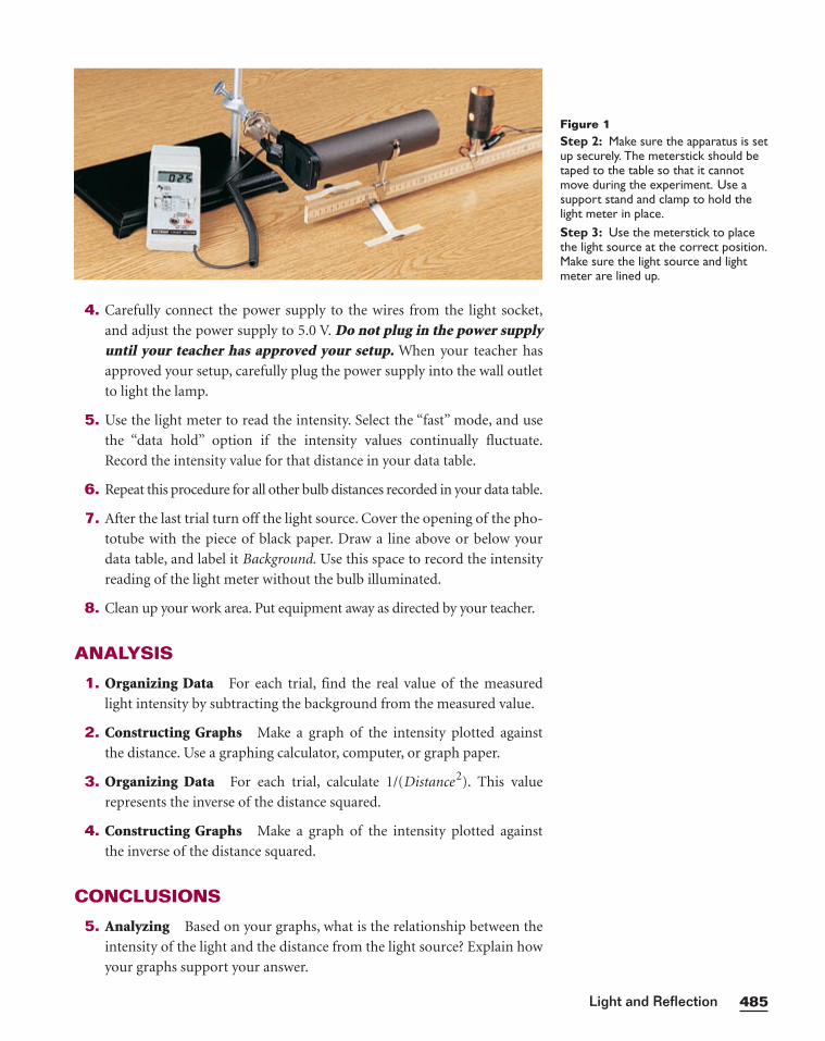
485Light and Reflection
4. Carefully connect the power supply to the wires from the light socket,
and adjust the power supply to 5.0 V. Do not plug in the power supplyuntil your teacher has approved your setup. When your teacher has
approved your setup, carefully plug the power supply into the wall outlet
to light the lamp.
5. Use the light meter to read the intensity. Select the “fast” mode, and use
the “data hold” option if the intensity values continually fluctuate.
Record the intensity value for that distance in your data table.
6. Repeat this procedure for all other bulb distances recorded in your data table.
7. After the last trial turn off the light source. Cover the opening of the pho-
totube with the piece of black paper. Draw a line above or below your
data table, and label it Background. Use this space to record the intensity
reading of the light meter without the bulb illuminated.
8. Clean up your work area. Put equipment away as directed by your teacher.
ANALYSIS
1. Organizing Data For each trial, find the real value of the measured
light intensity by subtracting the background from the measured value.
2. Constructing Graphs Make a graph of the intensity plotted against
the distance. Use a graphing calculator, computer, or graph paper.
3. Organizing Data For each trial, calculate 1/(Distance2). This value
represents the inverse of the distance squared.
4. Constructing Graphs Make a graph of the intensity plotted against
the inverse of the distance squared.
CONCLUSIONS
5. Analyzing Based on your graphs, what is the relationship between the
intensity of the light and the distance from the light source? Explain how
your graphs support your answer.
Figure 1Step 2: Make sure the apparatus is setup securely. The meterstick should betaped to the table so that it cannotmove during the experiment. Use asupport stand and clamp to hold thelight meter in place.Step 3: Use the meterstick to placethe light source at the correct position.Make sure the light source and lightmeter are lined up.

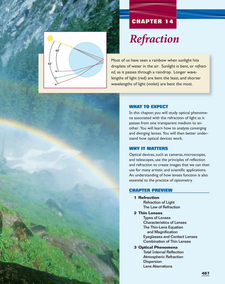
487
Most of us have seen a rainbow when sunlight hitsdroplets of water in the air. Sunlight is bent, or refract-ed, as it passes through a raindrop. Longer wave-lengths of light (red) are bent the least, and shorterwavelengths of light (violet) are bent the most.
CHAPTER 14
42˚
40˚
Refraction
WHAT TO EXPECTIn this chapter, you will study optical phenome-na associated with the refraction of light as itpasses from one transparent medium to an-other. You will learn how to analyze convergingand diverging lenses. You will then better under-stand how optical devices work.
WHY IT MATTERSOptical devices, such as cameras, microscopes,and telescopes, use the principles of reflectionand refraction to create images that we can thenuse for many artistic and scientific applications.An understanding of how lenses function is alsoessential to the practice of optometry.
CHAPTER PREVIEW
1 RefractionRefraction of LightThe Law of Refraction
2 Thin LensesTypes of LensesCharacteristics of LensesThe Thin-Lens Equation
and MagnificationEyeglasses and Contact LensesCombination of Thin Lenses
3 Optical PhenomenaTotal Internal ReflectionAtmospheric RefractionDispersionLens Aberrations
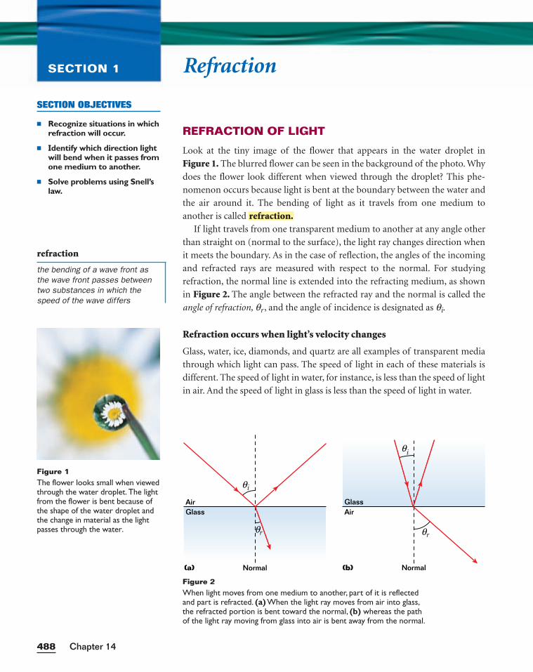
RefractionSECTION 1
REFRACTION OF LIGHT
Look at the tiny image of the flower that appears in the water droplet in
Figure 1. The blurred flower can be seen in the background of the photo. Why
does the flower look different when viewed through the droplet? This phe-
nomenon occurs because light is bent at the boundary between the water and
the air around it. The bending of light as it travels from one medium to
another is called
If light travels from one transparent medium to another at any angle other
than straight on (normal to the surface), the light ray changes direction when
it meets the boundary. As in the case of reflection, the angles of the incoming
and refracted rays are measured with respect to the normal. For studying
refraction, the normal line is extended into the refracting medium, as shown
in Figure 2. The angle between the refracted ray and the normal is called the
angle of refraction, qr , and the angle of incidence is designated as qi.
Refraction occurs when light’s velocity changes
Glass, water, ice, diamonds, and quartz are all examples of transparent media
through which light can pass. The speed of light in each of these materials is
different. The speed of light in water, for instance, is less than the speed of light
in air. And the speed of light in glass is less than the speed of light in water.
refraction.
Chapter 14488
SECTION OBJECTIVES
■ Recognize situations in whichrefraction will occur.
■ Identify which direction lightwill bend when it passes fromone medium to another.
■ Solve problems using Snell’slaw.
Figure 1The flower looks small when viewedthrough the water droplet. The lightfrom the flower is bent because ofthe shape of the water droplet andthe change in material as the lightpasses through the water.
refraction
the bending of a wave front asthe wave front passes betweentwo substances in which thespeed of the wave differs
Air
(a) Normal
Glass
θi
θr
Normal
AirGlass
θi
θr
(b)
Figure 2When light moves from one medium to another, part of it is reflectedand part is refracted. (a) When the light ray moves from air into glass,the refracted portion is bent toward the normal, (b) whereas the pathof the light ray moving from glass into air is bent away from the normal.
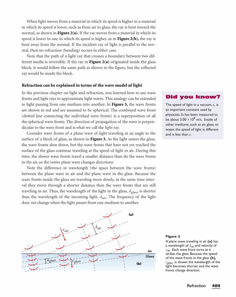
When light moves from a material in which its speed is higher to a material
in which its speed is lower, such as from air to glass, the ray is bent toward the
normal, as shown in Figure 2(a). If the ray moves from a material in which its
speed is lower to one in which its speed is higher, as in Figure 2(b), the ray is
bent away from the normal. If the incident ray of light is parallel to the nor-
mal, then no refraction (bending) occurs in either case.
Note that the path of a light ray that crosses a boundary between two dif-
ferent media is reversible. If the ray in Figure 2(a) originated inside the glass
block, it would follow the same path as shown in the figure, but the reflected
ray would be inside the block.
Refraction can be explained in terms of the wave model of light
In the previous chapter on light and refraction, you learned how to use wave
fronts and light rays to approximate light waves. This analogy can be extended
to light passing from one medium into another. In Figure 3, the wave fronts
are shown in red and are assumed to be spherical. The combined wave front
(dotted line connecting the individual wave fronts) is a superposition of all
the spherical wave fronts. The direction of propagation of the wave is perpen-
dicular to the wave front and is what we call the light ray.
Consider wave fronts of a plane wave of light traveling at an angle to the
surface of a block of glass, as shown in Figure 3. As the light enters the glass,
the wave fronts slow down, but the wave fronts that have not yet reached the
surface of the glass continue traveling at the speed of light in air. During this
time, the slower wave fronts travel a smaller distance than do the wave fronts
in the air, so the entire plane wave changes directions.
Note the difference in wavelength (the space between the wave fronts)
between the plane wave in air and the plane wave in the glass. Because the
wave fronts inside the glass are traveling more slowly, in the same time inter-
val they move through a shorter distance than the wave fronts that are still
traveling in air. Thus, the wavelength of the light in the glass, lglass, is shorter
than the wavelength of the incoming light, lair. The frequency of the light
does not change when the light passes from one medium to another.
489Refraction
Figure 3A plane wave traveling in air (a) hasa wavelength of lair and velocity ofvair . Each wave front turns as itstrikes the glass. Because the speedof the wave fronts in the glass (b),vglass , is slower, the wavelength of thelight becomes shorter, and the wavefronts change direction.
(a)
(b)
Air
Glassvglass
vair
glassλ
airλ
The speed of light in a vacuum, c, isan important constant used byphysicists. It has been measured tobe about 3.00 × 10⁸ m/s. Inside ofother mediums, such as air, glass, orwater, the speed of light is differentand is less than c.
Did you know?
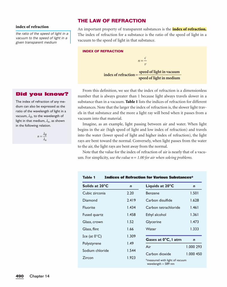
THE LAW OF REFRACTION
An important property of transparent substances is the
The index of refraction for a substance is the ratio of the speed of light in a
vacuum to the speed of light in that substance.
From this definition, we see that the index of refraction is a dimensionless
number that is always greater than 1 because light always travels slower in a
substance than in a vacuum. Table 1 lists the indices of refraction for different
substances. Note that the larger the index of refraction is, the slower light trav-
els in that substance and the more a light ray will bend when it passes from a
vacuum into that material.
Imagine, as an example, light passing between air and water. When light
begins in the air (high speed of light and low index of refraction) and travels
into the water (lower speed of light and higher index of refraction), the light
rays are bent toward the normal. Conversely, when light passes from the water
to the air, the light rays are bent away from the normal.
Note that the value for the index of refraction of air is nearly that of a vacu-
um. For simplicity, use the value n = 1.00 for air when solving problems.
INDEX OF REFRACTION
n = v
c
index of refraction =speed of light in vacuumspeed of light in medium
index of refraction.
Chapter 14490
Table 1 Indices of Refraction for Various Substances*
index of refraction
the ratio of the speed of light in avacuum to the speed of light in agiven transparent medium
Solids at 20°C n
Cubic zirconia 2.20
Diamond 2.4 19
Fluorite 1 .434
Fused quartz 1 .458
Glass, crown 1 .52
Glass, flint 1 .66
Ice (at 0°C) 1 .309
Polystyrene 1 .49
Sodium chloride 1 .544
Zircon 1 .923
Liquids at 20°C n
Benzene 1 .50 1
Carbon disulfide 1 .628
Carbon tetrachloride 1 .46 1
Ethyl alcohol 1 .36 1
Glycerine 1 .473
Water 1 .333
Gases at 0°C, 1 atm n
Air 1 .000 293
Carbon dioxide 1 .000 450
*measured with light of vacuum wavelength = 589 nm
The index of refraction of any me-dium can also be expressed as theratio of the wavelength of light in avacuum, l0 , to the wavelength oflight in that medium, ln , as shownin the following relation.
n = ll
0
n
Did you know?
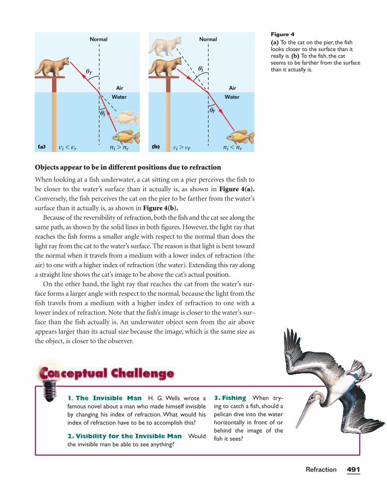
Objects appear to be in different positions due to refraction
When looking at a fish underwater, a cat sitting on a pier perceives the fish to
be closer to the water’s surface than it actually is, as shown in Figure 4(a).Conversely, the fish perceives the cat on the pier to be farther from the water’s
surface than it actually is, as shown in Figure 4(b).Because of the reversibility of refraction, both the fish and the cat see along the
same path, as shown by the solid lines in both figures. However, the light ray that
reaches the fish forms a smaller angle with respect to the normal than does the
light ray from the cat to the water’s surface. The reason is that light is bent toward
the normal when it travels from a medium with a lower index of refraction (the
air) to one with a higher index of refraction (the water). Extending this ray along
a straight line shows the cat’s image to be above the cat’s actual position.
On the other hand, the light ray that reaches the cat from the water’s sur-
face forms a larger angle with respect to the normal, because the light from the
fish travels from a medium with a higher index of refraction to one with a
lower index of refraction. Note that the fish’s image is closer to the water’s sur-
face than the fish actually is. An underwater object seen from the air above
appears larger than its actual size because the image, which is the same size as
the object, is closer to the observer.
491Refraction
Figure 4(a) To the cat on the pier, the fishlooks closer to the surface than itreally is. (b) To the fish, the catseems to be farther from the surfacethan it actually is.
ni < nrvi > vr
Air
Water
Normal
r
(b)
θ
iθ
θ
ni > nrvi < vr
Air
Water
Normal
i
(a)
θ
r θ
3. Fishing When try-ing to catch a fish, should apelican dive into the waterhorizontally in front of orbehind the image of thefish it sees?
1. The Invisible Man H. G. Wells wrote afamous novel about a man who made himself invisibleby changing his index of refraction. What would hisindex of refraction have to be to accomplish this?
2. Visibility for the Invisible Man Wouldthe invisible man be able to see anything?
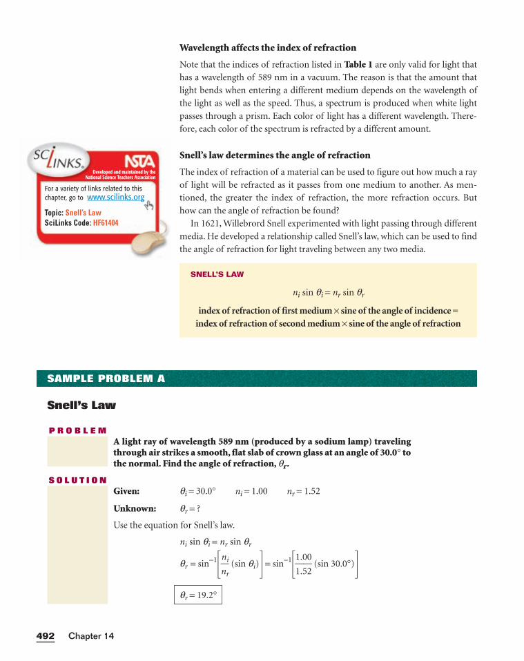
Wavelength affects the index of refraction
Note that the indices of refraction listed in Table 1 are only valid for light that
has a wavelength of 589 nm in a vacuum. The reason is that the amount that
light bends when entering a different medium depends on the wavelength of
the light as well as the speed. Thus, a spectrum is produced when white light
passes through a prism. Each color of light has a different wavelength. There-
fore, each color of the spectrum is refracted by a different amount.
Snell’s law determines the angle of refraction
The index of refraction of a material can be used to figure out how much a ray
of light will be refracted as it passes from one medium to another. As men-
tioned, the greater the index of refraction, the more refraction occurs. But
how can the angle of refraction be found?
In 1621, Willebrord Snell experimented with light passing through different
media. He developed a relationship called Snell’s law, which can be used to find
the angle of refraction for light traveling between any two media.
SNELL’S LAW
ni sin qi = nr sin qr
index of refraction of first medium × sine of the angle of incidence =index of refraction of second medium × sine of the angle of refraction
Chapter 14492
SAMPLE PROBLEM A
Snell’s Law
P R O B L E MA light ray of wavelength 589 nm (produced by a sodium lamp) travelingthrough air strikes a smooth, flat slab of crown glass at an angle of 30.0° tothe normal. Find the angle of refraction, qr.
S O L U T I O NGiven: qi = 30.0° ni = 1.00 nr = 1.52
Unknown: qr = ?
Use the equation for Snell’s law.
ni sin qi = nr sin qr
qr = sin−1�n
n
r
i (sin qi)� = sin−1�1
1
.
.
0
5
0
2 (sin 30.0°)�
qr = 19.2°
Developed and maintained by theNational Science Teachers Association
For a variety of links related to thischapter, go to www.scilinks.org
Topic: Snell’s LawSciLinks Code: HF61404
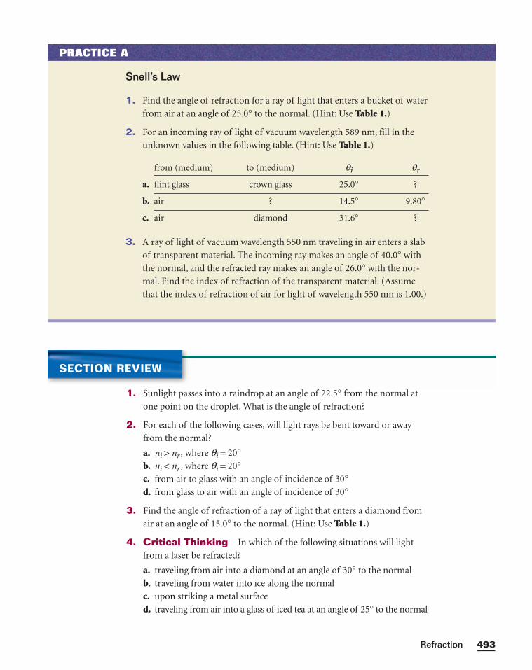
493Refraction
PRACTICE A
Snell’s Law
1. Find the angle of refraction for a ray of light that enters a bucket of water
from air at an angle of 25.0° to the normal. (Hint: Use Table 1.)
2. For an incoming ray of light of vacuum wavelength 589 nm, fill in the
unknown values in the following table. (Hint: Use Table 1.)
from (medium) to (medium) qi qr
a. flint glass crown glass 25.0° ?
b. air ? 14.5° 9.80°
c. air diamond 31.6° ?
3. A ray of light of vacuum wavelength 550 nm traveling in air enters a slab
of transparent material. The incoming ray makes an angle of 40.0° with
the normal, and the refracted ray makes an angle of 26.0° with the nor-
mal. Find the index of refraction of the transparent material. (Assume
that the index of refraction of air for light of wavelength 550 nm is 1.00.)
SECTION REVIEW
1. Sunlight passes into a raindrop at an angle of 22.5° from the normal at
one point on the droplet. What is the angle of refraction?
2. For each of the following cases, will light rays be bent toward or away
from the normal?
a. ni > nr , where qi = 20°b. ni < nr , where qi = 20°c. from air to glass with an angle of incidence of 30°d. from glass to air with an angle of incidence of 30°
3. Find the angle of refraction of a ray of light that enters a diamond from
air at an angle of 15.0° to the normal. (Hint: Use Table 1.)
4. Critical Thinking In which of the following situations will light
from a laser be refracted?
a. traveling from air into a diamond at an angle of 30° to the normal
b. traveling from water into ice along the normal
c. upon striking a metal surface
d. traveling from air into a glass of iced tea at an angle of 25° to the normal
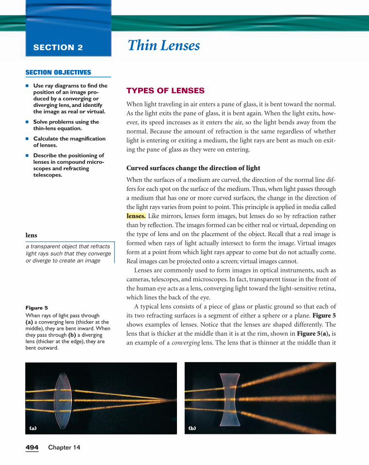
Thin LensesSECTION 2
TYPES OF LENSES
When light traveling in air enters a pane of glass, it is bent toward the normal.
As the light exits the pane of glass, it is bent again. When the light exits, how-
ever, its speed increases as it enters the air, so the light bends away from the
normal. Because the amount of refraction is the same regardless of whether
light is entering or exiting a medium, the light rays are bent as much on exit-
ing the pane of glass as they were on entering.
Curved surfaces change the direction of light
When the surfaces of a medium are curved, the direction of the normal line dif-
fers for each spot on the surface of the medium. Thus, when light passes through
a medium that has one or more curved surfaces, the change in the direction of
the light rays varies from point to point. This principle is applied in media called
Like mirrors, lenses form images, but lenses do so by refraction rather
than by reflection. The images formed can be either real or virtual, depending on
the type of lens and on the placement of the object. Recall that a real image is
formed when rays of light actually intersect to form the image. Virtual images
form at a point from which light rays appear to come but do not actually come.
Real images can be projected onto a screen; virtual images cannot.
Lenses are commonly used to form images in optical instruments, such as
cameras, telescopes, and microscopes. In fact, transparent tissue in the front of
the human eye acts as a lens, converging light toward the light-sensitive retina,
which lines the back of the eye.
A typical lens consists of a piece of glass or plastic ground so that each of
its two refracting surfaces is a segment of either a sphere or a plane. Figure 5shows examples of lenses. Notice that the lenses are shaped differently. The
lens that is thicker at the middle than it is at the rim, shown in Figure 5(a), is
an example of a converging lens. The lens that is thinner at the middle than it
lenses.
Chapter 14494
SECTION OBJECTIVES
■ Use ray diagrams to find theposition of an image pro-duced by a converging ordiverging lens, and identifythe image as real or virtual.
■ Solve problems using thethin-lens equation.
■ Calculate the magnificationof lenses.
■ Describe the positioning oflenses in compound micro-scopes and refracting telescopes.
lens
a transparent object that refractslight rays such that they convergeor diverge to create an image
Figure 5When rays of light pass through (a) a converging lens (thicker at themiddle), they are bent inward. Whenthey pass through (b) a diverginglens (thicker at the edge), they arebent outward.
(a) (b)
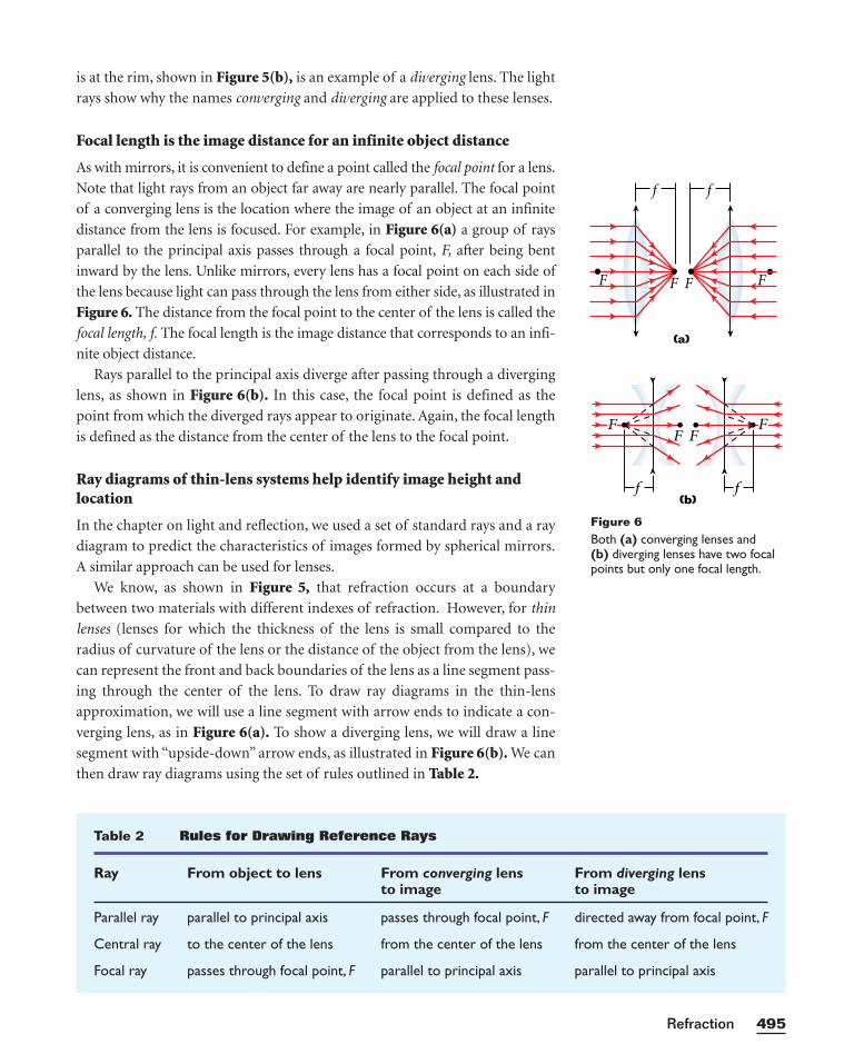
is at the rim, shown in Figure 5(b), is an example of a diverging lens. The light
rays show why the names converging and diverging are applied to these lenses.
Focal length is the image distance for an infinite object distance
As with mirrors, it is convenient to define a point called the focal point for a lens.
Note that light rays from an object far away are nearly parallel. The focal point
of a converging lens is the location where the image of an object at an infinite
distance from the lens is focused. For example, in Figure 6(a) a group of rays
parallel to the principal axis passes through a focal point, F, after being bent
inward by the lens. Unlike mirrors, every lens has a focal point on each side of
the lens because light can pass through the lens from either side, as illustrated in
Figure 6. The distance from the focal point to the center of the lens is called the
focal length, f. The focal length is the image distance that corresponds to an infi-
nite object distance.
Rays parallel to the principal axis diverge after passing through a diverging
lens, as shown in Figure 6(b). In this case, the focal point is defined as the
point from which the diverged rays appear to originate. Again, the focal length
is defined as the distance from the center of the lens to the focal point.
Ray diagrams of thin-lens systems help identify image height andlocation
In the chapter on light and reflection, we used a set of standard rays and a ray
diagram to predict the characteristics of images formed by spherical mirrors.
A similar approach can be used for lenses.
We know, as shown in Figure 5, that refraction occurs at a boundary
between two materials with different indexes of refraction. However, for thin
lenses (lenses for which the thickness of the lens is small compared to the
radius of curvature of the lens or the distance of the object from the lens), we
can represent the front and back boundaries of the lens as a line segment pass-
ing through the center of the lens. To draw ray diagrams in the thin-lens
approximation, we will use a line segment with arrow ends to indicate a con-
verging lens, as in Figure 6(a). To show a diverging lens, we will draw a line
segment with “upside-down” arrow ends, as illustrated in Figure 6(b). We can
then draw ray diagrams using the set of rules outlined in Table 2.
495Refraction
Table 2 Rules for Drawing Reference Rays
Ray From object to lens From converging lens From diverging lensto image to image
Parallel ray parallel to principal axis passes through focal point, F directed away from focal point, F
Central ray to the center of the lens from the center of the lens from the center of the lens
Focal ray passes through focal point, F parallel to principal axis parallel to principal axis
Figure 6Both (a) converging lenses and (b) diverging lenses have two focalpoints but only one focal length.
(a)
FFF
ff
F
(b)
F
f
F
f
FF
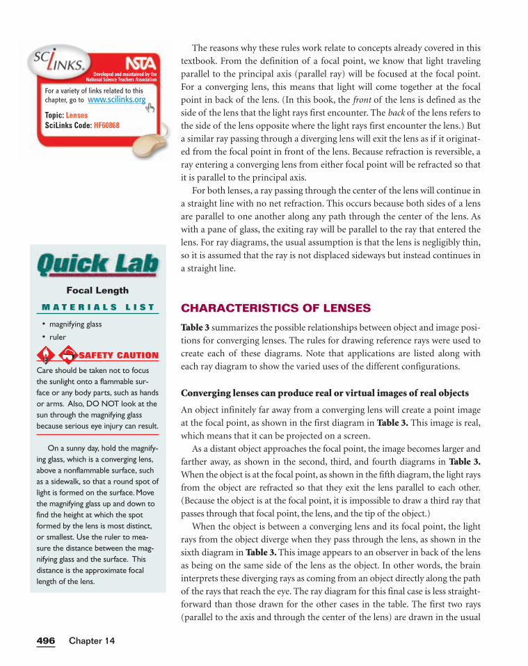
The reasons why these rules work relate to concepts already covered in this
textbook. From the definition of a focal point, we know that light traveling
parallel to the principal axis (parallel ray) will be focused at the focal point.
For a converging lens, this means that light will come together at the focal
point in back of the lens. (In this book, the front of the lens is defined as the
side of the lens that the light rays first encounter. The back of the lens refers to
the side of the lens opposite where the light rays first encounter the lens.) But
a similar ray passing through a diverging lens will exit the lens as if it originat-
ed from the focal point in front of the lens. Because refraction is reversible, a
ray entering a converging lens from either focal point will be refracted so that
it is parallel to the principal axis.
For both lenses, a ray passing through the center of the lens will continue in
a straight line with no net refraction. This occurs because both sides of a lens
are parallel to one another along any path through the center of the lens. As
with a pane of glass, the exiting ray will be parallel to the ray that entered the
lens. For ray diagrams, the usual assumption is that the lens is negligibly thin,
so it is assumed that the ray is not displaced sideways but instead continues in
a straight line.
CHARACTERISTICS OF LENSES
Table 3 summarizes the possible relationships between object and image posi-
tions for converging lenses. The rules for drawing reference rays were used to
create each of these diagrams. Note that applications are listed along with
each ray diagram to show the varied uses of the different configurations.
Converging lenses can produce real or virtual images of real objects
An object infinitely far away from a converging lens will create a point image
at the focal point, as shown in the first diagram in Table 3. This image is real,
which means that it can be projected on a screen.
As a distant object approaches the focal point, the image becomes larger and
farther away, as shown in the second, third, and fourth diagrams in Table 3.When the object is at the focal point, as shown in the fifth diagram, the light rays
from the object are refracted so that they exit the lens parallel to each other.
(Because the object is at the focal point, it is impossible to draw a third ray that
passes through that focal point, the lens, and the tip of the object.)
When the object is between a converging lens and its focal point, the light
rays from the object diverge when they pass through the lens, as shown in the
sixth diagram in Table 3. This image appears to an observer in back of the lens
as being on the same side of the lens as the object. In other words, the brain
interprets these diverging rays as coming from an object directly along the path
of the rays that reach the eye. The ray diagram for this final case is less straight-
forward than those drawn for the other cases in the table. The first two rays
(parallel to the axis and through the center of the lens) are drawn in the usual
Chapter 14496
Developed and maintained by theNational Science Teachers Association
For a variety of links related to thischapter, go to www.scilinks.org
Topic: LensesSciLinks Code: HF60868
Focal Length
M A T E R I A L S L I S T
• magnifying glass
• ruler
SAFETY CAUTION
Care should be taken not to focusthe sunlight onto a flammable sur-face or any body parts, such as handsor arms. Also, DO NOT look at thesun through the magnifying glassbecause serious eye injury can result.
On a sunny day, hold the magnify-ing glass, which is a converging lens,above a nonflammable surface, suchas a sidewalk, so that a round spot oflight is formed on the surface. Movethe magnifying glass up and down tofind the height at which the spotformed by the lens is most distinct,or smallest. Use the ruler to mea-sure the distance between the mag-nifying glass and the surface. Thisdistance is the approximate focallength of the lens.
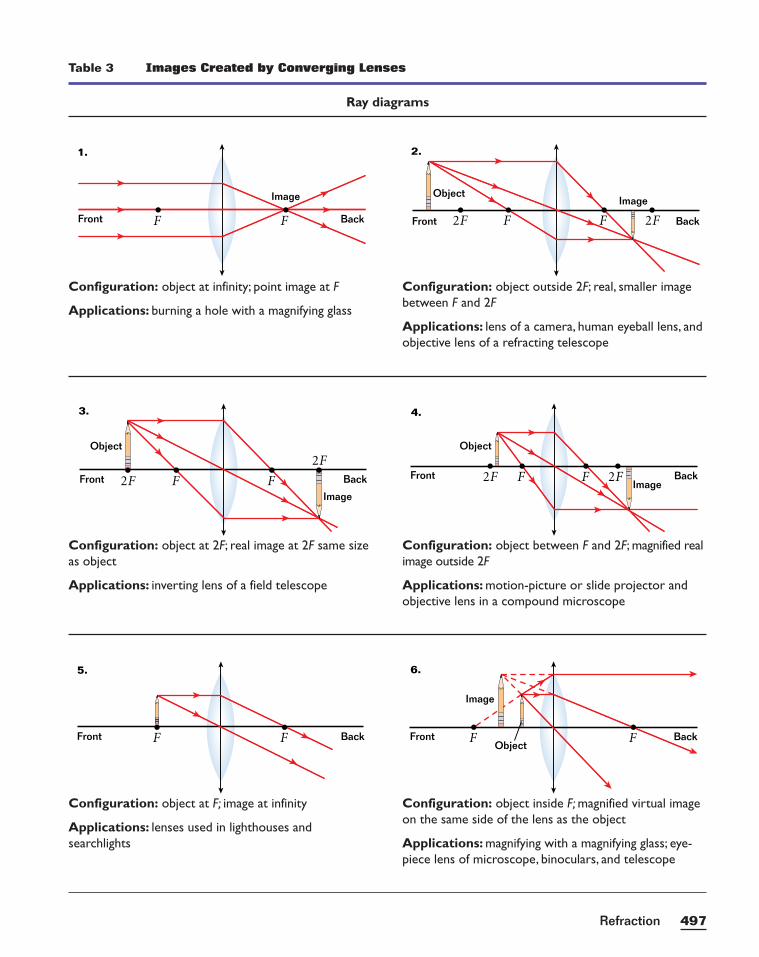
497Refraction
Table 3 Images Created by Converging Lenses
Ray diagrams
ObjectBackFront
Image
FF
6.
BackFront F F
5.
BackImage
Object
Front 2F2F FF
4.
Back
Image
Object
Front 2F F
2F
F
3.
Back
ImageObject
Front 2F 2FFF
2.
BackFront
Image
F F
1.
Configuration: object outside 2F; real, smaller imagebetween F and 2F
Applications: lens of a camera, human eyeball lens, and objective lens of a refracting telescope
Configuration: object at infinity; point image at F
Applications: burning a hole with a magnifying glass
Configuration: object between F and 2F; magnified realimage outside 2F
Applications: motion-picture or slide projector andobjective lens in a compound microscope
Configuration: object at 2F; real image at 2F same size as object
Applications: inverting lens of a field telescope
Configuration: object inside F; magnified virtual imageon the same side of the lens as the object
Applications: magnifying with a magnifying glass; eye-piece lens of microscope, binoculars, and telescope
Configuration: object at F; image at infinity
Applications: lenses used in lighthouses and searchlights
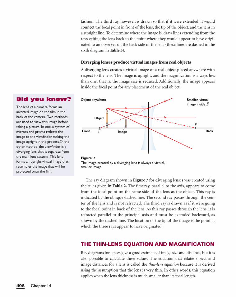
fashion. The third ray, however, is drawn so that if it were extended, it would
connect the focal point in front of the lens, the tip of the object, and the lens in
a straight line. To determine where the image is, draw lines extending from the
rays exiting the lens back to the point where they would appear to have origi-
nated to an observer on the back side of the lens (these lines are dashed in the
sixth diagram in Table 3).
Diverging lenses produce virtual images from real objects
A diverging lens creates a virtual image of a real object placed anywhere with
respect to the lens. The image is upright, and the magnification is always less
than one; that is, the image size is reduced. Additionally, the image appears
inside the focal point for any placement of the real object.
The ray diagram shown in Figure 7 for diverging lenses was created using
the rules given in Table 2. The first ray, parallel to the axis, appears to come
from the focal point on the same side of the lens as the object. This ray is
indicated by the oblique dashed line. The second ray passes through the cen-
ter of the lens and is not refracted. The third ray is drawn as if it were going
to the focal point in back of the lens. As this ray passes through the lens, it is
refracted parallel to the principal axis and must be extended backward, as
shown by the dashed line. The location of the tip of the image is the point at
which the three rays appear to have originated.
THE THIN-LENS EQUATION AND MAGNIFICATION
Ray diagrams for lenses give a good estimate of image size and distance, but it is
also possible to calculate these values. The equation that relates object and
image distances for a lens is called the thin-lens equation because it is derived
using the assumption that the lens is very thin. In other words, this equation
applies when the lens thickness is much smaller than its focal length.
Chapter 14498
Object anywhere
Front
Object
BackImage
Smaller, virtualimage inside F
F
F
Figure 7The image created by a diverging lens is always a virtual,smaller image.
The lens of a camera forms aninverted image on the film in theback of the camera. Two methodsare used to view this image beforetaking a picture. In one, a system ofmirrors and prisms reflects theimage to the viewfinder, making theimage upright in the process. In theother method, the viewfinder is adiverging lens that is separate fromthe main lens system. This lensforms an upright virtual image thatresembles the image that will beprojected onto the film.
Did you know?
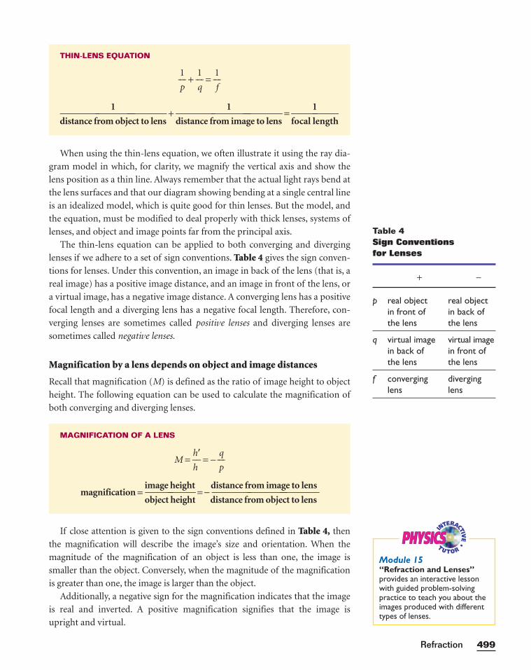
When using the thin-lens equation, we often illustrate it using the ray dia-
gram model in which, for clarity, we magnify the vertical axis and show the
lens position as a thin line. Always remember that the actual light rays bend at
the lens surfaces and that our diagram showing bending at a single central line
is an idealized model, which is quite good for thin lenses. But the model, and
the equation, must be modified to deal properly with thick lenses, systems of
lenses, and object and image points far from the principal axis.
The thin-lens equation can be applied to both converging and diverging
lenses if we adhere to a set of sign conventions. Table 4 gives the sign conven-
tions for lenses. Under this convention, an image in back of the lens (that is, a
real image) has a positive image distance, and an image in front of the lens, or
a virtual image, has a negative image distance. A converging lens has a positive
focal length and a diverging lens has a negative focal length. Therefore, con-
verging lenses are sometimes called positive lenses and diverging lenses are
sometimes called negative lenses.
Magnification by a lens depends on object and image distances
Recall that magnification (M) is defined as the ratio of image height to object
height. The following equation can be used to calculate the magnification of
both converging and diverging lenses.
If close attention is given to the sign conventions defined in Table 4, then
the magnification will describe the image’s size and orientation. When the
magnitude of the magnification of an object is less than one, the image is
smaller than the object. Conversely, when the magnitude of the magnification
is greater than one, the image is larger than the object.
Additionally, a negative sign for the magnification indicates that the image
is real and inverted. A positive magnification signifies that the image is
upright and virtual.
MAGNIFICATION OF A LENS
M = ⎯h
h
�⎯ = − ⎯⎯
p
q⎯⎯
magnification =image height distance from image to lens⎯⎯ = − ⎯⎯⎯object height distance from object to lens
THIN-LENS EQUATION
⎯⎯p
1⎯⎯ + ⎯⎯
1
q⎯⎯ = ⎯⎯
1
f⎯⎯
1 1 1⎯⎯⎯ + ⎯⎯⎯ = ⎯⎯
distance from object to lens distance from image to lens focal length
499Refraction
Table 4Sign Conventions for Lenses
+ −
p real object real object in front of in back of the lens the lens
q virtual image virtual imagein back of in front ofthe lens the lens
f converging diverginglens lens
PHYSICSPHYSICSModule 15“Refraction and Lenses”provides an interactive lessonwith guided problem-solvingpractice to teach you about theimages produced with differenttypes of lenses.
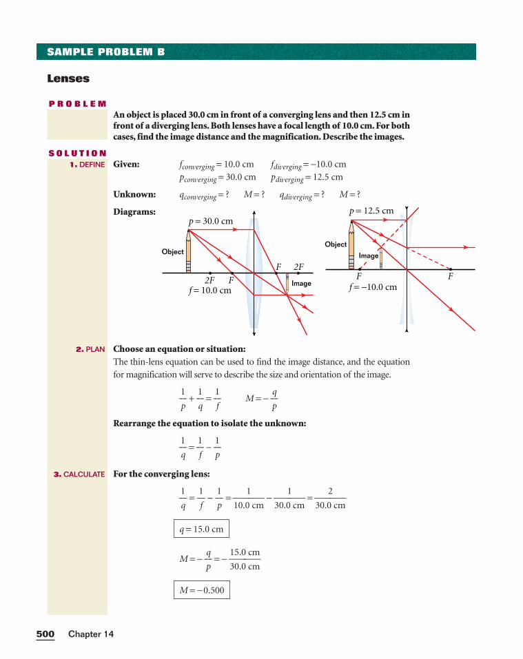
Chapter 14500
SAMPLE PROBLEM B
Lenses
P R O B L E MAn object is placed 30.0 cm in front of a converging lens and then 12.5 cm infront of a diverging lens. Both lenses have a focal length of 10.0 cm. For bothcases, find the image distance and the magnification. Describe the images.
S O L U T I O NGiven: fconverging = 10.0 cm fdiverging = −10.0 cm
pconverging = 30.0 cm pdiverging = 12.5 cm
Unknown: qconverging = ? M = ? qdiverging = ? M = ?
Diagrams:
Choose an equation or situation:The thin-lens equation can be used to find the image distance, and the equation
for magnification will serve to describe the size and orientation of the image.
p
1 +
1
q =
1
f M = −
p
q
Rearrange the equation to isolate the unknown:
1
q =
1
f −
p
1
For the converging lens:
1
q =
1
f −
p
1 =
10.0
1
cm −
30.0
1
cm =
30.0
2
cm
M = − p
q = −
1
3
5
0
.
.
0
0
c
c
m
m
M = −0.500
q = 15.0 cm
f = 10.0 cm
p = 30.0 cm
F2F
F 2F
Object
Image
1. DEFINE
2. PLAN
3. CALCULATE
Ff = −10.0 cm
p = 12.5 cm
F
Object
Image
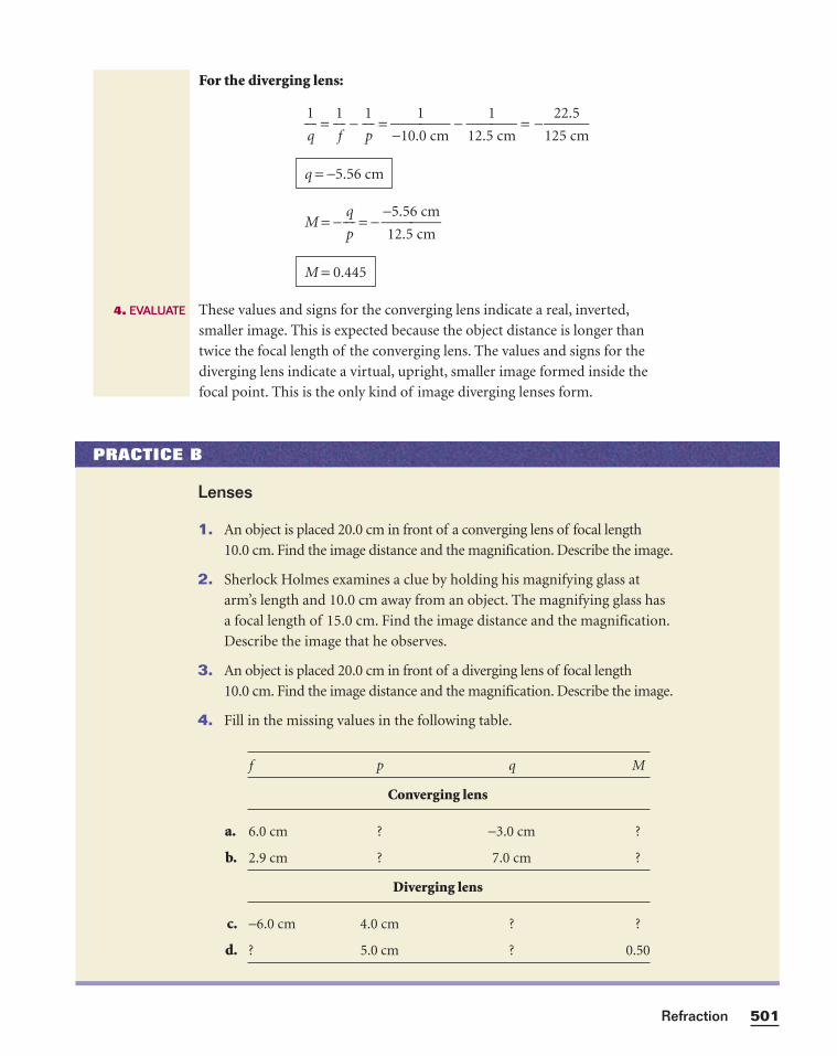
501Refraction
For the diverging lens:
1
q =
1
f −
p
1 =
−10.
1
0 cm −
12.5
1
cm = −
M = − p
q = −
−1
5
2
.
.
5
5
6
c
c
m
m
These values and signs for the converging lens indicate a real, inverted,
smaller image. This is expected because the object distance is longer than
twice the focal length of the converging lens. The values and signs for the
diverging lens indicate a virtual, upright, smaller image formed inside the
focal point. This is the only kind of image diverging lenses form.
M = 0.445
q = −5.56 cm
22.5125 cm
4. EVALUATE
PRACTICE B
Lenses
1. An object is placed 20.0 cm in front of a converging lens of focal length
10.0 cm. Find the image distance and the magnification. Describe the image.
2. Sherlock Holmes examines a clue by holding his magnifying glass at
arm’s length and 10.0 cm away from an object. The magnifying glass has
a focal length of 15.0 cm. Find the image distance and the magnification.
Describe the image that he observes.
3. An object is placed 20.0 cm in front of a diverging lens of focal length
10.0 cm. Find the image distance and the magnification. Describe the image.
4. Fill in the missing values in the following table.
f p q M
Converging lens
6.0 cm ? −3.0 cm ?
2.9 cm ? 7.0 cm ?
Diverging lens
−6.0 cm 4.0 cm ? ?
? 5.0 cm ? 0.50
b.
a.
c.
d.
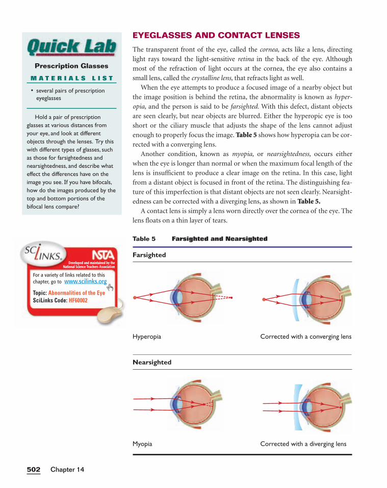
EYEGLASSES AND CONTACT LENSES
The transparent front of the eye, called the cornea, acts like a lens, directing
light rays toward the light-sensitive retina in the back of the eye. Although
most of the refraction of light occurs at the cornea, the eye also contains a
small lens, called the crystalline lens, that refracts light as well.
When the eye attempts to produce a focused image of a nearby object but
the image position is behind the retina, the abnormality is known as hyper-
opia, and the person is said to be farsighted. With this defect, distant objects
are seen clearly, but near objects are blurred. Either the hyperopic eye is too
short or the ciliary muscle that adjusts the shape of the lens cannot adjust
enough to properly focus the image. Table 5 shows how hyperopia can be cor-
rected with a converging lens.
Another condition, known as myopia, or nearsightedness, occurs either
when the eye is longer than normal or when the maximum focal length of the
lens is insufficient to produce a clear image on the retina. In this case, light
from a distant object is focused in front of the retina. The distinguishing fea-
ture of this imperfection is that distant objects are not seen clearly. Nearsight-
edness can be corrected with a diverging lens, as shown in Table 5.A contact lens is simply a lens worn directly over the cornea of the eye. The
lens floats on a thin layer of tears.
Chapter 14502
Table 5 Farsighted and Nearsighted
Farsighted
Hyperopia Corrected with a converging lens
Nearsighted
Myopia Corrected with a diverging lens
Prescription Glasses
M A T E R I A L S L I S T
• several pairs of prescriptioneyeglasses
Hold a pair of prescription glasses at various distances fromyour eye, and look at differentobjects through the lenses. Try thiswith different types of glasses, suchas those for farsightedness andnearsightedness, and describe whateffect the differences have on theimage you see. If you have bifocals,how do the images produced by thetop and bottom portions of thebifocal lens compare?
Developed and maintained by theNational Science Teachers Association
For a variety of links related to thischapter, go to www.scilinks.org
Topic: Abnormalities of the EyeSciLinks Code: HF60002
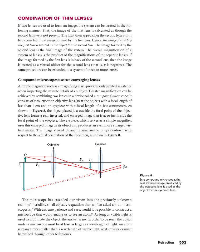
COMBINATION OF THIN LENSES
If two lenses are used to form an image, the system can be treated in the fol-
lowing manner. First, the image of the first lens is calculated as though the
second lens were not present. The light then approaches the second lens as if it
had come from the image formed by the first lens. Hence, the image formed by
the first lens is treated as the object for the second lens. The image formed by the
second lens is the final image of the system. The overall magnification of a
system of lenses is the product of the magnifications of the separate lenses. If
the image formed by the first lens is in back of the second lens, then the image
is treated as a virtual object for the second lens (that is, p is negative). The
same procedure can be extended to a system of three or more lenses.
Compound microscopes use two converging lenses
A simple magnifier, such as a magnifying glass, provides only limited assistance
when inspecting the minute details of an object. Greater magnification can be
achieved by combining two lenses in a device called a compound microscope. It
consists of two lenses: an objective lens (near the object) with a focal length of
less than 1 cm and an eyepiece with a focal length of a few centimeters. As
shown in Figure 8, the object placed just outside the focal point of the objec-
tive lens forms a real, inverted, and enlarged image that is at or just inside the
focal point of the eyepiece. The eyepiece, which serves as a simple magnifier,
uses this enlarged image as its object and produces an even more enlarged vir-
tual image. The image viewed through a microscope is upside-down with
respect to the actual orientation of the specimen, as shown in Figure 8.
The microscope has extended our vision into the previously unknown
realm of incredibly small objects. A question that is often asked about micro-
scopes is, “With extreme patience and care, would it be possible to construct a
microscope that would enable us to see an atom?” As long as visible light is
used to illuminate the object, the answer is no. In order to be seen, the object
under a microscope must be at least as large as a wavelength of light. An atom
is many times smaller than a wavelength of visible light, so its mysteries must
be probed through other techniques.
503Refraction
Eyepiece
I1
I2
OFe
Fo
Objective
Figure 8In a compound microscope, thereal, inverted image produced bythe objective lens is used as theobject for the eyepiece lens.
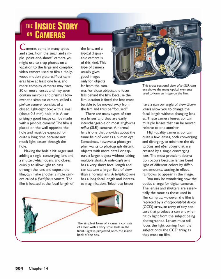
Chapter 14504
THE INSIDE STORYON CAMERAS
Cameras come in many typesand sizes, from the small and sim-ple “point-and-shoot” camera youmight use to snap photos on avacation to the large and complexvideo camera used to film a Holly-wood motion picture. Most cam-eras have at least one lens, andmore complex cameras may have30 or more lenses and may evencontain mirrors and prisms. How-ever, the simplest camera, called apinhole camera, consists of aclosed, light-tight box with a small(about 0.5 mm) hole in it. A sur-prisingly good image can be madewith a pinhole camera! The film isplaced on the wall opposite thehole and must be exposed forquite a long time because notmuch light passes through thehole.
Making the hole a bit larger andadding a single, converging lens anda shutter, which opens and closesquickly to allow light to passthrough the lens and expose thefilm, can make another simple cam-era called a fixed-focus camera. Thefilm is located at the focal length of
the lens, and a typical dispos-able camera is of this kind. This type of camera usually gives good images only for objects far from the cam-era. For close objects, the focusfalls behind the film. Because thefilm location is fixed, the lens mustbe able to be moved away fromthe film and thus be “focused.”
There are many types of cam-era lenses, and they are easilyinterchangeable on most single-lensreflex (SLR) cameras. A normallens is one that provides about thesame field of view as a human eye.Sometimes, however, a photogra-pher wants to photograph distantobjects with more detail or cap-ture a larger object without takingmultiple shots. A wide-angle lenshas a very short focal length andcan capture a larger field of viewthan a normal lens. A telephoto lenshas a long focal length and increas-es magnification. Telephoto lenses
have a narrow angle of view. Zoomlenses allow you to change thefocal length without changing lens-es. These camera lenses containmultiple lenses that can be movedrelative to one another.
High-quality cameras containquite a few lenses, both convergingand diverging, to minimize the dis-tortions and aberrations that arecreated by a single converginglens. The most prevalent aberra-tion occurs because lenses bendlight of different colors by differ-ent amounts, causing, in effect,rainbows to appear in the image.
You may be wondering how theoptics change for digital cameras.The lenses and shutters are essen-tially the same as those used infilm cameras. However, the film isreplaced by a charge-coupled device(CCD) array, an array of tiny sen-sors that produce a current whenhit by light from the subject beingphotographed. Lenses must stillfocus the light coming from thesubject onto the CCD array, asthey must on film.
This cross-sectional view of an SLR cam-era shows the many optical elementsused to form an image on the film.
The simplest form of a camera consistsof a box with a very small hole in thefront. Light is projected onto the insideback of the box.
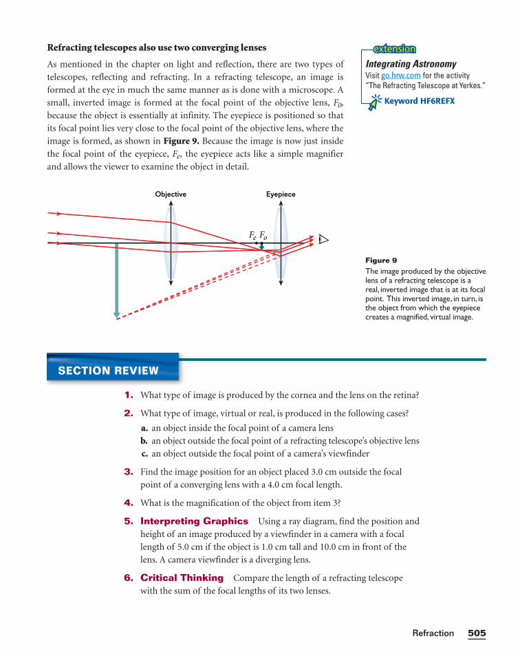
Refracting telescopes also use two converging lenses
As mentioned in the chapter on light and reflection, there are two types of
telescopes, reflecting and refracting. In a refracting telescope, an image is
formed at the eye in much the same manner as is done with a microscope. A
small, inverted image is formed at the focal point of the objective lens, F0,
because the object is essentially at infinity. The eyepiece is positioned so that
its focal point lies very close to the focal point of the objective lens, where the
image is formed, as shown in Figure 9. Because the image is now just inside
the focal point of the eyepiece, Fe, the eyepiece acts like a simple magnifier
and allows the viewer to examine the object in detail.
505Refraction
Figure 9The image produced by the objectivelens of a refracting telescope is areal, inverted image that is at its focalpoint. This inverted image, in turn, isthe object from which the eyepiececreates a magnified, virtual image.
EyepieceObjective
Fe Fo
SECTION REVIEW
1. What type of image is produced by the cornea and the lens on the retina?
2. What type of image, virtual or real, is produced in the following cases?
a. an object inside the focal point of a camera lens
b. an object outside the focal point of a refracting telescope’s objective lens
c. an object outside the focal point of a camera’s viewfinder
3. Find the image position for an object placed 3.0 cm outside the focal
point of a converging lens with a 4.0 cm focal length.
4. What is the magnification of the object from item 3?
5. Interpreting Graphics Using a ray diagram, find the position and
height of an image produced by a viewfinder in a camera with a focal
length of 5.0 cm if the object is 1.0 cm tall and 10.0 cm in front of the
lens. A camera viewfinder is a diverging lens.
6. Critical Thinking Compare the length of a refracting telescope
with the sum of the focal lengths of its two lenses.
Integrating AstronomyVisit go.hrw.com for the activity“The Refracting Telescope at Yerkes.”
Keyword HF6REFX
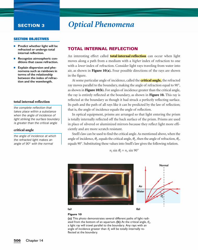
Optical PhenomenaSECTION 3
TOTAL INTERNAL REFLECTION
An interesting effect called can occur when light
moves along a path from a medium with a higher index of refraction to one
with a lower index of refraction. Consider light rays traveling from water into
air, as shown in Figure 10(a). Four possible directions of the rays are shown
in the figure.
At some particular angle of incidence, called the the refracted
ray moves parallel to the boundary, making the angle of refraction equal to 90°,
as shown in Figure 10(b). For angles of incidence greater than the critical angle,
the ray is entirely reflected at the boundary, as shown in Figure 10. This ray is
reflected at the boundary as though it had struck a perfectly reflecting surface.
Its path and the path of all rays like it can be predicted by the law of reflection;
that is, the angle of incidence equals the angle of reflection.
In optical equipment, prisms are arranged so that light entering the prism
is totally internally reflected off the back surface of the prism. Prisms are used
in place of silvered or aluminized mirrors because they reflect light more effi-
ciently and are more scratch resistant.
Snell’s law can be used to find the critical angle. As mentioned above, when the
angle of incidence, qi , equals the critical angle, qc , then the angle of refraction, qr ,
equals 90°. Substituting these values into Snell’s law gives the following relation.
ni sin qc = nr sin 90°
critical angle,
total internal reflection
Chapter 14506
SECTION OBJECTIVES
■ Predict whether light will berefracted or undergo totalinternal reflection.
■ Recognize atmospheric con-ditions that cause refraction.
■ Explain dispersion and phe-nomena such as rainbows interms of the relationshipbetween the index of refrac-tion and the wavelength.
Figure 10(a) This photo demonstrates several different paths of light radi-ated from the bottom of an aquarium. (b) At the critical angle, qc ,a light ray will travel parallel to the boundary. Any rays with anangle of incidence greater than qc will be totally internally re-flected at the boundary.
Air
Normal
Water
cθ
(a) (b)
total internal reflection
the complete reflection thattakes place within a substancewhen the angle of incidence oflight striking the surface boundaryis greater than the critical angle
critical angle
the angle of incidence at whichthe refracted light makes anangle of 90° with the normal
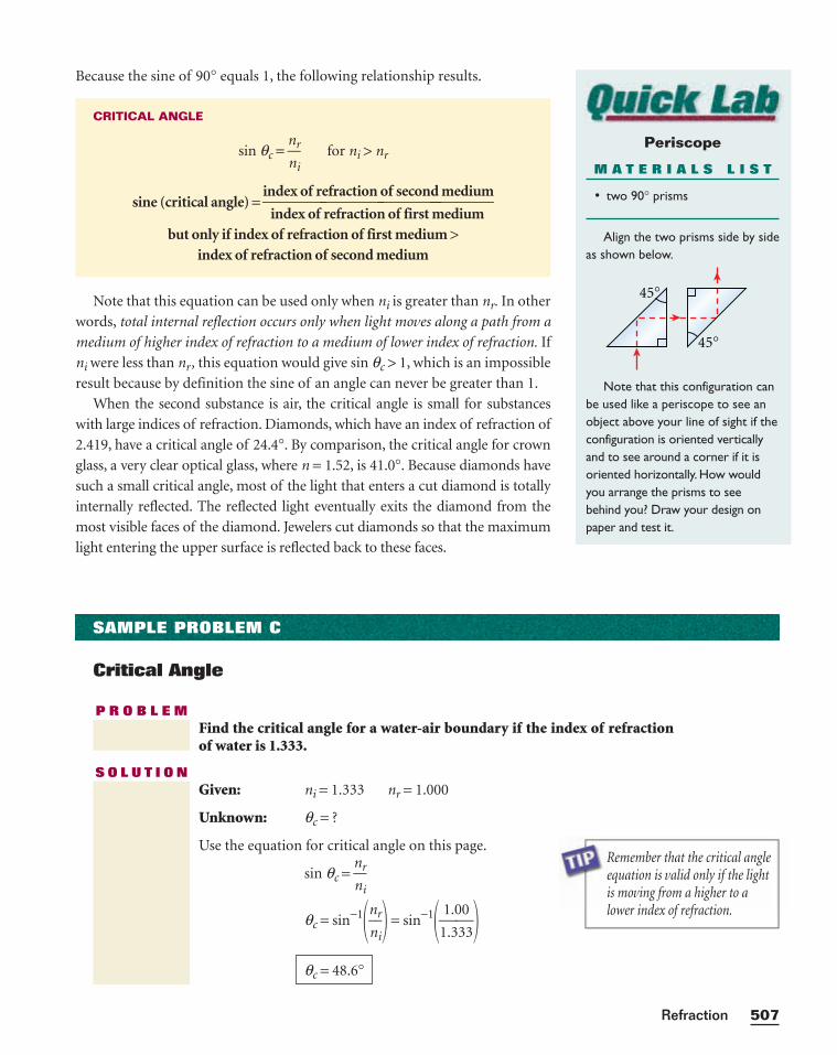
Because the sine of 90° equals 1, the following relationship results.
Note that this equation can be used only when ni is greater than nr. In other
words, total internal reflection occurs only when light moves along a path from a
medium of higher index of refraction to a medium of lower index of refraction. If
ni were less than nr, this equation would give sin qc > 1, which is an impossible
result because by definition the sine of an angle can never be greater than 1.
When the second substance is air, the critical angle is small for substances
with large indices of refraction. Diamonds, which have an index of refraction of
2.419, have a critical angle of 24.4°. By comparison, the critical angle for crown
glass, a very clear optical glass, where n = 1.52, is 41.0°. Because diamonds have
such a small critical angle, most of the light that enters a cut diamond is totally
internally reflected. The reflected light eventually exits the diamond from the
most visible faces of the diamond. Jewelers cut diamonds so that the maximum
light entering the upper surface is reflected back to these faces.
CRITICAL ANGLE
sin qc = n
nr
i for ni > nr
sine (critical angle) =index of refraction of second mediumindex of refraction of first medium
but only if index of refraction of first medium >index of refraction of second medium
507Refraction
SAMPLE PROBLEM C
Critical Angle
P R O B L E MFind the critical angle for a water-air boundary if the index of refractionof water is 1.333.
S O L U T I O NGiven: ni = 1.333 nr = 1.000
Unknown: qc = ?
Use the equation for critical angle on this page.
sin qc = n
nr
i
qc = sin−1�n
nr
i� = sin−1�11..30303�
qc = 48.6°
Remember that the critical angleequation is valid only if the lightis moving from a higher to alower index of refraction.
Periscope
M A T E R I A L S L I S T
• two 90° prisms
Align the two prisms side by sideas shown below.
Note that this configuration canbe used like a periscope to see anobject above your line of sight if theconfiguration is oriented verticallyand to see around a corner if it isoriented horizontally. How wouldyou arrange the prisms to seebehind you? Draw your design onpaper and test it.
45°
45°
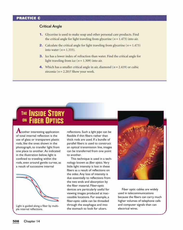
Another interesting applicationof total internal reflection is theuse of glass or transparent plasticrods, like the ones shown in thephotograph, to transfer light fromone place to another. As indicatedin the illustration below, light isconfined to traveling within therods, even around gentle curves, asa result of successive internal
reflections. Such a light pipe can beflexible if thin fibers rather thanthick rods are used. If a bundle ofparallel fibers is used to constructan optical transmission line, imagescan be transferred from one pointto another.
This technique is used in a tech-nology known as fiber optics.Verylittle light intensity is lost in thesefibers as a result of reflections onthe sides. Any loss of intensity isdue essentially to reflections fromthe two ends and absorption bythe fiber material. Fiber-opticdevices are particularly useful forviewing images produced at inac-cessible locations. For example, afiber-optic cable can be threadedthrough the esophagus and intothe stomach to look for ulcers.
Fiber optic cables are widelyused in telecommunicationsbecause the fibers can carry muchhigher volumes of telephone callsand computer signals than canelectrical wires.
Chapter 14508
PRACTICE C
Critical Angle
1. Glycerine is used to make soap and other personal care products. Find
the critical angle for light traveling from glycerine (n = 1.473) into air.
2. Calculate the critical angle for light traveling from glycerine (n = 1.473)
into water (n = 1.333).
3. Ice has a lower index of refraction than water. Find the critical angle for
light traveling from ice (n = 1.309) into air.
4. Which has a smaller critical angle in air, diamond (n = 2.419) or cubic
zirconia (n = 2.20)? Show your work.
(b)
Light is guided along a fiber by multi-ple internal reflections.
THE INSIDE STORYON FIBER OPTICS
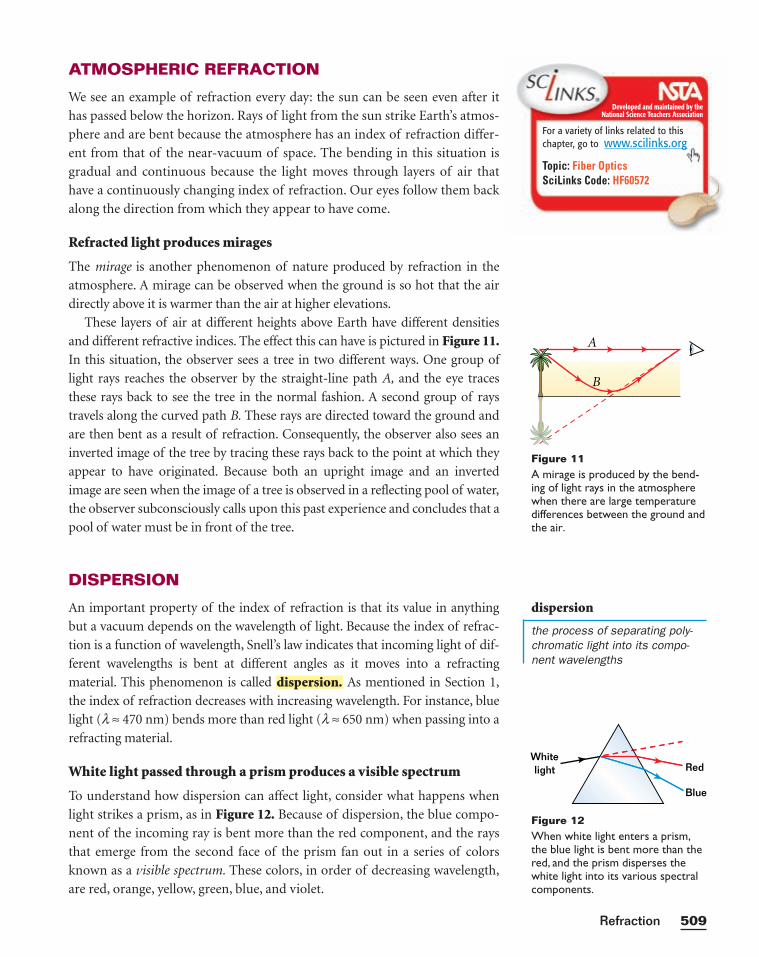
ATMOSPHERIC REFRACTION
We see an example of refraction every day: the sun can be seen even after it
has passed below the horizon. Rays of light from the sun strike Earth’s atmos-
phere and are bent because the atmosphere has an index of refraction differ-
ent from that of the near-vacuum of space. The bending in this situation is
gradual and continuous because the light moves through layers of air that
have a continuously changing index of refraction. Our eyes follow them back
along the direction from which they appear to have come.
Refracted light produces mirages
The mirage is another phenomenon of nature produced by refraction in the
atmosphere. A mirage can be observed when the ground is so hot that the air
directly above it is warmer than the air at higher elevations.
These layers of air at different heights above Earth have different densities
and different refractive indices. The effect this can have is pictured in Figure 11.In this situation, the observer sees a tree in two different ways. One group of
light rays reaches the observer by the straight-line path A, and the eye traces
these rays back to see the tree in the normal fashion. A second group of rays
travels along the curved path B. These rays are directed toward the ground and
are then bent as a result of refraction. Consequently, the observer also sees an
inverted image of the tree by tracing these rays back to the point at which they
appear to have originated. Because both an upright image and an inverted
image are seen when the image of a tree is observed in a reflecting pool of water,
the observer subconsciously calls upon this past experience and concludes that a
pool of water must be in front of the tree.
DISPERSION
An important property of the index of refraction is that its value in anything
but a vacuum depends on the wavelength of light. Because the index of refrac-
tion is a function of wavelength, Snell’s law indicates that incoming light of dif-
ferent wavelengths is bent at different angles as it moves into a refracting
material. This phenomenon is called As mentioned in Section 1,
the index of refraction decreases with increasing wavelength. For instance, blue
light (l ≈ 470 nm) bends more than red light (l ≈ 650 nm) when passing into a
refracting material.
White light passed through a prism produces a visible spectrum
To understand how dispersion can affect light, consider what happens when
light strikes a prism, as in Figure 12. Because of dispersion, the blue compo-
nent of the incoming ray is bent more than the red component, and the rays
that emerge from the second face of the prism fan out in a series of colors
known as a visible spectrum. These colors, in order of decreasing wavelength,
are red, orange, yellow, green, blue, and violet.
dispersion.
509Refraction
Developed and maintained by theNational Science Teachers Association
For a variety of links related to thischapter, go to www.scilinks.org
Topic: Fiber OpticsSciLinks Code: HF60572
Whitelight Red
Blue
Figure 12When white light enters a prism,the blue light is bent more than thered, and the prism disperses thewhite light into its various spectralcomponents.
A
B
Figure 11A mirage is produced by the bend-ing of light rays in the atmospherewhen there are large temperaturedifferences between the ground andthe air.
dispersion
the process of separating poly-chromatic light into its compo-nent wavelengths
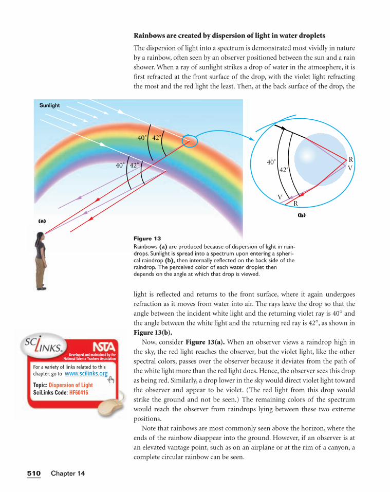
Rainbows are created by dispersion of light in water droplets
The dispersion of light into a spectrum is demonstrated most vividly in nature
by a rainbow, often seen by an observer positioned between the sun and a rain
shower. When a ray of sunlight strikes a drop of water in the atmosphere, it is
first refracted at the front surface of the drop, with the violet light refracting
the most and the red light the least. Then, at the back surface of the drop, the
light is reflected and returns to the front surface, where it again undergoes
refraction as it moves from water into air. The rays leave the drop so that the
angle between the incident white light and the returning violet ray is 40° and
the angle between the white light and the returning red ray is 42°, as shown in
Figure 13(b).Now, consider Figure 13(a). When an observer views a raindrop high in
the sky, the red light reaches the observer, but the violet light, like the other
spectral colors, passes over the observer because it deviates from the path of
the white light more than the red light does. Hence, the observer sees this drop
as being red. Similarly, a drop lower in the sky would direct violet light toward
the observer and appear to be violet. (The red light from this drop would
strike the ground and not be seen.) The remaining colors of the spectrum
would reach the observer from raindrops lying between these two extreme
positions.
Note that rainbows are most commonly seen above the horizon, where the
ends of the rainbow disappear into the ground. However, if an observer is at
an elevated vantage point, such as on an airplane or at the rim of a canyon, a
complete circular rainbow can be seen.
Chapter 14510
40˚ 42˚
40˚ 42˚
Sunlight
(a)(b)
40˚42˚
R
R
V
V
Figure 13Rainbows (a) are produced because of dispersion of light in rain-drops. Sunlight is spread into a spectrum upon entering a spheri-cal raindrop (b), then internally reflected on the back side of theraindrop. The perceived color of each water droplet thendepends on the angle at which that drop is viewed.
Developed and maintained by theNational Science Teachers Association
For a variety of links related to thischapter, go to www.scilinks.org
Topic: Dispersion of LightSciLinks Code: HF60416
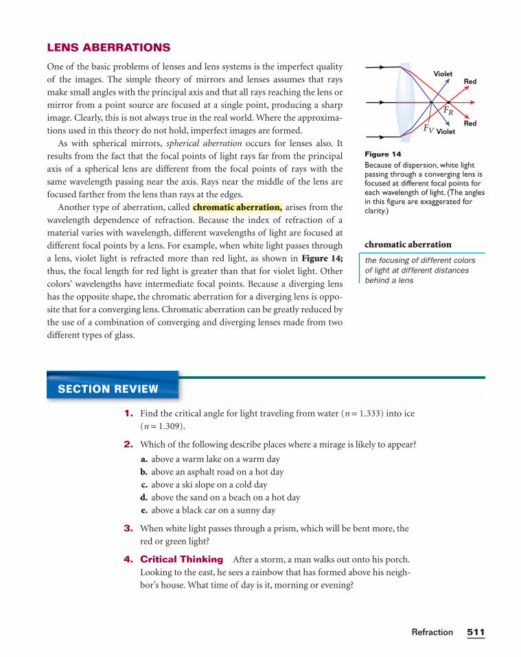
LENS ABERRATIONS
One of the basic problems of lenses and lens systems is the imperfect quality
of the images. The simple theory of mirrors and lenses assumes that rays
make small angles with the principal axis and that all rays reaching the lens or
mirror from a point source are focused at a single point, producing a sharp
image. Clearly, this is not always true in the real world. Where the approxima-
tions used in this theory do not hold, imperfect images are formed.
As with spherical mirrors, spherical aberration occurs for lenses also. It
results from the fact that the focal points of light rays far from the principal
axis of a spherical lens are different from the focal points of rays with the
same wavelength passing near the axis. Rays near the middle of the lens are
focused farther from the lens than rays at the edges.
Another type of aberration, called arises from the
wavelength dependence of refraction. Because the index of refraction of a
material varies with wavelength, different wavelengths of light are focused at
different focal points by a lens. For example, when white light passes through
a lens, violet light is refracted more than red light, as shown in Figure 14;thus, the focal length for red light is greater than that for violet light. Other
colors’ wavelengths have intermediate focal points. Because a diverging lens
has the opposite shape, the chromatic aberration for a diverging lens is oppo-
site that for a converging lens. Chromatic aberration can be greatly reduced by
the use of a combination of converging and diverging lenses made from two
different types of glass.
chromatic aberration,
511Refraction
SECTION REVIEW
1. Find the critical angle for light traveling from water (n = 1.333) into ice
(n = 1.309).
2. Which of the following describe places where a mirage is likely to appear?
a. above a warm lake on a warm day
b. above an asphalt road on a hot day
c. above a ski slope on a cold day
d. above the sand on a beach on a hot day
e. above a black car on a sunny day
3. When white light passes through a prism, which will be bent more, the
red or green light?
4. Critical Thinking After a storm, a man walks out onto his porch.
Looking to the east, he sees a rainbow that has formed above his neigh-
bor’s house. What time of day is it, morning or evening?
Red
Red
Violet
VioletFV
FR
Figure 14Because of dispersion, white lightpassing through a converging lens isfocused at different focal points foreach wavelength of light. (The anglesin this figure are exaggerated forclarity.)
chromatic aberration
the focusing of different colors of light at different distancesbehind a lens
512512
Optometrist
The job of an optometrist is to correctimperfect vision using optical devicessuch as eyeglasses or contact lenses.Optometrists also treat diseases of theeye such as glaucoma. To learn moreabout optometry as a career, read theinterview with Dewey Handy, O.D.
How did you decide to become an optometrist?For a while, I didn’t know what career I was going tochoose. In high school, I had a great love for geometryand an interest in science and anatomy. In college, Iwas looking for a challenge, so I ended up majoring inphysics—almost by accident.
In college, I decided to apply my abilities in science todirectly help people. I wasn’t excited about den-tistry or general medicine, but I was looking forsomething in a health career that would allowme to use physics.
What education is required to becomean optometrist?
I have a bachelor of science in physics, and Iattended optometry school for four years.
What sort of work does anoptometrist do?
After taking a complete eyeand medical history, thedoctor may use prismsand/or lenses to determinethe proper prescription forthe patient. Then, a seriesof neurological, health,and binocular vision testsare done. After the his-tory and data have beencollected, a diagnosis andtreatment plan are devel-oped. This treatment mayinclude glasses, contact lenses, low-vision aids, vision training, or med-ication for treatment of eye disease.
What do you enjoy most about your job?I like the problem-solving nature of the work,
putting the data together to come up withsolutions.We read the problem, compiledata, develop a formula, and solve the prob-lem—just as in physics, but with peopleinstead of abstract problems. I also like helping people.
What advice do you have for studentswho are interested in optometry?
You definitely need to have agood background in basic sci-ence: chemistry, biology, andphysics. Even if you don’t majorin science, you need to have agood grasp of it by the timeyou get to optometry school.
Being well rounded will helpyou get into optometryschool—and get out, too.You have to be comfort-able doing the science, but
you also have to be com-fortable dealing with people.
PHYSICS
CAREERS
Chapter 14
Dr. Dewey Handy uses optical devices to testthe vision of a patient.
KEY IDEAS
Section 1 Refraction• According to Snell’s law, as a light ray travels from one medium into
another medium where its speed is different, the light ray will change
its direction unless it travels along the normal.
• When light passes from a medium with a smaller index of refraction to
one with a larger index of refraction, the ray bends toward the normal.
For the opposite situation, the ray bends away from the normal.
Section 2 Thin Lenses• The image produced by a converging lens is real and inverted when the object
is outside the focal point and virtual and upright when the object is inside the
focal point. Diverging lenses always produce upright, virtual images.
• The location of an image created by a lens can be found using either a ray
diagram or the thin-lens equation.
Section 3 Optical Phenomena• Total internal reflection can occur when light attempts to move from a
material with a higher index of refraction to one with a lower index of
refraction. If the angle of incidence of a ray is greater than the critical
angle, the ray is totally reflected at the boundary.
• Mirages and the visibility of the sun after it has physically set are natural phe-
nomena that can be attributed to refraction of light in Earth’s atmosphere.
KEY TERMS
refraction (p. 488)
index of refraction (p. 490)
lens (p. 494)
total internal reflection (p. 506)
critical angle (p. 506)
dispersion (p. 509)
chromatic aberration (p. 511)
HighlightsCHAPTER 14
513Refraction
Variable Symbols
Quantities Units
qi angle of incidence ° degrees
qr angle of refraction ° degrees
n index of refraction
p distance from object to lens m meters
q distance from image to lens m meters
h� image height m meters
h object height m meters
qc critical angle ° degrees
PROBLEM SOLVING
See Appendix D: Equations for a summary of the equationsintroduced in this chapter. Ifyou need more problem-solvingpractice, see Appendix I: Additional Problems.
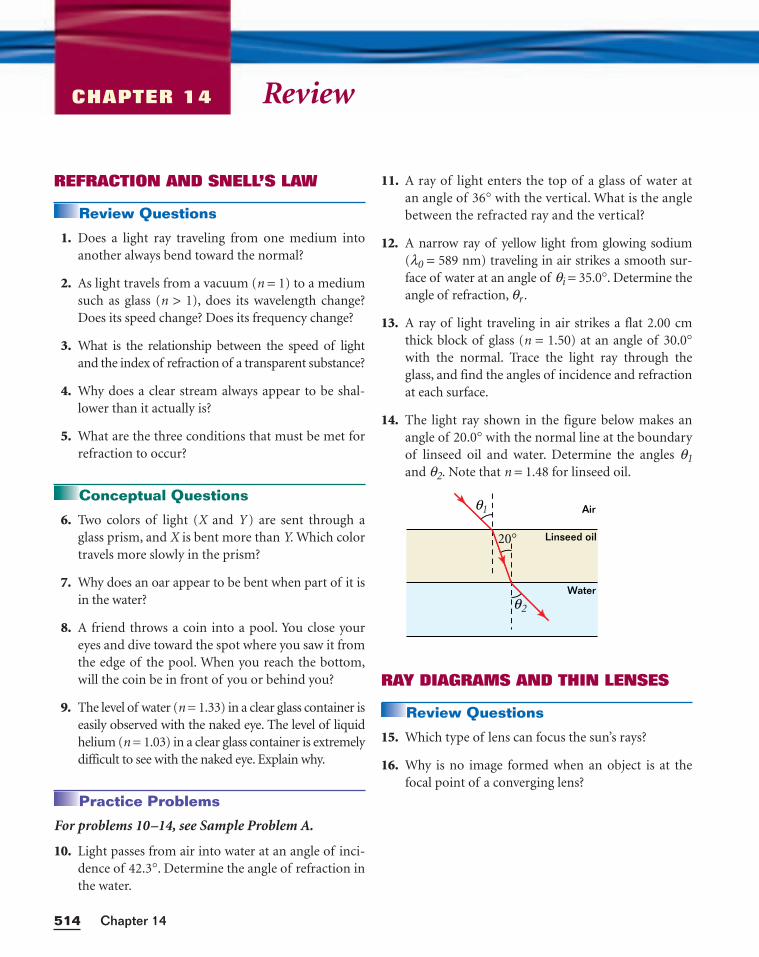
ReviewCHAPTER 14
REFRACTION AND SNELL’S LAW
Review Questions
1. Does a light ray traveling from one medium intoanother always bend toward the normal?
2. As light travels from a vacuum (n = 1) to a mediumsuch as glass (n > 1), does its wavelength change?Does its speed change? Does its frequency change?
3. What is the relationship between the speed of lightand the index of refraction of a transparent substance?
4. Why does a clear stream always appear to be shal-lower than it actually is?
5. What are the three conditions that must be met forrefraction to occur?
Conceptual Questions
6. Two colors of light (X and Y ) are sent through aglass prism, and X is bent more than Y. Which colortravels more slowly in the prism?
7. Why does an oar appear to be bent when part of it isin the water?
8. A friend throws a coin into a pool. You close youreyes and dive toward the spot where you saw it fromthe edge of the pool. When you reach the bottom,will the coin be in front of you or behind you?
9. The level of water (n = 1.33) in a clear glass container iseasily observed with the naked eye. The level of liquidhelium (n = 1.03) in a clear glass container is extremelydifficult to see with the naked eye. Explain why.
Practice Problems
For problems 10–14, see Sample Problem A.
10. Light passes from air into water at an angle of inci-dence of 42.3°. Determine the angle of refraction inthe water.
11. A ray of light enters the top of a glass of water atan angle of 36° with the vertical. What is the anglebetween the refracted ray and the vertical?
12. A narrow ray of yellow light from glowing sodium(l0 = 589 nm) traveling in air strikes a smooth sur-face of water at an angle of qi = 35.0°. Determine theangle of refraction, qr .
13. A ray of light traveling in air strikes a flat 2.00 cmthick block of glass (n = 1.50) at an angle of 30.0°with the normal. Trace the light ray through theglass, and find the angles of incidence and refractionat each surface.
14. The light ray shown in the figure below makes anangle of 20.0° with the normal line at the boundaryof linseed oil and water. Determine the angles q1and q2. Note that n = 1.48 for linseed oil.
RAY DIAGRAMS AND THIN LENSES
Review Questions
15. Which type of lens can focus the sun’s rays?
16. Why is no image formed when an object is at thefocal point of a converging lens?
Linseed oil
Water
20°
θ1
θ2
Air
Chapter 14514
17. Consider the image formed by a thin converginglens. Under what conditions will the image be
a. inverted?b. upright?c. real?d. virtual?e. larger than the object?f. smaller than the object?
18. Repeat a–f of item 17 for a thin diverging lens.
19. Explain this statement: The focal point of a con-verging lens is the location of an image of a pointobject at infinity. Based on this statement, can youthink of a quick method for determining the focallength of a positive lens?
Conceptual Questions
20. If a glass converging lens is submerged in water, willits focal length be longer or shorter than when thelens is in air?
21. In order to get an upright image, slides must beplaced upside down in a slide projector. What typeof lens must the slide projector have? Is the slideinside or outside the focal point of the lens?
22. If there are two converging lenses in a compoundmicroscope, why is the image still inverted?
23. In a Jules Verne novel, a piece of ice is shaped intothe form of a magnifying lens to focus sunlight andthereby start a fire. Is this possible?
Practice Problems
For problems 24–26, see Sample Problem B.
24. An object is placed in front of a diverging lens witha focal length of 20.0 cm. For each object distance,find the image distance and the magnification.Describe each image.
a. 40.0 cmb. 20.0 cmc. 10.0 cm
25. A person looks at a gem using a converging lenswith a focal length of 12.5 cm. The lens forms a vir-tual image 30.0 cm from the lens. Determine themagnification. Is the image upright or inverted?
26. An object is placed in front of a converging lenswith a focal length of 20.0 cm. For each object dis-tance, find the image distance and the magnifica-tion. Describe each image.
a. 40.0 cmb. 10.0 cm
TOTAL INTERNAL REFLECTION,ATMOSPHERIC REFRACTION, ANDABERRATIONS
Review Questions
27. Is it possible to have total internal reflection forlight incident from air on water? Explain.
28. What are the conditions necessary for the occur-rence of a mirage?
29. On a hot day, what is it that we are seeing when weobserve a “water on the road” mirage?
30. Why does the arc of a rainbow appear with red col-ors on top and violet colors on the bottom?
31. What type of aberration is involved in each of thefollowing situations?
a. The edges of the image appear reddish.b. The central portion of the image cannot be
clearly focused.c. The outer portion of the image cannot be
clearly focused.d. The central portion of the image is enlarged
relative to the outer portions.
Conceptual Questions
32. A laser beam passing through a nonhomogeneoussugar solution follows a curved path. Explain.
33. On a warm day, the image of a boat floating on coldwater appears above the boat. Explain.
34. Explain why a mirror cannot give rise to chromaticaberration.
35. Why does a diamond show flashes of color whenobserved under ordinary white light?
515Refraction
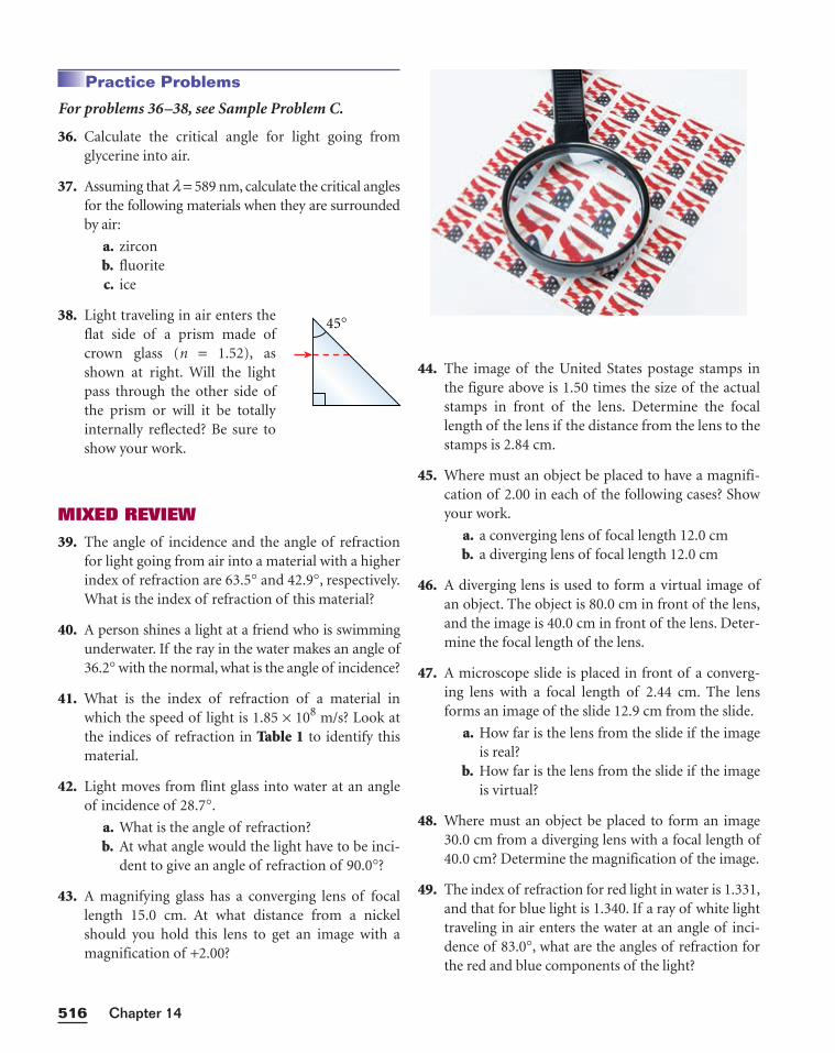
Practice Problems
For problems 36–38, see Sample Problem C.
36. Calculate the critical angle for light going fromglycerine into air.
37. Assuming that l = 589 nm, calculate the critical anglesfor the following materials when they are surroundedby air:
a. zirconb. fluoritec. ice
38. Light traveling in air enters theflat side of a prism made ofcrown glass (n = 1.52), asshown at right. Will the lightpass through the other side ofthe prism or will it be totallyinternally reflected? Be sure toshow your work.
MIXED REVIEW
39. The angle of incidence and the angle of refractionfor light going from air into a material with a higherindex of refraction are 63.5° and 42.9°, respectively.What is the index of refraction of this material?
40. A person shines a light at a friend who is swimmingunderwater. If the ray in the water makes an angle of36.2° with the normal, what is the angle of incidence?
41. What is the index of refraction of a material inwhich the speed of light is 1.85 × 10⁸ m/s? Look atthe indices of refraction in Table 1 to identify thismaterial.
42. Light moves from flint glass into water at an angleof incidence of 28.7°.
a. What is the angle of refraction?b. At what angle would the light have to be inci-
dent to give an angle of refraction of 90.0°?
43. A magnifying glass has a converging lens of focallength 15.0 cm. At what distance from a nickelshould you hold this lens to get an image with amagnification of +2.00?
44. The image of the United States postage stamps inthe figure above is 1.50 times the size of the actualstamps in front of the lens. Determine the focallength of the lens if the distance from the lens to thestamps is 2.84 cm.
45. Where must an object be placed to have a magnifi-cation of 2.00 in each of the following cases? Showyour work.
a. a converging lens of focal length 12.0 cmb. a diverging lens of focal length 12.0 cm
46. A diverging lens is used to form a virtual image ofan object. The object is 80.0 cm in front of the lens,and the image is 40.0 cm in front of the lens. Deter-mine the focal length of the lens.
47. A microscope slide is placed in front of a converg-ing lens with a focal length of 2.44 cm. The lensforms an image of the slide 12.9 cm from the slide.
a. How far is the lens from the slide if the imageis real?
b. How far is the lens from the slide if the imageis virtual?
48. Where must an object be placed to form an image30.0 cm from a diverging lens with a focal length of40.0 cm? Determine the magnification of the image.
49. The index of refraction for red light in water is 1.331,and that for blue light is 1.340. If a ray of white lighttraveling in air enters the water at an angle of inci-dence of 83.0°, what are the angles of refraction forthe red and blue components of the light?
Chapter 14516
45°
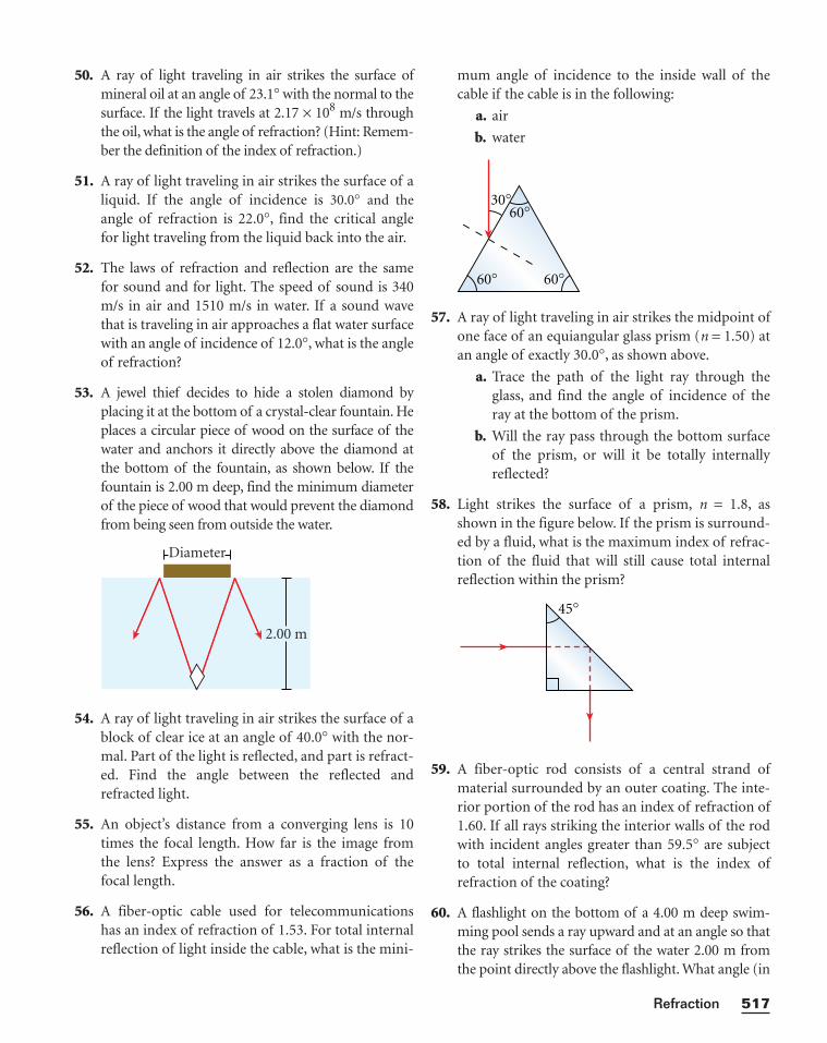
50. A ray of light traveling in air strikes the surface ofmineral oil at an angle of 23.1° with the normal to thesurface. If the light travels at 2.17 × 10⁸ m/s throughthe oil, what is the angle of refraction? (Hint: Remem-ber the definition of the index of refraction.)
51. A ray of light traveling in air strikes the surface of aliquid. If the angle of incidence is 30.0° and theangle of refraction is 22.0°, find the critical anglefor light traveling from the liquid back into the air.
52. The laws of refraction and reflection are the samefor sound and for light. The speed of sound is 340m/s in air and 1510 m/s in water. If a sound wavethat is traveling in air approaches a flat water surfacewith an angle of incidence of 12.0°, what is the angleof refraction?
53. A jewel thief decides to hide a stolen diamond byplacing it at the bottom of a crystal-clear fountain. Heplaces a circular piece of wood on the surface of thewater and anchors it directly above the diamond atthe bottom of the fountain, as shown below. If thefountain is 2.00 m deep, find the minimum diameterof the piece of wood that would prevent the diamondfrom being seen from outside the water.
54. A ray of light traveling in air strikes the surface of ablock of clear ice at an angle of 40.0° with the nor-mal. Part of the light is reflected, and part is refract-ed. Find the angle between the reflected andrefracted light.
55. An object’s distance from a converging lens is 10times the focal length. How far is the image fromthe lens? Express the answer as a fraction of thefocal length.
56. A fiber-optic cable used for telecommunicationshas an index of refraction of 1.53. For total internalreflection of light inside the cable, what is the mini-
Diameter
2.00 m
mum angle of incidence to the inside wall of thecable if the cable is in the following:
a. air
b. water
57. A ray of light traveling in air strikes the midpoint ofone face of an equiangular glass prism (n = 1.50) atan angle of exactly 30.0°, as shown above.
a. Trace the path of the light ray through theglass, and find the angle of incidence of theray at the bottom of the prism.
b. Will the ray pass through the bottom surfaceof the prism, or will it be totally internallyreflected?
58. Light strikes the surface of a prism, n = 1.8, asshown in the figure below. If the prism is surround-ed by a fluid, what is the maximum index of refrac-tion of the fluid that will still cause total internalreflection within the prism?
59. A fiber-optic rod consists of a central strand ofmaterial surrounded by an outer coating. The inte-rior portion of the rod has an index of refraction of1.60. If all rays striking the interior walls of the rodwith incident angles greater than 59.5° are subjectto total internal reflection, what is the index ofrefraction of the coating?
60. A flashlight on the bottom of a 4.00 m deep swim-ming pool sends a ray upward and at an angle so thatthe ray strikes the surface of the water 2.00 m fromthe point directly above the flashlight. What angle (in
45°
60°
60°60°
30°
517Refraction
air) does the emerging ray make with the water’s sur-face? (Hint: To determine the angle of incidence,consider the right triangle formed by the light ray, thepool bottom, and the imaginary line straight downfrom where the ray strikes the surface of the water.)
61. A submarine is 325 m horizontally out from theshore and 115 m beneath the surface of the water. Alaser beam is sent from the submarine so that itstrikes the surface of the water at a point 205 m fromthe shore. If the beam strikes the top of a buildingstanding directly at the water’s edge, find the height ofthe building. (Hint: To determine the angle of inci-dence, consider the right triangle formed by the lightbeam, the horizontal line drawn at the depth of the
submarine, and the imaginary line straight downfrom where the beam strikes the surface of the water.)
62. A laser beam traveling in air strikes the midpoint ofone end of a slab of material as shown in the figurebelow. The index of refraction of the slab is 1.48.Determine the number of internal reflections of thelaser beam before it finally emerges from the oppo-site end of the slab.
42.0 cm
3.1 mmn = 1.4850.0°
Chapter 14518
1. Interview an optometrist, optician, or ophthalmol-
ogist. Find out what equipment and tools each uses.
What kinds of eye problems is each able to correct?
What training is necessary for each career?
2. Obtain permission to use a microscope and slides
from your school’s biology teacher. Identify the opti-
cal components (lenses, mirror, object, and light
source) and knobs. Find out how they function at dif-
ferent magnifications and what adjustments must be
made to obtain a clear image. Sketch a ray diagram for
the microscope’s image formation. Estimate the size
of the images you see, and calculate the approximate
size of the actual cells or microorganisms you
observe. How closely do your estimates match the
magnification indicated on the microscope?
3. Construct your own telescope with mailing tubes
(one small enough to slide inside the other), two
lenses, cardboard disks for mounting the lenses,
glue, and masking tape. Test your instrument at
night. Try to combine different lenses and explore
ways to improve your telescope’s performance. Keep
records of your results to make a brochure docu-
menting the development of your telescope.
4. Research how phone, television, and radio signals
are transmitted over long distances through fiber-
optic devices. Obtain information from companies
that provide telephone or cable television service.
What materials are fiber-optic cables made of?
What are their most important properties? Are
there limits on the kind of light that travels in these
cables? What are the advantages of fiber-optic tech-
nology over broadcast transmission? Produce a
brochure or informational video to explain this
technology to consumers.
5. When the Indian physicist Venkata Raman first
saw the Mediterranean Sea, he proposed that its
blue color was due to the structure of water mol-
ecules rather than to the scattering of light from
suspended particles. Later, he won the Nobel Prize
for work relating to the implications of this
hypothesis. Research Raman’s life and work. Find
out about his background and the challenges and
opportunities he met on his way to becoming a
physicist. Create a presentation about him in the
form of a report, poster, short video, or computer
presentation.
Alternative Assessment
63. A nature photographer is using a camera that has alens with a focal length of 4.80 cm. The photogra-pher is taking pictures of ancient trees in a forestand wants the lens to be focused on a very old treethat is 10.0 m away.
a. How far must the lens be from the film in orderfor the resulting picture to be clearly focused?
b. How much would the lens have to be movedto take a picture of another tree that is only1.75 m away?
64. The distance from the front to the back of your eyeis approximately 1.90 cm. If you can see a clearimage of a book when it is 35.0 cm from your eye,what is the focal length of the lens/cornea system?
65. Suppose you look out the window and see yourfriend, who is standing 15.0 m away. To what focallength must your eye muscles adjust the lens ofyour eye so that you may see your friend clearly?Remember that the distance from the front to theback of your eye is about 1.90 cm.
519Refraction
In this graphing calculator activity, you will enter
the angle of incidence and will view a graph of the
index of refraction versus the angle of refraction.
You can use this graph to better understand the
relationship between the index of refraction and the
angle of refraction.
Visit go.hrw.com and enter the keyword
HF6REFX to find this graphing calculator activity.
Refer to Appendix B for instructions on download-
ing the program for this activity.
Snell’s LawWhat happens to a light ray that passes from air into
a medium whose index of refraction differs from
that of air? Snell’s law, as you learned earlier in this
chapter, describes the relationship between the
angle of refraction and the index of refraction.
ni sin q i = nr sin q r
In this equation, ni is the index of refraction of the
medium of the incident light ray, and qi is the angle
of incidence; nr is the index of refraction of the
medium of the refracted light, and qr is the angle of
refraction.
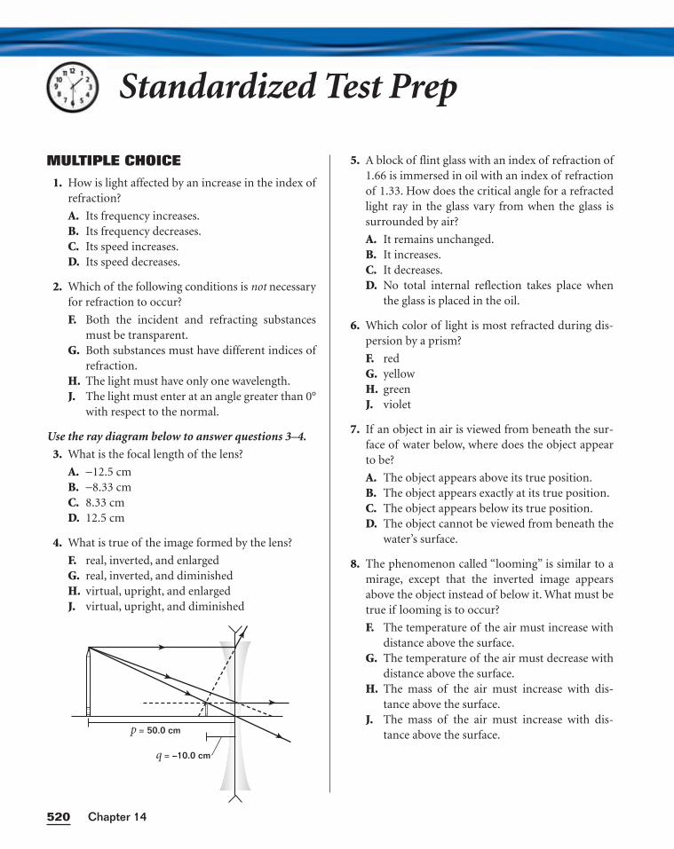
Standardized Test Prep
MULTIPLE CHOICE
1. How is light affected by an increase in the index ofrefraction?
A. Its frequency increases.B. Its frequency decreases.C. Its speed increases.D. Its speed decreases.
2. Which of the following conditions is not necessaryfor refraction to occur?
F. Both the incident and refracting substancesmust be transparent.
G. Both substances must have different indices ofrefraction.
H. The light must have only one wavelength.J. The light must enter at an angle greater than 0°
with respect to the normal.
Use the ray diagram below to answer questions 3–4.
3. What is the focal length of the lens?
A. −12.5 cmB. −8.33 cmC. 8.33 cmD. 12.5 cm
4. What is true of the image formed by the lens?
F. real, inverted, and enlargedG. real, inverted, and diminishedH. virtual, upright, and enlargedJ. virtual, upright, and diminished
p = 50.0 cm
q = –10.0 cm
5. A block of flint glass with an index of refraction of1.66 is immersed in oil with an index of refractionof 1.33. How does the critical angle for a refractedlight ray in the glass vary from when the glass issurrounded by air?
A. It remains unchanged.B. It increases.C. It decreases.D. No total internal reflection takes place when
the glass is placed in the oil.
6. Which color of light is most refracted during dis-persion by a prism?
F. redG. yellowH. greenJ. violet
7. If an object in air is viewed from beneath the sur-face of water below, where does the object appearto be?
A. The object appears above its true position.B. The object appears exactly at its true position.C. The object appears below its true position.D. The object cannot be viewed from beneath the
water’s surface.
8. The phenomenon called “looming” is similar to amirage, except that the inverted image appearsabove the object instead of below it. What must betrue if looming is to occur?
F. The temperature of the air must increase withdistance above the surface.
G. The temperature of the air must decrease withdistance above the surface.
H. The mass of the air must increase with dis-tance above the surface.
J. The mass of the air must increase with dis-tance above the surface.
Chapter 14520
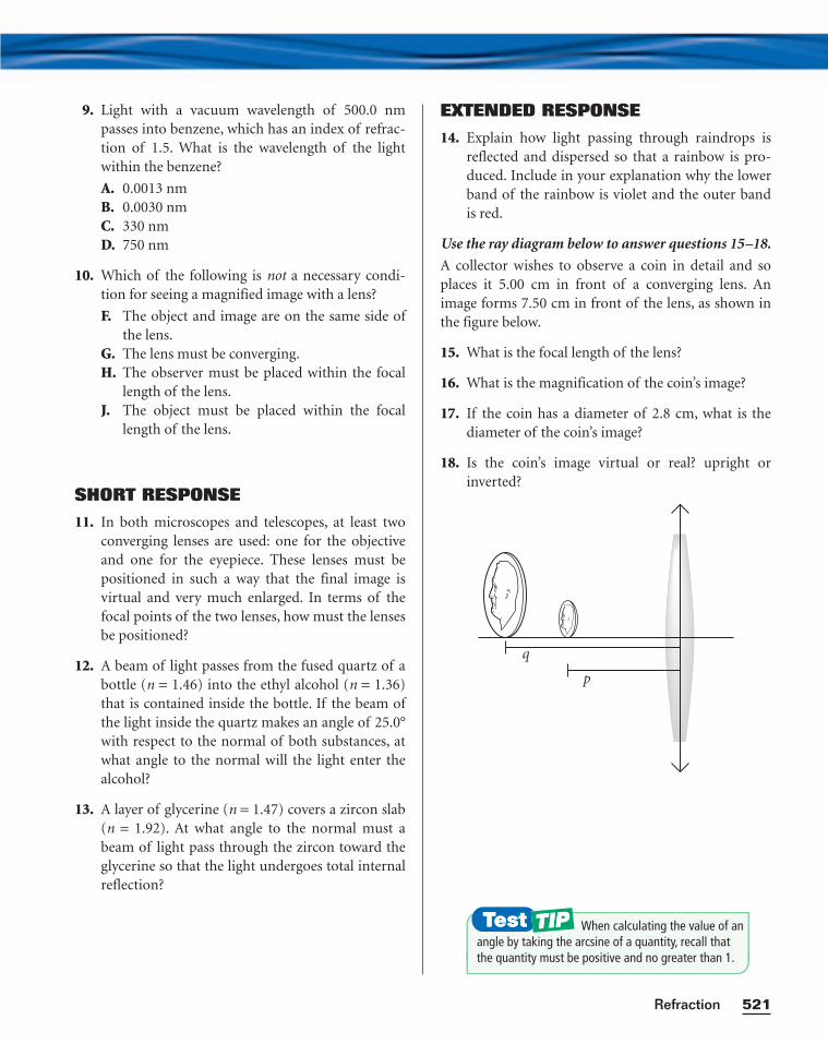
9. Light with a vacuum wavelength of 500.0 nmpasses into benzene, which has an index of refrac-tion of 1.5. What is the wavelength of the lightwithin the benzene?
A. 0.0013 nmB. 0.0030 nmC. 330 nmD. 750 nm
10. Which of the following is not a necessary condi-tion for seeing a magnified image with a lens?
F. The object and image are on the same side ofthe lens.
G. The lens must be converging.H. The observer must be placed within the focal
length of the lens.J. The object must be placed within the focal
length of the lens.
SHORT RESPONSE
11. In both microscopes and telescopes, at least twoconverging lenses are used: one for the objectiveand one for the eyepiece. These lenses must bepositioned in such a way that the final image isvirtual and very much enlarged. In terms of thefocal points of the two lenses, how must the lensesbe positioned?
12. A beam of light passes from the fused quartz of abottle (n = 1.46) into the ethyl alcohol (n = 1.36)that is contained inside the bottle. If the beam ofthe light inside the quartz makes an angle of 25.0°with respect to the normal of both substances, atwhat angle to the normal will the light enter thealcohol?
13. A layer of glycerine (n = 1.47) covers a zircon slab(n = 1.92). At what angle to the normal must abeam of light pass through the zircon toward theglycerine so that the light undergoes total internalreflection?
EXTENDED RESPONSE
14. Explain how light passing through raindrops isreflected and dispersed so that a rainbow is pro-duced. Include in your explanation why the lowerband of the rainbow is violet and the outer band is red.
Use the ray diagram below to answer questions 15–18.
A collector wishes to observe a coin in detail and soplaces it 5.00 cm in front of a converging lens. Animage forms 7.50 cm in front of the lens, as shown inthe figure below.
15. What is the focal length of the lens?
16. What is the magnification of the coin’s image?
17. If the coin has a diameter of 2.8 cm, what is thediameter of the coin’s image?
18. Is the coin’s image virtual or real? upright orinverted?
q
p
521Refraction
When calculating the value of anangle by taking the arcsine of a quantity, recall thatthe quantity must be positive and no greater than 1.
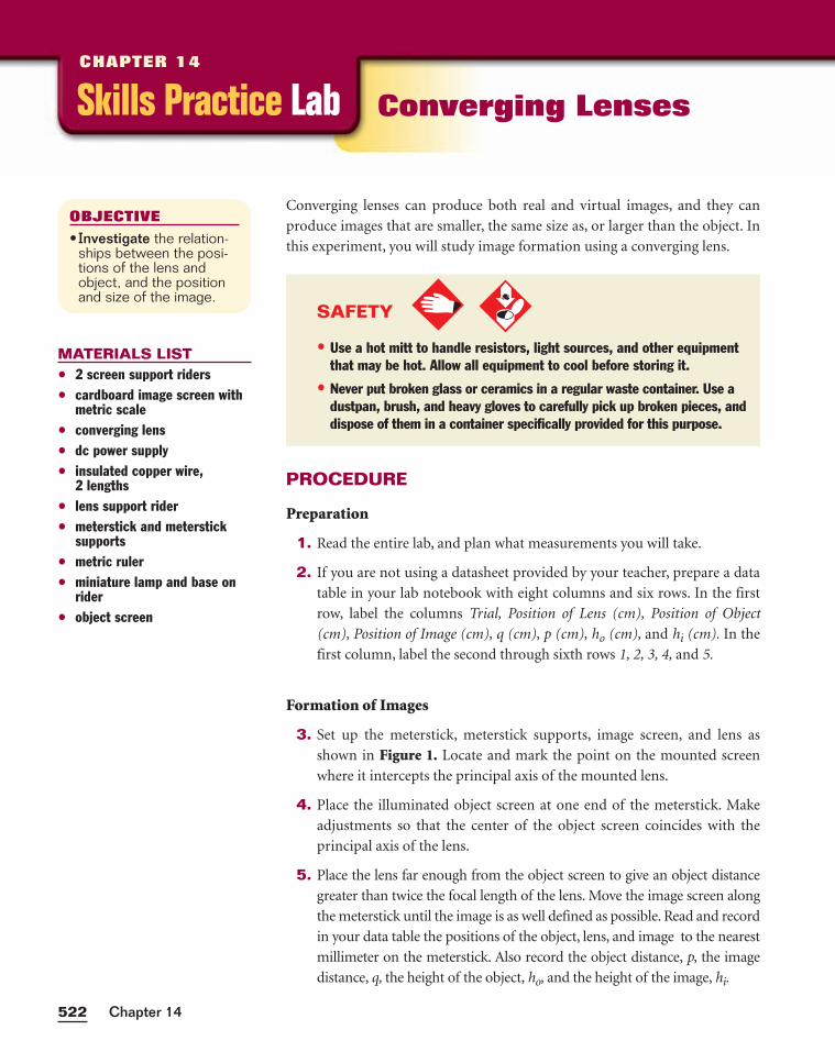
Chapter 14522
PROCEDURE
Preparation
1. Read the entire lab, and plan what measurements you will take.
2. If you are not using a datasheet provided by your teacher, prepare a data
table in your lab notebook with eight columns and six rows. In the first
row, label the columns Trial, Position of Lens (cm), Position of Object
(cm), Position of Image (cm), q (cm), p (cm), ho (cm), and hi (cm). In the
first column, label the second through sixth rows 1, 2, 3, 4, and 5.
Formation of Images
3. Set up the meterstick, meterstick supports, image screen, and lens as
shown in Figure 1. Locate and mark the point on the mounted screen
where it intercepts the principal axis of the mounted lens.
4. Place the illuminated object screen at one end of the meterstick. Make
adjustments so that the center of the object screen coincides with the
principal axis of the lens.
5. Place the lens far enough from the object screen to give an object distance
greater than twice the focal length of the lens. Move the image screen along
the meterstick until the image is as well defined as possible. Read and record
in your data table the positions of the object, lens, and image to the nearest
millimeter on the meterstick. Also record the object distance, p, the image
distance, q, the height of the object, ho, and the height of the image, hi.
Converging lenses can produce both real and virtual images, and they can
produce images that are smaller, the same size as, or larger than the object. In
this experiment, you will study image formation using a converging lens.
OBJECTIVE
• Investigate the relation-ships between the posi-tions of the lens andobject, and the positionand size of the image.
MATERIALS LIST• 2 screen support riders• cardboard image screen with
metric scale• converging lens• dc power supply• insulated copper wire,
2 lengths• lens support rider• meterstick and meterstick
supports• metric ruler• miniature lamp and base on
rider• object screen
Skills Practice LabCHAPTER 14
Converging Lenses
SAFETY
• Use a hot mitt to handle resistors, light sources, and other equipmentthat may be hot. Allow all equipment to cool before storing it.
• Never put broken glass or ceramics in a regular waste container. Use adustpan, brush, and heavy gloves to carefully pick up broken pieces, anddispose of them in a container specifically provided for this purpose.
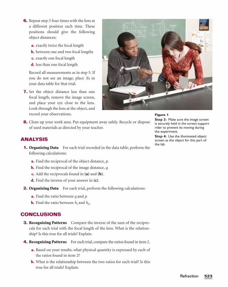
523Refraction
6. Repeat step 5 four times with the lens at
a different position each time. These
positions should give the following
object distances:
a. exactly twice the focal length
b. between one and two focal lengths
c. exactly one focal length
d. less than one focal length
Record all measurements as in step 5. If
you do not see an image, place Xs in
your data table for that trial.
7. Set the object distance less than one
focal length, remove the image screen,
and place your eye close to the lens.
Look through the lens at the object, and
record your observations.
8. Clean up your work area. Put equipment away safely. Recycle or dispose
of used materials as directed by your teacher.
ANALYSIS
1. Organizing Data For each trial recorded in the data table, perform the
following calculations:
a. Find the reciprocal of the object distance, p.
b. Find the reciprocal of the image distance, q.
c. Add the reciprocals found in (a) and (b).
d. Find the inverse of your answer in (c).
2. Organizing Data For each trial, perform the following calculations:
a. Find the ratio between q and p.
b. Find the ratio between hi and ho.
CONCLUSIONS
3. Recognizing Patterns Compare the inverse of the sum of the recipro-
cals for each trial with the focal length of the lens. What is the relation-
ship? Is this true for all trials? Explain.
4. Recognizing Patterns For each trial, compare the ratios found in item 2.
a. Based on your results, what physical quantity is expressed by each of
the ratios found in item 2?
b. What is the relationship between the two ratios for each trial? Is this
true for all trials? Explain.
Figure 1Step 3: Make sure the image screen is securely held in the screen supportrider to prevent its moving during the experiment.Step 4: Use the illuminated objectscreen as the object for this part of the lab.
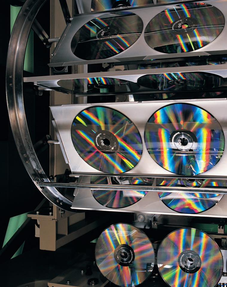
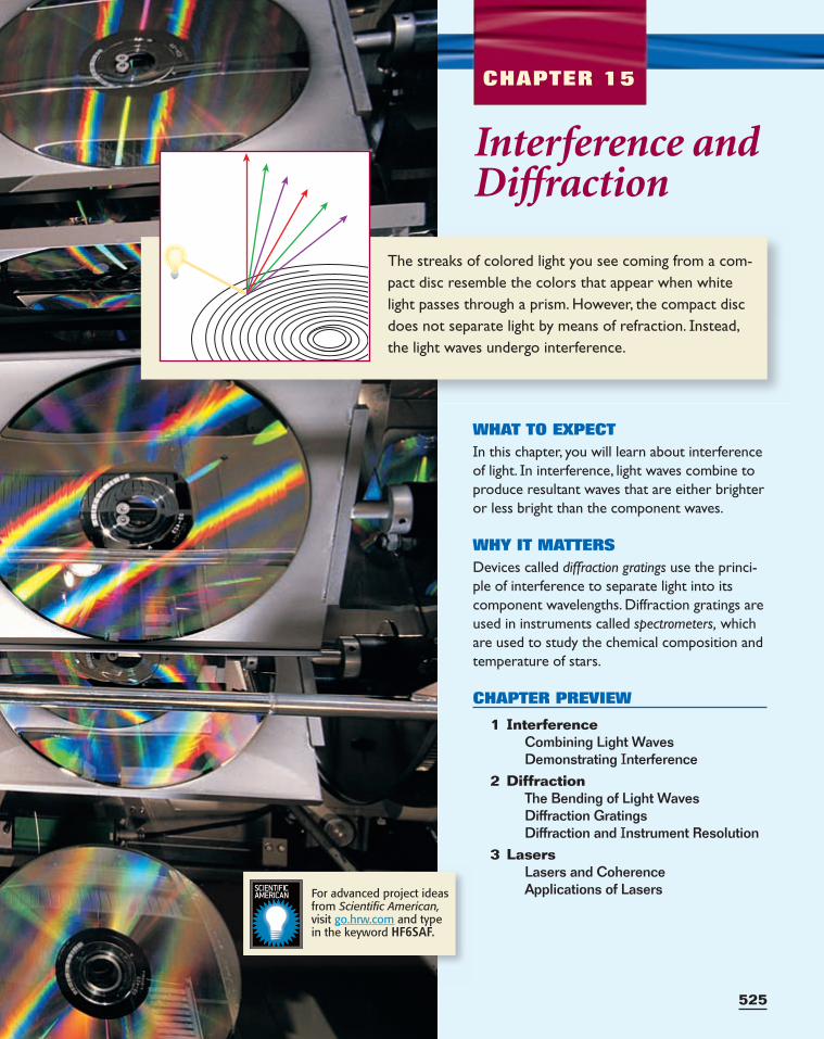
525
The streaks of colored light you see coming from a com-pact disc resemble the colors that appear when whitelight passes through a prism. However, the compact discdoes not separate light by means of refraction. Instead,the light waves undergo interference.
CHAPTER 15
Interference andDiffraction
WHAT TO EXPECTIn this chapter, you will learn about interferenceof light. In interference, light waves combine toproduce resultant waves that are either brighteror less bright than the component waves.
WHY IT MATTERSDevices called diffraction gratings use the princi-ple of interference to separate light into itscomponent wavelengths. Diffraction gratings areused in instruments called spectrometers, whichare used to study the chemical composition andtemperature of stars.
CHAPTER PREVIEW
1 InterferenceCombining Light WavesDemonstrating Interference
2 DiffractionThe Bending of Light WavesDiffraction GratingsDiffraction and Instrument Resolution
3 LasersLasers and CoherenceApplications of LasersFor advanced project ideas
from Scientific American,visit go.hrw.com and type in the keyword HF6SAF.
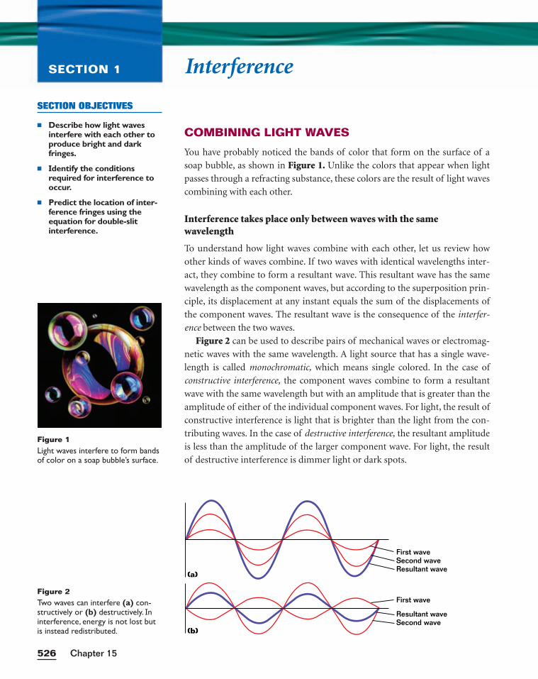
InterferenceSECTION 1
COMBINING LIGHT WAVES
You have probably noticed the bands of color that form on the surface of a
soap bubble, as shown in Figure 1. Unlike the colors that appear when light
passes through a refracting substance, these colors are the result of light waves
combining with each other.
Interference takes place only between waves with the samewavelength
To understand how light waves combine with each other, let us review how
other kinds of waves combine. If two waves with identical wavelengths inter-
act, they combine to form a resultant wave. This resultant wave has the same
wavelength as the component waves, but according to the superposition prin-
ciple, its displacement at any instant equals the sum of the displacements of
the component waves. The resultant wave is the consequence of the interfer-
ence between the two waves.
Figure 2 can be used to describe pairs of mechanical waves or electromag-
netic waves with the same wavelength. A light source that has a single wave-
length is called monochromatic, which means single colored. In the case of
constructive interference, the component waves combine to form a resultant
wave with the same wavelength but with an amplitude that is greater than the
amplitude of either of the individual component waves. For light, the result of
constructive interference is light that is brighter than the light from the con-
tributing waves. In the case of destructive interference, the resultant amplitude
is less than the amplitude of the larger component wave. For light, the result
of destructive interference is dimmer light or dark spots.
Chapter 15526
SECTION OBJECTIVES
■ Describe how light wavesinterfere with each other toproduce bright and darkfringes.
■ Identify the conditionsrequired for interference tooccur.
■ Predict the location of inter-ference fringes using theequation for double-slit interference.
First waveSecond waveResultant wave
(a)
(b)
First wave
Resultant waveSecond wave
Figure 2Two waves can interfere (a) con-structively or (b) destructively. Ininterference, energy is not lost butis instead redistributed.
Figure 1Light waves interfere to form bandsof color on a soap bubble’s surface.
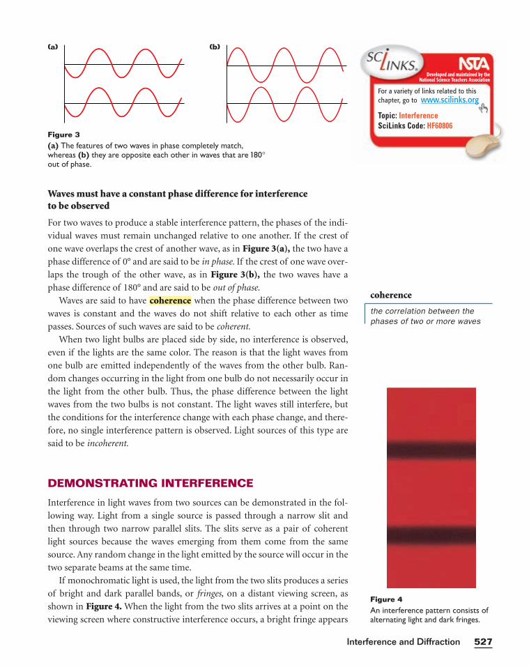
Waves must have a constant phase difference for interference to be observed
For two waves to produce a stable interference pattern, the phases of the indi-
vidual waves must remain unchanged relative to one another. If the crest of
one wave overlaps the crest of another wave, as in Figure 3(a), the two have a
phase difference of 0° and are said to be in phase. If the crest of one wave over-
laps the trough of the other wave, as in Figure 3(b), the two waves have a
phase difference of 180° and are said to be out of phase.
Waves are said to have when the phase difference between two
waves is constant and the waves do not shift relative to each other as time
passes. Sources of such waves are said to be coherent.
When two light bulbs are placed side by side, no interference is observed,
even if the lights are the same color. The reason is that the light waves from
one bulb are emitted independently of the waves from the other bulb. Ran-
dom changes occurring in the light from one bulb do not necessarily occur in
the light from the other bulb. Thus, the phase difference between the light
waves from the two bulbs is not constant. The light waves still interfere, but
the conditions for the interference change with each phase change, and there-
fore, no single interference pattern is observed. Light sources of this type are
said to be incoherent.
DEMONSTRATING INTERFERENCE
Interference in light waves from two sources can be demonstrated in the fol-
lowing way. Light from a single source is passed through a narrow slit and
then through two narrow parallel slits. The slits serve as a pair of coherent
light sources because the waves emerging from them come from the same
source. Any random change in the light emitted by the source will occur in the
two separate beams at the same time.
If monochromatic light is used, the light from the two slits produces a series
of bright and dark parallel bands, or fringes, on a distant viewing screen, as
shown in Figure 4. When the light from the two slits arrives at a point on the
viewing screen where constructive interference occurs, a bright fringe appears
coherence
527Interference and Diffraction
Figure 3(a) The features of two waves in phase completely match,whereas (b) they are opposite each other in waves that are 180°out of phase.
coherence
the correlation between thephases of two or more waves
(a) (b)
Figure 4An interference pattern consists ofalternating light and dark fringes.
Developed and maintained by theNational Science Teachers Association
For a variety of links related to thischapter, go to www.scilinks.org
Topic: InterferenceSciLinks Code: HF60806
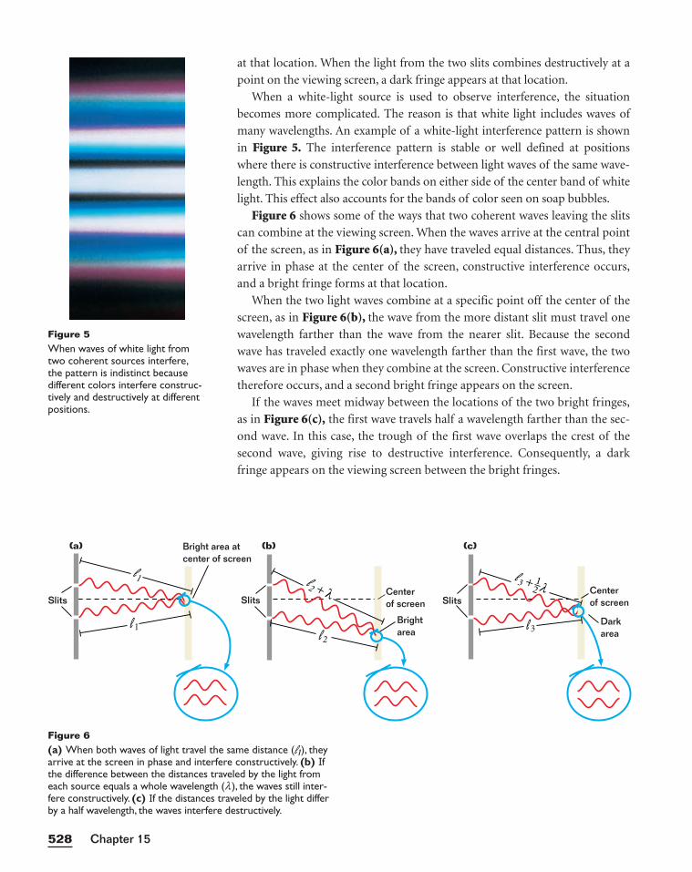
at that location. When the light from the two slits combines destructively at a
point on the viewing screen, a dark fringe appears at that location.
When a white-light source is used to observe interference, the situation
becomes more complicated. The reason is that white light includes waves of
many wavelengths. An example of a white-light interference pattern is shown
in Figure 5. The interference pattern is stable or well defined at positions
where there is constructive interference between light waves of the same wave-
length. This explains the color bands on either side of the center band of white
light. This effect also accounts for the bands of color seen on soap bubbles.
Figure 6 shows some of the ways that two coherent waves leaving the slits
can combine at the viewing screen. When the waves arrive at the central point
of the screen, as in Figure 6(a), they have traveled equal distances. Thus, they
arrive in phase at the center of the screen, constructive interference occurs,
and a bright fringe forms at that location.
When the two light waves combine at a specific point off the center of the
screen, as in Figure 6(b), the wave from the more distant slit must travel one
wavelength farther than the wave from the nearer slit. Because the second
wave has traveled exactly one wavelength farther than the first wave, the two
waves are in phase when they combine at the screen. Constructive interference
therefore occurs, and a second bright fringe appears on the screen.
If the waves meet midway between the locations of the two bright fringes,
as in Figure 6(c), the first wave travels half a wavelength farther than the sec-
ond wave. In this case, the trough of the first wave overlaps the crest of the
second wave, giving rise to destructive interference. Consequently, a dark
fringe appears on the viewing screen between the bright fringes.
Chapter 15528
Figure 5When waves of white light fromtwo coherent sources interfere,the pattern is indistinct because different colors interfere construc-tively and destructively at differentpositions.
Figure 6(a) When both waves of light travel the same distance (l1), theyarrive at the screen in phase and interfere constructively. (b) Ifthe difference between the distances traveled by the light fromeach source equals a whole wavelength (l), the waves still inter-fere constructively. (c) If the distances traveled by the light differby a half wavelength, the waves interfere destructively.
(a) (b) (c)
l1
l1
Slits
Bright area at center of screen
Slits
l2 + λ
l2
Centerof screen
Brightarea l3
SlitsCenterof screen
Darkarea
l3 + 12 λ
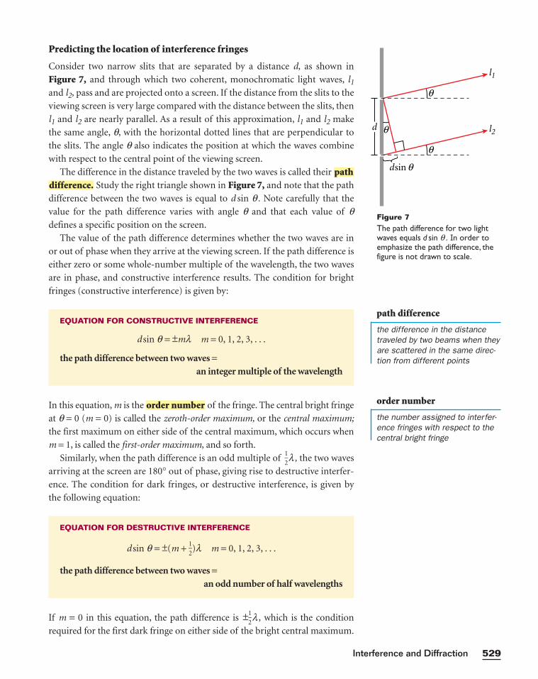
Predicting the location of interference fringes
Consider two narrow slits that are separated by a distance d, as shown in
Figure 7, and through which two coherent, monochromatic light waves, l1and l2, pass and are projected onto a screen. If the distance from the slits to the
viewing screen is very large compared with the distance between the slits, then
l1 and l2 are nearly parallel. As a result of this approximation, l1 and l2 make
the same angle, q, with the horizontal dotted lines that are perpendicular to
the slits. The angle q also indicates the position at which the waves combine
with respect to the central point of the viewing screen.
The difference in the distance traveled by the two waves is called their
Study the right triangle shown in Figure 7, and note that the path
difference between the two waves is equal to d sin q . Note carefully that the
value for the path difference varies with angle q and that each value of qdefines a specific position on the screen.
The value of the path difference determines whether the two waves are in
or out of phase when they arrive at the viewing screen. If the path difference is
either zero or some whole-number multiple of the wavelength, the two waves
are in phase, and constructive interference results. The condition for bright
fringes (constructive interference) is given by:
In this equation, m is the of the fringe. The central bright fringe
at q = 0 (m = 0) is called the zeroth-order maximum, or the central maximum;
the first maximum on either side of the central maximum, which occurs when
m = 1, is called the first-order maximum, and so forth.
Similarly, when the path difference is an odd multiple of 12
l , the two waves
arriving at the screen are 180° out of phase, giving rise to destructive interfer-
ence. The condition for dark fringes, or destructive interference, is given by
the following equation:
If m = 0 in this equation, the path difference is ±12
l , which is the condition
required for the first dark fringe on either side of the bright central maximum.
EQUATION FOR DESTRUCTIVE INTERFERENCE
d sin q = ±(m + 12
)l m = 0, 1, 2, 3, . . .
the path difference between two waves =an odd number of half wavelengths
order number
EQUATION FOR CONSTRUCTIVE INTERFERENCE
d sin q = ±ml m = 0, 1, 2, 3, . . .
the path difference between two waves =an integer multiple of the wavelength
difference.path
529Interference and Diffraction
l1
d l2
θ
θ
dsin θ
θ
Figure 7The path difference for two lightwaves equals d sin q . In order toemphasize the path difference, thefigure is not drawn to scale.
path difference
the difference in the distancetraveled by two beams when theyare scattered in the same direc-tion from different points
order number
the number assigned to interfer-ence fringes with respect to thecentral bright fringe
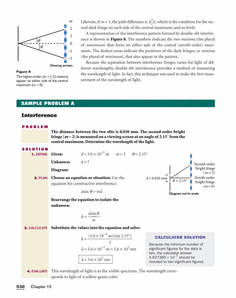
Likewise, if m = 1, the path difference is ±32
l , which is the condition for the sec-
ond dark fringe on each side of the central maximum, and so forth.
A representation of the interference pattern formed by double-slit interfer-
ence is shown in Figure 8. The numbers indicate the two maxima (the plural
of maximum) that form on either side of the central (zeroth-order) maxi-
mum. The darkest areas indicate the positions of the dark fringes, or minima
(the plural of minimum), that also appear in the pattern.
Because the separation between interference fringes varies for light of dif-
ferent wavelengths, double-slit interference provides a method of measuring
the wavelength of light. In fact, this technique was used to make the first meas-
urement of the wavelength of light.
Chapter 15530
m
2
1
–1
–2
0
Viewing screen
θθ
Figure 8The higher-order (m = 1, 2) maximaappear on either side of the centralmaximum (m = 0).
SAMPLE PROBLEM A
Interference
P R O B L E MThe distance between the two slits is 0.030 mm. The second-order brightfringe (m = 2) is measured on a viewing screen at an angle of 2.15° from thecentral maximum. Determine the wavelength of the light.
S O L U T I O NGiven: d = 3.0 × 10⁻⁵ m m = 2 q = 2.15°
Unknown: l = ?
Diagram:
Choose an equation or situation: Use the
equation for constructive interference.
d sin q = ml
Rearrange the equation to isolate the unknown:
l = d s
m
in q
Substitute the values into the equation and solve:
l =
l = 5.6 × 10⁻⁷ m = 5.6 × 10² nm
This wavelength of light is in the visible spectrum. The wavelength corre-
sponds to light of a yellow-green color.
l = 5.6 × 10² nm
(3.0 × 10⁻⁵ m)(sin 2.15°)
2
1. DEFINE
2. PLAN
3. CALCULATE
4. EVALUATE
CALCULATOR SOLUTION
Because the minimum number of significant figures for the data is two, the calculator answer 5.627366 × 10⁻⁷ should be rounded to two significant figures.
Zeroth-orderbright fringe
(m = 0)
Second-orderbright fringe
(m = 2)
d = 0.030 mm = 2.15°θ
Diagram not to scale
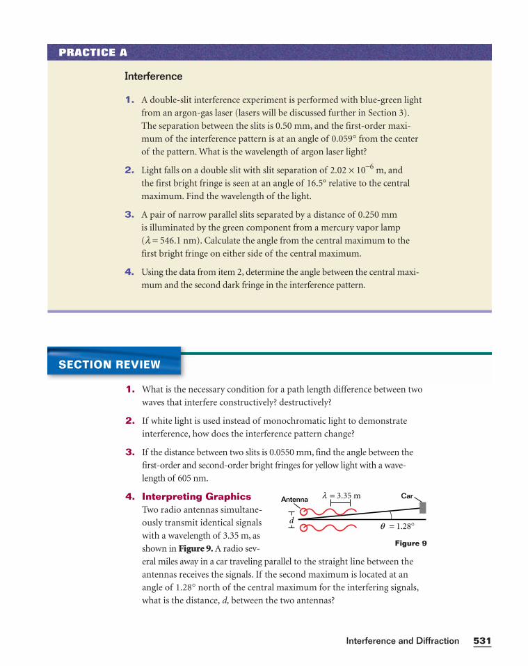
531Interference and Diffraction
PRACTICE A
Interference
1. A double-slit interference experiment is performed with blue-green light
from an argon-gas laser (lasers will be discussed further in Section 3).
The separation between the slits is 0.50 mm, and the first-order maxi-
mum of the interference pattern is at an angle of 0.059° from the center
of the pattern. What is the wavelength of argon laser light?
2. Light falls on a double slit with slit separation of 2.02 × 10⁻⁶ m, and
the first bright fringe is seen at an angle of 16.5° relative to the central
maximum. Find the wavelength of the light.
3. A pair of narrow parallel slits separated by a distance of 0.250 mm
is illuminated by the green component from a mercury vapor lamp
(l = 546.1 nm). Calculate the angle from the central maximum to the
first bright fringe on either side of the central maximum.
4. Using the data from item 2, determine the angle between the central maxi-
mum and the second dark fringe in the interference pattern.
SECTION REVIEW
1. What is the necessary condition for a path length difference between two
waves that interfere constructively? destructively?
2. If white light is used instead of monochromatic light to demonstrate
interference, how does the interference pattern change?
3. If the distance between two slits is 0.0550 mm, find the angle between the
first-order and second-order bright fringes for yellow light with a wave-
length of 605 nm.
4. Interpreting GraphicsTwo radio antennas simultane-
ously transmit identical signals
with a wavelength of 3.35 m, as
shown in Figure 9. A radio sev-
eral miles away in a car traveling parallel to the straight line between the
antennas receives the signals. If the second maximum is located at an
angle of 1.28° north of the central maximum for the interfering signals,
what is the distance, d, between the two antennas?
d= 1.28°θ
= 3.35 mλAntenna Car
Figure 9
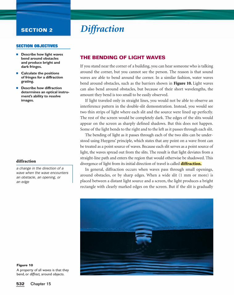
DiffractionSECTION 2
THE BENDING OF LIGHT WAVES
If you stand near the corner of a building, you can hear someone who is talking
around the corner, but you cannot see the person. The reason is that sound
waves are able to bend around the corner. In a similar fashion, water waves
bend around obstacles, such as the barriers shown in Figure 10. Light waves
can also bend around obstacles, but because of their short wavelengths, the
amount they bend is too small to be easily observed.
If light traveled only in straight lines, you would not be able to observe an
interference pattern in the double-slit demonstration. Instead, you would see
two thin strips of light where each slit and the source were lined up perfectly.
The rest of the screen would be completely dark. The edges of the slits would
appear on the screen as sharply defined shadows. But this does not happen.
Some of the light bends to the right and to the left as it passes through each slit.
The bending of light as it passes through each of the two slits can be under-
stood using Huygens’ principle, which states that any point on a wave front can
be treated as a point source of waves. Because each slit serves as a point source of
light, the waves spread out from the slits. The result is that light deviates from a
straight-line path and enters the region that would otherwise be shadowed. This
divergence of light from its initial direction of travel is called
In general, diffraction occurs when waves pass through small openings,
around obstacles, or by sharp edges. When a wide slit (1 mm or more) is
placed between a distant light source and a screen, the light produces a bright
rectangle with clearly marked edges on the screen. But if the slit is gradually
diffraction.
Chapter 15532
SECTION OBJECTIVES
■ Describe how light waves bend around obstacles and produce bright and dark fringes.
■ Calculate the positions of fringes for a diffractiongrating.
■ Describe how diffractiondetermines an optical instru-ment’s ability to resolveimages.
Figure 10A property of all waves is that theybend, or diffract, around objects.
diffraction
a change in the direction of awave when the wave encountersan obstacle, an opening, or an edge
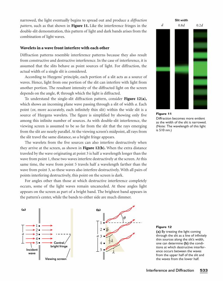
narrowed, the light eventually begins to spread out and produce a diffraction
pattern, such as that shown in Figure 11. Like the interference fringes in the
double-slit demonstration, this pattern of light and dark bands arises from the
combination of light waves.
Wavelets in a wave front interfere with each other
Diffraction patterns resemble interference patterns because they also result
from constructive and destructive interference. In the case of interference, it is
assumed that the slits behave as point sources of light. For diffraction, the
actual width of a single slit is considered.
According to Huygens’ principle, each portion of a slit acts as a source of
waves. Hence, light from one portion of the slit can interfere with light from
another portion. The resultant intensity of the diffracted light on the screen
depends on the angle, q, through which the light is diffracted.
To understand the single-slit diffraction pattern, consider Figure 12(a),which shows an incoming plane wave passing through a slit of width a. Each
point (or, more accurately, each infinitely thin slit) within the wide slit is a
source of Huygens wavelets. The figure is simplified by showing only five
among this infinite number of sources. As with double-slit interference, the
viewing screen is assumed to be so far from the slit that the rays emerging
from the slit are nearly parallel. At the viewing screen’s midpoint, all rays from
the slit travel the same distance, so a bright fringe appears.
The wavelets from the five sources can also interfere destructively when
they arrive at the screen, as shown in Figure 12(b). When the extra distance
traveled by the wave originating at point 3 is half a wavelength longer than the
wave from point 1, these two waves interfere destructively at the screen. At this
same time, the wave from point 5 travels half a wavelength farther than the
wave from point 3, so these waves also interfere destructively. With all pairs of
points interfering destructively, this point on the screen is dark.
For angles other than those at which destructive interference completely
occurs, some of the light waves remain uncanceled. At these angles light
appears on the screen as part of a bright band. The brightest band appears in
the pattern’s center, while the bands to either side are much dimmer.
533Interference and Diffraction
d 0.8d 0.2d
Slit width
Figure 11Diffraction becomes more evidentas the width of the slit is narrowed.(Note: The wavelength of this lightis 5 10 nm.)
Viewing screen
Centralbright fringe
Incidentwave
12345
a
(a)
a 3
2
1
5
412
(b)
θ
θ
λ
λ
Figure 12(a) By treating the light comingthrough the slit as a line of infinitelythin sources along the slit’s width,one can determine (b) the condi-tions at which destructive interfer-ence occurs between the wavesfrom the upper half of the slit andthe waves from the lower half.
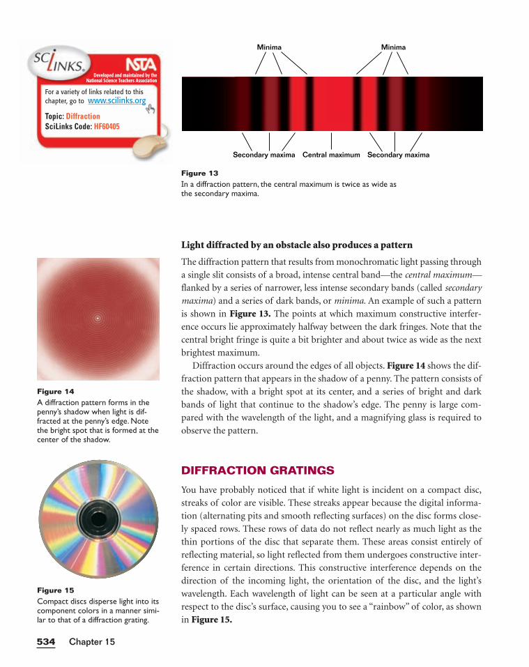
Light diffracted by an obstacle also produces a pattern
The diffraction pattern that results from monochromatic light passing through
a single slit consists of a broad, intense central band—the central maximum—
flanked by a series of narrower, less intense secondary bands (called secondary
maxima) and a series of dark bands, or minima. An example of such a pattern
is shown in Figure 13. The points at which maximum constructive interfer-
ence occurs lie approximately halfway between the dark fringes. Note that the
central bright fringe is quite a bit brighter and about twice as wide as the next
brightest maximum.
Diffraction occurs around the edges of all objects. Figure 14 shows the dif-
fraction pattern that appears in the shadow of a penny. The pattern consists of
the shadow, with a bright spot at its center, and a series of bright and dark
bands of light that continue to the shadow’s edge. The penny is large com-
pared with the wavelength of the light, and a magnifying glass is required to
observe the pattern.
DIFFRACTION GRATINGS
You have probably noticed that if white light is incident on a compact disc,
streaks of color are visible. These streaks appear because the digital informa-
tion (alternating pits and smooth reflecting surfaces) on the disc forms close-
ly spaced rows. These rows of data do not reflect nearly as much light as the
thin portions of the disc that separate them. These areas consist entirely of
reflecting material, so light reflected from them undergoes constructive inter-
ference in certain directions. This constructive interference depends on the
direction of the incoming light, the orientation of the disc, and the light’s
wavelength. Each wavelength of light can be seen at a particular angle with
respect to the disc’s surface, causing you to see a “rainbow” of color, as shown
in Figure 15.
Chapter 15534
Minima
Central maximumSecondary maxima Secondary maxima
Minima
Figure 13In a diffraction pattern, the central maximum is twice as wide asthe secondary maxima.
Figure 14A diffraction pattern forms in thepenny’s shadow when light is dif-fracted at the penny’s edge. Notethe bright spot that is formed at thecenter of the shadow.
Figure 15Compact discs disperse light into itscomponent colors in a manner simi-lar to that of a diffraction grating.
Developed and maintained by theNational Science Teachers Association
For a variety of links related to thischapter, go to www.scilinks.org
Topic: DiffractionSciLinks Code: HF60405
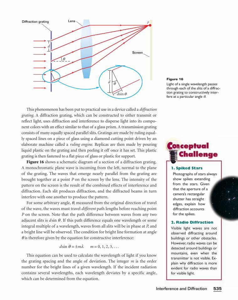
1. Spiked Stars
Photographs of stars alwaysshow spikes extendingfrom the stars. Giventhat the aperture of acamera’s rectangularshutter has straightedges, explain howdiffraction accountsfor the spikes.
2. Radio Diffraction
Visible light waves are notobserved diffracting aroundbuildings or other obstacles.However, radio waves can bedetected around buildings ormountains, even when thetransmitter is not visible. Ex-plain why diffraction is moreevident for radio waves thanfor visible light.
Diffraction grating
d
θScreen
PLens
θ
dsin θ
dFigure 16Light of a single wavelength passesthrough each of the slits of a diffrac-tion grating to constructively inter-fere at a particular angle q.
This phenomenon has been put to practical use in a device called a diffraction
grating. A diffraction grating, which can be constructed to either transmit or
reflect light, uses diffraction and interference to disperse light into its compo-
nent colors with an effect similar to that of a glass prism. A transmission grating
consists of many equally spaced parallel slits. Gratings are made by ruling equal-
ly spaced lines on a piece of glass using a diamond cutting point driven by an
elaborate machine called a ruling engine. Replicas are then made by pouring
liquid plastic on the grating and then peeling it off once it has set. This plastic
grating is then fastened to a flat piece of glass or plastic for support.
Figure 16 shows a schematic diagram of a section of a diffraction grating.
A monochromatic plane wave is incoming from the left, normal to the plane
of the grating. The waves that emerge nearly parallel from the grating are
brought together at a point P on the screen by the lens. The intensity of the
pattern on the screen is the result of the combined effects of interference and
diffraction. Each slit produces diffraction, and the diffracted beams in turn
interfere with one another to produce the pattern.
For some arbitrary angle, q, measured from the original direction of travel
of the wave, the waves must travel different path lengths before reaching point
P on the screen. Note that the path difference between waves from any two
adjacent slits is d sin q . If this path difference equals one wavelength or some
integral multiple of a wavelength, waves from all slits will be in phase at P, and
a bright line will be observed. The condition for bright line formation at angle
q is therefore given by the equation for constructive interference:
d sin q = ±ml m = 0, 1, 2, 3, . . .
This equation can be used to calculate the wavelength of light if you know
the grating spacing and the angle of deviation. The integer m is the order
number for the bright lines of a given wavelength. If the incident radiation
contains several wavelengths, each wavelength deviates by a specific angle,
which can be determined from the equation.
535Interference and Diffraction
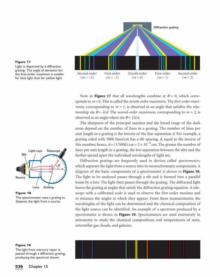
Note in Figure 17 that all wavelengths combine at q = 0, which corre-
sponds to m = 0. This is called the zeroth-order maximum. The first-order maxi-
mum, corresponding to m = 1, is observed at an angle that satisfies the rela-
tionship sin q = l/d. The second-order maximum, corresponding to m = 2, is
observed at an angle where sin q = 2l/d.
The sharpness of the principal maxima and the broad range of the dark
areas depend on the number of lines in a grating. The number of lines per
unit length in a grating is the inverse of the line separation d. For example, a
grating ruled with 5000 lines/cm has a slit spacing, d, equal to the inverse of
this number; hence, d = (1/5000) cm = 2 × 10⁻⁴ cm. The greater the number of
lines per unit length in a grating, the less separation between the slits and the
farther spread apart the individual wavelengths of light are.
Diffraction gratings are frequently used in devices called spectrometers,
which separate the light from a source into its monochromatic components. A
diagram of the basic components of a spectrometer is shown in Figure 18.The light to be analyzed passes through a slit and is formed into a parallel
beam by a lens. The light then passes through the grating. The diffracted light
leaves the grating at angles that satisfy the diffraction grating equation. A tele-
scope with a calibrated scale is used to observe the first-order maxima and
to measure the angles at which they appear. From these measurements, the
wavelengths of the light can be determined and the chemical composition of
the light source can be identified. An example of a spectrum produced by a
spectrometer is shown in Figure 19. Spectrometers are used extensively in
astronomy to study the chemical compositions and temperatures of stars,
interstellar gas clouds, and galaxies.
Chapter 15536
First order(m = 1)
First order(m = –1)
Second order(m = 2)
Second order(m = –2)
Zeroth order(m = 0)
Diffraction grating
Figure 17Light is dispersed by a diffractiongrating. The angle of deviation forthe first-order maximum is smallerfor blue light than for yellow light.
Grating
Light rays TelescopeSlit
Source
Lens
θ
Figure 18The spectrometer uses a grating todisperse the light from a source.
Figure 19The light from mercury vapor ispassed through a diffraction grating,producing the spectrum shown.
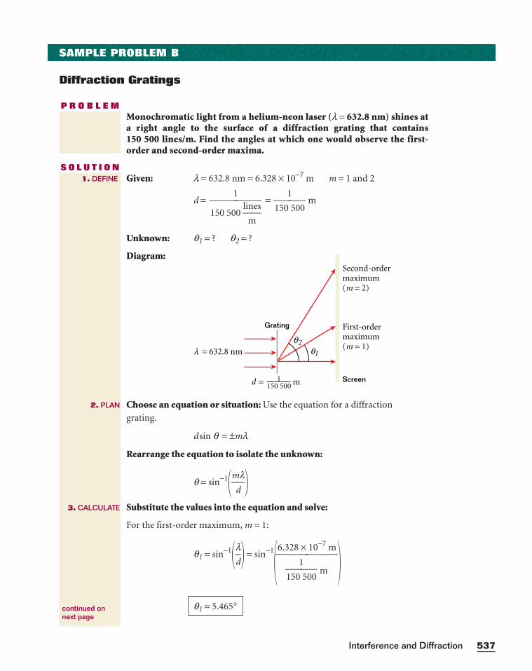
537Interference and Diffraction
SAMPLE PROBLEM B
Diffraction Gratings
P R O B L E MMonochromatic light from a helium-neon laser (l = 632.8 nm) shines ata right angle to the surface of a diffraction grating that contains 150 500 lines/m. Find the angles at which one would observe the first-order and second-order maxima.
S O L U T I O NGiven: l = 632.8 nm = 6.328 × 10⁻⁷ m m = 1 and 2
d = = 150
1
500 m
Unknown: q1 = ? q2 = ?
Diagram:
Choose an equation or situation: Use the equation for a diffraction
grating.
d sin q = ±ml
Rearrange the equation to isolate the unknown:
q = sin−1�m
d
l�
Substitute the values into the equation and solve:
For the first-order maximum, m = 1:
q1 = sin−1�ld
� = sin−1� �q1 = 5.465°
6.328 × 10⁻⁷ m
150
1
500 m
Second-ordermaximum(m = 2)
First-ordermaximum(m = 1)
Screen
Grating
d m= 1150 500
2θ1θ= 632.8 nmλ
1150 500
li
m
nes
1. DEFINE
2. PLAN
3. CALCULATE
continued onnext page
Chapter 15538
For m = 2:
q2 = sin−1�2
d
l�
q2 = sin−1� �The second-order maximum is spread slightly more than twice as far from the
center as the first-order maximum. This diffraction grating does not have
high dispersion, and it can produce spectral lines up to the tenth-order maxima
(where sin q = 0.9524).
q2 = 10.98°
2(6.328 × 10⁻⁷ m)
150
1
500 m
4. EVALUATE
CALCULATOR SOLUTION
Because the minimum number of sig-nificant figures for the data is four,the calculator answers 5.464926226and 10.98037754 should be roundedto four significant figures.
PRACTICE B
Diffraction Gratings
1. A diffraction grating with 5.000 × 10³ lines/cm is used to examine the
sodium spectrum. Calculate the angular separation of the two closely
spaced yellow lines of sodium (588.995 nm and 589.592 nm) in each of
the first three orders.
2. A diffraction grating with 4525 lines/cm is illuminated by direct sunlight. The
first-order solar spectrum is spread out on a white screen hanging on a wall
opposite the grating.
a. At what angle does the first-order maximum for blue light with a wave-
length of 422 nm appear?
b. At what angle does the first-order maximum for red light with a wave-
length of 655 nm appear?
3. A grating with 1555 lines/cm is illuminated with light of wavelength
565 nm. What is the highest-order number that can be observed with this
grating? (Hint: Remember that sin q can never be greater than 1 for a dif-
fraction grating.)
4. Repeat item 3 for a diffraction grating with 15 550 lines/cm that is illu-
minated with light of wavelength 565 nm.
5. A diffraction grating is calibrated by using the 546.1 nm line of mercury
vapor. The first-order maximum is found at an angle of 21.2°. Calculate
the number of lines per centimeter on this grating.
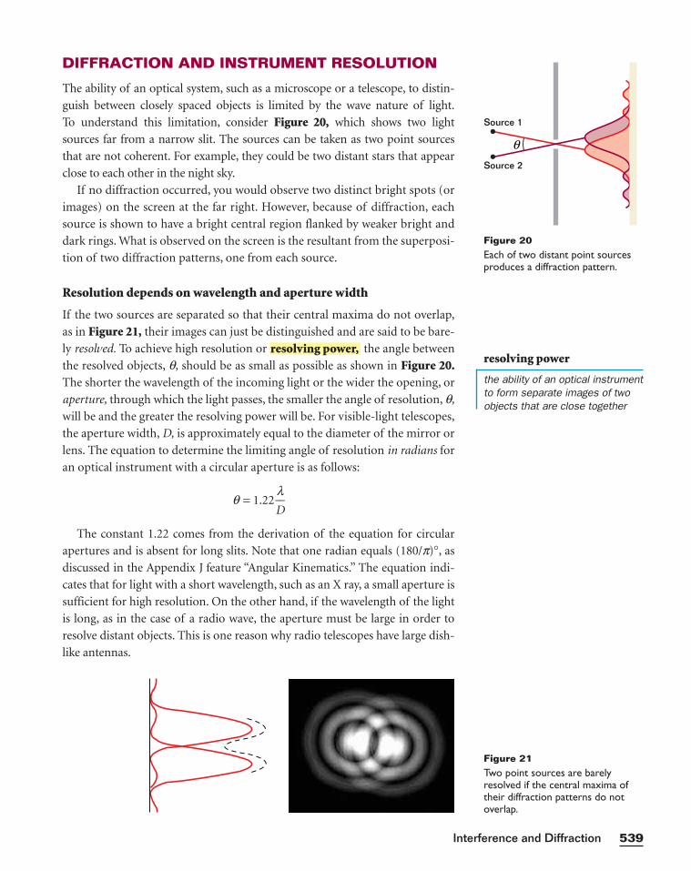
DIFFRACTION AND INSTRUMENT RESOLUTION
The ability of an optical system, such as a microscope or a telescope, to distin-
guish between closely spaced objects is limited by the wave nature of light.
To understand this limitation, consider Figure 20, which shows two light
sources far from a narrow slit. The sources can be taken as two point sources
that are not coherent. For example, they could be two distant stars that appear
close to each other in the night sky.
If no diffraction occurred, you would observe two distinct bright spots (or
images) on the screen at the far right. However, because of diffraction, each
source is shown to have a bright central region flanked by weaker bright and
dark rings. What is observed on the screen is the resultant from the superposi-
tion of two diffraction patterns, one from each source.
Resolution depends on wavelength and aperture width
If the two sources are separated so that their central maxima do not overlap,
as in Figure 21, their images can just be distinguished and are said to be bare-
ly resolved. To achieve high resolution or the angle between
the resolved objects, q, should be as small as possible as shown in Figure 20.The shorter the wavelength of the incoming light or the wider the opening, or
aperture, through which the light passes, the smaller the angle of resolution, q,
will be and the greater the resolving power will be. For visible-light telescopes,
the aperture width, D, is approximately equal to the diameter of the mirror or
lens. The equation to determine the limiting angle of resolution in radians for
an optical instrument with a circular aperture is as follows:
q = 1.22 D
l
The constant 1.22 comes from the derivation of the equation for circular
apertures and is absent for long slits. Note that one radian equals (180/p)°, as
discussed in the Appendix J feature “Angular Kinematics.” The equation indi-
cates that for light with a short wavelength, such as an X ray, a small aperture is
sufficient for high resolution. On the other hand, if the wavelength of the light
is long, as in the case of a radio wave, the aperture must be large in order to
resolve distant objects. This is one reason why radio telescopes have large dish-
like antennas.
resolving power,
539Interference and Diffraction
Source 1
Source 2
θ
Figure 20Each of two distant point sourcesproduces a diffraction pattern.
Figure 21Two point sources are barelyresolved if the central maxima oftheir diffraction patterns do notoverlap.
resolving power
the ability of an optical instrumentto form separate images of twoobjects that are close together
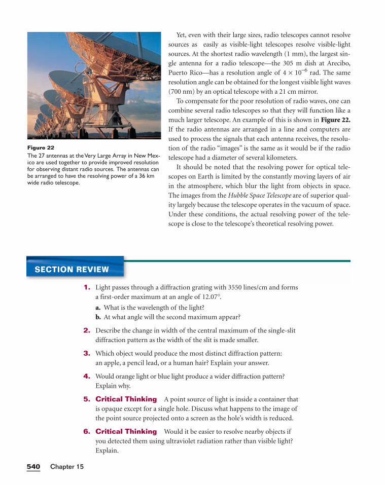
Yet, even with their large sizes, radio telescopes cannot resolve
sources as easily as visible-light telescopes resolve visible-light
sources. At the shortest radio wavelength (1 mm), the largest sin-
gle antenna for a radio telescope—the 305 m dish at Arecibo,
Puerto Rico—has a resolution angle of 4 × 10⁻⁶ rad. The same
resolution angle can be obtained for the longest visible light waves
(700 nm) by an optical telescope with a 21 cm mirror.
To compensate for the poor resolution of radio waves, one can
combine several radio telescopes so that they will function like a
much larger telescope. An example of this is shown in Figure 22.If the radio antennas are arranged in a line and computers are
used to process the signals that each antenna receives, the resolu-
tion of the radio “images” is the same as it would be if the radio
telescope had a diameter of several kilometers.
It should be noted that the resolving power for optical tele-
scopes on Earth is limited by the constantly moving layers of air
in the atmosphere, which blur the light from objects in space.
The images from the Hubble Space Telescope are of superior qual-
ity largely because the telescope operates in the vacuum of space.
Under these conditions, the actual resolving power of the tele-
scope is close to the telescope’s theoretical resolving power.
Chapter 15540
Figure 22The 27 antennas at the Very Large Array in New Mex-ico are used together to provide improved resolutionfor observing distant radio sources. The antennas canbe arranged to have the resolving power of a 36 kmwide radio telescope.
SECTION REVIEW
1. Light passes through a diffraction grating with 3550 lines/cm and forms
a first-order maximum at an angle of 12.07°.a. What is the wavelength of the light?
b. At what angle will the second maximum appear?
2. Describe the change in width of the central maximum of the single-slit
diffraction pattern as the width of the slit is made smaller.
3. Which object would produce the most distinct diffraction pattern:
an apple, a pencil lead, or a human hair? Explain your answer.
4. Would orange light or blue light produce a wider diffraction pattern?
Explain why.
5. Critical Thinking A point source of light is inside a container that
is opaque except for a single hole. Discuss what happens to the image of
the point source projected onto a screen as the hole’s width is reduced.
6. Critical Thinking Would it be easier to resolve nearby objects if
you detected them using ultraviolet radiation rather than visible light?
Explain.
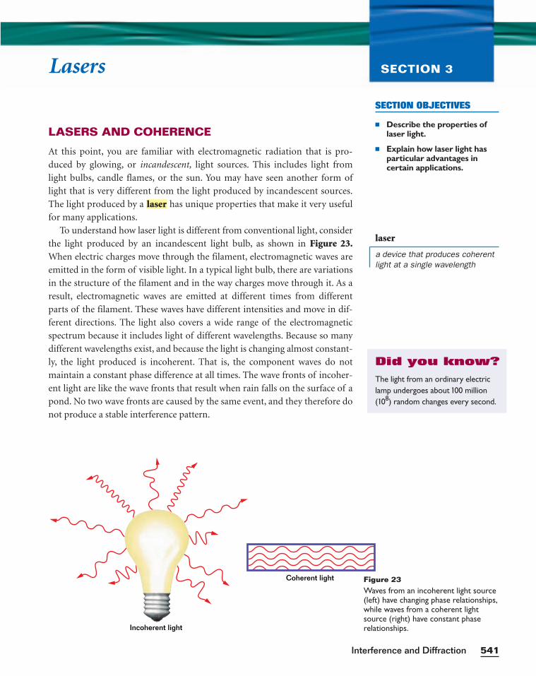
SECTION OBJECTIVES
■ Describe the properties oflaser light.
■ Explain how laser light hasparticular advantages in certain applications.
541Interference and Diffraction
Lasers SECTION 3
LASERS AND COHERENCE
At this point, you are familiar with electromagnetic radiation that is pro-
duced by glowing, or incandescent, light sources. This includes light from
light bulbs, candle flames, or the sun. You may have seen another form of
light that is very different from the light produced by incandescent sources.
The light produced by a has unique properties that make it very useful
for many applications.
To understand how laser light is different from conventional light, consider
the light produced by an incandescent light bulb, as shown in Figure 23.When electric charges move through the filament, electromagnetic waves are
emitted in the form of visible light. In a typical light bulb, there are variations
in the structure of the filament and in the way charges move through it. As a
result, electromagnetic waves are emitted at different times from different
parts of the filament. These waves have different intensities and move in dif-
ferent directions. The light also covers a wide range of the electromagnetic
spectrum because it includes light of different wavelengths. Because so many
different wavelengths exist, and because the light is changing almost constant-
ly, the light produced is incoherent. That is, the component waves do not
maintain a constant phase difference at all times. The wave fronts of incoher-
ent light are like the wave fronts that result when rain falls on the surface of a
pond. No two wave fronts are caused by the same event, and they therefore do
not produce a stable interference pattern.
laser
Incoherent light
Coherent light Figure 23Waves from an incoherent light source(left) have changing phase relationships,while waves from a coherent lightsource (right) have constant phase relationships.
laser
a device that produces coherentlight at a single wavelength
The light from an ordinary electriclamp undergoes about 100 million(108) random changes every second.
Did you know?
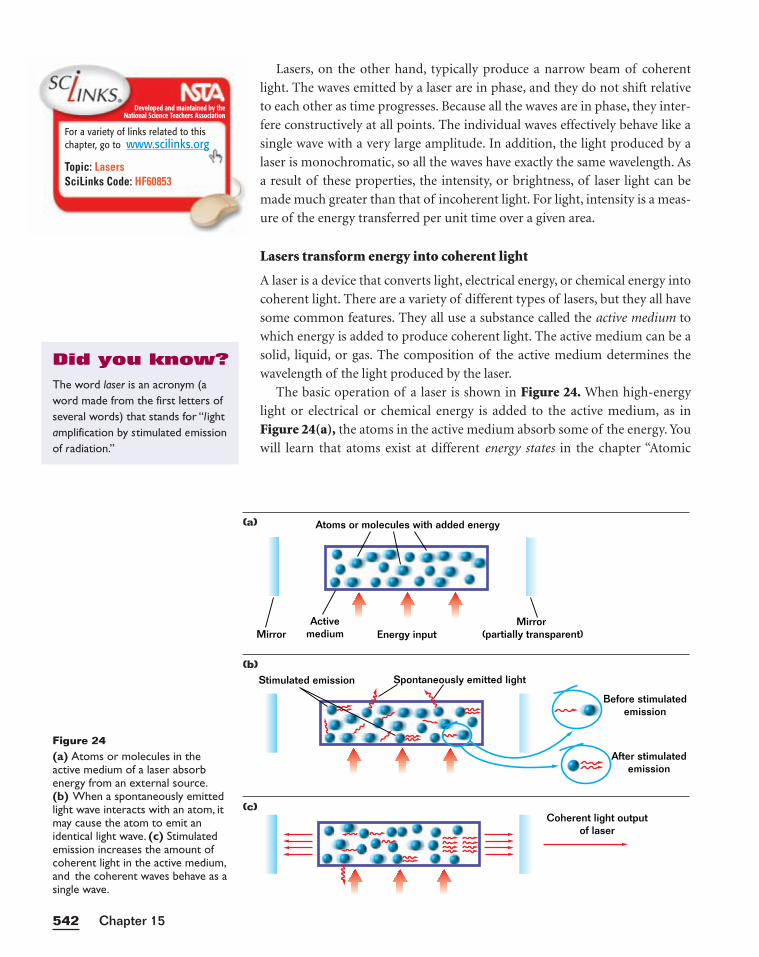
Lasers, on the other hand, typically produce a narrow beam of coherent
light. The waves emitted by a laser are in phase, and they do not shift relative
to each other as time progresses. Because all the waves are in phase, they inter-
fere constructively at all points. The individual waves effectively behave like a
single wave with a very large amplitude. In addition, the light produced by a
laser is monochromatic, so all the waves have exactly the same wavelength. As
a result of these properties, the intensity, or brightness, of laser light can be
made much greater than that of incoherent light. For light, intensity is a meas-
ure of the energy transferred per unit time over a given area.
Lasers transform energy into coherent light
A laser is a device that converts light, electrical energy, or chemical energy into
coherent light. There are a variety of different types of lasers, but they all have
some common features. They all use a substance called the active medium to
which energy is added to produce coherent light. The active medium can be a
solid, liquid, or gas. The composition of the active medium determines the
wavelength of the light produced by the laser.
The basic operation of a laser is shown in Figure 24. When high-energy
light or electrical or chemical energy is added to the active medium, as in
Figure 24(a), the atoms in the active medium absorb some of the energy. You
will learn that atoms exist at different energy states in the chapter “Atomic
Chapter 15542
Atoms or molecules with added energy
MirrorMirror
(partially transparent)Energy inputActive
medium
Figure 24(a) Atoms or molecules in theactive medium of a laser absorb energy from an external source.(b) When a spontaneously emittedlight wave interacts with an atom, itmay cause the atom to emit anidentical light wave. (c) Stimulatedemission increases the amount ofcoherent light in the active medium,and the coherent waves behave as asingle wave.
Stimulated emission Spontaneously emitted light
Before stimulatedemission
After stimulatedemission
Coherent light outputof laser
(a)
(b)
(c)
Developed and maintained by theNational Science Teachers Association
For a variety of links related to thischapter, go to www.scilinks.org
Topic: LasersSciLinks Code: HF60853
The word laser is an acronym (aword made from the first letters ofseveral words) that stands for “l ightamplification by stimulated emissionof radiation.”
Did you know?
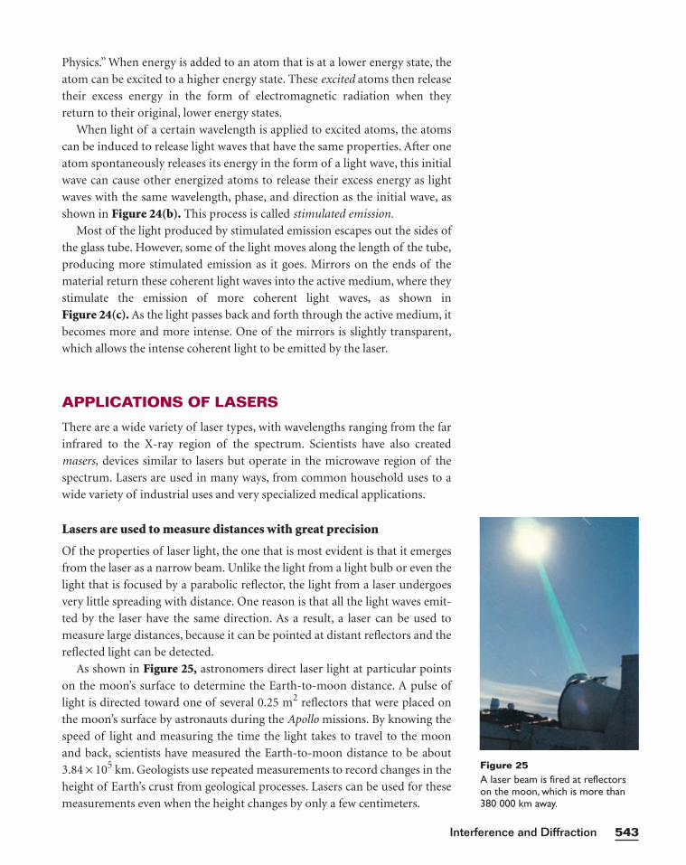
Physics.” When energy is added to an atom that is at a lower energy state, the
atom can be excited to a higher energy state. These excited atoms then release
their excess energy in the form of electromagnetic radiation when they
return to their original, lower energy states.
When light of a certain wavelength is applied to excited atoms, the atoms
can be induced to release light waves that have the same properties. After one
atom spontaneously releases its energy in the form of a light wave, this initial
wave can cause other energized atoms to release their excess energy as light
waves with the same wavelength, phase, and direction as the initial wave, as
shown in Figure 24(b). This process is called stimulated emission.
Most of the light produced by stimulated emission escapes out the sides of
the glass tube. However, some of the light moves along the length of the tube,
producing more stimulated emission as it goes. Mirrors on the ends of the
material return these coherent light waves into the active medium, where they
stimulate the emission of more coherent light waves, as shown in
Figure 24(c). As the light passes back and forth through the active medium, it
becomes more and more intense. One of the mirrors is slightly transparent,
which allows the intense coherent light to be emitted by the laser.
APPLICATIONS OF LASERS
There are a wide variety of laser types, with wavelengths ranging from the far
infrared to the X-ray region of the spectrum. Scientists have also created
masers, devices similar to lasers but operate in the microwave region of the
spectrum. Lasers are used in many ways, from common household uses to a
wide variety of industrial uses and very specialized medical applications.
Lasers are used to measure distances with great precision
Of the properties of laser light, the one that is most evident is that it emerges
from the laser as a narrow beam. Unlike the light from a light bulb or even the
light that is focused by a parabolic reflector, the light from a laser undergoes
very little spreading with distance. One reason is that all the light waves emit-
ted by the laser have the same direction. As a result, a laser can be used to
measure large distances, because it can be pointed at distant reflectors and the
reflected light can be detected.
As shown in Figure 25, astronomers direct laser light at particular points
on the moon’s surface to determine the Earth-to-moon distance. A pulse of
light is directed toward one of several 0.25 m2 reflectors that were placed on
the moon’s surface by astronauts during the Apollo missions. By knowing the
speed of light and measuring the time the light takes to travel to the moon
and back, scientists have measured the Earth-to-moon distance to be about
3.84 × 10⁵ km. Geologists use repeated measurements to record changes in the
height of Earth’s crust from geological processes. Lasers can be used for these
measurements even when the height changes by only a few centimeters.
543Interference and Diffraction
Figure 25A laser beam is fired at reflectorson the moon, which is more than380 000 km away.
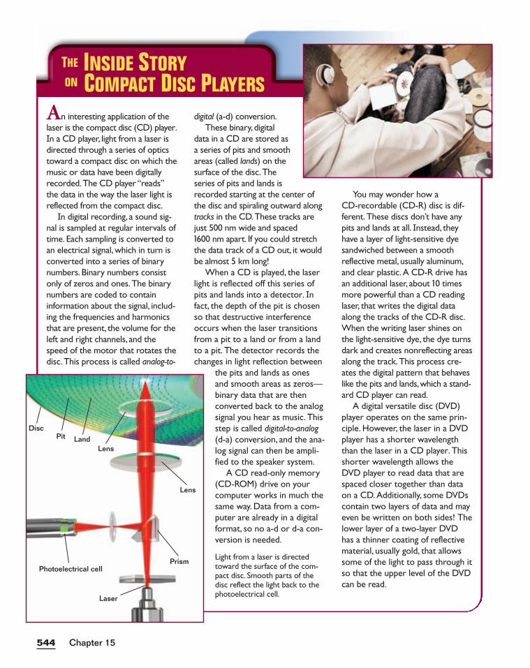
Chapter 15544
An interesting application of thelaser is the compact disc (CD) player.In a CD player, light from a laser isdirected through a series of opticstoward a compact disc on which themusic or data have been digitallyrecorded.The CD player “reads”the data in the way the laser light isreflected from the compact disc.
In digital recording, a sound sig-nal is sampled at regular intervals oftime. Each sampling is converted toan electrical signal, which in turn isconverted into a series of binarynumbers. Binary numbers consistonly of zeros and ones. The binarynumbers are coded to containinformation about the signal, includ-ing the frequencies and harmonicsthat are present, the volume for theleft and right channels, and thespeed of the motor that rotates thedisc. This process is called analog-to-
digital (a-d) conversion.These binary, digital
data in a CD are stored asa series of pits and smoothareas (called lands) on thesurface of the disc.Theseries of pits and lands isrecorded starting at the center ofthe disc and spiraling outward alongtracks in the CD.These tracks arejust 500 nm wide and spaced1600 nm apart. If you could stretchthe data track of a CD out, it wouldbe almost 5 km long!
When a CD is played, the laserlight is reflected off this series ofpits and lands into a detector. Infact, the depth of the pit is chosenso that destructive interferenceoccurs when the laser transitionsfrom a pit to a land or from a landto a pit. The detector records thechanges in light reflection between
the pits and lands as onesand smooth areas as zeros—binary data that are thenconverted back to the analogsignal you hear as music. Thisstep is called digital-to-analog(d-a) conversion, and the ana-log signal can then be ampli-fied to the speaker system.
A CD read-only memory(CD-ROM) drive on yourcomputer works in much thesame way. Data from a com-puter are already in a digitalformat, so no a-d or d-a con-version is needed.
You may wonder how aCD-recordable (CD-R) disc is dif-ferent. These discs don’t have anypits and lands at all. Instead, theyhave a layer of light-sensitive dyesandwiched between a smoothreflective metal, usually aluminum,and clear plastic. A CD-R drive hasan additional laser, about 10 timesmore powerful than a CD readinglaser, that writes the digital dataalong the tracks of the CD-R disc.When the writing laser shines onthe light-sensitive dye, the dye turnsdark and creates nonreflecting areasalong the track. This process cre-ates the digital pattern that behaveslike the pits and lands,which a stand-ard CD player can read.
A digital versatile disc (DVD)player operates on the same prin-ciple. However, the laser in a DVDplayer has a shorter wavelengththan the laser in a CD player. Thisshorter wavelength allows theDVD player to read data that arespaced closer together than dataon a CD. Additionally, some DVDscontain two layers of data and mayeven be written on both sides! Thelower layer of a two-layer DVDhas a thinner coating of reflectivematerial, usually gold, that allowssome of the light to pass through itso that the upper level of the DVDcan be read.
THE INSIDE STORYON COMPACT DISC PLAYERS
DiscPit Land
Photoelectrical cell
Lens
Laser
Lens
Prism Light from a laser is directedtoward the surface of the com-pact disc. Smooth parts of thedisc reflect the light back to thephotoelectrical cell.
Lasers have many applications in medicine
Lasers are also used for many medical procedures by making use of the fact that
specific body tissues absorb different wavelengths of laser light. For example,
lasers can be used to lighten or remove scars and certain types of birthmarks
without affecting surrounding tissues. The scar tissue responds to the wave-
length of light used in the laser, but other body tissues are protected.
Many medical applications of lasers take advantage of the fact that water
can be vaporized by high-intensity infrared light produced by carbon dioxide
lasers having a wavelength of 10 �m. Carbon dioxide lasers can cut through
muscle tissue by heating and evaporating the water contained in the cells. One
advantage of a laser is that the energy from the laser also coagulates blood in
the newly opened blood vessels, thereby reducing blood loss and decreasing
the risk of infection. A laser beam can also be trapped in an optical fiber endo-
scope, which can be inserted through an orifice and directed to internal body
structures. As a result, surgeons can stop internal bleeding or remove tumors
without performing massive surgery.
Lasers can also be used to treat tissues that cannot be reached by conven-
tional surgical methods. For example, some very specific wavelengths of lasers
can pass through certain structures at the front of the eye—the cornea and
lens—without damaging them. Therefore, lasers can be effective at treating
lesions of the retina, inside the eye. Lasers are used for other eye surgeries,
including surgery to correct glaucoma, a condition in which the fluid pressure
within the eye is too great. Left untreated, glaucoma can lead to damage of the
optic nerve and eventual blindness. Focusing a laser at the clogged drainage
port allows a tiny hole to be burned in the tissue, which relieves the pressure.
Lasers can also be used to correct nearsightedness by focusing the beam on the
central portion of the cornea to cause it to become flatter.
545Interference and Diffraction
Did you know?
Developed and maintained by theNational Science Teachers Association
For a variety of links related to thischapter, go to www.scilinks.org
Topic: Bar CodesSciLinks Code: HF60135
The principle behind reading theinformation stored on a compactdisc is also the basis for the read-ing of bar codes found on manyproducts. When these productsare scanned, laser light reflectedfrom the bars and spaces of thebar code reproduces the binarycodes that represent the product’sinventory number. This informa-tion is transmitted to the store’scomputer system, which returnsthe product’s name and price tothe cash register.
SECTION REVIEW
1. How does light from a laser differ from light whose waves all have the
same wavelength but are not coherent?
2. The process of stimulated emission involves producing a second wave
that is identical to the first. Does this gaining of a second wave violate the
principle of energy conservation? Explain your answer.
3. Critical Thinking Fiber-optic systems transmit light by means of
internal reflection within thin strands of extremely pure glass. In these
fiber-optic systems, laser light is used instead of white light to transmit the
signal. Apply your knowledge of refraction to explain why.

546546
Laser Surgeon
What is your favorite thing about your job?What would you most like to change about it?
My favorite thing is making people visually free. Iwould like to be able to solve an even wider range ofproblems.We can’t solve everything.
How does your work relate to the physics ofinterference and diffraction?
Measuring diffraction and interference is part ofevery aspect of what we do. The approach isbased on doing many small things correctly.Applying small physics principles in the rightorder can solve very big problems.
What advice would you give to some-body who is considering a career in
laser surgery?My education didn’t start in medical
school; it started by asking questionsas a kid. You need a genuine love oftaking on complex problems. A
background in physics and mathis extremely helpful. Technol-
ogy in medicine is based onengineering.
Being well rounded will helpyou get into medicalschool—and get out, too.You have to be comfortable
doing the science, but youalso have to be comfortable deal-
ing with people.
PHYSICS
CAREERS
Dr.Wong makes measurements of the eye inpreparation for laser surgery.
Laser surgery combines two fields—eyecare and high-tech engineering—to giveperfect vision to people who otherwisewould need glasses or contacts. To learnmore about this career, read the interviewwith ophthalmologist Dr. L. Shawn Wong,who runs a laser center in Austin, Texas.
What sort of education helped you become alaser surgeon?
Besides using my medical school training, I use a lot ofengineering in my work; physics and math courses arevery helpful. In high school, even in junior high, havinga love of math and science is extremely helpful.
Who helped you find your career path?Of all my teachers, my junior high earth scienceteacher made the biggest impression on me.What Ilearned in those classes I actually still use today:problem solving. Interestingly, I work in thetown where I grew up; a lot of my formerteachers are my patients today.
What makes laser surgery interesting to you?
It’s nice to be able to help people. Unlikeglasses and contacts, laser surgery is not a correction; it’s a cure.When you are improv-ing people’s vision, everybody in theroom gets to see the results. I don’tneed to tell patients they’re doingwell—they can tell.
What is the nature of yourwork?
A typical patient is somebodyborn with poor vision.We makethese patients undergo a lot of for-mal diagnostic testing and informalscreening to be sure they are goodcandidates. Lasers are used for diag-nosing as well as treating. Laser toler-ances are extremely small—we’retalking in terms of submicrons, the indi-vidual cells of the eye.
Chapter 15
KEY IDEAS
Section 1 Interference• Light waves with the same wavelength and constant phase differences
interfere with each other to produce light and dark interference patterns.
• In double-slit interference, the position of a bright fringe requires that the
path difference between two interfering point sources be equal to a whole
number of wavelengths.
• In double-slit interference, the position of a dark fringe requires that the
path difference between two interfering point sources be equal to an odd
number of half wavelengths.
Section 2 Diffraction• Light waves form a diffraction pattern by passing around an obstacle or
bending through a slit and interfering with each other.
• The position of a maximum in a pattern created by a diffraction grating
depends on the separation of the slits in the grating, the order of the maxi-
mum, and the wavelength of the light.
Section 3 Lasers• A laser is a device that transforms energy into a beam of coherent mono-
chromatic light.
KEY TERMS
coherence (p. 527)
path difference (p. 529)
order number (p. 529)
diffraction (p. 532)
resolving power (p. 539)
laser (p. 541)
HighlightsCHAPTER 15
547Interference and Diffraction
PROBLEM SOLVING
See Appendix D: Equations for a summary of the equationsintroduced in this chapter. Ifyou need more problem-solvingpractice, see Appendix I: Additional Problems.
Variable Symbols
Quantities Units
l wavelength m meters
q angle from the center ° degreesof an interference pattern
d slit separation m meters
m order number (unitless)
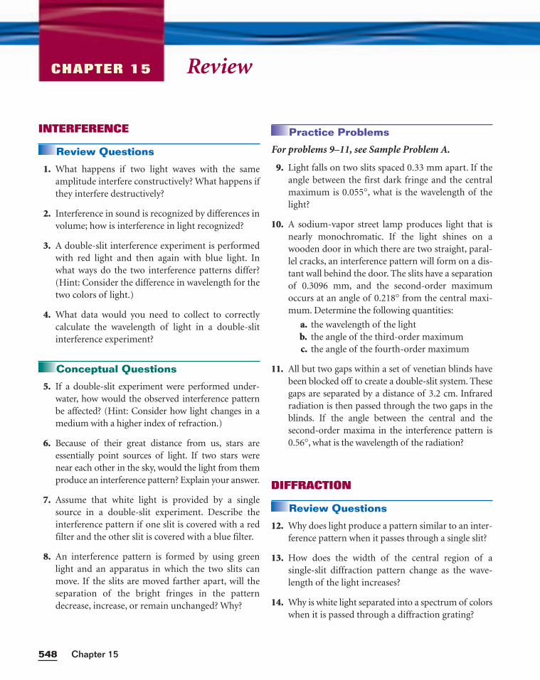
ReviewCHAPTER 15
INTERFERENCE
Review Questions
1. What happens if two light waves with the sameamplitude interfere constructively? What happens ifthey interfere destructively?
2. Interference in sound is recognized by differences involume; how is interference in light recognized?
3. A double-slit interference experiment is performedwith red light and then again with blue light. Inwhat ways do the two interference patterns differ?(Hint: Consider the difference in wavelength for thetwo colors of light.)
4. What data would you need to collect to correctlycalculate the wavelength of light in a double-slitinterference experiment?
Conceptual Questions
5. If a double-slit experiment were performed under-water, how would the observed interference patternbe affected? (Hint: Consider how light changes in amedium with a higher index of refraction.)
6. Because of their great distance from us, stars areessentially point sources of light. If two stars werenear each other in the sky, would the light from themproduce an interference pattern? Explain your answer.
7. Assume that white light is provided by a singlesource in a double-slit experiment. Describe theinterference pattern if one slit is covered with a redfilter and the other slit is covered with a blue filter.
8. An interference pattern is formed by using greenlight and an apparatus in which the two slits canmove. If the slits are moved farther apart, will theseparation of the bright fringes in the patterndecrease, increase, or remain unchanged? Why?
Practice Problems
For problems 9–11, see Sample Problem A.
9. Light falls on two slits spaced 0.33 mm apart. If theangle between the first dark fringe and the centralmaximum is 0.055°, what is the wavelength of thelight?
10. A sodium-vapor street lamp produces light that isnearly monochromatic. If the light shines on awooden door in which there are two straight, paral-lel cracks, an interference pattern will form on a dis-tant wall behind the door. The slits have a separationof 0.3096 mm, and the second-order maximumoccurs at an angle of 0.218° from the central maxi-mum. Determine the following quantities:
a. the wavelength of the lightb. the angle of the third-order maximumc. the angle of the fourth-order maximum
11. All but two gaps within a set of venetian blinds havebeen blocked off to create a double-slit system. Thesegaps are separated by a distance of 3.2 cm. Infraredradiation is then passed through the two gaps in theblinds. If the angle between the central and the second-order maxima in the interference pattern is0.56°, what is the wavelength of the radiation?
DIFFRACTION
Review Questions
12. Why does light produce a pattern similar to an inter-ference pattern when it passes through a single slit?
13. How does the width of the central region of a single-slit diffraction pattern change as the wave-length of the light increases?
14. Why is white light separated into a spectrum of colorswhen it is passed through a diffraction grating?
Chapter 15548
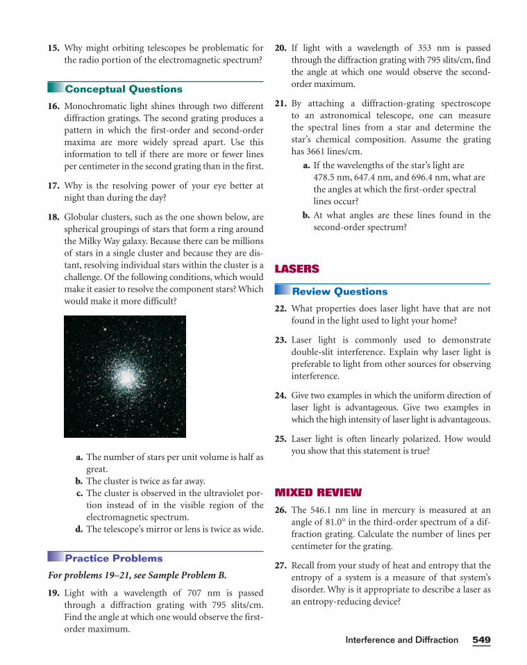
15. Why might orbiting telescopes be problematic forthe radio portion of the electromagnetic spectrum?
Conceptual Questions
16. Monochromatic light shines through two differentdiffraction gratings. The second grating produces apattern in which the first-order and second-ordermaxima are more widely spread apart. Use thisinformation to tell if there are more or fewer linesper centimeter in the second grating than in the first.
17. Why is the resolving power of your eye better atnight than during the day?
18. Globular clusters, such as the one shown below, arespherical groupings of stars that form a ring aroundthe Milky Way galaxy. Because there can be millionsof stars in a single cluster and because they are dis-tant, resolving individual stars within the cluster is achallenge. Of the following conditions, which wouldmake it easier to resolve the component stars? Whichwould make it more difficult?
a. The number of stars per unit volume is half asgreat.
b. The cluster is twice as far away.c. The cluster is observed in the ultraviolet por-
tion instead of in the visible region of theelectromagnetic spectrum.
d. The telescope’s mirror or lens is twice as wide.
Practice Problems
For problems 19–21, see Sample Problem B.
19. Light with a wavelength of 707 nm is passedthrough a diffraction grating with 795 slits/cm.Find the angle at which one would observe the first-order maximum.
20. If light with a wavelength of 353 nm is passedthrough the diffraction grating with 795 slits/cm, findthe angle at which one would observe the second-order maximum.
21. By attaching a diffraction-grating spectroscope to an astronomical telescope, one can measure the spectral lines from a star and determine thestar’s chemical composition. Assume the gratinghas 3661 lines/cm.
a. If the wavelengths of the star’s light are 478.5 nm, 647.4 nm, and 696.4 nm, what arethe angles at which the first-order spectrallines occur?
b. At what angles are these lines found in thesecond-order spectrum?
LASERS
Review Questions
22. What properties does laser light have that are notfound in the light used to light your home?
23. Laser light is commonly used to demonstrate double-slit interference. Explain why laser light ispreferable to light from other sources for observinginterference.
24. Give two examples in which the uniform direction oflaser light is advantageous. Give two examples inwhich the high intensity of laser light is advantageous.
25. Laser light is often linearly polarized. How wouldyou show that this statement is true?
MIXED REVIEW
26. The 546.1 nm line in mercury is measured at anangle of 81.0° in the third-order spectrum of a dif-fraction grating. Calculate the number of lines percentimeter for the grating.
27. Recall from your study of heat and entropy that theentropy of a system is a measure of that system’sdisorder. Why is it appropriate to describe a laser asan entropy-reducing device?
549Interference and Diffraction
28. A double-slit interference experiment is performedusing blue light from a hydrogen discharge tube (l = 486 nm). The fifth-order bright fringe in theinterference pattern is 0.578° from the central maxi-mum. How far apart are the two slits separated?
29. A beam containing light of wavelengths l1 and l2passes through a set of parallel slits. In the interfer-ence pattern, the fourth bright line of the l1 lightoccurs at the same position as the fifth bright line ofthe l2 light. If l1 is known to be 540.0 nm, what isthe value of l2?
30. Visible light from an incandescent light bulb rangesfrom 400.0 nm to 700.0 nm. When this light isfocused on a diffraction grating, the entire first-order spectrum is seen, but none of the second-order spectrum is seen. What is the maximumspacing between lines on this grating?
31. In an arrangement to demonstrate double-slit inter-ference, l = 643 nm, q = 0.737°, and d = 0.150 mm.For light from the two slits interfering at this angle,what is the path difference both in millimeters andin terms of the number of wavelengths? Will theinterference correspond to a maximum, a mini-mum, or an intermediate condition?
Chapter 15550
1. Design simulations of interference patterns. Use a
computer to draw many concentric circles at regular
distances to represent waves traveling from a point
source. Photocopy the page onto two transparencies,
and lay them on an overhead projector. Vary the dis-
tances between “source points,” and observe how these
variations affect interference patterns. Design trans-
parencies with thicker lines with larger separations to
explore the effect of wavelength on interference.
2. Investigate the effect of slit separation on interfer-
ence patterns. Wrap a flashlight or a pen light tightly
with tin foil and make pinholes in the foil. First,
record the pattern you see on a screen a few inches
away with one hole; then, do the same with two holes.
How does the distance between the holes affect the
distance between the bright parts of the pattern?
Draw schematic diagrams of your observations, and
compare them with the results of double-slit interfer-
ence. How would you improve your equipment?
3. Soap bubbles exhibit different colors because light
that is reflected from the outer layer of the soap film
interferes with light that is refracted and then re-
flected from the inner layer of the soap film. Given a
refractive index of n = 1.35 and thicknesses ranging
from 600 nm to 1000 nm for a soap film, can you
predict the colors of a bubble? Test your answer by
making soap bubbles and observing the order in
which the different colors appear. Can you tell the
thickness of a soap bubble from its colors? Organize
your findings into a chart, or create a computer pro-
gram to predict the thicknesses of a bubble based on
the wavelengths of light it appears to reflect.
4. Thomas Young’s 1803 experiment provided crucial
evidence for the wave nature of light, but it was met
with strong opposition in England until Augustin
Fresnel presented his wave theory of light to the
French Academy of Sciences in 1819. Research the
lives and careers of these two scientists. Create a
presentation about one of them. The presentation
can be in the form of a report, poster, short video,
or computer presentation.
5. Research waves that surround you, including those
used in commercial, medicinal, and industrial
applications. Interpret how the waves’ characteris-
tics and behaviors make them useful. For example,
investigate what kinds of waves are used in medical
procedures such as MRI and ultrasound. What are
their wavelengths? Research how lasers are used in
medicine. How are they used in industry? Prepare a
poster or chart describing your findings, and pre-
sent it to the class.
Alternative Assessment
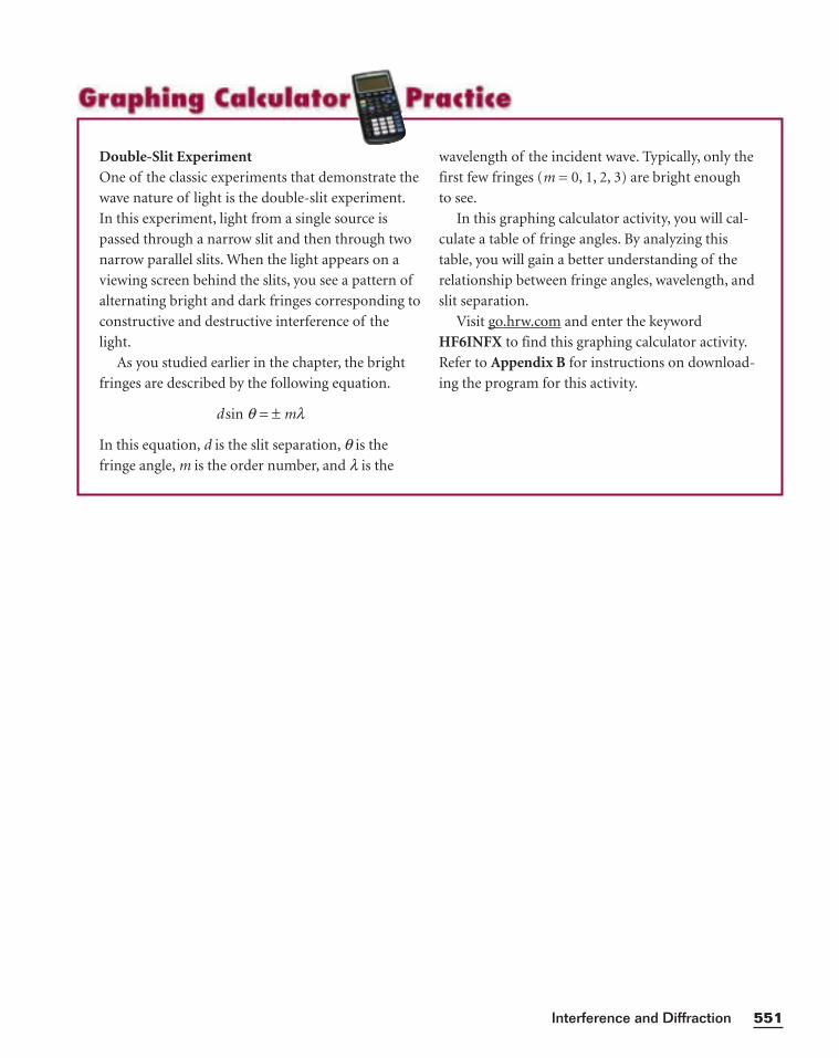
551Interference and Diffraction
wavelength of the incident wave. Typically, only the
first few fringes (m = 0, 1, 2, 3) are bright enough
to see.
In this graphing calculator activity, you will cal-
culate a table of fringe angles. By analyzing this
table, you will gain a better understanding of the
relationship between fringe angles, wavelength, and
slit separation.
Visit go.hrw.com and enter the keyword
HF6INFX to find this graphing calculator activity.
Refer to Appendix B for instructions on download-
ing the program for this activity.
Double-Slit ExperimentOne of the classic experiments that demonstrate the
wave nature of light is the double-slit experiment.
In this experiment, light from a single source is
passed through a narrow slit and then through two
narrow parallel slits. When the light appears on a
viewing screen behind the slits, you see a pattern of
alternating bright and dark fringes corresponding to
constructive and destructive interference of the
light.
As you studied earlier in the chapter, the bright
fringes are described by the following equation.
d sin q = ± ml
In this equation, d is the slit separation, q is the
fringe angle, m is the order number, and l is the
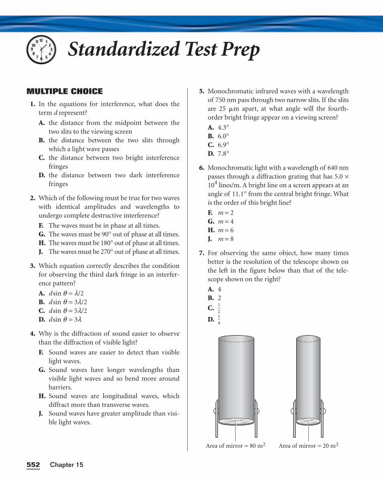
Standardized Test Prep
MULTIPLE CHOICE
1. In the equations for interference, what does theterm d represent?
A. the distance from the midpoint between thetwo slits to the viewing screen
B. the distance between the two slits throughwhich a light wave passes
C. the distance between two bright interferencefringes
D. the distance between two dark interferencefringes
2. Which of the following must be true for two waveswith identical amplitudes and wavelengths toundergo complete destructive interference?
F. The waves must be in phase at all times.G. The waves must be 90° out of phase at all times.H. The waves must be 180° out of phase at all times.J. The waves must be 270° out of phase at all times.
3. Which equation correctly describes the conditionfor observing the third dark fringe in an interfer-ence pattern?
A. d sin q = l/2B. d sin q = 3l/2C. d sin q = 5l/2D. d sin q = 3l
4. Why is the diffraction of sound easier to observethan the diffraction of visible light?
F. Sound waves are easier to detect than visiblelight waves.
G. Sound waves have longer wavelengths thanvisible light waves and so bend more aroundbarriers.
H. Sound waves are longitudinal waves, whichdiffract more than transverse waves.
J. Sound waves have greater amplitude than visi-ble light waves.
5. Monochromatic infrared waves with a wavelengthof 750 nm pass through two narrow slits. If the slitsare 25 �m apart, at what angle will the fourth-order bright fringe appear on a viewing screen?
A. 4.3°B. 6.0°C. 6.9°D. 7.8°
6. Monochromatic light with a wavelength of 640 nmpasses through a diffraction grating that has 5.0 ×10⁴ lines/m. A bright line on a screen appears at anangle of 11.1° from the central bright fringe. Whatis the order of this bright line?
F. m = 2G. m = 4H. m = 6J. m = 8
7. For observing the same object, how many timesbetter is the resolution of the telescope shown onthe left in the figure below than that of the tele-scope shown on the right?
A. 4B. 2
C. 12
D. 14
Area of mirror = 80 m2 Area of mirror = 20 m2
Chapter 15552
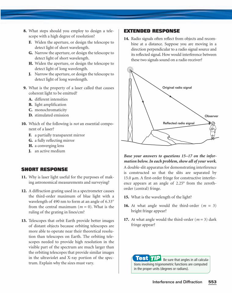
8. What steps should you employ to design a tele-scope with a high degree of resolution?
F. Widen the aperture, or design the telescope todetect light of short wavelength.
G. Narrow the aperture, or design the telescope todetect light of short wavelength.
H. Widen the aperture, or design the telescope todetect light of long wavelength.
J. Narrow the aperture, or design the telescope todetect light of long wavelength.
9. What is the property of a laser called that causescoherent light to be emitted?
A. different intensitiesB. light amplificationC. monochromaticityD. stimulated emission
10. Which of the following is not an essential compo-nent of a laser?
F. a partially transparent mirrorG. a fully reflecting mirrorH. a converging lensJ. an active medium
SHORT RESPONSE
11. Why is laser light useful for the purposes of mak-ing astronomical measurements and surveying?
12. A diffraction grating used in a spectrometer causesthe third-order maximum of blue light with awavelength of 490 nm to form at an angle of 6.33°from the central maximum (m = 0). What is theruling of the grating in lines/cm?
13. Telescopes that orbit Earth provide better imagesof distant objects because orbiting telescopes aremore able to operate near their theoretical resolu-tion than telescopes on Earth. The orbiting tele-scopes needed to provide high resolution in thevisible part of the spectrum are much larger thanthe orbiting telescopes that provide similar imagesin the ultraviolet and X-ray portion of the spec-trum. Explain why the sizes must vary.
EXTENDED RESPONSE
14. Radio signals often reflect from objects and recom-bine at a distance. Suppose you are moving in adirection perpendicular to a radio signal source andits reflected signal. How would interference betweenthese two signals sound on a radio receiver?
Base your answers to questions 15–17 on the infor-mation below. In each problem, show all of your work.
A double-slit apparatus for demonstrating interferenceis constructed so that the slits are separated by15.0 �m. A first-order fringe for constructive interfer-ence appears at an angle of 2.25° from the zeroth-order (central) fringe.
15. What is the wavelength of the light?
16. At what angle would the third-order (m = 3)bright fringe appear?
17. At what angle would the third-order (m = 3) darkfringe appear?
Observer
Original radio signal
Reflected radio signal
553Interference and Diffraction
Be sure that angles in all calcula-tions involving trigonometric functions are computedin the proper units (degrees or radians).
Chapter 15554
PROCEDURE
Preparation
1. Read the entire lab, and plan the steps you will take.
2. If you are not using a datasheet provided by your teacher, prepare a data
table in your lab notebook with six columns and four rows. In the first
row, label the columns Light Source, Image Color, Order, Image 1 (m),
Image 2 (m), and Slit (m). In the first column, label the second through
fourth rows White. Above or below the data table, prepare a space to
record the slit spacing, d, of the grating.
Wavelengths of White Light
3. Set up the optical bench as shown in Figure 1. Mount the scale and slit
on one end of the optical bench, and place a piece of tape over the slit.
Place a cardboard shield around the light source to direct all the light
through the slit. Illuminate the slit with white light. Mount the grating
near the opposite end of the optical bench.
4. Adjust the apparatus so that the white-light source is centered on the slit
and the slit scale is perpendicular to the optical bench. Tape the optical
bench and the white-light source securely in place.
In this experiment, you will pass white light through a diffraction grating and
make measurements to determine wavelengths of the light’s components.OBJECTIVE
•Discover wavelengths of diffracted light.
MATERIALS LIST• bent paper-clip riders for
meterstick• black cardboard• cellophane tape• diffraction grating• grating holder and support• incandescent light source and
power supply• meterstick and 2 supports• metric scale and slit
Skills Practice LabCHAPTER 15
Diffraction
SAFETY
• Avoid looking directly at a light source. Looking directly at a lightsource can cause permanent eye damage. Put on goggles.
• Use a hot mitt to handle resistors, light sources, and other equipmentthat may be hot. Allow all equipment to cool before storing it.
• If a bulb breaks, notify your teacher immediately. Do not remove bro-ken bulbs from sockets.
• Never put broken glass or ceramics in a regular waste container. Use adustpan, brush, and heavy gloves to carefully pick up broken pieces anddispose of them in a container specifically provided for this purpose.
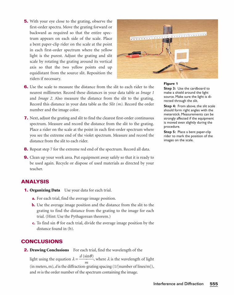
555Interference and Diffraction
5. With your eye close to the grating, observe the
first-order spectra. Move the grating forward or
backward as required so that the entire spec-
trum appears on each side of the scale. Place
a bent paper-clip rider on the scale at the point
in each first-order spectrum where the yellow
light is the purest. Adjust the grating and slit
scale by rotating the grating around its vertical
axis so that the two yellow points end up
equidistant from the source slit. Reposition the
riders if necessary.
6. Use the scale to measure the distance from the slit to each rider to the
nearest millimeter. Record these distances in your data table as Image 1
and Image 2. Also measure the distance from the slit to the grating.
Record this distance in your data table as the Slit (m). Record the order
number and the image color.
7. Next, adjust the grating and slit to find the clearest first-order continuous
spectrum. Measure and record the distance from the slit to the grating.
Place a rider on the scale at the point in each first-order spectrum where
you see the extreme end of the violet spectrum. Measure and record the
distance from the slit to each rider.
8. Repeat step 7 for the extreme red end of the spectrum. Record all data.
9. Clean up your work area. Put equipment away safely so that it is ready to
be used again. Recycle or dispose of used materials as directed by your
teacher.
ANALYSIS
1. Organizing Data Use your data for each trial.
a. For each trial, find the average image position.
b. Use the average image position and the distance from the slit to the
grating to find the distance from the grating to the image for each
trial. (Hint: Use the Pythagorean theorem.)
c. To find sin q for each trial, divide the average image position by the
distance found in (b).
CONCLUSIONS
2. Drawing Conclusions For each trial, find the wavelength of the
light using the equation l = d (s
m
inq), where l is the wavelength of light
(in meters, m), d is the diffraction-grating spacing (1/[number of lines/m]),
and m is the order number of the spectrum containing the image.
Figure 1Step 3: Use the cardboard tomake a shield around the lightsource. Make sure the light is di-rected through the slit.Step 4: From above, the slit scaleshould form right angles with themeterstick. Measurements can bestrongly affected if the equipment is moved even slightly during theprocedure.Step 5: Place a bent paper-cliprider to mark the position of theimages on the scale.


![- fisica [raymond serway] - para ciencias e ingenieria tomo ii.pdf](https://img.pdfslide.net/doc/110x75/55cf9a29550346d033a0afb0/-fisica-raymond-serway-para-ciencias-e-ingenieria-tomo-iipdf.jpg)


![Fisica [Raymond Serway] - Para Ciencias e Ingenieria Tomo II](https://img.pdfslide.net/doc/110x75/563db8b8550346aa9a964b91/fisica-raymond-serway-para-ciencias-e-ingenieria-tomo-ii.jpg)