Embed Size (px)
Citation preview
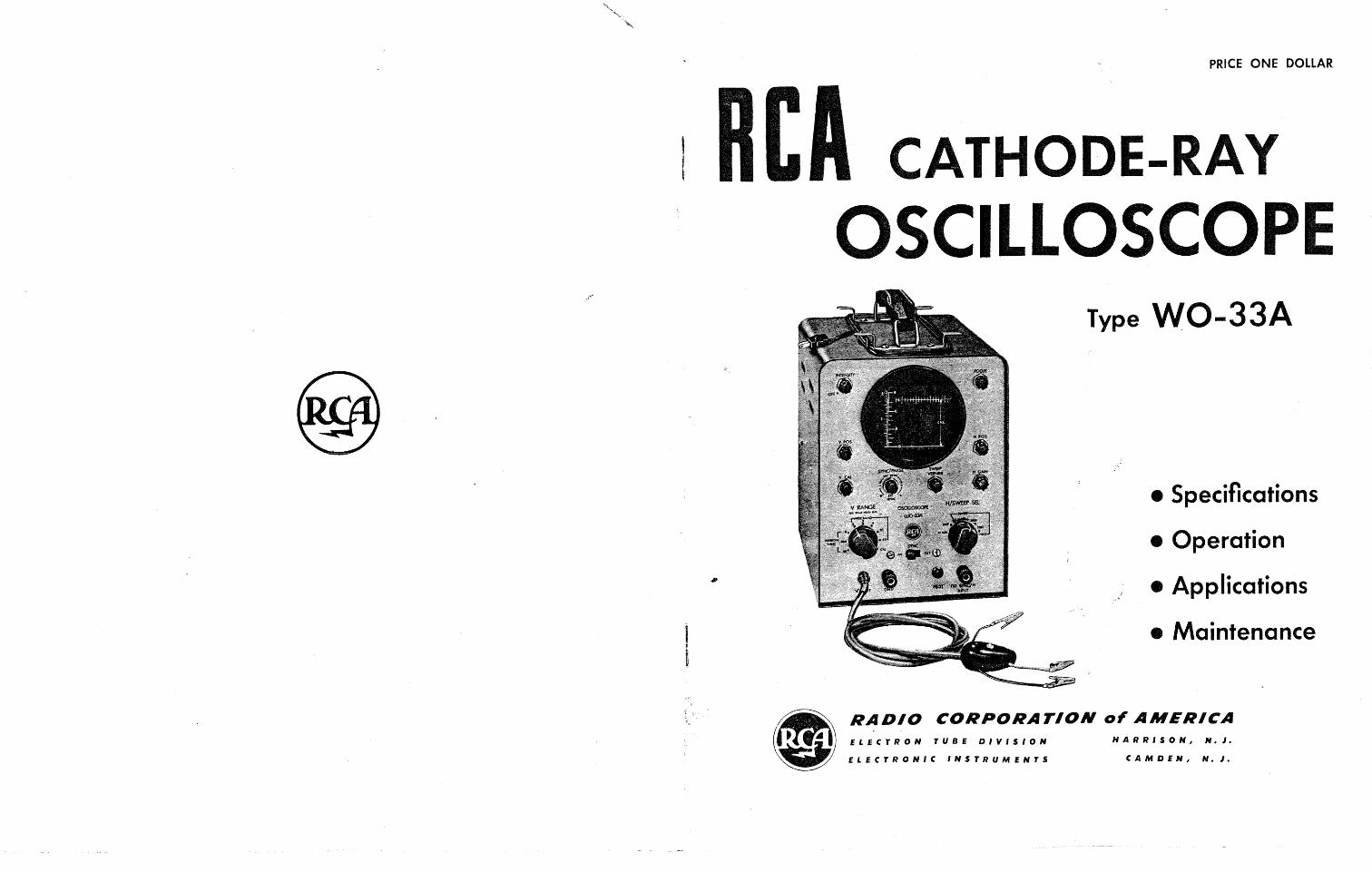
PRICE ONE DOLLAR
CATHODE-RAY OSCILLOSCOPE
Type WO-33A
• Specifications
• Operation
• Applications
• Maintenance
e) RADIO CORPORATION 0' AMERICA ~ .' ~l: ELECTRON TUBE OlVISION HARRISON, N.J.
~ ELECTRONIC INSTRUMENTS CAMDEN, N. J.
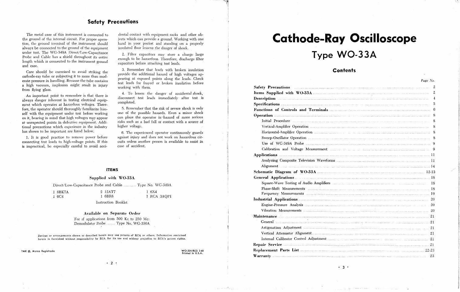
Safety Precautions
The metal case of this instrument is connected to the ground of the internal circuit. For proper operation, the ground terminal of the instrument should
. always be connected to the ground of the equipment under test. The WG-349A Direct/Low-Capacitance Probe and Cable has a shield throughout its entire length which is connected to the instrument ground and case.
Care should be exercised to avoid striking the cathode-ray tube or subjecting it to more than moderate pressure in handling. Because the tube contains a high vacuum, implosion might result in injury from flying glass.
An important point to remember is that there is always danger inherent in testing electrical equipment which operates at hazardous voltages. Therefore, the operator should thoroughly familiarize himself with the equipment under test before working on it, bearing in mind that high voltages may appear at unexpected points in defective equipme~t. Additional precautions which experience in the industry has shown to be important are listed below.
1. It is good practice to remove power before connecting test leads to high-voltage points. If this is impractical, be especially careful to avoid acci-
dental contact with equipment racks and other objects which can provide a ground. Working with one hand in your pocket and standing on a properly insulated Hoor lessens the danger of shock.
2. Filter capacitors may store a charge large enough to be hazardous. Therefore, discharge filter capacitors before attaching test leads.
3. Remember that leads with broken insulation provide the additional hazard of high voltages appearing at exposed points along the leads. Check test leads for frayed or broken insulation before working with them.
4. To lessen the danger of accidental shock, disconnect test leads immediately after test is completed.
.5. Remember that the risk of severe shock is only one of the possible hazards. Even a minor shock can place the operator in '-hazard of more serious risks such as a bad fall or contact with a source of higher voltage.
B. The experienced operator continuously guards against injury and does not work on hazardous circuits unless another person is available to assist in case of accident.
ITEMS
Supplied with WO-33A
Direct/Low-Capacitance Probe and Cable Type No. WG-349A
1 BX4 1 BBK7A 1 BC4
2 12AT7 1 BBR8
Instruction Booklet
Available on Separate Order
1 RCA 3AQPl
For rf applications from 500 Kc to 250 Mc: Demodulator Probe ........ Type No. WG-350A
Devices or arrangements shown or described herein may use patents of RCA or othet's. Information contained herein is furnished without responsibility by RCA for its use and without prejudice to RCA's patent rights.
TMK ®. Marco Registrodo
• 2 •
WQ-3]AIB(2) 3-60 Printed in U.S.A.
Cathode-Ray Oscilloscope Type WO-33A
Contents
Safety Precautions ......................................... .
Items Supplied with WO-33A
Description
Specifications
Functions of Controls and Terminals.
Operation
Initial Procedure
Vertical-Amplifier Operation
Horizontal-Amplifier Operation
Sweep-Oscillator Operation
Use of WG-349A Probe
Calibration and Voltage Measurement
Applications. . .............. .
Analyzing Composite Television Waveforms
Alignment
Schematic Diagram of WO-33A ...... .
General Applications ............ .
Square-Wave Testing of Audio Amplifiers ..
Phase-Shift Measurements Frequency Measurements ............................ ....... ..
Industrial Applications ........................... , ..
Engine-Pressure Analysis
Vibration Measurements
. Maintenance.
General
Astigmatism Adjustment
Vertical Attenuator Alignment .............. .
Internal Calibrator Control Adjustment...
Repair Service
Replacement Parts List.
Warranty
• 3 •
Page :\'/0,
2
2
5
6
8
8
8
8
8
9
9
..11
.......... 11
14
12-13
18
18
18 19
20
20
20
21
..... 21
21
21
21
... 21
22-2.3
23
Description
The RCA WO-33A is a 3-inch oscilloscope designed for "on-location" and service-shop use in servicing color and black-and-white television receivers, Hi-Fi equipment, PA and sound reenforcing systems,broadcast station and remote equipment, communications and industrial electronic equipment.
A novel feature of the WO-33A is the Vertical Input Attenuator which automatically switches the
amplifier from Wide Band to Narrow Band when in the three highest gain positions.
Another important feature of the WO-33A is
the exceptionally high gain in its vertical amplifier. There is enough sensitivity to provide a useful dis
play of signals from low-level microphones, phonopickups and other weak signals found in radio/TV
receivers, audio amplifiers, etc.
A voltage-calibrated, frequency-compensated vertical-input attenuator, an internal calibrating-voltage
source, and a graph screen scaled directly in volts
make it possible to use the WO-33A as a visual voltmeter. The unique system of calibrating the graph screen provides for scaling voltages directly
from the screen. The measurement procedure is very
similar to that employed with a vacuum-tube voltmeter. A calibrating voltage is automatically applied
to the vertical amplifier when the bandwidth control is set to the calibration position. This switch also disconnects internally the input and attenuator circuits,
making it unnecessary to remove leads and probes
from the external circuit under test. These unique facilities make voltage calibration and measurement a simple, almost automatic procedure.
The sweep-frequency control is continuously adjustable from 15 cps to 75 Kc. The sweep oscillator has excellent stability at high sweep rates, a fast retrace, and adequate linearity throughout its frequency range. The over-all frequency range of the oscillator is divided into four basic ranges; a vernier adjustment, which overlaps the basic sweep ranges, provides exact adjustment of the sweep frequency. The amount of sync signal fed to the sweep oscillator may be adjusted by means of a front-panel
• 4 •
control. Sweep synchronization is exceptionally stable throughout the sweep range of the oscillator.
A phase control is provided for varying the phase of the internal sweep voltage when the "LINE" position of the H/SWEEP SEL cOlltrol is used, en
abling the WO-33A to be phased with an external
line-frequency sweep oscillator.
To facilitate its use, the WO-33A is equipped with
a specially designed single-unit probe and input
cable. This accessory, the WG-349A DirectiLowCapacitance Probe and Cable, is provided with a blue
input lead and a yellow input lead. When the blue
input is used, the test signal is fed directly to the vertical-input terminal. When the yellow input is
used, a special high-impedance circuit in the probe
is connected in series with the test point and the 'scope. This high-impedance circuit presents an overall input resistance of 10 megohms and an input
capacitance of approximately 10 ppf to the test circuit. This feature reduces circuit-loading effects and permits use in circuits which would not function properly if loaded down by a conventional oscilloscope.
The WO-33A can be used to trouble-shoot and
signal trace all sections of both black-and-white
and color-TV receivers. The voltage-calibrating facilities, wide band-pass, and high-impedance input characteristics make possible observations and measurements of color-burst signals and othe'; critical, ,.
high-frequency waveshapes in circuits which are
sensitive to loading effects.
The size and weight of the WO-33A make it an
especially portable instrument, useful in such applications as industrial maintenance and trouble-shooting, general waveform analysis, adjustment of radio
receivers and transmitters, square-wave and general
testing of audio equipment, peak-to-peak voltage measurements, and observation of vacuum-tube characteristics. The WO-33A is a versatile and reliable instrument, well suited to applications which require a dependable oscilloscope.
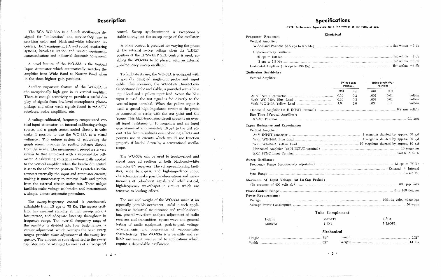
Specifications NOTE: Performance figures are for a line voltage of 117 volts, 60 cps.
Frequency Response: Electrical
Vertical Amplifier:
Wide-Band Positions (5.5 cps to 5.5 Mc) ..................................................... flat within - 3 db
High-Sensitivity Positions:
20 cps to 150 Kc ..................................................... .
3 cps to 1.5 Mc .................................................... .
Horizontal Amplifier (3.5 cps to 350 Kc)
Deflection Sensitivity:
Vertical Amplifier:
At V INPUT connector .......................................
With WG-349A Blue Lead With WG-349A Yellow Lead ..............
(Wide-Band) Positions
rms p-p
0.10 0.3 0.10 0.3 1.0 3.0
. ..... flat within - 3 db
flat within - 6 db
.... flat within - 6 db
(High-Sensitivity) Positions
rms p-p
.003 0.01 volt/in
.003 0.01 volt/in
.03 0.1 volt/in
Horizontal Amplifier (at H INPUT terminal)
Rise Time (Vertical Amplifier):
.......................................................................................... 0.9 rn1S volt/in
5.5-Me Positions 0.1 psec
Input Resistance and Capacitance:
Vertical Amplifier: At V INPUT connector ......................... ................. ............... ...................... 1 megohm shunted by approx. 50 f.Lpf
With WG-349A Blue Lead ...................... ....... ........ ........ ...... ... ... ...... 1 megohm shunted by apf)fox. 90 f.Lf.L f
\Vith \VG-349A Yellow Lead .................... . ................................. 10 megohms shunted by ap~rox. 10 pf.Lf
Horizontal Amplifier (at H INPUT terminal) .................................................... . ..... io megohms
EXT SYNC Input Terminal........................ . .................................................................... 250 K to 55 K
Sweep Oscillator:
Frequency Range (continuously adjustable)
Sync ................................... .
Sync Range.
Maximum AC Input Voltage (at Lo-Cap Probe):
(In presence of 400 volts dc) ............................ .
Phase-Control Range .............................................. .
Power Requirements:
Voltage .... Average Power Consumption .................................... .
1-6BR8
1-6BK7A
Tube Complement
2-12AT7
Height
Width
1-6X4
Mechanical
831f1 14
61111 12
• 5 •
Length
Weight
15 cps to 75 Kc
........................ External; ± Internal
... To 4.5 Mc
..... 600 p-p volts
o to 160 degrees
105-125 volts, 50-60 cps
. ........... 50 watts
1-6C4
1-3AQPl
....... lOW'
14 lbs
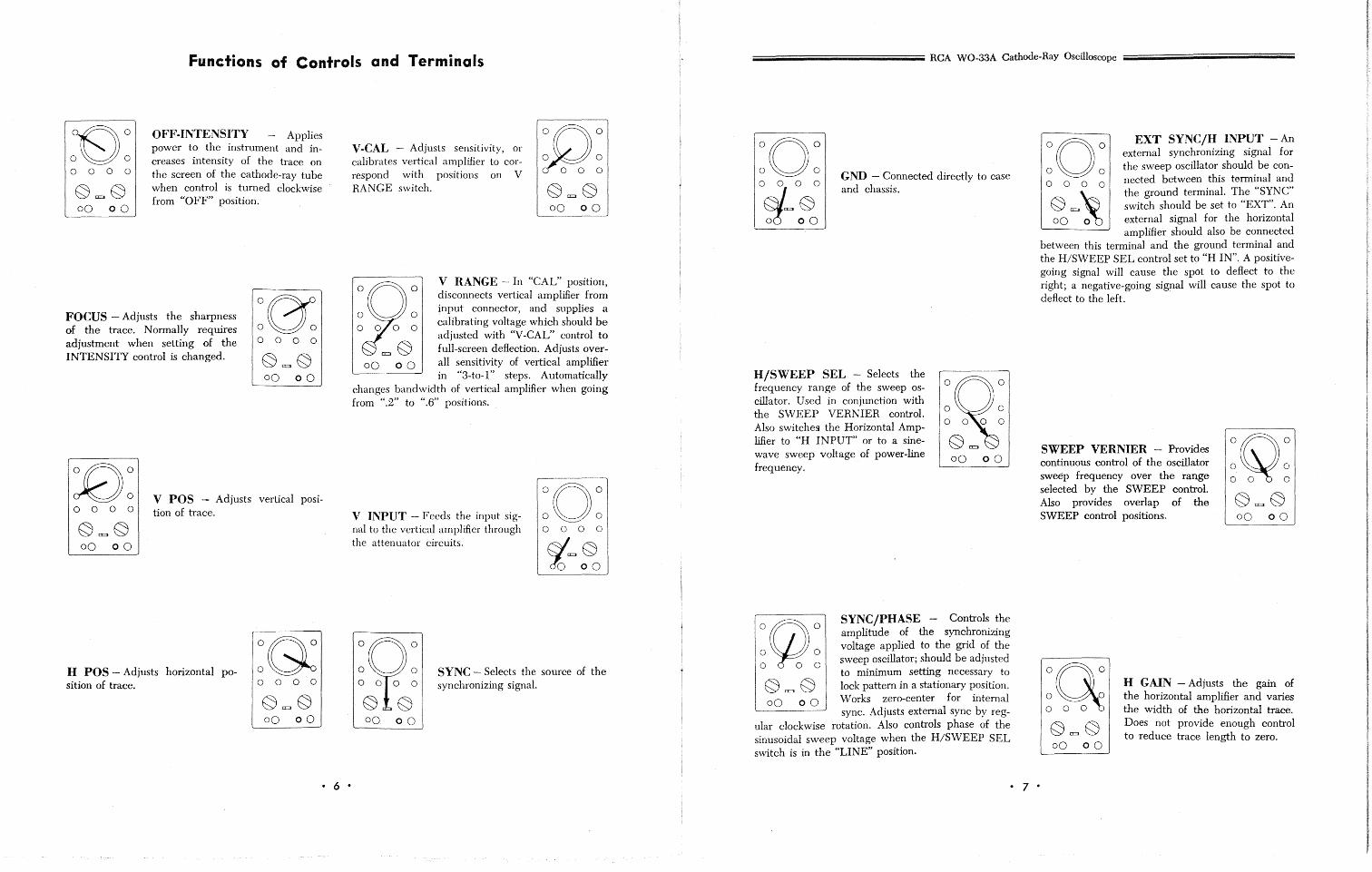
Functions of Controls and Terminals
o 0 0 0
E;)a=JE;) 00 00
OFF-INTENSITY - Applies power to the instrument and increases intensity of the trace on the screen of the cathode-ray tube when control is turned clockwise from "OFF" position.
FOCUS - Adjusts the sharpness of the trace. Normally requires adjustment when setting of the INTENSITY control is changed.
000 0
o 0 0 0 v POS - Adjusts vertical position of trace.
H POS - Adjusts horizontal position of trace. o 000
• 6 •
V-CAL - Adjusts sensitivity, or calibrates vertical amplifier to correspond with positions on V RANGE switch.
°n° O~O 000 0
E;)c=~
00 00
00 00
V RANGE - In "CAL" position, disconnects vertical amplifier from input connector, and supplies a calibrating voltage which should be adjusted with "V-CAL" control to full-screen deflection. Adjusts overall sensitivity of vertical amplifier in "3-to-l" steps. Automatically
changes bandwidth of vertical amplifier when going from ".2" to ".6" positions.
V INPUT - Feeds the input signal to the vertical amplifier through the attenuator circuits.
:0: 000 ° &c= ~ 'lac 00
SYNC - Selects the source of the synchronizing signal.
iiiiiiiiiiiiiiiiiiiiiiiiiiiiiiiiiiiiiiiiiiiiiiiiiiiiiiiiiiiiiiiiiiiiiiiiiiiiiiiiiiiiiiiiiiiiiiiiiiiiiiiiiiiiiiiiiiiiiiiiiiiii RCA WO-33A Cathode-Ray Oscilloscope iiiiiiiiiiiiiiiiiiiiiiiiiiiiiiiiiiiiiiiiiiiiiiiiiiiiiiiiiiiiiiiiiiiiiiiiiiiiiiiiiiiiiiiiiiiiiiiiiiiiiiiiiiiiiiiiii
:0: o~/=o~o ~c 00
GND - Connected directly to case and chassis.
H/SWEEP SEL - Selects the frequency range of the sweep oscillator. Used in conjunction with the SWEEP VERNIER control. Also switches the Horizontal AmpMer to "H INPUT" or to a sinewave sweep voltage of power-line frequency.
0(jJ}0 o 0 000 00 00
SYNC/PHASE - Controls the amplitude of the synchronizing voltage applied to the grid of the sweep oscillator; should be adjusted to minimum setting necessary to lock pattern in a stationary position. Works zero-center for internal sync. Adjusts external sync by reg
ular clockwise rotation. Also controls phase of the sinusoidal sweep voltage when the H/SWEEP SEL switch is in the "LINE" position.
• 7 •
:0: EXT SYNC/H INPUT - An external synchronizing signal for the sweep oscillator should be connected between this terminal and the ground terminal. The "SYNC" switch should be set to "EXT". An external signal for the horizontal amplifier should also be connected
between this terminal and the ground terminal and the H/SWEEP SEL control set to "H IN". A positivegoing signal will cause the spot to deflect to the right; a negative-going signal will cause the spot to deflect to the left.
SWEEP VERNIER - Provides continuous control of the oscillator sweep frequency over the range selected by the SWEEP controL Also provides overlap of the SWEEP control positions.
0QO o 0
000
0Q o 0 000
H GAIN - Adjusts the gain of the horizontal amplifier and varies the width of the horizontal trace. Does not provide enough control to reduce trace length to zero.
Operation
To become familiar with the operation of the WO-33A Oscilloscope, it is recommended that the operator follow the procedure outlined below in the order given. The section "Function of Controls and Terminals" on pages 6 and 7 of the block diagram on page 20 will also be helpful.
Initial Procedure
1. Connect the power cord at the rear of the instrument to an ac outlet supplying 105-125 volts at 50-60 cps.
2. Turn the INTENSITY control clockwise from the "OFF" position and wait a few seconds for the instrument to warm up.
3. Rotate the INTENSITY control farther clockwise until, either a spot or a horizontal line appears on the screen. The spot or line should increase in brilliance as the control is turned clockwise. NQTE: Do not allow a small spot of high brilliance to remain stationary on the screen for an appreciable length of time because discoloratiol'l or burning of the screen may result.
4. Adjust the FOCUS control for an image of maximum sharpness.
5. Turn the H/SWEEP SEL control to the "HIN" position. In this position, without an external signal being applied to the H-INPUT terminals, no sweep voltage, appears at the horizontal-deflecting electrodes of the cathode-ray tube and, therefore, only a spot will appea'r on the screen,
6. Position the spot in the center of the screen by adjusting the V POS and H POS controls.
Vertical-Amplifier Operation
1. Connect the WG-349A probe connector to the V INPUT connector, Set the V RANGE control to "CAL". The screen should now display a vertical trace, indicating that a signal has been applied to the vertical-deflecting electrodes of the cathode-ray tube.
2. Change the height of the vertical trace by rotating the V CAL control.
3. Set the H/SWEEP SEL to the dot between 15 and 150.
• 8 •
4. Lock in as described under "Sweep Oscillator Operation" .
Horizontal-Amplifier Operation
1. Apply an ac signal of from 1 to 3 volts to the EXT SYNC/H INPUT terminal. An audio-frequency generator or a 60-cps line signal may be used as the source. Set the HJSWEEP SEL to "H IN", set the V RANGE control to 60, and set the H GAIN control fully clockwise. A horizontal line will appear on the screen, indicating that an external signal has been applied to the horizontal-deflecting electrodes of the cathode-ray tube.
2. Disconnect the lead from the voltage source.
The horizontal line will be replaced by a spot.
3. Tum the H/SWEEP SEL to the "LINE" position. A horizontal line should appear. NOTE: When the H/SWEEP SEL switch is set to the "LINE" position, part of the power-line signal is fed internally to the horizontal amplifier, providing a sinusoidal horizontal-deflection voltage of power-line frequency. The SYNC/PHASE control can be nsed to adjust the phase of the internal sinusoidal sweep.
4. Turn the H/SWEEP SEL control to any of the sweep positions. The sawtooth output from the sweep oscillator is applied internally to the horizontal amplifier and a linear horizontal trace appears on the screen.
Sweep-Oscillator Operation
1. Adjust the H/SWEEP SEL and the SWEEP VERNIER control to give a sweep of approximately power-line frequency. Connect the ground lead from the WG-349A to the ground side of an ac-voltage source. An audio-frequency generator or a power-line signal can be used as a source. With the cable connector of the WG-349A attached to the V INPUT connector of the WO-33A, connect the blue lead to the other side of the low-voltage source. Adjust the SWEEP VERNIER control for a single cycle on the oscilloscope screen. Rotate the SYNC/ PHASE control and note that it should be adjusted to a minimum position neeessary to lock pattern in a stationary position.
iiiiiiiiiiiiiiiiiiiiiiiiiiiiiiiiiiiiiiiiiiiiiiiiiiiiiiiiiiiiiiiiiiiiiiiiiiiiiiiiiiiiiiiiiiiiiiiiiiiiiiiiiiiiiiiiiiiiiiiiiiiiiiii .. RCA WO-33A Cathode-Ray Oscilloscope
2. With a single pattern on the scr~n, notice whether the pattern drifts across the face of the tube. Horizontal drift indicates that the SYNC/PHASE control should be rotated toward its clockwise or counterclockwise limits or that the SWEEP VERNIER control should be adjusted until the waveform is locked in.
3. Connect the WG-349A connector to an external signal of a different frequency.
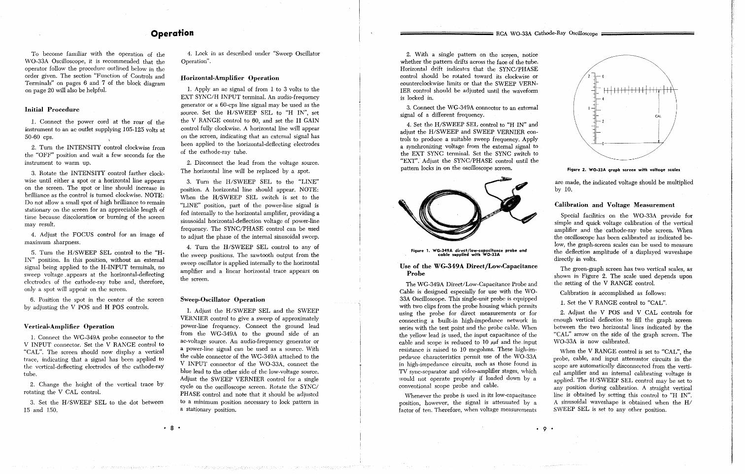
4. Set the H/SWEEP SEL control to «H IN" and adjust the H/SWEEP and SWEEP VERNIER controls to produce a suitable sweep frequency. Apply a synchronizing voltage from the external signal to the EXT SYNC terminal. Set the SYNC switch to "EXT".' Adjust the SYNC/PHASE control until the pattern locks in on the oscilloscope screen.
Figure 1. WG-349A direet/low-capacitance probe and cable supplied with WO-llA
Use of the WG-349A Direct/Low-Capacitance Probe
The WG-349A Direct/Low-Capacitance Probe and Cable is designed especially for use with the WO-33A Oscilloscope. This single-unit probe is equipped with two clips from the probe housing which permits using the probe for direct measurements or for connecting a built-in high-impedance network in series with the test point and the probe cable. When the yellow lead is used, the input capacitance of the cable and scope is reduced to 10 /L/Lf and the ,input resistance is raised to 10 megohms. These high-impeda'1ce characteristics permit use of the WO-33A in high-impedance circuits, such as those found in TV sync-separator and video-amplifier stages, which would not operate properly if loaded down by a conventional scope probe and cable.
Whenever the probe is used in its low-capacitance position, however, the signal is attenuated by a factor of ten. Therefore, when voltage measurements
• 9 •
Figure 2. WO·llA graph screen with voltage scales
are made, the indicated voltage should be multiplied by 10.
Calibration and Voltage Measurement
Special facilities on the WO-33A provide for simple and quick voltage calibration of the vertical amplifier and the' cathode-ray tube screen. When the oscilloscope has been calibrated as indicated below, the graph-screen scales can be used to measure the deflection amplitude of a displayed waveshape directly in volts.
The green-graph screen has two vertical scales, as shown in' Figure 2. The scale used depends upon the setting of the V RANGE control.
Calibration is accomplished as follows:
1. Set the V RANGE control to "CAL".
2. Adjust the V POS and V CAL controls for enough vertical deflection to fill the graph screen between the two horizontal lines indicated by the "CAL" arrow on the side of the graph screen. The WO-33A is now calibrated.
When the V RANGE control is set to "CAL", the probe, cable, and input attenuator circuits in the scope are automatically disconnected from the vertical amplifier and an internal calibrating voltage is applied. The H/SWEEP SEL control may be set to any position during calibration. A straight vertical line is obtained by setting this control to "H IN", A sinusoidal waveshape is obtained when the HI SWEEP SEL is set to any other position.
oOiiiiiiiiiiiiiiiiiiiiiiiiiiiiiiiiiiiiiiiiiiiiiiiiiiiiiiiiiiiiiiiiiiiiiiiiiiiiiiiiiiiiiiiiiiiiiiiiiiiiiiiiiiiiiiiiiiiiiiiiiiiiiiiiiiiiiiiiiiiiiiiiii RCA WO-33A Cathode-Ray Oscilloscope
Calibration will hold for both the wide band and narrow bandwidth positions. After calibration, an input signal may be read directly in peak-to-peak volts by measuring the vertical deflection against the correct graph-screen scale.
Example: It is desired to simultaneously display and measure the peak-to-peak voltage amplitude of the horizontal driving pulse at the grid pin of the horizontal-deflection-output stage in a TV receiver. Procedure is as follows:
1. Set the bandwidth control to "CAL" and set the H/SWEEP SEL to "H IN".
2. Adjust the V CAL control for exactly full scale vertical deflection as measured on the graph screen. Adjust the V POS control so that the bottom of the trace rests on the base-scale line and the top of the trace rests on the upper horizontal line.
3. The WO-33A is now calibrated.
4. Connect the ground lead from the WG-349A to the TV chassis. Connect the blue probe clip to the appropriate tube-socket pin.
5. Set the V RANGE control to a position which gives the desired on-screen deflection of the waveshape.
6. Lock in the waveshape as described under "Sweep Oscillator Operation".
7. Adjust the V POS control to position the bottom of the trace on the graph-screen base line.
8. Read the peak-to-peak voltage amplitude of the waveshape from the appropriate scale on the graphscreen. The peak-to-peak voltage is read from the scale point opposite the top of the waveshape.
NOTE: If the WG-349A is used in its low-capacitance position, an attenuation factor of 10 is introduced and it will, therefore, be necessary to multiply the voltage reading by 10 to obtain the correct peak-to-peak voltage amplitude.
• 10 •
Applications
Successful servICIng and maintenance of blackand-white and color-television receivers requires special techniques, not usually employed in the servicing of other electronic equipment. The general complexity and variety of circuits used in modem television receivers requires a great deal of knowledge on the part of the service technician and demands that test equipment be used properly.
The oscilloscope is of especial importance in the servicing of color receivers. A good television-service oscilloscope, such as the RCA WO-33A, may be u5ed in signal tracing in every section of the receiver; the 'scope may also be used for making peak-to-peak voltage measurements in such important sections of the receiver as the sync and deflection circuits and in the video, chrominance, and luminance sections of color-TV receivers. In alignment work, where video, chrominance, and luminance circuit adjustments must be made to produce the desired waveshape, the oscilloscope is indispensable. The WO-33A may be used in all these applications.
Signal-tracing means tracing the television signal through various sections of the television receiver to determine how circuits are functioning in terms of the shape and voltage value of the waveform. As the signal passes from one stage to another in the receiver, the shape of the waveform may be altered,
Fi9ure 3. Horizontal-sync pulse in composite signal
Fi9ure 4. Vertical-sync pulse In composite signal
• 11 •
and the height, or voltage amplitude of the waveform may be changed. Whenever possible, the WG-349A probe should be used in the "LOW CAP" position for signal tracing the video amplifier and chrominance circuits because of the low input capacitance and consequent negligible loading of the circuit under test. When the WO-33A is calibrated as described under "Operation", it is possible to simultaneously read the voltage value and observe the shape of the waveform. The process of signal tracing is thus speeded up and it is possible to ascertain a circuit condition quickly.
NOTE: The applications described here apply both to color and to black-and-white receivers.
Analyzing C~mposite Television Waveforms
Probably the most important waveform encountered in television service work is the composite video waveform consisting of the video signal, the blanking pedestals, and the sync pulses. Photographs of the composite video signal are shown in Figures 3 and 4. The photographs are oscilloscope traces, and show what the composite video signal looks like as it proceeds through the video amplifier of a television receiver.
The television service technician should devote some time to the study of such waveforms by setting up a television receiver known to be in goodoperating condition and noting the waveforms on the WO-33A at various points in the video amplifier. Traces similar to those shown in Figures 3 and 4 may be obtained on the WO-33A as follows:
(Continued on page 14)
NORMAL fl, .. SYNC PULSE J •
SYNC PULSE ~ COMPRESSION
CAUSED BY JJ LIMITING 'it'
"WHITE" ' l SATURATION CAUSED BY
LIMITING ~
Figure 5. Sync-pulse compression
R66 22K
SI#W+
~ -~ I38c 220V
20IJF ®c V "RANGE -= 0-- 1'\11
iJC8 0--
SK
22 0------
51,'6'2 0---
RI2 8.2K
GNO (lM.ACK)
V INPUT C2
R65 ,2801{ 2 SK
SI,l('V3
1 C38B'--1 20}JF
<>--
0-
~
<>-
0-
R80 820i'(\-
I I
l~~FI - I
"
:.~9KI II <>---+--~ J J
ilfFS~~~1
o-&i. <>------
R67 C I .2 4-4 0 O---r-~---1f---,
GND. ®., ~+---~~~+-------------~
-= o-L
EO
20
GO r-"
OtAL r---:- p-- ~ t--RI
~b. R3 R4 6sa< 1M 1M
; 47K
j ~ LI .~ 20JJH
RI5
cw VI 12K CI4 6BR8A .I.OV
O.l)JF 175V
~ r.L -~ ~ H '-~~ ",w,>'----
R5 __
RI8 1.2K
tel8 .1 )JF
C5 ~ 'C6 Y' 15K RI3 IJV e 3I-!:.r.e"-'v'--__ ~
EXT HI
S3
C~l-4-40 <2>
~~ 470K
$:9 64
~=-
C4 if . 4-46~ ~r HO~
CIO 140
440 0 4-40 0 T ~~ ~t-
33K~" . 10K
410 1CI2 ISOO
RIO 820
.---------4= RS~A
1M
CI3 1200
R 14 100 CIS +
.02JJF C38A 10}JF
: R42 cw R44
V 3: lOOK 270K 12AT:7 150V t-'s"'"'S.!..v __________ --, __ --,
Al~ 5,22 tNT ~2)JF
!? I
5 IF---EXT~
cw R39 :1....... _l)~ R758 I 68K U [r-----, 250K ::>+-T'-'-"brvv'v --.--.,n .... - -- - - - 2 ~ J.-.o
115n'C~PHAs(1 C 23 : \....... ] 0 0 0 0
C21 .02JJF 3
ff,-- ,,~s :~ I ~~c I ·.----,.6..-V--"''Q9()() I ~@? I
S,------1
' o-,~~r> R41', ~~
R40 3.3K
680 ""lrCW
R438 s2,jW.3 S2,W2. ~ fSz,W/l-vi~~f:R 1M .~ C29 ~
H/SWEEP SEL.
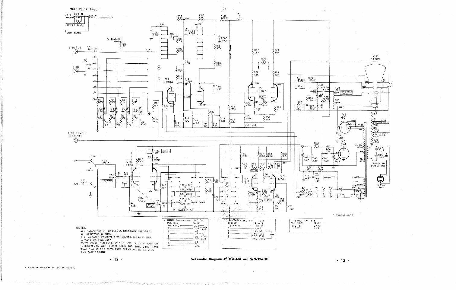
NOTES ALL CAPACITQRS IN )J)JF, UNLESS OTHERWISE SPECIFIED. ALL RESISTQRS IN OHMS. ALL VQLTAGES POSIT! 'IE fROM GROUND, AND MEASURED .'WITH A VOLTOHMYSr-
S\-1ITCHES S-I AND S-2 SHO'WN IN MAXIMUM CCW POSITIQN
.INSTRUMENTS 'WITH SERIAL NO:S fOOl THRU 2300 HAVE TWO. .0.01 MF DISC CAPACITORS BETWEEN THE AC LINE AND C1\SE GROUND
V RANGE FULL 'SCALE VOLTS (p-p) S-I PQSIT ION RANGE I (ccw M.'-x) 0.0.2--'-, 2' 0..06 N~~~~W 3 0.2 ----' 4 0..6, 5 2.0. WIDE
6 6.0 SAND
~ ~g.-.J 9 CAL
R 16 I~
R 17 120
CI6 S60
I I ! !
~R22 1220K
1
~R23 182K
1
\ \
3~1{
R32 1.8K
R26 10K
1, f I R31 1.2K
q 250V
~ .... V2 7 6BK7 ---
r-- IY::::ITiJ '- R27
eOI{ SK R20 8 470K Cwt:.J
R29 IK
R21 R30 470K 2.4K
CI7 .I}JF
12 • Schematic Dia9ram ef WO-33A and WO.l3A(K)
• TRAD(-MARK "VOLTOHMYST" REG. u.s. PAT. OFF.
I
R24 1.8K
R25 1.2K
~250V ------~ -I( eo~ a
R28 ~ I K
L2 36 H
CI9 .05)JF
10K
10K,
L3 :r6)JH
~~t3 R34 Iv posl 820K
~w, R35
,¥ 1M R37 R36 820K 1.2M
-= C20 R38 .05.!JF 1M
R74 R75A 120K 25PK
EJ-V
V6 6C4
V-El.-RO. 32SVAC
RD. 325\1A
C42 ISYNC/PHASEI X6~ .I)JF 6.3VAC
GRN."YEL~ x __ cw VI V2 VS V3 V4 BLU-YEI.
4 5 3
~5 ~VAC i.~ 5 4 4
4 :.T. n '~LU.
C33 .1 )JF
E-256616 -8-59
SYNC. SW. S-3 PQ'S IT 10 N RANGE
RIGHT EXT. LEFT INT.
13 •
V7 3AQPI
R78 ISK
R71 ~ov 500K
R70 470K ~
I r-=sR'----'t.:r-C
-3
-7
- -
, .OIJJF
tC36-~ SR T.o I,UF-=
POWER sW. (PART OF 1\ 73)
~ 117VAC 60--
iiiiiiiiiiiiiiiiiiiiiiiiiiiiiiiiiiiiiiiiiiiiiiiiiiiiiiiiiiiiiiiiiiiiiiiiiiiiiiiiiiiiiiiiiiiiiiiiiiiiiiiiiiiiiiiiiiiiiiiiiiiiiiiiii RCA W0-33A Cathode-Ray Oscilloscope iiiiiiiiiiiiiiiiiiiiiiiiiiiiiiiiiiiiiiiiiiiiiiiiiiiiiiiiiiiiiiiiiiiiiiiiiiiiiiiiiiiiiiiiiiiiiiiiiiiiiiiiiiiiiiiiiiiiiiiiiiiiiiiiiii
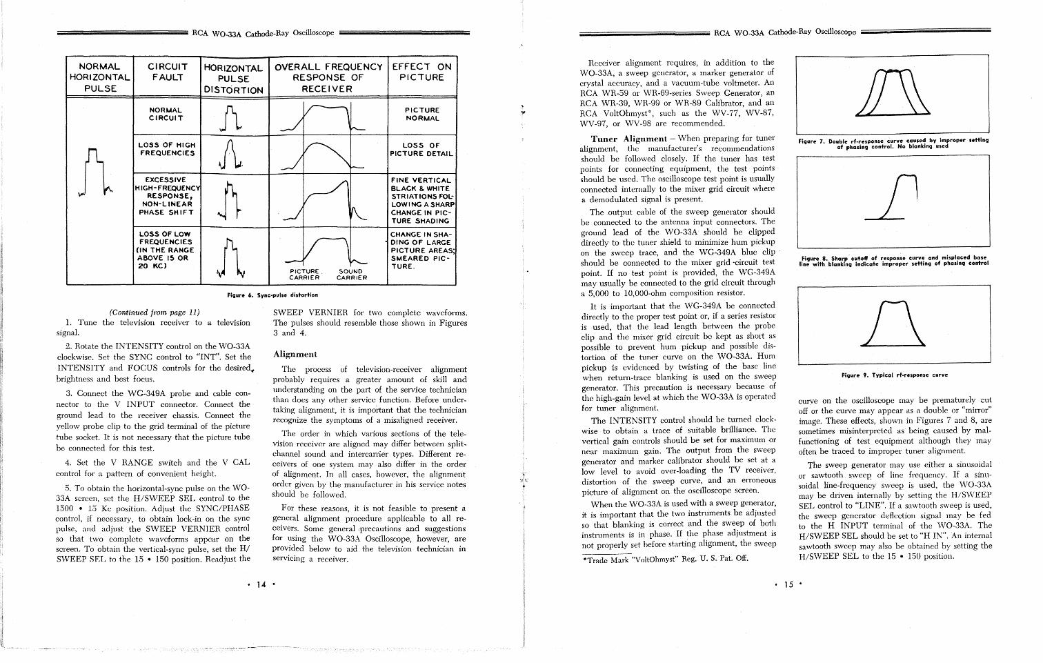
NORMAL CIRCUIT HORIZONTAL OVERALL FREQUENCY EFFECT ON HORIZONTAL FAULT PULSE RESPONSE OF PICTURE
PULSE DISTORTION RECEIVER
J\ V 1 NORMAL PICTURE CIRCUIT
~ NORMAL
r-
1\ LOSS OF HIGH A. ~
LOSS OF FREQUENCIES
--.I PICTURE DETAIL
I--
EXCESSIVE
J) V FINE VERTICAL
HIGH - FREQUENCY BLACK & WHITE RESPONSE, STRIATIONS FQL-
NON-LINEAR LOW I NG A SHARP PHASE SHIFT --l "'- CHANGE IN PIC-
TURE SHADING
LOSS OF LOW CHANGE IN SHA-FREQUENCIES
1\ V 1 DING OF LARGE (IN THE RANGE PICTURE AREAS; ABOVE 15 OR - I-"'- SMEARED PIC-20 KC) TURE.
PICTURE SOUND CARRIER CARRIER
Figure 6. Sync-pulse distortion
(Continued from page 11) 1. Tune the television receiver to a television
signal.
2. Rotate the INTENSITY control on the WO-33A clockwise. Set the SYNC control to "INT". Set the INTENSITY and FOCUS controls for the desiredof brightness and best focus.
3. Connect the WG-349A probe and cable connector to the V INPUT connector. Connect the ground lead to the receiver chassis. Connect the yellow probe clip to the grid terminal of the picture tube socket. It is not necessary that the picture tube be connected for this test.
4. Set the V RANGE switch and the V CAL control for a pattern of convenient height.
5. To obtain the horizontal-sync pulse on the WO-33A screen, set the H/SWEEP SEL control to the 1500 • 15 Kc position. Adjust the SYNC/PHASE control, if necessary, to obtain lock-in on the sync pulse, and adjust the SWEEP VERNIER control so that two complete waveforms appear on the screen. To obtain the vertical-sync pulse, set the HI SWEEP SEL to the 15 • 150 position. Readjust the
SWEEP VERNIER for two complete waveforms. The pulses should resemble those shown in Figures 3 and 4.
Alignment
The process of television-receiver alignment probably requires a greater amount of skill and understanding on the part of the service technician than does any other service function. Before undertaking alignment, it is important that the technician recognize the symptoms of a misaligned receiver.
The order in which various sections of the television receiver are aligned may differ between splitchannel sound and intercarrier types. Different receivers of one system may also differ in the order of alignment. In all cases, however, the alignment order given by the manufacturer in his service notes should be followed.
For these reasons, it is not feasible to present a general alignment procedure applicable to all receivers. Some general precautions and suggestions for using the WO-33A Oscilloscope, however, are provided below to aid the television technician in servicing a receiver.
• 14 •
iiiiiiiiiiiiiiiiiiiiiiiiiiiiiiiiiiiiiiiiiiiiiiiiiiiiiiiiiiiiiiiiiiiiiiiiiiiiiiiiiiiiiiiiiiiiiiiiiiiiiiiiiiiiiiiiiiiiiiiiiiiii RCA WO-33A Cathode-Ray Oscilloscope iiiiiiiiiiiiiiiiiiiiiiiiiiiiiiiiiiiiiiiiiiiiiiiiiiiiiiiiiiiiiiiiiiiiiiiiiiiiiiiiiiiiiiiiiiiiiiiiiiiiiiiiiiiiiiiiiiiiiiiiiiiiii
Receiver alignment requires, in addition to the WO-33A, a sweep generator, a marker generator of crystal accuracy, and a vacuum-tube voltmeter. An RCA WR-59 or WR-69-series Sweep Generator, an RCA WR-39, WR-99 or WR-89 Calibrator, and an RCA VoltOhmyst"', such as the WV-77, \VV-87, WV-97, or WV-98 are recommended.
Tuner Alignment - When preparing for tuner alignment, the manufacturer's recommendations should be followed closely. If the tuner has test points for connecting equipment, the test points should be used. The oscilloscope test point is usually connected internally to the mixer grid circuit where a demodulated signal is present.
The output cable of the sweep generator should be connected to the antenna input connectors. The ground lead of the W 0-33A should be clipped directly to the tuner shield to minimize hum pickup on the sweep trace, and the WG-349A blue clip should be connected to the mixer grid -circuit test point. If no test point is provided, the WG-349A may usually be connected to the grid circuit through a 5,000 to 10,000-ohm composition resistor.
It is important that the WG-349A be connected directly to the proper test point or, if a series resistor is used, that the lead length between the probe clip and the mixer grid circuit be kept as short as possible to prevent hum pickup and possible distortion of the tuner curve on the WO-33A. Hum pickup is evidenced by twisting of the base line when return-trace blanking is used on the sweep generator. This precaution is necessary because of the high-gain level at which the WO-33A is operated for tuner alignment.
The INTENSITY control should be turned clockwise to obtain a trace of suitable brilliance. The vertical gain controls should be set for maximum or near maximum gain. The output from the sweep generator and marker calibrator should be set at a low level to avoid over-loading the TV receiver, distortion of the sweep curve, and an erroneous picture of alignment on the oscilloscope screen.
When the WO-33A is used with a sweep generator, it is important that the two instruments be adjusted so that blanking is correct and the sweep of both instruments is in phase. If the phase adjustment is not properly set before starting alignment, the sweep
0Trade Mark "VoltOlunyst" Reg. U. S. Pat. Off.
Fi9ure 7. Double rf-response curve caused by improper settinq of phasin9 control. No blanking used
Figure 8. Sharp' cutoff of response curve and misplaced base line with blanking indicate improper settin9 of phasin9 control
Figure 9. Typical rf-response curve
curve on the oscilloscope may be prematurely cut off or the curve may appear as a double or "minor" image. These effects, shown in Figures 7 and 8, are sometimes misinterpreted as being caused by malfunctioning of test equipment although they may often be traced to improper tuner alignment.
The sweep generator may use either a sinusoidal or sawtooth sweep' of line frequency. If a sinusoidal line-frequency sweep is used, the WO-33A may be driven internally by setting the H/SWEEP SEL control to "LINE". If a sawtooth sweep is used, the sweep generator deflection signal may pe fed to the H INPUT terminal of the \i\10-33A. The H/SWEEP SEL should be set to "H IN". An internal sawtooth sweep may also be obtained by setting the H/SWEEP SEL to the 15 • 150 position.
• 15 •
;;;;;;;;;iiiiiiiiiiiiiiiiiiiiiiiiiiiiiiiiiiiiiiiiiiiiiiiiiiiiiiiiiiiiiiiiiiiiiiiiiiiiiiiiiiiiiiiiiiiiiiiiiiiiiiiiiiiiii RCA WO-33A Cathode-Ray Oscilloscope ;;;;;;;;;iiiiiiiiiiiiiiiiiiiiiiiiiiiiiiiiiiiiiiiiiiiiiiiiiiiiiiiiiiiiiiiiiiiiiiiiiiiiiiiiiiiiiiiiiiiiiiiiiiiiiiiiiiiiii
If no blanking is used, the SYNC/PHASE control should be adjusted until the two response curves coincide on the oscilloscope screen. If blanking is used, the SYNC/PHASE control should be adjusted until the base line on the WO-33A screen extends the full width of the curve trace. An extremely sharp drop-off point on the response curve, which gives a "chopped-off" appearance to the trace short of the end of its sweep range, also indicates improper phasing. When a marker is superimposed on the response curve, improper phasing will cause two markers to appear on the curve. The SYNC/PHASE control should be adjusted to obtain the appearance of a single trace having only one marker. The setting of the SYNC/PHASE control is also important during sweep alignment of other sections of the receiver.
Serious misalignment of the tuner or considerable difficulty or failure in alignment may be caused by an unsuspected defective component. If proper alignment procedure fails to produce correct tuner curves, the technician should check individual components in the rf unit.
Picture-IF Alignment - To obtain an over-all picture-if response curve, the blue clip of the WG-349A probe should be connected across either the second detector load resistor or to the grid of the first video stage; test points which can provide a demodulated signal to the oscilloscope. The ground lead should be connected to the chassis. Because of the additional amplification in this section of the receiver, the oscilloscope gain should be considerably reduced, but not to. the point where it is necessary to increase sweep-generator output.
Depending upon manufacturer's recommendations, it may be necessary to adjust the agc bias level, either through temporary wiring changes or by providing fixed battery bias. The service-notes should be followed closely because alignment procedure may involve considerable detail. Trap alignment is sometimes difficult because the marker disappears in the trap notch. This may often be overcome by magnifying the trap section of the trace with the V CAL and H GAIN controls.
Adjustment of the SYNC/PHASE control is also important when aligning the i-f sections of the receiver. The precautions and recommendations described under the section on tuner alignment, above, should be observed here. Controls on the WO-33A
should be set the same as for tuner alignment except that less vertical gain will be required.
For observation of the response of individual stages in the picture-if amplifier, the WG-350A Demodulator Probeo should be used. This is a highfrequency rectifying-type probe. It is important that this probe be used properly and in accordance with service-note recommendations to prevent distortion of the response curve and an erroneous picture of alignment.
The WG-350A, which connects to the V INPUT of the WO-33A, is equipped with a short ground lead and clip. For alignment work, the ground clip of the probe should always be connected to ground near the test point being used for the WG-350A.
When the WG-350A is used to check individual stages, it should be connected on the output side of the stage being adjusted. For example, if the alignment of a coupling transformer is to be checked, the probe should be connected to the plate of the tube which has its grid coupled to the transformer. The tube thus acts as a buffer between the high-impedance grid circuit and the probe.
For general signal-tracing work, the probe may be moved from grid to grid throughout the i-f amplifier.
Figure 10. (A) Ratio-detector curve and (8) sound-if curve
Sound-IF and Detector Alignment - Most television receivers use either a discriminator or ratio detector. For either type, the WG-349A probe clip should be connected to the output of the sound detector. F or detector alignment, the sweep and marker generators should be connected to the receiver as described in the service notes. An S-shaped curve, similar to that shown in Figure lOA, should be obtained on the oscilloscope screen. The setting of controls on the WO-33A should remain the same as before. A typical sound-if curve is shown in Figure
° Available on separate order.
• 16 •
;;;;;;;;;iiiiiiiiiiiiiiiiiiiiiiiiiiiiiiiiiiiiiiiiiiiiiiiiiiiiiiiiiiiiiiiiiiiiiiiiiiiiiiiiiiiiiiiiiiiiiiiiiiiiiiiiiiiiiiiiii RCA WO-33A Cathode-Ray Oscilloscope ;;;;;;;;;iiiiiiiiiiiiiiiiiiiiiiiiiiiiiiiiiiiiiiiiiiiiiiiiiiiiiiiiiiiiiiiiiiiiiiiiiiiiiiiiiiiiiiiiiiiiiiiiiiiiiiiiiiiiii
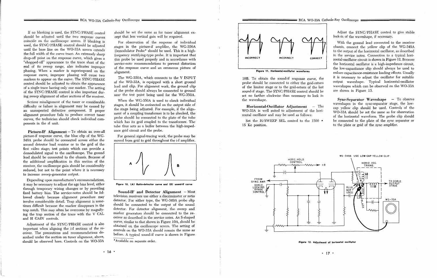
INCORRECT INCORRECT CORRECT
Figure 11. Horizontal-oscillator waveforms
lOB. To obtain the sound-if response curve, the probe should be connected to either the grid-return of the limiter stage or to the grid-return of the last sound-if stage. The SYNC/PHASE control should be set no farther clockwise than necessary to lock in the waveshape.
Horizontal-Oscillator Adjustment - The WO-33A is well suited to adjustment of the horizontaloscillator and may be used as follows:
Set the WSWEEP SEL control to the 1500 • 15 Kc position.
HORIZ. HOLD CONTROL
Adjust the SYNC/PHASE control to give stable lock-in of the waveshape, if necessary.
With the ground lead connected to the receiver chassis, connect the yellow clip of the WG-349A to the output of the horizontal oscillator, as described in the service notes. Connection to a typical horizontal-oscillator circuit is shown in Figure 12. Because the horizontal oscillator is a high-impedance circuit, the low-capacitance clip should always be used to reduce capacitance-resistance loading effects. Usually it is necessary to adjust the oscillator for suitable output waveshape. Typical horizontal-oscillator waveshapes which can be observed on the WO-33A are shown in Figure 13.
Sync-Separator· Waveshape - To observe waveshapes in the sync-separator stage, the lowcap yellow clip should be used. Controls of the WO-33A should be set the same as for observation of the horizontal waveform. The probe clip should be connected to the plate of the sync separator or to the plate or grid of the sync amplifier.
WG -349A USE LOW'CAP YELLOW CLIP
HORIZ.OSC. TRANS.
S-----I .--------<~ tt \
FROM ....I-----k I SYNC. AMP. TO HORIZ.
H 0 R I Z. ..-----<>---H--+---------40 1.....,...,4-+.4~.....,...)("")(""'IrI: ........ ___4_ 0 U T PUT LOCKING STAGE
RANGE CONTROL
I I Figure 12. Adiustment of horizontal oscillator
• 17 •
WO-33A
o
iiiiiiiiiiiiiiiiiiiiiiiiiiiiiiiiiiiiiiiiiiiiiiiiiiiiiiiiiiiiiiiiiiiiiiiiiiiiiiiiiiiiiiiiiiiiiiiiiiiiiiiiiiiiiiiiiiiii RCA WO-33A Cathode-Ray Oscilloscope
Figure 13. Color.TV signals as displayed by WO·33A. (A) Com. posite eolor·TV signal. Color-burst ean be seen to left of syne pulse. (B) Output signal from RCA WR-61A Color-Bar Generator
showing color-sync pulses and 10 color-bar pulses.
General Applications
Square-Wave Testing of Audio Amplifiers
The use of square waves for testing the characteristics of audio equipment has distinct advantages over other methods. A square-wave generator and the WO-33A Oscilloscope, when set up as shown in Figure 14, can provide a quick and accurate means of checking an amplifier and its adjustments. In this test setup, it is possible to check simultaneously the amplitude, phase, and frequency characteristics of the amplifier.
The value of the load resistance used depends upon the output impedance of the amplifier. It is important that the correct value be used. For an over-all check of amplifier response, the WO-33A should be connected directly across the load resistance, as shown.
It is desirable to employ square waves of at least two fundamental frequencies. The lowest fundamental frequency should be equal to approximately ten times the low-frequency limit of the amplifier being tested. A 100-cycle square wave should serve to check response from a few cycles to over 1000. If a square wave having a fundamental frequency of 2 Kc is used, the amplifier may be checked through the balance of the audible range.
The square-wave generator should be set to the proper frequency and connected to the regular input terminal of the amplifier. The WO-33A may be connected temporarily directly across the generator for a reference check of the waveform. The WO-33A may then be connected to various points in the amplifier to determine how each stage is functioning. The effect of various adjustments may be seen on the screen.
Care should be taken to prevent too large a signal from the square-wave generator from overloading the amplifier and causing distortion of the square wave.
Phase-Shift Measurements
To measure the phase shift of an audio network, apply a sine wave to the circuit under test and connect the direct probe to the output terminal of the network. This test signal should also be fed to the oscilloscope through the H INPUT and GND terminals. Set the H/SWEEP SEL control to the "H IN" position. If no phase shift exists, a sloping straight line will appear. Phase shift is indicated as an elliptical or circular trace. The method of calculating the degree of phase shift is shown graphically in Figure 16.
SQUAREWAVE
GENERATOR
AUDIO AMPLIFIER LOAD
YELLOW NOT USED
WG-349A
FICJure 14. Audio amplifier test setup
• 18 •
iiiiiiiiiiiiiiiiiiiiiiiiiiiiiiiiiiiiiiiiiiiiiiiiiiiiiiiiiiiiiiiiiiiiiiiiiiiiiiiiiiiiiiiiiiiiiiiiiiiiiiiiiiiiiiiiiiiiiiiiii RCA WO-33A Cathode-Ray Oscilloscope
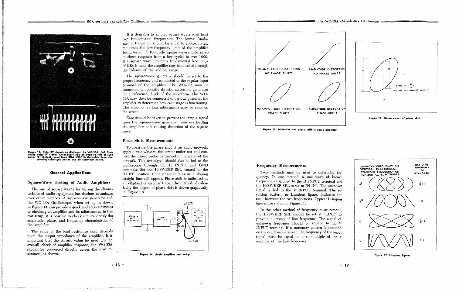
/ / NO AMPLITUDE DISTORTION AMPLITUDE DISTORTION
NO PHASE SHIFT NO PHASE SHIFT
C 0 NO AMPLITUDE DISTORTION AMPLITUDE DISTORTION
PHASE SHIFl PHASE SHIFT
Figure 15. Distortion and phase. shift in audio amplifier
Frequency Measurements
Two methods may be used to determine frequency. In one method, a sine wave of known frequency is applied to the H INPUT terminal and the H/SWEEP SEL is set to "H IN". The unknown signal is fed to the V INPUT terminal. The resulting pattern, or Lissajous figure, indicates the ratio between the two frequencies. Typical Lissajous figures are shown in Figure 17.
In the other method of frequency measurement, the H/SWEEP SEL should be set at "LINE" to provide a sweep of line frequency. The signal of unknown frequency should be applied to the V INPUT terminal. If a stationary pattern is obtained on the oscilloscope screen, the frequency of the input signal must be equal to, a submultiple of, or a multiple of the line frequency.
.. 19 •
r A
SINE cp = ~ • [ WHERE cp = PHASE ANGLE
0
Figure 16. Measurement of phase shift
UNKNOWN FREQUENCY ON VERTICAL ELECTRODES; STANDARD FREQUENCY ON HORIZONTAL ELECTRODES
RATIO OF UNKNOWN
TO STANDARD.
D 6:1
Figure 17. Llssalous fiCJures
PR ESS URE TRANSDUCER INSERTED IN
CYLINDER CHAMBER
iiiiiiiiiiiiiiiiiiiiiiiiiiiiiiiiiiiiiiiiiiiiiiiiiiiiiiiiiiiiiiiiiiiiiiiiiiiiiiiiiiiiiiiiiiiiiiiiiiiiiiiiiiiiii RCA WO-33A Cathode-Ray Oscilloscope· iiiiiiiiiiiiiiiiiiiiiiiiiiiiiiiiiijiiiiii, iiiiiiiiiiiiiiiiiiiiiiiiiiiiiiiiiiiiiiiiiiiiiiiiiiiiiiiiiiiiiiiiiiiiiiiiiiiiiiiii
VH~RATION PICKUP
Figure 18. ElIglne-pressure analysis setup
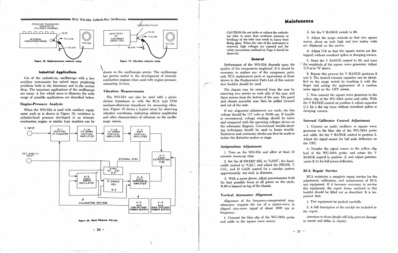
Industrial Applications
Use of the cathode-ray oscilloscope with a few auxiliary instruments has solved many perplexing problems both· in the laboratory and iu;the service shop. The important applications of the oscilloscope are many. A few which serve to illustrate the wide range of possible applications are described below.
Engine-Pressure Analysis
When the WO-33A is used with auxiliary equipment such as is shown in Figure 18, variations in cylinder-head pressure developed in an intemalcombustion engine or similar type machine can be
V INPUT S-\ V -\A
- VERTICAL ~
1/2 6BR8A ATTENUATOR VERTICAL
AMPLIFiER
I'
EXT SYNC / H INPUT
L • V-3
12AT7 ~ SWEEP
OSCILLATOR
-I
MACHINERY OR
EQUIPMENT UNDER TEST
"
Figure 19. Vibration analysis setup
\shown on the oscilloscope screen. The oscillosmpe has proven useful in the development of internalcombustion engines when used with engine pressuremeasuring devices.
Vibration Measurements
The WO-33A can also be used with a piezoelectric transducer or with the RCA type 5734 mechano-electronic transducer for measuring vibration. Figure 19 shows a typical setup for observing vibration waveforms, indicating relative amplitudes and other characteristics of vibration on the oscilloscope screen.
V-IB V-2
~ 1/2 6BR8A
~ 6BK7
VERTICAL VERTICAL AMPLIFIER AMPLIFIER
Ii
V-7 3AQPI ~ INTERNAL SYNC CATHODE RAY
j I TUBE
SYNC J
- INT EXT S-3
Y-4
!- ~ H / SWEEP ~ 12AT7
HORIZONTAL
SEL r- AMPLIFIER
r S-2
+ CALIBRATING VOLTAGE V-5 Y-6
6X4 6C4 I--LOW VOLTAGE HIGH VOLTAGE ,
POWER SUPPLY POWER SUPPLY
Figure 20. Block Diagram WO-33A
• 20 •
Maintenance
CAUTION :Do not strike or subject the cathoderay tube to more than moderate pressure as breakage of the tube may result in injury from Hying glass. When the case of the instrument is removed, high voltages are exposed and the safety precautions outlined on Page 2 should be observed.
General
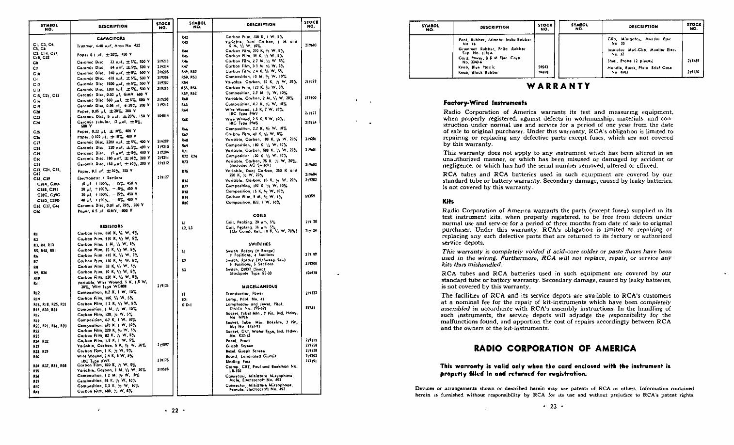
Performance of the WO-33A depends upon the quality of the components employed. If it should be necessary to replace any of the component parts, only RCA replacement parts or equivalents of those shown in the Replacement· Farts List of this instruction booklet should be used.
The chassis may be removed from the case by removing two screws on each side of the case, and three screws from the bottom of the case. The panel ~nd chassis assembly may then be pulled forward and out of the case.
If any alignment adjustments are made, the line voltage should be 117 volts at 50-60 cps. If trouble is encountered, voltage readings should be taken and compared with the operating voltages shown on the schematic diagram. Conventional trouble-shooting techniques should be used to locate trouble. Resistance and continuity checks can then be made to isolate the defective section or stage.
Astigmatism Adjustment
1. Turn on the WO-33A and allow at least 15 minutes warm-up time.
2. Set the H/SWEEP SEL to "LINE", the bandwidth control to "CAL", and adjust the PHASE, V CAL, and H GAIN· control· for a circular pattern approximately one inch in diameter.
3. With a screw -priver, adjust potentiometer R-68 for best possible focus at all points on the circle. R-68 is located on top of the chflssis.
Vertical Attenuator Alignment
Alignment of the frequency-compensated. stepattenuator requires the use of a square-wave or clipped sine-wave signal of about 1000 cps in frequency.
1. Connect the blue clip of the WG-349A probe and cable to the square wave source.
2. Set the V RANGE switch to 60.
3. Adjust the scope controls so that two square waves, about an inch high and two inches wide are displayed on the screen.
4. Adjust C-6 so that the square waves are Hattopped, without overshoot spikes or drooping corners.
5. Reset the V RANGE control to 20, and reset '.r the amplitude of the square wave generator. Adjust
C-5 as in "4" above.
6. Repeat this process for V RANGE positions 6 and 2. The desired trimmer capacitor can be identified on the range switch by touching it with the finger and noting the appearance of a random noise signal on the CRT screen.
7. Now connect the square wave generator to the yellow clip of the WG-349A probe and cable. With the V RANGE control on position 2, adjust capacitor C-l for a Hat top trace without overshoot spikes or drooping corners.
Internal Calibrator Control Adjustment
1. Connect an audio oscillator or square wave generator to the blue clip of the WG-349A probe and cable. Set the V RANGE control to position 2. Adjust the signal source for full scale deHection on the CRT.
2. Transfer the signal source to the yellow clip lead of the WG-349A probe, and rotate the V RANGE control to position .2, and adjust potentiometer R-l1 for full screen deHection.
RCA Repair Service
RCA maintains a complete repair service for the adjustment, calibration, and maintenance of RCA test equipment. If it becomes necessary to service this equipment, the report forms enclosed in this booklet should be filled out as described. It is important that:
1. Test equipment be packed carefully.
2. A full description oLthe trouble be included in the report.
Attention to these details will help prevent damage in transit and delay in repairs.
• 21 •
SYMBOL NO.
CI.C:;.c., C5. CI. C2. CI4, CI1, CII, C12 C. C. C'" Co,
"" C" CIS, C21. Cll
C" C" c. cn C><
c" c" e" c. en c. c" Cll. C)~. Cl5, e., CUI, en
ClIA, Cl9A ClIB, cnB C)8C. C)9C ClID, C)7D
CU, Cll, Ctl C<O
" " Il. 11.4, Ril RS. R4I, R51 .. " .. Rt.R26 ... '" '" ,,. RI5, RI8, RH, Rli RI6, Rll, III
'" '" R20. R21. RiI, RIO on
'" R:M 1112 ,. lUI, R2'I
'" Rl4, 1ll1, 151, RSI ,n
'" ,n ,~ , ..
CA'ACITORS
Pcpor 0.1 "f, ±20'1 •• 400 V
Coram,c D .. c, Z2 ~~f, :t; 5'1.. 500 V
C.,amic Diu:. """I. :t;S'1., 500 V Co,amic Oi,c. 140 ""f, :t;5"/. 500 V Co,amic Oi,c, 410 ""I. ;t:5'1., 500 V Co,amic Disc, 1500 ""f, ;t:5'!.. 500 V C.,amlc Di,c, 1100 ""', ;t: 5'1., 500 V Corami, Oioe, 0.02 "I. GMV, .00 V Cuamic Diu:. SW ""I. ;t: 5'1.. 500 V Co,omic Oioe. 0.05 ~f. ;t:2O,. .. 200 V Popor, 0.05 "f. ;t:2O'1..2OO V C.,om,c Oio<. 5 I'"f, ±20'1., ISO V Coramic Tubulo" 12 ""I. ;t:5,.,.
"" Pop." 0.21 "f, ± 10'1..400 V Pap.r. 0022 "f, ;t:IO'1.. 400 V
C.,amic Di"" 2100 ""I. ± 5'1 •• 400 V Co.amic Diu:. 220 ""I, ;t:S"/..400 V C.ramic Di,c. IS ""f, ±S'1.. 500 V Co,amic D"c, Ito ""I. ;t: 10" .. 200 V Co,amic D"c. 150 ""f, ;t:IO%, 200 v Papo,. 0.1 "I. ;t:20%. 200 V
~Ioclrolyllc: 4 Soclion, 10 "f + 100%, - IS"/.. 450 V
20 "I, + 100,. .. -15%. 450 v 20 "f. + 100'.4. - 15,.., 450 V 40 "I, + 100%, -15'1" 400 V
C.,amlC Di.c, 0.01 "f, 20,. .. 500 V Popo" 0 5 ~I, GMV. 1000 V
RESISTORS
Ca,ban fJlm. 680 K, ';' W, 5'1. Ca,ban f'lm. 910 K, ';' W, 5,.. Ca,bon film. I 101, ';' W, 5'1. Ca,ban film. IS K, ';' w. 5,.. Ca,ban f'lm. 410 K. '/I W. 5'1 • Corban film, 110 K, ';' w. 5,.. Co,b"n film. ]3 K, 'f, W, 5"/. Ca,bon fdm. 10 K, '/> W, 5,.. Ca,bon film. 110 K. '/> W, 5% Va'iebl., Wi,o Wound,S K. 1.5 W,
20,.., Wirt Typ. WCl(JI Campo,il'on, 1,1 K. I w. 10% Carbon (oilm, IOC, 'I! w. 5% Ca,bon Film, 12K, '/I W, 5% Compa,ition, I M. 'I. W. 10'1. Co,ban Film, 120. 'I' w. 5'1. Compo,illon.4.1 K. I w. 10"/. Compo.ilion, 410 K. I w. 10% Ca,ban film, 210 K, \I. w. 5r. Ca,ban film, Bl K. 'f, W. 5,.. Ca,ban film, I.B K. I w. 5% Vo,iablo. Ca,ban. 5 K, 't. w. 20'1. Co,bon film. I K. '/> W, 5'1. WIIO Wo~nd, 2.4 K, 5 W, 5%
IRe Typ. pW5 Cm!>o, film. 120 K, 'f, w. 5'1. Va,iabl •• Co,bon. I M. \II W. 2Or. Compa,ilion. 12M. 'h W, 10% C.mpa,ilion, 61 K. '/> W, 10'1. Compa,ition. 3.3 K. 'h W, 10'1. CQ,bon film. '". '/> W.5'1.
STOCK NO.
21ms 21~114
21~205
21'2(1j 219201 119116
1001014
21~2Oi
219210 219204 219211 21~212
21j121
219121
2 It 125
21~5"
.. , '" ,~
,~
,% ..,
SYMBOL NO.
R4~. R52 R50. ~5l
'" ISS, R540
R5'. R62 ... .. , '" .. , '" ,., , .. , .. '" U2 R24
'" '" '" ,n ". '" ...
" L2, L3
" " "
" '" KID·I
• 22 •
DESCRIPTION
Carbon f,lm. 100 K. I W. 5'/ • VO'iob'o! Dual Corban, I 101
& 101.', W. 10,. '"' Ca,bon film, 210 K, 'I> w. 5'/. Ca,bon film. l~ K, 'J. W, 5'k Co,bon film. 2 1 M. ';' W S,. Co,bon Film, II M, 'I> W. 5' • Ca,ban film, 24 K.'{, W. 5,.. Compo,ilion. 10 M. ';' W. 10,.. Vo"oblo Ca,ban. 5(1 K. 'h W, 20"k Ca,bM film, 120 K. ,/> W, S'J. Campo,ilion. 2.1 101 'I> w. 10% Va,iobl •. Ca,bon. 2 M. 'f, W, 10'1. Compa,ifion. 4.1 K. 'f, W, lOr. Wiro Wound. 1.5 K, 1 W. 10'1.,
IRC Typo PWI W"e Wound. 2 5 K. 5 W, 10'1. •
IRC lypo PW5 Compo,ition. 2.2 K, 'f> w. 10'.4 Ca,ban film. 41 K. 'J. W. 5'1. Vo"oblo. Ca,bon. 100 K, Y. w. 20% Compo,ilion. Ito K, 'I> W, 100;. Variablo. Corbon. 500 K, y, W. 20'. Compo.itio" ,20 K, '/, W. 10,.. Vo,iabl •. Ca,bon, 75 K ';' W, 20,. ••
(jncl ... ~.' AC ~"ilcnJ Varioblo. Dual Ca,b"n. 25(1 K and
250 K, ';' W. 20,.. Vo,ioblo. Ca,bon, 10 K, Yo W. 10':1. Compa,ilion, 100 K, '/1 w. 10% Compo'ition. 15 K, 'I> w, 10'/. Ca,bon film. , 101, ';' w. I'. Campo'illan. B20. I W. 10'1 •
COILS
Coil. Poal:ing, 20 "H. 5% Coil, Poak,ng, l6 "H 5~~
(On Compo R .... 10 K. '/> W. 20%J
SWITCHES
Sw'IC~ Rola'y (V Rang. I , Po,itian', 4 50crion<
S."cn. Rola,y (H/S ..... p Sol.) 6 po,ition" 5 50clio",
h,tcn, DPDT 15,ncl Slaclpolo TIPo 55·))
MISCELLANEOUS
T'on,I",mo,. Powo, Lamp. P'lol, No. 41 Lampholdo, and Jowol, Pilot.
Diolco Na. 155-621 50cl:ol. Tub.~ Min. , Pin, Ind. Hdw,.
No NPl6 Socl:.I, Tub. Min. BOlol,ro, I Pin, ~bl No 9122'1l
Sock .. , CRT. Wafer Typ., Iltd. Hdw" Ho. Kn'll
Panol. fran' G,aph Ser.on .... 1, G,aph 5cro.n loo'd. LQmlnO'od Ci,cuil lindinS Po" Clamp. CRT, Poul and "oltman No.
LB·ISlI Canoocto,. Minial ... M,c,ophano,
Mal., ~1.ct,oGraft No, 451 Conn.do, Miniatu,.Microphon.,
fomal •. '~loct'OGrafl No. 4Sl
STOCK NO.
21~60l
21~59'
219201
219.01
21~1I04
21"02
59)59
21~110
21~129
21~I"
219200
10,",11
21~122
51161
21911~
219258 219121 21~20]
212151
SYMBOL NO.
DESCRIPTION STOCK SYMIOL DESCRIPTION NO. NO.
foci, Rubbe'. Allanl,<; India Rubb., Clip, Min,gate,. M •• n., ~I.c N, " N, " G,amm", Rubbe', Philo /lubbe, In,ulala, M,ni.Cllp, Muelle, ~I.c, ,,' Ne. 1181A Ne. 12
Cord, Power, B & 101 Eloc Ce,p. Sn.lI. Probe (2 pioco.) No. ll-lO~
Knob II •• Ple,lie 59541 Hondlo, 81od, PhilO B,i.! Cc •• !(nob, Siock Rubb., '4818 N, 4.01
WARRANTY
Factory~Wired Instruments Radio Corporation of America warrants its test and measurmg equipment. when properly registered, agamst defects in workmanship, materials, and construction under normal use and serVlce for a period of one year from the date of sale to original purchaser. Under thlS warranty, RCA's obligatIOn is limited to repairmg or replacing any defective parts except fuses, which are not covered by this warranty.
This warranty does not apply to any mstrument which has been altered in an unauthorized manner, or which has been misused or damaged by accident or negligence, or which has had the senal number removed, altered or effaced.
RCA tubes and RCA batteries used in such eqmpment are covered by our standard tube or battery warranty. Secondary damage, caused by leaky batteries, is not covered by this warranty.
Kits Radio Corporation of Amenca warrants the parts (except fuses) suppJted 10 its test instrument kits, when properly registered, to be free from defects under normal use and service fOl" a period of three months from date of sale to original purchaser. Under this warranty, RCA's obltgation is limited to repairing or replacing any such defective parts that are returned to its factory or authorized service depots,
This warranty is completely voided if acid-core solder or paste fluxes have been used in the wiring. Furthermore, RCA will not replace, repair, or service any kits thus mishandled.
RCA tubes and RCA batteries used in such equipment are covered by our standard tube or battery warranty. Secondary damage, caused by leaky batteries, is not covered by this warranty,
The facilities of RCA and its service depot~ are available to RCA's customers at a nominal fee for the repair of kit-instruments which have been completely assembled in accordance with RCA's assembly instructions. In the handling of such instruments, the serviCe depots will adjudge the responsibility for the malfunctions found, and apportion the cost of repairs accordingly between RCA and the owners of the kit-instruments.
RADIO CORPORATION Of AMERICA
This warranty is valid only when the card enclosed with the instrument is properly filled in and returned for reCJistration,
STOCK NO.
219485
219120
DeVICes or arrangements shown or described herein may use patent. of RCA or others. Information contained herein IS furnished without responsibility by RCA lor ,ts use and Without prejudice to RCA's patent rights.
23 •


![[VTUP] T-33A Short Checklist 1974](https://img.pdfslide.net/doc/110x75/543b34bfafaf9f4b578b4633/vtup-t-33a-short-checklist-1974.jpg)