Embed Size (px)
Citation preview

RCAR-IIWPG Seat/Head Restraint EvaluationProtocol (Version 3)
Source: Research Council for Automobile RepairsAvailable: http://www.rcar.org/papers.htm
March 2008
RCAR-IIWPG Seat/Head Restraint Evaluation Protocol
1. Purpose
This document describes a Research Council for Automobile Repairs (RCAR) standard for evaluating and rating the ability of seats and head restraints to prevent neck injury in moderate and low-speed rear-end crashes. The procedures and criteria were developed by the International Insurance Whiplash Prevention Group (IIWPG), which is comprised of various insurance industry supported research groups from around the world. These organizations are AZT, Centro Zaragoza, CESVIMap, Folksam, GDV, IAG, ICBC, IIHS, Thatcham, and Winterthur. In adopting this standard, RCAR recognizes that IIWPG continues research on the issue of whiplash injury prevention and RCAR will consider amending the standard in the future at the recommendation of the IIWPG.
The evaluation procedure is a two-stage process, starting with the measurement and rating of the static geometry of head restraints and followed by a dynamic evaluation in a simulated rear-end crash of those seats that meet certain geometric criteria. The procedures for conducting the geometric measurements are described in a separate document.
2. Overview of Evaluation Procedure
A head restraint prevents neck injury in a rear-end crash by supporting an occupant’s neck and head so they can be accelerated together with the torso as the seat and head restraint are driven forward. To accomplish this, a vehicle’s head restraint needs to be tall enough so that the top of the restraint is above the center of gravity of the tallest expected seat occupant’s head. In addition, the top of the restraint should be close to the back of an occupant’s head so that it can contact and support the head early. The farther the restraint is from the head, the less support it can provide and, consequently, the more the head and torso will tend to move separately, creating potentially injurious forces on the neck.
These basic geometric requirements for seat and head restraint design — height and backset — are measured to produce a geometric rating of good, acceptable, marginal, or poor based solely on the adequacy of the restraint to accommodate large segments of the population. This rating procedure is detailed in the RCAR (2008) publication, A Procedure for Evaluating Motor Vehicle Head Restraints. The additional benefits of active head restraints, if any, will be assessed through dynamic testing.
A head restraint design with a geometric rating of acceptable or good will be tested in a simulated 16 km/h rear impact to determine a dynamic rating of how well the restraint supports the torso, neck, and head. The final overall rating of the seat will be a combination of its geometric and dynamic ratings. A seat design with a geometric rating of marginal or poor automatically will receive an overall rating of poor. It will not be subjected to dynamic testing because its geometry is inadequate to protect anyone taller than an average-size adult male.
The performance criteria for the dynamic test are divided into two groups: seat design parameters (two) and test dummy response parameters (two). The first seat design parameter, time to head restraint contact, requires that the head restraint or seatback contact the seat occupant’s head early in the crash. The main purpose of requiring a head restraint to have only a small distance behind the head is to reduce the time until the head is supported by the restraint. Thus, the time-to-head-restraint-contact parameter assures that initially good or acceptable static geometry is not made irrelevant by poor seat design.
Some seats are designed to absorb some of the crash energy so that occupants experience lower forward accelerations. This aspect of performance, the second seat design parameter, is measured by the forward acceleration of the seat occupant’s torso (T1 acceleration). In some cases, these designs may result in later head contact times.
Seats with features that reduce head restraint contact times or have effective energy-absorbing characteristics have been shown to provide better protection from neck injuries in rear crashes than seats with reasonably similar geometry fitted to the same car models (Farmer et al., 2003). The critical values of the seat design parameters have been set consistent with the performance of these benchmark seats
Research Council for Automobile Repairs March 2008 International Insurance Whiplash Prevention Group Page 1 of 28

RCAR-IIWPG Seat/Head Restraint Evaluation Protocol
Research Council for Automobile Repairs March 2008 International Insurance Whiplash Prevention Group Page 2 of 28
and thus are intended to encourage more automakers to adopt design principles that have been shown to work in the real world.
To assure that earlier head contact or lower T1 acceleration actually results in better support for the head, two dummy response parameters also are measured: neck shear force and neck tension force. The critical values of the neck forces are set according to the distribution of neck forces observed in current seats with good geometry.
To receive a good dynamic rating, a head restraint must pass at least one of the seat design parameters and also have low neck forces. If neck forces are moderate or high, then the dynamic rating is only acceptable or marginal. If neck forces are high and neither seat design parameter is passed, then the dynamic rating falls to poor.
The dynamic test consists of a simulated rear crash on a sled device using a BioRID IIg crash dummy to represent a human occupant. The RCAR-IIWPG procedures will use a sled test with standard crash pulse rather than a full-vehicle test. In theory, full-vehicle test results could include the effect that a vehicle’s rear structure might have on seat performance. However, in real-world rear crashes, vehicles experience impacts with a wide range of vehicle types at a variety of speeds. Thus, the seats in rear-struck vehicles can experience a wide range of crash pulses. These RCAR-IIWPG procedures are designed specifically to assess the performance of seats and head restraints, not rear-end structures, the designs of which are driven by many factors other than neck injury prevention.
3. Measurement and Rating of Static Head Restraint Geometry – The Initial Evaluation
The first step in evaluating the rear crash protection afforded by vehicle seats and head restraints is to measure the static head restraint geometry relative to an average-size adult male. Detailed instructions for conducting the static geometry evaluation are described in A Procedure for Evaluating Motor Vehicle Head Restraints (RCAR, 2008),∗ but note again that the geometric evaluation for this protocol makes no allowance for active head restraints, basing it solely on the static measurements as with all other head restraints. The following passage summarizes the principal concepts of the static geometry assessment.
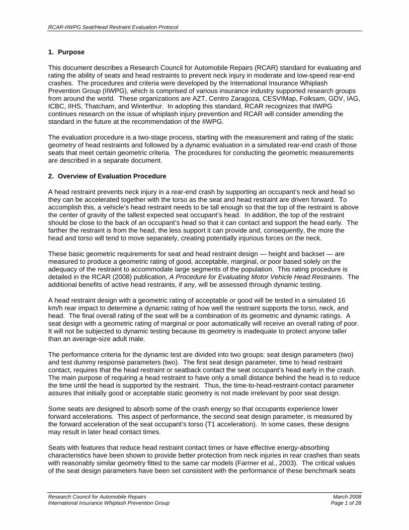
Static geometric evaluations are based on measurements of height and backset that are made with a manikin representing an average-size adult male. To be rated at least marginal, the top of a restraint should be no lower than the center of gravity of the head (no more than 10 cm below the top of the head) and no farther than 11 cm behind the head. Otherwise, the head restraint geometric evaluation is poor. Higher head restraints provide protection for even taller occupants, and closer head restraints can reduce the time the head is unsupported in a rear crash. An acceptable geometric rating implies a head restraint no farther than 8 cm below the top of the head and no farther than 9 cm behind it. Good geometry implies a head restraint no farther than 6 cm below the top of the head and no farther than 7 cm behind it (see Figure 1).
Seats with fixed geometry are rated using the measured height and backset when the seat is adjusted according to the RCAR procedure. Seats with adjustable head restraints that cannot be locked into the adjusted position are rated based on measurements from the unadjusted (lowest and rearmost) position of the head restraint. Seats with locking head restraint adjustments are rated using the midpoint between the lowest/rearmost adjustment and the highest/foremost adjustment.
For head restraints with marginal or poor geometry, the overall rating is poor. Head restraints with good or acceptable geometry undergo dynamic testing, as described below.
∗ NOTE: The seat set-up for the static assessment of head restraint geometry is not the same as the seat set-up for the dynamic
test. Consequently, both this document and A Procedure for Evaluating Motor Vehicle Head Restraints (RCAR, 2008) are required to conduct a complete seat evaluation.
RCAR-IIWPG Seat/Head Restraint Evaluation Protocol
Figure 1 Diagram of Geometric Head Restraint Ratings
Normally, the static evaluation of seat/head restraint geometry should be conducted with the seat and head restraint installed in the vehicle for which they are designed. When this is not possible (e.g., a new or prototype seat design), the static evaluation can be conducted with the seat and head restraint mounted on a crash simulator (sled) or other test fixture. The seat should be attached to the sled or test fixture so that its orientation relative to horizontal is the same as in the vehicle for which it is intended. Also, a representation of the vehicle floor immediately in front of the seat should be attached to the sled or test fixture at the same relative height so that the H-point machine’s feet can be positioned as described in the RCAR procedure. All seat adjustments should be set as described in the RCAR procedure before installing the H-point machine and head restraint measuring device (HRMD). A static evaluation conducted in this way can be used to qualify/disqualify a seat/head restraint design for dynamic testing until the static measurement can be conducted in the vehicle.
4. Dynamic Test Requirements
The dynamic test consists of a rear crash simulation in which a BioRID IIg dummy is positioned in the seat to be tested. The seat is attached to a crash simulation sled and accelerated/decelerated to represent a rear crash with a velocity change (delta V) of 16 km/h. The acceleration profile is roughly triangular, with a peak of 10 g and a total duration of 91 ms. Seats with adjustable head restraints will be tested with the restraints adjusted as in section 5.7.
5. Dynamic Test Procedure
5.1 Acceleration or Deceleration Sled
The dynamic test is intended to simulate a typical rear crash in which the rear-struck vehicle is initially stationary or moving forward very slowly. Consequently, an acceleration sled is recommended for these tests. A deceleration sled, on which the dummy is initially moving rearward at 16 km/h and then stopped, may be used if careful attention is paid to dummy positioning (see step 5.9.5 BioRID positioning requirements). In either case, some sled motion is allowed at the initiation of the test (T = 0). To accommodate different sled types and different relationships between sled motion and the recording of
Research Council for Automobile Repairs March 2008 International Insurance Whiplash Prevention Group Page 3 of 28

RCAR-IIWPG Seat/Head Restraint Evaluation Protocol
Research Council for Automobile Repairs March 2008 International Insurance Whiplash Prevention Group Page 4 of 28
test data, test time will be indexed from the peak sled acceleration as described in section 7 Data Acquisition and Processing.
5.2 Laboratory Environment
The temperature in the test laboratory should be 22.5 ± 3 degrees Celsius (67-78 degrees Fahrenheit) with a relative humidity of 10-70 percent. The BioRID test dummy and seat being tested shall be maintained at this temperature at least 3 hours prior to the test.
5.3 Coordinate System
The coordinate reference frame for measurements is as follows: +X forward (i.e., direction of sled motion), +Y right, +Z down
5.4 Acceleration Pulse
The target sled acceleration and pulse specifications are given in Figure 2 and Table 1, respectively. Sled accelerations should be measured by an appropriate accelerometer attached to the sled platform and recorded according to the Society of Automotive Engineers (SAE, 2003) Standard J211-1. Prior to establishing conformance with the acceleration pulse specification, any quiescent signal bias should be removed∗ from the acceleration measurement. Conformance with pulse duration, peak acceleration and its timing are done with the signal filtered to channel frequency class (CFC) 60. Velocity change (delta V) is judged using velocity calculated from a CFC 180 signal. For delta V calculation, integrate the sled acceleration data from the last time the acceleration passes through zero at the beginning of the trace until the first time the acceleration passes through zero at the end of the trace. Figure 3 shows the typical variation in accelerations from 50 tests conducted on a particular sled.
Figure 2 Target Sled Acceleration and Specification Corridors
∗ This typically is done by subtracting the average value of approximately 100 preimpact data points from each acceleration measurement during the test.

RCAR-IIWPG Seat/Head Restraint Evaluation Protocol
Table 1 Sled Acceleration Pulse Specifications
Acceleration Pulse Characteristic Minimum Maximum
Acceleration at time = 0 ms -0.25 g 0.50 g
Acceleration at time = 27 ms 9.5 g 10.5 g
Time that sled acceleration returns to 0 g 88 ms 94 ms
Velocity change (delta V) 14.8 km/h 16.2 km/h
Figure 3 Typical Variation in Accelerations from 50 Sled Tests
5.5 Attachment of Seat/Head Restraint to Sled
The seat, including all of its adjustment mechanisms and hardware that normally connect it to the vehicle floor (e.g., longitudinal adjustment rails), should be securely fastened to the test sled platform. The attachment should be made so that the seat’s orientation relative to horizontal is the same as it would be in its intended vehicle. The actual height of the seat from the sled platform may be different from its height above the vehicle floor. A simulated floor and toepan, consisting of a horizontal section sufficiently large to rest the dummy’s feet and connected to a section oriented 45 degrees from horizontal and at least 30 cm long, also is attached to the sled platform. Both surfaces should be covered with short-piled carpet. The horizontal floor portion should be mounted at the same height relative to the seat bolts/rails as the heel rest point (section 5.5.1). The fore/aft position of the toepan should be adjustable. Figure 4 shows an example seat both in the vehicle and mounted on the sled platform.
Research Council for Automobile Repairs March 2008 International Insurance Whiplash Prevention Group Page 5 of 28

RCAR-IIWPG Seat/Head Restraint Evaluation Protocol
Figure 4 Attachment of Seat to Test Sled Compared with Vehicle Installation
5.5.1 Determine heel rest point location
The heel rest point is defined in the vehicle (with removable floor mats removed) by using the accelerator pedal as follows.
5.5.1.1 Find the geometric center point of the accelerator pedal contact surface (laterally and vertically). Place a straight edge between the accelerator pedal and the fixed carpeting on the vehicle floor so that the straight edge is tangential to the accelerator pedal surface at the center point. The heel rest point location is then the contact point of the straight edge on the vehicle floor (Figure 5).
Figure 5 Heel Rest Point Location
Research Council for Automobile Repairs March 2008 International Insurance Whiplash Prevention Group Page 6 of 28

RCAR-IIWPG Seat/Head Restraint Evaluation Protocol
5.5.2 Seat belt geometry
A three-point lap/shoulder belt should be used during the test. The belt should be placed across the dummy’s torso, clavicle, and pelvis and be routed above the pelvic angle gauge (if equipped). When testing seats equipped with integrated belts, secure the dummy with the hardware as fitted to the seat.
5.5.3 Trigger active elements
For each seat, it should be ascertained from the manufacturer whether active elements (e.g., active head restraint) are fitted. For each element that requires a trigger, time to fire (TTF) should be specified by the vehicle manufacturer. Supporting data will be requested.
5.6 Set Seat Adjustments
The various seat adjustments possible on many modern vehicle seats should be set according to the following instructions. Because the settings of some adjustments may affect the ranges of other adjustments, the seat should be set according to the order of the procedural steps outlined here. The seatback angle will be set in section 5.9; the initial setting is not important as long as it does not interfere with other adjustments. Seats with automatically adjusting head restraints (i.e., those for which head restraint height adjusts automatically when other seat adjustments are made) should be set according to the instructions in section 5.8.
5.6.1 Initial seat adjustments
All seat adjustments should be set initially as follows. Appendix A provides more detailed descriptions and illustrations of these adjustments.
• Seat track should be in its most rearward position. • Seat height should be set to its lowest position. • Seat tilt should be set to the extreme of its range that puts the cushion angle closest to
zero (horizontal). Section 5.6.2 describes the method for measuring the cushion angle. • Cushion height should be set to its lowest position. • Cushion tilt should be set to the extreme of its range that puts the cushion angle closest
to zero (horizontal). Section 5.6.2 describes the method for measuring the cushion angle. • Lumbar support should be set to its most rearward or least prominent position. • Upper seatback, if separately adjustable from the lower portion, should be rotated fully
rearward. • Cushion extension should be set to its most rearward or least extended position. • Side bolsters should be set to the widest position.
5.6.2 Measure seat cushion angle
Method 1: Locate and mark a point on the forward edge of the top surface of the seat cushion and midway between the right and left edges of the cushion. Locate, mark, and record a second point that is 400 mm rearward along a line parallel to the direction of the sled movement (Figure 6). The cushion angle is the reading from a digital protractor sitting on the surface of the seat with the rearmost end on the rear seat mark.
Method 2: If a coordinate measurement machine (CMM) is used to record the locations of the seat marks, then the sine of the cushion angle is the difference in the Z-coordinates (in mm) of these two points (first minus the second) divided by 400 mm.
Research Council for Automobile Repairs March 2008 International Insurance Whiplash Prevention Group Page 7 of 28

RCAR-IIWPG Seat/Head Restraint Evaluation Protocol
Figure 6 Seat Cushion Angle (400 mm measurement)
5.6.3 Set seat track adjustment to midrange
Method 1: Mark the seat track and the adjacent portion of the seat support structure. Move the seat to its most forward adjustment position and mark the seat track adjacent to the corresponding mark on the seat support structure. Measure the distance between the two seat track marks and mark the track midway between the two marks. Move the seat rearward until the mark on the seat support structure aligns with center seat track (midtrack) mark. The final position will depend on whether the seat track adjusts continuously or incrementally.
Method 2: Mark a hard point on the seat and record its location with a CMM. Move the seat to its most forward adjustment position and record the position of the seat hard point. Move the seat rearward until the marked hard point is midway between the two previously recorded hard point locations. The final position will depend on whether the seat track adjusts continuously or incrementally.
5.6.3.1 Continuously adjusting seat track – The mark on the seat support structure should align (± 2 mm) with the midtrack mark. Alternatively, the hard point should have an X-coordinate that is midway (± 2 mm) between the X-coordinates of the most forward and most rearward adjustment positions.
5.6.3.2 Incrementally adjusting seat track – If the midrange adjustment does not correspond to an indexed adjustment position (± 2 mm), then the seat should be set to the first indexed position rearward of the calculated midpoint.
5.6.4 Set seat height adjustment to midrange
Mark two hard points on the side of the seat that are attached to and move with the cushion frame — one near the front of the cushion and one near the rear. Record the locations of both points with a CMM or measure the vertical heights of the points relative to a fixed reference with a measuring tape. Use the seat height adjustment control(s) to move the seat to its highest position. If front and rear seat heights are adjusted separately (dual control), then make sure that both the front and rear of the seat are raised to their highest positions. Record the locations of the two hard points with the CMM or measure the vertical heights of the points
Research Council for Automobile Repairs March 2008 International Insurance Whiplash Prevention Group Page 8 of 28

RCAR-IIWPG Seat/Head Restraint Evaluation Protocol
relative to a fixed reference with a measuring tape. Then lower the seat until both hard points are midway between their highest and lowest positions. The final position will depend on the type of seat height adjustment control.
5.6.4.1 Single control seat height adjustment – The final position of the seat will depend on whether seat height adjusts continuously or incrementally.
5.6.4.1.1 Continuously adjusting seat height – The rear hard point should be ± 2 mm of the calculated midpoint.
5.6.4.1.2 Incrementally adjusting seat height – If the midrange adjustment does not correspond to an indexed adjustment position (± 2 mm), then the seat height should be set to the first indexed position below the calculated midpoint.
5.6.4.2 Dual control seat height adjustment – If front and rear seat heights are adjusted separately, then lower the front hard point using the front adjustment control and lower the rear hard point using the rear adjustment control. The final position will depend on whether seat height adjusts continuously or incrementally. Note that the front and rear seat height adjustments may need to be iterated to achieve the calculated midpoints.
5.6.4.2.1 Continuously adjusting seat height – Both front and rear hard points should be ± 2 mm of the calculated midpoints. If this is not possible, then the rear hard point should be ± 2 mm of the calculated midpoint and the front hard point as close as possible to the calculated midpoint.
5.6.4.2.2 Incrementally adjusting seat height – If either the front or rear midrange adjustment does not correspond to an indexed adjustment position (± 2 mm), then the seat height should be set to the first indexed position below the calculated midpoint for the corresponding seat hard point.
5.6.5 Set seat cushion height adjustment
The cushion height adjustment uses the points marked on the top surface of the cushion in step 5.6.2.
5.6.5.1 Single control seat cushion height adjustment – Raise the cushion to its highest position and record the location of the rear cushion point (400 mm behind the front edge point). Lower the seat cushion to its midrange position. The final position of the seat will depend on whether seat cushion height adjusts continuously or incrementally.
5.6.5.1.1 Continuously adjusting seat cushion height – The rear cushion point should have a Z-coordinate midway (± 2 mm) between the lowest (initial) and highest positions.
5.6.5.1.2 Incrementally adjusting seat cushion height – If the midrange adjustment does not correspond to an indexed adjustment position (± 2 mm), then the seat cushion height should be set to the first indexed position below the calculated midpoint.
5.6.5.2 Dual control seat cushion height adjustment – Raise the rear of the cushion to its highest position using the rear adjustment control and record the location of the rear cushion point (400 mm behind the front edge point). Lower the rear of the cushion using the rear adjustment control so that the rear cushion point is midway between the lowest (initial) and highest positions. Raise the front of the cushion using the front adjustment control until the cushion angle matches the angle recorded in step 5.6.2. The final position will depend on whether seat cushion height adjusts continuously or incrementally.
Research Council for Automobile Repairs March 2008 International Insurance Whiplash Prevention Group Page 9 of 28

RCAR-IIWPG Seat/Head Restraint Evaluation Protocol
5.6.5.2.1 Continuously adjusting seat cushion height – The rear cushion point Z-coordinate should be ± 2 mm of the calculated midpoint, and the cushion angle should match (± 0.5 degrees) the angle recorded in step 5.6.2.
5.6.5.2.2 Incrementally adjusting seat cushion height – If the rear midrange adjustment does not correspond to an indexed adjustment position, then the rear cushion height should be set to the first indexed position below the calculated midpoint. Likewise, if the cushion angle in step 5.6.2 cannot be matched (± 0.5 degrees) with the front midrange adjustment at an indexed position, then the front cushion height should be set to the next lowest indexed position.
5.6.6 Adjust upper seatback angle
Measure the angle relative to vertical of the head restraint support post or some flat part of the seatback frame. Without changing the adjustment of the lower seatback, move the upper seatback to its most forward position and measure the angle at the same location as the initial measurement. Adjust the upper seatback rearward until the angle is midway (± 0.5 degrees) between the most rearward and most forward angles.
5.6.7 Other seat adjustments
Any seat adjustments not specified in steps 5.6.3 through 5.6.6 should remain in their initial adjustment positions as described in step 5.6.1.
5.7 Head Restraint Test Position
The head restraint should be set in a position closest to that on which the static (RCAR) rating is based. Thus, the test position for the restraint depends on whether it is fixed or adjustable and, if adjustable, whether the adjustments lock. Automatically adjusting head restraints are tested as if they are fixed restraints, and the seat adjustments are set according to section 5.8.
5.7.1 Fixed head restraint
No adjustment of the restraint is possible.
5.7.2 Nonlocking adjustable head restraint
Restraint is adjusted to its lowest vertical adjustment position and/or most rearward horizontal adjustment position.
5.7.3 Locking adjustable head restraint
Restraint is adjusted to the midrange of its vertical and/or horizontal adjustment positions. Only locking adjustments are set to the midrange positions. For example, a restraint with locking height adjustment and nonlocking horizontal adjustment would be set to its midrange vertical position and most rearward horizontal position.
Midrange height position is determined by calculating the geometric mid point between the lowest (locking or nonlocking) and highest locking vertical adjustments, considering only the vertical component of measurement. Similarly, midrange tilt position is determined by calculating the geometric mid point between the most rearward locking and most forward locking horizontal adjustments, considering only the horizontal component of measurement. (Figure 7). The test position will then be selected based on the following conditions:
Research Council for Automobile Repairs March 2008 International Insurance Whiplash Prevention Group Page 10 of 28

RCAR-IIWPG Seat/Head Restraint Evaluation Protocol
• Place the head restraint at the geometric mid point if a locking position exists there (Figure 7A).
• If there is no locking position at the geometric mid point, raise the head restraint by up to 10 mm (Figure 7B). If a locking position exists within this 10mm of travel, that position will be the test position.
• If there is no locking position within 10 mm above the geometric mid point, lower the head restraint to the next lowest locking position (Figure 7C), that position will be the test position.
Once the vertical test position has been determined, the procedure should be repeated for locking horizontal adjustments moving the restraint forward instead of upward and rearward instead of downward.
Figure 7 Examples of Adjustment Positions for Head Restraints with Locking Height
(Locking positions indicated in orange)
Example A Example B Example C (Locking position at (Locking position up to 10 mm (Locking position more than 10 mm geometric mid point) above geometric mid point) above geometric mid point)
5.8 Seating Adjustments: Seats with Automatically Adjusting Head Restraints
The BioRID used in these dynamic tests represents an average-size adult male driver or vehicle occupant. Consequently, seats equipped with head restraints that automatically adjust depending on other seat adjustments (e.g., seat track or height) should be set to a position that most likely would accommodate a seat occupant of the same size. The procedure described in Guidelines for Using the UMTRI ATD Positioning Procedure for ATD and Seat Positioning (Version V) (Insurance Institute for Highway Safety, 2004) should be followed for seat positioning only. The UMTRI ATD positioning procedure must be conducted with the seat installed in a vehicle, then the seat adjustments recorded are transferred to the test seat on the sled. If it is not possible to employ the UMTRI procedure to determine the appropriate seat position for an average-size male seat occupant, then the seat should be set to the middle of its fore/aft adjustment range (see step 5.6.3). Regardless of which method is used to determine the head restraint test position, the seat should be moved rearward from the most forward position to the test position because the starting position can affect the final position of the head restraint.
Research Council for Automobile Repairs March 2008 International Insurance Whiplash Prevention Group Page 11 of 28

RCAR-IIWPG Seat/Head Restraint Evaluation Protocol
5.9 BioRID Positioning
The BioRID test position is based on reference measurements made with the H-point machine and HRMD. Installation of the H-point machine and HRMD follows the procedure described in A Procedure for Evaluating Motor Vehicle Head Restraints (RCAR, 2008) sections 5.2 and 5.3 without changing the seat adjustment obtained in section 5.6.
5.9.1 Install H-point machine and HRMD
Follow the instructions described in sections 5.2 and 5.3 of A Procedure for Evaluating Motor Vehicle Head Restraints (RCAR, 2008). It is important to ensure that the feet of the H-point machine do not contact the angled surface of the simulated toepan during this step. If more than three installations of the H-point machine and HRMD are required to obtain a seatback angle that supports a torso angle of 24-26 degrees, then the seat should be allowed to recover for 15 minutes with nothing in it between each third and fourth installation.
Some indexed seatback adjustments may have more than 2 degrees between adjustments, with none giving a torso angle between 24 and 26 degrees. In such cases, adjust the seatback to the most reclined position that supports a torso angle less than 24 degrees.
5.9.2 Record location of H-point machine’s H-point marker
Use a CMM or other means to record the location of the H-point machine’s H-point marker relative to the seat or sled.
5.9.3 Measure and record reference backset
5.9.3.1 Set the head restraint to the test position described in section 5.7.
5.9.3.2 Locate the screw on the center of the rear surface of the HRMD backset probe.
5.9.3.3 Mark an identifiable point on the head restraint along its vertical centerline.
5.9.3.4 Measure and record the reference backset as shown in Figure 8. This is the horizontal distance between the most rearward point on the HRMD skull (i.e., the screw on the backset probe) and the same identifiable point on the head restraint.
Figure 8 Measuring Backset for BioRID Set-up
Research Council for Automobile Repairs March 2008 International Insurance Whiplash Prevention Group Page 12 of 28

RCAR-IIWPG Seat/Head Restraint Evaluation Protocol
5.9.4 Remove HRMD and H-point machine and install BioRID
5.9.4.1 Allow the seat to recover for 15 minutes with nothing in it before installing the BioRID.
5.9.4.2 Align the BioRID’s midsagittal plane with the centerline of the seat.
5.9.4.3 Adjust the BioRID’s midsagittal plane to be vertical; the instrumentation platform in the head should be laterally level.
5.9.4.4 Adjust the BioRID’s pelvis angle to 26.5 ± 2.5 degrees from horizontal.
5.9.4.5 Position the H-Point 20 ± 10 mm forward of the location recorded in step 5.9.2. Position the H-Point the same vertically ± 10 mm as the location recorded in step 5.9.2, while keeping the pelvis angle at 26.5 ± 2.5 degrees. NOTE: It is recommended that the dummy be positioned as close as possible to the nominal target values; the tolerance window should be used only if there is difficulty achieving the required H-point target or backset value.
5.9.4.6 Adjust the spacing of the BioRID’s legs so that the centerlines of the knees and ankles are 200 ± 10 mm apart.
5.9.4.7 Adjust the BioRID’s feet and/or the adjustable toeboard so that the heels of the dummy’s shoes are resting on the simulated vehicle floor and the tips of the shoes are resting on the toeboard 23-27 cm from the intersection of the heel surface and toe board, as measured along the surface of the toe board (Figure 9). Note if it is not possible to achieve the toe position as specified above, the feet should be positioned with the heels of the dummy’s shoes resting on the simulated vehicle floor and the tips of the shoes resting on the toeboard keeping the following in mind. The foot position should be set so that no joint of the BioRID leg or foot is at its endstop, the heel of the BioRID is not positioned in the intersection of the heel surface and toe board, and the pelvis location found in step 5.9.4.5 is not altered by the position of the leg and foot.
Figure 9 Proper BioRID Feet Positioning
5.9.4.8 Position the BioRID’s arms so that the upper arms contact the seatback and the elbows are bent so that the small fingers of both hands contact the top of the vehicle seat cushion with the palms facing the dummy’s thighs.
Research Council for Automobile Repairs March 2008 International Insurance Whiplash Prevention Group Page 13 of 28

RCAR-IIWPG Seat/Head Restraint Evaluation Protocol
5.9.4.9 Level the instrumentation plane of the head (front/rear and left/right directions) to within ± 1 degree.
5.9.4.10 Measure the BioRID’s backset (distance between the front of the head restraint and the back of the dummy’s head) as follows:
A) Mark the most rearward point on the centerline of the dummy’s skullcap. (NOTE: If using a measuring tape that contours to the shape of the skullcap, then this point is 9.5 cm from the top edge of the skullcap along the midsagittal plane of the skull.)
B) Measure the backset using the same identifiable location on the head restraint that was determined when measuring the HRMD (step 5.9.3.3).
C) The BioRID backset is the horizontal distance between the rearmost point on the dummy’s head and the point on the head restraint marked in step 5.9.3.3 (Figure 10).
Figure 10 Measuring BioRID Backset
5.9.4.11 If the BioRID backset is different from the reference backset (step 5.9.3.4) plus 15 ± 5 mm, then do the following:
A) Tip the head fore/aft no more than ± 1 degree from level to meet the backset requirement. B) If the BioRID backset still cannot be brought closer to the reference backset plus 15 mm,
adjust the pelvis angle and H-point position within their respective tolerance bands, then begin with step 5.9.4.4 and adjust the BioRID position accordingly.
C) If the above iterations still do not allow the backset to come within the specified tolerance for backset target and the H-point position is as far forward as the tolerance allows, then move the H-point forward of the allowed position the smallest distance that allows the backset requirement to be met.
5.9.5 BioRID positioning requirements for tests using decelerating sled
The dummy’s head, T1 vertebra, and the sled should have the same velocity ± 0.1 m/s at T = 0. The back of the dummy’s head and T1 vertebra should be in the same position (± 5 mm) relative to the head restraint at T = 0 as the initial test set-up.
6. BioRID
These tests should be conducted with a BioRID IIg or later revision dummy. The dummy should comply with both spine stature and dynamic response specifications before the test.
Research Council for Automobile Repairs March 2008 International Insurance Whiplash Prevention Group Page 14 of 28

RCAR-IIWPG Seat/Head Restraint Evaluation Protocol
6.1 Spine Curvature Check
With the pelvis adapter plate placed on a level surface with the occipital condyle (OC) angle at 29.5 ± 0.5 degrees, the T2 angle at 37 ± 0.5 degrees, and the neck plate laterally level ± 0.5 degrees, the distance (X) between the H-point and OC pin should be 156 ± 3 mm, and the distance (Z) between the H-point and OC pin should be 609 ± 3 mm (Table 2 and Figure 11).
Table 2 BioRID IIg Spine Curvature Specifications
Measurement Specification
Angle of occipital interface plate relative to horizontal 29.5 ± 0.5 degrees
Angle of T2 vertebra relative to horizontal 37.0 ± 0.5 degrees
Angle of neck plate (lateral) 0 ± 0.5 degrees
H-point indicator to occipital condyle pin (horizontal) 156 ± 3 mm
H-point indicator to occipital condyle pin (vertical) 609 ± 3 mm
Figure 11 BioRID IIg Spine Curvature Check
6.2 Calibration
The dynamic response of BioRID is checked by attaching the spine, torso, and head to a mini sled that is impacted through foam by a 33.4 kg probe at a velocity of 4.76 ± 0.1 m/s. The specified response of the dummy and detailed test specifications are described in Test Procedure: Calibration of BioRID II,
Research Council for Automobile Repairs March 2008 International Insurance Whiplash Prevention Group Page 15 of 28

RCAR-IIWPG Seat/Head Restraint Evaluation Protocol
available from DentonATD, Inc. Generally, if the dummy’s spine curvature changes so that it does not meet the dimensional specifications described in section 6.1, then likely it will no longer meet the dynamic response specifications.
6.3 Clothing
The dummy should be dressed with two pairs of close-fitting, knee-length, spandex (e.g., lycra) pants and two close-fitting, short-sleeved spandex shirts. The under layer of clothes should be worn with the shiny/smooth side of the fabric facing out and the over-clothes with the shiny/smooth side against the underclothes (i.e., dull side facing out). The dummies feet should be shod with size 11 (45 European or 27.9 cm) Oxford-style, hard-soled work shoes (e.g., MIL-S-13192P).
6.4 Instrumentation
The instrumentation required to conduct an RCAR-IIWPG evaluation are listed in Table 3. BioRID IIg includes a loadcell (or structural replacement) at the T1 vertebra; output of this sensor may be recorded at the tester’s discretion. In addition, accelerometers may be used in the head, at the C4 vertebra, T8 vertebra, L1 vertebra, and pelvis.
Table 3 BioRID Instrumentation – Required for RCAR-IIWPG Evaluation
Measurement Location Sensor Type
Back of head Switch to indicate contact with head restraint
Upper neck Loadcell (R.A. Denton model 4985J)
T1 vertebra – left side Acceleration X-direction (e.g., Endevco 7264B-500)
T1 vertebra – right side Acceleration X-direction (e.g., Endevco 7264B-500)
Sled acceleration Acceleration X-direction (e.g., Endevco 7264B-500)
7. Data Acquisition and Processing
The measurement data shall be recorded according to ISO 6487 or SAE J211-1. Table 4 specifies the channel frequency classes for each necessary measurement. Measurement data shall be considered for evaluation until the point in time at which the head rebounds from the head restraint or at 300 ms after T = 0, whichever occurs first.
Table 4 Channel Filter Classes for Evaluation Measurements
Evaluation Measurement Channel Frequency Class (CFC)
Head-to-head restraint contact None
T1 (vertebra) X-acceleration (left and right)
Class 60
Neck X-force (shear) Class 1000
Neck Z-force (tension/compression) Class 1000
Sled acceleration (X) Class 60
Sled acceleration (X) delta V Class 180
Research Council for Automobile Repairs March 2008 International Insurance Whiplash Prevention Group Page 16 of 28

RCAR-IIWPG Seat/Head Restraint Evaluation Protocol
7.1.1 RCAR-IIWPG test time indexing
To normalize the time index among sled laboratory protocols with different T = 0 trigger levels, the time of the occurrence of the maximum acceleration is used as the reference for indexing time. The procedure is described as follows:
7.1.1.1 Record the X-acceleration of the sled in accordance with SAE J211-1.
7.1.1.2 If necessary, remove any data channel DC bias. Typically, the value of the average measurement over 100 samples of the quiescent data channel signal is subtracted from every test measurement.
7.1.1.3 Filter the sled acceleration to CFC 60 as defined by SAE J211-1.
7.1.1.4 Find the measurement that corresponds to the maximum sled acceleration and note the time it occurs.
7.1.1.5 Subtract 27 ms from the time noted in step 7.1.1.4 and use the resulting difference to re-index the time for all test measurements. If the difference is positive (>0), then measurements recorded at the original T = 0 will now occur before T = 0. If the difference is negative (<0), then measurements recorded at the original T = 0 will now occur after T = 0. The peak sled acceleration (filtered data) should occur at exactly 27 ms.
7.1.2 RCAR-IIWPG variable head contact adjustment
Sled accelerations meeting the specified corridors may have different timing that can lead to differences in head contact times recorded on identical seats tested at different labs. To eliminate variation in head restraint contact times between labs, the recorded head contact time must be adjusted to reflect the contact time that would be expected if the exact target pulse was achieved. The procedure for adjusting recorded head contact time is described as follows:
Note: All data referred to in this section must already be time indexed as described in section 7.1.1. See Appendix B for an example of how to adjust the head contact time.
7.1.2.1 Using the sled filtered acceleration (CFC 180), integrate the data from the last time the acceleration passes through zero at the beginning of the trace until the first time the acceleration passes through zero at the end of the trace. Convert to m/s by multiplying by 9.81.
7.1.2.2 Find the time in milliseconds at which the recorded sled velocity change reaches 4 m/s and round the value to the next highest number. For example 61.3 ms should round to 62 ms and 61.8 ms should round to 62 ms. An exact value recorded (i.e. 60.0 ms) will not be rounded.
7.1.2.3 Subtract the time recorded in step 7.1.2.2 from 70 ms. Add the difference to the time indexed head contact time from step 7.1.1.5. The resulting value will be the official head contact time used for evaluation.
7.1.3 RCAR-IIWPG calculations and rounding
Round neck forces and head restraint contact time to the nearest whole Newton and millisecond, respectively, and T1 acceleration to the nearest tenth g. Calculations are listed in section 8.3.
Research Council for Automobile Repairs March 2008 International Insurance Whiplash Prevention Group Page 17 of 28
RCAR-IIWPG Seat/Head Restraint Evaluation Protocol
8. Evaluation Procedure
8.1 Seat Design Parameters
There are two seat design parameters: time to head restraint contact and maximum T1 acceleration.
8.1.1 Time to head restraint contact
Time to head restraint contact must be less than 70 ms to pass this requirement. This limit reflects head restraint contact times achieved by seats with active head restraint designs and acceptable or better static geometry. Time to head restraint contact is the time after the beginning of the sled test (T = 0) that the dummy’s head contacts the head restraint and maintains that contact for at least 40 ms. Contact is indicated by an electrical contact switch attached to either the dummy’s head or the head restraint.
Note: Minor breaks in time to head restraint contact (up to 1 ms) are permissible if it can be proven that these are due to poor electrical contacts, however these must be investigated with reference to the film to ascertain whether the breaks in contact are not due to biomechanical phenomena such as ATD ramping, head restraint or seatback collapse, or “bounce” of the head during non-structural contact with the head restraint.
8.1.2 T1 acceleration
The maximum T1 forward acceleration must be less than 9.5 g to pass this requirement. This limit is based on the maximum T1 accelerations recorded in tests of Volvo Whiplash Injury Prevention System (WHIPS) seats, which include energy-absorbing/force-limiting seatback hinges. Maximum T1 forward acceleration is the average of the highest acceleration recorded by an SAE J211-1-compliant (CFC 60 Hz) and horizontally oriented accelerometer attached to BioRID’s T1 vertebral unit on both left and right sides anytime between the beginning of the test and the time the dummy’s head first leaves contact with the head restraint at the beginning of the rebound phase of the simulated crash.
8.2 Test Dummy Response Parameters
Neck shear and tension forces are measured at the connection between the dummy’s cervical spine and head using an SAE J211-1-compliant (CFC 1000) load cell. The measured neck forces will be classified as low, moderate, or high depending on which region of Figure 12 the data point representing the maximum neck tension and maximum rearward neck shear force lies. These regions are bounded by curves representing the 30th and 75th percentiles of the joint probability distribution of neck shear and neck tension forces among tested seats with good geometry. Thus, low neck forces mean that measured forces are as low or lower than 30 percent of seats with good geometry, when shear and tension are considered jointly; high neck forces mean that measured forces are higher than 75 percent of seats with good geometry. Although these criteria are based on 2004 model year seats, they will be maintained for the foreseeable future. The goal was to establish force limits that were achievable with current design knowledge.
Research Council for Automobile Repairs March 2008 International Insurance Whiplash Prevention Group Page 18 of 28

RCAR-IIWPG Seat/Head Restraint Evaluation Protocol
Figure 12 Rating for the Joint Distribution, Maximum Neck Tension and Maximum Neck Shear
0
50
100
150
200
250
300
0 200 400 600 800 1000 1200 1400Maximum upper neck tension (N)
Max
imum
(rea
rwar
d) u
pper
nec
k sh
ear (
N)
LOW Neck Force30th percentile neck forces
from tests of seatswith good geometry
MODERATE Neck Force
HIGH Neck Forceexceeds 75th percentile
of results for seatswith good geometry
8.3 Procedure for Evaluating Neck Shear and Tension
The critical values for neck shear and tension were based on 102 seats with good static geometry ratings. In dynamic tests of these seats, peak neck shear (FX) ranged from 0 to 315 N and peak neck tension (FZ) ranged from 234 to 1365 N. For each test, neck tension values were standardized by subtracting 234 (the minimum) and dividing by 1131 (the range). Neck shear values were similarly standardized by dividing by 315. Thus, the standardized values for both neck shear and tension were between 0 and 1.
Vector sums of the standardized shear and tension values were calculated. Note that the vector sum has no intended biomechanical interpretation. Rather it has a statistical interpretation, indicating how extreme the forces were for a particular seat when shear and tension were considered jointly. In this joint statistical distribution, deviations in the standardized scores for tension and shear are weighted equally in the absence of clear, scientific evidence that one is more important than the other for neck whiplash injury.
Low neck forces are defined as those with vector sums less than or equal to the 30th percentile vector sum for seats with good geometry (≤0.45); high neck forces were defined as those with vector sums exceeding the 75th percentile sum for seats with good geometry (>0.825). The remaining vectors were termed moderate forces.
These vector sums form quarter-circle boundaries on the bivariate distribution of standardized shear and tension forces, which can be written as follows:
{FX / 315}2 + {(FZ – 234) / 1131}2 < {0.450}2 for low forces
and
{FX / 315}2 + {(FZ – 234) / 1131}2 > {0.825}2 for high forces.
Research Council for Automobile Repairs March 2008 International Insurance Whiplash Prevention Group Page 19 of 28

RCAR-IIWPG Seat/Head Restraint Evaluation Protocol
Alternatively, the boundaries can also be defined on the unstandardized bivariate distribution of neck shear and tension forces (see Figure 12), as follows:
FX = 142 for FZ ≤ 234 = 142 SQRT{1 – (FZ – 234)2 / (509)2} for 234 < FZ < 743 = 0 for FZ ≥ 743
and
FX = 260 for FZ ≤ 234 = 260 SQRT{1 – (FZ – 234)2 / (933)2} for 234 < FZ < 1167 = 0 for FZ ≥ 1167.
For computational ease, intercept values of these curves were rounded up, yielding:
FX = 150 for FZ ≤ 234 = 150 SQRT{1 – (FZ – 234)2 / (516)2} for 234 < FZ < 750 = 0 for FZ ≥ 750
and
FX = 260 for FZ ≤ 234 = 260 SQRT{1 – (FZ – 234)2 / (936)2} for 234 < FZ < 1170 = 0 for FZ ≥ 1170.
8.4 Dynamic Rating
The dynamic rating for dynamically tested seats will be good, acceptable or marginal for those seats registering low, moderate, or high neck forces, respectively, and also meeting one of the two seat design parameter requirements: T1 X-acceleration ≤9.5 g or time to head restraint contact ≤70 ms. Seats failing to meet one of the seat design parameters will be rated good, acceptable, or marginal depending on whether the neck forces were classified as low, moderate, or high. Similarly, seats failing to meet both seat design requirements will be rated acceptable, marginal, or poor. Table 5 summarizes the requirements for dynamic ratings at each level.
Table 5 Dynamic Rating Requirements
Seat Design Criteria Neck Force Classification Dynamic Rating
T1 X-acceleration ≤9.5 g OR Time to head restraint contact ≤70 ms
Low Good
Moderate Acceptable
High Marginal
T1 X-acceleration >9.5 g AND Time to head restraint contact >70 ms
Low Acceptable
Moderate Marginal
High Poor
8.5 Overall Rating
The static geometry rating and the dynamic rating are combined as shown in Table 6 to establish the overall rating for the seat. A seat with a static rating of Acceptable due to backset and not height will earn a Good overall rating if the dynamic rating is Good. This exception was made to give credit to seats with geometry that is tall enough to support an averaged size male and when dynamically tested, can compensate for a larger backset.
Research Council for Automobile Repairs March 2008 International Insurance Whiplash Prevention Group Page 20 of 28

RCAR-IIWPG Seat/Head Restraint Evaluation Protocol
Table 6 Formulation of Overall Rating
Geometric Rating Dynamic Rating Overall Rating
Good Good Good
Acceptable Acceptable
Marginal Marginal
Poor Poor
Good Height Good
Acceptable Good Acceptable
Acceptable Acceptable
Marginal Marginal
Poor Poor
Marginal No dynamic test Poor
Poor No dynamic test Poor
9. References
Farmer, C.M.; Wells, J.K.; and Lund, A.K. 2003. Effects of head restraint and seat redesign on neck injury risk in rear-end crashes. Traffic Injury Prevention 4:83-90.
Insurance Institute for Highway Safety. 2004. Guidelines for using the UMTRI ATD positioning procedure for ATD and seat positioning (version V). Arlington, VA.
Research Council for Automotive Repairs. 2008. A procedure for evaluating motor vehicle head restraints. Issue 3, March 2008. Wiltshire, United Kingdom.
Society of Automotive Engineers. 2000. 2000 SAE Handbook, Vol. 3 – On-Highway Vehicle and Off-Highway Machinery. Warrendale, PA.Society of Automotive Engineers. 2003. Instrumentation for impact test; Part 1: Electronic instrumentation. SAE Standard J211-1. Warrendale, PA.
10. Additional References
Chapline, J.F.; Ferguson, S.A.; Lillis, R.P.; Lund, A.K.; and Williams, A.F. 2000. Neck pain and head restraint position relative to the driver’s head in rear-end collisions. Accident Analysis and Prevention Special Issue: Whiplash 32:287-97.
Davidson, J. 2000. Development of a mechanical model for rear impacts: evaluation of volunteer responses and validation of the model (doctoral thesis). Gutenberg, Sweden: Chalmers University of Technology.
Farmer, C.M.; Wells, J.K.; and Werner, J.V. 1999. Relationship of head restraint positioning to driver neck injury in rear-end crashes. Accident Analysis and Prevention 31:719-28.
Insurance Institute for Highway Safety. 2003. Most adjustable head restraints aren’t being adjusted upward. Status Report 38(9):3. Arlington, VA. Available: http://www.highwaysafety.org/srpdfs/sr3809.pdf.
Motor Insurance Repair Research Centre – Thatcham. 2003. Save your neck, Autumn 2003. Berkshire, United Kingdom.
Research Council for Automobile Repairs March 2008 International Insurance Whiplash Prevention Group Page 21 of 28

RCAR-IIWPG Seat/Head Restraint Evaluation Protocol
Research Council for Automobile Repairs March 2008 International Insurance Whiplash Prevention Group Page 22 of 28
Olsson, I.; Bunketorp, O.; Carlsson, G.; Gustafsson, C.; Planath, I.; Norin, H.; and Ysander, L. 1990. An in-depth study of neck injuries in rear-end collisions. Proceedings of the 1990 International IRCOBI Conference on the Biomechanics of Impacts, 269-80. Bron, France: International Research Council on the Biomechanics of Impacts.
Viano, D.C. and Gargan, M.F. 1995. Headrest position during normal driving: implications to neck injury risks in rear crashes. Proceedings of the 39th Annual Conference of the Association for the Advancement of Automotive Medicine, 215-29. Des Plaines, IL: Association for the Advancement of Automotive Medicine.
Revision History
Section 2 (edited) – Removed language describing steps of previous RCAR protocol “A Procedure for Evaluating Motor Vehicle Head Restraints: Issue 2.”
Section 5.7.3 (edited) – Changed procedure for determining the test position for adjustable locking head restraints.
References – Updated reference to RCAR “A Procedure for Evaluating Motor Vehicle Head Restraints.”

RCAR – IIWPG Seat/Head Restraint Evaluation Protocol
Appendix A – Seat Adjustment Definitions
Definition Image Additional Images
Seat Track – An adjustment that moves the entire seat (seat cushion and seatback) in the fore and aft directions.
Seatback – An adjustment that rotates the entire seatback, independently of the seat cushion, about a pivot at the seatback/seat cushion joint, therefore, changing the angle of the seatback relative to the seat cushion.
Seat Height – An adjustment that moves the entire seat vertically (seat cushion and seatback in unison). This adjustment must keep the angle of the seat cushion the nearly the same relative to the ground. This can be one control (two-way) that moves the whole seat in unison or a combination of controls (four-way – a toggle or multiple knobs) that, when used together, keep the angle of the seat cushion nearly the same relative to the ground.
Two-way
(one control)
+ =
Four-way (toggle or multiple knobs) NOTE: It is not possible to have four-way
seat height AND seat tilt
Seat Tilt – An adjustment that rotates the entire seat (seat cushion and seatback in unison). This adjustment rotates a seat in such a way to significantly change the angle of the seat cushion, relative to ground, from its full-down position. This adjustment can move either the front or rear of the seat in order to change the angle.
OR
Research Council for Automobile Repairs March 2008 International Insurance Whiplash Prevention Group Page 23 of 28

RCAR – IIWPG Seat/Head Restraint Evaluation Protocol
Research Council for Automobile Repairs March 2008 International Insurance Whiplash Prevention Group Page 24 of 28
Definition Image Additional Images
Seat Cushion Height – An adjustment that moves the seat cushion vertically, independent of the seatback, while keeping angle of the seat cushion nearly the same relative to the ground. This can be one control (two-way) that moves the whole seat cushion in unison or a combination of controls (four-way – a toggle or multiple knobs) that, when used together, keep the angle of the seat cushion nearly the same relative to the ground.
Two-way
(one control)
+ =
Four-way (toggle or multiple knobs) NOTE: It is not possible to have four-way seat cushion height AND seat cushion tilt
Seat Cushion Tilt – An adjustment that moves the seat cushion, independent of the seatback, in such a way to significantly change the angle of the seat cushion, relative to ground, from its full-down position. This adjustment can move either the front or rear of the seat cushion in order to change the angle.
OR
Lumbar Support – An adjustment that causes the lower center portion of the seatback to protrude in order to provide support to the lumbar section of an occupant’s spine.
Upper Seatback – An adjustment that rotates only the upper portion of the seatback about a pivot point in the seatback. This adjustment will change the angle of the upper seatback relative to the lower portion of the seatback.

Research Council for Automobile Repairs March 2008
RCAR – IIWPG Seat/Head Restraint Evaluation Protocol
International Insurance Whiplash Prevention Group Page 25 of 28
Definition Image Additional Images
Cushion Extension – An adjustment that moves or extends a portion of the seat cushion forward so that the overall length of the cushion can be increased.
Side Bolsters – An adjustment the moves the sides of the seatback or seat cushion so that the contour of the seat can be changed.
Head Restraint Height – An adjustment that moves the head restraint vertically.
Head Restraint Tilt – An adjustment that moves the head restraint horizontally.
OR OR

RCAR – IIWPG Seat/Head Restraint Evaluation Protocol
Appendix B – Example Head Contact Adjustment
Step 1. Record sled acceleration.
-4
-2
0
2
4
6
8
10
12
-0.05 0 0.05 0.1 0.15 0.2 0.25 0.3 0.35
Step 2. Remove signal bias.
Step 3. Filter sled acceleration to CFC 60 to determine time shift and time shift all data (including head contact time).
-4
-2
0
2
4
6
8
10
12
-0.05 0 0.05 0.1 0.15 0.2 0.25 0.3 0.35
Peak acceleration10.0 g at 27 ms
Research Council for Automobile Repairs March 2008 International Insurance Whiplash Prevention Group Page 26 of 28

RCAR – IIWPG Seat/Head Restraint Evaluation Protocol
Step 4. Filter sled acceleration data to CFC 180. Integrate from the last time the acceleration passes through zero at the beginning of the trace until the first time the acceleration passes through zero at the end of the trace.
-4
-2
0
2
4
6
8
10
12
-0.05 0 0.05 0.1 0.15 0.2 0.25 0.3 0.35
Integrate data betweenvertical lines only
Step 5. Convert from g to m/s by multiplying by 9.81.
Step 6. Find the time at which the velocity change reaches 4 m/s and round the value to the next highest number. For example, 61.3 ms should round to 62 ms and 61.8 ms should round to 62 ms. An exact value recorded (e.g., 60.0 ms) will not be rounded.
-1
0
1
2
3
4
5
-0.008 0.012 0.032 0.052 0.072
4 m/s
67.6 ms
Research Council for Automobile Repairs March 2008 International Insurance Whiplash Prevention Group Page 27 of 28

RCAR – IIWPG Seat/Head Restraint Evaluation Protocol
Step 7. Subtract the time recorded in step 6 from 70 ms. Add the difference to the time indexed head contact time from step 3. The resulting value will be the official head contact time (HCT) used for evaluation.
-2.5
-2.0
-1.5
-1.0
-0.5
0.0
0.5
1.0
-0.05 0 0.05 0.1 0.15 0.2 0.25 0.3 0.35
60 ms + 2 msHCT = 62 ms
Research Council for Automobile Repairs March 2008 International Insurance Whiplash Prevention Group Page 28 of 28