Embed Size (px)
Citation preview
��������������� �� ����
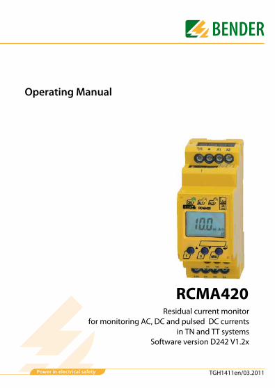
Operating Manual
RCMA420Residual current monitor
for monitoring AC, DC and pulsed DC currentsin TN and TT systems
Software version D242 V1.2x
TGH1411en/03.2011

Dipl.-Ing. W. Bender GmbH & Co. KGLondorfer Str. 65 • 35305 Grünberg • GermanyPostfach 1161 • 35301 Grünberg • Germany
Tel.: +49 6401 807-0Fax: +49 6401 807-259
E-Mail: [email protected]: http://www.bender-de.com
© Dipl.-Ing. W. Bender GmbH & Co. KG
All rights reserved.Reprinting only with permissionof the publisher.Subject to change!

Table of Contents
1. Effective use of this manual ........................................................................... 5
1.1 Notes for the user ............................................................................................. 51.2 Intended use ...................................................................................................... 51.3 Information about factory setting ............................................................. 6
2. Safety information ........................................................................................... 7
2.1 Safety information ........................................................................................... 72.2 Work activities on electrical installations ................................................ 7
3. Function ............................................................................................................. 9
3.1 Device features ................................................................................................. 93.2 Function ............................................................................................................... 93.2.1 Connection monitoring .............................................................................. 103.2.2 Fast response value query ......................................................................... 103.2.3 Automatic self test ........................................................................................ 103.2.4 Manual self test .............................................................................................. 103.2.5 Functional faults ............................................................................................ 103.2.6 Set the number of reload cycles .............................................................. 113.2.7 Assigning alarm categories to alarm relays K1/K2 ............................ 113.2.8 Time delays t, ton and toff ....................................................................... 113.2.9 Starting delay t ............................................................................................... 113.2.10 Response delay ton1/2 ................................................................................ 113.2.11 Delay on release toff .................................................................................... 113.2.12 Residual current monitoring in window discriminator mode ...... 123.2.13 Password protection (on, OFF) ................................................................. 123.2.14 Factory setting FAC ...................................................................................... 123.2.15 Erasable history memory ............................................................................ 123.2.16 External, combined test/reset button T/R ............................................ 123.2.17 Fault memory ................................................................................................. 12
3TGH1411en/03.2011

Table of Contents
4. Installation and connection ......................................................................... 13
5. Operation and setting .................................................................................. 15
5.1 Display elements in use .............................................................................. 155.2 Function of the operating elements ...................................................... 165.3 Menu structure ............................................................................................... 175.4 Display in standard mode .......................................................................... 185.5 Display in menu mode ................................................................................ 195.5.1 Parameter query and setting: overview ................................................ 195.5.2 Changeover from overcurrent to undercurrent mode
or to window mode ...................................................................................... 215.5.3 Response value setting for overcurrent: ............................................... 225.5.4 Setting the fault memory and alarm relay operating mode .......... 235.5.5 Assigning alarm categories to the alarm relays ................................. 245.5.6 Set the time delays ....................................................................................... 265.5.7 Changing from overcurrent operation to window operation ...... 275.5.8 Factory setting and password protection ............................................ 275.5.9 Restoring factory settings .......................................................................... 295.5.10 Device information query (Example) ..................................................... 295.5.11 History memory query ................................................................................. 295.6 Commissioning .............................................................................................. 305.7 Factory setting ................................................................................................ 30
6. Technical data ................................................................................................ 31
6.1 Data in tabular form ..................................................................................... 316.2 Standards, approvals and certifications ................................................ 346.3 Ordering information ................................................................................... 356.4 Error codes ....................................................................................................... 36
INDEX .................................................................................................................... 37
4 TGH1411en/03.2011

1. Effective use of this manual
1.1 Notes for the user
This manual is intended for experts in electrical engineering and elec-tronics!
In order to make it easier for you to find specific text passages or references in this manual and for reasons of comprehensibility, important information is emphasized by symbols. The meaning of these symbols is explained below:
1.2 Intended useThe AC/DC sensitive residual current monitor RCMA420 is designed for use in earthed systems (TN and TT systems) where DC and AC fault currents may oc-cur. These are in particular loads containing six-pulse rectifiers or one way rec-tifiers with smoothing, such as converters, battery chargers, construction site equipment with frequency-controlled drives.Two separately adjustable response ranges allow to distinguish between pre-warning (IΔn1 = 50…100 % of the set response value IΔn2) and alarm ( IΔn2). Since the values are measured with measuring current transformers, the RCMA is nearly independent of the nominal voltage and the load current of the system being monitored.
Information calling attention to hazards are markedwith this warning symbol.
Information intended to assist the user to make optimumuse of the product are marked with the Info symbol.
5TGH1411en/03.2011

Effective use of this manual
1.3 Information about factory settingPage 30 provides a summary of all factory settings.If you want to reset the residual current monitor to factory settings, refer to page 29.
6 TGH1411en/03.2011

2. Safety information
2.1 Safety informationIn addition to this data sheet, the documentation of the device includes a sheet entitled "Important safety instructions for BENDER products“.
2.2 Work activities on electrical installations All work activities necessary for installation, commissioning or work
activities during operation of electrical devices or systems are to be car-ried out by adequately skilled personnel.
Observe the relevant regulations applying to work on electrical instal-lations, in particular DIN EN 50110 or its subsequent regulations.
If the equipment is used outside the Federal Republic of Germany, the respective national standards and regulations are to be observed. The European standard EN 50110 is recommended to be used as a direc-tive.
Unprofessional work activities on electrical installationsmay result in a threat of danger to life and limb!
7TGH1411en/03.2011

Safety information
8 TGH1411en/03.2011

3. Function
3.1 Device features AC/DC sensitive residual current monitor Type B according to IEC
62020 and IEC 60755 Two separately adjustable response ranges (prewarning, alarm) Adjustable switching hysteresis r.m.s. value measurement Starting delay, response delay and delay on release Measured value display via multi-functional LC display Alarm indication via LEDs (AL1, AL2) and changeover contacts (K1, K2) N/C operation or N/O operation selectable Password protection against unauthorized parameter changing Fault memory function can be switched off CT connection monitoring
3.2 FunctionOnce the supply voltage Us is applied, the starting delay is activated. Meas-ured values changing during this time do not influence the switching state of the alarm relays. Residual current measurement takes place via an external measuring current transformer of the W20AB…W60AB series. The currently measured value is shown on the LC display. In this way any changes, for exam-ple when circuits are connected to the system, can be recognized easily. If the measured value exceeds one or both response values, the response delays ton1/2 start running. Once the response delay ton1/2 has elapsed, the K1/K2 alarm relays switch and the alarm LEDs AL1/AL2 light up. If the residual cur-rent falls below the release value (response value minus hysteresis), the delay on release toff begins. Once the release delay toff has elapsed, the alarm relays return to their original state and the alarm LEDs AL1/AL2 go out. If the fault memory is activated, the alarm relays remain in the alarm state and the LEDs light until the reset button is pressed or until the supply voltage is interrupted.
9TGH1411en/03.2011
Function
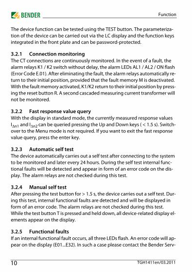
The device function can be tested using the TEST button. The parameteriza-tion of the device can be carried out via the LC display and the function keys integrated in the front plate and can be password-protected.
3.2.1 Connection monitoringThe CT connections are continuously monitored. In the event of a fault, the alarm relays K1 / K2 switch without delay, the alarm LEDs AL1 / AL2 / ON flash (Error Code E.01). After eliminating the fault, the alarm relays automatically re-turn to their initial position, provided that the fault memory M is deactivated. With the fault memory activated, K1/K2 return to their initial position by press-ing the reset button R. A second cascaded measuring current transformer will not be monitored.
3.2.2 Fast response value queryWith the display in standard mode, the currently measured response values IΔn1 and IΔn2 can be queried pressing the Up and Down keys ( < 1.5 s). Switch-over to the Menu mode is not required. If you want to exit the fast response value query, press the enter key.
3.2.3 Automatic self testThe device automatically carries out a self test after connecting to the system to be monitored and later every 24 hours. During the self test internal func-tional faults will be detected and appear in form of an error code on the dis-play. The alarm relays are not checked during this test.
3.2.4 Manual self testAfter pressing the test button for > 1.5 s, the device carries out a self test. Dur-ing this test, internal functional faults are detected and will be displayed in form of an error code. The alarm relays are not checked during this test.While the test button T is pressed and held down, all device-related display el-ements appear on the display.
3.2.5 Functional faultsIf an internal functional fault occurs, all three LEDs flash. An error code will ap-pear on the display (E01...E32). In such a case please contact the Bender Serv-
10 TGH1411en/03.2011

Function
ice.
3.2.6 Set the number of reload cyclesIf faults occur only temporarily, but recurrently, in the system being moni-tored, with the fault memory M deactivated, the alarm relays would switch synchronously to the error status.RL in the out menu can be used to limit the number of these changeover proc-esses. As soon as the preset number of switching cycles is exceeded, the fault memory will come on and an activated alarm remains stored.
3.2.7 Assigning alarm categories to alarm relays K1/K2The alarm categories device error, residual current IΔn1, residual current IΔn2 or alarm by device test can be assigned to the alarm relays via the "out" menu.
3.2.8 Time delays t, ton and toffThe times t, ton and toff, described below, delay the output of alarms via LEDs and relays.
3.2.9 Starting delay tAfter connection to the supply voltage, the alarm indication is delayed by the preset time t (0...10 s).
3.2.10 Response delay ton1/2If the residual current increases above or falls below the response value the re-sponse time tan expires. After the expiry of the response time an alarm is sig-nalled. A set response delay ton1/2 (0...10 s) adds up to the device-related operating time tae and delays alarm signalling (total delay time tan = tae + ton).If the residual current fault changes from a value above the response value to a value below the response value, an alarm will not be signalled.
3.2.11 Delay on release toffWhen no alarm exists after deactivating the fault memory, the alarm LEDs go out and the alarm relays switch back to their initial position. After activating the delay on release (0...99 s), the alarm state is continuously maintained for the selected period.
11TGH1411en/03.2011
Function
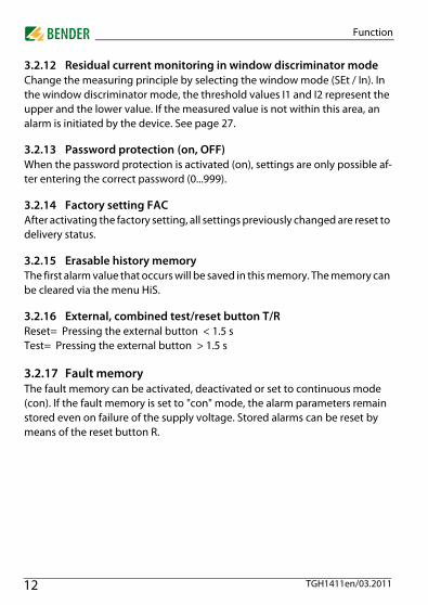
3.2.12 Residual current monitoring in window discriminator modeChange the measuring principle by selecting the window mode (SEt / In). In the window discriminator mode, the threshold values I1 and I2 represent the upper and the lower value. If the measured value is not within this area, an alarm is initiated by the device. See page 27.
3.2.13 Password protection (on, OFF)When the password protection is activated (on), settings are only possible af-ter entering the correct password (0...999).
3.2.14 Factory setting FACAfter activating the factory setting, all settings previously changed are reset to delivery status.
3.2.15 Erasable history memoryThe first alarm value that occurs will be saved in this memory. The memory can be cleared via the menu HiS.
3.2.16 External, combined test/reset button T/RReset= Pressing the external button < 1.5 sTest= Pressing the external button > 1.5 s
3.2.17 Fault memoryThe fault memory can be activated, deactivated or set to continuous mode (con). If the fault memory is set to "con" mode, the alarm parameters remain stored even on failure of the supply voltage. Stored alarms can be reset by means of the reset button R.
12 TGH1411en/03.2011

4. Installation and connection
Dimension diagram, drawing for screw mounting, push-wire ter-minal connection
The front plate cover is easy to open at the lower part marked by an arrow.
Ensure safe isolation from supply in the installation area. Ob-serve the installation rules for live working.
�
�
�
����
�
���
�
�����
�����
��
������
������
�����������������
13TGH1411en/03.2011
Installation and connection
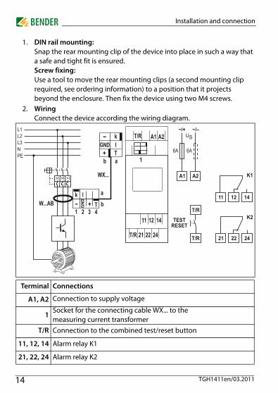
1. DIN rail mounting:Snap the rear mounting clip of the device into place in such a way that a safe and tight fit is ensured.Screw fixing:Use a tool to move the rear mounting clips (a second mounting clip required, see ordering information) to a position that it projects beyond the enclosure. Then fix the device using two M4 screws.
2. WiringConnect the device according the wiring diagram.
Terminal Connections
A1, A2 Connection to supply voltage
1Socket for the connecting cable WX... to the measuring current transformer
T/R Connection to the combined test/reset button
11, 12, 14 Alarm relay K1
21, 22, 24 Alarm relay K2
���
�� ����
�� ����
����
���
���
� � � �
���
�
����
�
�����
�
�
�
��
�
�
���
14 TGH1411en/03.2011
5. Operation and setting
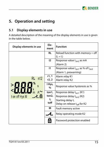
5.1 Display elements in useA detailed description of the meaning of the display elements in use is given in the table below.
Display elements in useEle-
mentFunction
RL Reload function with memory = off (L = I.)
I2 Response value IΔn2 as mA (Alarm 2)
I1 Response value IΔn1 as % of IΔn2(Alarm 1, prewarning)
r1, 1r2, 2
Alarm relay K1Alarm relay K2
I Hys, % Response value hysteresis as %
ton1,ton2,
t,toff
Response delay ton1 (K1)Response delay ton2 (K2)Starting delay t,Delay on release toff for K2
M Fault memory active
Relay operating mode K2
Password protection enabled
15TGH1411en/03.2011
Operation and setting
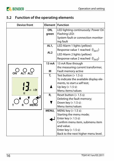
5.2 Function of the operating elements
Device front Element Function
ON,green
LED lighting continuously: Power OnFlashing LED:System fault or connection monitor-ing fault
AL1,
AL2
LED Alarm 1 lights (yellow): Response value 1 reached (IΔn1)LED Alarm 2 lights (yellow): Response value 2 reached (IΔn2)
13 mA
M
13 mA flow throughthe measuring current transformer,Fault memory active
T, Test button (> 1.5 s): To indicate the available display ele-ments, to start a self test; Up key (< 1.5 s): Menu items/values
R, Reset button (> 1.5 s): Deleting the fault memory; Down key (< 1.5 s): Menu items/values
MENU, MENU key (> 1.5 s):Starting the menu mode;Enter key (< 1.5 s):Confirm menu item, submenu item and value. Enter key (> 1.5 s):Back to the next higher menu level.
ON AL1 AL2
T MENUR
16 TGH1411en/03.2011

Operation and setting
5.3 Menu structureAll adjustable parameters are listed in the columns "menu item" and "adjusta-ble parameters". A display-like representation is used to illustrate the param-eters in the column menu item. Different alarm categories can be assigned to the alarm relays K1, K2 via the submenus r1, r2. This is done by activation or deactivation of the respective function.
MenuSub
MenuMenu item
Activa-tion
Adjustable parameter
AL(response -
values)
> I2 - (HI) IΔn2 (Alarm 2)
> I1 - (HI)IΔn1 as % of IΔn2(Alarm 1, prewarning)
Hys - Hysteresis IΔn1 / IΔn2
out(output con-
trol)
M ON Fault memory
1 - Operating mode K1 (n.c.)
2 - Operating mode K2 (n.c.)
RL -Reload function (memory = off )
r1(K1: (assign-ment alarm category)
1 Err ON Device error at K1
r1 I1 off Prewarning IΔn1 at K1
r1 I2 ON Alarm IΔn2 at K1
1 tES ON Device test
r2(K2: (assign-ment alarm category)
2 Err ON Device error at K2
r2 I1 off Prewarning IΔn1 at K2
r2 I2 ON Alarm IΔn2 at K2
2 tES ON Device test
17TGH1411en/03.2011
Operation and setting
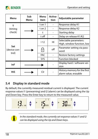
5.4 Display in standard modeBy default, the currently measured residual current is displayed. The current response values I1 (prewarning) and I2 (alarm) can be displayed using the Up and Down key. Press the Enter key to return to the measured value.
t(timing check)
t on 1 - Response delay K1
t on 2 - Response delay K2
t - Starting delay
t off - Delay on release K1/K2
Set(device con-
trol)
I 12 HISelectable parameters:High, window function, low
offParameter setting via pass-word
FAC - Restore factory settings
SYS - Function blocked
InF -Display hard / software ver-sion
HiS Clr -History memory for the first alarm value, erasable
In the standard mode, the currently set response values I1 and I2can be displayed using the Up and Down keys.
MenuSub
MenuMenu item
Activa-tion
Adjustable parameter
18 TGH1411en/03.2011

Operation and setting
5.5 Display in menu mode
5.5.1 Parameter query and setting: overview
Menu item
Adjustable parameter
AL Response values query and setting:– Residual current I2 (IΔn2) (AL2)– Residual current I1 (IΔn1) (AL1) – Hysteresis of the response values: % Hys
out Configuration of the fault memory and the alarm relays:– Activate/deactivate the fault memory or assign continu-
ous mode (on/off/con)– Select N/O operation (n.o.) or N/C operation (n.c.)
individually for each K1/K2– Specify the number of the reload cycles– Assign the alarm category I1 (IΔn1) or I2 (IΔn2), relay test
or device error individually to K1/K2 (1, r1/ 2, r2).
t Set delays:– Response delay ton1/ton2– Starting delay t– Delay on release toff (LED, relay)
SEt
Device control parameter setting:– Select the appropriate parameter for response values:
overcurrent mode (HI), undercurrent mode (Lo) or win-dow mode (In).
– Enable or disable password protection, change the pass-word.
– Restore factory settings.– Service menu SyS blocked
InF Query hard and software version
HiS Query the first stored alarm value
ESC Move to the next higher menu level (back)
19TGH1411en/03.2011

Operation and setting
Menu structure
���������
�������
��������
��������
���������
���������� !����"
���
20 TGH1411en/03.2011

Operation and setting
Parameter settingsAn example is given here on how to change the alarm response value I1 (IΔn1). It is presumed that the option overcurrent (HI) has been selected in the SEt/I 12 menu (factory setting). Proceed as follows:
1. Press the MENU/Enter key for more than 1.5 seconds. The flashing short symbol AL appears on the display.
2. Confirm with Enter. The parameter response value > I2 flashes, in addi-tion the associated overcurrent value > 30 mA appears.
3. Use the Down key to select the parameter response value I1. The parameter > I1 flashes, in addition the associated percentage value for prewarning 50 % of I2 appears.
4. Confirm with Enter. The current value for prewarning appears on the flashing display.
5. Use the Up or Down key to set the appropriate prewarning value. Con-firm with Enter. I1 flashes.
6. You can exit the menu by:– pressing the Enter key for more than 1.5 seconds to reach the next
higher level or– selecting the menu item ESC and confirming with Enter to reach the
next higher level.
5.5.2 Changeover from overcurrent to undercurrent mode or to win-dow mode
The operating mode can be changed in the SEt/I 12 menu using the parame-ters HI, Lo and In. By default, overcurrent operation (HI) is set. Refer to page 27 for a detailed description on how to change over to the window mode.
The currently active segments are flashing! In the figures below,the segments where device settings can be carried out are high-lighted by an oval. The menu mode can be reached by pressingthe MENU key for more than 1.5 seconds.
21TGH1411en/03.2011

Operation and setting
5.5.3 Response value setting for overcurrent:- Response value I2 (overcurrent IΔn2)- Response value I1 (overcurrent IΔn1)- Hysteresis (Hys) of the response values IΔn1, IΔn2
Increasing the response value I2 (alarm overcurrent)
Increasing the response value I1 (prewarning overcurrent).
Setting the hysteresis of the response value
�
�
22 TGH1411en/03.2011
Operation and setting
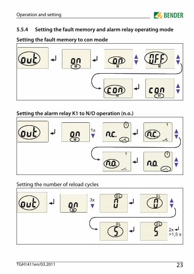
5.5.4 Setting the fault memory and alarm relay operating mode
Setting the fault memory to con mode
Setting the alarm relay K1 to N/O operation (n.o.)
Setting the number of reload cycles
�
������
�
23TGH1411en/03.2011
Operation and setting
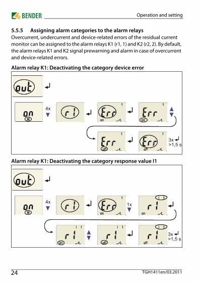
5.5.5 Assigning alarm categories to the alarm relaysOvercurrent, undercurrent and device-related errors of the residual current monitor can be assigned to the alarm relays K1 (r1, 1) and K2 (r2, 2). By default, the alarm relays K1 and K2 signal prewarning and alarm in case of overcurrent and device-related errors.
Alarm relay K1: Deactivating the category device error
Alarm relay K1: Deactivating the category response value I1
������
������
�
24 TGH1411en/03.2011
Operation and setting
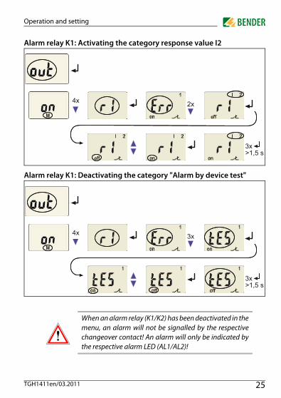
Alarm relay K1: Activating the category response value I2
Alarm relay K1: Deactivating the category "Alarm by device test"
When an alarm relay (K1/K2) has been deactivated in themenu, an alarm will not be signalled by the respectivechangeover contact! An alarm will only be indicated bythe respective alarm LED (AL1/AL2)!
������
�
������
�
25TGH1411en/03.2011

Operation and setting
5.5.6 Set the time delaysThe following delays can be set: Response delay ton1 (0...10 s) for K1, and ton2 (0...10 s) for K2 Starting delay t (0...10 s) when the device is being started Common delay on release toff (0...99 s) for K1, K2. The setting toff is only
relevant when the fault memory M is deactivated.
The operating steps for the setting of the response delay ton1 and the starting delay t are illustrated by way of example.
Setting the response delay ton1
Setting the starting delay t
������
������
�
26 TGH1411en/03.2011

Operation and setting
5.5.7 Changing from overcurrent operation to window operationUse this menu item to set whether the response values of the device apply to overcurrent (HI) or undercurrent operation (Lo). In addition, window opera-tion (In) can be selected.
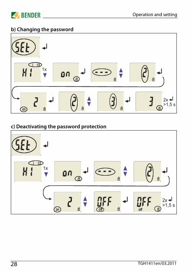
5.5.8 Factory setting and password protectionUse this menu to activate the password protection, to change the password or to deactivate the password protection. In addition, you can reset the device to its factory settings.
a) Activating the password protection
������
������
�
27TGH1411en/03.2011
Operation and setting
b) Changing the password
c) Deactivating the password protection
������
�
������
�
28 TGH1411en/03.2011
Operation and setting
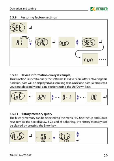
5.5.9 Restoring factory settings
5.5.10 Device information query (Example)This function is used to query the software (1.xx) version. After activating this function, data will be displayed as a scrolling text. Once one pass is completed you can select individual data sections using the Up/Down keys.
5.5.11 History memory queryThe history memory can be selected via the menu HiS. Use the Up and Down keys to view the next display. If Clr and M is flashing, the history memory can be cleared by pressing the Enter key.
�
����
���� ����
29TGH1411en/03.2011

Operation and setting
5.6 CommissioningPrior to commissioning, check proper connection of the residual current mon-itor.
5.7 Factory setting
Response value overcurrent I1 (prewarning)Response value overcurrent I2 (alarm)Hysteresis:Fault memory M:Operating mode K1/K2 Starting delay:Response delay:
Delay on release:Password:
15 mA (50 % of I2)30 mA15 %activated (on)N/C operation (n.c.)t = 0.5 ston1 = 1 ston2 = 0 stoff = 1 s0, deactivated (Off)
30 TGH1411en/03.2011

6. Technical data
6.1 Data in tabular form( )* = factory setting
Insulation coordination acc. to IEC 60664-1/IEC 60664-3Rated insulation voltage ....................................................................................................................................... 250 VRated impulse voltage/pollution degree ........................................................................................................ 2.5 kV / IIIProtective separation (reinforced insulation) between:.................................................................................................. ........................................................................................................... (A1, A2) - (k/l, T/R) - (11, 12, 14) - (21, 22, 24)Voltage test according to IEC 61010-1 ............................................................................................................... 2.21 kV
Supply voltageRCMA420-D-1:Supply voltage Us ............................................................................................................... AC 16...72 V / DC 9.6...94 VFrequency range Us ...................................................................................................................................... 42...460 HzRCMA420-D-2:Supply voltage Us ............................................................................................................................... AC/DC 70...300 VFrequency range Us ...................................................................................................................................... 42...460 HzPower consumption ............................................................................................................................................. ≤3 VA
Measuring circuitExternal measuring current transformer ..................................................................... W20AB, W35AB, W60AB series Rated insulation voltage (measuring current transformer) ................................................................................. 800 VOperating characteristic acc. to IEC 62020 and IEC/TR 60755 ........................................................................... Type BFrequency range .......................................................................................................................................... 0...2000 HzMeasuring range AC ......................................................................................................................................... 0...1.5 AMeasuring range DC ..................................................................................................................................... 0...600 mARelative uncertainty for f ≤ 2 Hz or ≥ 16 Hz .................................................................................................. 0...-35 %Relative uncertainty for f >2 Hz...<16 Hz ......................................................................................... -35 %...+100%Operating uncertainty ................................................................................................................................... 0...35 %
Response valuesRated residual operating current IΔn1 (prewarning, AL1) .............................................. 50...100 % x IΔn2, (50 %)*
31TGH1411en/03.2011

Technical data
Rated residual operating current IΔn2 (Alarm, AL2) ............................................................... 10...500 mA (30 mA)*Hysteresis .......................................................................................................................................... 10...25 % (15 %)*
Specified timeStarting delay t ...................................................................................................................................... 0...10 s (0.5 s)*Response delay ton2 (alarm) .................................................................................................................... 0...10 s (0 s)*Response delay ton1 (prewarning) .......................................................................................................... 0...10 s (1 s)*Delay on release toff .................................................................................................................................. 0...99 s (1 s)*Operating time tae at IΔn = 1 x IΔn1/2 .......................................................................................................... ≤ 180 msOperating time tae at IΔn = 5 x IΔn1/2 ............................................................................................................ ≤ 30 msResponse time tan .............................................................................................................................. tan = tae + ton1/2Recovery time tb ............................................................................................................................................. ≤ 300 ms
Displays, memoryDisplay range, measured value AC ................................................................................................................... 0...1.5 ADisplay range, measured value DC ............................................................................................................... 0...600 mAError of indication ......................................................................................................................... ± 17.5 % / ± 2 digitMeasured-value memory for alarm value ..................................................................... data record measured valuesPassword ........................................................................................................................................... off / 0...999 (off)*Fault memory alarm relay ........................................................................................................................ on / off (on)*
Inputs/outputsCable length for external test / reset button................................................................................................... 0…10 m
Cable lengths for measuring current transformersConnection WX... (see ordering information on page 35) ................................................... 1 m / 2.5 m / 5 m / 10 mor alternatively: single wire 6 x 0.75 mm2 ....................................................................................................... 0...10 m
Switching elementsNumber of switching elements ............................................................................................. 2 x 1 changeover contactOperating principle ............................................................................ N/C operation/N/O operation (N/C operation)*Electrical service life under rated operating conditions ................................................... 10 000 switching operationsContact data acc. to IEC 60947-5-1Utilization category .............................................................AC-13..........AC-14....... DC-12 .......... DC-12 .......... DC-12Rated operational voltage....................................................230 V ...........230 V .......... 24 V ........... 110 V ........... 220 VRated operational current ........................................................5 A...............3 A............ 1 A ............ 0.2 A ............ 0.1 AMinimum contact load ............................................................................................................. 1 mA at AC / DC ≥ 10 V
32 TGH1411en/03.2011

Technical data
Environment/EMCEMC ................................................................................................................................................................. IEC 62020Operating temperature ......................................................................................................................... -25 ºC...+55 ºC Classification of climatic conditions IEC 60721Stationary use (IEC 60721-3-3) ........................................................3K5 (except condensation and formation of ice)Transportation (IEC 60721-3-2) ........................................................2K3 (except condensation and formation of ice)Storage (IEC 60721-3-1) ...................................................................1K4 (except condensation and formation of ice)Classification of mechanical conditions acc. to IEC 60721:Stationary use (IEC 60721-3-3) .............................................................................................................................. 3M4Transportation (IEC 60721-3-2) .............................................................................................................................. 2M2Storage (IEC 60721-3-1) ......................................................................................................................................... 1M3
ConnectionConnection type.......................................................................................................... screw-type terminalsConnection properties:rigid/ flexible/ conductor sizes .......................................................................... 0.2...4 / 0.2...2.5 mm2 / AWG 24...12Multi-conductor connection (2 conductors with the same cross section):rigid, flexible ............................................................................................................................. 0.2...1.5 / 0.2...1.5 mm2
Stripping length ............................................................................................................................................... 8...9 mmTightening torque ....................................................................................................................................... 0.5...0.6 NmConnection type............................................................................................................ push-wire terminalsConnection properties:Rigid ............................................................................................................................... 0.2...2.5 mm2 ( AWG 24...14)Flexible without ferrules................................................................................................. 0.2...2.5 mm2 ( AWG 24...14)Flexible with ferrules ...................................................................................................... 0.2...1.5 mm2 ( AWG 24...16)Stripping length .................................................................................................................................................. 10 mmOpening force........................................................................................................................................................... 50 NTest opening, diameter....................................................................................................................................... 2.1 mm
OtherOperating mode ........................................................................................................................... continuous operationPosition of normal use .......................................................................................................................... display-orientedDegree of protection, internal components (IEC 60529) .........................................................................................IP30Degree of protection, terminals (IEC 60529) ............................................................................................................IP20Enclosure material .................................................................................................................................... polycarbonateFlammability class ............................................................................................................................................. UL94V-0
33TGH1411en/03.2011
Technical data
DIN rail mounting acc. to ................................................................................................................................. IEC 60715Screw fixing ......................................................................................................................... 2 x M4 with mounting clipSoftware version .......................................................................................................................................... D242 V1.2xWeight ............................................................................................................................................................... ≤ 150 g( )* = factory setting
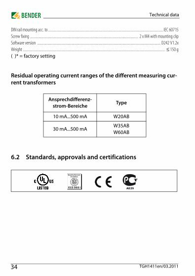
Residual operating current ranges of the different measuring cur-rent transformers
6.2 Standards, approvals and certifications
Ansprechdifferenz-strom-Bereiche
Type
10 mA...500 mA W20AB
30 mA...500 mAW35ABW60AB
34 TGH1411en/03.2011
Technical data
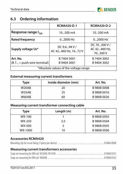
6.3 Ordering information
External measuring current transformers
Measuring current transformer connecting cable
Accessories RCMA420Mounting clip for screw fixing (1 piece per device) ................................................................................. B 9806 0008
Measuring current transformers accessoriesSnap-on mounting for DIN rail: W20AB /W35AB ................................................................................... B 9808 0501Snap-on mounting for DIN rail: W60AB .................................................................................................... B 9808 0502
RCMA420-D-1 RCMA420-D-2
Response range IΔn 10...500 mA 10...500 mA
Rated frequency 0...2000 Hz 0...2000 Hz
Supply voltage Us*DC 9.6...94 V /
AC 42...460 Hz, 16...72 V
DC 70...300 V / AC 42...460 Hz,
70...300 V
Art. No. (B 7... = push-wire terminal)
B 7404 3001B 9404 3001
B 7404 3002B 9404 3002
*Absolute values of the voltage range
Type Inside diameter (mm) Art. No.
W20AB 20 B 9808 0008W35AB 35 B 9808 0016W60AB 60 B 9808 0026
Type Length (m) Art. No.
WX-100 1 B 9808 0503WX-250 2,5 B 9808 0504WX-500 5 B 9808 0505
WX-1000 10 B 9808 0506
35TGH1411en/03.2011

Technical data
6.4 Error codesShould, contrary to all expectations, a device error occur, error codes will ap-pear on the display. Typical error codes are described below:
Error code Meaning:
E.01
Fault CT connection monitoringAppropriate action:Check CT connection for short-circuit or inter-ruption. After eliminating the fault, the error code will be automatically deleted.
E.02
Fault CT connection monitoring during manual self test.Appropriate action:Check CT connection for short-circuit or inter-ruption. After eliminating the fault and anew self-test or anew device start, the error code will be automatically deleted.
E....
Appropriate action when error codes > 02 occur:Appropriate action:Carry out a reset. Reset the device to factory setting. After eliminating the fault, the error code will be automatically deleted.If the fault continues to exist, please contact the BENDER Service.
36 TGH1411en/03.2011

INDEX
AAdjustable parameters, list 17Automatic self test 10
CConnection of an additional cascaded meas-
uring current transformer 15
DDelay on release toff 11Deleting the fault alarms 16Device features 9Display elements in use 15Display in standard mode 18
EENTER key 16Error codes 36Example of parameter setting 21
Ffactory setting 12, 30Function 9Functional faults 10
IInstallation and connection 13
KK1/K2: assignment alarm category 17
LLED Alarm 1 lights 16LED Alarm 2 lights 16
MManual self test 10Manual, target group 5Menu
- AL (response values) 17- HiS (history memory for the first
alarm value) 18- InF (hard and software version) 18- out (output control) 17- Set (device control 18- t (timing check) 18
Menu structure, overview 17
NNotes for the user 5
OOperating elements, function 16Operation and setting 15Ordering information 35
37TGH1411en/03.2011
PParameter query and setting, overview 19Parameter setting
- Activating or deactivating the pass-word protection 27
- Assigning alarm categories to the alarm relays 24
- Changeover from overcurrent opera-tion to window operation 27
- Set response values 22- Set the time delays 26
Password protection 12
RReset button 16Residual current monitoring in window dis-
criminator mode 12Residual operating current ranges of the dif-
ferent measuring current transformers 34
Response delay ton 11
SSelect the appropriate parameter for re-
sponse values- 19
Set response values- Hysteresis 22- Overcurrent (> I) 22
Setting the number of reload cycles 23Starting delay t 11Starting the menu mode 16
TTechnical data 31Test button 16
WWindow operation 27Wiring diagram 14Work activities on electrical installations 7
38 TGH1411en/03.2011


Dipl.-Ing. W. Bender GmbH & Co. KGLondorfer Str. 65 • 35305 Grünberg • GermanyPostfach 1161 • 35301 Grünberg • Germany
Tel.: +49 6401 807-0Fax: +49 6401 807-259
E-Mail: [email protected]: http://www.bender-de.com