Embed Size (px)
Citation preview

EGR7137502
E76Ver. 5.02
Programming ManualRCX Series


Introduction
Our sincere thanks for your purchase of this YAMAHA RCX series robot controller.
This manual describes robot program commands and related information for using YAMAHA RCX
series robot controllers. Be sure to read this manual carefully as well as related manuals and comply
with their instructions for using the YAMAHA robot controllers safely and correctly.
For details on how to operate YAMAHA robot controllers, refer to the separate controller user's
manual that comes with the YAMAHA robot controller.
Applicable controllers: RCX240, RCX141, RCX142, RCX40, RCX221 and RCX222
Model names as used in this manual include the following controllers.
RCX240 ... Includes RCX240, RCX141, RCX142 and RCX40 (4-axis controllers)
RCX14x ... Includes RCX141, RCX142 and RCX40 (4-axis controllers excluding RCX240)*
RCX22x ... Includes RCX221 and RCX222 (2-axis controllers)
* Here, "RCX14x" does not include RCX240 and is used when there is a difference between the
RCX240 and other 4-axis controllers due to differences in software versions.

Safety precautions
Be sure to read before using
Before using the YAMAHA robot controller, be sure to read this manual and related manuals, and
follow their instructions to use the robot controller safely and correctly.
Warning and caution items listed in this manual relate to YAMAHA robot controllers.
When this robot controller is used in a robot controller system, please take appropriate safety
measures as required by the user’s individual system.
This manual classifies safety caution items and operating points into the following levels, along with
symbols for signal words “CAUTION” and “NOTE”.
c CAUTION
"CAUTION" indicates a potentially hazardous situation which, if not avoided, could
result in minor or moderate injury or damage to the equipment or software.
n NOTE
Primarily explains function differences, etc., between software versions.
Explains robot operation procedures in a simple and clear manner.
Note that the items classified into “CAUTION” might result in serious injury depending on the
situation or environmental conditions. So always comply with CAUTION instructions since these
are essential to maintain safety.
Keep this manual carefully so that the operator can refer to it when needed. Also make sure that this
manual reaches the end user.
■ System design precautions
c CAUTION
When the program execution stops before it is complete, the program re-executes the
command that has stopped. Keep this point in mind when re-executing the program,
for example, when using an arch motion with the MOVE command, a relative
movement command such as the MOVEI or DRIVEI command, or a communication
command such as the SEND command.
MEMO

CONTENTS RCX SeriesProgramming Manual
T-1
Chapter 1 Writing Programs
1 The YAMAHA Robot Language 1-1
2 Characters 1-1
3 Program Basics 1-1
4 Program Names 1-2
5 Identifiers 1-7
6 Comment 1-7
7 Command Statement Format 1-8
Chapter 2 Constants
1 Outline 2-1
2 Numeric constants 2-1
2.1 Integer constants 2-1
2.2 Real constants 2-1
3 Character constants 2-2
Chapter 3 Variables
1 Outline 3-1
2 User Variables & System Variables 3-2
2.1 User Variables 3-2
2.2 System Variables 3-2
3 Variable Names 3-3
3.1 Dynamic Variable Names 3-3
3.2 Static Variable Names 3-3
4 Variable Types 3-4
4.1 Numeric variables 3-4
4.2 Character variables 3-4
5 Array variables 3-5
6 Value Assignments 3-5

CONTENTS RCX SeriesProgramming Manual
T-2 T-3
7 Type Conversions 3-6
8 Value Pass-Along & Reference Pass-Along 3-6
9 System Variables 3-7
9.1 Point data variable 3-7
9.2 Shift coordinate variable 3-8
9.3 Point element variable 3-9
9.4 Shift element variable 3-10
9.5 Parallel input variable 3-10
9.6 Parallel output variable 3-11
9.7 Internal output variable 3-12
9.8 Arm lock output variable 3-13
9.9 Timer output variable 3-14
9.10 Serial input variable 3-15
9.11 Serial output variable 3-16
9.12 Serial word input 3-17
9.13 Serial double word input 3-17
9.14 Serial word output 3-18
9.15 Serial double word output 3-18
10 Bit Settings 3-19
11 Valid range of variables 3-20
11.1 Valid range of dynamic variables 3-20
11.2 Valid range of static variables 3-20
11.3 Valid range of dynamic array variables 3-20
12 Clearing variables 3-21
12.1 Clearing dynamic variables 3-21
12.2 Clearing static variables 3-21
Chapter 4 Expressions and Operations
1 Arithmetic operations 4-1
1.1 Arithmetic operators 4-1
1.2 Relational operators 4-1
1.3 Logic operations 4-2
1.4 Priority of arithmetic operation 4-3
1.5 Data format conversion 4-3
2 Character string operations 4-4
2.1 Character string connection 4-4
2.2 Character string comparison 4-4

T-2
CONTENTS RCX SeriesProgramming Manual
T-3
3 Point data format 4-5
4 DI/DO conditional expressions 4-6
Chapter 5 Multiple Robot Control
1 Overview 5-1
2 Command list for each group 5-2
Chapter 6 Multi-tasking
1 Outline 6-1
2 Taskdefinition 6-1
3 Task status and transition 6-2
3.1 Starting tasks 6-2
3.2 Task scheduling 6-3
3.3 Condition wait in task 6-4
3.4 Suspending tasks (SUSPEND) 6-5
3.5 Restarting tasks (RESTART) 6-5
3.6 Deleting tasks 6-6
3.7 Stopping tasks 6-7
4 Multi-task program example 6-8
5 Sharing the data 6-8
6 Cautionary Items 6-9
Chapter 7 Sequence function
1 Sequence function 7-1
2 Creating a sequence program 7-1
2.1 Programming method 7-1
2.2 Compiling 7-2
3 Executing a sequence program 7-4
3.1 Sequence program STEP execution 7-4
4 Creating a sequence program 7-5
4.1 Assignment statements 7-5
4.2 Input/output variables 7-5

CONTENTS RCX SeriesProgramming Manual
T-4 T-5
4.3 Timerdefinitionstatement 7-7
4.4 Logical operators 7-7
4.5 Priority of logic operations 7-8
4.6 Sequenceprogramspecifications 7-8
Chapter 8 Robot Language Lists
How to read the robot language table 8-1
Command list in alphabetic order 8-3
FunctionSpecific 8-8
Functions: in alphabetic order 8-15
Functions:operation-specific 8-18
1 ABS Acquires absolute values 8-20
2 ABSINIT / ABSINIT2 Resets the current position of a specified axis 8-21
3 ABSRPOS / ABSRPOS2 Acquires a machine reference 8-23
4 ABSRST Absolute motor axis return-to-origin operation 8-24
5 ACCEL / ACCEL2 Specifies/acquires the acceleration coefficient parameter 8-25
6 ARCH / ARCH2 Specifies/acquires the acceleration coefficient parameter 8-26
7 ARMCND / ARMCND2 Arm status acquisition 8-28
8 ARMTYPE / ARMTYPE2 SCARA robot hand system 8-29
9 ATN / ATN2 Acquires the arctangent of the specified value 8-30
10 ASPEED / ASPEED2 Sets the automatic movement speed 8-31
11 AXWGHT / AXWGHT2 Sets/acquires the axis tip weight 8-32
12 CALL Calls a sub-procedure 8-33
13 CHANGE / CHANGE2 Switches the hand 8-34
14 CHGPRI Changes the priority ranking of a specified task 8-35
15 CHR$ Acquires a character with the specified character code 8-36
16 COS Acquires the cosine value of a specified value 8-37
17 CURTRQ / CURTRQ2 Acquires the current torque of the specified axis 8-37
18 CUT Terminates another sub task which is currently being executed 8-38
19 DATE$ Acquires the date 8-39
20 DECEL / DECEL2 Specifies/acquires the deceleration rate parameter 8-40
21 DECLARE Declares that a sub-routine or sub-procedure is to be used within the COMMON program
8-41
22 DEF FN Defines functions which can be used by the user 8-43

T-4
CONTENTS RCX SeriesProgramming Manual
T-5
23 DEGRAD Angle conversion (angle → radian) 8-44
24 DELAY Program execution waits for a specified period of time 8-45
25 DI Acquires the input status from the parallel port 8-46
26 DIST Acquires the distance between 2 specified points 8-47
27 DIM Declares array variable 8-48
28 DO Outputs to parallel port 8-49
29 DRIVE / DRIVE2 Executes absolute movement of specified axes 8-50
30 DRIVEI / DRIVEI2 Moves the specified robot axes in a relative manner 8-58
31 END SELECT Ends the SELECT CASE statement 8-63
32 END SUB Ends the sub-procedure definition 8-64
33 ERR / ERL Acquires the error code / error line No 8-65
34 EXIT FOR Terminates the FOR to NEXT statement loop 8-66
35 EXIT SUB Terminates the sub-procedure defined by SUB to END 8-67
36 EXIT TASK Terminates its own task which is in progress 8-68
37 FOR to NEXT Performs loop processing until the variable-specified value is exceeded 8-69
38 GOSUB to RETURN Jumps to a sub-routine 8-70
39 GOTO Executes an unconditional jump to the specified line 8-71
40 HALT Stops the program and performs a reset 8-72
41 HAND / HAND2 Defines the hand 8-73
41.1 For SCARA Robots 8-73
41.2 For Cartesian Robots 8-76
42 HOLD Temporarily stops the program 8-78
43 IF Evaluates a conditional expression value, and executes the command in accordance with the conditions
8-79
43.1 Simple IF statement 8-79
43.2 Block IF statement 8-80
44 INPUT Assigns a value to a variable specified from the programming box 8-81
45 INT Truncates decimal fractions 8-82
46 JTOXY / JTOXY2 Performs axis unit system conversions (pulse → mm) 8-83
47 LABEL Statement Defines labels at program lines 8-84
48 LEFT$ Extracts character strings from the left end 8-85
49 LEFTY / LEFTY2 Sets the SCARA robot hand system as a left-hand system 8-86
50 LEN Acquires a character string length 8-87
51 LET Assigns values to variables 8-88
52 LO Arm lock output 8-91
53 LOCx Specifies/acquires point data or shift data for a specified axis 8-92

CONTENTS RCX SeriesProgramming Manual
T-6 T-7
54 LSHIFT Left-shifts a bit 8-94
55 MCHREF / MCHREF2 Acquires a machine reference 8-95
56 MID$ Acquires a character string from a specified position 8-96
57 MO Outputs a specified value to the MO port (internal output) 8-97
58 MOVE / MOVE2 Performs absolute movement of all robot axes 8-98
59 MOVEI / MOVEI2 Performs absolute movement of all robot axes 8-114
60 OFFLINE Sets a specified communication port to the "offline" mode 8-119
61 ORD Acquires a character code 8-120
62 ON ERROR GOTO Jumps to a specified label when an error occurs 8-121
63 ON to GOSUB Executes the subroutine specified by the <expression> value 8-122
64 ON to GOTO Jumps to the label specified by the <expression> value 8-123
65 ONLINE Sets the specified communication port to the "online" mode 8-124
66 ORGORD / ORGORD2 Specifies/acquires the robot's return-to-origin sequence 8-125
67 ORIGIN Performs an incremental mode axis return-to-origin 8-126
68 OUT Turns ON the specified port output 8-127
69 OUTPOS / OUTPOS2 Specifies/acquires the OUT enable position parameter of the robot 8-128
70 PATH Specifies the main robot axis PATH motion path 8-130
71 PATH END Ends the movement path setting 8-136
72 PATH SET Starts the movement path setting 8-137
73 PATH START Starts the PATH motion 8-139
74 PDEF Defines the pallet used to execute pallet movement commands 8-140
75 PMOVE / PMOVE2 Executes a pallet movement command for the robot 8-141
76 Pn Defines points within a program 8-145
77 PPNT Creates pallet point data 8-147
78 PRINT Displays the specified expression value at the programming box 8-148
79 RADDEG Performs a unit conversion (radians → degrees) 8-149
80 REM Inserts a comment 8-150
81 RESET Turns OFF the bits of specified ports, or clears variables 8-151
82 RESTART Restarts another task during a temporary stop 8-152
83 RESUME Resumes program execution after error recovery processing 8-153
84 RETURN Processing which was branched by GOSUB, is returned to the next line after GOSUB
8-154
85 RIGHT$ Extracts a character string from the right end of another character string 8-155
86 RIGHTY / RIGHTY2 Sets the SCARA robot hand system to "Right" 8-156
87 RSHIFT Shifts a bit value to the right 8-157
88 Sn Defines the shift coordinates in the program 8-158

T-6
CONTENTS RCX SeriesProgramming Manual
T-7
89 SELECT CASE Executes the specified command block in accordance with the <expression> value
8-159
90 SEND Sends <read file> data to the <write file> 8-160
91 SERVO / SERVO2 Controls the servo status 8-162
92 SET Turns the bit at the specified output port ON 8-163
93 SHARED Enables sub-procedure referencing without passing on the variable 8-164
94 SHIFT / SHIFT2 Sets the shift coordinates 8-165
95 SIN Acquires the sine value for a specified value 8-166
96 SO Outputs a specified value to the serial port 8-167
97 SPEED / SPEED2 Changes the program movement speed 8-168
98 START Starts a new task 8-169
99 STR$ Converts a numeric value to a character string 8-170
100 SQR Acquires the square root of a specified value 8-171
101 SUB to END SUB Defines a sub-procedure 8-172
102 SUSPEND Temporarily stops another task which is being executed 8-174
103 SWI Switches the program being executed 8-175
104 TAN Acquires the tangent value for a specified value 8-176
105 TCOUNTER Timer & counter 8-177
106 TIME$ Acquires the current time 8-178
107 TIMER Acquires the current time 8-179
108 TO Outputs a specified value to the TO port 8-180
109 TOLE / TOLE2 Specifies/acquires the tolerance parameter 8-181
110 TORQUE / TORQUE2 Specifies/acquires the maximum torque command value which can be set for a specified axis
8-182
111 TRQSTS / TRQSTS2 Acquires the status when DRIVE statement ends 8-184
112 TRQTIME / TRQTIME2 Sets/acquires the time-out period for the torque limit setting option 8-185
113 VAL Converts character strings to numeric values 8-187
114 WAIT Waits until the conditions of the DI/DO conditional expression are met 8-188
115 WAIT ARM / WAIT ARM2 Waits until the robot axis operation is completed 8-189
116 WEIGHT/WEIGHT2 Specifies/acquires the tip weight parameter 8-190
117 WEND Ends the WHILE statement's command block 8-191
118 WHERE / WHERE2 Acquires the arm's current position (pulse coordinates) 8-192
119 WHILE to WEND Repeats an operation for as long as a condition is met 8-193
120 WHRXY / WHRXY2 Acquires the arm's current position in Cartesian coordinates 8-194
121 XYTOJ / XYTOJ2 Converts the main group axes Cartesian coordinate data ("mm") to joint coordinate data ("pulse")
8-195
122 _SYSFLG Axis status monitoring flag 8-195

CONTENTS RCX SeriesProgramming Manual
T-8 T-9
Chapter 9 PATH Statements
1 Overview 9-1
2 Features 9-1
3 How to use 9-1
4 Cautions when using this function 9-2
Chapter 10 Limitless motion
1 Overview 10-1
2 Operation Procedure 10-1
2.1 Parameters 10-1
2.2 Robot language 10-1
2.3 Sample program 10-2
3 Restrictions 10-3
Chapter 11 Datafiledescription
1 Overview 11-1
1.1 Datafiletypes 11-1
1.2 Cautions 11-1
2 Programfile 11-2
2.1 All programs 11-2
2.2 One program 11-3
3 Pointfile 11-4
3.1 All points 11-4
3.2 One point 11-6
4 Pointcommentfile 11-8
4.1 All point comments 11-8
4.2 One point comment 11-8
5 Parameterfile 11-10
5.1 All parameters 11-10
5.2 One parameter 11-12
6 Shiftcoordinatedefinitionfile 11-13
6.1 All shift data 11-13
6.2 Oneshiftdefinition 11-14

T-8
CONTENTS RCX SeriesProgramming Manual
T-9
7 Handdefinitionfile 11-15
7.1 All hand data 11-15
7.2 Onehanddefinition 11-16
8 Palletdefinitionfile 11-17
8.1 Allpalletdefinitions 11-17
8.2 Onepalletdefinition 11-20
9 Allfile 11-23
9.1 Allfiles 11-23
10 Programdirectoryfile 11-24
10.1 Entire program directory 11-24
10.2 One program 11-25
11 Parameterdirectoryfile 11-26
11.1 Entire parameter directory 11-26
12 Variablefile 11-27
12.1 All variables 11-27
12.2 One variable 11-29
13 Constantfile 11-30
13.1 One character string 11-30
14 Arrayvariablefile 11-31
14.1 All array variables 11-31
14.2 One array variable 11-32
15 DIfile 11-33
15.1 All DI information 11-33
15.2 One DI port 11-34
16 DOfile 11-35
16.1 All DO information 11-35
16.2 One DO port 11-36
17 MOfile 11-37
17.1 All MO information 11-37
17.2 One MO port 11-38
18 LOfile 11-39
18.1 All LO information 11-39
18.2 One LO port 11-40

CONTENTS RCX SeriesProgramming Manual
T-10 T-11
19 TOfile 11-41
19.1 All TO information 11-41
19.2 One TO port 11-42
20 SIfile 11-43
20.1 All SI information 11-43
20.2 One SI port 11-44
21 SOfile 11-45
21.1 All SO information 11-45
21.2 One SI port 11-46
22 Errormessagehistoryfile 11-47
22.1 All error message history 11-47
23 Error Message History Details File 11-48
23.1 General error message history details 11-48
24 Machinereferencefile 11-49
24.1 Allmachinereferencefile 11-49
25 EOFfile 11-50
25.1 EOF data 11-50
26 Serialportcommunicationfile 11-51
26.1 Serialportcommunicationfile 11-51
27 SIWfile 11-52
27.1 All SIW 11-52
27.2 One SIW data 11-53
28 SOWfile 11-54
28.1 All SIW 11-54
28.2 One SOW data 11-55
29 Ethernetportcommunicationfile 11-56
29.1 Ethernetportcommunicationfile 11-56
Chapter 12 User program examples
1 Basic operation 12-1
1.1 Directly writing point data in program 12-1

T-10
CONTENTS RCX SeriesProgramming Manual
T-11
1.2 Using point numbers 12-2
1.3 Using shift coordinates 12-3
1.4 Palletizing 12-4
1.4.1 Calculating point coordinates 12-4
1.4.2 Utilizing pallet movement 12-6
1.5 DI/DO (digital input and output) operation 12-7
2 Application 12-8
2.1 Pick and place between 2 points 12-8
2.2 Palletizing 12-10
2.3 Pick and place of stacked parts 12-12
2.4 Parts inspection (Multi-tasking example) 12-14
2.5 Sealing 12-17
2.6 Connection to an external device through RS-232C (example 1) 12-18
2.7 Connection to an external device through RS-232C (example 2) 12-19
Chapter 13 Online commands
1 Online Command List 13-1
1.1 Onlinecommandlist:Functionspecific 13-1
1.2 Online command list: In alphabetic order 13-4
2 Key operation 13-6
2.1 Changing the mode 13-6
2.2 AUTO mode operation 13-7
2.3 MANUAL mode operation 13-9
3 Utility operation 13-12
3.1 Acquiring the program execution status 13-12
3.2 Copy 13-12
3.3 Erase 13-14
3.4 Rename program name 13-16
3.5 Changing the program attribute 13-16
3.6 Initialize 13-17
3.7 Setting the display language 13-18
3.8 Setting the coordinates and units in MANUAL mode 13-19
3.9 Clearing the programming box error message 13-19
3.10 Setting the UTILITY mode 13-20
3.11 Checking and setting the date 13-22
3.12 Checking and setting the time 13-23
4 Data handling 13-24
4.1 Acquiring the display language 13-24
4.2 Acquiring the access level 13-24

CONTENTS RCX SeriesProgramming Manual
T-12 T-13
4.3 Acquiring the arm status 13-25
4.4 Acquiring the break point status 13-25
4.5 Acquiringthecontrollerconfigurationstatus 13-26
4.6 Acquiring the execution level 13-26
4.7 Acquiring the mode status 13-27
4.8 Acquiring the message 13-28
4.9 Acquiring return-to-origin status 13-29
4.10 Acquiring the absolute reset status 13-29
4.11 Acquiring the servo status 13-30
4.12 Acquiring the sequence program execution status 13-30
4.13 Acquiring the speed setting status 13-31
4.14 Acquiring the point coordinates and units 13-31
4.15 Acquiring the version information 13-32
4.16 Acquiring the current positions 13-32
4.17 Acquiring the tasks in RUN or SUSPEND status 13-34
4.18 Acquiring the tasks operation status 13-35
4.19 Acquiring the shift status 13-35
4.20 Acquiring the hand status 13-36
4.21 Acquiring the remaining memory capacity 13-36
4.22 Acquiring the emergency stop status 13-37
4.23 Acquiring the error status by self-diagnosis 13-37
4.24 Acquiring the option slot status 13-38
4.25 Acquiring various values 13-39
4.26 Data readout processing 13-41
4.27 Data write processing 13-42
4.28 Current torque value acquisition 13-43
5 Executing the robot language independently 13-44
5.1 Switching the program 13-44
5.2 Other robot language command processing 13-45
6 Control codes 13-46
6.1 Interrupting the command execution 13-46
Chapter 14 IO commands
1 Overview 14-1
2 IO command format 14-1
3 Sending and receiving IO commands 14-3
4 IO command list 14-5

T-12
CONTENTS RCX SeriesProgramming Manual
T-13
5 IO command description 14-6
5.1 MOVE command 14-6
5.2 MOVEI command 14-7
5.3 Pallet movement command 14-7
5.4 Jog movement command 14-8
5.5 Inching movement command 14-8
5.6 Point teaching command 14-9
5.7 Absolute reset movement command 14-9
5.8 Absolute reset command 14-10
5.9 Return-to-origin command 14-10
5.10 Servo command 14-11
5.11 Manual movement speed change command 14-12
5.12 Auto movement speed change command 14-12
5.13 Program speed change command 14-12
5.14 Shift designation change command 14-13
5.15 Hand designation change command 14-13
5.16 Arm designation change command 14-13
5.17 Point display unit designation command 14-13
Chapter 15 Appendix
1 Reserved word list 15-1
2 Robot Language Lists: Command list in alphabetic order 15-3
3 RobotLanguageLists:FunctionSpecific 15-8
4 Functions: in alphabetic order 15-15
5 Functions:operation-specific 15-18
6 Execution Level 15-20
Index


Chapter 1
Writing Programs
1 1 The YAMAHA Robot Language ................1-1
2 2 Characters ................................................1-1
3 3 Program Basics .........................................1-1
4 4 Program Names ........................................1-2
5 5 Identifiers ...................................................1-7
6 6 Comment ..................................................1-7
7 7 Command Statement Format .................1-8


1
2
3
4
5
6
7
The YAMAHA Robot Language 1-1
1 The YAMAHA Robot Language
The YAMAHA robot language was developed by Yamaha Motor Co., Ltd. IM Company for simple
and efficient programming to control YAMAHA industrial robots. The YAMAHA robot language is
similar to BASIC (Beginner’s All-purpose Symbolic Instruction Code) and makes even complex robot
movements easy to program. This manual explains how to write robot control programs with the
YAMAHA robot language, including actual examples on how its commands are used.
2 Characters
The characters and symbols used in the YAMAHA robot language are shown below.
Only 1-byte characters can be used.
Alphabetic characters •
A to Z, a to z
Numbers •
0 to 9
Symbols •
( ) [ ] + - * / ^ = < > & | ~ _ % ! # $ : ; , . " ' @ ?
katakana (Japanese phonetic characters • )
•Katakana (Japanese phonetic characters) cannot be entered from a programming box. Katakana
can be used when communicating with a host computer (if it handles katakana).
•Spacesarealsocountedascharacters(1space=1character).
3 Program Basics
Programs are written in a "1 line = 1 command" format, and every line must contain a command.
Blank lines (lines with no command) will cause an error when the program is compiled (creation of
execution objects). The program's final line, in particular, must not be blank.
To increase the program's efficiency, processes which are repeated within the program should be
written as subroutines or sub-procedures which can be called from the main routine. Moreover,
same processing items which occurs in multiple programs should be written as common routines
within a program named [COMMON], allowing those processing items to be called from multiple
programs.
User functions can be defined for specific calculations. Defined user functions are easily called,
allowing even complex calculations to be easily performed.
Multi-task programs can also be used to execute multiple command statements simultaneously in a
parallel processing manner.
Using the above functions allows easy creation of programs which perform complex processing.
MEMO
n NOTE
For sub-procedure details, •refer to the "CALL" and "SUB ~ END SUB" items.
n NOTE
For details regarding user •defined functions, refer to the "DEF FN" item.

1-2 Chapter 1 Writing Programs
1
2
3
4
5
6
7
4 Program Names
Each program to be created in the robot controller must have its own name.
Programs can be named as desired provided that the following conditions are satisfied:
Program names may contain no more than 8 characters, comprising a combination of ■
alphanumeric characters and underscores (_).
Each program must have a unique name (no duplications). ■
The 4 program names shown below are reserved for system operations, and programs with these
names have a special meaning.
FUNCTION A)
SEQUENCEB)
_SELECTC)
COMMOND)
The functions of these programs are explained below.
A) FUNCTION
Functions Pressing the USER key in “PROGRAM” mode or “MANUAL” mode allows the
user function to be used. When user functions are used in the "PROGRAM" mode,
commands (MOVE, GOTO, etc.) which are frequently used during program editing can
be entered by function keys. When used in “MANUAL” mode, DO output is available
with the function keys without running the program. The FUNCTION program defines
function keys which are used to execute user functions. The desired functions can be
freely assigned to the function keys.
SAMPLE
’FOR MANUAL MODE*M_F1:’DO(20)ALTERNATE DO(20)=~DO(20) ・・・・・・・・・・・・・ DO (20) ON/OFF highlighting
occurs when the key is pressed.*M_F2:’DO(21)ALTERNATE DO(21)=~DO(21) ・・・・・・・・・・・・・ DO (21) is highlighted. :*M_F6:’DO(25)MOMENTARY DO(25)=1 ・・・・・・・・・・・・・・・・・・・・・・・ DO (25) is set to "1" when the key is pressed. DO(25)=0 ・・・・・・・・・・・・・・・・・・・・・・・ DO (25) is set to "0" when the key is released.*M_F7:’MOTION MOVE P,P1 ・・・・・・・・・・・・・・・・・・・・・ Movement to Point 1 occurs. MOVE P,P2 ・・・・・・・・・・・・・・・・・・・・・ Movement to Point 2 occurs. :’FOR PROGRAM MODE *P_F1:’MOVE P, ・・・・・・・・・・・・・・・・・ [MOVE P,] is written to the
program when the key is pressed.*P_F6:’MOVE L, ・・・・・・・・・・・・・・・・・ [MOVE L,] is written to the
program when the key is pressed.*P_F2:’GOTO * ・・・・・・・・・・・・・・・・・・・ [GOTO *] is written to the
program when the key is pressed. :

1
2
3
4
5
6
7
Program Names 1-3
● Registering editing function keys used in the PROGRAM mode
Format
*P_F <n>: ' <character string>
Values <n> .......................................Denotes the No. of the function key being registered
(n = 1 to 15).
<character string> ..................The character string which is registered and displayed
for the function key.
•Although up to 65 characters can be entered for a <character string>, no more than 7 characters
are displayed on the Menu.
SAMPLE
*P_F2:’MOVE P, ・・・・・・・・・・・・・・ Registers "MOVE P," at the [F2] key.
*P_F8:’DELAY ・・・・・・・・・・・・・・・・・ Registers "DELAY" at the [F8] key.
Registering output command function keys used in the MANUAL mode ●
Format
*M_F <n>:' <character string><Output statement 1><Output statement 2>
Values <n> ........................................Denotes the No. of the function key being registered
(n = 1 to 15).
<character string> ..................The character string which is displayed for the function
key.
<Input/output statement 1> ....Command statement which is executed when the key
is pressed.
<Input/output statement 2> ....Command statement which is executed when the key
is released
•Although up to 65 characters can be entered for a <character string>, no more than 7 characters
are displayed on the Menu.
SAMPLE
*M_F2:'MOMENT ・・・・・・・・・・・・・・・ Displays "MOMENT" at the [F2] key.
DO(20)=1 ・・・・・・・・・・・・・・・・・・・・・・・ DO (20) is turned ON when the [F2] key is pressed.
DO(20)=0 ・・・・・・・・・・・・・・・・・・・・・・・ DO (20) is turned OFF when the [F2] key is released.
*M_F14:'ALTER ・・・・・・・・・・・・・・・ Displays "ALTER" at the [F14] key.
DO(20)=~DO(20) ・・・・・・・・・・・・・・ The DO(20) output status is highlighted when the [F14] key is pressed.
REFERENCE For details, refer to the relevant controller manual.
MEMO
MEMO

1-4 Chapter 1 Writing Programs
1
2
3
4
5
6
7
B) SEQUENCE
Functions Unlike standard robot programs, the RCX Controller allows the execution of high-speed-
processing programs (sequence programs) in response to robot inputs and outputs (DI,
DO, MO, LO, TO, SI, SO). Specify a program name of "SEQUENCE" to use this function,
thus creating a pseudo PLC within the controller.
When the controller is in the AUTO or MANUAL mode, a SEQUENCE program can
be executed in fixed cycles (regardless of the program execution status) in response
to dedicated DI10 (sequence control input) input signals, with the cycle being
determined by the program capacity. For details, see Chapter 7 "4.6 Sequence program
specifications".
This allows sensors, push-button switches, and solenoid valves, etc., to be monitored
and operated by input/output signals.
Moreover, because the sequence programs are written in robot language, they can
easily be created without having to use a new and unfamiliar language.
SAMPLE
DO(20)=~DI(20) DO(25)=DI(21) AND DI(22) MO(26)=DO(26) OR DO(25) :
REFERENCE For details, see Chapter 7 "Sequence function".

1
2
3
4
5
6
7
Program Names 1-5
C)_SELECT
Functions This function allows the user to create a program which is always selected and executed
when the robot program is reset. Specify a program name of "_SELECT" to use this
function. For example, if multiple programs exist, and there is a need to switch between
the programs by using DI inputs, simply create a program-switching program named "_
SELECT". Even if another program is running, the system always returns to this program
when a reset input occurs after that program stops. The various reset types and their
corresponding processing are as follows (also refer to the program example shown
below):
1. When a reset is executed from the Programming Box, a query displays, asking if
a change to "_SELECT" is desired. If "No" is pressed, a selection screen displays,
allowing the user to select whether or not a reset is to be executed.
2. When reset by the HALT command in a program, dedicated DI (reset signal) or
online command, the system switches to the "_SELECT" program.
3. The operation which occurs at power ON varies according to the "execution level".
If the execution level has been selected as "execute program reset at power ON", a
reset is executed at power ON, and "_SELECT" is then selected.
A program is selected according to the value input from DI3( ).
When DI3( ) is 0, the system repeatedly monitors the DI input.
When DI3( ) is from 1 to 3, the matching program is selected.
When DI3( ) is other than the above cases, the system quits the program that is
currently running.
SAMPLE
ON ERROR GOTO *ER1 *ST: SELECT CASE DI3( ) ・・・・・ Branching occurs based on the DI3 "( )" value. CASE 0 GOTO *ST ・・・・・・・・・・・・ If "0", a return to "*ST" occurs,
and the processing is repeated. CASE 1 SWI <PART1> ・・・・・・・・ If "1" CASE 2 SWI <PART2> ・・・・・・・・ If "2" CASE 3 SWI <PART3> ・・・・・・・・ If "3" CASE ELSE GOTO *FIN ・・・・・・・・・・・ For any other value, a jump to
"*FIN" occurs, and processing ends. END SELECT GOTO *ST *FIN: HALT *ER1: IF ERR=&H0303 THEN *NEXT_L ・ A return is executed if a "no
program exists" error occurs. ON ERROR GOTO 0 ・・・・・・・・・・ For any other error, processing ends.*NEXT_L: RESUME NEXT
REFERENCE For details, refer to the command explanations given in this manual.
n NOTE
For details regarding the •"execution level", refer to the controller manual.
n NOTE
U s i n g a n O N E R R O R •statement allows running the program in a loop not ending in an error even w i thout the p rogram name specified by a SWI statement.
An er ro r code i s sued •during execution of the program is input into a variable ERR. "ERR=&0303" means "Program doesn’t exist".

1-6 Chapter 1 Writing Programs
1
2
3
4
5
6
7
D) COMMON
Functions A separate "COMMON" program can be created to perform the same processing in
multiple robot programs. The common processing routine which has been written in the
COMMON program can be called and executed as required from multiple programs.
This enables efficient use of the programming space.
The sample COMMON program shown below contains two processing items (obtaining
the distance between 2 points (SUB *DISTANCE), and obtaining the area (*AREA))
which are written as common routines, and these are called from separate programs
(SAMPLE 1 and SAMPLE 2).
When SAMPLE1 or SAMPLE2 is executed, the SUB *DISTANCE (A!,B!,C!) and the
*AREA routine specified by the DECLARE statement are executed.
SAMPLE
Program name: SAMPLE1 DECLARE SUB *DISTANCE(A!,B!,C!) DECLARE *AREA X!=2.5 Y!=1.2 CALL *DISTANCE(X!,Y!,REF C!) GOSUB *AREA PRINT C!,Z! HALT
Program name: SAMPLE2 DECLARE SUB *DISTANCE(A!,B!,C!) DECLARE *AREA X!=5.5 Y!=0.2 CALL *DISTANCE(X!,Y!,REF C!) GOSUB *AREA PRINT C!,Z! HALT
Program name: COMMON ・・・・・・・・・・・ Common routine SUB *DISTANCE(A!,B!,C!) C!=SQR(A!^2+B!^2) END SUB *AREA: Z!=X!*Y! RETURN
REFERENCE For details, refer to the command explanations given in this manual.

1
2
3
4
5
6
7
Identifiers 1-7
5 Identifiers
"Identifiers" are a combination of characters and numerals used for label names, variable names,
and procedure names. Identifiers can be named as desired provided that the following conditions
are satisfied:
Identifiers must consist only of alphanumeric characters and underscores (_). Special symbols ■
cannot be used, and the identifier must not begin with an underscore (_).
The identifier length must not exceed 16 characters (all characters beyond the 16th character are ■
ignored).
Up to 500 identifiers may be used. ■
Variable names must not be the same as a reserved word, or the same as a name defined as ■
a system variable. Moreover, variable name character strings must begin with an alphabetic
character. For label names, however, the "*" mark may be immediately followed by a numeric
character.
SAMPLE
LOOP, SUBROUTINE, GET_DATA
REFERENCE For details regarding reserved words, see Chapter 15 "1. Reserved word list".
6 Comment
Characters which follow REM or an apostrophe mark (" ' ") are processed as a comment. Comment
statements are not executed. Moreover, comments may begin at any point in the line.
SAMPLE
REM *** MAIN PROGRAM *** (Main program)’*** SUBROUTINE *** (Subroutine)HALT ’HALT COMMAND ・・・・・・・・ This comment may begin at any
point in the line.

1-8 Chapter 1 Writing Programs
1
2
3
4
5
6
7
7 Command Statement Format
Format
[<label>:] <statement> [<operand>]
One robot language command must be written on a single line and arranged in the format shown
below:
Items enclosed in [ ] can be omitted. •
Items enclosed in < > must be written in a specific format. •
Items not enclosed in < > should be written directly as shown. •
Items surrounded by | | are selectable. •
The label can be omitted. When using a label, it must always be preceded by an asterisk (*), •
and it must end with a colon (:) (the colon is unnecessary when a label is used as a branching
destination).
For details regarding labels, refer to Chapter 8 "45. LABEL Statement".
Operands may be unnecessary for some commands. •
Programs are executed in order from top to bottom unless a branching instruction is given. •
1 line may contain no more than 75 characters.

Chapter 2
Constants
1 1 Outline .......................................................2-1
2 2 Numeric constants ...................................2-1
3 3 Character constants ................................2-2


1
2
3
4
5
6
7
Outline 2-1
1 Outline
Constants can be divided into two main categories: "numeric types" and "character types". These
categories are further divided as shown below.
Category Type Details/Range
Numeric type
Integer type
Decimal constants-1,073,741,824 to 1,073,741,823
Binary constants&B0 to &B11111111
Hexadecimal constants&H80000000 to &H7FFFFFFF
Real type Single-precision real numbers-999,999.9 to +999,999.9
Exponential format single-precision real numbers-1.0*1038 to +1.0*1038
Character type
Character string
Alphabetic, numeric, special character, or katakana (Japanese) character string of 75 bytes or less.
2 Numeric constants
2.1 Integer constants
Decimal constants11
Integers from –1,073,741,824 to 1,073,741,823 may be used.
Binary constants21
Unsigned binary numbers of 8 bits or less may be used. The prefix "&B" is attached to the
number to define it as a binary number.
Range: &B0 (decimal: 0) to &B11111111 (decimal: 255)
Hexadecimal constants31
Signed hexadecimal numbers of 32 bits or less may be used. The prefix "&H" is attached to the
number to define it as a hexadecimal number.
Range: &H80000000 (decimal: -2,147,483,648) to &H7FFFFFFF (decimal: 2,147,483,647)
2.2 Real constants
Single-precision real numbers11
Real numbers from -999999.9 to +999999.9 may be used.
•7digitsincludingintegersanddecimals.(Forexample,".0000001"maybeused.)
Single-precision real numbers in exponent form21
Numbers from -1.0*1038 to +1.0*1038 may be used.
•Mantissasshouldbe7digitsorless,includingintegersanddecimals.
Examples: -1. 23456E-12 3. 14E0 1. E5
•An integer constant range of –1,073,741,824 to 1,073,741,823 is expressed in signed
hexadecimal number as &HC0000000 to &H3FFFFFFF.MEMO

2-2 Chapter 2 Constants
1
2
3
4
5
6
7
3 Character constants
Character type constants are character string data enclosed in quotation marks ("). The character
string must not exceed 75 bytes in length, and it may contain upper-case alphabetic characters,
numerals, special characters, or katakana (Japanese) characters.
To include a double quotation mark (") in a string, enter two double quotation marks in succession.
SAMPLE
"YAMAHA ROBOT" "EXAMPLE OF""A""" ・・・・・・・・・・・・・・・・ EXAMPLE OF "A"PRINT "COMPLETED""YAMAHA ROBOT"

Chapter 3
Variables
1 1 Outline .......................................................3-1
2 2 User Variables & System Variables..........3-2
3 3 Variable Names ........................................3-3
4 4 Variable Types ..........................................3-4
5 5 Array variables .........................................3-5
6 6 Value Assignments ...................................3-5
7 7 Type Conversions .....................................3-6
8 8 Value Pass-Along & Reference Pass-Along ...3-6
9 9 System Variables ......................................3-7
1010 Bit Settings ...............................................3-19
1111 Valid range of variables ........................3-20
1212 Clearing variables ..................................3-21


1
2
3
4
5
6
7
Outline 3-1
1 Outline
There are "user variables" which can be freely defined, and "system variables" which have pre-
defined names and functions.
User variables consist of "dynamic variables" and "static variables". "Dynamic variables" are cleared
at program editing, compiling, program resets, and program switching. "Static variables" are not
cleared unless the memory is cleared. The names of dynamic variables can be freely defined, and
array variables can also be used.
Variables can be used simply by specifying the variable name and type in the program. A
declaration is not necessarily required. However, array variables must be pre-defined by a DIM
statement.
Dynamic variables Numeric type
Numeric type
Character string variables
Integer variables
Real variables (single-precision)
Integer variables
Real variables (single-precision)
Static variables
Input-output variables
Point data variables
Shift coordinate variables
Element variables
Output variables
Input variables
Point element variables
Shift element variables
Character type
Us
er
va
ria
ble
sS
ys
tem
va
ria
ble
s
User variables & system variables
33301-R7-00
REFERENCE For details regarding the above array, see Chapter 3 "5 Array variables".

1
2
3
4
5
6
7
3-2 Chapter 3 Variables
2 User Variables & System Variables
2.1 User Variables
Numeric type variables consist of an "integer type" and a "real type", and these two types have
different usable numeric value ranges. Moreover, each of these types has different usable variables
(character string variables, array variables, etc.), and different data ranges, as shown below.
Category Variable Type Details/Range
Dynamic variables
Numeric type Integer type variables-1,073,741,824 to 1,073,741,823(Signed hexadecimal constants: &HC0000000 to &H3FFFFFFF)
Real variables (single-precision)-1.0*1038 to +1.0*1038
Character type Character string variablesAlphabetic, numeric, special character, or katakana (Japanese) character string of 75 bytes or less.
Static variables
Numeric type Integer type variables-1,073,741,824 to 1,073,741,823
Real variables (single-precision)-1.0*1038 to +1.0*1038
Array variables
Numeric type Integer array variables-1,073,741,824 to 1,073,741,823
Real number array variables (single-precision)-1.0*1038 to +1.0*1038
Character type Character string array variablesAlphabetic, numeric, special character, or katakana (Japanese) character string of 75 bytes or less.
2.2 System Variables
As shown below, system variables have pre-defined names which cannot be changed.
Category Type Details Specific Examples
Input/output variables
Input variable External signal / status inputs DI, SI, SIW, SID
Output variable External signal / status outputs DO, SO, SOW, SOD
Point variable Handles point data Pnnnn
Shift variable Specifies the shift coordinate No. as a numeric constant or expression.
Sn
Element variables
Point element variable
Handles point data for each axis, hand system flag, or for the X-arm or Y-arm rotation information.
LOCx (point expression)
Shift element variable
Handles shift data in element units. LOCx (shift expression)
REFERENCE For details, see Section "9 System Variables".
n NOTE
A r r a y v a r i a b l e s a r e •dynamic variables.

1
2
3
4
5
6
7
Variable Names 3-3
3 Variable Names
3.1 Dynamic Variable Names
Dynamic variables can be named as desired, provided that the following conditions are satisfied:
The name must consist only of alphanumeric characters and underscores (_). Special symbols ■
cannot be used.
The name must not exceed 16 characters (all characters beyond the 16th character are ignored). ■
The name must begin with an alphabetic character. ■
SAMPLE
COUNT ・・・・・・・・・・・・・・・・・・・・・・・・・・・・・ ○ Use is permittedCOUNT123 ・・・・・・・・・・・・・・・・・・・・・・・・・・・・・ ○ Use is permitted2COUNT ・・・・・・・・・・・・・・・・・・・・・・・・・・・・・ × Use is not permitted
Variable names must not be the same as a reserved word. ■
Variable names must not begin with characters used for system variable names (pre-defined
variables). These characters include the following: FN, DIn, DOn, MOn, LOn, TOn, SIn, SOn, Pn,
Sn, Hn ("n" denotes a numeric value).
SAMPLE
COUNT ・・・・・・・・・・・・・・・・・・・・・・・・・・・・・ ○ Use is permittedABS ・・・・・・・・・・・・・・・・・・・・・・・・・・・・・ × (Reserved word)FNAME ・・・・・・・・・・・・・・・・・・・・・・・・・・・・・ × (FN: pre-defined variable)S91 ・・・・・・・・・・・・・・・・・・・・・・・・・・・・・ × (Sn: pre-defined variable)
REFERENCE For details regarding reserved words, see Chapter 15 "1 Reserved word list".
3.2 Static Variable Names
Static variable names are determined as shown below, and these names cannot be changed.
Variable Type Variable Name
Integer variable SGIn (n: 0 to 7)
Real variable SGRn (n: 0 to 7)
Static variables are cleared only when initializing is executed by a SYSTEM mode or online
command.
REFERENCE For details regarding the clearing of static variables, see Section "12 Clearing
variables".

1
2
3
4
5
6
7
3-4 Chapter 3 Variables
4 Variable Types
The type of variable is specified by the type declaration character attached at the end of the variable
name.
However, because the names of static variables are determined based on their type, no type
declaration statement is required.
Type Declaration Character Variable Type Specific Examples
$ Character type variables STR1$
% Integer type variables CONT0%, ACT%(1)
! Real type variables CNT1!, CNT1
•If no type declaration character is attached, the variable is viewed as a real type.
•Variablesusingthesameidentifierarerecognizedtobedifferentfromeachotherbythetypeof
each variable.
•ASP_DEF% ............ Integer variable ) •ASP_DEF ............... Real variable → ASP_DEF% and ASP_DEF are different variables.
•ASP_DEF! .............. Real variable ) •ASP_DEF ............... Real variable → ASP_DEF! and ASP_DEF are the same variables.
4.1 Numeric variables
Integer variables
Integer variables and integer array elements can handle an integer from –1,073,741,824 to
1,073,741,823 (in signed hexadecimal, this range is expressed as &HC0000000 to &H3FFFFFFF).
Examples: R1% = 10 R2%(2) = R1% + 10000
Real variables
Real variables and real array elements can handle a real number from –1.0*1038 to 1.0*1038.
Examples: R1! = 10.31 R2!(2)= R1% + 1.98E3
4.2 Character variables
Character variables and character array elements can handle a character string of up to 75
characters.
Character strings may include alphabetic characters, numbers, symbols and katakana (Japanese
phonetic characters).
Examples: R1$ = "YAMAHA" R2$(2) = R1$ + "MOTOR" "YAMAHA MOTOR"
MEMO
n NOTE
When a real number is •assigned to an integer t y p e v a r i a b l e , t h e decimal value is rounded off to the nearest whole number. For details, refer to Chapter 4 "1.5 Data format conversion".
n NOTE
The "!" used in real variables •may be omitted .

1
2
3
4
5
6
7
Array variables 3-5
5 Array variables
Both numeric and character type arrays can be used at dynamic variables.
Using an array allows multiple same-type continuous data to be handled together.
Each of the array elements is referenced in accordance with the parenthesized subscript which
appears after each variable name. Subscripts may include integers or <expressions> in up to 3
dimensions.
In order to use an array, a DIM statement must be declared in advance, and the maximum number
of elements which can be used is the declared subscripts + 1 (0 ~ number of declared subscripts).
•Array variables are all dynamic variables (for details regarding dynamic variables, see Chapter 3
"11 Valid range of variables".)
•ThelengthofanarrayvariablethatcanbedeclaredwiththeDIMstatementdependsonthe
program size.
Format
<variable name>[ % ](<expression>, [<expression>, [<expression>]]) ! $
SAMPLE
A%(1) ・・・・・・・・・・・・・・・・・・・・・・・・・・・・・ Integer array variableDATA!(1,10,3) ・・・・・・・・・・・・・・・・・・・・・ Single-precision real number array
variable (3-dimension array)STRING$(10) ・・・・・・・・・・・・・・・・・・・・・・・・・ Character array variable
6 Value Assignments
An assignment statement (LET) can also be used to assign a value to a variable.
•"LET" directly specifies an assignment statement, and it can always be omitted.
Format
[LET] <variable> = <expression>
Write the value assignment target variable on the left side, and write the assignment value or the
<expression> on the right side. The <expression> may be a constant, a variable, or an arithmetic
expression, etc.
REFERENCE For details, refer to Chapter 8 "49 LET (Assignment Statement)"
MEMO
MEMO

1
2
3
4
5
6
7
3-6 Chapter 3 Variables
7 Type Conversions
When different-type values are assigned to variables, the data type is converted as described below.
When a real number is assigned to an integer type: •
The decimal value is rounded off to the nearest whole number.
When an integer is assigned to a real type: •
The integer is assigned as it is, and is handled as a real number.
When a numeric value is assigned to a character string type: •
The numeric value is automatically converted to a character string which is then assigned.
When a character string is assigned to numeric type: •
This assignment is not possible, and an error will occur at the compiling operation. Use the "VAL"
command to convert the character string to a numeric value, and that value is then assigned.
8 Value Pass-Along & Reference Pass-Along
A variable can be passed along when a sub-procedure is called by a CALL statement. This pass-
along can occur in either of two ways: as a value pass-along, or as a reference pass-along.
Value pass-along
With this method, the variable's value is passed along to the sub-procedure. Even if this value is
changed within the sub-procedure, the content of the call source variable is not changed.
A value pass-along occurs when the CALL statement's actual argument specifies a constant, an
expression, a variable, or an array element (array name followed by (<subscript>)).
Reference pass-along
With this method, the variable's reference (address in memory) is passed along to the sub-
procedure. If this value is changed within the sub-procedure, the content of the call source variable
is also changed.
A reference pass-along occurs when the CALL statement's actual argument specifies an entire array
(an array named followed by parenthetical content), or when the actual argument is preceded by
"REF".
X%=5
CALL *TEST( X% )
PRINT X%
HALT
’SUB ROUTINE
SUB *TEST( A% )
A%=A%*10
END SUB
X%=5
CALL *TEST( REF X% )
PRINT X%
HALT
’SUB ROUTINE
SUB *TEST( A% )
A%=A%*10
END SUB
the X% value remains as "5". the X% value becomes "50".
Value pass-along Reference pass-along
Execution result: Execution result:
Value pass-along & reference pass-along
33302-R7-00

1
2
3
4
5
6
7
System Variables 3-7
9 System Variables
The following system variables are pre-defined, and other variable names must not begin with the
characters used for these system variable names.
Variable Type Format Meaning
Point variable Pnnn / P " ["<expression>"] " Specifies a point number.
Shift variable Sn / S " ["<expression>"] " Specifies the shift number as a constant or as an expression.
Point element variable LOCx (<point expression>) Handles point data for each axis, hand system flag, or for the X-arm or Y-arm rotation information.
Shift element variable LOCx (<shift expression>) Handles shift data with the element range.
Parallel input variable DI(mb), DIm(b) Parallel input signal status.
Parallel output variable DO(mb), DOm(b) Parallel output signal setting and status.
Internal output variable MO(mb), MOm(b) Controller's internal output signal setting and status
Arm lock output variable LO(mb), LOm(b) Axis-specific movement prohibit.
Timer output variable TO(mb), TOm(b) For sequence program's timer function.
Serial input variable SI(mb), SIm(b) Serial input signal status.
Serial output variable SO(mb), SOm(b) Serial output signal setting and status.
Serial word input SIW(m) Serial input's word information status
Serial double-word input SID(m) Serial input's double-word information status.
Serial word output SOW(m) Serial output's word information status
Serial double-word output SOD(m) Serial output's double-word information status.
9.1 Point data variable This variable specifies a point data number with a numeric constant or expression.
Format
Pnnnn or P" ["<expression>"]"
Values n: Point number .................... 0 to 9
Each bracket in quotation marks ("[" "]") must be written. Brackets are not used to
indicate an item that may be omitted.
Functions A point data number is expressed with a 'P' followed by a number of 4 digits or less, or
an expression surrounded by brackets ("[" <expression> "]").
Point numbers from 0 to 9999 can be specified with point variables.
Examples: P0 P110 P[A] P[START_POINT] P[A(10)]
n NOTE
I n c o n t r o l l e r s w h o s e •software version is earlier than 8.28, point numbers from 0 to 4000 can be s p e c i f i e d w i t h p o i n t variables.

1
2
3
4
5
6
7
3-8 Chapter 3 Variables
9.2 Shift coordinate variable This variable specifies a shift coordinate number with a numeric constant or expression.
Format
Sn or S "["<expression>"]"
Values n: Shift number ..................... 0 to 9
Each bracket in quotation marks ("[" "]") must be written. Brackets are not used to
indicate an item that may be omitted.
Functions A shift number is expressed with an 'S' followed by a 1-digit number or an expression
surrounded by brackets ("[" <expression> "]").
Examples: S1 S[A] S[BASE] S[A(10)]
•The "shift coordinate range" for each shift number can be changed from the programming box.MEMO

1
2
3
4
5
6
7
System Variables 3-9
9.3 Point element variable Specifies point data for each axis, hand system flag, or for the X-arm or Y-arm rotation information.
Format
LOCx (<point expression>)
Values x ............................................ X,Y,Z,R,A,B (axis setting), F (hand system flag setting),
F1 (X-arm rotation information), F2 (Y-arm rotation
information).
Functions Extracts the point-data-specified axis coordinates, hand system flag, X-arm rotation
information, and Y-arm rotation information, or changes the value.
Examples: A(1)=LOCX(P10) → The X-axis data of P10 is assigned to array variable A(1). LOCZ(P[A])=100.0 →The Z-axis data of P[A] is set to 100.0. LOCF(P100)=1 → Changing the P100 hand system flag to a right-handed system (The P100 point data must be in "mm" units) LOCF1(P100)=1 → Changes the P100 X-arm rotation information to 1. (The P100 point data must be in "mm" units) LOCF2(P100)=1 → Changes the P100 Y-arm rotation information to 1. (The P100 point data must be in "mm" units) B=LOCX(WHERE) → Assigns the current X-axis motor pulse value to array variable "B". C(3)=LOCX(WHRXY) → Assigns the current arm position's X-axis to array variable C(3). D=LOCX(JTOXY(WHERE)) E=LOCX(XYTOJ(WHRXY))
•Because JTOXY is a command for handling a <point expression>, a "JTOXY(LOCx(WHERE))" or
"XYTOJ(LOCx(WHRXY))" command will result in an error.
n NOTE
• Hand system flags are o n l y a v a i l a b l e f r o m sof tware vers ion 8 .08 onwards.
n NOTE
Hand system flags are •on ly va l id on SCARA robots, and the point data must be specified in "mm" units.
The hand system f lag •v a l u e m a y b e 0 ( n o designation), 1 (r ight-handed system) or 2 (left-handed system).
X-arm and Y-arm rotation •i n f o r m a t i o n i s o n l y avai lable in sof tware Ver.10.66 onwards.
X-arm and Y-arm rotation •i n f o r m a t i o n i s o n l y available on a YK500TW m o d e l r o b o t w i t h "mm" units point data. Attempting to use this information on any other robot model will result in the "5.37: Specification mi smatch" e r ro r, and execution is stopped.
For details regarding the •X-arm and Y-arm rotation information, see Chapter 4 "3. Point data format".
MEMO
n NOTE
WHRXY / WHRXY2 are •available from following software version.
RCX14x version 8.64 onwards RCX22x version 9.11 onwards

1
2
3
4
5
6
7
3-10 Chapter 3 Variables
9.4 Shift element variable This variable is used with shift data for each element.
Format
LOCx (<shift expression>)
Values x: Axis setting ........................ X,Y,Z,R
Functions Extracts the shift-data-specified axis coordinates, or changes the value.
Examples: A(1)=LOCX(S1) →The X data of S1 is assigned to array variable A(1). LOCR(S[A])=45.0 → The R data of S[A] is set to 45.0º.
9.5 Parallel input variable This variable is used to indicate the status of parallel input signals.
Format 1
DIm([b,・・・,b])
Format 2
DI(mb,・・・,mb)
Values m : port number .................... 0 to 7, 10 to 17, 20 to 27
b : bit definition .................... 0 to 7
If the bit definition is omitted, bits 0 to 7 are all selected.
Examples: A%=DI1() → Input status of ports DI(17) to DI(10) is assigned to variable A%. A 0 to 255 integer can be assigned to A%. A%=DI5(7,4,0) → Input status of DI(57), DI(54) and DI(50) is assigned to variable A%. (If all above signals are 1(ON), then A%=7.) A%=DI(27,15,10) → Input status of DI(27), DI(15) and DI(10) is assigned to variable A%. (If all above signals except DI(10) are 1 (ON), then A%=6.) WAIT DI(21)=1 → Waits for DI(21) to change to 1(ON).
•When specifying multiple bits, specify them from left to right in descending order (large to
small).
•A'0'isenteredifthereisnoactualinputboard.
MEMO

1
2
3
4
5
6
7
System Variables 3-11
9.6 Parallel output variable Specifies the parallel output signal or indicates the output status.
Format 1
DOm([b,・・・,b])
Format 2
DO(mb,・・・,mb)
Values m : port number .................... 0 to 7, 10 to 17, 20 to 27
b : bit definition .................... 0 to 7
If the bit definition is omitted, bits 0 to 7 are all selected.
Examples: A%=DO2() → Output status of DO(27) to DO(20) is assigned to variable A%. A%=DO5(7,4,0) → Output status of DO(57), DO(54) and DO(50) is assigned to variable A%. (If all above signals are 1(ON), then A%=7.) A%=DO(37,25,20) → Output status of DO(37), DO(25) and DO(20) is assigned to variable A%. (If all above signals except DO(20) are 1 (ON), then A%=6.) DO3()=B% →Changes to a status in which the DO(37) to DO(30) output can be indicated by B%. For example, if B% is "123": If a binary number is used, "123" will become "01111011", DO(37) and DO(32) will become "0", and the other bits will become "1". DO4(5,4,0)=&B101 → DO(45) and DO(40) become "1", and DO(44) becomes "0".
•When specifying multiple bits, specify them from left to right in descending order (large to
small).
•A'0'isenteredifthereisnoactualinputboard.
MEMO

1
2
3
4
5
6
7
3-12 Chapter 3 Variables
9.7 Internal output variable Specifies the controller's internal output signals and indicates the signal status.
Format 1
MOm([b,・・・,b])
Format 2
MO(mb,・・・,mb)
Values m : port number .................... 0 to 7, 10 to 17, 20 to27
b : bit definition .................... 0 to 7
•Ifthebitdefinitionisomitted,bits0to7areallselected.
Functions Internal output variables which are used only in the controller, can be changed and referenced.
These variables are used for signal communications, etc., with the sequence program.
Ports 0 and 1 are for dedicated internal output variables which can only be referenced
(they cannot be changed).
Port 0 indicates the status of origin sensors for axes 1 to 8 (in order from bit 0)111
Each bit sets to '1' when the origin sensor turns ON, and to '0' when OFF.
Port 1 indicates the HOLD status of axes 1 to 8 (in order from bit 0)121
Each bit sets to '1' when the axis is in HOLD status, and to '0' when not.
Bit 7 6 5 4 3 2 1 0
Port 0 Axis 8 Axis 7 Axis 6 Axis 5 Axis 4 Axis 3 Axis 2 Axis 1
Origin sensor statuses 0: OFF / 1: ON
Port 1 Axis 8 Axis 7 Axis 6 Axis 5 Axis 4 Axis 3 Axis 2 Axis 1
Hold status 0: RELEASE / 1: HOLD (Axis 1 is not used)
•Axes where no origin sensor is connected are always ON.
•BeinginHOLDstatusmeansthattheaxismovementisstoppedandpositionedwithinthetarget
point tolerance while the servo is still turned ON.
•WhentheservoturnsOFF,theHOLDstatusisreleased.
•Axesnotbeingusedaresetto'1'.
Examples: A%=MO2 () → Internal output status of MO(27) to MO(20) is assigned to variable A%. A%=MO5(7,4,0) →Internal output status of MO(57), MO(54) and MO(50) is assigned to variable A%. (If all above signals are 1 (ON), then A%=7.) A%=MO(37,25,20) →Internal output status of MO(37), MO(25) and MO(20) is assigned to variable A%. (If all above signals except MO(25) are 1 (ON), then A%=5.)
•When specifying multiple bits, specify them from left to right in descending order (large to small).
MEMO
MEMO
1
2
3
4
5
6
7
System Variables 3-13
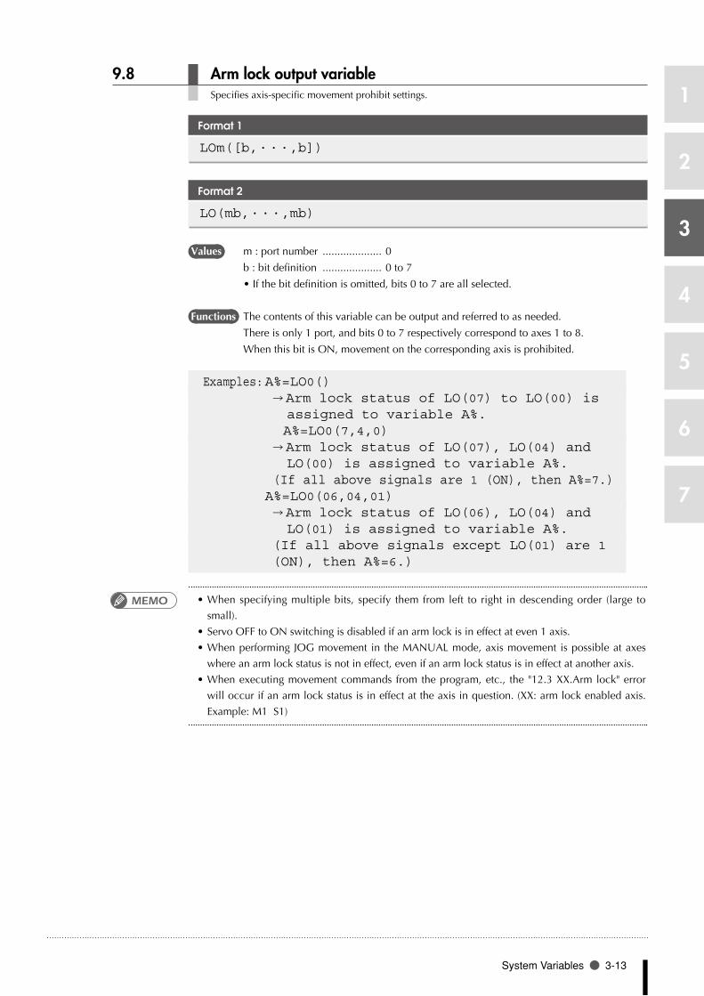
9.8 Arm lock output variable Specifies axis-specific movement prohibit settings.
Format 1
LOm([b,・・・,b])
Format 2
LO(mb,・・・,mb)
Values m : port number .................... 0
b : bit definition .................... 0 to 7
•Ifthebitdefinitionisomitted,bits0to7areallselected.
Functions The contents of this variable can be output and referred to as needed.
There is only 1 port, and bits 0 to 7 respectively correspond to axes 1 to 8.
When this bit is ON, movement on the corresponding axis is prohibited.
Examples: A%=LO0() → Arm lock status of LO(07) to LO(00) is assigned to variable A%. A%=LO0(7,4,0) → Arm lock status of LO(07), LO(04) and LO(00) is assigned to variable A%. (If all above signals are 1 (ON), then A%=7.) A%=LO0(06,04,01) → Arm lock status of LO(06), LO(04) and LO(01) is assigned to variable A%. (If all above signals except LO(01) are 1 (ON), then A%=6.)
•When specifying multiple bits, specify them from left to right in descending order (large to
small).
•ServoOFFtoONswitchingisdisabledifanarmlockisineffectateven1axis.
•WhenperformingJOGmovement in theMANUALmode,axismovement ispossibleataxes
where an arm lock status is not in effect, even if an arm lock status is in effect at another axis.
•Whenexecutingmovementcommandsfromtheprogram,etc., the"12.3XX.Armlock"error
will occur if an arm lock status is in effect at the axis in question. (XX: arm lock enabled axis.
Example: M1 S1)
MEMO

1
2
3
4
5
6
7
3-14 Chapter 3 Variables
9.9 Timer output variable This variable is used in the timer function of a sequence program.
Format 1
TOm([b,・・・,b])
Format 2
TO(mb,・・・,mb)
Values m : port number .................... 0
b : bit definition .................... 0 to 7
•Ifthebitdefinitionisomitted,bits0to7areallselected.
Functions The contents of this variable can be changed and referred to as needed.
Timer function can be used only in the sequence program. If this variable is output in a
normal program, it is an internal output.
For details regarding sequence program usage examples, refer to the timer usage examples given in
Chapter 7 "4.2 Input/output variables".
Examples: A%=TO0() → Status of TO(07) to TO(00) is assigned to variable A%. A%=TO0(7,4,0) → Status of TO(07), TO(04) and TO(00) is assigned to variable A%. (If all above signals are 1 (ON), then A%=7.) A%=TO(06,04,01) → Status of TO(06), TO(04) and TO(01) is assigned to variable A%. (If all above signals except TO(01) are 1 (ON), then A%=6.)
•When specifying multiple bits, specify them from left to right in descending order (large to
small).MEMO

1
2
3
4
5
6
7
System Variables 3-15
9.10 Serial input variable This variable is used to indicate the status of serial input signals.
Format 1
SIm([b,・・・,b])
Format 2
SI(mb,・・・,mb
Values m : port number .................... 0 to 7, 10 to 17, 20 to 27
b : bit definition .................... 0 to 7
•Ifthebitdefinitionisomitted,bits0to7areallselected.
Examples: A%=SI1() → Input status of ports SI(17) to SI(10) is assigned to variable A%. A%=SI5(7,4,0) → Input status of SI(57), SI(54) and SI(50) is assigned to variable A%. (If all above signals are 1(ON), then A%=7.) A%=SI(27,15,10) → Input status of SI(27), SI(15) and SI(10) is assigned to variable A%. (If all above signals except SI(10) are 1 (ON), then A%=6.) WAIT SI(21)=1 → Waits until SI(21) sets to 1 (ON).
•When specifying multiple bits, specify them from left to right in descending order (large to
small).
•A'0'isenteredifthereisnoactualserialboard.
MEMO

1
2
3
4
5
6
7
3-16 Chapter 3 Variables
9.11 Serial output variable This variable is used to define the serial output signals and indicate the output status.
Format 1
SOm([b,・・・,b])
Format 2
SO(mb,・・・,mb)
Values m : port number .................... 0 to 7, 10 to 17, 20 to 27
b : bit definition .................... 0 to 7
•Ifthebitdefinitionisomitted,bits0to7areallselected.
Examples: A%=SO2() → Output status of SO(27) to SO(20) is assigned to variable A%. A%=SO5(7,4,0) → Output status of SO(57), SO(54) and SO(50) is assigned to variable A%. (If all above signals are 1(ON), then A%=7.) A%=SO(37,25,20) → Output status of SO(37), SO(25) and SO(20) is assigned to variable A%. (If all above signals except SO(25) are 1 (ON), then A%=5.) SO3()=B% →Changes to a status in which the DO(37) to DO(30) output can be indicated by B%. For example, if B% is "123": If a binary number is used, "123" will become "01111011", DO(37) and DO(32) will become "0", and the other bits will become "1". SO4(5,4,0)=&B101 → DO(45) and DO(40) become "1", and DO(44) becomes "0".
•When specifying multiple bits, specify them from left to right in descending order (large to
small).
•Externaloutputisunavailableiftheserialportdoesnotactuallyexist.
MEMO

1
2
3
4
5
6
7
System Variables 3-17
9.12 Serial word input This variable indicates the status of the serial input word information.
Format
SIW(m)
Values m : Port No. 2 to 15
The acquisition range is 0 (&H0000) to 65535 (&HFFFF).
Examples: A%=SIW(2) → The input state from SIW (2) is assigned to variable A%. A%=SIW(15) → The input state from SIW (15) is assigned to variable A%.
•The information is handled as unsigned word data.
•'0'isinputiftheserialportdoesnotactuallyexist.
9.13 Serial double word input This variable indicates the state of the serial input word information as a double word.
Format
SID(m)
Values m : Port No. 2, 4, 6, 8, 10, 12, 14
The acquisition range is -1073741824 (&HC0000000) to 1073741823 (&H3FFFFFFF).
Examples: A%=SID(2) → The input state from SIW (2) , SIW (3) is assigned to variable A%. A%=SID(14) →The input state from SIW (14), SIW (15) is assigned to variable A%.
•The information is handled as signed double word data.
•'0'isinputiftheserialportdoesnotactuallyexist.
•An error will occur if the value is not within the acquisition range (&H80000000 to
&HBFFFFFFF, &H40000000 to &H7FFFFFFF.)
•Thelowerportnumberdataisplacedattheloweraddress.
For example, if SIW(2) =&H2345,SIW(3) =&H0001, then SID(2) =&H000123245.
n NOTE
The ser ia l word input •function is available from sof tware vers ion 8 .08 onwards.
MEMO
n NOTE
The serial double word •input function is available from software version 8.08 onwards.
MEMO

1
2
3
4
5
6
7
3-18 Chapter 3 Variables
9.14 Serial word output Outputs to the serial output word information or indicates the output status.
Format
SOW(m)
Values m : Port No. 2 to 15
The output range is 0 (&H0000) to 65535 (&HFFFF).
Note that if a negative value is output, the low-order word information will be output
after being converted to hexadecimal.
Examples: A%=SOW(2) → The output status from SOW (2) is assigned to variable A%. SOW(15)=A% → The contents of variable A% are assigned in SOW (15). If the variable A% value exceeds the output range, the low-order word information will be assigned. SOW(15)=-255 → The contents of -255 (&HFFFFFF01) are assigned to SOW (15). -255 is a negative value, so the low-order word information (&HFF01) will be assigned.
•The information is handled as unsigned word data.
•Ifaserialboarddoesnotactuallyexist,theinformationisnotoutputexternally.
•Ifavalueexceedingtheoutputrangeisassigned,thelow-order2-byteinformationisoutput.
9.15 Serial double word output Output the status of serial output word information in a double word, or indicates the output status.
Format
SOD(m)
Values m : Port No. 2, 4, 6, 8, 10, 12, 14
The output range is -1073741824 (&HC0000000) to 1073741823 (&H3FFFFFFF).
Examples: A%=SOD(2) → The input status from SOW (2) is assigned to variable A%. SOD(14)=A% →The contents of variable A% are assigned in SOD (14).
•Theinformationishandledassigneddoubleworddata.
•Ifaserialboarddoesnotactuallyexist,theinformationisnotoutputexternally.
•Anerrorwilloccurifthevalueisnotwithintheoutputrange(&H80000000to&HBFFFFFFF,
&H40000000 to &H7FFFFFFF.)
•Thelowerportnumberdataisplacedattheloweraddress.
For example, if SOW(2) =&H2345,SOW(3) =&H0001, then SOD(2) =&H000123245.
n NOTE
The serial word output •function is available from sof tware vers ion 8 .08 onwards.
MEMO
n NOTE
The serial double word •o u t p u t f u n c t i o n i s available from software version 8.08 onwards.

1
2
3
4
5
6
7
Bit Settings 3-19
10 Bit Settings
Bits can be specified for input/output variables by any of the following methods.
1. Single bit
To specify only 1 of the bits, the target port number and bit number are specified in parentheses.
The port number may also be specified outside the parentheses.
Programming example: DOm(b)DOm(b)
Example: DO(25) Specifies bit 5 of port 2. DO2(5)
2. Same-port multiple bits
To specify multiple bits at the same port, those bit numbers are specified in parentheses (separated
by commas) following the port number.
The port number may also be specified in parentheses.
Programming example: DOm(b,b,…,b) DO(mb,mb,…,mb)
Example: DO2(7,5,3) Specifies DO(27), DO(25), DO(23) DO(27,25,23)
3. Different-port multiple bits
To specify multiple bits at different ports, the port number and the 2-digit bit number must be
specified in parentheses and must be separated by commas.
Programming example: DO(mb,mb,…,mb)
Example: DO(37,25,20) Specifies DO(37), DO(25), DO(20).
4. All bits of 1 port
To specify all bits of a single port, use parentheses after the port number. Methods 2 and 3 shown
above can also be used.
Programming example: DOm()
Example: DO2() Specifies all the DO(27) to DO(20) bits →The same result can be obtained by the following: DO(27,26,25,24,23,22,21,20) or, DO2(7,6,5,4,3,2,1,0)

1
2
3
4
5
6
7
3-20 Chapter 3 Variables
11 Valid range of variables
Variable branching occurs as shown below.
11.1 Valid range of dynamic variables
Dynamic variables are divided into global variables and local variables, according to their
declaration position in the program. Global and local variables have different valid ranges.
Variable Type Explanation
Global variables Variables are declared outside of sub-procedures (outside of program areas enclosed by a SUB statement and END SUB statement). These variables are valid throughout the entire program.
Local variables Variables are declared within sub-procedures and are valid only in these sub-procedures.
11.2 Valid range of static variables
Static variable data is not cleared when a program reset occurs. Moreover, variable data can be
changed and referenced from any program.
The variable names are determined as shown below (they cannot be named as desired).
Variable type Variable name
Integer variable SGIn (n: 0 to 7)
Real variable SGRn (n: 0 to 7)
11.3 Valid range of dynamic array variables
Dynamic array variables are classified into global array variables and local array variables according
to their declaration position in the program.
Variable Type Explanation
Global variables Variables are declared outside of sub-procedures (outside of program areas enclosed by a SUB statement and END SUB statement). These variables are valid throughout the entire program.
Local variables Variables are declared within sub-procedures and are valid only in these sub-procedures.
•For details regarding arrays, refer to Chapter 3 "5 Array variables".
•Avariabledeclaredat theprogramlevelcanbe referenced fromasub-procedurewithout
being passed along as a dummy argument, by using the SHARED statement (for details, refer to
Chapter 8 "91 SHARED").
MEMO
1
2
3
4
5
6
7
Clearing variables 3-21
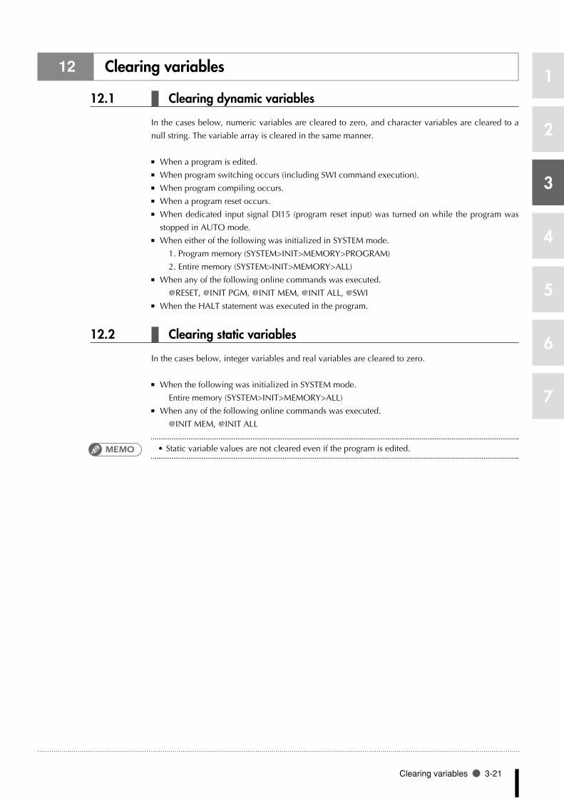
12 Clearing variables
12.1 Clearing dynamic variables
In the cases below, numeric variables are cleared to zero, and character variables are cleared to a
null string. The variable array is cleared in the same manner.
When a program is edited. ■
When program switching occurs (including SWI command execution). ■
When program compiling occurs. ■
When a program reset occurs. ■
When dedicated input signal DI15 (program reset input) was turned on while the program was ■
stopped in AUTO mode.
When either of the following was initialized in SYSTEM mode. ■
1. Program memory (SYSTEM>INIT>MEMORY>PROGRAM)
2. Entire memory (SYSTEM>INIT>MEMORY>ALL)
When any of the following online commands was executed. ■
@RESET, @INIT PGM, @INIT MEM, @INIT ALL, @SWI
When the HALT statement was executed in the program. ■
12.2 Clearing static variables
In the cases below, integer variables and real variables are cleared to zero.
When the following was initialized in SYSTEM mode. ■
Entire memory (SYSTEM>INIT>MEMORY>ALL)
When any of the following online commands was executed. ■
@INIT MEM, @INIT ALL
•Static variable values are not cleared even if the program is edited.MEMO


Chapter 4
Expressions and Operations
1 1 Arithmetic operations ..............................4-1
2 2 Character string operations ....................4-4
3 3 Point data format ......................................4-5
4 4 DI/DO conditional expressions ...............4-6


1
2
3
4
5
6
7
Arithmetic operations 4-1
1 Arithmetic operations
1.1 Arithmetic operators
Operators Usage Example Meaning
+ A+B Adds A to B
- A-B Subtracts B from A
* A*B Multiplies A by B
/ A/B Divides A by B
^ A^B Obtains the B exponent of A (exponent operation)
- -A Reverses the sign of A
MOD A MOD B Obtains the remainder A divided by B
When a "remainder" (MOD) operation involves real numbers, the decimal value is rounded off to
the nearest whole number which is then converted to an integer before the calculation is executed.
The result represents the remainder of an integer division operation.
Examples: A=15 MOD 2 → A=1(15/2=7....1) A=17.34 MOD 5.98 → A=2(17/5=3....2)
1.2 Relational operators
Relational operators are used to compare 2 values. If the result is "true", a "-1" is obtained. If it is
"false", a "0" is obtained.
Operators Usage Example Meaning
= A=B "-1" if A and B are equal, "0" if not.
<>, >< A<>B "-1" if A and B are unequal, "0" if not.
< A<B "-1" if A is smaller than B, "0" if not.
> A>B "-1" if A is larger than B, "0" if not.
<=, =< A<=B "-1" if A is equal to or smaller than B, "0" if not.
>=, => A>=B "-1" if A is equal to or larger than B, "0" if not.
Examples: A=10>5 → Since 10 > 5 is "true", A = -1.
•When using equivalence relational operators with real variables and real arrays, the desired
result may not be obtained due to the round-off error.
Examples: .............................A=2
B=SQR(A!)
IF A!=B!*B! THEN...
→ In this case, A! will be unequal to B!*B!.
MEMO

4-2 Chapter 4 Expressions and Operations
1
2
3
4
5
6
7
1.3 Logic operations
Logic operators are used to manipulate 1 or 2 values bit by bit. For example, the status of an I/O
port can be manipulated.
Depending on the logic operation performed, the results generated are either 0 or 1. ■
Logic operations with real numbers convert the values into integers before they are executed. ■
Operators Functions Meaning
NOT, ~ Logical NOT Reverses the bits.
AND, & Logical AND Becomes "1" when both bits are "1".
OR, | Logical OR Becomes "1" when either of the bits is "1".
XOR Exclusive OR Becomes "1" when both bits are different.
Examples: A%=NOT 13.05 → "-14" is assigned to A% (reversed after being rounded off to 13).
Bit 7 6 5 4 3 2 1 0
13 0 0 0 0 1 1 0 1
NOT 13=-14 1 1 1 1 0 0 1 0
Examples: A%=3 AND 10 → "2" is assigned to A%
Bit 7 6 5 4 3 2 1 0
3 0 0 0 0 0 0 1 1
10 0 0 0 0 1 0 1 0
3 AND 10 = 4 0 0 0 0 0 0 1 0
Examples: A%=3 OR 10 → "11" is assigned to A%
Bit 7 6 5 4 3 2 1 0
3 0 0 0 0 0 0 1 1
10 0 0 0 0 1 0 1 0
3 OR 10 = 11 0 0 0 0 1 0 1 1
Examples: A%=3 XOR 10 → "9" is assigned to A%
Bit 7 6 5 4 3 2 1 0
3 0 0 0 0 0 0 1 1
10 0 0 0 0 1 0 1 0
3 OR 10 = 11 0 0 0 0 1 0 0 1

1
2
3
4
5
6
7
Arithmetic operations 4-3
1.4 Priority of arithmetic operation
Operations are performed in the following order of priority. When two operations of equal priority
appear in the same statement, the operations are executed in order from left to right.
Priority Rank Arithmetic Operation
1 Expressions included in parentheses
2 Functions, variables
3 ^ (exponents)
4 Independent "+" and "-" signs (monominal operators)
5 * (multiplication), / (division)
6 MOD
7 + (addition), - (subtraction)
8 Relational operators
9 NOT, ~ (Logical NOT)
10 AND, & (logical AND)
11 OR, |, XOR (Logical OR, exclusive OR)
1.5 Data format conversion
Data format is converted in cases where two values of different formats are involved in the same
operation.
When a real number is assigned to an integer, decimal places are rounded off111
Examples: A%=125.67 → A%=126
When integers and real numbers are involved in the same operation, the result 21
becomes a real number1
Examples: A(0)=125 * 0.25 → A(0)=31.25
When an integer is divided by an integer, the result is an integer with the remainder 31
discarded1
Examples: A(0)=100/3 → A(0)=33

4-4 Chapter 4 Expressions and Operations
1
2
3
4
5
6
7
2 Character string operations
2.1 Character string connection
Character strings may be combined by using the "+" sign.
SAMPLE
A$="YAMAHA"B$="ROBOT"C$="LANGUAGE"D$="MOUNTER"E$=A$+" "+B$+" "+C$F$=A$+" "+D$PRINT E$PRINT F$
Results: YAMAHA ROBOT LANGUAGE YAMAHA MOUNTER
2.2 Character string comparison
Characters can be compared with the same relational operators as used for numeric values.
Character string comparison can be used to find out the contents of character strings, or to sort
character strings into alphabetical order.
In the case of character strings, the comparison is performed from the beginning of each string, ■
character by character.
If all characters match in both strings, they are considered to be equal. ■
Even if only one character in the string differs from its corresponding character in the other string, ■
then the string with the larger (higher) character code is treated as the larger string.
When the character string lengths differ, the longer of the character strings is judged to be the ■
greater value string.
All examples below are "true".
Examples: "AA"<"AB" "X&">"X#" "DESK"<"DESKS"

1
2
3
4
5
6
7
Point data format 4-5
3 Point data format
There are two types of point data formats: joint coordinate format and Cartesian coordinate format.
Point numbers are in the range of 0 to 9999.
Coordinate Format Data Format Explanation
Joint coordinate format
± nnnnnnn This is a decimal integer constant of 7 digits or less with a plus or minus sign, and can be specified from –6144000 to 6144000.Unit: [pulses]
Cartesian coordinate format
± nnn.nn to ± nnnnnnn This is a decimal fraction of a total of 7 digits including 2 or less decimal places.Unit: [mm] or [degrees]
When setting an extended hand system flag for SCARA robots, set either 1 or 2 at the end of the
data. If a value other than 1 or 2 is set, or if no value is designated, 0 will be set to indicate that no
hand system flag is set.
Hand System Data Value
RIGHTY (right-handed system) 1
LEFTY (left-handed system) 2
On the YK500TW model robot, the X-arm and Y-arm movement range is extended beyond 360
degrees (The movable range for both the X-arm and Y-arm is -225° to +225°).
Therefore, attempts to convert Cartesian coordinate data ("mm" units) to joint coordinate data (pulse
units) will result in multiple solutions, making the position impossible to determine.
In order to obtain the correct robot position and arm posture when converting to joint coordinates,
X-arm and Y-arm rotation information is added after the "mm" units point data's extended hand
system flag.
The Cartesian coordinate data ("mm" units) is then converted to joint coordinate data (pulse units)
according to the specified X-arm and Y-arm rotation information.
To set extended X-arm and Y-arm rotation information at the YK500TW model robot, a "-1", "0",
or "1" value must be specified after the hand system flag. Any other value, or no value, will be
processed as "0".
Arm rotation information Data Value
"mm" → pulse converted angle data x (*1) range: -180° < x <= 180° 0
"mm" → pulse converted angle data x (*1) range: 180° < x <= 540° 1
"mm" → pulse converted angle data x (*1) range: -540° < x <= -180° -1
*1: The joint-coordinates-converted pulse data represents each arm's distance (converted to angular
data) from its mechanical origin point.
n NOTE
F o r c o n t r o l l e r s w i t h •software versions of 8.28 and ear l ier, the point n u m b e r s w h i c h c a n be specif ied by point variables are 0 to 4000.
The XYZRAB data format •is used for both the joint coordinate format and the Cartesian coordinate format.
P lus (+) s igns can be •omitted.
Hand system flags are •o n l y a v a i l a b l e f r o m sof tware vers ion 8 .08 onwards.
X-arm and Y-arm rotation •i n f o r m a t i o n i s o n l y avai lable in sof tware Ver.10.66 onwards.
X-arm and Y-arm rotation •information is not available o n a n y r o b o t m o d e l except the YK500TW.

4-6 Chapter 4 Expressions and Operations
1
2
3
4
5
6
7
4 DI/DO conditional expressions
DI/DO conditional expressions may be used to set conditions for WAIT statements and STOPON
options in MOVE statements.
Numeric constants, variables and arithmetic operators that may be used with DI/DO conditional
expressions are shown below.
Constant •
Decimal integer constant, binary integer constant, hexadecimal integer constant
Variables •
Global integer type, global real number type, input/output type
Operators •
Relational operators, logic operators
Operation priority •
1. Relational operators
2. NOT, ~
3. AND, &
4. OR, |, XOR
Examples: WAIT DI(31)=1 OR DI(34)=1 → The program waits until either DI31 or DI34 turns ON.

Chapter 5
Multiple Robot Control
1 1 Overview ...................................................5-1
2 2 Command list for each group .................5-2


1
2
3
4
5
6
7
Overview 5-1
1 Overview
The YAMAHA robot RCX controller can be used to control multiple robots.
The multitask function also enables multiple robots to move asynchronously.
To use this function, settings for two robots or settings for auxiliary axes must be made in the system
prior to shipment.
A robot axis is classified into one of the groups below.
■ Main group (6 axes)
Main group (6 axes) + sub-group (2 axes) (when using the YC-LINK option) ■
Main group (4 axes) + sub-group (4 axes) (when using the YC-LINK option) ■
Main group (2 axes) + sub-group (2 axes) ■
Main group (3 axes) + sub-group (3 axes) ■
(This setting is possible only when using the YC-LINK option and a compatible software version:
Ver.8.69 or newer for RCX14x, and Ver.9.16 or newer for RCX22x.)
A main group is composed of one main robot and main auxiliary axes, and a sub group is composed
of one sub robot and sub auxiliary axes.
When using one robot without auxiliary axis, settings are made only for the main group robot.
When no settings have been made for main auxiliary axes and sub auxiliary axes, the main group is
composed only of the one main robot, and the sub group is composed only of the one sub robot.
Main group Main robot
(Number of axes: 1 to 4)
1. For main group only
2. For main group & sub-group
3. For 1 robot with no additional axes used
4. When no main additional axes & sub additional axes are set
Main auxiliary axis
(Number of axes: 1 to 4)
Main group Main robot
(Number of axes: 1 or 2)
Main auxiliary axis
(Number of axes: 1 or 2)
sub-group Sub robot
(Number of axes: 1 or 2)
Sub auxiliary axis
(Number of axes: 1 or 2)
Main group Main robot
(Number of axes: 1 to 4)
Main auxiliary axis
(None)
Main group Main robot
(Number of axes: 1 or 2)
Main auxiliary axis
(None)
sub-group Sub robot
(Number of axes: 1 or 2)
Sub auxiliary axis
(None)
Axes configuration
33501-R7-00

1
2
3
4
5
6
7
5-2 Chapter 5 Multiple Robot Control
2 Command list for each group
The special commands and functions for robot movement and coordinate control are shown below.
Operator Main group Sub group
Robot movement DRIVEMOVEPMOVEWAIT ARM
DRIVEIMOVEISERVO
DRIVE2MOVE2PMOVE2WAIT ARM2
DRIVEI2MOVEI2SERVO2
Coordinate control CHANGELEFTYSHIFT
HANDRIGHTY
CHANGE2LEFTY2SHIFT2
HAND2RIGHTY2
Status change ACCELASPEEDDECELOUTPOSTOLE
ARCHAXWEIGHTORGORDSPEEDWEIGHT
ACCEL2ASPEED2DECEL2OUTPOS2TOLE2
ARCH2AXWEIGHT2ORGORD2SPEED2WEIGHT2
Point operation JTOXYXYTOJ
WHERE JTOXY2WXTOJ2
WHERE2
Parameter reference ACCELAXWEIGHTORGORDTOLE
ARCHDECELOUTPOSWEIGHT
ACCEL2AXWEIGHT2ORGORD2TOLE2
ARCH2DECEL2OUTPOS2WEIGHT2
Status reference ABSRPOSARMTYPE
ARMCNDMCHREF
ABSRPOS2ARMTYPE2
ARMCND2MCHREF2
PATH control PATHPATH SET
PATH ENDPATH START
Torque control DRIVE (with torque limit setting option)
DRIVE2 (with torque limit setting option)
TORQUETRQTIME
TRQSTSCURTRQ
TORQUE2TRQTIME2
TRQSTS2CURTRQ2
MOVE, MOVEI commands are used at main robot operations, and MOVE2, MOVEI2 commands ■
are used at sub-robot operations.
An axis specified as an auxiliary axis cannot be moved with the MOVE (MOVE2), MOVEI ■
(MOVEI2) and PMOVE (PMOVE2) commands. Use the DRIVE (DRIVE2) or DRIVEI (DRIVEI2)
command to move it.
When specifying all axes with the SERVO or SERVO2 command, the servos of all axes in the ■
main group and sub group can be switched ON or OFF.
•The restrictions shown below apply to the following software versions: RCX14x…version prior
to Ver.8.64; RCX22x…versions prior to Ver.9.11.
•TheMOVEstatement'slinearandcircularinterpolationsareonlypossibleatTask1(maintask)
and by direct command.
•TheMOVE2statementcanbeusedonly forPTPcontrol. Itcannotbeused for linearand
circular interpolations.
MEMO

Chapter 6
Multi-tasking
1 1 Outline .......................................................6-1
2 2 Task definition ...........................................6-1
3 3 Task status and transition .........................6-2
4 4 Multi-task program example ..................6-8
5 5 Sharing the data .......................................6-8
6 6 Cautionary Items ......................................6-9


1
2
3
4
5
6
7
Outline 6-1
1 Outline
The multi-task function performs multiple processing simultaneously in a parallel manner, and can
be used to create programs of higher complexity. Before using the multi-tasking function, read this
section thoroughly and make sure that you fully understand its contents.
Multi-tasking allows executing two or more tasks in parallel. However, this does not mean that
multiple tasks are executed simultaneously because the controller has only one CPU to execute the
tasks. In multi-tasking, the CPU time is shared among multiple tasks by assigning a priority to each
task so that they can be executed efficiently.
A maximum of 8 tasks (task 1 to task 8) can be executed in one program. ■
Tasks can be prioritized and executed in their ■ priority order (higher priority tasks are executed first).
The priority level of task 1 is fixed at 32, while the priority of task 2 to task 8 can be set to any ■
level between 17 and 47.
Smaller values have higher priority, and larger values have lower priority ■
(High priority: 17 ⇔ 47: low priority).
•In RCX14x software version prior to Ver.8.64, and in RCX22x software versions prior to Ver.9.11,
the MOVE statement's linear and circular interpolations are possible only at Task 1 (main task).
2 Task definition
A task is a set of instructions within a program which are executed as a single sequence. As explained below, a task is defined by assigning a label to it.
1. Assign a label to the first line of the command block which is to be defined as a task.
2. At the Task 1 (main task) START statement, specify the label which was assigned at step 1
above. Task Nos. are then assigned, and the program starts.
The task definition may call for 2 to 8 subtasks. Task 1 (main task) is automatically defined.
•Although all tasks are written within a single program, parallel processing occurs at each of the tasks.
SAMPLE
’MAIN TASK(TASK1)START *IOTASK,T2 ・・・・・・・・・・・・・・・・・ *IOTASK is started as Task 2*ST1:MOVE P,P1,P0 IF DI(20)= 1 THEN HALT ENDIFGOTO *STHALT’SUB TASK(TASK2)*IOTASK: ・・・・・・・・・・・・・・・・・・・・・・・・・・・・・ Task 2 begins from here IF DI(21)=1 THEN DO(30)=1 ELSE DO(30)=0 ENDIFGOTO *IOTASK ・・・・・・・・・・・・・・・・・・・・・・・ Task 2 processing ends hereEXIT TASK
MEMO
MEMO

1
2
3
4
5
6
7
6-2 Chapter 6 Multi-tasking
3 Task status and transition
There are 6 types of task status.
11 STOP status
A task is present but the task processing is stopped.
21 RUN status
A task is present and the task processing is being executed by the CPU.
31 READY status
A task is present and ready to be allocated to the CPU for task processing.
41 WAIT status
A task is present and waiting for an event to begin the task processing.
51 SUSPEND status
A task is present but suspended while waiting to begin the task processing.
61 NON EXISTEN status
No tasks exist in the program. (The START command is used to perform a call).
Task state transition
Delete Call
NON EXISTEN
Resume
Start
Suspend
Wait conditionCancel waiting
StopStop Stop Stop
CPU assignment
Wait for CPU assignment
STOP
RUNSUSPEND READY WAIT
33601-R7-00
3.1 Starting tasks
When the program is being executed in the AUTO mode, Task 1 (main task) is automatically
selected and placed in a RUN status when the program begins. Therefore, the delete, forced wait,
forced end commands, etc., cannot be executed for Task 1.
Other tasks (2 to 8 subtasks) will not be called simply by executing the program. The START
command must be used at Task 1 in order to call, start, and place these tasks in a READY status.
•The RESTART, SUSPEND, EXIT TASK, and CUT commands cannot be executed at Task 1.MEMO

1
2
3
4
5
6
7
Task status and transition 6-3
3.2 Task scheduling
Task scheduling determines the priority to be used in allocating tasks in the READY(execution
enabled) status to the CPU and executing them.
When there are two or more tasks which are put in the READY status, ready queues for CPU
allocation are used to determine the priority for executing the tasks. One of these READY status
tasks is then selected and executed (RUN status).
Only tasks with the same priority ranking are assigned to a given ready queue. Therefore, where
several tasks with differing priority rankings exist, a corresponding number of ready queues are
created. Tasks within a given ready queue are handled on a first come first serve (FCFS) basis. The
task where a READY status is first established has priority. The smaller the number, the higher the
task priority level.
Task 1 Task 3
Task 1
Task 4
Task 5
Task 2
Ready queue 1
Ready queue 2
Ready queue 3
Order in which tasks are put in READY status.
The head of the task with the highest priority is put in RUN status.High
Low
32
33
34
Priority level
Task scheduling
33602-R7-00
A RUN status task will be moved to the end of the ready queue if placed in a READY status by any
of the following causes:
1) A WAIT status command was executed.
2) The CPU occupation time exceeds a specified time.
3) A task with a higher priority level is put in READY status.
Task 1
RUN status READY status
Moves to the end of the ready queue, and Task 3 is executed.
Task 3 Task 4
Execution sequence
1
Task 1 Task 3 Task 4 Task 1
2
Moves to the end of the ready queue, and Task 4 is executed.
Task 3 Task 4 Task 1 Task 3
3
Ready queue
33603-R7-00
n NOTE
When the prescribed CPU •occupation time elapses, the active command is ended, and processing moves to the next task. However, if there are no other tasks of the same or higher priority (same or higher ready queue), the same task wi l l be executed again.

1
2
3
4
5
6
7
6-4 Chapter 6 Multi-tasking
3.3 Condition wait in task
A task is put in the WAIT status (waiting for an event) when a command causing a wait status is
executed for that task. At this time, the transition to READY status does not take place until the wait
condition is canceled.
When a command causing a wait status is executed, the following transition happens111
Task for which a command causing a wait status is executed ■ → WAIT status
Task at the head of the ready queue with higher priority ■ → RUN status
•For example, when a MOVE statement (a command that establishes a WAIT status)
is executed, the CPU sends a "MOVE" instruction to the driver, and then waits for a
"MOVE COMPLETED" reply from the driver. This is a "waiting for an event" status.
In this case, a WAIT status is established at the task which executed the MOVE command, and that
task is moved to the end of the ready queue. A RUN status is then established at the next task.
21 When an event waited by the task in the WAIT status occurs, the following status
transition takes place by task scheduling1
Task in the WAIT status for which the awaited event occurred ■ → READY status
However, if the task put in the READY status was at the head of the ready queue with the
highest priority, the following transition takes place.
1) Task that is currently in RUN status → READY status
2) Task at the head of the ready queue with higher priority → RUN status
•In the above MOVE statement example, the task is moved to the end of the ready queue. Then,
when a "MOVE COMPLETED" reply is received, this task is placed in READY status.
Tasks are put in WAIT status by the following commands.
Event Command
Wait for axis movement to complete
Axis movement command
MOVE DRIVE PMOVEWAIT ARM
MOVEIDRIVEIPMOVE2WAIT ARM2
MOVE2DRIVE2SERVO
MOVEI2DRIVEI2SERVO2
Parameter command
ACCELAXWEIGHTOUTPOSORGORD
ACCEL2AXWEIGHT2OUTPOS2ORGORD2
ARCHDECELTOLEWEIGHT
ARCH2DECEL2TOLE2WEIGHT2
Robot status change command
CHANGELEFTYASPEED
CHANGE2LEFTY2ASPEED2
SHIFTRIGHTYSPEED
SHIFT2RIGHTY2SPEED2
Wait for time to elapse DELAY, SET (Time should be specified.), WAIT (Time should be specified.)
Wait for condition to be met WAIT
Wait for data to send or to be received SEND
Wait for print buffer to become empty PRINT
Wait for key input INPUT
•The tasks are not put in WAIT status if the event has been established before the above
commands are executed.
MEMO
n NOTE
I f mult iple tasks are in •WAIT status awaiting the same condition event, or different condition events occur simultaneously, all tasks for which the waited events occur are put in READY status.
MEMO
MEMO

1
2
3
4
5
6
7
Task status and transition 6-5
3.4 Suspending tasks (SUSPEND)
The SUSPEND command temporarily stops tasks other than task 1 and places them in SUSPEND
status. The SUSPEND command cannot be used for task 1.
When the SUSPEND command is executed, the status transition takes place as follows.
Task that executed the SUSPEND command ■ → RUN status
Specified task ■ → SUSPEND status
Suspending tasks (SUSPEND)
Task 1 Task 2 Task 1
Task 2RUN READY RUN
SUSPEND
SUSPEND
Task 3
READY
Task 3
READY
The task is placed in a SUSPEND status, and is removed from the ready queue.
33604-R7-00
3.5 Restarting tasks (RESTART)
Tasks in the SUSPEND status can be restarted with the RESTART command. However, the RESTART
command cannot be used for task 1.
When the RESTART command is executed, the status transition takes place as follows.
Task for which the RESTART command was executed ■ → RUN status
Specified task ■ → READY status
Restarting tasks (RESTART)
Task 1
Task 2
Task 1 Task 3
RUN
SUSPEND
RUN READY
RESTART
Task 2
READY
Task 3
READY
The task is placed in a READY status, and is assigned to a ready queue.
33605-R7-00

1
2
3
4
5
6
7
6-6 Chapter 6 Multi-tasking
3.6 Deleting tasks
Task self-delete (EXIT TASK)
Tasks can delete themselves by using the EXIT TASK command and set to the NON EXISTEN (no
task registration) status. The EXIT TASK command cannot be used for task 1.
When the EXIT TASK command is executed, the status transition takes place as follows.
Task that executed the EXIT TASK command ■ → NON EXISTEN status
Task at the head of the ready queue with higher priority ■ → RUN status
Task self-delete (EXIT TASK)
Task 2 Task 3
Task 2
Task 3
RUN READY
NOT EXISTEN
RUN
EXIT TASK
Task 4
READY
Task 4
READY
The task is placed in a NOT EXISTEN status, and is removed from a ready queue.
33606-R7-00
Other-task delete (CUT)
A task can also be deleted and put in the NON EXISTEN (no task registration) status by the other
tasks using the CUT command. The CUT command cannot be used for task 1.
When the CUT command is executed, the status transition takes place as follows.
Task that executed the CUT command ■ → RUN
Specified task ■ → NON EXISTEN
Other-task delete (CUT)
Task 2 Task 3 Task 2
Task 3RUN READY
Task 4
READY
Task 4
READY RUN
NOT EXISTEN
CUT
The task is placed in a NOT EXISTEN status, and is removed from the ready queue.
33607-R7-00
•If a SUSPEND command is executed for a WAIT-status task, the commands being executed by
that task are ended.
•NoneofthesecommandscanbeexecutedforTask1.
MEMO

1
2
3
4
5
6
7
Task status and transition 6-7
3.7 Stopping tasks
All tasks stop if any of the following cases occurs.
HALT command is executed1 11 (stop & reset)
The program is reset and all tasks other than task 1 are put in the NON EXISTEN status. Task 1
is put in the STOP status.
HOLD command is executed1 21 (temporary stop)
All tasks are put in the STOP status. When the program is restarted, the tasks in the STOP status
set to the READY or SUSPEND status.
STOP key on the programming box is pressed or the interlock signal is cut off131
Just as in the case where the HOLD command is executed, all tasks are put in the STOP status.
When the program is restarted, the tasks in the STOP status set to the READY status (or, the task
is placed in a SUSPEND status after being placed in a READY status).
When the emergency stop switch on the programming box is pressed or the 41
emergency stop signal is cut off1
All tasks are put in STOP status. At this point, the power to the robot is shut off and the servo
sets to the non-hold state.
After the canceling emergency stop, when the program is restarted, the tasks in STOP status are
set to the READY or SUSPEND status. However, a servo ON is required in order to restart the
robot power supply.
•When the program is restarted without being reset after the tasks have been stopped by a cause
other than 1., then each task is processed from the status in which the task stopped. This holds
true when the power to the controller is turned off and then turned on.
MEMO

1
2
3
4
5
6
7
6-8 Chapter 6 Multi-tasking
4 Multi-task program example
Tasks are executed in their scheduled order. An example of a multi-task program is shown below.
SAMPLE
’TASK1START *ST2,T2START *ST3,T3*ST1: DO(20) = 1 WAIT MO(20) = 1 MOVE P,P1,P2,Z=0 IF MO(21)=1 THEN *FINGOTO *ST1 *FIN:CUT T2HALT’TASK2*ST2: ・・・・・・・・・・・・・・・・・・・・・・・・・・・・・ Task 2 begins here. IF DI(20) = 1 MO(20) = 1 DELAY 100 ELSE MO(20) = 0 ENDIFGOTO *ST2EXIT TASK ・・・・・・・・・・・・・・・・・・・・・・・・・・・・ Ends here.’TASK3 ・・・・・・・・・・・・・・・・・・・・・・・・・・・・・ Task 3 begins here.*ST3: IF DI(21) = 0 THEN *ST3 IF DI(30) = 0 THEN *ST3 IF DI(33) = 0 THEN *ST3 MO(21) = 1EXIT TASK ・・・・・・・・・・・・・・・・・・・・・・・・・・・・ Ends here.
5 Sharing the data
Point data, shift coordinate definition data, hand definition data, pallet definition data, all global
variables and other variables are shared between all tasks.
Execution of each task can be controlled while using the same variables and data shared with the
other tasks.
•In this case, however, use sufficient caution when rewriting the variable and data because
improper changes may cause trouble in the task processing.MEMO

1
2
3
4
5
6
7
Cautionary Items 6-9
6 Cautionary Items
A silence stop may occur if subtasks are continuously started (START command) and ended (EXIT
TASK command) by a main task in an alternating manner.
This occurs for the following reason: if the main task and subtask priority levels are the same, a task
transition to the main task occurs during subtask END processing, and an illegal task status then
occurs when the main task attempts to start a subtask.
Therefore, in order to properly execute the program, the subtask priority level must be set higher
than that of the main task. This prevents a task transition condition from occurring during execution
of the EXIT TASK command.
In the sample program shown below, the priority level of task 1 (main task) is set as 32, and the
priority level of task 2 is set as 31 (the lower the value, the higher the priority).
SAMPLE
FLAG1 = 0*MAIN_TASK: IF FLAG1=0 THEN FLAG1 = 1 START *TASK2,T2,31 ・・・・・・ Task 2 (*TASK2) is started at the priority level of 31. ENDIFGOTO *MAIN_TASK'==============' TASK2'==============*TASK2: DRIVE(1,P1) WAIT ARM(1) DRIVE(1,P2) WAIT ARM(1) FLAG1 = 0EXIT TASKHALT


Chapter 7
Sequence function
1 1 Sequence function ...................................7-1
2 2 Creating a sequence program ...............7-1
3 3 Executing a sequence program .............7-4
4 4 Creating a sequence program ...............7-5


Sequence function 7-1
1
2
3
4
5
6
7
1 Sequence function
Besides normal robot programs, this RCX controller can execute high-speed processing programs
(sequence programs) in response to the robot input/output (DI, DO, MO, LO TO, SI, SO) signals.
This means that when a sequence program is running, it is running simultaneously with the robot
program (2 programs are running).
When the dedicated "DI10: sequence control input" is ON, the sequence program runs according to
its own cycle in the AUTO or MANUAL mode, regardless of robot program starts and stops.
The sequence program starts running as soon as the controller is turned on (normally, the MANUAL
mode), so it can be used to monitor the status of sensors, push button switches, solenoid valves, etc.
The sequence program can be written in the same robot language used for robot programs. This
eliminates the need to learn a new language and making it easier to program.
General-purpose outputs are not reset while the sequence function is running, even if a program
reset is executed. However, a setting can be specified which allows these outputs to be reset at
the sequence program compiling operation. For details regarding settings required to execute a
sequence program, see section "3 Executing Sequence Programs".
2 Creating a sequence program
2.1 Programming method
The following explains how to create a sequence program in order to make use of the sequence
function.
First, enter "PROGRAM" mode and create a file with the file name "SEQUENCE". The controller
automatically recognizes that a file with this name is a sequence program.
PROGRAM>DIR <TEST10 >
No. Name Line Byte RW/RO 1 TEST10 12 145 RW 2 LOCATE20 25 320 RW
Enter program name >SEQUENCE
Naming a sequence program file
34701-R7-00
n NOTE
The "DO12: Sequence •p r o g r a m r u n n i n g " dedicated signal output occurs while a sequence p r o g r a m i s b e i n g executed.

1
2
3
4
5
6
7
7-2 Chapter 7 Sequence function
Next, input a program. This is no different from the standard robot program creation method.
Commands which can be input are explained later in this manual.
PROGRAM>EDIT <SEQUENCE> 1 2 3 1 DO(20)=DI(21) AND DI(22) 2 MO(30)=DO(23) OR DI(22) 3 MO(31)=~MO(30) 4 DO(21)=(DI(36) OR DI(25))AND DI(2 5 DO(30)=MO(30) OR DI(27)
SELECT COPY CUT PASTE BS
Creating a sequence program
34702-R7-00
2.2 Compiling
After editing the program, it must be compiled as a sequence program. Compiling is performed in
the same way as for robot programs. Press the F5 key on the highest-level screen in "PROGRAM"
mode.
PROGRAM>EDIT <SEQUENCE> 1 2 3 1 DO(20)=DI(21) AND DI(22) 2 MO(30)=DO(23) OR DI(22) 3 MO(31)=~MO(30) 4 DO(21)=(DI(36) OR DI(25))AND DI(2 5 DO(30)=MO(30) OR DI(27)
SELECT DIR COMPILE
Sequence program
34703-R7-00
A check message appears asking if you want to compile the sequence program. Press the F4 key
to compile the program. To cancel this compiling, press the F5 key. The display changes to the
compiling screen for normal robot programs.
Press the F4 key to compile the sequence program.
Compile the sequence program before compiling the main program.
PROGRAM>COMPILE <SEQUENCE> 1 2 3 1 DO(20)=DI(21) AND DI(22) 2 MO(30)=DO(23) OR DI(22) 3 MO(31)=~MO(30) 4 DO(21)=(DI(36) OR DI(25))AND DI(2 5 DO(30)=MO(30) OR DI(27)
Compile for SEQUENCE OK?YES NO
Compiling the sequence program
34704-R7-00

Creating a sequence program 7-3
1
2
3
4
5
6
7
If there is a syntax error in the program, an error message appears and the program will be listed
from the line with the error When the compiling ends without any error, the program will be listed
from its first line.
PROGRAM <SEQUENCE> 5.1:Syntax error 2 3 3 MO(31)=~MO(30)’AB 4 DO(21)=MO(36) OR DI(27) 5 DO(30)=MO(30) OR DI(27) 6 DO(25)=DI(26) AND DO(32) 7 DO(30)=MO(30) OR DI(27)
SELECT DIR COMPILE
Compiling error
34705-R7-00
•The sequence execution program is erased and the letter "s" disappears in the following cases.
In these cases the sequence function cannot be used in "UTILITY" mode.
1. When the sequence program was erased
2. When the sequence program was edited
3. When normal robot program compiling was performed for the sequence program
(The same processing occurs even if the mode is changed to AUTO while in the SEQUENCE
program is selected.)
4. Program data was initialized.
5. A "9.39: Sequence object destroyed.
When you display the directory after the compiling the sequence program, a letter "s" appears
to the left of the program name "SEQUENCE". This means that the sequence program has been
compiled successfully and is ready for use.
PROGRAM>DIR <TEST10 >
No. Name Line Byte RW/RO 1 TEST10 12 145 RW 2 LOCATE20 25 320 RW 3 sSEQUENCE 8 141 RW
NEW INFO
Sequence execution program after compiling
34706-R7-00
MEMO

1
2
3
4
5
6
7
7-4 Chapter 7 Sequence function
3 Executing a sequence program
The following conditions must be satisfied to execute a sequence program. If any of these conditions
is not met, the sequence program cannot be executed.
1. The sequence execution program has been created by compiling.
2. The sequence function is enabled in "UTILITY" mode.
(For details regarding the UTILITY mode, refer to the controller manual.)
3. The external sequence control input (DI10) contact is closed.
4. The current operation mode is "MANUAL" or "AUTO".
When all of the above conditions are met, the sequence program can now be executed. While the
program is running, the letter "s" will appear at the left end of the second line of the screen.
MANUAL 50% [MG][SOHOJ]sCurrent position M1= 0 M2= 0 *M3= 0*M4= 0
POINT PALLET VEL+ VELー
Sequence program execution in progress
34707-R7-00
For details regarding the UTILITY mode setting procedure, refer to the controller manual.
3.1 Sequence program STEP execution
The sequence program may be executed line by line while checking one command line at a time.
To do this, press the F5 key on the compile screen. Sequence program compiling is canceled and
the normal robot compile screen then appears.
Press the F4 key to compile and create a normal execution program. Then, execute this program
with the STEP statement in "AUTO" mode to check the operation.PROGRAM>COMPILE <SEQUENCE> 1 2 3 1 DO(20)=DI(21) AND DI(22) 2 MO(30)=DO(23) OR DI(22) 3 MO(31)=~MO(30) 4 DO(21)=(DI(36) OR DI(25))AND DI(2 5 DO(30)=MO(30) OR DI(27)
Compile for SEQUENCE OK?YES NO
PROGRAM>COMPILE <SEQUENCE> 1 2 3 1 DO(20)=DI(21) AND DI(22) 2 MO(30)=DO(23) OR DI(22) 3 MO(31)=~MO(30) 4 DO(21)=(DI(36) OR DI(25))AND DI(2 5 DO(30)=MO(30) OR DI(27)
Compile program OK? YES NO
Sequence program STEP execution
Press the F5 key.
Press the F4 key.
32708-R7-00

Creating a sequence program 7-5
1
2
3
4
5
6
7
4 Creating a sequence program
When creating a sequence program, you may use only assignment statements comprised of input/
output variables and logical operators. An error will occur during compiling if any statement other
than assignment statements is used in the program, and the compiling cannot be completed.
4.1 Assignment statements
Format
<output variable> =<expression> <internal auxiliary output variable> <arm lock output variable> <timer output variable>
Values <expression> ......................... Any one of the following can be used.
•Parallelinput/outputvariables
•Internalauxiliaryoutputvariables
•Armlockoutputvariables
•Timeroutputvariables
•Serialinput/outputvariable
•Thelogicoperationexpressionshownabove
4.2 Input/output variables
Each variable must be specified in a 1-bit format
・Correct examples DO(35) MO(24) DI(16)・Incorrect examples DO(37, 24) DI3(4) MO3()
Parallel input variables ●
Format
DI(mb) m: Port number ・・・・・・・・ 0 to 7, 10 to 17, 20 to 27 b: bit definition ・・・・・ 0 to 7
These variables show the status of the parallel input signal.
Parallel output variables ●
Format
DO(mb) m: Port number ・・・・・・・・ 0 to 7, 10 to 17, 20 to 27 b: bit definition ・・・・・ 0 to 7
A parallel output is specified, or the output status is referenced. Ports 0 and 1 are for referencing
only, and no outputs can occur there.

1
2
3
4
5
6
7
7-6 Chapter 7 Sequence function
Internal output variables ●
Format
MO(mb) m: Port number ・・・・・・・・ 0 to 7, 10 to 17, 20 to 27 b: bit definition ・・・・・ 0 to 7
These variables are used within the controller and are not output externally. Ports 0 and 1 are for
referencing only, and no outputs can occur there.
● Arm lock output variables
Format
LO(mb) m: port number ・・・・・・・・ 0 b: bit definition ・・・・・ 0 to 7
These variables are used to prohibit the arm movement. Movement is prohibited when ON.
LO(00) to LO(07) corresponds to arm 1 to arm 8.
Timer output variables ●
Format
TO(mb) m: port number ・・・・・・・・ 0 b: bit definition ・・・・・ 0 to 7
There are a total of 8 timer output variables: TO(00) to TO(07). The timer of each variable is
defined by the timer definition statement TIM00 to 07.
Serial input variables ●
Format
SI(mb) m: Port number ・・・・・・・・ 0 to 7, 10 to 17, 20 to 27 b: bit definition ・・・・・ 0 to 7
Indicates a serial input signal status. Only referencing can occur. No settings are possible.
Serial output variables ●
Format
SO(mb) m: Port number ・・・・・・・・ 0 to 7, 10 to 17, 20 to 27 b: bit definition ・・・・・ 0 to 7
Sets or references a serial output signal status. Ports 0 and 1 are for referencing only, and no
outputs can occur there.

Creating a sequence program 7-7
1
2
3
4
5
6
7
Timer example
SAMPLE
TIM02= 2500 ・・・・・・・・・・・・・・・・・・・・・・・ Timer 02 is set to 2.5 seconds.TO(02)= DI(23) ・・・・・・・・・・・・・・・・・・ Timer starts when DI(23)
switches ON.
• WhenDI(23)isON,after2.5seconds,TO(02)issetON.
• WhenDI(23)isOFF,TO(02)isalsoOFF.
• WhenDI(23)isn’tONafter2.5secondormore,TO(02)doesnotchangetoON.
Timer usage example: Timing chart
DI(23)
2.5sec
TO(02)
1.6sec
33701-R7-00
4.3 Timer definition statement
Format
TIMmb=<time> m: Port number ・・・・・・・ 0 b: bit definition ・・・・ 0 to 7
Values <time> .................................. 100 to 999,900msec (0.1 to 999.9 second)
Meaning The timer definition statement sets the timer value of the timer output variable. This
definition statement may be anywhere in the program.
When the timer definition statement is omitted, the timer setting value of the variable is 0.
TIM00 to 07 correspond to the timer output variables TO(00) to (07).
However, since the units are set every 100msec, values less than 99msec are truncated.
4.4 Logical operators
Operators Functions Meaning
NOT, ~ Logical NOT Reverses the bits.
AND, & Logical AND Becomes "1" when both bits are "1".
OR, | Logical OR Becomes "1" when either of the bits is "1".

1
2
3
4
5
6
7
7-8 Chapter 7 Sequence function
4.5 Priority of logic operations
Priority Ranking Operation Content
1 Expressions in parentheses
2 NOT, ~ (Logical NOT)
3 AND, & (Logical AND)
4 OR, | (Logical OR)
Example with a ladder statement substitution ●
SAMPLE
DO(23)=DI(16)&DO(35)MO(34)=DO(25) | ~DI(24)DO(31)=(DI(20) | DO(31))&~DI(21)
Ladder diagram
DI(16)
DO(25)
~DI(24)
DI(20)
DO(31)
DO(35)
~DI(21)
DO(23)
MO(34)
DO(32)
(Self-hold circuit)
33702-R7-00
•NOT cannot be used prior to the first parenthesis " ( " or on the left of an expression. For
example, the following commands cannot be used.
•DO(21)=~(DI(30)|DI(32))
•~DO(30)=DI(22)&DI(27)
•Numericvaluescannotbeassignedontherightofanexpression.
•MO(35)=1
•DO(26)=0
•Thereisnoneedtodefinea"HALT"or"HOLD"statementattheendoftheprogram.
•The I/Oand internalauxiliaryoutputvariablesused insequenceprogramsaresharedwith
robot programs, so be careful not to make improper changes when using the same variables
between them.
4.6 Sequence program specifications
Item Specification
Commands Logical NOT, AND, OR
I/O Same as robot language
Program capacity 4096 bytes (A maximum of 512 variables can be specified.)
Scan time 10 to 30ms depending on the number of steps (This changes automatically.)
MEMO

Chapter 8
Robot Language Lists
How to read the robot language table ..........8-1
Command list in alphabetic order ..................8-3
Function Specific ..............................................8-8
Functions: in alphabetic order ......................8-15
Functions: operation-specific ........................8-18
1 1 ABS ......................................................8-20
2 2 ABSINIT / ABSINIT2 ..............................8-21
3 3 ABSRPOS / ABSRPOS2 ........................8-23
4 4 ABSRST .................................................8-24
5 5 ACCEL / ACCEL2 ................................8-25
6 6 ARCH / ARCH2 ...................................8-26
7 7 ARMCND / ARMCND2 ........................8-28
8 8 ARMTYPE / ARMTYPE2 ........................8-29
9 9 ATN / ATN2 ..........................................8-30
10 10 ASPEED / ASPEED2 ..............................8-31
11 11 AXWGHT / AXWGHT2 .........................8-32
12 12 CALL ....................................................8-33
13 13 CHANGE / CHANGE2 .........................8-34
14 14 CHGPRI ................................................8-35

15 15 CHR$ ....................................................8-36
16 16 COS .....................................................8-37
17 17 CURTRQ / CURTRQ2 ............................8-37
18 18 CUT ......................................................8-38
19 19 DATE$ ...................................................8-39
20 20 DECEL / DECEL2 ..................................8-40
21 21 DECLARE ..............................................8-41
22 22 DEF FN ..................................................8-43
23 23 DEGRAD ..............................................8-44
24 24 DELAY ...................................................8-45
25 25 DI .........................................................8-46
26 26 DIST ......................................................8-47
27 27 DIM ......................................................8-48
28 28 DO .......................................................8-49
29 29 DRIVE / DRIVE2 ...................................8-50
30 30 DRIVEI / DRIVEI2 .................................8-58
31 31 END SELECT ..........................................8-63
32 32 END SUB ...............................................8-64
33 33 ERR / ERL ..............................................8-65
34 34 EXIT FOR ..............................................8-66
35 35 EXIT SUB ...............................................8-67
36 36 EXIT TASK .............................................8-68
37 37 FOR to NEXT ........................................8-69
38 38 GOSUB to RETURN ...............................8-70
39 39 GOTO ..................................................8-71
40 40 HALT .....................................................8-72
41 41 HAND / HAND2 ...................................8-73
42 42 HOLD ...................................................8-78
43 43 IF ..........................................................8-79
44 44 INPUT ....................................................8-81
45 45 INT ........................................................8-82
46 46 JTOXY / JTOXY2 ..................................8-83
47 47 LABEL Statement .................................8-84
48 48 LEFT$ ....................................................8-85
49 49 LEFTY / LEFTY2 ......................................8-86
50 50 LEN .......................................................8-87

51 51 LET ........................................................8-88
52 52 LO ........................................................8-91
53 53 LOCx ....................................................8-92
54 54 LSHIFT ...................................................8-94
55 55 MCHREF / MCHREF2 ...........................8-95
56 56 MID$ ....................................................8-96
57 57 MO .......................................................8-97
58 58 MOVE / MOVE2 ..................................8-98
59 59 MOVEI / MOVEI2 .............................. 8-114
60 60 OFFLINE ............................................. 8-119
61 61 ORD ................................................... 8-120
62 62 ON ERROR GOTO .............................. 8-121
63 63 ON to GOSUB .................................... 8-122
64 64 ON to GOTO ..................................... 8-123
65 65 ONLINE .............................................. 8-124
66 66 ORGORD / ORGORD2 ...................... 8-125
67 67 ORIGIN .............................................. 8-126
68 68 OUT .................................................... 8-127
69 69 OUTPOS / OUTPOS2 .......................... 8-128
70 70 PATH ................................................... 8-130
71 71 PATH END ........................................... 8-136
72 72 PATH SET ............................................. 8-137
73 73 PATH START ......................................... 8-139
74 74 PDEF ................................................... 8-140
75 75 PMOVE / PMOVE2 ............................ 8-141
76 76 Pn ....................................................... 8-145
77 77 PPNT ................................................... 8-147
78 78 PRINT .................................................. 8-148
79 79 RADDEG ............................................ 8-149
80 80 REM .................................................... 8-150
81 81 RESET .................................................. 8-151
82 82 RESTART .............................................. 8-152
83 83 RESUME .............................................. 8-153
84 84 RETURN ............................................... 8-154
85 85 RIGHT$ ............................................... 8-155
86 86 RIGHTY / RIGHTY2 ............................. 8-156

87 87 RSHIFT ................................................ 8-157
88 88 Sn ....................................................... 8-158
89 89 SELECT CASE ..................................... 8-159
90 90 SEND .................................................. 8-160
91 91 SERVO / SERVO2 ............................... 8-162
92 92 SET ...................................................... 8-163
93 93 SHARED .............................................. 8-164
94 94 SHIFT / SHIFT2 .................................... 8-165
95 95 SIN ..................................................... 8-166
96 96 SO ...................................................... 8-167
97 97 SPEED / SPEED2 ................................. 8-168
98 98 START .................................................. 8-169
99 99 STR$ .................................................... 8-170
100 100 SQR .................................................... 8-171
101 101 SUB to END SUB ................................. 8-172
102 102 SUSPEND ............................................ 8-174
103 103 SWI ..................................................... 8-175
104 104 TAN .................................................... 8-176
105 105 TCOUNTER ......................................... 8-177
106 106 TIME$ ................................................. 8-178
107 107 TIMER ................................................. 8-179
108 108 TO ...................................................... 8-180
109 109 TOLE / TOLE2 ..................................... 8-181
110 110 TORQUE / TORQUE2 .......................... 8-182
111 111 TRQSTS / TRQSTS2 .............................. 8-184
112 112 TRQTIME / TRQTIME2 ......................... 8-185
113 113 VAL ..................................................... 8-187
114 114 WAIT ................................................... 8-188
115 115 WAIT ARM / WAIT ARM2 ................... 8-189
116 116 WEIGHT/WEIGHT2 ............................. 8-190
117 117 WEND ................................................. 8-191
118 118 WHERE / WHERE2 .............................. 8-192
119 119 WHILE to WEND ................................. 8-193
120 120 WHRXY / WHRXY2 ............................. 8-194
121 121 XYTOJ / XYTOJ2 ................................ 8-195
122 122 _SYSFLG ............................................. 8-195

8
9
10
11
12
13
14
15
How to read the robot language table 8-1
How to read the robot language table
The key to reading the following robot language table is explained below.
(1) (2) (3) (4) (5)| | | | |
No1 Function Conditions Direct Type
DIM 27 Declares the array variable name and the number of elements. 6 × Command
(1) No.
Indicates the Item No. where this robot language is explained in detail.
27 DIMDeclares array variable
Format
DIM <array definition> [, <array definition>,…]
Format
<name> [ % ] (<constant> [, <constant> [, <constant>]]) ! $
Values <constant> ............................Array subscript: 0 to 32,767 (positive integer)
Explanation Directly declares the name and length (number of elements) of an array variable. A
maximum of 3 dimensions may be used for the array subscripts. Multiple arrays can
be declared in a single line by using comma ( , ) breakpoints to separate the arrays.
• Array subscripts can be "0 to a specified value", with their total number being the <constant> + 1.
• A "9.31: Memory full" error may occur depending on the size of each dimension in an
array.
SAMPLE
DIM A%(10) ・・・・・・・・・・・・・・・・・・・・・・・・ Defines a integer array variable A% (0) to A% (10). (Number of elements: 11).
DIM B(2,3,4) ・・・・・・・・・・・・・・・・・・・・・ Defines a real array variable B (0, 0, 0) to B (2, 3, 4). (Number of elements: 60).
DIM C%(2,2),D!(10) ・・・・・・・・・・・・ Defines an integer array C% (0,0) to C% (2,2) and a real array D! (0) to D! (10).
MEMO
Example of "No." column
No.
(2) Function
Explains the function of the robot language.
(3) Condition
Lists the conditions under which command execution is enabled.
Condition 1: Commands that can be executed by both direct commands and online commands.
Condition 2: In addition to Condition 1, commands that execute task 1 (main task) only.
Condition 3: In addition to condition 1, commands containing operands that cannot be
executed by direct commands or online commands.
Condition 4: In addition to condition 1, commands which are executed after positioning is completed.
Condition 5: MOVE L and MOVE C can be executed by both direct commands and online
commands, although they are executed after positioning is completed.
The STOPON option cannot be executed by direct commands and online commands.
Condition 6: Commands that cannot be executed by direct commands and online commands.
Regarding robot languages which can be used as both commands and functions, the "execution
enabled" conditions for a "command execution" may differ from those for a "function execution".
In such cases, the respective conditions for the command and function are divided by a slash mark (/).
For example, if condition 4 is applies for a "Command", but there are no conditions for the
"Function", this would be expressed as follows: 4/-

8-2 Chapter 8 Robot Language Lists
8
9
10
11
12
13
14
15
(4) Direct
If " " is indicated at this item, both direct commands and online commands can be used.
•Direct commands are input directly from the programming box while in the AUTO mode, and
are used to perform temporary operations. For details, refer to the controller manual.
(5) Type
Indicates the robot language type as "Command" or "Function".
When a command is used as both a "Command" and "Function", this is expressed as follows:
Command/Function
MEMO

8
9
10
11
12
13
14
15
Command list in alphabetic order 8-3
Command list in alphabetic order
No1 Command Function Condition Direct Type
A1 ABS Acquires the absolute value of a specified value. - - Functions
2 ABSINIT Resets the current position of a specified main group axis. 4 Command Statements
2 ABSINIT2 Resets the current position of a specified sub group axis. 4 Command Statements
3 ABSRPOS Acquires the machine reference of the specified main group axis. (Valid only for axes where the return-to-origin method is set as "mark method".)
- - Functions
3 ABSRPOS2 Acquires the machine reference of the specified sub group axis. (Valid only for axes where the return-to-origin method is set as "mark method".)
- - Functions
4 ABSRST Executes a return-to-origin at the robot absolute motor axes.
4 Command Statements
5 ACCEL Specifies/acquires the acceleration coefficient parameter of the main group.
4/- Command Statements/Functions
5 ACCEL2 Specifies/acquires the acceleration coefficient parameter of the sub group.
4/- Command Statements/Functions
6 ARCH Specifies/acquires the arch position parameter of the main group.
4/- Command Statements/Functions
6 ARCH2 Specifies/acquires the arch position parameter of the sub group.
4/- Command Statements/Functions
7 ARMCND Acquires the current arm status of the main robot. - - Functions
7 ARMCND2 Acquires the current arm status of the sub robot. - - Functions
8 ARMTYPE Acquires the current "hand system" setting of the main robot. - - Functions
8 ARMTYPE2 Acquires the current "hand system" setting of the sub robot. - - Functions
10 ASPEED Changes the AUTO movement speed of the main group. 4 Command Statements
10 ASPEED2 Changes the AUTO movement speed of the sub group. 4 Command Statements
9 ATN Acquires the arctangent of the specified value. - - Functions
9 ATN2 Acquires the arctangent of the specified X-Y coordinates.
- - Functions
11 AXWGHT Specifies/acquires the axis tip weight parameter of the main group.
4/- Command Statements/Functions
11 AXWGHT2 Specifies/acquires the axis tip weight parameter of the sub group.
4/- Command Statements/Functions
C12 CALL Executes (calls) another program. 6 Command Statements
13 CHANGE Switches the main robot hand. 4 Command Statements
13 CHANGE2 Switches the sub robot hand. 4 Command Statements
14 CHGPRI Changes the priority ranking of a specified task. 6 Command Statements
15 CHR$ Acquires a character with the specified character code. - - Functions
16 COS Acquires the cosine value of a specified value. - - Functions
17 CURTRQ Acquires the current torque value of the specified main group axis.
- Functions
17 CURTRQ2 Acquires the current torque value of the specified sub group axis.
- Functions
18 CUT Terminates a task currently being executed or temporarily stopped.
6 Command Statements
D19 DATE$ Acquires the date as a "yy/mm/dd" format character string. - - Functions

8-4 Chapter 8 Robot Language Lists
8
9
10
11
12
13
14
15
No1 Command Function Condition Direct Type
20 DECEL Specifies/acquires the deceleration rate parameter of the main group.
4/- Command Statements/Functions
20 DECEL2 Specifies/acquires the deceleration rate parameter of the sub group.
4/- Command Statements/Functions
23 DEGRAD Converts a specified value to radians (↔RADDEG). - - Functions
24 DELAY Waits for the specified period (units: ms). 6 Command Statements
27 DIM Declares the array variable name and the number of elements.
6 Command Statements
26 DIST Acquires the distance between 2 specified points. - - Functions
28 DO Outputs a specified value to the DO port. 1 Command Statements
29 DRIVE Moves a specified main group axis to an absolute position. 4 Command Statements
29 DRIVE (With T-option) Executes an absolute movement command for a specified axis.
4 Command Statements
29 DRIVE2 Moves a specified sub group axis to an absolute position. 4 Command Statements
30 DRIVEI Moves a specified main group axis to a relative position. 4 Command Statements
30 DRIVEI2 Moves a specified sub group axis to a relative position. 4 Command Statements
E33 ERL Gives the line No. where an error occurred. - - Functions
33 ERR Gives the error code number of an error which has occurred. - - Functions
34 EXIT FOR Terminates the FOR to NEXT statement loop. 6 Command Statements
36 EXIT TASK Terminates its own task which is in progress. 6 Command Statements
F37 FOR to NEXT Controls repetitive operations. Executes the FOR to NEXT
statement repeatedly until a specified value is reached.6 Command Statements
G38 GOSUB to
RETURNJumps to a subroutine with the label specified by a GOSUB statement, and executes that subroutine.
6 Command Statements
39 GOTO Unconditionally jumps to the line specified by a label. 6 Command Statements
H40 HALT Stops the program and performs a reset. 6 Command Statements
41 HAND Defines the main robot hand. 4 Command Statements
41 HAND2 Defines the sub robot hand. 4 Command Statements
42 HOLD Temporarily stops the program. 6 Command Statements
I43 IF Allows control flow to branch according to conditions. 6 Command Statements
44 INPUT Assigns a value to a variable specified from the programming box.
1 Command Statements
45 INT Acquires an integer for a specif ied value by truncating all decimal fractions.
- - Functions
J46 JTOXY Converts joint coordinate data to main group
Cartesian coordinate data. (↔XYTOJ)- - Functions
46 JTOXY2 Converts joint coordinate data to sub group Cartesian coordinate data. (↔XYTOJ2)
- - Functions
L48 LEFT$ Extracts a character string comprising a specified
number of digits from the left end of a specified character string.
- - Functions
49 LEFTY Sets the main robot hand system to "Left". 4 Command Statements

8
9
10
11
12
13
14
15
Command list in alphabetic order 8-5
No1 Command Function Condition Direct Type
49 LEFTY2 Sets the sub robot hand system to "Left". 4 Command Statements
50 LEN Acquires the length (number of bytes) of a specified character string.
- - Functions
51 LET Executes a specified assignment statement. 1 Command Statements
52 LO Outputs a specified value to the LO port to enable/disable axis movement.
1 Command Statements
53 LOCx Specifies/acquires point data or shift data for a specified axis.
- - Command Statements/Functions
54 LSHIFT Shifts a value to the left by the specified number of bits. (↔RSHIFT)
- - Functions
M55 MCHREF Acquires the return-to-origin or absolute-search
machine reference for a specified main group axis.- - Functions
55 MCHREF2 Acquires the return-to-origin or absolute-search machine reference for a specified sub group axis.
- - Functions
56 MID$ Extracts a character string of a desired length from a specified character string.
- - Functions
57 MO Outputs a specified value to the MO port. 1 Command Statements
58 MOVE Performs absolute movement of all main robot axes. 5 Command Statements
58 MOVE2 Performs absolute movement of all sub robot axes. 5 Command Statements
59 MOVEI Performs relative movement of all main robot axes. 4 Command Statements
59 MOVEI2 Performs relative movement of all sub robot axes. 4 Command Statements
O60 OFFLINE Sets a specified communication port to the "offline" mode. 1 Command Statements
62 ON ERROR GOTO
If an error occurs during program execution, this command allows the program to jump to the error processing routine specified by the label without stopping the program, or it stops the program and displays the error message.
6 Command Statements
63 ON to GOSUB Jumps to a subroutine with labels specified by a GOSUB statement in accordance with the conditions, and executes that subroutine.
6 Command Statements
64 ON to GOTO Jumps to label-specified lines in accordance with the conditions.
6 Command Statements
65 ONLINE Sets the specified communication port to the "online" mode. 1 Command Statements
61 ORD Acquires the character code of the first character in a specified character string.
- - Functions
66 ORGORD Specifies/acquires the axis sequence parameter for performing return-to-origin and absolute search operations in the main group.
4/- Command Statements/Functions
66 ORGORD2 Specifies/acquires the axis sequence parameter for performing return-to-origin and absolute search operations in the sub group.
4/- Command Statements/Functions
67 ORIGIN Executes a return-to-origin for incremental specs. axes. 4 Command Statements
68 OUT Turns ON the bits of the specified output ports and the command statement ends.
6 Command Statements
69 OUTPOS Specif ies/acquires the OUT enable posit ion parameter of the main group.
4/- Command Statements/Functions
69 OUTPOS2 Specif ies/acquires the OUT enable posit ion parameter of the sub group.
4/- Command Statements/Functions
P70 PATH Sets the movement path. 6 Command Statements
71 PATH END Ends the movement path setting. 6 Command Statements
72 PATH SET Starts the movement path setting. 6 Command Statements

8-6 Chapter 8 Robot Language Lists
8
9
10
11
12
13
14
15
No1 Command Function Condition Direct Type
73 PATH START Starts the PATH motion. 6 Command Statements
74 PDEF Defines the pallet used to execute pallet movement commands.
1 Command Statements
75 PMOVE Executes the main robot pallet movement command. 4 Command Statements
75 PMOVE2 Executes the sub robot pallet movement command. 4 Command Statements
76 Pn Defines points within a program. 1 Command Statements
77 PPNT Creates point data specified by a pallet definition number and pallet position number.
- - Functions
78 PRINT Displays a character string at the programming box screen. 1 Command Statements
R79 RADDEG Converts a specified value to degrees. (↔DEGRAD) - - Functions
80 REM Expresses a comment statement. 6 Command Statements
81 RESET Turns the bit of a specified output port OFF. 1 Command Statements
82 RESTART Restarts another task during a temporary stop. 6 Command Statements
83 RESUME Resumes program execution after error recovery processing.
6 Command Statements
85 RIGHT$ Extracts a character string comprising a specified number of digits from the right end of a specified character string.
- - Functions
86 RIGHTY Sets the main robot hand system to "Right". 4 Command Statements
86 RIGHTY2 Sets the sub robot hand system to "Right". 4 Command Statements
87 RSHIFT Shifts a value to the right by the specified number of bits. (↔LSHIFT)
- - Functions
S88 Sn Defines the shift coordinates within the program. 4 Command Statements
89 SELECT CASE to END SELECT
Allows control flow to branch according to conditions. 6 Command Statements
90 SEND Sends a file. 1 Command Statements
91 SERVO Controls the servo ON/OFF of specified main group axes or all main group axes.
4 Command Statements
91 SERVO2 Controls the servo ON/OFF of specified sub group axes or all sub group axes.
4 Command Statements
92 SET Turns the bit at the specified output port ON. 3 In part Command Statements
94 SHIFT Sets the shift coordinates for the main robot by using the shift data specified by a shift variable.
4 Command Statements
94 SHIFT2 Sets the shift coordinates for the sub robot by using the shift data specified by a shift variable.
4 Command Statements
95 SIN Acquires the sine value for a specified value. - - Functions
96 SO Outputs a specified value to the SO port. 1 Command Statements
97 SPEED Changes the main group's program movement speed. 4 Command Statements
97 SPEED2 Changes the sub group's program movement speed. 4 Command Statements
98 START Specifies the task number and priority ranking of a specified task, and starts that task.
6 Command Statements
99 STR$ Converts a specified value to a character string (↔VAL) - - Functions
100 SQR Acquires the square root of a specified value. - - Functions
102 SUSPEND Temporarily stops another task which is being executed. 6 Command Statements
103 SWI Switches the program being executed, performs compiling, then begins execution from the first line.
2 Command Statements
T104 TAN Acquires the tangent value for a specified value. - - Functions

8
9
10
11
12
13
14
15
Command list in alphabetic order 8-7
No1 Command Function Condition Direct Type
105 TCOUNTER Outputs count-up values at 10ms intervals starting from the point when the TCOUNTER variable is reset.
- - Functions
106 TIME$ Acquires the current time as an "hh:mm:ss" format character string.
- - Functions
107 TIMER Acquires the current time in seconds, counting from 12:00 midnight.
- - Functions
108 TO Outputs a specified value to the TO port. 1 Command Statements
109 TOLE Specif ies/acquires the main group tolerance parameter.
4/- Command Statements/Functions
109 TOLE2 Speci f ies/acquires the sub group tolerance parameter.
4/- Command Statements/Functions
110 TORQUE Specifies/acquires the maximum torque command value which can be set for a specified main group axis.
4/- Command Statements/Functions
110 TORQUE2 Specifies/acquires the maximum torque command value which can be set for a specified sub group axis.
4/- Command Statements/Functions
111 TRQSTS Acquires the command end status for the DRIVE command with torque limit option executed at the main group.
- - Functions
111 TRQSTS2 Acquires the command end status for the DRIVE command with torque limit option executed at the sub group.
- - Functions
112 TRQTIME Specifies/acquires the current limit time-out period at the specified main group axis when using a torque limit option in the DRIVE statement.
1/- Command Statements/Functions
112 TRQTIME2 Specifies/acquires the current limit time-out period at the specified sub group axis when using a torque limit setting option in the DRIVE statement.
1/- Command Statements/Functions
V113 VAL Converts the numeric value of a specified character
string to an actual numeric value. (↔STR$)- - Functions
W114 WAIT Waits until the conditions of the DI/DO conditional
expression are met (with time-out).6 Command Statements
115 WAIT ARM Waits until the main group robot axis operation is completed. 6 Command Statements
115 WAIT ARM2 Waits until the sub group robot axis operation is completed. 6 Command Statements
116 WEIGHT Specif ies/acquires the main robot t ip weight parameter.
4/- Command Statements/Functions
116 WEIGHT2 Specif ies/acquires the sub robot t ip weight parameter.
4/- Command Statements/Functions
118 WHERE Reads out the current position of the main group robot arm in joint coordinates (pulses).
- - Functions
118 WHERE2 Reads out the current position of the sub group robot arm in joint coordinates (pulses).
- - Functions
119 WHILE to WEND Controls repeated operations. 6 Command Statements
120 WHRXY Reads out the current position of the main group arm as Cartesian coordinates (mm, degrees).
- - Functions
120 WHRXY2 Reads out the current position of the sub group arm as Cartesian coordinates (mm, degrees).
- - Functions
X121 XYTOJ Converts the point variable Cartesian coordinate data
to the main group's joint coordinate data (↔JTOXY).- - Functions
121 XYTOJ2 Converts the point variable Cartesian coordinate data to the sub group's joint coordinate data (↔JTOXY2).
- - Functions
122 _SYSFLG Axis status monitoring flag. - - Functions

8-8 Chapter 8 Robot Language Lists
8
9
10
11
12
13
14
15
Function Specific
Program commands
General commands
No1 Command Function Condition Direct Type
27 DIM Declares the array variable name and the number of elements.
6 Command Statements
51 LET Executes a specified assignment statement. 1 Command Statements
80 REM Expresses a comment statement. 6 Command Statements
Arithmetic commands
No1 Command Function Condition Direct Type
1 ABS Acquires the absolute value of a specified value. - - Functions
2 ABSINIT Resets the current position of a specified main group axis.
4 Command Statements
2 ABSINIT2 Resets the current position of a specified sub group axis.
4 Command Statements
9 ATN Acquires the arctangent of the specified value. - - Functions
9 ATN2 Acquires the arctangent of the specified X-Y coordinates.
- - Functions
16 COS Acquires the cosine value of a specified value. - - Functions
23 DEGRAD Converts a specified value to radians (↔RADDEG). - - Functions
26 DIST Acquires the distance between 2 specified points. - - Functions
45 INT Acquires an integer for a specif ied value by truncating all decimal fractions.
- - Functions
54 LSHIFT Shifts a value to the left by the specified number of bits. (↔RSHIFT)
- - Functions
79 RADDEG Converts a specified value to degrees. (↔DEGRAD) - - Functions
87 RSHIFT Shifts a value to the right by the specified number of bits. (↔LSHIFT)
- - Functions
95 SIN Acquires the sine value for a specified value. - - Functions
100 SQR Acquires the square root of a specified value. - - Functions
104 TAN Acquires the tangent value for a specified value. - - Functions
Date / time
No1 Command Function Condition Direct Type
19 DATE $ Acquires the date as a "yy/mm/dd" format character string.
- - Functions
105 TCOUNTER Outputs count-up values at 10ms intervals starting from the point when the TCOUNTER variable is reset.
- - Functions
106 TIME $ Acquires the current time as an "hh:mm:ss" format character string.
- - Functions
107 TIMER Acquires the current time in seconds, counting from 12:00 midnight.
- - Functions
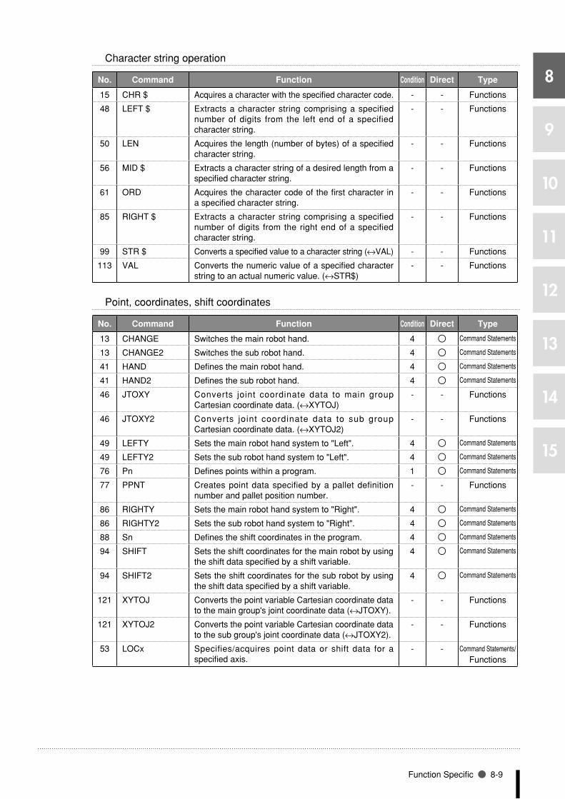
8
9
10
11
12
13
14
15
Function Specific 8-9
Character string operation
No1 Command Function Condition Direct Type
15 CHR $ Acquires a character with the specified character code. - - Functions
48 LEFT $ Extracts a character string comprising a specified number of digits from the left end of a specified character string.
- - Functions
50 LEN Acquires the length (number of bytes) of a specified character string.
- - Functions
56 MID $ Extracts a character string of a desired length from a specified character string.
- - Functions
61 ORD Acquires the character code of the first character in a specified character string.
- - Functions
85 RIGHT $ Extracts a character string comprising a specified number of digits from the right end of a specified character string.
- - Functions
99 STR $ Converts a specified value to a character string (↔VAL) - - Functions
113 VAL Converts the numeric value of a specified character string to an actual numeric value. (↔STR$)
- - Functions
Point, coordinates, shift coordinates
No1 Command Function Condition Direct Type
13 CHANGE Switches the main robot hand. 4 Command Statements
13 CHANGE2 Switches the sub robot hand. 4 Command Statements
41 HAND Defines the main robot hand. 4 Command Statements
41 HAND2 Defines the sub robot hand. 4 Command Statements
46 JTOXY Converts joint coordinate data to main group Cartesian coordinate data. (↔XYTOJ)
- - Functions
46 JTOXY2 Converts joint coordinate data to sub group Cartesian coordinate data. (↔XYTOJ2)
- - Functions
49 LEFTY Sets the main robot hand system to "Left". 4 Command Statements
49 LEFTY2 Sets the sub robot hand system to "Left". 4 Command Statements
76 Pn Defines points within a program. 1 Command Statements
77 PPNT Creates point data specified by a pallet definition number and pallet position number.
- - Functions
86 RIGHTY Sets the main robot hand system to "Right". 4 Command Statements
86 RIGHTY2 Sets the sub robot hand system to "Right". 4 Command Statements
88 Sn Defines the shift coordinates in the program. 4 Command Statements
94 SHIFT Sets the shift coordinates for the main robot by using the shift data specified by a shift variable.
4 Command Statements
94 SHIFT2 Sets the shift coordinates for the sub robot by using the shift data specified by a shift variable.
4 Command Statements
121 XYTOJ Converts the point variable Cartesian coordinate data to the main group's joint coordinate data (↔JTOXY).
- - Functions
121 XYTOJ2 Converts the point variable Cartesian coordinate data to the sub group's joint coordinate data (↔JTOXY2).
- - Functions
53 LOCx Specifies/acquires point data or shift data for a specified axis.
- - Command Statements/Functions

8-10 Chapter 8 Robot Language Lists
8
9
10
11
12
13
14
15
Branching commands
No1 Command Function Condition Direct Type
34 EXIT FOR Terminates the FOR to NEXT statement loop. 6 Command Statements
37 FOR to NEXT Controls repetitive operations. Executes the FOR to NEXT statement repeatedly until a specified value is reached.
6 Command Statements
38 GOSUB to RETURN
Jumps to a subroutine with the label specified by a GOSUB statement, and executes that subroutine.
6 Command Statements
39 GOTO Unconditionally jumps to the line specified by a label. 6 Command Statements
43 IF Allows control flow to branch according to conditions. 6 Command Statements
63 ON to GOSUB Jumps to a subroutine with labels specified by a GOSUB statement in accordance with the conditions, and executes that subroutine.
6 Command Statements
64 ON to GOTO Jumps to label-specified lines in accordance with the conditions.
6 Command Statements
89 SELECT CASE to END SELECT
Allows control flow to branch according to conditions. 6 Command Statements
119 WHILE to WEND Controls repeated operations. 6 Command Statements
Error control
No1 Command Function Condition Direct Type
62 ON ERROR GOTO
If an error occurs during program execution, this command allows the program to jump to the error processing routine specified by the label without stopping the program, or it stops the program and displays the error message.
6 Command Statements
83 RESUME Resumes program execution after error recovery processing.
6 Command Statements
33 ERL Gives the line No. where an error occurred. - - Functions
33 ERR Gives the error code number of an error which has occurred.
- - Functions
Program & task control
Program control
No1 Command Function Condition Direct Type
12 CALL Executes (calls) another program. 6 Command Statements
40 HALT Stops the program and performs a reset. 6 Command Statements
42 HOLD Temporarily stops the program. 6 Command Statements
103 SWI Switches the program being executed, performs compiling, then begins execution from the first line.
2 Command Statements
Task control
No1 Command Function Condition Direct Type
14 CHGPRI Changes the priority ranking of a specified task. 6 Command Statements
18 CUT Terminates a task currently being executed or temporarily stopped.
6 Command Statements
36 EXIT TASK Terminates its own task which is in progress. 6 Command Statements
82 RESTART Restarts another task during a temporary stop. 6 Command Statements
98 START Specifies the task number and priority ranking of a specified task, and starts that task.
6 Command Statements
102 SUSPEND Temporarily stops another task which is being executed. 6 Command Statements

8
9
10
11
12
13
14
15
Function Specific 8-11
Robot control
Robot operations
No1 Command Function Condition Direct Type
4 ABSRST Executes a return-to-origin at the robot absolute motor axes.
4 Command Statements
13 CHANGE Switches the main robot hand. 4 Command Statements
13 CHANGE2 Switches the sub robot hand. 4 Command Statements
29 DRIVE Moves a specified main group axis to an absolute position. 4 Command Statements
29 DRIVE2 Moves a specified sub group axis to an absolute position. 4 Command Statements
30 DRIVEI Moves a specified main group axis to a relative position. 4 Command Statements
30 DRIVEI2 Moves a specified sub group axis to a relative position. 4 Command Statements
41 HAND Defines the main robot hand. 4 Command Statements
41 HAND2 Defines the sub robot hand. 4 Command Statements
49 LEFTY Sets the main robot hand system to "Left". 4 Command Statements
49 LEFTY2 Sets the sub robot hand system to "Left". 4 Command Statements
58 MOVE Performs absolute movement of all main robot axes. 5 Command Statements
58 MOVE2 Performs absolute movement of all sub robot axes. 5 Command Statements
59 MOVEI Performs relative movement of all main robot axes. 4 Command Statements
59 MOVEI2 Performs relative movement of all sub robot axes. 4 Command Statements
67 ORIGIN Executes a return-to-origin for incremental specs. axes. 4 Command Statements
75 PMOVE Executes the main robot pallet movement command. 4 Command Statements
75 PMOVE2 Executes the sub robot pallet movement command. 4 Command Statements
86 RIGHTY Sets the main robot hand system to "Right". 4 Command Statements
86 RIGHTY2 Sets the sub robot hand system to "Right". 4 Command Statements
91 SERVO Controls the servo ON/OFF of specified main group axes or all main group axes.
4 Command Statements
91 SERVO2 Controls the servo ON/OFF of specified sub group axes or all sub group axes.
4 Command Statements
Status acquisition
No1 Command Function Condition Direct Type
3 ABSRPOS Acquires the machine reference of the specified main group axis. (Valid only for axes where the return-to-origin method is set as "mark method".)
- - Functions
3 ABSRPOS2 Acquires the machine reference of the specified sub group axis. (Valid only for axes where the return-to-origin method is set as "mark method".)
- - Functions
7 ARMCND Acquires the current arm status of the main robot. - - Functions
7 ARMCND2 Acquires the current arm status of the sub robot. - - Functions
8 ARMTYPE Acquires the current "hand system" setting of the main robot.
- - Functions
8 ARMTYPE2 Acquires the current "hand system" setting of the sub robot.
- - Functions
55 MCHREF Acquires the return-to-origin or absolute-search machine reference for a specified main group axis.
- - Functions
55 MCHREF2 Acquires the return-to-origin or absolute-search machine reference for a specified sub group axis.
- - Functions
111 TRQSTS Acquires the command end status for the DRIVE command with torque limit option executed at the main group.
- - Functions

8-12 Chapter 8 Robot Language Lists
8
9
10
11
12
13
14
15
No1 Command Function Condition Direct Type
111 TRQSTS2 Acquires the command end status for the DRIVE command with torque limit option executed at the sub group.
- - Functions
118 WHERE Reads out the current position of the main group robot arm in joint coordinates (pulses).
- - Functions
118 WHERE2 Reads out the current position of the sub group robot arm in joint coordinates (pulses).
- - Functions
120 WHRXY Reads out the current position of the main group arm as Cartesian coordinates (mm, degrees).
- - Functions
120 WHRXY2 Reads out the current position of the sub group arm as Cartesian coordinates (mm, degrees).
- - Functions
115 WAIT ARM Waits until the main group robot axis operation is completed.
115 WAIT ARM2 Waits until the sub group robot axis operation is completed.
6 × Command Statements
Status change
No1 Command Function Condition Direct Type
5 ACCEL Specifies/acquires the acceleration coefficient parameter of the main group.
4/- Command Statements/Functions
5 ACCEL2 Specifies/acquires the acceleration coefficient parameter of the sub group.
4/- Command Statements/Functions
6 ARCH Specifies/acquires the arch position parameter of the main group.
4/- Command Statements/Functions
6 ARCH2 Specifies/acquires the arch position parameter of the sub group.
4/- Command Statements/Functions
10 ASPEED Changes the AUTO movement speed of the main group.
4 Command Statements
10 ASPEED2 Changes the AUTO movement speed of the sub group.
4 Command Statements
11 AXWGHT Specifies/acquires the axis tip weight parameter of the main group.
4/- Command Statements/Functions
11 AXWGHT2 Specifies/acquires the axis tip weight parameter of the sub group.
4/- Command Statements/Functions
20 DECEL Specifies/acquires the deceleration rate parameter of the main group.
4/- Command Statements/Functions
20 DECEL2 Specifies/acquires the deceleration rate parameter of the sub group.
4/- Command Statements/Functions
66 ORGORD Specifies/acquires the axis sequence parameter for performing return-to-origin and absolute search operations in the main group.
4/- Command Statements/Functions
66 ORGORD2 Specifies/acquires the axis sequence parameter for performing return-to-origin and absolute search operations in the sub group.
4/- Command Statements/Functions
69 OUTPOS Specif ies/acquires the OUT enable posit ion parameter of the main group.
4/- Command Statements/Functions
69 OUTPOS2 Specif ies/acquires the OUT enable posit ion parameter of the sub group.
4/- Command Statements/Functions
74 PDEF Defines the pallet used to execute pallet movement commands.
1 Command Statements
97 SPEED Changes the main group's program movement speed.
4 Command Statements
97 SPEED2 Changes the sub group's program movement speed. 4 Command Statements

8
9
10
11
12
13
14
15
Function Specific 8-13
No1 Command Function Condition Direct Type
109 TOLE Specif ies/acquires the main group tolerance parameter.
4/- Command Statements/Functions
109 TOLE2 Specif ies/acquires the sub group tolerance parameter.
4/- Command Statements/Functions
116 WEIGHT Specif ies/acquires the main robot t ip weight parameter.
4/- Command Statements/Functions
116 WEIGHT2 Specif ies/acquires the sub robot t ip weight parameter.
4/- Command Statements/Functions
Path control
No1 Command Function Condition Direct Type
70 PATH Sets the movement path. 6 Command Statements
71 PATH END Ends the movement path setting. 6 Command Statements
72 PATH SET Starts the movement path setting. 6 Command Statements
73 PATH START Starts the PATH motion. 6 Command Statements
Torque control
No1 Command Function Condition Direct Type
17 CURTRQ Acquires the current torque value of the specified main group axis.
- Functions
17 CURTRQ2 Acquires the current torque value of the specified sub group axis.
- Functions
29 DRIVE (With T-option) Executes an absolute movement command for a specified axis.
4 Command Statements
110 TORQUE Specifies/acquires the maximum torque command value which can be set for a specified main group axis.
4/- Command Statements/Functions
110 TORQUE2 Specifies/acquires the maximum torque command value which can be set for a specified sub group axis.
4/- Command Statements/Functions
112 TRQTIME Specifies/acquires the current limit time-out period at the specified main group axis when using a torque limit option in the DRIVE statement.
1/- Command Statements/Functions
112 TRQTIME2 Specifies/acquires the current limit time-out period at the specified sub group axis when using a torque limit setting option in the DRIVE statement.
1/- Command Statements/Functions
Input/output & communication control
Input/output control
No1 Command Function Condition Direct Type
24 DELAY Waits for the specified period (units: ms). 6 Command Statements
28 DO Outputs a specified value to the DO port. 1 Command Statements
52 LO Outputs a specified value to the LO port to enable/disable axis movement.
1 Command Statements
57 MO Outputs a specified value to the MO port. 1 Command Statements
68 OUT Turns ON the bits of the specified output ports and the command statement ends.
6 Command Statements
81 RESET Turns the bit of a specified output port OFF. 1 Command Statements
92 SET Turns the bit at the specified output port ON. 3 In part Command Statements
96 SO Outputs a specified value to the SO port. 1 Command Statements

8-14 Chapter 8 Robot Language Lists
8
9
10
11
12
13
14
15
No1 Command Function Condition Direct Type
108 TO Outputs a specified value to the TO port. 1 Command Statements
114 WAIT Waits until the conditions of the DI/DO conditional expression are met (with time-out).
6 Command Statements
Programming box
No1 Command Function Condition Direct Type
44 INPUT Assigns a value to a variable specified from the programming box.
1 Command Statements
78 PRINT Displays a character string at the programming box screen.
1 Command Statements
Communication control
No1 Command Function Condition Direct Type
65 ONLINE Sets the specified communication port to the "online" mode.
1 Command Statements
60 OFFLINE Sets a specified communication port to the "offline" mode.
1 Command Statements
90 SEND Sends a file. 1 Command Statements
Other
Other
No1 Command Function Condition Direct Type
122 _SYSFLG Axis status monitoring flag. - - Functions

8
9
10
11
12
13
14
15
Functions: in alphabetic order 8-15
Functions: in alphabetic order
No1 Function Type Function
A1 ABS Arithmetic function Acquires the absolute value of a specified value.
3 ABSRPOS Arithmetic function Acquires the machine reference of the specified main group axis. (Valid only for axes where the return-to-origin method is set as "mark method".)
3 ABSRPOS2 Arithmetic function Acquires the machine reference of the specified sub group axis. (Valid only for axes where the return-to-origin method is set as "mark method".)
5 ACCEL Arithmetic function Acquires the acceleration coefficient parameter of the main group.
5 ACCEL2 Arithmetic function Acquires the acceleration coefficient parameter of the sub group.
6 ARCH Arithmetic function Acquires the arch position parameter of the main group.
6 ARCH2 Arithmetic function Acquires the arch position parameter of the sub group.
7 ARMCND Arithmetic function Acquires the current arm status of the main robot.
7 ARMCND2 Arithmetic function Acquires the current arm status of the sub robot.
8 ARMTYPE Arithmetic function Acquires the current "hand system" setting of the main robot.
8 ARMTYPE2 Arithmetic function Acquires the current "hand system" setting of the sub robot.
9 ATN Arithmetic function Acquires the arctangent of the specified value.
9 ATN2 Arithmetic function Acquires the arctangent of the specified X-Y coordinates.
11 AXWGHT Arithmetic function Acquires the axis tip weight parameter of the main group.
11 AXWGHT2 Arithmetic function Acquires the axis tip weight parameter of the sub group.
C15 CHR$ Character string
functionAcquires a character with the specified character code.
16 COS Arithmetic function Acquires the cosine value of a specified value.
17 CURTRQ Arithmetic function Acquires the current torque value of the specified main group axis.
17 CURTRQ2 Arithmetic function Acquires the current torque value of the specified sub group axis.
D19 DATE$ Character string
functionAcquires the date as a "yy/mm/dd" format character string.
20 DECEL Arithmetic function Acquires the deceleration rate parameter of the main group.
20 DECEL2 Arithmetic function Acquires the deceleration rate parameter of the sub group.
23 DEGRAD Arithmetic function Converts a specified value to radians (↔RADDEG).
26 DIST Arithmetic function Acquires the distance between 2 specified points.
E33 ERL Arithmetic function Gives the line No. where an error occurred.
33 ERR Arithmetic function Gives the error code number of an error which has occurred.
I45 INT Arithmetic function Acquires an integer for a specified value by truncating all
decimal fractions.
J46 JTOXY Point function Converts joint coordinate data to main group Cartesian
coordinate data. (↔XYTOJ)

8-16 Chapter 8 Robot Language Lists
8
9
10
11
12
13
14
15
No1 Function Type Function
46 JTOXY2 Point function Converts joint coordinate data to sub group Cartesian coordinate data. (↔XYTOJ2)
L48 LEFT$ Character string
functionExtracts a character string comprising a specified number of digits from the left end of a specified character string.
50 LEN Arithmetic function Acquires the length (number of bytes) of a specified character string.
53 LOCx Point function Acquires point data or shift data for a specified axis.
54 LSHIFT Arithmetic function Shifts a value to the left by the specified number of bits. (↔RSHIFT)
M55 MCHREF Arithmetic function Acquires the return-to-origin or absolute-search machine
reference for a specified main group axis.
55 MCHREF2 Arithmetic function Acquires the return-to-origin or absolute-search machine reference for a specified sub group axis.
56 MID$ Character string function
Extracts a character string of a desired length from a specified character string.
O61 ORD Arithmetic function Acquires the character code of the first character in a specified
character string.
66 ORGORD Arithmetic function Acquires the axis sequence parameter for performing return-to-origin and absolute search operations in the main group.
66 ORGORD2 Arithmetic function Acquires the axis sequence parameter for performing return-to-origin and absolute search operations in the sub group.
69 OUTPOS Arithmetic function Acquires the OUT enable position parameter of the main group.
69 OUTPOS2 Arithmetic function Acquires the OUT enable position parameter of the sub group.
P77 PPNT Point function Creates point data specified by a pallet definition number and
pallet position number.
R79 RADDEG Arithmetic function Converts a specified value to degrees. (↔DEGRAD)
85 RIGHT$ Character string function
Extracts a character string comprising a specified number of digits from the right end of a specified character string.
87 RSHIFT Arithmetic function Shifts a value to the right by the specified number of bits. (↔LSHIFT)
S95 SIN Arithmetic function Acquires the sine value for a specified value.
100 SQR Arithmetic function Acquires the square root of a specified value.
99 STR$ Character string function
Converts a specified value to a character string (↔VAL)
T104 TAN Arithmetic function Acquires the tangent value for a specified value.
105 TCOUNTER Arithmetic function Outputs count-up values at 10ms intervals starting from the point when the TCOUNTER variable is reset.
106 TIME$ Character string function
Acquires the current time as an "hh:mm:ss" format character string.
107 TIMER Arithmetic function Acquires the current time in seconds, counting from 12:00 midnight.
109 TOLE Arithmetic function Acquires the main group tolerance parameter.

8
9
10
11
12
13
14
15
Functions: in alphabetic order 8-17
No1 Function Type Function
109 TOLE2 Arithmetic function Acquires the sub group tolerance parameter.
110 TORQUE Arithmetic function Acquires the maximum torque command value which can be set for a specified main group axis.
110 TORQUE2 Arithmetic function Acquires the maximum torque command value which can be set for a specified sub group axis.
111 TRQSTS Arithmetic function Acquires the command end status for the DRIVE command with torque limit option executed at the main group.
111 TRQSTS2 Arithmetic function Acquires the command end status for the DRIVE command with torque limit option executed at the sub group.
112 TRQTIME Arithmetic function Acquires the current limit time-out period at the specified main group axis when using a torque limit option in the DRIVE statement.
112 TRQTIME2 Arithmetic function Acquires the current limit time-out period at the specified sub group axis when using a torque limit setting option in the DRIVE statement.
V113 VAL Arithmetic function Converts the numeric value of a specified character string to an
actual numeric value. (↔STR$)
W116 WEIGHT Arithmetic function Acquires the main robot tip weight parameter.
116 WEIGHT2 Arithmetic function Acquires the sub robot tip weight parameter.
118 WHERE Point function Reads out the current position of the main group robot arm in joint coordinates (pulses).
118 WHERE2 Point function Reads out the current position of the sub group robot arm in joint coordinates (pulses).
120 WHRXY Point function Reads out the current position of the main group arm as Cartesian coordinates (mm, degrees).
120 WHRXY2 Point function Reads out the current position of the sub group arm as Cartesian coordinates (mm, degrees).
X121 XYTOJ Point function Converts the point variable Cartesian coordinate data to the
main group's joint coordinate data (↔JTOXY).
121 XYTOJ2 Point function Converts the point variable Cartesian coordinate data to the sub group's joint coordinate data (↔JTOXY2).
122 _SYSFLG Arithmetic function Axis status monitoring flag.

8-18 Chapter 8 Robot Language Lists
8
9
10
11
12
13
14
15
Functions: operation-specific
Point related functions
No1 Function name Function
46 JTOXY Converts joint coordinate data to main group Cartesian coordinate data. (↔XYTOJ)
46 JTOXY2 Converts joint coordinate data to sub group Cartesian coordinate data. (↔XYTOJ2)
53 LOCx Acquires point data or shift data for a specified axis.
77 PPNT Creates point data specified by a pallet definition number and pallet position number.
118 WHERE Reads out the current position of the main group robot arm in joint coordinates (pulses).
118 WHERE2 Reads out the current position of the sub group robot arm in joint coordinates (pulses).
120 WHRXY Reads out the current position of the main group arm as Cartesian coordinates (mm, degrees).
120 WHRXY2 Reads out the current position of the sub group arm as Cartesian coordinates (mm, degrees).
121 XYTOJ Converts the point variable Cartesian coordinate data to the main group's joint coordinate data (↔JTOXY).
121 XYTOJ2 Converts the point variable Cartesian coordinate data to the sub group's joint coordinate data (↔JTOXY2).
Parameter related functions
No1 Function name Function
3 ABSRPOS Acquires the machine reference of the specified main group axis. (Valid only for axes where the return-to-origin method is set as "mark method".)
3 ABSRPOS2 Acquires the machine reference of the specified sub group axis. (Valid only for axes where the return-to-origin method is set as "mark method".)
5 ACCEL Acquires the acceleration coefficient parameter of the main group.
5 ACCEL2 Acquires the acceleration coefficient parameter of the sub group.
6 ARCH Acquires the arch position parameter of the main group.
6 ARCH2 Acquires the arch position parameter of the sub group.
7 ARMCND Acquires the current arm status of the main robot.
7 ARMCND2 Acquires the current arm status of the sub robot.
8 ARMTYPE Acquires the current "hand system" setting of the main robot.
8 ARMTYPE2 Acquires the current "hand system" setting of the sub robot.
11 AXWGHT Acquires the axis tip weight parameter of the main group.
11 AXWGHT2 Acquires the axis tip weight parameter of the sub group.
17 CURTRQ Acquires the current torque value of the specified main group axis.
17 CURTRQ2 Acquires the current torque value of the specified sub group axis.
20 DECEL Acquires the deceleration rate parameter of the main group.
20 DECEL2 Acquires the deceleration rate parameter of the sub group.
50 LEN Acquires the length (number of bytes) of a specified character string.
55 MCHREF Acquires the return-to-origin or absolute-search machine reference for a specified main group axis.
55 MCHREF2 Acquires the return-to-origin or absolute-search machine reference for a specified sub group axis.
61 ORD Acquires the character code of the first character in a specified character string.
66 ORGORD Acquires the axis sequence parameter for performing return-to-origin and absolute search operations in the main group.
66 ORGORD2 Acquires the axis sequence parameter for performing return-to-origin and absolute search operations in the sub group.
69 OUTPOS Acquires the OUT enable position parameter of the main group.
69 OUTPOS2 Acquires the OUT enable position parameter of the sub group.
109 TOLE Acquires the main group tolerance parameter.
109 TOLE2 Acquires the sub group tolerance parameter.
110 TORQUE Acquires the maximum torque command value which can be set for a specified main group axis.

8
9
10
11
12
13
14
15
Functions: operation-specific 8-19
No1 Function name Function
110 TORQUE2 Acquires the maximum torque command value which can be set for a specified sub group axis.
111 TRQSTS Acquires the command end status for the DRIVE command with torque limit option executed at the main group.
111 TRQSTS2 Acquires the command end status for the DRIVE command with torque limit option executed at the sub group.
112 TRQTIME Acquires the current limit time-out period at the specified main group axis when using a torque limit option in the DRIVE statement.
112 TRQTIME2 Acquires the current limit time-out period at the specified sub group axis when using a torque limit setting option in the DRIVE statement.
116 WEIGHT Acquires the main robot tip weight parameter.
116 WEIGHT2 Acquires the sub robot tip weight parameter.
Numeric calculation related functions
No1 Function name Function
1 ABS Acquires the absolute value of a specified value.
9 ATN Acquires the arctangent of the specified value.
9 ATN2 Acquires the arctangent of the specified X-Y coordinates.
16 COS Acquires the cosine value of a specified value.
23 DEGRAD Converts a specified value to radians (↔RADDEG).
26 DIST Acquires the distance between 2 specified points.
45 INT Acquires an integer for a specified value by truncating all decimal fractions.
54 LSHIFT Shifts a value to the left by the specified number of bits. (↔RSHIFT)
79 RADDEG Converts a specified value to degrees. (↔DEGRAD)
87 RSHIFT Shifts a value to the right by the specified number of bits. (↔LSHIFT)
95 SIN Acquires the sine value for a specified value.
100 SQR Acquires the square root of a specified value.
104 TAN Acquires the tangent value for a specified value.
113 VAL Converts the numeric value of a specified character string to an actual numeric value. (↔STR$)
Character string calculation related functions
No1 Function name Function
15 CHR $ Acquires a character with the specified character code.
19 DATE $ Acquires the date as a "yy/mm/dd" format character string.
48 LEFT $ Extracts a character string comprising a specified number of digits from the left end of a specified character string.
56 MID $ Extracts a character string of a desired length from a specified character string.
85 RIGHT $ Extracts a character string comprising a specified number of digits from the right end of a specified character string.
99 STR $ Converts a specified value to a character string (↔VAL)
Parameter related functions
No1 Function name Function
122 _SYSFLG Axis status monitoring flag.
33 ERL Gives the line No. where an error occurred.
33 ERR Gives the error code number of an error which has occurred.
105 TCOUNTER Outputs count-up values at 10ms intervals starting from the point when the TCOUNTER variable is reset.
106 TIME $ Acquires the current time as an "hh:mm:ss" format character string.
107 TIMER Acquires the current time in seconds, counting from 12:00 midnight.

8
A
B
C
D
E
F
G
H
I
J
K
L
M
8-20 Chapter 8 Robot Language Lists
1 ABSAcquires absolute values
Format
ABS (<expression>)
Explanation Returns a value specified by an <expression> as an absolute value.
SAMPLE
A=ABS(-326.55) ・・・・・・・・・・・・・・・・・・ The absolute value of -362.54 (=362.54) is assigned to variable A.
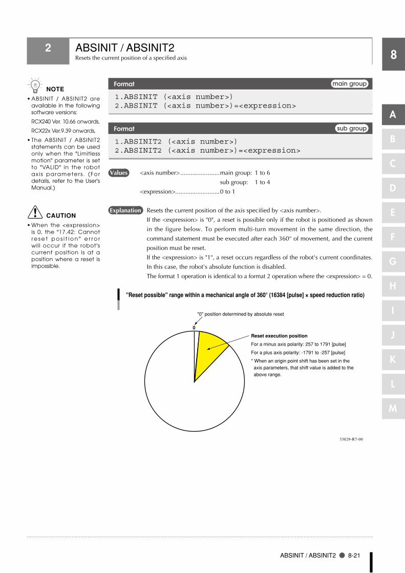
A
B
C
D
E
F
G
H
I
J
K
L
M
8
ABSINIT / ABSINIT2 8-21
2 ABSINIT / ABSINIT2Resets the current position of a specified axis
Format main group
1.ABSINIT (<axis number>)2.ABSINIT (<axis number>)=<expression>
Format sub group
1.ABSINIT2 (<axis number>)2.ABSINIT2 (<axis number>)=<expression>
Values <axis number> .......................main group: 1 to 6
sub group: 1 to 4
<expression>..........................0 to 1
Explanation Resets the current position of the axis specified by <axis number>.
If the <expression> is "0", a reset is possible only if the robot is positioned as shown
in the figure below. To perform multi-turn movement in the same direction, the
command statement must be executed after each 360° of movement, and the current
position must be reset.
If the <expression> is "1", a reset occurs regardless of the robot's current coordinates.
In this case, the robot's absolute function is disabled.
The format 1 operation is identical to a format 2 operation where the <expression> = 0.
0
Reset execution position
For a minus axis polarity: 257 to 1791 [pulse]
For a plus axis polarity: -1791 to -257 [pulse]
* When an origin point shift has been set in the axis parameters, that shift value is added to the above range.
"0" position determined by absolute reset
"Reset possible" range within a mechanical angle of 360° (16384 [pulse] × speed reduction ratio)
33829-R7-00
n NOTE
ABSINIT / ABSINIT2 are •available in the following software versions:
RCX240 Ver. 10.66 onwards,
RCX22x Ver.9.39 onwards,
The ABSINIT / ABSINIT2 •statements can be used only when the "Limitless motion" parameter is set to "VALID" in the robot ax i s parameters . (For details, refer to the User's Manual.)
c CAUTION
When the <expression> •is 0, the "17.42: Cannot r e s e t p o s i t i o n " e r r o r will occur if the robot's current position is at a position where a reset is impossible.

8
A
B
C
D
E
F
G
H
I
J
K
L
M
8-22 Chapter 8 Robot Language Lists
2 ABSINIT / ABSINIT2
SAMPLE
ABSINIT 1 ・・・・・・・・・・・・・・・・・・・・・・・・・ Resets the main group's 1st axis at the position where a current position reset is possible for that axis. (The same applies for ABSINIT 1, 0.)
ABSINIT2 1 ・・・・・・・・・・・・・・・・・・・・・・・・ Resets the sub group's 1st axis at the position where a current position reset is possible for that axis. (The same applies for ABSINIT2 1, 0.)
•Following the reset, the current position and target position values become values from which a distance equivalent to the motor's number-of-turns has been subtracted.
•Theresettimeperaxisisapproximately100ms.•Ifa "Limitlessmotion INVALID"axis is specified, the "5.37:Specificationmismatch"error
message displays, and execution is stopped.
Restrictions ●
1. Only the axis of a single-axis rotary type robot can be specified. Linear robot and dual robot
axes cannot be used.
2. The ABSINIT / ASBSINIT2 statements cannot be used at YC-Link specification axes.
3. The ABSINIT / ASBSINIT2 statements cannot be used at electric gripper specification axes.
MEMO

A
B
C
D
E
F
G
H
I
J
K
L
M
8
ABSRPOS / ABSRPOS2 8-23
3 ABSRPOS / ABSRPOS2Acquires a machine reference
Format main group
ABSRPOS (<axis 1>)
Format sub group
ABSRPOS2 (<axis 2>)
Values <axis 1> .................................main group: 1 to 6
<axis 2> .................................sub group: 1 to 4
Explanation The machine reference value for a specified <axis number> is acquired (units: %).
This function is valid only for axes where the return-to-origin method is set as "mark
method". It is not valid at axes where the return-to-origin method is set as "sensor" or
"stroke end".
•At axes where return-to-origin method is set to "mark" method, absolute reset is possible when
the machine reference value is in a 44 to 56% range.
SAMPLE
A=ABSRPOS(4) ・・・・・・・・・・・・・・・・・・・・・ The machine reference value for the main group's axis 4 is assigned to variable A.
MEMO

8
A
B
C
D
E
F
G
H
I
J
K
L
M
8-24 Chapter 8 Robot Language Lists
4 ABSRSTAbsolute motor axis return-to-origin operation
Format
ABSRST
Explanation This statement executes a direct return-to-origin operation for the robot's absolute
motor axes (absolute reset).
The return-to-origin will fail if the robot stops en route.
In systems with a two-robot setting, the main robot group return-to-origin occurs first,
followed by the sub robot group return-to-origin.
•This command is valid at axes where the return-to-origin method is set to other than "mark".
•Thiscommandcannotbeexecuted ifa return-to-origin is incompleteatanaxiswhere the
return-to-origin method is set as "mark".
•Insystemswithbothabsolutemotoraxesandincrementalmotoraxes,areturn-to-originwill
occur only at the absolute motor axes when the ABSRST command is executed.
•TheORIGINcommandmustbeusedtoperformareturn-to-originatincrementalmotoraxes.
Moreover, the return-to-origin operations occur in the parameter-specified sequence, and the
incremental motor axes will not operate.
SAMPLE
*ABS_RST:IF DI(20)=1 THEN ・・・・・・・・・・・・・・・ ABSRST executed when DI (20) is "1". ABSRSTENDIF*START:ABSRST ・・・・・・・・・・・・・・・・・・・ Absolute motor return-to-origin occurs.
Related commands ORIGIN, ORGORD, ORGORD2, MCHREF, MCHREF2
MEMO
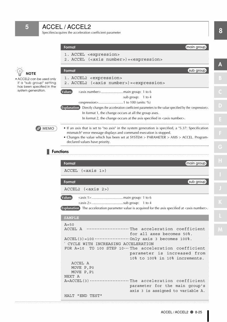
A
B
C
D
E
F
G
H
I
J
K
L
M
8
ACCEL / ACCEL2 8-25
5 ACCEL / ACCEL2Specifies/acquires the acceleration coefficient parameter
Format main group
1. ACCEL <expression> 2. ACCEL (<axis number>)=<expression>
Format sub group
1. ACCEL2 <expression> 2. ACCEL2 (<axis number>)=<expression>
Values <axis number> .......................main group: 1 to 6
sub group: 1 to 4
<expression>..........................1 to 100 (units: %)
Explanation Directly changes the acceleration coefficient parameters to the value specified by the <expression>.
In format 1, the change occurs at all the group axes.
In format 2, the change occurs at the axis specified in <axis number>.
•If an axis that is set to "no axis" in the system generation is specified, a "5.37: Specification mismatch" error message displays and command execution is stopped.
•ChangesthevaluewhichhasbeensetatSYSTEM>PARAMETER>AXIS>ACCEL.Program-declared values have priority.
Functions
Format main group
ACCEL (<axis 1>)
Format sub group
ACCEL2 (<axis 2>)
Values <axis 1> .................................main group: 1 to 6
<axis 2> .................................sub group: 1 to 4
Explanation The acceleration parameter value is acquired for the axis specified at <axis number>.
SAMPLE
A=50ACCEL A ・・・・・・・・・・・・・・・・・・・・・・・・・・ The acceleration coefficient
for all axes becomes 50%.ACCEL(3)=100 ・・・・・・・・・・・・・・・・・・・・・ Only axis 3 becomes 100%.’CYCLE WITH INCREASING ACCELERATIONFOR A=10 TO 100 STEP 10 ・・・ The acceleration coefficient
parameter is increased from 10% to 100% in 10% increments.
ACCEL A MOVE P,P0 MOVE P,P1NEXT AA=ACCEL(3) ・・・・・・・・・・・・・・・・・・・・・・・・ The acceleration coefficient
parameter for the main group's axis 3 is assigned to variable A.
HALT "END TEST"
n NOTE
ACCEL2 can be used only •if a "sub group" setting has been specified in the system generation.
MEMO

8
A
B
C
D
E
F
G
H
I
J
K
L
M
8-26 Chapter 8 Robot Language Lists
6 ARCH / ARCH2Specifies/acquires the acceleration coefficient parameter
Format main group
1. ARCH <expression> 2. ARCH (<axis number>)=<expression>
Format sub group
1. ARCH2 <expression> 2. ARCH2 (<axis number>)=<expression>
Values <axis number> .......................main group: 1 to 6
sub group: 1 to 4
<expression>..........................1 to 6144000 (Unit: pulses)
Explanation Changes the parameter's arch position to the value indicated in the <expression>.
In format 1, the change occurs at all the group axes.
In format 2, the change occurs at the arch position parameter for the axis specified in
<axis number> to the value specified in <expression>.
•If an axis that is set to "no axis" in the system generation is specified, a "5.37: Specification
mismatch" error message displays and command execution is stopped.
Functions
Format main group
ARCH (<axis 1>)
Format sub group
ARCH2 (<axis 2>)
Values <axis 1> .................................main group: 1 to 6
<axis 2> .................................sub group: 1 to 4
Explanation Acquires the arch position parameter value of the axis specified at <axis number>.
n NOTE
ARCH2 can be used only •if a "sub group" setting has been specified in the system generation.
MEMO

A
B
C
D
E
F
G
H
I
J
K
L
M
8
ARCH / ARCH2 8-27
6 ARCH / ARCH2
SAMPLE
DIM SAV(3)GOSUB *SAVE_ARCHFOR A=1000 TO 10000 STEP 1000 GOSUB *CHANGE_ARCH MOVE P,P0,Z=0 DO3(0)=1 ・・・・・・・・・・・・・・・・・・・・・・・ Chuck CLOSE MOVE P,P1,Z=0 DO3(0)=0 ・・・・・・・・・・・・・・・・・・・・・・・ Chuck OPENNEXT AGOSUB *RESTORE_ARCHHALT*CHANGE_ARCH:FOR B=1 TO 4 ・・・・・・・・・・・・・・・・・・・・・ The arch position parameters
ARCH (1) to (4) are assigned to array variables SAV (0) to (3).
ARCH(B)=ANEXT BRETURN*SAVE_ARCH:FOR B=1 TO 4 SAV(B-1)=ARCH(B)NEXT BRETURN*RESTORE_ARCH:FOR B=1 TO 4 ARCH(B)=SAV(B-1)NEXT B RETURN

8
A
B
C
D
E
F
G
H
I
J
K
L
M
8-28 Chapter 8 Robot Language Lists
7 ARMCND / ARMCND2Arm status acquisition
Format main group
ARMCND
Format sub group
ARMCND2
Explanation This function acquires the current arm status of the SCARA robot. The arm status is
"1" for a left-handed system and "0" for a right-handed system.
This function is enabled only when a SCARA robot is used.
SAMPLE
A=ARMCND ・・・・・・・・・・・・・・・・・・・・・・・・・・ The main robot's current arm status is assigned to variable A.
IF A=0 THEN ・・・・・・・・・・・・・・・・・・・・・・ Right-handed system status. MOVE P, P100, Z=0ELSE ・・・・・・・・・・・・・・・・・・・・・・・・・・ Left-handed system status. MOVE P, P200, Z=0ENDIF

A
B
C
D
E
F
G
H
I
J
K
L
M
8
ARMTYPE / ARMTYPE2 8-29
8 ARMTYPE / ARMTYPE2SCARA robot hand system
Format main group
ARMTYPE
Format sub group
ARMTYPE2
Explanation This function acquires the hand system currently selected for the SCARA robot.
The arm type is "0" for a right-handed system, and "1" for a right-handed system. This
function is enabled only when a SCARA robot is used.
SAMPLE
A=ARMTYPE ・・・・・・・・・・・・・・・・・・・・・・・・・ The main robot's arm type value is assigned.
IF A=0 THEN ・・・・・・・・・・・・・・・・・・・・・・ The arm type is a right-handed system. MOVE P,P100,Z=0ELSE ・・・・・・・・・・・・・・・・・・・・・・・・・・ The arm type is a left-handed system. MOVE P,P200,Z=0ENDIF
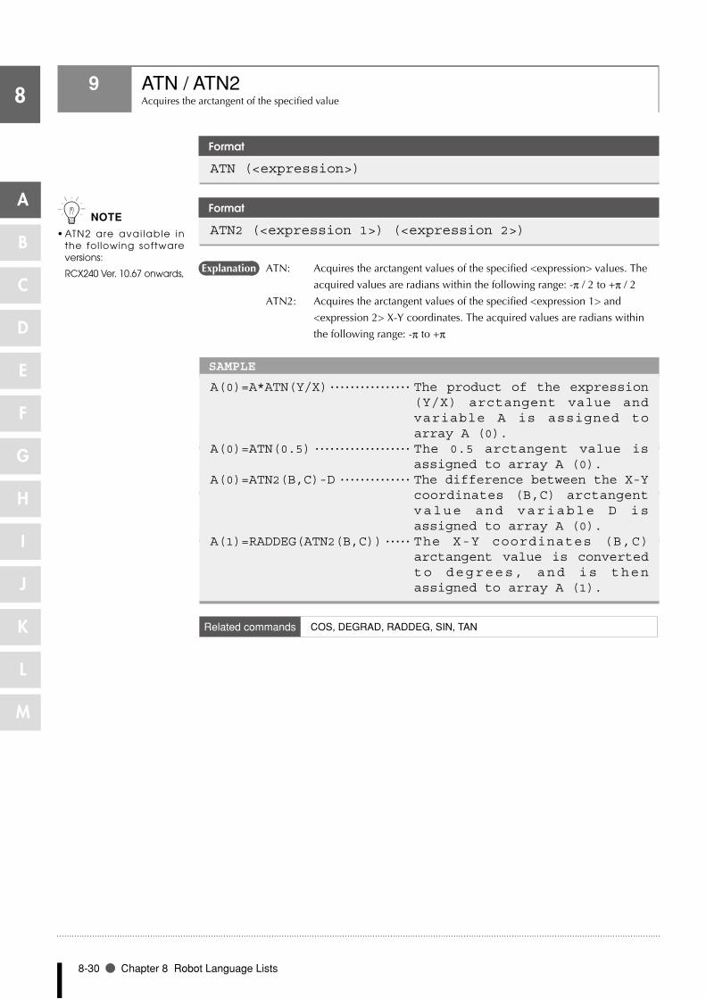
8
A
B
C
D
E
F
G
H
I
J
K
L
M
8-30 Chapter 8 Robot Language Lists
9 ATN / ATN2Acquires the arctangent of the specified value
Format
ATN (<expression>)
Format
ATN2 (<expression 1>) (<expression 2>)
Explanation ATN: Acquires the arctangent values of the specified <expression> values. The
acquired values are radians within the following range: -π / 2 to +π / 2
ATN2: Acquires the arctangent values of the specified <expression 1> and
<expression 2> X-Y coordinates. The acquired values are radians within
the following range: -π to +π
SAMPLE
A(0)=A*ATN(Y/X) ・・・・・・・・・・・・・・・・ The product of the expression (Y/X) arctangent value and variable A is assigned to array A (0).
A(0)=ATN(0.5) ・・・・・・・・・・・・・・・・・・・ The 0.5 arctangent value is assigned to array A (0).
A(0)=ATN2(B,C)-D ・・・・・・・・・・・・・・ The difference between the X-Y coordinates (B,C) arctangent value and variable D is assigned to array A (0).
A(1)=RADDEG(ATN2(B,C)) ・・・・・ The X-Y coordinates (B,C) arctangent value is converted to degrees, and is then assigned to array A (1).
Related commands COS, DEGRAD, RADDEG, SIN, TAN
n NOTE
ATN2 are avai lable in •the following software versions:
RCX240 Ver. 10.67 onwards,
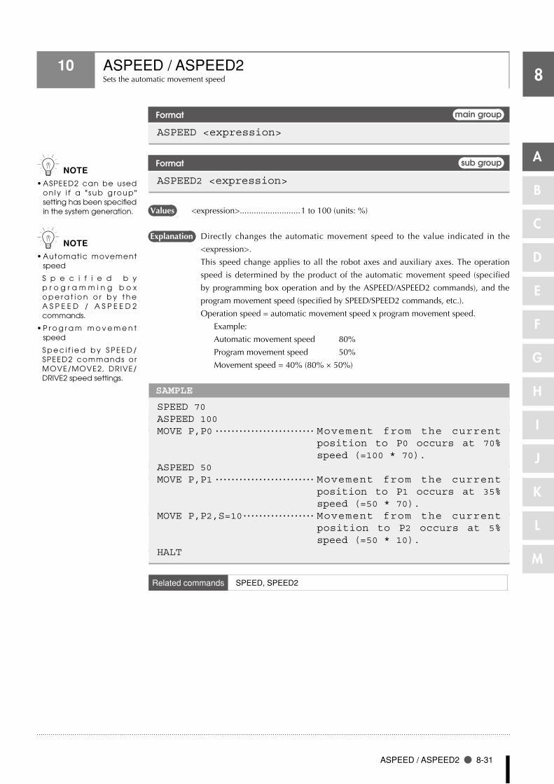
A
B
C
D
E
F
G
H
I
J
K
L
M
8
ASPEED / ASPEED2 8-31
10 ASPEED / ASPEED2Sets the automatic movement speed
Format main group
ASPEED <expression>
Format sub group
ASPEED2 <expression>
Values <expression>..........................1 to 100 (units: %)
Explanation Directly changes the automatic movement speed to the value indicated in the
<expression>.
This speed change applies to all the robot axes and auxiliary axes. The operation
speed is determined by the product of the automatic movement speed (specified
by programming box operation and by the ASPEED/ASPEED2 commands), and the
program movement speed (specified by SPEED/SPEED2 commands, etc.).
Operation speed = automatic movement speed x program movement speed.
Example:
Automatic movement speed 80%
Program movement speed 50%
Movement speed = 40% (80% × 50%)
SAMPLE
SPEED 70 ASPEED 100 MOVE P,P0 ・・・・・・・・・・・・・・・・・・・・・・・・・ Movement from the current
position to P0 occurs at 70% speed (=100 * 70).
ASPEED 50 MOVE P,P1 ・・・・・・・・・・・・・・・・・・・・・・・・・ Movement from the current
position to P1 occurs at 35% speed (=50 * 70).
MOVE P,P2,S=10 ・・・・・・・・・・・・・・・・・・ Movement from the current position to P2 occurs at 5% speed (=50 * 10).
HALT
Related commands SPEED, SPEED2
n NOTE
ASPEED2 can be used •on ly i f a " sub g roup" setting has been specified in the system generation.
n NOTE
Automatic movement •speed
S p e c i f i e d b y p r o g r a m m i n g b o x o p e r a t i o n o r b y t h e A S P E E D / A S P E E D 2 commands.
P r o g r a m m o v e m e n t •speed
S p e c i f i e d b y S P E E D /SPEED2 commands or MOVE/MOVE2, DRIVE/DRIVE2 speed settings.

8
A
B
C
D
E
F
G
H
I
J
K
L
M
8-32 Chapter 8 Robot Language Lists
11 AXWGHT / AXWGHT2Sets/acquires the axis tip weight
Format main group
AXWGHT (<axis number>)=<expression>
Format sub group
AXWGHT2 (<axis number>)=<expression>
Values <axis number> .......................main group: 1 to 6
sub group: 1 to 4
<expression>..........................Varies according to the specified robot.
Explanation Directly changes the axis tip weight parameter for the group's axis specified by the
<axis number> to the <expression> value.
This statement is valid in systems with "MULTI" axes and auxiliary axes (the robot
type and auxiliary axes are factory set prior to shipment).
Functions
Format main group
AXWGHT (<axis 1>)
Format sub group
AXWGHT2 (<axis 2>)
Values <axis 1> .................................main group: 1 to 6
<axis 2> .................................sub group: 1 to 4
Explanation Acquires the value axis tip weight parameter value for the axis specified by the
<expression>.
This statement is valid in systems with "MULTI" axes and auxiliary axes.
SAMPLE
A=5 B=0 C=AXWGHT(1) ・・・・・・・・・・・・・・・・・・・・・・ Axis tip weight value is
acquired (the current value is saved to variable C).
AXWGHT(1)=A DRIVE(1,P0)AXWGHT(1)=B DRIVE(1,P1)AXWGHT(1)=C ・・・・・・・・・・・・・・・・・・・・・・ The axis tip weight value is set again.HALT
Related commands WEIGHT, WEIGHT2
n NOTE
AXWGHT2 can be used •on ly i f a " sub g roup" setting has been specified in the system generation.

8
CALL 8-33
A
B
C
D
E
F
G
H
I
J
K
L
M
12 CALLCalls a sub-procedure
Format
CALL <label> [(<actual argument> [, <actual argument>…])]
Explanation This statement calls up sub-procedures defined by the SUB to END SUB statements.
The <label> specifies the same name as that defined by the SUB statement.
1. When a constant or expression is specified as an actual argument, its value is
passed on to the sub-procedure.
2. When a variable or array element is specified as an actual argument, its value
is passed on to the sub-procedure. It will be passed on as a reference if "REF" is
added at the head of the actual argument.
3. When an entire array (array name followed by parentheses) is specified as an
actual argument, it is passed along as a reference.
•CALL statements containing one actual argument can be used up to 15 times in succession.
Note that this number is reduced if commands which use stacks such as an IF statement or
GOSUB statement are used, or depending on the number of arguments in the CALL statement.
•AlwaysusetheENDSUBstatement toendasub-procedurewhichhasbeencalledwith the
CALL statement. If another statement such as GOTO is used to jump out of the sub- routine, a
"5.12: Stack overflow" error, etc., may occur.
SAMPLE 1
X%=4 Y%=5 CALL *COMPARE ( REF X%, REF Y% ) HALT ’SUB ROUTINE: COMPARE SUB *COMPARE ( A%, B% ) IF A% < B% THEN TEMP%=A% A%=B% B%=TEMP% ENDIF END SUB
SAMPLE 2
I = 1 CALL *TEST( I ) HALT ’SUB ROUTINE: TEST SUB *TEST X = X + 1 IF X < 15 THEN CALL *TEST( X ) ENDIF END SUB
Related commands SUB, END SUB, CALL, DECLARE, EXIT SUB, SHARED
n NOTE
When a value is passed •on to a sub-procedure, the original value of the actual argument will not be changed even if it is changed in the sub-procedure.
W h e n a r e f e r e n c e i s •p a s s e d o n t o a s u b -procedure, the original v a l u e o f t h e a c t u a l argument wi l l also be changed if it is changed in the sub-procedure.
For details, see Chapter •3 "8 Value Pass-Along & Reference Pass-Along".
MEMO

8
A
B
C
D
E
F
G
H
I
J
K
L
M
8-34 Chapter 8 Robot Language Lists
13 CHANGE / CHANGE2Switches the hand
Format main group
CHANGE Hn
Format sub group
CHANGE2 Hn
Values n: The range of hand Nos. which can specified for the main group differs from that for
the sub group.
main group ........... 0 to 3
sub group .............. 4 to 7
Explanation CHANGE / CHANGE2 are used to switch the robot hand.
Before hand switching can occur, the hands must be defined at the HAND / HAND2
statements. For details, see section "39 HAND / HAND2".
SAMPLE
HAND H1= 0 150.0 0.0 HAND H2= -5000 20.00 0.0 P1=150.00 300.00 0.00 0.00 0.00 0.00 CHANGE H2 ・・・・・・・・・・・・・・・・・・・・・・・・・ Changes to hand 2.MOVE P,P1 ・・・・・・・・・・・・・・・・・・・・・・・・・ Moves the hand 2 tip to P1 (1).CHANGE H1 ・・・・・・・・・・・・・・・・・・・・・・・・・ Changes to hand 1.MOVE P,P1 ・・・・・・・・・・・・・・・・・・・・・・・・・ Moves the hand 1 tip to P1 (2).HALT

8
CHGPRI 8-35
A
B
C
D
E
F
G
H
I
J
K
L
M
14 CHGPRIChanges the priority ranking of a specified task
Format
CHGPRI Tn, p
Values n: Task No ............................2 to 8
p: Task priority ranking .........17 to 47
Explanation Directly changes the priority ranking of the specified task ("n") to "p".
The priority ranking of the main task (Task 1) is fixed as 32. Even if a priority ranking
is not specified, "32" is adopted as the priority ranking for this task.
The smaller the priority number, the higher the priority (high priority: 17 ⇔ low
priority: 47).
When a READY status occurs at a task with higher priority, all tasks with lower
priority also remain in a READY status.
SAMPLE
START *SUBTASK,T2,33 *ST: MOVE P,P0,P1 IF DI(20) = 1 THEN CHGPRI T2,32 ELSE CHGPRI T2,33 ENDIF GOTO *ST HALT ’SUBTASK ROUTINE *SUBTASK: IF LOCZ(WHERE) > 10000 THEN DO(20) = 1 GOTO *SUBTASK ENDIF DO(20) = 0 GOTO *SUBTASK EXIT TASK
Related commands CUT, EXIT TASK, RESTART, SUSPEND, START

8
A
B
C
D
E
F
G
H
I
J
K
L
M
8-36 Chapter 8 Robot Language Lists
15 CHR$Acquires a character with the specified character code
Format
CHR$ (<expression>)
Values <expression>..........................0 to 255
Explanation Acquires a character with the specified character code. An error occurs if the
<expression> value is outside the 0 to 255 range.
SAMPLE
A$=CHR$(65) ・・・・・・・・・・・・・・・・・・・・・・ "A" is assigned to A$.
Related commands ORD

8
COS 8-37
A
B
C
D
E
F
G
H
I
J
K
L
M
16 COSAcquires the cosine value of a specified value
Format
COS (<expression>)
Values <expression>..........................Angle (units: radians)
Explanation Acquires a cosine value for the <expression> value.
SAMPLE
A(0)=B*COS(C) ・・・・・・・・・・・・・・・・・・・ The product of the C42 variable's cosine value and variable B is assigned to array A (0).
A(1)=COS(DEGRAD(20)) ・・・・・・・・ The 20.0 ° cosine value is assigned to array A (1).
Related commands ATN, DEGRAD, RADDEG, SIN, TAN
17 CURTRQ / CURTRQ2Acquires the current torque of the specified axis
Format main group
CURTRQ (<expression>)
Format sub group
CURTRQ2 (<expression>)
Values <expression>..........................1 to 6
Explanation Acquires the current torque value (-100 to 100) of the axis specified by the
<expression>. The current torque value is expressed as a percentage of the maximum
torque command value. Plus/minus signs indicate the direction.
SAMPLE
A = CURTRQ(3) ・・・・・・・・・・・・・・・・・・・ The current torque value of the main group's axis 3 is assigned to variable "A".
n NOTE
CURTRQ / CHKTRQ2 are •available in the following software versions:
RCX240 Ver. 10.65 onwards,
RCX22x Ver. 9.36 onwards
If the specified axis has •been set to "no axis" in the system generation, or if that axis uses the YC-Link or a power gripper, a "5 .37: Speci f icat ion mismatch" error message displays and command execution is stopped.

8
A
B
C
D
E
F
G
H
I
J
K
L
M
8-38 Chapter 8 Robot Language Lists
18 CUTTerminates another sub task which is currently being executed
Format
CUT Tn
Values n: Task No .............................2 to 8
Explanation Directly terminates another task which is currently being executed or which is
temporarily stopped.
This statement cannot terminate its own task, nor can it terminate Task 1.
SAMPLE
’TASK1 ROUTINE *ST: MO(20) = 0 START *SUBTASK2,T2 MOVE P,P0 MOVE P,P1 WAIT MO(20) = 1 CUT T2 GOTO *ST HALT ’TASK2 ROUTINE *SUBTASK2: P100=JTOXY(WHERE) IF LOCZ(P100) >= 100.0 THEN MO(20) = 1 ELSE DELAY 100 ENDIF GOTO *SUBTASK2 EXIT TASK
Related commands EXIT TASK, CUT, RESTART, START, SUSPEND

8
DATE$ 8-39
A
B
C
D
E
F
G
H
I
J
K
L
M
19 DATE$Acquires the date
Format
DATE$
Explanation Acquires the date as a "yy/mm/dd" format character string.
"yy" indicates the year (last two digits), "mm" indicates the month, and "dd" indicates
the day.
Date setting is performed at SYSTEM mode initial processing.
SAMPLE
A$=DATE$PRINT DATE$HALT
Related commands TIME$

8
8-40 Chapter 8 Robot Language Lists
A
B
C
D
E
F
G
H
I
J
K
L
M
20 DECEL / DECEL2Specifies/acquires the deceleration rate parameter
Format main group
1. DECEL <expression> 2. DECEL (<axis number>)=<expression>
Format sub group
1. DECEL2 <expression> 2. DECEL2 (<axis number>)=<expression>
Values <axis number> .......................main group: 1 to 6
sub group: 1 to 4
<expression>..........................1 to 100 (units: %)
Explanation Changes the deceleration rate parameter to the <expression> value.
In format 1, the change occurs at all the group axes.
In format 2, the change occurs at the axis specified in <axis number>.
•If an axis that is set to "no axis" in the system generation is specified, a "5.37: Specification
mismatch" error message displays and command execution is stopped.
•CommandstatementsDECEL/DECEL2canbeusedtochangetheaccelerationparameter.
Functions
Format main group
DECEL (<axis 1>)
Format sub group
DECEL2 (<axis 2>)
Values <axis 1> .................................main group: 1 to 6
<axis 2> ................................sub group: 1 to 4
Explanation Acquires the deceleration rate parameter value for the axis specified by the <expression>.
SAMPLE
A =50 DECEL A DECEL(3)=100 ’CYCLE WITH INCREASING DECELERATION FOR A =10 TO 100 STEP 10 DECEL A MOVE P ,P0 MOVE P ,P1 NEXT A A=DECEL(3) ・・・・・・・・・・・・・・・・・・・・・・・・ The deceleration rate parameter
for the main group's axis 3 is assigned to variable A.
HALT "END TEST "
n NOTE
T h e D E C E L / D E C E L 2 •s t a t e m e n t s a r e o n l y avai lable in sof tware version 8.15 onwards.
DECEL2 can be used only •if a "sub group" setting has been specified in the system generation.
MEMO

8
DECLARE 8-41
A
B
C
D
E
F
G
H
I
J
K
L
M
21 DECLAREDeclares that a sub-routine or sub-procedure is to be used within the COMMON program
Format
1. DECLARE <label> [, <label>…]2. DECLARE SUB <name> [(<dummy argument> [, <dummy argument>]…)]
Values <label> .................................. Label of the sub-routine defined in the COMMON
program.
<name> ................................. Name of the sub-procedure defined in the COMMON
program.
<dummy argument>............... Sub-procedure argument. Only the "number of
arguments" and the "data type" are significant.
Explanation Directly declares that a label or sub-procedure exists in the COMMON program. If a
sub-procedure is declared, the argument's data type is also checked.
This statement cannot be defined within a sub-procedure.
Because the DECLARE statement declares the existence of a label or sub-procedure
within the COMMON program, it cannot be used within the COMMON program
itself. The DECLARE statement is valid throughout the entire program.
SAMPLE
COMMON program shared labelProgram name: DIST1’================================================ ’ MAIN PROGRAM ’================================================ DECLARE *DISTANCE,*AREA X!=2. 5 Y!=1. 2 GOSUB *DISTANCE GOSUB *AREA HALT
Program name: COMMON ’================================================ ’ ’COMMON’PROGRAM ’================================================ *DISTANCE: PRINT SQR(X!^2+Y!^2)RETURN *AREA: PRINT X!*Y! RETURN
c CAUTION
O n l y t h e f o l l o w i n g •external labels can be used: GOSUB, CALL, ON to GOSUB.

8
8-42 Chapter 8 Robot Language Lists
A
B
C
D
E
F
G
H
I
J
K
L
M
21 DECLEAR
SAMPLE
External program shared sub-procedureProgram name: DIST2 ’====================================================== ’ MAIN PROGRAM ’====================================================== DECLARE SUB *DISTANCE(X!,Y!,D!) DECLARE SUB *AREA(X!,Y!,A!) CALL *DISTANCE(2. 5,1. 2,REF D!) PRINT D! CALL *AREA(2. 5,1. 2,REF A!) PRINT A! HALT Program name: COMMON ’======================================================’ ’COMMON’ PROGRAM ’====================================================== SUB *DISTANCE(X!,Y!,D!) D!=SQR(X!^2+Y!^2) END SUB SUB *AREA(X!,Y!,A!) A!=X!*Y! END SUB
Related commands CALL, EXIT SUB, GOSUB, ON to GOSUB, SUB, END SUB

8
DEF FN 8-43
A
B
C
D
E
F
G
H
I
J
K
L
M
22 DEF FNDefines functions which can be used by the user
Format
DEF FN <name> [ % ] [(<dummy argument>, [<dummy argument>…])] = <function definition expression> ! $
Values <name> ................................Function name. Max. of 16 chars., including "FN".
<dummy argument> ..............Numeric or character string variable.
Explanation Defines the functions which can be used by the user. Defined functions are called in
the FN <name> (<variable>) format.
•The <dummy argument> names are the same as the variable names used in the <function
definition expression>. The names of these variables are valid only when the <function
definition expression> is evaluated. There may be other variables with the same name in the
program.
•Whencallinga function thatusesa<dummyargument>,specify theconstant,variable,or
expression type which is the same as the <dummy argument> type.
•Ifavariableused in the<functiondefinitionexpression> isnot included in the<dummy
argument> list, the current value of that particular variable is used for the calculation.
•Aspacemustbeenteredbetween "DEF"and "FN". Ifnospace isentered,DEFFNwillbe
handled as a variable.
•TheDEFFNstatementcannotbeusedinsub-procedures.
•DefinitionbytheDEFFNstatementmustbedeclaredbeforestatementswhichusefunctions.
SAMPLE
DEF FNPAI=3.141592 DEF FNASIN(X)=ATN(X/SQR(-X^2+1)) ・・・・・・・・・・・・・・・・・・・・・・・・・・ Both the <dummy argument>
and <function definition expression> use "X".
・ ・ A=FNASIN(B)*10 ・・・・・・・・・・・・・・・・・・ "X" is not required for calling.
MEMO

8
8-44 Chapter 8 Robot Language Lists
A
B
C
D
E
F
G
H
I
J
K
L
M
23 DEGRADAngle conversion (angle → radian)
Format
DEGRAD (<expression>)
Values <expression>..........................Angle (units: degrees)
Explanation The <expression> value is converted to radians.
To convert radians to degrees, use RADDEG.
SAMPLE
A=COS(DEGRAD(30)) ・・・・・・・・・・・・・ A 30° cosine value is assigned to variable A.
Related commands ATN, COS, RADDEG, SIN, TAN

8
DELAY 8-45
A
B
C
D
E
F
G
H
I
J
K
L
M
24 DELAYProgram execution waits for a specified period of time
Format
DELAY <expression>
Values <expression>..........................1 to 3600000 (units: ms)
Explanation A "program wait" status is established for the period of time specified by the
<expression>. The minimum wait period is 10ms.
SAMPLE
DELAY 3500 ・・・・・・・・・・・・・・・・・・・・・・・・ 3,500ms (3.5 secs) waitDELAY A*10

8
8-46 Chapter 8 Robot Language Lists
A
B
C
D
E
F
G
H
I
J
K
L
M
25 DIAcquires the input status from the parallel port
Format
1. [LET] <expression> = DIm([b,・・・,b]) 2. [LET] <expression> = DI(mb,・・・,mb)
Values m ...........................................Port No.: 0 to 7, 10 to 17, 20 to 27
b ............................................Bit definition: 0 to 7
Explanation Indicates the parallel input signal status.
If multiple bits are specified, they are expressed from the left in descending order (large
to small).
Enter "0" if no input port exists.
If the [b,…,b] data is omitted, all 8 bits are processed.
SAMPLE
A%=DI2() ・・・・・・・・・・・・・・・・・・・・・・・・・・ The input status from DI (27) to DI (20) is assigned to variable A%.
A%=DI5(7,4,0) ・・・・・・・・・・・・・・・・・・ The DI (57), DI (54), DI (50) input status is assigned to variable A% (when all the above signals are "1" (ON), A% = 7).
A%=DI(37,25,20) ・・・・・・・・・・・・・・・・ The DI (37), DI (25), DI (20) input status is assigned to variable A% (when all the above signals except DI (20) are "1" (ON), A% = 6).
Reference For details, refer to Chapter 3 "9.5 Parallel input variable".

8
DIST 8-47
A
B
C
D
E
F
G
H
I
J
K
L
M
26 DISTAcquires the distance between 2 specified points
Format
DIST (<point expression 1>,<point expression 2>)
Values <point expression 1>..............Cartesian coordinate system point
<point expression 2>..............Cartesian coordinate system point
Explanation Acquires the distance (X,Y,Z)between the 2 points specified by <point expression 1>
and <point expression 2>. An error occurs if the 2 points specified by each <point
expression> do not have a Cartesian coordinates.
SAMPLE
A=DIST(P0,P1) ・・・・・・・・・・・・・・・・・・・ The distance between P0 and P1 is assigned to variable A.

8
8-48 Chapter 8 Robot Language Lists
A
B
C
D
E
F
G
H
I
J
K
L
M
27 DIMDeclares array variable
Format
DIM <array definition> [, <array definition>,…]
Format
<name> [ % ] (<constant> [, <constant> [, <constant>]]) ! $
Values <constant> ............................Array subscript: 0 to 32,767 (positive integer)
Explanation Directly declares the name and length (number of elements) of an array variable. A
maximum of 3 dimensions may be used for the array subscripts. Multiple arrays can
be declared in a single line by using comma ( , ) breakpoints to separate the arrays.
•Array subscripts can be "0 to a specified value", with their total number being the <constant> + 1.
•A"9.31:Memoryfull"errormayoccurdependingonthesizeofeachdimensiondefinedinan
array.
SAMPLE
DIM A%(10) ・・・・・・・・・・・・・・・・・・・・・・・・ Defines a integer array variable A% (0) to A% (10). (Number of elements: 11).
DIM B(2,3,4) ・・・・・・・・・・・・・・・・・・・・・ Defines a real array variable B (0, 0, 0) to B (2, 3, 4). (Number of elements: 60).
DIM C%(2,2),D!(10) ・・・・・・・・・・・・ Defines an integer array C% (0,0) to C% (2,2) and a real array D! (0) to D! (10).
MEMO

8
DO 8-49
A
B
C
D
E
F
G
H
I
J
K
L
M
28 DOOutputs to parallel port
Format
1. [LET] DOm ([b,・・・,b]) = <expression> 2. [LET] DO (mb,・・・,mb) = <expression>
Values m: Port No. ............................2 to 7, 10 to 17, 20 to 27
b: Bit definition ......................0 to 7
The output value is the lower left-side bit of the integer-converted <expression>
value.
Explanation Directly outputs the specified value to the DO port.
If multiple bits are specified, they are expressed from the left in descending order (large
to small).
No output will occur if a nonexistent DO port is specified.
If the [b,…,b] data is omitted, all 8 bits are processed.
Outputs are not possible to DO0() and DO1(). These ports are for referencing only.
SAMPLE
DO2() = &B10111000 ・・・・・・・・・・・・ DO (27, 25, 24, 23) are turned ON, and DO (26, 22, 21, 20) are turned OFF.
DO2(6,5,1) = &B010 ・・・・・・・・・・・・ DO (25) are turned ON, and DO (26, 21) are turned OFF.
DO3() = 15 ・・・・・・・・・・・・・・・・・・・・・・・・ DO (33, 32, 31, 30) are turned ON, and DO (37, 36, 35, 34) are turned OFF.
DO(37,35,27,20) = A ・・・・・・・・・・ The contents of the 4 lower bits acquired when variable A is converted to an integer are output to DO (37, 35, 27, 20) respectively.
Related commands RESET, SET

8
8-50 Chapter 8 Robot Language Lists
A
B
C
D
E
F
G
H
I
J
K
L
M
29 DRIVE / DRIVE2Executes absolute movement of specified axes
Format main group
DRIVE(<axis number>, <expression>)[,(<axis number>, <expression>)...] [, option]
Format sub group
DRIVE2(<axis number>, <expression>)[,(<axis number>, <expression>)...] [, option]
Values <axis number> .......................main group: 1 to 6
sub group: 1 to 4
<expression>.......................... Motor position (mm, degrees, pulses) or point
expression
Explanation Executes absolute movement commands for specified axes within a group.
This command is also used in the same way for the group's auxiliary axes.
•Movementtype:PTP movement of specified axis.
•Pointsettingmethod:Bydirectnumericvalueinputandpointdefinition.
•Options:Speedsetting,STOPONconditionssetting,torquelimitsetting,XYsetting.
movement direction setting.
Movement type
PTP (Point to Point) movement of specified axis: ●
PTP movement begins after positioning of all axes specified at <axis number> is complete (within
the tolerance range), and the command terminates when the specified axes enter the OUT
position range. When two or more axes are specified, they will reach their target positions
simultaneously.
If the next command following the DRIVE / DRIVE2 command is an executable command such
as a signal output command, that next command will start when the movement axis enters the
OUT position range. In other words, that next command starts before the axis arrives within the
target position tolerance range.
Example:
Signal output (DO, etc.) Signal is output when axis enters within OUT position range.
DELAYDELAY command is executed and standby starts, when axis enters the OUT position range.
HALTProgram stops and is reset when axis enters the OUT position range. Therefore, axis movement also stops.
HOLDProgram temporarily stops when axis enters the OUT position range. Therefore, axis movement also stops.
WAIT WAIT command is executed when axis enters the OUT position range.
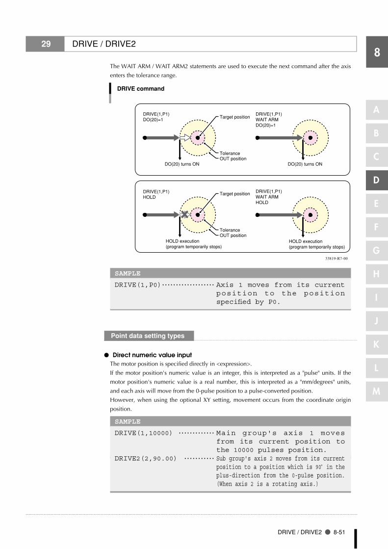
8
DRIVE / DRIVE2 8-51
A
B
C
D
E
F
G
H
I
J
K
L
M
29 DRIVE / DRIVE2
The WAIT ARM / WAIT ARM2 statements are used to execute the next command after the axis
enters the tolerance range.
P1
DO(20) turns ON
DRIVE(1,P1)WAIT ARMDO(20)=1
DO(20) turns ON
DRIVE(1,P1)DO(20)=1
Tolerance
Target position
OUT position
HOLD execution (program temporarily stops)
DRIVE(1,P1)WAIT ARMHOLD
DRIVE(1,P1)HOLD
ToleranceOUT position
Target position
HOLD execution (program temporarily stops)
DRIVE command
33819-R7-00
SAMPLE
DRIVE(1,P0) ・・・・・・・・・・・・・・・・・・・ Axis 1 moves from its current position to the position specified by P0.
Point data setting types
Direct numeric value input ●
The motor position is specified directly in <expression>.
If the motor position's numeric value is an integer, this is interpreted as a "pulse" units. If the
motor position's numeric value is a real number, this is interpreted as a "mm/degrees" units,
and each axis will move from the 0-pulse position to a pulse-converted position.
However, when using the optional XY setting, movement occurs from the coordinate origin
position.
SAMPLE
DRIVE(1,10000) ・・・・・・・・・・・・・ Main group's axis 1 moves from its current position to the 10000 pulses position.
DRIVE2(2,90.00) ・・・・・・・・・・・ Sub group's axis 2 moves from its current position to a position which is 90° in the plus-direction from the 0-pulse position. (When axis 2 is a rotating axis.)

8
8-52 Chapter 8 Robot Language Lists
A
B
C
D
E
F
G
H
I
J
K
L
M
29 DRIVE / DRIVE2
Point definition ●
Point data is specified in <expressions>. The axis data specified by the <axis number> is
used. If the point expression is in "mm/degrees" units, movement for each axis occurs from the
0-pulse position to the pulse-converted position.
However, when using the optional XY setting, movement occurs from the coordinate origin position.
SAMPLE
DRIVE(1,P1) ・・・・・・・・・・・・・・・・・ Main group's axis 1 moves from its current position to the position specified by P1.
DRIVE(4,P90) ・・・・・・・・・・・・・・・・・ Axis 4 moves from its current position to the position specified by P90 (deg) relative to the 0 pulse position. (When axis 4 is a rotating axis.)
Option types
Speed setting ●
Format
1. SPEED =<expression> 2. S =<expression>
Values <expression>..........................1 to 100 (units: %)
Explanation The program's movement speed is specified as an <expression>.
The actual speed is determined as shown below.
•Robot'smax.speed(mm/sec,ordeg/sec)×automaticmovementspeed(%)×
program movement speed (%).
This option is enabled only for the specified DRIVE/ DRIVE2 statement.
SAMPLE
DRIVE2(1,10000),S=10 ・・・・・ Sub group's axis 1 moves from its current position to the 10000 pulses position at 10% of the automatic movement speed.
Format
1. DSPEED =<expression>2. DS =<expression>
Values <expression>..........................0.01 to 100.00 (units: %)
Explanation The axis movement speed is specified in <expression>.
The actual speed is determined as shown below.
•Robot'smax.speed(mm/sec,ordeg/sec)×axismovementspeed(%).
This option is enabled only for the specified DRIVE/ DRIVE2 statement.
•MovementalwaysoccursattheDSPEED<expression>value(%)withoutbeing
affected by the automatic movement speed value (%).
SAMPLE
DRIVE2(1,10000),DS=0.1 ・・ Sub group's axis 1 moves from its current position to the 10000 pulses position at 0.1% of the robot's maximum speed.
n NOTE
If point data is specified •with both integers and real numbers in the same statement, all values are handled in "mm/degrees" units.
n NOTE
This defines the maximum •speed, and does not g u a r a n t e e t h a t a l l movement will occur at specified speed.
n NOTE
Speed setting (DSPEED) •is available only in the f o l l o w i n g s o f t w a r e versions:
RCX14x Ver. 8.71 onwards,
RCX22x Ver. 9.18 onwards
SPEED option and DSPEED •option cannot be used together

8
DRIVE / DRIVE2 8-53
A
B
C
D
E
F
G
H
I
J
K
L
M
29 DRIVE / DRIVE2
● STOPON conditions setting
Format
STOPON <conditional expression>
Explanation Stops movement when the conditions specified by the conditional expression are met. Because this is a deceleration type stop, there will be some movement (during deceleration) after the conditions are met.
If the conditions are already met before movement begins, no movement occurs, and the command is terminated.
This option is enabled only by program execution.
SAMPLE
DRIVE(1,10000),STOPON DI(20)=1 ・・・・・・・・・・・・・・ Axis 1 moves from its current position toward
the "10000 pulses" position and stops at an intermediate point if the "DI (20) = 1" condition is met. The next step is then executed.
•When the conditional expression used to designate the STOPON condition is a numeric
expression, the conditions for determining a TRUE or FALSE status can be changed at the
controller's "TRUE conditions" in the "Other parameters" mode.
These conditions apply to all the IF, WHILE, WAIT, STOPON, etc., conditional expressions. For
details, refer to the controller manual.
1) -1 (default setting) An expression value of "-1" indicates a TRUE status, and "0" indicates
a FALSE status. A "6.35: Incorrect condition expression" error occurs if
the expression value is other than "-1" or "0".
2) not 0 Any expression value other than "0" indicates a TRUE status, and "0"
indicates a FALSE status.
● Torque limit setting
Format
1. T =<torque limit value> 2. T =(<torque limit value> [,<torque offset value>])
Values <torque limit value>...............1 to 100 (units: %) <torque offset value> .............-100 to 100
Explanation Moves the axis while under torque control. The maximum torque at this time is limited to a value calculated as follows: Rated
torque × <torque limit value> / 100. A <torque offset value> is specified to control the torque at vertical axes, etc.,
where a fixed load is constantly applied. When the torque limit value setting is omitted, a setting of "0" is adopted (the setting is also "0" in Format 1).
Specify the torque offset value with reference to the value which displays at the current command monitor while axis movement is stopped by servo HOLD.
Note, however, that the value displayed at the current command monitor is the maximum torque ratio. As a general guideline, the torque offset value should be set as approximately 1/3 of the displayed value in order to acquire the rated torque ratio.
•The current command monitor can be displayed by pressing the [DISPLAY] key at the
programming box. For details, refer to the controller manual.
n NOTE
This parameter is only •available in the following software versions:
RCX14x Ver. 8.63 onwards
RCX22x Ver. 9.08 onwards
O n e a r l i e r v e r s i o n •controllers, -1 is "true" and a value other than -1 is "false" (not changeable).
MEMO
c CAUTION
The torque limit setting's •"torque offset setting" is available from software version 8.18 onwards.
The torque limit setting •c a n n o t b e u s e d a t axes where YC-L ink i s connected, or at axes where a power gripper is being used. Attempts to specify th is sett ing at these axes results in a "5 .37 Spec i f icat ion mismatch" message, and command execution is stopped.
The torque limit setting •range differs depending o n t h e r o b o t m o d e l . Sett ing a torque l imi t higher than the maximum level may cause robot malfunctions or failure.
If the specified torque •limit value is too small, the axis movement may not occur. Moreover, vertical axes may fall.
MEMO

8
8-54 Chapter 8 Robot Language Lists
A
B
C
D
E
F
G
H
I
J
K
L
M
29 DRIVE / DRIVE2
When the DRIVE / DRIVE2 statement is executed with this option specified, the axis
moves to the target position while controlling the torque by changing the maximum
torque for the axis to the <torque limit value>.
The maximum movement speed at this time is 10% of the normal operating speed.
No errors will occur even if the axis strikes an obstacle during movement, and the
axis torque (thrust) will not exceed the limit value.
•Command END conditions
1. The command ends when the axis has reached the target position.
2. The command ends when the time (timeout period) specified by the TRQTIME
/ TRQTIME2 statement has elapsed while the axis torque (thrust) has reached
the limit value.
•TRQSTS command value
1. 1 is set at the TRQSTS function when this command has ended due to a time-
out during which the axis torque has reached its limit value.
2. "0" is set if the command was ended for any other reason.
•Cautions
1. Maximum torque command values which have been changed by the TORQUE
/ TORQUE2 statements do not immediately become effective. They become
effective at the next movement command (MOVE or DRIVE statement, etc.).
2. Even after this command ends, the maximum torque limit and torque control
status remain in effect. The same applies if a stop occurs due to an interlock,
etc., while this command is being executed.
3. Torque control is canceled when an axis related operation is executed.
Such operations include servo ON/OFF switching, and a MOVE command
execution, etc.
4. To cancel the maximum torque limit, use the TORQUE statement to specify a
new maximum torque command value.
5. Maximum torque limit is cancelled at the following times regardless of
whether or not a TORQUE statement is used:
•WhenthecontrollerpoweristurnedON.
•WhentheservoisturnedOFF.
•Whenareturn-to-originoranabsolutereset(exceptbythemarkmethod)is
executed.
•Whenparameterdatahasbeenchangedorinitialized.
n NOTE
Conditions for ending this •command (descr ibed at right) are only valid f rom software vers ion 8.45 onwards. On earlier version controllers, this command ends at the following times:
1. When, at the po int when the time required to move to the target position has elapsed, the axis has reached the target position.
2. When, at the po int when the time required to move to the target position has elapsed, the ax i s torque has already reached the limit value for 1 second or longer.
3. When, at the po int when the time required to move to the target position has elapsed, the torque has reached the limit value, with this status continuing for 1 second or longer.
c CAUTION
In driver versions prior to •Ver.2.17, the maximum t o r q u e i n s t r u c t i o n i s enabled at the point when it is changed by the TORQUE / TORQUE2 statement.

8
DRIVE / DRIVE2 8-55
A
B
C
D
E
F
G
H
I
J
K
L
M
29 DRIVE / DRIVE2
•Restrictions
1. Two or more axes cannot be specified with this option.
2. Maximum movement speed is set as 10% of the normal operating speed.
3. Manual movement is not possible at axes which are under torque control (axes
where this command has been executed).
SAMPLE
TRQTIME(3)= 2500 ・・・・・・・・・・・ Sets the axis 3 torque control time-out period as 2.5 seconds.
DRIVE(3,P1),T= (20,15) ・・ Sets the maximum torque value to 20% of the rated torque, and the torque offset to 15, and moves the axis 3 from its current position to the point specified by P1 (pushing action).
IF TRQSTS(3)= 1 THEN ・・・・・ Checks to see if a time-out has occurred. DO(21)= 1 ・・・・・・・・・・・・・・・・・・・ Time-out occurred (pushing is complete).
(Result is output to DO(21) in this example.)ELSE DO(21)= 0 ・・・・・・・・・・・・・・・・・・・ Time-out has not occurred. (Reached
target position but failed to complete pushing.) (Result is output to DO(21) in this example.)
ENDIFTORQUE(3)= 100 ・・・・・・・・・・・・・・ Maximum torque command value is
returned to original value (100%).DRIVE(3,P0) ・・・・・・・・・・・・・・・・・・・ Torque limit and torque control
end, and movement to P0 occurs.
● XY setting
Format
XY
Explanation Moves multiple specified axes to a position specified by Cartesian coordinates.
All the specified axes arrive at the target position at the same time.
If all axes which can be moved by MOVE / MOVE2 statements have been
specified, operation is identical to that which occurs when using MOVE / MOVE2
statements.
The following restrictions apply to this command:
1. Axes specified by <axis number> must include the axis 1 and 2.
2. This command can be specified at SCARA robots and XY robots.
3. Point settings must be in "mm" or "deg" units (real number setting).
SAMPLE
DRIVE(1,P100),(2,P100),(4,P100),XY ・・・・・・・・・・・・・・ The axis 1, 2 and 4 move from their
current positions to the Cartesian coordinates position specified by P100.

8
8-56 Chapter 8 Robot Language Lists
A
B
C
D
E
F
G
H
I
J
K
L
M
29 DRIVE / DRIVE2
● Movement direction setting
Format
PLSMNS
Explanation <With a "movement direction setting">
•Movementoccurs in thespecifieddirection.APLSsettingalways results in
plus-direction movement, and a MNS setting always results in minus-direction
movement.
•Ifthetargetpositionandthecurrentpositionarethesame,a1-cyclemovement
amount occurs in the specified direction, then operation stops.
<Without a "movement direction setting">
•Movementoccursinthedirectioninwhichthemovementdistanceisshortest.
• If the targetpositionand thecurrentpositionare the same,nomovement
occurs.
•Cautions
1. When using this option, the maximum movement distance per operation is the
distance equivalent to 1 cycle (360°). If movement which exceeds the 1-cycle
distance is desired, the movement must be divided into 2 or more operations.
2. When using this option, the DRIVE statement's soft limit values are as shown
below.
Plus-direction soft limit: 67,000,000 [pulse]
Minus-direction soft limit: -67,000,000 [pulse]
• Restrictions
1. Only the axis of a single-axis rotary type robot can be specified.
2. Simultaneous movement of multiple axes is not possible when a movement
direct ion has been speci f ied. I f such movement is at tempted, the
"5.37: Specification mismatch" error will occur (see below).
Example: DRIVE (3,P1), (4,P1), PLS
3. The PLS and MNS options cannot both be specified simultaneously.
4. Attempting to use this option for a "limitless motion INVALID" axis will result
in the "2.29: Cannot move without the limit" error.
5. If a stop is executed by pressing the [STOP] key, etc., during movement which
uses this option (including during a deceleration), the movement distance when
restarted will be equivalent to a 1-cycle distance (360°).
n NOTE
The "movement direction •setting" option is available in the following software versions:
RCX240 Ver.10.66 onwards
RCX22x Ver.9.39 onwards

8
DRIVE / DRIVE2 8-57
A
B
C
D
E
F
G
H
I
J
K
L
M
29 DRIVE / DRIVE2
SAMPLE
DRIVE (4,270.00), PLS .......When the robot current position is 260°:
Moves 10° in the plus direction from the current position.
When the robot current position is 280°: Moves 350° in the plus direction from the current position.
DRIVE (4,270.00), MNS .......When the robot current position is 260°:
Moves 350° in the minus direction from the current position.
When the robot current position is 280°: Moves 10° in the minus direction from the current position.
DRIVE (4,270.00) .......When the robot current position is 260°:
Moves 10° in the plus direction from the current position.
When the robot current position is 280°: Moves 10° in the minus direction from the current position.
DRIVE2 (3,270.00), PLS .......When the robot current position is 260°:
Moves 10° in the plus direction from the current position.
When the robot current position is 280°: Moves 350° in the plus direction from the current position.
DRIVE2 (3,270.00), MNS .......When the robot current position is 260°:
Moves 350° in the minus direction from the current position.
When the robot current position is 280°: Moves 10° in the minus direction from the current position.
DRIVE2 (3,270.00) .......When the robot current position is 260°:
Moves 10° in the plus direction from the current position.
When the robot current position is 280°: Moves 10° in the minus direction from the current position.
Related commands TORQUE, TORQUE2, TRQTIME, TRQTIME2, TRQSYS, TRQSYS2, CURTRQ, CURTRQ2

8
8-58 Chapter 8 Robot Language Lists
A
B
C
D
E
F
G
H
I
J
K
L
M
30 DRIVEI / DRIVEI2Moves the specified robot axes in a relative manner
Format main group
DRIVEI(<axis number>, <expression>)[,(<axis number>, <expression>)...][,option]
Format sub group
DRIVEI2(<axis number>, <expression>)[,(<axis number>, <expression>)...][,option]
Values <axis number> .......................1 to 4
<expression>..........................Motor position (mm, deg, pulses) or point expression.
Explanation Directly executes relative movement of each axis of a group, including the group's
auxiliary axes.
•Movementtype: PTPmovementofaspecifiedaxis
•Pointdatasetting:Directcoordinatedatainput,pointdefinition
•Options: Speedsetting,STOPONconditionssetting
•When DRIVEI motion to the original target position is interrupted and then restarted, the target
position for the resumed movement can be selected as the "MOVEI/DRIVEI start position" in the
controller's "other parameters". For details, refer to the controller manual.
1) KEEP (default setting) Continues the previous (before interruption) movement. The original
target position remains unchanged.
2) RESET Relative movement begins anew from the current position. The new
target position is different from the original one (before interruption).
(Backward compatibility)
Movement type
PTP (point-to-point) of specified axis ●
PTP movement begins after positioning of all axes specified at <axis number> is complete (within
the tolerance range), and the command terminates when the specified axes enter the OUT
position range. When two or more axes are specified, they will reach their target positions
simultaneously.
If the next command following the DRIVEI / DRIVEI2 command is an executable command
such as a signal output command, that next command will start when the movement axis enters
the OUT position range. In other words, that next command starts before the axis arrives within
the target position tolerance range.
Example:
Signal output (DO, etc.) Signal is output when axis enters within OUT position range.
DELAYDELAY command is executed and standby starts, when axis enters the OUT position range.
HALTProgram stops and is reset when axis enters the OUT position range. Therefore, axis movement also stops.
HOLDProgram temporarily stops when axis enters the OUT position range. Therefore, axis movement also stops.
WAIT WAIT command is executed when axis enters the OUT position range.
MEMO
n NOTE
T h i s p a r a m e t e r i s •available in the following software version:
RCX14x Ver. 8.66 onwards
RCX22x Ver. 9.13 onwards
In version prior to those •shown above, a RESET must be performed at the controller.

8
DRIVEI / DRIVEI2 8-59
A
B
C
D
E
F
G
H
I
J
K
L
M
30 DRIVEI / DRIVEI2
The WAIT ARM / WAIT ARM2 statements are used to execute the next command after the axis
enters the tolerance range.
P1
DRIVEI command
WAIT ARM statement
DO(20) turns ON
DRIVEI(1,P1)WAIT ARMDO(20)=1
DO(20) turns ON
DRIVEI(1,P1)DO(20)=1
Tolerance
Target position
OUT position
HOLD execution (program temporarily stops)
DRIVEI(1,P1)WAIT ARMHOLD
DRIVEI(1,P1)HOLD
ToleranceOUT position
Target position
HOLD execution (program temporarily stops)
33820-R7-00
Limitless motion related cautions
•When the "limitlessmotion"parameter isenabled, theDRIVEI /DRIVEI2statementsoft limit
check values are as follows:
Plus-direction soft limit: 67,000,000 [pulse]
Minus-direction soft limit: -67,000,000 [pulse]
•WhenusingtheDRIVEI/DRIVEI2statements,theabovevaluesrepresentthemaximummovement
distance per operation.
SAMPLE
DRIVEI(1,P0) ・・・・・・・・・・・・・・・・・・・・・ The axis 1 moves from its current position to the position specified by P0.
n NOTE
The " l im i t les s mot ion" •function is available in the following software versions:
RCX240 Ver.10.66 onwards
RCX22x Ver.9.39 onwards

8
8-60 Chapter 8 Robot Language Lists
A
B
C
D
E
F
G
H
I
J
K
L
M
30 DRIVEI / DRIVEI2
Point data setting types
Direct numeric value input ●
The motor position is specified directly in <expression>.
If the motor position's numeric value is a real number, this is interpreted as a "mm / deg" units,
and each axis will move from the 0-pulse position to a pulse-converted position.
SAMPLE
DRIVEI(1,10000) ・・・・・・・・・・・ The axis 1 moves from its current position to the "+10000 pulses" position.
DRIVEI(4,90.00) ・・・・・・・・・・・ The axis 4 moves from its current position to the +90° position (when axis 4 is a rotating axis).
● Point definition Point data is specified in <expression>. The axis data specified by the <axis number> is used.
The motor position is determined in accordance with the point data defined by the point
expression. If the point expression is in "mm/degrees" units, movement for each axis occurs
from the 0-pulse position to the pulse-converted position.
SAMPLE
DRIVEI(1,P1) ・・・・・・・・・・・・・・・ The axis 1 moves from its current position the distance specified by P1.
DRIVEI(4,P90) ・・・・・・・・・・・・・・・・ The axis 4 moves from its current position the number of degrees specified by P90 (when axis 4 is a rotating axis).
n NOTE
If point data is specified •with both integers and real numbers in the same statement, all values are handled in "mm/degrees" units.

8
DRIVEI / DRIVEI2 8-61
A
B
C
D
E
F
G
H
I
J
K
L
M
30 DRIVEI / DRIVEI2
Option types
Speed setting ●
Format
1. SPEED=<expression>2. S=<expression>
Values <expression>..........................1 to 100 (units: %)
Explanation The program's movement speed is specified by the <expression>.
The actual speed is as follows:
•Robot'smax.speed(mm/sec,ordeg/sec)×automaticmovementspeed(%)×
program movement speed (%).
This option is enabled only for the specified DRIVEI / DRIVEI2 statement.
SAMPLE
DRIVEI(1,10000),S=10 ・・・・・ The axis 1 moves from its current position to the +10000 pulses position at 10% of the automatic movement speed.
Format
1. DSPEED=<expression>2. DS=<expression>
Values <expression>..........................0.01 to 100.00 (units: %)
Explanation The axis movement speed is specified as an <expression>.
The actual speed is determined as shown below.
•Robot'smax.speed(mm/sec,ordeg/sec)×axismovementspeed(%).
This option is enabled only for the specified DRIVEI / DRIVEI2 statement.
•MovementalwaysoccursattheDSPEED<expression>value(%)withoutbeing
affected by the automatic movement speed value (%).
SAMPLE
DRIVEI(1,10000),DS=0.1 ・・ The axis 1 moves from its current position to the +10000 pulses position at 0.1% of the automatic movement speed.
n NOTE
This defines the maximum •speed, and does not g u a r a n t e e t h a t a l l movement will occur at specified speed.
n NOTE
Speed setting (DSPEED) •is available only in the f o l l o w i n g s o f t w a r e versions:
RCX14x Ver. 8.71 onwards,
RCX22x Ver. 9.18 onwards
SPEED option and DSPEED •option cannot be used together.

8
8-62 Chapter 8 Robot Language Lists
A
B
C
D
E
F
G
H
I
J
K
L
M
30 DRIVEI / DRIVEI2
● STOPON conditions setting
Format
STOPON <conditional expression>
Explanation Stops movement when the conditions specified by the conditional expression
are met. Because this is a deceleration type stop, there will be some movement
(during deceleration) after the conditions are satisfied.
If the conditions are already satisfied before movement begins, no movement
occurs, and the command is terminated.
This option is enabled only by program execution.
•When the conditional expression used to designate the STOPON condition is a numeric
expression, the conditions for determining a TRUE or FALSE status can be changed at the
controller's "TRUE conditions" in the "Other parameters" mode. These conditions apply to all
the IF, WHILE, WAIT, STOPON, etc., conditional expressions. For details, refer to the controller
manual.
1) -1 (default setting) An expression value of "-1" indicates a TRUE status, and "0" indicates
a FALSE status.
A "6.35: Incorrect condition expression" error occurs if the expression
value is other than "-1" or "0".
2) not 0 Any expression value other than "0" indicates a TRUE status, and "0"
indicates a FALSE status.
SAMPLE
DRIVEI(1,10000),STOPON DI(20)=1 ・・・・・・・・・・・・・・ Axis 1 moves from its current position toward
the "+10000 pulses" position and stops at an intermediate point if the "DI (20) = 1" condition become satisfied. The next step is then executed.
MEMO
n NOTE
This parameter is only •available in the following software versions:
RCX14x Ver. 8.63 onwards
RCX22x Ver. 9.08 onwards
O n e a r l i e r v e r s i o n •controllers, -1 is "true" and a value other than -1 is "false" (not changeable).

8
END SELECT 8-63
A
B
C
D
E
F
G
H
I
J
K
L
M
31 END SELECTEnds the SELECT CASE statement
Format
SELECT [CASE] <expression> CASE <expression's list 1> [command block 1] CASE <expression's list 2> [command block 2] : [CASE ELSE [command block n]END SELECT
Explanation Directly ends the SELECT CASE command block.
For details, see section "87 SELECT CASE".
SAMPLE
WHILE -1 SELECT CASE DI3() CASE 1,2,3 CALL *EXEC(1,10) CASE 4,5,6,7,8,9,10 CALL *EXEC(11,20) CASE ELSE CALL *EXEC(21,30) END SELECT WEND HALT
Related commands SELECT CASE

8
A
B
C
D
E
F
G
H
I
J
K
L
M
8-64 Chapter 8 Robot Language Lists
32 END SUBEnds the sub-procedure definition
Format
SUB <label> [(<dummy argument> [, <dummy argument>…])] <command block>END SUB
Explanation Ends the sub-procedure definition which begins at the SUB statement.
For details, see section "99 SUB to ENDSUB".
SAMPLE 1
I=1 CALL *TEST PRINT I HALT ’SUB ROUTINE: TEST SUB *TEST I=50 END SUB
Related commands CALL, EXIT SUB, SUB to END SUB

8
ERR / ERL 8-65
A
B
C
D
E
F
G
H
I
J
K
L
M
33 ERR / ERLAcquires the error code / error line No
Format
ERRERL
Explanation Variables ERR and ERL are used in error processing routines specified by the ON
ERROR GOTO statement.
ERR gives the error code of the error that has occurred, and ERL gives the line number
in which the error occurred.
SAMPLE 1
IF ERR <> &H604 THEN HALTIF ERL=20 THEN RESUME NEXT
Related commands ON ERROR GOTO, RESUME

8
A
B
C
D
E
F
G
H
I
J
K
L
M
8-66 Chapter 8 Robot Language Lists
34 EXIT FORTerminates the FOR to NEXT statement loop
Format
EXIT FOR
Explanation Directly terminates the FOR to NEXT statement loop, then jumps to the command
which follows the NEXT statement.
This statement is valid only between the FOR to NEXT statements.
•The FOR to NEXT statement loop will end when the FOR statement condition is satisfied or
when the EXIT FOR statement is executed. A "5.12: Stack overflow" error, etc., will occur if
another statement such as GOTO is used to jump out of the loop.
SAMPLE
*ST: WAIT DI(20)=1 FOR A%=101 TO 109 MOVE P,P100,Z=0 DO(20)=1 MOVE P,P[A%],Z=0 DO(20)=0 IF DI(20)=0 THEN EXIT FOR NEXT A% GOTO *ST HALT
Related commands FOR, NEXT
MEMO

8
EXIT SUB 8-67
A
B
C
D
E
F
G
H
I
J
K
L
M
35 EXIT SUBTerminates the sub-procedure defined by SUB to END
Format
EXIT SUB
Explanation The EXIT SUB statement terminates the sub-procedure defined by the SUB to END
SUB statements, then jumps to the next command in the CALL statement that called
up the sub-procedure.
This statement is valid only within the sub-procedure defined by the SUB to END
SUB statements.
•To end the sub-procedure defined by the SUB to END SUB statements, use the END SUB
statement or EXIT SUB statement. A "5.12: Stack overflow" error, etc., will occur if another
statement such as GOTO is used to jump out of the loop.
SAMPLE
MAIN ROUTINE CALL *SORT2(REF X%,REF Y%) HALT ’SUB ROUTINE: SORT SUB *SORT2(X%, Y%) IF X%>=Y% THEN EXIT SUB TMP%=Y% Y%=X% X%=TMP% END SUB
Related commands CALL, SUB to END SUB, END SUB
MEMO

8
A
B
C
D
E
F
G
H
I
J
K
L
M
8-68 Chapter 8 Robot Language Lists
36 EXIT TASKTerminates its own task which is in progress
Format
EXIT TASK
Explanation Terminates its own task which is currently being executed.
This statement is valid for all tasks other than task 1 (Task 1 cannot be terminated).
•Even if a task that has started as a subtask jumps to another task processing routine with a
statement such as GO TO, that processing routine is then executed as this subtask processing.
SAMPLE
’TASK1 ROUTINE *ST: MO(20)=0 START *SUBTASK2,T2 MOVE P,P0,P1 WAIT MO(20)=1 GOTO *ST HALT ’TASK2 ROUTINE *SUBTASK2: P100=JTOXY(WHERE) IF LOCZ(P100)>=100.0 THEN MO(20)=1 EXIT TASK ENDIF DELAY 100 GOTO *SUBTASK2 EXIT TASK
Related commands CUT, RESTART, START, SUSPEND, CHGPRI
MEMO

A
B
C
D
E
F
G
H
I
J
K
L
M
8
FOR to NEXT 8-69
37 FOR to NEXTPerforms loop processing until the variable-specified value is exceeded
Format
FOR <control variable> = <start value> TO <end value> [STEP] <step>] <command block>NEXT [<control variable>]
Explanation These direct statements repeatedly execute commands between the FOR to NEXT
statements for the <start value> to <end value> number of times, while changing the
<control variable> value in steps specified by <STEP>. If <STEP> is omitted, its value
becomes "1".
The <STEP> value may be either positive or negative.
The <control variable> must be a numeric <simple variable> or <array variable>.
The FOR and NEXT statements are always used as a set.
SAMPLE
'CYCLE WITH CYCLE NUMBER OUTPUT TO DISPLAY FOR A=1 TO 10 MOVE P,P0 MOVE P,P1 MOVE P,P2 PRINT"CYCLE NUMBER=";A NEXT A HALT
Related commands EXIT FOR

8
A
B
C
D
E
F
G
H
I
J
K
L
M
8-70 Chapter 8 Robot Language Lists
38 GOSUB to RETURNJumps to a sub-routine
Format
GOSUB <label> * GOSUB can also be expressed as "GO SUB". : <label>: :RETURN
Explanation Jumps to the <label> sub-routine specified by the GOSUB statement.
A RETURN statement within the sub-routine causes a jump to the next line of the
GOSUB statement.
•The GOSUB statement can be used up to 29 times in succession. Note that this number of times
is reduced if commands containing a stack such as an IF statement or CALL statement are used.
•WhenajumptoasubroutinewasmadewiththeGOSUBstatement,alwaysusetheRETURN
statement to end the subroutine. If another statement such as GOTO is used to jump out of the
subroutine, an error such as "5.12: Stack overflow" may occur.
SAMPLE
*ST: MOVE P,P0 GOSUB *CLOSEHAND MOVE P,P1 GOSUB *OPENHAND GOTO *ST HALT ’SUB ROUTINE *CLOSEHAND: DO(20) = 1 RETURN *OPENHAND: DO(20) = 0 RETURN
Related commands RETURN
MEMO

8
GOTO 8-71
A
B
C
D
E
F
G
H
I
J
K
L
M
39 GOTOExecutes an unconditional jump to the specified line
Format
GOTO <label> * GOTO can also be expressed as "GO TO".
Explanation Executes an unconditional jump to the line specified by <label>.
To select a conditional jump destination, use the ON to GOTO, or IF statements.
SAMPLE
’MAIN ROUTINE *ST: MOVE P,P0,P1 IF DI(20) = 1 THEN GOTO *FIN ENDIF GOTO *ST *FIN: HALT

8
8-72 Chapter 8 Robot Language Lists
A
B
C
D
E
F
G
H
I
J
K
L
M
40 HALTStops the program and performs a reset
Format
HALT[ <expression> ] <character string>
Explanation Directly stops the program and resets it. If restarted after a HALT, the program runs
from its beginning.
•If an <expression> or <character string> is written in the statement, the contents of the
<expression> or <character string> are displayed on the programming box screen.
•Ifa"_SELECT"programnameexists,processingwillswitchtothat"_SELECT"programafterthe
HALT command is executed.
SAMPLE
’MAIN ROUTINE *ST: MOVE P,P0,P1 IF DI(20) = 1 THEN GOTO *FIN ENDIF GOTO *ST *FIN: HALT "PROGRAM FIN"
In PTP movement specified by movement commands such as MOVE and DRIVE, the next line's
command is executed when the axis enters the OUT position range.
Therefore, if a HALT command exists immediately after a PTP movement command, that HALT
command is executed before the axis arrives in the target position tolerance range.
Likewise, in interpolation movement during MOVE/MOVE2 commands, the next command is
executed immediately after movement starts. Therefore, if a HALT command exists immediately
after the interpolation movement command during MOVE/MOVE2, that HALT command is
executed immediately after movement starts.
In either of the above cases, use the WAIT ARM/WAIT ARM2 command if desiring to execute the
HALT command after the axis arrives within the target position tolerance range.
HALT execution
DRIVE(1,P1)WAIT ARMHALT
DRIVE(1,P1)HALT
ToleranceOUT position
Target position
HALT execution
HALT command
33821-R7-00
Reference For details regarding "_SELECT", see Chapter 1 "4 Program Names".
MEMO

8
HAND / HAND2 8-73
A
B
C
D
E
F
G
H
I
J
K
L
M
41 HAND / HAND2Defines the hand
Format main group
Definition statement: HAND Hn = <1st parameter> <2nd parameter> <3rd parameter> [R]Selection statement: CHANGE Hn
Format sub group
Definition statement: HAND2 Hn = <1st parameter> <2nd parameter> <3rd parameter> [R]Selection statement: CHANGE2 Hn
Values n: hand No .............................main group: 0 to 3 → HAND is used.
sub group: 4 to 7 → HAND2 is used.
Explanation The HAND / HAND2 statement only defines the hand. To actually change hands, the
CHANGE / CHANGE2 statement must be used.
For CHANGE / CHANGE2 statement details, see section "12 CHANGE / CHANGE2".
•If a power OFF occurs during execution of the hand definition statement, the "9.7 Hand check-
sum error" may occur.
41.1 For SCARA Robots
1. When the <4th parameter> “R” is not specified
Hands installed on the second arm tip are selected (see below).
<1st parameter> ............... Number of offset pulses between the standard second arm position
and the virtual second arm position of hand "n". "+" indicates the
counterclockwise direction [pulse].
<2nd parameter> .............. Difference between the hand "n" virtual second arm length and the
standard second arm length. [mm]
<3rd parameter> ............... Z-axis offset value for hand "n". [mm]
Hand 1 Hand 2
20.00mm
150.
00m
m
Stand
ard
2nd
arm
-5000 pulses
When the <4th parameter> "R" is not specified:
33801-R7-00
MEMO

8
8-74 Chapter 8 Robot Language Lists
A
B
C
D
E
F
G
H
I
J
K
L
M
41 HAND / HAND2
SAMPLE
HAND H1= 0 150.0 0.0 HAND H2= -5000 20.00 0.0 P1= 150.00 300.00 0.00 0.00 0.00 0.00 CHANGE H2 MOVE P,P1 ・・・・・・・・・・・・・・・・・・・・・・・・・ Tip of hand 2 moves to P1. CHANGE H1 MOVE P,P1 ・・・・・・・・・・・・・・・・・・・・・・・・・ Tip of hand 1 moves to P1. HALT
Y
X
Hand 2
(150.00, 300.00)Hand 1
X
Y
(150.00, 300.00)
SAMPLE:HAND
33802-R7-00

8
HAND / HAND2 8-75
A
B
C
D
E
F
G
H
I
J
K
L
M
41 HAND / HAND2
2. When the <4th parameter> "R" is specified
If the R-axis uses a servo motor, the hands that are offset from the R-axis rotating center are selected
(see below).
<1st parameter> ............... When the current position of R-axis is 0.00, this parameter shows
the angle of hand "n" from the X-axis plus direction in a Cartesian
coordinate system. ("+"indicates the counterclockwise direction.)
[degree]
<2nd parameter> .............. Length of hand "n". [mm] (>0)
<3rd parameter> ............... Z-axis offset amount for hand "n". [mm]
When the <4th parameter> "R" is specified
Standard 2nd arm 150.00mm
100.00mm Hand 2
Hand 1
X
Y
-90.00 deg.
33803-R7-00
SAMPLE
HAND H1= 0.00 150.0 0.0 RHAND H2= -90.00 100.00 0.0 RP1= 150.00 300.00 0.00 0.00 0.00 0.00CHANGE H1 MOVE P,P1 ・・・・・・・・・・・・・・・・・・・・・・・・・ Tip of hand 1 moves to P1. CHANGE H2 MOVE P,P1 ・・・・・・・・・・・・・・・・・・・・・・・・・ Tip of hand 2 moves to P1. HALT
SAMPLE:HAND
Y
X X
Y
Hand 1
(150.00, 300.00)
Hand 2
(150.00, 300.00)
33804-R7-00

8
8-76 Chapter 8 Robot Language Lists
A
B
C
D
E
F
G
H
I
J
K
L
M
41 HAND / HAND2
41.2 For Cartesian Robots
1. When the <4th parameter> "R" is not specified
Hands installed on the second arm tip are selected (see below).
<1st parameter> ............... Hand "n" X-axis offset amount [mm]
<2nd parameter> .............. Hand "n" Y-axis offset amount [mm]
<3rd parameter> ............... Hand "n" Z-axis offset amount [mm]
When the <4th parameter> "R" is not specified
-100.00mm
100.00mm
Hand 2
Hand 1
X
Y
33805-R7-00
SAMPLE
HAND H1= 0.00 0.00 0.00 HAND H2= 100.0 -100.0 -100.0 P1= 200.00 250.00 0.00 0.00 0.00 0.00 CHANGE H2 MOVE P,P1 ・・・・・・・・・・・・・・・・・・・・・・・・・ Tip of hand 2 moves to P1. CHANGE H1 MOVE P,P1 ・・・・・・・・・・・・・・・・・・・・・・・・・ Tip of hand 1 moves to P1. HALT
X
(200.00, 250.00)
Hand 2
Y
Hand 1
X
Y
(200.00, 250.00)
SAMPLE:HAND
33806-R7-00

8
HAND / HAND2 8-77
A
B
C
D
E
F
G
H
I
J
K
L
M
41 HAND / HAND2
2. When the <4th parameter> "R" is specified
If the R-axis uses a servo motor, the hands that are offset from the R-axis rotating center are selected
(see below).
<1st parameter> ............... When the current position of R-axis is 0.00, this parameter shows
the angle of hand "n" from the X-axis plus direction in a Cartesian
coordinate system. ("+"indicates the counterclockwise direction.)
[degree]
<2nd parameter> .............. Length of hand "n". [mm] (>0)
<3rd parameter> ............... Z-axis offset amount for hand "n". [mm]
When the <4th parameter> "R" is specified
X
Y
100.00mm
150.00mm
Hand2
Hand1
90 deg.
33807-R7-00
SAMPLE
HAND H1= 0.00 100.00 0.00 R HAND H2= 90.00 150.00 0.00 R P1= 200.00 250.00 0.00 0.00 0.00 0.00 CHANGE H2 MOVE P,P1 ・・・・・・・・・・・・・・・・・・・・・・・・・ Tip of hand 2 moves to P1. CHANGE H1 MOVE P,P1 ・・・・・・・・・・・・・・・・・・・・・・・・・ Tip of hand 1 moves to P1. HALT
SAMPLE:HAND
X
Hand 1
Y
(200.00, 250.00)
X
(200.00, 250.00)
Hand 2
Y
33808-R7-00

8
8-78 Chapter 8 Robot Language Lists
A
B
C
D
E
F
G
H
I
J
K
L
M
42 HOLDTemporarily stops the program
Format
HOLD[ <expression> ] <character string>
Explanation Temporarily stops the program. When restarted, processing resumes from the next
line after the HOLD statement. If an <expression> or <character string> is written in
the statement, the contents of the <expression> or <character string> display on the
programming box screen.
SAMPLE
’MAIN ROUTINE *ST: MOVE P,P0,P1 IF DI(20)=1 THEN HOLD "PROGRAM STOP" ENDIF GOTO *ST HALT
In PTP movement specified by movement commands such as MOVE and DRIVE, the next line's
command is executed when the axis enters the effective OUT position range.
Therefore, if a HOLD command exists immediately after a PTP movement command, that HOLD
command is executed before the axis arrives in the target position tolerance range.
Likewise, in interpolation movement during MOVE/MOVE2 commands, the next command is
executed immediately after movement starts. Therefore, if a HOLD command exists immediately
after the interpolation movement command during MOVE/MOVE2, that HOLD command is
executed immediately after movement starts.
In either of the above cases, use the WAIT ARM/WAIT ARM2 command if desiring to execute the
HOLD command after the axis arrives within the target position tolerance range.
HOLD command
HOLD execution
DRIVE(1,P1)WAIT ARMHOLD
DRIVE(1,P1)HOLD
ToleranceOUT position
Target position
HOLD execution
33822-R7-00

A
B
C
D
E
F
G
H
I
J
K
L
M
8
IF 8-79
43 IFEvaluates a conditional expression value, and executes the command in accordance with the conditions
•When the conditional expression used to designate the IF statement conditions is a numeric
expression, the conditions for determining a TRUE or FALSE status can be changed at the
controller's "TRUE conditions" in the "Other parameters" mode. These conditions apply to all
the IF, WHILE, WAIT, STOPON, etc., conditional expressions. For details, refer to the controller
manual.
1) -1 (default setting) An expression value of "-1" indicates a TRUE status, and "0" indicates
a FALSE status.
A "6.35 Incorrect condition expression" error occurs if the expression
value is other than "-1" or "0".
2) not 0 Any expression value other than "0" indicates a TRUE status, and "0"
indicates a FALSE status.
43.1 Simple IF statement
Format
IF <conditional expression> THEN <label 1> [ELSE <label 2> ] <command statement 1> <command statement 2>
Explanation If the condition specified by the <conditional expression> is met, processing jumps
either to the <label 1> which follows THEN, or to the next line after <command
statement 1> is executed.
If the condition specified by the <conditional expression> is not met, the following
processing occurs:
1. Processing either jumps to the <label 2> specified after the ELSE statement, or to
the next line after <command statement 2> is executed.
2. If nothing is specified after the ELSE statement, no action is taken, and processing
simply jumps to the next line.
SAMPLE
’MAIN ROUTINE *ST: MOVE P,P0,P1 IF DI(20)=1 THEN *L1 ・・・・ If DI (20) is "1", a jump to
*L1 occurs. DO(20)=1 DELAY 100 *L1: IF DI(21)=1 THEN *ST ELSE *FIN ・・・・・・・・・・・・・・・・・・・・・・・・・・ If DI (21) is "1", a jump to
*ST occurs. If other than "1", a jump to *FIN occurs.
*FIN: HALT
MEMO
n NOTE
This parameter is only •available in the following software versions:
RCX14x Ver. 8.63 onwards
RCX22x Ver. 9.08 onwards
O n e a r l i e r v e r s i o n •controllers, -1 is "true" and a value other than -1 is "false" (not changeable).

8
8-80 Chapter 8 Robot Language Lists
A
B
C
D
E
F
G
H
I
J
K
L
M
43 IF
43.2 Block IF statement
Format
IF <conditional expression 1> THEN <command block 1> [ELSEIF <conditional expression 2> THEN <command block 2>] [ELSE <command block n>] ENDIF
Explanation If the condition specified by <conditional expression 1> is met, this statement
executes the instructions specified in <command block 1>, then jumps to the next
line after ENDIF.
When an ELSEIF statement is present and the condition specified by <conditional
expression 2> is met, the instructions specified in <command block 2> are executed.
If all the conditions specified by the conditional expression are not met, <command
block n> is executed.
•The IF statement can be used up to 48 times in succession. Note that the maximum number of
times is reduced if commands containing a stack such as a GOSUB or CALL statement are used.
SAMPLE
’MAIN ROUTINE *ST: MOVE P,P0,P1 IF DI(21,20)=1 THEN DO(20)= 1 DELAY 100 WAIT DI(20)=0 ELSEIF DI(21,20)=2 THEN DELAY 100 ELSE GOTO *FIN ENDIF GOTO *ST *FIN: HALT
n NOTE
This parameter is only •available in the following software versions:
RCX14x Ver. 8.63 onwards
RCX22x Ver. 9.08 onwards
O n e a r l i e r v e r s i o n •controllers, -1 is "true" and a value other than -1 is "false" (not changeable).
MEMO

A
B
C
D
E
F
G
H
I
J
K
L
M
8
INPUT 8-81
44 INPUTAssigns a value to a variable specified from the programming box
Format
INPUT [<prompt statement> ; ] <variable> [, <variable> ,...] , <point variable> <point variable> <shift variable> <shift variable>
Explanation Assigns a value to the variable specified from the programming box.
The input definitions are as follows:
1. When two or more variables are specified by separating them with a comma ( , ),
the specified input data items must also be separated with a comma ( , ).
2. At the <prompt statement>, enter a character string enclosed in quotation marks
(" ") that will appear as a message requiring data input. When a semicolon ( ; ) is
entered following the prompt statement, a question mark ( ? ) and a space will
appear at the end of the message. When a comma ( , ) is entered, nothing will be
displayed following the message.
3. When the <prompt statement> is omitted, only a question mark ( ? ) and a space
will be displayed.
4. The input data type must match the type of the corresponding variables. When
data is input to a point variable or shift variable, insufficient elements are set to
"0".
5. If only the ENTER key is pressed without making any entry, the program interprets
this as a "0" or "null string" input. However, if specifying two or more variables, a
comma ( , ) must be used to separate them.
6. If the specified variable is a character type and a significant space is to be entered
before and after a comma ( , ), double quotation mark ( " ) or character string, the
character string must be enclosed in double quotation marks ( " ). Note that in this
case, you must enter two double quotation marks in succession so that they will
be identified as a double quotation mark input.
7. Pressing the ESC key skips this command.
•If the variable and the value to be assigned are different types, an "Input again" message displays
and a "waiting for input" status is established.
•Whenassigningalphanumericcharacterstoacharactervariable,itisnotnecessarytoenclose
the character string in double quotation marks ( " ).
SAMPLE
INPUT A INPUT "INPUT POINT NUMBER";A1 INPUT "INPUT STRING",B$(0),B$(1) INPUT P100 HALT
MEMO
8
8-82 Chapter 8 Robot Language Lists
A
B
C
D
E
F
G
H
I
J
K
L
M
45 INTTruncates decimal fractions
Format
INT (<expression>)
Explanation This function acquires an integer with decimal fractions truncated. The maximum
integer value which does not exceed the <expression> value is acquired.
SAMPLE
A=INT(A(0))B=INT(-1. 233) ・・・・・・・・・・・・・・・・・・ "-2" is assigned to B.

A
B
C
D
E
F
G
H
I
J
K
L
M
8
JTOXY / JTOXY2 8-83
46 JTOXY / JTOXY2Performs axis unit system conversions (pulse → mm)
Format main group
JTOXY (<point expression>)
Format sub group
JTOXY2 (<point expression>)
Explanation Converts the joint coordinate data (unit: pulses) specified by the <point expression>
into Cartesian coordinate data (unit: mm, deg.).
On YK500TW model robots, the X-arm and Y-arm rotation information is also set.
SAMPLE
P10=JTOXY(WHERE) ・・・・・・・・・・・・・・ Current position data is c o n v e r t e d t o C a r t e s i a n coordinate data.
Related commands XYTOJ, XYTOJ2
n NOTE
X-arm and Y-arm rotation •i n f o r m a t i o n i s o n l y avai lable in sof tware Ver.10.66 onwards.

8
8-84 Chapter 8 Robot Language Lists
A
B
C
D
E
F
G
H
I
J
K
L
M
47 LABEL StatementDefines labels at program lines
Format
*<label> :
Explanation Defines a <label> on a program line. A <label> must always begin with an asterisk
mark (*), and it must be located at the beginning of the line.
Although a colon mark (:) is required at the end of the <label> when defining it, this
mark is not required when specifying program jump destinations.
1. A <label> must begin with an alphabetic or numeric character.
2. Alphanumeric and underbars (_) can be used as the remaining <label> characters.
Special symbols, etc., cannot be used.
3. The <label> must not exceed 16 characters (all characters beyond the 16th
character are ignored).
SAMPLE
*ST: ・・・・・・・・・・・・・・・・・・・・・・・・・・ *ST label is defined. MOVE P,P0 DO(20) = 1 MOVE P,P1 DO(20) = 0GOTO *ST ・・・・・・・・・・・・・・・・・・・・・・・・・・ Jumps to *ST.HALT

8
LEFT$ 8-85
A
B
C
D
E
F
G
H
I
J
K
L
M
48 LEFT$Extracts character strings from the left end
Format
LEFT$ (<character string expression> , <expression>)
Values <expression>..........................0 to 75
Explanation This function extracts a character string with the digits specified by the <expression>
from the left end of the character string specified by <character string expression>.
The <expression> value must be between 0 and 75, otherwise an error will occur.
If the <expression> value is 0, then LEFT$ will be a null string (empty character
string).
If the <expression> value has more characters than the <character string expression>,
LEFT$ will become the same as the <character string expression>.
SAMPLE
B$=LEFT$(A$,4) ・・・・・・・・・・・・・・・・・ 4 characters from the left end of A$ are assigned to B$.
Related commands MID$, RIGHT$

8
8-86 Chapter 8 Robot Language Lists
A
B
C
D
E
F
G
H
I
J
K
L
M
49 LEFTY / LEFTY2Sets the SCARA robot hand system as a left-hand system
Format main group
LEFTY
Format sub group
LEFTY2
Explanation This statement specifies left-handed movement to a point specified in Cartesian
coordinates.
This statement only selects the hand system, and does not move the robot. If
executed while the robot arm is moving, execution waits until movement is complete
(positioned within tolerance range).
This command is only valid for SCARA robots.
SAMPLE
RIGHTY MOVE P,P1 LEFTY MOVE P,P1 RIGHTY HALT
SAMPLE:LEFTY/RIGHTY
P1
(1)(2)
Left-handed system Right-handed system
SCARA robot
33809-R7-00
Related commands RIGHTY, RIGHTY2
8
LEN 8-87
A
B
C
D
E
F
G
H
I
J
K
L
M
50 LENAcquires a character string length
Format
LEN(<character string expression>)
Explanation Returns the length (number of bytes) of the <character string expression>.
SAMPLE
B=LEN(A$)

8
8-88 Chapter 8 Robot Language Lists
A
B
C
D
E
F
G
H
I
J
K
L
M
51 LETAssigns values to variables
Format
[LET] <arithmetic assignment statement> <character string assignment statement> <point assignment statement> <shift assignment statement>
Explanation Directly executes the specified assignment statement. The right-side value is assigned
to the left side. An assignment statement can also be directly written to the program
without using a LET statement.
•If the controller power is turned off during execution of a <point assignment statement> or
<shift assignment statement>, a memory-related error such as the "9.2: Point check-sum error"
or the "9.6: Shift check-sum error" may occur.
1. Arithmetic assignment statement
Format
[LET] <arithmetic variable> = <expression> <point element variable> <shift element variable> <parallel output variable> <internal output variable> <arm lock output variable> <timer output variable> <serial output variable>
Values <expression>..........................Variable, function, numeric value
Explanation The <expression> value is assigned to the left-side variable.
SAMPLE
A!=B!+1 B%(1,2,3)=INT(10.88) LOCZ(P0)=A! LOCX(S1)=100.00 DO2()=&B00101101 MO(21,20)=2 LO(00)=1 TO(01)=0 SO12()=255
MEMO

8
LET 8-89
A
B
C
D
E
F
G
H
I
J
K
L
M
51 LET
2. Character string assignment statement
Format
[LET] <character string variable> = <character string expression>
Explanation The <character string expression> value is assigned to the character string variable.
Only the plus (+) arithmetic operator can be used in the <character string
expression>. Other arithmetic operators and parentheses cannot be used.
SAMPLE
A$ ="YAMAHA"B$ ="ROBOT"D$ = A$ + "-" + B$
Execution result: YAMAHA-ROBOT
•The "+" arithmetic operator is used to link character strings.
3. Point assignment statement
Format
[LET] <point variable> = <point expression>
Explanation Assigns <point expression> values to point variables.
Only 4 arithmetic operators ( +, - *, / ) can be used in the <point expression>.
Multiplication and division are performed only for constant or variable arithmetic
operations.
•Addition/subtraction ........ Addition/subtraction is performed for each element
of each axis.
•Multiplication .................. Multiplication by a constant or variable is performed
for each element of each axis.
•Division .......................... Division by a constant or variable is performed for
each element of each axis.
Multiplication results vary according to the point data type.
•Forpulseunits ................. Assigned after being converted to an integer.
•For"mm"units ................. Assigned after being converted to a real number
down to the 2nd decimal position.
MEMO

8
8-90 Chapter 8 Robot Language Lists
A
B
C
D
E
F
G
H
I
J
K
L
M
51 LET
SAMPLE
P1 =P10 ・・・・・・・・・・・・・・・・・・・・・ Point 10 is assigned to P1. P20=P20+P5 ・・・・・・・・・・・・・・・・・ Each element of point 20 and
point 5 is summed and assigned to P20.
P30=P30-P3 ・・・・・・・・・・・・・・・・・ Each element of point 3 is subtracted from point 30 and assigned to P30.
P80=P70*4・・・・・・・・・・・・・・・・・・・ Each element of point 70 is multiplied by 4 and assigned to P80.
P60=P5/3 ・・・・・・・・・・・・・・・・・・・・ Each element of point 5 is divided by 3 and assigned to P60.
•Multiplication & division examples are shown below.
•Permissibleexamples........ P15 * 5, P[E]/A, etc.
•Prohibitedexamples ......... P10 * P11, 3/P10, etc.
4. Shift assignment statement
Format
[LET] <shift variable> = <shift expression>
Explanation Assigns <shift expression> values to shift variables.
Only shift elements can be used in <shift expressions>, and only addition and
subtraction arithmetic operators are permitted. Parentheses cannot be used.
•Addition/subtraction ........ Addition/subtraction is performed for each element
of each axis.
SAMPLE
S1=S0 ・・・・・・・・・・・・・・・・・・・・・・・・ "shift 0" is assigned to "shift 1".
S2=S1+S0 ・・・・・・・・・・・・・・・・・・・・ Each element of "shift 1" and "shift 0" is summed and assigned to "shift 2".
•Examples of <shift expression> addition/subtraction:
•Permissibleexamples........ S1 + S2
•Prohibitedexamples ......... S1 + 3
MEMO
MEMO

8
LO 8-91
A
B
C
D
E
F
G
H
I
J
K
L
M
52 LOArm lock output
Format
1. LO0 ([b,・・・,b]) = <expression> 2. LO (0b,・・・,0b) = <expression>
Values b: Bit definition .....................0 to 7
<expression>.......................... Converted to an integer. The lower bits corresponding
to the bits specified on the left side are valid.
Explanation This statement outputs the specified value to the LO port to either prohibit or allow
axis movement.
LO(00) to LO(07) respectively correspond to axes 1 to 8. An arm lock ON status
occurs at axes where bits are set, and axis movement is prohibited. Multiple bits must
be specified in descending order from left to right (large → small).
•This statement is valid at axes where movement is started.
SAMPLE
LO0()=&B00001010 ・・・・・・・・・・・・・・ Prohibits movement at axes 2 and 4. LO0(2,1)=&B10 ・・・・・・・・・・・・・・・・・・ Prohibits movement at axis 3.
Related commands RESET, SET
MEMO

8
8-92 Chapter 8 Robot Language Lists
A
B
C
D
E
F
G
H
I
J
K
L
M
53 LOCxSpecifies/acquires point data or shift data for a specified axis
Format
1. LOCx (<point expression>) = <expression>2. LOCx (<shift expression>) = <expression>
Values Format 1: x ............................ X,Y,Z,R,A,B (axis setting), F (hand system flag setting),
F1 (X-arm rotation information), F2 (Y-arm rotation
information).
Format 2: x .............................X,Y,Z,R (axis setting)
<expression>..........................For axis setting: coordinate value.
For hand system flag setting:
1 (right-handed system) or 2 (left-handed system)
0 (no setting)
For specifies the X-arm rotation information and specifies
the Y-arm rotation information:
0, 1, -1
*1: For details regarding the X-arm and Y-arm rotation information, refer to
Chapter 4 "3. Point data format".
Explanation Direct format 1: Changes the value of the point data specified axis, the hand system
flag, and the X-arm and Y-arm rotation information.
Format 2: Changes the value of a specified axis from the shift data value.
•Points where data is to be changed must be registered in advance. An error will occur if a value
change is attempted at an unregistered point (where there are no coordinate values).
n NOTE
X-arm and Y-arm rotation •i n f o r m a t i o n i s o n l y avai lable in sof tware Ver.10.66 onwards.
MEMO

8
LOCx 8-93
A
B
C
D
E
F
G
H
I
J
K
L
M
53 LOCx
Functions
Format
1. LOCx (<point expression>)2. LOCx (<shift expression>)
Values Format 1: x ............................ X,Y,Z,R,A,B (axis setting), F (hand system flag setting),
F1 (X-arm rotation information), F2 (Y-arm rotation
information).
Format 2: x .............................X,Y,Z,R (axis setting)
Explanation Format 1: Acquires the value of the point data specified axis, the hand system flag,
and the X-arm and Y-arm rotation information.
Format 2: Acquires a specified axis value from the shift data.
SAMPLE
LOCX(P10)=A(1) ・・・・・・・・・・・・・・・・・・ The X-axis data of P10 is changed to the array A (1) value.
LOCY(S1)=B ・・・・・・・・・・・・・・・・・・・・・・・・ The Y-axis data of S1 is changed to the B value.
A(1)=LOCX(P10) ・・・・・・・・・・・・・・・・・・ The X-axis data of P10 is assigned to array A (1).
B(2)=LOCX(S1) ・・・・・・・・・・・・・・・・・・・ The X-axis data of S1 is assigned to array B (2).
Related commands Point element variable, shift element variable

8
8-94 Chapter 8 Robot Language Lists
A
B
C
D
E
F
G
H
I
J
K
L
M
54 LSHIFTLeft-shifts a bit
Format
LSHIFT (<expression 1> ,<expression 2>)
Explanation Shifts the <expression 1> bit value to the left by the amount of <expression 2>.
Spaces left blank by the shift are filled with zeros (0).
SAMPLE
A=LSHIFT(&B10111011,2) ・・・・・・ T h e 2 - b i t - l e f t - s h i f t e d &B10111011 value (&B11101100) is assigned to A.
Related commands RSHIFT
MCHREF / MCHREF2 8-95
8
A
B
C
D
E
F
G
H
I
J
K
L
M
55 MCHREF / MCHREF2Acquires a machine reference
Format main group
MCHREF (<axis 1>)
Format sub group
MCHREF2 (<axis 2>)
Values <axis 1> .................................main group: 1 to 6
<axis 2> .................................sub group: 1 to 4
Explanation This function provides the return-to-origin or absolute-search machine reference (unit:
%) for the axis specified by <axis number>.
This function can only be used for axes whose return-to-origin method is set to the
sensor or stroke end method.
SAMPLE
A=MCHREF(1) ・・・・・・・・・・・・・・・・・・・・・・ The main group's axis 1 return-to-origin machine reference is assigned to variable A.

8-96 Chapter 8 Robot Language Lists
8
A
B
C
D
E
F
G
H
I
J
K
L
M
56 MID$Acquires a character string from a specified position
Format
MID$ (<character string expression>,<expression 1>[,<expression 2>])
Values <expression 1>.......................1 to 75
<expression 2>.......................0 to 75
Explanation This function extracts a character string of a desired length (number of characters)
from the character string specified by <character string expression>. <expression 1>
specifies the character where the extraction is to begin, and <expression 2> specifies
the number of characters to be extracted.
An error will occur if the <expression 1> and <expression 2> values violate the
permissible value ranges.
If <expression 2> is omitted, or if the number of characters to the right of the
character of <expression 1> is less than the value of <expression 2>, then all
characters to the right of the character specified by <expression 1> will be extracted.
If <expression 1> is longer than the character string, MID$ will be a null string (empty
character string).
SAMPLE
B$=MID$(A$,2,4) ・・・・・・・・・・・・・・・・ The 2nd to 4th characters (up to the 5th char.) of A$ are assigned to B$.
Related commands LEFT$, RIGHT$

MO 8-97
8
A
B
C
D
E
F
G
H
I
J
K
L
M
57 MOOutputs a specified value to the MO port (internal output)
Format
1. MO0([b,・・・,b]) = <expression> 2. MO(0b,・・・,0b) = <expression>
Values m: port number ......................2 to 7, 10 to 17, 20 to 27
b: bit definition ......................0 to 7
<expression>.......................... The integer-converted lower bits corresponding to the
bit definition specified at the left side are valid.
Explanation Outputs a specified value to the MO port.
In order to maintain the sensor status and axis HOLD status at each axis, ports "0" and
"1" cannot be used as output ports (these ports are for referencing only).
If multiple bits are specified, they are expressed from the left in descending order (large
to small).
If the [b,…,b] data is omitted, all 8 bits are processed.
•Ports"0"and"1"outputs
Bit 7 6 5 4 3 2 1 0
Port 0 Axis 8 Axis 7 Axis 6 Axis 5 Axis 4 Axis 3 Axis 2 Axis 1
Origin sensor status 0: OFF; 1: ON
Port 1 Axis 8 Axis 7 Axis 6 Axis 5 Axis 4 Axis 3 Axis 2 Axis 1
HOLD status 0: No HOLD / 1: HOLD (1 axis is not used)
•For details regarding MO ports "0" and "1", see Chapter 3 "9.7 Internal output variable".
SAMPLE
MO2()=&B10111000 ・・・・・・・・・・・・・・・ MO (27, 25, 24, 23) are turned ON, and MO (26, 22, 21, 20) are turned OFF.
MO2(6,5,1)=&B010 ・・・・・・・・・・・・・・・ MO (25) are turned ON, and MO (26, 21) are turned OFF.
MO3() = 15 ・・・・・・・・・・・・・・・・・・・・・・・・ MO (33, 32, 31, 30) are turned ON, and MO (37, 36, 35, 34) are turned OFF.
MO(37,35,27,20)=A ・・・・・・・・・・・・・・ The contents of the 4 lower bits acquired when variable A is converted to an integer are output to MO (37, 35, 27, 20), respectively.
Related commands RESET, SET
参照REFERENCE
For details regarding bit •definitions, see Chapter 3 "10 Bit Settings".
MEMO

8-98 Chapter 8 Robot Language Lists
8
A
B
C
D
E
F
G
H
I
J
K
L
M
58 MOVE / MOVE2Performs absolute movement of all robot axes
Format main group
MOVE PTP , <point definition> [, option [, option] ...] P L C
Format sub group
MOVE2 PTP , <point definition> [, option [, option] ...] P L C
Explanation Executes direct absolute movement of a group's axes.
The MOVE command is used for axes which have been specified as main robot
axes, and the MOVE2 command is used for axes specified as sub robot axes. It is not
enabled for other groups, or for auxiliary axes.
•Movementtype: PTP,linearinterpolation,circularinterpolation.
•Pointdatasetting:Directcoordinatedatainput,pointdefinition.
•Options: Speedsetting,archmotionsetting,STOPONconditionsetting,
CONT setting, acceleration setting, deceleration setting, plane
coordinate setting, port output setting.
Options PTP Linear interpolation
Arch interpolation Remarks
Speed setting (SPEED) Enabled only for specified MOVE statement
Speed setting (VEL) Enabled only for specified MOVE statement
Arch motion Enabled only for specified MOVE statement
STOPON condition setting Enabled only by program execution
CONT setting Enabled only for specified MOVE statement
Acceleration setting Enabled only for specified MOVE statement
Deceleration setting Enabled only for specified MOVE statement
Plane coordinate setting Enabled only for specified MOVE statement
Port output setting Enabled only for specified MOVE statement
n NOTE
MOVE2 linear and circular •interpolation movement is supported in the following software versions:
RCX14x Ver. 8.64 onwards
RCX22x Ver. 9.11 onwards

MOVE / MOVE2 8-99
8
A
B
C
D
E
F
G
H
I
J
K
L
M
58 MOVE / MOVE2
Movement type
PTP (point-to-point) movement ●
Execution START condition: Movement of all specified axes is complete (within the tolerance
range).
Execution END condition: All specified axes have entered the OUT position range.
When two or more axes are specified, they will reach their target positions simultaneously. The
movement path of the axes is not guaranteed.
Caution regarding commands which follow the MOVE P / MOVE2 P command: ●
If the next command following the MOVE P / MOVE2 P command is an executable command
such as a signal output command, that next command will start when the movement axis enters
the OUT position range. In other words, that next command starts before the axis arrives within
the target position tolerance range.
Example:
Signal output (DO, etc.) Signal is output when axis enters within OUT position range.
DELAYDELAY command is executed and standby starts, when axis enters the OUT position range.
HALTProgram stops and is reset when axis enters the OUT position range. Therefore, axis movement also stops.
HOLDProgram temporarily stops when axis enters the OUT position range. Therefore, axis movement also stops.
WAIT WAIT command is executed when axis enters the OUT position range.
The WAIT ARM / WAIT ARM2 statements are used to execute the next command after the
axis enters the tolerance range.
•The OUT position value is specified by parameter setting.
This value can be changed from within the program by using the OUTPOS / OUTPOS2
commands.
P1
MOVE command
DO(20) turns ON
MOVE P,P1WAIT ARMDO(20)=1
DO(20) turns ON
MOVE P,P1DO(20)=1
Tolerance
Target position
OUT position
HOLD execution (program temporarily stops)
MOVE P,P1WAIT ARMHOLD
MOVE P,P1HOLD
ToleranceOUT position
Target position
HOLD execution (program temporarily stops)
33823-R7-00
MEMO

8-100 Chapter 8 Robot Language Lists
8
A
B
C
D
E
F
G
H
I
J
K
L
M
58 MOVE / MOVE2
SAMPLE
MOVE P,P0 ・・・・・・・・・・・・・・・・・・・・・・ The main robot axis moves from its current position to the position specified by P0 (the same occurs for MOVE PTP, P0).
•PTP movement is faster than interpolation movement, but when executing continuous
movement to multiple points, a positioning stop occurs at each point.
● Linear interpolation movementExecution START condition: Movement of all specified axes is complete (within the tolerance
range).
Execution END condition: Movement of all specified axes has begun.
Execution of the immediately following command occurs immediately after axis movement
begins.
When executing linear or circular interpolation in a continuous manner, the 2 movement paths
are linked by connecting the deceleration and acceleration sections, enabling continuous
movement without intermediate stops.
All movement axes arrive at the same time.
However, the following execution END condition applies if a STOPON condition has been
specified:
Execution END condition: Movement of all specified axes is complete (within the tolerance
range).
In this case, continuous movement for the 2 linked paths is not possible.
Caution regarding commands which follow a MOVE L / MOVE2 L command: ●
If the next command following the MOVE L / MOVE2 L command is an executable command
such as a signal output command, that next command will start immediately after axis
movement begins.
Example:
Signal output (DO, etc.) Signal is output immediately after movement begins.
DELAYDELAY command is executed and standby starts immediately after movement begins.
HALTProgram stops and is reset immediately after movement begins. Therefore, axis movement also stops.
HOLDProgram temporarily stops immediately after movement begins. Therefore, axis movement also stops.
WAIT WAIT command is executed immediately after movement begins.
The WAIT ARM / WAIT ARM2 statements are used to execute the next command after the
axis enters the tolerance range.
MEMO

MOVE / MOVE2 8-101
8
A
B
C
D
E
F
G
H
I
J
K
L
M
58 MOVE / MOVE2
•On RCX14x controllers earlier than Ver. 8.64, and RCX22x controllers earlier than Ver. 9.11,
linear interpolation can be performed by task 1 only.
•Smoothtravelpathsandconstantspeedsbetweenpathsmaynotalwaysbepossible,depending
on the axis movement speed, acceleration, and distance between the target points.
•OnrobotswithanR-axis,theR-axisspeedmaybecometoofastandcauseanerrordepending
on the R-axis movement distance.
•IfaDELAYstatement isexecutedafteraMOVEL /MOVE2Lcommand,aDELAYtimer is
activated after the MOVE L / MOVE2L command is executed. Therefore, if a DELAY is desired
after reaching the target point, use the WAIT ARM / WAIT ARM2 statement after the MOVE
command.
The same applies for other commands such as HALT, etc.
•If thedirectionchangesatanacuteangleduring interpolationmovement, theacceleration/
deceleration speed of the connection section may become too fast, causing an error. In this
case, specify a slower acceleration/deceleration speed at the connection section, or use the
WAIT ARM command to revise the operation pattern.
P1
MOVE command
DO(20) turns ON
MOVE L,P1WAIT ARMDO(20)=1
DO(20) turns ON
MOVE L,P1DO(20)=1
Tolerance
Target position
HOLD execution (program temporarily stops)
MOVE L,P1WAIT ARMHOLD
MOVE L,P1HOLD
Tolerance
Target position
HOLD execution (program temporarily stops)
33824-R7-00
SAMPLE
MOVE L,P0,P1 ・・・・・・・・・・・・・・・・・ The main robot axis moves from its current position to the position specified by P0, P1.
SAMPLE:MOVE L
P0
Current position
P1
Tolerance range
33810-R7-00
MEMO

8-102 Chapter 8 Robot Language Lists
8
A
B
C
D
E
F
G
H
I
J
K
L
M
58 MOVE / MOVE2
● Circular interpolation movementExecution START condition: Movement of all specified axes is complete (within the tolerance
range).
Execution END condition: Movement of all specified axes has begun.
Execution of the immediately following command occurs immediately after axis movement
begins.
When executing linear or circular interpolation in a continuous manner, the 2 movement paths
are linked by connecting the deceleration and acceleration sections, enabling continuous
movement without intermediate stops.
All movement axes arrive at the same time.
In circular interpolation, an arc is generated based on 3 points: the current position, an
intermediate position, and the target position. Therefore, circular interpolation must be
specified by an even number of points.
Caution regarding commands which follow a MOVE C / MOVE2 C command: ●
If the next command following the MOVE C / MOVE2 C command is an executable command
such as a signal output command, that next command will start immediately after axis
movement begins.
Example:
Signal output (DO, etc.) Signal is output immediately after movement begins.
DELAYDELAY command is executed and standby starts immediately after movement begins.
HALTProgram stops and is reset immediately after movement begins. Therefore, axis movement also stops.
HOLDProgram temporarily stops immediately after movement begins. Therefore, axis movement also stops.
WAIT WAIT command is executed immediately after movement begins.
The WAIT ARM / WAIT ARM2 statements are used to execute the next command after the
axis enters the tolerance range.
P1
MOVE command
DO(20) turns ON
MOVE C,P1,P2WAIT ARMDO(20)=1
DO(20) turns ON
MOVE C,P1,P2DO(20)=1
Tolerance
Target position
HOLD execution (program temporarily stops)
MOVE C,P1,P2WAIT ARMHOLD
MOVE C,P1,P2HOLD
Tolerance
Target position
HOLD execution (program temporarily stops)
33825-R7-00

MOVE / MOVE2 8-103
8
A
B
C
D
E
F
G
H
I
J
K
L
M
58 MOVE / MOVE2
SAMPLE
MOVE L,P20 ・・・・・・・・・・・・・・・・・・・・ Linear movement occurs from the current position to P20.
MOVE C,P21,P22,P23,P20 ・・ Arc movement occurs through points P21, P22, P23, P20.
MOVE L,P24 ・・・・・・・・・・・・・・・・・・・・ Linear movement occurs to P24.
SAMPLE:MOVE C
P23
Current position P24
P22
P21
P20
33811-R7-00
•In continuous interpolation operations, too, there are no stops at intermediate points. However,
the maximum speed is slower than the PTP speed.
•OnRCX14xcontrollersearlier thanVer.8.64,andRCX22xcontrollersearlier thanVer.9.11,
circular interpolation can be performed by task 1 only.
•Circularinterpolationispossiblewithinthefollowingrange:radius1.00mmto5,000.00mm.
•Circledistortionmayoccur,dependingonthespeed,acceleration,andthedistancebetween
points.
•OnrobotswithanR-axis,theR-axisspeedmaybecometoofastandcauseanerror,depending
on the R-axis movement distance.
•IfaDELAYstatement isexecutedafteraMOVEL /MOVE2Lcommand,aDELAYtimer is
activated after the MOVE L / MOVE2L command is executed. Therefore, if a DELAY is desired
after reaching the target point, use the WAIT ARM / WAIT ARM2 statement after the MOVE
statement.
The same applies for other commands such as HALT, etc.
•On"Multi" type robots, the "5.37 :Specificationmismatch"errorwilloccur,andcircular
interpolation will be disabled.
•If thedirectionchangesatanacuteangleduring interpolationmovement, theacceleration/
deceleration speed of the connection section may become too fast, causing an error. In this
case, specify a slower acceleration/deceleration speed at the connection section, or use the
WAIT ARM command to revise the operation pattern.
MEMO

8-104 Chapter 8 Robot Language Lists
8
A
B
C
D
E
F
G
H
I
J
K
L
M
58 MOVE / MOVE2
Movement command types and the corresponding movement
Current positionTolerance range
OUT position rangeTarget position
Current positionTolerance range
OUT position rangeTarget position
Current positionTolerance range
OUT position rangeTarget position
Current positionTolerance range
OUT position rangeTarget position
Command ends when movement enters the OUT position range, and the next command is then executed.
The next command is executed when movement arrives in the tolerance range.
The next command is executed when movement arrives in the tolerance range2).
1) If a DELAY statement is executed after an interpolation operation, a DELAY timer is activated immediately after the movement starts. Therefore, if a DELAY is desired after reaching the target point, use the WAIT ARM / WAIT ARM2 statement after the MOVE / MOVE2 command.2) A deceleration and stop occurs at an intermediate point if the condition specified by the STOPON conditional expression is met (for details, see the "STOPON Condition Setting" item).
Command ends immediately after movement begins, and the next command is immediately executed1).
1. PTP movement
2. Interpolation movement
3. WAIT ARM
4. STOPON conditional expression
33812-R7-00

MOVE / MOVE2 8-105
8
A
B
C
D
E
F
G
H
I
J
K
L
M
58 MOVE / MOVE2
Point data setting types
Direct numeric value input ● PTP Linear interpolation Circular interpolation
Format
X Y Z R A B [F] [F1] [F2]
Values X, Y, Z, R, A, B .......................Space-separated coordinate values for each axis.
F ............................................Hand system flag (SCARA robot only)
F1 ..........................................X-arm rotation information (YK500TW model only).
F2 ..........................................Y-arm rotation information (YK500TW model only).
Explanation Directly specifies coordinate values by a numeric value. If an integer is used, this
is interpreted as "pulse" units, and if a real number (with decimal point) is used,
this is interpreted as "mm/deg" units, with movement occurring accordingly. If
both integers and real numbers are used together (mixed), all coordinate values
will be handled in "mm/deg" units.
This setting method can be used only for PTP and linear interpolation movement types.
Hand system flags can be specified for SCARA robots when directly specifying the
coordinate values in "mm" units.
To specify an extended hand system flag for SCARA robots, set either 1 or 2 at "F".
If a number other than 1 or 2 is set, or if no number is designated, 0 will be set to
indicate that there is no hand system flag.
1: Right-handed system is used to move to a specified position. 2: Left-handed system is used to move to a specified position.
Direct numeric value inputs can be used to set the X-arm and Y-arm rotation
information (*1) only on YK500TW model robots where the coordinate system-of-
units has been set as "mm".
To set extended X-arm and Y-arm rotation information at the YK500TW model
robot, a "-1", "0", or "1" value must be specified at F1 and F2. Any other value, or
no X-arm and Y-arm rotation information at all, will be processed as "0".
0: Indicates arm rotation information where movement to the "0" position has
been specified.
1: Indicates arm rotation information where movement to the "1" position has
been specified.
-1: Indicates arm rotation information where movement to the "-1" position
has been specified.
*1: For details regarding the X-arm and Y-arm rotation information, refer to
Chapter 4 "3. Point data format".
•At SCARA robots with a hand system flag set in the movement destination's coordinate data, the
specified hand system will have priority over the current arm type or LEFTY/RIGHTY setting.
SAMPLE
MOVE P,10000 10000 1000 1000 0 0 ・・・・・・・・・・・・・・・・・・・・・・・・ PTP movement occurs from
current position to the specified position.
n NOTE
I f b o t h i n t e g e r s a n d •real numbers are used together (m ixed) , a l l coordinate values wi l l be handled in "mm/deg" units.
Hand system flags are •available from software version 8.08 onwards.
X-arm and Y-arm rotation •i n f o r m a t i o n i s o n l y avai lable in sof tware Ver.10.66 onwards.
c CAUTION
When performing linear •interpolation with a hand system f lag specif ied, be sure that the same hand system is used at the current position and target pos i t ion. I f the same hand system is not used, an error will occur and robot movement will be disabled.
When performing a linear •interpolation, the current p o s i t i o n ' s X - a r m a n d Y-arm rotation information must be the same as the movement destination's X-arm and Y-arm rotation information. If the two are different, an error will occur and movement will be disabled.
MEMO

8-106 Chapter 8 Robot Language Lists
8
A
B
C
D
E
F
G
H
I
J
K
L
M
58 MOVE / MOVE2
● Point definition PTP linear interpolation Circular interpolation
Format
<point expression>[,<point expression>...]
Explanation Specifies a <point expression>. Two or more data items can be designated by
separating them with a comma ( , ).
Circular interpolation must be specified by an even number of points.
•At SCARA robots with a hand system flag set in the movement destination's coordinate data, the
specified hand system will have priority over the current arm type or LEFTY/RIGHTY setting.
SAMPLE
MOVE P,P1 ・・・・・・・・・・・・・・・・・・・・ Moves from the current position to the position specified by P1.
MOVE P,P20,P0,P100 ・・・・・・・ Moves in sequence from the current position to positions specified by P20, P0, P100.
c CAUTION
When moving the robot •b y l i n e a r o r c i r c u l a r interpolation to a point where a hand system flag is specified, be sure that the same hand system is used at both the current and target positions. If the same hand system is not used, an error will occur and robot movement will be disabled.
MEMO
c CAUTION
When performing a linear •and circular interpolation, the cur rent pos i t ion ' s X-arm and Y-arm rotation information must be the same as the movement d e s t i n a t i o n ' s X - a r m a n d Y - a r m r o t a t i o n information. If the two are different, an error will occur and movement will be disabled.

MOVE / MOVE2 8-107
8
A
B
C
D
E
F
G
H
I
J
K
L
M
58 MOVE / MOVE2
Option types
Speed setting 1 ● PTP linear interpolation Circular interpolation
Format
1. SPEED = <expression> 2. S = <expression>
Values <expression>..........................1 to 100 (units: %)
Explanation Specifies the program speed in an <expression>.
The actual speed will be as follows:
•[Robotmax.speed(mm/sec)]×[automaticmovementspeed(%)]×[program
movement speed (%)].
This option is enabled only for the specified MOVE / MOVE2 statement.
SAMPLE
MOVE P,P10,S=10 ・・・・・・・・・・・ M o v e s f r o m t h e c u r r e n t position to the position specified by P10, at 10% of the program movement speed.
Speed setting 2 ● PTP linear interpolation Circular interpolation
Format
VEL = <expression>
Values <expression>..........................For SCARA robot: 1 to 750
For XY robot: 1 to 1000 (units: mm/sec)
Explanation Specifies the maximum composite speed (in "mm/sec" units) of the XYZ axes in
an <expression>. This option can be used for linear interpolation and circular
interpolation movements of SCARA robots or XY robots.
This option is enabled only for the specified MOVE / MOVE2 statement.
SAMPLE
MOVE L,P10,VEL=100 ・・・・・・・・ Moves from the current position to the position specified by P10, at the XYZ maximum composite speed of 100mm/sec.
n NOTE
This option specifies only •t h e m a x i m u m s p e e d and does not guarantee m o v e m e n t a t t h e specified speed.
n NOTE
This option specifies only •the maximum composite s p e e d a n d d o e s n o t guarantee movement at the specified speed.

8-108 Chapter 8 Robot Language Lists
8
A
B
C
D
E
F
G
H
I
J
K
L
M
58 MOVE / MOVE2
● Arch motion setting PTP linear interpolation Circular interpolation
Format
x = <expression>
Values x ............................................Specifies the X,Y,Z,R,A,B axis.
<expression>..........................An integer value is processed in "pulse" units.
A real number (with decimal point) is process in "mm/
deg" units.
Explanation 1. The "x" specified axis begins moving toward the position specified by the
<expression> (see "1" in the Fig. below).
2. When the "x" specified axis enters the arch position range, all other axes move
toward the target position (see "2" in the Fig. below).
3. When all axes other than the "x" specified axis enter the arch position range,
the "x" specified axis moves to the target position ("3" in the Fig. below).
4. The command ends when all axis enter the OUT position range.
This option can be used only for PTP movement.
If the "x" specified axis is the X or Y axis, the target position and <expression>
must be specified as an integer (pulse units) for SCARA robots and XY robots.
<expression> value: SCARA and XY type robots.
Target position value: SCARA type robot.
The values are indicated as the motor position rather than the coordinate values.
SAMPLE
MOVE P,P1,Z=0 ・・・・・・・・・・・・ Z-axis moves 0 pulses from its current position, then other axes move to P1. Finally, the Z-axis moves to P1.
SAMPLE:MOVE Z
Target position: P1Current position
1. Z-axis movement 3. Z-axis movement
2. Other axes movement
Z-axis arch position range
Other axes' arch position range
Z=0
33813-R7-00
n NOTE
The axis arch posit ion •p a r a m e t e r c a n b e c h a n g e d a t A R C H / ARCH2. The larger the value, the shorter the movement time.

MOVE / MOVE2 8-109
8
A
B
C
D
E
F
G
H
I
J
K
L
M
58 MOVE / MOVE2
STOPON condition setting ● PTP linear interpolation Circular interpolation
Format
STOPON <conditional expression>
Explanation Stops movement when the conditions specified by the conditional expression are
met. Because this is a deceleration type stop, there will be some movement (during
deceleration) after the conditions are met.
If the conditions are already met before movement begins, no movement occurs,
and the command is terminated.
This option can only be used for PTP movement and linear interpolation
movement.
This option is only possible by program execution.
SAMPLE
MOVE P,P100,STOPON DI(20)=1 ......... Moves from the current position to the position
specified by P100. If the "DI (20) = 1" condition is met during movement, a deceleration and stop occurs, and the next step is then executed.
•When the conditional expression used to designate the STOPON condition is a numeric
expression, the conditions for determining a TRUE or FALSE status can be changed at the
controller's "TRUE conditions" in the "Other parameters" mode. These conditions apply to all
the IF, WHILE, WAIT, STOPON, etc., conditional expressions. For details, refer to the controller
user's manual.
1) -1 (default setting) An expression value of "-1" indicates a TRUE status, and "0" indicates
a FALSE status.
A "6.35 Incorrect condition expression" error occurs if the expression
value is other than "-1" or "0".
2) not 0 Any expression value other than "0" indicates a TRUE status, and "0"
indicates a FALSE status.
MEMO
n NOTE
This parameter is only •available in the following software versions:
RCX14x Ver. 8.63 onwards
RCX22x Ver. 9.08 onwards
O n e a r l i e r v e r s i o n •controllers, -1 is "true" and a value other than -1 is "false" (not changeable).

8-110 Chapter 8 Robot Language Lists
8
A
B
C
D
E
F
G
H
I
J
K
L
M
58 MOVE / MOVE2
● CONT setting .................................. PTP linear interpolation Circular interpolation
Format
CONT
Explanation When PTP movement is executed with the CONT setting option, the PTP
movement which begins immediately after all movable axes enter the OUT
position range (with the command being terminated at that point), will begin
without waiting for the movable axes to complete their movement into the
tolerance range.
This option can be used only for PTP movement and is enabled only for the
specified MOVE / MOVE2 statement.
SAMPLE
MOVE P,P10,P11,CONT ・・・・・・・・・・・・・・ Moves from the current position to the
position specified by P10, and then moves to P11 without waiting for the moving axes to arrive in the tolerance range.
SAMPLE:MOVE CONT
P10
Current position
P11
OUT position range
Next movement begins after entering the OUT position range
P10
Current position
P11
OUT position range
Next movement begins after entering the tolerance range
Tolerance range
With CONT setting:
Without CONT setting:
33814-R7-00
n NOTE
The CONT sett ing can •be used to reduce the PTP movement S TAR T positioning time.
The path to the target •point is not guaranteed.

MOVE / MOVE2 8-111
8
A
B
C
D
E
F
G
H
I
J
K
L
M
58 MOVE / MOVE2
● Acceleration setting PTP linear interpolation Circular interpolation
Format
ACC = <expression>
Values <expression>..........................1 to 100 (units: %)
Explanation Specifies the robot acceleration rate in an <expression>. The actual robot
acceleration is determined by the acceleration coefficient parameter setting.
This option can be used only for linear interpolation movement and is enabled
only for the specified MOVE / MOVE2 statement.
SAMPLE
MOVE L,P100,ACC=10 ・・・・・・・・ Moves at an acceleration rate of 10% from the current position to the position specified by P100.
● Deceleration setting PTP linear interpolation Circular interpolation
Format
DEC = <expression>
Values <expression>..........................1 to 100 (units: %)
Explanation Specifies the robot deceleration rate in an <expression>. The actual robot
deceleration is determined by the acceleration coefficient parameter setting (the
setting is specified as a percentage of the acceleration setting value (100%)).
This option can be used only for linear interpolation movement and is enabled
only for the specified MOVE / MOVE2 statement.
SAMPLE
MOVE L,P100,DEC=20 ・・・・ Moves at a deceleration rate of 20% from the current position to the position specified by P100.

8-112 Chapter 8 Robot Language Lists
8
A
B
C
D
E
F
G
H
I
J
K
L
M
58 MOVE / MOVE2
● Coordinate plane setting PTP linear interpolation Circular interpolation
Format
XY YZ ZX
Values XY ..........................................XY coordinate plane
YZ ..........................................YZ coordinate plane
ZX ..........................................ZX coordinate plane
Explanation When circular interpolation is executed by setting coordinates, this option
executes circular interpolation so that the projection on the specified coordinate
plane becomes a circle.
This option can be used for circular interpolation movement and is enabled only
for the specified MOVE / MOVE2 statement.
SAMPLE
P10 = 100.00 100.00 20.00 0.00 0.00 0.00P11 = 150.00 100.00 0.00 0.00 0.00 0.00P12 = 150.00 150.00 20.00 0.00 0.00 0.00P13 = 100.00 150.00 40.00 0.00 0.00 0.00MOVE P,P10MOVE C,P11,P12MOVE C,P13,P10 ・・・・・・・・・・・・・・ Moves continuously along a
3-dimensional circle generated at P10, P11, P12, and P12, P13, P10.
MOVE C,P11,P12,XYMOVE C,P13,P10,XY ・・・・・・・・・ Moves continuously along a circle on an XY
plane generated at P10, P11, P12, and P12, P13, P10. Z-axis moves to the position specified by P12 and P10 (the circle's target position).
n NOTE
I f n o c o o r d i n a t e •plane is specified, the robot moves a long a 3-dimensional circle.
When a 2-axis robot is •used, the robot moves along a circle on the XY plane.

MOVE / MOVE2 8-113
8
A
B
C
D
E
F
G
H
I
J
K
L
M
58 MOVE / MOVE2
● Port output setting PTP linear interpolation Circular interpolation
Format 1
DO m([b,・・・,b])=<expression 1>@<expression 2> MO SO
Format 2
DO (mb,・・・,mb)=<expression 1>@<expression 2> MO SO
Values m: port number ......................2 to 7, 10 to 17, 20 to 27
b: bit definition ......................0 to 7
<expression 1>....................... Value which is output to the specified port (only
integers are valid).
<expression 2>....................... Position where the port output occurs. This position
can be specified in "mm" units down to the 2nd
decimal position.
Explanation During linear interpolation or circular interpolation movement, this command option outputs the value of <expression 1> to the specified port when the robot reaches the <expression 2> distance (units: "mm") from the start position.
The <expression 2> numeric value represents a circle radius centered on the
movement START point.
This command option can only be used with linear or circular interpolation
movement, and it can be specified no more than 2 times per each MOVE /
MOVE2 statement.
If multiple bits are specified, they are expressed from the left in descending order
(large to small).
If the [b,…,b] data is omitted in format 1, all 8 bits are processed.
If no hardware port exists, nothing is output.
SAMPLE 1
MOVE P,P0 MOVE L,P1,DO2()[email protected]
・・・・・・・・・・・・・・ During linear interpolation movement to P1, 105 (&B01101001) is output to DO2() when the robot reaches a distance of 25.85mm from P0.
SAMPLE 2
A!=10 B!=20 MOVE L,P2,MO(22)=1@A!,MO(22)=0@B!
・・・・・・・・・・・・・・ After movement START toward P2, MO(22) switches ON when the robot has moved a distance of 10mm, and switches OFF when the robot has moved a distance of 20mm.
Related commands MOVEI, MOVEI2, DRIVE, DRIVE2, DRIVEI, DRIVEI2, WAIT ARM, WAIT ARM2
n NOTE
The port output setting is •available from software version 8.22 onwards.
c CAUTION
Output to ports "0" and "1" •is not allowed at DO, MO, and SO.
参照REFERENCE
For bit setting details, see •Chapter 3 "10 Bit Settings".

8-114 Chapter 8 Robot Language Lists
8
A
B
C
D
E
F
G
H
I
J
K
L
M
59 MOVEI / MOVEI2Performs absolute movement of all robot axes
Format main group
MOVEI PTP ,<point definition> [, option [, option]...] P
Format sub group
MOVEI2 PTP ,<point definition> [, option [, option]]...] P
Explanation Executes relative position movement commands for the robot.
MOVEI is used for all the main group axes, and MOVEI2 is used for all the sub group
axes.
It is not enabled for other groups, or for auxiliary axes.
•Movementtype: PTP
•Pointdatasetting:Directcoordinatedatainput,pointdefinition.
•Options: Speedsetting
Options PTP Linear interpolation
Arch interpolation Remarks
Speed setting (SPEED)Enabled only for specified MOVE statement
•If the MOVEI statement is interrupted and then re-executed, the movement target position can
be selected at the "MOVEI/DRIVEI start position" setting at "Other parameters" in the controller.
For details, refer to the controller user's manual.
1) KEEP (default setting) Continues the previous (before interruption) movement. The original
target position remains unchanged.
2) RESET Relative movement begins anew from the current position. The new
target position is different from the original one (before interruption).
(Backward compatibility)
Movement type
PTP (point-to-point) movement ●
Execution START condition: Movement of all specified axes is complete (within the tolerance
range).
Execution END condition: All specified axes have entered the OUT position range.
When two or more axes are specified, they will reach their target positions simultaneously. The
movement path of the axes is not guaranteed.
Caution regarding commands which follow the MOVEI / MOVEI2 command: ●
If the next command following the MOVEI / MOVEI2 command is an executable command
such as a signal output command, that next command will start when the movement axis enters
the OUT position range. In other words, that next command starts before the axis arrives within
the target position tolerance range.
MEMO
n NOTE
This parameter is only •available in the following software versions:
RCX14x Ver. 8.66 onwards
RCX22x Ver. 9.13 onwards
In versions prior to those •shown above, a RESET must be performed at the controller.

MOVEI / MOVEI2 8-115
8
A
B
C
D
E
F
G
H
I
J
K
L
M
59 MOVEI / MOVEI2
Example:
Signal output (DO, etc.) Signal is output when axis enters within OUT position range.
DELAYDELAY command is executed and standby starts, when axis enters the OUT position range.
HALTProgram stops and is reset when axis enters the OUT position range. Therefore, axis movement also stops.
HOLDProgram temporarily stops when axis enters the OUT position range. Therefore, axis movement also stops.
WAIT WAIT command is executed when axis enters the OUT position range.
The WAIT ARM / WAIT ARM2 statements are used to execute the next command after the axis
enters the tolerance range.
P1
MOVEI command
DO(20) turns ON
MOVEI P,P1WAIT ARMDO(20)=1
DO(20) turns ON
MOVEI P,P1DO(20)=1
Tolerance
Target position
OUT position
HOLD execution (program temporarily stops)
MOVEI P,P1WAIT ARMHOLD
MOVEI P,P1HOLD
ToleranceOUT position
Target position
HOLD execution (program temporarily stops)
33826-R7-00
SAMPLE
MOVEI P,P0 ・・・・・・・・・・・・・・・・・・・・ From its current position, the main robot axis moves (PTP movement) the amount specified by P0.

8-116 Chapter 8 Robot Language Lists
8
A
B
C
D
E
F
G
H
I
J
K
L
M
59 MOVEI / MOVEI2
Point data setting types
Direct numeric value input ● PTP
Format
X Y Z R A B [F] [F1] [F2]
Values X, Y, Z, R, A, B .......................Space-separated coordinate values for each axis.
F ............................................Hand system flag (SCARA robot only)
F1 ..........................................X-arm rotation information (YK500TW model only).
F2 ..........................................Y-arm rotation information (YK500TW model only).
Explanation Directly specifies coordinate values by a numeric value. If an integer is used, this
is interpreted as "pulse" units, and if a real number is used, this is interpreted as
"mm/deg" units, with movement occurring accordingly.
Hand system flags can be specified for SCARA robots when directly specifying the
coordinate values in "mm" units.
To specify an extended hand system flag for SCARA robots, set either 1 or 2 at "F".
If a number other than 1 or 2 is set, or if no number is designated, 0 will be set to
indicate that there is no hand system flag.
1: Right-handed system is used to move to a specified position.
2: Left-handed system is used to move to a specified position.
Direct numeric value inputs can be used to set the X-arm and Y-arm rotation
information (*1) only on YK500TW model robots where the coordinate system-of-
units has been set as "mm".
To set extended X-arm and Y-arm rotation information at the YK500TW model
robot, a "-1", "0", or "1" value must be specified at F1 and F2. Any other value, or
no X-arm and Y-arm rotation information at all, will be processed as "0".
0: Indicates arm rotation information where movement to the "0" position has
been specified.
1: Indicates arm rotation information where movement to the "1" position has
been specified.
-1: Indicates arm rotation information where movement to the "-1" position
has been specified.
*1: For details regarding the X-arm and Y-arm rotation information, refer to
Chapter 4 "3. Point data format".
•At SCARA robots with a hand system flag set in the movement destination's coordinate data, the
specified hand system will have priority over the current arm type or LEFTY/RIGHTY setting.
SAMPLE
MOVEI P, 10000 10000 1000 1000 0 0 ......... From its current position, the axis
moves (PTP movement) the specified amount (pulse units).
n NOTE
I f b o t h i n t e g e r s a n d •real numbers are used together (m ixed) , a l l coordinate values wi l l be handled in "mm/deg" units.
Hand system flags are •available from software version 8.08 onwards.
X-arm and Y-arm rotation •i n f o r m a t i o n i s o n l y avai lable in sof tware Ver.10.66 onwards.
MEMO

MOVEI / MOVEI2 8-117
8
A
B
C
D
E
F
G
H
I
J
K
L
M
59 MOVEI / MOVEI2
Point definition ● PTP
Format
<point expression>[,<point expression>...]
Explanation Specifies a <point expression>. Two or more data items can be designated by
separating them with a comma ( , ).
•At SCARA robots with a hand system flag set in the movement destination's coordinate data, the
specified hand system will have priority over the current arm type or LEFTY/RIGHTY setting.
SAMPLE
MOVEI P,P1 ・・・・・・・・・・・・・・・・・・・・ From its current position, the axis moves (PTP movement) the amount specified by P1.
MEMO

8-118 Chapter 8 Robot Language Lists
8
A
B
C
D
E
F
G
H
I
J
K
L
M
59 MOVEI / MOVEI2
Option types
Speed setting ● PTP
Format
1. SPEED = <expression> 2. S = <expression>
Values <expression> ........................1 to 100 (units: %)
Explanation Specifies the program speed in an <expression>.
The actual speed will be as follows:
•[Robotmax.speed(mm/sec)]×[automaticmovementspeed(%)]×[program
movement speed (%)].
This option is enabled only for the specified MOVEI / MOVEI2 statement.
SAMPLE
MOVEI P,P10,S=10 ・・・・・・・ From its current position, the axis moves (PTP movement) the amount specified by P1, at 10% of the program movement speed.
Related commands MOVE, MOVE2, DRIVE, DRIVE2, DRIVEI, DRIVEI2, WAIT ARM, WAIT ARM2
n NOTE
This option specifies only •t h e m a x i m u m s p e e d and does not guarantee m o v e m e n t a t t h e specified speed.

OFFLINE 8-119
88
N
O
P
Q
R
S
T
U
V
W
X
Y
Z
60 OFFLINESets a specified communication port to the "offline" mode
Format
OFFLINE [ ETH ] [ CMU ]
Values <expression>..........................ETH, CMU, or no setting
Explanation Changes the communication mode parameter in order to switch the communication
mode to OFFLINE.
ETH ............................ Changes the Ethernet communication mode parameter to
OFFLINE and clears the transmission and reception buffers.
CMU or no setting ...... Changes the RS-232C communication mode parameter to
OFFLINE, resets the communication error, and clears the
reception buffer.
SAMPLE
OFFLINE SEND CMU TO A$ SEND CMU TO P10 ONLINE HALT
n NOTE
A port can be specified •on ly i n the fo l low ing software versions:
RCX240 Ver. 10.20 onwards
RCX22x Ver. 9.27 onwards
In controller versions prior •to those shown above, a port cannot be specified. Only RS-232C operation is available.

8-120 Chapter 8 Robot Language Lists
88
N
O
P
Q
R
S
T
U
V
W
X
Y
Z
61 ORDAcquires a character code
Format
ORD (<character string expression>)
Explanation Acquires the character code of the first character in a <character string expression>.
SAMPLE
A=ORD("B") ・・・・・・・・・・・・・・・・・・・・・・・・ 66 (=&H42) is assigned to A.
Related commands CHR$

ON ERROR GOTO 8-121
88
N
O
P
Q
R
S
T
U
V
W
X
Y
Z
62 ON ERROR GOTOJumps to a specified label when an error occurs
Format
1. ON ERROR GOTO <label>2. ON ERROR GOTO 0
Values Error output information .........ERR: Error code number
ERL: Line number where error occurred
Explanation Even if an error occurs during execution of the robot language, this statement allows
the program to jump to the error processing routine specified by the <label>, allowing
the program to continue without being stopped (this is not possible for some serious
errors.)
If "0" is specified instead of the <label>, the program stops when an error occurs, and
an error message displays.
If ON ERROR GOTO "0" is executed at any place other than an error processing
routine, the ON ERROR GOTO command is canceled (interruption canceled).
The error processing routine can process an error using the RESUME statement and
the error output information (ERR, ERL).
•If a serious error such as "17.4: Overload" occurs, the program execution stops.
•Themostrecentlyexecuted"ONERRORGOTO<label>"statementisvalid.
•Ifanerroroccursduringanerrorprocessingroutine,theprogramwillstop.
•"ONERRORGOTO<label>"statementscannotbeusedwithinerrorprocessingroutines.
SAMPLE
ON ERROR GOTO *ER1 FOR A = 0 TO 9 P[A+10] = P[A] NEXT A *L99: HALT ’ERROR ROUTINE *ER1: IF ERR = &H0604 THEN *NEXT1 .... Checks to see if a
"Point doesn't exist" error has occurred.
IF ERR = &H0606 THEN *NEXT2 .... Checks to see if a "Subscript out of range" error has occurred.
ON ERROR GOTO 0 ・・・・・・・・・・・・・・・・ Displays the error message and stops the program.
*NEXT1: RESUME NEXT ・・・・・・・・・・・・・・・・・・ Jumps to the next line after
the error line and resumes program execution.
*NEXT2: RESUME *L99 ・・・・・・・・・・・・・・・・・・ Jumps to label *L99 and
resumes program execution.
Related commands RESUME
MEMO

8-122 Chapter 8 Robot Language Lists
88
N
O
P
Q
R
S
T
U
V
W
X
Y
Z
63 ON to GOSUBExecutes the subroutine specified by the <expression> value
Format
ON<expression>GOSUB<label 1>[,<label 2>...] * GOSUB can also be expressed as "GO SUB".
Values <expression>..........................0 or positive integer
Explanation The <expression> value determines the program's jump destination.
An <expression> value of "1" specifies a jump to <label 1>, "2" specifies a jump to
<label 2>, etc.
Likewise, (<expression> value "n" specifies a jump to <label n>.)
If the <expression> value is "0" or if the <expression> value exceeds the number of
existing labels, no jump occurs, and the next command is executed.
After executing a jump destination subroutine, the next command after the ON to
GOSUB statement is executed.
SAMPLE
’MAIN ROUTINE *ST: ON DI3() GOSUB *SUB1,*SUB2,*SUB3 ・・・・・・ *SUB1 to *SUB3 are
executed.GOTO *ST ・・・・・・・・・・・・・・・・・・・・・・・・・・・・・・・・・・・・・・・・・ Returns to *ST.HALT ’SUB ROUTINE *SUB1: MOVE P,P10,Z=0 RETURN *SUB2: DO(30) = 1 RETURN *SUB3: DO(30) = 0 RETURN
Related commands GOSUB, RETURN, DECLARE

ON to GOTO 8-123
88
N
O
P
Q
R
S
T
U
V
W
X
Y
Z
64 ON to GOTOJumps to the label specified by the <expression> value
Format
ON<expression>GOTO<label 1>[,<label 2>...] * GOTO can also be expressed as "GO TO".
Values <expression>..........................0 or positive integer
Explanation The <expression> value determines the program's jump destination.
An <expression> value of "1" specifies a jump to <label 1>, "2" specifies a jump to
<label 2>, etc.
Likewise, (<expression> value "n" specifies a jump to <label n>.)
If the <expression> value is "0" or if the <expression> value exceeds the number of
existing labels, no jump occurs, and the next command is executed.
SAMPLE
’MAIN ROUTINE *ST: ON DI3() GOTO *L1,*L2,*L3 ・・・・・・・・・・・・・・・・・ Jumps to *L1 to *L3
in accordance with the DI3() value.
GOTO *ST ・・・・・・・・・・・・・・・・・・・・・・・・・・・・・・・・・・・・・・・・・ Returns to *ST.HALT ’SUB ROUTINE *L1: MOVE P,P10,Z=0 GOTO *ST *L2: DO(30) = 1 GOTO *ST *L3: DO(30) = 0 GOTO *ST
Related commands GOTO, DECLARE

8-124 Chapter 8 Robot Language Lists
88
N
O
P
Q
R
S
T
U
V
W
X
Y
Z
65 ONLINESets the specified communication port to the "online" mode
Format
ONLINE [ ETH ] [ CMU ]
Values <expression>..........................ETH, CMU, or no setting
Explanation Changes the communication mode parameter in order to switch the communication
mode to ONLINE.
ETH ........................... Changes the Ethernet communication mode parameter to
ONLINE and clears the transmission and reception buffers.
CMU or no setting ...... Changes the RS-232C communication mode parameter to
ONLINE, resets the communication error, and clears the
reception buffer.
SAMPLE
OFFLINE SEND CMU TO A$ SEND CMU TO P10 ONLINE HALT
n NOTE
A port can be specified •on ly i n the fo l low ing software versions:
RCX240 Ver. 10.20 onwards
RCX22x Ver. 9.27 onwards
In controller versions prior •to those shown above, a port cannot be specified. Only RS-232C operation is available.

ORGORD / ORGORD2 8-125
88
N
O
P
Q
R
S
T
U
V
W
X
Y
Z
66 ORGORD / ORGORD2Specifies/acquires the robot's return-to-origin sequence
Format main group
ORGORD <expression>
Format sub group
ORGORD2 <expression>
Values <expression>..........................main group: n to nnnnnn (n : 0 to 6)
sub group: n to nnnn (n : 0 to 4)
Explanation Sets the axis sequence parameter for the robot's return-to-origin and absolute search
operations.
The 1 to 6 axes are expressed as "1 to 6" values, respectively, and the <expression>
value must be 1-digit to 6-digit integer (1 to 4 for the sub group).
The same axis cannot be specified twice.
After the specified axes are returned to their origin points in sequence, from left to
right, the remaining axes return to their origin points simultaneously.
If the <expression> value is "0", all axes will be returned to their origin points
simultaneously.
Functions
Format main group
ORGORD
Format sub group
ORGORD2
Explanation Acquires the axis sequence parameter for return-to-origin and absolute search
operations.
SAMPLE
A=3ORGORD A ・・・・・・・・・・・・・・・・・・・・・・・・・・ A return-to-origin is executed
first for axis 3.ABSRST ・・・・・・・・・・・・・・・・・・・・・・・・・・ After the main group's axis 3 return-
to-origin is completed, a return-to-origin is executed for the remaining axes, followed by an absolute reset.
MOVE P,P0A=ORGORD ・・・・・・・・・・・・・・・・・・・・・・・・・・ The main group's return-to-
origin sequence parameter is assigned to variable A.
HALT
Related commands ABSRST, ORIGIN

8-126 Chapter 8 Robot Language Lists
88
N
O
P
Q
R
S
T
U
V
W
X
Y
Z
67 ORIGINPerforms an incremental mode axis return-to-origin
Format
ORIGIN
Explanation This statement performs a return-to-origin for an incremental mode axis, or an
absolute search for a semi-absolute axis.
If the movement is stopped at an intermediate point, an "incomplete return-to-origin"
status will occur.
When two robots are specified, the return-to-origin and absolute search are first
performed for the main group and then for the sub robot group.
SAMPLE
ORIGIN ・・・・・・・・・・・・・・・・・・・・・・・・・・ Performs an incremental mode return-to-origin.
Related commands ABSRST, ORGORD, ORGORD2, MCHREF, MCHREF2
A value other than "0" must be set for the execution <level> in order to execute the ORIGIN
command. For details regarding how to check and change the execution <level> value, see section
13 "3.10 Setting the UTILITY mode", and section 15 "6 Execution Level".

OUT 8-127
88
N
O
P
Q
R
S
T
U
V
W
X
Y
Z
68 OUTTurns ON the specified port output
Format
OUT DOm([b,・・・,b]) [, <time>] DO(mb,・・・,mb) MOm([b,・・・,b]) MO(mb,・・・,mb) SOm([b,・・・,b]) SO(mb,・・・,mb) LO0([b,・・・,b]) LO(0b,・・・,0b) TO0([b,・・・,b]) TO(0b,・・・,0b)
Values m: port number ......................2 to 7, 10 to 17, 20 to 27
b: bit definition ......................0 to 7
<expression>..........................1 to 3600000 (units: ms)
Explanation This statement turns ON the specified port output and terminates the command.
(The program proceeds to the next line.) Output to that port is then turned OFF
after the time specified by the <expression> has elapsed. If the operation is stopped
temporarily at an intermediate point and then restarted, that port's output is turned
OFF when the remaining <expression> specified time has elapsed.
<expression> values are rounded downward to the nearest even 10 (e.g., 113 →
110). Or, if a value is less than 10, it becomes 10.
If this <expression> is omitted, the specified port's output remains ON.
Up to 16 OUT statements using <expressions> can be executed at the same
time. Attempting to execute 17 or more OUT statements will activate error "6.26:
Insufficient memory for OUT".
If multiple bits are specified, they are expressed from the left in descending order (large
to small).
If no hardware port exists, nothing is output.
SAMPLE
OUT DO2(),200 ・・・・・・・・・・・・・・・・・・ Turns DO(27 to 20) ON, then turns them OFF 200ms later.
OUT DO(37,35,27,20) ・・・・・・・・・ Turns DO(37, 35, 27, 20) ON.
Related commands DO, MO, SO, TO, LO
n NOTE
The OUT s tatement i s •avai lable in sof tware version 8.22 onwards.
c CAUTION
Output to ports "0" and "1" •are not allowed at DO, MO, and SO.
参照REFERENCE
For bit setting details, see •Chapter 3 "10 Bit Settings".

8-128 Chapter 8 Robot Language Lists
88
N
O
P
Q
R
S
T
U
V
W
X
Y
Z
69 OUTPOS / OUTPOS2Specifies/acquires the OUT enable position parameter of the robot
Format main group
1. OUTPOS <expression> 2. OUTPOS (<axis number>)= <expression>
Format sub group
1. OUTPOS2 <expression> 2. OUTPOS2 (<axis number>)= <expression>
Values <axis number> .......................main group: 1 to 6
sub group: 1 to 4
<expression>..........................1 to 6144000 (Unit: pulses)
Explanation Changes the parameter's OUT position to the value indicated by the <expression>.
Format 1: The change is applied to the group axes.
Format 2: The change is applied only to the axis specified by <axis number>.
•If an axis that is set to "no axis" in the system generation is specified, a "5.37 : Specification
mismatch" error message displays and command execution is stopped.
Functions
Format main group
OUTPOS(<axis 1>)
Format sub group
OUTPOS2(<axis 2>)
Values <axis 1> .................................main group: 1 to 6
<axis 2> .................................sub group: 1 to 4
Explanation Acquires the OUT position parameter value for the axis specified by the
<expression>.
•If an axis that is set to "no axis" in the system generation is specified, a "5.37 : Specification
mismatch" error message displays and command execution is stopped.
n NOTE
The OUTPOS2 statement •can be used only when a sub group setting has been specif ied in the system generation.
MEMO
n NOTE
The OUTPOS2 statement •can be used only when a sub group setting has been specif ied in the system generation.
MEMO

OUTPOS / OUTPOS2 8-129
88
N
O
P
Q
R
S
T
U
V
W
X
Y
Z
69 OUTPOS / OUTPOS2
SAMPLE
’CYCLE WITH DECREASING OUTPOS DIM SAV(3) GOSUB *SAVE_OUTPOS FOR A=1000 TO 10000 STEP 1000 GOSUB *CHANGE_OUTPOS MOVE P,P0 DO3(0)=1 MOVE P,P1 DO3(0)=0 NEXT A GOSUB *RESTORE_OUTPOS HALT *CHANGE_OUTPOS: FOR B=1 TO 4 OUTPOS(B)=A NEXT B RETURN *SAVE_OUTPOS: FOR B=1 TO 4 SAV(B-1)=OUTPOS(B) NEXT B RETURN *RESTORE_OUTPOS: FOR B=1 TO 4 OUTPOS(B)=SAV(B-1) NEXT B RETURN

8-130 Chapter 8 Robot Language Lists
88
N
O
P
Q
R
S
T
U
V
W
X
Y
Z
70 PATHSpecifies the main robot axis PATH motion path
Format
PATH L ,<point definition> [, option [, option...]] C
Explanation Sets the PATH motion path for the main robot axis. This command can only be
executed between the PATH SET and PATH END commands. If execution is
attempted elsewhere, an error will occur.
•Movementtype:Linear interpolation and circular interpolation.
•Pointsetting: Bydirectnumericvalueinputandbypointdefinition.
•Options: Speedsetting,coordinateplanesetting(forcircular interpolation
only), and port output setting.
PATH motion types
Linear interpolation movement ●
"PATH L…" is set for linear interpolation movement.
Circular interpolation movement ●
"PATH C…" is set for circular interpolation movement.
Only the X, Y and Z coordinate values of the specified points are valid for PATH motion. Any
other coordinates use the coordinate values of the PATH motion START point.
The motion path can be connected by repeated PATH commands ("PATH L", "PATH C") to
allow movement without stopping.
n NOTE
The PATH statement is •avai lable in sof tware version 8.38 onwards.

PATH 8-131
88
N
O
P
Q
R
S
T
U
V
W
X
Y
Z
70 PATH
Point data setting types
Direct numeric value input ● linear interpolation Circular interpolation
Format
X Y Z R A B [F] [F1] [F2]
Values X, Y, Z, R, A, B .......................Space-separated coordinate values for each axis.
F ............................................Hand system flag (SCARA robot only)
F1 ..........................................X-arm rotation information (YK500TW model only).
F2 ..........................................Y-arm rotation information (YK500TW model only).
Explanation Directly specifies coordinate data by a numeric value. If an integer is used, this
is interpreted as "pulse" units, and if a real number (with decimal point) is used,
this is interpreted as "mm" units. If both integers and real numbers are used
together (mixed), all coordinate values will be handled in "mm" units.
With this format, only 1 point can be specified as the movement destination
coordinates. The only type of movement specified by this point data setting is
linear interpolation.
Hand system flags can be specified for SCARA robots when directly specifying the
coordinate data in "mm" units.
To specify an extended hand system flag for SCARA robots, set either 1 or 2 at "F".
If a number other than 1 or 2 is set, or if no number is set, 0 will be set to indicate
that there is no hand system flag.
1 : Right-handed system is used to move to a specified position.
2 : Left-handed system is used to move to a specified position.
Direct numeric value inputs can be used to set the X-arm and Y-arm rotation
information (*1) only on YK500TW model robots where the coordinate system-of-
units has been set as "mm".
To set extended X-arm and Y-arm rotation information at the YK500TW model
robot, a "-1", "0", or "1" value must be specified at "F1" and "F2". Any other value,
or no X-arm and Y-arm rotation information at all, will be processed as "0".
0: Indicates arm rotation information where movement to the "0" position has
been specified.
1: Indicates arm rotation information where movement to the "1" position has
been specified.
-1: Indicates arm rotation information where movement to the "-1" position
has been specified.
*1: For details regarding the X-arm and Y-arm rotation information, refer to
Chapter 4 "3. Point data format".
The same hand system must always be used between a motion path's START and
END points. The hand system cannot be changed between these points.
n NOTE
X-arm and Y-arm rotation •i n f o r m a t i o n i s o n l y avai lable in sof tware Ver.10.66 onwards.
c CAUTION
The hand system used •during PATH motion must be the same as the hand system used at the path motion route's start point. The same applies if the path is to pass through points where hand system flags are set. Differing hand systems will cause an e r ro r and d i sab le motion.
The X-ar m and Y-ar m •rotation information during PATH movement must be the same as the X-arm and Y-arm rotation information at the PATH movement's START point. If the two are different, an error will occur and movement will be disabled.

8-132 Chapter 8 Robot Language Lists
88
N
O
P
Q
R
S
T
U
V
W
X
Y
Z
70 PATH
Moreover, the X-arm and Y-arm rotation information must be the same throughout
the movement path, from the path's START to END points. The X-arm and Y-arm
rotation information cannot be changed at any point along the path.
•At SCARA robots with a hand system flag set in the movement destination's coordinate data, the
specified hand system will have priority over the current arm type or LEFTY/RIGHTY setting.
SAMPLE
PATH L,10000 10000 1000 1000 0 0 ・・・・・・・・・・・・・・ T h e t a r g e t p o s i t i o n i s s e t
in "pulse" units, and linear interpolation movement occurs.
PATH L,150.00 250.00 10.00 30.00 0.00 0.00 1 ・・・・・・・・・・・・・・ The target position is set in the
coordinate values specified by the right-handed system, and linear interpolation movement occurs.
● Point definition linear interpolation Circular interpolation
Format
<point definition> [,<point definition>...]
Explanation Specifies the movement destination as <point expression> value. Two or more
data items can be designated by separating them with a comma ( , ).
For circular interpolation movement, 2 points must be specified for each arc.
•At SCARA robots with a hand system flag set in the movement destination's coordinate data, the
specified hand system will have priority over the current arm type or LEFTY/RIGHTY setting.
SAMPLE
PATH L,P1,P2,P3 ・・・・・・・・・・・・ Specifies sequential linear interpolation movement to positions specified by P1, P2 and P3.
PATH C P5,P6,P7,P8 ・・・・・・・・ Specifies circular interpolation movement through the following points: current position, P5, P6, and P6, P7, P8.
MEMO
c CAUTION
The hand system used •during PATH motion must be the same as the hand system used at the path motion route's start point. The same applies if the path is to pass through points where hand system flags are set. Differing hand systems will cause an e r ro r and d i sab le motion.
MEMO
c CAUTION
The X-ar m and Y-ar m •r o t a t i o n i n f o r m a t i o n during PATH movement must be the same as the X-arm and Y-arm rotation information at the PATH movement's START point. If the two are different, an error will occur and m o v e m e n t w i l l b e disabled.

PATH 8-133
88
N
O
P
Q
R
S
T
U
V
W
X
Y
Z
70 PATH
Option types
Speed setting ● linear interpolation Circular interpolation
Format
1. SPEED = <expression> 2. S = <expression>
Values <expression>..........................1 to 100 (units: %)
Explanation The program's movement speed is specified as the <expression> value (units: %).
The actual speed is determined as shown below.
•Robot'smax. speed (mm/sec)×automaticmovement speed (%)×program
movement speed (%).
This option is enabled only for the specified PATH statement.
SAMPLE
PATH L,P5,S=40 ・・・・・・・・・・・・・・ Movement to the position specified by P5 occurs at 40% of the program movement speed.
Format
VEL = <expression>
Values <expression>.......................... The permissible setting range varies according to the
robot type (units: mm/sec).
Explanation The movement speed is specified by the <expression> value (units: mm/sec). An
error will occur if the speed is too fast.
This command is enabled only for the specified PATH statement.
SAMPLE
PATH L,P10,VEL=150 ・・・・・・・・ Movement to the position specified by P10 occurs at a speed of 150mm/sec.
n NOTE
This defines the maximum •speed, and does not g u a r a n t e e t h a t a l l movement will occur at specified speed.
n NOTE
This option specifies only •the maximum composite s p e e d a n d d o e s n o t guarantee movement at the specified speed.

8-134 Chapter 8 Robot Language Lists
88
N
O
P
Q
R
S
T
U
V
W
X
Y
Z
70 PATH
● Coordinate plane setting linear interpolation Circular interpolation
Format
XY YZ ZX
Values XY ..........................................XY coordinate plane
YZ ..........................................YZ coordinate plane
ZX ..........................................ZX coordinate plane
Explanation Specifies the coordinate plane on which to draw a circular arc for circular
interpolation movement. If no coordinate plane is specified, 3-dimensional
circular interpolation movement is used.
Only circular interpolation movement can be specified by this coordinate plane
setting.
This command is enabled only for the specified PATH statement.
SAMPLE
PATH C,P1,P2,XY ・・・・・・・・・・・・ Circular interpolation movement occurs within the XY plane, with the Z-axis moving to the P2 Z-axis coordinates position.

PATH 8-135
88
N
O
P
Q
R
S
T
U
V
W
X
Y
Z
70 PATH
● Port output setting linear interpolation Circular interpolation
Format 1
DO m([b,・・・,b])=<expression 1> @<expression 2> MO SO
Format 2
DO (mb,・・・,mb)=<expression 1> @<expression 2> MO SO
Values m: port number ......................2 to 7, 10 to 17, 20 to 27
b: bit definition ......................0 to 7
<expression 1>....................... Value which is output to the specified port (only
integers are valid).
<expression 2>....................... Position where the port output occurs. This position
can be specified in "mm" units down to the 2nd
decimal position.
Explanation During PATH motion, this command option outputs the value of <expression 1>
to the specified port when the robot reaches the <expression 2> distance from the
start position.
The <expression 2> numeric value represents a circle radius centered on the
movement START point.
If multiple bits are specified, they are expressed from the left in descending order
(large to small). If the [b,…,b] data is omitted in format 1, all 8 bits are processed.
If no hardware port exists, nothing is output.
SAMPLE
PATH SET PATH L,P1,DO(20)=1@10 ・・・・・・During linear interpolation
movement to P1, "1" is output to DO(20) at a 10mm radius position from the START position.
PATH L,P2,DO(21)[email protected] ・・・During linear interpolation movement to P2, "1" is output to DO(21) at a 12.5mm radius position from P1.
PATH END PATH START
Related commands PATH SET, PATH END, PATH START
Reference For PATH function details, see Chapter 9 "PATH Statements".
c CAUTION
Output to ports "0" and "1" •is not allowed at DO, MO, and SO.
参照REFERENCE
For details regarding bit •definitions, see Chapter 3 "10 Bit Settings".

8-136 Chapter 8 Robot Language Lists
88
N
O
P
Q
R
S
T
U
V
W
X
Y
Z
71 PATH ENDEnds the movement path setting
Format
PATH END
Explanation Ends the path setting for PATH motion.
The PATH END command must always be paired with a PATH SET command. The
PATH motion path end-point is the final point specified by the final PATH command
(PATH L, PATH C) which exists between the PATH SET and PATH END commands.
Attempting to execute a PATH END command when no PATH SET command has
been executed will result in an error.
Related commands PATH, PATH SET, PATH START
Reference For PATH function details, see Chapter 9 "PATH Statements".
n NOTE
The PATH END statement •is available in software version 8.38 onwards.
PATH SET 8-137
88
N
O
P
Q
R
S
T
U
V
W
X
Y
Z
72 PATH SETStarts the movement path setting
Format
PATH SET [<point definition>]
Explanation Starts the path setting for PATH motion.
Specifies the <point definition> position as the PATH motion start-point. (This only
sets the PATH motion start point and does not actually begin robot motion.) If the
<point definition> value is omitted, the current robot position is set as the start point.
However, if robot movement is in progress, the target position of that movement
becomes the start point. (Example: The OUT position range is wider for the MOVE
command which precedes the PATH SET command, so the robot is still moving when
the PATH SET command is executed.)
The PATH SET command must always be paired with a PATH END.
When a PATH SET command is executed, the previously set PATH motion path data
is deleted. •Pointdatasetting:Bydirectnumericvalueinputandbypointdefinition
Point data setting types
Direct numeric value input ●
Format
X Y Z R A B [F] [F1] [F2]
Values X, Y, Z ,R, A, B .......................Space-separated coordinate values for each axis.
F ............................................Hand system flag (SCARA robot only)
F1 ..........................................X-arm rotation information (YK500TW model only).
F2 ..........................................Y-arm rotation information (YK500TW model only).
Explanation Directly specifies the path's start-point coordinates for PATH motion. If an integer
is used, this is interpreted as "pulse" units, and if a real number is used, this is
interpreted as "mm" units (valid down to the 2nd decimal position).
Hand system flags can be specified for SCARA robots when directly specifying the
coordinate data in "mm" units.
To specify an extended hand system flag for SCARA robots, set either 1 or 2 at "F".
If a number other than 1 or 2 is set, or if no number is set, 0 will be set to indicate
that there is no hand system flag.
1: Indicates that a right-handed system is specified for the PATH motion's start-point.
2: Indicates that a left-handed system is specified for the PATH motion's start-point.
Direct numeric value inputs can be used to set the X-arm and Y-arm rotation
information (*1) only on YK500TW model robots where the coordinate system-of-
units has been set as "mm".
To set extended X-arm and Y-arm rotation information at the YK500TW model
robot, a "-1", "0", or "1" value must be specified at F1 and F2. Any other value, or
no X-arm and Y-arm rotation information at all, will be processed as "0".
n NOTE
The PATH SET statement •is available in software version 8.38 onwards.
n NOTE
I f b o t h i n t e g e r s a n d •real numbers are used together (m ixed) , a l l coordinate values wi l l be handled in "mm/deg" units.
X-arm and Y-arm rotation •i n f o r m a t i o n i s o n l y avai lable in sof tware Ver.10.66 onwards.
c CAUTION
The hand system used •d u r i n g PAT H m o t i o n must be the same hand system as that at the PATH motion's start-point. An error will occur if the hand systems are different.
The X-ar m and Y-ar m •rotation information during PATH movement must be the same as the X-arm and Y-arm rotation information at the PATH movement's START point. If the two are different, an error will occur and movement will be disabled.
8-138 Chapter 8 Robot Language Lists
88
N
O
P
Q
R
S
T
U
V
W
X
Y
Z
72 PATH SET
0: Indicates that the PATH movement START point's arm rotation information
has been set at the "0" position.
1: Indicates that the PATH movement START point's arm rotation information
has been set at the "1" position.
-1: Indicates that the PATH movement START point's arm rotation information
has been set at the "-1" position.
*1: For details regarding the X-arm and Y-arm rotation information, refer to
Chapter 4 "3. Point data format".
•At SCARA robots with a hand system flag set in the movement destination's coordinate data, the
specified hand system will have priority over the current arm type or LEFTY/RIGHTY setting.
SAMPLE
PATH SET 120 250.00 55.2 20.33 0 0 ・・・・・・・・・・・・・・ PATH motion's start-point is specified
in "mm" units as follows: (120.00 250.00 55.20 20.33 0.00 0.00).
PATH SET -51200 80521 7045 204410 0 0 ・・・・・・・・・・・・・・ PATH motion's start-point is
specified in "pulse" units.
● Point definition
Format
<point definition>
Explanation The PATH motion's start-point is specified by the <point expression>.
•At SCARA robots with a hand system flag set in the movement destination's coordinate data, the
specified hand system will have priority over the current arm type or LEFTY/RIGHTY setting.
SAMPLE
PATH SET P10 ・・・・・・・・・・・・・・・・・ The PATH motion's start-point is set as P10.
PATH SET WHERE ・・・・・・・・・・・・・・ The PATH motion's start-point is set as the robot's current position.
Related commands PATH, PATH END, PATH START
Reference For PATH function details, see Chapter 9 "PATH Statements".
MEMO
c CAUTION
The hand system used •during PATH motion must be the same as the hand system used at the path motion route's start point.Differing hand systems will cause an error and disable motion.
MEMO
c CAUTION
The X-ar m and Y-ar m •r o t a t i o n i n f o r m a t i o n during PATH movement must be the same as the X-arm and Y-arm rotation information at the PATH movement's START point. If the two are different, an error will occur and m o v e m e n t w i l l b e disabled.

PATH START 8-139
88
N
O
P
Q
R
S
T
U
V
W
X
Y
Z
73 PATH STARTStarts the PATH motion
Format
PATH START
Explanation Starts PATH motion.
Before PATH START can be executed, the PATH motion path must be specified by
the PATH SET command, PATH commands (PATH L, PATH C) and the PATH END
command. The robot must also be positioned at the motion path's start-point which
was specified by the PATH SET command.
The robot's PATH motion speed is the automatic movement speed (%) which was in
effect when the PATH START was executed, multiplied by the program movement
speed (%) specified by the SPEED command or the (SPEED or S) option of the PATH
command. A speed specified by the "VEL" option of the PATH command does not
rely on the automatic movement speed.
After PATH motion begins, the PATH START command is terminated when the robot
reaches the PATH motion end-point, or when movement is stopped by an interlock,
etc.
This command can only be executed in Task 1 (main task).
Related commands PATH, PATH SET, PATH END
Reference For PATH function details, see Chapter 9 "PATH Statements".
n NOTE
The PATH START statement •is available in software version 8.38 onwards.

8-140 Chapter 8 Robot Language Lists
88
N
O
P
Q
R
S
T
U
V
W
X
Y
Z
74 PDEFDefines the pallet used to execute pallet movement commands
Format
PDEF(<Pallet definition number> )= <expression 1>, <expression 2> [, <expression 3>]
Values <Pallet definition number>.....0 to 19
<expression 1>.......................Number of points (NX) between P[1] and P[2].
<expression 2>.......................Number of points (NY) between P[1] and P[3].
<expression 3>.......................Number of points (NZ) between P[1] and P[5].
Total number of points: <expression 1> × <expression
2> × <expression 3> must be 32767 or less.
Regarding the P[1] to P[5] definition, see the figure
below.
Explanation Defines the pallets to permit execution of the pallet movement command.
Also changes the dividing conditions of previously defined pallet data.
After specifying the number of points per axis, the equally-spaced points for each axis
are automatically calculated and defined in the sequence shown in the figure below.
If <expression 3> (Z-axis direction) is omitted, the height direction value becomes
"1".
The total number of points defined for a single pallet must not exceed 32,767.
Automatic point calculation
P[5]
P[3] P[4]
P[2]P[1]NX
NY
4
710
1
16
1922
13
2
5
811
3
6
912
14
17
2023
15
18
21
24
NZ
NY
33815-R7-00
The point data for pallet definition uses the following data areas.
Pallet definition P[1] P[2} P[3} P[4] P[5]
Pallet 0 P3996 P3997 P3998 P3999 P4000
Pallet 1 P3991 P3992 P3993 P3994 P3995
: : : : : :
Pallet 19 P3901 P3902 P3903 P3904 P3905
SAMPLE
PDEF(1)=3,4,2 ・・・・・・・・・・・・・・・・・・・ Pallet definition 1 is defined as 3 × 4 × 2.
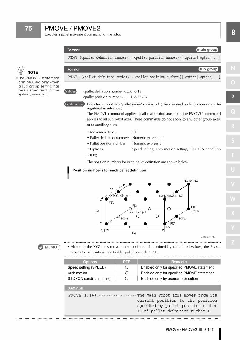
PMOVE / PMOVE2 8-141
88
N
O
P
Q
R
S
T
U
V
W
X
Y
Z
75 PMOVE / PMOVE2Executes a pallet movement command for the robot
Format main group
PMOVE (<pallet definition number> , <pallet position number>)[,option[,option]...]
Format sub group
PMOVE2 (<pallet definition number> , <pallet position number>)[,option[,option]...]
Values <pallet definition number>.....0 to 19
<pallet position number> .......1 to 32767
Explanation Executes a robot axis "pallet move" command. (The specified pallet numbers must be registered in advance.)
The PMOVE command applies to all main robot axes, and the PMOVE2 command
applies to all sub robot axes. These commands do not apply to any other group axes,
or to auxiliary axes.
•Movement type: PTP
•Palletdefinitionnumber: Numericexpression
•Palletpositionnumber: Numericexpression
•Options: Speed setting, arch motion setting, STOPON condition
setting
The position numbers for each pallet definition are shown below.
NX*NY*(NZ-1)+1 NX*NY*(NZ-1)+NZ
Position numbers for each pallet definition
P[5]
1 2 NX
NX*2NX+1
NX*(NY-1)+1 NX*NY
NX*NY*NZ
...
P[3] P[4]
P[2]
P[1]
NZ
NX
NY
NX*NY*(NZ-1)+1 NX*NY*(NZ-1)+NZ
33816-R7-00
•Although the XYZ axes move to the positions determined by calculated values, the R-axis
moves to the position specified by pallet point data P[1].
Options PTP Remarks
Speed setting (SPEED) Enabled only for specified PMOVE statement
Arch motion Enabled only for specified PMOVE statement
STOPON condition setting Enabled only by program execution
SAMPLE
PMOVE(1,16) ・・・・・・・・・・・・・・・・・・・・・・ The main robot axis moves from its current position to the position specified by pallet position number 16 of pallet definition number 1.
n NOTE
The PMOVE2 statement •can be used only when a sub group setting has been specif ied in the system generation.
MEMO

8-142 Chapter 8 Robot Language Lists
88
N
O
P
Q
R
S
T
U
V
W
X
Y
Z
75 PMOVE / PMOVE2
Movement type
PTP (point-to-point) movement ●
PTP movement begins after positioning of all movement axes is complete (within the tolerance
range), and the command terminates when the movement axes enter the OUT position range.
Although the movement axes reach their target positions simultaneously, their paths are not
guaranteed.
Caution regarding commands which follow the PMOVE / PMOVE2 command: ●
If the next command following the PMOVE / PMOVE2 command is an executable command
such as a signal output command, that next command will start when the movement axis enters
the OUT position range. In other words, that next command starts before the axis arrives within
the target position OUT position range.
Example:
Signal output (DO, etc.) Signal is output when axis enters within OUT position range.
DELAYDELAY command is executed and standby starts, when axis enters the OUT position range.
HALTProgram stops and is reset when axis enters the OUT position range. Therefore, axis movement also stops.
HOLDProgram temporarily stops when axis enters the OUT position range. Therefore, axis movement also stops.
WAIT WAIT command is executed when axis enters the OUT position range.
The WAIT ARM / WAIT ARM2 statements are used to execute the next command after the axis
enters the tolerance range.
P1
PMOVE command
DO(20) turns ON
PMOVE(0,1)WAIT ARMDO(20)=1
DO(20) turns ON
PMOVE(0,1)DO(20)=1
Tolerance
Target position
OUT position
HOLD execution (program temporarily stops)
PMOVE(0,1)WAIT ARMHOLD
PMOVE(0,1)HOLD
ToleranceOUT position
Target position
HOLD execution (program temporarily stops)
33827-R7-00

PMOVE / PMOVE2 8-143
88
N
O
P
Q
R
S
T
U
V
W
X
Y
Z
75 PMOVE / PMOVE2
Option types
Speed setting ● PTP
Format
1. SPEED = <expression> 2. S = <expression>
Values <expression>..........................1 to 100 (units: %)
Explanation Specifies the program speed in an <expression>. The movement speed is the
automatic movement speed multiplied by the program movement speed.
This option is enabled only for the specified PMOVE / PMOVE2 statement.
SAMPLE
PMOVE(1,3),S=10 ・・・・・・・・・・・・・ Movement occurs at 10% of the program speed, from the current position to the position specified by pallet position number 3 of pallet definition number 1.
● Arch motion setting PTP
Format
x = <expression>[, x = <expression>...]
Values x ............................................Specifies the Z,R,A,B axis.
<expression>..........................An integer value is processed in "pulse" units.
A real number (with decimal point) is process in "mm/
deg" units.
Explanation 1. The "x" specified axis begins moving toward the position specified by the
<expression>.
2. When the "x" specified axis enters the arch position range, all other axes move
toward the target position.
3. When all axes other than the "x" specified axis enter the arch position range,
and the "x" specified axis enters the tolerance range of the position specified by
the <expression>, the "x" specified axis then moves to the target position.
4. The command ends when all axis enter the OUT position range.
SAMPLE
PMOVE(1,A),Z=0 ・・・・・・・・The Z-axis first moves from the current position to the "0 pulse" position. Then the other axes move to the position specified by pallet position number A of pallet definition number 1. Finally the Z-axis moves to the position specified by pallet position number A.
n NOTE
This option specifies only •t h e m a x i m u m s p e e d and does not guarantee m o v e m e n t a t t h e specified speed.

8-144 Chapter 8 Robot Language Lists
88
N
O
P
Q
R
S
T
U
V
W
X
Y
Z
75 PMOVE / PMOVE2
SAMPLE:PMOVE Z
Target position: P1Current position
1. Z-axis movement 3. Z-axis movement
2. Other axes movement
Z-axis arch position range
Other axes' arch position range
Z=0
33817-R7-00
● STOPON condition setting PTP
Format
STOPON <conditional expression>
Explanation Stops movement when the conditions specified by the conditional expression are
met. Because this is a deceleration type stop, there will be some movement (during
deceleration) after the conditions are met.
If the conditions are already met before movement begins, no movement occurs,
and the command is terminated.
This option is only possible by program execution.
SAMPLE
PMOVE(A,16),STOPON DI(20)=1 ・・・・・・・・・・・・・・ Moves from the current position to the position
specified by pallet position number 16 of pallet definition number A, then decelerates and stops when the condition "DI(20) = 1" is met.
•When the conditional expression used to designate the STOPON condition is a numeric
expression, the conditions for determining a TRUE or FALSE status can be changed at the
controller's "TRUE conditions" in the "Other parameters" mode. These conditions apply to all
the IF, WHILE, WAIT, STOPON, etc., conditional expressions. For details, refer to the controller
user's manual.
1) -1 (default setting) An expression value of "-1" indicates a TRUE status, and "0" indicates
a FALSE status.
A "6.35 Incorrect condition expression" error occurs if the expression
value is other than "-1" or "0".
2) not 0 Any expression value other than "0" indicates a TRUE status, and "0"
indicates a FALSE status.
MEMO
n NOTE
This parameter is only •available in the following software versions:
RCX14x Ver. 8.63 onwards
RCX22x Ver. 9.08 onwards
O n e a r l i e r v e r s i o n •controllers, -1 is "true" and a value other than -1 is "false" (not changeable).

Pn 8-145
88
N
O
P
Q
R
S
T
U
V
W
X
Y
Z
76 PnDefines points within a program
Format
Pn = x y z r a b [f ] [f 1] [f 2]
Values n ............................................Point number: 0 to 9999.
x, y, z, r, a, b ..........................Point data: the range varies according to the format.
f .............................................Hand system flag: 1 or 2 (for SCARA robots only).
f1 ........................................... X-arm rotation information : -1, 0, 1 (YK500TW model only).
f2 ........................................... Y-arm rotation information : -1, 0, 1 (YK500TW model only).
Explanation Defines the point data.
1. "n" indicates the point number.
2. Input data for "x" to "b" must be separated with a space (blank).
3. If all input data for "x" to "b" are integers (no decimal points), the movement units
are viewed as "pulses". "x" through "b" then correspond to axis 1 through axis 6.
4. If there is even 1 real number (with decimal point) in the input data for "x"
through "b", the movement units are recognized as "mm". In this case, "x" to "z"
correspond to the x, y and z coordinates of a Cartesian coordinate system, while
"r" to "b" correspond to axes 4 to 6.
5. The input data ranges are as follows:
For "pulse" units: -6,144,000 to 6,144,000 range
For "mm" units: -99,999.99 to 99,999.99 range
Hand system flags can be specified for SCARA robots when specifying point definition
data in "mm" units.
To specify an extended hand system flag for SCARA robots, set either 1 or 2 at "f". If a
number other than 1 or 2 is set, or if no number is designated, 0 will be set, indicating
that there is no hand system flag.
1: Indicates a right-handed system point setting.
2: Indicates a left-handed system point setting.
X-arm and Y-arm rotation information (*1) can be specified on YK500TW where point
data is defined in "mm" units.
To set extended X-arm and Y-arm rotation information at the YK500TW model robot,
a "-1", "0", or "1" value must be specified at f1 and f2. Any other value, or no X-arm
and Y-arm rotation information at all, will be processed as "0".
0: Indicates arm rotation information where "0" has been specified.
1: Indicates arm rotation information where "1" has been specified.
-1: Indicates arm rotation information where "-1" has been specified.
*1: For details regarding the X-arm and Y-arm rotation information, refer to
Chapter 4 "3. Point data format".
n NOTE
In controllers with software •versions earlier than 8.28, only point numbers 0 to 4000 can be specified by point variables.
n NOTE
I f b o t h i n t e g e r s a n d •real numbers are used together (m ixed) , a l l coordinate values wi l l be handled in "mm/deg" units.
Hand system flags are •o n l y a v a i l a b l e f r o m sof tware vers ion 8 .08 onwards.
X-arm and Y-arm rotation •i n f o r m a t i o n i s o n l y avai lable in sof tware Ver.10.66 onwards.

8-146 Chapter 8 Robot Language Lists
88
N
O
P
Q
R
S
T
U
V
W
X
Y
Z
76 Pn
SAMPLE
P1 = 0 0 0 0 0 0P2 = 100.00 200.00 50.00 0.00 0.00 0.00 P3 = 10.00 0.00 0.00 0.00 0.00 0.00 P10= P2 FOR A=10 TO 15 P[A+1]=P[A]+P3 NEXT A FOR A=10 TO 16 MOVE P,P1,P[A] NEXT A HALT
Related commands Point assignment statement (LET)
n NOTE
A l l i n p u t v a l u e s a r e •handled as constants.
I f c o n t r o l l e r p o w e r •i s t u r n e d o f f d u r i n g execut ion o f a po in t definition statement, a memory- re lated er ror such as "9.2: Point check-sum error" may occur.

PPNT 8-147
88
N
O
P
Q
R
S
T
U
V
W
X
Y
Z
77 PPNTCreates pallet point data
Format
PPNT(pallet definition number,pallet position number)
Explanation Creates the point data specified by the pallet definition number and the pallet position
number.
SAMPLE
P10=PPNT(1,24) ・・・・・・・・・・・・・・・・・・ Creates, at P10, the point data specified by pallet position number 24 of pallet definition number 1.
Related commands PDEF, PMOVE, PMOVE2

8-148 Chapter 8 Robot Language Lists
88
N
O
P
Q
R
S
T
U
V
W
X
Y
Z
78 PRINTDisplays the specified expression value at the programming box
Format
PRINT [<expression][ , <expression>...][ , ] ; ;
Values <expression>..........................character string, numeric value, variable.
Explanation Displays a specified variable on the programming box screen.
Output definitions are as follows:
1. If numbers or character strings are specified in an <expression>, they display as
they are. If variables or arrays are specified, the values assigned to the specified
variables or arrays display.
2 If no <expression> is specified, only a line-feed occurs.
3. If the data length exceeds the screen width, a line-feed occurs, and the data wraps
to the next line.
4. If a comma ( , ) is used as a display delimiter, a space (blank) is inserted between
the displayed items.
5. If a semicolon ( ; ) is used as a display delimiter, the displayed items appear in
succession without being separated.
6. If the data ends with a delimiter, the next PRINT statement is executed without a
line-feed. When not ended with a display delimiter, a line-feed occurs.
•DatacommunicationtotheprogrammingboxscreenoccursinorderforthePRINTstatement
to be displayed there. Therefore, program execution may be delayed when several PRINT
statements are executed consecutively.
SAMPLE
PRINT A Displays the value of variable A.PRINT "A1 =";A1 ・・・・・・・・・・・・・・ Displays the value of variable
A1 after "A1 =".PRINT "B(0),B(1) = ";B(0);",";B(1) PRINT P100 ・・・・・・・・・・・・・・・・・・・・・・・・ Displays the P100 value.
Related commands INPUT

8
RADDEG 8-149
8
N
O
P
Q
R
S
T
U
V
W
X
Y
Z
79 RADDEGPerforms a unit conversion (radians → degrees)
Format
RADDEG(<expression>)
Values <expression>..........................Angle (units: radians)
Explanation Converts the <expression> value to degrees.
SAMPLE
LOCR(P0)=RADDEG(ATN(B)) ・・・ Converts the variable B arctangent value to degrees, and assigns it to R-data of P0.
Related commands ATN, COS, DEGRAD, SIN, TAN
8
8-150 Chapter 8 Robot Language Lists
8
N
O
P
Q
R
S
T
U
V
W
X
Y
Z
80 REMInserts a comment
Format
1. REM <character string>2. ' <character string>
Explanation All characters which follow REM or an apostrophe (') are handled as a comment. This
comment statement is used only to insert comments in the program, and it does not
execute any command. The apostrophe (') can be entered at any point in the line.
SAMPLE
REM *** MAIN PROGRAM *** ’*** SUBROUTINE *** HALT ’HALT COMMAND

8
RESET 8-151
8
N
O
P
Q
R
S
T
U
V
W
X
Y
Z
81 RESETTurns OFF the bits of specified ports, or clears variables
Format 1
RESET DOm([b,・・・,b]) DO(mb,・・・,mb) MOm([b,・・・,b]) MO(mb,・・・,mb) TO0([b,・・・,b]) TO(0b,・・・,0b) LO0([b,・・・,b]) LO(0b,・・・,0b) SOm([b,・・・,b]) SO(mb,・・・,mb)
Format 2
RESET TCOUNTER
Values m: port number ......................2 to 7, 10 to 17, 20 to 27
b: bit definition ......................0 to 7
Explanation Format 1: Turns the bits of specified ports OFF.
Format 2: Clears the 10ms counter variables (10ms counter variables are used to
measure the time in 10ms units).
If multiple bits are specified, they are expressed from the left in descending order (large
to small).
If the [b,…,b] data is omitted, all 8 bits are processed.
SAMPLE
RESET DO2() ・・・・・・・・・・・・・・・・・・・・・ Turns OFF DO(27 to 20). RESET DO2(6,5,1) ・・・・・・・・・・・・ Turns OFF DO(26, 25, 21). RESET (37,35,27,20) ・・・・・・・・・ Turns OFF DO(37, 35, 27, 20). RESET TCOUNTER ・・・・・・・・・・・・・・・・ Clears the 10ms counter
variables.
Related commands SET, DO, MO, SO, TO, LO
c CAUTION
Output to ports "0" and "1" •is not allowed at DO, MO, and SO.
参照REFERENCE
For details regarding bit •definitions, see Chapter 3 "10 Bit Settings".

8
8-152 Chapter 8 Robot Language Lists
8
N
O
P
Q
R
S
T
U
V
W
X
Y
Z
82 RESTARTRestarts another task during a temporary stop
Format
RESTART Tn
Values n: Task number ......................2 to 8
Explanation Restarts another task that has been temporarily stopped (SUSPEND status).
RESTART cannot be executed for Task 1.
SAMPLE
START *SUBTASK,T2 FLAG=1*L0: IF FLAG=1 AND DI2(0)=1 THEN SUSPEND T2 FLAG=2 WAIT DI2(0)=0 ENDIF IF FLAG=2 AND DI2(0)=1 THEN RESTART T2 FLAG=1 WAIT DI2(1)=0 ENDIF MOVE P,P0 MOVE P,P1 GOTO *L0 HALT’SUBTASK ROUTINE*SUBTASK: DO2(0)=1 DELAY 1000 DO2(0)=0 DELAY 1000 GOTO *SUBTASK EXIT TASK
Related commands CUT, EXIT TASK, START, SUSPEND
Reference For details, refer to the "Multi-Task" item.

8
RESUME 8-153
8
N
O
P
Q
R
S
T
U
V
W
X
Y
Z
83 RESUMEResumes program execution after error recovery processing
Format
1. RESUME NEXT2. RESUME <label>
Explanation Resumes program execution after recovery from an error.
Depending on its location, a program can be resumed in the following 3 ways:
1. RESUME The program resumes from the command which caused the
error.
2. RESUME NEXT The program resumes from the next command after the
command which caused the error.
3. RESUME <label> The program resumes from the command specified by the
<label>.
•The RESUME statement can also be executed in an error processing routine.
•"Errorrecoveryprocessingisnotpossibleforseriouserrorssuchas"17.4:Overload",etc.
Related commands ON ERROR GOTO
参照REFERENCE
For details, see Chapter 8 •"60 ON ERROR GOTO".
MEMO

8
8-154 Chapter 8 Robot Language Lists
8
N
O
P
Q
R
S
T
U
V
W
X
Y
Z
84 RETURNProcessing which was branched by GOSUB, is returned to the next line after GOSUB
Format
GOSUB <label> * GOSUB can also be expressed as "GO SUB". : <label>: :
RETURN
Explanation Ends the subroutine and returns to the next line after the jump source GOSUB
statement.
All subroutines (jump destinations) specified by a GOSUB statement must end with a
RETURN statement. Using the GOTO statement, etc., to jump from a subroutine will
cause an error such as the "5.12: Stack overflow", etc.
SAMPLE
*ST: MOVE P,P0 GOSUB *CLOSEHAND MOVE P,P1 GOSUB *OPENHAND GOTO *ST HALT ’SUB ROUTINE *CLOSEHAND: DO(20) = 1 RETURN *OPENHAND: DO(20) = 0 RETURN
Related commands GOSUB
8
RIGHT$ 8-155
8
N
O
P
Q
R
S
T
U
V
W
X
Y
Z
85 RIGHT$Extracts a character string from the right end of another character string
Format
RIGHT$(<character string expression>,<expression>)
Values <expression>..........................0 to 75
Explanation This function extracts a character string with the digits specified by the <expression>
from the right end of the character string specified by <character string expression>.
The <expression> value must be between 0 and 75, otherwise an error will occur.
If the <expression> value is 0, then RIGHT$ will be a null string (empty character
string).
If the <expression> value has more characters than the <character string expression>,
RIGHT$ will become the same as the <character string expression>.
SAMPLE
B$=RIGHT$(A$,4) ・・・・・・・・・・・・・・・・ 4 characters from the right end of A$ are assigned to B$.
Related commands LEFT$, MID$

8
8-156 Chapter 8 Robot Language Lists
8
N
O
P
Q
R
S
T
U
V
W
X
Y
Z
86 RIGHTY / RIGHTY2Sets the SCARA robot hand system to "Right"
Format main group
RIGHTY
Format sub group
RIGHTY2
Explanation This statement specifies right-handed movement to a point specified in Cartesian
coordinates. This statement only selects the hand system, and does not move the
robot. If executed while the robot arm is moving, execution waits until movement is
complete (positioned within tolerance range).
This command is only valid for SCARA robots.
SAMPLE
RIGHTY ・・・・・・・・・・・・・・・・・・・・・・・・・・ Specifies a robot "right-handed system" setting (see Fig.1 below).
MOVE P,P1 LEFTY ・・・・・・・・・・・・・・・・・・・・・・・・・・ Specifies a robot "left-handed
system" setting (see Fig.2 below).
MOVE P,P1 RIGHTY HALT
SAMPLE:LEFTY/RIGHTY
P1
(1)(2)
Left-handed system Right-handed system
SCARA robot
33818-R7-00
Related commands LEFTY, LEFTY2
n NOTE
RIGHT2 can be used only •if a "sub group" setting has been specified in the system generation.

8
RSHIFT 8-157
8
N
O
P
Q
R
S
T
U
V
W
X
Y
Z
87 RSHIFTShifts a bit value to the right
Format
RSHIFT(<expression 1>,<expression 2>)
Explanation Shifts the <expression 1> bit value to the right by the amount of <expression 2>.
Spaces left blank by the shift are filled with zeros (0).
SAMPLE
A=RSHIFT(&B10111011,2) ・・・・・・ The 2 - bit-right-shifted &B10111011 value (&B00101110) is assigned to A.
Related commands LSHIFT

8
8-158 Chapter 8 Robot Language Lists
8
N
O
P
Q
R
S
T
U
V
W
X
Y
Z
88 SnDefines the shift coordinates in the program
Format
Sn = x y z r
Values n ............................................0 to 9
x, y, z, r ..................................-99,999.99 to 99,999.99
Explanation Defines shift coordinate values in order to shift the coordinates for robot movement.
Only "mm" units can be used for these coordinate values ("pulse" units cannot be
used).
1. "n" indicates the shift number.
2. The "x" to "r" input data must be separated with spaces (blanks).
3. The "x" to "r" input data is recognized as "mm" unit data.
4. "x" to "z" correspond to the Cartesian coordinate system's x, y, z coordinate shift
values, and "r" corresponds to the xy coordinates' rotational shift values.
SAMPLE
S0 = 0.00 0.00 0.00 0.00 S1 = 100.00 200.00 50.00 90.00 P3 = 100.00 0.00 0.00 0.00 0.00 0.00 SHIFT S0 MOVE P,P3 SHIFT S1 MOVE P,P3 HALT
Related commands Shift assignment statement, SHIFT, SHIFT2
n NOTE
A l l i n p u t v a l u e s a r e •handled as constants.
If the controller power •i s t u r n e d o f f d u r i n g e x e c u t i o n o f a s h i f t coord inate def in i t ion statement, a memory-related error such as "9.6: Shift check-sum error" may occur.

8
SELECT CASE 8-159
8
N
O
P
Q
R
S
T
U
V
W
X
Y
Z
89 SELECT CASEExecutes the specified command block in accordance with the <expression> value
Format
SELECT [CASE] <expression> CASE <expression list 1> [command block 1] [CASE <expression list 2> [command block 2]] : [CASE ELSE [command block n]] END SELECT
Explanation These statements execute multiple command blocks in accordance with the
<expression> value. The setting method is as follows.
1. The <expression list> following CASE statement comprises multiple numerical
expressions and character expressions separated from each other by a comma ( , ).
2. If the <expression> value matches one of expressions contained in the
<expression list>, the specified command block is executed. After executing the
command block, the program jumps to the next command which follows the
END SELECT statement.
3. If the <expression> value does not match any of the expressions contained in the
<expression list>, the command block indicated after the CASE ELSE statement
is executed. After executing the command block, the program jumps to the next
command which follows the END SELECT statement.
4. If the <expression> value does not match any of the expressions contained in
<expression list> and no CASE ELSE statement exists, the program jumps to the
next command following the END SELECT statement.
SAMPLE
WHILE -1 SELECT CASE DI3() CASE 1,2,3 CALL *EXEC(1,10) CASE 4,5,6,7,8,9,10 CALL *EXEC(11,20) CASE ELSE CALL *EXEC(21,30) END SELECT WEND HALT

8
8-160 Chapter 8 Robot Language Lists
8
N
O
P
Q
R
S
T
U
V
W
X
Y
Z
90 SENDSends <read file> data to the <write file>
Format
SEND <read file> TO <write file>
Explanation Sends <read file> data to the <write file>.
An entire DO, MO, TO, LO, SO, or SOW port (DO(), MO(), etc.), cannot be specified
as a write file.
Moreover, some individual files (DOn(), MOn(), etc.) cannot be specified as a write
file. For details, refer to Chapter 11 "Data file description".
Writing to read-only files (indicated by a "×" in the "WRITE" column of the table
shown below) is not permitted.
Even if the READ and WRITE files are specified correctly, it may not be possible to
execute them if there is a data format mismatch between the files.
n NOTE
Examples of erroneous •writing to a read-only file:
SEND CMU TO DIR
SEND PNT TO SI()
Examples of data format •mismatches:
SEND PGM TO PNT
SEND SI() TO SFT
n NOTE
I n d i v i d u a l " p o i n t •comment" f i les (PCn) are on ly ava i lab le in the following software versions.
RCX14x Ver. 8.64 onwards
RCX22x Ver. 9.11 onwards
User All files ALL
Program PGM <bbbbbbbb>
Point PNT Pn
Point comment PCM PCn
Parameter PRM /cccccc/
Shift definition SFT Sn
Hand definition HND Hn
Pallet definition PLT PLn
Variable, Variable VAR ab...by
Constant Array variable ART ab...by(x)
Constant “cc...c” ×
Status Program directory DIR <<bbbbbbbb>> ×
Parameter directory DPM ×
Machine reference MRF ×
Error log LOG ×
Remaining memory size MEM ×
Device DI port DI() DIn() ×
DO port DO() DOn()
MO port MO() MOn()
TO port TO() TOn()
LO port LO() LOn()
SI port SI() SIn() ×
SO port SO() SOn()
SIW port SIW() SIWn() ×
SOW port SOW() SOWn()
RS-232C CMU
Ethernet ETH
Other File END code EOF ×
N: Number a: Alphabetic character b: Alphanumeric character or underscore (_)
c: Alphanumeric character or special symbol x: Expression (array argument) y: Variable type
: Permitted
× : Not permitted
Type File Name
Definition Format READ WRITE
All Individual File

8
SEND 8-161
8
N
O
P
Q
R
S
T
U
V
W
X
Y
Z
90 SEND
•The following cautions apply when a restart is performed after a stop occurred during execution
of the SEND statement:
1. When reading from RS-232C / Ethernet (SEND CMU TO XXX, SEND ETH TO XXX):
When the SEND statement is stopped during data reading from the reception buffer, the data
acquired up to that point is discarded.
2. When writing to RS-232C / Ethernet (SEND XXX TO CMU, SEND XXX TO ETH):
When the SEND statement is stopped during data writing to the transmission buffer, the data
is written from the beginning.
SAMPLE
SEND PGM TO CMU ・・・・・・・・・・・・・・・・ Outputs all user programs from the RS-232C port.
SEND <PRG1> TO CMU ・・・・・・・・・・・ Outputs the PRG1 program from the RS-232C port.
SEND CMU TO PNT ・・・・・・・・・・・・・・・・ Inputs a point data file from the RS-232C port.
SEND "T1" TO CMU ・・・・・・・・・・・・・・ Outputs the "T1" character string from the RS-232C port.
SEND CMU TO A$ ・・・・・・・・・・・・・・・・・ Inputs character string data to variable A$ from the RS-232C port.
Reference For details, refer to Chapter 11 "Data file description".
MEMO

8
8-162 Chapter 8 Robot Language Lists
8
N
O
P
Q
R
S
T
U
V
W
X
Y
Z
91 SERVO / SERVO2Controls the servo status
Format main group
SERVO ON [(<axis number>)] OFF FREE PWR
Format sub group
SERVO2 ON [(<axis number>)] OFF FREE PWR
Values <axis number> .......................main group: 1 to 6
sub group: 1 to 4
Explanation This statement controls the servo ON/OFF at the specified axes or all axes. When the
axes have been specified by an <axis number> setting, this statement applies only
to the specified axes within the group. If no axes have been specified by an <axis
number> setting, this statement applies to all the main and sub group axes. In this
case, motor power supply ON/OFF switching occurs simultaneously with the servo
ON/OFF operations.
•ON ...... Turns the servo ON. If no axis is specified, the motor power supply also
turns ON.
•OFF...... Turns the servo OFF and applies the dynamic brake. Axes equipped with
brakes are all locked by the brake. If no axis is specified, the motor power
supply also turns OFF.
•FREE..... Turns the servo OFF and releases the dynamic brake. The brakes are
released at all axes with brakes. If no axis is specified, the motor power
supply also turns OFF.
•PWR .... Turns only the motor power supply ON.
•This statement is executed after positioning of all axes (in the main group and sub group) is
complete (within the tolerance range).
•IndividualaxisservoscannotbeturnedONaslongasthemotorpowerisOFF.
SAMPLE
SERVO ON ・・・・・・・・・・・・・・・・・・・・・・・・・・ Turns servos ON at all axes after turning the motor power ON.
SERVO OFF ・・・・・・・・・・・・・・・・・・・・・・・・・ Turns the motor power OFF, then turns the servos at all axes OFF. Brakes are applied, and a lock status is established at axes equipped with brakes.
SERVO FREE(3) ・・・・・・・・・・・・・・・・・・・ The axis 3 (Z-axis) servo is turned OFF, and the brake is released.
n NOTE
The SERVO2 statement •can be used only when a sub group setting has been specif ied in the system generation.
c CAUTION
Keep out of the robot •movement range while the motor power is turned OFF by the SERVO OFF statement. Always check that the Emergency Stop is ON when working within the robot movement area.
MEMO

8
SET 8-163
8
N
O
P
Q
R
S
T
U
V
W
X
Y
Z
92 SETTurns the bit at the specified output port ON
Format
SET DOm([b,・・・,b]) [, <time>] DO (mb,・・・,mb) MOm([b,・・・,b]) MO (mb,・・・,mb) TO0([b,・・・,b]) TO (0b,・・・,0b) LO0([b,・・・,b]) LO (0b,・・・,0b) SOm([b,・・・,b]) SO (mb,・・・,mb)
Values m: port number ......................2 to 7, 10 to 17, 20 to 27
b: bit definition ......................0 to 7
<time> ...................................10 to 3600000 (units: ms)
Explanation Turns ON the bits of specified ports.
The pulse output time (unit: ms) is specified by the <time> value. When the specified
time elapses, the output is turned OFF, and command execution ends.
If multiple bits are specified, they are expressed from the left in descending order (large
to small).
If the [b,…,b] data is omitted, all 8 bits are processed.
If no hardware port exists, nothing is output.
SAMPLE
SET DO2() ・・・・・・・・・・・・・・・・・・・・・・・・・ Turns ON DO(27 to 20).SET DO2(6,5,1),200 ・・・・・・・・・・・・ DO(26,25,21) switches ON for
200ms.SET DO(37,35,27,20) ・・・・・・・・・・ Turns DO(37, 35, 27, 20) ON.
Related commands RESET, DO, MO, SO, TO, LO
c CAUTION
Output to ports "0" and "1" •are not allowed at DO, MO, and SO.
参照REFERENCE
For bit setting details, see •Chapter 3 "10 Bit Settings".

8
8-164 Chapter 8 Robot Language Lists
8
N
O
P
Q
R
S
T
U
V
W
X
Y
Z
93 SHAREDEnables sub-procedure referencing without passing on the variable
Format
SHARED <variable>[()][,<variable>[()]... ]
Explanation This statement allows variables declared with a program level code to be referenced
with a sub-procedure without passing on the variables as dummy arguments.
The program level variable used by the sub-procedure is specified by the <variable>
value.
A simple variable or an array variable followed by parentheses is specified. If an array
is specified, that entire array is selected.
•Normally, a <dummy argument> passes along the variable to a sub-procedure, but the SHARED
statement allows referencing to occur without passing along the variable.
•TheSHAREDstatementallowsvariablestobesharedonlybetweenaprogram level code and
sub-procedure which are within the same program level.
SAMPLE
DIM Y!(10) X!=2. 5 Y!(10)=1. 2 CALL *DISTANCE CALL *AREA HALT SUB *DISTANCE SHARED X!,Y!( ) ・・・・・・・・・・・ Variable referencing is
declared by SHARED. PRINT X!^2+Y!(10)^2 ・・・・・・ The variable is shared.END SUB SUB *AREA DIM Y!(10) PRINT X!*Y!(10) ・・・・・・・・・・・・ The variable is not shared.END SUB
Related commands SUB, END SUB
n NOTE
The program level code is •a program written outside the sub-procedure.
MEMO

8
SHIFT / SHIFT2 8-165
8
N
O
P
Q
R
S
T
U
V
W
X
Y
Z
94 SHIFT / SHIFT2Sets the shift coordinates
Format main group
SHIFT <shift variable>
Format sub group
SHIFT2 <shift variable>
Explanation Sets the shift coordinates in accordance with the shift data specified by the <shift
variable>.
•This statement is executed after axis positioning is complete (within the tolerance range).
•ThedefaultshiftsettingisS0(noshiftvalues).
SAMPLE
SHIFT S1 MOVE P,P10 SHIFT S[A] MOVE P,P20 HALT
Related commands Shift definition statement, shift assignment statement
n NOTE
The SHIFT2 statement can •be used only when a sub group setting has been specified in the system generation.
MEMO

8
8-166 Chapter 8 Robot Language Lists
8
N
O
P
Q
R
S
T
U
V
W
X
Y
Z
95 SINAcquires the sine value for a specified value
Format
SIN(<expression>)
Values <expression>..........................Angle (units: radians)
Explanation This function gives the sine value for the <expression> value.
SAMPLE
A(0)=SIN(B*2+C) ・・・・・・・・・・・・・・・・ Assigns the expression B*2+C sine value to array A (0).
A(1)=SIN(DEGRAD(30)) ・・・・・・・・ Assigns a 30.0° sine value to array A (1).
Related commands ATN, COS, DEGRAD, RADDEG, TAN

8
SO 8-167
8
N
O
P
Q
R
S
T
U
V
W
X
Y
Z
96 SOOutputs a specified value to the serial port
Format
1. [LET]SOm([b,・・・,b]) = <expression> 2. [LET]SO (mb,・・・,mb) = <expression>
Values m: port number ......................2 to 7, 10 to 17, 20 to 27
b: bit definition ......................0 to 7
Explanation Outputs a specified value to the SO port.
Only the <value> data's integer-converted lower bits corresponding to the bits
defined at the left side can be output.
If multiple bits are specified, they are expressed from the left in descending order (large
to small).
If the [b,…,b] data is omitted, all 8 bits are processed.
If no hardware port exists, nothing is output.
SAMPLE
SO2()=&B10111000 ・・・・・・・・・・・・・・ SO (27, 25, 24, 23) are turned ON, and SO (26, 22, 21, 20) are turned OFF.
SO2(6,5,1)=&B010 ・・・・・・・・・・・・・ SO (25) are turned ON, and SO (26, 21) are turned OFF.
SO3()=15 ・・・・・・・・・・・・・・・・・・・・・・・・・ SO (33, 32, 31, 30) are turned ON, and SO (37, 36, 35, 34) are turned OFF.
SO(37,35,27,20)=A ・・・・・・・・・・・・・・ The lower 4 bits of integer-converted variable A are output to SO (37, 35, 27, 20).
Related commands RESET, SET
c CAUTION
Outputs to SO0() and •SO1() are not possible.
参照REFERENCE
For bit setting details, see •Chapter 3 "10 Bit Settings".

8
8-168 Chapter 8 Robot Language Lists
8
N
O
P
Q
R
S
T
U
V
W
X
Y
Z
97 SPEED / SPEED2Changes the program movement speed
Format main group
SPEED <expression>
Format sub group
SPEED2 <expression>
Values <expression>..........................1 to 100 (units: %)
Explanation Changes the program movement speed to the speed indicated by the <expression>.
This speed change applies to all the robot axes and auxiliary axes.
The operation speed is determined by multiplying the automatic movement speed
(specified from the programming box and by the ASPEED/ASPEED2 commands), by
the program movement speed (specified by SPEED/SPEED2 commands, etc.).
Operation speed = automatic movement speed x program movement speed.
Example:
Automatic movement speed ... 80%
Program movement speed ... 50%
Movement speed = 40% (80% × 50%)
SAMPLE
ASPEED 100 SPEED 70 MOVE P,P0 ・・・・・・・・・・・・・・・・・・・・・・・・・ Moves from current position to
P0 at a speed of 70% (=100 * 70).SPEED 50 MOVE P, P1 ・・・・・・・・・・・・・・・・・・・・・・・・ Moves from current position to
P1 at a speed of 50% (=100 * 50).MOVE P,P2, S=10 ・・・・・・・・・・・・・・・・ Moves from current position to
P2 at a speed of 10% (=100 * 10).HALT
Related commands ASPEED, ASPEED2
n NOTE
SPEED2 can be used only •if a "sub group" setting has been specified in the system generation.
n NOTE
Automatic movement •speed
S p e c i f i e d b y p r o g r a m m i n g b o x o p e r a t i o n o r b y t h e A S P E E D / A S P E E D 2 commands.
P r o g r a m m o v e m e n t •speed
S p e c i f i e d b y S P E E D /SPEED2 commands or MOVE/MOVE2, DRIVE/DRIVE2 speed options.

8
START 8-169
8
N
O
P
Q
R
S
T
U
V
W
X
Y
Z
98 STARTStarts a new task
Format
START <label>, Tn[, p]
Values n: Task number ......................2 to 8
p: Task priority ranking ..........17 to 47
Explanation Starts task "n" specified by the <label> with the "p" priority ranking.
If a priority ranking is not specified, "32" is adopted as the priority ranking for this
task.
The smaller the priority number, the higher the priority (high priority: 17 ↔ low
priority: 47).
When a READY status occurs at a task with higher priority, all tasks with lower
priority also remain in a READY status.
SAMPLE
START *SUBTASK,T2,33 *ST: MOVE P,P0,P1 GOTO *ST HALT ‘SUBTASK ROUTINE *SUBTASK: P100 = WHERE IF LOCZ(P100) > 10000 THEN DO(20) = 1 ELSE DO(20) = 0 ENDIF GOTO *SUBTASK EXIT TASK
Related commands CUT, EXIT TASK, RESTART, SUSPEND, CHGPRI
8
8-170 Chapter 8 Robot Language Lists
8
N
O
P
Q
R
S
T
U
V
W
X
Y
Z
99 STR$Converts a numeric value to a character string
Format
STR$(<expression>)
Explanation Converts the value specified by the <expression> to a character string. The
<expression> specifies an integer or real number value.
SAMPLE
B$=STR$(10.01)
Related commands VAL

8
SQR 8-171
8
N
O
P
Q
R
S
T
U
V
W
X
Y
Z
100 SQRAcquires the square root of a specified value
Format
SQR(<expression>)
Values <expression>..........................0 or positive number.
Explanation Gives the square root of the <expression> value. An error occurs if the <expression>
value is a negative number.
SAMPLE
A=SQR(X^2+Y^2) ・・・・・・・・・・・・・・・・・・ The square root of X^2+Y^2 is assigned to variable A.

8
8-172 Chapter 8 Robot Language Lists
8
N
O
P
Q
R
S
T
U
V
W
X
Y
Z
101 SUB to END SUBDefines a sub-procedure
Format
SUB <label> [(<dummy argument> [, <dummy argument> ...])] <command block>END SUB
Explanation Defines a sub-procedure.
The sub-procedure can be executed by a CALL statement. When the END SUB
statement is executed, the program jumps to the next command after the CALL
statement that was called. Definitions are as follows.
1. All variables declared within the sub-procedure are local variables, and these are
valid only within the sub-procedure. Local variables are initialized each time the
sub-procedure is called up.
2. Use a SHARED statement in order to use global variables (program level).
3. Use a <dummy argument> when variables are to be passed on. If two or more
dummy arguments are used, separate them by a comma ( , ).
4. A valid <dummy argument> consists of a name of variable and an entire array
(array name followed by parentheses). An error will occur if array elements (a
<subscript> following the array name) are specified.
•Sub-procedures cannot be defined within a sub-procedure.
•TheDECLAREstatementcannotbeusedwithinasub-procedure.
•Alabelcanbedefinedwithinasub-procedure,but itcannot jump(byaGOTOorGOSUB
statement) to a label outside the sub-procedure.
•LocalvariablescannotbeusedwithPRINTandSENDstatements.
SAMPLE 1
A=1CALL *TESTPRINT AHALT’SUB ROUTINE: TESTSUB *TEST A=50 ・・・・・・・・・・・・・・・・・・・・・・・・・・ H a n d l e d a s a d i f f e r e n t
variable than the "A" shown above.
END SUB
•In the above example, the program level variable "A" is unrelated to the variable "A" within the
sub-procedure. Therefore, the value indicated in the 3rd line PRINT statement becomes "1".
MEMO
MEMO

8
to 8-173
8
N
O
P
Q
R
S
T
U
V
W
X
Y
Z
101 SUB to END SUB
SAMPLE 2
X% = 4 Y% = 5 CALL *COMPARE( REF X%, REF Y% ) PRINT X%,Y% Z% = 7 W% = 2 CALL *COMPARE( REF Z%, REF W% )PRINT Z%,W% HALT ’SUB ROUTINE: COMPARE SUB *COMPARE( A%, B% ) IF A% < B% THEN TEMP% = A% A% = B% B% = TEMP% ENDIF END SUB
•In the above example, different variables are passed along as arguments to call the sub-
procedure 2 times.
Related commands CALL, DECLARE, EXIT SUB, SHARED
MEMO

8
8-174 Chapter 8 Robot Language Lists
8
N
O
P
Q
R
S
T
U
V
W
X
Y
Z
102 SUSPENDTemporarily stops another task which is being executed
Format
SUSPEND Tn
Values n: Task number ......................2 to 8
Explanation Temporarily stops (suspends) another task which is being executed.
This statement can also be used for tasks with a higher priority ranking than this task
itself.
This statement cannot be specified for the main task (Task number 1).
SAMPLE
START *SUBTASK,T2 SUSFLG=0 *L0: MOVE P,P0 MOVE P,P1 WAIT SUSFLG=1 SUSPEND T2 SUSFLG=0 GOTO *L0 HALT ’SUBTASK ROUTINE *SUBTASK: WAIT SUSFLG=0 DO2(0)=1 DELAY 1000 DO2(0)=0 DELAY 1000 SUSFLG=1 GOTO *SUBTASK EXIT TASK
Related commands CUT, EXIT TASK, RESTART, SUSPEND

8
SWI 8-175
8
N
O
P
Q
R
S
T
U
V
W
X
Y
Z
103 SWISwitches the program being executed
Format
SWI "<"<program name>">"
Explanation This statement switches from the current program to the specified program, starting
from the first line after compiling is completed.
Although the output variable status is not changed when the program is switched, the
dynamic variables and array variables are cleared. Operation stops if an error occurs
during compiling. The program name to be switched to must be enclosed in angular
brackets (< >).
This command can be executed only in Task 1 (main task).
•If the program specified as the switching target does not exist, message "3.3: Program doesn't
exist" (code: &H0303) displays and operation stops.
•ExecutionofaSWIstatementisalwaysaccompaniedbycompiling,andthetimerequiredfor
this compiling depends on the size of the switching target program.
•Ifanerroroccursduringcompiling,anerrormessagelinedisplaysandtheprogramstops.
•TheSWIstatementcanonlybeexecutedwithin task1 (main task). Ifusedwithin tasks2
through 8, the message "6.1: Illegal command" displays and operation stops.
•TheSTOPkeyisdisabledduringcompiling.
SAMPLE
SWI <ABC> ・・・・・・・・・・・・・・・・・・・・・・・・・ Switches the execution program to "ABC".
MEMO

8
8-176 Chapter 8 Robot Language Lists
8
N
O
P
Q
R
S
T
U
V
W
X
Y
Z
104 TANAcquires the tangent value for a specified value
Format
TAN(<expression>)
Values <expression>..........................Angle (units: radians)
Explanation Gives a tangent value for the <expression> value. An error will occur if the
<expression> value is a negative number.
SAMPLE
A(0)=B-TAN(C) ・・・・・・・・・・・・・・・・・・・ The difference between the tangent values of variable B and variable C is assigned to array A (0).
A(1)=TAN(DEGRAD(20)) ・・・・・・・・ The 20.0 ° tangent value is assigned to array A (1).
Related commands ATN, COS, DEGRAD, RADDEG, SIN

8
TCOUNTER 8-177
8
N
O
P
Q
R
S
T
U
V
W
X
Y
Z
105 TCOUNTERTimer & counter
Format
TCOUNTER
Explanation Outputs count-up values at 10ms intervals starting from the point when the
TCOUNTER variable is reset (counter variable value 1 = 10ms).
After counting up to 65,535, the count is reset to 0.
SAMPLE
MOVE P,P0WAIT ARMRESET TCOUNTERMOVE P,P1WAIT ARMA = TCOUNTERPRINT TCOUNTER ・・・・・・・・・・・・・・・・・ Displays the P0 to P1 movement
time at the programming box until movement enters the tolerance range.
Related commands RESET
8
8-178 Chapter 8 Robot Language Lists
8
N
O
P
Q
R
S
T
U
V
W
X
Y
Z
106 TIME$Acquires the current time
Format
TIME$
Explanation Acquires the current time in an hh:mm:ss format character string. "hh" is the hour,
"mm" is the minutes, and "ss" is the seconds. The clock can be set in the SYSTEM
mode's initial processing.
SAMPLE
A$=TIME$PRINT TIME$
Related commands DATE$, TIMER

8
TIMER 8-179
8
N
O
P
Q
R
S
T
U
V
W
X
Y
Z
107 TIMERAcquires the current time
Format
TIMER
Functions Acquires the current time in seconds, counting from 12:00 midnight. This function is
used to measure a program's run time, etc.
The clock can be set in the SYSTEM mode's initial processing.
SAMPLE
A%=TIMERFOR B=1 TO 10MOVE P,P0MOVE P,P1NEXTA%=TIMER-A%PRINT A%/60;":";A% MOD 60HALT
Related commands TIME$
c CAUTION
The time indicated by •the internal clock may differ somewhat from the actual time.
8
8-180 Chapter 8 Robot Language Lists
8
N
O
P
Q
R
S
T
U
V
W
X
Y
Z
108 TOOutputs a specified value to the TO port
Format
1. [LET]TO0([b,・・・,b]) = <expression> 2. [LET]TO (0b,・・・,0b) = <expression>
Values b: bit definition ......................0 to 7
Explanation Outputs the specified value to the TO port. The output value is the expression's
integer-converted lower bits corresponding to the bit definition specified at the left
side.
If multiple bits are specified, they are expressed from the left in descending order (large
to small).
If the [b,…,b] data is omitted, all 8 bits are processed.
The OFF/ON settings for bits which are being used in a SEQUENCE program have
priority while the SEQUENCE program is running.
SAMPLE
TO0() = &B00000110
Related commands RESET, SET

8
TOLE / TOLE2 8-181
8
N
O
P
Q
R
S
T
U
V
W
X
Y
Z
109 TOLE / TOLE2Specifies/acquires the tolerance parameter
Format main group
1. TOLE <expression> 2. TOLE (<axis number>)= <expression>
Format sub group
1. TOLE2 <expression> 2. TOLE2 (<axis number>)= <expression>
Values <axis number> .......................main group: 1 to 6
sub group: 1 to 4
<expression>.......................... Varies according to the motor which has been specified (units: pulse)
Explanation Changes the tolerance parameter to the <expression> value.
Format 1: The change is applied to all axes of each group.
Format 2: The change is applies to only the group axes specified by <axis number>.
•If an axis that is set to "no axis" in the system generation is specified, a "5.37 : Specification
mismatch" error message displays and command execution is stopped.
•This statement isexecutedafterpositioningof the specifiedaxes iscomplete (within the
tolerance range).
Functions
Format main group
TOLE(<axis 1>)
Format sub group
TOLE2(<axis 2>)
Values <axis 1> .................................main group: 1 to 6
<axis 2> .................................sub group: 1 to 4 Explanation Acquires the tolerance parameter value for the axis specified by <axis number>.
SAMPLE
’CYCLE WITH DECREASING TOLERANCEDIM TOLE(5)FOR A=200 TO 80 STEP -20 GOSUB *CHANGE_TOLE MOVE P,P0 MOVE P,P1 NEXT A C=TOLE(2) ・・・・・・・・・・・・・・・・・・・・・・・・・ The tolerance parameter of the main
group's axis 2 is assigned to variable C.HALT *CHANGE_TOLE: FOR B=1 TO 4 TOLE(B)=A NEXT B RETURN
n NOTE
TOLE2 can be used only •if a "sub group" setting has been specified in the system generation.
MEMO
n NOTE
TOLE2 can be used only •if a "sub group" setting has been specified in the system generation.

8
8-182 Chapter 8 Robot Language Lists
8
N
O
P
Q
R
S
T
U
V
W
X
Y
Z
110 TORQUE / TORQUE2Specifies/acquires the maximum torque command value which can be set for a specified axis
Format main group
TORQUE(<axis number>)= <expression>
Format sub group
TORQUE2(<axis number>)= <expression>
Values <axis number> .......................main group: 1 to 6
sub group: 1 to 4
<expression>..........................1 to 100 (units: %)
Explanation Changes the maximum torque command value for each group's axes which have
been specified by <axis number>. The new value is enabled after the next movement
command (MOVE or DRIVE statement, etc.) is executed. The torque parameter value
does not change.
The maximum torque specified by this statement remains valid until any of the
following operations occur.
•UntilanotherTORQUE/TORQUE2commandforthesameaxisisexecuted.
•UntilatorquelimitoptionisexecutedinaDRIVE/DRIVE2statementforthesame
axis.
•Untilcontrollerpoweristurnedoffandthenonagain.
•Untilparametersarechangedorinitialized.
•Untilareturn-to-originoranabsolutereset&return-to-originisperformed.
•Untiltheservoisturnedoff.
•If an axis that is set to "no axis" in the system generation is specified, a "5.37 : Specification
mismatch" error message displays and command execution is stopped.
Functions
Format main group
TORQUE(<axis 1>)
Format sub group
TORQUE2(<axis 2>)
Values <axis 1> .................................main group: 1 to 6
<axis 2> .................................sub group: 1 to 4
Explanation Acquires the torque setting value for the axis specified by <axis number>.
n NOTE
TORQUE2 can be used •on ly i f a " sub g roup" setting has been specified in the system generation.
c CAUTION
I n v e r s i o n s p r i o r t o •Ver.2.17, the maximum torque command value becomes val id at the point when it is changed (specified) by the TORQUE / TORQUE2 statement.
If the specified torque •l im i t i s too smal l , the a x i s m a y n o t m o v e . In this case, press the emergency stop button before proceeding with the operation.
I f the specif ied value •i s less than the rated torque, an error may not occur even if the robot strikes an obstacle.
MEMO

8
TORQUE / TORQUE2 8-183
8
N
O
P
Q
R
S
T
U
V
W
X
Y
Z
110 TORQUE / TORQUE2
SAMPLE
TRQTIME(3)= 2500 ・・・・・・・・・・・・・・・ Sets the torque control time-out period as 2.5 seconds for axis 3.
DRIVE(3,P1),T= (20,15) ・・・・・・ Sets the maximum torque value to 20% of the rated torque, and the torque offset to 15, then moves axis 3 from its current position to the point specified by P1 (pushing action).
IF TRQSTS(3)= 1 THEN ・・・・・・・・ Checks if a time-out has occurred. DO(21)= 1 ・・・・・・・・・・・・・・・・・・・・・ Time-out has occurred (pushing
is complete). (Result is output to DO(21) in this example.)
ELSE DO(21)= 0 ・・・・・・・・・・・・・・・・・・・・・ Time-out has not occurred.
(Reached target position but failed to complete pushing.) (Result is output to DO(21) in this example.)
ENDIFTORQUE(3)= 100 ・・・・・・・・・・・・・・・・・・ Returns the max. torque
command value to the original value (100%).
DRIVE(3,P0) ・・・・・・・・・・・・・・・・・・・・・・ Ends the torque limit and torque control, and moves to P0.
A=TORQUE(2) ・・・・・・・・・・・・・・・・・・・・・・ The torque setting value for the main group's axis 2 is assigned to variable A.
Related commands DRIVE, DRIVE2, TRQTIME, TRQTIME2, TRQSTS, TRQSTS2, CURTRQ, CURTRQ2

8
8-184 Chapter 8 Robot Language Lists
8
N
O
P
Q
R
S
T
U
V
W
X
Y
Z
111 TRQSTS / TRQSTS2Acquires the status when DRIVE statement ends
Format
1. TRQSTS (<axis 1>)2. TRQSTS2 (<axis 2>)
Values <axis 1> .................................main group: 1 to 6
<axis 2> .................................sub group: 1 to 4
Explanation Acquires the status at the completion of a "DRIVE statement with torque limit option"
that was executed for the main group axis specified by <axis number>.
0 ......The DRIVE statement was ended for a reason other than a torque limit time-out.
1 ......The DRIVE statement was ended by torque limit time-out.
•If an axis that is set to "no axis" in the system generation is specified, a "5.37 : Specification
mismatch" error message displays and command execution is stopped.
SAMPLE
DRIVE(3,P1), T=20 ・・・・・・・・・・・・・ Moves the main group's axis 3 under torque limit control.
IF TRQSTS(3)=1 THEN ・・・・・・・・・・ Ended by a time-out with the torque limit value reached.
GOTO *OKELSE ・・・・・・・・・・・・・・・・・・・・・・・・・・ Movement ended without a time-
out occurring.GOTO *NGENDIF
Related commands DRIVE, DRIVE2, TRQTIME, TRQTIME2, CURTRQ, CURTRQ2
n NOTE
T h e T R Q S T S / T R Q S T S 2 •statement is available in software version 8.45 onwards.
MEMO

8
TRQTIME / TRQTIME2 8-185
8
N
O
P
Q
R
S
T
U
V
W
X
Y
Z
112 TRQTIME / TRQTIME2Sets/acquires the time-out period for the torque limit setting option
Format main group
TRQTIME(<axis number>) = <time-out period>
Format sub group
TRQTIME2(<axis number>) = <time-out period>
Values <axis number> .......................main group: 1 to 6
sub group: 1 to 4
<time-out period> ..................1 to 10000 (units: ms)
Explanation Specifies the torque control time-out period when using the DRIVE statement's torque
limit setting option. This command specifies the time-out period (<time-out period>)
for the axis specified by <axis number>.
A DRIVE /DRIVE2 statement executed with a torque limit option ends when the axis
has reached the target position, or when the "specified toque limit reached" time has
exceeded the time-out period specified by the TRQTIME / TRQTIME2 statement.
A value is then set in the TRQSTS / TRQSTS2 function, depending on whether or not
the "specified toque limit reached" period has exceeded the time-out period specified
by the TRQTIME / TRQTIME2 statement and this command has ended.
When the controller power is turned on, the time-out period is set to 1 second
(1,000ms).
•Although the time-out period is specified in "ms" units, it actually operates in "10ms" units.
Therefore, settings are rounded upward to 10ms. For example, if the setting is a value from 1 to 9,
this becomes 10ms. However, if "0" is specified, this becomes 1 second (1000ms).
•Ifanaxis that isset to"noaxis" in thesystemgenerationisspecified,a"5.37:Specification
mismatch" error message displays and command execution is stopped.
Functions
Format main group
TRQTIME(<axis 1>)
Format sub group
TRQTIME2(<axis 2>)
Values <axis 1> .................................main group: 1 to 6
<axis 2> .................................sub group: 1 to 4
Explanation Acquires the torque limit time-out period for the axis specified by <axis number>.
The time-out period is specified in "ms" units.
n NOTE
The TRQTIME/TRQTIME2 •statement is available in software version 8.45 onwards.
TRQTIME2 can be used •on ly i f a " sub g roup" setting has been specified in the system generation.
MEMO
n NOTE
The TRQTIME/TRQTIME2 •statement is available in software version 8.45 onwards.
TRQTIME2 can be used •on ly i f a " sub g roup" setting has been specified in the system generation

8
8-186 Chapter 8 Robot Language Lists
8
N
O
P
Q
R
S
T
U
V
W
X
Y
Z
112 TRQTIME / TRQTIME2
SAMPLE
TRQTIME(3)=2500 ・・・・・・・・・・・・・・・・ Sets the torque control time-out period as 2.5 seconds for axis 3.
DRIVE(3,P1),T=(20,15) ・・・・・・・ Sets the maximum torque value to 20% of the rated torque, and the torque offset to 15, then moves axis 3 from its current position to the point specified by P1 (pushing action).
IF TRQSTS(3)=1 THEN ・・・・・・・・・・ Checks if a time-out has occurred. DO(21)=1 ・・・・・・・・・・・・・・・・・・・・・・・ Time-out has occurred (pushing
is complete). (Result is output to DO(21) in this example.)
ELSE DO(21)=0 ・・・・・・・・・・・・・・・・・・・・・・・ Time-out has not occurred.
(Reached target position but failed to complete pushing.) (Result is output to DO(21) in this example.)
ENDIFTORQUE(3)=100 ・・・・・・・・・・・・・・・・・・・ Returns the max. torque
command value to the original value (100%).
DRIVE(3,P0) ・・・・・・・・・・・・・・・・・・・・・・ Ends the torque limit and torque control, and moves to P0.
A%=TRQTIME(3) ・・・・・・・・・・・・・・・・・・・ The torque limit time-out period for the main group's axis 3 is assigned to variable A.
Related commands DRIVE, DRIVE2, TRQSTS, TRQSTS2, CURTRQ, CURTRQ2
8
VAL 8-187
8
N
O
P
Q
R
S
T
U
V
W
X
Y
Z
113 VALConverts character strings to numeric values
Format
VAL (<character string expression>)
Explanation Converts the numeric value of the character string specified in the <character string
expression> into an actual numeric value.
The value may be expressed in integer format (binary, decimal, hexadecimal), or real
number format (decimal point format, exponential format).
The VAL value becomes "0" if the first character of the character string is "+", "-", "&"
or anything other than a numeric character.
If there are non-numeric characters or spaces elsewhere in the character string, all
subsequent characters are ignored by this function.
However, for hexadecimal expressions, A to F are considered numeric characters.
SAMPLE
A=VAL("&B100001")

8
8-188 Chapter 8 Robot Language Lists
8
N
O
P
Q
R
S
T
U
V
W
X
Y
Z
114 WAITWaits until the conditions of the DI/DO conditional expression are met
Format
WAIT <conditional expression> [,<expression>]
Values <expression>..........................10 to 3600000 (units: ms)
Meaning Establishes a "wait" status until the condition specified by the <conditional
expression> is met. Specify the time-out period (unit: ms) in the <expression>.
If a time-out period has been specified, this command terminates if the time-out
period elapses before the WAIT condition is met.
The minimum wait time is 10 ms.
•When the conditional expression is a numeric expression, the conditions for determining
a TRUE or FALSE status can be changed at the controller's "TRUE conditions" in the "Other
parameters" mode. These conditions apply to all the IF, WHILE, WAIT, STOPON, etc.,
conditional expressions. For details, refer to the controller's user manual.
1) -1 (default setting) An expression value of "-1" indicates a TRUE status, and "0" indicates
a FALSE status. A "6.35: Incorrect condition expression" error occurs if
the expression value is other than "-1" or "0".
2) not 0 Any expression value other than "0" indicates a TRUE status, and "0"
indicates a FALSE status.
SAMPLE
WAIT A=10 ・・・・・・・・・・・・・・・・・・・・・・・・・ A wait status continues until variable A becomes 10.
WAIT DI2( )=&B01010110 ・・・・・・ Waits until DI(21),(22),(24),(26) a r e t u r n e d o n , a n d DI(20),(23),(25),(27) is turned off.
WAIT DI2(4,3,2)=&B101 ・・・・・・・ Waits until DI(22) and DI(24) are turned on, and DI(23) is turned off.
WAIT DI(31)=1 OR DO(21)=1 A wait status continues until either DI (31) or DO(21) turns ON.
WAIT DI(20)=1,1000 ・・・・・・・・・・・・ A wait status continues until DI(20) turns ON. If DI(20) fails to turn ON within 1 second, the command is terminated.
Related commands DRIVE, DRIVE2, DRIVEI, DRIVEI2, MOVE, MOVE2, MOVEI, MOVEI2
MEMO
n NOTE
This parameter is only •available in the following software versions:
RCX14x Ver. 8.63 onwards
RCX22x Ver. 9.08 onwards
O n e a r l i e r v e r s i o n •controllers, -1 is "true" and a value other than -1 is "false" (not changeable).
8
WAIT ARM / WAIT ARM2 8-189
8
N
O
P
Q
R
S
T
U
V
W
X
Y
Z
115 WAIT ARM / WAIT ARM2Waits until the robot axis operation is completed
Format main group
WAIT ARM [(<axis number>)]
Format sub group
WAIT ARM2 [(<axis number>)]
Values <axis number> .......................main group: 1 to 6
sub group: 1 to 4
Explanation Establishes a "wait" status until robot axis movement is completed (within the
positioning tolerance range).
If a specific axis in a group has been specified by <axis number>, this command will
apply only to that axis. If there is no <axis number> setting, this command applies to
all the group axes.
SAMPLE
WAIT ARM ・・・・・・・・・・・・・・・・・・・・・・・・・・ Waits for main robot movement completion.
WAIT ARM2(2) ・・・・・・・・・・・・・・・・・・・・・ Waits for sub robot axis 2 movement completion.
Related commands DRIVE, DRIVE2, DRIVEI, DRIVEI2, MOVE, MOVE2, MOVEI, MOVEI2
n NOTE
WAIT ARM2 can be used •on ly i f a " sub g roup" setting has been specified in the system generation.

8
8-190 Chapter 8 Robot Language Lists
8
N
O
P
Q
R
S
T
U
V
W
X
Y
Z
116 WEIGHT/WEIGHT2Specifies/acquires the tip weight parameter
Format main group
WEIGHT <expression>
Format sub group
WEIGHT2 <expression>
Values <expression>.......................... The range varies according to the robot which has been
specified.
Explanation Changes the tip weight parameter of the main robot or sub robot to the <expression>
value. This change does not apply to auxiliary axes.
Functions
Format main group
WEIGHT
Format sub group
WEIGHT2
Explanation Acquires the tip weight parameter of the robot.
SAMPLE
A=5B=2C=WEIGHTWEIGHT AMOVE P,P0WEIGHT BMOVE P,P1WEIGHT CD=WEIGHT ・・・・・・・・・・・・・・・・・・・・・・・・・・ The main robot's tip weight
parameter is assigned to variable D.
HALT
n NOTE
WEIGHT2 can be used •on ly i f a " sub g roup" setting has been specified in the system generation.
n NOTE
WEIGHT2 can be used •on ly i f a " sub g roup" setting has been specified in the system generation.

8
WEND 8-191
8
N
O
P
Q
R
S
T
U
V
W
X
Y
Z
117 WENDEnds the WHILE statement's command block
Format
WHILE <conditional expression> <command block>WEND
Explanation Ends the command block which begins with the WHILE statement. A WEND
statement must always be paired with a WHILE statement.
Jumping out of the WHILE to WEND loop is possible by using the GOTO statement,
etc.
SAMPLE
A=0WHILE DI3(0)=0 A=A+1 MOVE P,P0 MOVE P,P1 PRINT "COUNTER=";AWENDHALT
Related commands WHILE

8
8-192 Chapter 8 Robot Language Lists
8
N
O
P
Q
R
S
T
U
V
W
X
Y
Z
118 WHERE / WHERE2Acquires the arm's current position (pulse coordinates)
Format main group
WHERE
Format sub group
WHERE2
Explanation Acquires the arm's current position in joint coordinates.
SAMPLE
P10=WHERE ・・・・・・・・・・・・・・・・・・・・・・・・・ The current position's pulse coordinate value is assigned to P10.
Related commands WHRXY, WHRXY2

8
WHILE to WEND 8-193
8
N
O
P
Q
R
S
T
U
V
W
X
Y
Z
119 WHILE to WENDRepeats an operation for as long as a condition is met
Format
WHILE <conditional expression> <command block>WEND
Explanation Executes the command block between the WHILE and WEND statements when the
condition specified by the <conditional expression> is met, and then returns to the
WHILE statement to repeat the same operation.
When the <conditional expression> condition is no longer met (becomes false), the
program jumps to the next command after the WEND statement.
If the <conditional expression> condition is not met from the beginning (false), the
command block between the WHILE and WEND statements is not executed, and a
jump occurs to the next statement after the WEND statement.
Jumping out of the WHILE to WEND loop is possible by using the GOTO statement, etc.
•When the conditional expression is a numeric expression, the conditions for determining
a TRUE or FALSE status can be changed at the controller's "TRUE conditions" in the "Other
parameters" mode. These conditions apply to all the IF, WHILE, WAIT, STOPON, etc.,
conditional expressions. For details, refer to the controller's user manual.
1) -1 (default setting) An expression value of "-1" indicates a TRUE status, and "0" indicates
a FALSE status. A "6.35: Incorrect condition expression" error occurs if
the expression value is other than "-1" or "0".
2) not 0 Any expression value other than "0" indicates a TRUE status, and "0"
indicates a FALSE status.
SAMPLE 1
A=0WHILE DI3(0)=0 A=A+1 MOVE P,P0 MOVE P,P1 PRINT "COUNTER=";AWENDHALT
SAMPLE 2
A=0WHILE -1 ・・・・・・・・・・・・・・・・・・・・・・・・・・ Becomes an endless loop because the
conditional expression is always TRUE (-1). A=A+1 MOVE P,P0 IF DI3(0)=1 THEN *END MOVE P,P1 PRINT "COUNTER=";A IF DI3(0)=1 THEN *ENDWEND*ENDHALT
MEMO
n NOTE
This parameter is only •available in the following software versions:
RCX14x Ver. 8.63 onwards
RCX22x Ver. 9.08 onwards
O n e a r l i e r v e r s i o n •controllers, -1 is "true" and a value other than -1 is "false" (not changeable).

8
8-194 Chapter 8 Robot Language Lists
8
N
O
P
Q
R
S
T
U
V
W
X
Y
Z
120 WHRXY / WHRXY2Acquires the arm's current position in Cartesian coordinates
Format main group
WHRXY
Format sub group
WHRXY2
Explanation Acquires the arm's current position in Cartesian coordinates.
On YK500TW model robots, the X-arm and Y-arm rotation information is also set.
SAMPLE
P10=WHRXY ・・・・・・・・・・・・・・・・・・・・・・・・・ The current position Cartesian coordinate value is assigned to P10.
Related commands WHERE, WHERE2
n NOTE
WHRXY / WHRXY2 are •available from following software version.
RCX14x version 8.64 onwards RCX22x version 9.11 onwards
X-arm and Y-arm rotation •i n f o r m a t i o n i s o n l y avai lable in sof tware Ver.10.66 onwards.

8
XYTOJ / XYTOJ2 8-195
8
N
O
P
Q
R
S
T
U
V
W
X
Y
Z
121 XYTOJ / XYTOJ2Converts the main group axes Cartesian coordinate data ("mm") to joint coordinate data ("pulse")
Format main group
XYTOJ (<point expression>)
Format sub group
XYTOJ2 (<point expression>)
Explanation This function converts the Cartesian coordinate data (unit: mm, deg.) specified by the
<point expression> to joint coordinate data (unit: pulses).
•When thecommand isexecuted, thedata isconvertedbasedon the standard
coordinates, shift coordinates and hand definition that were set.
•OnSCARArobots,theconvertedresultdiffersdependingonwhetherright-handed
or left-handed is specified.
•On theYK500TWmodel robot, the resultvaries,dependingon theX-armand
Y-arm rotation information settings.
•Toconvert jointcoordinatedata toCartesiancoordinatedata,use the JTOXY /
JTOXY2 statement.
SAMPLE
P10=XYTOJ(P10) ・・・・・・・・・・・・・・・・・・ P10 is converted to joint coordinate data.
Related commands JTOXY2
122 _SYSFLGAxis status monitoring flag
Format
_SYSFLG
Explanation Used as an axis status monitoring flag in accordance to the value specified by the _
SYSFLG variable.
SAMPLE
_SYSFLG = 1
Related commands RESET
n NOTE
X-arm and Y-arm rotation •i n f o r m a t i o n i s o n l y avai lable in sof tware Ver.10.66 onwards.


Chapter 9
PATH Statements
1 1 Overview ...................................................9-1
2 2 Features .....................................................9-1
3 3 How to use.................................................9-1
4 4 Cautions when using this function ..........9-2


Overview 9-1
8
9
10
11
12
13
14
15
1 Overview
This function moves the robot at a specified speed along a path composed of linear and circular
segments. Because speed fluctuations during movement are minimal, the PATH function is ideal for
applications such as sealing, etc.
2 Features
Moves the robot at a constant speed along the entire movement path (except during acceleration ■
from a stop, and during deceleration just prior to the operation end).
Permits easy point teaching because the robot speed is not affected by the point teaching ■
positions' level of precision.
Permits movement speed changes for the entire movement path, or speed changes for only one ■
portion of the path (using the speed option).
Using the DO option permits signal outputs to a specified port at any desired position during ■
movement.
3 How to use
The following robot language commands must be used as a set in order to use the PATH function.
PATH SET ■ ................................................. Start of path setting.
PATH (PATH L, PATCH C) ■ ....................... Specifies the path to be used.
PATH END ■ ............................................... End of path setting.
PATH START ■ ............................................ Starts actual movement along the path.
As shown below, the motion path is specified between the PATH SET and PATH END statements.
Simply specifying a path, however, does not begin robot motion.
Robot motion only occurs when the PATH START statement is executed after the path setting
procedure has been completed.
SAMPLE
MOVE P,P0,Z=0PATH SET ・・・・・・・・・・・・・・・・・・・・・・・・・・ Start of path settingPATH L,P1,DO(20)[email protected] L,P2 ・
・
・
PATH C,P12,P13PATH L,P14,DO(20)[email protected] END ・・・・・・・・・・・・・・・・・・・・・・・・・・ End of path settingMOVE P,P1,Z=0 ・
・
・
MOVE P,P0,Z=0PATH START ・・・・・・・・・・・・・・・・・・・・・・・・ Path motion is executedHALT

9-2 Chapter 9 PATH Statements
8
9
10
11
12
13
14
15
4 Cautions when using this function
Paths may comprise no more than 300 (total) linear and circular segments. ■
The robot must be positioned at the path start point when PATH motion is executed (by PATH ■
START statement).
At points where circular and linear segments connect, the motion direction of the two connecting ■
segments should be a close match (as close as possible). An excessive difference in their motion
directions could cause vibration and robot errors.
Circular and linear segment connection point:
if there is a large difference between the motion directions of the connecting segments
Good example Poor example
33901-R7-00
Where a linear segment connects to another linear segment, the motion path passes to the inner ■
side of the connection point. Moreover, as shown in fig. (1) below, the faster the speed, the
further to the inner side the path becomes. To prevent significant speed-related path shifts, add
more points as shown in fig. (2). Note also, that in some cases, the speed may have to be reduced
in order to prevent errors from occurring.
Connection point of 2 linear segments:
suppressing the path shift(1) (2)
Add more pointsHigh-speed
Low-speed
33902-R7-00
If an error occurs due the robot's inability to move at the specified speed: ■
Robot acceleration/deceleration occurs if the speed setting is changed when PATH motion begins,
stops, or at some point along the path. At such times, an error may occur before motion begins if the
distance between points is too short for the specified speed to be reached. In such cases, a slower
speed must be specified. If the error still occurs after the speed is lowered, adjust the PATH points to
increase the length of the linear or circular segments which contain acceleration or deceleration zones.
The hand system used during PATH motion must be the same as the hand system used at the ■
path's start point. The same applies if the path is to pass through points where hand flags are set.
Differing hand systems will cause an error and disable motion.
The X-arm and Y-arm rotation information during PATH movement must be the same as the ■
X-arm and Y-arm rotation information at the PATH movement's START point. If the two are
different, an error will occur and movement will be disabled.
If the robot is stopped by an interlock function, etc., during PATH motion, this is interpreted as an ■
execution termination, and the remaining path motion will not be completed even if a restart is executed.
Be sure to read the cautions relating to each command.

Chapter 10
Limitless motion
1 1 Overview .................................................10-1
2 2 Operation Procedure .............................10-1
3 3 Restrictions ..............................................10-3


Overview 10-1
8
9
10
11
12
13
14
15
1 Overview
Generally speaking, controllers have a soft limit function which allows the soft limits to be specified
by parameter settings, and operation beyond the soft limits is normally prohibited. However, the
"limitless motion" function permits multi-turn same-direction movement without that soft limit
restriction.
2 Operation Procedure
2.1 Parameters
The "limitless motion" parameter can be enabled in the robot axis parameters.
(For details, see the controller user's manual.)
2.2 Robot language
The robot language shown below is required in order to use the limitless motion function. For
command details, see Chapter 8 "Robot Language Lists".
Robot movement
Main robotDRIVE statement (PLS or MNS option specified)
DRIVEI statement
Sub robotDRIVE2 statement (PLS or MNS option specified)
DRIVEI2 statement
Current position resetMan robot ABSINIT statement
Sub robot ABSINIT2 statement
n NOTE
T h e l i m i t l e s s m o t i o n •function is available from the following software versions:
RCX240:
Host Ver.10.66 onwards. Driver Ver.4.39 onwards.
RCX22x:
Host Ver.9.39 onwards. Driver Ver.3.40 onwards.
c CAUTION
Limitless motion applies •to the ax is which has been specif ied as the addit ional ax i s in the " s y s t e m g e n e r a t i o n " settings (robot factory settings).
Do not attempt to enable •l imit less mot ion at an axis which has not been specified as an additional axis. Doing so will result i n t h e " 2 . 2 9 : C a n n o t move without the limit" error when movement is attempted using the MOVE statement or a point trace movement. This error also disables movement.

10-2 Chapter 10 Limitless motion
8
9
10
11
12
13
14
15
2.3 Sample program
2.3.1 For Axis 4 limitless motion (this requires the RCX240 controller)
The following program executes limitless movement in the plus direction, in 180.0° increments.
(Settings: Resolver pulse: 16384, speed reduction ratio: 25, limitless motion specified for the main
robot's axis 4, minus axis polarity.)
P0 = 0.0 0.0 0.0 0.9 0.0 0.0 ................. 0.9°=1024[pulse]
P1 = 0.0 0.0 0.0 180.9 0.0 0.0
* It is recommended that point data be created so that the position to reset the current position is at
the middle of the resettable range.
Axis polarity Recommended reset range
For a "minus" setting Approximately 1024 ± 256 [pulse]
For a "plus" setting Approximately -1024 ± 256 [pulse]
SAMPLE
WHILE -1DRIVE(4,P1),PLSWAIT ARM(4)P100 = WHEREA%=LOCR(P100) MOD 409600 ・・・409600 [pulse] = Machine angle 360°.IF(A%<257) OR (A%>1791) THEN ・・・ Checks current position to see if
it is the reset execution position.DRIVE(4,P0),PLS ・・・・・・・・・・・ Moves to the current position
reset execution position.WAIT ARM(4)ENDIFABSINIT 4 ・・・・・・・・・・・・・・・・・・・・・・ Resets the main robot's axis
4 current position.WENDHALT

Restrictions 10-3
8
9
10
11
12
13
14
15
2.3.2 For Axis 2 limitless motion
The following program executes limitless movement in the plus direction, in 180.0° increments.
(Settings: Resolver pulse: 16384, speed reduction ratio: 25, limitless motion specified for the main
robot's axis 2, minus axis polarity.)
P0 = 0.0 0.9 0.0 0.0 0.0 0.0 ................. 0.9°=1024[pulse]
P1 = 0.0 180.0 0.0 0.0 0.0 0.0
* It is recommended that point data be created so that the position to reset the current position is at
the middle of the resettable range.
Axis polarity Recommended reset range
For a "minus" setting Approximately 1024 ± 256 [pulse]
For a "plus" setting Approximately -1024 ± 256 [pulse]
SAMPLE
WHILE -1DRIVE(2,P1),PLSWAIT ARM(2)P100 = WHEREA%=LOCY(P100) MOD 409600 ・・・・409600 [pulse] = Machine angle 360°.IF(A%<257) OR (A%>1791) THEN ・・ Checks current position to see if
it is the reset execution position.DRIVE(2,P0),PLS ・・・・・・・・・・・ Moves to the current position
reset execution position.WAIT ARM(2)ENDIFABSINIT 2 ・・・・・・・・・・・・・・・・・・・・・・ Resets the main robot's axis
2 current position.WENDHALT
3 Restrictions
YAMAHA recommends that the return-to-origin method be specified as "sensor" in the axis ■
parameters.
The limitless motion function can be used only on single-axis, rotary type robots. It cannot be ■
used on linear robots and dual robots.
The limitless motion function cannot be used at YC-Link specification axes. ■
The limitless motion function cannot be used at electric gripper specification axes. ■
The limitless motion function cannot be used at SCARA robot X and Y axes. ■


Chapter 11
Data file description
1 1 Overview ................................................. 11-1
2 2 Program file ............................................. 11-2
3 3 Point file ................................................... 11-4
4 4 Point comment file ................................. 11-8
5 5 Parameter file ....................................... 11-10
6 6 Shift coordinate definition file .............. 11-13
7 7 Hand definition file ............................... 11-15
8 8 Pallet definition file ............................... 11-17
9 9 All file ..................................................... 11-23
1010 Program directory file .......................... 11-24
1111 Parameter directory file ....................... 11-26
1212 Variable file ........................................... 11-27
1313 Constant file .......................................... 11-30
1414 Array variable file ................................. 11-31
1515 DI file ...................................................... 11-33
1616 DO file .................................................... 11-35
1717 MO file ................................................... 11-37
1818 LO file ..................................................... 11-39

1919 TO file ..................................................... 11-41
2020 SI file ....................................................... 11-43
2121 SO file ..................................................... 11-45
2222 Error message history file ..................... 11-47
2323 Error Message History Details File ........ 11-48
2424 Machine reference file ........................ 11-49
2525 EOF file ................................................... 11-50
2626 Serial port communication file ............ 11-51
2727 SIW file ................................................... 11-52
2828 SOW file ................................................. 11-54
2929 Ethernet port communication file ....... 11-56
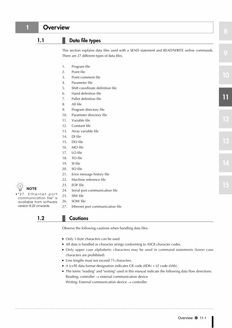
Overview 11-1
8
9
10
11
12
13
14
15
1 Overview
1.1 Data file types
This section explains data files used with a SEND statement and READ/WRITE online commands.
There are 27 different types of data files.
Program file1.
Point file2.
Point comment file3.
Parameter file4.
Shift coordinate definition file5.
Hand definition file6.
Pallet definition file7.
All file8.
Program directory file9.
Parameter directory file10.
Variable file11.
Constant file12.
Array variable file13.
DI file14.
DO file15.
MO file16.
LO file17.
TO file18.
SI file19.
SO file20.
Error message history file21.
Machine reference file22.
EOF file23.
Serial port communication file24.
SIW file25.
SOW file26.
Ethernet port communication file27.
1.2 Cautions
Observe the following cautions when handling data files.
Only 1-byte characters can be used. ■
All data is handled as character strings conforming to ASCII character codes. ■
Only upper case alphabetic characters may be used in command statements (lower case ■
characters are prohibited).
Line lengths must not exceed 75 characters. ■
A [cr/lf] data format designation indicates CR code (0Dh) + LF code (0Ah). ■
The terms "reading" and "writing" used in this manual indicate the following data flow directions: ■
Reading: controller → external communication device
Writing: External communication device → controller
n NOTE
" 2 7 . E t h e r n e t p o r t •communication f i le" is available from software version 8.22 onwards.

11-2 Chapter 11 Data file description
8
9
10
11
12
13
14
15
2 Program file
2.1 All programs
Format
PGM
Meaning • Expressesallprograms.
• Whenusedasareadoutfile,allprogramscurrentlystoredarereadout.
• Writefilesareregisteredat thecontrollerundertheprogramnameindicatedat the
NAME = <program name> line.
DATA FORMAT
NAME = <program name> [cr/lf]aaaaa ...aaaaaaaaaaaaaa[cr/lf] :
aaaaa ...aaaaaaaaaaaaaa[cr/lf] :
NAME = <program name> [cr/lf]aaaaa ...aaaaaaaaaaaaaa[cr/lf] :
aaaaa ...aaaaaaaaaaaaaa[cr/lf][cr/lf]
Values a ............................................Character code
<Program names> are shown with 8 characters or less consisting of alphanumeric characters and ■
underscore ( _ ).
A line containing only [cr/lf] is added at the end of the file, indicating the end of the file. ■
A TAB code (09H) is converted to a space. ■
SAMPLE
SEND PGM TO CMU ・・・・・・・・・・・・・・・・ Outputs all programs from communication port.
SENDCMU TO PGM ・・・・・・・・・・・・・・・・・ Inputs all programs from communication port.
Response:NAME=TEST[cr/lf]A=1[cr/lf]RESET DO2()[cr/lf] :HALT[cr/lf][cr/lf]
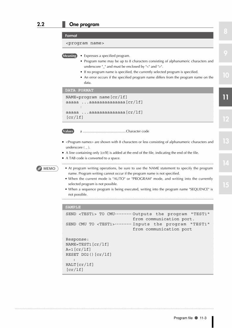
Program file 11-3
8
9
10
11
12
13
14
15
2.2 One program
Format
<program name>
Meaning • Expressesaspecifiedprogram.
• Programnamemaybeupto8charactersconsistingofalphanumericcharactersand
underscore "_" and must be enclosed by "<" and ">".
• Ifnoprogramnameisspecified,thecurrentlyselectedprogramisspecified.
• Anerroroccursifthespecifiedprogramnamediffersfromtheprogramnameonthe
data.
DATA FORMAT
NAME=program name[cr/lf]aaaaa ...aaaaaaaaaaaaaa[cr/lf] :
aaaaa ...aaaaaaaaaaaaaa[cr/lf][cr/lf]
Values a ............................................Character code
<Program names> are shown with 8 characters or less consisting of alphanumeric characters and ■
underscore ( _ ).
A line containing only [cr/lf] is added at the end of the file, indicating the end of the file. ■
A TAB code is converted to a space. ■
•At program writing operations, be sure to use the NAME statement to specify the program
name. Program writing cannot occur if the program name is not specified.
•When thecurrentmode is "AUTO"or "PROGRAM"mode,andwriting into thecurrently
selected program is not possible.
•Whenasequenceprogramisbeingexecuted,writingintotheprogramname"SEQUENCE"is
not possible.
SAMPLE
SEND <TEST1> TO CMU ・・・・・・・・・・ Outputs the program "TEST1" from communication port.
SEND CMU TO <TEST1> ・・・・・・・・・・ Inputs the program "TEST1" from communication port
Response:NAME=TEST1[cr/lf]A=1[cr/lf]RESET DO2()[cr/lf] :HALT[cr/lf][cr/lf]
MEMO

11-4 Chapter 11 Data file description
8
9
10
11
12
13
14
15
3 Point file
3.1 All points
Format
PNT
Meaning • Expressesallpointdata.
• Whenusedasareadoutfile,allpointscurrentlystoredarereadout.
• Whenusedasawritefile,writingisperformedwithapointnumber.
DATA FORMAT (On robots other than YK500TW)
Pmmmm=fxxxxxx fyyyyyy fzzzzzz frrrrrr faaaaaa fbbbbbb t[cr/lf]Pmmmm=fxxxxxx fyyyyyy fzzzzzz frrrrrr faaaaaa fbbbbbb t[cr/lf] :Pmmmm=fxxxxxx fyyyyyy fzzzzzz frrrrrr faaaaaa fbbbbbb t[cr/lf]Pmmmm=fxxxxxx fyyyyyy fzzzzzz frrrrrr faaaaaa fbbbbbb t[cr/lf][cr/lf]
DATA FORMAT(On robot YK500TW, with software Ver.10.66 or later)
Pmmmm= fxxxxxx fyyyyyy fzzzzzz frrrrrr faaaaaa fbbbbbb t xr yr [cr/lf]Pmmmm= fxxxxxx fyyyyyy fzzzzzz frrrrrr faaaaaa fbbbbbb t xr yr [cr/lf] :Pmmmm= fxxxxxx fyyyyyy fzzzzzz frrrrrr faaaaaa fbbbbbb t xr yr [cr/lf]Pmmmm= fxxxxxx fyyyyyy fzzzzzz frrrrrr faaaaaa fbbbbbb t xr yr [cr/lf][cr/lf]
Values mmmm ................... Point No.: 0 to 9999
f .............................. Coordinate sign: + / - / space
xxxxxx/../bbbbbb .... Represent a numeric value of 8 digits or less. When a dot is
included, this is treated as point data in "mm" units. Each piece
of data is separated by one or more spaces.
t .............................. Extended hand system flag setting for SCARA robots. 1: right
hand system; 2: left hand system.
xr ............................ Extended setting's X-arm rotation information.
0 : The "mm → pulse" converted angle data x (*1) range is –180.00° < x < = 180.00°.
1 : The "mm → pulse" converted angle data x (*1) range is 180.00° < x < = 540.00°.
-1 : The "mm → pulse" converted angle data x (*1) range is -540.00° < x < = -180.00°.
yr ............................ Extended setting's Y-arm rotation information.
0 : The "mm → pulse" converted angle data x (*1) range is –180.00° < y < = 180.00°.
1 : The "mm → pulse" converted angle data x (*1) range is 180.00° < y < = 540.00°.
-1 : The "mm → pulse" converted angle data x (*1) range is -540.00° < y < = -180.00°.
*1: The joint-coordinates-converted pulse data represents each arm's distance (converted to
angular data) from its mechanical origin point.
■ Hand system flags are valid only for SCARA robots, with the coordinate data specified in "mm"
units.
If a number other than "1" or "2" is specified for a hand system flag, or if no number is specified, ■
this is interpreted as "0" setting (no hand system flag).
n NOTE
I n c o n t r o l l e r s w h o s e •software version is earlier t h a n 8 . 2 8 , " m m m m " represents a number from 0 to 4000.
Hand system flags are •available from software version 8.08 onwards.
In teger po in t data i s •recognized in pulse units, and real number point data i s recognized in "mm" units.
The X-ar m and Y-ar m •rotation information is only available in software version 10.66 onwards.

Point file 11-5
8
9
10
11
12
13
14
15
X-arm and Y-arm rotation information settings are available only on the YK500TW robot model ■
where a "mm" units coordinate system has been set.
X-arm and Y-arm rotation information is processed as "0" if a numeral other than 0, 1, -1 has been ■
specified, or if no numeral has been specified.
A line containing only [cr/lf] is added at the end of the file to indicate the end of the file. ■
SAMPLE (On robots other than YK500TW)
SEND PNT TO CMU ・・・・・・・・・・・・・・・・ Outputs all points from communication port.
SEND CMU TO PNT ・・・・・・・・・・・・・・・・ I n p u t s a l l p o i n t s f r o m communication port.
Response:P0 = 1 2 3 4 5 6 [cr/lf]P1 = 1.00 2.00 3.00 4.00 5.00 6.00 [cr/lf]P2 = 1.00 0.00 0.00 0.00 0.00 0.00 [cr/lf] :P9999= -1.00 0.00 0.00 0.00 0.00 0.00 [cr/lf][cr/lf]
SAMPLE (On robot YK500TW, with software Ver.10.66 or later)
SEND PNT TO CMU ・・・・・・・・・・・・・・・・ Outputs all points from communication port.
SEND CMU TO PNT ・・・・・・・・・・・・・・・・ I n p u t s a l l p o i n t s f r o m communication port.
Response:P0 = 1 2 3 4 5 6 [cr/lf]P1 = 426.20 -160.77 0.01 337.21 0.00 0.00 0 1 0 [cr/lf]P2 = -27.57 -377.84 0.36 193.22 0.00 0.00 0 -1 0 [cr/lf] :P9999= -251.66 -419.51 0.00 -127.79 0.00 0.00 2 -1 -1 [cr/lf][cr/lf]

11-6 Chapter 11 Data file description
8
9
10
11
12
13
14
15
3.2 One point
Format
Pmmmm
Meaning • Expressesaspecifiedpoint.
• "mmmm"mustbefrom0to9999
DATA FORMAT (On robots other than YK500TW)
Pmmmm=fxxxxxx fyyyyyy fzzzzzz frrrrrr faaaaaa fbbbbbb t[cr/lf]
DATA FORMAT (On robot YK500TW, with software Ver.10.66 or later)
Pmmmm= fxxxxxx fyyyyyy fzzzzzz frrrrrr faaaaaa fbbbbbb t xr yr [cr/lf]
Values mmmm ................... Point No.: 0 to 9999
f .............................. Coordinate sign: + / - / space
xxxxxx/../bbbbbb .... Represent a numeric value of 8 digits or less. When a dot is
included, this is treated as point data in "mm" units. Each piece
of data is separated by one or more spaces.
t .............................. Extended hand system flag setting for SCARA robots. 1: right
hand system; 2: left hand system.
xr ............................ X-arm rotation information for the YK500TW robot.
0 : The "mm → pulse" converted pulse data x (*1) range is –180.00° < x < = 180.00°.
1 : The "mm → pulse" converted pulse data x (*1) range is 180.00° < x < = 540.00°.
-1 : The "mm → pulse" converted pulse data x (*1) range is –540.00° < x < = -180.00°.
yr ............................ Y-arm rotation information for the YK500TW robot.
0 : The "mm → pulse" converted pulse data x (*1) range is –180.00° < y < = 180.00°.
1 : The "mm → pulse" converted pulse data x (*1) range is 180.00° < y < = 540.00°.
-1 : The "mm → pulse" converted pulse data x (*1) range is –540.00° < y < = -180.00°.
*1: The joint-coordinates-converted pulse data represents each arm's distance (converted to
angular data) from its mechanical origin point.
■ Hand system flags are valid only for SCARA robots, with the coordinate data specified in "mm"
units.
If a number other than "1" or "2" is specified for a hand system flag, or if no number is specified, ■
this is interpreted as "0" setting (no hand system flag).
X-arm and Y-arm rotation information settings are available only on the YK500TW robot model ■
where a "mm" units coordinate system has been set.
X-arm and Y-arm rotation information is processed as "0" if a numeral other than 0, 1, -1 has been ■
specified, or if no numeral has been specified.
n NOTE
I n c o n t r o l l e r s w h o s e •software version is earlier t h a n 8 . 2 8 , " m m m m " represents a number from 0 to 4000.
n NOTE
Hand system flags are •available from software version 8.08 onwards.
Integers indicate point •data in "pulse" units, and real numbers in "mm" units.
The X-ar m and Y-ar m •rotation information is only available in software version 10.66 onwards.

Point file 11-7
8
9
10
11
12
13
14
15
SAMPLE (On robots other than YK500TW)
SEND P100 TO CMU ・・・・・・・・・・・・・・・ Outputs the specified point from communication port.
SEND CMU TO P100 ・・・・・・・・・・・・・・・ Inputs the specified point from communication port.
Response:P100= 1 2 3 4 5 6[cr/lf]
SAMPLE (On robot YK500TW, with software Ver.10.66 or later)
SEND P100 TO CMU ・・・・・・・・・・・・・・・ Outputs the specified point from communication port.
SEND CMU TO P100 ・・・・・・・・・・・・・・・ Inputs the specified point from communication port.
Response:P100= 1 2 3 4 5 6 0 1 0 [cr/lf]
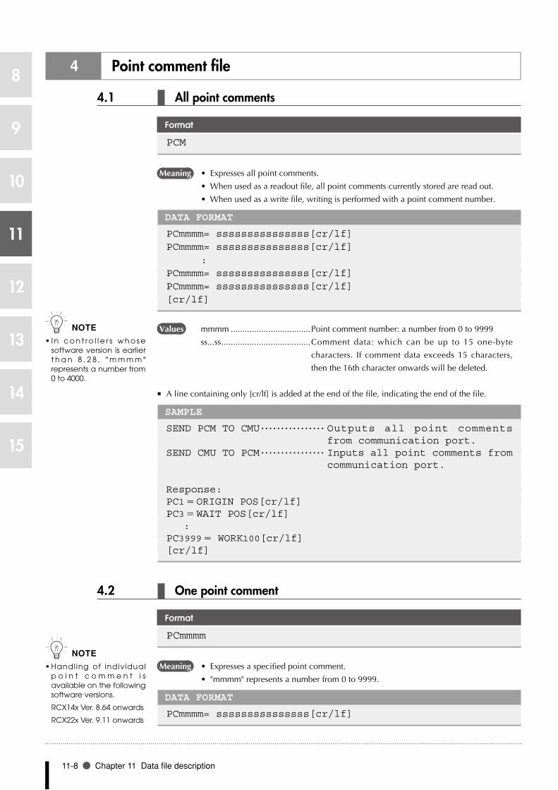
11-8 Chapter 11 Data file description
8
9
10
11
12
13
14
15
4 Point comment file
4.1 All point comments
Format
PCM
Meaning • Expressesallpointcomments.
• Whenusedasareadoutfile,allpointcommentscurrentlystoredarereadout.
• Whenusedasawritefile,writingisperformedwithapointcommentnumber.
DATA FORMAT
PCmmmm= sssssssssssssss[cr/lf]PCmmmm= sssssssssssssss[cr/lf] :PCmmmm= sssssssssssssss[cr/lf]PCmmmm= sssssssssssssss[cr/lf][cr/lf]
Values mmmm ..................................Point comment number: a number from 0 to 9999
ss...ss ...................................... Comment data: which can be up to 15 one-byte
characters. If comment data exceeds 15 characters,
then the 16th character onwards will be deleted.
A line containing only [cr/lf] is added at the end of the file, indicating the end of the file. ■
SAMPLE
SEND PCM TO CMU ・・・・・・・・・・・・・・・・ Outputs all point comments from communication port.
SEND CMU TO PCM ・・・・・・・・・・・・・・・・ Inputs all point comments from communication port.
Response:PC1= ORIGIN POS[cr/lf]PC3= WAIT POS[cr/lf] :PC3999= WORK100[cr/lf][cr/lf]
4.2 One point comment
Format
PCmmmm
Meaning • Expressesaspecifiedpointcomment.
• "mmmm"representsanumberfrom0to9999.
DATA FORMAT
PCmmmm= sssssssssssssss[cr/lf]
n NOTE
I n c o n t r o l l e r s w h o s e •software version is earlier t h a n 8 . 2 8 , " m m m m " represents a number from 0 to 4000.
n NOTE
Handling of individual •p o i n t c o m m e n t i s available on the following software versions.
RCX14x Ver. 8.64 onwards
RCX22x Ver. 9.11 onwards

Point comment file 11-9
8
9
10
11
12
13
14
15
Values mmmm ..................................Point comment number: a number from 0 to 9999
ss...ss ...................................... Comment data: which can be up to 15 one-byte
characters. If comment data exceeds 15 characters,
then the 16th character onwards will be deleted.
SAMPLE
SEND PC1 TO CMU ・・・・・・・・・・・・・・・・ Outputs the specified point comment from communication port.
SEND CMU TO PC1 ・・・・・・・・・・・・・・・・ Inputs the specified point comment from communication port.
Response:PC1= ORIGIN POS[cr/lf]

11-10 Chapter 11 Data file description
8
9
10
11
12
13
14
15
5 Parameter file
5.1 All parameters
Format
PRM
Meaning • Expressesallparameters(includingsettingsin"UTILITY"mode).
• Whenusedasareadoutfile,allparameterscurrentlystoredarereadout.
• Whenusedasawrite file,only theparametersspecifiedbyparameter labelsare
written.
DATA FORMAT
/parameter label/ ’ <comment> [cr/lf]RC= xxxxxx [cr/lf]/parameter label/ ’<comment> [cr/lf]R1= xxxxxx R2= yyyyyy [cr/lf]/parameter label/ ’<comment> [cr/lf]A1= xxxxxx A2= yyyyyy A3= zzzzzz A4= rrrrrr[cr/lf]/parameter label/ ’<comment> [cr/lf] :[cr/lf]
Values RC ..........................................Indicates the entire controller.
R? ...........................................Robot setting: ? / 1: main robot, 2: sub robot
A? ..........................................Axis setting: ?: axis No.
<Comment> ..........................Parameter name
Parameter labels are shown with 6 alphabetic characters. ■
A line containing only [cr/lf] is added at the end of the file, indicating the end of the file. ■
•When writing parameter data, be sure that the servo is off.
•Parametersarealreadycompatiblewithupperversions.However,parametersmightnotalways
be compatible with lower versions (upward compatibility).
•Whenyouattempttoloadaparameterfileofnewversionintoacontrollerofanearlierversion,
an error "10.14 : Undefined parameter found" may appear. If this happens, you may load the
parameter by setting the "Skip undefined parameters" parameter to "VALID". For more details,
refer to the "SYSTEM mode" – "Other parameters" section in the robot controller user's manual.
MEMO

Parameter file 11-11
8
9
10
11
12
13
14
15
5 Parameter file
SAMPLE
SEND PRM TO CMU ・・・・・・・・・・・・・・・・ Outputs all parameters from communication port.
SEND CMU TO PRM ・・・・・・・・・・・・・・ Inputs all parameters from communication port.
Response:/RBTNUM/ ’Robot number (V8.01/R1001)[cr/lf] R1= 3000 R2= 3010 [cr/lf]/AXES / ’Number of axes[cr/lf] R1= 2 R2= 2 [cr/lf]/AXSNUM/ ’Axis number (V1.01/V1.01/V1.01/V1.01/-----/-----/-----/-----/)[cr/lf] A1= 5000 A2= 5001 A3= 5010 A4= 5011 [cr/lf] A5= 0 A6= 0 A7= 0 A8= 0 [cr/lf]/ATTRIB/ ’Axis attribute[cr/lf] A1= 33792 A2= 33792 A3= 33792 A4= 33792 [cr/lf] A5= 256 A6= 256 A7= 256 A8= 256 [cr/lf]/WEIGHT/ ’Tip weight[kg][cr/lf] R1= 2 R2= 12 [cr/lf] :/CURPNO/ ’Port number of output[cr/lf] RC= 20 [cr/lf]/CURPT1/ ’Compare point number1[cr/lf] RC= 0 [cr/lf]/CURPT2/ ’Compare point number2[cr/lf] RC= 0 [cr/lf][cr/lf]

11-12 Chapter 11 Data file description
8
9
10
11
12
13
14
15
5.2 One parameter
Format
/parameter label/
Meaning • Parameterlabelsareshownwith6alphabeticcharacters.
• Whenusedasareadout file,only theparameterspecifiedbyaparameter label is
read out.
• When used as a write file, only the parameter specified by a parameter label is written.
DATA FORMAT 1
/parameter label/ ’<comment>[cr/lf]RC= xxxxxx [cr/lf][cr/lf]
DATA FORMAT 2
/parameter label/ ’<comment>[cr/lf]R?= xxxxxx [cr/lf][cr/lf]
DATA FORMAT 3
/parameter label/ ’<comment>[cr/lf]A?= xxxxxx[cr/lf][cr/lf]
Values RC ..........................................Indicates the entire controller.
R? ...........................................Robot setting: ? / 1: main robot, 2: sub robot
A? ..........................................Axis setting: ?: axis No.
<Comment> ..........................Parameter name
Parameter labels are shown with 6 alphabetic characters. ■
A line containing only [cr/lf] is added at the end of the file, indicating the end of the file. ■
•When writing parameter data, be sure that the servo is off.
•Parametersarealreadycompatiblewithupperversions.However,parametersmightnotalways
be compatible with lower versions (upward compatibility).
•Whenyouattempttoloadaparameterfileofnewversionintoacontrollerofanearlierversion,
an error "10.14 : Undefined parameter found" may appear.
SAMPLE
SEND /ACCEL / TO CMU ・・・・・・ Outputs the acceleration parameter from communication port.
SEND CMU TO /ACCEL / ・・・・・・・・ Inputs the acceleration parameter from communication port.
Response:/ACCEL / ’Accel coefficient[%]A1= 100 A2= 100 A3= 100 A4= 100[cr/lf][cr/lf]
MEMO

Shift coordinate definition file 11-13
8
9
10
11
12
13
14
15
6 Shift coordinate definition file
6.1 All shift data
Format
SFT
Meaning • Expressesallshiftdata.
• Whenusedasareadoutfile,allshiftdatacurrentlystoredarereadout.
• Whenusedasawritefile,writingisperformedwithashiftnumber.
DATA FORMAT
Sm = fxxxxxx fyyyyyy fzzzzzz frrrrrr [cr/lf]SPm = fxxxxxx fyyyyyy fzzzzzz frrrrrr [cr/lf]SMm = fxxxxxx fyyyyyy fzzzzzz frrrrrr [cr/lf] :Sm = fxxxxxx fyyyyyy fzzzzzz frrrrrr [cr/lf]SPm = fxxxxxx fyyyyyy fzzzzzz frrrrrr [cr/lf]SMm = fxxxxxx fyyyyyy fzzzzzz frrrrrr [cr/lf][cr/lf]
Values m ...........................................Shift No.: 0 to 9
f .............................................Coordinate sign: + / - / space
xxxxxx/yyyyyy/../rrrrrr ............ Represent a numeric value of 8 digits or less, having 2
or less places below the decimal point.
The SPm and SMm inputs are optional in writing files. ■
SPm: shift coordinate range plus-side; SMm: shift coordinate range minus-side
A line containing only [cr/lf] is added at the end of the file, indicating the end of the file. ■
SAMPLE
SEND SFT TO CMU ・・・・・・・・・・・・・・・・ Outputs all shift data from communication port.
SEND CMU TO SFT ・・・・・・・・・・・・・・・・ Inputs all shift data from communication port.
Response:S0 = 0.00 0.00 0.00 0.00 [cr/lf]SP0= 0.00 0.00 0.00 0.00 [cr/lf]SM0= 0.00 0.00 0.00 0.00 [cr/lf]S1 = 1.00 1.00 1.00 1.00 [cr/lf] :SM9= 9.00 9.00 9.00 9.00 [cr/lf][cr/lf]
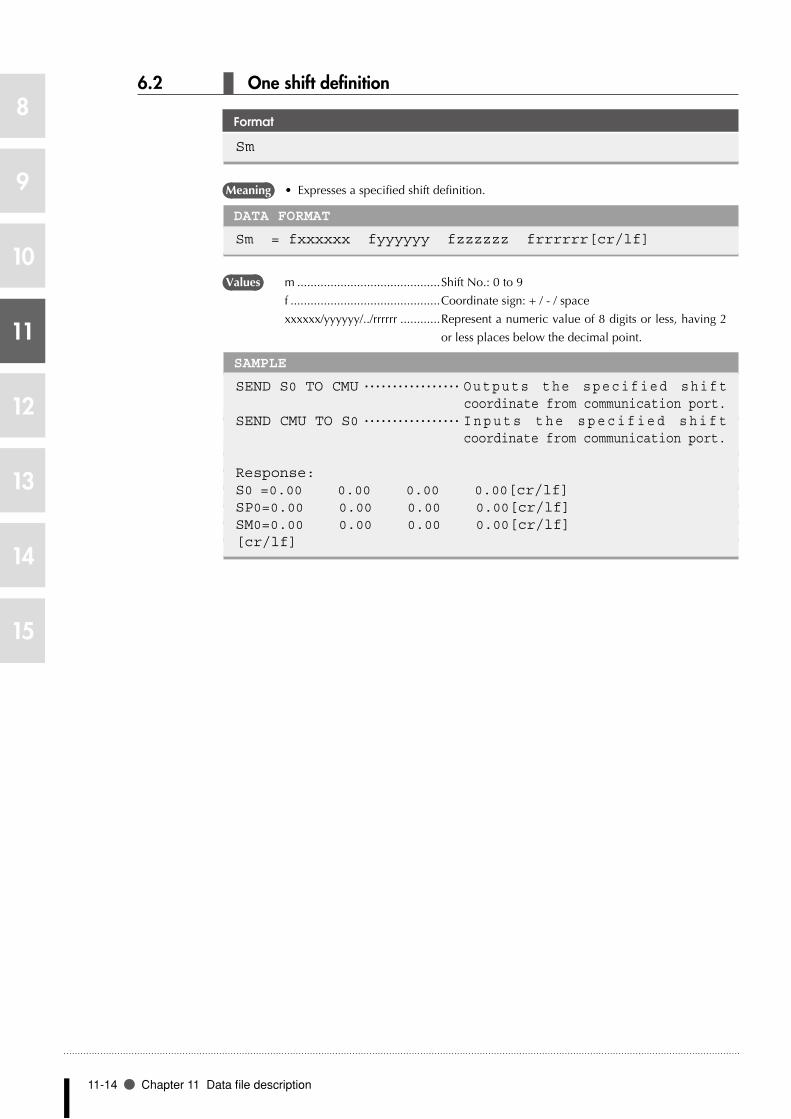
11-14 Chapter 11 Data file description
8
9
10
11
12
13
14
15
6.2 One shift definition
Format
Sm
Meaning • Expressesaspecifiedshiftdefinition.
DATA FORMAT
Sm = fxxxxxx fyyyyyy fzzzzzz frrrrrr[cr/lf]
Values m ...........................................Shift No.: 0 to 9
f .............................................Coordinate sign: + / - / space
xxxxxx/yyyyyy/../rrrrrr ............ Represent a numeric value of 8 digits or less, having 2
or less places below the decimal point.
SAMPLE
SEND S0 TO CMU ・・・・・・・・・・・・・・・・・ Outputs the specified shift coordinate from communication port.
SEND CMU TO S0 ・・・・・・・・・・・・・・・・・ I n p u t s t h e s p e c i f i e d s h i f t coordinate from communication port.
Response:S0 = 0.00 0.00 0.00 0.00[cr/lf]SP0= 0.00 0.00 0.00 0.00[cr/lf]SM0= 0.00 0.00 0.00 0.00[cr/lf][cr/lf]

Hand definition file 11-15
8
9
10
11
12
13
14
15
7 Hand definition file
7.1 All hand data
Format
HND
Meaning • Expressesallhanddata.
• Whenusedasareadoutfile,allhanddatacurrentlystoredarereadout.
• Whenusedasawritefile,writingisperformedwithahandnumber.
DATA FORMAT
Hm = fxxxxxx fyyyyyy fzzzzzz {R}[cr/lf] :Hm = fxxxxxx fyyyyyy fzzzzzz {R}[cr/lf][cr/lf]
Values m ........................................... Hand number / 0 to 3: used for main robot, 4 to 7: used
for sub robot
f .............................................Coordinate sign: + / - / space
xxxxxx/yyyyyy/zzzzzz ............ Represent a numeric value of 8 digits or less, having 2
or less places below the decimal point, or an integer of
7 digits or less. (This numeric format depends on the
robot type setting and hand definition type.)
{R} ..........................................Indicates whether a hand is attached to the R-axis.
A line containing only [cr/lf] is added at the end of the file, indicating the end of the file. ■
SAMPLE
SEND HND TO CMU ・・・・・・・・・・・・・・・・ Outputs all hand data from communication port.
SEND CMU TO HND ・・・・・・・・・・・・・・・・ Inputs all hand data from communication port.
Response:H0 = 0.00 0.00 0.00 [cr/lf]H1 = 1.00 1.00 1.00 [cr/lf]H2 = 2.00 2.00 2.00 [cr/lf]H3 = 3.00 3.00 3.00 [cr/lf]H4 = 4.00 4.00 4.00 [cr/lf]H5 = 5.00 5.00 5.00 [cr/lf]H6 = 6.00 6.00 6.00 [cr/lf]H7 = 7.00 7.00 7.00 [cr/lf][cr/lf]

11-16 Chapter 11 Data file description
8
9
10
11
12
13
14
15
7.2 One hand definition
Format
Hm
Meaning • Expressesaspecifiedhanddefinition.
DATA FORMAT
Hm = fxxxxxx fyyyyyy fzzzzzz {R}[cr/lf]
Values m ........................................... Hand number / 0 to 3: used for main robot, 4 to 7: used
for sub robot
f .............................................Coordinate sign: + / - / space
xxxxxx/yyyyyy/zzzzzz ............ Represent a numeric value of 8 digits or less, having 2
or less places below the decimal point, or an integer of
7 digits or less. (This numeric format depends on the
robot type setting and hand definition type.)
{R} ..........................................Indicates whether a hand is attached to the R-axis.
SAMPLE
SEND H3 TO CMU ・・・・・・・・・・・・・・・・・ Outputs the specified hand definition data from communication port.
SEND CMU TO H3 ・・・・・・・・・・・・・・・・・ Inputs the specified hand definition data from communication port.
Response:H3 = 3.00 3.00 3.00[cr/lf]

Pallet definition file 11-17
8
9
10
11
12
13
14
15
8 Pallet definition file
8.1 All pallet definitions
Format
PLT
Meaning • Expressesallpalletdefinitions.
• Whenusedasareadoutfile,allpalletdefinitionscurrentlystoredarereadout.
• Whenusedasawritefile,writingisperformedwithapalletnumber.
DATA FORMAT (On robots other than YK500TW)
PLm [cr/lf]PLN = XY [cr/lf]NX = nnn [cr/lf]NY = nnn [cr/lf]NZ = nnn [cr/lf]P[1] = fxxxxxx fyyyyyy fzzzzzz frrrrrr faaaaaa fbbbbbb t[cr/lf] :P[5] = fxxxxxx fyyyyyy fzzzzzz frrrrrr faaaaaa fbbbbbb t[cr/lf]PLm [cr/lf] :[cr/lf]
DATA FORMAT (On robot YK500TW, with software Ver.10.66 or later)
PLm [cr/lf]PLN = XY [cr/lf]NX = nnn [cr/lf]NY = nnn [cr/lf]NZ = nnn [cr/lf]P[1] = fxxxxxx fyyyyyy fzzzzzz frrrrrr faaaaaa fbbbbbb t xr yr[cr/lf] :P[5] = fxxxxxx fyyyyyy fzzzzzz frrrrrr faaaaaa fbbbbbb t xr yr[cr/lf]PLm [cr/lf] :[cr/lf]
Values m ..................... Pallet number: 0 to 19
nnn .................. Number of axis points: positive integer
f ....................... Coordinate sign: + / - / space
xxxxxx/yyyyyy/../bbbbbb .........
Represent a numeric value of 8 digits or less. When a dot is included,
this is treated as coordinate data in "mm" units. Each piece of data is
separated by one or more spaces.
t ....................... An extended hand system flag setting for SCARA robots. 1: Right-
handed system, 2: Left-handed system
xr ..................... Extended setting for X-arm rotation information.
0: "mm" → pulse converted angle data x (*1) range: -180.00°< x <= 180.00°
1: "mm" → pulse converted angle data x (*1) range: 180.00° < x <= 540.00°
-1: "mm" → pulse converted angle data x (*1) range: -540.00° < x <= -180.00°
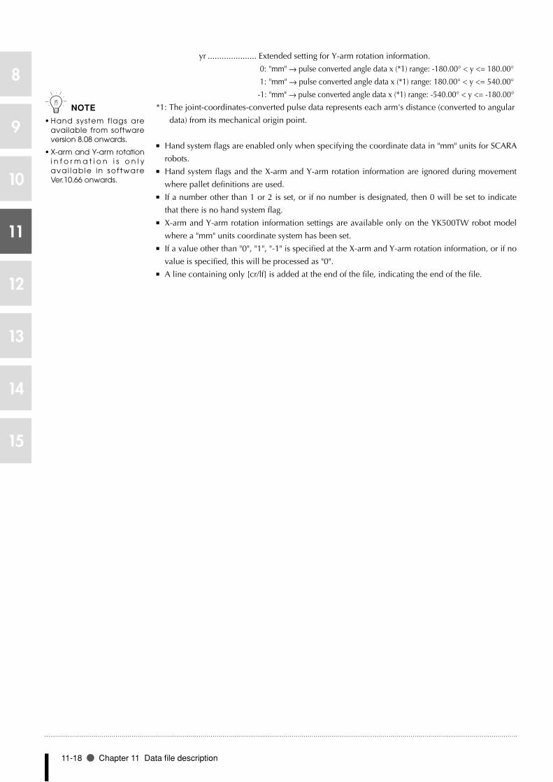
11-18 Chapter 11 Data file description
8
9
10
11
12
13
14
15
yr ..................... Extended setting for Y-arm rotation information.
0: "mm" → pulse converted angle data x (*1) range: -180.00° < y <= 180.00°
1: "mm" → pulse converted angle data x (*1) range: 180.00° < y <= 540.00°
-1: "mm" → pulse converted angle data x (*1) range: -540.00° < y <= -180.00°
*1: The joint-coordinates-converted pulse data represents each arm's distance (converted to angular
data) from its mechanical origin point.
■ Hand system flags are enabled only when specifying the coordinate data in "mm" units for SCARA
robots.
Hand system flags and the X-arm and Y-arm rotation information are ignored during movement ■
where pallet definitions are used.
If a number other than 1 or 2 is set, or if no number is designated, then 0 will be set to indicate ■
that there is no hand system flag.
X-arm and Y-arm rotation information settings are available only on the YK500TW robot model ■
where a "mm" units coordinate system has been set.
If a value other than "0", "1", "-1" is specified at the X-arm and Y-arm rotation information, or if no ■
value is specified, this will be processed as "0".
A line containing only [cr/lf] is added at the end of the file, indicating the end of the file. ■
n NOTE
Hand system flags are •available from software version 8.08 onwards.
X-arm and Y-arm rotation •i n f o r m a t i o n i s o n l y avai lable in sof tware Ver.10.66 onwards.
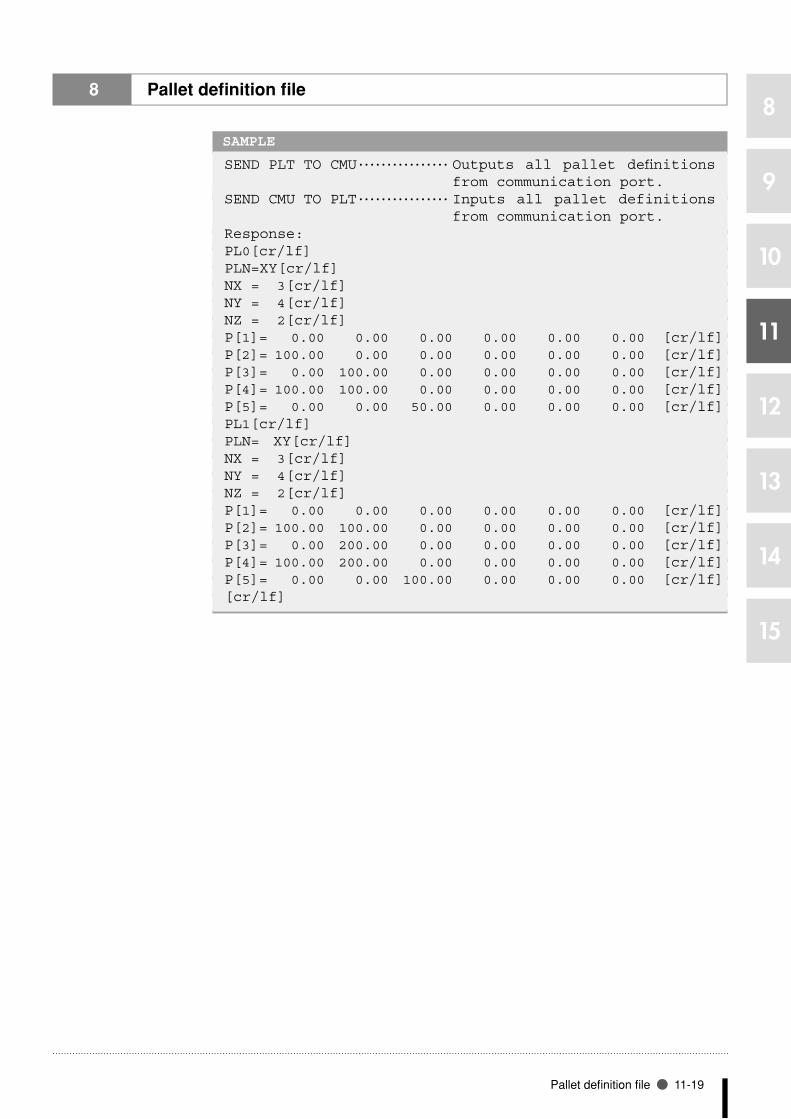
Pallet definition file 11-19
8
9
10
11
12
13
14
15
8 Pallet definition file
SAMPLE
SEND PLT TO CMU ・・・・・・・・・・・・・・・・ Outputs all pallet definitions from communication port.
SEND CMU TO PLT ・・・・・・・・・・・・・・・・ Inputs all pallet definitions from communication port.
Response:PL0[cr/lf]PLN=XY[cr/lf]NX = 3 [cr/lf]NY = 4 [cr/lf]NZ = 2 [cr/lf]P[1]= 0.00 0.00 0.00 0.00 0.00 0.00 [cr/lf]P[2]= 100.00 0.00 0.00 0.00 0.00 0.00 [cr/lf]P[3]= 0.00 100.00 0.00 0.00 0.00 0.00 [cr/lf]P[4]= 100.00 100.00 0.00 0.00 0.00 0.00 [cr/lf]P[5]= 0.00 0.00 50.00 0.00 0.00 0.00 [cr/lf]PL1[cr/lf]PLN= XY[cr/lf]NX = 3[cr/lf]NY = 4[cr/lf]NZ = 2[cr/lf]P[1]= 0.00 0.00 0.00 0.00 0.00 0.00 [cr/lf]P[2]= 100.00 100.00 0.00 0.00 0.00 0.00 [cr/lf]P[3]= 0.00 200.00 0.00 0.00 0.00 0.00 [cr/lf]P[4]= 100.00 200.00 0.00 0.00 0.00 0.00 [cr/lf]P[5]= 0.00 0.00 100.00 0.00 0.00 0.00 [cr/lf][cr/lf]

11-20 Chapter 11 Data file description
8
9
10
11
12
13
14
15
8.2 One pallet definition
Format
PLm
Meaning • Expressesaspecifiedpalletdefinition.
• "m"mustbefrom0to19.
DATA FORMAT (On robots other than YK500TW)
PLm [cr/lf]PLN = XY [cr/lf]NX = nnn [cr/lf]NY = nnn [cr/lf]NZ = nnn [cr/lf]P[1] = fxxxxxx fyyyyyy fzzzzzz frrrrrr faaaaaa fbbbbbb t[cr/lf] :P[5] = fxxxxxx fyyyyyy fzzzzzz frrrrrr faaaaaa fbbbbbb t[cr/lf][cr/lf]
DATA FORMAT (On robot YK500TW, with software Ver.10.66 or later)
PLm [cr/lf]PLN = XY [cr/lf]NX = nnn [cr/lf]NY = nnn [cr/lf]NZ = nnn [cr/lf]P[1] = fxxxxxx fyyyyyy fzzzzzz frrrrrr faaaaaa fbbbbbb t xr yr[cr/lf] :P[5] = fxxxxxx fyyyyyy fzzzzzz frrrrrr faaaaaa fbbbbbb t xr yr[cr/lf][cr/lf]
Values m ..................... Pallet number: 0 to 19
nnn .................. Number of points for each axis: positive integer
f ....................... Coordinate sign: + / - / space
xxxxxx/yyyyyy/../bbbbbb .........
Represent a numeric value of 8 digits or less. When a dot is
included, this is treated as point data in "mm" units. Each piece of
data is separated by one or more spaces.
t ....................... An extended hand system flag setting for SCARA robots. 1: Right-
handed system, 2: Left-handed system
xr ..................... Extended setting for X-arm rotation information.
0: "mm" → pulse converted angle data x (*1) range: -180.00° < x <= 180.00°
1: "mm" → pulse converted angle data x (*1) range: 180.00° < x <= 540.00°
-1: "mm" → pulse converted angle data x (*1) range: -540.00° < x <= -180.00°
yr ..................... Extended setting for Y-arm rotation information.
0: "mm" → pulse converted angle data x (*1) range: -180.00° < y <= 180.00°
1: "mm" → pulse converted angle data x (*1) range: 180.00° < y <= 540.00°
-1: "mm" → pulse converted angle data x (*1) range: -540.00° < y <= -180.00°
*1: The joint-coordinates-converted pulse data represents each arm's distance (converted to angular
data) from its mechanical origin point.
n NOTE
Integers indicate point •data in "pulse" units, and real numbers in "mm" units.

Pallet definition file 11-21
8
9
10
11
12
13
14
15
■ Hand system flags are enabled only when specifying the coordinate data in "mm" units for SCARA
robots.
Hand system flags and the X-arm and Y-arm rotation information are ignored during movement ■
where pallet definitions are used.
If a number other than 1 or 2 is set, or if no number is designated, then 0 will be set to indicate ■
that there is no hand system flag.
X-arm and Y-arm rotation information settings are available only on the YK500TW robot model ■
where a "mm" units coordinate system has been set.
If a value other than "0", "1", "-1" is specified at the X-arm and Y-arm rotation information, or if no ■
value is specified, this will be processed as "0".
A line containing only [cr/lf] is added at the end of the file, indicating the end of the file. ■
n NOTE
Hand system flags are •available from software version 8.08 onwards.
X-arm and Y-arm rotation •i n f o r m a t i o n i s o n l y avai lable in sof tware Ver.10.66 onwards.

11-22 Chapter 11 Data file description
8
9
10
11
12
13
14
15
8 Pallet definition file
SAMPLE
SEND PL2 TO CMU ・・・・・・・・・・・・・・・・ Outputs the specified pallet definition from communication port as shown below.
SEND CMU TO PL2 ・・・・・・・・・・・・・・・・ Inputs the specified pallet definition from communication port as shown below.
Response:PL2[cr/lf]PLN=XY[cr/lf]NX= 3[cr/lf]NY= 3[cr/lf]NZ= 2[cr/lf]P[1]= 100.00 100.00 50.00 90.00 0.00 0.00 [cr/lf]P[2]= 200.00 100.00 50.00 90.00 0.00 0.00 [cr/lf]P[3]= 100.00 200.00 50.00 90.00 0.00 0.00 [cr/lf]P[4]= 200.00 200.00 50.00 90.00 0.00 0.00 [cr/lf]P[5]= 100.00 10.00 100.00 90.00 0.00 0.00 [cr/lf][cr/lf]

All file 11-23
8
9
10
11
12
13
14
15
9 All file
9.1 All files
Format
ALL
Meaning Expresses the minimum number of data files required to operate the robot system.
DATA FORMAT
[PGM] All program formatNAME=< program name >aaaaa ・・・aaaaaaaaaaaaaa[cr/lf]:
aaaaa ・・・aaaaaaaaaaaaaa[cr/lf][cr/lf][PNT] All point formatPmmmm=fxxxxxx fyyyyyy fzzzzzz frrrrrr faaaaaa fbbbbbb t[cr/lf]:
Pmmmm=fxxxxxx fyyyyyy fzzzzzz frrrrrr faaaaaa fbbbbbb t[cr/lf][cr/lf][PCM] All point comment formatPCmmmm= sssssssssssssss[cr/lf]:PCmmmm= sssssssssssssss[cr/lf][cr/lf][PRM] All parameter format/parameter label/'<comment> [cr/lf]RC= xxxxxx [cr/lf]/parameter label/'<comment> [cr/lf]R1= xxxxxx R2= yyyyyy [cr/lf]:[cr/lf][END] ALL files end
• In writing files, [xxx] determines the data file's format, and this format is saved at the controller.
Example: [HND]…All text data up the next [xxx] is saved at the controller as "all hand" format
data.
SAMPLE
SEND ALL TO CMU ・・・・・・・・・・・・・・・・ Outputs all files of the entire system from communication port.
SEND CMU TO ALL ・・・・・・・・・・・・・・・・ Inputs all files of the entire system from communication port.
n NOTE
F o r d e t a i l s o f e a c h •f i le, refer to that f i le's explanation.
MEMO

11-24 Chapter 11 Data file description
8
9
10
11
12
13
14
15
10 Program directory file
10.1 Entire program directory
Format
DIR
Meaning • Expressesentireprogramdirectory.
• Whenusedasareadoutfile,informationonentireprogramdirectoryisreadout.
• Cannotbeusedasawritefile.
DATA FORMAT
No. Name Line Byte RW/RO Date Time[cr/lf]nnnfgssssssss llll bbbbbb xx yy/mm/dd hh:mm[cr/lf] :nnnfgssssssss llll bbbbbb xx yy/mm/dd hh:mm[cr/lf]END[cr/lf]
Values nnn ........................................Program directory number: 3 digits
f ............................................. "o" at program compiling when a program object is
created. "s" at sequence program compiling when a
sequence object is created.
g ............................................Shows an asterisk "*" for the currently selected program.
ssssssss ...................................Program name: 8 digits
llll ..........................................Number of program lines: 4 digits
bbbbbb ..................................Byte size of program: 6 digits
xx ...........................................File attribute: 2-digit
RW: Readable/writable
RO: Not writable (read only)
yy/mm/dd .............................. Date when the program was updated: 8 digits (including
the "/" marks)
hh:mm ..................................Time when the program was updated: 5 digits
SAMPLE
SEND DIR TO CMU ・・・・・・・・・・・・・・・・ Outputs information on all program directory from communication port.
Response:No. Name Line Byte RW/RO Date Time[cr/lf]1o* 12345678 5 21 RW 01/06/20 10:35[cr/lf]2 PGM1 5 66 RW 01/06/20 10:35[cr/lf]3 PGM2 5 66 RW 01/06/20 10:35[cr/lf]4 PGM3 5 66 RW 01/06/20 10:35[cr/lf]5 PGM4 5 66 RW 01/06/20 10:35[cr/lf]6 PGM5 5 66 RW 01/06/20 10:35[cr/lf]7 PGM6 5 66 RW 01/06/20 10:35[cr/lf]8s SEQUENCE 1 15 RW 01/06/20 10:35[cr/lf]END[cr/lf]

Program directory file 11-25
8
9
10
11
12
13
14
15
10.2 One program
Format
“<<”<program name>”>>”
Meaning • Expressesinformationononeprogram.
• Theprogramnameisenclosedin<<>>doublebrackets.
DATA FORMAT
No. Name Line Byte RW/RO Date Time[cr/lf]nnnfgssssssss llll bbbbbb xx yy/mm/dd hh:mm[cr/lf]
Values nnn ........................................Program directory number: 3 digits
f ............................................. "o" at program compiling when a program object is
created. "s" at sequence program compiling when a
sequence object is created.
g ............................................Shows an asterisk "*" for the currently selected program.
ssssssss ...................................Program name: 8 digits
llll ..........................................Number of program lines: 4 digits
bbbbbb ..................................Byte size of program: 6 digits
xx ...........................................File attribute: 2-digit
RW: Readable/writable
RO: Not writable (read only)
yy/mm/dd .............................. Date when the program was updated: 8 digits (including
the "/" marks)
hh:mm ..................................Time when the program was updated: 5 digits
•Indicates the compiled execution program (program objects compiled for a robot program, or
sequence objects compiled for a sequence program).
SAMPLE
SEND <<TEST>> TO CMU ・・・・・・・・ Outputs information on the specified program from communication port.
Response:No. Name Line Byte RW/RO Date Time[cr/lf]3o* PGM2 5 66 RW 01/06/20 10:35[cr/lf]
MEMO

11-26 Chapter 11 Data file description
8
9
10
11
12
13
14
15
11 Parameter directory file
11.1 Entire parameter directory
Format
DPM
Meaning • Expressesentireparameterdirectory.
• Whenusedasareadoutfile,informationonentireparameterdirectoryisreadout.
• Cannotbeusedasawritefile.
DATA FORMAT
/parameter label/ ’<comment>[cr/lf]/parameter label/ ’<comment>[cr/lf] :/parameter label/ ’<comment>[cr/lf] [cr/lf]
Values <comment> .......................... Parameter name
Parameter labels are shown with 6 alphabetic characters. ■
A line containing only [cr/lf] is added at the end of the file, indicating the end of the file. ■
SAMPLE
SEND DPM TO CMU ・・・・・・・・・・・・・・・・ Outputs information on all parameter directory from communication port.
Response:/RBTNUM/ ’Robot number (V8.01/R1001)[cr/lf]/AXES / ’Number of axes[cr/lf]/AXSNUM/ ’Axis number(V1.01/V1.01/V1.01/V1.01/-----/-----/-----/-----/)[cr/lf]/ATTRIB/ ’Axis attribute[cr/lf]/WEIGHT/ ’Tip weight[kg][cr/lf]/ORIGIN/ ’Origin sequence[cr/lf]/RORIEN/ ’R axis orientation[cr/lf] :/CURPNO/ ’Output port number[cr/lf]/CURPT1/ ’Number of compare point 1[cr/lf]/CURPT2/ ’Number of compare point 2[cr/lf][cr/lf]

Variable file 11-27
8
9
10
11
12
13
14
15
12 Variable file
12.1 All variables
Format
VAR
Meaning • Expressesallglobal variables.
• Whenusedasareadoutfile,allglobalvariablescurrentlystoredarereadout.
• Whenusedasawritefile,aspecifiedglobalvariableiswritten.
DATA FORMAT
<variable name>t = xxxxxx [cr/lf]<variable name>t = xxxxxx [cr/lf] :<variable name>t = xxxxxx [cr/lf] [cr/lf]
Values <Variable name> .................. Global variable defined in the program. Variable
name is shown with 16 characters or less consisting of
alphanumeric characters and underscore ("_").
t ............................................. Type of variable / !: real type, %: integer type, $:
character string type
xxxxxx ...................................Differs depending on the type of variable:
Integer type: integer of 8 digits or less
Real type: real number of 7 digits or less including
decimal fractions
Character type: character string of 70 characters or less
A line containing only [cr/lf] is added at the end of the file, indicating the end of the file. ■

11-28 Chapter 11 Data file description
8
9
10
11
12
13
14
15
12 Variable file
SAMPLE 1
SEND VAR TO CMU ・・・・・・・・・・・・・・・・ Outputs all global variables from communication port.
Response:SGI0=0[cr/lf]SGI1=1111[cr/lf]SGI2=2222[cr/lf]SGI3=3333[cr/lf]SGI4=4444[cr/lf]SGI5=5555[cr/lf]SGI6=6666[cr/lf]SGI7=7777[cr/lf]SGR0=0[cr/lf]SGR1=1.1111E3[cr/lf]SGR2=2.2222E3[cr/lf]SGR3=3.3333E3[cr/lf]SGR4=4.4444E3[cr/lf]SGR5=5.5555E3[cr/lf]SGR6=6.6666E3[cr/lf]SGR7=7.7777E3[cr/lf]B1%=111[cr/lf]B2%=222[cr/lf]C1$="CNS_1"[cr/lf]C2$="CNS_2"[cr/lf][cr/lf]
SAMPLE 2
SEND CMU TO VAR ・・・・・・・・・・・・・・・・ Inputs all global variables from communication port.

Variable file 11-29
8
9
10
11
12
13
14
15
12.2 One variable
Format
<variable name>t
Meaning • Expressedonevariable.
DATA FORMAT
xxxxxx [cr/lf]
Values <Variable name> .................. Global variable defined in the program. Variable
name is shown with 16 characters or less consisting of
alphanumeric characters and underscore ("_").
t ............................................. Type of variable / !: real type, %: integer type, $:
character string type
xxxxxx ...................................Differs depending on the type of variable:
Integer type: integer of 8 digits or less
Real type: real number of 7 digits or less including
decimal fractions
Character type: character string of 70 characters or less
•Dynamic global variables are registered during compiling. Variables cannot be referred to
unless they are registered.
SAMPLE 1
SEND SGI6 TO CMU[cr/lf] ・・・ Outputs the specified variable SGI6 from communication port.
Response:6666[cr/lf]
SAMPLE 2
SEND CMU TO SGI6[cr/lf] ・・ Inputs the specified variable SGI6 from communication port.
Response:6666 [cr/lf] ・・・・・・・ Data input to the controller.OK [cr/lf] ・・・・・・・・・・ Result output from the controller.
n NOTE
SGIx indicates an integer •type static variable.
SGRx indicates a real type •static variable.
MEMO
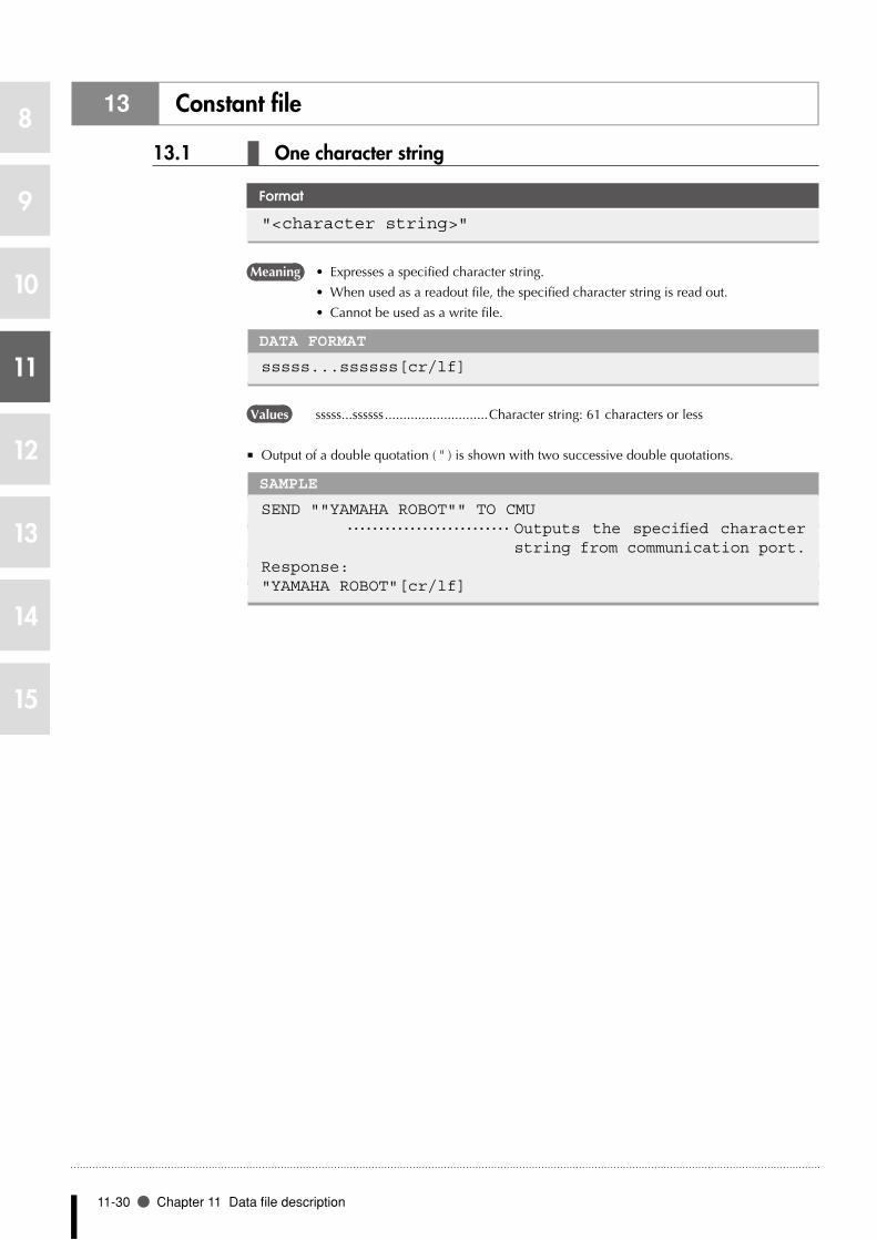
11-30 Chapter 11 Data file description
8
9
10
11
12
13
14
15
13 Constant file
13.1 One character string
Format
"<character string>"
Meaning • Expressesaspecifiedcharacterstring.
• Whenusedasareadoutfile,thespecifiedcharacterstringisreadout.
• Cannotbeusedasawritefile.
DATA FORMAT
sssss...ssssss[cr/lf]
Values sssss...ssssss ............................Character string: 61 characters or less
Output of a double quotation ( " ) is shown with two successive double quotations. ■
SAMPLE
SEND ""YAMAHA ROBOT"" TO CMU ・・・・・・・・・・・・・・・・・・・・・・・・・・ Outputs the specified character
string from communication port.Response:"YAMAHA ROBOT"[cr/lf]

Array variable file 11-31
8
9
10
11
12
13
14
15
14 Array variable file
14.1 All array variables
Format
ARY
Meaning • Expressesallarrayvariables.
• Whenusedasareadoutfile,allarrayvariablesarereadout.
• Whenusedasawritefile,writingisperformedwithaspecifiedarrayvariable.
DATA FORMAT
<variable name>t(l{,m{,n}}) = xxxxxx [cr/lf]<variable name>t(l{,m{,n}}) = xxxxxx [cr/lf] :<variable name>t(l{,m{,n}}) = xxxxxx [cr/lf][cr/lf]
Values <Variable name> .................. Global variable defined in the program. Variable
name is shown with 16 characters or less consisting of
alphanumeric characters and underscore ("_").
t ............................................. Type of variable / !: real type, %: integer type, $: character string type
l, m, n ....................................Indicate array arguments.
xxxxxx ...................................Differs depending on the type of array variable.
Integer type: integer of 8 digits or less
Real type: real number of 7 digits or less including decimal fractions
Character type: character string of 70 characters or less
A line containing only [cr/lf] is added at the end of the file, indicating the end of the file. ■
SAMPLE 1
SEND ARY TO CMU ・・・・・・・・・・・・ Outputs all global array variables from communication port.Response:A!(0)=0[cr/lf]A!(1)=1.E2[cr/lf]A!(2)=2.E2[cr/lf]B%(0,0)=0[cr/lf]B%(0,1)=1111[cr/lf]B%(1,0)=2222[cr/lf]B%(1,1)=3333[cr/lf]C$(0,0,0)="ARY1"[cr/lf]C$(0,0,1)="ARY2"[cr/lf]C$(0,1,0)="ARY3"[cr/lf]C$(0,1,1)="ARY4"[cr/lf]C$(1,0,0)="ARY5"[cr/lf]C$(1,0,1)="ARY6"[cr/lf]C$(1,1,0)="ARY7"[cr/lf]C$(1,1,1)="ARY8"[cr/lf][cr/lf]
SAMPLE 2
SEND CMU TO ARY ・・・・・・・・・・・・ Inputs all global array variables from communication port.

11-32 Chapter 11 Data file description
8
9
10
11
12
13
14
15
14.2 One array variable
Format
<variable name>t(l {,m {,n }})
Meaning • Expressesonearrayvariable.
DATA FORMAT
xxxxxx [cr/lf]
Values <Variable name> .................. Global variable defined in the program. Variable
name is shown with 16 characters or less consisting of
alphanumeric characters and underscore ("_").
t ............................................. Type of variable / !: real type, %: integer type, $:
character string type
l, m, n ....................................Indicate array arguments.
xxxxxx ...................................Differs depending on the type of array variable.
Integer type: integer of 8 digits or less
Real type: real number of 7 digits or less including
decimal fractions
Character type: character string of 70 characters or less
•Array variables defined by the DIM statement are registered during compiling. Array variables
cannot be referred to unless they are registered.
SAMPLE 1
SEND C1$(2) TO CMU[cr/lf] ・・・・ Outputs the specified array variable C1$(2) from communication port.
Response:YAMAHA ROBOT[cr/lf]
SAMPLE 2
SEND CMU TO C1$(2)[cr/lf] ・・・・ Inputs the specified array variable C1$(2) from communication port.
Response:OK[cr/lf]
MEMO

DI file 11-33
8
9
10
11
12
13
14
15
15 DI file
15.1 All DI information
Format
DI()
Meaning • ExpressesallDI(parallelinputvariable)information.
• Whenusedasareadoutfile,allDIinformationisreadout.
• Cannotbeusedasawritefile.
DATA FORMAT
DI0()=&Bnnnnnnnn [cr/lf]DI1()=&Bnnnnnnnn [cr/lf] :DI27()=&Bnnnnnnnn [cr/lf][cr/lf]
Values n ............................................ "0" or "1" (total of 8 digits). Corresponds to m7, m6, …,
m0, reading from the left ("m" is the port No.).
A line containing only [cr/lf] is added at the end of the file, indicating the end of the file. ■
SAMPLE
SEND DI() TO CM ・・・・・・・・・・・・・・・・ Outputs all DI information from communication port.
Response:DI0()=&B10001001[cr/lf]DI1()=&B00000010[cr/lf]DI2()=&B00000000[cr/lf] :DI7()=&B00000000[cr/lf]DI10()=&B00000000[cr/lf]DI11()=&B00000000[cr/lf]DI12()=&B00000000[cr/lf] :DI17()=&B00000000[cr/lf]DI20()=&B00000000[cr/lf] :DI26()=&B00000000[cr/lf]DI27()=&B00000000[cr/lf][cr/lf]

11-34 Chapter 11 Data file description
8
9
10
11
12
13
14
15
15.2 One DI port
Format
DIm()
Meaning • ExpressesthestatusofoneDIport.
• Whenusedasareadoutfile,thespecifiedDIportstatusisreadout.
• Cannotbeusedasawritefile.
DATA FORMAT
DIm()=&Bnnnnnnnn[cr/lf]
Values m ...........................................0 to 7, 10 to 17, 20 to 27
n ............................................ "0" or "1" (total of 8 digits). Corresponds to m7, m6, …,
m0, reading from the left ("m" is the port No.).
SAMPLE
SEND DI5() TO CMU ・・・・・・・・・・・・・ Outputs the DI5 port status from communication port.
Response:DI5()=&B00000000[cr/lf]

DO file 11-35
8
9
10
11
12
13
14
15
16 DO file
16.1 All DO information
Format
DO()
Meaning • ExpressesallDO(paralleloutputvariable)information.
• Whenusedasareadoutfile,allDOinformationisreadout.
• Cannotbeusedasawritefile.
DATA FORMAT
DO0()=&Bnnnnnnnn [cr/lf]DO1()=&Bnnnnnnnn [cr/lf] :DO27()=&Bnnnnnnnn [cr/lf][cr/lf]
Values n ............................................ "0" or "1" (total of 8 digits). Corresponds to m7, m6, …,
m0, reading from the left ("m" is the port No.).
A line containing only [cr/lf] is added at the end of the file, indicating the end of the file. ■
SAMPLE
SEND DO() TO CMU ・・・・・・・・・・・・・・ Outputs all DO information from communication port.
Response:DO0()=&B10001001[cr/lf]DO1()=&B00000010[cr/lf]DO2()=&B00000000[cr/lf] :DO7()=&B00000000[cr/lf]DO10()=&B00000000[cr/lf]DO11()=&B00000000[cr/lf]DO12()=&B00000000[cr/lf] :DO17()=&B00000000[cr/lf]DO20()=&B00000000[cr/lf] :DO26()=&B00000000[cr/lf]DO27()=&B00000000[cr/lf][cr/lf]

11-36 Chapter 11 Data file description
8
9
10
11
12
13
14
15
16.2 One DO port
Format
DOm()
Meaning • ExpressesthestatusofoneDOport.
• Whenusedasareadoutfile,thespecifiedDOportstatusisreadout.
• Whenusedasawritefile, thevalueiswrittento thespecifiedDOport.However,
writing to DO0() and DO1() is prohibited.
Readout file •
DATA FORMAT
DOm()=&Bnnnnnnnn[cr/lf]
Write file •
DATA FORMAT
&Bnnnnnnnn[cr/lf] or k[cr/lf]
Values m ...........................................Port number: 0 to 7, 10 to 17, 20 to 27
n ............................................ "0" or "1" (total of 8 digits). Corresponds to m7, m6, …,
m0, reading from the left ("m" is the port No.).
k ............................................Integer from 0 to 255
•Writing to DO0() and DO1() is prohibited. Only referencing is permitted.
SAMPLE 1
SEND DO5() TO CMU ・・・・・・・・・・・・・ Outputs the DO5 port status from communication port.
Response:DO5()=&B00000000[cr/lf]
SAMPLE 2
SEND CMU TO DO5() ・・・・・・・・・・・・・ Inputs the DO5 port status from communication port.
&B00000111
Response:OK[cr/lf]
MEMO

MO file 11-37
8
9
10
11
12
13
14
15
17 MO file
17.1 All MO information
Format
MO()
Meaning • ExpressesallMO(internaloutputvariable)information.
• Whenusedasareadoutfile,allMOinformationisreadout.
• Cannotbeusedasawritefile.
DATA FORMAT
MO0()=&Bnnnnnnnn [cr/lf]MO1()=&Bnnnnnnnn [cr/lf] :MO27()=&Bnnnnnnnn [cr/lf][cr/lf]
Values n ............................................ "0" or "1" (total of 8 digits). Corresponds to m7, m6, …,
m0, reading from the left ("m" is the port No.).
A line containing only [cr/lf] is added at the end of the file, indicating the end of the file. ■
SAMPLE
SEND MO() TO CMU ・・・・・・・・・・・・・・ Outputs all MO information from communication port.
Response:MO0()=&B10001001[cr/lf]MO1()=&B00000010[cr/lf]MO2()=&B00000000[cr/lf]:MO7()=&B00000000[cr/lf]MO10()=&B00000000[cr/lf]MO11()=&B00000000[cr/lf]MO12()=&B00000000[cr/lf]:MO17()=&B00000000[cr/lf]MO20()=&B00000000[cr/lf]:MO26()=&B00000000[cr/lf]MO27()=&B00000000[cr/lf][cr/lf]

11-38 Chapter 11 Data file description
8
9
10
11
12
13
14
15
17.2 One MO port
Format
MOm()
Meaning • ExpressesthestatusofoneMOport.
• Whenusedasareadoutfile,thespecifiedMOportstatusisreadout.
• Whenusedasawritefile, thevalueiswrittentothespecifiedMOport.However,
writing to MO0() and MO1() is prohibited.
Readout file •
DATA FORMAT
MOm()=&Bnnnnnnnn[cr/lf]
Write file •
DATA FORMAT
&Bnnnnnnnn[cr/lf] or k[cr/lf]
Values m ...........................................Port number: 0 to 7, 10 to 17, 20 to 27
n ............................................ "0" or "1" (total of 8 digits). Corresponds to m7, m6, …,
m0, reading from the left ("m" is the port No.).
k ............................................Integer from 0 to 255
•Writing to MO0() and MO1() is prohibited. Only reference is permitted.
SAMPLE 1
SEND MO5() TO CMU ・・・・・・・・・・・・・ Outputs the MO5 port status from communication port.
Response:MO5()=&B00000000[cr/lf]
SAMPLE 2
SEND CMU TO MO5() ・・・・・・・・・・・・・ Inputs the MO5 port status from communication port.
&B00000111
Response:OK[cr/lf]
MEMO

LO file 11-39
8
9
10
11
12
13
14
15
18 LO file
18.1 All LO information
Format
LO()
Meaning • ExpressesallLO(internaloutputvariable)information.
• Whenusedasareadoutfile,allLOinformationisreadout.
• Cannotbeusedasawritefile.
DATA FOMAT
LO0()=&Bnnnnnnnn [cr/lf][cr/lf]
Values n ............................................ "0" or "1" (total of 8 digits). Corresponds to 07, 06, …,
00, reading from the left.
A line containing only [cr/lf] is added at the end of the file, indicating the end of the file. ■
SAMPLE
SEND LO() TO CMU ・・・・・・・・・・・・・・ Outputs all LO status from communication port.
Response:LO0()=&B10001001[cr/lf][cr/lf]

11-40 Chapter 11 Data file description
8
9
10
11
12
13
14
15
18.2 One LO port
Format
LO0()
Meaning • ExpressesthestatusofoneLOport.
• Whenusedasareadoutfile,thespecifiedLOportstatusisreadout.
• Whenusedasawritefile,thevalueiswrittentothespecifiedLOport.
Readout file •
DATA FORMAT
LO0()=&Bnnnnnnnn[cr/lf]
Write file •
DATA FORMAT
&Bnnnnnnnn[cr/lf] or k[cr/lf]
Values n ............................................ "0" or "1" (total of 8 digits). Corresponds to 07, 06, …,
00, reading from the left.
k ............................................Integer from 0 to 255
SAMPLE 1
SEND LO0() TO CMU ・・・・・・・・・・・・・ Outputs the LO0 port status from communication port.
Response:LO0()=&B00000000[cr/lf]
SAMPLE 2
SEND CMU TO LO0() ・・・・・・・・・・・・・ Inputs the LO0 port status from communication port.
&B00000111
Response:OK[cr/lf]
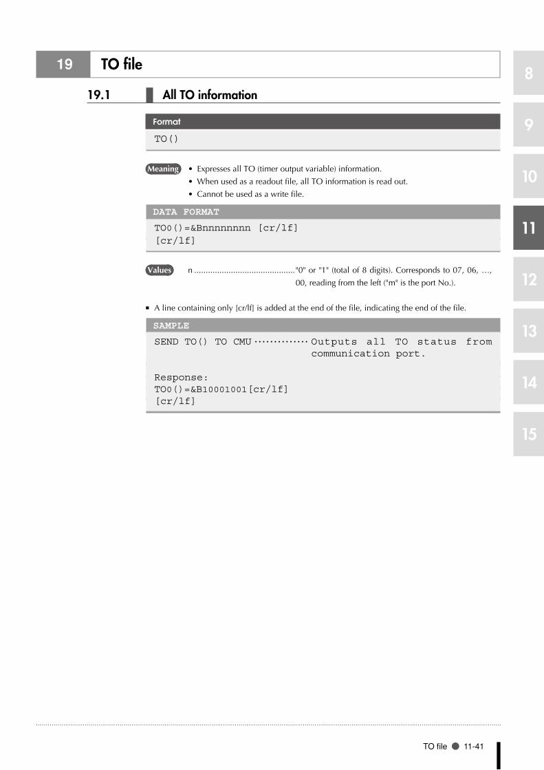
TO file 11-41
8
9
10
11
12
13
14
15
19 TO file
19.1 All TO information
Format
TO()
Meaning • ExpressesallTO(timeroutputvariable)information.
• Whenusedasareadoutfile,allTOinformationisreadout.
• Cannotbeusedasawritefile.
DATA FORMAT
TO0()=&Bnnnnnnnn [cr/lf][cr/lf]
Values n ............................................ "0" or "1" (total of 8 digits). Corresponds to 07, 06, …,
00, reading from the left ("m" is the port No.).
A line containing only [cr/lf] is added at the end of the file, indicating the end of the file. ■
SAMPLE
SEND TO() TO CMU ・・・・・・・・・・・・・・ Outputs all TO status from communication port.
Response:TO0()=&B10001001[cr/lf][cr/lf]

11-42 Chapter 11 Data file description
8
9
10
11
12
13
14
15
19.2 One TO port
Format
TO()
Meaning • ExpressesthestatusofoneTOport.
• Whenusedasareadoutfile,thespecifiedTOportstatusisreadout.
• Whenusedasawritefile,thevalueiswrittentothespecifiedTOport.
Readout file •
DATA FORMAT
TO0()=&Bnnnnnnnn[cr/lf]
Write file •
DATA FORMAT
&Bnnnnnnnn[cr/lf] or k[cr/lf]
Values n ............................................ "0" or "1" (total of 8 digits). Corresponds to 07, 06, …,
00, reading from the left ("m" is the port No.).
k ............................................Integer from 0 to 255
SAMPLE 1
SEND TO0() TO CMU ・・・・・・・・・・・・・ Outputs the TO0 port status from communication port.
Response:TO0()=&B00000000[cr/lf]
SAMPLE 2
SEND CMU TO TO0() ・・・・・・・・・・・・・ Inputs the TO0 port status from communication port.
&B00000111
Response:OK[cr/lf]

SI file 11-43
8
9
10
11
12
13
14
15
20 SI file
20.1 All SI information
Format
SI()
Meaning • ExpressesallSI(serialinputvariable)information.
• Whenusedasareadoutfile,allSIinformationisreadout.
• Cannotbeusedasawritefile.
DATA FORMAT
SI0()=&Bnnnnnnnn [cr/lf]SI1()=&Bnnnnnnnn [cr/lf] :SI27()=&Bnnnnnnnn [cr/lf][cr/lf]
Values n ............................................ "0" or "1" (total of 8 digits). Corresponds to m7, m6, …,
m0, reading from the left ("m" is the port No.).
A line containing only [cr/lf] is added at the end of the file, indicating the end of the file. ■
SAMPLE
SEND SI() TO CMU ・・・・・・・・・・・・・・ Outputs all SI status from communication port.
Response:SI0()=&B10001001[cr/lf]SI1()=&B00000010[cr/lf]SI2()=&B00000000[cr/lf]:SI7()=&B00000000[cr/lf]SI10()=&B00000000[cr/lf]SI11()=&B00000000[cr/lf]SI12()=&B00000000[cr/lf]:SI17()=&B00000000[cr/lf]SI20()=&B00000000[cr/lf]:SI26()=&B00000000[cr/lf]SI27()=&B00000000[cr/lf][cr/lf]

11-44 Chapter 11 Data file description
8
9
10
11
12
13
14
15
20.2 One SI port
Format
SIm()
Meaning • ExpressesthestatusofoneSIport.
• Whenusedasareadoutfile,thespecifiedSIportstatusisreadout.
• Cannotbeusedasawritefile.
DATA FORMAT
SIm()=&Bnnnnnnnn[cr/lf]
Values m ...........................................Port number: 0 to 7, 10 to 17, 20 to 27
n ............................................ "0" or "1" (total of 8 digits). Corresponds to m7, m6, …,
m0, reading from the left ("m" is the port No.).
SAMPLE
SEND SI5() TO CMU ・・・・・・・・・・・・・ Outputs the SI5 port status from communication port.
Response:SI5()=&B00000000[cr/lf]

SO file 11-45
8
9
10
11
12
13
14
15
21 SO file
21.1 All SO information
Format
SO()
Meaning • ExpressesallSO(serialoutputvariable)information.
• Whenusedasareadoutfile,allSOinformationisreadout.
• Cannotbeusedasawritefile.
DATA FORMAT
SO0()=&Bnnnnnnnn [cr/lf]SO1()=&Bnnnnnnnn [cr/lf] :SO27()=&Bnnnnnnnn [cr/lf][cr/lf]
Values n ............................................ "0" or "1" (total of 8 digits). Corresponds to m7, m6, …,
m0, reading from the left ("m" is the port No.).
A line containing only [cr/lf] is added at the end of the file, indicating the end of the file. ■
SAMPLE
SEND SO() TO CMU ・・・・・・・・・・・・・・ Outputs all SO status from communication port.
Response:SO0()=&B10001001[cr/lf]SO1()=&B00000010[cr/lf]SO2()=&B00000000[cr/lf]:SO7()=&B00000000[cr/lf]SO10()=&B00000000[cr/lf]SO11()=&B00000000[cr/lf]SO12()=&B00000000[cr/lf]:SO17()=&B00000000[cr/lf]SO20()=&B00000000[cr/lf]:SO26()=&B00000000[cr/lf]SO27()=&B00000000[cr/lf][cr/lf]

11-46 Chapter 11 Data file description
8
9
10
11
12
13
14
15
21.2 One SI port
Format
SOm()
Meaning • ExpressesthestatusofoneSOport.
• Whenusedasareadoutfile,thespecifiedSOportstatusisreadout.
• Whenusedasawritefile, thevalue iswritten to thespecifiedSOport.However,
writing to SO0() and SO1() is prohibited.
Readout file •
DATA FORMAT
SOm()=&Bnnnnnnnn[cr/lf]
Write file •
DATA FORMAT
&Bnnnnnnnn[cr/lf] or k[cr/lf]
Values m ...........................................Port number: 0 to 7, 10 to 17, 20 to 27
n ............................................ "0" or "1" (total of 8 digits). Corresponds to m7, m6, …,
m0, reading from the left ("m" is the port No.).
k ............................................Integer from 0 to 255
•Writing to SO0() and SO1() is prohibited. Only reference is permitted.
SAMPLE 1
SEND SO5() TO CMU ・・・・・・・・・・・・・ Outputs the SO5 port status from communication port.
Response:SO5()=&B00000000[cr/lf]
SAMPLE 2
SEND CMU TO SO5() ・・・・・・・・・・・・・ Inputs the SO5 port status from communication port.
&B00000111
Response:OK[cr/lf]
MEMO
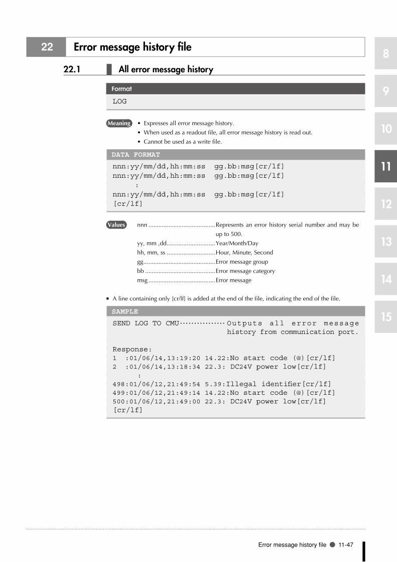
Error message history file 11-47
8
9
10
11
12
13
14
15
22 Error message history file
22.1 All error message history
Format
LOG
Meaning • Expressesallerrormessagehistory.
• Whenusedasareadoutfile,allerrormessagehistoryisreadout.
• Cannotbeusedasawritefile.
DATA FORMAT
nnn:yy/mm/dd,hh:mm:ss gg.bb:msg[cr/lf]nnn:yy/mm/dd,hh:mm:ss gg.bb:msg[cr/lf] :nnn:yy/mm/dd,hh:mm:ss gg.bb:msg[cr/lf][cr/lf]
Values nnn ........................................ Represents an error history serial number and may be
up to 500.
yy, mm ,dd .............................Year/Month/Day
hh, mm, ss .............................Hour, Minute, Second
gg ...........................................Error message group
bb ..........................................Error message category
msg ........................................Error message
A line containing only [cr/lf] is added at the end of the file, indicating the end of the file. ■
SAMPLE
SEND LOG TO CMU ・・・・・・・・・・・・・・・・ Outputs all error message history from communication port.
Response:1 :01/06/14,13:19:20 14.22:No start code (@)[cr/lf]2 :01/06/14,13:18:34 22.3: DC24V power low[cr/lf] :498:01/06/12,21:49:54 5.39:Illegal identifier[cr/lf]499:01/06/12,21:49:14 14.22:No start code (@)[cr/lf]500:01/06/12,21:49:00 22.3: DC24V power low[cr/lf][cr/lf]

11-48 Chapter 11 Data file description
8
9
10
11
12
13
14
15
23 Error Message History Details File
23.1 General error message history details
Format
LEX
Meaning • Displaysthegeneralerrormessagehistorydetails.
• ThisfilecannotbespecifiedasaWRITEfile.
DATA FORMAT
nnn.l:yy/mm/dd hh:mm:ss gg.bb:msg,A,N,L,P[cr/lf]nnn.l:M=x,y,z,r,a,b[cr/lf]nnn.l:S=x,y,z,r,a,b[cr/lf]
Values nnn ........................................ Represents an error history serial number and may be
up to 500.
l .............................................Output line number (max. of 3)
yy, mm ,dd .............................Year/Month/Day
hh, mm, ss .............................Hour, Minute, Second
gg ...........................................Error message group
bb ..........................................Error message category
msg ........................................Error message
A ............................................ AUTO operation execution status. 1: AUTO operation
in progress; 0: Other status.
N ...........................................Execution program name.
L ............................................Program's execution line No.
P ............................................No. of most recently referenced point.
M= ......................................... Indicates that all subsequent coordinates are main
robot coordinates.
S= .......................................... Indicates that all subsequent coordinates are sub robot
coordinates.
x,y,z,r,a,b ...............................Current position of each axis.
[cr/lf] ......................................CR code (0Dh) + LF code (0Ah).
A line containing only [cr/lf] is added at the end of the file, indicating the end of the file. ■
SAMPLE
SEND LEX to CMU ・・・・・・・・・・・・・・・・ Outputs the following general error message history details from the communication port.
Response:1 .1:01/06/14,13:19:20 14.22: No START code (@),0,TEST ,2,2500[cr/lf]1 .2:M= 23.80 23.59 0.00 0.00 0.00 0.00[cr/lf]1 .3:S= 48.20 47.99 0.00 0.00 0.00 0.00[cr/lf]2 .1:01/06/12,13:18:34 22.3: 24VDC low voltage,0,TEST ,6,2500[cr/lf]2 .2:M= 11568 23985 0.00 0.00 0.00 0.00[cr/lf]2 .3:S= 35693 12582 0.00 0.00 0.00 0.00]cr/lf] :500.1:01/06/12,21:49:00 22.3: 24VDC low voltage,0,TEST ,6,2500[cr/lf]500.2:M= 38.71 38.50 0.00 0.00 0.00 0.00[cr/lf]500.3:S= 51.48 51.27 0.00 0.00 0.00 0.00[cr/lf][cr/lf]
n NOTE
The "Error message history •details file" is available in the following software versions:
RCX240 Ver. 10.65 onwards
RCX22x Ver. 9.36 onwards
n NOTE
Error information is output •only for the connected robot.
n NOTE
Robot coordinates display •in pulse units for axes where an " incomplete return-to-origin" status exists. Robot coordinates also display in pulse units on SCARA robots where reference coordinates have not been specified.
Robot coordinates display •in mm/deg units for axes w h e re a " c o m p l e t e d return-to-origin" status exists.

Machine reference file 11-49
8
9
10
11
12
13
14
15
24 Machine reference file
24.1 All machine reference file
Format
MRF
Meaning • Expressesthemachinereferencedataobtainedafterrobotshaveperformedreturn-to-
origin and absolute search.
• Readsoutallmachinereferencedatawhenusedasareadoutfile.
• Cannotbeusedasawritefile.
DATA FORMAT
M1=nnn% M2=nnn% ・・・ nnn%[cr/lf]S1=nnn% S2=nnn% ・・・ nnn%[cr/lf][cr/lf]
Values nnn ........................................Integer from 0 to 100
M? ..........................................Indicate the main robot group axes.
S? ...........................................Indicate the sub robot group axes.
A line containing only [cr/lf] is added at the end of the file, indicating the end of the file. ■
SAMPLE
SEND MRF TO CMU ・・・・・・・・・・・・・・・・ Outputs all machine reference data from communication port.
Response:M1= 55% M2= 23% M3= 33% M4= 26%[cr/lf][cr/lf]

11-50 Chapter 11 Data file description
8
9
10
11
12
13
14
15
25 EOF file
25.1 EOF data
Format
EOF
Meaning • Thisfileisaspecialfileconsistingonlyofa^Z(=1Ah)code.Whentransmittingdata
to an external device through the communication port, the EOF data can be used to
add a ^Z code at the end of file.
• Whenusedasareadoutfile,^Z(=1Ah)isreadout.
• Cannotbeusedasawritefile.
DATA FORMAT
^Z (=1Ah)
SAMPLE
SEND PGM TO CMUSEND EOF TO CMU ・・・・・・・・・・・・・・・・ O u t p u t s E O F d a t a f r o m
communication port.
NAME=TEST1[cr/lf]A=1[cr/lf] :HALT[cr/lf][cr/lf]^Z
•A "^Z" code may be required at the end of the transmitted file, depending on the specifications
of the receiving device and application.MEMO

Serial port communication file 11-51
8
9
10
11
12
13
14
15
26 Serial port communication file
26.1 Serial port communication file
Format
CMU
Meaning • Expressestheserialcommunicationport.
• Dependsonthevariousdataformats.
SAMPLE
SEND PNT TO CMU ・・・・・・・・・・・・・・・・ Outputs all point data from communication port.
SEND CMU TO PNT ・・・・・・・・・・・・・・ Inputs all point data from communication port.

11-52 Chapter 11 Data file description
8
9
10
11
12
13
14
15
27 SIW file
27.1 All SIW
Format
SIW()
Meaning • ExpressesallSIW(serialwordinput)data.
• ReadsoutallSIWinformationinhexadecimaldigitwhenusedasareadoutfile.
• Cannotbeusedasawritefile.
DATA FORMAT
SIW( 0)=&Hnnnn [cr/lf]SIW( 1)=&Hnnnn [cr/lf] :SIW(15)=&Hnnnn [cr/lf][ cr/lf]
Values n ............................................0 to 9, A to F: 4 digits (hexadecimal)
A line containing only [cr/lf] is added at the end of the file, indicating the end of the file. ■
SAMPLE
SEND SIW() TO CMU ・・・・・・・・・・・・・ Outputs all SIW data from communication port.
Response:SIW(0)=&H1001[cr/lf]SIW(1)=&H0010[cr/lf]SIW(2)=&H0000[cr/lf] :SIW(15)=&H0000[cr/lf][cr/lf]
n NOTE
S IW i s ava i lab le f rom •sof tware vers ion 8 .08 onwards.

SIW file 11-53
8
9
10
11
12
13
14
15
27.2 One SIW data
Format
SIW(m)
Meaning • ExpressesoneSIWstatus.
• ReadsoutallSIWinformationinhexadecimaldigitwhenusedasareadoutfile.
• Cannotbeusedasawritefile.
DATA FORMAT
SIW(m)=&Hnnnn [cr/lf]
Values m ...........................................0 to 15
n ............................................0 to 9, A to F: 4 digits (hexadecimal)
SAMPLE
SEND SIW(5) TO CMU ・・・・・・・・・・・ O u t p u t s S I W ( 5 ) f r o m communication port.
Response:SIW(5)=&H1001[cr/lf]
n NOTE
S IW i s ava i lab le f rom •sof tware vers ion 8 .08 onwards.

11-54 Chapter 11 Data file description
8
9
10
11
12
13
14
15
28 SOW file
28.1 All SIW
Format
SOW()
Meaning • ExpressesallSOW(serialwordoutput)data.
• ReadsoutallSOWinformationinhexadecimaldigitwhenusedasareadoutfile.
• Cannotbeusedasawritefile.
DATA FORMAT
SOW( 0)=&Hnnnn [cr/lf]SOW( 1)=&Hnnnn [cr/lf] :SOW(15)=&Hnnnn [cr/lf][ cr/lf]
Values n ............................................0 to 9, A to F: 4 digits (hexadecimal)
A line containing only [cr/lf] is added at the end of the file, indicating the end of the file. ■
SAMPLE
SEND SOW() TO CMU ・・・・・・・・・・・・・ Outputs all SOW data from communication port.
Response:SOW(0)=&H1001[cr/lf]SOW(1)=&H0010[cr/lf]SOW(2)=&H0000[cr/lf] :SOW(15)=&H0000[cr/lf][cr/lf]
n NOTE
SOW is avai lable from •sof tware vers ion 8 .08 onwards.

SOW file 11-55
8
9
10
11
12
13
14
15
28.2 One SOW data
Format
SOW(m)
Meaning • ExpressesoneSOWstatus.
• Whenusedasareadoutfile,thespecifiedSOWportstatusisreadout.
• Whenusedasawrite file, thevalue iswritten to thespecifiedSOW.However,
writing to SOW0() and SOW1() is prohibited.
Readout file •
DATA FORMAT
SOW(m)=&Hnnnn [cr/lf]
Write file •
DATA FORMAT
&Hnnnn
Values m ...........................................2 to 15
n ............................................0 to 9, A to F: 4 digits (hexadecimal)
SAMPLE 1
SEND SOW(5) TO CMU ・・・・・・・・・・・ O u t p u t s S O W ( 5 ) f r o m communication port.
Response:SOW(5)=&H1001[cr/lf]
SAMPLE 2
SEND CMU TO SOW(5) ・・・・・・・・・・・ I n p u t t o S O W ( 5 ) f r o m communication port.
&H1001
Response:OK[cr/lf]
n NOTE
SOW is avai lable from •sof tware vers ion 8 .08 onwards.

11-56 Chapter 11 Data file description
8
9
10
11
12
13
14
15
29 Ethernet port communication file
29.1 Ethernet port communication file
Format
ETH
Meaning • ExpressestheEthernetport.
• Dependsonthevariousdataformats.
SAMPLE
SEND PNT TO ETH ・・・・・・・・・・・・・・・・ Outputs all point data from the Ethernet port.
SEND ETH TO PNT ・・・・・・・・・・・・・・・・ Inputs all point data from the Ethernet port.
n NOTE
ETH i s ava i lab le f rom •sof tware vers ion 8 .22 onwards.

Chapter 12
User program examples
1 1 Basic operation.......................................12-1
2 2 Application .............................................12-8


Basic operation 12-1
8
9
10
11
12
13
14
15
1 Basic operation
1.1 Directly writing point data in program
Overview ■
The robot arm can be moved by PTP (point-to-point) motion by directly specifying point data in the
program.
Processing flow
300.00 300.00 50.00 90.00 0.00 0.00 PTP movement
300.00 100.00 0.00 0.00 0.00 0.00 PTP movement
200.00 200.00 10.00 -90.00 0.00 0.00 PTP movement
START
STOP
33C01-R7-00
SAMPLE
MOVE P, 300.00 300.00 50.00 90.00 0.00 0.00MOVE P, 300.00 100.00 0.00 0.00 0.00 0.00MOVE P, 200.00 200.00 10.00 -90.00 0.00 0.00HALT

12-2 Chapter 12 User program examples
8
9
10
11
12
13
14
15
1.2 Using point numbers
Overview ■
Coordinate data can be specified by using point numbers in a program. Coordinate data should be
entered beforehand in "MANUAL>POINT" mode, for example as shown below.
POINT DATA
P0= 0.00 0.00 0.00 0.00 0.00 0.00P1= 100.00 0.00 150.00 30.00 0.00 0.00P2= 0.00 100.00 50.00 0.00 0.00 0.00P3= 300.00 300.00 0.00 0.00 0.00 0.00P4= 300.00 100.00 100.00 90.00 0.00 0.00P5= 200.00 200.00 0.00 0.00 0.00 0.00
Processing flow
PTP movement to P0
PTP movement to P1
PTP movement to P2
PTP movement to P3
PTP movement to P4
PTP movement to P5
START
STOP
33C02-R7-00
SAMPLE 1
MOVE P,P0MOVE P,P1MOVE P,P2MOVE P,P3MOVE P,P4MOVE P,P5HALT
SAMPLE 2
FOR J=0 TO 5 MOVE P,P[J]NEXT JHALT
Although the same operation is executed by both SAMPLE 1 and SAMPLE 2, the program can be
shortened by using point Nos. and the FOR statement.
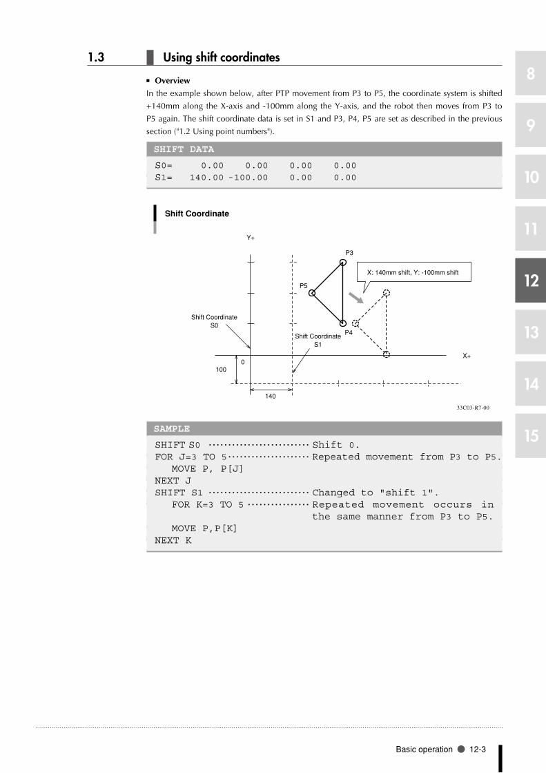
Basic operation 12-3
8
9
10
11
12
13
14
15
1.3 Using shift coordinates
Overview ■
In the example shown below, after PTP movement from P3 to P5, the coordinate system is shifted
+140mm along the X-axis and -100mm along the Y-axis, and the robot then moves from P3 to
P5 again. The shift coordinate data is set in S1 and P3, P4, P5 are set as described in the previous
section ("1.2 Using point numbers").
SHIFT DATA
S0= 0.00 0.00 0.00 0.00S1= 140.00 -100.00 0.00 0.00
Shift Coordinate
P3
X: 140mm shift, Y: -100mm shift
P5
P4
�
Y+
X+�
Shift CoordinateS0
Shift CoordinateS1
0
140
100
33C03-R7-00
SAMPLE
SHIFT S0 ・・・・・・・・・・・・・・・・・・・・・・・・・・ Shift 0.FOR J=3 TO 5 ・・・・・・・・・・・・・・・・・・・・・ Repeated movement from P3 to P5. MOVE P, P[J]NEXT JSHIFT S1 ・・・・・・・・・・・・・・・・・・・・・・・・・・ Changed to "shift 1". FOR K=3 TO 5 ・・・・・・・・・・・・・・・・ Repeated movement occurs in
the same manner from P3 to P5. MOVE P,P[K]NEXT K

12-4 Chapter 12 User program examples
8
9
10
11
12
13
14
15
1.4 Palletizing
1.4.1 Calculating point coordinates
Overview ■
Repetitive movement between a fixed work supply position P0 and each of the equally spaced
points on a pallet can be performed with the following program.
In the drawing below, points N1 to N20 are on Cartesian coordinates, consisting of 5 points
positioned at a 50mm pitch in the X-axis direction and 4 points at a 25mm pitch in the Y-axis
direction. The robot arm moves from point to point in the order of P0-N1-P0-N2...N5-P0-N6-P0...
while repeatedly moving back and forth between point P0 and each pallet.
POINT DATA
Work supply position: P0= 0.0 0.0 0.0 0.0 0.0 0.0X-axis pitch: P10= 50.0 0.0 0.0 0.0 0.0 0.0Y-axis pitch: P20= 0.0 25.0 0.0 0.0 0.0 0.0N1 position: P1 = 100.0 50.0 0.0 0.0 0.0 0.0
Calculating point coordinates
X+�
�
N16 N17 N18 N19 N20
N11 N12 N13 N14 N15
N6 N7 N8 N9 N10
N1 N2 N3 N4 N5
50
25
P0
Y+
33C04-R7-00
Processing flow
START
Movement to supply position.
Movement to P100
P100 is shifted by the pitch amount
in the X-direction.
P200=P1
P100=P1
Repeat 5 times
Repeat 4 times
Movement to P0
Movement to P100
P100=P100+P10
STOP
P200=P200+P20
P100=P200
P1 coordinates are input at P200.
P1 coordinates are input at P100.
Movement to P200
P200 is shifted by the pitch amount
in the Y-direction.
31C05-R7-00

Basic operation 12-5
8
9
10
11
12
13
14
15
SAMPLE
P100=P1P200=P1FOR J=1 TO 4 FOR K=1 TO 5 MOVE P,P0 MOVE P,P100 P100=P100+P10 NEXT K P200=P200+P20 P100=P200NEXT J

12-6 Chapter 12 User program examples
8
9
10
11
12
13
14
15
1.4.2 Utilizing pallet movement
Overview ■
Repetitive movement between a fixed work supply position P0 and each of the equally spaced
points on a pallet can be performed with the following program. In the drawing below, points
N1 to N24 are on Cartesian coordinates, consisting of 3 points positioned at a 50mm pitch in the
X-axis direction, 4 points at a 50mm pitch in the Y-axis direction, and 2 points at 100mm pitch in
the Z-axis direction. The robot arm moves from point to point in the order of P0-N1-P0-N2...-N5-
P0-N6... while repeatedly moving back and forth between point P0 and each pallet.
POINT DATA
Work supply position: P0= 0.00 0.00 100.00 0.00 0.00 0.00Pallet definition: PL0 (P3996 to P4000 are used)NX= 3NY= 4NZ= 2P3996= 100.00 50.00 100.00 0.00 0.00 0.00P3997= 200.00 50.00 100.00 0.00 0.00 0.00P3998= 100.00 200.00 100.00 0.00 0.00 0.00P3999= 200.00 200.00 100.00 0.00 0.00 0.00P4000= 100.00 50.00 200.00 0.00 0.00 0.00
Utilizing pallet movement
P4000
P3998 P3999
P3997P3996
NZ
NX
NY
P0
33C06-R7-00
Processing flow
START
Movement to P0
Pallet movementRepeat 24 times
STOP
Movement to supply position (P0).
Repeated for points N1 to N24.
33C07-R7-00
SAMPLE
FOR I=1 TO 24 ・・・・・・・・・・・・・・・・・・・ Repeated for I = 1 to 24. MOVE P,P0,Z=0.00 ・・・・・・・・・・ Movement to supply position. PMOVE (0,I),Z=0.00 ・・・・・・・ Movement to pallet point.NEXT IMOVE P,P0,Z=0.00

Basic operation 12-7
8
9
10
11
12
13
14
15
1.5 DI/DO (digital input and output) operation
Overview ■
The following example shows general-purpose signal input and output operations through the STD.
Processing flow
Wait until DI2( ) is all at "0".
Set all of DO2 ( ) to "1".
Wait 1 second.
Wait until DI2 (0) is at "1".
END
N
DI2 (1)="1"?
N=1
N>20
Set all of DO2 ( ) to “0”.
Wait 0.5 seconds
N=N+1
Set DO2 (7, 6, 1, 0) to "1".
Wait 2 seconds
Set all of DO2 ( ) to "0".
Y
Y
N
START
Wait until DI20 to DI27 become "0".
DO20 to DO27 become "1".
Wait until DI20 becomes "1".
• DO processing ends if DI2(1) is "1".
• Repeated until N=20 if DI2(1) is "0".
"1" is assigned to "N".
33C08-R7-00
SAMPLE
WAIT DI2( )=0 ・・・・・・・・・・・・・・・・・・・ Wait until DI20 to DI27 become "0".DO2( )=&B11111111 ・・・・・・・・・・・・・・ DO20 to DO27 become "1".DELAY 1000WAIT DI2(0)=1 ・・・・・・・・・・・・・・・・・・・ Wait until DI21 becomes "1".N=1*LOOP1:IF DI2(1)=1 THEN *PROGEND ・・・ Jumps to *PROGEND if DI21 = 1.IF N>20 THEN *ALLEND ・・・・・・・・ Ended in N > 20 (jumps to *ALLEND).DO2( )=0 ・・・・・・・・・・・・・・・・・・・・・・・・・・ DO20 to DO27 become "0".DELAY 500N=N+1GOTO *LOOP1 ・・・・・・・・・・・・・・・・・・・・・・ Loop is repeated.’END ROUTINE*PROGEND: ・・・・・・・・・・・・・・・・・・・・・・・・・ End processing.DO2(7,6,1,0)=&B1111 ・・・・・・・・・・・ Set DO27, 26, 21, 20 to "1".DELAY 2000 ・・・・・・・・・・・・・・・・・・・・・・・・ Wait 2 secondsDO2( )=0 ・・・・・・・・・・・・・・・・・・・・・・・・・・ Set DO20 to "0".*ALLEND:HALT

12-8 Chapter 12 User program examples
8
9
10
11
12
13
14
15
2 Application
2.1 Pick and place between 2 points
Overview ■
The following is an example for picking up a part at point A and placing it at point B.
Pick and place between 2 points
0
Z
P3
P1
P4
P2
Point A Point B
50mm
30mm
33C09-R7-00
Precondition ■
1. Set the robot movement path.
• Movementpath:P3→P1→P3→P4→P2→P4
• LocateP3andP4respectivelyataposition50mmaboveP1andP2andsettheP1andP2
positions by teaching.
2. I/O signal
DO (20) Chuck (gripper) open/close = 0: open, 1: close
• A0.1secondwaittimeissetduringchuckopenandclose.
SAMPLE: When calculating to find P3 and P4
P3=P1 ・・・・・・・・・・・・・・・・・・・・・・・・・・ P1 coordinates are assigned to P3. P4=P2 ・・・・・・・・・・・・・・・・・・・・・・・・・・ P2 coordinates are assigned to P4. LOCZ(P3)=LOCZ(P3)-50.0 ・・・・ P3 is shifted 50mm in Z UP direction. LOCZ(P4)=LOCZ(P4)-50.0 ・・・・ P4 is shifted 50mm in Z UP direction. MOVE P,P3 GOSUB *OPEN MOVE P,P1 GOSUB *CLOSE MOVE P,P3 MOVE P,P4 MOVE P,P2 GOSUB *OPEN MOVE P,P4 HALT*OPEN: ・・・・・・・・・・・・・・・・・・・・・・・・・・ Chuck OPEN routine. DO2(0)=0 DELAY 100 RETURN*CLOSE: ・・・・・・・・・・・・・・・・・・・・・・・・・・ Chuck CLOSE routine. DO2(0)=1 DELAY 100 RETURN

Application 12-9
8
9
10
11
12
13
14
15
SAMPLE: When using arch motion
P4=P2 ・・・・・・・・・・・・・・・・・・・・・・・・・・ P2 coordinates are assigned to P4. LOCZ(P4)=LOCZ(P4)-50.0 ・・・・ P4 is shifted 50mm in Z UP direction. GOSUB *OPEN MOVE P,P1,Z=30.0 ・・・・・・・・・・ Arch motion at Z = 30mm. GOSUB *CLOSE MOVE P,P2,Z=30.0 ・・・・・・・・・・ Arch motion at Z = 30mm. GOSUB *OPEN MOVE P,P4 HALT*OPEN: ・・・・・・・・・・・・・・・・・・・・・・・・・・ Chuck OPEN routine. DO2(0)=0 DELAY 100 RETURN*CLOSE: ・・・・・・・・・・・・・・・・・・・・・・・・・・ Chuck CLOSE routine. DO2(0)=1 DELAY 100 RETURN

12-10 Chapter 12 User program examples
8
9
10
11
12
13
14
15
2.2 Palletizing
Overview ■
The following is an example for picking up parts supplied from the parts feeder and placing them on
a pallet on the conveyor. The pallet is ejected when full.
Palletizing
P1: Pallet reference position
Robot
Z
0
50mm
P1 P0
P0: Part supply position
Parts feeder
33C10-R7-00
Precondition ■
1. I/O signal
DI (30) Component detection sensor 1: Parts are suppliedDI (31) Pallet sensor 1: Pallet is loaded
DO (30) Robot hand open/close 0: Open / 1: CloseDO (31) Pallet eject 1: Eject
Robot hand open/close time is 0.1 second and pallet eject time is 0.5 seconds.
2. The points below should be input beforehand as point data.
P0 Part supply positionP1 Pallet reference positionP10 X direction pitchP11 Y direction pitch
3. Vertical movement is performed to a position Z=50mm above the pallet and parts feeder.

Application 12-11
8
9
10
11
12
13
14
15
SAMPLE 1: When point is calculated
WHILE -1 ・・・・・・・・・・・・・・・・・・・・・・・・・・ All repeated (-1 is always TRUE).FOR A=0 TO 2FOR B=0 TO 2 WAIT DI(31)=1 ・・・・・・・・・・・・・・・ Wait until a pallet "present"
status occurs. WAIT DI(30)=1 ・・・・・・・・・・・・・・・ Wait until the supplied component
"present" status occurs. DO(30)=0 ・・・・・・・・・・・・・・・・・・・・・・・ Robot hand OPENS. DELAY 100 MOVE P,P0,Z=50.0 ・・・・・・・・・・ Movement to supply position. DO(30)=1 ・・・・・・・・・・・・・・・・・・・・・・・ Robot hand CLOSES. DELAY 100 P100=P1+P10*B+P11*A ・・・・・・ Next point is calculated. MOVE P,P100,Z=50.0 ・・・・・・・ Movement to calculated point. DO(30)=0 ・・・・・・・・・・・・・・・・・・・・・・・ Robot hand OPENS. DELAY 100NEXTNEXTDRIVE (3,0) ・・・・・・・・・・・・・・・・・・・・・・ Only Z-axis moves to 0.DO(31)=1 ・・・・・・・・・・・・・・・・・・・・・・・・・・ Pallet is ejected.DELAY 500DO(31)=0 WEND ・・・・・・・・・・・・・・・・・・・・・・・・・・ Loop is repeated.HALT
SAMPLE 2: When using the palletizing function
* Precondition: Must be defined at pallet "0".WHILE -1 ・・・・・・・・・・・・・・・・・・・・・・・・・・ All repeated.FOR A=1 TO 9 WAIT DI(31)=1 ・・・・・・・・・・・・・・・ Wait until a pallet "present"
status occurs. WAIT DI(30)=1 ・・・・・・・・・・・・・・・ Wait until the supplied component
"present" status occurs. DO(30)=0 ・・・・・・・・・・・・・・・・・・・・・・・ Robot hand OPENS. DELAY 100 MOVE P,P0,Z=50.0 ・・・・・・・・・・ Movement to supply position. DO(30)=1 ・・・・・・・・・・・・・・・・・・・・・・・ Robot hand CLOSES. DELAY 100 PMOVE(0,A),Z=50.0 ・・・・・・・・・ Movement to pallet point. DO(30)=0 ・・・・・・・・・・・・・・・・・・・・・・・ Robot hand OPENS. DELAY 100NEXTDRIVE(3,0) ・・・・・・・・・・・・・・・・・・・・・・・・ Only Z-axis moves to 0.DO(31)=1 Pallet is ejected.DELAY 500DO(31)=0WEND ・・・・・・・・・・・・・・・・・・・・・・・・・・ Loop is repeated.HALT
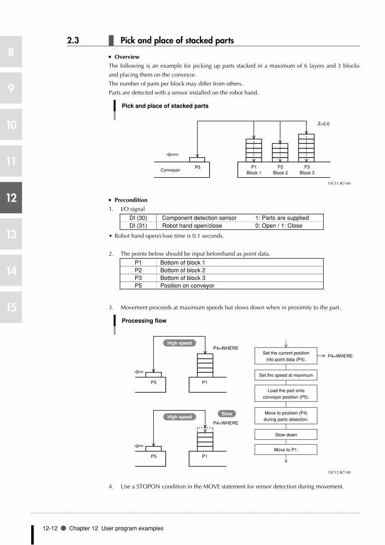
12-12 Chapter 12 User program examples
8
9
10
11
12
13
14
15
2.3 Pick and place of stacked parts
Overview ■
The following is an example for picking up parts stacked in a maximum of 6 layers and 3 blocks
and placing them on the conveyor.
The number of parts per block may differ from others.
Parts are detected with a sensor installed on the robot hand.
Pick and place of stacked parts
ConveyorP5 P1
Block 1P2
Block 2P3
Block 3
Z=0.0
33C11-R7-00
Precondition ■
1. I/O signal
DI (30) Component detection sensor 1: Parts are suppliedDI (31) Robot hand open/close 0: Open / 1: Close
• Robothandopen/closetimeis0.1seconds.
2. The points below should be input beforehand as point data.
P1 Bottom of block 1P2 Bottom of block 2P3 Bottom of block 3P5 Position on conveyor
3. Movement proceeds at maximum speeds but slows down when in proximity to the part.
Processing flow
P5 P1
P5 P1
P4=WHERE
P4=WHERE
High speed
High speedSlow
Set the current positioninto point data (P4).
P4=WHERE
Set the speed at maximum
Load the part ontoconveyor position (P5).
Move to position (P4)during parts detection.
Move to P1.
Slow down
33C12-R7-00
4. Use a STOPON condition in the MOVE statement for sensor detection during movement.

Application 12-13
8
9
10
11
12
13
14
15
SAMPLE
FOR A=1 TO 3SPEED 100GOSUB *OPENP6=P[A]LOCZ(P6)=0.00MOVE P,P6,Z=0.0WHILE -1 SPEED 20 MOVE P,P[A],STOPON DI3(0)=1 IF DI3(0)=0 THEN *L1 ’SENSOR ON P4=JTOXY(WHERE) GOSUB *CLOSE SPEED 100 MOVE P,P5,Z=0.0 GOSUB *OPEN MOVE P,P4,Z=0.0WEND*L1: ’SENSOR OFFNEXT ASPEED 100DRIVE (3,0)HALT*OPEN:DO3(0)=0DELAY 100RETURN*CLOSE:DO3(0)=1DELAY 100RETURN

12-14 Chapter 12 User program examples
8
9
10
11
12
13
14
15
2.4 Parts inspection (Multi-tasking example)
Overview ■
One robot is used to inspect two different parts and sort them according to the OK/NG results.
The robot picks up the part at point A and moves it to the testing device at point B. The testing
device checks the part and sends it to point C if OK or to point D if NG.
The part at point A’ is picked up and moved to the testing device at point B' in the same way. The
testing device checks the part and sends it to point C’ if OK or to point D’ if NG.
It is assumed that 10 to 15 seconds are required for the testing device to issue the OK/NG results.
Parts inspection (Multi-tasking example)
A
P1
B
P2
C
P3
D
P4
A’
P11
B’
P12
C’
P13
D’
P14
Parts supply Testing device OK NG
33C13-R7-00
■ Precondition
1. I/O signal
I/O signal
Testing device 2 start (0.1 second)DO3
1: Start *1
7 6 5 4 3 2 1 0
Testing device 1 test completed *3
Testing device 1 OK/NG signalPart supply 1Part 1 OKPart 1 NG
DI2 7 6 5 4 3 2 1 0
DI37 6 5 4 3 2 1 0
Testing device 1 start (0.1 second) Robot chuck open/close
DO21: Start *1
0: Open / 1: Close *2
7 6 5 4 3 2 1 0
Testing device 2 test completed *3
Testing device 2 OK/NG signalPart supply 2Part 2 OKPart 2 NG
33C14-R7-00
2. The main task (task 1) is used to test part 1 and the subtask (task 2) is used to test part 2.
3. An exclusive control flag is used to allow other tasks to run while waiting for the test
completion signal from the testing device.
FLAG1 0: Executing Task 1 (Task 2 execution enabled)1: Task 1 standby (Task 2 execution disabled)
FLAG2 0: Executing Task 2 (Task 1 execution enabled)1: Task 2 standby (Task 1 execution disabled)
n NOTE
*1: As the start s ignal, •s u p p l y a 0 . 1 s e c o n d pulse signal to the testing device.
0.1 seconds
ONOFF
*2: Chuck open and close •time is 0.1 seconds.
* 3 : E a c h t i m e a t e s t •i s f i n i s h e d , t h e t e s t completion signal and OK/NG signal are sent from the testing device. After test ing, the test completion signal turns ON (=1), and the OK/ NG signal turns ON (=1) when the result is OK and turns OFF (=0) when NG.

Application 12-15
8
9
10
11
12
13
14
15
4. Flow chart
Processing flow
Task 2 busy?
Exclusive control flag set
Task 2 busy?
START
Exclusive control flag reset
Subtask start
Part 1 supplied?
Chuck open
Move to parts supply position P1
Chuck close
Move to testing device 1
Chuck open
Move upward 10000 pulses
Exclusive control flag reset
Testing device 1 start
Test completed?
Exclusive control flag set
Move to testing device 1
Chuck close
Part OK?
OK parts?
Move to OK parts position
Chuck open
Move upward 10000 pulses
Exclusive control flag reset
NG parts?
FLAG1=0 FLAG2=0
Move to NG parts position
FLAG1=0
FLAG1=1
FLAG1=0
FLAG1=1
N
Y
Y
N
Y
N
Y
N
Y
Y
Y
N
Y
N
N
33C15-R7-00
Task 2 (subtask) runs in the same flow.

12-16 Chapter 12 User program examples
8
9
10
11
12
13
14
15
Program example ■
SAMPLE
<Main task>FLAG1=0FLAG2=0UPPOS=0.0START *S1,T2*L1:WAIT DI2(2)=1WAIT FLAG2=0FLAG1=1GOSUB *OPENMOVE P,P1,Z=UPPOSGOSUB *CLOSEMOVE P,P2,Z=UPPOSGOSUB *OPENDRIVEI (3,-10000)FLAG1=0DO2(0)=1DELAY 100DO2(0)=0WAIT DI2(0)=1WAIT FLAG2=0FLAG1=1MOVE P,P2,Z=UPPOSGOSUB *CLOSEIF DI2(1)=1 THEN'GOODWAIT DI4(2)=0MOVE P,P3,Z=UPPOSELSE'NGWAIT DI2(4)=0MOVE P,P4,Z=UPPOSENDIFGOSUB *OPENDRIVEI (3,-10000)FLAG1=0GOTO *L1*OPEN:DO2(1)=0DELAY 100RETURN*CLOSE:DO2(1)=1DELAY 100RETURN
Subtask Start
Part supply standbyOther tasks waiting for standby status.Exclusive control flag setChuck openMove to part supply positionChuck closeMove to testing deviceChuck openMove Z-axis upward Z 10,000 pulsesExclusive control flag resetTesting device start
Test completion standbyTask completion standbyExclusive control flag setMove to testing deviceChuck closeTest
Part movement standbyMove to OK parts position
Part movement standbyMove to NG parts position
Chuck openMove Z-axis upward Z 10,000 pulsesExclusive control flag reset
<Subtask>
*S1:WAIT DI3(2)=1WAIT FLAG1=0FLAG2=1GOSUB *OPENMOVE P,P11,Z=UPPOSGOSUB *CLOSEMOVE P,P12,Z=UPPOSGOSUB *OPENDRIVEI (3,-10000)FLAG2=0DO3(0)=1DELAY 100DO3(0)=0WAIT DI3(0)=1WAIT FLAG1=0FLAG2=1MOVE P,P12,Z=UPPOSGOSUB *CLOSEIF DI3(1)=1 THEN'GOODWAIT DI3(3)=0MOVE P,P13,Z=UPPOSELSE'NGWAIT DI3(4)=0MOVE P,P14,Z=UPPOSENDIFGOSUB *OPENDRIVEI (3,-10000)FLAG2=0GOTO *S1

Application 12-17
8
9
10
11
12
13
14
15
2.5 Sealing
Overview ■
This section shows an example of the parts sealing operation.
Sealing
P0 P1
P2
P3
P4P5
P6 P7
10mm
20mm
33C16-R7-00
Precondition ■
1. I/O signal
DO (20) Valve open/close 1: Open / 0: Close
2. Set P0 to P7 by teaching.
SAMPLE
MOVE P,P0,Z=0SPEED 40PATH SET ・・・・・・・・・・・・・・・・・・・・・・・・・ Start of path settingPATH L,P1,DO(20)[email protected] ・・・・ Start of coating
at 10 mm position
Path setting(Robot does not operate.)
PATH L,P2PATH C,P3,P4PATH L,P5PATH L,P6,S=30PATH L,P7,DO(20)[email protected] ・・・・ End of coating at
20 mm positionPATH END ・・・・・・・・・・・・・・・・・・・・・・・・・・ End of path settingPATH START ・・・・・・・・・・・・・・・・・・・・・・・・ Execute PATH motion (Robot
starts from P0 and stops at P7.)HALT

12-18 Chapter 12 User program examples
8
9
10
11
12
13
14
15
2.6 Connection to an external device through RS-232C (example 1)
Overview ■
Point data can be written in a program by using an external device connected to the RCX series
controller via the RS-232C port.
Precondition ■
1. Input to the external device from the controller
SDATA/X/Y [cr/lf]
2. Output to the controller from the external device
POINT DATA
P10= 156.42 243.91 0.00 0.00 0.00 0.00 [cr/lf]
SAMPLE
’INIT VCMD$="SDATA/X/Y" P0= 0.00 0.00 0.00 0.00 0.00 0.00’MAIN ROUTINE MOVE P, P0*ST: SEND VCMD$ TO CMU SEND CMU TO P10 MOVE P, P10GOTO *ST
•"SEND xxx TO CMU" outputs the contents specified by "xxx" through the RS-232C.
•"SENDCMUTOxxx"sendsdataintothefilesspecifiedby"xxx"throughtheRS-232C.
n NOTE
[cr/lf] indicates CR code •(=0Dh) + LF code (=0Ah).
MEMO

Application 12-19
8
9
10
11
12
13
14
15
2.7 Connection to an external device through RS-232C (example 2)
Overview ■
Point data can be created from the desired character strings and written in a program by using an
external device connected to the RCX series controller via the RS-232C port.
Precondition ■
1. Input to the external device from the controller
SDATA/X/Y [cr/lf]
2. Output to the controller from the external device
X=156.42, Y=243.91 [cr/lf]
•"SEND xxx TO CMU" outputs the contents specified by "xxx" through the RS-232C.
•"SENDCMUTOxxx"sendsdataintothefilesspecifiedby"xxx"throughtheRS-232C.
•TheLEN()functionobtainsthelengthofthecharacterstring.
•TheMID$()functionobtainsthespecifiedcharacterstringfromamongthecharacterstrings.
•TheVAL()functionobtainsthevaluefromthecharacterstring.
n NOTE
[cr/lf] indicates CR code •(=0Dh) + LF code (=0Ah).
MEMO

12-20 Chapter 12 User program examples
8
9
10
11
12
13
14
15
SAMPLE
’INT VCMD$="SDATA/X/Y" VIN$="" VX$="" VY$="" P0= 0.00 0.00 0.00 0.00 0.00 0.00 P11= 100.00 100.00 0.00 0.00 0.00 0.00’MAIN ROUTINE MOVE P, P0*ST: SEND VCMD$ TO CMU SEND CMU TO VIN$ I=1 VMAX=LEN(VIN$)*LOOP: IF I>VMAX THEN GOTO *E_LOOP C$=MID$(VIN$,I ,1) IF C$="X" THEN I=I+2 J=I*X_LOOP: C$=MID$(VIN$, J, 1) IF C$="," THEN*X1_LP: L=J-I VX$=MID$(VIN$, I, L) I=J+1 GOTO *LOOP ENDIF J=J+1 IF J>VMAX THEN GOTO *X1_LP GOTO *X_LOOP ENDIF IF C$="Y" THEN I=I+2 J=I*Y_LOOP: C$=MID$(VIN$, J, 1) IF C$=","THEN*Y1_LP: L=J-I VY$=MID$(VIN$, I, L) I=J+1 GOTO *LOOP ENDIF J=J+1 IF J>VMAX THEN GOTO *Y1_LP GOTO *Y_LOOP END IF I=I+1 GOTO *LOOP*E_LOOP: WX=VAL(VX$) WY=VAL(VY$) LOCX(P11)=WX LOCY(P11)=WY MOVE P, P11GOTO *ST

Chapter 13
Online commands
1 1 Online Command List ............................13-1
2 2 Key operation .........................................13-6
3 3 Utility operation ..................................... 13-12
4 4 Data handling ....................................... 13-24
5 5 Executing the robot language independently ... 13-44
6 6 Control codes ....................................... 13-46


Online Command List 13-1
8
9
10
11
12
13
14
15
1 Online Command List
Online commands can be used to operate the controller via an RS-232C interface or via an Ethernet
(option).
This chapter explains the online commands which can be used. For details regarding the RS-232C
connection method, refer to the "RCX Controller User's Manual". For details regarding Ethernet,
refer to the "RCX Series Ethernet Manual".
About termination codes
During data transmission, the controller adds the following codes to the end of a line of transmission data.
RS-232C •
•CR(0Dh)andLF(0Ah)areaddedtotheendofthelinewhenthe"Terminationcode"parameter
of communication parameters is set to "CRLF".
• CR(0Dh)isaddedtotheendofthelinewhenthe"Terminationcode"parameterof
communication parameters is set to "CR".
Ethernet (option) •
• CR(0Dh)andLF(0Ah)areaddedtotheendoftheline.
When data is received, then the data up to CR (0Dh) is treated as one line regardless of the
"Termination code" parameter setting, so LF (0Ah) is ignored.
The termination code is expressed as [cr/lf] in the detailed description of each online command in
"12.2 Key operation" onwards.
1.1 Online command list: Function specific
Key operation
Operation type Command Option Condition
Change mode AUTO mode AUTO 3 PROGRAM mode PROGRAM MANUAL mode MANUAL SYSTEM mode SYSTEM Program Reset program RESET 4 Execute program RUN Execute one line STEP Skip one line SKIP Execute to next line NEXT Stop program STOP 2Set break point BREAK m, n (m: break point No., n: line) 4Switch execution task CHGTSK 3Change manual speed Main robot MSPEED k (k : 1-100) 3 Sub robot MSPEED2 k (k : 1-100) Move to absolute reset position Main robot ABSADJ k, 0 or k, 1 (k : 1-6) 3 Sub robot ABSADJ2 k, 0 or k, 1 (k : 1-6) Absolute reset on each axis Main robot ABSRESET k (k : 1-6) Sub robot ABSRESET2 k (k : 1-6) Return-to-origin Main robot ORGRTN k (k : 1-6) 3 Sub robot ORGRTN2 k (k : 1-6)Manual movement (inching) Main robot INCH k+ or k- (k : X, Y, Z, R, A, B) 3 Sub robot INCH2 k+ or k- (k : X, Y, Z, R, A, B)Manual movement (jog) Main robot JOG k+ or k- (k : X, Y, Z, R, A, B) 3 Sub robot JOG2 k+ or k- (k : X, Y, Z, R, A, B)
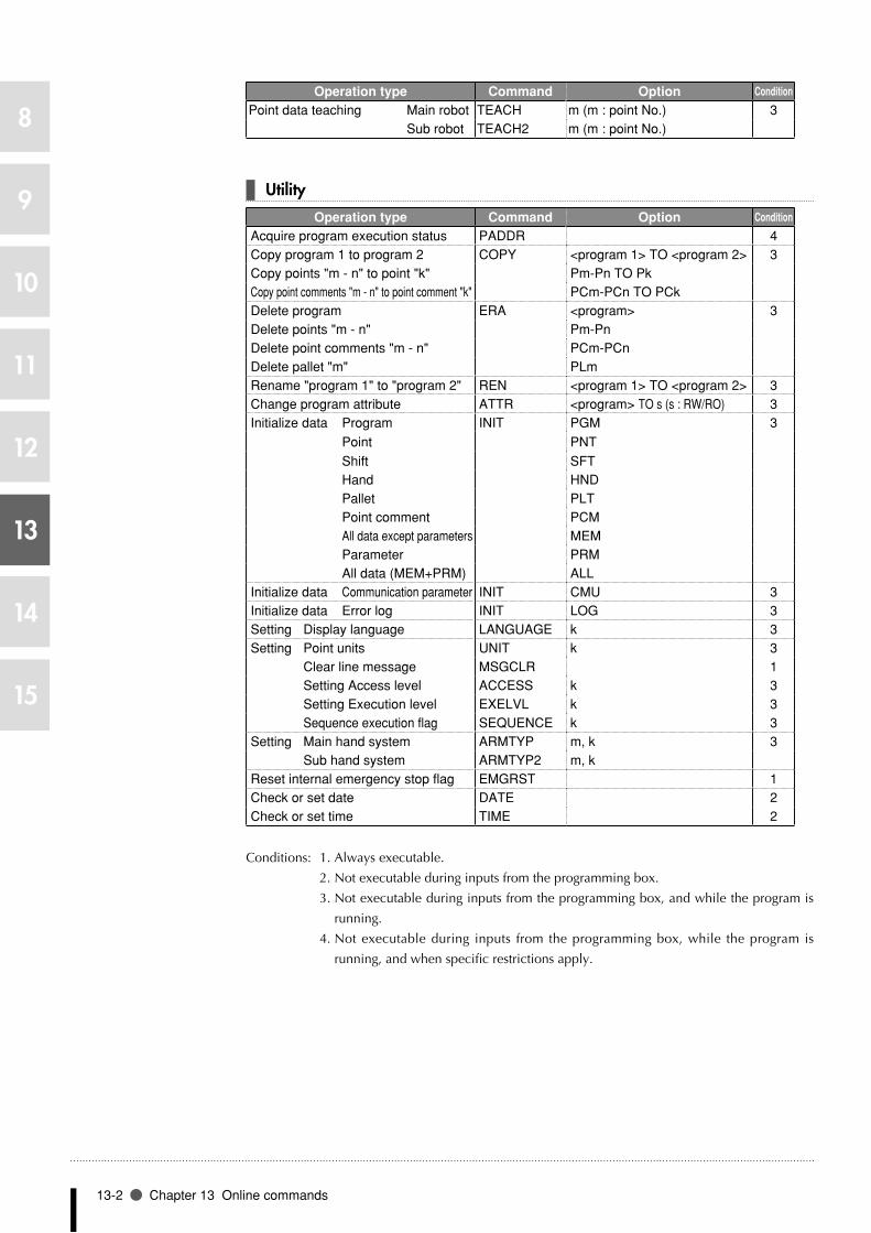
13-2 Chapter 13 Online commands
8
9
10
11
12
13
14
15
Operation type Command Option Condition
Point data teaching Main robot TEACH m (m : point No.) 3 Sub robot TEACH2 m (m : point No.)
Utility
Operation type Command Option Condition
Acquire program execution status PADDR 4Copy program 1 to program 2 COPY <program 1> TO <program 2> 3Copy points "m - n" to point "k" Pm-Pn TO Pk Copy point comments "m - n" to point comment "k" PCm-PCn TO PCk Delete program ERA <program> 3Delete points "m - n" Pm-Pn Delete point comments "m - n" PCm-PCn Delete pallet "m" PLm Rename "program 1" to "program 2" REN <program 1> TO <program 2> 3Change program attribute ATTR <program> TO s (s : RW/RO) 3Initialize data Program INIT PGM 3 Point PNT Shift SFT Hand HND Pallet PLT Point comment PCM All data except parameters MEM Parameter PRM All data (MEM+PRM) ALL Initialize data Communication parameter INIT CMU 3Initialize data Error log INIT LOG 3Setting Display language LANGUAGE k 3Setting Point units UNIT k 3 Clear line message MSGCLR 1 Setting Access level ACCESS k 3 Setting Execution level EXELVL k 3 Sequence execution flag SEQUENCE k 3Setting Main hand system ARMTYP m, k 3 Sub hand system ARMTYP2 m, k Reset internal emergency stop flag EMGRST 1Check or set date DATE 2Check or set time TIME 2
Conditions: 1. Always executable.
2. Not executable during inputs from the programming box.
3. Not executable during inputs from the programming box, and while the program is
running.
4. Not executable during inputs from the programming box, while the program is
running, and when specific restrictions apply.

Online Command List 13-3
8
9
10
11
12
13
14
15
Data handling
Operation type Command Option Condition
Acquiring status Display language ? LANGUAGE 1Access level ACCESSArm status ARMBreak point status BREAKController configuration CONFIGExecution level EXELVLMode indication MODError message MSG [m, n]Return-to-origin status ORIGINAbsolute reset status ABSRSTServo status SERVOSequence execution flag status SEQUENCEAUTO/MANUAL speed status SPEEDPoint unit status UNITVersion information VERCurrent main robot position (pulse coordinate) WHERECurrent sub robot position (pulse coordinate) WHERE2Current main robot position (XY coordinate)
(including extended setting) WHRXY
Current sub robot position (XY coordinate)(including extended setting) WHRXY2
Task number TASKSTask operation status TSKMONSelected shift status SHIFTSelected hand status HANDRemaining memory capacity MEMEmergency stop status EMGError status by self-diagnosis SELFCHKOption slot status OPSLOTMain group current torque value CHKTRQSub group current torque value CHKTRQ2Numerical data Numerical expressionCharacter string data Character string expressionPoint data Point expressionShift data Shift expression
Data readout READ 2Data write WRITE 2
Robot language independent execution
Operation type Command Option Condition
Program switching SWI <program> 4Robot language executable independently 4
Control code
Operation type Command Option Condition
Execution language interruption ^C(=03H) 1
Conditions: 1. Always executable.
2. Not executable during inputs from the programming box.
3. Not executable during inputs from the programming box, and while the program is
running.
4. Not executable during inputs from the programming box, while the program is
running, and when specific restrictions apply.

13-4 Chapter 13 Online commands
8
9
10
11
12
13
14
15
1.2 Online command list: In alphabetic order
Command Option Meaning Condition
? ABSRST Acquire absolute reset status 1ACCESS Acquire access level 1ARM Acquire arm status 1BREAK Acquire break point status 1CHKTRQ Acquire main group current torque value 1CHKTRQ2 Acquire sub group current torque value 1CONFIG Acquire controller configuration 1EMG Acquire emergency stop status 1EXELVL Acquire execution level 1HAND Acquire selected hand status 1LANGUAGE Acquire display language 1MEM Acquire remaining memory capacity 1MOD Acquire mode indication 1MSG [m, n] Acquire error message 1OPSLOT Acquire option slot status 1ORIGIN Acquire return-to-origin status 1SELFCHK Acquire error status by self-diagnosis 1SEQUENCE Acquire sequence execution flag status 1SERVO Acquire servo status 1SHIFT Acquire selected shift status 1SPEED Acquire AUTO/MANUAL speed status 1TASKS Acquire task number 1TSKMON Acquire task operation status 1UNIT Acquire point position status 1VER Acquire version 1WHERE Acquire current main robot position (pulse coordinate) 1WHERE2 Acquire current sub robot position (pulse coordinate) 1WHRXY Acquire current main robot position (XY coordinate) 1WHRXY2 Acquire current sub robot position (XY coordinate) 1Shift expression Acquire shift data 1Point expression Acquire point data 1Numeric expression Acquire numeric data 1Character string expression Acquire character string data 1
^C (=03H) Execution language interruption 1ABSADJ k, 0 or k, 1 (k : 1-6) Move to absolute reset position Main robot 3ABSADJ2 k, 0 or k, 1 (k : 1-6) Move to absolute reset position Sub robot 3ABSRESET k (k : 1-6) Absolute reset on each axis Main robot 3ABSRESET2 k (k : 1-6) Absolute reset on each axis Sub robot 3ACCESS k Set access level 3ARMTYP m, k Set main hand system 3ARMTYP2 m, k Set sub hand system 3
ATTR <program> TO s (s : RW/RO) Change program attribute 3
AUTO Change mode: AUTO mode 3BREAK m, n (m: break point No., n: line) Set break point 4CHGTSK Switch execution task 3COPY <program1> to <program2> Copy program 1 to program 2 3
PCm-PCn TO PCk Copy point comments "m - n" to point comments "k" 3Pm-Pn TO Pk Copy points "m - n" to points "k" 3
DATE Check or set the date 2EMGRST Reset internal emergency stop flag 1ERA <program> Delete program 3
PCm-PCn Delete point comments "m" to "n" 3PLm Delete pallet "m" 3Pm-Pn Delete points "m" to "n" 3

Online Command List 13-5
8
9
10
11
12
13
14
15
Command Option Meaning Condition
EXELVL k Execution level 3INCH k+ or k- (k : X, Y, Z, R, A, B) Manual movement (inching) Main robot 3INCH2 k+ or k- (k : X, Y, Z, R, A, B) Manual movement (inching) Sub robot 3INIT ALL Initialize all data (MEM+PRM) 3
CMU Initialize communication parameter 3HND Initialize hand data 3LOG Initialize error history 3MEM Initialize all memory data except parameters 3PCM Initialize point comment data 3PGM Initialize program data 3PLT Initialize pallet data 3PNT Initialize point data 3PRM Initialize parameter data 3SFT Initialize shift data 3
JOG k+ or k- (k : X, Y, Z, R, A, B) Manual movement (jog) Main robot 3JOG2 k+ or k- (k : X, Y, Z, R, A, B) Manual movement (jog) Sub robot 3LANGUAGE k Set display language 3MANUAL Change mode: MANUAL mode 3MSGCLR Setting Clear line message 1MSPEED k (k : 1-100) Change manual speed Main robot 3MSPEED2 k (k : 1-100) Change manual speed Sub robot 3NEXT Execute program to next line 4ORGRTN k (k : 1-6) Return-to-origin Main robot 3ORGRTN2 k (k : 1-6) Return-to-origin Sub robot 3PADDR Acquire program execution status 4PROGRAM Change mode: PROGRAM mode 3READ Read data 2REN <program 1> TO <program 2> Change program name from "1" to "2" 3RESET Reset program 4RUN Execute program 4SEQUENCE k Set sequence execution flag 3SKIP Program: Skip one line 4STEP Program: Execute one line 4STOP Stop program 2SWI <program> Switch programs 4SYSTEM Change mode: SYSTEM mode 3TEACH m (m: point number) Point data teaching Main robot 3TEACH2 m (m: point number) Point data teaching Sub robot 3TIME Check or set time 2UNIT k Set point unit system 3WRITE Write data 2 - Robot language executable independently 4
Conditions: 1. Always executable.
2. Not executable during inputs from the programming box.
3. Not executable during inputs from the programming box, and while the program is
running.
4. Not executable during inputs from the programming box, while the program is
running, and when specific restrictions apply.

13-6 Chapter 13 Online commands
8
9
10
11
12
13
14
15
2 Key operation
2.1 Changing the mode
Command format
@AUTO[cr/lf]@PROGRAM[cr/lf]@MANUAL[cr/lf]@SYSTEM[cr/lf]
Response format
OK[cr/lf]
Meaning Changes the mode.
AUTO ....................................Changes to AUTO mode.
PROGRAM ............................Changes to PROGRAM mode.
MANUAL ...............................Changes to MANUAL mode.
SYSTEM .................................Changes to SYSTEM mode.
SAMPLE
Command: @AUTO[cr/lf]Response: OK[cr/lf]
n NOTE
Bas ica l ly , a response •" O K " a p p e a r s w h e n a n i n s t r u c t i o n f r o m key operat ion on l ine command is received.
A n e r r o r m e s s a g e •r e s p o n d s i f o n l i n e commands cannot be executed due to error.

Key operation 13-7
8
9
10
11
12
13
14
15
2.2 AUTO mode operation
1. Program execution
Command format
@RESET[cr/lf]@RUN[cr/lf]@STEP[cr/lf]@SKIP[cr/lf]@NEXT[cr/lf]@STOP[cr/lf]
Response format
OK[cr/lf]
Meaning Executes or stops the current program.
RESET .....................................Resets the program.
RUN ......................................Executes the program.
STEP ....................................... Executes one l ine of the program. (Enters the
subroutine.)
SKIP ....................................... Skips one line of program. (Skips one line of the
subroutine.)
NEXT ..................................... Executes to the next line. (Executes the subroutine as
one line.)
STOP .....................................Stops the program.
SAMPLE
Command: @RUN[cr/lf]Response: OK[cr/lf]
n NOTE
P r o g r a m s c a n b e •executed only in AUTO mode.

13-8 Chapter 13 Online commands
8
9
10
11
12
13
14
15
2. Setting a break point
Command format
@BREAK m,n[cr/lf]
Response format
OK[cr/lf]
Values m ...........................................Break point number: 1 to 4
n ............................................Line number to set a break point: 1 to 9999
Meaning Sets a break point used to temporarily stop execution of the program.
When setting a break point in the COMMON program, the line number should be
+10000.
Break point is cleared when 0 is specified as the line number.
SAMPLE
Command: @BREAK 1,28[cr/lf]Response: OK[cr/lf]
3. Switching the execution task
Command format
@CHGTSK[cr/lf]
Response format
OK[cr/lf]
Meaning Switches the selected task while program execution is stopped.
The ongoing task is switched to another task not being executed in order from task 1 →
2 → ... → 8 → 1.
SAMPLE
Command: @CHGTSK[cr/lf]Response: OK[cr/lf]
n NOTE
P r o g r a m s c a n b e •executed only in AUTO mode.
n NOTE
P r o g r a m s c a n b e •executed only in AUTO mode.

Key operation 13-9
8
9
10
11
12
13
14
15
2.3 MANUAL mode operation
1. Changing the MANUAL mode speed
Command format
@MSPEED k[cr/lf]@MSPEED2 k[cr/lf]
Response format
OK[cr/lf]
Values k ............................................Manual movement speed: 1 to 100
Meaning Changes the MANUAL mode movement speed.
MSPEED: Changes manual movement speed for main robot.
MSPEED2: Changes manual movement speed for sub robot.
SAMPLE
Command: @MSPEED 50[cr/lf]Response: OK[cr/lf]
2. Absolute reset
Command format
@ABSADJ k,f[cr/lf]@ABSADJ2 k,f[cr/lf]@ABSRESET k[cr/lf]@ABSRESET2 k[cr/lf]
Response format
OK[cr/lf]
Values k ............................................Designated axis: 1 to 6
f .............................................Movement direction / 0: + direction, 1: - direction
Meaning Performs absolute reset.
ABSADJ ..................................Moves the main robot axis to an absolute reset position.
ABSADJ2 ................................Moves the sub robot axis to an absolute reset position.
ABSRESET ..............................Performs absolute reset on the main robot axis.
ABSRESET2 ............................Performs absolute reset on the sub robot axis.
SAMPLE
Command: @ABSADJ 1,0[cr/lf]Response: OK[cr/lf]
•ABSADJ and ABSADJ2 can be used at mark format axes.
n NOTE
T h e M A N U A L m o d e •speed can be changed only in MANUAL mode.
n NOTE
T h e M A N U A L m o d e •speed can be changed only in MANUAL mode.
MEMO

13-10 Chapter 13 Online commands
8
9
10
11
12
13
14
15
3. Return-to-origin operation
Command format
@ORGRTN k[cr/lf]@ORGRTN2 k[cr/lf]
Response format
OK[cr/lf]
Values k ............................................Specified axis: 1 to 6
Meaning Performs return-to-origin on the specified axis.
Performs return-to-origin on an incremental mode axis when return-to-origin is
executed.
Performs absolute search on a semi-absolute mode axis when return-to-origin is
executed.
ORGRTN ...............................Performs return-to-origin on the specified main robot axis.
ORGRTN2 .............................Performs return-to-origin on the specified sub robot axis.
SAMPLE
Command: @ORGRTN 1[cr/lf]Response: OK[cr/lf]
4. Manual movement: inching
Command format
@INCH km[cr/lf]@INCH2 km[cr/lf]
Response format
OK[cr/lf]
Values k ............................................Specified axis: X, Y, Z, R, A, B
m ...........................................Movement direction / +, -
Meaning Manually moves (inching motion) the specified axis. The robot performs the same
motion as when moved manually in inching mode with the programming box jog keys
(moves a fixed distance each time a jog key is pressed).
INCH .....................................Moves the specified main robot axis in inching mode.
INCH2 ...................................Moves the specified sub robot axis in inching mode.
SAMPLE
Command: @INCH X+[cr/lf]Response: OK[cr/lf]
n NOTE
An axis can be specified •from software version 8.45 onwards.
n NOTE
T h e M A N U A L m o d e •speed can be changed only in MANUAL mode.
n NOTE
Response is transmitted •a f t e r m o v e m e n t i s complete.
n NOTE
T h e M A N U A L m o d e •speed can be changed only in MANUAL mode.

Key operation 13-11
8
9
10
11
12
13
14
15
5. Manual movement: jog
Command format
@JOG km[cr/lf]@JOG2 km[cr/lf]
Response format
OK[cr/lf]
Values k ............................................Specified axis: X, Y, Z, R, A, B
m ...........................................Movement direction / +, -
Meaning Manually moves (jog motion) the specified axis. The robot performs the same motion
as when holding down the programming box jog keys in manual mode.
After the robot has started moving, it will stop when any of the following occurs.
•Whensoftwarelimitwasreached.
•Wheninterlocksignalwasturnedoff.
•WhenSTOPkeyontheprogrammingboxwaspressed.
•Whenanonlinecommand(^C(=03H))tointerruptexecutionwasinput.
JOG .......................................Moves the specified main robot axis in jog mode.
JOG2 .....................................Moves the specified sub robot axis in jog mode.
SAMPLE
Command: @JOG X+[cr/lf]Response: OK[cr/lf]
6. Point data teaching
Command format
@TEACH mmmm[cr/lf]@TEACH2 mmmm[cr/lf]
Response format
OK[cr/lf]
Values mmmm ..................................Point number for registering point data: 0 to 9999
Meaning Registers the current robot position as point data for the specified point number. If point
data is already registered in the specified point number, then that point data will be
overwritten. Point data is registered in the same format as the currently selected unit
system.
TEACH ................................... Registers the current position of the main group as
point data for the specified point number.
TEACH2 ................................. Registers the current position of the sub group as point
data for the specified point number.
SAMPLE
Command: @TEACH 100[cr/lf]Response: OK[cr/lf]
n NOTE
Response is transmitted •a f t e r m o v e m e n t i s complete.
n NOTE
A t c o n t r o l l e r s w i t h •software version 8.28 or earlier, point numbers 0 to 4000 can be specified by point variables.
T h e M A N U A L m o d e •speed can be changed only in MANUAL mode.

13-12 Chapter 13 Online commands
8
9
10
11
12
13
14
15
3 Utility operation
3.1 Acquiring the program execution status
Command format
@PADDR[cr/lf]
Response format
<program name> Tn, m, k[cr/lf]
Values <program name> ..................Currently selected program name
Tn ..........................................Current task number: 1 to 8
m ...........................................Current program line number: 1 to 9999
k ............................................Current task priority level:17 to 47
Meaning Acquires the current program execution status.
•If the COMMON program is used, the response format might become as follows.
<COMMON>/<program name>, Tn,m,k[cr/lf]
SAMPLE
Command: @PADDR[cr/lf]Response: <TEST>,T3,134,32[cr/lf]
3.2 Copy
1. Copying a program
Command format
COPY <program name 1> TO <program name 2> [cr/lf]
Response format
@COPY <program name 1> TO <program name 2> [cr/lf]
Values <program name 1> ............... Program name in copy source (8 characters or less
consisting of alphanumeric characters and underscore)
<program name 2> ............... Program name in copy destination (8 characters or less
consisting of alphanumeric characters and underscore)
Meaning Copies the contents of program name 1 under program name 2.
SAMPLE
Command: @COPY <TEST1> TO <TEST2>[cr/lf]Response: OK[cr/lf]
n NOTE
The cu r ren t p rog ram •execut ion s tatus can be acquired only when the program is stopped during AUTO mode.
MEMO

Utility operation 13-13
8
9
10
11
12
13
14
15
2. Copying point data
Command format
@COPY Pmmmm-Pnnnn TO Pkkkk[cr/lf]
Response format
OK[cr/lf]
Values mmmm ..................................Top point number in copy source: 0 to 9999
nnnn ......................................Last point number in copy source: 0 to 9999
kkkk .......................................Top point number in copy destination: 0 to 9999
Meaning Copies the point data between Pmmmm and Pnnnn to Pkkkk.
SAMPLE
Command: @COPY P101-P200 TO P1101[cr/lf]Response: OK[cr/lf]
3. Copying point comments
Command format
@COPY PCmmmm-PCnnnn TO PCkkkk[cr/lf]
Response format
OK[cr/lf]
Values mmmm ..................................Top point comment number in copy source: 0 to 9999
nnnn ......................................Last point comment number in copy source: 0 to 9999
kkkk ....................................... Top point comment number in copy destination: 0 to
9999
Meaning Copies the point comments between PCmmmm and PCnnnn to PCkkkk.
SAMPLE
Command: @COPY PC101-PC200 TO PC1101[cr/lf]Response: OK[cr/lf]
n NOTE
I n c o n t r o l l e r s w h o s e •software version is earlier than 8.28, point numbers from 0 to 4000 can be specif ied as the point variables.
n NOTE
I n c o n t r o l l e r s w h o s e •software version is earlier than 8.28, point numbers from 0 to 4000 can be specif ied as the point variables.

13-14 Chapter 13 Online commands
8
9
10
11
12
13
14
15
3.3 Erase
1. Erasing a program
Command format
@ERA <program name> [cr/lf]
Response format
OK[cr/lf]
Values <program name> .................. Program name to be erased (8 characters or less
consisting of alphanumeric characters and underscore)
Meaning Erases the designated program.
SAMPLE
Command: @ERA <TEST1>[cr/lf]Response: OK[cr/lf]
2. Erasing point data
Command format
@ERA Pmmmm-Pnnnn[cr/lf]
Response format
OK[cr/lf]
Values mmmm ..................................Top point number to be erased: 0 to 9999
nnnn ......................................Last point number to be erased: 0 to 9999
Meaning Erases the point data between Pmmmm and Pnnnn.
SAMPLE
Command: @ERA P101-P200[cr/lf]Response: OK[cr/lf]
n NOTE
I n c o n t r o l l e r s w h o s e •software version is earlier than 8.28, point numbers from 0 to 4000 can be specif ied as the point variables.

Utility operation 13-15
8
9
10
11
12
13
14
15
3. Erasing point comments
Command format
@ERA PCmmmm-PCnnnn[cr/lf]
Response format
OK[cr/lf]
Values mmmm ..................................Top point comment number to be erased: 0 to 9999
nnnn ......................................Last point comment number to be erased: 0 to 9999
Meaning Erases the point comments between PCmmmm and PCnnnn.
SAMPLE
Command: @ERA PC101-PC200[cr/lf]Response: OK[cr/lf]
4. Erasing pallet data
Command format
@ERA PLm[cr/lf]
Response format
OK[cr/lf]
Values m ...........................................Pallet number to be erased: 0 to 19
Meaning Erases the PLm pallet data.
SAMPLE
Command: @ERA PL1[cr/lf]Response: OK[cr/lf]
n NOTE
I n c o n t r o l l e r s w h o s e •software version is earlier than 8.28, point numbers from 0 to 4000 can be specif ied as the point variables.

13-16 Chapter 13 Online commands
8
9
10
11
12
13
14
15
3.4 Rename program name
Command format
@REN <program name 1> TO <program name 2> [cr/lf]
Response format
OK[cr/lf]
Values <program name 1> ............... Program name before renaming (8 characters or less
consisting of alphanumeric characters and underscore)
<program name 2> ............... Program name after renaming (8 characters or less
consisting of alphanumeric characters and underscore)
Meaning Changes the name of the specified program.
SAMPLE
Command: @REN <TEST1> TO <TEST2>[cr/lf]Response: OK[cr/lf]
3.5 Changing the program attribute
Command format
@ATTR <program name> TO s[cr/lf]
Response format
OK[cr/lf]
Values <program name> .................. Program name to change the attribute (8 characters
or less consisting of alphanumeric characters and
underscore)
s .............................................Attribute / RW: read & write, RO: read only
Meaning Changes the attribute of the designated program.
SAMPLE
Command: @ATTR <TEST1> TO RO[cr/lf]Response: OK[cr/lf]

Utility operation 13-17
8
9
10
11
12
13
14
15
3.6 Initialize
1. Initializing the memory
Command format
@INIT <memory area>[cr/lf]
Response format
OK[cr/lf]
Values <memory area> .....................One of the following memory areas is specified.
PGM ......................................Initializes the program area.
PNT .......................................Initializes the point data area.
SFT .........................................Initializes the shift data area.
HND ......................................Initializes the hand data area.
PLT ........................................Initializes the pallet data area.
PCM .......................................Initializes the point comment area.
MEM ......................................Initializes the above areas (PGM ... all data up to PCM).
PRM .......................................Initializes the parameter area.
ALL ........................................Initializes all areas (MEM+PRM).
Meaning Initializes the memory.
SAMPLE
Command: @INIT PGM[cr/lf]Response: OK[cr/lf]
2. Initializing the communication port
Command format
@INIT CMU[cr/lf]
Response format
OK[cr/lf]
Meaning Initializes the communication port parameters.
For information about the communication port initial settings, refer to the Controller
user's manual.
SAMPLE
Command: @INIT CMU[cr/lf]Response: OK[cr/lf]

13-18 Chapter 13 Online commands
8
9
10
11
12
13
14
15
3. Initializing the error log
Command format
@ INIT LOG[cr/lf]
Response format
OK[cr/lf]
Meaning Initializes the error log.
SAMPLE
Command: @INIT LOG[cr/lf]Response: OK[cr/lf]
3.7 Setting the display language
Command format
@LANGUAGE k[cr/lf]
Response format
OK[cr/lf]
Values k ............................................Display language / 0: Japanese, 1: English
Meaning Sets the controller display language.
SAMPLE
Command: @ LANGUAGE 1[cr/lf]Response: OK[cr/lf]

Utility operation 13-19
8
9
10
11
12
13
14
15
3.8 Setting the coordinates and units in MANUAL mode
Command format
@UNIT k[cr/lf]
Response format
OK[cr/lf]
Values k ............................................ Unit definition
0 : pulses
1 : mm or degrees
2 : mm or degrees in tool coordinate mode
Meaning Select the display unit to indicate current position.
k=2 (tool coordinate mode) can be selected only when the hand attached to the R-axis
of a Cartesian or SCARA robot is selected.
SAMPLE
Command: @UNIT 1[cr/lf]Response: OK[cr/lf]
3.9 Clearing the programming box error message
Command format
@MSGCLR[cr/lf]
Response format
OK[cr/lf]
Meaning Clears the error messages displayed on the programming box.
SAMPLE
Command: @MSGCLR[cr/lf]Response: OK[cr/lf]
n NOTE
k=2 (mm or degree units •in tool coordinate mode) is available from software version 8.19 onwards.

13-20 Chapter 13 Online commands
8
9
10
11
12
13
14
15
3.10 Setting the UTILITY mode
1. Setting the access level
Command format
@ACCESS k[cr/lf]
Response format
OK[cr/lf]
Values k ............................................Access level: 0 to 3
Meaning Sets the access level.
SAMPLE
Command: @ ACCESS 1[cr/lf]Response: OK[cr/lf]
2. Setting the execution level
Command format
@EXELVL k[cr/lf]
Response format
OK[cr/lf]
Values k ............................................Execution level: 0 to 8
Meaning Sets the execution level.
SAMPLE
Command: @ EXELVL 1[cr/lf]Response: OK[cr/lf]
参照REFERENCE
For details regarding the •access level, refer to the Controller user's manual.
参照REFERENCE
For details regarding the •execut ion level , refer to the Controller user's manual.

Utility operation 13-21
8
9
10
11
12
13
14
15
3. Setting the sequence program execution flag
Command format
@SEQUENCE k[cr/lf]
Response format
OK[cr/lf]
Values k ............................................Execution flag / 0: disable, 1: enable, 3: enable (DO reset)
Meaning Sets the sequence program execution flag.
SAMPLE
Command: @ SEQUENCE 1[cr/lf]Response: OK[cr/lf]
4. Setting the SCARA robot hand system
Command format
@ARMTYP m,k[cr/lf]@ARMTYP2 m,k[cr/lf]
Response format
OK[cr/lf]
Values m ................................ Current hand system / 0: right-handed system, 1: left-handed system
k ................................. Hand system at program reset / 0: right-handed system, 1: left-handed system
Meaning Sets the SCARA robot hand system.
ARMTYP .....................Changes the main robot hand system.
ARMTYP2 ...................Changes the sub robot hand system.
SAMPLE
Command: @ ARMTYP 0, 0 [cr/lf]Response: OK[cr/lf]
5. Resetting the internal emergency stop flag
Command format
@EMGRST[cr/lf]
Response format
OK[cr/lf]
Meaning Resets the internal emergency stop flag.
SAMPLE
Command: @ EMGRST[cr/lf]Response: OK[cr/lf]

13-22 Chapter 13 Online commands
8
9
10
11
12
13
14
15
3.11 Checking and setting the date
Command format
@DATE[cr/lf]
Response format
current date: yy/mm/dd[cr/lf]enter new date: (YY/MM/DD)[cr/lf]
Values yy/mm/dd ...............................Current date (year, month, day)
yy ...........................................Lower 2 digits of the year (00 to 99)
mm ........................................Month (01 to 12)
dd ..........................................Day (01 to 31)
Meaning Acquires the current date in the controller and sets a new date.
Command format
aa/bb/cc[cr/lf]
Response format
OK[cr/lf] or "error message" [cr/lf]
Values aa/bb/cc .................................Date to be set. (year/month/day)
aa ........................................... Lower 2 digits of the year (00 to 99) *This can be
omitted.
bb ..........................................Month (01 to 12) *This can be omitted.
cc ...........................................Day (01 to 31) *This can be omitted.
•The currently set values are used for the omitted items.
•Ifonly[cr/lf]istransmitted,thenthedateremainsunchanged.
•Ifanimprobabledateisentered,then"5.2:Dataerror"occurs.
SAMPLE 1
To change only the day, //15[cr/lf] ・・・・・・・・・・・・・・・・・・・・・ Day is set to 15th.
SAMPLE 2
Command: @DATE[cr/lf]Response: current date: 07/05/10[cr/lf] enter new date: (YY/MM/DD)[cr/lf]Transmission: 07/05/11[cr/lf]Response: OK[cr/lf]
n NOTE
The date can be checked •and set on the following software versions.
RCX14x Ver. 8.64 onwards
RCX22x Ver. 9.11 onwards
n NOTE
To c h a n g e o n l y t h e •year or month, the slash ( / ) following it can be omitted.
Example:
To set the year to 2007, enter 07[cr/lf].
To set the month to June, enter /06[cr/lf].
MEMO

Utility operation 13-23
8
9
10
11
12
13
14
15
3.12 Checking and setting the time
Command format
@TIME[cr/lf]
Response format
current time: hh:mm:ss[cr/lf]enter new time: (HH:MM:SS)[cr/lf]
Values hh:mm:ss ...............................Current time
hh ..........................................hour (00 to 23)
mm ........................................minute (00 to 59)
ss ...........................................second (00 to 59)
Meaning Acquires the current time in the controller and sets a new time.
Command format
aa:bb:cc[cr/lf]
Response format
OK[cr/lf] or "error message" [cr/lf]
Values aa:bb:cc .................................Time to be set.
aa ...........................................hour (00 to 23) *This can be omitted.
bb ..........................................minute (00 to 59) *This can be omitted.
cc ...........................................second (00 to 59) *This can be omitted.
•The currently set values are used for the omitted items.
•Ifonly[cr/lf]istransmitted,thenthetimeremainsunchanged.
•Ifanimprobabletimeisentered,then"5.2:Dataerror"occurs.
SAMPLE 1
To change only the minute, :20:[cr/lf] ・・・・・・・・・・・・・・・・・・・・・ Minute is set to 20 minutes.
SAMPLE 2
Command: @TIME[cr/lf]Response: current time: 10:21:35[cr/lf] enter new time:(HH/MM/SS)[cr/lf]Transmission: 10:25:00[cr/lf]Response: OK[cr/lf]
n NOTE
The time can be checked •and set on the following software versions.
RCX14x Ver. 8.64 onwards
RCX22x Ver. 9.11 onwards
MEMO

13-24 Chapter 13 Online commands
8
9
10
11
12
13
14
15
4 Data handling
4.1 Acquiring the display language
Command format
@?LANGUAGE[cr/lf]
Response format
m[cr/lf]
Values m ...........................................Display language / JAPANESE or ENGLISH
Meaning Acquires the language for displaying messages.
SAMPLE
Command @?LANGUAGE[cr/lf]Response JAPANESE[cr/lf]
4.2 Acquiring the access level
Command format
@?ACCESS[cr/lf]
Response format
LEVELk[cr/lf]
Values k ............................................Access level: 0 to 3
Meaning Acquires the access level.
SAMPLE
Command @?ACCESS[cr/lf]Response LEVEL2[cr/lf]
参照REFERENCE
For a detailed description •of the access level, refer to the Controller user’s manual.

Data handling 13-25
8
9
10
11
12
13
14
15
4.3 Acquiring the arm status
Command format
@?ARM[cr/lf]
Response format
m1/s1,m2/s2[cr/lf]
Values Main robot
m1 ......................................... Current arm setting status / RIGHTY: right-handed
system, LEFTY: left-handed system
m2 ......................................... Arm setting status at program reset / RIGHTY: right-
handed system, LEFTY: left-handed system
Sub robot
s1 ........................................... Current arm setting status / RIGHTY: right-handed
system, LEFTY: left-handed system
s2 ........................................... Arm setting status at program reset / RIGHTY: right-
handed system, LEFTY: left-handed system
Meaning Acquires the arm setting status.
•Valid only on SCARA robots.
•"s1"and"s2"arenotdisplayedwhensubrobotisnotset.
SAMPLE
Command @?ARM[cr/lf]Response RIGHTY,RIGHTY[cr/lf]
4.4 Acquiring the break point status
Command format
@?BREAK[cr/lf]
Response format
k1,k2,k3,k4[cr/lf]
Values kn ..........................................Line number on which break point "n" is set: 1 to 9999
Meaning Acquires the break point status.
When kn is 0, this means no break point is set.
When a break point is set in the COMMON program, the line number shows +10000.
SAMPLE
Command @?BREAK[cr/lf]Response 12,35,0,0[cr/lf]
MEMO

13-26 Chapter 13 Online commands
8
9
10
11
12
13
14
15
4.5 Acquiring the controller configuration status
Command format
@?CONFIG[cr/lf]
Response format
mr/sr-ma/sa-r-o1-o2[cr/lf]
Values mr ..........................................Main robot name
sr ............................................Sub robot name
ma ......................................... Main group axis setting (Auxiliary axes are shown
separated by "+".)
sa ........................................... Sub group axis setting (Auxiliary axes are shown
separated by "+".)
r .............................................Standard interface unit
o1 ..........................................Option unit
o2 ..........................................Other setting
Meaning Acquires the controller configuration status.
•"sr" and "sa" are not displayed when sub robot is not set.
SAMPLE
Command @?CONFIG[cr/lf]Response YK250X-XYZR-SRAM/196kB,DIO_N-DIO_N(1/2)[cr/lf]
4.6 Acquiring the execution level
Command format
@?EXELVL[cr/lf]
Response format
LEVELk[cr/lf]
Values k ............................................Execution level: 0 to 8
Meaning Acquires the execution level.
SAMPLE
Command @?EXELVL[cr/lf]Response LEVEL2[cr/lf]
MEMO
参照REFERENCE
For a detailed description •of the execution level, refer to the Control ler user’s manual.

Data handling 13-27
8
9
10
11
12
13
14
15
4.7 Acquiring the mode status
Command format
@?MOD[cr/lf]
Response format
s[cr/lf]
Values s .............................................Mode status
sMeaning
English Japanese
AUTO AUTO mode
PROGRAM PROGRAM mode
MANUAL MANUAL mode
SYSTEM SYSTEM mode
Meaning Acquires the controller mode status.
SAMPLE
Command @?MOD[cr/lf]Response AUTO[cr/lf]

13-28 Chapter 13 Online commands
8
9
10
11
12
13
14
15
4.8 Acquiring the message
Command format 1
@?MSG[c/r]
Response format 1
gg,bb: msg[c/r]or OK[c/r]
Command format 2
@?MSG m,n[cr/lf]
Response format 2
yy/mm/dd,hh:mm:ss gg.bb:msg[cr/lf]yy/mm/dd,hh:mm:ss gg.bb:msg[cr/lf]:OK[cr/lf]
Values gg ...........................................Error group
bb ..........................................Error category
msg ........................................Error message
m ...........................................Top number to be acquired: 1 to 500
n ............................................Last number to be acquired: 1 to 500
yy/mm/dd ...............................Date (year/month/day) when error occurred
hh:mm:ss ...............................Time (hour:minute:second) when error occurred
Meaning Command format 1 acquires information on the message line displayed on the
programming box.
Command format 2 acquires error history message.
SAMPLE 1
Command @?MSG[cr/lf]Response 5.30: Undefined identifier[cr/lf] or OK[cr/lf]
SAMPLE 2
Command @?MSG 1,5[cr/lf]Response 01/10/28,14:20:20 5.30: Undefined identifier[cr/lf]01/10/28,14:18:34 5.1: Syntax error[cr/lf]01/10/28,14:10:54 5.30: Undefined identifier[cr/lf]01/10/28,14:05:40 14.22: No start code(@)[cr/lf]01/10/28,14:05:00 5.52: Command doesn’t exist[cr/lf]OK[cr/lf]

Data handling 13-29
8
9
10
11
12
13
14
15
4.9 Acquiring return-to-origin status
Command format
@?ORIGIN[cr/lf]
Response format
COMPLETE[cr/lf] or INCOMPLETE[cr/lf]
Meaning Acquires return-to-origin status.
Response format ....................COMPLETE: Return-to-origin is complete.
INCOMPLETE: Return-to-origin is incomplete.
SAMPLE
Command @?ORIGIN[cr/lf]Response COMPLETE[cr/lf]
4.10 Acquiring the absolute reset status
Command format
@?ABSRST[cr/lf]
Response format
COMPLETE[cr/lf] or INCOMPLETE, xxxxxxxx[cr/lf]
Values xxxxxxxx ................................ Absolute reset status of each axis (axis 8 to axis 1 from
the left)
0: Incomplete
1: Complete
9: Not applicable
Meaning Acquires the absolute reset status.
Response format ....................COMPLETE: Return-to-origin is complete.
INCOMPLETE: Return-to-origin is incomplete.
SAMPLE
Command @?ABSRST[cr/lf]Response INCOMPLETE,99991011[cr/lf]

13-30 Chapter 13 Online commands
8
9
10
11
12
13
14
15
4.11 Acquiring the servo status
Command format
@?SERVO[cr/lf]
Response format
OFF,xxxxxxxx [cr/lf] or ON,xxxxxxxx[cr/lf]
Values xxxxxxxx ................................Status of each axis (axis 8 to axis 1 from the left)
0: Mechanical break ON + dynamic break ON
1: Servo ON
2: Mechanical break OFF + dynamic break OFF
9: Not applicable
Meaning Acquires the servo status.
Response outputs are defined as follows:
ON ........................................Motor power is ON.
OFF ........................................Motor power is OFF.
SAMPLE
Command @?SERVO[cr/lf]Response ON,99991011[cr/lf]
4.12 Acquiring the sequence program execution status
Command format
@?SEQUENCE[cr/lf]
Response format
1. ENABLE,s[cr/lf]2. ENABLE(RST.DO),s[cr/lf]3. DISABLE[cr/lf]
Values s ............................................. The sequence program's execution status is indicated
as "RUNNING" or "STOP".
RUNNING .............................Program execution is in progress.
STOP .....................................Program execution is stopped.
Meaning Acquires the sequence program execution status.
Response output means as follows:
ENABLE .................................Enabled
ENABLE(RST.DO) ..................Enabled and output is cleared at emergency stop
DISABLE ................................Disabled
SAMPLE
Command @? SEQUENCE[cr/lf]Response DISABLE[cr/lf]

Data handling 13-31
8
9
10
11
12
13
14
15
4.13 Acquiring the speed setting status
Command format
@?SPEED[cr/lf]
Response format
ma/sa,mm/sm[cr/lf]
Values Main group
ma .........................................Automatic movement speed setting status: 1 to 100
mm ........................................Manual movement speed setting status: 1 to 100
Sub group
sa ...........................................Automatic movement speed setting status: 1 to 100
sm ..........................................Manual movement speed setting status: 1 to 100
Meaning Acquires the speed setting status.
•"sa" and "sm" are not displayed unless the sub robot is set.
SAMPLE
Command @?SPEED[cr/lf]Response 100,50[cr/lf]
4.14 Acquiring the point coordinates and units
Command format
@?UNIT[cr/lf]
Response format
s[cr/lf]
Values s: Coordinates and units ........PULSE: joint coordinate in "pulse" units
MM: Cartesian coordinate in "mm" or “deg.” units
Meaning Acquires the coordinates and units for point data.
SAMPLE
Command @?UNIT[cr/lf]Response PULSE[cr/lf]
MEMO

13-32 Chapter 13 Online commands
8
9
10
11
12
13
14
15
4.15 Acquiring the version information
Command format
@?VER[cr/lf]
Response format
cv,cr-mv-d1/d2/d3/d4/d5/d6/d7/d8{-ov}[cr/lf]
Values cv ...........................................Host version number (RCX14x: V8.xx, RCX22x: V9.xx)
cr ...........................................Host revision number (Rxxxx)
mv .........................................Programming box version number (Vx.xx)
d?(?:1-8) .................................Driver version number (Vx.xx)
ov ..........................................Option unit version number (Vx.xx)
Meaning Acquires the version information.
SAMPLE
Command @?VER[cr/lf]Response V8.02,R1021-V5.10-V1.01/V1.01/V1.01/V1.01/-----/-----/-----/-----/[cr/lf]
4.16 Acquiring the current positions
1. Acquiring the current positions on pulse unit coordinates
Command format
@?WHERE[cr/lf]@?WHERE2[cr/lf]
Response format
[POS]xxxxxx yyyyyy zzzzzz rrrrrr aaaaaa bbbbbb[cr/lf]
Values xxxxxx ...................................Current position of axis 1 in "pulse" units
yyyyyy ...................................Current position of axis 2 in "pulse" units
:
bbbbbb ..................................Current position of axis 6 in "pulse" units
Meaning Acquires the current positions.
WHERE: Acquires the current positions of main group axes.
WHERE2: Acquires the current positions of sub group axes.
•WHERE2 cannot be used unless the sub robot is set.
SAMPLE
Command @?WHERE[cr/lf]Response [POS] 1000 2000 3000 -40000 0 0[cr/lf]
MEMO

Data handling 13-33
8
9
10
11
12
13
14
15
2. Acquiring the current positions on XY coordinates
Command format
@?WHRXY[cr/lf]@?WHRXY2[cr/lf]
Response format
[POS]xxxxxx yyyyyy zzzzzz rrrrrr aaaaaa bbbbbb[cr/lf]
Values xxxxxx ...................................Current position of axis 1 in "mm" or "deg" units
yyyyyy ...................................Current position of axis 2 in "mm" or "deg" units
:
bbbbbb ..................................Current position of axis 6 in "mm" or "deg" units
Meaning Acquires the current positions.
WHRXY: Acquires the current positions of main group axes.
WHRXY2: Acquires the current positions of sub group axes.
•WHRXY2 cannot be used unless the sub robot is set.
SAMPLE
Command @?WHRXY[cr/lf]Response [POS] 100.00 200.00 300.00 -40.00 0.00 0.00[cr/lf]
3. XY coordinate system current position (including extended setting) acquisition
Command format
@?WHRXYEX[cr/lf]@?WHRXYEX2[cr/lf]
Response format
[POS]xxxxxx yyyyyy zzzzzz rrrrrr aaaaaa bbbbbb n xr yr[cr/lf]
Values xxxxxx .................... Axis 1 current position in "mm" units.
yyyyyy .................... Axis 2 current position in "mm" units.
:
bbbbbb ................... Axis 6 current position in "mm" units.
n ............................. SCARA robot extended hand system flag (*1)
1: Right-handed system; 2: Left-handed system
xr ............................ Extended setting's X-arm rotation information (*2).
0 : The "mm → pulse" converted angle data x (*3) range is –180.00° < x < = 180.00°.
1 : The "mm → pulse" converted angle data x (*3) range is 180.00° < x < = 540.00°.
-1 : The "mm → pulse" converted angle data x (*3) range is –540.00° < x < = -180.00°.
yr ............................ Extended setting's Y-arm rotation information (*2).
0 : The "mm → pulse" converted angle data y (*3) range is –180.00° < y < = 180.00°.
1 : The "mm → pulse" converted angle data y (*3) range is 180.00° < y < = 540.00°.
-1 : The "mm → pulse" converted angle data y (*3) range is –540.00° < y < = -180.00°.
MEMO
n NOTE
The "XY coordinate system •current position (including e x t e n d e d s e t t i n g ) acquisition" function is only available in software version 10.66 onwards.

13-34 Chapter 13 Online commands
8
9
10
11
12
13
14
15
*1: The hand system flag is "0" on all robots other than the SCARA robot.
*2: The arm rotation information is "0" on all robots other than the YK500TW robot.
*3: The joint-coordinates-converted pulse data represents each arm's distance (converted to
angular data) from its mechanical origin point.
Meaning •The acquired current position data includes additional dedicated YK500TW
information.
WHRXYEX: Acquires the current position of a main group axis.
WHRXYEX2: Acquires the current position of a sub group axis.
•WHRXYEX2 cannot be used unless the sub robot is set.
SAMPLE
Command @?WHRXYEXResponse [POS] 13.44 206.06 0.00 83.24 0.00 0.00 1 0 -1[cr/lf]
4.17 Acquiring the tasks in RUN or SUSPEND status
Command format
@?TASKS[cr/lf]
Response format
n{,n{,{...}}}[cr/lf]
Values n: Task number ......................1 to 8 (Task currently run or suspended)
Meaning Acquires the tasks in RUN or SUSPEND status.
SAMPLE
Command @?TASKS[cr/lf]Response 1,3,4,6[cr/lf]
MEMO
n NOTE
The "XY coordinate system •current position (including e x t e n d e d s e t t i n g ) acquisition" function is only available in software version 10.66 onwards.

Data handling 13-35
8
9
10
11
12
13
14
15
4.18 Acquiring the tasks operation status
Command format
@?TSKMON[cr/lf]
Response format
nfp,{nfp},{nfp},{nfp},{nfp},{nfp},{nfp},{nfp}[cr/lf]
Values n : Line number being executed in each task ....... 1 to 9999
f : Status of each task .......................................... R: RUN
U: SUSPEND
S: STOP
p : Priority level of each task .............................. 17 to 47
Meaning Acquires the status of each task in order from Task 1 to Task 8.
SAMPLE
Command @?TSKMON[cr/lf]Response 11R32,,43U32,,,,129R31,[cr/lf]
4.19 Acquiring the shift status
Command format
@?SHIFT[cr/lf]
Response format
m/s[cr/lf]
Values m ...........................................Shift number selected for main robot: 0 to 9
s .............................................Shift number selected for sub robot: 0 to 9
Meaning Acquires the shift status.
•"s" is not displayed unless the sub robot is set.
SAMPLE
Command @?SHIFT[cr/lf]Response 1[cr/lf]
MEMO

13-36 Chapter 13 Online commands
8
9
10
11
12
13
14
15
4.20 Acquiring the hand status
Command format
@?HAND[cr/lf]
Response format
m/s[cr/lf]
Values m ...........................................Hand number selected for main robot: 0 to 3
s .............................................Hand number selected for sub robot: 4 to 7
Meaning Acquires the hand status.
•"s" is not displayed unless the sub robot is set.
SAMPLE
Command @?HAND[cr/lf]Response 1[cr/lf]
4.21 Acquiring the remaining memory capacity
Command format
@?MEM[cr/lf]
Response format
k/m[cr/lf]
Values k ............................................Remaining source area (unit: bytes)
m ...........................................Remaining object area (unit: bytes)
Meaning Acquires the remaining memory capacity.
SAMPLE
Command @?MEM[cr/lf]Response 102543/1342[cr/lf]
MEMO
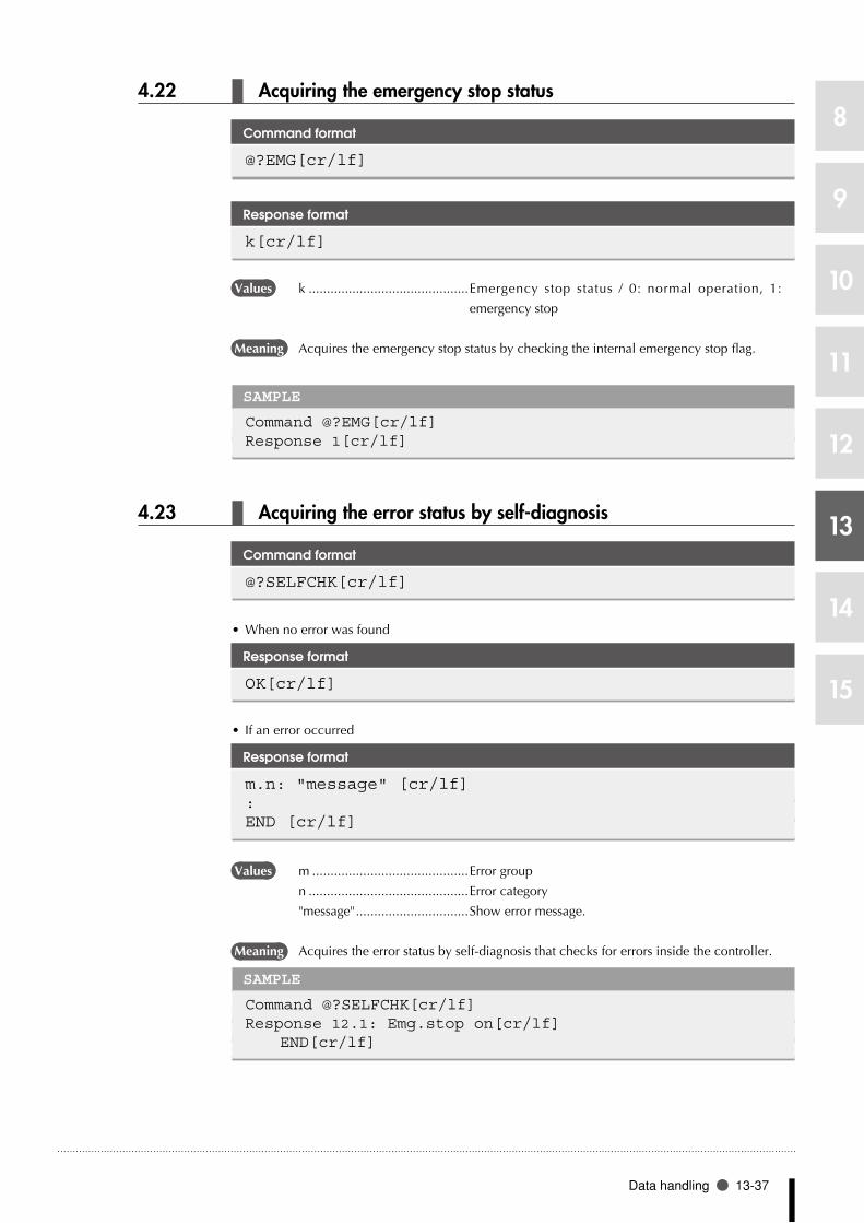
Data handling 13-37
8
9
10
11
12
13
14
15
4.22 Acquiring the emergency stop status
Command format
@?EMG[cr/lf]
Response format
k[cr/lf]
Values k ............................................ Emergency stop status / 0: normal operation, 1:
emergency stop
Meaning Acquires the emergency stop status by checking the internal emergency stop flag.
SAMPLE
Command @?EMG[cr/lf]Response 1[cr/lf]
4.23 Acquiring the error status by self-diagnosis
Command format
@?SELFCHK[cr/lf]
When no error was found •
Response format
OK[cr/lf]
If an error occurred •
Response format
m.n: "message" [cr/lf]:END [cr/lf]
Values m ...........................................Error group
n ............................................Error category
"message" ...............................Show error message.
Meaning Acquires the error status by self-diagnosis that checks for errors inside the controller.
SAMPLE
Command @?SELFCHK[cr/lf]Response 12.1: Emg.stop on[cr/lf] END[cr/lf]

13-38 Chapter 13 Online commands
8
9
10
11
12
13
14
15
4.24 Acquiring the option slot status
Command format
@?OPSLOT[cr/lf]
Response format
OP.1 : <option board name> [cr/lf]OP.2 : <option board name> [cr/lf]OP.3 : <option board name> [cr/lf]OP.4 : <option board name> [cr/lf]
Values <option board name> ...........Name of option board installed in the controller.
DIO_Nm ................................DIO board with NPN specifications (m: board ID)
DIO_Pm ................................. DIO board with PNP specifications (m: board ID)
CCLnk .................................... CC-Link compatible board
D_Net .................................... DeviceNet compatible board
Profi ....................................... Profibus compatible board
E_Net ..................................... Ethernet compatible board
no board ................................ No option board is installed.
illegal board ...........................Incompatible board is installed.
Meaning Acquires the option slot status by checking the option boards.
SAMPLE
Command: @?OPSLOT[cr/lf]Response: OP.1: DIO_N2[cr/lf] OP.2: DIO_N1[cr/lf] OP.3: no board[cr/lf] OP.4: CCLnk [cr/lf]

Data handling 13-39
8
9
10
11
12
13
14
15
4.25 Acquiring various values
1. Acquiring the value of a numerical expression
Command format
@? "numerical expression" [cr/lf]
Response format
"numerical value" [cr/lf]
Meaning Acquires the value of the specified numerical expression.
The numerical expression's value format is "decimal" or "real number".
SAMPLE 1
Command: @?SQR(100*5)[cr/lf]Response: 2.23606E01[c/lf]
SAMPLE 2
Command: @?LOCX(WHERE)[cr/lf]Response: 102054[cr/lf]
2. Acquiring the value of a character string expression
Command format
@? "character string expression" [cr/lf]
Response format
"character string " [cr/lf]
Meaning Acquires the value (character string) of the specified character string expression.
SAMPLE
If A$="ABC" and B$="DEF"Command: @?A$+B$+"123"[cr/lf]Response: ABCDEF123[cr/lf]
n NOTE
Numer ical express ion •values can be acquired on the following software versions.
RCX14x Ver. 8.64 onwards
RCX22x Ver. 9.11 onwards
n NOTE
Numer ical express ion •values can be acquired on the following software versions.
RCX14x Ver. 8.64 onwards
RCX22x Ver. 9.11 onwards

13-40 Chapter 13 Online commands
8
9
10
11
12
13
14
15
3. Acquiring the value of a point expression
Command format
@? "point data expression" [cr/lf]
Response format
"point data" [cr/lf]
Meaning Acquires the value (point data) of the specified point expression.
SAMPLE
Command: @?P1+WHRXY[cr/lf]Response: 10.41 -1.60 52.15 3.00 0.00 0.00 0[cr/lf]
4. Acquiring the value of a shift expression
Command format
@? "shift expression" [cr/lf]
Response format
"shift data" [cr/lf]
Meaning Acquires the value (shift data) of the specified shift expression.
SAMPLE
Command: @?s1[cr/lf]Response: 25.00 12.60 10.00 0.00[cr/lf]
n NOTE
Numer ical express ion •values can be acquired on the following software versions.
RCX14x Ver. 8.64 onwards
RCX22x Ver. 9.11 onwards
n NOTE
Numer ical express ion •values can be acquired on the following software versions.
RCX14x Ver. 8.64 onwards
RCX22x Ver. 9.11 onwards

Data handling 13-41
8
9
10
11
12
13
14
15
4.26 Data readout processing
Command format
@READ <readout file> [cr/lf]
Response format
Response output depends on the designated readout file.
Values <readout file> ....................... Designate a readout file name.
Meaning Reads out the data from the designated file.
Online commands that are input through the RS-232C port have the same meaning as
the following command.
• SEND<readoutfile>TOCMU
Commands via Ethernet have the same meaning as the following command.
• SEND<readoutfile>TOETH
Type Readout file nameDefinition format
All Separate fileUser memory All files ALL --------
Program PGM <bbbbbbbb>Point data PNT Pn
Point comment PCM PCnParameter PRM /cccccc/
Shift definition SFT SnHand definition HND HnPallet definition PLT PLn
Variable, constant Variable VAR ab...byArray variable ARY ab...by(x)
Constant "cc...c"Status Program directory DIR <<bbbbbbbb>>
Parameter directory DPM --------Machine reference MRF --------Error history (log) LOG --------
Memory size MEM --------Device DI port DI() DIn()
DO port DO() DOn()MO port MO() MOn()TO port TO() TOn()LO port LO() LOn()SI port SI() SIn()SO port SO() SOn()SIW port SIW() SIWn()SOW port SOW() SOWn()
Others File end code EOF --------
a: Alphabetic character n: Number
b: Alphanumeric character or underscore ( _ ) x: Expression (Array argument)
c: Alphanumeric character or symbol y: variable type
SAMPLE
Command: @READ PGM[cr/lf] @READ P100[cr/lf]
n NOTE
For more in for mat ion •about files, refer to the earlier Chapter 11 "Data file description".
n NOTE
T h e p o i n t c o m m e n t •separate format (PCn) is available on the following software versions.
RCX14x Ver. 8.64 onwards
RCX22x Ver. 9.11 onwards

13-42 Chapter 13 Online commands
8
9
10
11
12
13
14
15
4.27 Data write processing
Command format
@WRITE <write file> [cr/lf]
Response format
Input request display ***Input the data! [cr/lf]After input is completed OK [cr/lf]
Values <write file> ........................... Designate a write file name.
Meaning Writes the data in the designated file.
Online commands that are input through the RS-232C port have the same meaning as
the following command.
•SENDCMUTO<writefile>
Commands via Ethernet have the same meaning as the following command.
•SENDETHTO<writefile>
•At the DO, MO, TO, LO, SO, SOW ports, an entire port (DO(), MO(), etc.) cannot be
designated as a WRITE file.
•Someseparatefiles(DOn(),MOn(),etc.)cannotbedesignatedasaWRITEfile.Fordetails,see
Chapter 11 "Data File Details".
Type Write file nameDefinition format
All Separate file
User memory All files ALL --------
Program PGM <bbbbbbbb>
Point data PNT Pn
Point comment PCM PCn
Parameter PRM /cccccc/
Shift definition SFT Sn
Hand definition HND Hn
Pallet definition PLT PLn
Variable, constant Variable VAR ab...by
Array variable ARY ab...by(x)
Device DO port -------- DOn()
MO port -------- MOn()
TO port -------- TOn()
LO port -------- LOn()
SO port -------- SOn()
SOW port -------- SOWn()
a: Alphabetic character n: Number
b: Alphanumeric character or underscore ( _ ) x: Expression (Array argument)
c: Alphanumeric character or symbol y: variable type
SAMPLE 1
Command: @WRITE PRM[cr/lf] @WRITE P100[cr/lf]
n NOTE
For more in for mat ion •about files, refer to the earlier Chapter 11 "Data file description".
MEMO
n NOTE
T h e p o i n t c o m m e n t •separate format (PCn) is available on the following software versions
RCX14x Ver. 8.64 onwards
RCX22x Ver. 9.11 onwards

Data handling 13-43
8
9
10
11
12
13
14
15
4.28 Current torque value acquisition
Command format
@?CHKTRQ k[cr/lf]@?CHKTRQ2 k[cr/lf]
Values k ... Axis setting (k = 1 to 6).
Response format
n[cr/lf]
Values n ............................................Current torque value (n = -100 to 100) of the specified axis.
* The plus/minus sign indicates the direction.
Meaning •Acquiresthecurrenttorquevalueofthespecifiedaxis.
CHKTRQ: Acquires the current torque value of a main group axis.
CHKTRQ2: Acquires the current torque value of a sub group axis.
SAMPLE
Command: Response:
n NOTE
The "@?CHKTRQ" and •"@?CHKTRQ2" commands a r e a v a i l a b l e f r o m the following software versions:
RCX240 Ver. 10.65 onwards,
RCX22x Ver. 9.36 onwards
If the specified axis has •been set to "no axis" in the system generation, or if that axis uses the YC-Link or a power gripper, a "5 .37: Speci f icat ion mismatch" error message displays and command execution is stopped.

13-44 Chapter 13 Online commands
8
9
10
11
12
13
14
15
5 Executing the robot language independently
5.1 Switching the program
Command format
@SWI <program name>[cr/lf]
Response format
OK[cr/lf] or LINEx,m,n: "message"
Values OK .........................................Program was switched correctly.
LINEx,m,n : "message" ............Error occurred during compiling.
x ............................................Line number on which error occurred
m ...........................................Error group
n ............................................Error category
"message" ...............................Error message
Meaning Switches the program.
•InAUTOmode,theprogramthatisswitchedtowillbecompiled.
•Inothermodes,theprogramisonlyswitched.
However, when "SEQUENCE" program is designated, a sequence object is created.
SAMPLE 1
In AUTO mode:Command @SWI <TEST1>[cr/lf]Response Line2,5.39:Illegal identifier[cr/lf]
SAMPLE 2
In other modes:Command @SWI <TEST1>[cr/lf]Response OK[cr/lf]

Executing the robot language independently 13-45
8
9
10
11
12
13
14
15
5.2 Other robot language command processing
Command format
@"robot language"[cr/lf]
Response format
OK[cr/lf] or ***Aborted
Values OK .........................................Command ended correctly.
***Aborted .............................An error occurred.
Meaning Robot language commands can be executed.
•Independentlyexecutablecommandscanonlybeexecuted.
•Commandformatdependsoneachcommandtobeexecuted.
SAMPLE 1
Command @SET DO(20) [cr/lf]Response OK[cr/lf]
SAMPLE 2
Command @MOVE P,P100,S=20[cr/lf]Response OK[cr/lf]

13-46 Chapter 13 Online commands
8
9
10
11
12
13
14
15
6 Control codes
6.1 Interrupting the command execution
Command format
^C (=03H)
Response format
***Aborted
Meaning Interrupts execution of the current command.
SAMPLE
Command: @MOVE P,P100,S=20[cr/lf] ^CResponse: ***Aborted[cr/lf]

Chapter 14
IO commands
1 1 Overview .................................................14-1
2 2 IO command format ..............................14-1
3 3 Sending and receiving IO commands ...14-3
4 4 IO command list .....................................14-5
5 5 IO command description ......................14-6


Overview 14-1
8
9
10
11
12
13
14
15
1 Overview
Using bit information (DI/DO port) for general-purpose input/output allows issuing commands
directly from the PLC. It is now possible to execute commands such as the MOVE command that
were impossible to execute up until now without using the robot program or RS-232C port.
•In order to use the IO command, the "STD.DIO IO command (DI05)" (located in the SYSTEM
mode's "Other parameters") must be enabled in advance.
•RCX14x ............................ "IO cmd (DI05) on STD.DIO" of other parameters
•RCX22x ............................ "IO cmd (DI05)" of option board parameters
For more details, refer to the Controller user's manual.
•General-purposeoutputsDO26andDO27(dedicatedoutputsDO16andDO17forRCX22x)
are used when executing an IO command. Pay attention to this point when you are using them
for other purposes.
2 IO command format
When using the IO command, the following functions are assigned to each IO.
Output: Controller → PLC
Output port Contents
RCX 14x/40DO26 Execution check outputDO27 Execution in-progress output
RCX 22xDO16 Execution check outputDO17 Execution in-progress output
Input: PLC → Controller
Input port ContentsDI05 IO command execution trigger inputDI2 ( ) Command codeDI3 ( )
Command dataDI4 ( )
IO commands can be executed by using part of the general-purpose input and output. When no ■
connection is made to the option DIO, then DI4() is always recognized as being OFF.
IO commands cannot be executed while program execution is in progress (DO13 is ON). ■
IO commands cannot be executed simultaneously with online commands. ■
IO commands ■ assign command codes to be executed to DI2(), and command data to DI3() and
DI4(). These are executed when the DI05 is changed from OFF to ON. The controller processes
the IO commands when they are received and sends execution check results and execution in-
progress information to the PLC via DO26 and DO27 (DO16 and DO17 for RCX22x).
Command data added to the IO commands will differ according to the IO command. ■
For details, refer to Chapter 14 "5 IO command description".
Data is set in binary code. If the data size is greater than 8 bits, set the upper bit data into the ■
higher address. (little endian)
•Forexample, toset0x0F9F[hexadecimal] (=3999) in theDI3 ()andDI4 ()ports, set0x0F
[hexadecimal] in DI4 () and set 0x9F [hexadecimal] in DI3 ().
The IO command execution trigger input is not accepted when the execution in-progress output ■
is ON.
MEMO
n NOTE
I O c o m m a n d s a r e •available from software version 8.18 onwards.

14-2 Chapter 14 IO commands
8
9
10
11
12
13
14
15
The execution in-progress output is ON in the following cases. ■
•WhenanIOcommandisrunningafterreceivinganIOcommandexecutiontriggerinput.
•WhenanIOcommandisterminatedafterreceivinganIOcommandexecutiontriggerinputyet
a maximum of 100ms state is maintained when IO command trigger input is ON.
The IO command trigger input pulse must always be maintained for 100ms or more during ■
input. Commands cannot be accepted unless this statement is maintained.
Sometimes 20ms or more is needed for the execution in-progress output to turn ON after startup ■
(rising edge) of the IO command trigger input pulse. The IO command trigger input might not be
accepted during this period.
After inputting the IO command trigger input pulse and the in-progress output turns OFF, at least ■
a 100ms time period must always elapse before executing the next command. If this elapsed time
period is too small, the IO command execution trigger input might not be accepted.
The execution check output turns OFF when an IO command is received. ■
The execution check output turns ON when an IO command ends normally, but it remains OFF if ■
the IO command ends abnormally.

Sending and receiving IO commands 14-3
8
9
10
11
12
13
14
15
3 Sending and receiving IO commands
Sending and receiving is performed in the IO register as shown below.
Sending and receiving IO commands
DI05
DI2 ( )
DI3 ( )to DI4 ( )
Command execution trigger
Command code
Command data
Execution in-progress output
Execution check output
Input port
Output port
Execution end
100ms or more
30ms or more
* For the RCX22x, the output ports are as follows: D027 � DO17, DO26 � DO16.
DO27(DO17)
DO26(DO16)
(1)
(1)
(2)
(3)
(4)
(4)
(4)
(5)
(5)
33E01-R7-00
(1) Set command code and command data (Time interval between (1) and (2): 30ms or more)
(2) Set IO command execution trigger input (Pulse width: 100ms or more)
(3) Transition to execute
(4) Clear the IO command execution trigger input and command code and command data
(5) Set termination of IO command and execution check output
•Output port for the execution check output is as follows: RCX14x : DO26
RCX22x : DO16
•Output port for the execution in-progress output is as follows: RCX14x : DO27
RCX22x : DO17
MEMO

14-4 Chapter 14 IO commands
8
9
10
11
12
13
14
15
Example: Follow these steps when sending and receiving IO commands to execute the PTP movement command to point 19.
(1) Set the following values in the register to execute the PTP movement command by designating
a point.
•DI2():Commandcode(0x01)
•DI3():Lowerpointsetting(0x13=point19)
•DI4():Upperpointsetting(0x00=point19)
(2) Set DI05 from ON to OFF.
(3) The controller receives the IO command and executes it if the command and command data
are acceptable. The execution in-progress output turns ON and the execution check output
turns OFF at this time. The robot moves to the position specified by point 19.
(4) Clear DI2( ) through DI4( ) after checking that execution in-progress output is ON.
(5) When the command ends, the output being executed turns OFF, and if execution ended
normally, the execution judgment output turns ON. If execution ended in error, the execution
judgment output remains OFF.
•If DI05 was not set to OFF in (4), the execution in-progress output remains ON for a maximum
of 100ms from the timing in (5).
Sending and receiving IO commands (2)
Command execution trigger
Command code
Command data
Execution in-progress output
Execution check output
Input port
Output port
Execution end
100ms
* For the RCX22x, the output ports are as follows: D027 → DO17, DO26 → DO16.
DI05
DI2 ( )
DI3 ( )to DI4 ( )
DO27(DO17)
DO26(DO16)
(1)
(1)
(2)
(3)
(4)
(4)
(4)
(5)
(5)
33E02-R7-00
MEMO
n NOTE
When a SCARA robot is •used and a hand system flag is set for the point data you specify, that hand system has priority over the cur rent ar m type.

IO command list 14-5
8
9
10
11
12
13
14
15
4 IO command list
IO commands are expressed with hexadecimal codes.
No. Command contentsCommand code (DI2( ))
Main robot Sub robot
1 MOVE command PTP designation 0x01 0x81
Linear interpolation 0x03 0x83
2 MOVEI command PTP designation 0x09 0x89
3 Pallet movement command PTP designation at pallet 0 0x18 0x98
4 Jog movement command 0x20 0xA0
5 Inching movement command 0x24 0xA4
6 Point teaching command 0x28 0xA8
7 Absolute reset movement command 0x30 0xB0
8 Absolute reset command 0x31 0xB1
9 Return-to-origin command 0x32 0xB2
10 Servo command On 0x34 0xB4
Off 0x35 0xB5
Free 0x36 0xB6
Power-on 0x37
11 Manual movement speed change command 0x38 0xB8
12 Auto movement speed change command 0x39 0xB9
13 Program speed change command 0x3A 0xBA
14 Shift designation change command 0x3B 0xBB
15 Hand designation change command 0x3C 0xBC
16 Arm designation change command 0x3D 0xBD
17 Point display unit designation command 0x3E
Remarks
*3 The pallet movement command is only valid for pallet 0.
*4 The movement methods for the JOG, INCHING, and POINT TEACHING commands differ
according to the point units that were specified.
*6 The point teaching command uses different point units according to the point units that were
specified.
*8 If no axis is specified, the absolute reset command is executed on all axes (main robot + sub
robot) in either case of command code 0x31 or 0xB1.
*9 The return-to-origin command applies to both main and sub robots in systems where 2 robots
have been specified.
*17 The point display unit designation command is for use on the controller.
n NOTE
In the MOVE command, •linear interpolation (0x83) f o r s u b r o b o t i s o n l y available on the following software versions.
RCX14x Ver. 8.64 onwards
RCX22x Ver. 9.11 onwards
On cont ro l le r s whose •software version is earlier than 8.45, the return-to-or ig in command i s executed on a l l axes (main robot + sub robot) and command code 0x32 can only be use.

14-6 Chapter 14 IO commands
8
9
10
11
12
13
14
15
5 IO command description
5.1 MOVE command Moves the robot by the absolute position method
1. PTP designation
This command moves the robot to a target position in PTP motion by specifying the point number.
Command
DI port Contents ValueDI2 () Command code For main robot 0x01
For sub robot 0x81DI3 () Point number 0xppppDI4 ()
Values pppp: Point number ...............Specify in 16 bits.
Specified range ......................0 (=0x0000) to 9999(=0x270F)
•In controllers whose software version is earlier than 8.28, point numbers from 0 to 4000 can be
specified.
•Thepointnumbersettingrangeis0to255whenthereisnoDI4().
•WhenaSCARArobotisusedandahandsystemflagissetforthepointdatayouspecify,that
hand system has priority over the current arm type.
2. Linear interpolation
This command moves the robot to a target position by linear interpolation by specifying the point
number.
Command
DI port Contents ValueDI2 () Command code For main robot 0x03
For sub robot 0x83DI3 () Point number 0xppppDI4 ()
Values pppp: Point number ...............Specify in 16 bits.
Specified range ......................0 (=0x0000) to 9999(=0x270F)
•In controllers whose software version is earlier than 8.28, point numbers from 0 to 4000 can be
specified.
•Thepointnumbersettingrangeis0to255whenthereisnoDI4().
•WhenaSCARArobotisusedandahandsystemflagissetforthepointdatayouspecify,that
hand system has priority over the current arm type.
MEMO
c CAUTION
When performing linear •interpolation with a hand system f lag specif ied, be sure that the same hand system is used at the current position and target pos i t ion. I f the same hand system is not used, an error will occur and robot movement will be disabled.
When performing a linear •interpolation, the current p o s i t i o n ' s X - a r m a n d Y-arm rotation information must be the same as the movement destination's X-arm and Y-arm rotation information. If the two are different, an error will occur and movement will be disabled.
MEMO
n NOTE
In the MOVE command, •linear interpolation (0x83) f o r s u b r o b o t i s o n l y available on the following software versions.
RCX14x Ver. 8.64 onwards
RCX22x Ver. 9.11 onwards
X-arm and Y-arm rotation •i n f o r m a t i o n i s o n l y avai lable in sof tware Ver.10.66 onwards.

IO command description 14-7
8
9
10
11
12
13
14
15
5.2 MOVEI command Moves the robot by the relative position method
1. PTP designation
This command moves the robot a specified distance in PTP motion by specifying the point number.
Command
DI port Contents ValueDI2 () Command code For main robot 0x09
For sub robot 0x89DI3 () Point number 0xppppDI4 ()
Values ppppp ....................................Specify the point number in 16 bits.
Specified range: 0 (=0x0000) to 9999 (=0x270F)
•When MOVEI motion to the original target position is interrupted and then restarted, the target
position for the resumed movement can be selected as the "MOVEI/DRIVEI start position" in the
controller's "other parameters". For details, refer to the controller user's manual.
1) KEEP (default setting) ........ Continues the previous (before interruption) movement. The
original target position remains unchanged.
2) RESET ............................... Relative movement begins anew from the current position. The
new target position is different from the original one (before
interruption). (Backward compatibility)
•Incontrollerswhosesoftwareversionisearlierthan8.28,pointnumbersfrom0to4000canbe
specified.
•Thepointnumbersettingrangeis0to255whenthereisnoDI4().
•WhenaSCARArobotisusedandahandsystemflagissetforthepointdatayouspecify,that
hand system has priority over the current arm type.
5.3 Pallet movement command Moves the robot to a position relative to pallet 0
1. PTP designation
This command moves the robot to a target position in PTP motion by specifying the work position
number.
Command
DI port Contents ValueDI2 () Command code For main robot 0x18
For sub robot 0x98DI3 () Work position number 0xwwwwDI4 ()
Values wwww ...................................Specify the work position number in 16 bits.
Specified range: 1 (=0x0001) to 32767 (=0x7FFF)
•The work position number setting range is 0 to 255 when there is no DI4().
n NOTE
This parameter is only •available in the following software versions:
RCX14x Ver. 8.63 onwards
RCX22x Ver. 9.08 onwards
In versions prior to those •shown above, a "RESET" must be performed at the controller.
MEMO
MEMO

14-8 Chapter 14 IO commands
8
9
10
11
12
13
14
15
5.4 Jog movement command Performs robot JOG movement in the MANUAL mode.
This command is only valid in MANUAL mode.
This command is linked with the controller point display units. The robot axis moves in PTP motion
when display units are in pulses, and moves by linear interpolation on Cartesian coordinates when
units are in millimeters.
Jog speed is determined by the manual movement speed.
To stop the jog movement command, set the dedicated input interlock signal to OFF. After checking
that jog movement has stopped, set the interlock signal back to ON.
Command
DI port Contents ValueDI2 () Command code For main robot 0x20
For sub robot 0xA0DI3 () Axis to move and direction bit 0 Axis 1 tt
bit 1 Axis 2
bit 2 Axis 3
bit 3 Axis 4
bit 4 Axis 5
bit 5 Axis 6
bit 6 (0:Fixed) 0
bit 7 Direction dDI4 () Not used 0x00
Values tt: Axis setting .........................Bits 0 to 3 select 1 axis
d: Movement direction ...........Bit 1 / 0: plus direction; 1: minus direction
5.5 Inching movement command Performs robot INCHING movement in the MANUAL mode.
Inching movement distance is linked to the manual movement speed. The inching command can
only be executed in MANUAL mode.
This command is linked with the controller’s point display unit system. So when display units are in
pulses, the axis moves a certain number of pulses at the manual speed setting. When display units
are in millimeters, the axis moves on Cartesian coordinates by linear interpolation at the manual
speed setting divided by 100.
Command
DI port Contents ValueDI2 () Command code For main robot 0x24
For sub robot 0xA4DI3 () Axis to move and direction bit 0 Axis 1 tt
bit 1 Axis 2
bit 2 Axis 3
bit 3 Axis 4
bit 4 Axis 5
bit 5 Axis 6
bit 6 (0:Fixed) 0
bit 7 Direction dDI4 () Not used 0x00
Values tt: Axis setting .........................Bits 0 to 3 select 1 axis
d: Movement direction ...........Bit 1 / 0: plus direction; 1: minus direction

IO command description 14-9
8
9
10
11
12
13
14
15
5.6 Point teaching command Teaches the robot's current position to a specified point No.
Point data units of this command are linked to the controller's point display unit system.
Command
DI port Contents ValueDI2 () Command code For main robot 0x28
For sub robot 0xA8DI3 () Point number 0xppppDI4 ()
Values pppp: Point number ...............Specify in 16 bits.
Specified range ......................0 (=0x0000) to 9999(=0x270F)
•In controllers whose software version is earlier than 8.28, point numbers from 0 to 4000 can be
specified.
•Thepointnumbersettingrangeis0to255whenthereisnoDI4().
5.7 Absolute reset movement command Moves the nearest position where an absolute reset is possible
When absolute reset of the specified axis uses the mark method, this command moves the axis to
the nearest position where absolute reset can be executed.
Positions capable of absolute reset are located at every 1/4 rotation of the motor.
Command
DI port Contents ValueDI2 () Command code For main robot 0x30
For sub robot 0xB0DI3 () Axis to move and direction bit 0 Axis 1 tt
bit 1 Axis 2
bit 2 Axis 3
bit 3 Axis 4
bit 4 Axis 5
bit 5 Axis 6
bit 6 (0:Fixed) 0
bit 7 Direction dDI4 () Not used 0x00
Values tt: Axis setting .........................Bits 0 to 3 select 1 axis
d: Movement direction ...........Bit 1 / 0: plus direction; 1: minus direction
MEMO

14-10 Chapter 14 IO commands
8
9
10
11
12
13
14
15
5.8 Absolute reset command Executes absolute reset of the specified axis.
If no axis is specified, the absolute reset command is executed on all axes (main robot + sub robot)
in either case of command code 0x31 or 0xB1.
However, this command cannot be executed if return-to-origin is not yet complete on the axis using
the mark method. In this case, perform absolute reset individually on each axis.
Command
DI port Contents ValueDI2 () Command code For main robot 0x31
For sub robot 0xB1DI3 () Axis specification bit 0 Axis 1 tt
bit 1 Axis 2
bit 2 Axis 3
bit 3 Axis 4
bit 4 Axis 5
bit 5 Axis 6
bit 7 - bit 6 (0:Fixed) 0DI4 () Not used 0x00
Values tt: Axis specification ............... Bits 0 to 3 select 1 axis (if not specified, the command
applies to all the main group and sub group axes).
5.9 Return-to-origin command Executes an incremental axis return-to-origin
When this command is executed on an incremental mode axis, that axis returns to its origin. When
executed on a semi-absolute mode axis, an absolute search is performed on that axis.
If no axis is specified (DI3() is 0), this command is executed on all axes (main robot + sub robot) in
either case of 0x32 or 0xB2.
Command
DI port Contents ValueDI2 () Command code For main robot 0x32
For sub robot 0xB2DI3 () Axis specification bit 0 Axis 1 tt
bit 1 Axis 2
bit 2 Axis 3
bit 3 Axis 4
bit 4 Axis 5
bit 5 Axis 6
bit 7 - bit 6 (0:Fixed) 0DI4 () Not used 0x00
Values tt: Axis specification ............... Bits 0 to 3 select 1 axis (if not specified, the command
applies to all the main group and sub group axes).
n NOTE
This parameter is only •available in the following software versions:
RCX14x Ver. 8.63 onwards
RCX22x Ver. 9.08 onwards
In versions prior to those •shown above, a "RESET" must be performed at the controller.
An axis can be specified •with the return-to-origin command from software vers ion 8.45 onwards. O n e a r l i e r v e r s i o n controllers, return-to-origin is performed on all axes and command code 0x32 can only be used.

IO command description 14-11
8
9
10
11
12
13
14
15
5.10 Servo command Operates the robot servo
These commands operate the robot servos, and switch the servos between their ON, OFF, and FREE
settings in an axis-specific manner.
Operation Contents
Servo ON Execute this command to turn on the servo of a specified axis. The motor power must be turned on when specifying the axis.All controller servos are turned on if no axis is specified.
Servo OFF Execute this command to turn off the servo of a specified axis.All controller servos are turned off if no axis is specified.
Servo Free Execute this command to turn off the mechanical brake and dynamic brake after turning off the servo of a specified axis. Servo OFF and Free are repeated when this command is consecutively executed.All controller servos will be free if no axis is specified.
Power ON Execute this command to turn on the motor power.No axis can be specified.
Command
DI port Contents ValueDI2 () Command code Servo ON For main robot 0x34
For sub robot 0xB4Servo OFF For main robot 0x35
For sub robot 0xB5Servo Free For main robot 0x36
For sub robot 0xB6Power ON All controller servos 0x37
DI3 () Axis specification bit 0 Axis 1 ttbit 1 Axis 2bit 2 Axis 3bit 3 Axis 4bit 4 Axis 5bit 5 Axis 6bit 7 - bit 6 (0:Fixed) 0
DI4 () Not used 0x00
Values tt: Axis specification ............... Bits 0 to 3 select 1 axis (if not specified, the command
applies to all controller processing).
No axis can be specified when executing Power ON.
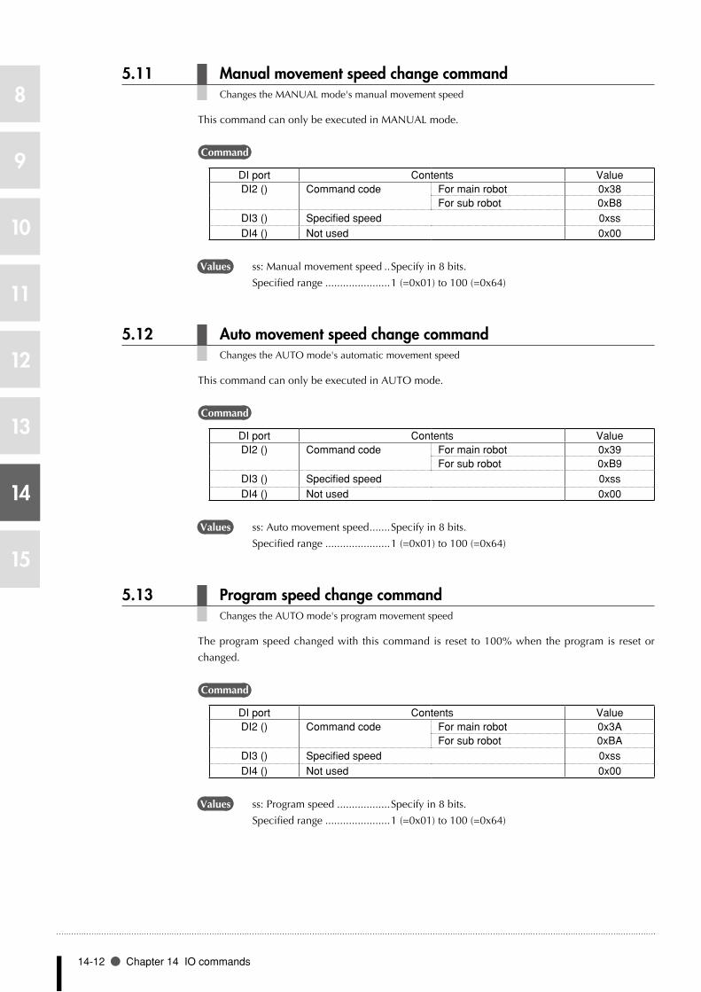
14-12 Chapter 14 IO commands
8
9
10
11
12
13
14
15
5.11 Manual movement speed change command Changes the MANUAL mode's manual movement speed
This command can only be executed in MANUAL mode.
Command
DI port Contents ValueDI2 () Command code For main robot 0x38
For sub robot 0xB8DI3 () Specified speed 0xssDI4 () Not used 0x00
Values ss: Manual movement speed ..Specify in 8 bits.
Specified range ......................1 (=0x01) to 100 (=0x64)
5.12 Auto movement speed change command Changes the AUTO mode's automatic movement speed
This command can only be executed in AUTO mode.
Command
DI port Contents ValueDI2 () Command code For main robot 0x39
For sub robot 0xB9DI3 () Specified speed 0xssDI4 () Not used 0x00
Values ss: Auto movement speed .......Specify in 8 bits.
Specified range ......................1 (=0x01) to 100 (=0x64)
5.13 Program speed change command Changes the AUTO mode's program movement speed
The program speed changed with this command is reset to 100% when the program is reset or
changed.
Command
DI port Contents ValueDI2 () Command code For main robot 0x3A
For sub robot 0xBADI3 () Specified speed 0xssDI4 () Not used 0x00
Values ss: Program speed ..................Specify in 8 bits.
Specified range ......................1 (=0x01) to 100 (=0x64)

IO command description 14-13
8
9
10
11
12
13
14
15
5.14 Shift designation change command Changes a selected shift to the specified shift No.
Command
DI port Contents ValueDI2 () Command code For main robot 0x3B
For sub robot 0xBBDI3 () Specified shift number 0xssDI4 () Not used 0x00
Values ss: Shift number ......................Specify in 8 bits.
Specified range ......................0 (=0x00) to 9 (=0x09)
5.15 Hand designation change command Changes a selected hand to the specified hand No.
Command
DI port Contents ValueDI2 () Command code For main robot 0x3C
For sub robot 0xBCDI3 () Specified hand number 0xssDI4 () Not used 0x00
Values ss: Hand number ....................Specify in 8 bits.
Specified range ......................For main robot: 0 (=0x00) to 3 (=0x03)
For sub robot: 4 (=0x04) to 7 (=0x07)
5.16 Arm designation change command Changes the arm setting status
Command
DI port Contents ValueDI2 () Command code For main robot 0x3D
For sub robot 0xBDDI3 () Status of specified arm 0xssDI4 () Not used 0x00
Values ss: Arm designation status ...... Specify in 8 bits / 0x00: Right-handed system, 0x01:
Left-handed system
5.17 Point display unit designation command Changes the point display unit system
This command is for the controller.
Command
DI port Contents ValueDI2 () Command code For controller 0x3EDI3 () Display units for specified point 0xssDI4 () Not used 0x00
Values ss: Point display unit ............. Specify in 8 bits / 0x00: Pulse units, 0x01: Millimeter
units


Chapter 15
Appendix
1 1 Reserved word list ..................................15-1
2 2 Robot Language Lists: Command list in alphabetic order ...15-3
3 3 Robot Language Lists: Function Specific ...15-8
4 4 Functions: in alphabetic order ............ 15-15
5 5 Functions: operation-specific ............. 15-18
6 6 Execution Level..................................... 15-20


Reserved word list 15-1
8
9
10
11
12
13
14
15
1 Reserved word list
The words shown below are reserved for robot language and cannot be used as identifiers (variables, etc.).
A
ABSADJ
ABSADJ2
ABSRESET
ABSRESET2
ABSRPOS
ABSRPOS2
ABSRST
ABOVE
ABS
ABSINIT
ABSINIT2
ACC
ACCEL
ACCEL2
ACCESS
ALL
AND
ARCH
ARCH2
ARM
ARM2
ARMTYPE
ARMTYPE2
ARY
ASPEED
ASPEED2
ATN
ATN2
ATTR
AUTO
AXWGHT
AXWGHT2
B
BELOW
BIN
BIT
BREAK
BYTE
C
CALL
CASE
CHANGE
CHANGE2
CHGPRI
CHGTSK
CHKTRQ
CHKTRQ2
CHR
CMU
CMU1
CONFIG
CONT
COO
COPY
COS
CURTRQ
CURTRQ2
CUT
D
DATE
DEC
DECEL
DECEL2
DECLARE
DEF
DEFIO
DEFPOS
DEGRAD
DELAY
DI
DIM
DIR
DIST
DO
DPM
DRIVE
DRIVE2
DRIVEI
DRIVEI2
DS
DSPEED
E
ELSE
ELSEIF
EMGRST
EMG
END
ENDIF
EOF
ERA
ERL
ERR
ERROR
ETH
EXELVL
EXIT
EXITTASK
F
FDD
FLIP
FN
FOR
FREE
FUNCTION
G
GASP
GEN
GO
GOHOME
GOSUB
GOTO
H
HALT
HAND
HAND2
HND
HEX
HOME
HOLD
I
IF
IN
INCH
INCH2
INIT
INPUT
INT
INTEGER
IRET
J
JTOXY
JTOXY2
JOG
JOG2
L
LANGUAGE
LEFT
LEFTY
LEFTY2
LEN
LET
LOCA
LOCB
LOCF
LOCR
LOCX
LOCY
LOCZ
LOG
LOOP
LSHIFT
M
MANUAL
MCHREF
MCHREF2
MEM
MID
MIRROR
MOD
MOVE
MOVE2
MOVEI
MOVEI2
MRF
MSG
MSGCLR
MSPEED
MSPEED2
N
NAME
NEXT
NONFLIP
NOT
O
OFF
OFFLINE
ON
ONLINE
OR
ORD
ORGORD
ORGORD2
ORGRTN
ORGRTN2
ORIGIN
OUT
OUTPOS

15-2 Chapter 15 Appendix
8
9
10
11
12
13
14
15
Because the following names are used as system variable names, they cannot be used at the beginning of other variable names (n: numeric value).
DIn Hn Pn SOn
DOn LOn SIn TOn
FN MOn Sn
Variable name usage examples
Although keywords which are reserved as robot language words cannot be used as they are, ■ they can be used as
variable names if alphanumeric characters are added to them.
Example: "ABS" cannot be used, but "ABS1" or "ABSX" can be used.
Keywords reserved as system variables cannot be used at the beginning of other variable names, even if ■
alphanumeric characters are added to them.
Example: "FN" cannot be used. "FNA" and "FN123" also cannot be used.
OUTPOS2
P
P
PASS
PADDR
PATH
PC
PCM
PDEFPLN
PLT
PMOVE
PMOVE2
PROGRAM
PGM
PNT
POS
PPNT
PRM
PTP
PWR
R
RADDEG
READ
REF
REN
RELESE
REM
REMOTE
RESET
RESTART
RESUME
RETURN
RIGHT
RIGHTY
RIGHTY2
RO
ROTATE
RSHIFT
RUN
RW
S
S
SELECT
SEND
SEQUENCE
SERVO
SERVO2
SET
SFT
SGI
SGR
SHARED
SHIFT
SHIFT2
SI
SID
SIN
SIW
SKIP
SO
SOD
SOW
SPEED
SPEED2
SQR
START
STEP
STOP
STOPON
STR
SUB
SUSPEND
SWI
SYS
SYSTEM
T
TAN
TASK
TASKS
TCOUNTER
TEACH
TEACH2
THEN
TIME
TIMER
TO
TOLE
TOLE2
TORQUE
TORQUE2
TRQSTS
TRQSTS2
TRQTIME
TRQTIME2
TSKMON
U
UNIT
UNTIL
V
VAL
VAR
VER
VEL
W
WAIT
WEIGHT
WEIGHT2
WEND
WHERE
WHERE2
WHILE
WHRXY
WHRXY2
WHRXYEX
WHRXYEX2
WORD
WRITE
X
XOR
XY
XYTOJ
XYTOJ2
Y
YZ
Z
ZX
SYMBOL
_SYSFLG

Robot Language Lists: Command list in alphabetic order 15-3
8
9
10
11
12
13
14
15
2 Robot Language Lists: Command list in alphabetic order
No1 Command Function Condition Direct Type
A1 ABS Acquires the absolute value of a specified value. - - Functions
2 ABSINIT Resets the current position of a specified main group axis.
4 Command Statements
2 ABSINIT2 Resets the current position of a specified sub group axis.
4 Command Statements
3 ABSRPOS Acquires the machine reference of the specified main group axis. (Valid only for axes where the return-to-origin method is set as "mark method".)
- - Functions
3 ABSRPOS2 Acquires the machine reference of the specified sub group axis. (Valid only for axes where the return-to-origin method is set as "mark method".)
- - Functions
4 ABSRST Executes a return-to-origin at the robot absolute motor axes.
4 Command Statements
5 ACCEL Specifies/acquires the acceleration coefficient parameter of the main group.
4/- Command Statements/Functions
5 ACCEL2 Specifies/acquires the acceleration coefficient parameter of the sub group.
4/- Command Statements/Functions
6 ARCH Specifies/acquires the arch position parameter of the main group.
4/- Command Statements/Functions
6 ARCH2 Specifies/acquires the arch position parameter of the sub group.
4/- Command Statements/Functions
7 ARMCND Acquires the current arm status of the main robot. - - Functions
7 ARMCND2 Acquires the current arm status of the sub robot. - - Functions
8 ARMTYPE Acquires the current "hand system" setting of the main robot. - - Functions
8 ARMTYPE2 Acquires the current "hand system" setting of the sub robot. - - Functions
10 ASPEED Changes the AUTO movement speed of the main group. 4 Command Statements
10 ASPEED2 Changes the AUTO movement speed of the sub group. 4 Command Statements
9 ATN Acquires the arctangent of the specified value. - - Functions
11 AXWGHT Specifies/acquires the axis tip weight parameter of the main group.
4/- Command Statements/Functions
11 AXWGHT2 Specifies/acquires the axis tip weight parameter of the sub group.
4/- Command Statements/Functions
C12 CALL Executes (calls) another program. 6 Command Statements
13 CHANGE Switches the main robot hand. 4 Command Statements
13 CHANGE2 Switches the sub robot hand. 4 Command Statements
14 CHGPRI Changes the priority ranking of a specified task. 6 Command Statements
15 CHR$ Acquires a character with the specified character code. - - Functions
16 COS Acquires the cosine value of a specified value. - - Functions
17 CURTRQ Acquires the current torque value of the specified main group axis.
- Functions
17 CURTRQ2 Acquires the current torque value of the specified sub group axis.
- Functions
18 CUT Terminates a task currently being executed or temporarily stopped.
6 Command Statements
D19 DATE$ Acquires the date as a "yy/mm/dd" format character string. - - Functions

15-4 Chapter 15 Appendix
8
9
10
11
12
13
14
15
No1 Command Function Condition Direct Type
20 DECEL Specifies/acquires the deceleration rate parameter of the main group.
4/- Command Statements/Functions
20 DECEL2 Specifies/acquires the deceleration rate parameter of the sub group.
4/- Command Statements/Functions
23 DEGRAD Converts a specified value to radians (↔RADDEG). - - Functions
24 DELAY Waits for the specified period (units: ms). 6 Command Statements
27 DIM Declares the array variable name and the number of elements.
6 Command Statements
26 DIST Acquires the distance between 2 specified points. - - Functions
28 DO Outputs a specified value to the DO port. 1 Command Statements
29 DRIVE Moves a specified main group axis to an absolute position. 4 Command Statements
29 DRIVE (With T-option) Executes an absolute movement command for a specified axis.
4 Command Statements
29 DRIVE2 Moves a specified sub group axis to an absolute position. 4 Command Statements
30 DRIVEI Moves a specified main group axis to a relative position. 4 Command Statements
30 DRIVEI2 Moves a specified sub group axis to a relative position. 4 Command Statements
E33 ERL Gives the line No. where an error occurred. - - Functions
33 ERR Gives the error code number of an error which has occurred. - - Functions
34 EXIT FOR Terminates the FOR to NEXT statement loop. 6 Command Statements
36 EXIT TASK Terminates its own task which is in progress. 6 Command Statements
F37 FOR to NEXT Controls repetitive operations. Executes the FOR to NEXT
statement repeatedly until a specified value is reached.6 Command Statements
G38 GOSUB to
RETURNJumps to a subroutine with the label specified by a GOSUB statement, and executes that subroutine.
6 Command Statements
39 GOTO Unconditionally jumps to the line specified by a label. 6 Command Statements
H40 HALT Stops the program and performs a reset. 6 Command Statements
41 HAND Defines the main robot hand. 4 Command Statements
41 HAND2 Defines the sub robot hand. 4 Command Statements
42 HOLD Temporarily stops the program. 6 Command Statements
I43 IF Allows control flow to branch according to conditions. 6 Command Statements
44 INPUT Assigns a value to a variable specified from the programming box.
1 Command Statements
45 INT Acquires an integer for a specif ied value by truncating all decimal fractions.
- - Functions
J46 JTOXY Converts joint coordinate data to main group
Cartesian coordinate data. (↔XYTOJ)- - Functions
46 JTOXY2 Converts joint coordinate data to sub group Cartesian coordinate data. (↔XYTOJ2)
- - Functions
L48 LEFT$ Extracts a character string comprising a specified
number of digits from the left end of a specified character string.
- - Functions
49 LEFTY Sets the main robot hand system to "Left". 4 Command Statements

Robot Language Lists: Command list in alphabetic order 15-5
8
9
10
11
12
13
14
15
No1 Command Function Condition Direct Type
49 LEFTY2 Sets the sub robot hand system to "Left". 4 Command Statements
50 LEN Acquires the length (number of bytes) of a specified character string.
- - Functions
51 LET Executes a specified assignment statement. 1 Command Statements
52 LO Outputs a specified value to the LO port to enable/disable axis movement.
1 Command Statements
53 LOCx Specifies/acquires point data or shift data for a specified axis.
- - Command Statements/Functions
54 LSHIFT Shifts a value to the left by the specified number of bits. (↔RSHIFT)
- - Functions
M55 MCHREF Acquires the return-to-origin or absolute-search
machine reference for a specified main group axis.- - Functions
55 MCHREF2 Acquires the return-to-origin or absolute-search machine reference for a specified sub group axis.
- - Functions
56 MID$ Extracts a character string of a desired length from a specified character string.
- - Functions
57 MO Outputs a specified value to the MO port. 1 Command Statements
58 MOVE Performs absolute movement of all main robot axes. 5 Command Statements
58 MOVE2 Performs absolute movement of all sub robot axes. 5 Command Statements
59 MOVEI Performs relative movement of all main robot axes. 4 Command Statements
59 MOVEI2 Performs relative movement of all sub robot axes. 4 Command Statements
O60 OFFLINE Sets a specified communication port to the "offline" mode. 1 Command Statements
62 ON ERROR GOTO
If an error occurs during program execution, this command allows the program to jump to the error processing routine specified by the label without stopping the program, or it stops the program and displays the error message.
6 Command Statements
63 ON to GOSUB Jumps to a subroutine with labels specified by a GOSUB statement in accordance with the conditions, and executes that subroutine.
6 Command Statements
64 ON to GOTO Jumps to label-specified lines in accordance with the conditions.
6 Command Statements
65 ONLINE Sets the specified communication port to the "online" mode. 1 Command Statements
61 ORD Acquires the character code of the first character in a specified character string.
- - Functions
66 ORGORD Specifies/acquires the axis sequence parameter for performing return-to-origin and absolute search operations in the main group.
4/- Command Statements/Functions
66 ORGORD2 Specifies/acquires the axis sequence parameter for performing return-to-origin and absolute search operations in the sub group.
4/- Command Statements/Functions
67 ORIGIN Executes a return-to-origin for incremental specs. axes. 4 Command Statements
68 OUT Turns ON the bits of the specified output ports and the command statement ends.
6 Command Statements
69 OUTPOS Specif ies/acquires the OUT enable posit ion parameter of the main group.
4/- Command Statements/Functions
69 OUTPOS2 Specif ies/acquires the OUT enable posit ion parameter of the sub group.
4/- Command Statements/Functions
P70 PATH Sets the movement path. 6 Command Statements
71 PATH END Ends the movement path setting. 6 Command Statements
72 PATH SET Starts the movement path setting. 6 Command Statements

15-6 Chapter 15 Appendix
8
9
10
11
12
13
14
15
No1 Command Function Condition Direct Type
73 PATH START Starts the PATH motion. 6 Command Statements
74 PDEF Defines the pallet used to execute pallet movement commands.
1 Command Statements
75 PMOVE Executes the main robot pallet movement command. 4 Command Statements
75 PMOVE2 Executes the sub robot pallet movement command. 4 Command Statements
76 Pn Defines points within a program. 1 Command Statements
77 PPNT Creates point data specified by a pallet definition number and pallet position number.
- - Functions
78 PRINT Displays a character string at the programming box screen. 1 Command Statements
R79 RADDEG Converts a specified value to degrees. (↔DEGRAD) - - Functions
80 REM Expresses a comment statement. 6 Command Statements
81 RESET Turns the bit of a specified output port OFF. 1 Command Statements
82 RESTART Restarts another task during a temporary stop. 6 Command Statements
83 RESUME Resumes program execution after error recovery processing.
6 Command Statements
85 RIGHT$ Extracts a character string comprising a specified number of digits from the right end of a specified character string.
- - Functions
86 RIGHTY Sets the main robot hand system to "Right". 4 Command Statements
86 RIGHTY2 Sets the sub robot hand system to "Right". 4 Command Statements
87 RSHIFT Shifts a value to the right by the specified number of bits. (↔LSHIFT)
- - Functions
S88 Sn Defines the shift coordinates within the program. 4 Command Statements
89 SELECT CASE to END SELECT
Allows control flow to branch according to conditions. 6 Command Statements
90 SEND Sends a file. 1 Command Statements
91 SERVO Controls the servo ON/OFF of specified main group axes or all main group axes.
4 Command Statements
91 SERVO2 Controls the servo ON/OFF of specified sub group axes or all sub group axes.
4 Command Statements
92 SET Turns the bit at the specified output port ON. 3 In part Command Statements
94 SHIFT Sets the shift coordinates for the main robot by using the shift data specified by a shift variable.
4 Command Statements
94 SHIFT2 Sets the shift coordinates for the sub robot by using the shift data specified by a shift variable.
4 Command Statements
95 SIN Acquires the sine value for a specified value. - - Functions
96 SO Outputs a specified value to the SO port. 1 Command Statements
97 SPEED Changes the main group's program movement speed. 4 Command Statements
97 SPEED2 Changes the sub group's program movement speed. 4 Command Statements
98 START Specifies the task number and priority ranking of a specified task, and starts that task.
6 Command Statements
99 STR$ Converts a specified value to a character string (↔VAL) - - Functions
100 SQR Acquires the square root of a specified value. - - Functions
102 SUSPEND Temporarily stops another task which is being executed. 6 Command Statements
103 SWI Switches the program being executed, performs compiling, then begins execution from the first line.
2 Command Statements
T104 TAN Acquires the tangent value for a specified value. - - Functions

Robot Language Lists: Command list in alphabetic order 15-7
8
9
10
11
12
13
14
15
No1 Command Function Condition Direct Type
105 TCOUNTER Outputs count-up values at 10ms intervals starting from the point when the TCOUNTER variable is reset.
- - Functions
106 TIME$ Acquires the current time as an "hh:mm:ss" format character string.
- - Functions
107 TIMER Acquires the current time in seconds, counting from 12:00 midnight.
- - Functions
108 TO Outputs a specified value to the TO port. 1 Command Statements
109 TOLE Specif ies/acquires the main group tolerance parameter.
4/- Command Statements/Functions
109 TOLE2 Speci f ies/acquires the sub group tolerance parameter.
4/- Command Statements/Functions
110 TORQUE Specifies/acquires the maximum torque command value which can be set for a specified main group axis.
4/- Command Statements/Functions
110 TORQUE2 Specifies/acquires the maximum torque command value which can be set for a specified sub group axis.
4/- Command Statements/Functions
111 TRQSTS Acquires the command end status for the DRIVE command with torque limit option executed at the main group.
- - Functions
111 TRQSTS2 Acquires the command end status for the DRIVE command with torque limit option executed at the sub group.
- - Functions
112 TRQTIME Specifies/acquires the current limit time-out period at the specified main group axis when using a torque limit option in the DRIVE statement.
1/- Command Statements/Functions
112 TRQTIME2 Specifies/acquires the current limit time-out period at the specified sub group axis when using a torque limit setting option in the DRIVE statement.
1/- Command Statements/Functions
V113 VAL Converts the numeric value of a specified character
string to an actual numeric value. (↔STR$)- - Functions
W114 WAIT Waits until the conditions of the DI/DO conditional
expression are met (with time-out).6 Command Statements
115 WAIT ARM Waits until the main group robot axis operation is completed. 6 Command Statements
115 WAIT ARM2 Waits until the sub group robot axis operation is completed. 6 Command Statements
116 WEIGHT Specif ies/acquires the main robot t ip weight parameter.
4/- Command Statements/Functions
116 WEIGHT2 Specif ies/acquires the sub robot t ip weight parameter.
4/- Command Statements/Functions
118 WHERE Reads out the current position of the main group robot arm in joint coordinates (pulses).
- - Functions
118 WHERE2 Reads out the current position of the sub group robot arm in joint coordinates (pulses).
- - Functions
119 WHILE to WEND Controls repeated operations. 6 Command Statements
120 WHRXY Reads out the current position of the main group arm as Cartesian coordinates (mm, degrees).
- - Functions
120 WHRXY2 Reads out the current position of the sub group arm as Cartesian coordinates (mm, degrees).
- - Functions
X121 XYTOJ Converts the point variable Cartesian coordinate data
to the main group's joint coordinate data (↔JTOXY).- - Functions
121 XYTOJ2 Converts the point variable Cartesian coordinate data to the sub group's joint coordinate data (↔JTOXY2).
- - Functions
122 _SYSFLG Axis status monitoring flag. - - Functions

15-8 Chapter 15 Appendix
8
9
10
11
12
13
14
15
3 Robot Language Lists: Function Specific
Program commands
General commands
No1 Command Function Condition Direct Type
27 DIM Declares the array variable name and the number of elements.
6 Command Statements
51 LET Executes a specified assignment statement. 1 Command Statements
80 REM Expresses a comment statement. 6 Command Statements
Arithmetic commands
No1 Command Function Condition Direct Type
1 ABS Acquires the absolute value of a specified value. - - Functions
2 ABSINIT Resets the current position of a specified main group axis.
4 Command Statements
2 ABSINIT2 Resets the current position of a specified sub group axis.
4 Command Statements
9 ATN Acquires the arctangent of the specified value. - - Functions
16 COS Acquires the cosine value of a specified value. - - Functions
23 DEGRAD Converts a specified value to radians (↔RADDEG). - - Functions
26 DIST Acquires the distance between 2 specified points. - - Functions
45 INT Acquires an integer for a specif ied value by truncating all decimal fractions.
- - Functions
54 LSHIFT Shifts a value to the left by the specified number of bits. (↔RSHIFT)
- - Functions
79 RADDEG Converts a specified value to degrees. (↔DEGRAD) - - Functions
87 RSHIFT Shifts a value to the right by the specified number of bits. (↔LSHIFT)
- - Functions
95 SIN Acquires the sine value for a specified value. - - Functions
100 SQR Acquires the square root of a specified value. - - Functions
104 TAN Acquires the tangent value for a specified value. - - Functions
Date / time
No1 Command Function Condition Direct Type
19 DATE $ Acquires the date as a "yy/mm/dd" format character string.
- - Functions
105 TCOUNTER Outputs count-up values at 10ms intervals starting from the point when the TCOUNTER variable is reset.
- - Functions
106 TIME $ Acquires the current time as an "hh:mm:ss" format character string.
- - Functions
107 TIMER Acquires the current time in seconds, counting from 12:00 midnight.
- - Functions

Robot Language Lists: Function Specific 15-9
8
9
10
11
12
13
14
15
Character string operation
No1 Command Function Condition Direct Type
15 CHR $ Acquires a character with the specified character code. - - Functions
48 LEFT $ Extracts a character string comprising a specified number of digits from the left end of a specified character string.
- - Functions
50 LEN Acquires the length (number of bytes) of a specified character string.
- - Functions
56 MID $ Extracts a character string of a desired length from a specified character string.
- - Functions
61 ORD Acquires the character code of the first character in a specified character string.
- - Functions
85 RIGHT $ Extracts a character string comprising a specified number of digits from the right end of a specified character string.
- - Functions
99 STR $ Converts a specified value to a character string (↔VAL) - - Functions
113 VAL Converts the numeric value of a specified character string to an actual numeric value. (↔STR$)
- - Functions
Point, coordinates, shift coordinates
No1 Command Function Condition Direct Type
13 CHANGE Switches the main robot hand. 4 Command Statements
13 CHANGE2 Switches the sub robot hand. 4 Command Statements
41 HAND Defines the main robot hand. 4 Command Statements
41 HAND2 Defines the sub robot hand. 4 Command Statements
46 JTOXY Converts joint coordinate data to main group Cartesian coordinate data. (↔XYTOJ)
- - Functions
46 JTOXY2 Converts joint coordinate data to sub group Cartesian coordinate data. (↔XYTOJ2)
- - Functions
49 LEFTY Sets the main robot hand system to "Left". 4 Command Statements
49 LEFTY2 Sets the sub robot hand system to "Left". 4 Command Statements
76 Pn Defines points within a program. 1 Command Statements
77 PPNT Creates point data specified by a pallet definition number and pallet position number.
- - Functions
86 RIGHTY Sets the main robot hand system to "Right". 4 Command Statements
86 RIGHTY2 Sets the sub robot hand system to "Right". 4 Command Statements
88 Sn Defines the shift coordinates in the program. 4 Command Statements
94 SHIFT Sets the shift coordinates for the main robot by using the shift data specified by a shift variable.
4 Command Statements
94 SHIFT2 Sets the shift coordinates for the sub robot by using the shift data specified by a shift variable.
4 Command Statements
121 XYTOJ Converts the point variable Cartesian coordinate data to the main group's joint coordinate data (↔JTOXY).
- - Functions
121 XYTOJ2 Converts the point variable Cartesian coordinate data to the sub group's joint coordinate data (↔JTOXY2).
- - Functions
53 LOCx Specifies/acquires point data or shift data for a specified axis.
- - Command Statements/Functions

15-10 Chapter 15 Appendix
8
9
10
11
12
13
14
15
Branching commands
No1 Command Function Condition Direct Type
34 EXIT FOR Terminates the FOR to NEXT statement loop. 6 Command Statements
37 FOR to NEXT Controls repetitive operations. Executes the FOR to NEXT statement repeatedly until a specified value is reached.
6 Command Statements
38 GOSUB to RETURN
Jumps to a subroutine with the label specified by a GOSUB statement, and executes that subroutine.
6 Command Statements
39 GOTO Unconditionally jumps to the line specified by a label. 6 Command Statements
43 IF Allows control flow to branch according to conditions. 6 Command Statements
63 ON to GOSUB Jumps to a subroutine with labels specified by a GOSUB statement in accordance with the conditions, and executes that subroutine.
6 Command Statements
64 ON to GOTO Jumps to label-specified lines in accordance with the conditions.
6 Command Statements
89 SELECT CASE to END SELECT
Allows control flow to branch according to conditions. 6 Command Statements
119 WHILE to WEND Controls repeated operations. 6 Command Statements
Error control
No1 Command Function Condition Direct Type
62 ON ERROR GOTO
If an error occurs during program execution, this command allows the program to jump to the error processing routine specified by the label without stopping the program, or it stops the program and displays the error message.
6 Command Statements
83 RESUME Resumes program execution after error recovery processing.
6 Command Statements
33 ERL Gives the line No. where an error occurred. - - Functions
33 ERR Gives the error code number of an error which has occurred.
- - Functions
Program & task control
Program control
No1 Command Function Condition Direct Type
12 CALL Executes (calls) another program. 6 Command Statements
40 HALT Stops the program and performs a reset. 6 Command Statements
42 HOLD Temporarily stops the program. 6 Command Statements
103 SWI Switches the program being executed, performs compiling, then begins execution from the first line.
2 Command Statements
Task control
No1 Command Function Condition Direct Type
14 CHGPRI Changes the priority ranking of a specified task. 6 Command Statements
18 CUT Terminates a task currently being executed or temporarily stopped.
6 Command Statements
36 EXIT TASK Terminates its own task which is in progress. 6 Command Statements
82 RESTART Restarts another task during a temporary stop. 6 Command Statements
98 START Specifies the task number and priority ranking of a specified task, and starts that task.
6 Command Statements
102 SUSPEND Temporarily stops another task which is being executed. 6 Command Statements

Robot Language Lists: Function Specific 15-11
8
9
10
11
12
13
14
15
Robot control
Robot operations
No1 Command Function Condition Direct Type
4 ABSRST Executes a return-to-origin at the robot absolute motor axes.
4 Command Statements
13 CHANGE Switches the main robot hand. 4 Command Statements
13 CHANGE2 Switches the sub robot hand. 4 Command Statements
29 DRIVE Moves a specified main group axis to an absolute position. 4 Command Statements
29 DRIVE2 Moves a specified sub group axis to an absolute position. 4 Command Statements
30 DRIVEI Moves a specified main group axis to a relative position. 4 Command Statements
30 DRIVEI2 Moves a specified sub group axis to a relative position. 4 Command Statements
41 HAND Defines the main robot hand. 4 Command Statements
41 HAND2 Defines the sub robot hand. 4 Command Statements
49 LEFTY Sets the main robot hand system to "Left". 4 Command Statements
49 LEFTY2 Sets the sub robot hand system to "Left". 4 Command Statements
58 MOVE Performs absolute movement of all main robot axes. 5 Command Statements
58 MOVE2 Performs absolute movement of all sub robot axes. 5 Command Statements
59 MOVEI Performs relative movement of all main robot axes. 4 Command Statements
59 MOVEI2 Performs relative movement of all sub robot axes. 4 Command Statements
67 ORIGIN Executes a return-to-origin for incremental specs. axes. 4 Command Statements
75 PMOVE Executes the main robot pallet movement command. 4 Command Statements
75 PMOVE2 Executes the sub robot pallet movement command. 4 Command Statements
86 RIGHTY Sets the main robot hand system to "Right". 4 Command Statements
86 RIGHTY2 Sets the sub robot hand system to "Right". 4 Command Statements
91 SERVO Controls the servo ON/OFF of specified main group axes or all main group axes.
4 Command Statements
91 SERVO2 Controls the servo ON/OFF of specified sub group axes or all sub group axes.
4 Command Statements
Status acquisition
No1 Command Function Condition Direct Type
3 ABSRPOS Acquires the machine reference of the specified main group axis. (Valid only for axes where the return-to-origin method is set as "mark method".)
- - Functions
3 ABSRPOS2 Acquires the machine reference of the specified sub group axis. (Valid only for axes where the return-to-origin method is set as "mark method".)
- - Functions
7 ARMCND Acquires the current arm status of the main robot. - - Functions
7 ARMCND2 Acquires the current arm status of the sub robot. - - Functions
8 ARMTYPE Acquires the current "hand system" setting of the main robot.
- - Functions
8 ARMTYPE2 Acquires the current "hand system" setting of the sub robot.
- - Functions
55 MCHREF Acquires the return-to-origin or absolute-search machine reference for a specified main group axis.
- - Functions
55 MCHREF2 Acquires the return-to-origin or absolute-search machine reference for a specified sub group axis.
- - Functions
111 TRQSTS Acquires the command end status for the DRIVE command with torque limit option executed at the main group.
- - Functions

15-12 Chapter 15 Appendix
8
9
10
11
12
13
14
15
No1 Command Function Condition Direct Type
111 TRQSTS2 Acquires the command end status for the DRIVE command with torque limit option executed at the sub group.
- - Functions
118 WHERE Reads out the current position of the main group robot arm in joint coordinates (pulses).
- - Functions
118 WHERE2 Reads out the current position of the sub group robot arm in joint coordinates (pulses).
- - Functions
120 WHRXY Reads out the current position of the main group arm as Cartesian coordinates (mm, degrees).
- - Functions
120 WHRXY2 Reads out the current position of the sub group arm as Cartesian coordinates (mm, degrees).
- - Functions
115 WAIT ARM Waits until the main group robot axis operation is completed.
115 WAIT ARM2 Waits until the sub group robot axis operation is completed.
6 × Command Statements
Status change
No1 Command Function Condition Direct Type
5 ACCEL Specifies/acquires the acceleration coefficient parameter of the main group.
4/- Command Statements/Functions
5 ACCEL2 Specifies/acquires the acceleration coefficient parameter of the sub group.
4/- Command Statements/Functions
6 ARCH Specifies/acquires the arch position parameter of the main group.
4/- Command Statements/Functions
6 ARCH2 Specifies/acquires the arch position parameter of the sub group.
4/- Command Statements/Functions
10 ASPEED Changes the AUTO movement speed of the main group.
4 Command Statements
10 ASPEED2 Changes the AUTO movement speed of the sub group.
4 Command Statements
11 AXWGHT Specifies/acquires the axis tip weight parameter of the main group.
4/- Command Statements/Functions
11 AXWGHT2 Specifies/acquires the axis tip weight parameter of the sub group.
4/- Command Statements/Functions
20 DECEL Specifies/acquires the deceleration rate parameter of the main group.
4/- Command Statements/Functions
20 DECEL2 Specifies/acquires the deceleration rate parameter of the sub group.
4/- Command Statements/Functions
66 ORGORD Specifies/acquires the axis sequence parameter for performing return-to-origin and absolute search operations in the main group.
4/- Command Statements/Functions
66 ORGORD2 Specifies/acquires the axis sequence parameter for performing return-to-origin and absolute search operations in the sub group.
4/- Command Statements/Functions
69 OUTPOS Specif ies/acquires the OUT enable posit ion parameter of the main group.
4/- Command Statements/Functions
69 OUTPOS2 Specif ies/acquires the OUT enable posit ion parameter of the sub group.
4/- Command Statements/Functions
74 PDEF Defines the pallet used to execute pallet movement commands.
1 Command Statements
97 SPEED Changes the main group's program movement speed.
4 Command Statements
97 SPEED2 Changes the sub group's program movement speed. 4 Command Statements

Robot Language Lists: Function Specific 15-13
8
9
10
11
12
13
14
15
No1 Command Function Condition Direct Type
109 TOLE Specif ies/acquires the main group tolerance parameter.
4/- Command Statements/Functions
109 TOLE2 Specif ies/acquires the sub group tolerance parameter.
4/- Command Statements/Functions
116 WEIGHT Specif ies/acquires the main robot t ip weight parameter.
4/- Command Statements/Functions
116 WEIGHT2 Specif ies/acquires the sub robot t ip weight parameter.
4/- Command Statements/Functions
Path control
No1 Command Function Condition Direct Type
70 PATH Sets the movement path. 6 Command Statements
71 PATH END Ends the movement path setting. 6 Command Statements
72 PATH SET Starts the movement path setting. 6 Command Statements
73 PATH START Starts the PATH motion. 6 Command Statements
Torque control
No1 Command Function Condition Direct Type
17 CURTRQ Acquires the current torque value of the specified main group axis.
- Functions
17 CURTRQ2 Acquires the current torque value of the specified sub group axis.
- Functions
29 DRIVE (With T-option) Executes an absolute movement command for a specified axis.
4 Command Statements
110 TORQUE Specifies/acquires the maximum torque command value which can be set for a specified main group axis.
4/- Command Statements/Functions
110 TORQUE2 Specifies/acquires the maximum torque command value which can be set for a specified sub group axis.
4/- Command Statements/Functions
112 TRQTIME Specifies/acquires the current limit time-out period at the specified main group axis when using a torque limit option in the DRIVE statement.
1/- Command Statements/Functions
112 TRQTIME2 Specifies/acquires the current limit time-out period at the specified sub group axis when using a torque limit setting option in the DRIVE statement.
1/- Command Statements/Functions
Input/output & communication control
Input/output control
No1 Command Function Condition Direct Type
24 DELAY Waits for the specified period (units: ms). 6 Command Statements
28 DO Outputs a specified value to the DO port. 1 Command Statements
52 LO Outputs a specified value to the LO port to enable/disable axis movement.
1 Command Statements
57 MO Outputs a specified value to the MO port. 1 Command Statements
68 OUT Turns ON the bits of the specified output ports and the command statement ends.
6 Command Statements
81 RESET Turns the bit of a specified output port OFF. 1 Command Statements
92 SET Turns the bit at the specified output port ON. 3 In part Command Statements
96 SO Outputs a specified value to the SO port. 1 Command Statements

15-14 Chapter 15 Appendix
8
9
10
11
12
13
14
15
No1 Command Function Condition Direct Type
108 TO Outputs a specified value to the TO port. 1 Command Statements
114 WAIT Waits until the conditions of the DI/DO conditional expression are met (with time-out).
6 Command Statements
Programming box
No1 Command Function Condition Direct Type
44 INPUT Assigns a value to a variable specified from the programming box.
1 Command Statements
78 PRINT Displays a character string at the programming box screen.
1 Command Statements
Communication control
No1 Command Function Condition Direct Type
65 ONLINE Sets the specified communication port to the "online" mode.
1 Command Statements
60 OFFLINE Sets a specified communication port to the "offline" mode.
1 Command Statements
90 SEND Sends a file. 1 Command Statements
Other
Other
No1 Command Function Condition Direct Type
122 _SYSFLG Axis status monitoring flag. - - Functions

Functions: in alphabetic order 15-15
8
9
10
11
12
13
14
15
4 Functions: in alphabetic order
No1 Function Type Function
A1 ABS Arithmetic function Acquires the absolute value of a specified value.
3 ABSRPOS Arithmetic function Acquires the machine reference of the specified main group axis. (Valid only for axes where the return-to-origin method is set as "mark method".)
3 ABSRPOS2 Arithmetic function Acquires the machine reference of the specified sub group axis. (Valid only for axes where the return-to-origin method is set as "mark method".)
5 ACCEL Arithmetic function Acquires the acceleration coefficient parameter of the main group.
5 ACCEL2 Arithmetic function Acquires the acceleration coefficient parameter of the sub group.
6 ARCH Arithmetic function Acquires the arch position parameter of the main group.
6 ARCH2 Arithmetic function Acquires the arch position parameter of the sub group.
7 ARMCND Arithmetic function Acquires the current arm status of the main robot.
7 ARMCND2 Arithmetic function Acquires the current arm status of the sub robot.
8 ARMTYPE Arithmetic function Acquires the current "hand system" setting of the main robot.
8 ARMTYPE2 Arithmetic function Acquires the current "hand system" setting of the sub robot.
9 ATN Arithmetic function Acquires the arctangent of the specified value.
11 AXWGHT Arithmetic function Acquires the axis tip weight parameter of the main group.
11 AXWGHT2 Arithmetic function Acquires the axis tip weight parameter of the sub group.
C15 CHR$ Character string
functionAcquires a character with the specified character code.
16 COS Arithmetic function Acquires the cosine value of a specified value.
17 CURTRQ Arithmetic function Acquires the current torque value of the specified main group axis.
17 CURTRQ2 Arithmetic function Acquires the current torque value of the specified sub group axis.
D19 DATE$ Character string
functionAcquires the date as a "yy/mm/dd" format character string.
20 DECEL Arithmetic function Acquires the deceleration rate parameter of the main group.
20 DECEL2 Arithmetic function Acquires the deceleration rate parameter of the sub group.
23 DEGRAD Arithmetic function Converts a specified value to radians (↔RADDEG).
26 DIST Arithmetic function Acquires the distance between 2 specified points.
E33 ERL Arithmetic function Gives the line No. where an error occurred.
33 ERR Arithmetic function Gives the error code number of an error which has occurred.
I45 INT Arithmetic function Acquires an integer for a specified value by truncating all
decimal fractions.
J46 JTOXY Point function Converts joint coordinate data to main group Cartesian
coordinate data. (↔XYTOJ)
46 JTOXY2 Point function Converts joint coordinate data to sub group Cartesian coordinate data. (↔XYTOJ2)

15-16 Chapter 15 Appendix
8
9
10
11
12
13
14
15
No1 Function Type Function
L48 LEFT$ Character string
functionExtracts a character string comprising a specified number of digits from the left end of a specified character string.
50 LEN Arithmetic function Acquires the length (number of bytes) of a specified character string.
53 LOCx Point function Acquires point data or shift data for a specified axis.
54 LSHIFT Arithmetic function Shifts a value to the left by the specified number of bits. (↔RSHIFT)
M55 MCHREF Arithmetic function Acquires the return-to-origin or absolute-search machine
reference for a specified main group axis.
55 MCHREF2 Arithmetic function Acquires the return-to-origin or absolute-search machine reference for a specified sub group axis.
56 MID$ Character string function
Extracts a character string of a desired length from a specified character string.
O61 ORD Arithmetic function Acquires the character code of the first character in a specified
character string.
66 ORGORD Arithmetic function Acquires the axis sequence parameter for performing return-to-origin and absolute search operations in the main group.
66 ORGORD2 Arithmetic function Acquires the axis sequence parameter for performing return-to-origin and absolute search operations in the sub group.
69 OUTPOS Arithmetic function Acquires the OUT enable position parameter of the main group.
69 OUTPOS2 Arithmetic function Acquires the OUT enable position parameter of the sub group.
P77 PPNT Point function Creates point data specified by a pallet definition number and
pallet position number.
R79 RADDEG Arithmetic function Converts a specified value to degrees. (↔DEGRAD)
85 RIGHT$ Character string function
Extracts a character string comprising a specified number of digits from the right end of a specified character string.
87 RSHIFT Arithmetic function Shifts a value to the right by the specified number of bits. (↔LSHIFT)
S95 SIN Arithmetic function Acquires the sine value for a specified value.
100 SQR Arithmetic function Acquires the square root of a specified value.
99 STR$ Character string function
Converts a specified value to a character string (↔VAL)
T104 TAN Arithmetic function Acquires the tangent value for a specified value.
105 TCOUNTER Arithmetic function Outputs count-up values at 10ms intervals starting from the point when the TCOUNTER variable is reset.
106 TIME$ Character string function
Acquires the current time as an "hh:mm:ss" format character string.
107 TIMER Arithmetic function Acquires the current time in seconds, counting from 12:00 midnight.
109 TOLE Arithmetic function Acquires the main group tolerance parameter.
109 TOLE2 Arithmetic function Acquires the sub group tolerance parameter.

Functions: in alphabetic order 15-17
8
9
10
11
12
13
14
15
No1 Function Type Function
110 TORQUE Arithmetic function Acquires the maximum torque command value which can be set for a specified main group axis.
110 TORQUE2 Arithmetic function Acquires the maximum torque command value which can be set for a specified sub group axis.
111 TRQSTS Arithmetic function Acquires the command end status for the DRIVE command with torque limit option executed at the main group.
111 TRQSTS2 Arithmetic function Acquires the command end status for the DRIVE command with torque limit option executed at the sub group.
112 TRQTIME Arithmetic function Acquires the current limit time-out period at the specified main group axis when using a torque limit option in the DRIVE statement.
112 TRQTIME2 Arithmetic function Acquires the current limit time-out period at the specified sub group axis when using a torque limit setting option in the DRIVE statement.
V113 VAL Arithmetic function Converts the numeric value of a specified character string to an
actual numeric value. (↔STR$)
W116 WEIGHT Arithmetic function Acquires the main robot tip weight parameter.
116 WEIGHT2 Arithmetic function Acquires the sub robot tip weight parameter.
118 WHERE Point function Reads out the current position of the main group robot arm in joint coordinates (pulses).
118 WHERE2 Point function Reads out the current position of the sub group robot arm in joint coordinates (pulses).
120 WHRXY Point function Reads out the current position of the main group arm as Cartesian coordinates (mm, degrees).
120 WHRXY2 Point function Reads out the current position of the sub group arm as Cartesian coordinates (mm, degrees).
X121 XYTOJ Point function Converts the point variable Cartesian coordinate data to the
main group's joint coordinate data (↔JTOXY).
121 XYTOJ2 Point function Converts the point variable Cartesian coordinate data to the sub group's joint coordinate data (↔JTOXY2).
122 _SYSFLG Arithmetic function Axis status monitoring flag.

15-18 Chapter 15 Appendix
8
9
10
11
12
13
14
15
5 Functions: operation-specific
Point related functions
No1 Function name Function
46 JTOXY Converts joint coordinate data to main group Cartesian coordinate data. (↔XYTOJ)
46 JTOXY2 Converts joint coordinate data to sub group Cartesian coordinate data. (↔XYTOJ2)
53 LOCx Acquires point data or shift data for a specified axis.
77 PPNT Creates point data specified by a pallet definition number and pallet position number.
118 WHERE Reads out the current position of the main group robot arm in joint coordinates (pulses).
118 WHERE2 Reads out the current position of the sub group robot arm in joint coordinates (pulses).
120 WHRXY Reads out the current position of the main group arm as Cartesian coordinates (mm, degrees).
120 WHRXY2 Reads out the current position of the sub group arm as Cartesian coordinates (mm, degrees).
121 XYTOJ Converts the point variable Cartesian coordinate data to the main group's joint coordinate data (↔JTOXY).
121 XYTOJ2 Converts the point variable Cartesian coordinate data to the sub group's joint coordinate data (↔JTOXY2).
Parameter related functions
No1 Function name Function
3 ABSRPOS Acquires the machine reference of the specified main group axis. (Valid only for axes where the return-to-origin method is set as "mark method".)
3 ABSRPOS2 Acquires the machine reference of the specified sub group axis. (Valid only for axes where the return-to-origin method is set as "mark method".)
5 ACCEL Acquires the acceleration coefficient parameter of the main group.
5 ACCEL2 Acquires the acceleration coefficient parameter of the sub group.
6 ARCH Acquires the arch position parameter of the main group.
6 ARCH2 Acquires the arch position parameter of the sub group.
7 ARMCND Acquires the current arm status of the main robot.
7 ARMCND2 Acquires the current arm status of the sub robot.
8 ARMTYPE Acquires the current "hand system" setting of the main robot.
8 ARMTYPE2 Acquires the current "hand system" setting of the sub robot.
11 AXWGHT Acquires the axis tip weight parameter of the main group.
11 AXWGHT2 Acquires the axis tip weight parameter of the sub group.
17 CURTRQ Acquires the current torque value of the specified main group axis.
17 CURTRQ2 Acquires the current torque value of the specified sub group axis.
20 DECEL Acquires the deceleration rate parameter of the main group.
20 DECEL2 Acquires the deceleration rate parameter of the sub group.
50 LEN Acquires the length (number of bytes) of a specified character string.
55 MCHREF Acquires the return-to-origin or absolute-search machine reference for a specified main group axis.
55 MCHREF2 Acquires the return-to-origin or absolute-search machine reference for a specified sub group axis.
61 ORD Acquires the character code of the first character in a specified character string.
66 ORGORD Acquires the axis sequence parameter for performing return-to-origin and absolute search operations in the main group.
66 ORGORD2 Acquires the axis sequence parameter for performing return-to-origin and absolute search operations in the sub group.
69 OUTPOS Acquires the OUT enable position parameter of the main group.
69 OUTPOS2 Acquires the OUT enable position parameter of the sub group.
109 TOLE Acquires the main group tolerance parameter.
109 TOLE2 Acquires the sub group tolerance parameter.

Functions: operation-specific 15-19
8
9
10
11
12
13
14
15
No1 Function name Function
110 TORQUE Acquires the maximum torque command value which can be set for a specified main group axis.
110 TORQUE2 Acquires the maximum torque command value which can be set for a specified sub group axis.
111 TRQSTS Acquires the command end status for the DRIVE command with torque limit option executed at the main group.
111 TRQSTS2 Acquires the command end status for the DRIVE command with torque limit option executed at the sub group.
112 TRQTIME Acquires the current limit time-out period at the specified main group axis when using a torque limit option in the DRIVE statement.
112 TRQTIME2 Acquires the current limit time-out period at the specified sub group axis when using a torque limit setting option in the DRIVE statement.
116 WEIGHT Acquires the main robot tip weight parameter.
116 WEIGHT2 Acquires the sub robot tip weight parameter.
Numeric calculation related functions
No1 Function name Function
1 ABS Acquires the absolute value of a specified value.
9 ATN Acquires the arctangent of the specified value.
16 COS Acquires the cosine value of a specified value.
23 DEGRAD Converts a specified value to radians (↔RADDEG).
26 DIST Acquires the distance between 2 specified points.
45 INT Acquires an integer for a specified value by truncating all decimal fractions.
54 LSHIFT Shifts a value to the left by the specified number of bits. (↔RSHIFT)
79 RADDEG Converts a specified value to degrees. (↔DEGRAD)
87 RSHIFT Shifts a value to the right by the specified number of bits. (↔LSHIFT)
95 SIN Acquires the sine value for a specified value.
100 SQR Acquires the square root of a specified value.
104 TAN Acquires the tangent value for a specified value.
113 VAL Converts the numeric value of a specified character string to an actual numeric value. (↔STR$)
Character string calculation related functions
No1 Function name Function
15 CHR $ Acquires a character with the specified character code.
19 DATE $ Acquires the date as a "yy/mm/dd" format character string.
48 LEFT $ Extracts a character string comprising a specified number of digits from the left end of a specified character string.
56 MID $ Extracts a character string of a desired length from a specified character string.
85 RIGHT $ Extracts a character string comprising a specified number of digits from the right end of a specified character string.
99 STR $ Converts a specified value to a character string (↔VAL)
Parameter related functions
No1 Function name Function
122 _SYSFLG Axis status monitoring flag.
33 ERL Gives the line No. where an error occurred.
33 ERR Gives the error code number of an error which has occurred.
105 TCOUNTER Outputs count-up values at 10ms intervals starting from the point when the TCOUNTER variable is reset.
106 TIME $ Acquires the current time as an "hh:mm:ss" format character string.
107 TIMER Acquires the current time in seconds, counting from 12:00 midnight.

15-20 Chapter 15 Appendix
8
9
10
11
12
13
14
15
6 Execution Level
The level used to execute a program can be set as shown below.
However, the following commands can be executed only when in a "return-to-origin completion" condition.
Movement commands: MOVE, MOVE2, MOVEI, MOVEI2, DRIVE, DRIVE2
DRIVEI, DRIVEI2, PMOVE, PMOVE2, PATH START
Position acquisition commands: WHERE, WHERE2, WHRXY, WHRXY2
Level
Content
P r o g r a m e x e c u t i o n a t return-to-origin incompletion
At power ON Program reset at program START
Return-to-origin signal input in AUTO modeMode Program reset
Possible Not possible MANUAL AUTO Yes No Yes No Enabled Disabled
0
1
2
3
4
5
6
7 *1
8 *1
*1: When the AUTO mode absolute reset signal input (DI17) is enabled, the "robot program running" (DO13) signal switches ON during the processing operation executed by the AUTO mode absolute reset signal input.
REFERENCE For execution level details, refer the user's manuals for each controller.

Index


Index 1
Index
Symbol
_SELECT …………………………………………………… 1-5
A
Absolute reset ……………………………………………… 13-9
Absolute reset command ……………………………… 14-10
Absolute reset movement command……………………… 14-9
Acceleration coefficient …………………………… 8-25, 8-26
Acceleration setting ……………………………………… 8-111
Acquiring return-to-origin status ………………………… 13-29
Acquiring the absolute reset status …………………… 13-29
Acquiring the access level ……………………………… 13-24
Acquiring the arm status ………………………………… 13-25
Acquiring the break point status………………………… 13-25
Acquiring the controller configuration status ………… 13-26
Acquiring the current positions ………………………… 13-32
Acquiring the current positions on pulse unit coordinates … 13-32
Acquiring the current positions on XY coordinates …… 13-33
Acquiring the display language ………………………… 13-24
Acquiring the emergency stop status ………………… 13-37
Acquiring the error status by self-diagnosis …………… 13-37
Acquiring the execution level …………………………… 13-26
Acquiring the message ………………………………… 13-28
Acquiring the mode status ……………………………… 13-27
Acquiring the option slot status ………………………… 13-38
Acquiring the point coordinates and units …………… 13-31
Acquiring the program execution status ……………… 13-12
Acquiring the remaining memory capacity …………… 13-36
Acquiring the servo status ……………………………… 13-30
Acquiring the shift status ………………………………… 13-35
Acquiring the speed setting status……………………… 13-31
Acquiring the tasks in RUN status ……………………… 13-34
Acquiring the tasks in SUSPEND status ……………… 13-34
Acquiring the tasks operation status …………………… 13-35
Acquiring the version information ……………………… 13-32
All file ……………………………………………………… 11-23
Arch motion setting ……………………………… 8-108, 8-143
Arithmetic assignment statement ………………………… 8-88
Arithmetic operations ……………………………………… 4-1
Arm designation change command …………………… 14-13
Arm lock output ……………………………………………… 8-91
Arm lock output variable …………………………………… 3-13
Arm lock output variables ………………………………… 7-6
Array subscript ……………………………………………… 8-48
Array variable file ………………………………………… 11-31
Array variables ……………………………………………… 3-5
Assignment statement ……………………………………… 8-88
Automatic movement speed ……………………………… 8-31
AUTO mode operation ……………………………………… 13-7
Auto movement speed change command …………… 14-12
Axis tip weight ……………………………………………… 8-32
B
Bit Settings ………………………………………………… 3-19
C
Cartesian coordinate format ……………………………… 4-5
CASE ……………………………………………………… 8-159
Changing the MANUAL mode speed …………………… 13-9
Changing the mode ………………………………………… 13-6
Changing the program attribute ………………………… 13-16
Character constants ………………………………………… 2-2
Character string
Comparison ……………………………………………… 4-4
Connection ……………………………………………… 4-4
Link ………………………………………………………… 8-89
Operations ………………………………………………… 4-4
Character string assignment statement ………………… 8-89
Circular interpolation …………………………… 8-102, 8-130
Clearing the error message …………………………… 13-19
Command list for each group ……………………………… 5-2
Command Statement Format ……………………………… 1-8
Comment …………………………………………… 1-7, 8-150
COMMON …………………………………………………… 1-6
Communication port ……………………………… 8-119, 8-124
Compiling ………………………………………………… 8-175
Constant file ……………………………………………… 11-30
Control codes …………………………………………… 13-46
Control multiple robots……………………………………… 5-1
CONT setting ……………………………………… 8-98, 8-110
Coordinate plane setting ………………………… 8-112, 8-134
Copying point comments………………………………… 13-13
Copying point data ……………………………………… 13-13
D
Data file ……………………………………………………… 11-1
Data file types …………………………………………… 11-1
Data format conversion …………………………………… 4-3
Data handling …………………………………………… 13-24
Data readout processing ………………………………… 13-41
Data write processing …………………………………… 13-42
Deceleration rate …………………………………………… 8-40
Deceleration setting ……………………………………… 8-111
Declares array variable …………………………………… 8-48
Define point ……………………………………………… 8-145
Defines functions which can be used by the user ……… 8-43

2 Index
DI/DO conditional expressions …………………………… 4-6
DI file ……………………………………………………… 11-33
DO file …………………………………………………… 11-35
Dummy argument ………………………………………… 8-172
Dynamic variables ………………………………………… 3-20
E
EOF file …………………………………………………… 11-50
Erasing point comments ………………………………… 13-15
Erasing point data ……………………………………… 13-14
Error code number ……………………………………… 8-121
Error message history file ……………………………… 11-47
Error processing ………………………………… 8-121, 8-153
Error recovery processing ……………………………… 8-153
Ethernet port communication file ……………………… 11-56
Executes absolute movement of specified axes ………… 8-50
Execution level ……………………………………………… 1-5
Execution Level ………………………………………… 15-20
External program …………………………………………… 8-42
F
FUNCTION ………………………………………………… 1-2
Functions: in alphabetic order ……………………8-15, 15-15
Functions: operation-specific ………………………8-18, 15-18
G
Global variable …………………………………………… 11-27
Global variables …………………………………………… 3-20
H
Hand
Acquiring the status …………………………………… 13-36
Define ……………………………………………………… 8-73
Definition file …………………………………………… 11-15
Designation change command ……………………… 14-13
Switche …………………………………………………… 8-34
Hand system flag …3-9, 4-5, 8-105, 8-116, 8-145, 11-4, 11-18
Hand system to "Right" ………………………………… 8-156
I
IF ……………………………………………………………… 8-79
Block IF statement ……………………………………… 8-80
Simple IF statement ……………………………………… 8-79
Inching movement command ……………………………… 14-8
Incremental mode………………………………………… 8-126
Initialize …………………………………………………… 13-17
Communication port …………………………………… 13-17
Memory ………………………………………………… 13-17
Integer constants …………………………………………… 2-1
Internal output ……………………………………………… 8-97
Internal output variable …………………………………… 3-12
Interrupting the command execution …………………… 13-46
IO command
Description ……………………………………………… 14-6
Execution trigger input …………………………… 14-1, 14-3
Format …………………………………………………… 14-1
List ………………………………………………………… 14-5
Sending and receiving …………………………………… 14-3
IO register …………………………………………………… 14-3
J
Jog movement command ………………………………… 14-8
Joint coordinate format …………………………………… 4-5
L
Label ………………………………………………………… 8-84
LABEL Statement …………………………………………… 8-84
Left-hand system …………………………………………… 8-86
Linear interpolation ……………………………………… 8-130
Linear interpolation movement ………………………… 8-100
Line number where error occurred …………………… 8-121
Local variable …………………………………………… 8-172
Local variables ……………………………………………… 3-20
LO file ……………………………………………………… 11-39
Logic operations …………………………………………… 4-2
M
Machine reference file …………………………………… 11-49
Main group…………………………………………………… 5-1
Main task …………………………………………………… 8-35
MANUAL mode operation ………………………………… 13-9
Manual movement speed change command ………… 14-12
MO file …………………………………………………… 11-37
Motor power ……………………………………………… 8-162
MOVE command …………………………………………… 14-6
MOVEI command …………………………………………… 14-7
Movement direction setting. ……………………………… 8-56
Movement speed ………………………………………… 8-168
Moves the specified robot axes in a relative manner …… 8-58
Multi-task …………………………………………………… 6-1
Multitask ……………………………………………………… 5-1
N
Numeric constants ………………………………………… 2-1

Index 3
O
Online Command List ……………………………………… 13-1
Online commands
Acquiring the value of a character string expression … 13-39
Acquiring the value of a numerical expression …… 13-39
Acquiring the value of a point expression ………… 13-40
Acquiring the value of a shift expression …………… 13-40
Operation speed …………………………………………… 8-31
OUT enable position …………………………………… 8-128
P
Pallet
Define …………………………………………………… 8-140
Definition file …………………………………………… 11-17
Definition number ……………………………… 8-140, 8-141
Erasing ………………………………………………… 13-15
Movement ……………………………………………… 8-141
Movement command …………………………………… 14-7
Position number ……………………………………… 8-141
Palletizing ……………………………………………12-4, 12-10
Parallel input variable ……………………………………… 3-10
Parallel output variable …………………………………… 3-11
Parallel port ………………………………………… 8-46, 8-49
Parameter directory file ………………………………… 11-26
Parameter file …………………………………………… 11-10
PATH ………………………………………………… 8-130, 9-1
Cautions when using this function ……………………… 9-2
Ends the movement setting ………………………… 8-136
Features …………………………………………………… 9-1
How to use ……………………………………………… 9-1
Specifies the motion path …………………………… 8-130
Starts the movement setting ………………………… 8-137
Starts the PATH motion ……………………………… 8-139
Performs absolute movement …………………… 8-98, 8-114
Pick and place …………………………………………… 12-12
Point assignment statement ……………………………… 8-89
Point comment file ………………………………………… 11-8
Point data
For a specified axis ……………………………………… 8-92
Format …………………………………………………… 4-5
Point data variable ………………………………………… 3-7
Point display unit designation command ……………… 14-13
Point element variable ……………………………………… 3-9
Point file ……………………………………………………… 11-4
Point teaching command…………………………………… 14-9
Port output setting ……………………………… 8-113, 8-135
Priority of arithmetic operation …………………………… 4-3
Program
Copy …………………………………………………… 13-12
Erase …………………………………………………… 13-14
Selected …………………………………………………… 1-5
Stop ……………………………………………………… 8-72
Switch between the programs ………………………… 1-5
Switche ………………………………………………… 8-175
Temporarily stop ………………………………………… 8-78
Program directory file …………………………………… 11-24
Program execution wait …………………………………… 8-45
Program file ………………………………………………… 11-2
Program level …………………………………………… 8-164
Programming box ………………………………………… 13-19
Program Names …………………………………………… 1-2
Program speed change command …………………… 14-12
PTP movement of specified axis ………………………… 8-50
R
Read file …………………………………………………… 8-160
Ready queues ……………………………………………… 6-3
Real constants ……………………………………………… 2-1
Registering function keys ………………………………… 1-3
Relational operators ………………………………………… 4-1
Rename program name ………………………………… 13-16
Reserved word list ………………………………………… 15-1
Resetting the internal emergency stop flag …………… 13-21
Return-to-origin ……………………………………………… 8-24
Return-to-origin command ……………………………… 14-10
Return-to-origin sequence ……………………………… 8-125
Robot Language Lists: Command list in alphabetic order … 15-3
Robot Language Lists: Function Specific ………………… 15-8
RS-232C ………………………………………… 12-18, 12-19
S
Sealing …………………………………………………… 12-17
SEQUENCE ………………………………………………… 1-4
Sequence function ………………………………………… 7-1
Sequence program ………………………………………… 7-1
Acquiring the execution status ……………………… 13-30
Cannot be used ………………………………………… 7-3
Compiling ………………………………………………… 7-2
Creating …………………………………………………… 7-5
Executing ………………………………………………… 7-4
Priority of logic operations ……………………………… 7-8
Program capacity ………………………………………… 7-8
Programming method …………………………………… 7-1
Scan time ………………………………………………… 7-8
Setting the execution flag …………………………… 13-21
Specifications …………………………………………… 7-8
STEP execution ………………………………………… 7-4
SEQUENCE program ……………………………………… 1-4
Serial double word input …………………………………… 3-17
Serial double word output ………………………………… 3-18
Serial input variable ………………………………………… 3-15
Serial output variable ……………………………………… 3-16

4 Index
Serial port ………………………………………………… 8-167
Serial port communication file ………………………… 11-51
Serial word input …………………………………………… 3-17
Serial word output ………………………………………… 3-18
Servo
FREE …………………………………………………… 8-162
OFF …………………………………………………… 8-162
ON ……………………………………………………… 8-162
Servo command ………………………………………… 14-11
Servo status ……………………………………………… 8-162
Setting a break point ……………………………………… 13-8
Setting the coordinates and units in MANUAL mode … 13-19
Setting the display language …………………………… 13-18
Setting the execution level ……………………………… 13-20
Setting the hand system ………………………………… 13-21
Setting the SCARA robot hand system ………………… 13-21
Setting the sequence program execution flag ………… 13-21
Setting the UTILITY mode ……………………………… 13-20
Shift assignment statement ……………………………… 8-90
Shift coordinate …………………………………… 8-158, 8-165
Definition file …………………………………………… 11-13
Shift coordinate variable …………………………………… 3-8
Shift designation change command …………………… 14-13
Shift element variable ……………………………………… 3-10
SI file ……………………………………………………… 11-43
SO file……………………………………………………… 11-45
SOW file …………………………………………………… 11-54
Static variables ……………………………………………… 3-20
STOPON condition setting ……………………………… 8-144
STOPON conditions setting ……………………… 8-53, 8-62
Sub-procedure ………………………………8-33, 8-164, 8-172
Sub-routine ………………………………………………… 8-70
Subroutine ………………………………………………… 8-122
Switching the execution task ……………………………… 13-8
Switching the program …………………………………… 13-44
System prior to shipment ………………………………… 5-1
System Variables ……………………………………… 3-2, 3-7
T
Task
Condition wait …………………………………………… 6-4
Definition ………………………………………………… 6-1
Deleting …………………………………………………… 6-6
Directly terminate ………………………………………… 8-38
Number ………………………………………………… 8-169
Priority order ……………………………………………… 6-1
Priority ranking ……………………………………8-35, 8-169
Program example ………………………………………… 6-8
Restart ………………………………………………… 8-152
Restarting ………………………………………………… 6-5
Scheduling ………………………………………………… 6-3
Sharing the data ………………………………………… 6-8
Start …………………………………………………… 8-169
Starting …………………………………………………… 6-2
Status and transition …………………………………… 6-2
Stopping …………………………………………………… 6-7
Suspending ……………………………………………… 6-5
Temporarily stop ……………………………………… 8-174
Terminate ………………………………………………… 8-68
Task status
NON EXISTEN …………………………………………… 6-2
READY …………………………………………………… 6-2
RUN ……………………………………………………… 6-2
STOP ……………………………………………………… 6-2
SUSPEND ………………………………………………… 6-2
WAIT ……………………………………………………… 6-2
Timer output variable ……………………………………… 3-14
Tip weight ………………………………………………… 8-190
TO file ……………………………………………………… 11-41
Tolerance ………………………………………………… 8-181
TO port …………………………………………………… 8-180
Torque command value ………………………………… 8-182
Torque limit setting …………………………………8-53, 8-185
Torque limit value …………………………………………… 8-53
Torque offset value ………………………………………… 8-53
Type Conversions…………………………………………… 3-6
U
User program examples
Application ………………………………………………… 12-8
Basic operation …………………………………………… 12-1
User Variables ……………………………………………… 3-2
Using point numbers ……………………………………… 12-2
Using shift coordinates …………………………………… 12-3
Utility operation …………………………………………… 13-12
V
Valid range of dynamic array variables …………………… 3-20
Valid range of variables …………………………………… 3-20
Value Pass-Along & Reference Pass-Along …………… 3-6
Variable file ……………………………………………… 11-27
Variable Names …………………………………………… 3-3
Variable Types ……………………………………………… 3-4
W
WAIT status ………………………………………………… 6-4
Write file …………………………………………………… 8-160
X
XY setting …………………………………………………… 8-55


All rights reserved. No part of this publication may be reproduced in any form without the permission of YAMAHA MOTOR CO., LTD. Information furnished by YAMAHA in this manual is believed to be reliable. However, no responsibility is assumed for possible inaccuracies or omissions. If you find any part unclear in this manual, please contact your distributor.
Programming Manual
YAMAHA MOTOR CO., LTD. IM Operations
RCX Series
Revision record
Manual version Issue date Description
Ver. 4.00 Feb. 2013 Complete layout revision
Ver. 5.00 Mar. 2013 A "current torque" referencing command was added to the robot language. An "error message history details" file was added to the data file details. Errors in the text were corrected, etc.
Ver. 5.01 Apr. 2013 The ABSINIT and ATN2 commands were added to the robot language. Chapter 14 "Limitless motion" was added. Errors in the text were corrected, etc.
Ver. 5.02 Jul. 2013 The term name, “Acquisitions”, was changed to “Functions” throughout the document. Cautions were added to Chapter 6. Chapter 14 "Limitless motion" was moved to Chapter 10. Errors in the text were corrected, etc.
Jul. 2013Ver. 5.02This manual is based on Ver. 5.02 of Japanese manual.


http://global.yamaha-motor.com/business/robot/
Robot manuals can be downloaded from our company website. Please use the following for more detailed information.
YAMAHA MOTOR CO., LTD.
IM Operations
882 Soude, Nakaku, Hamamatsu, Shizuoka, 435-0054, JapanTel. 81-53-460-6103 Fax. 81-53-460-6811