Embed Size (px)
Citation preview

Product Argon
Bureau Veritas Shenzhen Co., Ltd.
Dongguan Branch
No. 34, Chenwulu Section, Guantai Rd., Houjie
Town, Dongguan City,
Guangdong 523942, China
Tel: +86 769 8593 5656
Fax: +86 769 8593 1080
Email: [email protected]
Page 1 of 54 Report Format Version 2.0
Test Report No.: RE180817N043-2
TEST REPORT
Applicant Particle Industries,Inc
Address 126 Post St, 4th floor, San Francisco, CA 94108 USA
Manufacturer or Supplier
Particle Industries,Inc
Address 126 Post St, 4th floor, San Francisco, CA 94108 USA
Brand Name Particle Industries,Inc
Model ARGN
Additional Model & Model Difference
N/A
Date of tests Aug. 17, 2018 ~ Oct. 26, 2018
The submitted sample of the above equipment has been tested according to the requirements of the following standards:
EN 300 328 V2.1.1 (2016-11)
CONCLUSION: The submitted sample was found to COMPL Y with the test requirement
Tested by Breeze Jiang Project Engineer / EMC Department
Approved by Glyn He Supervisor / EMC Department
Date: Nov. 30, 2018
This report is governed by, and incorporates by reference, CPS Conditions of Service as posted at the date of issuance of this report at http://www.bureauveritas.com/home/about-us/our-business/cps/about-us/terms-conditions/and is intended for your exclusive use. Any copying or replication of this report to or for any other person or entity, or use of our name or trademark, is permitted only with our prior written permission. This report sets forth our findings solely with respect to the test samples identified herein. The results set forth in this report are not indicative or representative of the quality or characteristics of the lot from which a test sample was taken or any similar or identical product unless specifically and expressly noted. Our report includes all of the tests requested by you and the results thereof based upon the information that you provided to us. Measurement uncertainty is only provided upon request for accredited tests. You have 60 days from date of issuance of this report to notify us of any material error or omission caused by our negligence or if you require measurement uncertainty; provided, however, that such notice shall be in writing and shall specifically address the issue you wish to raise. A failure to raise such issue within the prescribed time shall constitute you unqualified acceptance of the completeness of this report, the tests conducted and the correctness of the report contents.
Bureau Veritas Shenzhen Co., Ltd.
Dongguan Branch
No. 34, Chenwulu Section, Guantai Rd., Houjie
Town, Dongguan City,
Guangdong 523942, China
Tel: +86 769 8593 5656
Fax: +86 769 8593 1080
Email: [email protected]
Page 2 of 54 Report Format Version 2.0
Test Report No.: RE180817N043-2
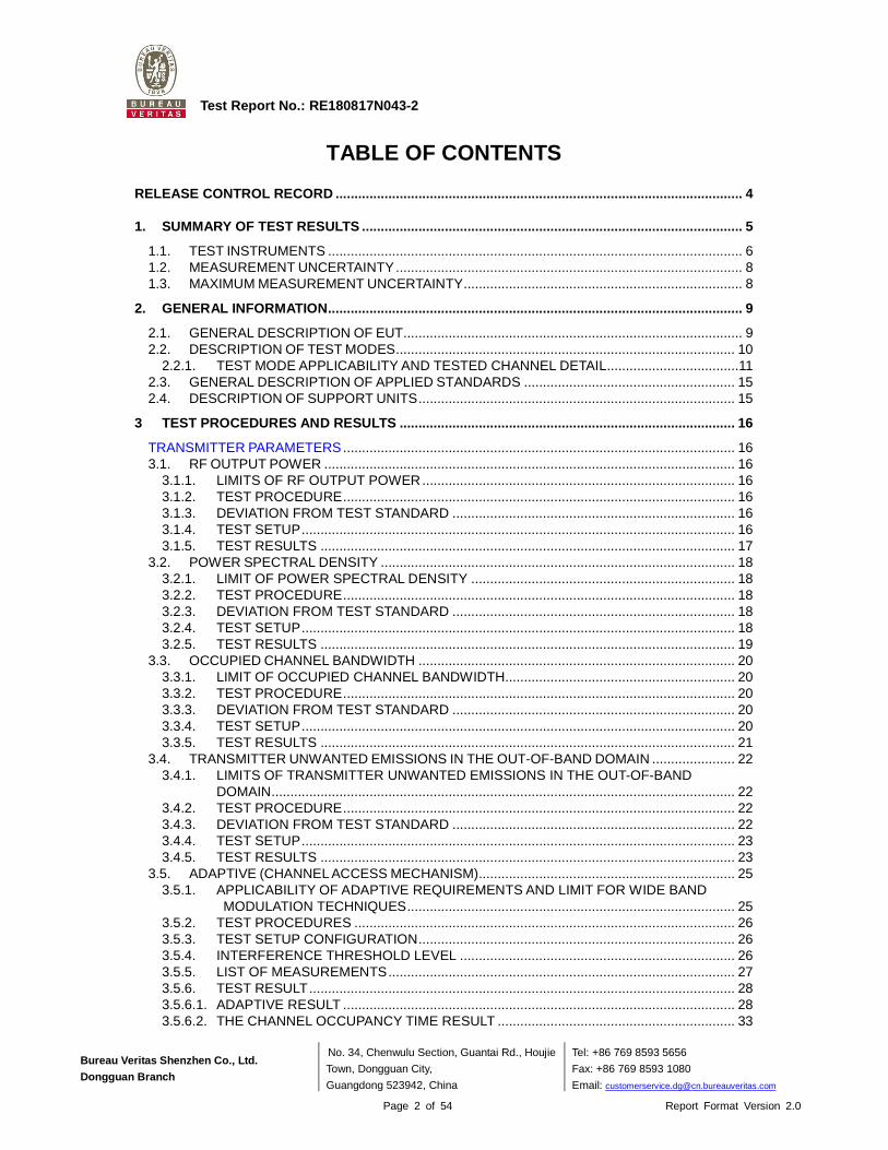
TABLE OF CONTENTS
RELEASE CONTROL RECORD ............................ ................................................................................ 4
1. SUMMARY OF TEST RESULTS ........................... .......................................................................... 5
1.1. TEST INSTRUMENTS .............................................................................................................. 6 1.2. MEASUREMENT UNCERTAINTY ............................................................................................ 8 1.3. MAXIMUM MEASUREMENT UNCERTAINTY .......................................................................... 8
2. GENERAL INFORMATION ............................... ............................................................................... 9
2.1. GENERAL DESCRIPTION OF EUT .......................................................................................... 9 2.2. DESCRIPTION OF TEST MODES .......................................................................................... 10
2.2.1. TEST MODE APPLICABILITY AND TESTED CHANNEL DETAIL ................................... 11 2.3. GENERAL DESCRIPTION OF APPLIED STANDARDS ........................................................ 15 2.4. DESCRIPTION OF SUPPORT UNITS .................................................................................... 15
3 TEST PROCEDURES AND RESULTS ..................... .................................................................... 16
TRANSMITTER PARAMETERS ........................................................................................................ 16 3.1. RF OUTPUT POWER ............................................................................................................. 16
3.1.1. LIMITS OF RF OUTPUT POWER ................................................................................... 16 3.1.2. TEST PROCEDURE ........................................................................................................ 16 3.1.3. DEVIATION FROM TEST STANDARD ........................................................................... 16 3.1.4. TEST SETUP ................................................................................................................... 16 3.1.5. TEST RESULTS .............................................................................................................. 17
3.2. POWER SPECTRAL DENSITY .............................................................................................. 18 3.2.1. LIMIT OF POWER SPECTRAL DENSITY ...................................................................... 18 3.2.2. TEST PROCEDURE ........................................................................................................ 18 3.2.3. DEVIATION FROM TEST STANDARD ........................................................................... 18 3.2.4. TEST SETUP ................................................................................................................... 18 3.2.5. TEST RESULTS .............................................................................................................. 19
3.3. OCCUPIED CHANNEL BANDWIDTH .................................................................................... 20 3.3.1. LIMIT OF OCCUPIED CHANNEL BANDWIDTH ............................................................. 20 3.3.2. TEST PROCEDURE ........................................................................................................ 20 3.3.3. DEVIATION FROM TEST STANDARD ........................................................................... 20 3.3.4. TEST SETUP ................................................................................................................... 20 3.3.5. TEST RESULTS .............................................................................................................. 21
3.4. TRANSMITTER UNWANTED EMISSIONS IN THE OUT-OF-BAND DOMAIN ...................... 22 3.4.1. LIMITS OF TRANSMITTER UNWANTED EMISSIONS IN THE OUT-OF-BAND
DOMAIN ........................................................................................................................... 22 3.4.2. TEST PROCEDURE ........................................................................................................ 22 3.4.3. DEVIATION FROM TEST STANDARD ........................................................................... 22 3.4.4. TEST SETUP ................................................................................................................... 23 3.4.5. TEST RESULTS .............................................................................................................. 23
3.5. ADAPTIVE (CHANNEL ACCESS MECHANISM) .................................................................... 25 3.5.1. APPLICABILITY OF ADAPTIVE REQUIREMENTS AND LIMIT FOR WIDE BAND
MODULATION TECHNIQUES ....................................................................................... 25 3.5.2. TEST PROCEDURES ..................................................................................................... 26 3.5.3. TEST SETUP CONFIGURATION .................................................................................... 26 3.5.4. INTERFERENCE THRESHOLD LEVEL ......................................................................... 26 3.5.5. LIST OF MEASUREMENTS ............................................................................................ 27 3.5.6. TEST RESULT ................................................................................................................. 28 3.5.6.1. ADAPTIVE RESULT ........................................................................................................ 28 3.5.6.2. THE CHANNEL OCCUPANCY TIME RESULT ............................................................... 33

Bureau Veritas Shenzhen Co., Ltd.
Dongguan Branch
No. 34, Chenwulu Section, Guantai Rd., Houjie
Town, Dongguan City,
Guangdong 523942, China
Tel: +86 769 8593 5656
Fax: +86 769 8593 1080
Email: [email protected]
Page 3 of 54 Report Format Version 2.0
Test Report No.: RE180817N043-2
3.6. TRANSMITTER SPURIOUS EMISSIONS .............................................................................. 37 3.6.1. LIMITS OF TRANSMITTER SPURIOUS EMISSIONS .................................................... 37 3.6.2. TEST PROCEDURE ........................................................................................................ 37 3.6.3. DEVIATION FROM TEST STANDARD ........................................................................... 38 3.6.4. TEST SETUP ................................................................................................................... 38 3.6.5. TEST RESULTS .............................................................................................................. 39
RECEIVER PARAMETERS ............................................................................................................... 43 3.7. RECEIVER SPURIOUS RADIATION ...................................................................................... 43
3.7.1. LIMITS OF RECEIVER SPURIOUS RADIATION ........................................................... 43 3.7.2. TEST PROCEDURE ........................................................................................................ 43 3.7.3. DEVIATION FROM TEST STANDARD ........................................................................... 43 3.7.4. TEST SETUP ................................................................................................................... 43 3.7.5. TEST RESULTS .............................................................................................................. 44
3.8. RECEIVER BLOCKING .......................................................................................................... 47 3.8.1. LIMITS OF RECEIVER BLOCKING ................................................................................ 47 3.8.2. TEST PROCEDURE ........................................................................................................ 48 3.8.3. DEVIATION FROM TEST STANDARD ........................................................................... 48 3.8.4. TEST SETUP CONFIGURATION .................................................................................... 49 3.8.5. TEST RESULT ................................................................................................................. 50
4 PHOTOGRAPHS OF THE TEST CONFIGURATION .......... ........................................................... 52
5 APPENDIX A – MODIFICATIONS RECORDERS FOR ENGINEE RING CHANGES TO THE EUT BY THE LAB ........................................ ............................................................................................ 54

Bureau Veritas Shenzhen Co., Ltd.
Dongguan Branch
No. 34, Chenwulu Section, Guantai Rd., Houjie
Town, Dongguan City,
Guangdong 523942, China
Tel: +86 769 8593 5656
Fax: +86 769 8593 1080
Email: [email protected]
Page 4 of 54 Report Format Version 2.0
Test Report No.: RE180817N043-2
RELEASE CONTROL RECORD
ISSUE NO. REASON FOR CHANGE DATE ISSUED
RE180817N043-2 Original release Nov. 30, 2018

Bureau Veritas Shenzhen Co., Ltd.
Dongguan Branch
No. 34, Chenwulu Section, Guantai Rd., Houjie
Town, Dongguan City,
Guangdong 523942, China
Tel: +86 769 8593 5656
Fax: +86 769 8593 1080
Email: [email protected]
Page 5 of 54 Report Format Version 2.0
Test Report No.: RE180817N043-2
1. SUMMARY OF TEST RESULTS
The EUT has been tested according to the following specifications:
EN 300 328 V2.1.1
Clause Test Parameter Results
TRANSMITTER PARAMETERS
4.3.2.2 RF Output Power Pass
4.3.2.3 Power Spectral Density Pass
4.3.2.6 Adaptivity Pass
4.3.2.7 Occupied Channel Bandwidth Pass
4.3.2.8 Transmitter unwanted emission in the OOB
domain Pass
4.3.2.9 Transmitter unwanted emissions in the
spurious domain Pass
4.3.2.12 Geo-location capability Not Applicable
RECEIVER PARAMETERS
4.3.2.10 Receiver Spurious Emissions Pass
4.3.2.11 Receiver Blocking Pass

Bureau Veritas Shenzhen Co., Ltd.
Dongguan Branch
No. 34, Chenwulu Section, Guantai Rd., Houjie
Town, Dongguan City,
Guangdong 523942, China
Tel: +86 769 8593 5656
Fax: +86 769 8593 1080
Email: [email protected]
Page 6 of 54 Report Format Version 2.0
Test Report No.: RE180817N043-2
1.1. TEST INSTRUMENTS
Equipment Manufacturer Model No. Serial No. Last Cal. Next Cal.
EMI Test Receiver Rohde&Schwarz ESU40 100449 Mar. 21,18 Mar. 20,19 Signal and Spectrum Analyzer
Rohde&Schwarz FSV40 101094 Mar. 21,18 Mar. 20,19
Bilog Antenna Teseq CBL 6111D 30643 Aug. 11, 18 Aug. 10, 19
Horn Antenna ETS-Lindgren 3117 00062558 Jul. 21, 18 Jul. 20, 19 GPS Generator+ Antenna
TOJOIN GNSS-5000A E1-010119 Sep. 08,18 Sep. 07,19
3m Semi-anechoic Chamber
ETS-LINDGREN 9m*6m*6m NSEMC003 Feb. 10,18 Feb. 09,19
Test Software ADT ADT_Radiated_V7.6.15.9.2
N/A N/A N/A
Horn Antenna (15GHz-40GHz)
SCHWARZBECK BBHA 9170 BBHA9170147 May 05,18 May 04,19
Amplifier Burgeon BPA-530 100220 Apr. 18,18 Apr. 18,19 Broadband Preamplifier (1GHz~18GHz)
SCHWARZBECK BBV9718 305 Apr. 18,18 Apr. 18,19
Pre-Amplifier (18GHz-40GHz)
EMCI EMC 184045 980102 Nov. 08,17 Nov. 07,18
Power Sensor Keysight U2021XA MY55060016 Jun. 13,18 Jun. 12,19 Power Sensor Keysight U2021XA MY55060018 Jun. 13,18 Jun. 12,19 Digital Multimeter FLUKE 15B A1220010DG Oct. 21, 18 Oct.20, 19 Humid & Temp Programmable Tester Haida HD-2257 110807201 Sep.05, 18 Sep. 04,19
Oscilloscope Agilent DSO9254A MY51260160 Nov. 08,17 Nov. 07,18 Signal and Spectrum Analyzer
Rohde&Schwarz FSV7 102331 Nov. 04,17 Nov. 03,18
Spectrum Analyzer Keysight N9020A MY55400499 Mar. 21,18 Mar. 20,19
Signal Generator Agilent N5183A MY50140980 Jan. 02,18 Jan. 01,19
MXG-B RF Vector Signal Generator
Keysight N5182B MY56200288 Jan. 02,18 Jan. 01,19
Wireless Connectivity Tester
Rohde&Schwarz CMW270 100908 Jan. 10, 18 Jan. 09, 19
Vector Signal Generator
Rohde&Schwarz SMBV100A 257199 Jun. 13,18 Jun. 12,19
Attenuator MINI BW-S10W2+ S130129FGE2 N/A N/A
NOTE: 1. The test was performed in 966 Chamber and RF Oven room. 2. The calibration interval of the above test instruments is 12 months and the calibrations are
traceable to CEPREI/CHINA, GRGT/CHINA and NIM/CHINA. 3. The horn antenna is used only for the measurement of emission frequency above 1GHz if
tested.
Bureau Veritas Shenzhen Co., Ltd.
Dongguan Branch
No. 34, Chenwulu Section, Guantai Rd., Houjie
Town, Dongguan City,
Guangdong 523942, China
Tel: +86 769 8593 5656
Fax: +86 769 8593 1080
Email: [email protected]
Page 7 of 54 Report Format Version 2.0
Test Report No.: RE180817N043-2
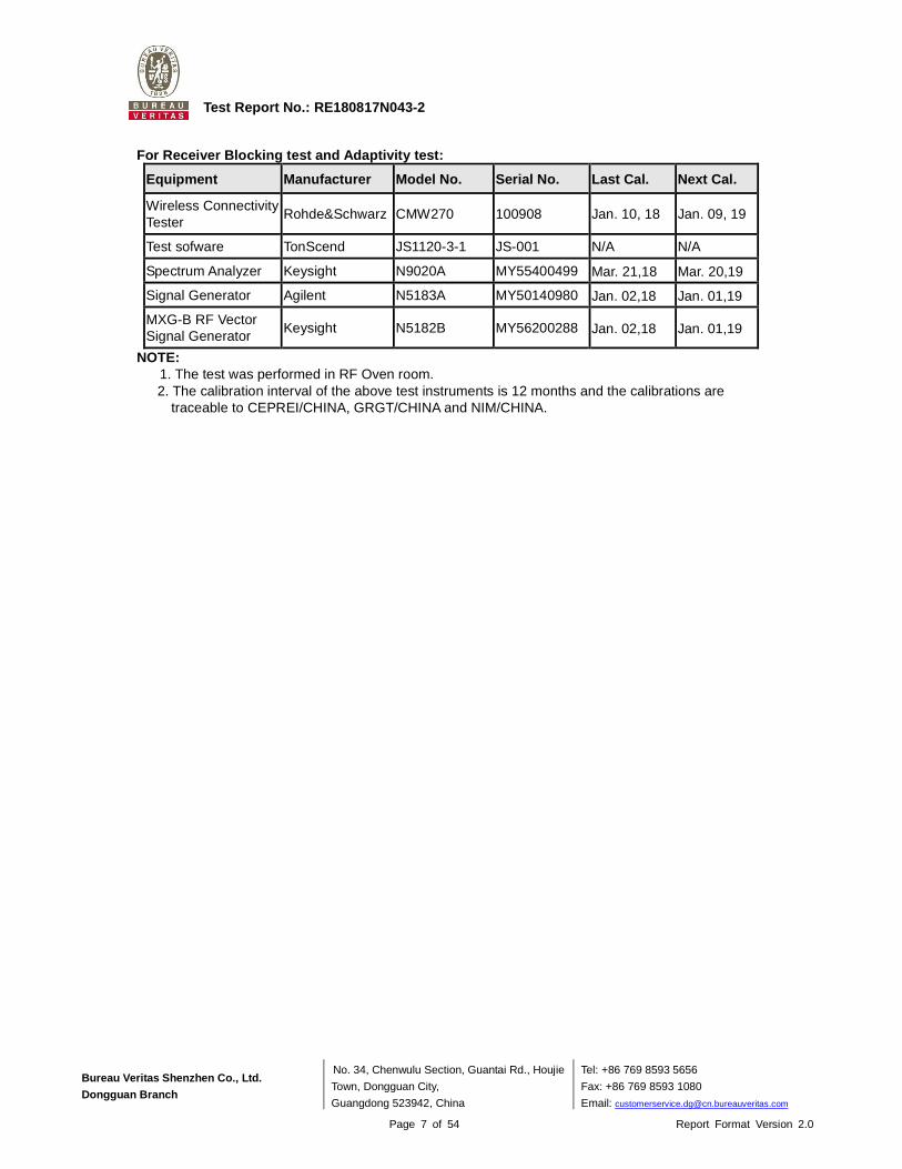
For Receiver Blocking test and Adaptivity test:
Equipment Manufacturer Model No. Serial No. Last Cal. Next Cal.
Wireless Connectivity Tester
Rohde&Schwarz CMW270 100908 Jan. 10, 18 Jan. 09, 19
Test sofware TonScend JS1120-3-1 JS-001 N/A N/A
Spectrum Analyzer Keysight N9020A MY55400499 Mar. 21,18 Mar. 20,19
Signal Generator Agilent N5183A MY50140980 Jan. 02,18 Jan. 01,19
MXG-B RF Vector Signal Generator
Keysight N5182B MY56200288 Jan. 02,18 Jan. 01,19
NOTE: 1. The test was performed in RF Oven room. 2. The calibration interval of the above test instruments is 12 months and the calibrations are
traceable to CEPREI/CHINA, GRGT/CHINA and NIM/CHINA.

Bureau Veritas Shenzhen Co., Ltd.
Dongguan Branch
No. 34, Chenwulu Section, Guantai Rd., Houjie
Town, Dongguan City,
Guangdong 523942, China
Tel: +86 769 8593 5656
Fax: +86 769 8593 1080
Email: [email protected]
Page 8 of 54 Report Format Version 2.0
Test Report No.: RE180817N043-2
1.2. MEASUREMENT UNCERTAINTY
Where relevant, the following measurement uncertainty levels have been estimated for tests performed on the EUT: This uncertainty represents an expanded uncertainty expressed at approximately the 95% confidence level using a coverage factor of k=2.
EN 300 328
Parameter Uncertainty Occupied Channel Bandwidth ±1.132 % RF output power, conducted ±0.56dB Power Spectral Density, conducted ±1.017dB Unwanted Emissions, conducted ±1.017dB All emissions, radiated ±4.84dB Temperature ±0.23°C Supply voltages ±0.1 % Time ±4 %
1.3. MAXIMUM MEASUREMENT UNCERTAINTY
For the test methods, according to ETSI EN 300 328 standard, the measurement uncertainty figures shall be calculated in accordance with ETR 100 028-1 [4] and shall correspond to an expansion factor (coverage factor) k = 1,96 or k = 2 (which provide confidence levels of respectively 95 % and 95,45 % in the case where the distributions characterizing the actual measurement uncertainties are normal (Gaussian)).
Maximum measurement uncertainty
Parameter Uncertainty Occupied Channel Bandwidth ±5 % RF output power, conducted ±1,5 dB Power Spectral Density, conducted ±3 dB Unwanted Emissions, conducted ±3 dB All emissions, radiated ±6 dB Temperature ±3 °C Supply voltages ±3 % Time ±5 %

Bureau Veritas Shenzhen Co., Ltd.
Dongguan Branch
No. 34, Chenwulu Section, Guantai Rd., Houjie
Town, Dongguan City,
Guangdong 523942, China
Tel: +86 769 8593 5656
Fax: +86 769 8593 1080
Email: [email protected]
Page 9 of 54 Report Format Version 2.0
Test Report No.: RE180817N043-2
2. GENERAL INFORMATION
2.1. GENERAL DESCRIPTION OF EUT
PRODUCT
TEST MODEL ARGN
ADDITIONAL MODELS N/A
NOMINAL VOLTAGE Li+ PIN /Battery connector: DC 3.7V from Li-ion Battery or VUSB PIN /USB connector :DC 5V from USB Host Unit
OPERATING TEMPERATURE RNAGE -20 ~ +80℃
MODULATION TECHNOLOGY DSSS, OFDM
MODULATION TYPE CCK, DQPSK, DBPSK for DSSS 64QAM, 16QAM, QPSK, BPSK for OFDM
OPERATING FREQUENCY 2412-2472MHz for 11b/g/n(HT20) 2422-2462MHz for 11n(HT40)
ADPTIVE/NON-ADPTIVE
non-adaptive Equipment
adaptive Equipment without the possibility to switch to a
non-adaptive mode adaptive Equipment which can also operate in a
non-adaptive mode
EIRP POWER (MAX.) 18.05dBm (Measured Max.)
ANTENNA TYPE FPCB Antenna, 2dBi Gain
CABLE SUPPLIED N/A
Note:
1. The above EUT information is declared by manufacturer and for more detailed features description, please refer to the manufacturer's specifications or user's manual.
2. For the test results, the EUT had been tested with all conditions, but only the worst case was shown in test report.
3. Please refer to the EUT photo document (Reference No.: 180817N043) for detailed product photo.
4. The EUT is wireless module, it no any accessories.
5. The EUT have SISO function, provides 1 completed transmitters and 1 receivers.
MODULATION MODE TX FUNCTION
802.11b 1TX/1RX
802.11g 1TX/1RX
802.11n (HT20) 1TX/1RX
802.11n (HT40) 1TX/1RX
Argon

Bureau Veritas Shenzhen Co., Ltd.
Dongguan Branch
No. 34, Chenwulu Section, Guantai Rd., Houjie
Town, Dongguan City,
Guangdong 523942, China
Tel: +86 769 8593 5656
Fax: +86 769 8593 1080
Email: [email protected]
Page 10 of 54 Report Format Version 2.0
Test Report No.: RE180817N043-2
2.2. DESCRIPTION OF TEST MODES
13 channels are provided for 802.11b, 802.11g and 802.11n (HT20): CHANNEL FREQUENCY CHANNEL FREQUENCY
1 2412 MHz 8 2447 MHz
2 2417 MHz 9 2452 MHz
3 2422 MHz 10 2457 MHz
4 2427 MHz 11 2462 MHz
5 2432 MHz 12 2467 MHz
6 2437 MHz 13 2472 MHz
7 2442 MHz
9 channels are provided for 802.11n (HT40): CHANNEL FREQUENCY CHANNEL FREQUENCY
3 2422 MHz 8 2447 MHz
4 2427 MHz 9 2452 MHz
5 2432 MHz 10 2457 MHz
6 2437 MHz 11 2462 MHz
7 2442 MHz

Bureau Veritas Shenzhen Co., Ltd.
Dongguan Branch
No. 34, Chenwulu Section, Guantai Rd., Houjie
Town, Dongguan City,
Guangdong 523942, China
Tel: +86 769 8593 5656
Fax: +86 769 8593 1080
Email: [email protected]
Page 11 of 54 Report Format Version 2.0
Test Report No.: RE180817N043-2
2.2.1. TEST MODE APPLICABILITY AND TESTED CHANNEL DETAIL
EUT
CONFIGURE
MODE
APPLICABLE TO
DESCRIPTION ROP PSD AD OCB OOB RSE<1G RSE≥1G RB
A √ √ - √ √ √ √ √ Powered by Fully Battery
B - - - - - - - - Powered by Adapter
Where ROP: RF Output Power PSD: Power Spectral Density
AD: Adaptivity (Channel Access Mechanism) OCB: Occupied Channel Bandwidth
OOB: Transmitter unwanted emissioin in the
out-of-band domain
RSE<1G: Spurious Emissions below 1GHz
RSE≥1G: Spurious Emissions above 1GHz RB: Receiver Blocking
RF OUTPUT POWER TEST: Pre-Scan has been conducted to determine the worst-case mode from all possible combinations
between available modulations, data rates and antenna ports (if EUT with antenna diversity architecture).
Following channel(s) was (were) selected for the final test as listed below.
POWER SPECTRAL DENSITY TEST: Pre-Scan has been conducted to determine the worst-case mode from all possible combinations
between available modulations, data rates and antenna ports (if EUT with antenna diversity architecture).
Following channel(s) was (were) selected for the final test as listed below.
MODE AVAILABLE
CHANNEL
TESTED
CHANNEL
MODULATION
TECHNOLOGY
MODULATION
TYPE
DATA RATE
(Mbps)
802.11b 1 to 13 1, 7, 13 DSSS DBPSK 1.0
802.11g 1 to 13 1, 7, 13 OFDM BPSK 6.0
802.11n (HT20) 1 to 13 1, 7, 13 OFDM BPSK 6.5
802.11n (HT40) 3 to 11 3, 7, 11 OFDM BPSK 13.5
MODE AVAILABLE
CHANNEL
TESTED
CHANNEL
MODULATION
TECHNOLOGY
MODULATION
TYPE
DATA RATE
(Mbps)
802.11b 1 to 13 1, 7, 13 DSSS DBPSK 1.0
802.11g 1 to 13 1, 7, 13 OFDM BPSK 6.0
802.11n (HT20) 1 to 13 1, 7, 13 OFDM BPSK 6.5
802.11n (HT40) 3 to 11 3, 7, 11 OFDM BPSK 13.5
Bureau Veritas Shenzhen Co., Ltd.
Dongguan Branch
No. 34, Chenwulu Section, Guantai Rd., Houjie
Town, Dongguan City,
Guangdong 523942, China
Tel: +86 769 8593 5656
Fax: +86 769 8593 1080
Email: [email protected]
Page 12 of 54 Report Format Version 2.0
Test Report No.: RE180817N043-2
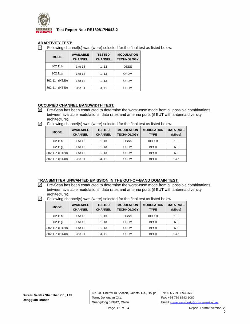
ADAPTIVITY TEST:
Following channel(s) was (were) selected for the final test as listed below.
OCCUPIED CHANNEL BANDWIDTH TEST: Pre-Scan has been conducted to determine the worst-case mode from all possible combinations
between available modulations, data rates and antenna ports (if EUT with antenna diversity architecture).
Following channel(s) was (were) selected for the final test as listed below.
TRANSMITTER UNWANTED EMISSION IN THE OUT-OF-BAND DO MAIN TEST: Pre-Scan has been conducted to determine the worst-case mode from all possible combinations
between available modulations, data rates and antenna ports (if EUT with antenna diversity architecture).
Following channel(s) was (were) selected for the final test as listed below.
MODE AVAILABLE
CHANNEL
TESTED
CHANNEL
MODULATION
TECHNOLOGY
802.11b 1 to 13 1, 13 DSSS
802.11g 1 to 13 1, 13 OFDM
802.11n (HT20) 1 to 13 1, 13 OFDM
802.11n (HT40) 3 to 11 3, 11 OFDM
MODE AVAILABLE
CHANNEL
TESTED
CHANNEL
MODULATION
TECHNOLOGY
MODULATION
TYPE
DATA RATE
(Mbps)
802.11b 1 to 13 1, 13 DSSS DBPSK 1.0
802.11g 1 to 13 1, 13 OFDM BPSK 6.0
802.11n (HT20) 1 to 13 1, 13 OFDM BPSK 6.5
802.11n (HT40) 3 to 11 3, 11 OFDM BPSK 13.5
MODE AVAILABLE
CHANNEL
TESTED
CHANNEL
MODULATION
TECHNOLOGY
MODULATION
TYPE
DATA RATE
(Mbps)
802.11b 1 to 13 1, 13 DSSS DBPSK 1.0
802.11g 1 to 13 1, 13 OFDM BPSK 6.0
802.11n (HT20) 1 to 13 1, 13 OFDM BPSK 6.5
802.11n (HT40) 3 to 11 3, 11 OFDM BPSK 13.5

Bureau Veritas Shenzhen Co., Ltd.
Dongguan Branch
No. 34, Chenwulu Section, Guantai Rd., Houjie
Town, Dongguan City,
Guangdong 523942, China
Tel: +86 769 8593 5656
Fax: +86 769 8593 1080
Email: [email protected]
Page 13 of 54 Report Format Version 2.0
Test Report No.: RE180817N043-2
SPURIOUS EMISSIONS TEST (BELOW 1 GHZ): Pre-Scan has been conducted to determine the worst-case mode from all possible combinations
between available modulations, data rates and antenna ports (if EUT with antenna diversity architecture).
Following channel(s) was (were) selected for the final test as listed below.
SPURIOUS EMISSIONS TEST (ABOVE 1 GHZ): Pre-Scan has been conducted to determine the worst-case mode from all possible combinations
between available modulations, data rates and antenna ports (if EUT with antenna diversity architecture).
Following channel(s) was (were) selected for the final test as listed below.
RECEIVER BLOCKING TEST:
Following channel(s) was (were) selected for the final test as listed below.
MODE AVAILABLE
CHANNEL
TESTED
CHANNEL
MODULATION
TECHNOLOGY
MODULATION
TYPE
DATA RATE
(Mbps)
802.11b 1 to 13 1, 13 DSSS DBPSK 1.0
MODE AVAILABLE
CHANNEL
TESTED
CHANNEL
MODULATION
TECHNOLOGY
MODULATION
TYPE
DATA RATE
(Mbps)
802.11b 1 to 13 1 DSSS DBPSK 1
Receiver 1 to 13 1 - - -
MODE AVAILABLE
CHANNEL
TESTED
CHANNEL
MODULATION
TECHNOLOGY
MODULATION
TYPE
DATA RATE
(Mbps)
802.11b 1 to 13 1, 13 DSSS DBPSK 1.0
802.11g 1 to 13 1, 13 OFDM BPSK 6.0
802.11n (HT20) 1 to 13 1, 13 OFDM BPSK 6.5
802.11n (HT40) 3 to 11 3, 11 OFDM BPSK 13.5
Receiver 1 to 13 1, 13 - - -

Bureau Veritas Shenzhen Co., Ltd.
Dongguan Branch
No. 34, Chenwulu Section, Guantai Rd., Houjie
Town, Dongguan City,
Guangdong 523942, China
Tel: +86 769 8593 5656
Fax: +86 769 8593 1080
Email: [email protected]
Page 14 of 54 Report Format Version 2.0
Test Report No.: RE180817N043-2
TEST CONDITION:
APPLICABLE
TO ENVIRONMENTAL CONDITIONS INPUT POWER TESTED BY
ROP 25deg. C, 60%RH DC 3.7V from Fully Battery Sen He
PSD 25deg. C, 60%RH DC 3.7V from Fully Battery Sen He
AD 25deg. C, 60%RH DC 3.7V from Fully Battery Sen He
OCB 25deg. C, 60%RH DC 3.7V from Fully Battery Sen He
OOB 25deg. C, 60%RH DC 3.7V from Fully Battery Sen He
RSE<1G 25deg. C, 55%RH DC 3.7V from Fully Battery Arnold
RSE≥1G 25deg. C, 55%RH DC 3.7V from Fully Battery Arnold
RB 25deg. C, 60%RH DC 3.7V from Fully Battery Sen He

Bureau Veritas Shenzhen Co., Ltd.
Dongguan Branch
No. 34, Chenwulu Section, Guantai Rd., Houjie
Town, Dongguan City,
Guangdong 523942, China
Tel: +86 769 8593 5656
Fax: +86 769 8593 1080
Email: [email protected]
Page 15 of 54 Report Format Version 2.0
Test Report No.: RE180817N043-2
2.3. GENERAL DESCRIPTION OF APPLIED STANDARDS
The EUT is a RF product, according to the specifications of the manufacturers. It must comply with the requirements of the following standards:
EN 300 328 V2.1.1 (2016-11)
All test items have been performed and recorded as per the above standards.
2.4. DESCRIPTION OF SUPPORT UNITS
The EUT has been tested as an independent unit together with other necessary accessories or support units. The following support units or accessories were used to form a representative test configuration during the tests.
NO. PRODUCT BRAND MODEL NO. SERIAL NO. FCC ID 1 DC source LONG WEI PS-6403D 010934269 N/A 2 Li-ion Battery N/A DC3.7V N/A N/A
NO. SIGNAL CABLE DESCRIPTION OF THE ABOVE SUPPORT UNITS 1 DC Line: Unshielded, Detachable 1.0m 2 N/A
NOTE: All power cords of the above support units are non-shielded (1.8m).

Bureau Veritas Shenzhen Co., Ltd.
Dongguan Branch
No. 34, Chenwulu Section, Guantai Rd., Houjie
Town, Dongguan City,
Guangdong 523942, China
Tel: +86 769 8593 5656
Fax: +86 769 8593 1080
Email: [email protected]
Page 16 of 54 Report Format Version 2.0
Test Report No.: RE180817N043-2
3 TEST PROCEDURES AND RESULTS
TRANSMITTER PARAMETERS
3.1. RF OUTPUT POWER
3.1.1. LIMITS OF RF OUTPUT POWER
CONDITION FREQUENCY BAND LIMIT (e.i.r.p.)
Under all test conditions 2400 ~ 2483.5 MHz AV: 20dBm
3.1.2. TEST PROCEDURE
Refer to chapter 5.4.2.2 of ETSI EN 300 328 V2.1.1.
Measurement
Conducted measurement Radiated measurement
3.1.3. DEVIATION FROM TEST STANDARD
No deviation.
3.1.4. TEST SETUP
The measurement was performed at both normal environmental conditions and at the extremes of the operating temperature. The measurement was performed at the lowest, the middle, and the highest channel. The equipment was configured to operate under its worst case situation with respect to output power. (In case of conducted measurements the transmitter shall be connected to the measuring equipment via a suitable attenuator.) Controlling software has been activated to set the EUT on specific channel and power level.

Bureau Veritas Shenzhen Co., Ltd.
Dongguan Branch
No. 34, Chenwulu Section, Guantai Rd., Houjie
Town, Dongguan City,
Guangdong 523942, China
Tel: +86 769 8593 5656
Fax: +86 769 8593 1080
Email: [email protected]
Page 17 of 54 Report Format Version 2.0
Test Report No.: RE180817N043-2
3.1.5. TEST RESULTS
TEST CONDITION
EIRP POWER (dBm)
(CH1) 2412 MHz
(CH7) 2442 MHz
(CH13) 2472 MHz
802.11b
Tnom(℃) +25
Vnom(v)
17.69 16.72 16.24
Tmin(℃) -20 18.05 16.89 16.58
Tmax(℃) +80 17.39 16.35 15.75
802.11g
Tnom(℃) +25
Vnom(v)
15.75 15.49 14.95
Tmin(℃) -20 15.86 15.83 15.25
Tmax(℃) +80 15.59 14.94 14.43
802.11n (HT20)
Tnom(℃) +25
Vnom(v)
15.72 15.31 15.04
Tmin(℃) -20 15.73 15.58 15.38
Tmax(℃) +80 15.20 14.80 14.34
TEST CONDITION
EIRP POWER (dBm)
(CH3) 2422 MHz
(CH7) 2442 MHz
(CH11) 2462 MHz
802.11n (HT40)
Tnom(℃) +25
Vnom(v)
15.67 15.36 15.24
Tmin(℃) -20 15.90 15.60 15.48
Tmax(℃) +80 15.09 14.91 15.02
NOTE: EIRP = Conducted output power + ANT Gain.

Bureau Veritas Shenzhen Co., Ltd.
Dongguan Branch
No. 34, Chenwulu Section, Guantai Rd., Houjie
Town, Dongguan City,
Guangdong 523942, China
Tel: +86 769 8593 5656
Fax: +86 769 8593 1080
Email: [email protected]
Page 18 of 54 Report Format Version 2.0
Test Report No.: RE180817N043-2
3.2. POWER SPECTRAL DENSITY
3.2.1. LIMIT OF POWER SPECTRAL DENSITY
CONDITION FREQUENCY BAND LIMIT (e.i.r.p.)
Under normal conditions 2400 ~ 2483.5 MHz 10dBm / 1MHz
3.2.2. TEST PROCEDURE
Refer to chapter 5.4.3.2 of ETSI EN 300 328 V2.1.1.
Measurement Method
Conducted measurement Radiated measurement
Option 1: For equipment with continuous and non-continuous transmissions
Option 2: For equipment with continuous transmission capability or for equipment operating (or with the capability to operate) with a constant duty cycle (e.g. Frame Based equipment)
3.2.3. DEVIATION FROM TEST STANDARD
No deviation.
3.2.4. TEST SETUP
The measurement was performed at normal environmental conditions only. The measurement was performed at the lowest, the middle, and the highest channel. The equipment was configured to operate under its worst case situation with respect to output power. (In case of conducted measurements the transmitter shall be connected to the measuring equipment via a suitable attenuator.) Controlling software has been activated to set the EUT on specific status.

Bureau Veritas Shenzhen Co., Ltd.
Dongguan Branch
No. 34, Chenwulu Section, Guantai Rd., Houjie
Town, Dongguan City,
Guangdong 523942, China
Tel: +86 769 8593 5656
Fax: +86 769 8593 1080
Email: [email protected]
Page 19 of 54 Report Format Version 2.0
Test Report No.: RE180817N043-2
3.2.5. TEST RESULTS
802.11b
CHANNEL CHANNEL
FREQUENCY (MHz)
POWER DENSITY (dBm/1MHz)
(E.I.R.P)
LIMIT (dBm/1MHz)
(E.I.R.P) PASS/FAIL
1 2412.00 8.75 10 PASS
7 2442.00 7.77 10 PASS
13 2472.00 7.28 10 PASS
802.11g
CHANNEL CHANNEL
FREQUENCY (MHz)
POWER DENSITY (dBm/1MHz)
(E.I.R.P)
LIMIT (dBm/1MHz)
(E.I.R.P) PASS/FAIL
1 2412.00 4.18 10 PASS
7 2442.00 3.94 10 PASS
13 2472.00 3.42 10 PASS
802.11n (HT20)
CHANNEL CHANNEL
FREQUENCY (MHz)
POWER DENSITY (dBm/1MHz)
(E.I.R.P)
LIMIT (dBm/1MHz)
(E.I.R.P) PASS/FAIL
1 2412.00 7.49 10 PASS
7 2442.00 7.96 10 PASS
13 2472.00 7.75 10 PASS
802.11n (HT40)
CHANNEL CHANNEL
FREQUENCY (MHz)
POWER DENSITY (dBm/1MHz)
(E.I.R.P)
LIMIT (dBm/1MHz)
(E.I.R.P) PASS/FAIL
3 2422.00 0.70 10 PASS
7 2442.00 0.49 10 PASS
11 2462.00 0.42 10 PASS

Bureau Veritas Shenzhen Co., Ltd.
Dongguan Branch
No. 34, Chenwulu Section, Guantai Rd., Houjie
Town, Dongguan City,
Guangdong 523942, China
Tel: +86 769 8593 5656
Fax: +86 769 8593 1080
Email: [email protected]
Page 20 of 54 Report Format Version 2.0
Test Report No.: RE180817N043-2
3.3. OCCUPIED CHANNEL BANDWIDTH
3.3.1. LIMIT OF OCCUPIED CHANNEL BANDWIDTH
CONDITION LIMIT
All types of equipment Shall fall completely within the band 2400 to 2483.5 MHz.
Additional requirement
For non-adaptive using wide band modulations other than FHSS system and e.i.r.p >10dBm.
Less than 20MHz
For non-adaptive Frequency Hopping system and e.i.r.p
>10dBm. Less than 5MHz
3.3.2. TEST PROCEDURE
Refer to chapter 5.4.7.2 of ETSI EN 300 328 V2.1.1.
Measurement
Conducted measurement Radiated measurement
3.3.3. DEVIATION FROM TEST STANDARD
No deviation. 3.3.4. TEST SETUP
The measurement was performed at normal environmental conditions only. This measurement was performed at the lowest and the highest channel. The equipment was configured to operate under its worst case situation with respect to output power. (In case of conducted measurements the transmitter shall be connected to the measuring equipment via a suitable attenuator.) Controlling software has been activated to set the EUT on specific status.

Bureau Veritas Shenzhen Co., Ltd.
Dongguan Branch
No. 34, Chenwulu Section, Guantai Rd., Houjie
Town, Dongguan City,
Guangdong 523942, China
Tel: +86 769 8593 5656
Fax: +86 769 8593 1080
Email: [email protected]
Page 21 of 54 Report Format Version 2.0
Test Report No.: RE180817N043-2
3.3.5. TEST RESULTS
802.11b
CHANNEL CHANNEL
FREQUENCY (MHz)
OCCUPIED BANDWIDTH
(MHZ)
Measured frequencies LIMIT PASS/FAIL
FL (MHz) FH (MHz)
1 2412 13.28 2405.36 2418.64 FL > 2400 MHz and
FH < 2483.5 MHz
PASS
13 2472 13.28 2465.36 2478.64 PASS
802.11g
CHANNEL CHANNEL
FREQUENCY (MHz)
OCCUPIED BANDWIDTH
(MHZ)
Measured frequencies LIMIT PASS/FAIL
FL (MHz) FH (MHz)
1 2412 17.12 2403.44 2420.56 FL > 2400 MHz and
FH < 2483.5 MHz
PASS
13 2472 17.04 2463.44 2480.48 PASS
802.11n(HT20)
CHANNEL CHANNEL
FREQUENCY (MHz)
OCCUPIED BANDWIDTH
(MHZ)
Measured frequencies LIMIT PASS/FAIL
FL (MHz) FH (MHz)
1 2412 17.92 2403.04 2420.96 FL > 2400 MHz and
FH < 2483.5 MHz
PASS
13 2472 17.92 2463.04 2480.96 PASS
802.11n(HT40)
CHANNEL CHANNEL
FREQUENCY (MHz)
OCCUPIED BANDWIDTH
(MHZ)
Measured frequencies LIMIT PASS/FAIL
FL (MHz) FH (MHz)
3 2422 36.48 2403.76 2440.24 FL > 2400 MHz and
FH < 2483.5 MHz
PASS
11 2462 36.48 2443.76 2480.24 PASS
Note: FL is the lowest frequency of the 99% occupied bandwidth of power envelope. FH is the highest frequency of the 99% occupied bandwidth of power envelope.

Bureau Veritas Shenzhen Co., Ltd.
Dongguan Branch
No. 34, Chenwulu Section, Guantai Rd., Houjie
Town, Dongguan City,
Guangdong 523942, China
Tel: +86 769 8593 5656
Fax: +86 769 8593 1080
Email: [email protected]
Page 22 of 54 Report Format Version 2.0
Test Report No.: RE180817N043-2
3.4. TRANSMITTER UNWANTED EMISSIONS IN THE OUT-OF-B AND DOMAIN
3.4.1. LIMITS OF TRANSMITTER UNWANTED EMISSIONS IN THE OUT-OF-BAND DOMAIN
CONDITION LIMIT
Under all test conditions The transmitter unwanted emissions in the out-of-band domain but outside the allocated band, shall not exceed the values provided by the mask in below figure.
3.4.2. TEST PROCEDURE
Refer to chapter 5.4.8.2 of ETSI EN 300 328 V2.1.1.
Measurement
Conducted measurement Radiated measurement
3.4.3. DEVIATION FROM TEST STANDARD
No deviation.

Bureau Veritas Shenzhen Co., Ltd.
Dongguan Branch
No. 34, Chenwulu Section, Guantai Rd., Houjie
Town, Dongguan City,
Guangdong 523942, China
Tel: +86 769 8593 5656
Fax: +86 769 8593 1080
Email: [email protected]
Page 23 of 54 Report Format Version 2.0
Test Report No.: RE180817N043-2
3.4.4. TEST SETUP
The measurement was performed at normal environmental conditions only. This measurement was performed at the lowest and the highest channel. The equipment was configured to operate under its worst case situation with respect to output power. (In case of conducted measurements the transmitter shall be connected to the measuring equipment via a suitable attenuator.) The frequency has to be recorded for the right and left end above threshold of highest and lowest channel respectively.
3.4.5. TEST RESULTS
802.11b
CHANNEL FREQ.(MHz) 2412 2472
TEST CONDITION
OOB Emission (MHz) OOB Emission (MHz)
2386.72 ~ 2400
2373.44 ~ 2386.72
2483.5 ~ 2496.78
2496.78 ~ 2510.06
Temperature Voltage Freq. (MHz)
Power (dBm)
Freq. (MHz)
Power (dBm)
Freq. (MHz)
Power (dBm)
Freq. (MHz)
Power (dBm)
Tnorm(℃) 25 Normal 2399.50 -44.01 2386.22 -52.66 2484.00 -41.27 2497.28 -53.78
Limit (dBm/MHz) -10.00 -20.00 -10.00 -20.00
PASS/FAIL PASS PASS PASS PASS
802.11g
CHANNEL FREQ.(MHz) 2412 2472
TEST CONDITION
OOB Emission (MHz) OOB Emission (MHz)
2382.88 ~ 2400
2365.76 ~ 2382.88
2483.5 ~ 2500.54
2500.54 ~ 2517.58
Temperature Voltage Freq. (MHz)
Power (dBm)
Freq. (MHz)
Power (dBm)
Freq. (MHz)
Power (dBm)
Freq. (MHz)
Power (dBm)
Tnorm(℃) 25 Normal 2399.50 -32.95 2382.38 -47.80 2484.00 -31.85 2501.12 -48.31
Limit (dBm/MHz) -10.00 -20.00 -10.00 -20.00
PASS/FAIL PASS PASS PASS PASS
Bureau Veritas Shenzhen Co., Ltd.
Dongguan Branch
No. 34, Chenwulu Section, Guantai Rd., Houjie
Town, Dongguan City,
Guangdong 523942, China
Tel: +86 769 8593 5656
Fax: +86 769 8593 1080
Email: [email protected]
Page 24 of 54 Report Format Version 2.0
Test Report No.: RE180817N043-2
802.11n (HT20)
CHANNEL FREQ.(MHz) 2412 2472
TEST CONDITION
OOB Emission (MHz) OOB Emission (MHz)
2382.08 ~ 2400
2364.16 ~ 2382.08
2483.5 ~ 2501.42
2501.42 ~ 2519.34
Temperature Voltage Freq. (MHz)
Power (dBm)
Freq. (MHz)
Power (dBm)
Freq. (MHz)
Power (dBm)
Freq. (MHz)
Power (dBm)
Tnorm(℃) 25 Normal 2399.50 -33.98 2381.58 -48.50 2484.00 -31.58 2501.92 -49.27
Limit (dBm/MHz) -10.00 -20.00 -10.00 -20.00
PASS/FAIL PASS PASS PASS PASS
802.11n (HT40)
CHANNEL FREQ.(MHz) 2422 2462
TEST CONDITION
OOB Emission (MHz) OOB Emission (MHz)
2363.52 ~ 2400
2327.04 ~ 2363.52
2483.5 ~ 2519.98
2519.98 ~ 2556.46
Temperature Voltage Freq. (MHz)
Power (dBm)
Freq. (MHz)
Power (dBm)
Freq. (MHz)
Power (dBm)
Freq. (MHz)
Power (dBm)
Tnorm(℃) 25 Normal 2399.50 -29.13 2363.02 -48.44 2484.00 -29.81 2520.48 -49.94
Limit (dBm/MHz) -10.00 -20.00 -10.00 -20.00
PASS/FAIL PASS PASS PASS PASS
Bureau Veritas Shenzhen Co., Ltd.
Dongguan Branch
No. 34, Chenwulu Section, Guantai Rd., Houjie
Town, Dongguan City,
Guangdong 523942, China
Tel: +86 769 8593 5656
Fax: +86 769 8593 1080
Email: [email protected]
Page 25 of 54 Report Format Version 2.0
Test Report No.: RE180817N043-2
3.5. ADAPTIVE (CHANNEL ACCESS MECHANISM)
3.5.1. APPLICABILITY OF ADAPTIVE REQUIREMENTS AND LIMIT FOR WIDE BAND MODULATION TECHNIQUES
Requirement
Operational Mode
Non-LBT based
Detect and Avoid
LBT based Detect and Avoid
Frame Based Equipment
Load Based Equipment
(CCA using 'energy
detect')
Load Based Equipment
(CCA not using any of the
mechanisms referenced as
note 2) Minimum Clear Channel Assessment (CCA) Time NA 18 us (see note 1) (see note 2) 18 us (see note 1)
Maximum Channel Occupancy (COT) Time 40 ms 1 ms to 10 ms (see note 2) 13 ms
Minimum Idle Period 5us 5% of COT (see note 2) 18us (see note 3) Extended CCA check NA NA (see note 2) 18us~160us
Short Control Signalling Transmissions
Maximum duty cycle of 10 % within an observation period of 50 ms (see note 4)
NOTE 1: The CCA time used by the equipment shall be declared by the supplier. NOTE 2:Load Based Equipment may implement an LBT based spectrum sharing mechanism based on the Clear
ChannelAssessment (CCA) mode using energy detect, as described in IEEE 802.11™-2012 clause 9, clause 10, clause 16,clause 17, clause 19 and clause 20, or in IEEE 802.15.4™-2011 [i.4], clause 4, clause 5 and clause 8
NOTE 3: The Idle Period in between transmissions is considered to be the CCA or the Extended CCA check as there are no transmissions during this period.
NOTE 4: Adaptive equipment may or may not have Short Control Signalling Transmissions
Interference threshold level
Maximum transmit power (P H) EIRP dBm
Threshold level (TL) (see notes 1 and 2)
20 -70 dBm / MHz
NOTE 1: For a 20 dBm e.i.r.p. transmitter the CCA threshold level (TL) shall be equal to or less than -70 dBm/MHz at the input to the receiver assuming a 0 dBi (receive) antenna assembly. This threshold level (TL) may be corrected for the (receive) antenna assembly gain (G)
NOTE 2: For power levels less than 20 dBm e.i.r.p. the CCA threshold level may be relaxed to: TL = -70 dBm/MHz + 10 × log10 (100 mW / Pout) ; (Pout in mW e.i.r.p.)
Wanted signal mean power from companion device
Unwanted signal frequency (MHz)
Unwanted signal power (dBm)
sufficient to maintain the link (see note 2)
2 395 or 2 488,5 (see note 1)
-35 (see note 3)
NOTE 1: The highest frequency shall be used for testing operating channels within the range 2 400 MHz to 2 442 MHz, while the lowest frequency shall be used for testing operating channels within the range 2 442 MHz to 2 483,5 MHz. See clause 5.4.6.1.
NOTE 2: A typical value which can be used in most cases is -50 dBm/MHz. NOTE 3: The level specified is the level in front of the UUT antenna. In case of conducted measurements, this level
has to be corrected by the actual antenna assembly gain.
Bureau Veritas Shenzhen Co., Ltd.
Dongguan Branch
No. 34, Chenwulu Section, Guantai Rd., Houjie
Town, Dongguan City,
Guangdong 523942, China
Tel: +86 769 8593 5656
Fax: +86 769 8593 1080
Email: [email protected]
Page 26 of 54 Report Format Version 2.0
Test Report No.: RE180817N043-2
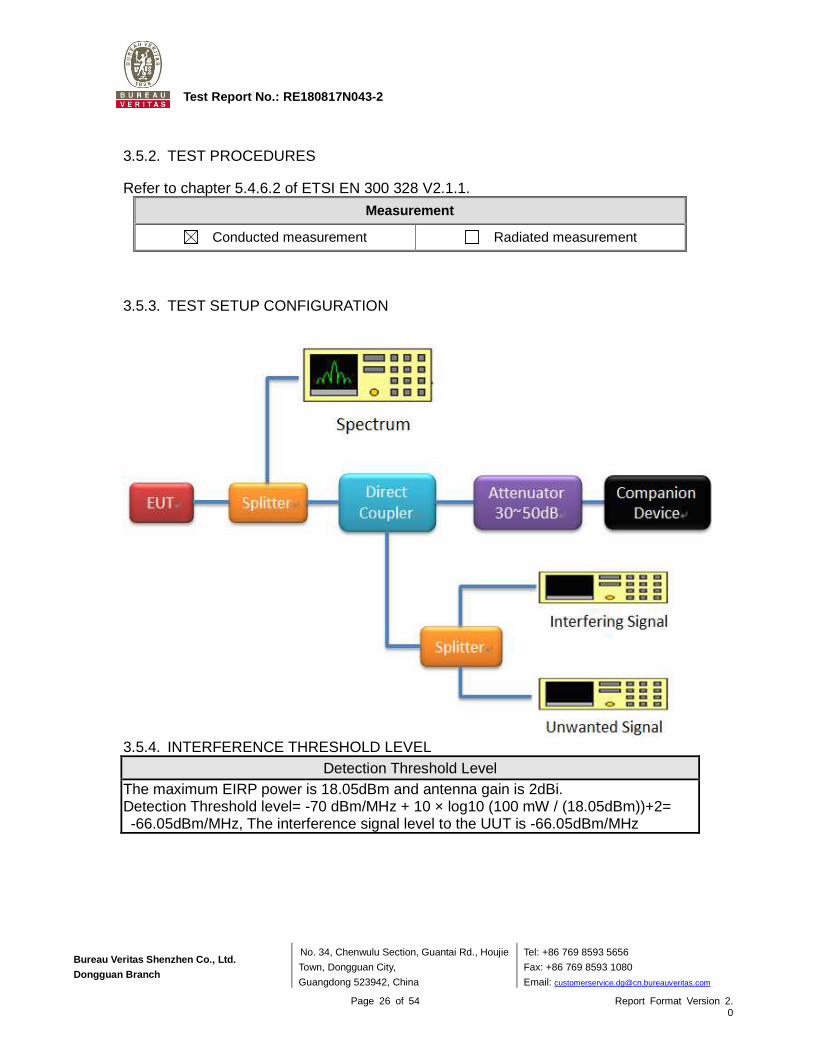
3.5.2. TEST PROCEDURES
Refer to chapter 5.4.6.2 of ETSI EN 300 328 V2.1.1.
Measurement
Conducted measurement Radiated measurement
3.5.3. TEST SETUP CONFIGURATION
3.5.4. INTERFERENCE THRESHOLD LEVEL
Detection Threshold Level The maximum EIRP power is 18.05dBm and antenna gain is 2dBi. Detection Threshold level= -70 dBm/MHz + 10 × log10 (100 mW / (18.05dBm))+2= -66.05dBm/MHz, The interference signal level to the UUT is -66.05dBm/MHz

Bureau Veritas Shenzhen Co., Ltd.
Dongguan Branch
No. 34, Chenwulu Section, Guantai Rd., Houjie
Town, Dongguan City,
Guangdong 523942, China
Tel: +86 769 8593 5656
Fax: +86 769 8593 1080
Email: [email protected]
Page 27 of 54 Report Format Version 2.0
Test Report No.: RE180817N043-2
3.5.5. LIST OF MEASUREMENTS
UUT Operational Mode
Applicable
Limit The Maximum
Channel Occupancy Time
The Minimum idle Period
Frame Based Equipment meet in 1ms ~ 10ms >5% x channel
occupancy time
Load Based Equipment (Base on
'Spectrum Sharing' mechanisms)
Follow IEEE 802.11 Less than _____ms
Follow IEEE 802.11 More than _____ms
Load Based Equipment
(Not using any of the mechanisms
referenced)
v 13ms 18us
Clause Test Parameter Remarks Pass/Fail
4.3.2.6.3.2.2 Adaptive (Frame Based Equipment) Not Applicable NA
4.3.2.6.3.2.3 Adaptive (Load Based Equipment) Applicable Pass
4.3.2.6.4 Short Control Signalling Transmissions
Applicable Pass
Bureau Veritas Shenzhen Co., Ltd.
Dongguan Branch
No. 34, Chenwulu Section, Guantai Rd., Houjie
Town, Dongguan City,
Guangdong 523942, China
Tel: +86 769 8593 5656
Fax: +86 769 8593 1080
Email: [email protected]
Page 28 of 54 Report Format Version 2.0
Test Report No.: RE180817N043-2
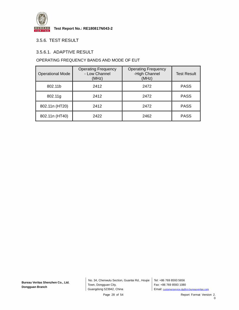
3.5.6. TEST RESULT
3.5.6.1. ADAPTIVE RESULT
OPERATING FREQUENCY BANDS AND MODE OF EUT
Operational Mode Operating Frequency
- Low Channel (MHz)
Operating Frequency -High Channel
(MHz) Test Result
802.11b 2412 2472 PASS
802.11g 2412 2472 PASS
802.11n (HT20) 2412 2472 PASS
802.11n (HT40) 2422 2462 PASS

Bureau Veritas Shenzhen Co., Ltd.
Dongguan Branch
No. 34, Chenwulu Section, Guantai Rd., Houjie
Town, Dongguan City,
Guangdong 523942, China
Tel: +86 769 8593 5656
Fax: +86 769 8593 1080
Email: [email protected]
Page 29 of 54 Report Format Version 2.0
Test Report No.: RE180817N043-2
802.11b
2412MHz
2472MHz
Max. TxOn: 1.10 ms; Duty cycle: 2.2%

Bureau Veritas Shenzhen Co., Ltd.
Dongguan Branch
No. 34, Chenwulu Section, Guantai Rd., Houjie
Town, Dongguan City,
Guangdong 523942, China
Tel: +86 769 8593 5656
Fax: +86 769 8593 1080
Email: [email protected]
Page 30 of 54 Report Format Version 2.0
Test Report No.: RE180817N043-2
802.11g
2412MHz
2472MHz
Max. TxOn: 1.20ms; Duty cycle: 2.4%

Bureau Veritas Shenzhen Co., Ltd.
Dongguan Branch
No. 34, Chenwulu Section, Guantai Rd., Houjie
Town, Dongguan City,
Guangdong 523942, China
Tel: +86 769 8593 5656
Fax: +86 769 8593 1080
Email: [email protected]
Page 31 of 54 Report Format Version 2.0
Test Report No.: RE180817N043-2
802.11n(HT20)
2412MHz
2472MHz
Max. TxOn: 0.00ms; Duty cycle: 0%

Bureau Veritas Shenzhen Co., Ltd.
Dongguan Branch
No. 34, Chenwulu Section, Guantai Rd., Houjie
Town, Dongguan City,
Guangdong 523942, China
Tel: +86 769 8593 5656
Fax: +86 769 8593 1080
Email: [email protected]
Page 32 of 54 Report Format Version 2.0
Test Report No.: RE180817N043-2
802.11n(HT40) 2422MHz
2462MHz
Max. TxOn: 0.50ms; Duty cycle: 1%

Bureau Veritas Shenzhen Co., Ltd.
Dongguan Branch
No. 34, Chenwulu Section, Guantai Rd., Houjie
Town, Dongguan City,
Guangdong 523942, China
Tel: +86 769 8593 5656
Fax: +86 769 8593 1080
Email: [email protected]
Page 33 of 54 Report Format Version 2.0
Test Report No.: RE180817N043-2
3.5.6.2. THE CHANNEL OCCUPANCY TIME RESULT
802.11b mode
The Channel occupancy Time: 0.053ms
Minimum idle time: 0.114ms

Bureau Veritas Shenzhen Co., Ltd.
Dongguan Branch
No. 34, Chenwulu Section, Guantai Rd., Houjie
Town, Dongguan City,
Guangdong 523942, China
Tel: +86 769 8593 5656
Fax: +86 769 8593 1080
Email: [email protected]
Page 34 of 54 Report Format Version 2.0
Test Report No.: RE180817N043-2
802.11g mode
The Channel occupancy Time: 0.048ms
Minimum idle time: 0.125ms

Bureau Veritas Shenzhen Co., Ltd.
Dongguan Branch
No. 34, Chenwulu Section, Guantai Rd., Houjie
Town, Dongguan City,
Guangdong 523942, China
Tel: +86 769 8593 5656
Fax: +86 769 8593 1080
Email: [email protected]
Page 35 of 54 Report Format Version 2.0
Test Report No.: RE180817N043-2
802.11nHT20 mode
The Channel occupancy Time: 0.037ms
Minimum idle time: 0.279ms

Bureau Veritas Shenzhen Co., Ltd.
Dongguan Branch
No. 34, Chenwulu Section, Guantai Rd., Houjie
Town, Dongguan City,
Guangdong 523942, China
Tel: +86 769 8593 5656
Fax: +86 769 8593 1080
Email: [email protected]
Page 36 of 54 Report Format Version 2.0
Test Report No.: RE180817N043-2
802.11nHT40 mode
The Channel occupancy Time: 0.103ms
Minimum idle time: 0.053ms

Bureau Veritas Shenzhen Co., Ltd.
Dongguan Branch
No. 34, Chenwulu Section, Guantai Rd., Houjie
Town, Dongguan City,
Guangdong 523942, China
Tel: +86 769 8593 5656
Fax: +86 769 8593 1080
Email: [email protected]
Page 37 of 54 Report Format Version 2.0
Test Report No.: RE180817N043-2
3.6. TRANSMITTER SPURIOUS EMISSIONS
3.6.1. LIMITS OF TRANSMITTER SPURIOUS EMISSIONS
Transmitter limits for narrowband spurious emissions:
Frequency Range Maximum Power Limit
(e.r.p. (≤ 1 GHz) e.i.r.p. (> 1 GHz))
Bandwidth
30 MHz to 47 MHz -36dBm 100kHz
47 MHz to 74 MHz -54dBm 100kHz
74 MHz to 87,5 MHz -36dBm 100kHz
87,5 MHz to 118 MHz -54dBm 100kHz
118 MHz to 174 MHz -36dBm 100kHz
174 MHz to 230 MHz -54dBm 100kHz
230 MHz to 470 MHz -36dBm 100kHz
470 MHz to 862 MHz -54dBm 100kHz
862 MHz to 1 GHz -36dBm 100kHz
1GHz ~ 12.75GHz -30dBm 1MHz
Note: These limits are e.r.p. for emissions up to 1 GHz and as e.i.r.p. for emissions above 1 GHz.
3.6.2. TEST PROCEDURE
Refer to chapter 5.4.9.2 of ETSI EN 300 328 V2.1.1.
Measurement
Conducted measurement Radiated measurement
For Conducted measurement:
The level of unwanted emissions shall be measured as their power in a specified load (conducted spurious emissions) and their effective radiated power when radiated by the cabinet or structure of the equipment with the antenna connector(s) terminated by a specified load (cabinet radiation).
Conducted measurement (For equipment with multiple transmit chains):
Option 1: The results for each of the transmit chains for the corresponding 1MHz segments shall be added and compared with the limits.
Option 2: The results for each of the transmit chains shall be individually compared with
the limits after these limits have been reduced by 10 x log (N) (number of active transmit
chains)
Bureau Veritas Shenzhen Co., Ltd.
Dongguan Branch
No. 34, Chenwulu Section, Guantai Rd., Houjie
Town, Dongguan City,
Guangdong 523942, China
Tel: +86 769 8593 5656
Fax: +86 769 8593 1080
Email: [email protected]
Page 38 of 54 Report Format Version 2.0
Test Report No.: RE180817N043-2
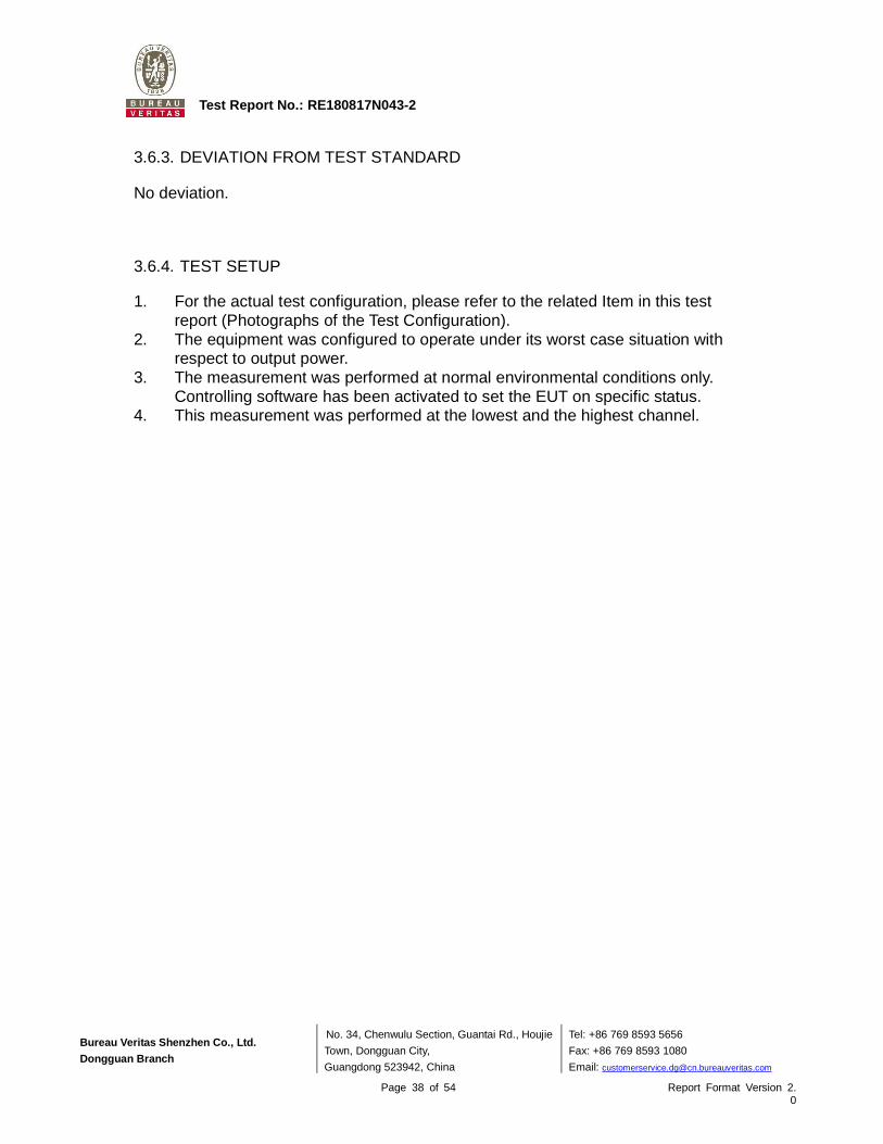
3.6.3. DEVIATION FROM TEST STANDARD
No deviation.
3.6.4. TEST SETUP
1. For the actual test configuration, please refer to the related Item in this test report (Photographs of the Test Configuration).
2. The equipment was configured to operate under its worst case situation with respect to output power.
3. The measurement was performed at normal environmental conditions only. Controlling software has been activated to set the EUT on specific status.
4. This measurement was performed at the lowest and the highest channel.

Bureau Veritas Shenzhen Co., Ltd.
Dongguan Branch
No. 34, Chenwulu Section, Guantai Rd., Houjie
Town, Dongguan City,
Guangdong 523942, China
Tel: +86 769 8593 5656
Fax: +86 769 8593 1080
Email: [email protected]
Page 39 of 54 Report Format Version 2.0
Test Report No.: RE180817N043-2
3.6.5. TEST RESULTS
BELOW 1GHz WORST-CASE DATA
802.11b
FREQUENCY RANGE 30MHz ~ 1GHz OPERATING CHANNEL 1
SPURIOUS EMISSION LEVEL
Frequency (MHz)
Antenna Polarization
Level (dBm)
Limit (dBm)
Margin (dB)
187.82 H -73.35 -54.00 -19.35
232.44 H -70.76 -36.00 -34.76
598.00 H -72.90 -54.00 -18.90
689.28 H -72.54 -54.00 -18.54
747.80 H -70.96 -54.00 -16.96
828.08 H -69.08 -54.00 -15.08

Bureau Veritas Shenzhen Co., Ltd.
Dongguan Branch
No. 34, Chenwulu Section, Guantai Rd., Houjie
Town, Dongguan City,
Guangdong 523942, China
Tel: +86 769 8593 5656
Fax: +86 769 8593 1080
Email: [email protected]
Page 40 of 54 Report Format Version 2.0
Test Report No.: RE180817N043-2
FREQUENCY RANGE 30MHz ~ 1GHz OPERATING CHANNEL 1
SPURIOUS EMISSION LEVEL
Frequency (MHz)
Antenna Polarization
Level (dBm)
Limit (dBm)
Margin (dB)
519.98 V -75.05 -54.00 -21.05
617.27 V -72.94 -54.00 -18.94
676.31 V -72.84 -54.00 -18.84
741.69 V -71.51 -54.00 -17.51
777.45 V -71.63 -54.00 -17.63
826.43 V -70.53 -54.00 -16.53

Bureau Veritas Shenzhen Co., Ltd.
Dongguan Branch
No. 34, Chenwulu Section, Guantai Rd., Houjie
Town, Dongguan City,
Guangdong 523942, China
Tel: +86 769 8593 5656
Fax: +86 769 8593 1080
Email: [email protected]
Page 41 of 54 Report Format Version 2.0
Test Report No.: RE180817N043-2
ABOVE 1GHz WORST-CASE DATA
802.11b
FREQUENCY RANGE 1GHz ~ 12.75GHz OPERATING CHANNEL 1, 13
SPURIOUS EMISSION LEVEL
Channel Frequency
(MHz) Antenna
Polarization Level (dBm)
Limit (dBm)
Margin (dB)
1
4824.00 H -48.08 -30.00 -18.08
4824.23 V -50.09 -30.00 -20.09
7236.00 H -51.43 -30.00 -21.43
7236.00 V -54.27 -30.00 -24.27
13
4944.00 V -48.66 -30.00 -18.66
4944.08 H -41.90 -30.00 -11.90
9888.00 V -46.13 -30.00 -16.13
9888.09 H -42.82 -30.00 -12.82
802.11g
FREQUENCY RANGE 1GHz ~ 12.75GHz OPERATING CHANNEL 1, 13
SPURIOUS EMISSION LEVEL
Channel Frequency
(MHz) Antenna
Polarization Level (dBm)
Limit (dBm)
Margin (dB)
1
4824.00 H -55.10 -30.00 -25.10
4824.00 V -56.81 -30.00 -26.81
7236.00 H -51.34 -30.00 -21.34
7236.00 V -53.78 -30.00 -23.78
13
4944.00 V -55.70 -30.00 -25.70
4944.08 H -48.41 -30.00 -18.41
7416.00 H -51.26 -30.00 -21.26
7416.00 V -52.06 -30.00 -22.06

Bureau Veritas Shenzhen Co., Ltd.
Dongguan Branch
No. 34, Chenwulu Section, Guantai Rd., Houjie
Town, Dongguan City,
Guangdong 523942, China
Tel: +86 769 8593 5656
Fax: +86 769 8593 1080
Email: [email protected]
Page 42 of 54 Report Format Version 2.0
Test Report No.: RE180817N043-2
802.11n (HT20)
FREQUENCY RANGE 1GHz ~ 12.75GHz OPERATING CHANNEL 1, 13
SPURIOUS EMISSION LEVEL
Channel Frequency
(MHz) Antenna
Polarization Level (dBm)
Limit (dBm)
Margin (dB)
1
4824.00 H -56.95 -30.00 -26.95
4824.00 V -56.28 -30.00 -26.28
7236.00 H -53.18 -30.00 -23.18
7236.00 V -52.09 -30.00 -22.09
13
4942.52 H -50.66 -30.00 -20.66
4944.00 V -56.20 -30.00 -26.20
7416.00 H -51.45 -30.00 -21.45
7416.00 V -51.26 -30.00 -21.26
802.11n (HT40)
FREQUENCY RANGE 1GHz ~ 12.75GHz OPERATING CHANNEL 3, 11
SPURIOUS EMISSION LEVEL
Channel Frequency
(MHz) Antenna
Polarization Level (dBm)
Limit (dBm)
Margin (dB)
3
4844.00 H -55.65 -30.00 -25.65
4844.00 V -55.71 -30.00 -25.71
7266.00 H -52.91 -30.00 -22.91
7266.00 V -53.93 -30.00 -23.93
11
4917.45 H -51.50 -30.00 -21.50
4924.00 V -57.25 -30.00 -27.25
7386.00 H -51.32 -30.00 -21.32
7386.00 V -51.99 -30.00 -21.99

Bureau Veritas Shenzhen Co., Ltd.
Dongguan Branch
No. 34, Chenwulu Section, Guantai Rd., Houjie
Town, Dongguan City,
Guangdong 523942, China
Tel: +86 769 8593 5656
Fax: +86 769 8593 1080
Email: [email protected]
Page 43 of 54 Report Format Version 2.0
Test Report No.: RE180817N043-2
RECEIVER PARAMETERS
3.7. RECEIVER SPURIOUS RADIATION
3.7.1. LIMITS OF RECEIVER SPURIOUS RADIATION
Frequency Range Maximum Power Limit
(e.r.p. (≤ 1 GHz) e.i.r.p. (> 1 GHz))
30MHz ~ 1GHz -57dBm
1GHz ~ 12.75GHz -47dBm
Note: These limits are e.r.p. for emissions up to 1 GHz and as e.i.r.p. for emissions above 1 GHz.
3.7.2. TEST PROCEDURE
Refer to chapter 5.4.10.2 of ETSI EN 300 328 V2.1.1.
Measurement
Conducted measurement Radiated measurement
For Conducted measurement: The level of unwanted emissions shall be measured as their power in a specified load (conducted spurious emissions) and their effective radiated power when radiated by the cabinet or structure of the equipment with the antenna connector(s) terminated by a specified load (cabinet radiation).
Conducted measurement (For equipment with multiple transmit chains): Option 1: The results for each of the transmit chains for the corresponding 1MHz
segments shall be added and compared with the limits. Option 2: The results for each of the transmit chains shall be individually compared with
the limits after these limits have been reduced by 10 x log (N) (number of active transmit chains)
3.7.3. DEVIATION FROM TEST STANDARD
No deviation.
3.7.4. TEST SETUP
1. For the actual test configuration, please refer to the related Item in this test report (Photographs of the Test Configuration).
2. Testing was performed when the equipment was in a receive-only mode. 3. The measurement was performed at normal environmental conditions only.
Controlling software has been activated to set the EUT on specific status. 4. This measurement was performed at the lowest and the highest channel.

Bureau Veritas Shenzhen Co., Ltd.
Dongguan Branch
No. 34, Chenwulu Section, Guantai Rd., Houjie
Town, Dongguan City,
Guangdong 523942, China
Tel: +86 769 8593 5656
Fax: +86 769 8593 1080
Email: [email protected]
Page 44 of 54 Report Format Version 2.0
Test Report No.: RE180817N043-2
3.7.5. TEST RESULTS
RX WORST-CASE DATA
FREQUENCY RANGE 30MHz ~ 1GHz OPERATING CHANNEL 1
SPURIOUS EMISSION LEVEL
Frequency (MHz)
Antenna Polarization
Level (dBm)
Limit (dBm)
Margin (dB)
241.40 H -71.25 -57.00 -14.25
268.43 H -74.82 -57.00 -17.82
645.92 H -72.91 -57.00 -15.91
811.01 H -71.18 -57.00 -14.18
879.43 H -65.23 -57.00 -8.23
943.32 H -67.25 -57.00 -10.25

Bureau Veritas Shenzhen Co., Ltd.
Dongguan Branch
No. 34, Chenwulu Section, Guantai Rd., Houjie
Town, Dongguan City,
Guangdong 523942, China
Tel: +86 769 8593 5656
Fax: +86 769 8593 1080
Email: [email protected]
Page 45 of 54 Report Format Version 2.0
Test Report No.: RE180817N043-2
FREQUENCY RANGE 30MHz ~ 1GHz OPERATING CHANNEL 1
SPURIOUS EMISSION LEVEL
Frequency (MHz)
Antenna Polarization
Level (dBm)
Limit (dBm)
Margin (dB)
119.98 V -79.16 -57.00 -22.16
598.13 V -72.17 -57.00 -15.17
674.02 V -70.60 -57.00 -13.60
769.40 V -71.73 -57.00 -14.73
879.49 V -64.06 -57.00 -7.06
943.35 V -64.68 -57.00 -7.68

Bureau Veritas Shenzhen Co., Ltd.
Dongguan Branch
No. 34, Chenwulu Section, Guantai Rd., Houjie
Town, Dongguan City,
Guangdong 523942, China
Tel: +86 769 8593 5656
Fax: +86 769 8593 1080
Email: [email protected]
Page 46 of 54 Report Format Version 2.0
Test Report No.: RE180817N043-2
RX ABOVE 1GHz DATA
FREQUENCY RANGE 1GHz ~ 12.75GHz OPERATING CHANNEL 1, 13
SPURIOUS EMISSION LEVEL
Channel Frequency
(MHz) Antenna
Polarization Level (dBm)
Limit (dBm)
Margin (dB)
1
4824.00 H -58.59 -47.00 -11.59
4824.00 V -57.48 -47.00 -10.48
7236.00 H -52.21 -47.00 -5.21
7236.00 V -51.47 -47.00 -4.47
13
4944.00 H -54.85 -47.00 -7.85
4944.00 V -56.49 -47.00 -9.49
7416.00 H -51.96 -47.00 -4.96
7416.00 V -50.85 -47.00 -3.85

Bureau Veritas Shenzhen Co., Ltd.
Dongguan Branch
No. 34, Chenwulu Section, Guantai Rd., Houjie
Town, Dongguan City,
Guangdong 523942, China
Tel: +86 769 8593 5656
Fax: +86 769 8593 1080
Email: [email protected]
Page 47 of 54 Report Format Version 2.0
Test Report No.: RE180817N043-2
3.8. RECEIVER BLOCKING
3.8.1. LIMITS OF RECEIVER BLOCKING
This requirement applies to all receiver categories.
Receiver Category
Category 1(EIRP>10dBm) Category 2(EIRP ≦10dBm) Category 3(EIRP ≦0dBm)
Minimum performance criterion PER ≦10%
Alternative performance criteria (See note)
Note: The manufacturer was declared performance criteria is x% for the intended use of the equipment.
Receiver Cate gory 1 Equipment
Wanted signal mean power from companion
device (dBm)
Blocking Signal Frequency
(MHz)
Blocking Signal Power
(dBm) (See note 2)
Type of blocking signal
Pmin + 6 dB 2 380 2 503.5 -53 CW
Pmin + 6 dB 2 300 2 330 2 360
-47 CW
Pmin + 6 dB
2 523.5 2 553.5 2 583.5 2 613.5 2 643.5 2 673.5
-47 CW
NOTE 1: Pmin is the minimum level of the wanted signal (in dBm) required to meet the minimum performance criteria as defined in clause 4.3.2.11.3 in the absence of any blocking signal.
NOTE 2: The levels specified are levels in front of the UUT antenna. In case of conducted measurements, the levels have to be corrected by the actual antenna assembly gain.
Receiver Category 2 Equipment Wanted signal mean power
from companion device (dBm)
Blocking Signal Frequency
(MHz)
Blocking Signal Power
(dBm) (See note 2)
Type of blocking signal
Pmin + 6 dB 2 380 2 503.5 -57 CW
Pmin + 6 dB 2 300 2 583.5 -47 CW
NOTE 1: Pmin is the minimum level of the wanted signal (in dBm) required to meet the minimum performance criteria as defined in clause 4.3.2.11.3 in the absence of any blocking signal.
NOTE 2: The levels specified are levels in front of the UUT antenna. In case of conducted measurements, the levels have to be corrected by the actual antenna assembly gain.
Bureau Veritas Shenzhen Co., Ltd.
Dongguan Branch
No. 34, Chenwulu Section, Guantai Rd., Houjie
Town, Dongguan City,
Guangdong 523942, China
Tel: +86 769 8593 5656
Fax: +86 769 8593 1080
Email: [email protected]
Page 48 of 54 Report Format Version 2.0
Test Report No.: RE180817N043-2
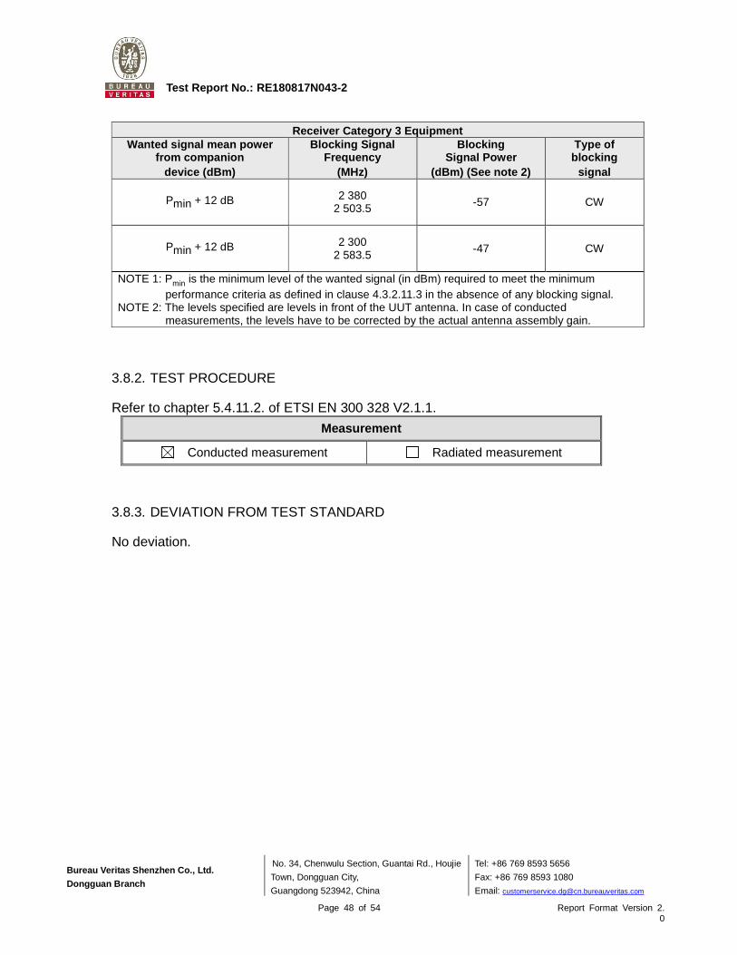
Receiver Cate gory 3 Equipment Wanted signal mean power
from companion device (dBm)
Blocking Signal Frequency
(MHz)
Blocking Signal Power
(dBm) (See note 2)
Type of blocking
signal
Pmin + 12 dB 2 380 2 503.5 -57 CW
Pmin + 12 dB 2 300 2 583.5 -47 CW
NOTE 1: Pmin is the minimum level of the wanted signal (in dBm) required to meet the minimum performance criteria as defined in clause 4.3.2.11.3 in the absence of any blocking signal.
NOTE 2: The levels specified are levels in front of the UUT antenna. In case of conducted measurements, the levels have to be corrected by the actual antenna assembly gain.
3.8.2. TEST PROCEDURE
Refer to chapter 5.4.11.2. of ETSI EN 300 328 V2.1.1.
Measurement
Conducted measurement Radiated measurement
3.8.3. DEVIATION FROM TEST STANDARD
No deviation.

Bureau Veritas Shenzhen Co., Ltd.
Dongguan Branch
No. 34, Chenwulu Section, Guantai Rd., Houjie
Town, Dongguan City,
Guangdong 523942, China
Tel: +86 769 8593 5656
Fax: +86 769 8593 1080
Email: [email protected]
Page 49 of 54 Report Format Version 2.0
Test Report No.: RE180817N043-2
3.8.4. TEST SETUP CONFIGURATION
Direct
Coupler EUT Splitter Attenuator
Spectrum Analyzer
Blocking Signal Generator
Companion
Device
Performance Monitor Device
Attenuator
Bureau Veritas Shenzhen Co., Ltd.
Dongguan Branch
No. 34, Chenwulu Section, Guantai Rd., Houjie
Town, Dongguan City,
Guangdong 523942, China
Tel: +86 769 8593 5656
Fax: +86 769 8593 1080
Email: [email protected]
Page 50 of 54 Report Format Version 2.0
Test Report No.: RE180817N043-2
3.8.5. TEST RESULT
802.11b
Receiver Category 1 Equipment Receiver blocking performance when o perating at the lowest operating channel (CH01)
Pmin: -94.58dBm antenna gain(G) : 2dBi
The actual blocking signal power(Note1) at the antenna connector in front of the antenna
Note1: For the conducted measurements , the level shall be corrected as follows: the actual blocking signal power = blocking signal power + G
Wanted signal mean power from companion device
(dBm)
Blocking signal frequency
(MHz))
The actual blocking signal
power (dBm) PER(%) Pass/Fail
Pmin + 6 dB
2380 -51 0.9 PASS 2503.5 -51 2.1 PASS 2300 -45 1.3 PASS 2330 -45 1 PASS 2360 -45 1.4 PASS
2523.5 -45 1.2 PASS 2553.5 -45 0.9 PASS 2583.5 -45 1 PASS 2613.5 -45 0.8 PASS 2643.5 -45 1.1 PASS 2673.5 -45 1 PASS

Bureau Veritas Shenzhen Co., Ltd.
Dongguan Branch
No. 34, Chenwulu Section, Guantai Rd., Houjie
Town, Dongguan City,
Guangdong 523942, China
Tel: +86 769 8593 5656
Fax: +86 769 8593 1080
Email: [email protected]
Page 51 of 54 Report Format Version 2.0
Test Report No.: RE180817N043-2
Receiver blocking perf ormance when operating at the Highest operating cha nnel (CH13) Pmin: -95.79dBm antenna gain(G) : 2dBi
The actual blocking signal power(Note1) at the antenna connector in front of the antenna
Note1: For the conducted measurements , the level shall be corrected as follows: the actual blocking signal power = blocking signal power + G
Wanted signal mean power from companion device
(dBm)
Blocking signal frequency
(MHz))
The actual blocking signal
power (dBm) PER(%) Pass/Fail
Pmin + 6 dB
2380 -51 0.9 PASS 2503.5 -51 0.6 PASS 2300 -45 0.5 PASS 2330 -45 0.6 PASS 2360 -45 0.1 PASS
2523.5 -45 1 PASS 2553.5 -45 1.5 PASS 2583.5 -45 0.3 PASS 2613.5 -45 0 PASS 2643.5 -45 0.8 PASS 2673.5 -45 0.4 PASS
Bureau Veritas Shenzhen Co., Ltd.
Dongguan Branch
No. 34, Chenwulu Section, Guantai Rd., Houjie
Town, Dongguan City,
Guangdong 523942, China
Tel: +86 769 8593 5656
Fax: +86 769 8593 1080
Email: [email protected]
Page 52 of 54 Report Format Version 2.0
Test Report No.: RE180817N043-2
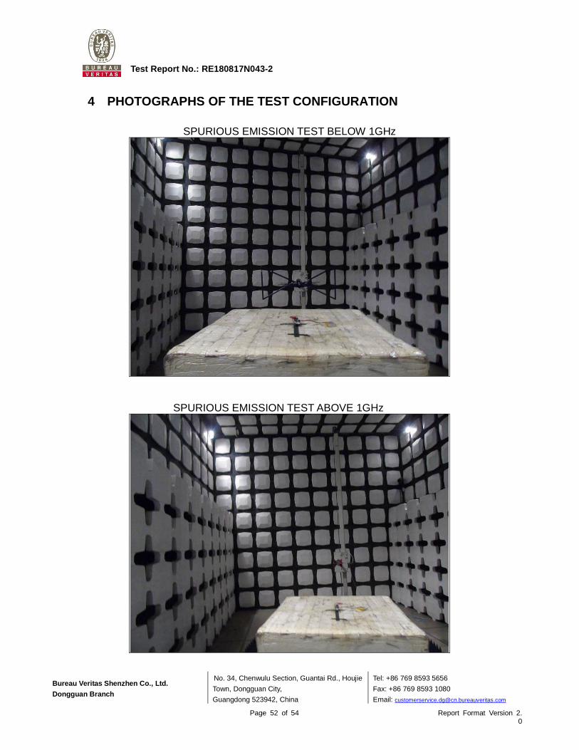
4 PHOTOGRAPHS OF THE TEST CONFIGURATION
SPURIOUS EMISSION TEST BELOW 1GHz
SPURIOUS EMISSION TEST ABOVE 1GHz
Bureau Veritas Shenzhen Co., Ltd.
Dongguan Branch
No. 34, Chenwulu Section, Guantai Rd., Houjie
Town, Dongguan City,
Guangdong 523942, China
Tel: +86 769 8593 5656
Fax: +86 769 8593 1080
Email: [email protected]
Page 53 of 54 Report Format Version 2.0
Test Report No.: RE180817N043-2
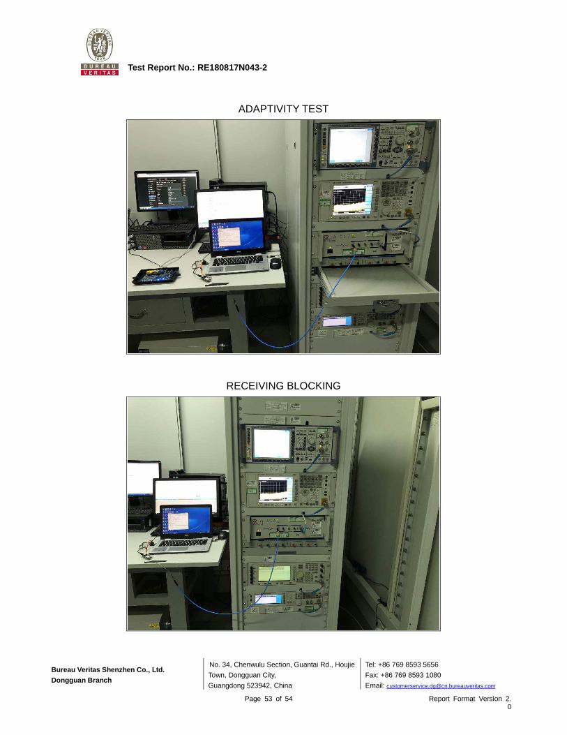
ADAPTIVITY TEST
RECEIVING BLOCKING
Bureau Veritas Shenzhen Co., Ltd.
Dongguan Branch
No. 34, Chenwulu Section, Guantai Rd., Houjie
Town, Dongguan City,
Guangdong 523942, China
Tel: +86 769 8593 5656
Fax: +86 769 8593 1080
Email: [email protected]
Page 54 of 54 Report Format Version 2.0
Test Report No.: RE180817N043-2
5 APPENDIX A – MODIFICATIONS RECORDERS FOR ENGINEERING CHANGES TO THE EUT BY THE LAB
No any modifications were made to the EUT by the lab during the test.
--- END ---