Embed Size (px)
Citation preview
Report No. 103229R-RFCEP39V01
Page: 1 of 38
Test Report
For:Intel Product Name Notebook
Model No. MS-16F1, MS-16F2, MS-16F3, MS-16F4, MS-16F5, MS-16F6, MS-16F7, MS-16F8, MS-16F9, MS-16FA, MS-16FB, MS-16FC, MS-16FD, MS-16FE, MS-16FF, MS-16FG, MS-16FH, MS-16FI, MS-16FJ, MS-16FK, MS-16FL, MS-16FM, MS-16FN, MS-16FO, MS-16FP, MS-16FQ, MS-16FR, MS-16FS, MS-16FT, MS-16FU, MS-16FV, MS-16FW, MS-16FX, MS-16FY, MS-16FZ, GTzzzz (z=0~9,a~z,A~Z or blank), GXzzzz (z=0~9,a~z,A~Z or blank)
Applicant MICRO-STAR INT'L Co., LTD.
Address No. 69, Li-De St., Jung-He City, Taipei Hsien,
Taiwan, R.O.C.
Date of Receipt Mar. 15, 2010
Date of Test Aug. 26, 2010
Report No. 103229R-RFCEP39V01
Report Version V0.1-Draft
The test results relate only to the samples tested.
The test report shall not be reproduced except in full without the written approval of QuieTek Corporation.
Report No. 103229R-RFCEP39V01
Page: 2 of 38
Test Report Cert i f icat ion Date of Test: Aug. 26, 2010 Report No.: 103229R-RFCEP39V01
Product Name Notebook
Applicant MICRO-STAR INT'L Co., LTD.
Address No. 69, Li-De St., Jung-He City, Taipei Hsien, Taiwan, R.O.C.
Manufacturer MICRO-STAR INT'L Co., LTD.
Model No. MS-16F1, MS-16F2, MS-16F3, MS-16F4, MS-16F5, MS-16F6, MS-16F7,
MS-16F8, MS-16F9, MS-16FA, MS-16FB, MS-16FC, MS-16FD,
MS-16FE, MS-16FF, MS-16FG, MS-16FH, MS-16FI, MS-16FJ, MS-16FK,
MS-16FL, MS-16FM, MS-16FN, MS-16FO, MS-16FP, MS-16FQ,
MS-16FR, MS-16FS, MS-16FT, MS-16FU, MS-16FV, MS-16FW,
MS-16FX, MS-16FY, MS-16FZ, GTzzzz (z=0~9,a~z,A~Z or blank),
GXzzzz (z=0~9,a~z,A~Z or blank)
Transmitter Module Intel / 112BNHMW
Antenna Kit VSO: S79-1800X20-V03
S79-1800X10-V03
EUT Rated Voltage AC 100-240V / 50-60Hz
EUT Testing Voltage AC 230V/50Hz
Trade Name msi
Measurement Standard ETSI EN 300 328:V1.7.1 (2006-10) 4.3.1& 4.3.4
Test Result Complied
The test results relate only to the samples tested. The test report shall not be reproduced except in full without the written approval of QuieTek Corporation.
Documented By :
( Adm. Specialist / Jinn Chen )
Tested By :
( Engineer / Jung Chang )
Approved By :
( Manager /Vincent Lin )
Accredited by TUV, DNV, Nemko and NIST (NVLAP)
Report No. 103229R-RFCEP39V01
Page: 3 of 38
TABLE OF CONTENTS Description Page 1. GENERAL INFORMATION .....................................................................................................................5
1.1. EUT Description............................................................................................................................................5
1.2. CRTU-ABG Software Parameter ..................................................................................................................6
1.3. Test Channel and Data Rate...........................................................................................................................6
1.4. Tested System Details....................................................................................................................................7
1.5. Configuration of Tested System ....................................................................................................................7
1.6. EUT Exercise Software .................................................................................................................................7
1.7. Test Facility ...................................................................................................................................................8 2. Equivalent Isotropic Radiated Power ........................................................................................................9
2.1. Test Equipment ..............................................................................................................................................9
2.2. Test Setup ......................................................................................................................................................9
2.3. Test Condition ...............................................................................................................................................9
2.4. Limits.............................................................................................................................................................9
2.5. Test Procedure .............................................................................................................................................10
2.6. Test Specification ........................................................................................................................................10
2.7. Uncertainty ..................................................................................................................................................10
2.8. Test Result ...................................................................................................................................................10
2.9. Test Data of Equivalent Isotropic Radiated Power......................................................................................11 3. Antenna Assembly Summary....................................................................................................................12 4. Transmitter Spurious Emission ................................................................................................................13
4.1. Test Equipment ............................................................................................................................................13
4.2. Test Setup ....................................................................................................................................................14
4.3. Test Condition .............................................................................................................................................15
4.4. Limits...........................................................................................................................................................15
4.5. Test Procedure .............................................................................................................................................16
4.6. Test Specification ........................................................................................................................................16
4.7. Uncertainty ..................................................................................................................................................16
4.8. Test Result ...................................................................................................................................................16
4.9. Test Data of Spurious Emission...................................................................................................................17 5. Receiver Spurious Emission......................................................................................................................20
5.1. Test Equipment ............................................................................................................................................20
5.2. Test Setup ....................................................................................................................................................21
5.3. Test Condition .............................................................................................................................................22
5.4. Limits...........................................................................................................................................................22
Report No. 103229R-RFCEP39V01
Page: 4 of 38
5.5. Test Procedure .............................................................................................................................................22
5.6. Test Specification ........................................................................................................................................23
5.7. Uncertainty ..................................................................................................................................................23
5.8. Test Result ...................................................................................................................................................23
5.9. Test Data of Spurious Emission...................................................................................................................24 6. Measurement Uncertainty Values............................................................................................................27 7. EMC Reduction Method During Compliance Testing ...........................................................................28 Attachment 1: EUT Test Photographs...............................................................................................................29 Attachment 2 : EUT Detailed Photographs.......................................................................................................30
Report No. 103229R-RFCEP39V01
Page: 5 of 38
1. GENERAL INFORMATION
1.1. EUT Description
Product Name Notebook
Trade Name msi
Model No.
MS-16F1, MS-16F2, MS-16F3, MS-16F4, MS-16F5, MS-16F6, MS-16F7,
MS-16F8, MS-16F9, MS-16FA, MS-16FB, MS-16FC, MS-16FD, MS-16FE,
MS-16FF, MS-16FG, MS-16FH, MS-16FI, MS-16FJ, MS-16FK, MS-16FL,
MS-16FM, MS-16FN, MS-16FO, MS-16FP, MS-16FQ, MS-16FR,
MS-16FS, MS-16FT, MS-16FU, MS-16FV, MS-16FW, MS-16FX, MS-16FY,
MS-16FZ, GTzzzz (z=0~9,a~z,A~Z or blank),
GXzzzz (z=0~9,a~z,A~Z or blank)
Transmitter Module Intel / 112BNHMW
MAC Number 001E645621DC
Frequency Range 802.11b/g/n-20MHz 2412-2472MHz , 802.11n-40MHz: 2422-2452MHz
Number of Channels 802.11b/g/n-20MHz: 13, 802.11n-40MHz: 7
Maximum Data Rate 802.11b: 11Mbps, 802.11g: 54Mbps, 802.11n: up to 150Mbps
Channel Separation 5 MHz
Antenna Kit VSO: S79-1800X20-V03
S79-1800X10-V03
Antenna Gain Refer to the table “Antenna List”
Antenna Type PIFA
Type of Modulation DSSS/OFDM
Channel Control Auto
Power Adapter MFR: DELTA, M/N: ADP-150NB
Input: AC 100-240V, 50-60Hz, 2.0A
Output: DC 19.5V, 7.7A
Cable Out: Non-Shielded, 1.8m,with two ferrite cores bonded.
Power Cord: Non-Shielded, 1.8m
Antenna List No. Manufacturer Part No. Peak Gain 1 VSO S79-1800X20-V03
S79-1800X10-V03
4.20dBi for 2.4GHz
Report No. 103229R-RFCEP39V01
Page: 6 of 38
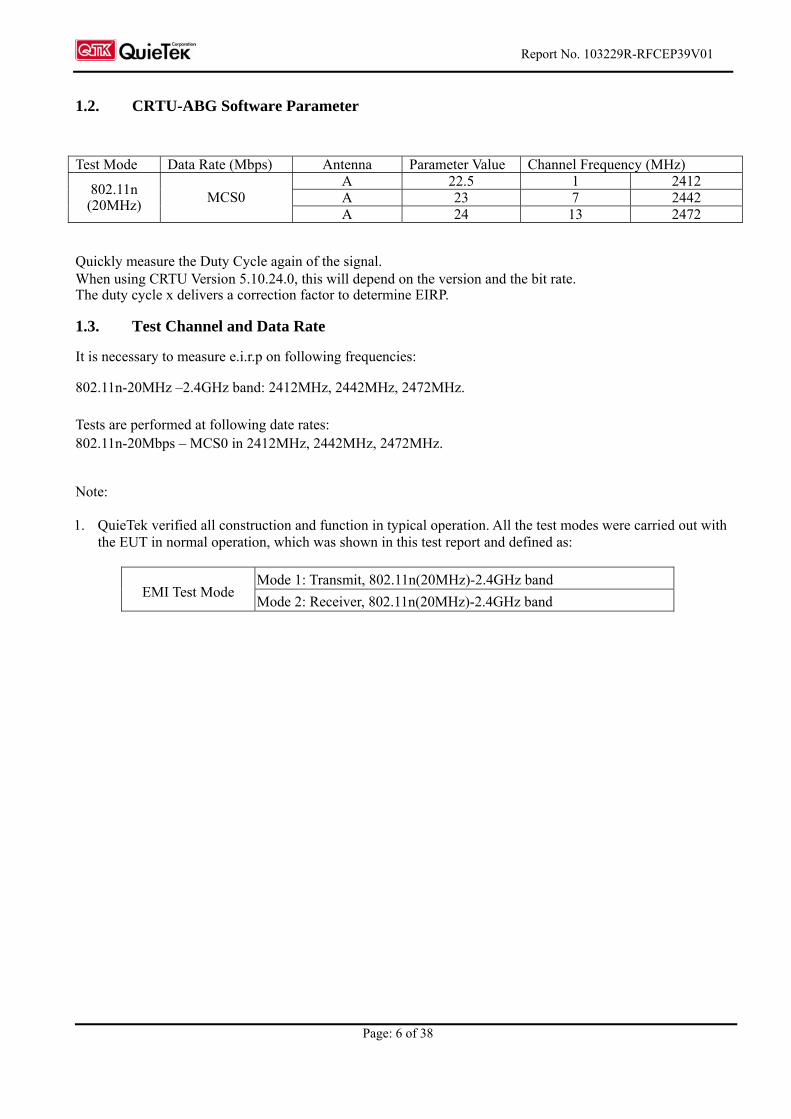
1.2. CRTU-ABG Software Parameter
Test Mode Data Rate (Mbps) Antenna Parameter Value Channel Frequency (MHz)
A 22.5 1 2412 A 23 7 2442
802.11n (20MHz) MCS0
A 24 13 2472
Quickly measure the Duty Cycle again of the signal. When using CRTU Version 5.10.24.0, this will depend on the version and the bit rate. The duty cycle x delivers a correction factor to determine EIRP.
1.3. Test Channel and Data Rate
It is necessary to measure e.i.r.p on following frequencies: 802.11n-20MHz –2.4GHz band: 2412MHz, 2442MHz, 2472MHz. Tests are performed at following date rates: 802.11n-20Mbps – MCS0 in 2412MHz, 2442MHz, 2472MHz. Note: 1. QuieTek verified all construction and function in typical operation. All the test modes were carried out with
the EUT in normal operation, which was shown in this test report and defined as:
Mode 1: Transmit, 802.11n(20MHz)-2.4GHz band EMI Test Mode
Mode 2: Receiver, 802.11n(20MHz)-2.4GHz band
Report No. 103229R-RFCEP39V01
Page: 7 of 38
1.4. Tested System Details
The types for all equipment, plus descriptions of all cables used in the tested system (including inserted cards) are:
Product Manufacturer Model No. Serial No. FCC ID Power Cord
N/A
Signal Cable Type Signal cable Description
N/A
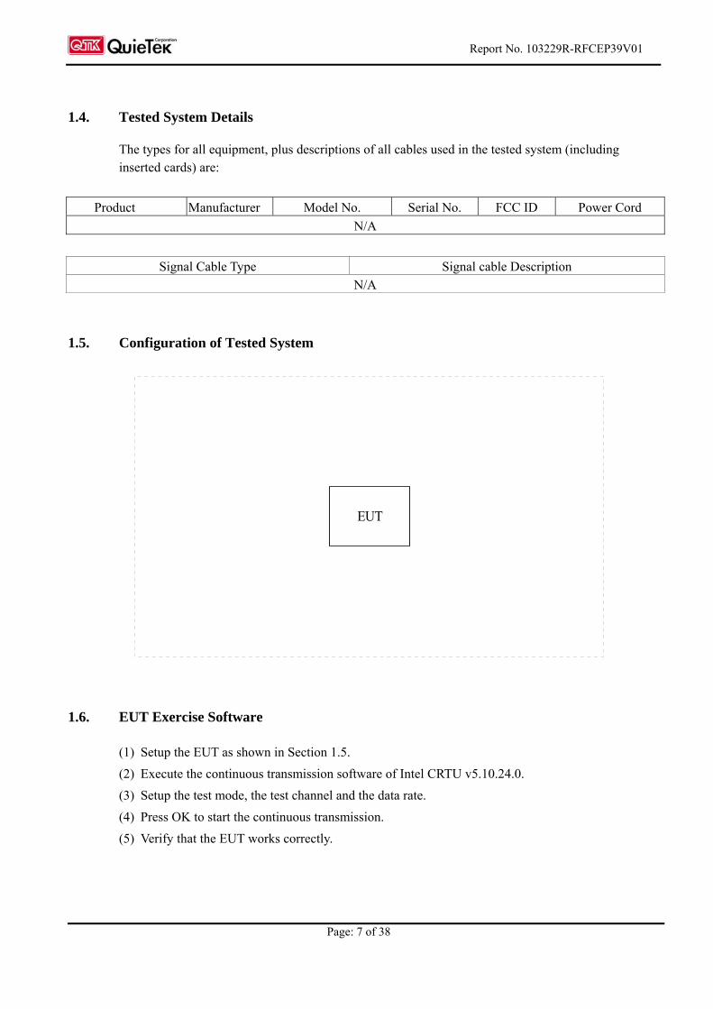
1.5. Configuration of Tested System
1.6. EUT Exercise Software
(1) Setup the EUT as shown in Section 1.5.
(2) Execute the continuous transmission software of Intel CRTU v5.10.24.0.
(3) Setup the test mode, the test channel and the data rate.
(4) Press OK to start the continuous transmission.
(5) Verify that the EUT works correctly.
EUT
Report No. 103229R-RFCEP39V01
Page: 8 of 38
1.7. Test Facility
Ambient conditions in the laboratory:
Items Test Item Required (IEC 68-1) Actual
Temperature (C) 15-35 22-27
Humidity (%RH)
ETSI EN 300 328
20-75 50-65
Site Description: File on Federal Communications Commission FCC Engineering Laboratory 7435 Oakland Mills Road Columbia, MD 21046
Registration Number: 92195
Accreditation on NVLAP NVLAP Lab Code: 200533-0 Site Name: Quietek Corporation Site Address: No. 5-22, Ruei-Shu Valley, Ruei-Ping Tsuen, Lin-Kou Shiang, Taipei, Taiwan, R.O.C. TEL: 886-2-8601-3788 / FAX: 886-2-8601-3789 E-Mail: [email protected]
Report No. 103229R-RFCEP39V01
Page: 9 of 38
2. Equivalent Isotropic Radiated Power
2.1. Test Equipment
Equipment Manufacturer Model No Serial No. Last Cal.
Power Meter Anritsu ML2495A 6K00003357 May, 2010
Power Sensor Anritsu MA2411B 0738448 Jun, 2010
Note: All equipments upon which need to be calibrated are with calibration period of 1 year.
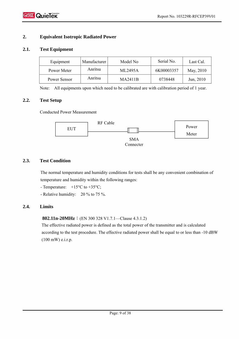
2.2. Test Setup
Conducted Power Measurement
2.3. Test Condition
The normal temperature and humidity conditions for tests shall be any convenient combination of
temperature and humidity within the following ranges:
- Temperature: +15°C to +35°C;
- Relative humidity: 20 % to 75 %.
2.4. Limits
802.11n-20MHz:(EN 300 328 V1.7.1—Clause 4.3.1.2) The effective radiated power is defined as the total power of the transmitter and is calculated
according to the test procedure. The effective radiated power shall be equal to or less than -10 dBW
(100 mW) e.i.r.p.
SMA Connecter
EUT Power
Meter
RF Cable
Report No. 103229R-RFCEP39V01
Page: 10 of 38
2.5. Test Procedure
The measurement is performed using normal operation of the equipment with test modulation applied.
The test procedure is as follows:
step 1:‧
- Using a suitable means, the output of the transmitter shall be coupled to a matched diode detector;
- The output of the diode detector shall be connected to the vertical channel of an oscilloscope.
- The combination of the diode detector and the oscilloscope shall be capable of faithfully
reproducing the envelope peaks and the duty cycle of the transmitter output signal.
- The observed duty cycle of the transmitter (Tx on/(Tx on +Tx off)) shall be noted as x, (0 < x < 1)
and recorded. For the purpose of testing, the equipment shall be operated with a duty cycle that is
equal to or more than 0,1.
step 2:‧
- The average output power of the transmitter shall be determined using a wideband, calibrated RF
power meter with a matched thermocouple detector or an equivalent thereof and, where applicable,
with an integration period that exceeds the repetition period of the transmitter by a factor 5 or more.
The observed value shall be recorded as "A" (in dBm).
- The e.i.r.p. shall be calculated from the above measured power output A, the observed duty cycle x,
and the
applicable antenna assembly gain "G" in dBi, according to the formula:
P = A + G + 10 log (1/x);
P shall be recorded in the test report. (Not exceed the value specified in ETSI EN 300 328 V1.7.1 clause
4.3.1.2)
2.6. Test Specification
According to ETSI EN 300 328 V1.7.1 (2006-10) clause 5.7.2.2
2.7. Uncertainty
± 1.27dB
2.8. Test Result
The emission from the EUT was below the specified limits. The worst-case emissions are shown in
section 2.9. The acceptance criterion was met and the EUT passed the test.
Report No. 103229R-RFCEP39V01
Page: 11 of 38
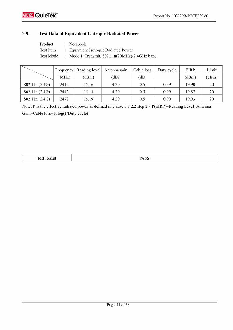
2.9. Test Data of Equivalent Isotropic Radiated Power
Product : Notebook Test Item : Equivalent Isotropic Radiated Power Test Mode : Mode 1: Transmit, 802.11n(20MHz)-2.4GHz band
Frequency Reading level Antenna gain Cable loss Duty cycle EIRP Limit
(MHz) (dBm) (dBi) (dB) (dBm) (dBm)
802.11n (2.4G) 2412 15.16 4.20 0.5 0.99 19.90 20
802.11n (2.4G) 2442 15.13 4.20 0.5 0.99 19.87 20
802.11n (2.4G) 2472 15.19 4.20 0.5 0.99 19.93 20
Note: P is the effective radiated power as defined in clause 5.7.2.2 step 2,P(EIRP)=Reading Level+Antenna
Gain+Cable loss+10log(1/Duty cycle)
Test Result PASS
Report No. 103229R-RFCEP39V01
Page: 12 of 38
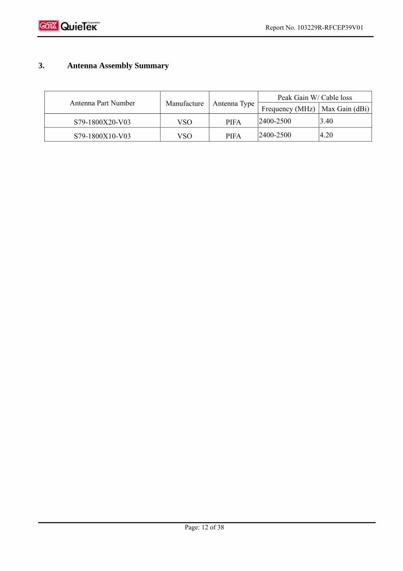
3. Antenna Assembly Summary
Peak Gain W/ Cable loss Antenna Part Number Manufacture Antenna Type
Frequency (MHz) Max Gain (dBi)
S79-1800X20-V03 VSO PIFA 2400-2500 3.40
S79-1800X10-V03 VSO PIFA 2400-2500 4.20
Report No. 103229R-RFCEP39V01
Page: 13 of 38
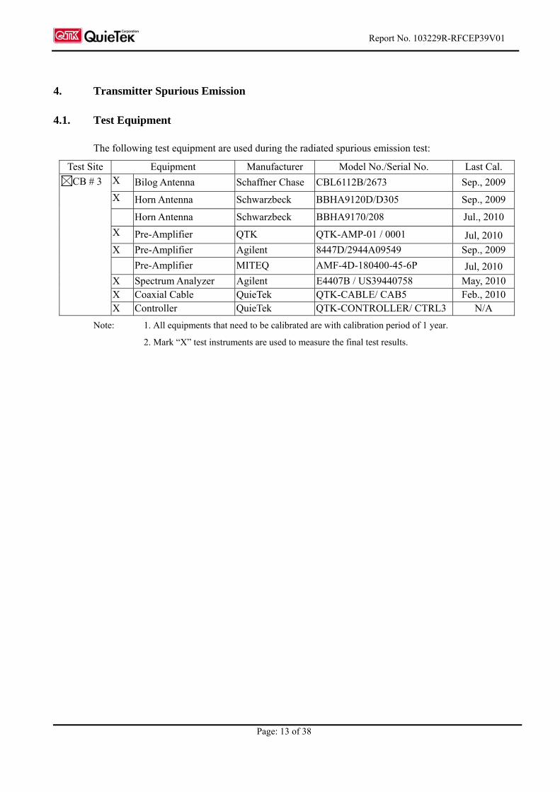
4. Transmitter Spurious Emission
4.1. Test Equipment
The following test equipment are used during the radiated spurious emission test:
Test Site Equipment Manufacturer Model No./Serial No. Last Cal. X Bilog Antenna Schaffner Chase CBL6112B/2673 Sep., 2009
X Horn Antenna Schwarzbeck BBHA9120D/D305 Sep., 2009
Horn Antenna Schwarzbeck BBHA9170/208 Jul., 2010
X Pre-Amplifier QTK QTK-AMP-01 / 0001 Jul, 2010
X Pre-Amplifier Agilent 8447D/2944A09549 Sep., 2009 Pre-Amplifier MITEQ AMF-4D-180400-45-6P Jul, 2010
X Spectrum Analyzer Agilent E4407B / US39440758 May, 2010 X Coaxial Cable QuieTek QTK-CABLE/ CAB5 Feb., 2010
CB # 3
X Controller QuieTek QTK-CONTROLLER/ CTRL3 N/A
Note: 1. All equipments that need to be calibrated are with calibration period of 1 year.
2. Mark “X” test instruments are used to measure the final test results.
Report No. 103229R-RFCEP39V01
Page: 14 of 38
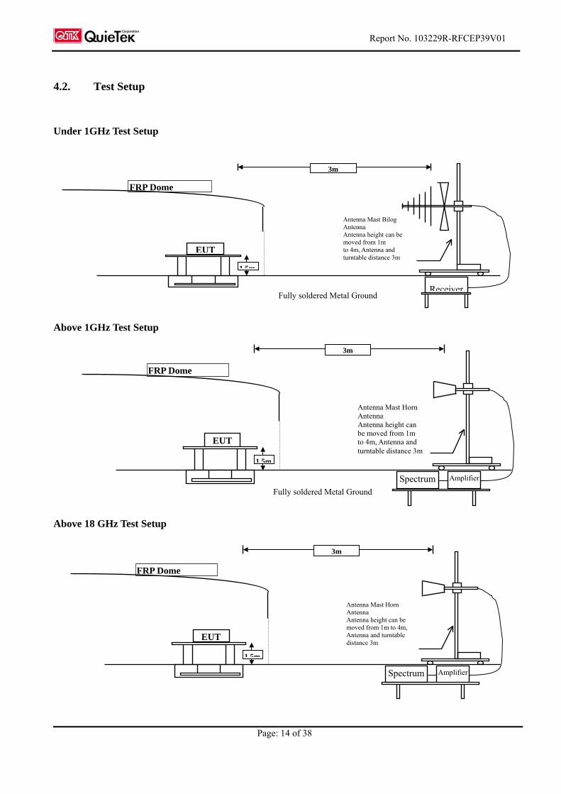
4.2. Test Setup
Under 1GHz Test Setup
Fully soldered Metal Ground
Above 1GHz Test Setup
Fully soldered Metal Ground
Above 18 GHz Test Setup
EUT
FRP Dome
Antenna Mast Horn Antenna Antenna height can be moved from 1m to 4m, Antenna and turntable distance 3m
3m
1 5m
Spectrum Amplifier
Receiver
EUT
FRP Dome
Antenna Mast Bilog Antenna Antenna height can be moved from 1m to 4m, Antenna and turntable distance 3m
3m
1 5m
EUT
FRP Dome
Antenna Mast Horn Antenna Antenna height can be moved from 1m to 4m, Antenna and turntable distance 3m
3m
1.5m
Spectrum Amplifier
Report No. 103229R-RFCEP39V01
Page: 15 of 38
4.3. Test Condition
The normal temperature and humidity conditions for tests shall be any convenient combination of
temperature and humidity within the following ranges:
- Temperature: +15°C to +35°C;
- Relative humidity: 20 % to 75 %.
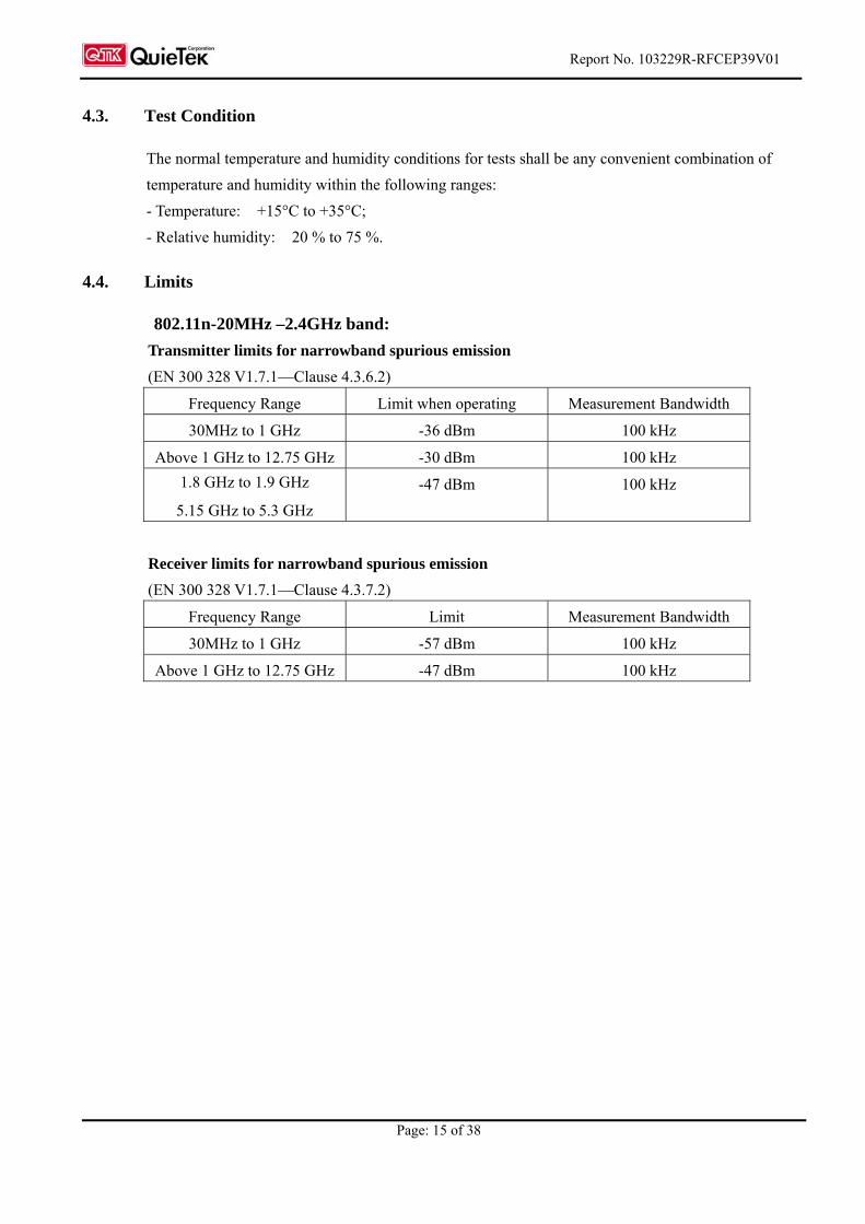
4.4. Limits
802.11n-20MHz –2.4GHz band:
Transmitter limits for narrowband spurious emission
(EN 300 328 V1.7.1—Clause 4.3.6.2)
Frequency Range Limit when operating Measurement Bandwidth
30MHz to 1 GHz -36 dBm 100 kHz
Above 1 GHz to 12.75 GHz -30 dBm 100 kHz
1.8 GHz to 1.9 GHz
5.15 GHz to 5.3 GHz
-47 dBm 100 kHz
Receiver limits for narrowband spurious emission
(EN 300 328 V1.7.1—Clause 4.3.7.2)
Frequency Range Limit Measurement Bandwidth
30MHz to 1 GHz -57 dBm 100 kHz
Above 1 GHz to 12.75 GHz -47 dBm 100 kHz
Report No. 103229R-RFCEP39V01
Page: 16 of 38
4.5. Test Procedure
The EUT and its simulators are placed on a turn table which is 1.5 meters above ground. The turn table
can rotate 360 degrees to determine the position of the maximum emission level. The EUT was
positioned such that the distance from antenna to the EUT was 3 meters.The antenna can move up and
down between 1 meter and 4 meters to find out the maximum emission level.
Broadband antenna (calibrated bi-log and horn antenna) are used as a receiving antenna.
Both horizontal and vertical polarization of the antenna are set on measurement. And a high frequency
preamlifier were used increase the sensitivity of the measuring. In order to find the maximum emission,
all of the interface cables must be manipulated according to ETSI EN 300 328:V1.7.1 (2006-10) on
radiated measurement.
The additional notch filter below 1GHz was used to measure the level of harmonics radiated emission
during field strength of harmonics measurement. The bandwidth below 1GHz setting on the field
strength meter is 120 kHz, and 100 kHz bandwidth is adopted above 1GHz. The frequency range from
30MHz to 12.75GHz is checked.
4.6. Test Specification
According to ETSI EN 300 328:V1.7.1 (2006-10) clause 5.7.5
4.7. Uncertainty
± 3.9 dB above 1GHz
± 3.8 dB below 1GHz
4.8. Test Result
The emission from the EUT was below the specified limits. The worst-case emissions are shown in
section 3.9. The acceptance criterion was met and the EUT passed the test.
Report No. 103229R-RFCEP39V01
Page: 17 of 38
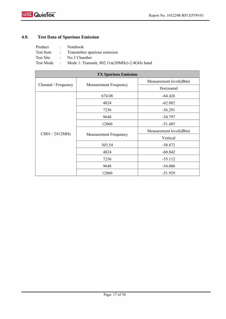
4.9. Test Data of Spurious Emission
Product : Notebook Test Item : Transmitter spurious emission Test Site : No.3 Chamber Test Mode : Mode 1: Transmit, 802.11n(20MHz)-2.4GHz band
TX Spurious Emission
Measurement level(dBm) Chennal / Frequency Measurement Frequency
Horizontal
674.08 -64.426
4824 -62.882
7236 -56.291
9648 -54.797
12060 -51.485
Measurement level(dBm) Measurement Frequency
Vertical
303.54 -58.872
4824 -60.842
7236 -55.112
9648 -54.006
CH01 / 2412MHz
12060 -51.929
Report No. 103229R-RFCEP39V01
Page: 18 of 38
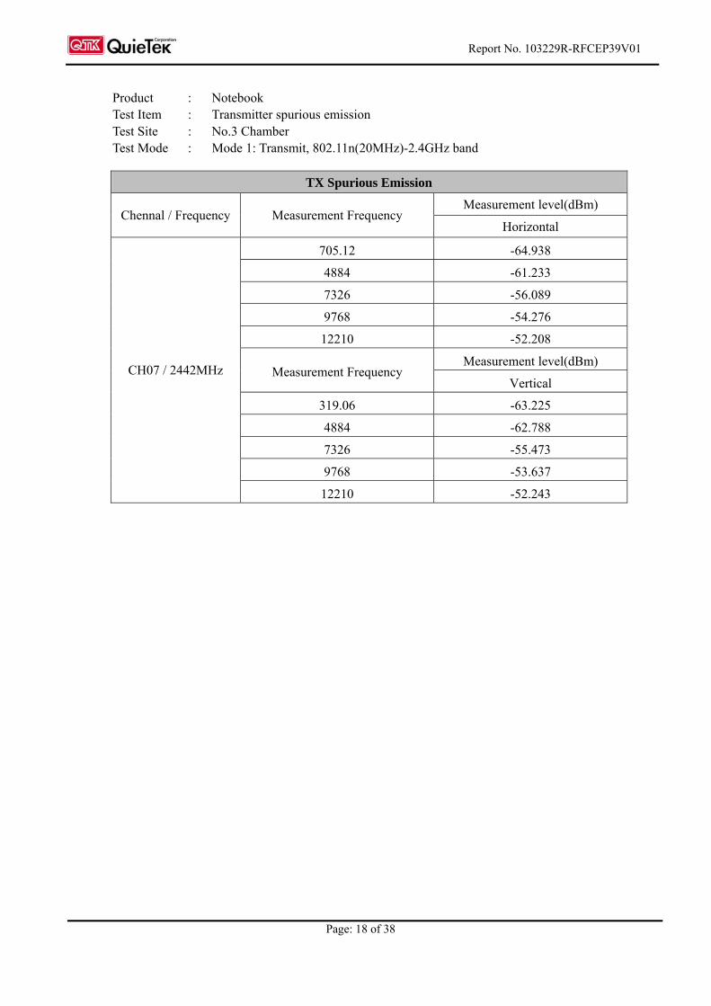
Product : Notebook Test Item : Transmitter spurious emission Test Site : No.3 Chamber Test Mode : Mode 1: Transmit, 802.11n(20MHz)-2.4GHz band
TX Spurious Emission
Measurement level(dBm) Chennal / Frequency Measurement Frequency
Horizontal
705.12 -64.938
4884 -61.233
7326 -56.089
9768 -54.276
12210 -52.208
Measurement level(dBm) Measurement Frequency
Vertical
319.06 -63.225
4884 -62.788
7326 -55.473
9768 -53.637
CH07 / 2442MHz
12210 -52.243
Report No. 103229R-RFCEP39V01
Page: 19 of 38
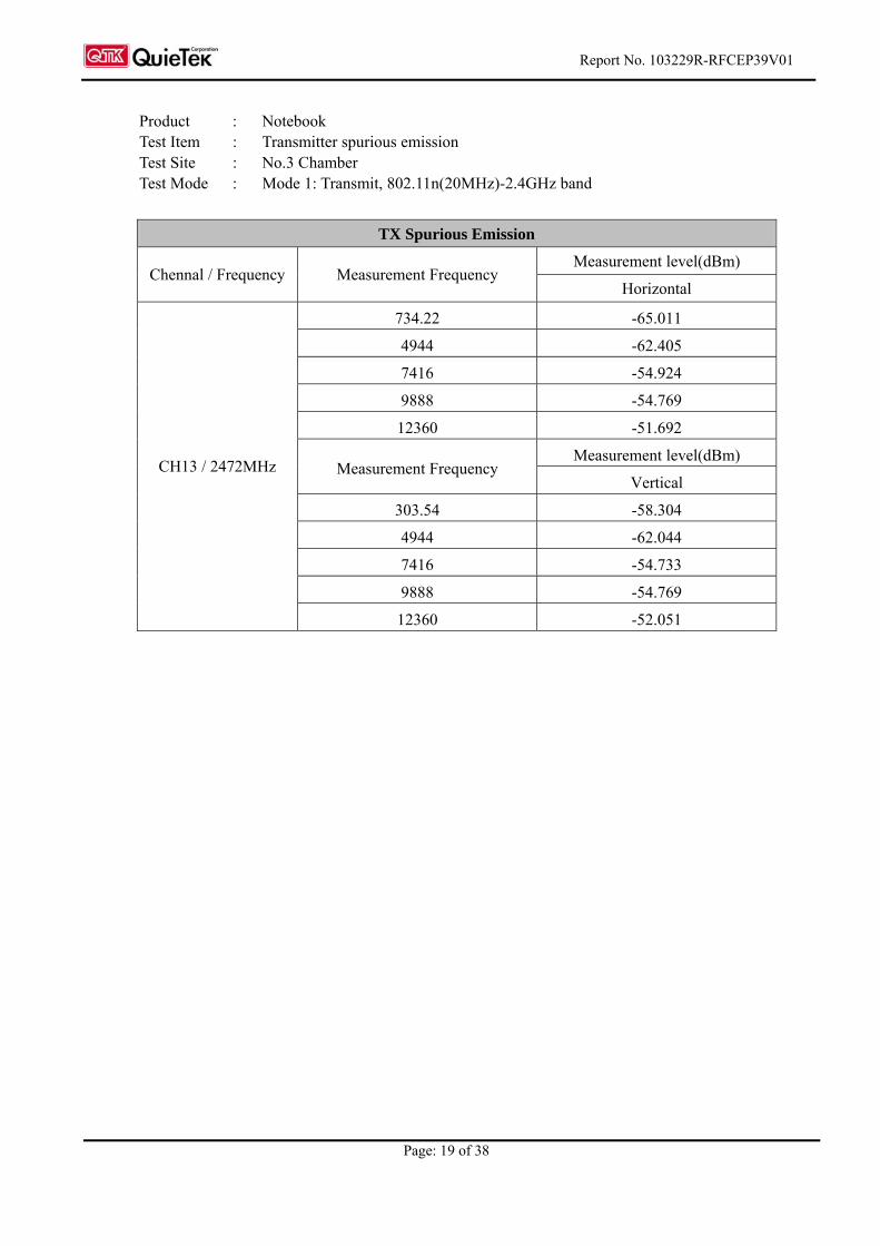
Product : Notebook Test Item : Transmitter spurious emission Test Site : No.3 Chamber Test Mode : Mode 1: Transmit, 802.11n(20MHz)-2.4GHz band
TX Spurious Emission
Measurement level(dBm) Chennal / Frequency Measurement Frequency
Horizontal
734.22 -65.011
4944 -62.405
7416 -54.924
9888 -54.769
12360 -51.692
Measurement level(dBm) Measurement Frequency
Vertical
303.54 -58.304
4944 -62.044
7416 -54.733
9888 -54.769
CH13 / 2472MHz
12360 -52.051

Report No. 103229R-RFCEP39V01
Page: 20 of 38
5. Receiver Spurious Emission
5.1. Test Equipment
The following test equipment are used during the radiated spurious emission test:
Test Site Equipment Manufacturer Model No./Serial No. Last Cal. X Bilog Antenna Schaffner Chase CBL6112B/2673 Sep., 2009
X Horn Antenna Schwarzbeck BBHA9120D/D305 Sep., 2009
Horn Antenna Schwarzbeck BBHA9170/208 Jul., 2010
X Pre-Amplifier QTK QTK-AMP-01 / 0001 July, 2010
X Pre-Amplifier Agilent 8447D/2944A09549 Sep., 2009 Pre-Amplifier MITEQ AMF-4D-180400-45-6P July, 2010
X Spectrum Analyzer Agilent E4407B / US39440758 May, 2010 X Coaxial Cable QuieTek QTK-CABLE/ CAB5 Feb., 2010
CB # 3
X Controller QuieTek QTK-CONTROLLER/ CTRL3 N/A
Note: 1. All equipments that need to be calibrated are with calibration period of 1 year.
2. Mark “X” test instruments are used to measure the final test results.
Report No. 103229R-RFCEP39V01
Page: 21 of 38
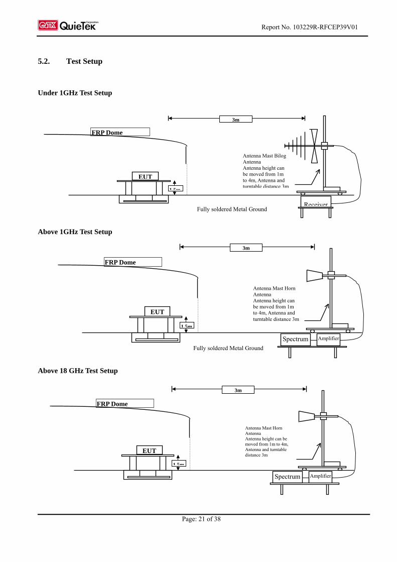
5.2. Test Setup
Under 1GHz Test Setup
Fully soldered Metal Ground
Above 1GHz Test Setup
Fully soldered Metal Ground
Above 18 GHz Test Setup
EUT
FRP Dome
Antenna Mast Horn Antenna Antenna height can be moved from 1m to 4m, Antenna and turntable distance 3m
3m
1 5m
Spectrum Amplifier
Receiver
EUT
FRP Dome
Antenna Mast Bilog Antenna Antenna height can be moved from 1m to 4m, Antenna and turntable distance 3m
3m
1 5m
EUT
FRP Dome
Antenna Mast Horn Antenna Antenna height can be moved from 1m to 4m, Antenna and turntable distance 3m
3m
1.5m
Spectrum Amplifier
Report No: 103229R-RFCEP39V01
Page: 22 of 38
5.3. Test Condition
The normal temperature and humidity conditions for tests shall be any convenient combination of
temperature and humidity within the following ranges:
- Temperature: +15°C to +35°C;
- Relative humidity: 20 % to 75 %.
5.4. Limits
802.11n-20MHz –2.4GHz band:
Receiver limits for narrowband spurious emission
(EN 300 328 V1.7.1—Clause 4. 3.7.2)
Frequency Range Limit Measurement Bandwidth
30MHz to 1 GHz -57 dBm 100 kHz
Above 1 GHz to 12.75 GHz -47 dBm 100 kHz
5.5. Test Procedure
The EUT and its simulators are placed on a turn table which is 1.5 meters above ground. The turn table
can rotate 360 degrees to determine the position of the maximum emission level. The EUT was
positioned such that the distance from antenna to the EUT was 3 meters.The antenna can move up and
down between 1 meter and 4 meters to find out the maximum emission level.
Broadband antenna (calibrated bi-log and horn antenna) are used as a receiving antenna.
Both horizontal and vertical polarization of the antenna are set on measurement. And a high frequency
preamlifier were used increase the sensitivity of the measuring. In order to find the maximum emission,
all of the interface cables must be manipulated according to ETSI EN 300 328:V1.7.1 (2006-10) on
radiated measurement.
The additional notch filter below 1GHz was used to measure the level of harmonics radiated emission
during field strength of harmonics measurement. The bandwidth below 1GHz setting on the field
strength meter is 100 kHz, and 100 kHz bandwidth is adopted above 1GHz. The frequency range from
30MHz to 12.75GHz is checked.
Report No: 103229R-RFCEP39V01
Page: 23 of 38
5.6. Test Specification
According to ETSI EN 300 328:V1.7.1 (2006-10) clause 5.7.5
5.7. Uncertainty
± 3.9 dB above 1GHz
± 3.8 dB below 1GHz
5.8. Test Result
The emission from the EUT was below the specified limits. The worst-case emissions are shown in
section 3.9. The acceptance criterion was met and the EUT passed the test.
Report No: 103229R-RFCEP39V01
Page: 24 of 38
5.9. Test Data of Spurious Emission
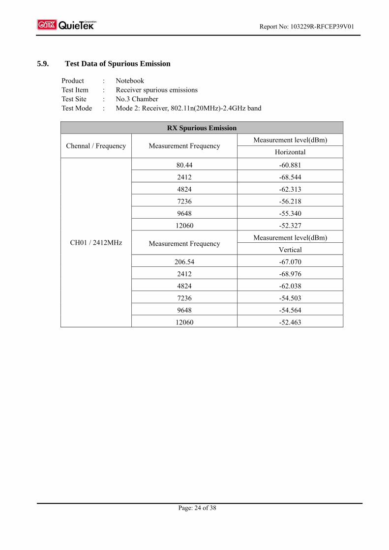
Product : Notebook Test Item : Receiver spurious emissions Test Site : No.3 Chamber Test Mode : Mode 2: Receiver, 802.11n(20MHz)-2.4GHz band
RX Spurious Emission
Measurement level(dBm) Chennal / Frequency Measurement Frequency
Horizontal
80.44 -60.881
2412 -68.544
4824 -62.313
7236 -56.218
9648 -55.340
12060 -52.327
Measurement level(dBm) Measurement Frequency
Vertical
206.54 -67.070
2412 -68.976
4824 -62.038
7236 -54.503
9648 -54.564
CH01 / 2412MHz
12060 -52.463
Report No: 103229R-RFCEP39V01
Page: 25 of 38
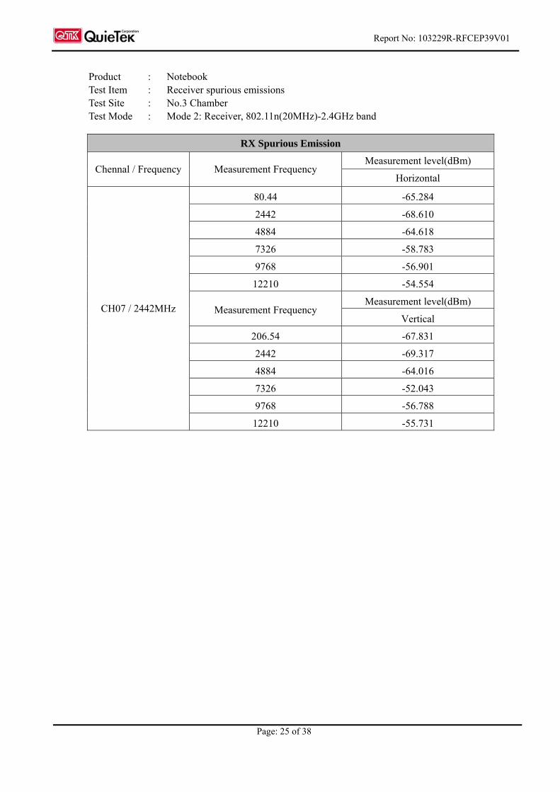
Product : Notebook Test Item : Receiver spurious emissions Test Site : No.3 Chamber Test Mode : Mode 2: Receiver, 802.11n(20MHz)-2.4GHz band
RX Spurious Emission
Measurement level(dBm) Chennal / Frequency Measurement Frequency
Horizontal
80.44 -65.284
2442 -68.610
4884 -64.618
7326 -58.783
9768 -56.901
12210 -54.554
Measurement level(dBm) Measurement Frequency
Vertical
206.54 -67.831
2442 -69.317
4884 -64.016
7326 -52.043
9768 -56.788
CH07 / 2442MHz
12210 -55.731
Report No: 103229R-RFCEP39V01
Page: 26 of 38
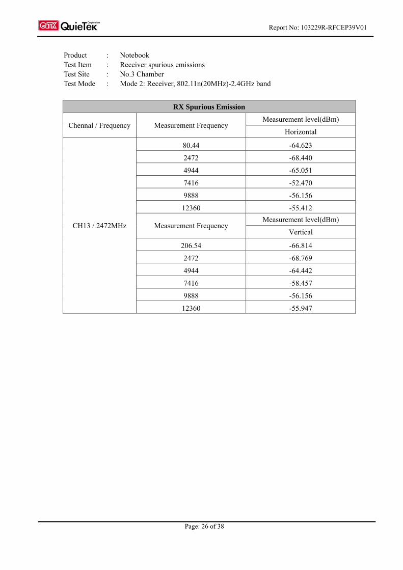
Product : Notebook Test Item : Receiver spurious emissions Test Site : No.3 Chamber Test Mode : Mode 2: Receiver, 802.11n(20MHz)-2.4GHz band
RX Spurious Emission
Measurement level(dBm) Chennal / Frequency Measurement Frequency
Horizontal
80.44 -64.623
2472 -68.440
4944 -65.051
7416 -52.470
9888 -56.156
12360 -55.412
Measurement level(dBm) Measurement Frequency
Vertical
206.54 -66.814
2472 -68.769
4944 -64.442
7416 -58.457
9888 -56.156
CH13 / 2472MHz
12360 -55.947
Report No: 103229R-RFCEP39V01
Page: 27 of 38
6. Measurement Uncertainty Values
The maximum values of the absolute measurement uncertainties of the measurements defined in the
present document shall not exceed the values given below:
802.11n-20MHz-2.4G band:
Parameter Uncertainty
Total RF power, conducted 1.5 dB
All emissions, radiated 6 dB
Temperature 1oC
Humidity 5 %
DC and low frequency voltages 3 %
For the measurement methods according to the present document these uncertainty figures are valid to
a confidence level of 95 % calculated according to the methods described in ETR 028 [5], on
guidelines for estimating uncertainties in measuring methods.
Report No: 103229R-RFCEP39V01
Page: 28 of 38
7. EMC Reduction Method During Compliance Testing
No modification was made during testing.
Report No: 103229R-RFCEP39V01
Page: 29 of 38
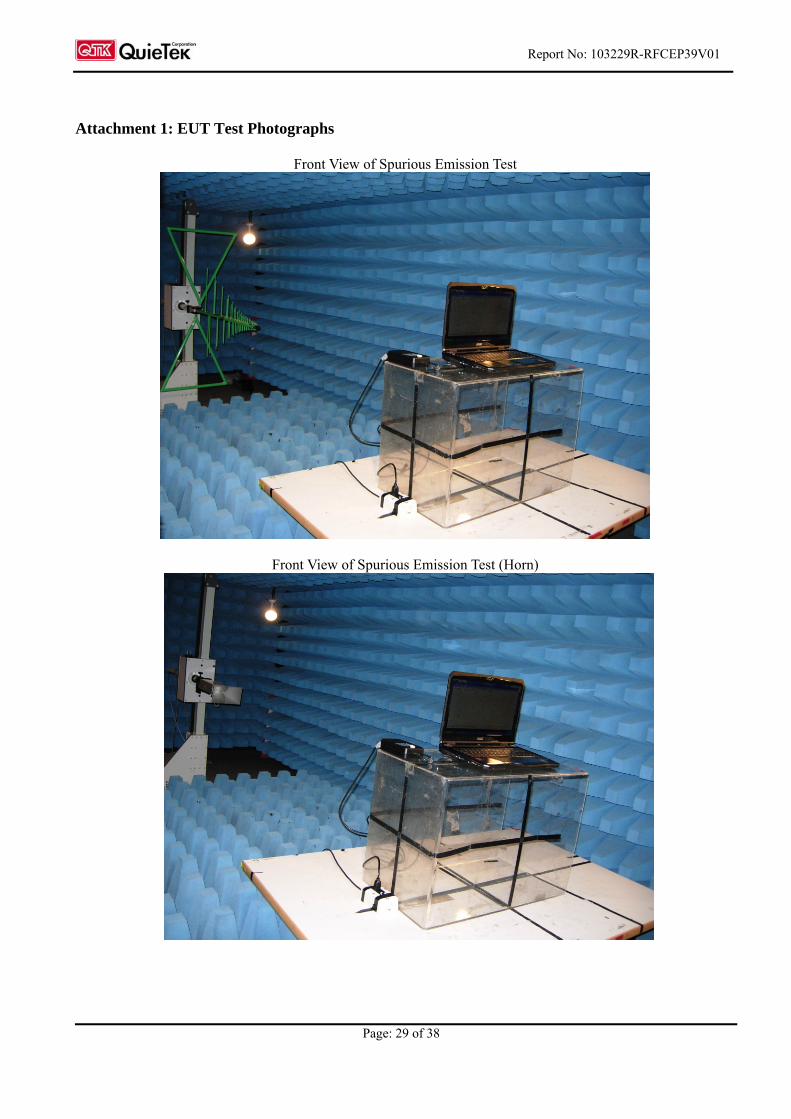
Attachment 1: EUT Test Photographs
Front View of Spurious Emission Test
Front View of Spurious Emission Test (Horn)
Report No: 103229R-RFCEP39V01
Page: 30 of 38
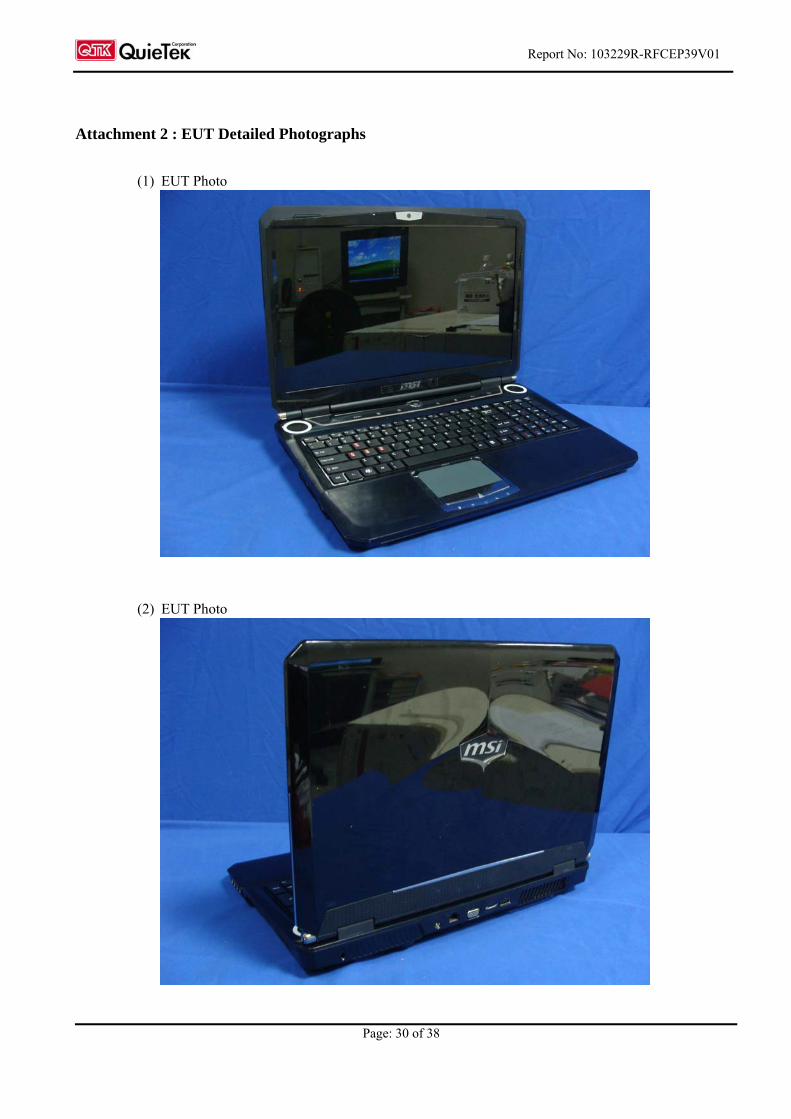
Attachment 2 : EUT Detailed Photographs
(1) EUT Photo
(2) EUT Photo
Report No: 103229R-RFCEP39V01
Page: 31 of 38
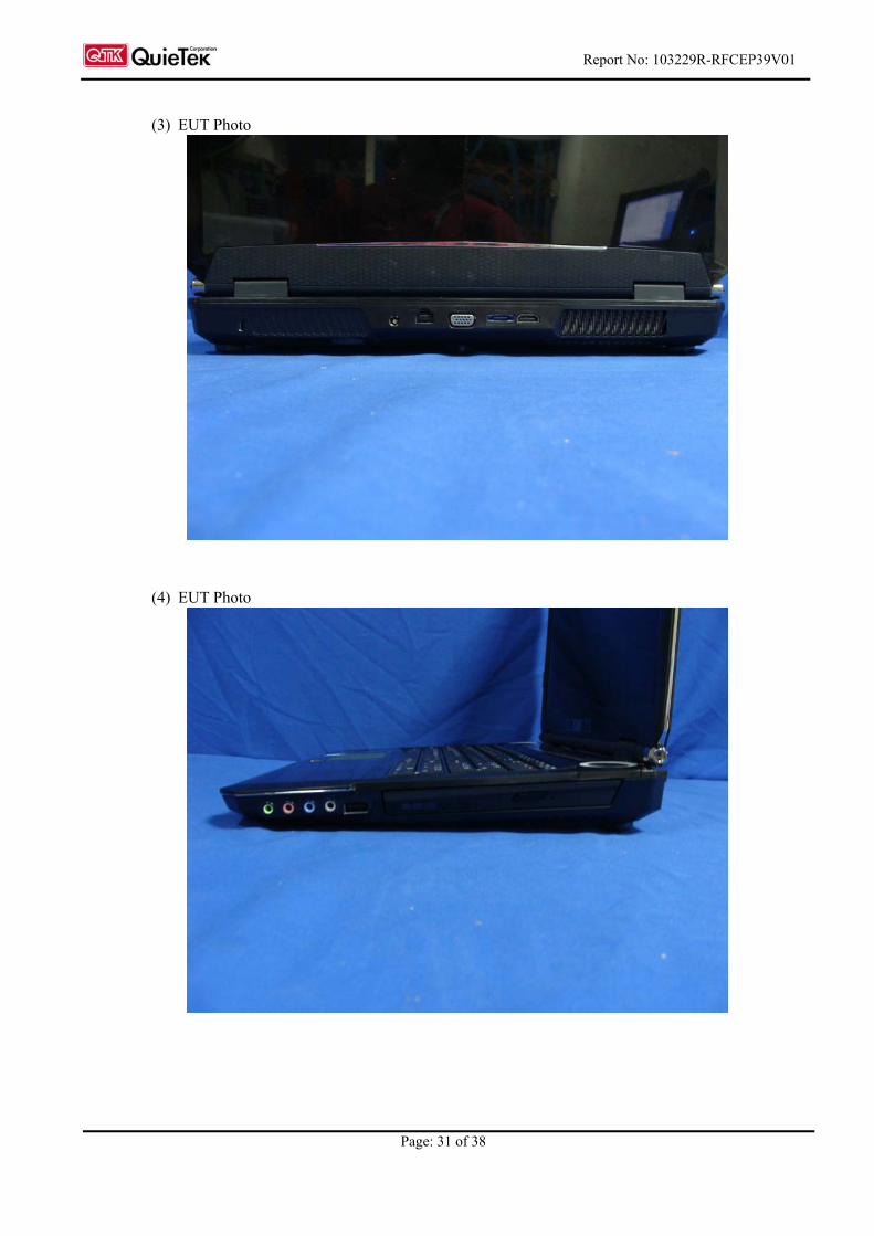
(3) EUT Photo
(4) EUT Photo
Report No: 103229R-RFCEP39V01
Page: 32 of 38
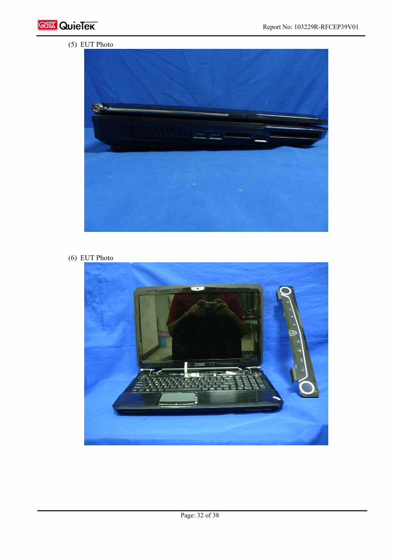
(5) EUT Photo
(6) EUT Photo
Report No: 103229R-RFCEP39V01
Page: 33 of 38
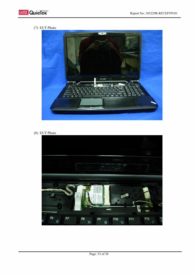
(7) EUT Photo
(8) EUT Photo
Report No: 103229R-RFCEP39V01
Page: 34 of 38
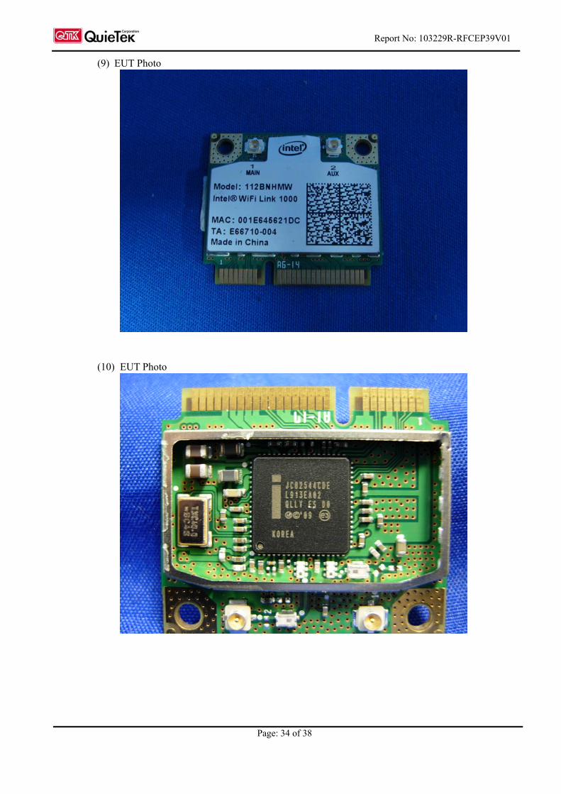
(9) EUT Photo
(10) EUT Photo
Report No: 103229R-RFCEP39V01
Page: 35 of 38
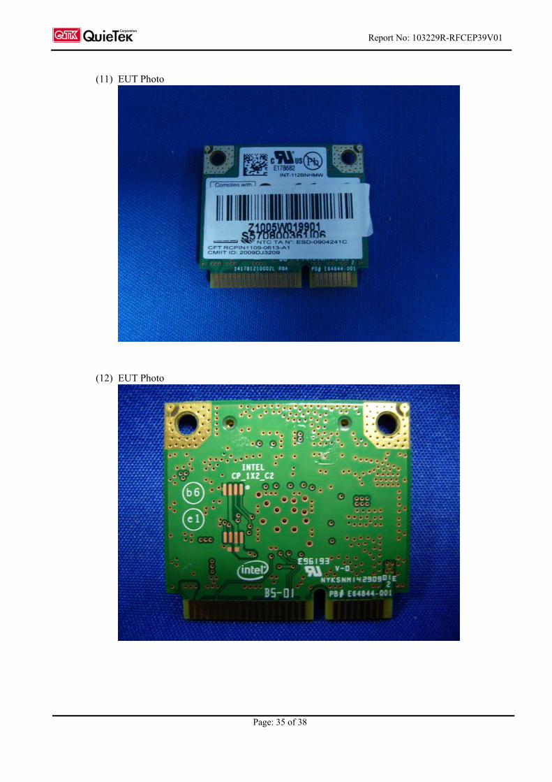
(11) EUT Photo
(12) EUT Photo
Report No: 103229R-RFCEP39V01
Page: 36 of 38
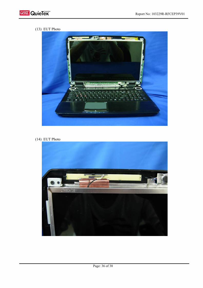
(13) EUT Photo
(14) EUT Photo
Report No: 103229R-RFCEP39V01
Page: 37 of 38
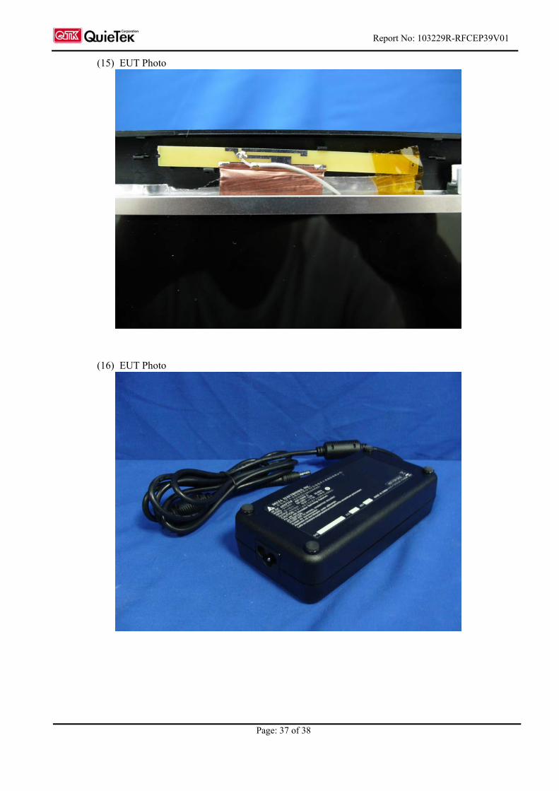
(15) EUT Photo
(16) EUT Photo
Report No: 103229R-RFCEP39V01
Page: 38 of 38
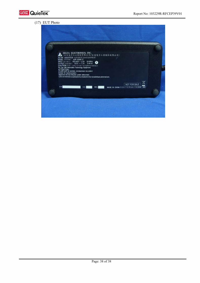
(17) EUT Photo


![[PPT]Origin Myths and Early Colonial Literatureuhs.twpunionschools.org/subsites/aselby/documents/EN301... · Web viewOrigin Myths The first people… Native Americans immigrated over](https://img.pdfslide.net/doc/110x75/5ae9e03f7f8b9a66258b49fc/pptorigin-myths-and-early-colonial-vieworigin-myths-the-first-people-native.jpg)