Embed Size (px)
Citation preview

Grégoire LEONARD
Reactors for CO2 utilization
PEPS group
Products, Environment and Processes
January 2016
2
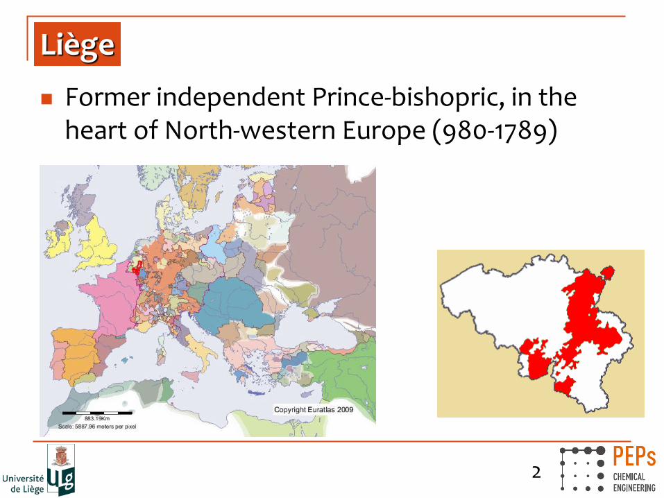
Liège
Former independent Prince-bishopric, in the heart of North-western Europe (980-1789)

3
Liège
Now 3rd urban area in Belgium, ~750 000 inh.
4
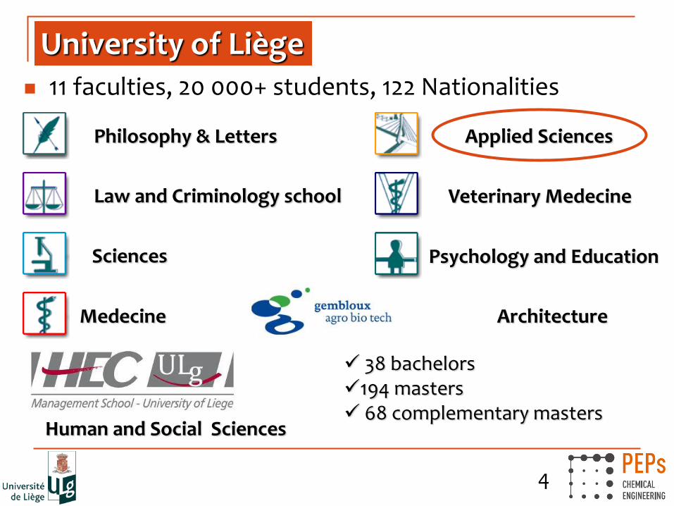
University of Liège 11 faculties, 20 000+ students, 122 Nationalities
Philosophy & Letters
Law and Criminology school
Sciences
Medecine
Applied Sciences
Veterinary Medecine
Psychology and Education
Human and Social Sciences
38 bachelors 194 masters 68 complementary masters
Architecture
5
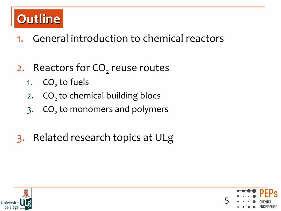
Outline
1. General introduction to chemical reactors
2. Reactors for CO2 reuse routes
1. CO2 to fuels
2. CO2 to chemical building blocs
3. CO2 to monomers and polymers
3. Related research topics at ULg

6
1. General introduction
Industrial/chemical process:
A process is a series of matter and energy transformation steps
These steps are known as unit operations (UO)
The reactor is the step where chemical reaction(s) are implied

7
1. General introduction
Example: CO2 capture from flue gas
© G Leonard, 2015

8
1. General introduction
Example: CO2 capture from flue gas
© G Leonard, 2015
9
1. General introduction
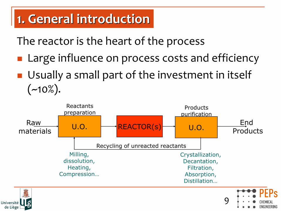
The reactor is the heart of the process
Large influence on process costs and efficiency
Usually a small part of the investment in itself (~10%).
End Products
Reactants preparation
Products purification
U.O. REACTOR(s) U.O. Raw
materials
Recycling of unreacted reactants
Milling, dissolution,
Heating, Compression…
Crystallization, Decantation,
Filtration, Absorption, Distillation…

10
1. General introduction
How to choose the right reactor?
High variety of reactions and operating conditions
Close links between physical and chemical phenomena, non-linear behaviors
Rational analysis of processes needed to identify limiting factors
No "one-size-fits-all" solution!

11
1. General introduction
Criterion Types of reactions
Phases Homogeneous (1 phase)
Heterogeneous (2, 3 or 4 phases)
Stoichiometry
Simple (1 reaction)
Complex (multiple reactions, side
reactions…)
Thermodynamics Irreversible
Equilibrium
Kinetics Limiting factors are physical
Limiting factors are chemical
Heat balance (Strongly) Endothermal (H > 0)
(Strongly) Exothermal (H < 0)
12
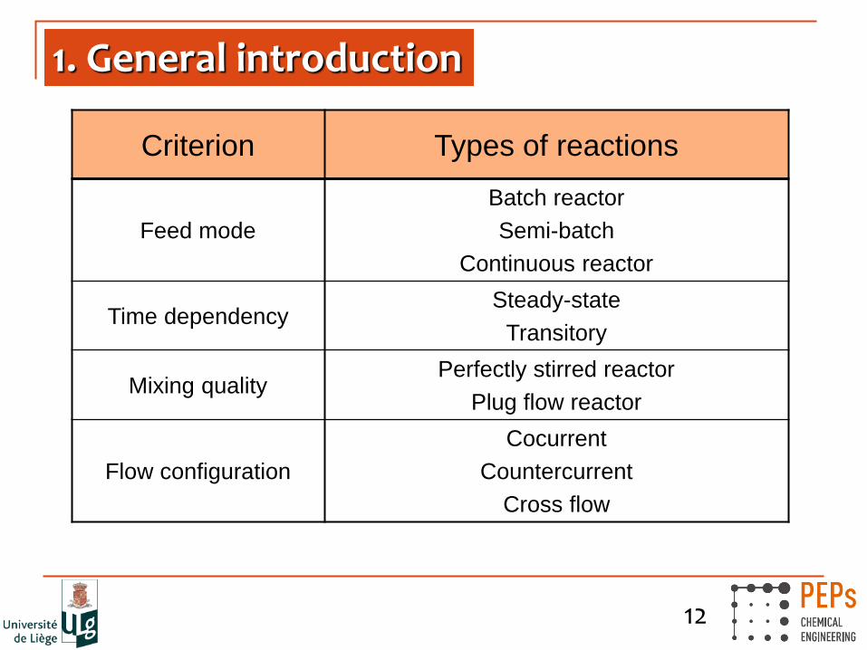
1. General introduction
Criterion Types of reactions
Feed mode
Batch reactor
Semi-batch
Continuous reactor
Time dependency Steady-state
Transitory
Mixing quality Perfectly stirred reactor
Plug flow reactor
Flow configuration
Cocurrent
Countercurrent
Cross flow
13
1. General introduction
Goal of reactor design:
Achieve the best possible coupling between
The reaction(s)
The reactor
=> optimize reaction conditions and reach optimal production and selectivity

14
1. General introduction
Main types of industrial reactors:
Homogeneous reactors:
Stirred tank reactor (liquid phase)
Tubular reactor (liquid or gas phase)
Heterogeneous reactors:
Slurry, fixed-bed, moving-bed, fluidized-bed, bubble column…
Often due to the presence of solid catalyst
Pseudo-homogeneous modelling: use of apparent kinetics, which includes heat and mass transfer limitations

15
1. General introduction
Heterogeneous reactors:
Stirred-tank slurry
Fixed-bed reactor
Fluidized-bed reactor

16
1. General introduction
Homogeneous reactors
Batch Semi-batch Continuous
- Small production volumes
- Flexible equipment
- Complex reactions
- Strongly exothermal
reactions
- Equilibrium-limited
reactions
- Larger prod. volumes
- Continuous operation

17
1. General introduction
Tubular reactors w
ww
.pse
nte
rpri
se.c
om
- Good heat management
- Reaction under vacuum or high pressure
- Continuous
- Fast reactions
Tubular reactor for naphtha cracking
ww
w.e
ssen
tial
chem
ical
indust
ry.o
rg/

18
2. CO2 re-use reactors
Chemical re-use pathways…
=> CO2 can be a useful source of carbon, it’s just that you need energy…

19
2.1 CO2 to fuels
Conventional methanol synthesis
Limiting step: thermodynamic equilibrium (25% H2 conversion)
=> High P, Low T
Gas recycle
Ind. Eng. Chem. Res., Vol. 49, No. 13, 2010

20
2.1 CO2 to fuels
Conventional methanol synthesis
=> assuming syngas availability!
3,000 t/d methanol plant at Oman Methanol Company L.L.C., TOYO Engineering
Haldor Topsoe, > 10 000 t/d

21
2.1 CO2 to fuels
Novel methanol reactor designs
Improve the heat management
Lower ΔP at high flow rates
Arab S. et al., 2014. DOI: 10.1016/j.cherd.2014.03.009 Montebelli et al., 2013. DOI: 10.1016/j.cattod.2013.02.020

22
2.1 CO2 to fuels
Novel methanol reactor designs
Remove the thermodynamic limitation
Displace the equilibrium
Conversion reaches 99.9%!
Bos and Brilman, 2014. DOI: 10.1016/j.cej.2014.10.059
23
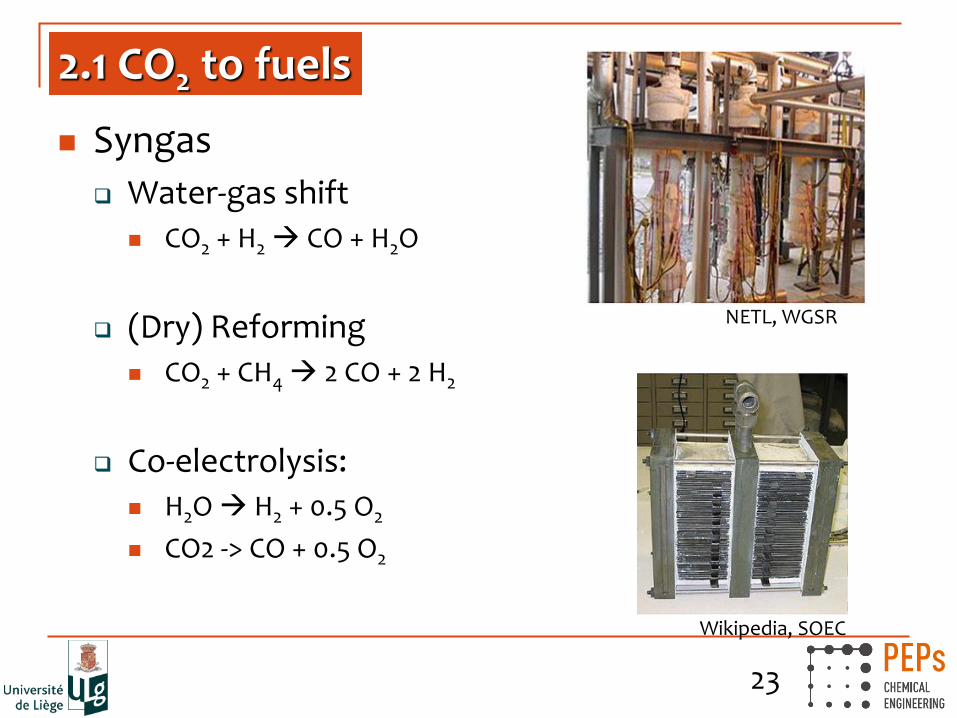
2.1 CO2 to fuels
Syngas
Water-gas shift
CO2 + H2 CO + H2O
(Dry) Reforming
CO2 + CH4 2 CO + 2 H2
Co-electrolysis:
H2O H2 + 0.5 O2
CO2 -> CO + 0.5 O2
Wikipedia, SOEC
NETL, WGSR

24
2.1 CO2 to fuels
DME (CH3OCH3)
Directly from syngas => more exothermal => slurry
From methanol => fixed bed gas reactor
Turton et al., Prentice Hall, 2012
Yagi et al., 2010. DOI: 10.2202/1542-6580.2267
25
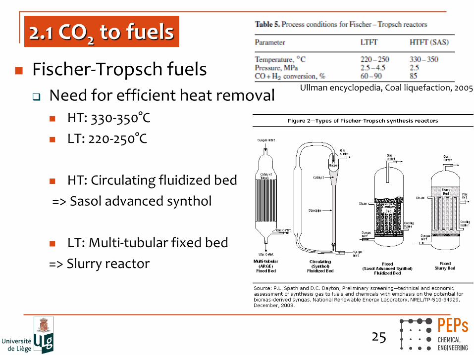
2.1 CO2 to fuels
Fischer-Tropsch fuels
Need for efficient heat removal
HT: 330-350°C
LT: 220-250°C
HT: Circulating fluidized bed
=> Sasol advanced synthol
LT: Multi-tubular fixed bed
=> Slurry reactor
Ullman encyclopedia, Coal liquefaction, 2005

26
2.2 CO2 to chemical building blocs
Formic acid
Main route: CO + H2O + methanol catalyst
Alternative: CO2 + H2
Reaction in liquid phase, need for basic conditions
Low TRL
Blair and Berman, University of Central Florida, WO 2014/089537 A1
27
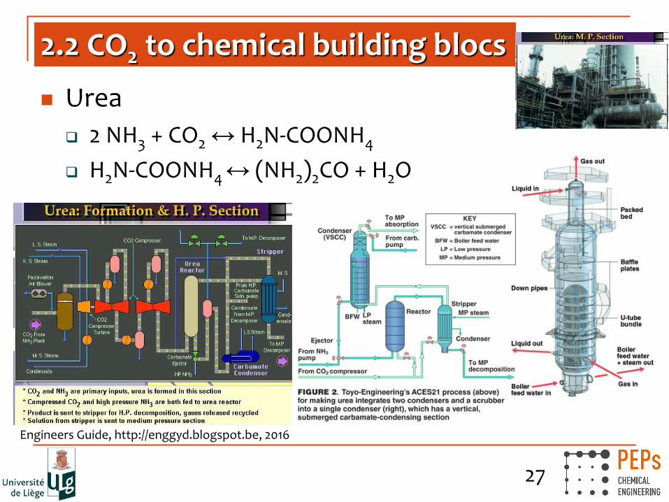
2.2 CO2 to chemical building blocs
Urea
2 NH3 + CO2 ↔ H2N-COONH4
H2N-COONH4 ↔ (NH2)2CO + H2O
Engineers Guide, http://enggyd.blogspot.be, 2016

28
2.2 CO2 to chemical building blocs
Mineralization
Formation of Ca and Mg carbonates
Recoval, 2015

29
2.3 CO2 to monomers and polymers
CO2
Gennen & al., Chemsuschem, 2015, 11, 1845-1849; Alves & al., RSC Adv., 2015, 5, 53629-53636; Alves & al., Catal. Sci. Technol., 2015, 5, 4636-4643, Poussard & al., Macromolecules, 2016, accepted
30
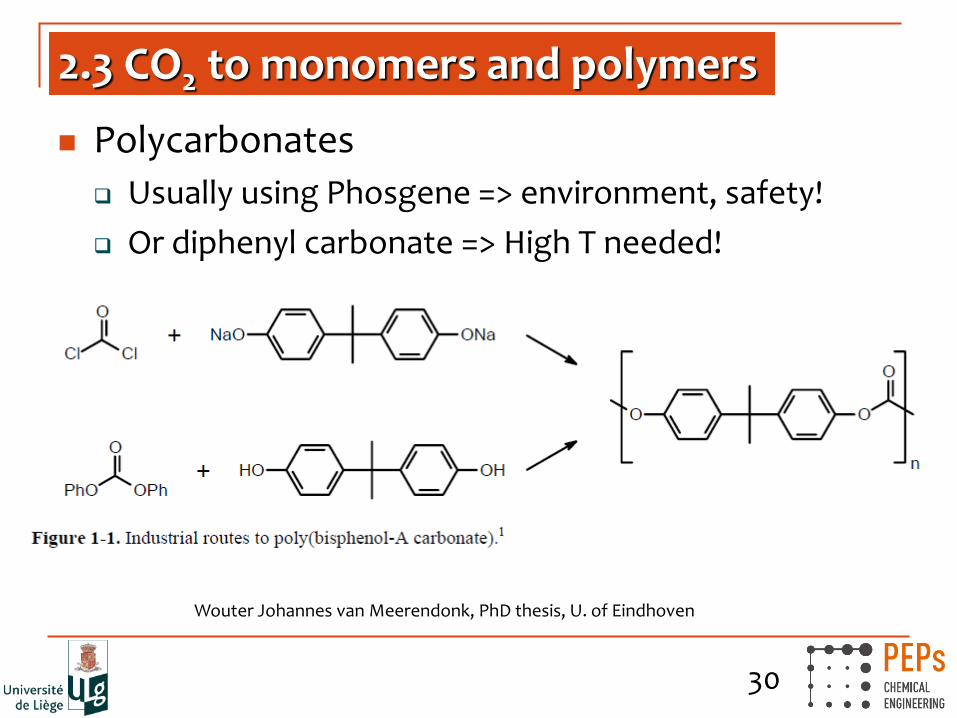
2.3 CO2 to monomers and polymers
Polycarbonates
Usually using Phosgene => environment, safety!
Or diphenyl carbonate => High T needed!
Wouter Johannes van Meerendonk, PhD thesis, U. of Eindhoven

31
2.3 CO2 to monomers and polymers
Polycarbonates
Econic’s bimetallic catalysts produce polyols form a variety of epoxides © Royal Society of Chemistry
Prof. Frey, U. of Mainz, 2016

32
2.3 CO2 to monomers and polymers
Other polyols…
40% CO2 in the final plastic
breakingenergy.com, 2014

33
2.3 CO2 to monomers and polymers
Polyurethanes
Polyols
Isocyanate
=> “Dream material”
Bayer pilot plant

34
2.3 CO2 to monomers and polymers
Polyurethanes
5000 t/a
20% CO2 in the final plastic
Little by little the customized reactor glides into the very heart of the new CO2-production-line at Bayer Material Sciences’ site in Dormagen, Germany. ChemEurope.com, June 2015

35
3. Related research topics at ULg
Transfaculty platform for CO2 re-use
About 20 researchers
50 research projects in less than 10 years
Specific equipment, unique in Wallonia
Capture
Solvent degradation
Modeling
Transformation
Methanol Molecules Monomers Polymers
Processing
Solvent Extraction Synthesis Materials Foaming
Pharma/biomaterials
Anti-solvent process Impregnation
Capsuling Micronization Sterilisation
Life Cycle Analysis
Industrialization
Intensification Process design Reactor design
Modeling

36
3.1 Post-combustion CO2 capture
Acceleration of solvent degradation to mimic industrial degradation
Mass transfer?
Metal ions ?
Inhibitors ?
[1] Léonard et al., 2014. International Journal of Greenhouse Gas Control 30, 171. DOI: 10.1016/j.ijggc.2014.09.014
Pressure ?
Temperature ?
Flue gas composition ?

37
3.1 Post-combustion CO2 capture
=> 21% degradation after 7 days vs. 4% loss in 45 days (Pilot vs. lab)
=> Similar degradation products (GC spectra)! => Identification and quantification of influence parameters => Kinetic model for degradation reactions
Léonard et al., 2014. DOI 10.1002/cjce.22094

38
Modelling of CO2 capture with assessment of solvent degradation
DOI:10.1021/ie5036572
DOI: 10.1016/j.compchemeng.2015.05.003
3.1 Post-combustion CO2 capture
39
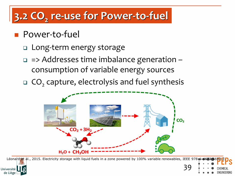
3.2 CO2 re-use for Power-to-fuel
Power-to-fuel
Long-term energy storage
=> Addresses time imbalance generation – consumption of variable energy sources
CO2 capture, electrolysis and fuel synthesis
Léonard et al., 2015. Electricity storage with liquid fuels in a zone powered by 100% variable renewables, IEEE 978-1-4673-6692-2.

40
3.2 CO2 re-use for Power-to-fuel
Why liquid fuels?
High energy density at ambient conditions 22.4 MJ/kg (methanol) vs. < 1 MJ/kg (batteries, PHS)
17.8 MJ/L vs. 0.01 – 0.03 MJ/L (H2, CH4)
CO2 neutral if air capture and renewable energies
Flexibility of use Back to electricity
Transportation fuel (can contribute to
displace fossil fuels in mobile applications)
=> Cheap long-term energy storage
=> Easy transportation
Stena Teknik

41
3.2 CO2 re-use for Power-to-fuel
Energy system analysis
Study of an electricity zone powered with 100% variable renewables and storage units Second and minute scale for frequency regulation
Inter-seasonal scale: power-to-gas, power-to-fuel
Reasonable electricity cost (83.4 €/MWh)
Léonard et al., 2015. Electricity storage with liquid fuels in a zone powered by 100% variable renewables, IEEE 978-1-4673-6692-2.
42
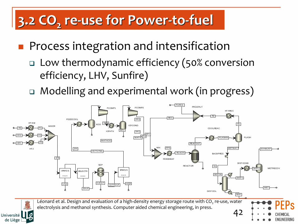
3.2 CO2 re-use for Power-to-fuel
Process integration and intensification
Low thermodynamic efficiency (50% conversion efficiency, LHV, Sunfire)
Modelling and experimental work (in progress)
REQUIL
1RWGS
HT2
HT1
MIXER
SEP
RSTOIC
2ELECTR
REQUIL
3RWGS
DISTCOL
METRECOV
DISTCOND
PRGSPLIT
HTXREC
FLASH
COOLREAC
FEEDHEAT
FCOMP1
MIX
FCOMP2
ICFCONDKOD
ICFHTX
FEEDCOOL
REACTOR
HTXH2
BACKPRES
1IN
2IN
LIQ1
F3
CO2 F2
H2O
H2
2OUT
O2OUTCATHOUT
HOTSYNG
LIQ3
REACIN
REACOUT
DIST IN
DIST1
WAT
DIST2
EXHAUST
MET
R2REC
PURGE
R1
FLASHIN
FP5
MF3
FP1FP4
FP3
FP2
WATIC
MF2
WATKOD
S1
F1
METWAT
Léonard et al. Design and evaluation of a high-density energy storage route with CO2 re-use, water electrolysis and methanol synthesis. Computer aided chemical engineering, in press.

43
3.2 CO2 reuse: microalgae culture Photobioreactor designed to cultivate microalgae
encapsulated in an hybrid matrix (beads)
T° O2 CO2 pH nutrients
UV
Photobioreactor modelling and scale up based on a coupled characterisation of : - Liquid and solid phase
hydrodynamics; - Light distribution; - Biological activity

44 44
3.3 Hydrodynamics in multiphase systems
Solid waste and flue gas treatment
Aerosol capture, VOC adsorption, CO2 capture
VOC adsorption on activated carbon filter
Visualisation of adsorption front by X-ray microtomography

45 45
3.3 Hydrodynamics in multiphase systems
Use and development of non invasive techniques to characterize phases distribution in multiphase systems and to visualize flows
Packed columns (from 0.1 to 0.6 m diameter)
- X-ray tomography (420 kV)
Bubble columns
- Particle Image Velocimetry (biphasic)
- Parietal probes
- Optical probes

46 46
3.3 Hydrodynamics in multiphase systems
Large scale, high energy X-ray tomography setup
Cold mock-ups of packed columns (Ø : 0.1 – 0.4 m)
(h : 2 – 4 m)
Examples of application
Absorption columns
Adsorption beds (Active Carbon)
Distillation and reactive distillation packings
Fixed bed bioreactors

47
molecules
drops
lab-cells for
single drops
extraction column
interfaces
Understanding for the fundamentals
of mass and momentum transfer ...
… for the development and scale-up
of new extraction processes
3.4 Solvent&reactive extraction: on all scales

48 48
3.5 Life cycle analysis
Life Cycle Assessment, environmental reporting Evaluation of the environmental impact of processes
Development of databases
Academic research + external studies
Participation to several regional and European projects
Training programs
References
Knauf Insulation, Prayon, Intradel Total Petrochemicals, Materia Nova, Pierre et marbres de Wallonie, Aseptic Technologies …
49
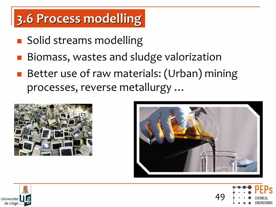
3.6 Process modelling
Solid streams modelling
Biomass, wastes and sludge valorization
Better use of raw materials: (Urban) mining processes, reverse metallurgy …

50
Conclusion
Integration within PEPs
Products, Environment and Processes
Department of Chemical Engineering
4 Professors + post-docs, PhDs, technical staff…

51
Thank your for your attention and welcome in Liège! http://kleesbutterfly.com/2015/03/22/where-the-heck-is-liege/
https://vimeo.com/95988841