Embed Size (px)
Citation preview
014404 Page 1
491 W. Garfield Ave., Coldwater, MI 49036
Phone: 517-279-2135
Web/live chat: www.bds-suspension.com
E-mail: [email protected]
Read and undeRstand all instRuctions and waRnings pRioR to installation of system and opeRation of vehicle.
Part#: 014404Product: 4" suspension systemApplication: 1999-2004 Jeep grand cherokee wJ
safety waRning BDS Suspension Co. recommends this system be installed by a professional technician. In addition to these instructions, professional knowledge of disassembly/ reassembly procedures and post installation checks must be known.
pRoduct safety waRning Certain BDS Suspension products are intended to improve off-road perfor-mance. Modifying your vehicle for off-road use may result in the vehicle handling differently than a factory equipped vehicle. Extreme care must be used to prevent loss of control or vehicle rollover. Failure to drive your modified vehicle safely may result in serious injury or death. BDS Suspension Co. does not recommend the combined use of suspension lifts, body lifts, or other lifting devices.
You should never operate your modified vehicle under the influence of alcohol or drugs. Always drive your modified ve-hicle at reduced speeds to ensure your ability to control your vehicle under all driving conditions. Always wear your seat belt.
pRe-installation notes1. Special literature required: OE Service Manual for model/year of vehicle. Refer to manual for proper disassembly/
reassembly procedures of OE and related components.
2. Adhere to recommendations when replacement fasteners, retainers and keepers are called out in the OE manual.
3. Larger rim and tire combinations may increase leverage on suspension, steering, and related components. When selecting combinations larger than OE, consider the additional stress you could be inducing on the OE and related components.
4. Post suspension system vehicles may experience drive line vibrations. Angles may require tuning, slider on shaft may require replacement, shafts may need to be lengthened or trued, and U-joints may need to be replaced.
5. Secure and properly block vehicle prior to installation of BDS Suspension components. Always wear safety glasses when using power tools.
6. If installation is to be performed without a hoist, BDS Suspension Co. recommends rear alterations first.
7. Due to payload options and initial ride height variances, the amount of lift is a base figure. Final ride height dimensions may vary in accordance to original vehicle attitude. Always measure the attitude prior to beginning installation.
post-installation waRnings1. Check all fasteners for proper torque. Check to ensure for adequate clearance between all rotating, mobile, fixed, and
heated members. Verify clearance between exhaust and brake lines, fuel lines, fuel tank, floor boards and wiring harness. Check steering gear for clearance. Test and inspect brake system.
2. Perform steering sweep to ensure front brake hoses have adequate slack and do not contact any rotating, mobile or heated members. Inspect rear brake hoses at full extension for adequate slack. Failure to perform hose check/ replacement may result in component failure. Longer replacement hoses, if needed can be purchased from a local parts supplier.
3. Perform head light check and adjustment.
4. Re-torque all fasteners after 500 miles. Always inspect fasteners and components during routine servicing.
rev. 03/11/2013
014404 Page 2
paRts listPart # Qty Description034401R 2 Front coil spring034359R 2 Rear coil spring
014404 Box Kit084403R 1 Dropped pitman arm01320B 1 A-Arm spacer342701 1 Loctite - 1ml725 1 Bolt Pack
2 10mm-1.50 x 65mm bolt 2 10mm-1.50 prevailing torque nut4 3/8"USSflatwasher4 8mm-1.25 x 100mm bolt4 5/16"USSflatwasher3 14mm-2.00 x 80mm bolt3 9/16"SAEflatwasher1 1/8" x 1-1/4" cotter pin
Adjustable Lower Control ArmsA176 2 Adjustable flex LCA01421 4 1/4" LCA axle spacer washer01422 4 1/8" LCA frame spacer washer
Bump Stop Parts01489B 2 Front bump stop spacer439 1 Bolt Pack
2 3/8"-16 x 2-1/2" bolt
2 3/8"USSflatwasher1 3/8"-16x1"self-tappingbolt
3296 2 Rear bump stop spacer726 1 Bolt Pack
4 10mm-1.50 x 140mm bolt4 10mm-1.50 x 100mm bolt8 3/8"USSflatwasher
Sway Bar Link Parts01473 2 Rear sway bar linkSB58BK 4 5/8 ID Hourglass Bushing45313 2 .625 x .109 x 1.375 Sleeve62147 2 .625 x .075 x 1.375 Sleeve
Track Bar Relocation01491B 1 Track bar bracket727 1 Bolt Pack
1 12mm-1.75 x 75mm bolt 1 12mm-1.75 prevailing torque nut1 1/2"-13 x 3" bolt1 1/2"-13 x 1-1/2" bolt6 1/2"SAEflatwasher2 10mm-1.50 x 120mm bolt2 3/8"USSflatwasher2 3/16"thickwasher
Transfer Case DropYJTC5 8 Transfer case spacer
014404 Page 3
installation instRuctionsPre-Installation1. Measure from the center of the wheel up to the bottom edge of the wheel opening.
LF______ RF______ LR______ RR______2. Located and adjust the center-to-center length of the new lower control arms (A176) to 16-1/8". This is a starting
point and may need to be adjusted at the end of the installation to achieve desired caster/front driveline angles. Leave the jam nut loose at this time.
Front Installation1. Park the vehicle on a clean, flat surface and block the rear wheels for safety.
2. Raise the front of the vehicle and support with jack stands under the frame behind the front lower control arm pockets.
3. Remove the wheels.
4. Remove the shocks. Discard the hardware and the shocks.
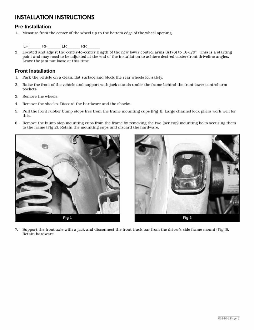
5. Pull the front rubber bump stops free from the frame mounting cups (Fig 1). Large channel lock pliers work well for this.
6. Remove the bump stop mounting cups from the frame by removing the two (per cup) mounting bolts securing them to the frame (Fig 2). Retain the mounting cups and discard the hardware.
Fig 1
Fig 2
7. Support the front axle with a jack and disconnect the front track bar from the driver’s side frame mount (Fig 3). Retain hardware.

014404 Page 4
Fig 3
Fig 4
8. Disconnect the front sway bar links from the axle. Retain the mounting hardware.
9. Remove the cotter pin and nut from the drag link-to-pitman arm tie rod end. Dislodge the end from the pitman arm with a pickle fork or other appropriate puller.
10. Lower the axle just enough to allow removal of the front OE coil springs. Remove the springs from the vehicle.
11. Important: Make an indexing mark on the pitman arm and steering box sector shaft to indicate the relation-ship between the two for installation (Fig 4) Remove the pitman arm nut and washer. Using a pitman arm puller remove the pitman arm from the sector shaft.
12. Transfer the alignment mark on the OE pitman arm to the corresponding position on the new pitman arm (Fig 5).
Fig 5
13. Install the new pitman arm of the sector shaft by aligning the marks. Fasten the arm with the OE nut and washer and torque to 185 ft-lbs.
014404 Page 5
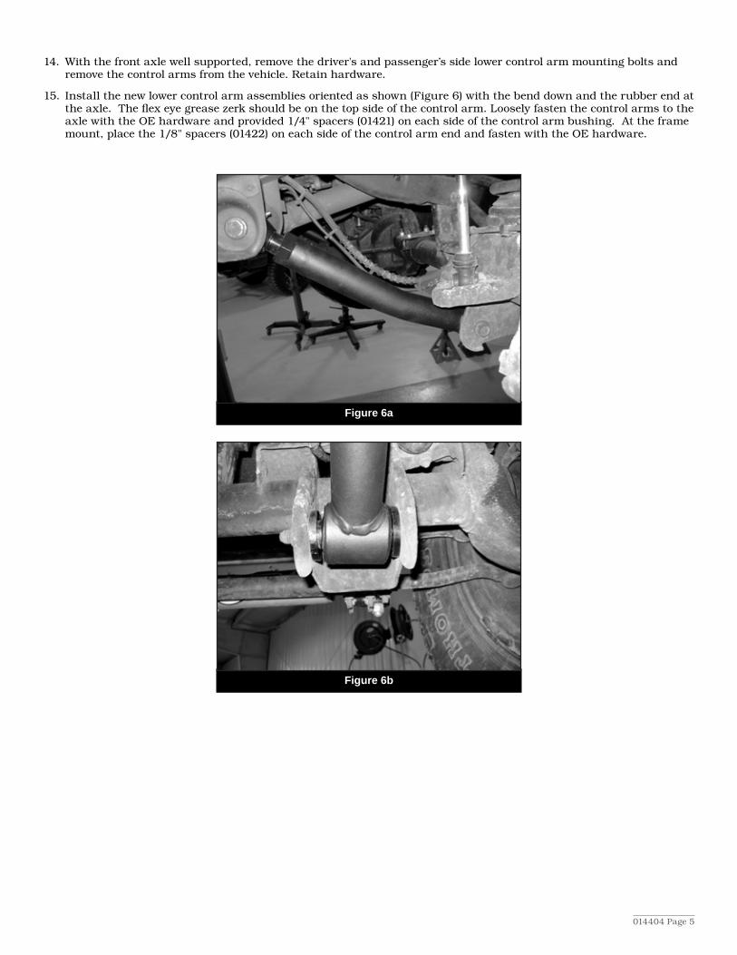
14. With the front axle well supported, remove the driver's and passenger’s side lower control arm mounting bolts and remove the control arms from the vehicle. Retain hardware.
15. Install the new lower control arm assemblies oriented as shown (Figure 6) with the bend down and the rubber end at the axle. The flex eye grease zerk should be on the top side of the control arm. Loosely fasten the control arms to the axle with the OE hardware and provided 1/4" spacers (01421) on each side of the control arm bushing. At the frame mount, place the 1/8" spacers (01422) on each side of the control arm end and fasten with the OE hardware.
Figure 6a
Figure 6b
014404 Page 6
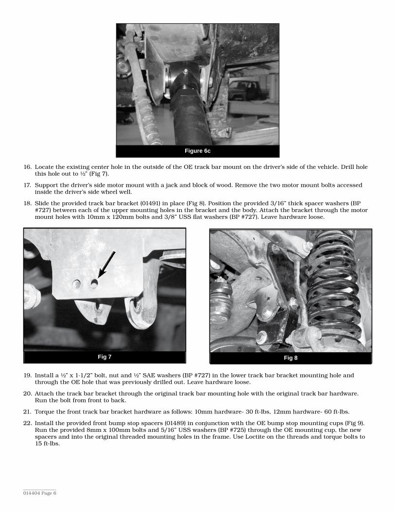
Figure 6c
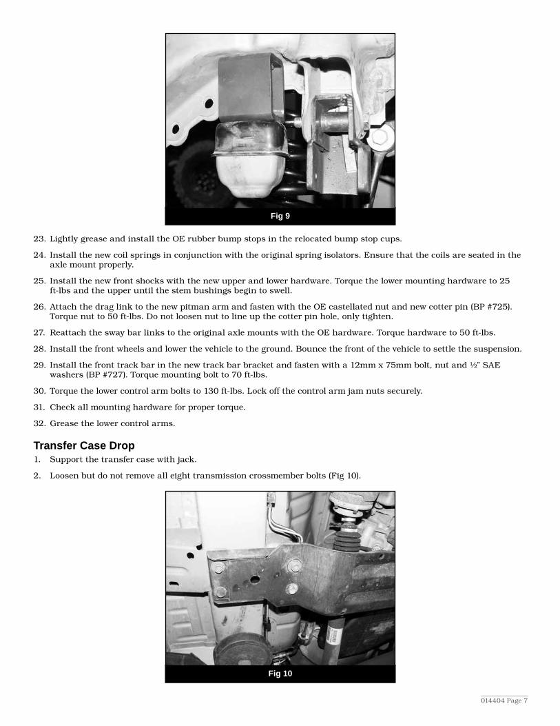
16. Locate the existing center hole in the outside of the OE track bar mount on the driver’s side of the vehicle. Drill hole this hole out to ½” (Fig 7).
17. Support the driver’s side motor mount with a jack and block of wood. Remove the two motor mount bolts accessed inside the driver’s side wheel well.
18. Slide the provided track bar bracket (01491) in place (Fig 8). Position the provided 3/16” thick spacer washers (BP #727) between each of the upper mounting holes in the bracket and the body. Attach the bracket through the motor mount holes with 10mm x 120mm bolts and 3/8” USS flat washers (BP #727). Leave hardware loose.
Fig 7 Fig 8
19. Install a ½” x 1-1/2” bolt, nut and ½” SAE washers (BP #727) in the lower track bar bracket mounting hole and through the OE hole that was previously drilled out. Leave hardware loose.
20. Attach the track bar bracket through the original track bar mounting hole with the original track bar hardware. Run the bolt from front to back.
21. Torque the front track bar bracket hardware as follows: 10mm hardware- 30 ft-lbs, 12mm hardware- 60 ft-lbs.
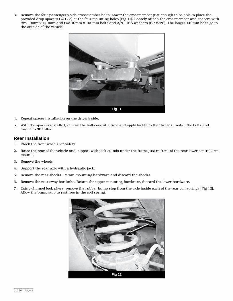
22. Install the provided front bump stop spacers (01489) in conjunction with the OE bump stop mounting cups (Fig 9). Run the provided 8mm x 100mm bolts and 5/16” USS washers (BP #725) through the OE mounting cup, the new spacers and into the original threaded mounting holes in the frame. Use Loctite on the threads and torque bolts to 15 ft-lbs.
014404 Page 7
Fig 9
23. Lightly grease and install the OE rubber bump stops in the relocated bump stop cups.
24. Install the new coil springs in conjunction with the original spring isolators. Ensure that the coils are seated in the axle mount properly.
25. Install the new front shocks with the new upper and lower hardware. Torque the lower mounting hardware to 25 ft-lbs and the upper until the stem bushings begin to swell.
26. Attach the drag link to the new pitman arm and fasten with the OE castellated nut and new cotter pin (BP #725). Torque nut to 50 ft-lbs. Do not loosen nut to line up the cotter pin hole, only tighten.
27. Reattach the sway bar links to the original axle mounts with the OE hardware. Torque hardware to 50 ft-lbs.
28. Install the front wheels and lower the vehicle to the ground. Bounce the front of the vehicle to settle the suspension.
29. Install the front track bar in the new track bar bracket and fasten with a 12mm x 75mm bolt, nut and ½” SAE washers (BP #727). Torque mounting bolt to 70 ft-lbs.
30. Torque the lower control arm bolts to 130 ft-lbs. Lock off the control arm jam nuts securely.
31. Check all mounting hardware for proper torque.
32. Grease the lower control arms.
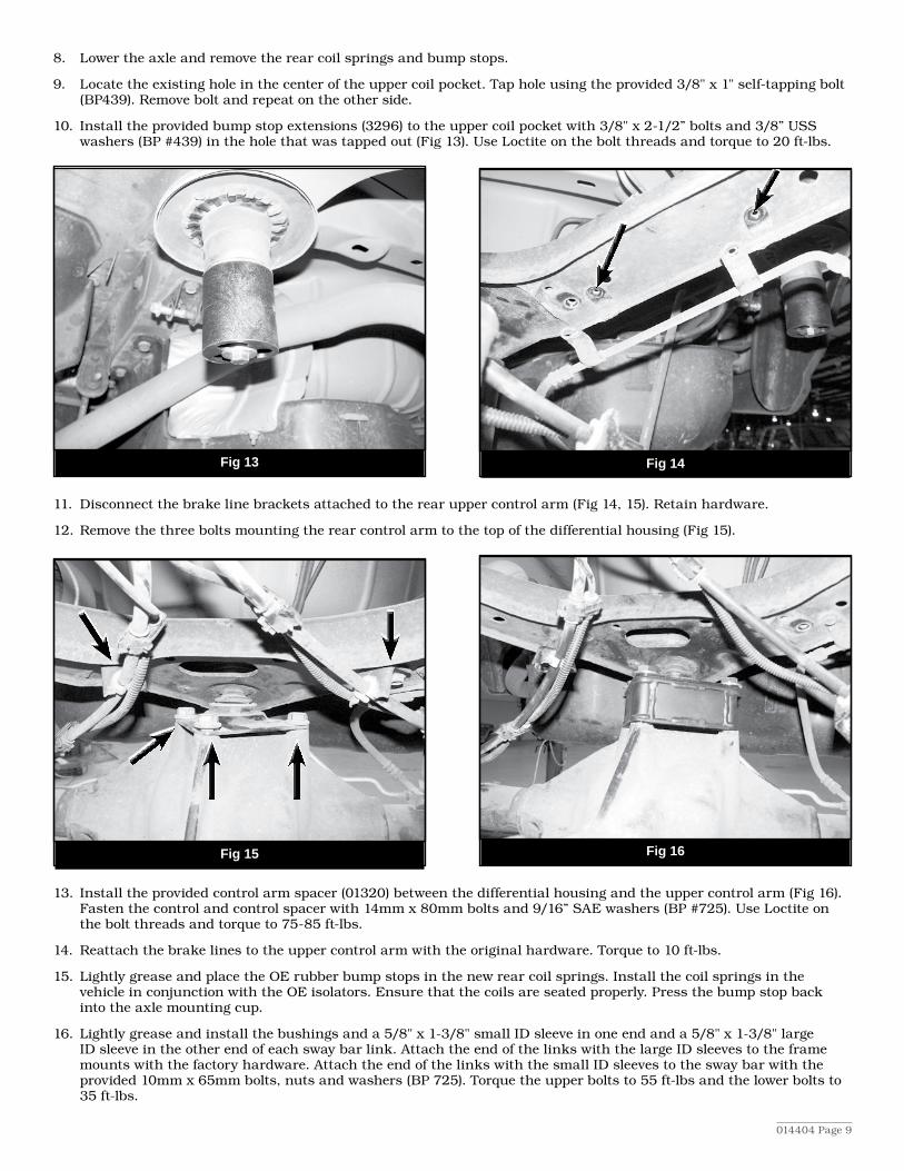
Transfer Case Drop1. Support the transfer case with jack.
2. Loosen but do not remove all eight transmission crossmember bolts (Fig 10).
Fig 10
014404 Page 8
3. Remove the four passenger’s side crossmember bolts. Lower the crossmember just enough to be able to place the provided drop spacers (YJTC5) at the four mounting holes (Fig 11). Loosely attach the crossmember and spacers with two 10mm x 140mm and two 10mm x 100mm bolts and 3/8” USS washers (BP #726). The longer 140mm bolts go to the outside of the vehicle.
Fig 11
4. Repeat spacer installation on the driver’s side.
5. With the spacers installed, remove the bolts one at a time and apply loctite to the threads. Install the bolts and torque to 30 ft-lbs.
Rear Installation1. Block the front wheels for safety.
2. Raise the rear of the vehicle and support with jack stands under the frame just in front of the rear lower control arm mounts.
3. Remove the wheels.
4. Support the rear axle with a hydraulic jack.
5. Remove the rear shocks. Retain mounting hardware and discard the shocks.
6. Remove the rear sway bar links. Retain the upper mounting hardware, discard the lower hardware.
7. Using channel lock pliers, remove the rubber bump stop from the axle inside each of the rear coil springs (Fig 12). Allow the bump stop to rest free in the coil spring.
Fig 12
014404 Page 9
8. Lower the axle and remove the rear coil springs and bump stops.
9. Locate the existing hole in the center of the upper coil pocket. Tap hole using the provided 3/8" x 1" self-tapping bolt (BP439). Remove bolt and repeat on the other side.
10. Install the provided bump stop extensions (3296) to the upper coil pocket with 3/8" x 2-1/2” bolts and 3/8” USS washers (BP #439) in the hole that was tapped out (Fig 13). Use Loctite on the bolt threads and torque to 20 ft-lbs.
Fig 13
Fig 14
11. Disconnect the brake line brackets attached to the rear upper control arm (Fig 14, 15). Retain hardware.
12. Remove the three bolts mounting the rear control arm to the top of the differential housing (Fig 15).
Fig 15 Fig 16
13. Install the provided control arm spacer (01320) between the differential housing and the upper control arm (Fig 16). Fasten the control and control spacer with 14mm x 80mm bolts and 9/16” SAE washers (BP #725). Use Loctite on the bolt threads and torque to 75-85 ft-lbs.
14. Reattach the brake lines to the upper control arm with the original hardware. Torque to 10 ft-lbs.
15. Lightly grease and place the OE rubber bump stops in the new rear coil springs. Install the coil springs in the vehicle in conjunction with the OE isolators. Ensure that the coils are seated properly. Press the bump stop back into the axle mounting cup.
16. Lightly grease and install the bushings and a 5/8" x 1-3/8" small ID sleeve in one end and a 5/8" x 1-3/8" large ID sleeve in the other end of each sway bar link. Attach the end of the links with the large ID sleeves to the frame mounts with the factory hardware. Attach the end of the links with the small ID sleeves to the sway bar with the provided 10mm x 65mm bolts, nuts and washers (BP 725). Torque the upper bolts to 55 ft-lbs and the lower bolts to 35 ft-lbs.
014404 Page 10
17. Install the new shocks with the original hardware. At the top mount install the provided 5/8” spacer washers on the shock sleeve to allow for proper compress of the shock bushing.
18. Install wheels and lower the vehicle to the ground.
19. Check all hardware for proper torque.
20. Check hardware after 500 miles.
21. Center steering wheel.
Note:Frontwheelshimmy—somevehiclesmayexperiencefrontwheelshimmy.Thisisnotawarrantyissue,butratheraninherentOEdesignissuewiththe99-04WJ.Wehavefoundthat4-5degreesofcastercombinedwithmaxtoeinsettingwillhelpeliminatethisproblem.Specifictireandwheelcombinationsmayalsoinducesteeringshimmy.Inmostcases,alignmentand/ortireandwheelchangeswillcorrectthisproblem.Theadditionofadualsteeringstabilizersetuphasalsobeenfoundtobeveryeffectiveincontrollingwheelshimmy.BDSSuspensionassumesnoincurredexpensesassociatedwiththecorrectionofthisproblem.
For questions, technical support and warranty issues relating to this BDS Suspension product, please contact your dis-tributor/installer before contacting BDS Suspension directly.
Sold/Installed by:
notice to dealeR/installeRThese instructions, the warning card, and included decals must be given to the owner of this BDS Suspension product.