Embed Size (px)
Citation preview

DR® VERSA-PRO™ Z-MOWER
SAFETY & OPERATING INSTRUCTIONS
READ AND UNDERSTAND THIS MANUAL AND ALL INSTRUCTIONS BEFORE OPERATING THIS MOWER.
Serial No. ________________
Order No. ________________

ii DR® VERSA-PRO™ Z-MOWER
Congratulations on your purchase of a new DR VERSA-PRO Z-MOWER!
We have done our utmost to ensure that your DR VERSA-PRO Z-MOWER will be one of the most trouble-free and satisfying pieces of equipment you have ever owned. Please let us know of any questions you may have. We want to answer them as quickly as possible. When you do call, please have your serial number and/or order number handy. For technical assistance, please visit our website at www.DRPower.com or call Toll-Free 1-800-DR-OWNER (376-9637) and one of our Technical Support Representatives will be happy to help you. We also hope to hear from you on how much you like your new helper. In addition, please tell your friends about your new DR VERSA-PRO Z-MOWER! Having DR Owners spread the word about our products and our way of doing business is the best advertising we can have, and the best way to help us provide even better service in the years to come.
Thanks once again!
for all of us at DR Power Equipment
SALES MANAGER
COPYRIGHT ©2008 Country Home Products, Inc. All rights reserved.
DR® Power Equipment A division of Country Home Products® 75 Meigs Road Vergennes, VT 05491 Toll-Free phone: 1-800-DR-OWNER (376-9637) Fax: 1-802-877-1213 Website: www.DRPower.com

CONTACT US AT www.DRPower.com or CALL TOLL FREE 1-800-DR-OWNER iii
Table of Contents CHAPTER 1............................................................................................................................. 1
INTRODUCING THE DR VERSA-PRO Z-MOWER......................................................... 1 Conventions used in this manual ................................................................................... 1 Specifications................................................................................................................... 2 Serial Number.................................................................................................................. 2
CHAPTER 2............................................................................................................................. 3 GENERAL SAFETY RULES............................................................................................... 3 Labels ............................................................................................................................... 3 Protecting Yourself and Those Around You ................................................................... 5 Operating the Mower Safely............................................................................................ 5 Operating on Slopes and Uneven Terrain ...................................................................... 7 Safety for Children ........................................................................................................... 7 Safety with Gasoline-Powered Machines........................................................................ 8 A Note to All Users .......................................................................................................... 9 Additional Information and Potential Changes.............................................................. 9
CHAPTER 3........................................................................................................................... 11 SETTING UP YOUR DR VERSA-PRO Z-MOWER......................................................... 11 DR VERSA-PRO Z-MOWER Controls and Features ..................................................... 12 Unpacking the Mower ................................................................................................... 14 Adding Oil and Gasoline ............................................................................................... 15 Check the Tire Pressure................................................................................................. 15 Connecting the Battery Wire ......................................................................................... 16
CHAPTER 4........................................................................................................................... 17 OPERATING YOUR DR VERSA-PRO Z-MOWER ......................................................... 17 The Pre-Start Safety Check ............................................................................................ 17 Before Starting the Engine............................................................................................. 18 Starting the Engine ........................................................................................................ 18 Stopping the Engine ...................................................................................................... 18 Operating the VERSA-PRO Z-MOWER......................................................................... 19 Throttle Control ............................................................................................................. 19 Speed Control ................................................................................................................ 19 Control Handles............................................................................................................. 19 Stopping the Mower ...................................................................................................... 20 Stopping the Blades....................................................................................................... 20 Mowing .......................................................................................................................... 20 Practice Before Mowing................................................................................................. 20 Mowing Speed ............................................................................................................... 21 Mowing Height .............................................................................................................. 21 Mowing Tips .................................................................................................................. 21 Obstacle Tips ................................................................................................................. 21 Slopes............................................................................................................................. 22 If the machine gets hung up ......................................................................................... 22 Reverse ........................................................................................................................... 22 Cutting in Wet and Heavy Growth ................................................................................ 22 Hand Pushing the Mower ............................................................................................. 23 Checking the Hydraulic Fluid ........................................................................................ 24 Changing Operator Positions........................................................................................ 24
CHAPTER 5........................................................................................................................... 25 ADJUSTING AND MAINTAINING THE DR VERSA-PRO Z-MOWER......................... 25 Regular Maintenance Check List................................................................................... 25 Lubrication ..................................................................................................................... 27 Removing the Engine Oil and Filter .............................................................................. 28 Removing and Replacing the Belts ............................................................................... 29 Adjusting the Engine to Deck Belt ................................................................................ 31 Adjusting the Hydro Drive Belt ..................................................................................... 31 Removing and Replacing the Blades............................................................................. 32

iv DR® VERSA-PRO™ Z-MOWER
Removing the Deck........................................................................................................ 33 Adjusting the Deck Height ............................................................................................ 34 Leveling the Deck........................................................................................................... 35 Adjusting the Parking Brake .......................................................................................... 35 Adjusting the Control Panel .......................................................................................... 36 Adjusting the Hydro Tracking ....................................................................................... 37 Adjusting the Neutral Setting........................................................................................ 39 Replacing the Hydro Fluid Filters.................................................................................. 40 Battery Care.................................................................................................................... 41 Charging the Battery ...................................................................................................... 41 Disposing of the Battery Responsibly ........................................................................... 42 Recycling a Used Battery ............................................................................................... 42 End of Season and Storage ........................................................................................... 43
CHAPTER 6........................................................................................................................... 45 TROUBLESHOOTING................................................................................................... 45 Troubleshooting Table................................................................................................... 45
CHAPTER 7........................................................................................................................... 48 PARTS LISTS, SCHEMATIC DIAGRAMS AND WARRANTY........................................ 48 Parts List - Engine to Chassis........................................................................................ 48 Schematic - Engine to Chassis ...................................................................................... 49 Parts List - Chassis Foot Lift Assembly......................................................................... 50 Schematic - Chassis Foot Lift Assembly ....................................................................... 51 Parts List - Lower Chassis Assembly............................................................................. 52 Schematic - Lower Chassis Assembly ........................................................................... 53 Parts List - Deck Lift Arm Assembly.............................................................................. 54 Schematic - Deck Lift Arm Assembly ............................................................................ 55 Parts List - Deck to Chassis Assembly .......................................................................... 56 Schematic - Deck to Chassis Assembly ........................................................................ 57 Parts List - Deck 48" ...................................................................................................... 58 Schematic - Deck 48"..................................................................................................... 59 Parts List - Deck 52" ...................................................................................................... 60 Schematic - Deck 52"..................................................................................................... 61 Parts List - Seat Pedestal Assembly .............................................................................. 62 Schematic - Seat Pedestal Assembly............................................................................. 63 Parts List - Arm Rest Assembly w/Rear Guards ........................................................... 64 Schematic - Arm Rest Assembly w/Rear Guards.......................................................... 65 Parts List - Control Panel............................................................................................... 66 Schematic - Control Panel ............................................................................................. 67 Parts List - Parking Brake Assembly.............................................................................. 68 Schematic - Parking Brake Assembly ............................................................................ 69 Parts List - Control Arm Assembly ................................................................................ 70 Schematic - Control Arm Assembly .............................................................................. 71 Parts List - Wheel Drive Assembly ................................................................................ 72 Schematics - Wheel Drive Assembly............................................................................. 73 Parts List - Hydro Tank Assembly ................................................................................. 74 Parts List - Hydro Belt Configuration............................................................................ 74 Schematics - Hydro Tank Assembly and Hydro Belt Configuration ............................ 75 Parts List and Schematic - Front Caster Assembly....................................................... 76 Warranty......................................................................................................................... 79

CONTACT US AT www.DRPower.com or CALL TOLL FREE 1-800-DR-OWNER 1
CHAPTER 1 INTRODUCING THE DR VERSA-PRO Z-MOWER
This manual will help you set up and safely operate your new DR VERSA-PRO Z-MOWER. Careful adherence to the safety and operating instructions in this manual will ensure many years of productive use. Please let us know of any questions you may have. We want to answer them as quickly as possible. When you do call, please have your serial number and/or order number handy. For technical assistance, please visit our website at www.DRPower.com or call Toll-Free 1-800-DR-OWNER (376-9637) and one of our Technical Support Representatives will be happy to help you.
Conventions used in this manual
THIS INDICATES A HAZARDOUS SITUATION, WHICH, IF NOT AVOIDED, COULD RESULT IN DEATH OR SERIOUS INJURY.
Tip: This is a helpful hint to guide you in getting the most out of your DR VERSA-PRO Z-MOWER.
Tools Needed: This indicates you will need a special tool to perform a maintenance function on your Mower.
NOTE: This information may be helpful to you. If you are ever unsure about an action you are about to take, don’t do it. Visit DR Power Equipment’s website at www.DRPower.com or call Toll-Free at 1-800-DR-OWNER (376-9637) for help or information.
THIS INDICATES A HAZARDOUS SITUATION, WHICH, IF NOT AVOIDED, COULD RESULT IN MINOR OR MODERATE INJURY.
THIS INFORMATION IS IMPORTANT IN THE PROPER USE OF YOUR MACHINE. FAILURE TO FOLLOW THIS INSTRUCTION COULD RESULT IN DAMAGE TO YOUR MACHINE OR PROPERTY.
2 DR® VERSA-PRO™ Z-MOWER
Specifications
48" Wide Model 52" Wide Model Engine Briggs & Stratton, 19.5 HP Briggs & Stratton, 22 HP Type OHV, AVS, ELS OHV, AVS, ELS Fuel Tank, Gasoline, Unleaded 5 Gallons 5 Gallons
Hydraulic Fluid Amisol, 30 Weight, Synthetic, or equivalent
Amisol, 30 Weight, Synthetic, or equivalent
Hydraulic Fluid Tank Metal, 5.5 Qts. (4.28L) Metal, 5.5 Qts. (4.28L) Hydraulic Fluid Filter (2) 25 Micron 25 Micron Rear Tires 23" x 8.5" x 12" Turf 23" x 10.5" x 12" Turf Front Tires 13" x 5" x 6" Ribbed 13" x 5" x 6" Ribbed Speed 0 to 13 MPH 0 to 13 MPH Electrical System 12-volt, Key Start 12-volt, Key Start Deck 48", Welded 10 Gauge steel 52", Welded 10 Gauge Steel Parking Brake Drum Drum Cutting Height 1.5" to 4.5" 1.5" to 4.5" Machine Overall Width 48" 52" Machine Overall Length 70" 70" Machine Overall Height 48" 48" Machine Weight 820 lbs. 835 lbs.
Shipping Specifications Shipping Weight 960 lbs. 975 lbs. Shipping Dimensions 73" x 50" x 54" 73" x 55" x 54"
Serial Number A Serial Number (S/N) is used to identify your machine. The number is located on the left side of the Frame just beneath the Fuel Tank. For your convenience and ready reference, enter the Serial Number here and on the cover of this manual. S/N:_____________________________

CONTACT US AT www.DRPower.com or CALL TOLL FREE 1-800-DR-OWNER 3
CHAPTER 2 GENERAL SAFETY RULES
READ THIS SAFETY & OPERATING INSTRUCTIONS MANUAL BEFORE YOU USE THE DR VERSA-PRO Z-MOWER. BECOME FAMILIAR WITH THE SERVICE RECOMMENDATIONS TO ENSURE THE BEST PERFORMANCE FROM YOUR MOWER.
Labels
Your DR VERSA-PRO Z-MOWER carries prominent labels as reminders for its proper and safe use. Shown below are copies of all the labels that appear on the equipment. Take a moment to study them and make a note of their location on your DR VERSA-PRO Z-MOWER as you assemble and before you operate the machine. Replace damaged or missing safety and information labels immediately.
Use caution operating the machine on slopes.
Keep body parts away from the mower blade.
Always wear safety glasses or goggles while operating the machine.
Remove all objects that could be thrown by the mower blade.
Do not operate the machine near people or animals.
Read the Safety & Operating Instructions Manual.

4 DR® VERSA-PRO™ Z-MOWER
This label reminds you operate the machine safely and provides helpful operating information. (#241331)
To avoid injury, keep your hands and feet away from the spinning blade. (#136491)
(#225071)
(#228731)
(#241311)

CONTACT US AT www.DRPower.com or CALL TOLL FREE 1-800-DR-OWNER 5
Protecting Yourself and Those Around You
THIS IS A HIGH-POWERED MACHINE, WITH MOVING PARTS OPERATING WITH HIGH ENERGY AT HIGH SPEEDS. YOU MUST USE PROPER CLOTHING AND SAFETY GEAR WHEN OPERATING THIS MACHINE TO PREVENT OR MINIMIZE THE RISK OF SEVERE INJURY. THIS MACHINE CAN CUT, AND SEVER PARTS OF YOUR BODY IF THEY BECOME IN CONTACT WITH THE MOVING BLADES. ALWAYS TAKE THE FOLLOWING PRECAUTIONS WHEN OPERATING THIS MACHINE: • ALWAYS WEAR PROTECTIVE GOGGLES OR SAFETY GLASSES WITH SIDE SHIELDS WHILE MOWING TO
PROTECT YOUR EYES FROM POSSIBLE THROWN DEBRIS. • WEAR SHOES WITH NON-SLIP TREADS WHEN USING YOUR DR VERSA-PRO Z-MOWER. IF YOU HAVE
SAFETY SHOES, WE RECOMMEND WEARING THEM. DO NOT USE THE MACHINE WHILE BAREFOOT OR WEARING OPEN SANDALS.
• AVOID WEARING LOOSE CLOTHING OR JEWELRY, WHICH WILL CATCH ON THE MOWER’S MOVING PARTS.
Operating the Mower Safely
THIS IS A HIGH-POWERED MACHINE, WITH MOVING PARTS OPERATING WITH HIGH ENERGY AT HIGH SPEEDS. YOU MUST OPERATE THE MACHINE SAFELY. UNSAFE OPERATION CAN CREATE A NUMBER OF HAZARDS FOR YOU, AS WELL AS ANYONE ELSE IN THE NEARBY AREA. THE PURPOSE OF THIS MACHINE IS TO PERFORM WORK. THE INTENTION OF THIS EQUIPMENT IS NOT FOR SPORT OR RECREATION. ALWAYS TAKE THE FOLLOWING PRECAUTIONS WHEN USING THIS MACHINE: • NEVER ALLOW PEOPLE WHO ARE UNFAMILIAR WITH THESE INSTRUCTIONS TO USE THE DR VERSA-
PRO Z-MOWER. • KEEP BYSTANDERS AT LEAST 100 FEET AWAY FROM YOUR WORK AREA AT ALL TIMES. THE MOWER
CAN THROW OBJECTS FAR AND AT GREAT SPEEDS. TO BE SAFE, DO NOT OPERATE THE MACHINE NEAR SMALL CHILDREN OR PETS, AND NEVER ALLOW CHILDREN TO OPERATE THE MOWER. DISENGAGE THE BLADES AND STOP THE ENGINE WHEN ANOTHER PERSON OR PET APPROACHES.
• NEVER CARRY PASSENGERS ON YOUR VERSA-PRO Z-MOWER. • CLEAR THE AREA OF OBJECTS SUCH AS ROCKS, TOYS, WIRE, BONES, STICKS ETC., WHICH COULD BE
PICKED UP AND THROWN BY THE BLADES. • KEEP YOUR HANDS AND FEET AWAY FROM THE BLADES, BELTS, CHAINS, BLADE PULLEYS, AND
CONCEALED AREAS WHILE THE ENGINE IS RUNNING. NEVER REACH UNDER THE DECK OR GRAB HOLD OF ANY PART OF THE DECK WHEN THE ENGINE IS RUNNING.

6 DR® VERSA-PRO™ Z-MOWER
• ALWAYS DISENGAGE THE BLADES, SET THE PARKING BRAKE, SHUT-OFF THE ENGINE, AND REMOVE THE KEY WHENEVER YOU LEAVE THE MACHINE. REMOVE THE SPARK PLUG WIRE(S) BEFORE ADJUSTING THE MACHINE. IF YOU HAVE TO STOP TO REMOVE GRASS OR DEBRIS FROM THE UNDERSIDE OF THE DECK, ALWAYS DISCONNECT THE SPARK PLUG WIRE(S) FIRST.
• THE EXHAUST AREA ON THE ENGINE BECOMES VERY HOT WITH USE. ALLOW THE ENGINE TO COOL BEFORE DOING MAINTENANCE OR MAKING ADJUSTMENTS.
• KEEP COMBUSTIBLE SUBSTANCES AWAY FROM THE ENGINE. • WHEN OPERATING OVER UNEVEN TERRAIN AND SLOPES, USE EXTREME CAUTION TO ENSURE
SOLID AND FIRM FOOTING. KEEP A FIRM HOLD ON THE CONTROL HANDLES AND WALK, NEVER RUN.
• STOP THE BLADES WHEN CROSSING GRAVEL DRIVES, WALKS, OR ROADS. • USE EXTRA CAUTION WHEN MOWING IN WET OR SLIPPERY CONDITIONS. • ALWAYS OPERATE THE MOWER FROM THE OPERATOR’S POSITION, IN THE DRIVER’S SEAT OR
BEHIND THE MOWER. NEVER PASS OR STAND ON THE DISCHARGE (RIGHT) SIDE OR IN FRONT OF MACHINE WHEN THE ENGINE IS RUNNING.
• LOOK DOWN, AND BEHIND BEFORE AND WHILE MOVING BACKWARDS. • DO NOT, UNDER ANY CONDITIONS, REMOVE, BEND, CUT, FIT, WELD, OR OTHERWISE ALTER
STANDARD PARTS ON THE DR VERSA-PRO Z-MOWER. THIS INCLUDES ALL SHIELDS AND GUARDS. MODIFICATIONS TO YOUR MACHINE COULD CAUSE PERSONAL INJURIES AND PROPERTY DAMAGE AND WILL VOID YOUR WARRANTY.
• IF THE MACHINE STARTS TO MAKE AN UNUSUAL NOISE OR VIBRATION, IMMEDIATELY SHUT OFF THE ENGINE, DISCONNECT THE SPARK PLUG WIRE(S), AND ALLOW ALL MOVING PARTS TO COME TO A COMPLETE STOP. VIBRATION IS GENERALLY A WARNING OF TROUBLE. INSPECT FOR CLOGGING OR DAMAGE. CLEAN AND REPAIR AND/OR REPLACE DAMAGED PARTS.
• WHILE USING THE DR VERSA-PRO Z-MOWER, DO NOT HURRY OR TAKE THINGS FOR GRANTED. WHEN IN DOUBT ABOUT THE EQUIPMENT OR YOUR SURROUNDINGS, STOP THE MACHINE AND TAKE THE TIME TO LOOK THINGS OVER. MAKE SURE THAT YOU HAVE 100% CONTROL OF THE MOWER AT ALL TIMES.
• DO NOT OPERATE THE MACHINE WHEN UNDER THE INFLUENCE OF ALCOHOL, DRUGS, OR MEDICATION.
• WATCH FOR TRAFFIC WHEN MOWING NEAR ROADWAYS. • WHILE OPERATING, STAY ALERT FOR HOLES, ROCKS, OR ROOTS, WHICH MAY CAUSE DAMAGE TO
THE EQUIPMENT OR INJURY TO THE OPERATOR. KEEP AT LEAST THREE (3) FEET AWAY FROM DROP-OFFS, DITCHES, CREEKS, CULVERTS, WASHOUTS AND PUBLIC HIGHWAYS.
• USE THE MACHINE IN DAYLIGHT OR GOOD ARTIFICIAL LIGHT.

CONTACT US AT www.DRPower.com or CALL TOLL FREE 1-800-DR-OWNER 7
Operating on Slopes and Uneven Terrain
SLOPES ARE A MAJOR FACTOR RELATED TO TIP-OVER, AND SLIP AND FALL ACCIDENTS, WHICH CAN RESULT IN SEVERE INJURY. OPERATING ON SLOPES REQUIRES CAUTION. IF YOU FEEL UNEASY ON A SLOPE, DO NOT MOW IT. ALWAYS TAKE THE FOLLOWING PRECAUTIONS WHEN USING THIS MACHINE ON SLOPES:
ALWAYS:
• REMOVE OBJECTS SUCH AS ROCKS, TREE LIMBS, ETC. • WATCH OUT FOR HOLES, RUTS, OR BUMPS. TALL GRASS CAN HIDE OBSTACLES. • MOW ACROSS THE FACE OF SLOPES IN THE WALK-BEHIND POSITION; NEVER UP AND DOWN.
EXERCISE EXTREME CAUTION WHEN CHANGING DIRECTION ON SLOPES. • REDUCE SPEED AND EXERCISE EXTREME CAUTION ON SLOPES. • OPERATE YOUR MACHINE SMOOTHLY AND AT A GROUND SPEED SLOW ENOUGH TO INSURE
COMPLETE CONTROL AT ALL TIMES. AVOID ERRATIC OPERATION AND EXCESSIVE SPEED. • REDUCE SPEED AND USE CAUTION WHEN MAKING SHARP TURNS. SHARP TURNS ON ANY TERRAIN
MAY CAUSE LOSS OF CONTROL.
NEVER:
• NEVER MOW NEAR DROP-OFFS, DITCHES, OR EMBANKMENTS. YOU COULD LOSE YOUR FOOTING OR BALANCE.
• NEVER MOW ON SLOPES GREATER THAN 20 DEGREES OR ANY EXCESSIVELY STEEP SLOPES. • NEVER MOW ON WET SLOPES. REDUCED TRACTION COULD RESULT IN SLIPPING. • NEVER STOP OR CHANGE SPEED ON SLOPES. • NEVER STOP OR START SUDDENLY WHEN GOING UPHILL OR DOWNHILL AND AVOID UPHILL
STARTS.
Safety for Children
TRAGIC ACCIDENTS CAN OCCUR IF THE OPERATOR IS NOT ALERT TO THE PRESENCE OF CHILDREN. CHILDREN ARE OFTEN ATTRACTED TO THE MOWER AND THE MOWING ACTIVITY. NEVER ASSUME THAT CHILDREN WILL REMAIN WHERE YOU LAST SAW THEM.
• KEEP CHILDREN OUT OF THE MOWING AREA AND UNDER THE WATCHFUL CARE OF A RESPONSIBLE ADULT.
• BE ALERT AND TURN THE MOWER OFF IF CHILDREN ENTER THE WORK AREA. • BEFORE AND WHILE MOVING BACKWARDS, LOOK BEHIND AND DOWN FOR SMALL CHILDREN. • NEVER ALLOW CHILDREN TO OPERATE THE MOWER. • USE EXTRA CARE WHEN APPROACHING BLIND CORNERS, SHRUBS, TREES, OR OTHER OBJECTS THAT
MAY OBSCURE YOUR VISION.

8 DR® VERSA-PRO™ Z-MOWER
Safety with Gasoline-Powered Machines
GASOLINE IS A HIGHLY FLAMMABLE LIQUID. GASOLINE ALSO GIVES OFF FLAMMABLE VAPOR THAT CAN BE EASILY IGNITED AND CAUSE A FIRE OR EXPLOSION. NEVER OVERLOOK THE HAZARDS OF GASOLINE. ALWAYS FOLLOW THESE PRECAUTIONS:
• NEVER RUN THE ENGINE IN AN ENCLOSED AREA OR WITHOUT PROPER VENTILATION AS THE EXHAUST FROM THE ENGINE CONTAINS CARBON MONOXIDE, WHICH IS AN ODORLESS, TASTELESS, AND DEADLY POISONOUS GAS.
• STORE ALL FUEL AND OIL IN CONTAINERS SPECIFICALLY DESIGNED AND APPROVED FOR THIS PURPOSE AND KEEP AWAY FROM HEAT AND OPEN FLAME, AND OUT OF THE REACH OF CHILDREN.
• USE GASOLINE ONLY AS A FUEL, NEVER AS A CLEANER. • FILL THE GASOLINE TANK OUTDOORS WITH THE ENGINE OFF AND ALLOW THE ENGINE TO COOL
COMPLETELY. DO NOT HANDLE GASOLINE IF YOU OR ANYONE NEARBY IS SMOKING, OR IF YOU ARE NEAR ANYTHING THAT COULD CAUSE IT TO IGNITE OR EXPLODE. REPLACE THE CAPS ON THE FUEL TANK AND FUEL CONTAINER SECURELY.
• IF YOU SPILL GASOLINE, DO NOT ATTEMPT TO START THE ENGINE. MOVE THE MACHINE AWAY FROM THE AREA OF THE SPILL AND AVOID CREATING ANY SOURCE OF IGNITION UNTIL THE GAS VAPORS HAVE DISSIPATED. WIPE UP ANY SPILLED FUEL TO PREVENT A FIRE HAZARD AND PROPERLY DISPOSE OF THE WASTE.
• ALLOW THE ENGINE TO COOL COMPLETELY BEFORE STORING IN ANY ENCLOSURE. NEVER STORE THE MACHINE WITH GAS IN THE TANK OR A FUEL CONTAINER, NEAR AN OPEN FLAME OR SPARK SUCH AS A WATER HEATER.
• NEVER MAKE ADJUSTMENTS OR REPAIRS WITH THE ENGINE RUNNING. DISCONNECT THE SPARK PLUG WIRE(S) AND KEEP THE WIRE AWAY FROM THE SPARK PLUG(S) TO PREVENT ACCIDENTAL STARTING.
• NEVER OPERATE THE ENGINE WITH THE AIR CLEANER OR COVER OVER THE CARBURETOR AIR INTAKE REMOVED, EXCEPT FOR ADJUSTMENT. REMOVAL OF SUCH PARTS COULD CREATE A FIRE HAZARD. DO NOT USE FLAMMABLE SOLUTIONS TO CLEAN AIR FILTER.
• NEVER TAMPER WITH SAFETY DEVICES. CHECK THEIR PROPER OPERATION REGULARLY. • DO NOT CHANGE THE ENGINE GOVERNOR SETTINGS OR MODIFY THE ENGINE SPEED. • TO REDUCE FIRE HAZARD, KEEP THE ENGINE AND MUFFLER FREE OF DEBRIS BUILD-UP.

CONTACT US AT www.DRPower.com or CALL TOLL FREE 1-800-DR-OWNER 9
THE MOWER MUST BE OPERATED SAFELY TO PREVENT OR MINIMIZE THE RISK OF MINOR OR MODERATE INJURY. UNSAFE OPERATION CAN CREATE A NUMBER OF HAZARDS FOR YOU. ALWAYS TAKE THE FOLLOWING PRECAUTIONS WHEN OPERATING THIS MOWER: • KEEP IN MIND THAT THE OPERATOR OR USER IS RESPONSIBLE FOR ACCIDENTS OR HAZARDS
OCCURRING TO OTHER PEOPLE, THEIR PROPERTY, AND THEMSELVES. • USE EAR PROTECTORS OR EAR PLUGS RATED FOR AT LEAST 20 DBA TO PROTECT YOUR HEARING. • WEAR LONG PANTS WHILE MOWING. • USE CAUTION WHEN MOWING CLOSE TO FENCES, BUILDINGS, TREES, ETC. SO AS NOT TO HIT
THEM WITH THE MOWER DECK. DOING SO, YOU MAY CONTROL OF THE MACHINE. • EXERCISE CARE WHEN MOWING AROUND A FIXED OBJECT TO PREVENT THE EQUIPMENT FROM
STRIKING THE OBJECT. WHEN MOWING, NEVER DELIBERATELY RUN OVER ANY FOREIGN OBJECT. • AREAS WET WITH DEW, RAIN OR SNOW WILL BE MORE SLIPPERY THAN WHEN DRY. AREAS COVERED
WITH LOOSE GRAVEL ARE MORE SLIPPERY THAN FIRM DRY GROUND. GREATER STOPPING DISTANCES ARE REQUIRED IN THESE SLIPPERY AREAS.
• SEE MANUFACTURER’S INSTRUCTIONS FOR PROPER OPERATION AND INSTALLATION OF ACCESSORIES. ONLY USE ACCESSORIES APPROVED BY COUNTRY HOME PRODUCTS, INC.
• KEEP ALL NUTS AND BOLTS TIGHT, ESPECIALLY THE BLADE ATTACHMENT BOLTS. • KEEP THE EQUIPMENT AND ATTACHMENTS IN GOOD OPERATING CONDITION. • THE MOWER BLADES ARE SHARP AND CAN CUT. WRAP THE BLADES OR WEAR GLOVES, AND USE
EXTRA CAUTION WHEN SERVICING. • REPLACE DAMAGED OR MISSING SAFETY LABELS. • LEARN TO EXPECT CHANGES IN OPERATING CONDITIONS. ADDING OR REMOVING ATTACHMENTS
OR WEIGHT TO YOUR EQUIPMENT WILL MAKE YOUR MACHINE PERFORM DIFFERENTLY. • NO LIST OF WARNINGS AND CAUTIONS CAN BE ALL-INCLUSIVE. IF SITUATIONS OCCUR THAT ARE
NOT COVERED BY THIS MANUAL, THE OPERATOR MUST APPLY COMMON SENSE AND OPERATE THIS MOWER IN A SAFE MANNER. CALL 1-800-DR-OWNER (376-9637) FOR ASSISTANCE.
A Note to All Users
Under California law, and the laws of some other states, you are not permitted to operate an internal combustion Engine using hydrocarbon fuels without an Engine spark arrester. This also applies to operation on US Forest Lands. All DR VERSA-PRO Z-MOWERS shipped to California, New Mexico, and Washington State are provided with spark arresters. Failure of the owner/operator to maintain this equipment in compliance with state regulations is a misdemeanor under California law and may be in violation of other state and/or federal regulations. Contact your local fire marshal or forest service for specific information in your area.
Additional Information and Potential Changes
Country Home Products, Inc. reserves the right to discontinue, change, and improve its products at any time without notice or obligation to the purchaser. The descriptions and specifications contained in this manual were in effect at printing. Equipment described within this manual may be optional. Some illustrations may not be applicable to your machine.

10 DR® VERSA-PRO™ Z-MOWER

CONTACT US AT www.DRPower.com or CALL TOLL FREE 1-800-DR-OWNER 11
CHAPTER 3 SETTING UP YOUR DR VERSA-PRO Z-MOWER
This chapter outlines a few simple steps you will need to follow to set up your new machine before you use it. It may be helpful to familiarize yourself with the controls and features on your mower by reviewing Figure 1 in the next section before beginning the steps outlined in this chapter. If you have any questions at all, please feel free to contact our Customer Service Representatives at our Toll-Free number: 1-800-DR-OWNER (376-9637).

12 DR® VERSA-PRO™ Z-MOWER
DR VERSA-PRO Z-MOWER Controls and Features NOTE: The model shown in Figure 1 may look slightly different from your machine.
Figure 1
13
2
8 10
7
12
4
1
9
11
6 5
14
Control Panel
15
3

CONTACT US AT www.DRPower.com or CALL TOLL FREE 1-800-DR-OWNER 13
1. Blades Control Knob - Located on the Control Panel. Pull up to rotate the Cutting Blades. Push in to stop the Cutting Blades from rotating. Operator Presence Safety Switches on the Mower will not allow you to start the Engine or leave the Mower with the Engine running when the Blade Control Knob in the pulled up position.
2. Control Handles - Located on the Control Panel. The Control Handles regulate the speed and direction of the Mower.
3. Operator Presence Lever - Located on the Right Control Handle. Squeeze and hold the Operator Presence Lever against the Handle to operate the Mower when the Cutting Blades are rotating. This Operator Presence Lever is designed for your safety. The switch it actuates will shut down the Blades and the Engine if you leave the Mower or fall off when the Cutting Blades are rotating.
4. Deck Height Adjustment - The Foot Pedal is located on the left side of the Mower.
5. Deck Spring Assembly - Located on each side of the Chassis, above the Deck.
6. Discharge Chute - Located on the right side of the Deck. ALWAYS keep the Deflector in the down position when mowing.
7. Fuel Tank - Located at the top rear of the Mower. Use unleaded fuel only. The Fuel Shut-Off Valve is located on the bottom of the Fuel Tank.
8. Hydro Reservoir - Located underneath the Seat. Hydraulic oil is used to help cool the Transmission. Use only factory recommended Hydraulic oil.
9. Ignition Switch - Located on the Control Panel. The Ignition Switch has three positions: OFF, RUN, and START. To Start the Engine, turn the Key all the way to START. Release the Key when the Engine Starts and it will automatically return to the RUN position. Turn the Switch to the OFF position to stop the Engine.
10. Parking Brake - Located on the left rear of the Mower. Push the Parking Brake Handle down to engage. Be sure to release the Parking Brake before operating the machine.
11. Control Arm Adjustment - Located on the right rear side of the Mower.
12. Speed Control Bar - Located on the Control Panel. Used to control speed and stabilize hand controls when operating the Mower.
13. Speed Control Knob - Located on the left side of the Control Panel. Use this to adjust the Speed Control Bar, which regulates the speed of the Mower.
14. Throttle Handle - Located on the Control Arm. Move the Throttle Handle forward to the FAST position to operate the Mower. Move the Throttle past the SLOW position to shut the Engine OFF.
15. Choke Control – Pull the Choke Knob out to start a cold Engine.

14 DR® VERSA-PRO™ Z-MOWER
Unpacking the Mower NOTE: Unpacking the DR VERSA-PRO Z-MOWER is a two-person job. We recommend you have an extra set of
hands available before you begin as the 48" wide model weighs 820 lbs. and the 52" wide model weighs 835 lbs.
Tools and Supplies Needed:
• Pry Bar • Metal Shears (Side Cutters) • Hammer • Gloves and Eye Protection
• WEAR EYE PROTECTION WHEN CUTTING THE BANDING. THE BANDING MAY HAVE A LOT OF TENSION ON IT AND MAY SNAP AND CUT YOU. ALWAYS STAND TO ONE SIDE WHEN CUTTING THE BAND.
• USE CAUTION WHEN PRYING OFF THE SUPPORT MEMBERS SO AS NOT TO SCRATCH YOURSELF ON THE NAILS.
• STABILIZE THE SHIPPING CONTAINER ON CLEAN FLAT TERRAIN BEFORE ATTEMPTING TO UNPACK AND ASSEMBLE THE MACHINE.
1. Pry off and remove the four (4) top cross members of the shipping crate. Be careful of the nails
when removing the boards.
2. Pry off and remove the vertical members and diagonal braces from the shipping crate.
3. Stand to one side and cut any bands holding the machine to the shipping pallet. Be careful when cutting the banding.
4. Using a Hammer, tap and remove the two (2) Shipping Blocks from under the front of the machine.
5. Change the Operator Position of the DR VERSA-PRO Z-MOWER to the Walk-Behind Position. See page 24.
6. Connect the Battery wire, see page 16.
7. Add gasoline and start the Engine (see page 18) and slowly drive the machine (see page 19) forward off the shipping pallet.
GO SLOW AND USE CAUTION NOT TO TRIP ON THE SHIPPING PALLET AS YOU WALK FORWARD.
8. Do not discard your pallet and packaging material until you are fully satisfied with your new DR
VERSA-PRO Z-MOWER.

CONTACT US AT www.DRPower.com or CALL TOLL FREE 1-800-DR-OWNER 15
Adding Oil and Gasoline
TO GET AN ACCURATE READING WHEN CHECKING THE OIL LEVEL: ⇒ THE MACHINE SHOULD BE ON A LEVEL SURFACE. ⇒ THE DIPSTICK SHOULD BE SCREWED DOWN ON BRIGGS & STRATTON ENGINES.
Tip: To avoid confusion, we recommend leaving the caps ON the Fuel and Oil Fills until you are ready to
pour either gasoline or oil into the correct Fill.
NOTE: Use only SAE 30 High Detergent oil. Other types of oil could cause problems with the operation of your machine. Please refer to your Engine Owner’s Manual for detailed oil information.
Approximate Engine Oil Required
Briggs & Stratton – 19.5 HP, OHV, AVS, ELS 48 oz. (1.42 L)
Briggs & Stratton – 22.0 HP, OHV, AVS, ELS 64 oz. (1.89 L)
1. Place the machine on a level surface and initially add 32 oz. of SAE 30 High Detergent oil
(recommended by the Engine Manufacturer) into the Oil Fill (Figure 2) and wait one minute for the oil to settle.
2. Check the Dipstick and continue adding a few ounces of oil at a time, rechecking the Dipstick until the oil reaches the fill mark. Be careful not to overfill.
3. Fill the Fuel Tank to not more than 1/4" from the bottom of the Fill Neck with fresh, unleaded gas. The Fuel Tank contains five (5) gallons. See the Engine Owner’s Manual for more information.
Check the Tire Pressure
There should be 10 psi in all tires.
NOTE: Do not fill the tires to the maximum pressure indicated on the side of the tires.
Fuel Fill
Oil Fill
Figure 2

16 DR® VERSA-PRO™ Z-MOWER
Connecting the Battery Wire
We ship all Electric-Starting systems with the negative terminal Battery wire disconnected. This prevents the Battery from discharging during shipment. Before using your DR VERSA-PRO Z-MOWER, you must connect the Battery wire.
Attach the Negative Battery wire to the Negative Battery terminal (Figure 3) with the Screw and Nut provided on the Battery Terminal.
Connect Negative Battery Wire
Figure 3
Battery

CONTACT US AT www.DRPower.com or CALL TOLL FREE 1-800-DR-OWNER 17
CHAPTER 4
OPERATING YOUR DR VERSA-PRO Z-MOWER This chapter covers the procedures for starting and stopping your new DR VERSA-PRO Z-MOWER and discusses basic operation features. You may find it helpful to review the Controls and Features (Figure 1) on page 12 before reading this chapter.
The Pre-Start Safety Check
Your DR VERSA-PRO Z-MOWER is fitted with an Operator Presence System to prevent the Blades from rotating without an Operator in the proper position at the Controls. In addition, normal wear and tear can bring about the need for adjustment to some running parts to insure that they function properly in terms of safe operation.
For your protection, it is imperative that you perform these simple test procedures before each use of the machine to verify that the safety equipment is in good order and that no part adjustments are needed for safe operation.
Test your Operator Presence Control System:
1. Stand in the Operating Position behind the Control Handles or sit in the seat, start your machine, hold the Operator Presence Lever against the Right Handle (Figure 1 on page 12) and engage the Blades.
2. Remain behind the Control Handles or seated and release the Operator Presence Lever from against the Right Handle (Figure 1 on page 12).
3. THE BLADES SHOULD STOP TURNING IMMEDIATELY and the Engine should shut off. If the Engine does not shut off and the Blades do not stop, your Operator Presence Control System may be damaged or disabled.
TURN OFF YOUR MACHINE BY USING THE IGNITION KEY AND STOP USING YOUR MACHINE IMMEDIATELY!
Inspect the system for the following:
• Intentional disabling of the system through part modification or temporary measures used to override the system.
• Loose electrical connections. • Broken parts. After inspection, repeat this test. If your system still does not operate properly, REMOVE THE KEY FROM THE IGNITION SWITCH TO PREVENT OTHERS FROM OPERATING THE EQUIPMENT.
Visit our website at www.DRPower.com or call our Technical Support Representatives Toll Free at: 1-800-DR-OWNER (376-9637) for assistance.
18 DR® VERSA-PRO™ Z-MOWER
Before Starting the Engine 1. Check the oil level every time you use the machine. See Figure 2 on page 15.
2. Check the fuel level (Figure 2).
Starting the Engine 1. Make sure the Control Handles are at their Neutral position.
2. Make sure the Blades Control Knob is in the STOP (pushed in) position.
3. Move the Throttle Handle (Figure 1) forward to the START position.
4. Pull the Choke Control (Figure 1) all the way out to the Choke position.
5. Turn the Key (Figure 1) to START to engage the Starter. When the Engine starts, release the Key. The Key Switch is spring loaded, and will return to the RUN position automatically.
IF THE ENGINE FAILS TO START AFTER TEN (10) SECONDS OF CONTINUOUS CRANKING, TURN THE KEY TO THE OFF POSITION AND ALLOW THE STARTER MOTOR TO COOL. CHECK THE CAUSE OF HARD STARTING; CONSULT CHAPTER 6 - TROUBLESHOOTING.
6. Once the Engine has started, slowly return the Choke to its normal position. If the Engine stalls at low
speed, or hesitates during acceleration, pull the Choke Control out as far as necessary until the Engine reaches its normal operating temperature.
Stopping the Engine If the Engine has been working hard, or is hot, allow it to idle for 3 to 4 minutes before turning the Key OFF. This practice will help cool the Engine before stopping. To stop the Engine, pull the Throttle Control Lever back to the STOP position and turn the Key to the OFF position.
ALWAYS REMOVE THE KEY AND SET THE PARKING BRAKE WHEN LEAVING THE MACHINE UNATTENDED, EVEN IF FOR JUST A FEW MINUTES. PREVENT ACCIDENTS; DON’T GIVE CHILDREN OR UNAUTHORIZED PERSONS AN OPPORTUNITY TO OPERATE THE MACHINE.

CONTACT US AT www.DRPower.com or CALL TOLL FREE 1-800-DR-OWNER 19
Operating the VERSA-PRO Z-MOWER
Throttle Control The Throttle Control (Figure 1 on page 12) regulates the speed of Engine as measured in R.P.M. (Revolutions per Minute). This Control IS NOT used to regulate the ground speed of the Mower. The Engine is designed with a special Governor that limits Engine R.P.M. Unlike an automobile, this Governor allows the Engine to operate most efficiently at a set speed, and protects it from damage caused by excessive R.P.M. Always operate the machine with the Throttle Control set between 3/4 and Full speed.
Speed Control
The Speed Control Knob (Figure 4) is located on the left side of the Control Panel. To set the desired speed, loosen the Speed Control Knob and move the Speed Control Bar (Figure 4) forward or back. The closer the Bar is to the Control Handles (Figure 4) the slower the speed. When the desired speed is set, tighten the Speed Control Knob to secure the Speed Control Bar.
THE SPEED CONTROL SHOULD BE SET AT A SLOW RATE WHEN OPERATING THE MACHINE FOR THE FIRST TIME. CONTINUE AT THIS SPEED UNTIL YOU ARE FAMILIAR WITH HOW THE MACHINE OPERATES. DO NOT OPERATE THE MACHINE UNLESS YOU HAVE READ THIS MANUAL, AND UNDERSTAND THE CONTROLS COMPLETELY. DO NOT ATTEMPT TO MOW UNTIL YOU ARE COMFORTABLE USING THE CONTROLS.
Control Handles After setting the Speed Control Bar to the desired speed, slowly push the Control Handles forward (Figure 5) until they reach the Speed Control Bar. Use the palm of your hands to hold the Control Handles forward while wrapping your fingers around the Speed Control Bar to assure stability. It is important to hold the Control Handles together with the Speed Control Bar. This will keep the Controls stable and avoid jerking movements if the machine hits a bump or is moving over rough ground. Each time you release one of the Control Handles, it will go back to neutral, stopping that Wheel from turning.
To turn the Mower left, slowly release the left Control Handle (let it move back toward you) until the Mower has reached its desired position. Then return the left Control Handle to the forward position to continue going straight. Repeat the same operation with the right Control Handle to turn right. To reverse, slowly pull the Control Handles back from the neutral position.
Speed Control Bar
Speed Control Knob
Control Handle
Figure 4
Figure 5

20 DR® VERSA-PRO™ Z-MOWER
Stopping the Mower To stop the Mower, slowly release both Control Handles and they will automatically return to neutral. If you need to stop quickly, remove your hands from the Control Handles and the machine will stop suddenly. If the machine creeps while in neutral, see Adjusting the Neutral Setting on page 39.
Stopping the Blades Push in the Blade Control Knob (Figure 1, on page 12).
NOTE: Activating the Operator Presence System by releasing the Operator Presence Lever from against the Right Handle will also disengage the Blades and shut off the Engine.
Mowing
• KEEP ALL SHIELDS AND DISCHARGE DEFLECTORS IN PLACE. NEVER ATTEMPT TO CLEAR DISCHARGE AREAS OR MOWER BLADES WITHOUT DISENGAGING BLADES, TURNING THE ENGINE OFF, AND REMOVING KEY.
• BEFORE YOU START MOWING, TAKE TIME TO LEARN HOW TO MANEUVER AND CONTROL YOUR DR VERSA-PRO Z-MOWER. CAREFULLY FOLLOW THE STEPS BELOW UNTIL YOU FEEL CONFIDENT OF YOUR ABILITY TO SAFELY OPERATE AND CONTROL THE MACHINE.
Practice Before Mowing The following steps will help you learn to maneuver and control the DR VERSA-PRO Z-MOWER:
1. Be sure the Speed Control Bar is in the upright position.
2. Find a remote area free of obstacles, children, and pets.
3. Start the Engine and set the Throttle just below half speed.
4. Raise the Deck (see page 34) and DO NOT engage the Blades at this time.
5. To go forward, position your hands, with fingers extended, on the sides of the Control Handles. Slowly push the Control Handles forward until you are able to grasp the Speed Control Bar with your fingers. Squeeze the Control Handles firmly against the Speed Control Bar. NEVER grasp the Control Handles alone without stabilizing them against the Speed Control Bar.
6. From a stopped position, practice turning to the right by gently squeezing the left Control Handle toward the Speed Control Bar. Then practice turning left by squeezing the right Control Handle toward the Speed Control Bar.
7. Repeat the previous steps, this time turning in a complete circle both left and right.
8. Once you are going straight, to turn left, slowly release the left Control Handle (let it move back toward you) until the Mower has reached its desired position. Then return the left Control Handle to the forward position to continue going straight. Repeat the same operation with the right Control Handle to turn right.
9. From a stopped position, slowly pull both Control Handles toward you to reverse the machine. Then practice turning left and right in reverse by operating one Control Handle at a time.
Now PRACTICE!

CONTACT US AT www.DRPower.com or CALL TOLL FREE 1-800-DR-OWNER 21
Mowing Speed The design of the VERSA-PRO Z-Mower is to operate most efficiently at the maximum Blade speed. The speed of the machine should allow the Mower Blades to maintain this maximum speed while mowing across turf. Slow the machine for cutting tall grass, grass heavy with moisture, or when mowing on rough terrain. If the ground speed is too fast, or the Blade speed is too slow, the Mower Blades will not be able to lift the grass into the cutting position as the Mower passes over the ground, causing the mowing to be uneven. You should adjust the Speed Control Bar to limit your maximum speed. See page 19.
Mowing Height Probably, the best cutting height for your lawn was determined from previous experience. The first time you mow, set the cutting height a little higher than you would if using a narrow walk-behind mower. This will help you determine the best way to mow uneven areas so a wider cut does not result in scalping of the lawn.
NOTE: For more information, see “Adjusting the Deck Height” on page 34.
Mowing Tips
• For the best operation on average lawns, operate the Engine at Full Throttle.
• Control the ground speed by adjusting the Speed Control Bar.
• Uneven cutting is often the result of excessive ground speed. To correct uneven cutting, reduce the ground speed.
• Tall grass and weeds should be cut with the Mower Deck in its highest setting, then make a second pass cutting at the desired height.
• Always keep the Mower Blades sharp. Unsharpened Blades may result in poor cutting and cause unwanted vibrations that could damage your machine.
Obstacle Tips
Dealing with obstacles in the terrain is easy with your new DR VERSA-PRO Z-MOWER. The following section explains how to approach most common obstacles.
• THE MOWER ENGINE'S POWER CAN EASILY THROW STONES, STICKS, AND OTHER DEBRIS UP TO 50 FEET AT GREAT VELOCITY, WHICH COULD CAUSE PERSONAL INJURY OR PROPERTY DAMAGE. DO NOT RUN THE MACHINE OVER GRAVEL DRIVEWAYS, LOOSE STONES OR MULCH WITH THE MOWER BLADES SPINNING.
• ALWAYS CHECK YOUR WORK AREA BEFORE MOWING AND REMOVE ANY DEBRIS THAT MIGHT TANGLE OR DAMAGE THE MACHINE. IF YOU DO RUN INTO DEBRIS AND THE MOWER BECOMES TANGLED, TURN OFF THE ENGINE AND DISCONNECT THE SPARK PLUG WIRE(S) BEFORE ATTEMPTING TO UNTANGLE THE MACHINE.
• NEVER TOUCH THE EXHAUST AREAS OR THE SPARK PLUG(S)—AS BOTH ARE EXTREMELY HOT.

22 DR® VERSA-PRO™ Z-MOWER
Slopes
• WHEN OPERATING THE DR VERSA-PRO Z-MOWER OVER UNEVEN TERRAIN OR SLOPES, USE EXTREME CAUTION TO AVOID TIPPING OVER THE MACHINE.
• NEVER USE THE DR VERSA-PRO Z-MOWER ON SLOPES GREATER THAN 20 DEGREES. DOING SO COULD RESULT IN SERIOUS INJURY OR DAMAGE TO YOUR MACHINE.
1. If you have to mow on sloping terrain, mow in the “walk-behind” mode across the slope, not up and
down, for better control.
2. Use a slower speed going down a slope.
If the machine gets hung up
1. Disengage the Blades. NEVER try to free the machine from stumps or debris with the Blades engaged.
2. Try backing away from the obstacle.
• IF YOU NEED TO LEAVE THE OPERATING POSITION TO CLEAR DEBRIS FROM THE DECK, FIRST STOP THE BLADES, SHUT OFF THE ENGINE, WAIT FIVE (5) MINUTES FOR THE MACHINE TO COOL AND DISCONNECT THE SPARK PLUG WIRE(S), KEEPING IT AWAY FROM THE SPARK PLUG(S).
• NEVER TOUCH THE EXHAUST AREAS OR THE SPARK PLUG(S)—AS BOTH ARE EXTREMELY HOT.
Reverse 1. Be very careful of your footing when operating the machine in reverse. Know what is behind you and
take your time.
2. Disengage the Blades before moving in reverse. Mow in the forward direction only, using reverse for maneuvering.
3. Gently pull the Control Handles toward you to start moving in reverse.
Cutting in Wet and Heavy Growth 1. Be very careful of your footing when mowing in wet conditions. Avoid steep slopes and other slippery
areas.
2. Use a slower speed when mowing in wet conditions. 3. Use a slower speed or add cutting height when mowing in heavy growth.

CONTACT US AT www.DRPower.com or CALL TOLL FREE 1-800-DR-OWNER 23
Hand Pushing the Mower
WHEN PERFORMING ANY ADJUSTMENT OR MAINTENANCE, YOU MUST FIRST SHUT OFF THE ENGINE, SET THE PARKING BRAKE, WAIT FIVE (5) MINUTES TO ALLOW PARTS TO COOL AND DISCONNECT THE SPARK PLUG WIRE(S), KEEPING IT AWAY FROM THE SPARK PLUG(S).
ONLY PUSH THE MOWER BY HAND. NEVER TOW THE MACHINE. TOWING CAN CAUSE SEVERE DAMAGE TO THE HYDROSTATIC TRANSMISSION.
You can push Hydrostatic Transmission machines at a slow speed. To do this, locate the Hydro Dump Valve (Figure 6) on the rear of each Pump. Tool Needed:
• 5/8" Wrench
1. Tip the Seat forward to locate the Dump Valve Nuts.
2. Turn the Dump Valve Nut on each Pump counterclockwise for at least two (2) revolutions. This will allow Fluid to bypass the Pump making it possible to push the machine.
3. After pushing the machine to the desired location, re-engage both Pumps by turning the Dump Valve Nuts clockwise and tighten them securely.
Figure 6
Hydro Dump Valve

24 DR® VERSA-PRO™ Z-MOWER
Checking the Hydraulic Fluid
WHEN PERFORMING ANY ADJUSTMENT OR MAINTENANCE, YOU MUST FIRST SHUT OFF THE ENGINE, SET THE PARKING BRAKE, WAIT FIVE (5) MINUTES TO ALLOW PARTS TO COOL AND DISCONNECT THE SPARK PLUG WIRE(S), KEEPING IT AWAY FROM THE SPARK PLUG(S).
1. Lift the Driver’s Seat to locate the Hydraulic Fluid Tank (Figure 7).
2. Remove the Fill Cap and check that the fluid level is about 1/4"-1/2" from the bottom of the Feeder Tube on the back of the Hydraulic Fluid Tank (Figure 7).
3. If fluid is required, add 30 Weight, Synthetic Hydraulic Fluid, or equivalent.
Changing Operator Positions You can operate the DR VERSA-PRO Z-MOWER from the Driver’s Seat or from a Walk-Behind position. The Walk-Behind position is useful for mowing on slopes or uneven terrain.
WHEN PERFORMING THIS OPERATION, YOU MUST ALWAYS FIRST SHUT OFF THE ENGINE AND SET THE PARKING BRAKE.
1. To change the Operator’s position from the Driver’s Seat to the Walk-Behind mode, push the Control Arm Latch in (Figure 8), and then using the Handle on the side of the Control Arm, lift and rotate the Control Arm back to the Walk-Behind position.
2. Make sure the Control Arm latches firmly into place in the Walk-Behind position.
3. Reverse the procedure to return the Control Arm to the Driver’s Seat position.
NOTE: A switch is located in each Arm Rest. The Engine will shut off if you attempt to change the mode of operation with the Blades engaged.
Hydraulic Fluid Tank
Hydraulic Fluid Fill Cap
Figure 7
Figure 8
Push In to Release.
Feeder Tube

CONTACT US AT www.DRPower.com or CALL TOLL FREE 1-800-DR-OWNER 25
CHAPTER 5 ADJUSTING AND MAINTAINING THE DR VERSA-PRO Z-MOWER
This chapter covers adjustments and regular maintenance procedures that will ensure the best performance and long life of your machine. Your DR VERSA-PRO Z-MOWER was fully adjusted at the factory and should stay in adjustment. However, should you notice changes in how the machine operates over time; the following procedures will provide the needed adjustments. For Engine maintenance, please refer to the Engine Owner’s Manual that came with your Mower. Service intervals listed in the checklist below supercede those listed in the Engine Owner’s Manual.
WHEN PERFORMING ANY ADJUSTMENT OR MAINTENANCE, YOU MUST FIRST SHUT OFF THE ENGINE, SET THE PARKING BRAKE, WAIT FIVE (5) MINUTES TO ALLOW PARTS TO COOL AND DISCONNECT THE SPARK PLUG WIRE(S), KEEPING IT AWAY FROM THE SPARK PLUG(S).
Regular Maintenance Check List NOTE: Consider the service intervals shown as maximum under normal operating conditions. Increase
frequencies under extremely dirty or dusty conditions.
Procedure
Before Each Use
Every 10 Hours
Every 25 Hours
Every 50 Hours
Every 100 Hours
Every 500 Hours
Check Operator Presence Switch ▲
Check Engine Oil Level ▲
Check Hydraulic Oil Level ▲
Check General Condition, e.g. nuts, bolts, welds, etc.
▲
Check Blade Sharpness ▲
Clean Engine Exterior and Cooling Fins
▲
Lube Spindles & Front Wheels ▲
Check Battery Voltage ▲
Check Cable connections ▲
Check Deck Level ▲
Check Tire Pressure ▲
Clean Air Filter & Recliner ▲

26 DR® VERSA-PRO™ Z-MOWER
Procedure
Before Each Use
Every 10 Hours
Every 25 Hours
Every 50 Hours
Every 100 Hours
Every 500 Hours
Check all Fasteners ▲
Check Parking Brake Adjustment ▲
Check all Belt Tensions ▲
Lubricate Idler Assemblies ▲
Replace Spark Plug(s) ▲ Change Engine Oil and Filter
NOTE: 1st time after 5 hours. ▲
Replace Air Filter(s) ▲
Lubricate Concentric Tubes in Control Arm
▲
Lubricate Throttle Cable ▲
Replace In-line Gas Filter ▲
Replace Hydraulic Oil Filters
NOTE: 1st time after 250 hours.
▲

CONTACT US AT www.DRPower.com or CALL TOLL FREE 1-800-DR-OWNER 27
Lubrication
Your DR VERSA-PRO Z-MOWER was lubricated at the Factory. The operator needs to periodically lubricate the Throttle Cable, Concentric Tubes, Main Arm Pivot Bearings, Front Wheel Spindles, Blade Spindles, and provide Engine lubrication.
Tools and Supplies Needed:
• Grease gun w/Lithium grease • SAE 30 Oil
WHEN PERFORMING ANY ADJUSTMENT OR MAINTENANCE, YOU MUST FIRST SHUT OFF THE ENGINE, SET THE PARKING BRAKE, WAIT FIVE (5) MINUTES TO ALLOW PARTS TO COOL AND DISCONNECT THE SPARK PLUG WIRE(S), KEEPING IT AWAY FROM THE SPARK PLUG(S).
1. Lubricate the Throttle Cable with SAE 30 Oil. Apply the lubricant into the cable housing while working the cable back and forth a few times. You should do this at both ends of the cable. Perform this lubrication more often in dry and dusty environments.
2. Using Lithium Grease, lubricate the two (2) Fittings on the Upper Concentric Tube and one (1) Fitting on the Lower tube (Figure 9a).
3. Using SAE 30 Oil, lubricate the Lower Main Arm Pivot Bearings, one (1) each side (Figure 9a).
4. Using Lithium Grease, lubricate the Blade Spindles (Figure 9b).
5. Using Lithium Grease, lubricate the Front Wheel Spindles (Figure 10) until grease starts to come out of the weep holes.
Figure 9a
Concentric Tube Grease Fitting
Pivot Bearing Oil Hole
Figure 10
Grease Fitting – 1 each side
Figure 9b
Blade Spindle Fitting (3 places)

28 DR® VERSA-PRO™ Z-MOWER
Removing the Engine Oil and Filter
WHEN PERFORMING ANY ADJUSTMENT OR MAINTENANCE, YOU MUST FIRST SHUT OFF THE ENGINE, SET THE PARKING BRAKE, WAIT FIVE (5) MINUTES TO ALLOW PARTS TO COOL AND DISCONNECT THE SPARK PLUG WIRE(S), KEEPING IT AWAY FROM THE SPARK PLUG(S). NOTE: Drain the oil when the Engine is warm. Warm oil drains quickly and completely.
Tools and Supplies Needed:
• Oil Filter Wrench (obtainable from a local auto parts or hardware store) • Rags and a suitable container for used oil • SAE 30 High Detergent Oil
Manually:
1. On the left side of the Engine, there is a Quick Release Valve. Attach the Plastic Hose provided to the Quick Release Valve and drain the oil into a suitable oil receptacle.
2. The Engine Oil Filter is located on the Right side of the Engine (Figure 11). Using an Oil Filter Wrench, or grasping the Oil Filter firmly with your hand, unscrew the Oil Filter counterclockwise from the Engine. BE SURE THAT THE OLD FILTER GASKET COMES OFF WITH THE FILTER.
3. Wipe the mounting base for the Oil Filter with a clean cloth.
4. Apply a thin coat of clean motor oil to the new Oil Filter Gasket. DO NOT USE GREASE.
5. Line up the threads carefully to avoid cross threading and screw the new Oil Filter on until the Filter Gasket contacts the base, and then tighten the Oil Filter 3/4 to 1 turn. DO NOT OVER TIGHTEN.
6. Replace the oil by following the instructions on page 15. 7. Reattach the Spark Plug Wire(s). NOTE: Be sure to use environmentally safe disposal procedures in the disposing of the
used oil. Alternate Method:
1. Remove the Oil Fill Cap and vacuum the oil from the Engine through the Oil Fill Tube using a Vacuum Oil Drainer.
2. Remove and replace the Oil Filter per steps 2 through 5 above.
3. Replace the oil by following the instructions on page 15. NOTE: Be sure to use environmentally safe disposal procedures in the disposing of the used oil.
Figure 11
Oil Filter
CONTACT US AT www.DRPower.com or CALL TOLL FREE 1-800-DR-OWNER 29
Removing and Replacing the Belts
WHEN PERFORMING ANY ADJUSTMENT OR MAINTENANCE, YOU MUST FIRST SHUT OFF THE ENGINE, SET THE PARKING BRAKE, WAIT FIVE (5) MINUTES TO ALLOW PARTS TO COOL AND DISCONNECT THE SPARK PLUG WIRE(S), KEEPING IT AWAY FROM THE SPARK PLUG(S).
USE ONLY DR BELTS ON YOUR MACHINE. THEY HAVE BEEN THOROUGHLY TESTED AND PROVEN FOR MANY HOURS OF USE.
To Replace the Engine to Deck Belt
Tools and Supplies Needed: • (2) 1/2" Wrench • (2) 3/4" Wrench • Tape Measure
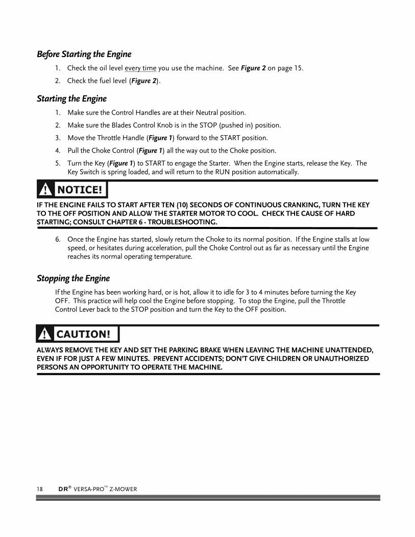
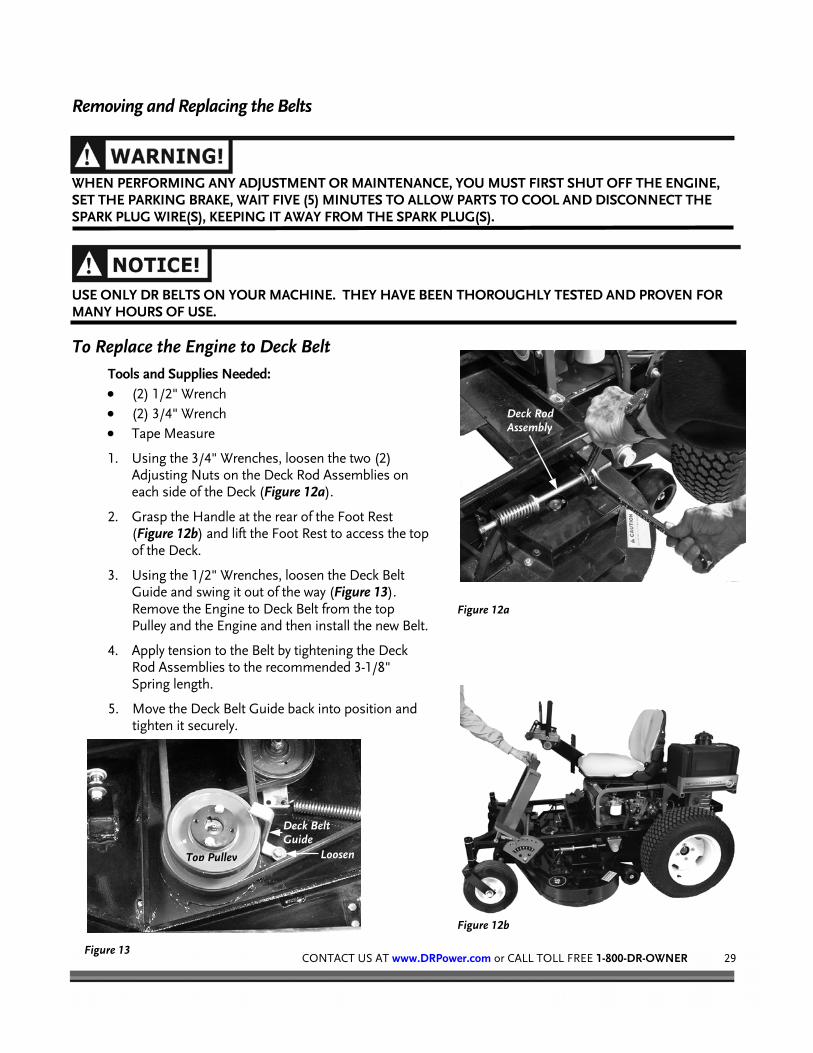
1. Using the 3/4" Wrenches, loosen the two (2) Adjusting Nuts on the Deck Rod Assemblies on each side of the Deck (Figure 12a).
2. Grasp the Handle at the rear of the Foot Rest (Figure 12b) and lift the Foot Rest to access the top of the Deck.
3. Using the 1/2" Wrenches, loosen the Deck Belt Guide and swing it out of the way (Figure 13). Remove the Engine to Deck Belt from the top Pulley and the Engine and then install the new Belt.
4. Apply tension to the Belt by tightening the Deck Rod Assemblies to the recommended 3-1/8" Spring length.
5. Move the Deck Belt Guide back into position and tighten it securely.
Figure 12a
Figure 12b
Figure 13
Deck Belt Guide
Loosen
Deck Rod Assembly
Top Pulley

30 DR® VERSA-PRO™ Z-MOWER
To Replace the Hydro Drive Belt
WHEN PERFORMING ANY ADJUSTMENT OR MAINTENANCE, YOU MUST FIRST SHUT OFF THE ENGINE, SET THE PARKING BRAKE, WAIT FIVE (5) MINUTES TO ALLOW PARTS TO COOL AND DISCONNECT THE SPARK PLUG WIRE(S), KEEPING ITHEM AWAY FROM THE SPARK PLUG(S).
USE ONLY DR BELTS ON YOUR MACHINE. THEY HAVE BEEN THOROUGHLY TESTED AND PROVEN FOR MANY HOURS OF USE.
Tools Needed:
• (2) 1/2" Wrench • (2) 3/4" Wrench • Tape Measure
1. Referring to the instructions on the previous page, remove the Engine to Deck Belt.
2. Remove the Adjusting Nut from the Eye Bolt on the Main Drive Idler Pulley (Figure 14a).
3. Disconnect the Electrical Wires from the Clutch (Figure 14b).
4. Remove the old Belt.
5. Mount the new Belt and tighten it. The Belt should have 3/4" to 1" deflection.
6. Replace the Eye Bolt and Adjusting Nut on the Main Drive Idler Pulley.
7. Replace the Clutch Bracket and re-connect the Clutch Wires.
8. Mount the Belt onto the top Pulley on the Deck.
9. Replace the Engine to Deck Belt Guide.
Figure 14a
Mule Drive Spring
Adjusting Nut
Deck Rod Assembly
Main Drive Idler Pulley
Eye Bolt
Figure 14b
Hydro Clutch Wires

CONTACT US AT www.DRPower.com or CALL TOLL FREE 1-800-DR-OWNER 31
To Replace the Deck Belt
WHEN PERFORMING ANY ADJUSTMENT OR MAINTENANCE, YOU MUST FIRST SHUT OFF THE ENGINE, SET THE PARKING BRAKE, WAIT FIVE (5) MINUTES TO ALLOW PARTS TO COOL AND DISCONNECT THE SPARK PLUG WIRE(S), KEEPING IT AWAY FROM THE SPARK PLUG(S).
USE ONLY DR BELTS ON YOUR MACHINE. THEY HAVE BEEN THOROUGHLY TESTED AND PROVEN FOR MANY HOURS OF USE.
Tools Needed:
• 7/16" Wrench • (2) 1/2" Wrench • Tape Measure
1. Remove the Belt Guards from the Deck (Figure 15).
2. Remove the Engine to Deck Belt from the top Pulley on the Deck. See Steps 1 through 3 on page 29.
3. Work the Deck Belt off the Pulleys, starting with the Pulley closest to the Discharge Chute.
4. Mount the new Belt on the Deck Pulleys.
5. Replace the Engine to Deck Belt on the top Pulley on the Deck. See Steps 3, 4, and 5 on page 29.
6. Replace the Belt Guards.
Adjusting the Engine to Deck Belt Tools Needed:
• 3/4" Wrenches
1. To adjust the Engine to Deck Drive Belt tension, loosen the two Adjusting Nuts on the Deck Rod Assemblies (Figure 11 on page 29). Turn Rear Nut clockwise to tighten the Belt. For recommended tension, compress the Drive Springs to approximately 3-1/8" on both sides of the Deck.
Adjusting the Hydro Drive Belt Tools Needed:
• 3/4" Wrenches
Turning the Adjusting Nut clockwise on the Eye Bolt will tighten the Mule Drive Spring (Figure 14a on page 30). Tighten the Adjusting Nut until the Spring has about a 1/32" to 1/16" gap between the coils of the Spring.
Figure 15
Belt Guard

32 DR® VERSA-PRO™ Z-MOWER
Removing and Replacing the Blades To obtain optimum mowing results, you should keep the mower blades sharp and well balanced. Follow the instructions below to remove, sharpen, and/or replace the blades.
WHEN PERFORMING ANY ADJUSTMENT OR MAINTENANCE, YOU MUST FIRST SHUT OFF THE ENGINE, SET THE PARKING BRAKE, WAIT FIVE (5) MINUTES TO ALLOW PARTS TO COOL AND DISCONNECT THE SPARK PLUG WIRE(S), KEEPING IT AWAY FROM THE SPARK PLUG(S).
SHARP EDGES OF BLADES CAN CUT YOU DURING BLADE MAINTENANCE OR ADJUSTMENT. USE GLOVES OR A RAG WHEN HANDLING BLADES TO PREVENT INJURIES.
Tools and Supplies Needed:
• 15/16" Wrench or Socket • (2) 1/2" Wrench • Pliers • Gloves or a Rag • Block of wood to brace the Blade
1. Remove the Deck from the chassis following the instructions on page 33. Invert the Deck as shown in Figure 16.
2. Place a short piece of 2 x 4 lumber between the side of the Deck and the Blade to “lock” it in position (Figure 16). Using a 15/16" Wrench, remove the Blade attaching Bolts and Washers from the Spindle. Remove the Blade and repeat this step for the other two (2) Blades.
3. File or grind the Blades evenly. Take care to retain the angle of the original cutting edge.
NOTE: You should always check the Blade balance. Inexpensive blade balancers are available at most hardware stores.
4. Reinstall the Blades with the Lift (turned up) portion (Figure 17) facing up. Tighten the Blade attaching Bolts securely.
NOTE: Be sure to seat the Blade completely over the small ridge in the Spindle Hub before tightening the Bolt.
5. Reinstall the Deck following the instructions on page 34.
Figure 16
Figure 17
Blade Lift Facing Up

CONTACT US AT www.DRPower.com or CALL TOLL FREE 1-800-DR-OWNER 33
Removing the Deck
WHEN PERFORMING ANY ADJUSTMENT OR MAINTENANCE, YOU MUST FIRST SHUT OFF THE ENGINE, SET THE PARKING BRAKE, WAIT FIVE (5) MINUTES TO ALLOW PARTS TO COOL AND DISCONNECT THE SPARK PLUG WIRE(S), KEEPING IT AWAY FROM THE SPARK PLUG(S).
It is very important to clean the underside of the Deck frequently. Accumulation of clippings and debris will prevent the Mower from “lifting” grass into the cutting position and discharging clippings evenly. Grass accumulating under the Deck is often a cause of uneven cutting. For best results when cleaning the Deck, remove it from the chassis and invert it.
Tools Needed: • (2) 1/2" Wrench • (2) 3/4" Wrench • (1) 9/16" Wrench • Wood for blocking
1. Raise the Deck to the Transport Position. See “Adjusting the Deck Height” on page 34.
2. Stabilize the machine on a level surface and set the Parking Brake.
3. Grasp the Handle at the rear of the Foot Rest (Figure 12 on page 29) and lift the Foot Rest to access the top of the Deck.
4. Loosen the Deck Rod Assemblies (Figure 11 on page 29) on each side of the Deck.
NOTE: The Deck Rod Assemblies will remain connected to the Deck.
5. Loosen the Deck Belt Guide (Figure 13 on page 29) and swing it aside.
6. Remove the Engine to Deck Belt from the top pulley.
7. Using a 9/16" Wrench, remove one end of the Side Motion Rod (Figure 18).
8. Place several 3"- 4" high wood blocks evenly around the perimeter of the Mower Deck and lower the Deck until it rests on the wood blocks.
9. Using 1/2" Wrenches, remove the Upper Bolts (Figure 19) from the four (4) Deck Lift Levers connecting the Chain to the Deck Brackets.
10. Using the Lifting Handles located on each side of the Deck, lift one side of the Deck and carefully remove the wood blocks. Lower the Deck until it rests on the Deck Wheels. Repeat for the other side.
Figure 18
Side Motion Rod Lifting Handle
Figure 19
Upper Deck Lift Bolt
Deck Bracket

34 DR® VERSA-PRO™ Z-MOWER
11. Push the Foot Pedal forward to lift the Deck Height Adjuster as high as possible and pin it in place with the Quick Release Pin (Figure 20).
12. Release the Parking Brake.
13. Alternately push the front of the Mower to one side and pull the Deck from beneath the chassis.
14. Reverse the above procedure to re-install the Deck.
15. Re-adjust the Engine to Deck Belt tension following the instructions on page 31.
Adjusting the Deck Height
WHEN PERFORMING ANY ADJUSTMENT OR MAINTENANCE, YOU MUST FIRST SHUT OFF THE ENGINE, SET THE PARKING BRAKE, WAIT FIVE (5) MINUTES TO ALLOW PARTS TO COOL AND DISCONNECT THE SPARK PLUG WIRE(S), KEEPING IT AWAY FROM THE SPARK PLUG(S).
The adjustment of the Deck Height is by means of a foot pedal (Figure 20) located at the left front of the machine.
1. To place the Deck in Transport Position, push the Foot Pedal all the way forward until the rear edge of the Pedal is beyond the Notch in the Rim of the Deck Adjusting Block. Tilt the rear of the Pedal downward and slowly release it until it engages the Notch.
2. Remove the Quick Release Pin and place it in the desired position.
3. Release the Foot Pedal from the Transport position by pushing it slightly forward while tilting it to lift the rear edge. Slowly allow the Pedal to move backward to the new pin location.
• ALWAYS DISENGAGE THE BLADES AND MOVE THE DECK TO THE TRANSPORT POSITION WHEN RIDING THE MACHINE FROM PLACE TO PLACE.
• NEVER ATTEMPT TO ADJUST THE DECK HEIGHT WHILE OPERATING THE MACHINE IN THE WALK-BEHIND MODE.
• ALWAYS DISENGAGE THE BLADES BEFORE CHANGING DECK HEIGHT.
Figure 20
Quick Release Pin
Foot Pedal
Transport Position Notch

CONTACT US AT www.DRPower.com or CALL TOLL FREE 1-800-DR-OWNER 35
Leveling the Deck
WHEN PERFORMING ANY ADJUSTMENT OR MAINTENANCE, YOU MUST FIRST SHUT OFF THE ENGINE, SET THE PARKING BRAKE, WAIT FIVE (5) MINUTES TO ALLOW PARTS TO COOL AND DISCONNECT THE SPARK PLUG WIRE(S), KEEPING IT AWAY FROM THE SPARK PLUG(S).
There are four (4) Adjustable Hangers (Figure 21) on the Mower Deck and used to maintain a consistent cutting height across the Deck. These may need adjustment from time to time.
NOTE: A higher Bolt position allows lower cutting heights.
Tools Needed: • (2) 1/2" Wrench • Wood Blocking
1. Raise the Deck to the Transport Position. See page 34. Place equal height Blocks beneath each corner of the Deck. Lower the Deck so that it rests on the Blocks and relieves the tension on the chain supports.
2. Re-position the Deck Bolt (Figure 21) in the slot as required by removing the Bolt, placing it in a higher or lower position, and then tighten securely.
Adjusting the Parking Brake
Tools Needed: • Needled Nosed Pliers • 7/16" Wrench
The DR VERSA-PRO Z-MOWER is equipped with Drum Parking Brakes (Figure 22). Adjust the setting of the Brake tension as follows:
1. Move the Brake Lever to the OFF position.
2. Remove the Hitch Clip and Clevis Pin from the Yoke on the Brake Arm.
3. Remove the Turnbuckle from the Brake Arm and turn it clockwise to tighten.
NOTE: Over tightening will prevent the Brake Handle from engaging.
Deck Bolt
Figure 21
Deck Bolt
Figure 22 Clevis Pin
Turnbuckle
Hitch Clip
36 DR® VERSA-PRO™ Z-MOWER
Adjusting the Control Panel
WHEN PERFORMING ANY ADJUSTMENT OR MAINTENANCE, YOU MUST FIRST SHUT OFF THE ENGINE, SET THE PARKING BRAKE, WAIT FIVE (5) MINUTES TO ALLOW PARTS TO COOL AND DISCONNECT THE SPARK PLUG WIRE(S), KEEPING IT AWAY FROM THE SPARK PLUG(S).
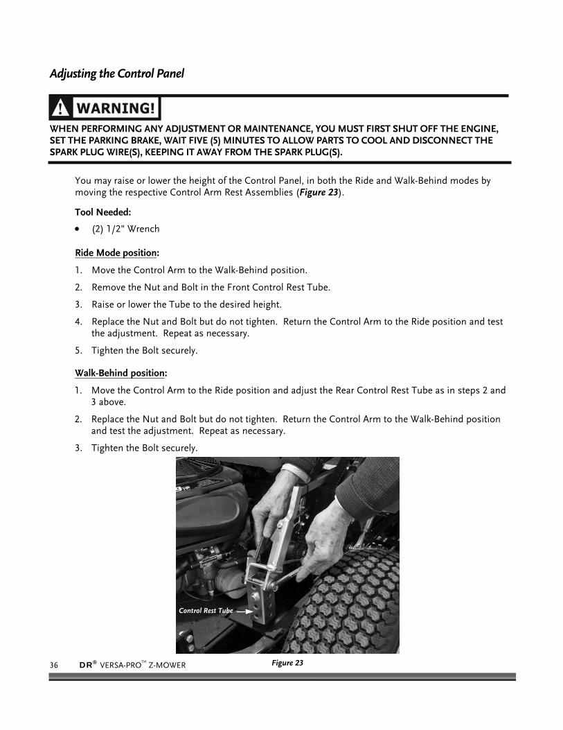
You may raise or lower the height of the Control Panel, in both the Ride and Walk-Behind modes by moving the respective Control Arm Rest Assemblies (Figure 23).
Tool Needed:
• (2) 1/2" Wrench Ride Mode position:
1. Move the Control Arm to the Walk-Behind position.
2. Remove the Nut and Bolt in the Front Control Rest Tube.
3. Raise or lower the Tube to the desired height.
4. Replace the Nut and Bolt but do not tighten. Return the Control Arm to the Ride position and test the adjustment. Repeat as necessary.
5. Tighten the Bolt securely.
Walk-Behind position:
1. Move the Control Arm to the Ride position and adjust the Rear Control Rest Tube as in steps 2 and 3 above.
2. Replace the Nut and Bolt but do not tighten. Return the Control Arm to the Walk-Behind position and test the adjustment. Repeat as necessary.
3. Tighten the Bolt securely.
Figure 23
Control Rest Tube

CONTACT US AT www.DRPower.com or CALL TOLL FREE 1-800-DR-OWNER 37
Adjusting the Hydro Tracking
WHEN PERFORMING ANY ADJUSTMENT OR MAINTENANCE, YOU MUST FIRST SHUT OFF THE ENGINE, SET THE PARKING BRAKE, WAIT FIVE (5) MINUTES TO ALLOW PARTS TO COOL AND DISCONNECT THE SPARK PLUG WIRE(S), KEEPING IT AWAY FROM THE SPARK PLUG(S).
The amount of tension on the Chain determines the amount of “play” or “slack” in the in the Control Handle travel. To insure equal response from both Control Handles, the tension on each Chain should be equal. If the machine is not tracking straight, perform the following adjustments:
DO NOT OVER TIGHTEN THE CHAIN. THIS CAN CAUSE THE CONTROL LEVERS TO JAM IN THE FORWARD OR REAR POSITION.
Tools Needed: • 1/2", 9/16", 7/16" & 3/8" Wrenches • Pliers • Masking Tape and Tape Measure
Check the Linkage Chain Tension
1. Place the Control Arm in the Walk-Behind position. Remove the Chain Guard from the Control Arm (Figure 24).
2. Viewing the Chains (Figure 25) from the Operator Position, the Left Chain controls the Right Control Handle, and the Right Chain controls the Left Control Handle. Loosening the Chain will increase the amount of slack in the Chain, tightening will decrease the amount of slack in the Chain.
3. Apply a short length of tape along the top of each Control Handle and draw a reference line for use in measuring in steps 4 and 5 below.
4. Bring the Speed Control Bar to the vertical position. Using light hand pressure, move one Control Handle forward (Figure 26) until you feel resistance. Using a tape measure, note the distance between the Speed Control Bar and Control Handle.
5. Gently move the Control Handle backward until you feel resistance again. Note the distance from the Speed Control Bar.
6. The difference in the two (2) measurements is an indication of the amount of slack in the Chain and the “Dead Zone” between Forward and Reverse.
7. Repeat Steps 3 and 4 for the other Control Handle. 8. Using a 3/8" Wrench and Pliers, loosen the Nut on the Turnbuckle for the
Control with the greatest “Dead Zone”. Adjust the Turnbuckle and re-measure until the tension is equal on both Control Handles. Re-tighten the Nut.
9. Check the full travel of each Control Handle to be certain it does not stick or jamb in any position.
10. Replace the Chain Guard and return the Control Arm to the Ride position.
Figure 24
Figure 25
Figure 26
Step 4.
Step 5.
Dead Zone

38 DR® VERSA-PRO™ Z-MOWER
Align the Control Handles
1. Position the Speed Control Bar as close to the Control Handles as possible and use it as a guide to align the Control Handles.
2. Using a 9/16" Wrench, loosen the Nuts (Figure 27) on the lower end of the Control Handles.
3. Line up the Control Handles so they are even with each other and parallel with the Speed Control Bar. Once aligned, tighten the Nuts securely.
Equalize the Wheel Speeds
The Linkage Arm (Figure 28) settings on the Left and Right Hydraulic Pumps should be the same to achieve equal speed on both Wheels. Adjust the Left Wheel speed to the Right Wheel speed as follows:
1. Remove the Left Steering Linkage Assembly by sliding the spring loaded Collar (Figure 28) away from the Joint and separating the Linkage from the Ball Pivot (Figure 29).
2. Measure the location of the Ball Pivot in the Right Hydro Control Arm.
3. Loosen the Nut holding the Left Ball Pivot to the Hydro Control Arm.
4. Slide the Ball Pivot up or down, depending upon the adjustment required to match the Right Hydro Control Arm.
NOTE: Sliding the Ball down increases the speed; sliding the ball up decreases the speed of the Wheel.
5. Replace the Linkage Arm and test the alignment. Repeat the procedure if necessary.
Figure 27 Control Handle Nuts
Figure 28
Figure 29
Collar
Ball Pivot, Up or Down
Linkage Arm Ball Pivot
Collar
Measure Ball Pivot Location in Arm Slot

CONTACT US AT www.DRPower.com or CALL TOLL FREE 1-800-DR-OWNER 39
Adjusting the Neutral Setting
• KEEP THE WORK AREA CLEAR OF CHILDREN AND PETS. • STABILIZE THE MACHINE WHILE IN THE ELEVATED POSITION DURING THIS PROCEDURE. • DISENGAGE THE BLADES AND STAND CLEAR OF THE REAR WHEELS TO AVOID CONTACT AS THEY
TURN DURING THIS PROCEDURE.
It is important to maintain proper adjustment of the Steering Linkage so that the each Handle reaches Neutral at the same position. Figure 30 shows the location of the Pump Linkage on the Hydraulic Pumps, which you can adjust to achieve the correct setting.
Tool Needed:
• 1/4" Hex Key Wrench • Lifting and Blocking Equipment
1. Block or raise the machine so that the Rear Wheels are off the ground and can rotate freely.
2. Loosen the Hex Socket Cap Screw at the bottom of the Pump Linkage on each Hydraulic Pump (Figure 30).
3. Start the Engine and run it at 3/4 Throttle setting.
4. Rotate the Pump Linkage forward and backward to find the Neutral position.
5. Once the Neutral position is determined, tighten the Cap Screw securely.
6. Repeat the procedure for the other Pump.
7. Move the Engine Throttle to Idle, turn OFF the Engine and remove the Blocking from the machine.
8. Re-start the Engine and test the setting.
Figure 30 Steering and Pump Linkage
Pump Linkage Steering Linkage
Socket Cap Screw
40 DR® VERSA-PRO™ Z-MOWER
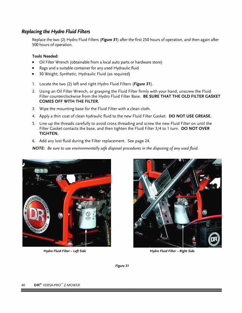
Replacing the Hydro Fluid Filters Replace the two (2) Hydro Fluid Filters (Figure 31) after the first 250 hours of operation, and then again after 500 hours of operation. Tools Needed: • Oil Filter Wrench (obtainable from a local auto parts or hardware store) • Rags and a suitable container for any used Hydraulic fluid • 30 Weight, Synthetic, Hydraulic Fluid (as required)
1. Locate the two (2) left and right Hydro Fluid Filters (Figure 31).
2. Using an Oil Filter Wrench, or grasping the Fluid Filter firmly with your hand, unscrew the Fluid Filter counterclockwise from the Hydro Fluid Filter Base. BE SURE THAT THE OLD FILTER GASKET COMES OFF WITH THE FILTER.
3. Wipe the mounting base for the Fluid Filter with a clean cloth.
4. Apply a thin coat of clean hydraulic fluid to the new Fluid Filter Gasket. DO NOT USE GREASE.
5. Line up the threads carefully to avoid cross threading and screw the new Fluid Filter on until the Filter Gasket contacts the base, and then tighten the Fluid Filter 3/4 to 1 turn. DO NOT OVER TIGHTEN.
6. Add any lost fluid during the Filter replacement. See page 24.
NOTE: Be sure to use environmentally safe disposal procedures in the disposing of any used fluid.
Hydro Fluid Filter – Left Side
Figure 31
Hydro Fluid Filter – Right Side
CONTACT US AT www.DRPower.com or CALL TOLL FREE 1-800-DR-OWNER 41
Battery Care Proper care can extend the life of a Battery. Follow these recommendations to ensure your Battery’s best performance and long life:
• Before charging the battery, observe its external appearance and keep it clean and dry. Never charge or use a Battery that shows cracks, changes shape, leaks, or otherwise obviously damaged.
• Do not allow the Battery to run down completely before charging. Leaving the Battery discharged damages the Battery. If the machine is not used, charge the Battery every 4 to 6 weeks. Operate the Engine for at least 45 minutes to maintain proper Battery charge.
• Store an unused Battery in a dry area that does not freeze.
• Do not charge an already charged Battery. In theory, you cannot overcharge our Battery with a trickle charger; however, when a Battery is fully charged and the Charger is still on, it generates heat that could be harmful to the Battery. A fully charged Battery will read 12V-13.2V with a Voltmeter.
• Do not continue to crank the Engine when the Battery charge is low. • If the battery begins to leak, avoid contact with the leaking acid. Place the damaged battery in a plastic
bag, then dispose of it properly.
IF BATTERY ACID DOES CONTACT YOUR SKIN OR EYES, FLUSH WITH COOL WATER FOR AT LEAST 15 MINUTES AND CALL A PHYSICIAN. IF YOU INGEST ACID, CALL A PHYSICIAN IMMEDIATELY.
Charging the Battery Operate the Engine for at least 45 minutes to maintain proper Battery charge. If the Battery loses its charge, you will need to use a trickle Charger (like the DR Battery Charger) to recharge it. The Charger should have an output of 12 volts at no more than 2 amps.
• At 1 amp, the Battery may need charging for as long as 48 hours.
• At 2 amps, the Battery may need charging for as long as 24 hours.
To connect a Battery charger to your DR VERSA-PRO Z-MOWER, follow the steps listed below.
1. Detach the two (2) Battery cables going to the Battery on your machine.
2. Attach the red (+) Battery Charger Wire to the red (+) Battery tab, and the black (-) Battery Charger Wire to the black (-) Battery tab.
3. Plug the Battery Charger into an outlet.
WHEN YOU ARE FINISHED CHARGING THE BATTERY, DISCONNECT THE CHARGER FROM THE OUTLET FIRST, THEN DISCONNECT THE BATTERY CHARGER WIRES FROM THE BATTERY. IF YOU LEAVE THE BATTERY CHARGER WIRES CONNECTED TO THE BATTERY, THE BATTERY WILL DISCHARGE ITSELF BACK INTO THE CHARGER.

42 DR® VERSA-PRO™ Z-MOWER
Disposing of the Battery Responsibly
The Battery is a sealed lead-acid Battery. Recycle or dispose of it in an environmentally sound way.
• Do not dispose of a lead-acid Battery in a fire; the Battery may explode or leak.
• Do not dispose of a lead-acid Battery in your regular, household trash. Law in most areas prohibits incinerating, disposing in a landfill, or mixing a sealed lead-acid Battery with household trash.
Recycling a Used Battery
PLEASE DISPOSE OF USED BATTERIES RESPONSIBLY, ACCORDING TO YOUR LOCAL HAZARDOUS MATERIALS REGULATIONS. NEVER THROW AWAY USED BATTERIES IN YOUR HOUSEHOLD TRASH.
Please dispose of your used Batteries responsibly by recycling them. Call your local Solid Waste Management District or your local waste handler to locate the collection site nearest you. Some collection sites recycle Batteries year-round; others collect them periodically.
You can also visit the Web site of Earth 911 for more information [www.earth911.org]. Once there, click the Municipal HHW link under Hazardous Household Waste, and enter your zip code. The site lists recycling centers located near you.
For a fee, you can recycle your Batteries with the International Metals Reclamation Company. Visit them at www.inmetco.com and click Services; or contact them at:
INMETCO PO Box 720 245 Portersville Road Ellwood City, PA 16117 (724) 758-2825; fax (724) 758-2845 To learn more about hazardous waste recycling, visit the Web site for Battery Council International [www.batterycouncil.org] or for the Environmental Protection Agency [www.epa.gov].

CONTACT US AT www.DRPower.com or CALL TOLL FREE 1-800-DR-OWNER 43
End of Season and Storage
If you will not use the machine for an extended period, the following steps will help insure the best performance when you return it to service:
WHEN PERFORMING ANY ADJUSTMENT OR MAINTENANCE, YOU MUST FIRST SHUT OFF THE ENGINE, SET THE PARKING BRAKE, WAIT FIVE (5) MINUTES TO ALLOW PARTS TO COOL AND DISCONNECT THE SPARK PLUG WIRE(S), KEEPING IT AWAY FROM THE SPARK PLUG(S).
NOTE: Please refer to the Engine Owner's Manual for Engine-specific procedures.
• Start the Engine and engage the Blades for approximately 1 minute to remove excess water from the Belts and Pulleys.
• Perform all required maintenance steps in the Maintenance Check List. See page 25.
• After 30 days, you should wax painted surfaces to protect the luster of the original finish. Wash the machine regularly with a mild automotive type detergent and water. Coat exposed bare metal surfaces with oil, or a light coating of grease to prevent rust, until you make permanent repairs.
• Change the oil and oil filter.
• Remove the Spark Plug(s) and pour about 1 ounce of motor oil into the Cylinder hole(s). Replace the Plug(s) and crank the Engine for a couple of seconds. This will coat the piston(s) and seat the valves to prevent moisture buildup.
• Clean/replace the Air Filter(s).
• Clean dirt and debris from the Cylinder Head Cooling Fins, Blower Housing, Debris Screen, and Muffler area of the Engine.
• If your Engine has a Fuel Filter, replace it.
• If your DR VERSA-PRO Z-MOWER will be idle for more than 30 days, we recommend using a gas stabilizer. This will prevent sediment from gumming up the Carburetor. If there is dirt or moisture in the gas or tank, remove it by draining the tank. Completely fill the tank with fresh, unleaded gas and add the appropriate amount of stabilizer or gasoline additive. Run the Engine for a short time to allow the additive to circulate.
• Remove any wrapped weeds from the Blade Bearing Housings. Clean grass and debris from the top and underneath the Mower Deck with a stiff brush.
• Check the Blades for nicks and wear. Remove the Blades and sharpen, or have them professionally sharpened if needed.
• You should remove the Battery and keep it in a cool, dry place when the DR VERSA-PRO Z-MOWER is in storage. We suggest charging the Battery once a month while the DR is stored and again when you are ready to start the new season. This will help the Battery maintain its charge all season. See page 41.

44 DR® VERSA-PRO™ Z-MOWER

CONTACT US AT www.DRPower.com or CALL TOLL FREE 1-800-DR-OWNER 45
CHAPTER 6 TROUBLESHOOTING
Most problems are easy to fix. Consult the Troubleshooting Table below for common problems and their solutions. If you continue to experience problems call Country Home Products, Inc. for support.
Troubleshooting Table
WHEN PERFORMING ANY ADJUSTMENT OR MAINTENANCE, YOU MUST FIRST SHUT OFF THE ENGINE, SET THE PARKING BRAKE, WAIT FIVE (5) MINUTES TO ALLOW PARTS TO COOL AND DISCONNECT THE SPARK PLUG WIRE(S), KEEPING IT AWAY FROM THE SPARK PLUG(S).
SYMPTOM POSSIBLE CAUSE The Engine will not start.
(Please refer to the Engine Owner’s Manual for Engine-specific procedures.)
⇒ Check all the items under the section called Starting the Engine on page 18.
⇒ Check that the Control Handles are in the Neutral position.
⇒ Make sure the Spark Plug Wire(s) is attached.
⇒ Make sure the Throttle is in the Start position and the Choke is pulled out.
⇒ Check the oil and gas level. See page 15.
⇒ The gas may be old, change it. Use a fuel stabilizer if you keep gas longer than one month.
⇒ The Spark Plug(s) may be dirty or cracked, change it. If it is oily, leave it out, hold a rag over the Plug Hole(s) and crank the Engine several times to blow out any oil in the cylinder(s), then wipe off the Plug(s) and reinsert it.
⇒ Check the Fuel Filter, it may be clogged. Replace if necessary.
⇒ The Air Filter may be dirty, change it following the procedure in the Engine Owner’s Manual.
⇒ Check the wire connections—especially the ground connection, the large black wire coming from the Battery, where it connects to the Engine.
⇒ Check the wire connections to the solenoid. Disconnect the black Battery ground wire first to avoid sparks. Check to be sure that all of the connections are clean and tight. Reconnect the Battery ground wire.
⇒ Check the ground connection on the Solenoid where it bolts to the Frame. Using a wrench or socket, tighten the Bolts to ensure a good connection to the Frame.
⇒ The Battery may not be charged. Check the voltage yourself or at a service station. If it is low, charge it with a 12-volt, 1 to 2 amp trickle Charger. If you do not use your machine for at least 45 minutes at a time, the Battery may need to be periodically charged. See the Battery care section on page 41.
⇒ If the Battery is charged and the Engine still will not start, visit our website at www.DRPower.com or call 1-800-DR-OWNER (376-9637) for assistance.

46 DR® VERSA-PRO™ Z-MOWER
WHEN PERFORMING ANY ADJUSTMENT OR MAINTENANCE, YOU MUST FIRST SHUT OFF THE ENGINE, SET THE PARKING BRAKE, WAIT FIVE (5) MINUTES TO ALLOW PARTS TO COOL AND DISCONNECT THE SPARK PLUG WIRE(S), KEEPING IT AWAY FROM THE SPARK PLUG(S).
SYMPTOM POSSIBLE CAUSE The Engine lacks power or is not running smoothly.
(Please refer to the Engine Owner’s Manual for Engine-specific procedures.)
⇒ Check the Throttle Lever travel and adjustment. Make sure the Throttle Lever is in the Run position.
⇒ Check that the Air Filter is clean. If it is dirty, change it following the procedure in the Engine Owner’s Manual.
⇒ The Spark Plug(s) may be dirty or cracked, change it. If it is oily, leave it out, hold a rag over the Plug Hole(s) and crank the Engine several times to blow out any oil in the cylinder(s), then wipe off the Plug(s) and reinsert it.
⇒ The gas must be fresh and clean. If it is old, change it. Use a fuel stabilizer if you keep gas longer than four weeks or so.
⇒ Check the Fuel Filter, it may be clogged. Replace if necessary.
⇒ Check to make sure that your Engine has the right amount of clean oil. If it is dirty, change it following the procedure on page 28.
⇒ If your Engine still lacks power, visit our website at www.DRPower.com or call 1-800-DR-OWNER (376-9637) for assistance.
Engine smokes. ⇒ Check the oil level and adjust as needed.
⇒ You may be operating the machine on too great an incline. See Slopes on page 22.
⇒ Check the Air Filter(s) and clean or replace if needed.
⇒ You may be using the wrong oil—too light for the temperature. Refer to your Engine Owner’s Manual for detailed information.
⇒ Clean the Cooling Fins if they are dirty.
⇒ If the Engine still smokes, visit our website at www.DRPower.com or call 1-800-DR-OWNER (376-9637) for assistance.
Engine runs fine but the machine will not move.
⇒ The Drive Belt is broken or out of adjustment. See pages 30 and 31.
⇒ The Transmission may be defective, visit our website at www.DRPower.com or call 1-800-DR-OWNER (376-9637) for assistance.
A Belt frays or rolls over its Pulley.
⇒ A Pulley groove may be nicked. Check the Belt for wear and hard spots. File off any nicks on the Pulley.
⇒ The Belt may be stretched; replace it.

CONTACT US AT www.DRPower.com or CALL TOLL FREE 1-800-DR-OWNER 47
WHEN PERFORMING ANY ADJUSTMENT OR MAINTENANCE, YOU MUST FIRST SHUT OFF THE ENGINE, SET THE PARKING BRAKE, WAIT FIVE (5) MINUTES TO ALLOW PARTS TO COOL AND DISCONNECT THE SPARK PLUG WIRE(S), KEEPING IT AWAY FROM THE SPARK PLUG(S).
SYMPTOM POSSIBLE CAUSE The Mower Blades will not engage.
⇒ You are not holding the Operator Presence Lever against the Handle. ⇒ The Engine to Deck Belt is broken or out of adjustment. See pages 29 and 31. ⇒ The Clutch wires are broken or disconnected. Re-connect the wires or call 1-800-
DR-OWNER (376-9637) for assistance. ⇒ The Clutch is defective. Call 1-800-DR-OWNER (376-9637) for assistance.
The Blade Deck vibrates when engaged.
⇒ A Blade may not be seated properly on its Hub. Loosen the Blade Bolt, reseat the Blade, and tighten the Bolt. Be sure to turn OFF the Engine and remove the Spark Plug Wire(s) before performing this operation.
⇒ Replace a Blade if it is chipped, bent, or broken.
⇒ A Spindle Bearing may be bad or a Spindle Shaft is bent. Call 1-800-DR-OWNER (376-9637) for assistance.
A Blade is not cutting or is loose.
⇒ The Blade may not be seated properly on the hub. Loosen the Blade Bolt, reseat the Blade, and tighten the Bolt. Be sure to turn OFF the Engine and remove the Spark Plug Wire(s) before performing this operation.
⇒ Sharpen the Blade; it may be dull or nicked.
The machine will not track straight, wheels pulling left or right.
⇒ Check the Tire pressure. There should be 10 psi in each Tire.
⇒ The Hydro Tracking might be out of adjustment. See page 37.
The Mower “creeps” with the Control Handles at rest.
⇒ The Neutral Setting is out of adjustment. See page 39.
The Mower is not cutting evenly.
⇒ The Deck is not level. See page 35.
⇒ The Mower ground speed is too fast. Reduce the speed. See Tips on page 21.
⇒ The Mower Deck is clogged. Shut the Engine OFF, remove the Spark Plug Wire(s), and clean the underside of the Deck.
⇒ The Tire pressures are incorrect. There should be 10 psi in all Tires.

48 DR® VERSA-PRO™ Z-MOWER
CHAPTER 7 PARTS LISTS, SCHEMATIC DIAGRAMS AND WARRANTY
Parts List - Engine to Chassis NOTE: Part numbers listed are available through DR Power Equipment.
Ref# Part# Description
01 225201 19.5 HP Briggs & Stratton Engine 225211 22 HP Briggs & Stratton Engine
02 241131 Frame
03 225431 Tie Rod Assembly
04 104831 Battery
05 241161 Battery, Strap
06 241181 Battery Cable, Red
07 241191 Battery Cable, Black
08 241171 Bumper, Battery Stop
09 227831 Bolt, 5/16"-18 x 2" HCS
10 227961 Washer, Flat, 5/16"
11 226591 Wire Assembly, Ground, Clutch
12 228001 Washer, Lock, Split, 5/16"
13 227911 Nut, Nylock, 5/16"-18
14 227971 Washer, Flat, 3/8"
15 227951 Nut, Nylock, 3/8"-24
16 226601 Tool Tray
17 227801 Bolt, 5/16"-18 x 3/4" HCS
18 241341 Nut, Lock, 5/16"-18
19 225231 Rod, Tie, End
20 228011 Washer, Split, 3/8"
21 228081 Nut, Hex, 3/8"-24
22 225441 Rod, Tie, All Thread
23 226551 Tube, Tie Rod, Short

CONTACT US AT www.DRPower.com or CALL TOLL FREE 1-800-DR-OWNER 49
Schematic - Engine to Chassis
080210

50 DR® VERSA-PRO™ Z-MOWER
Parts List - Chassis Foot Lift Assembly NOTE: Part numbers listed are available through DR Power Equipment.
Ref# Part# Description
01 227701 Pivot Shaft w/Key
02 227681 Shaft, Deck
03 227641 Chassis Bracket w/No Holes
04 227651 Chassis Bracket w/Holes
05 227631 Block, Adjusting, Deck
06 227661 Arm, Foot Pedal
07 227671 Foot Pedal Assembly
08 227711 Spacer, Adjusting Block
09 167810 Collar, Caster
10 226531 Lever, Deck Lift, L/Hand
11 226521 Lever, Deck Lift, R/Hand
12 228261 Bolt, Carriage, 5/16"-18 x 1"
13 228331 Screw, Set, Square Head, 5/16"-18 x 1/2"
14 184190 Spring, Linkage
15 227811 Bolt, 5/16"-18 x 1" HCS
16 227801 Bolt, 5/16"-18 x 3/4" HCS
17 227911 Nut, Nylock, 5/16"-18
18 228001 Washer, Split, 5/16"
19 228041 Nut, Hex, 5/16"-18
20 226121 Non Slip Foot Pad
21 228221 Fitting, Pipe, Grease, 1/8"
22 167820 Bushing, Caster, Nylon
23 228151 Key Stock, 1/4" x 3/4"

CONTACT US AT www.DRPower.com or CALL TOLL FREE 1-800-DR-OWNER 51
Schematic - Chassis Foot Lift Assembly
080210
Chassis Bracket Assembly

52 DR® VERSA-PRO™ Z-MOWER
Parts List - Lower Chassis Assembly NOTE: Part numbers listed are available through DR Power Equipment.
Ref# Part# Description
01 228371 Hydro Belt
02 159220 Clutch for 1" Engine Shaft
03 202071 Pulley, Engine Drive, 1"
04 202081 Pulley, Hydro Drive
05 159620 Bushing, Hydro Pulley
06 227501 Bracket, Clutch
07 161900 Washer, Lock, Split, 1/4"
08 227781 Bolt, 1/4"-20 x 1" HCS
09 227961 Washer, Flat, 5/16"
10 227911 Nut, Nylock, 5/16"-18
11 228131 Bolt, 7/16"-20 x 3" Fine Thread
12 228021 Washer, Split, 7/16"
13 168411 Spacer, Engine Shaft, 1" ID
14 228151 Key Stock, 1/4" x 3/4"
16 228141 Key Stock, 3/16" x 1"
17 227831 Bolt, 5/16"-18 x 2" HCS
18 202061 Pulley, Idler, Deck
19 227981 Washer, Flat, 1/2"
20 176261 Spring, Mule Drive
21 167270 Bolt, Eye, 5/16"-18 x 3-1/2" 22 225261 Bushing, 1" ID, Bronze 23 226051 Fitting, Grease, 5/16", Drive
24 225421 Pin, Cotter
25 226631 Idler Assembly
26 227931 Nut, Nylock, 1/2"-13

CONTACT US AT www.DRPower.com or CALL TOLL FREE 1-800-DR-OWNER 53
Schematic - Lower Chassis Assembly
070110

54 DR® VERSA-PRO™ Z-MOWER
Parts List - Deck Lift Arm Assembly NOTE: Part numbers listed are available through DR Power Equipment.
Ref# Part# Description
01 227701 Pivot Shaft w/Key
02 227691 Shaft, Deck
03 226471 Arm, Lift, Deck
04 226521 Lever, Deck Lift, R/Hand
05 226531 Lever, Deck Lift, L/Hand
06 227761 Chain, Deck Lift
07 167810 Collar, Caster
08 227821 Bolt, 5/16"-18 x 1-1/4" HCS
09 227811 Bolt, 5/16"-18 x 1" HCS
10 227961 Washer, Flat, 5/16"
11 227911 Nut, Nylock, 5/16"-18
12 226341 Bolt, 5/16"-18 x 1-1/4" HCS, Gr 8
13 228041 Nut, Hex, 5/16"-18

CONTACT US AT www.DRPower.com or CALL TOLL FREE 1-800-DR-OWNER 55
Schematic - Deck Lift Arm Assembly
080210

56 DR® VERSA-PRO™ Z-MOWER
Parts List - Deck to Chassis Assembly NOTE: Part numbers listed are available through DR Power Equipment.
Ref# Part# Description
01 185631 Deck Spring Assembly
02 225371 Side Motion Rod Assembly
03 226341 Bolt, 5/16"-18 x 1-1/4" HCS, Gr 8
04 228041 Nut, Hex, 5/16"-18
05 227961 Washer, Flat, 5/16"
06 227911 Nut, Nylock, 5/16"-18
07 227971 Washer, Flat, 3/8"
08 227951 Nut, Nylock, 3/8"-24
09 228351 Nut, Cap, Push, Deck Rod
10 225231 Rod, Tie, End
11 228011 Washer, Split, 3/8"
12 228081 Nut, Hex, 3/8"- 24
13 226321 Rod, Motion, Deck Side
14 228061 Nut, Hex, 1/2"-13
15 228031 Washer, Split, 1/2"
16 226611 Washer, Adjusting Rod, Deck
17 225411 Spring, Drive, Deck
18 228351 Cap, Push, Deck Rod

CONTACT US AT www.DRPower.com or CALL TOLL FREE 1-800-DR-OWNER 57
Schematic - Deck to Chassis Assembly
080210

58 DR® VERSA-PRO™ Z-MOWER
Parts List - Deck 48" NOTE: Part numbers listed are available through DR Power Equipment.
Ref# Part# Description
01 227741 Deck Shell, 48"
02 228411 Deflector, Discharge
03 225171 Guard, Belt, 48", LH
04 155440 Belt, Deck
05 228581 Belt, Engine to Deck, 48"
06 226481 Bracket, Deck, Front, R/H
07 226491 Bracket, Deck, Front, L/H
08 209011 Pulley, Top, 48"
09 228021 Washer, Split, 7/16"
10 227761 Chain, Deck Lift
11 222861 Wheel, Anti Scalp, 5/8" Hole
12 222871 Wheel, Anti Scalp, 1/2" Hole
13 226631 Idler Assembly
14 202181 Spring, Deck
15 202061 Pulley, Idler, Deck
16 225261 Bushing, 1" ID, Bronze
17 225121 Extension, Flag Spring
18 156770 Spindle, Outside, 2"
19 159870 Spindle, Center, 3"
20 152871 Blade, for 48" Deck
21 202081 Pulley, Spindle
22 166041 Guide, Belt, Deck
23 225451 Bushing, Taper Pulley
24 228311 Key Stock, 1/4" x 2-1/2"
25 228161 Key Stock, 1/4" x 1-1/2"
26 225421 Pin, Cotter
27 228111 Bushing, Machine, 1" ID, 18 Ga.
28 167830 Bushing, Machine, 1" ID, 14 Ga.
29 226051 Fitting, Grease, Drive, 5/16"
30 228191 Bolt, 1/2"-13 x 2-1/4" HCS
31 227841 Bolt, 3/8"-16 x 1-1/4" HCS
32 226041 Bolt, Blade
33 227851 Bolt, 3/8"-16 x 1-1/2" HCS
34 227821 Bolt, 5/16"-18 x 1-1/4" HCS
Ref# Part# Description
35 222851 Bolt, 1/2"-13 x 7" HCS
36 223071 Bolt, Anti Scalp, 3/8" x 3-3/4"
37 222881 Bushing, Anti Scalp, Wheel
38 226341 Bolt, 5/16"-18 x 1-1/4" HCS, Gr 8
39 227781 Bolt, 1/4"-20 x 1" HCS
40 161920 Bolt, 1/4"-20 x 3/4" HCS
41 227971 Washer, Flat, 3/8"
42 227961 Washer, Flat, 5/16"
43 227981 Washer, Flat, 1/2"
44 161910 Washer, Flat, 1/4"
45 228011 Washer, Split, 3/8"
46 161900 Washer, Split, 1/4"
47 228051 Nut, Hex, 3/8"
48 227921 Nut, Nylock, 3/8"-16
49 227911 Nut, Nylock, 5/16"-18
50 228041 Nut, Hex, 5/16"-18
51 227901 Nut, Nylock, 1/4"-20
52 227931 Nut, Nylock, 1/2"-13
53 228001 Washer, Split, 5/16"
54 226021 Spacer, Blade, 5/8"
55 228571 Guard, Belt, 48", RH

CONTACT US AT www.DRPower.com or CALL TOLL FREE 1-800-DR-OWNER 59
Schematic - Deck 48"
080210

60 DR® VERSA-PRO™ Z-MOWER
Parts List - Deck 52" NOTE: Part numbers listed are available through DR Power Equipment.
Ref# Part# Description
01 227751 Deck Shell, 52"
02 158311 Deflector, Discharge
03 227531 Guard, Belt, 52", LH
04 225321 Belt, Deck
05 225331 Belt, Engine to Deck, 52"
06 226481 Bracket, Deck, Front, R/H
07 226491 Bracket, Deck, Front, L/H
08 226511 Deck Bracket Rear L/H
09 226501 Deck Bracket Rear R/H
10 227761 Chain, Deck Lift
11 222861 Wheel, Anti Scalp, 5/8" Hole
12 222871 Wheel, Anti Scalp, 1/2" Hole
13 226631 Idler Assembly
14 202181 Spring, Deck
15 202061 Pulley, Idler, Deck
16 225261 Bushing, 1" ID, Bronze
17 225121 Extension, Flag Spring
18 156770 Spindle, Outside, 2"
19 159870 Spindle, Center, 3"
20 225381 Blade, for 52" Deck
21 202081 Pulley, Spindle
22 166041 Guide, Belt, Deck
23 225451 Bushing, Taper Pulley
24 228311 Key Stock, 1/4" x 2-1/2"
25 228161 Key Stock, 1/4" x 1-1/2"
26 225421 Pin, Cotter
27 228111 Bushing, Machine, 1" ID, 18 Ga.
28 167830 Bushing, Machine, 1" ID, 14 Ga.
29 226051 Fitting, Grease, Drive, 5/16"
30 228191 Bolt, 1/2"-13 x 2-1/4" HCS
31 227841 Bolt, 3/8"-16 x 1-1/4" HCS
32 226041 Bolt, Blade
33 227851 Bolt, 3/8"-16 x 1-1/2" HCS
34 227821 Bolt, 5/16"-18 x 1-1/4" HCS
Ref# Part# Description
35 222851 Bolt, 1/2"-13 x 7" HCS
36 223071 Bolt, Anti Scalp, 3/8"-16 x 3-3/4"
37 222881 Bushing, Anti Scalp, Wheel
38 226341 Bolt, 5/16"-18 x 1-1/4" HCS, Gr 8
39 227781 Bolt, 1/4"-20 x 1" HCS
40 161920 Bolt, 1/4"-20 x 3/4" HCS
41 227971 Washer, Flat, 3/8"
42 227961 Washer, Flat, 5/16"
43 227981 Washer, Flat, 1/2"
44 161910 Washer, Flat, 1/4"
45 228011 Washer, Split, 3/8"
46 161900 Washer, Split, 1/4"
47 228051 Nut, Hex, 3/8"-16
48 227921 Nut, Nylock, 3/8"-16
49 227911 Nut, Nylock, 5/16"-18
50 228041 Nut, Hex, 5/16"-18
51 227901 Nut, Nylock, 1/4"-20
52 227931 Nut, Nylock, 1/2"-13
53 228001 Washer, Split, 5/16"
54 226021 Spacer, Blade, 5/8"
55 228021 Washer, Split, 7/16"
56 227521 Guard, Belt, 52", RH
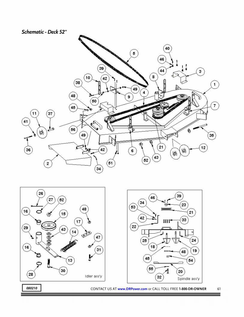
CONTACT US AT www.DRPower.com or CALL TOLL FREE 1-800-DR-OWNER 61
Schematic - Deck 52"
080210

62 DR® VERSA-PRO™ Z-MOWER
Parts List - Seat Pedestal Assembly NOTE: Part numbers listed are available through DR Power Equipment.
Ref# Part# Description
01 227731 Rest, Foot
02 226391 Pedestal, Seat
03 159191 Tank, Gas, 5 Gallon
04 165791 Cap, Gas
05 225131 Strap, Gas Tank
06 228721 Cable, Choke
07 225461 Rod, Foot Rest, All Thread
08 226011 Rod, Seat Plate, All Thread
09 225151 Ring, Gas Tank
10 225141 Bracket, Gas Tank Valve
11 228321 Rivet, 3/16"
12 226411 Plate, Seat
13 227971 Washer, Flat, 3/8"
14 227921 Nut, Nylock, 3/8"-16
15 227821 Bolt, 5/16"-18 x 1-1/4" HCS
16 228001 Washer, Split, 5/16"
17 227961 Washer, Flat, 5/16"
18 227611 Seat, Fold Down, Gray
19 226411 Plate, Seat
20 227621 Suspension (Optional Equipment)
21 227801 Bolt, 5/16"-18 x 3/4" HCS
22 227911 Nut, Nylock, 5/16"-18

CONTACT US AT www.DRPower.com or CALL TOLL FREE 1-800-DR-OWNER 63
Schematic - Seat Pedestal Assembly
080125 080210

64 DR® VERSA-PRO™ Z-MOWER
Parts List - Arm Rest Assembly w/Rear Guards NOTE: Part numbers listed are available through Country Home Products, Inc.
Ref# Part# Description
01 241131 Frame
02 228611 Rear Mower Guard for 22 HP Briggs & Stratton Engine
03 226621 Rear Mower Guard for 19.5 HP Briggs & Stratton Engine
04 241151 Guard, Rear
05 228271 Bolt, 3/8"-18 x 3/4" HCS
06 228291 Bolt, 3/8"-18 x 1" HCS
07 241141 Guard, Debris
08 227801 Bolt, 5/16"-18 x 3/4" HCS
09 227911 Nut, Nylon Lock, 5/16"-18
10 227961 Washer, Flat, 5/16"
11 228241 Nut, Lock, Wiz, 3/8"
12 227601 Latch, Control Arm
13 158430 Housing, Control Arm Latch
14 225191 Tube, Control Rest
15 227511 Spring, Lock Out
16 228301 Bolt, 1/4"-20 x 1-3/4" HCS
17 227921 Nut, Nylock, 3/8"-16
18 227901 Nut, Nylock, 1/4"-20
19 227971 Washer, Flat, 3/8"
20 227861 Bolt, 3/8"-18 x 3" HCS
21 241241 Switch w/Leads and Boot

CONTACT US AT www.DRPower.com or CALL TOLL FREE 1-800-DR-OWNER 65
Schematic - Arm Rest Assembly w/Rear Guards
080210

66 DR® VERSA-PRO™ Z-MOWER
Parts List - Control Panel Assembly NOTE: Part numbers listed are available through DR Power Equipment.
Ref# Part# Description
01 241201 Control Panel W/Console
02 159180 Speed Bar Assembly
03 209071 Knob, Speed Control
04 225181 Plate, Slide, Speed Control
05 165191 Switch, Ignition
06 157201 Key, Ignition Switch
07 241211 Switch, Blade Engage
08 156251 Hour Meter w/Bezel
09 241311 Decal, Caution, Control Panel
10 228731 Decal, Control Panel
11 161910 Washer, Flat, 1/4"
12 228091 Screw, Cap, 1/4"-20 x 3/4"
13 227961 Washer, Flat, 5/16"
14 227811 Bolt, 5/16"-18 x 1" HCS
15 227911 Nut, Nylock, 5/16"-18
Not Illustrated
241301 Wire Harness w/OPC
225081 Decal, Control Arm

CONTACT US AT www.DRPower.com or CALL TOLL FREE 1-800-DR-OWNER 67
Schematic - Control Panel Assembly
080210

68 DR® VERSA-PRO™ Z-MOWER
Parts List - Parking Brake Assembly NOTE: Part numbers listed are available through Country Home Products, Inc.
Ref# Part# Description
01 241131 Frame
02 226441 Crossflag Assembly
03 226431 Plate, Brake
04 226421 Brake Rod Assembly
05 226191 Rod, Push, Brake
06 226461 Plate, Handle, Brake
07 226451 Handle, Brake, Drum Brakes
08 158520 Grip, Throttle/Brake
09 226201 Link, Brake
10 226281 Pin, Clevis 1/4" x 3/4"
11 226291 Clip, Hitch # 2
12 226211 Yoke, Brake
13 228331 Screw, Set, Square Head, 5/16"-18 x 1/2"
14 227821 Bolt, 5/16"-18 x 1-1/4" HCS
15 228241 Nut, Wiz Lock, 3/8"
16 228281 Bolt, 3/8"-18 x 1" HCS
17 227921 Nut, Nylock, 3/8"
18 227971 Washer, Flat, 3/8"
19 228201 Screw, Cap, 1/4"-20 x 1"
20 161910 Washer, Flat, 1/4"
21 227901 Nut, Nylock 1/4"

CONTACT US AT www.DRPower.com or CALL TOLL FREE 1-800-DR-OWNER 69
Schematic - Parking Brake Assembly
070110

70 DR® VERSA-PRO™ Z-MOWER
Parts List - Control Arm Assembly NOTE: Part numbers listed are available through DR Power Equipment.
Ref# Part# Description
01 227901 Nut, Nylock, 1/4"-20
02 228231 Washer, Plastic, 1/4"
03 227551 Handle, Throttle
04 227791 Bolt, 1/4"-20 x 1-1/2" HCS
05 227771 Spacer, 1/4" ID
06 227561 Mount, Throttle Cable
07 228211 Fitting, Pipe, Straight, 1/8"
08 226371 Control Arm Assembly
09 208991 Bracket, Control Shield End
10 228111 Bushing, Machine, 1" ID, 18 Gauge
11 199131 Upper Concentric Assembly
12 225251 Bearing, Control Head
13 226111 Block, Concentric Pillow
14 226381 Shield, Control Arm
15 225301 Chain, 69"
16 225241 Bearing, Main Arm Pivot
17 199141 Lower Concentric Assembly
18 158520 Grip, Throttle/Brake
19 241261 Handle, Control, Right
20 158621 Handle, Control, Left
21 200661 Turnbuckle
22 226101 Swivel, Throttle Wire
23 226581 Spacer, Pillow Block
24 226561 Clamp, Small
25 226571 Clamp, Large
26 226351 Guard, Chain, Ride Mode, LH
27 226361 Guard, Chain, Walk Mode, RH
28 227891 Clamp, Throttle Cable
29 227871 Screw, Truss, 1/4" x 1/2"
30 228221 Grease Fitting, 1/8"-90° Pipe
31 235141 Lever, Operator Presence
32 241231 Spring, OPC Lever
33 241241 Switch w/Leads and Boot
34 241221 Pin, Spring, 3/16" x 1"
35 225261 Bushing, Bronze, 1" ID
Ref# Part# Description
36 225281 Bearing, Needle, 1" ID
37 228121 Bushing, Machine, 1-1/2" ID,18 Ga.
38 225291 Bearing, Needle, 1-1/2" ID
39 226051 Fitting, Grease, Drive, 5/16"
40 225271 Bushing, Bronze, 1-1/2" ID
41 228181 Ring, Snap, 1-1/2"
42 227541 Tube, Lower, Inner
43 227581 Tube, Upper/Lower, Outer
44 227571 Tube, Upper, Inner

CONTACT US AT www.DRPower.com or CALL TOLL FREE 1-800-DR-OWNER 71
Schematic - Control Arm Assembly
080211

72 DR® VERSA-PRO™ Z-MOWER
Parts List - Wheel Drive Assembly NOTE: Part numbers listed are available through DR Power Equipment.
Ref# Part# Description
01 241131 Frame
02 210701 Motor, Wheel
03 228381 Pump, Right Hand
04 228391 Pump, Left Hand
05 225161 Linkage, Pump
06 184200 Steering Linkage Assembly
07 226141 Fitting, 90 Degree, BDP
08 203981 Fitting, Push On, Hydro
09 226131 Fitting, Pump, 90 Degree
10 203951 Fitting, Filter, 90°
11 226331 Fitting, Straight, Wheel Motor
12 227911 Nut, Nylock, 5/16"-18
13 161910 Washer, Flat, 1/4"
14 228001 Washer, Split, 5/16"
15 228071 Nut, Hex, 5/16"-24
16 227801 Bolt, 5/16"-18 x 3/4" HCS
17 227921 Nut, Nylock, 3/8"-16
18 227971 Washer, Flat, 3/8"
19 227931 Nut, Nylock, 1/2"-13
Ref# Part# Description
20 228341 Bolt, 1/2"-13 x 3" HCS
21 227841 Bolt, 3/8"-16 x 1-1/4" HCS
22 226221 High Pressure Line
23 241291 Nut, Jam, 1/4"-20
24 161920 Bolt, 1/4"-20 x 3/4" HCS
25 241251 Switch w/Leads and Boot
26 226061 Rod, Steering Linkage
27 225221 Joint, Ball, Steering
28 217281 Rear Wheel & Tire, 23" x 8.5" x 12" (19.5 HP) 226081 Rear Wheel & Tire, 23" x 10.5" x 12"
(22 HP)
29 210731 Spacer, Wheel Motor
30 226261 Pin, Cotter
31 226301 Nut, Wheel Motor
32 210711 Brake, Drum
33 226311 Key, Woodruff
34 158271 Nut, Lug
35 210721 Drum, Wheel Motor

CONTACT US AT www.DRPower.com or CALL TOLL FREE 1-800-DR-OWNER 73
Schematic - Wheel Drive Assembly
080211
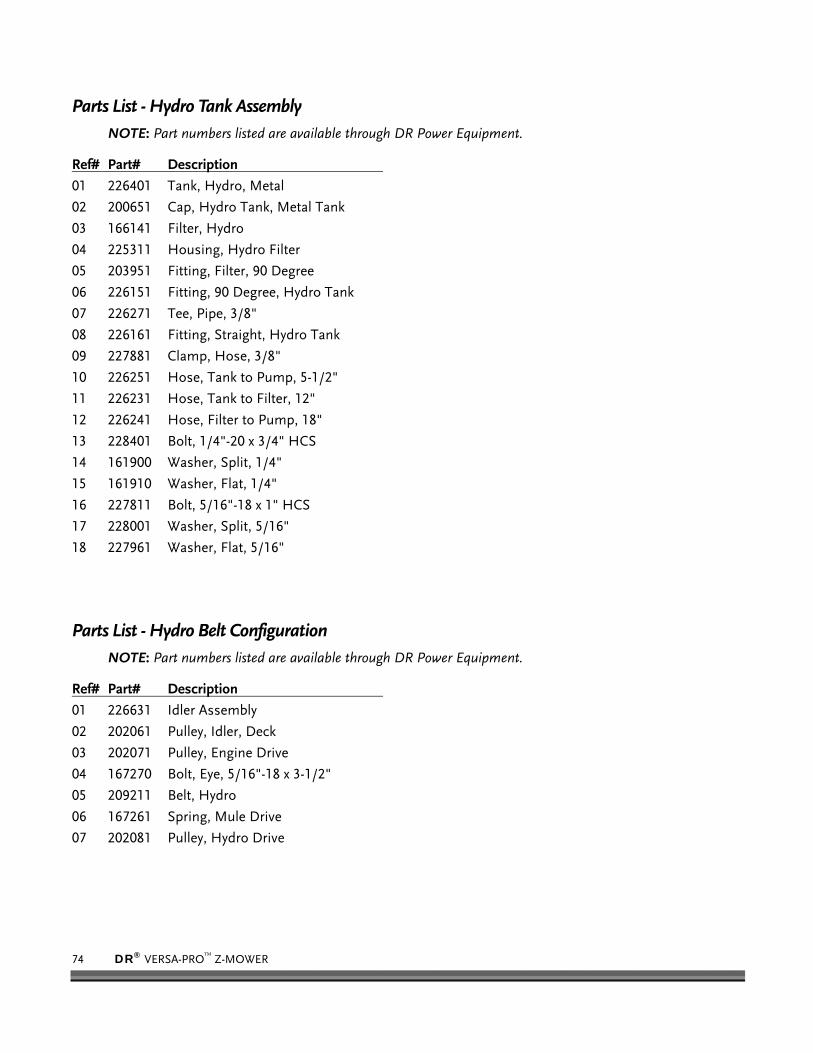
74 DR® VERSA-PRO™ Z-MOWER
Parts List - Hydro Tank Assembly NOTE: Part numbers listed are available through DR Power Equipment.
Ref# Part# Description
01 226401 Tank, Hydro, Metal
02 200651 Cap, Hydro Tank, Metal Tank
03 166141 Filter, Hydro
04 225311 Housing, Hydro Filter
05 203951 Fitting, Filter, 90 Degree
06 226151 Fitting, 90 Degree, Hydro Tank
07 226271 Tee, Pipe, 3/8"
08 226161 Fitting, Straight, Hydro Tank
09 227881 Clamp, Hose, 3/8"
10 226251 Hose, Tank to Pump, 5-1/2"
11 226231 Hose, Tank to Filter, 12"
12 226241 Hose, Filter to Pump, 18"
13 228401 Bolt, 1/4"-20 x 3/4" HCS
14 161900 Washer, Split, 1/4"
15 161910 Washer, Flat, 1/4"
16 227811 Bolt, 5/16"-18 x 1" HCS
17 228001 Washer, Split, 5/16"
18 227961 Washer, Flat, 5/16"
Parts List - Hydro Belt Configuration
NOTE: Part numbers listed are available through DR Power Equipment.
Ref# Part# Description
01 226631 Idler Assembly
02 202061 Pulley, Idler, Deck
03 202071 Pulley, Engine Drive
04 167270 Bolt, Eye, 5/16"-18 x 3-1/2"
05 209211 Belt, Hydro
06 167261 Spring, Mule Drive
07 202081 Pulley, Hydro Drive

CONTACT US AT www.DRPower.com or CALL TOLL FREE 1-800-DR-OWNER 75
Schematics - Hydro Tank Assembly and Hydro Belt Configuration
070110
Hydro Tank Assembly
Hydro Belt Configuration

76 DR® VERSA-PRO™ Z-MOWER
Parts List and Schematic - Front Caster Assembly NOTE: Part numbers listed are available through DR Power Equipment.
Ref# Part# Description
01 226641 Yoke, Caster, Black
02 226031 Bolt, Caster
03 227991 Washer, Flat, 5/8"
04 227941 Nut, Nylock, 5/8"
05 159611 Front Tire Assembly
06 208090 Bearing, Replacement
07 156701 Cover, Caster Collar
08 167810 Collar, Caster, 1" ID
09 228111 Bushing, Machine, 1" ID, 18 Gauge
10 167820 Bushing, Caster, Nylon
11 167830 Bushing, Machine, 1" ID, 14 Gauge
070110

CONTACT US AT www.DRPower.com or CALL TOLL FREE 1-800-DR-OWNER 77
Notes:

78 DR® VERSA-PRO™ Z-MOWER
Notes:

COUNTRY HOME PRODUCTS, Inc.
M E I G S R O A D , P . O . B O X 2 5 , V E R G E N N E S , V E R M O N T 0 5 4 9 1 1-800-DR-OWNER (376-9637) • www.dr-owner.com ©2002 CHP, Inc. 151751
Warranty
2-Year Limited Warranty
Terms and Conditions
The DR® VERSA-PRO™ Z-MOWER is warranted for two (2) years against defects in materials or workmanship when put to ordinary normal consumer and commercial use. The Engine manufacturer warrants the Engine separately.
For the purposes of all the above warranties, “ordinary normal consumer and commercial use” does not include misuse, accidents, or damage due to inadequate maintenance.
DR® Power Equipment certifies that the DR® VERSA-PRO™ Z-MOWER is fit for ordinary purposes for which a product of this type is used. DR® Power Equipment however, limits the implied warranties of merchantability and fitness in duration to a period of two (2) years in consumer and commercial use
The 2-Year Limited Warranty on the DR® VERSA-PRO™ Z-MOWER starts on the date the machine ships from our factory. The 2-Year Limited Warranty is applicable only to the original owner.
The warranty holder is responsible for the performance of the required maintenance as defined by the manufacturer's owner's manuals. The warranty holder is responsible for replacement of normally wearing parts such as the Drive Belts, Blades, Tires, Filters, Spark Plugs, and Battery. This warranty does not cover attachments and accessories to the machine.
During the warranty period, the warranty holder is responsible for the machine transportation charges, if required. During the warranty period, warranty parts will ship by standard method at no charge to the warranty holder. Expedited shipping of warranty parts is the responsibility of the warranty holder.
SOME STATES DO NOT ALLOW LIMITATIONS ON THE LENGTH OF IMPLIED WARRANTIES, SO THE ABOVE LIMITATIONS MAY NOT APPLY TO YOU.
DR® Power Equipment shall not be liable under any circumstances for any incidental or consequential damages or expenses of any kind, including, but not limited to, cost of equipment rentals, loss of profit, or cost of hiring services to perform tasks normally performed by the DR® VERSA-PRO™ Z-MOWER.
SOME STATES DO NOT ALLOW THE EXCLUSION OR LIMITATION OF INCIDENTAL OR CONSEQUENTIAL DAMAGES, SO THE ABOVE LIMITATIONS MAY NOT APPLY TO YOU.
Customer Service Hotline DR® Power Equipment’s objective is to have 100% satisfied customers. For that reason, we operate a 6-day-a-week Technical Service Department for our Owners. You can access a Representative by visiting our website at www.DRPower.com or by dialing our Toll-Free Hotline at 1-800-DR-OWNER (376-9637). The sole job of our well-trained and friendly folks is to ensure that you get any help you need in a timely fashion. They are there to answer all your questions including: (1) inquiries on any of the above warranties, (2) inquiries about replacement parts, or (3) your questions regarding service, maintenance and operation.
Our Customer Service Representatives will also be happy to answer any of your questions regarding the separate warranties on all Engines. However, to obtain service, repair, or replacement of any Engine within the period covered by the manufacturer’s limited warranty, follow the instructions and warranty information specifically pertaining to those items provided by their separate manufacturers.
THIS WARRANTY GIVES YOU SPECIFIC LEGAL RIGHTS, AND YOU HAVE OTHER RIGHTS, WHICH VARY FROM STATE TO STATE.
DR® VERSA-PRO™ Z-MOWER

DR® Power Equipment, A division of Country Home Products®
7 5 M E I G S R O A D , P . O . B O X 2 5 , V E R G E N N E S , V E R M O N T 0 5 4 9 1 1-800-DR-OWNER (376-9637) • www.DRPower.com ©2008 CHP, Inc. 241321
Daily Checklist for the DR VERSA-PRO Z-MOWER
To help maintain your DR VERSA-PRO Z-MOWER for optimum performance, we recommend you follow this checklist each time you use your machine.
[ ] OIL: With the machine on a level surface, check the Engine oil level with the Dipstick and add more
if necessary (only add oil to the level indicated on the Dipstick - DO NOT OVERFILL). Use SAE 30 high detergent motor oil.
[ ] GAS: Fill the Fuel Tank with clean, fresh, unleaded gasoline.
[ ] ENGINE AIR COOLING SYSTEM: It is very important to keep the Engine clean of debris. Remove grass and other built-up materials from the Air Intake Screen before, during, and after you mow. Regularly remove debris from the Blower Housing and Cooling Fins. A dirty Engine retains heat and can cause damage to the internal Engine parts.
[ ] BELTS: Check the Belts for wear, proper alignment and tension.
[ ] BLADE: Check the Blades for tightness, nicks and wear. Remove any wrapped weeds and grass from the Blade Bearing Housings to prevent buildup.
[ ] GENERAL CONDITION: Check the general condition of the machine, e.g.; nuts, bolts, welds etc.