Embed Size (px)
Citation preview
R E A D J O N E S
C H R I S T O F F E R S E NL T D .
500, 144 Front Street West, Toronto, ON M5J 2L7
Phone (416) 977-5335 Fax (416) 977-1427
Web site: www.rjc.ca email: [email protected]
HIGH-RISE EARLY DESIGN STUDY STAGE 2
Prepared For:
EcoSmart CONCRETE PROJECT 504-999 Canada Place
Vancouver, B.C. V6C 3E1
Prepared By:
READ JONES CHRISTOFFERSEN LTD. 1285 W. Broadway
3rd Floor Vancouver, B.C.
V6H 3X8
and
READ JONES CHRISTOFFERSEN LTD. 500 – 144 Front Street West
Toronto, Ontario M5J 2L7
RJC#: 38647.02 February 6, 2004
Vancouver • Victoria • Calgary • Edmonton • Toronto
High-Rise Early Design Study – Stage 2 Page i EcoSmart Concrete Project RJC# : 38647.02 February 6, 2004
TABLE OF CONTENTS
Page 1.0 INTRODUCTION 1 2.0 SCOPE OF STUDY 5 3.0 DESCRIPTION OF SYSTEMS 7
3.1 Lift Slab Construction Description 7 3.2 Hybrid Precast Description 9 3.3 Bubble Deck Slab System 10
4.0 CONSTRUCTION COST COMPARISON 11 4.1 Lift Slab Construction 12 4.2 Hybrid Precast Scheme Cost 14 4.3 Cost Impact of Schedule 16 4.4 Cost Impact of Exterior Cladding 17
5.0 CONSTRUCTION SCHEDULE COMPARISON 21 5.1 Lift Slab Construction Schedule 21 5.2 Hybrid Precast System Construction Schedule 24 6.0 ENVIRONMENTAL PERFORMANCE COMPARISON 27 6.1 Lift Slab Construction 28 6.2 Hybrid Precast System 29
7.0 CEMENT USAGE COMPARISON 32 8.0 SUMMARY OF FINDINGS 34 8.1 Construction Cost Comparison 34 8.2 Construction Schedule Comparison 34 8.3 Environmental Performance Comparison 35 8.4 Cement Usage Comparison 35 APPENDIX A Lift Slab Floor Plate and Construction Sequence and Schedule APPENDIX B Hybrid Concrete Slab Floor Plate and Details and Schedule APPENDIX C Bubble Deck System APPENDIX D An Environmental Assessment of Alternative High Rise Structural
Systems Report By Athena Sustained Materials Institute. APPENDIX E Yolles Cast-in-Place Flat Plate Base System
High-Rise Early Design Study – Stage 2 Page 1 EcoSmart Concrete Project RJC# : 38647.02 February 6, 2004 1.0 INTRODUCTION
Read Jones Christoffersen Ltd. was one of two consulting structural engineering
firms retained by the EcoSmartTM Concrete Project to participate in the High Rise
Early Design Study. Stage 1 of the study was completed in October 2003. This
report outlines the findings of Stage 2.
The other firm selected to undertake this review was Yolles Partnership Inc. of
Toronto. Read Jones Christoffersen Ltd. met with Yolles prior to commencing
Stage 1 in order to divide the structural systems to be reviewed to avoid
duplication in this study and, therefore, maximize the number of systems
reviewed on behalf of EcoSmart.
The objective of the EcoSmart Concrete Project is to minimize greenhouse gas
emissions to the atmosphere by replacing Portland Cement in the concrete mix
with Supplementary Cementing Materials (SCM) to the greatest extent possible
while maintaining and improving cost, performance and constructability.
Previous reports prepared by Fast + Epp Structural Engineers,1 and Busby +
Associates Architects,2 had indicated that the increased use of supplementary
cementing materials on the slab portions of high-rise residential construction was
problematic due to the extended cure time required for such concrete. This
extended cure time meant that in normal cast-in-place reinforced concrete
construction the formwork could not be stripped as quickly as with a normal
concrete mix. This delay in the formwork stripping extended the construction
schedule to a point that the use of SCM’s was no longer economically viable in
this form of construction.
1 High volume fly-ash concrete usage for high-rise construction by Fast + Epp Structural Engineers dated November 2000 2 Use of EcoSmart concrete in the Bayview high-rise apartment, Vancouver, B.C., prepared by Busby + Associates Architects, November 2002.
High-Rise Early Design Study – Stage 2 Page 2 EcoSmart Concrete Project RJC# : 38647.02 February 6, 2004
This is particularly frustrating in the use of SCM’s as studies indicate that two-
thirds of all building concrete comprises the horizontal elements and that the
tower slabs comprise of 40% of the total concrete in the project.1 An inability to
utilize SCM’s in these components of a typical high-rise building severely limits
its application to the construction industry.
The objective of this High-Rise Early Design Study is to investigate alternative
structural slab systems for use in a typical high-rise residential building in
Vancouver that could use increased levels of SCM’s to replace normal Portland
Cement in slab construction as outlined in the Terms of Reference of this study, is
to produce the required knowledge for understanding the relationship between the
selection of a high-rise building structural system and its environmental
performance, cost and constructability (i.e. the principles of EcoSmart).
“The goal of this study is not to design new systems for high-rise construction;
instead it is to compare available proven technology based on the principles of
EcoSmart.”
The Terms of Reference of the EcoSmart Project is that it addresses three desired
outcomes:
Early Stage: Develop design methodologies that take EcoSmart concrete
properties into consideration at the time the structure is designed.
De-Materialization: Identify material reduction opportunities by using a smaller
amount of better performance concrete or by using precast elements when
possible.
1 Reference – High Volume Fly Ash Concrete Usage for High Rise construction report by Fast + Epp, November 2000, prepared for the Greater Vancouver Regional District, Air 2000 Program
High-Rise Early Design Study – Stage 2 Page 3 EcoSmart Concrete Project RJC# : 38647.02 February 6, 2004
High-Rise Construction: The fast setting requirements associated with high-rise
construction make it very challenging to apply EcoSmart Concrete to this
important market. The project will search solutions to this issue, both by looking
at traditional cast-in-place methods and by investigating novel approaches such as
hybrid steel/concrete system. The project will invest in the additional research
and design work necessary to produce a real case study using three innovative
building design methods.
Stage 1 Study As part of the Stage 1 Study at least three floor framing systems, one from each of
the following three groups, were to be evaluated:
.1 Traditional cast-in-place concrete.
.2 Conventional precast or hybrid concrete precast.
.3 Steel, or hybrid concrete steel, or other systems as proposed by the
consultant.
A particular building floor plate was created and utilized as the case study. The
floor plate originally proposed was revised to conform more closely to a typical
Vancouver residential tower. This building is to represent a typical high-rise
condominium project located in downtown Vancouver. It is 22-storeys in height
with a floor plate as indicated in the attached Appendices A and B. The building
height is specified in terms of a clear interior room height of 2,400mm. The
exterior envelope is assumed to be a full height double-glazed window wall
cladding system commonly used in this type of building construction in
Vancouver. Alternative comparable building cladding systems can be suggested
as part of the study in order to ensure compatibility with selected structural
systems. There is a requirement that mechanical ducts be incorporated into the
floor system with an average area of 8,000 mm2 in cross section. There is also a
High-Rise Early Design Study – Stage 2 Page 4 EcoSmart Concrete Project RJC# : 38647.02 February 6, 2004
requirement that the acoustical sound transmission rating be a minimum of 52
STC for the floor and the floor to have a minimum 2-hour fire-rating.
The Stage 1 part of the project, as outlined in our previous report dated October
24, 2003, documents a description of the structural system with schematic
drawings of the floor slab for one system of each of the three categories required.
The systems selected by Read Jones Christoffersen Ltd. for the Stage 1 Study
were:
.1 Cast-in-Place Concrete
(a) Lift Slab Construction (b) Post-Tensioned Construction
.2 Precast Concrete
(a) Hybrid Precast /Cast-in-Place Concrete Deck (b) PRESSS
.3 Hybrid Steel and Concrete System
(a) Hambro Joist System
In each of the three studies reviewed, the primary system reviewed was the
system (a) in each of the categories. System (b) was reviewed in less detail and
with a general description of its potential and limitations in each of the sections.
Upon review of the Stage 1 Report, the Ecosmart Steering Committee decided to
carry the Lift Slab Construction and the Hybrid Precast/Cast-in-place concrete
schemes into the Stage 2 Study.
The work was undertaken in both Read Jones Christoffersen Ltd.’s Toronto and
Vancouver offices under the direction of Ronald Mazza, P. Eng., a Principal in
our Toronto office, Diana Klein a project engineer in our Vancouver office, and
Ralf Altenkirch a design engineer in our Toronto office.
High-Rise Early Design Study – Stage 2 Page 5 EcoSmart Concrete Project RJC# : 38647.02 February 6, 2004 2.0 SCOPE OF STUDY - STAGE 2
The objective of the Stage 2 - High Rise Design Study is to produce more in-
depth data and a comparison of selected structural schemes with respect to
constructability, economics and environmental performance.
As outlined in Stage 1- High Rise Early Design Study, a typical Vancouver floor
plate was created and served as a base for the structural schemes investigated.
The building is 22 storeys in height and for simplicity any transfer slab at ground
level and underground parking has been deleted from the study to achieve a clear
comparison between the selected schemes. The clear interior room height was
specified as 2400mm. The exterior envelope is assumed to be a full height double
glazed window wall typical for the Vancouver region. All mechanical ducts were
to be incorporated into the floor system. A 2 hour fire rating and a minimum of 52
STC sound transmission for the floor system was specified.
From the three schemes produced by RJC and the three developed by Yolles in
Stage 1-High Rise Design Study, four schemes were selected by the EcoSmart
Steering Committee for further in-depth study as part of the Stage 2 Study.
RJC undertook and developed their Lift Slab and Hybrid Precast Concrete
schemes and Yolles were to pursue the Cast-In-Place concrete Flat Plate scheme
and the structural steel with metal deck and concrete topping scheme.
This Stage 2 Study presents a detailed cost analysis of the schemes with a material
summary. Furthermore the environmental impact of each scheme will be
investigated in depth and compared to each other. A construction schedule will
also be developed and compared.
In order to obtain a detailed environmental assessment Read Jones Christoffersen
Ltd. and Yolles Partnership Inc. engaged the services of the AthenaTM Sustainable
Material Institute. Under the direction of Jamie Meil, the AthenaTM Sustainable
High-Rise Early Design Study – Stage 2 Page 6 EcoSmart Concrete Project RJC# : 38647.02 February 6, 2004
Material Institute provided both firms with an Environmental Assessment of
Alternative High Rise Structural Systems. Read Jones Christoffersen Ltd. and
Yolles Partnership Inc. provided the Athena with spreadsheets detailing a per
floor summary of materials for the four different structural systems. Further
information with respect to method of construction and sequencing, particularly
for the unusual systems such as Lift Slab and Hybrid Precast, was discussed with
Athena in a meeting in Ottawa.
High-Rise Early Design Study – Stage 2 Page 7 EcoSmart Concrete Project RJC# : 38647.02 February 6, 2004 3.0 DESCRIPTION OF STRUCTURAL SYSTEMS
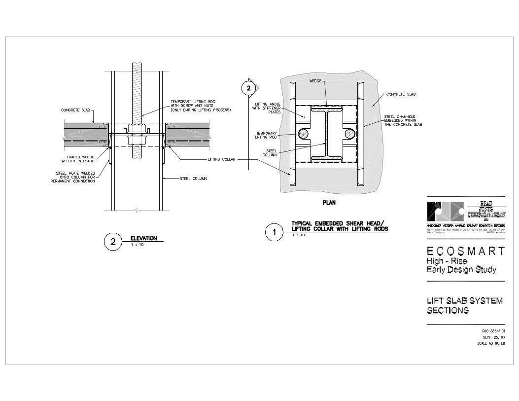
3.1 Lift Slab Construction Description
The Lift Slab System is comprised of cast on site post-tensioned concrete slabs
supported on steel columns. The post-tensioned concrete slabs are cast on top of
each other on the ground or podium floor with plastic sheets or a chemical
separator compound dividing them. The lowest level slab is cast first, with
subsequent slabs poured directly on top of the preceding one. Steel shear heads
are embedded within the slab around the columns to form an opening to facilitate
the lifting process as well as a lifting attachment point and a welded connection
point to the steel columns.
Some earlier projects utilized conventional reinforced concrete flat plates as well
as beam and slab configurations. However, currently post-tensioned slabs are
normally used for better lifting performance and also have the advantage of
reduced concrete thickness. In Vancouver the minimum slab thickness is usually
7½” due to mechanical ducts located within the slab. Though this was originally
a requirement of the original Terms of Reference for this study, in order to take
full advantage of the efficiency of post-tensioned construction to reduce the
required slab thickness, we have reduced the slab thickness to 6½” for this
particular project and assumed the mechanical ducts are placed beneath the slab in
a bulk head against a partition wall which is commonly done in other parts of
North America. A 6½” slab thickness was assumed for this study. (See Appendix
A for details of a typical floor plate).
Lift slab construction has historically been used on projects in the 4 to 8 storey
range. The tallest lift slab structure we are aware of is 18 storeys. This 22 storey is
therefore taller than any other previous project and is therefore certainly “pushing
the envelope”.
High-Rise Early Design Study – Stage 2 Page 8 EcoSmart Concrete Project RJC# : 38647.02 February 6, 2004
Before the lifting process commences all concrete slabs are tensioned at ground
level. This has the advantage of eliminating the awkwardness of performing
tensioning above-grade. The post tensioning increases the slabs spanning
capabilities relative to thickness and thus can reduce the number of columns and,
therefore, the number of jacking points. Furthermore, most of the concrete creep
and shrinkage takes place on the ground and the restraint induced cracking of the
floor slab is reduced. However, the post-tensioned strands must be protected from
moisture ingress both during and after construction to ensure a long lasting,
durable structural system.
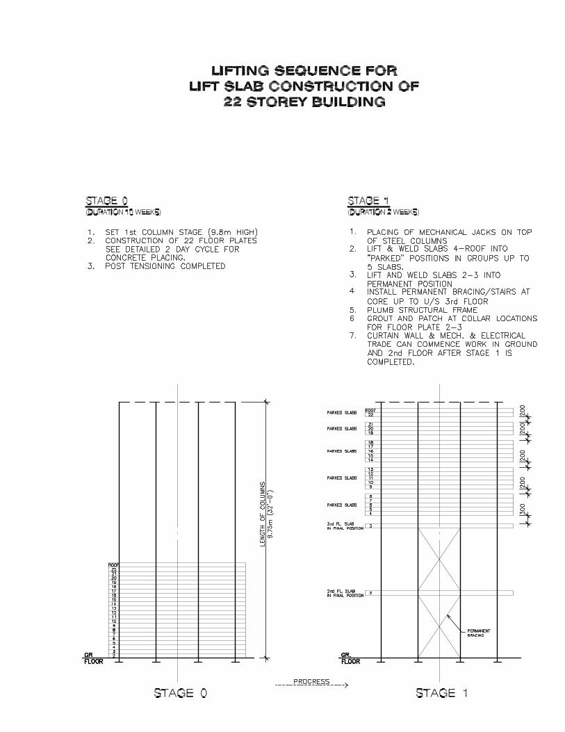
After all slabs are poured at grade and cured, mechanical jacks mounted on steel
castings that are supported on top of the steel columns lift the floor slabs at a rate
of a few centimeters an hour sequentially into their respective positions. The steel
columns are designed as cantilever columns above the slab that serves as a
working platform to limit the unbraced length of columns and ensure temporary
stability. The number of slabs lifted at one time varies between 2-5 depending on
the jack capacity and floor configuration.
While the slabs are parked in temporary positions they are supported by wedges
and tack welds to the steel columns. The lowest slab is parked in its final position
and new sections of steel columns are spliced on top of existing columns (usually
2-storeys above working platform). The lifting process carries on while workers
continue to work below finishing the permanent connections between columns
and slabs.
Structural components such as cross bracing or shearwalls providing lateral
stability for the building are installed at lower levels while lifting is proceeding
above.
(See Appendix A for a description of the detailed lifting sequence proposed for
this building).
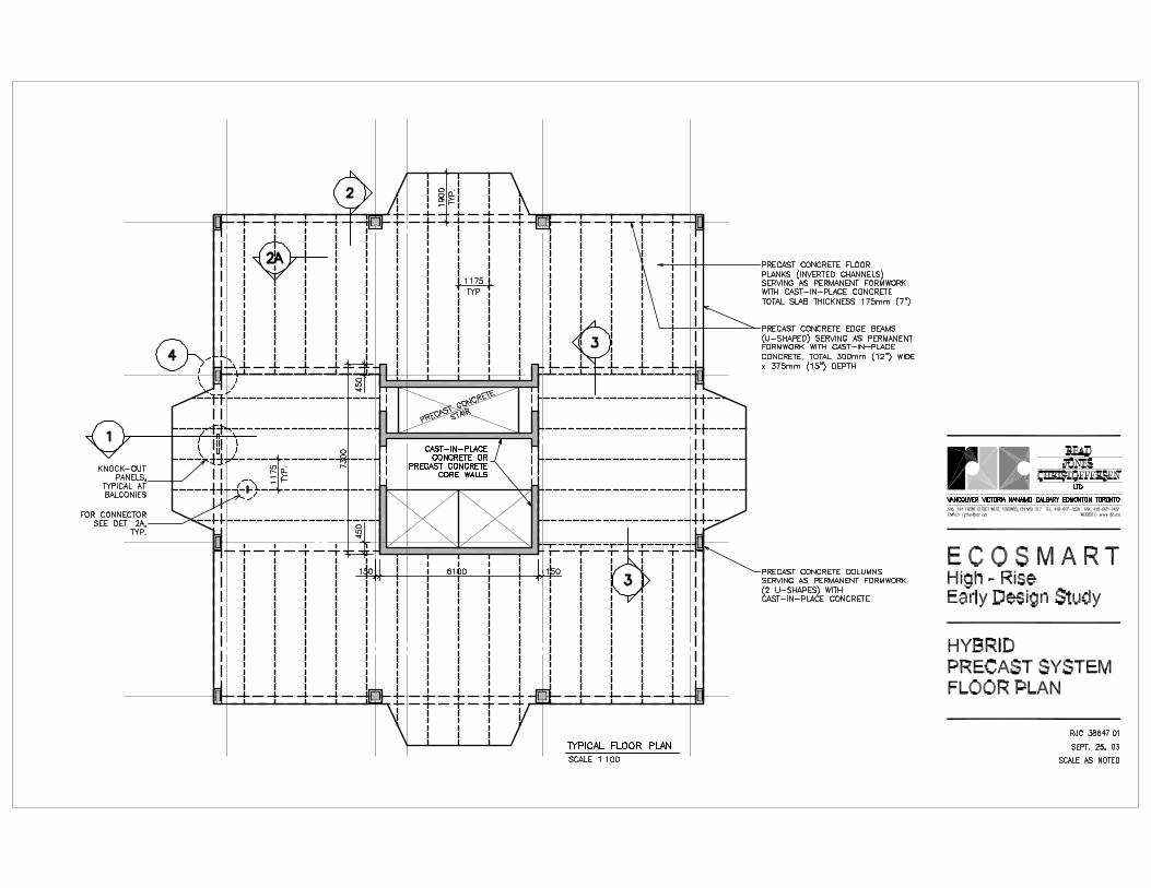
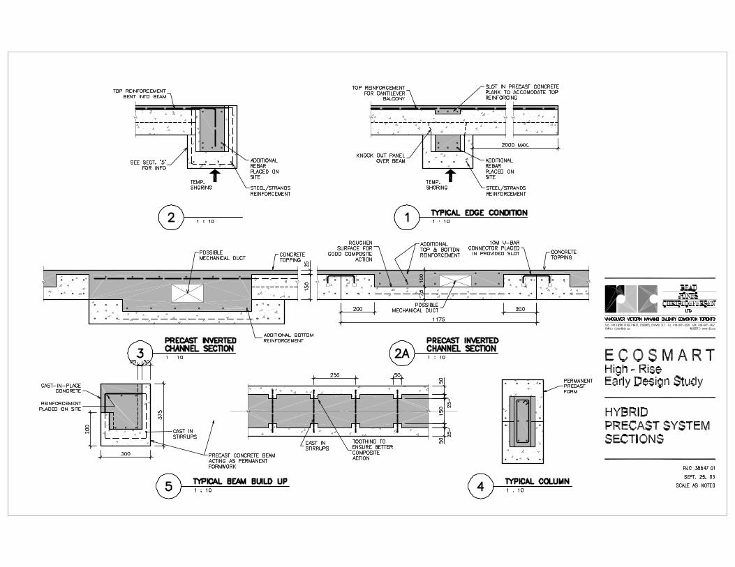
High-Rise Early Design Study – Stage 2 Page 9 EcoSmart Concrete Project RJC# : 38647.02 February 6, 2004 3.2 Hybrid Precast Description
This hybrid composite system consists of precast / prestressed concrete elements
that are shop manufactured combined with field cast concrete topping. The
precast elements in this example consist of inverted channel elements for the
typical slab portions which are supported on precast concrete ‘U’ shaped beam
forms. Column forms can also be similarly fabricated or normally constructed
cast-in-place columns could be used. See Appendix B for the proposed typical
floor slab of this building. The precast forms could be cast in a certified precast
concrete plant with as much SCM’s as possible or they could be field cast on site,
depending on site configuration and weather. Our initial findings indicate a
possible range of 20%-25% SCM’s. These forms need to reach sufficient strength
to be lifted out of the mould after 24 hours in order to maintain an economical
viable production cycle for a precast plant. This time constraint governs the SCM
content.
The in deck mechanical ducts are assumed to be cast into the field poured
concrete topping as shown in Section 2A of Appendix B.
The precast column and beam forms are shipped to site and erected and
temporarily shored and secured by steel clamps or normal cast-in-place concrete
columns could be formed and poured. The floor channels are placed onto the
precast concrete beam forms and additional steel reinforcement is placed and tied.
A high SCM content concrete mix is then field poured into the beam and column
forms, as well as the channel forms to finish the floor slab. The beam shores are
left in place until the field cast concrete has reached sufficient strength.
Temporary shoring could be reduced if the precast panels were designed to span
further under the weight of wet concrete. This would produce thicker precast
elements, however, resulting in greater shipment costs and reduced use of field
cast high SCM concrete. An economical balance also has to be established
High-Rise Early Design Study – Stage 2 Page 10 EcoSmart Concrete Project RJC# : 38647.02 February 6, 2004
between shoring cost and floor thickness. The use of temporary shoring allows
reduced total floor thicknesses and reduced precast concrete thickness.
3.3 Bubble Deck Slab System
In the course of our research for this study we came across a hybrid precast/cast-
in-place concrete system that has been developed in Europe and is being used in
the construction of high rise buildings in Holland. Additional information about
this system is contained in Appendix C.
In general principal, the system is very similar to the Hybrid Precast system
developed for this study. It also consists of a thin shop fabricated concrete panel
shipped to site, lifted into a place with a cast-in-place concrete topping added.
However, the thin concrete bottom layer is stiffened by a top and bottom grid of
heavy welded wire mesh tied together by vertical shear steel. The space between
the top and bottom grid of steel is filled with large plastic spheres which both
reduces the final structural weight and reduces the final volume of concrete used.
The panel is shipped to site with the bottom layer of concrete, top and bottom
steel grid and plastic spheres in place. The field poured concrete fills the spaces
between the spheres. This system is now being licensed to fabricators in Canada
and should soon be available for use.
High-Rise Early Design Study – Stage 2 Page 11 EcoSmart Concrete Project RJC# : 38647.02 February 6, 2004 4.0 CONSTRUCTION COST ESTIMATES
Due to the competitive nature of property development, especially in the high rise
condominium market, the initial construction cost of a building is one of the
primary driving factors in private construction in North America. More often
than not it dictates other design criteria and short term financial gains are viewed
more important than longer life cycles and better design of the building.
Therefore any structural system that is potentially more sustainable than
commonly used construction methods must at least be initially as financially
viable as the common base scheme. The comparative base scheme is the cast-in-
place concrete flat plate scheme with minimum fly ash content. This is presently
the most commonly used system in high rise residential construction both in
Vancouver and across Canada.
The structural schemes were broken down into their respective elements and the
calculated quantities of materials were multiplied by unit costs to arrive at a total
cost of construction. The unit costs are based on Hanscomb’s Yardsticks for
Costing 2003 with some variations based on Read Jones Christoffersen Ltd.
experience which reflects current cost fluctuations within the Vancouver market.
For example, formwork in the Vancouver market is currently more expensive than
usual due to a current shortage of plywood. Additionally, Read Jones
Christoffersen Ltd. contacted specialist contractors for their unique expert input.
RJC and Yolles agreed between themselves on the value of unit costs issued in
order to make comparisons between the two studies possible. The unit costs used
are shown in Table 1.
Only the cost of the structural elements above the ground floor or podium deck is
included in this comparison. For the purpose of this study, it has been assumed
that the structural systems below the alternative typical floor systems would be
identical, and therefore assumed to have the same cost. Any variation in
foundation cost resulting from lighter weight systems was noted to be relatively

High-Rise Early Design Study – Stage 2 Page 12 EcoSmart Concrete Project RJC# : 38647.02 February 6, 2004
small, well within the likely margin of error of this study and therefore not
included. Curtain wall costs are included to the extent that differing floor-to-floor
height influence that cost.
The costs calculated in the following tables for the construction of the structure of
the building represents our opinion of the probable cost of construction based on
the limited information obtained during this study. They are based on unit costs
generally recognised in the industry as representative and our estimate of
construction time and schedule. Some of the schemes, reviewed are not
commonly used in this type of construction. Therefore a good body of costing
information simply is not available. Final costs cannot be determined until such
time that the work is designed in detail, tendered and the final quantities and
methods of construction are defined. It is not possible to accurately forecast the
final unit prices that may be tendered for the work as they are directly related to
the construction climate at the time of tendering. The cost estimates should
therefore be treated as “ball park” figures only for comparison use and cannot be
guaranteed.
A helpful assessment tool for comparison is the sub total that summarizes the cost
of the major elements alone. This allows for a more detailed comparison and
future combination of the most efficient and most sustainable elements of the
various structural schemes which have been studied.
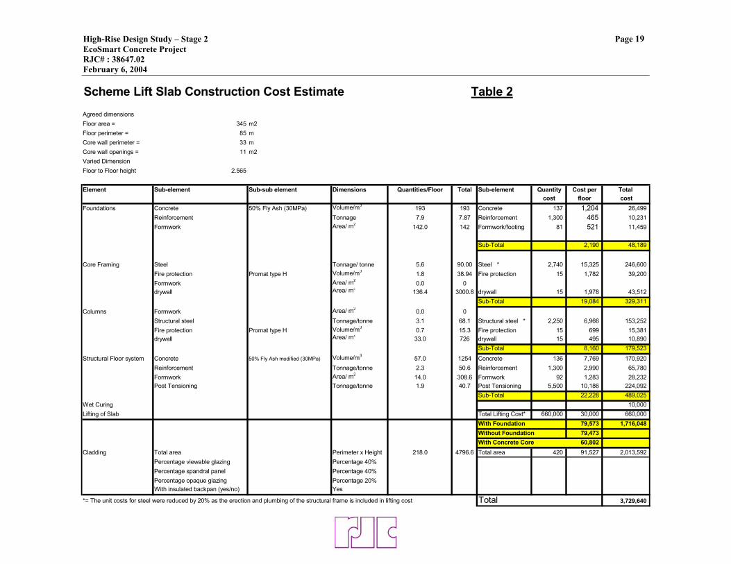
4.1 Lift Slab Construction Cost
The cost estimate break down and calculation for this scheme are shown in Table
2. the total calculated estimated cost for this scheme is $1,716,048.00 or
$226.10/m2 ($21.00/sq foot). This cost is based on our estimate of construction
cost of the structure only and does not include the economic impact of schedule.
This cost compares with an estimated $1,703,774 or $224.48 per m2 ($20.85/sq ft)
for the base flat plate scheme.
High-Rise Early Design Study – Stage 2 Page 13 EcoSmart Concrete Project RJC# : 38647.02 February 6, 2004
In summary, the materials and costs for this system break down as follows:
Quantity Total Costs Cost $/m2 %
Concrete 1447 m3 $197,419 $26.00 11.5
Formwork 451 m2 $39,691 $5.20 2.3
Mild Rebar 58.5 tonne $76,011 $10.00 4.4
P/T Reinforced 40.7 tonne $224,092 $29.50 13.1
Structural Steel 158.1 tonne $399,852 $52.70 23.3
Slab Lifting 10 stages $660,000 $87.00 38.4
Fire Protection 54.24m3 $54,581 $7.20 3.2
Drywall 3726 m2 $54,402 $7.20 3.2
Wet Curing 7590m2 $10,000 $1.30 0.6
Total $1,716,048 $226.10 100
An estimate of $10,000.00 has been added to the cost to account for the need to
wet cure the high fly ash content slab for the relatively short period between their
casting, setting, and covering by the new slab poured on top. This curing
requirement is in accordance with the proposed new CSA A23.1 Standard,
Concrete Materials and Methods of Concrete Construction (Committee Draft).
This proposed revision to the existing standard will require a 7-day wet cure for
concrete with a fly ash content in excess of 35% or 40% for slag.
This scheme is affected by the very low formwork cost which is offset by the cost
of slab lifting and the higher cost of post-tensioning steel.
The breakdown on a per floor basis indicates that the steel cross braced core
framing accounts for approximately 20 % and the concrete floor plate for are
approximately 30% of the total construction cost. The perimeter columns do not
have a significant impact on the overall per floor cost and present approximately
High-Rise Early Design Study – Stage 2 Page 14 EcoSmart Concrete Project RJC# : 38647.02 February 6, 2004
10% of the total. The largest contribution is the lifting and steel erection cost with
almost 39%.
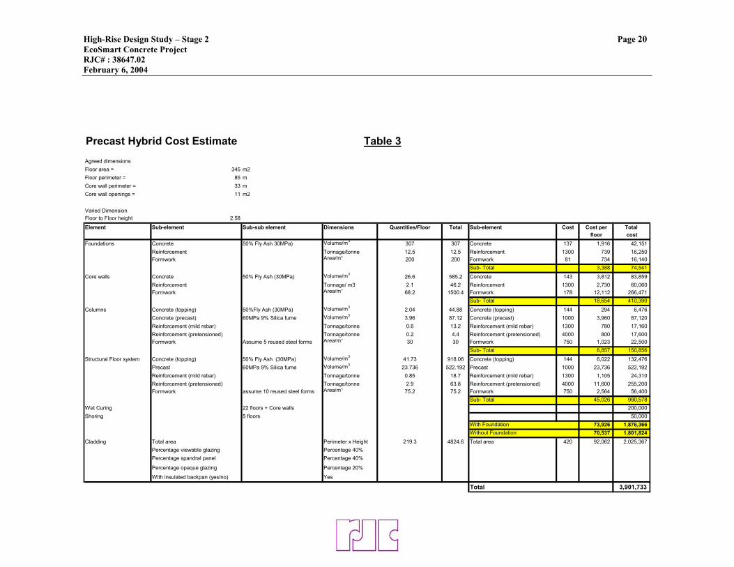
4.2 Hybrid Precast Scheme Cost
The cost estimates and breakdown for this section is shown in Table 3. the total
calculated estimated cost for this scheme is $1,876,365.00 or $247.1/m2
($17.90/sq ft). This cost is based on our estimate of the construction cost of the
structure only and does not include the economic impact of schedule. This cost
compares with a cost of $1,703,774 or $224.48 per m2 ($20.85/sq ft) for the base
flat plate scheme.
In summary, the materials and costs for this system break down as follows:
Quantity Total Costs Cost $/m2 %
Cast-in-place Concrete
1855m3 $264,962 $34.90 14.12
Precast Concrete 610m3 $609,312 $80.30 32.5
Wet Curing 9090 m2 $200,000 $26.30 10.6
Mild Rebar 90.6 tonne $117,780 $15.60 6.3
Prestressed Rebar 68.2 tonne $272,800 $35.90 14.5
Formwork/PC 1805 m2 $361,511 $47.60 19.3
Shoring $50,000 $6.60 2.7
Total $1,876,365 $247.20 100
This scheme also has a relatively low form work cost which is partially offset by
the higher unit rate for the precast concrete forms and cost of the precast concrete
elements.
High-Rise Early Design Study – Stage 2 Page 15 EcoSmart Concrete Project RJC# : 38647.02 February 6, 2004
Customized forms for the precast elements, which are constructed of steel with a
special plastic coating have a significantly higher unit cost than normal slab
formwork but are more than offset by their much smaller quantity and extent of
reuse. The estimated fabrication cost for these forms which ensure a faster curing
and quality finished concrete are approximately $970.00 per square metre ($90.00
per square foot) for first time production but can be reused up to 500 times. After
such extensive usage the forms will need to be overhauled to maintain their
quality. To overhaul a used form, which usually consists of replacing the inside
liner of the form, costs approximately $485.00 per square metre ($45.00 per
square foot). As there are typical planks on this floor plate it was assumed that 10
forms would be required which will be overhauled at least once for an average
cost of $750.00 per square metre ($70.00 per square foot). This appears to be a
high unit cost but accounts for only 9% of the cost with the floor system alone,
due to the repetitive production cycle of precast construction.
The foundation costs are higher than the other reviewed structural systems due to
the increased overall building weight due to the thicker floor slab required.
However this does not contribute significantly to the overall cost as foundations
only amount to 4% of the overall cost, and have therefore not been included in the
comparison of costs.
A cost estimate of $200,000.00 has been included for wet curing of the high SCM
content cast-in-place concrete topping as required by the new CSA A23.1
Standard Concrete Materials and Methods of Concrete Construction (Committee
Draft). This is the same cost carried in the Yolles base flat plate system
comparator.
The greatest cost benefit for the Hybrid Precast System is that on site formwork is
almost eliminated. Even though the material cost is higher for precast formwork
than ordinary formwork the repetitive nature of precast fabrication saves costs.
For the cast-in-place base scheme the formwork for the slabs accounts for
High-Rise Early Design Study – Stage 2 Page 16 EcoSmart Concrete Project RJC# : 38647.02 February 6, 2004
approximately 20% of the overall cost and on this precast building the precast
forms of the slab elements account for 2%.
4.3 Cost Impact of Schedule
In addition to the direct construction cost for each structural system reviewed
there is a secondary cost affect related to construction schedule. This cost has two
principal components, contractor cost and financing costs. Based on discussions
with residential contractors and developers we have assumed the contracting
costs, made up of insurance and bonding costs, head office costs, site staffing
costs, and equipment rental to be $50,000.00/week. We have assumed cost of
financing of the building at a 5% interest rate based on a total carrying cost of two
times the total construction cost of the building to account for land costs and soft
costs. We have assumed a total building cost of $110/sq ft and a total building
area of 81,700.00 sq ft. this works out to a carrying cost of approximately
$17,300.00 per wk.
We have, therefore, assumed a total cost implication of $70,000.00/wk for
construction schedule differentials.
The estimated construction schedule for the Lift Slab Scheme is shown in
Appendix A and is estimated to be 28 weeks. The estimated construction schedule
for the Hybrid Precast concrete scheme is shown in Appendix B and is estimated
to be 21 weeks. The base building scheme of a normally reinforced concrete flat
plate as outlined in the Yolles report is estimated to be 22 weeks.
Therefore the cost impact for the lift slab system is +$445,500.00 (+$58.7/m2) and
the Hybrid system is -$70,000.00 (-$9.2/m2).
High-Rise Early Design Study – Stage 2 Page 17 EcoSmart Concrete Project RJC# : 38647.02 February 6, 2004 4.4 Cost Impact of Exterior Cladding
This Stage 2 High Rise Early Design Study primarily focuses on the comparison
of structural systems only. All other building systems, such as
mechanical/electrical systems, interior finishes, elevators, and cladding etc. are
assumed equal for all alternative structural schemes. The only exception to this,
included in this review is the relative cost of the exterior cladding affected by the
differential floor-to-floor height of the various schemes. The floor and ceiling
height of all schemes has been set at 2,400mm, therefore, due to different
structural thicknesses for different floor plates the floor-to-floor heights will vary
and thus affect the overall height of the building.
The exterior cladding is the most cost intensive system affected by this change in
height, and therefore has been included both in the cost comparison and the
primary energy and greenhouse gas emission study.
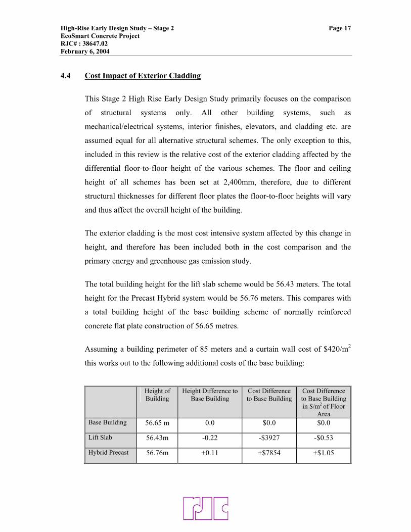
The total building height for the lift slab scheme would be 56.43 meters. The total
height for the Precast Hybrid system would be 56.76 meters. This compares with
a total building height of the base building scheme of normally reinforced
concrete flat plate construction of 56.65 metres.
Assuming a building perimeter of 85 meters and a curtain wall cost of $420/m2
this works out to the following additional costs of the base building:
Height of Building
Height Difference to Base Building
Cost Difference to Base Building
Cost Difference to Base Building in $/m2 of Floor
Area Base Building 56.65 m 0.0 $0.0 $0.0
Lift Slab 56.43m -0.22 -$3927 -$0.53
Hybrid Precast 56.76m +0.11 +$7854 +$1.05
High-Rise Early Design Study – Stage 2 Page 18 EcoSmart Concrete Project RJC# : 38647.02 February 6, 2004
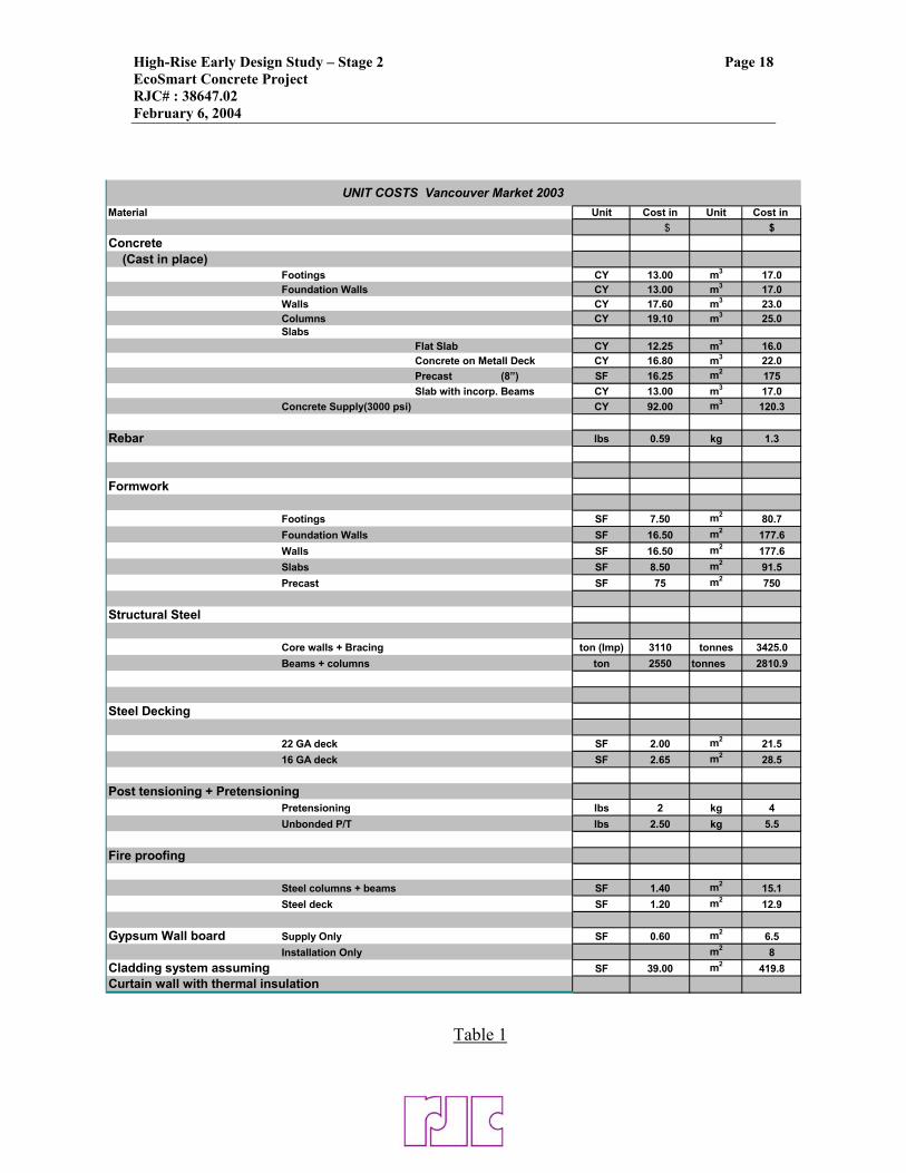
Material Unit Cost in Unit Cost in $ $
Concrete (Cast in place)
Footings CY 13.00 m3 17.0Foundation Walls CY 13.00 m3 17.0Walls CY 17.60 m3 23.0Columns CY 19.10 m3 25.0Slabs
Flat Slab CY 12.25 m3 16.0Concrete on Metall Deck CY 16.80 m3 22.0Precast (8”) SF 16.25 m2 175Slab with incorp. Beams CY 13.00 m3 17.0
Concrete Supply(3000 psi) CY 92.00 m3 120.3
Rebar lbs 0.59 kg 1.3
Formwork
Footings SF 7.50 m2 80.7Foundation Walls SF 16.50 m2 177.6Walls SF 16.50 m2 177.6Slabs SF 8.50 m2 91.5Precast SF 75 m2 750
Structural Steel
Core walls + Bracing ton (Imp) 3110 tonnes 3425.0Beams + columns ton 2550 tonnes 2810.9
Steel Decking
22 GA deck SF 2.00 m2 21.516 GA deck SF 2.65 m2 28.5
Post tensioning + PretensioningPretensioning lbs 2 kg 4Unbonded P/T lbs 2.50 kg 5.5
Fire proofing
Steel columns + beams SF 1.40 m2 15.1Steel deck SF 1.20 m2 12.9
Gypsum Wall board Supply Only SF 0.60 m2 6.5Installation Only m2 8
Cladding system assuming SF 39.00 m2 419.8Curtain wall with thermal insulation
UNIT COSTS Vancouver Market 2003
Table 1
High-Rise Design Study – Stage 2 Page 19 EcoSmart Concrete Project RJC# : 38647.02 February 6, 2004
Agreed dimensionsFloor area = 345 m2Floor perimeter = 85 mCore wall perimeter = 33 mCore wall openings = 11 m2Varied DimensionFloor to Floor height 2.565
Element Sub-element Sub-sub element Dimensions Quantities/Floor Total Sub-element Quantity Cost per Total cost floor cost
Foundations Concrete 50% Fly Ash (30MPa) Volume/m3 193 193 Concrete 137 1,204 26,499 Reinforcement Tonnage 7.9 7.87 Reinforcement 1,300 465 10,231 Formwork Area/ m2 142.0 142 Formwork/footing 81 521 11,459
Sub-Total 2,190 48,189
Core Framing Steel Tonnage/ tonne 5.6 90.00 Steel * 2,740 15,325 246,600 Fire protection Promat type H Volume/m3 1.8 38.94 Fire protection 15 1,782 39,200 Formwork Area/ m2 0.0 0drywall Area/ m2
136.4 3000.8 drywall 15 1,978 43,512 Sub-Total 19,084 329,311
Columns Formwork Area/ m2 0.0 0Structural steel Tonnage/tonne 3.1 68.1 Structural steel * 2,250 6,966 153,252 Fire protection Promat type H Volume/m3 0.7 15.3 Fire protection 15 699 15,381 drywall Area/ m2
33.0 726 drywall 15 495 10,890 Sub-Total 8,160 179,523
Structural Floor system Concrete 50% Fly Ash modified (30MPa) Volume/m3 57.0 1254 Concrete 136 7,769 170,920 Reinforcement Tonnage/tonne 2.3 50.6 Reinforcement 1,300 2,990 65,780 Formwork Area/ m2 14.0 308.6 Formwork 92 1,283 28,232 Post Tensioning Tonnage/tonne 1.9 40.7 Post Tensioning 5,500 10,186 224,092
Sub-Total 22,228 489,025 Wet Curing 10,000 Lifting of Slab Total Lifting Cost* 660,000 30,000 660,000
With Foundation 79,573 1,716,048 Without Foundation 79,473 With Concrete Core 60,802
Cladding Total area Perimeter x Height 218.0 4796.6 Total area 420 91,527 2,013,592 Percentage viewable glazing Percentage 40%Percentage spandral panel Percentage 40%Percentage opaque glazing Percentage 20%With insulated backpan (yes/no) Yes
Total 3,729,640
Table 2Scheme Lift Slab Construction Cost Estimate
*= The unit costs for steel were reduced by 20% as the erection and plumbing of the structural frame is included in lifting cost
High-Rise Design Study – Stage 2 Page 20 EcoSmart Concrete Project RJC# : 38647.02 February 6, 2004
Agreed dimensionsFloor area = 345 m2Floor perimeter = 85 mCore wall perimeter = 33 mCore wall openings = 11 m2
Varied DimensionFloor to Floor height 2.58
Element Sub-element Sub-sub element Dimensions Quantities/Floor Total Sub-element Cost Cost per Total floor cost
Foundations Concrete 50% Fly Ash 30MPa) Volume/m3 307 307 Concrete 137 1,916 42,151 Reinforcement Tonnage/tonne 12.5 12.5 Reinforcement 1300 739 16,250 Formwork Area/m2
200 200 Formwork 81 734 16,140 Sub- Total 3,388 74,541
Core walls Concrete 50% Fly Ash (30MPa) Volume/m3 26.6 585.2 Concrete 143 3,812 83,859 Reinforcement Tonnage/ m3 2.1 46.2 Reinforcement 1300 2,730 60,060 Formwork Area/m2
68.2 1500.4 Formwork 178 12,112 266,471 Sub- Total 18,654 410,390
Columns Concrete (topping) 50%Fly Ash (30MPa) Volume/m3 2.04 44.88 Concrete (topping) 144 294 6,476 Concrete (precast) 60MPa 9% Silica fume Volume/m3 3.96 87.12 Concrete (precast) 1000 3,960 87,120 Reinforcement (mild rebar) Tonnage/tonne 0.6 13.2 Reinforcement (mild rebar) 1300 780 17,160 Reinforcement (pretensioned) Tonnage/tonne 0.2 4.4 Reinforcement (pretensioned) 4000 800 17,600 Formwork Assume 5 reused steel forms Area/m2
30 30 Formwork 750 1,023 22,500 Sub- Total 6,857 150,856
Structural Floor system Concrete (topping) 50% Fly Ash (30MPa) Volume/m3 41.73 918.06 Concrete (topping) 144 6,022 132,476 Precast 60MPa 9% Silica fume Volume/m3 23.736 522.192 Precast 1000 23,736 522,192 Reinforcement (mild rebar) Tonnage/tonne 0.85 18.7 Reinforcement (mild rebar) 1300 1,105 24,310 Reinforcement (pretensioned) Tonnage/tonne 2.9 63.8 Reinforcement (pretensioned) 4000 11,600 255,200 Formwork assume 10 reused steel forms Area/m2
75.2 75.2 Formwork 750 2,564 56,400 Sub- Total 45,026 990,578
Wet Curing 22 floors + Core walls 200,000 Shoring 5 floors 50,000
With Foundation 73,926 1,876,366 Without Foundation 70,537 1,801,824
Cladding Total area Perimeter x Height 219.3 4824.6 Total area 420 92,062 2,025,367 Percentage viewable glazing Percentage 40%Percentage spandral panel Percentage 40%
Percentage opaque glazing Percentage 20%
With insulated backpan (yes/no) Yes
Total 3,901,733
Table 3Precast Hybrid Cost Estimate
High-Rise Design Study – Stage 2 Page 21 EcoSmart Concrete Project RJC# : 38647.02 February 6, 2004 5.0 CONSTRUCTION SCHEDULE COMPARISON
In addition to a cost estimate we have also undertaken an estimated construction
schedule for each of the two schemes reviewed as part of this Stage 2 Study, as
speed of construction has a direct relation to the construction cost of the project.
The base schedule used as a comparative is the normally reinforced cast-in-place
concrete flat plate scheme with 9% SCM as reviewed n the Yolles report. Based
on the review of this system undertaken by Yolles we have taken this base
construction schedule as 22 weeks for the typical floors above the podium deck.
It was agreed between RJC and Yolles that only the construction schedule for the
typical floor tower portion of the project would be compared. It was assumed that
the foundations, below grade portion, and any grade level or podium structure
would have the same construction schedule and cost for all schemes.
The estimated construction schedule for both of the lift slab scheme and the
Hybrid concrete scheme was developed from first principals by RJC personnel
based on specialist input from contractors. These systems are not in common
usage in Canada for this type of structure, so there is not a good track record in
the construction industry on the time requirements for their construction.
Therefore these schedules should be viewed as approximate estimates only with a
possible margin of error.
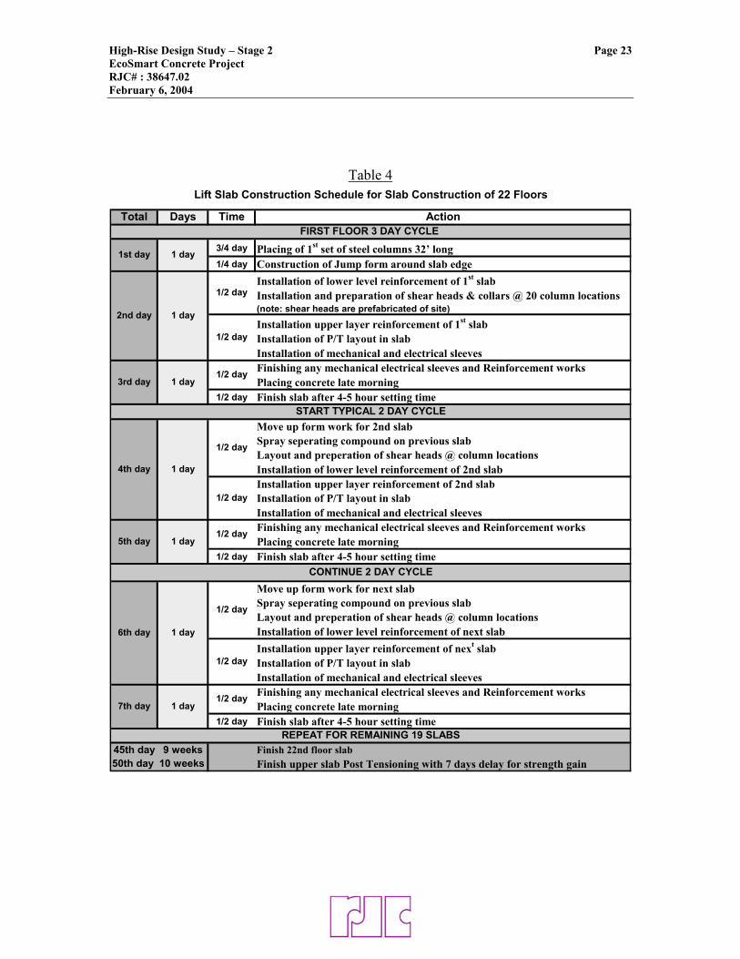
5.1 Lift Slab Construction Schedule
The construction of the lift slab system comprises of two main phases. Initially,
the floor slab is constructed at ground level with each slab poured on top of the
previous slab, separated by a release agent. The slab edge is formed, the mild and
post-tensioning steel placed, the concrete poured, the surface finished, and once
cured the release agent is applied to the top surface, then the process is repeated
High-Rise Design Study – Stage 2 Page 22 EcoSmart Concrete Project RJC# : 38647.02 February 6, 2004
and each slab poured on top of the one below. Once the concrete reaches
sufficient strength the post-tensioned strands are tightened. We estimate this
phase to take 10 weeks for this project based on a 2 day casting cycle as indicated
in Table 4.
The second phase is the lifting process itself. The lifting process cannot
commence until all 22 floor plates are poured and the post tensioning is
completed. The post tensioning will be done on the lower slabs while the upper
slabs are still being constructed.
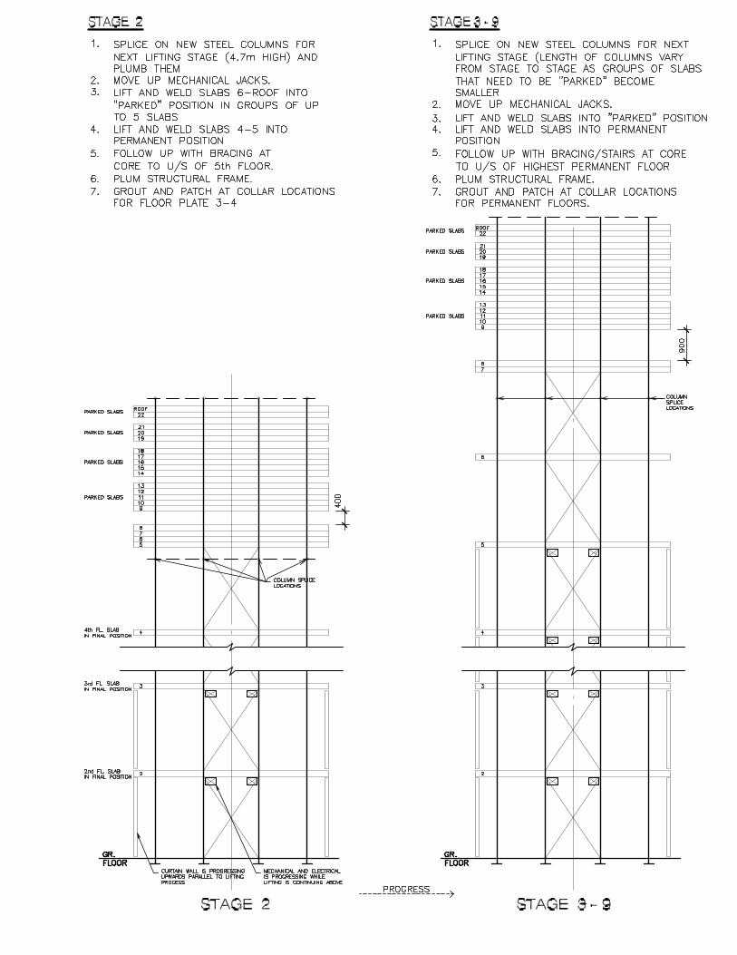
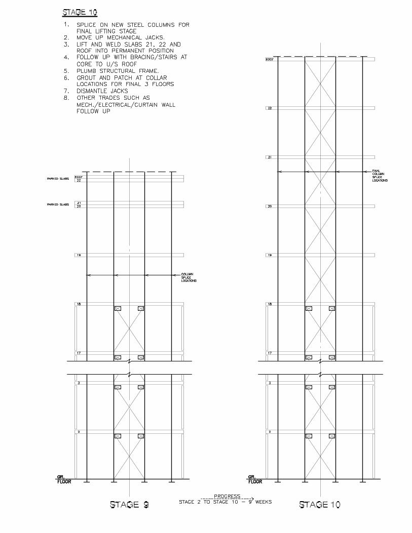
The lifting process is shown graphically in Appendix A. Only two levels of steel
columns are initially erected. All the slabs are then sequentially lifted (up to five
at a time) above the second floor and temporarily parked. The second floor slab
(the lowest of the lifted stack of slabs) is then permanently attached by welding
the embedded shear heads to the steel columns at its final location. New column
extensions are then added and the process is repeated.
The placement of the lower level floors take longer than the upper level floors due
to the increased number of floors that need to be handled and parked. Steel cross
bracing, or concrete core walls is added as the floors are lifted to maintain
structural stability. We estimate approximately 11 weeks for this lifting phase for
this building.
Once the 2nd and 3rd floors are locked in place the other trades can now access
these levels to complete their work. However, the slower pace of lifting at the
lower levels may create some delays in completing these levels.
The total estimated construction time for the Lift Slab system is 28 weeks.
High-Rise Design Study – Stage 2 Page 23 EcoSmart Concrete Project RJC# : 38647.02 February 6, 2004
Table 4
Total Days Time Action
3/4 day Placing of 1st set of steel columns 32’ long1/4 day Construction of Jump form around slab edge
Installation of lower level reinforcement of 1st slabInstallation and preparation of shear heads & collars @ 20 column locations (note: shear heads are prefabricated of site)
Installation upper layer reinforcement of 1st slabInstallation of P/T layout in slabInstallation of mechanical and electrical sleevesFinishing any mechanical electrical sleeves and Reinforcement worksPlacing concrete late morning
1/2 day Finish slab after 4-5 hour setting time
Move up form work for 2nd slabSpray seperating compound on previous slabLayout and preperation of shear heads @ column locationsInstallation of lower level reinforcement of 2nd slabInstallation upper layer reinforcement of 2nd slabInstallation of P/T layout in slabInstallation of mechanical and electrical sleevesFinishing any mechanical electrical sleeves and Reinforcement worksPlacing concrete late morning
1/2 day Finish slab after 4-5 hour setting time
Move up form work for next slabSpray seperating compound on previous slabLayout and preperation of shear heads @ column locationsInstallation of lower level reinforcement of next slabInstallation upper layer reinforcement of next slabInstallation of P/T layout in slabInstallation of mechanical and electrical sleevesFinishing any mechanical electrical sleeves and Reinforcement worksPlacing concrete late morning
1/2 day Finish slab after 4-5 hour setting time
45th day 9 weeks Finish 22nd floor slab50th day 10 weeks Finish upper slab Post Tensioning with 7 days delay for strength gain
Lift Slab Construction Schedule for Slab Construction of 22 Floors
1st day
2nd day
1/2 day1 day3rd day
1/2 day
1/2 day
1 day
1 day
6th day 1 day
1/2 day
1/2 day
5th day
1/2 day
1/2 day
1 day
START TYPICAL 2 DAY CYCLE
FIRST FLOOR 3 DAY CYCLE
REPEAT FOR REMAINING 19 SLABS
7th day 1 day1/2 day
CONTINUE 2 DAY CYCLE
4th day
1/2 day1 day
High-Rise Design Study – Stage 2 Page 24 EcoSmart Concrete Project RJC# : 38647.02 February 6, 2004 5.2 Hybrid Precast System Construction Schedule
Our analysis indicates that a 4 day per floor construction cycle, equal to the cast-
in-place concrete flat plate base system, can be achieved for this system (see
Table 5). The schedule of the precast scheme is driven mainly by the cranage time
required to lift the precast planks, beams and column halves into their respective
positions. The column and beam sections require more lifting time due to the
extra time required to plum the elements and tack weld them into position.
Precast Contractors indicated that an average of 30 minutes for these elements
should suffice. For the typical precast planks that only need to be lifted into place
and are supported by the core walls and the perimeter beams the lifting time is
estimated to be an average of 15 minutes per element.
The reinforcement cages can be tied by the rebar crews concurrently with the
precast lifting and then only need to be dropped into the columns and beams. The
rebar at the balconies and the welded wire mesh in the slab do not amount to
significant amount of work with respect to the schedule.
The cast-in-place concrete slab topping also fills the columns and beams to form a
monolithic structure and is placed during the late morning to give the finishers all
afternoon to finish the slab. The next morning lifting of formwork for the core
wall can commence.
The option of slip forming the core in advance was explored but no benefit was
found. It appears that the initial set up of the slip form would delay rather than
accelerate the schedule.
Another approach worth considering would be to replace the precast concrete
perimeter columns with cast-in-place columns. The lifting time would be reduced
as the column forms can be lifted and set plum more quickly by the forming crew.
Placing of the concrete would be at the same time as for the core walls.
Therefore, all horizontal elements would be precast with concrete topping and all
High-Rise Design Study – Stage 2 Page 25 EcoSmart Concrete Project RJC# : 38647.02 February 6, 2004
vertical elements could be cast in place. From an environmental and cost point of
view this would result in no significant change as the perimeter columns only
account for a low amount of greenhouse gases and costs.
Based on our analysis and schedule assumptions as indicated on the Hybrid
Precast Construction schedule in Appendix B, the construction time of this system
is 21 weeks. This is virtually identical to the 22-week schedule of the base
concrete flat plate system. The 1-week difference is due to the initial construction
time required for the fly forms for the flat plate system.
High-Rise Design Study – Stage 2 Page 26 EcoSmart Concrete Project RJC# : 38647.02 February 6, 2004
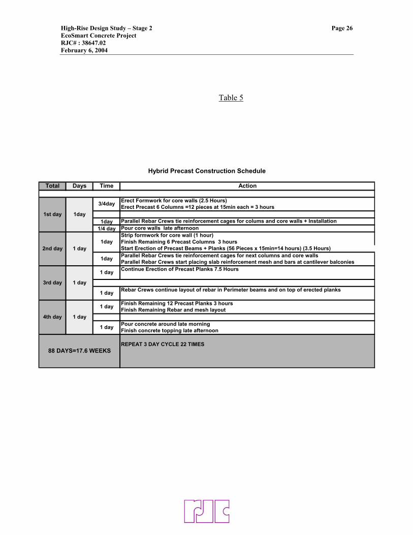
Table 5
Total Days Time Action
Erect Formwork for core walls (2.5 Hours)Erect Precast 6 Columns =12 pieces at 15min each = 3 hours
1day Parallel Rebar Crews tie reinforcement cages for colums and core walls + Installation1/4 day Pour core walls late afternoon
Strip formwork for core wall (1 hour)Finish Remaining 6 Precast Columns 3 hoursStart Erection of Precast Beams + Planks (56 Pieces x 15min=14 hours) (3.5 Hours)Parallel Rebar Crews tie reinforcement cages for next columns and core wallsParallel Rebar Crews start placing slab reinforcement mesh and bars at cantilever balconiesContinue Erection of Precast Planks 7.5 Hours
Rebar Crews continue layout of rebar in Perimeter beams and on top of erected planks
Finish Remaining 12 Precast Planks 3 hoursFinish Remaining Rebar and mesh layout
Pour concrete around late morningFinish concrete topping late afternoon
REPEAT 3 DAY CYCLE 22 TIMES88 DAYS=17.6 WEEKS
1st day
2nd day
3rd day
1 day
1 day
1 day
1day
1 day
1 day
Hybrid Precast Construction Schedule
1day
1 day
3/4day
1day
1 day4th day
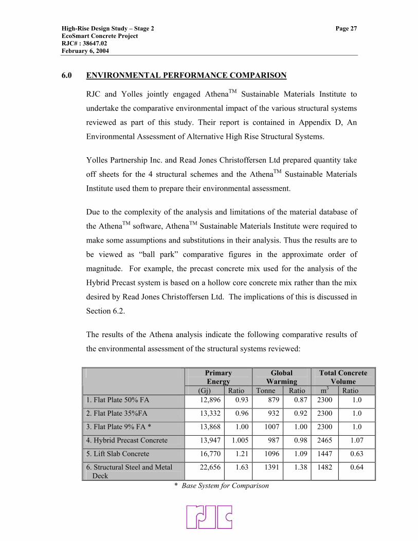
High-Rise Design Study – Stage 2 Page 27 EcoSmart Concrete Project RJC# : 38647.02 February 6, 2004 6.0 ENVIRONMENTAL PERFORMANCE COMPARISON
RJC and Yolles jointly engaged AthenaTM Sustainable Materials Institute to
undertake the comparative environmental impact of the various structural systems
reviewed as part of this study. Their report is contained in Appendix D, An
Environmental Assessment of Alternative High Rise Structural Systems.
Yolles Partnership Inc. and Read Jones Christoffersen Ltd prepared quantity take
off sheets for the 4 structural schemes and the AthenaTM Sustainable Materials
Institute used them to prepare their environmental assessment.
Due to the complexity of the analysis and limitations of the material database of
the AthenaTM software, AthenaTM Sustainable Materials Institute were required to
make some assumptions and substitutions in their analysis. Thus the results are to
be viewed as “ball park” comparative figures in the approximate order of
magnitude. For example, the precast concrete mix used for the analysis of the
Hybrid Precast system is based on a hollow core concrete mix rather than the mix
desired by Read Jones Christoffersen Ltd. The implications of this is discussed in
Section 6.2.
The results of the Athena analysis indicate the following comparative results of
the environmental assessment of the structural systems reviewed:
Primary Energy
Global Warming
Total Concrete Volume
(Gj) Ratio Tonne Ratio m3 Ratio 1. Flat Plate 50% FA 12,896 0.93 879 0.87 2300 1.0
2. Flat Plate 35%FA 13,332 0.96 932 0.92 2300 1.0
3. Flat Plate 9% FA * 13,868 1.00 1007 1.00 2300 1.0
4. Hybrid Precast Concrete 13,947 1.005 987 0.98 2465 1.07
5. Lift Slab Concrete 16,770 1.21 1096 1.09 1447 0.63
6. Structural Steel and Metal Deck
22,656 1.63 1391 1.38 1482 0.64
* Base System for Comparison
High-Rise Design Study – Stage 2 Page 28 EcoSmart Concrete Project RJC# : 38647.02 February 6, 2004
Based on the above comparative figures, it appears that the Hybrid Precast
structured system is virtually identical with the base system of Flat Plate with 9%
F.A. and the Lift Slab system exceeds the base system both in Primary Energy
(1.21), and Global Warning (1.09).
6.1 Lift Slab Construction
The environmental assessment concluded that the lift slab system consumes
approximately 20% more primary energy than the base system and also
contributes 9% more to the Global warming effect. The main contributor to these
higher numbers for this system appears to be due to the manufacturing process of
the structural steel columns and core cross bracing.
According to the AthenaTM Sustainable Materials Institute report (Appendix D),
the structural steel “primarily comes from integrated or virgin steel mills as
opposed to concrete reinforcing steel and steel wire strands which are
manufactured in mini-mills using almost entirely recycled steel as their primary
furnish. Typically, these mini-mills use about a third less energy to produce a
given quantity of steel and they are more abundant across the country. The
integrated producers are concentrated in Ontario and hence, transportation to
Vancouver is also factored into the profile results.”
A significant reduction in both primary energy and global warning could be
achieved by replacing the steel core with a cast-in-place concrete core. The
overall Energy consumption and GHG-emission would reduce drastically and
bring the Lift slab system closer to the Flat Plate and Hybrid Precast systems.
The Lift Slab System did not receive any beneficial accounting for the minimized
amount of formwork. The fly forms for the flat plate base scheme need to lifted
into place and the concrete bucket needs to travel a great number of times over a
long distance. On the lift slab system, however, the concrete is poured on the
High-Rise Design Study – Stage 2 Page 29 EcoSmart Concrete Project RJC# : 38647.02 February 6, 2004
ground and the finished slab only travels once to its permanent position. As it is
very difficult to determine the impact of this it was not taken into account.
Concrete when compared to steel appears to be more efficient with respect to
primary energy use and greenhouse gas emissions for this particular floor layout
based on the Athena analysis. It should be noted, however, that the Athena energy
analysis included only the embodied energy of materials from extraction,
manufacture, and construction and did not consider the full life cycle of the
materials. Therefore, the advantage of steel’s greater ease of demolition and its
better reuse or recycleability was not included in the analysis. Steel also becomes
more structurally efficient for larger floor spans, than used in this residential floor
plate as does post tensioning. Therefore, for residential construction with the
current structural floor spans and load criteria, concrete appears to be a more
suitable building material with respect to energy use and greenhouse gas
emissions.
6.2 Hybrid Precast System
The environmental performance of the Hybrid Precast System is within 5% of the
Flat Plate base system with 9% fly ash on greenhouse gas emissions and virtually
identical on Primary Energy use. This can be improved by having the columns
also cast-in-place concrete.
The floor system is the main contributor to the primary energy at almost 40% of
the total. The precast and concrete topping components contribute each almost the
same amount to GHG-emissions and primary energy use. This is due to the
higher volume of concrete topping which has a lower embodied energy per
volume than the precast concrete.
High-Rise Design Study – Stage 2 Page 30 EcoSmart Concrete Project RJC# : 38647.02 February 6, 2004
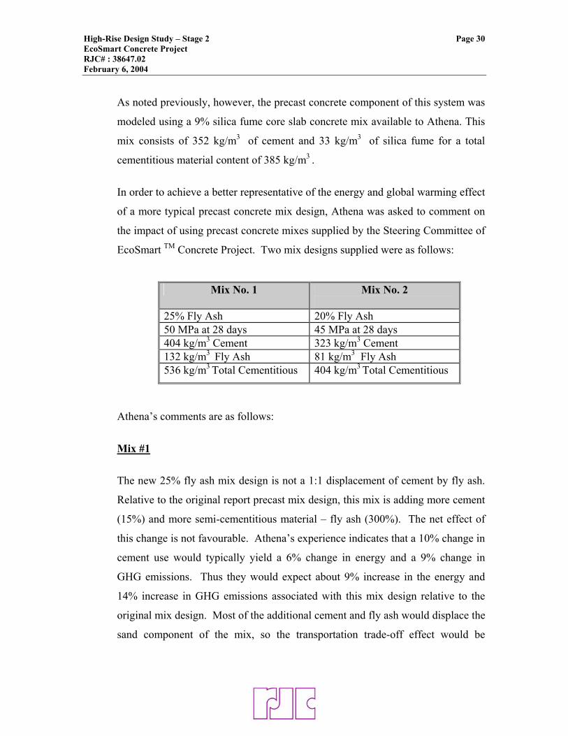
As noted previously, however, the precast concrete component of this system was
modeled using a 9% silica fume core slab concrete mix available to Athena. This
mix consists of 352 kg/m3 of cement and 33 kg/m3 of silica fume for a total
cementitious material content of 385 kg/m3 .
In order to achieve a better representative of the energy and global warming effect
of a more typical precast concrete mix design, Athena was asked to comment on
the impact of using precast concrete mixes supplied by the Steering Committee of
EcoSmart TM Concrete Project. Two mix designs supplied were as follows:
Mix No. 1 Mix No. 2
25% Fly Ash 20% Fly Ash 50 MPa at 28 days 45 MPa at 28 days 404 kg/m3 Cement 323 kg/m3 Cement 132 kg/m3 Fly Ash 81 kg/m3 Fly Ash 536 kg/m3 Total Cementitious 404 kg/m3 Total Cementitious
Athena’s comments are as follows:
Mix #1
The new 25% fly ash mix design is not a 1:1 displacement of cement by fly ash.
Relative to the original report precast mix design, this mix is adding more cement
(15%) and more semi-cementitious material – fly ash (300%). The net effect of
this change is not favourable. Athena’s experience indicates that a 10% change in
cement use would typically yield a 6% change in energy and a 9% change in
GHG emissions. Thus they would expect about 9% increase in the energy and
14% increase in GHG emissions associated with this mix design relative to the
original mix design. Most of the additional cement and fly ash would displace the
sand component of the mix, so the transportation trade-off effect would be
High-Rise Design Study – Stage 2 Page 31 EcoSmart Concrete Project RJC# : 38647.02 February 6, 2004
relatively minor in the scheme of things. The analysis excludes the impact of
replacing silica fume with fly ash.
Mix #2
The 20% fly ash mix design is also not a straight 1:1 replacement of cement, but
relative to the original study precast concrete mix design, the mix calls for less
cement and adds only half as much fly ash as the 25% FA case. Using the same
premise as above, Athena expects about a 5% reduction in energy use and a 7%
reduction in GHG, from the original findings.
An environmental benefit is also achieved by the amount of prefabrication that is
achieved with the precast elements. This reduces waste on site and plywood
usage.
High-Rise Design Study – Stage 2 Page 32 EcoSmart Concrete Project RJC# : 38647.02 February 6, 2004 7.0 CEMENT USAGE COMPARISON
The primary objective of the EcoSmart program is to reduce the amount of
Greenhouse Gas emission to the atmosphere from concrete construction. As one
of the principal strategies to do this is to reduce the cement content in concrete, a
comparative analysis of cement content in the various systems is of primary
interest.
Percentage Replacement Discussion When one specifies high percentage usage of supplementary cementitious
materials it is often assumed at a 1:1 replacement of cement by the SCM. This
may not always be true and individual mix designs should be reviewed to
determine the actual cement reduction.
According to the concrete mix design information received from and used by
Athena, as well as the mix design supplied by the Precast Industry, it appears that
the supplementary cementing materials (SCM’s) are not always replacing cement
on a 1:1 basis. This is also discussed in Section 6.2. It appears that when larger
percentages of SCM’s, especially Fly Ash, are introduced into a concrete mix,
additional cement is often added, apparently to offset the longer initial set time
that may otherwise result.
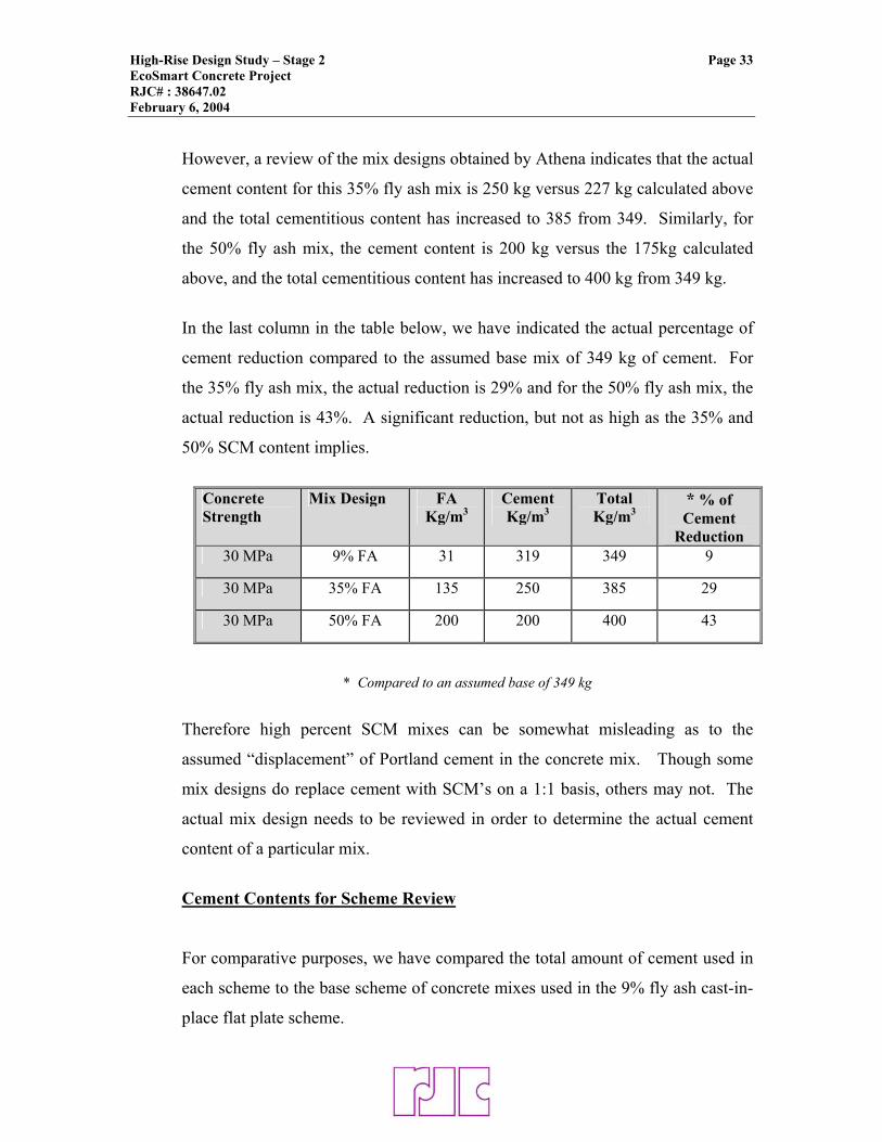
For example, based on the mix designs used by Athena (see table below), their
standard 30MPa concrete mix with 9% SCM’s would contain 319 kg of cement
and 349 kg of total cementitious material. Therefore, for a mix with no fly ash,
one would assume a total cement content of approximately 349 kg or less, and a
35% fly ash mix should contain 227 kg of cement (65% of 349 kg), and a 50% fly
ash mix should contain 175 kg of cement (50% of 349 kg).
High-Rise Design Study – Stage 2 Page 33 EcoSmart Concrete Project RJC# : 38647.02 February 6, 2004
However, a review of the mix designs obtained by Athena indicates that the actual
cement content for this 35% fly ash mix is 250 kg versus 227 kg calculated above
and the total cementitious content has increased to 385 from 349. Similarly, for
the 50% fly ash mix, the cement content is 200 kg versus the 175kg calculated
above, and the total cementitious content has increased to 400 kg from 349 kg.
In the last column in the table below, we have indicated the actual percentage of
cement reduction compared to the assumed base mix of 349 kg of cement. For
the 35% fly ash mix, the actual reduction is 29% and for the 50% fly ash mix, the
actual reduction is 43%. A significant reduction, but not as high as the 35% and
50% SCM content implies.
Concrete Strength
Mix Design FA Kg/m3
Cement Kg/m3
Total Kg/m3
* % of Cement
Reduction 30 MPa 9% FA 31 319 349 9
30 MPa 35% FA 135 250 385 29
30 MPa 50% FA 200 200 400 43
* Compared to an assumed base of 349 kg
Therefore high percent SCM mixes can be somewhat misleading as to the
assumed “displacement” of Portland cement in the concrete mix. Though some
mix designs do replace cement with SCM’s on a 1:1 basis, others may not. The
actual mix design needs to be reviewed in order to determine the actual cement
content of a particular mix.
Cement Contents for Scheme Review
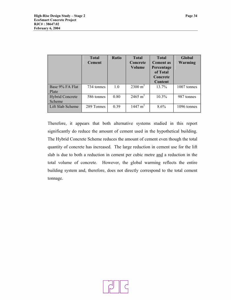
For comparative purposes, we have compared the total amount of cement used in
each scheme to the base scheme of concrete mixes used in the 9% fly ash cast-in-
place flat plate scheme.
High-Rise Design Study – Stage 2 Page 34 EcoSmart Concrete Project RJC# : 38647.02 February 6, 2004
Total Cement
Ratio Total Concrete Volume
Total Cement as Percentage
of Total Concrete Content
Global Warming
Base 9% FA Flat Plate
734 tonnes 1.0 2300 m3 13.7% 1007 tonnes
Hybrid Concrete Scheme
586 tonnes 0.80 2465 m3 10.3% 987 tonnes
Lift Slab Scheme 289 Tonnes 0.39 1447 m3 8.6% 1096 tonnes
Therefore, it appears that both alternative systems studied in this report
significantly do reduce the amount of cement used in the hypothetical building.
The Hybrid Concrete Scheme reduces the amount of cement even though the total
quantity of concrete has increased. The large reduction in cement use for the lift
slab is due to both a reduction in cement per cubic metre and a reduction in the
total volume of concrete. However, the global warming reflects the entire
building system and, therefore, does not directly correspond to the total cement
tonnage.
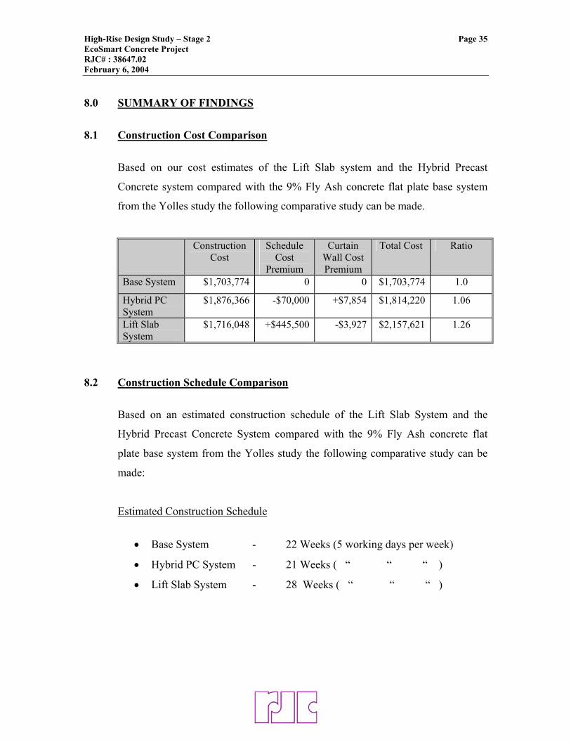
High-Rise Design Study – Stage 2 Page 35 EcoSmart Concrete Project RJC# : 38647.02 February 6, 2004 8.0 SUMMARY OF FINDINGS
8.1 Construction Cost Comparison
Based on our cost estimates of the Lift Slab system and the Hybrid Precast
Concrete system compared with the 9% Fly Ash concrete flat plate base system
from the Yolles study the following comparative study can be made.
Construction Cost
Schedule Cost
Premium
Curtain Wall Cost Premium
Total Cost Ratio
Base System $1,703,774 0 0 $1,703,774 1.0
Hybrid PC System
$1,876,366 -$70,000 +$7,854 $1,814,220 1.06
Lift Slab System
$1,716,048 +$445,500 -$3,927 $2,157,621 1.26
8.2 Construction Schedule Comparison
Based on an estimated construction schedule of the Lift Slab System and the
Hybrid Precast Concrete System compared with the 9% Fly Ash concrete flat
plate base system from the Yolles study the following comparative study can be
made:
Estimated Construction Schedule
• Base System - 22 Weeks (5 working days per week)
• Hybrid PC System - 21 Weeks ( “ “ “ )
• Lift Slab System - 28 Weeks ( “ “ “ )
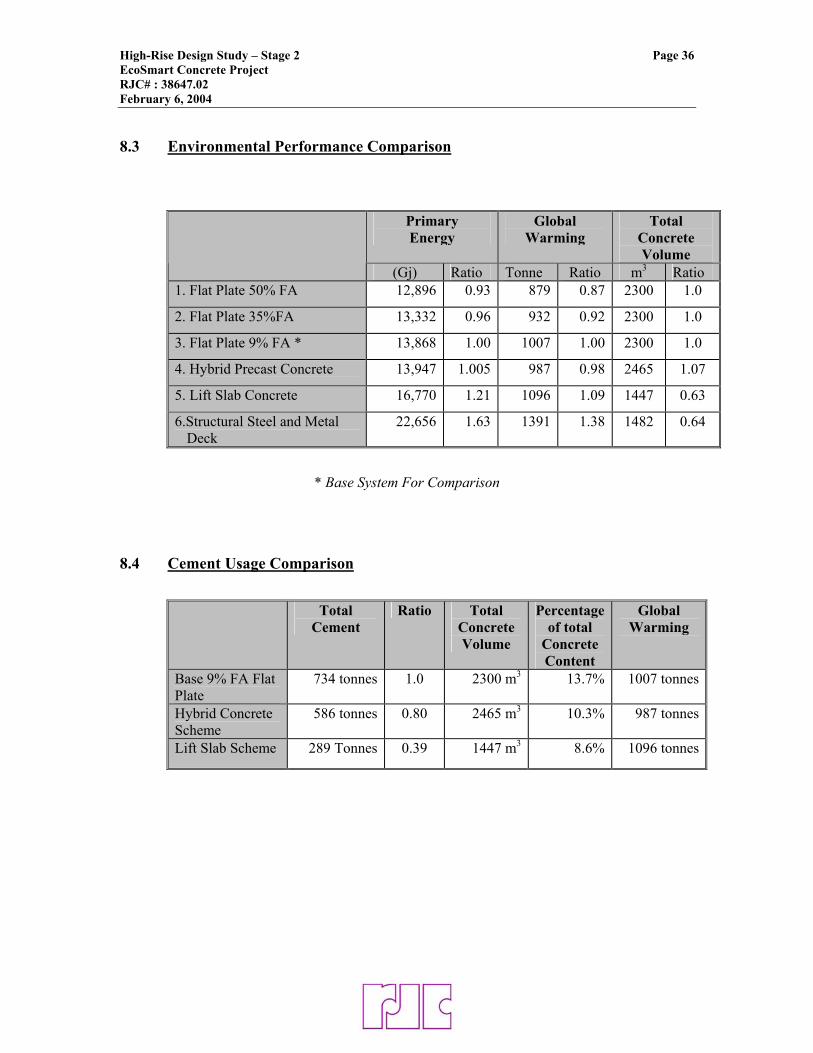
High-Rise Design Study – Stage 2 Page 36 EcoSmart Concrete Project RJC# : 38647.02 February 6, 2004 8.3 Environmental Performance Comparison
Primary Energy
Global Warming
Total Concrete Volume
(Gj) Ratio Tonne Ratio m3 Ratio 1. Flat Plate 50% FA 12,896 0.93 879 0.87 2300 1.0
2. Flat Plate 35%FA 13,332 0.96 932 0.92 2300 1.0
3. Flat Plate 9% FA * 13,868 1.00 1007 1.00 2300 1.0
4. Hybrid Precast Concrete 13,947 1.005 987 0.98 2465 1.07
5. Lift Slab Concrete 16,770 1.21 1096 1.09 1447 0.63
6.Structural Steel and Metal Deck
22,656 1.63 1391 1.38 1482 0.64
* Base System For Comparison
8.4 Cement Usage Comparison
Total
Cement Ratio Total
Concrete Volume
Percentage of total
Concrete Content
Global Warming
Base 9% FA Flat Plate
734 tonnes 1.0 2300 m3 13.7% 1007 tonnes
Hybrid Concrete Scheme
586 tonnes 0.80 2465 m3 10.3% 987 tonnes
Lift Slab Scheme 289 Tonnes 0.39 1447 m3 8.6% 1096 tonnes
APPENDIX A
LIFT SLAB FLOOR PLATE AND CONSTRUCTIVE
SEQUENCE
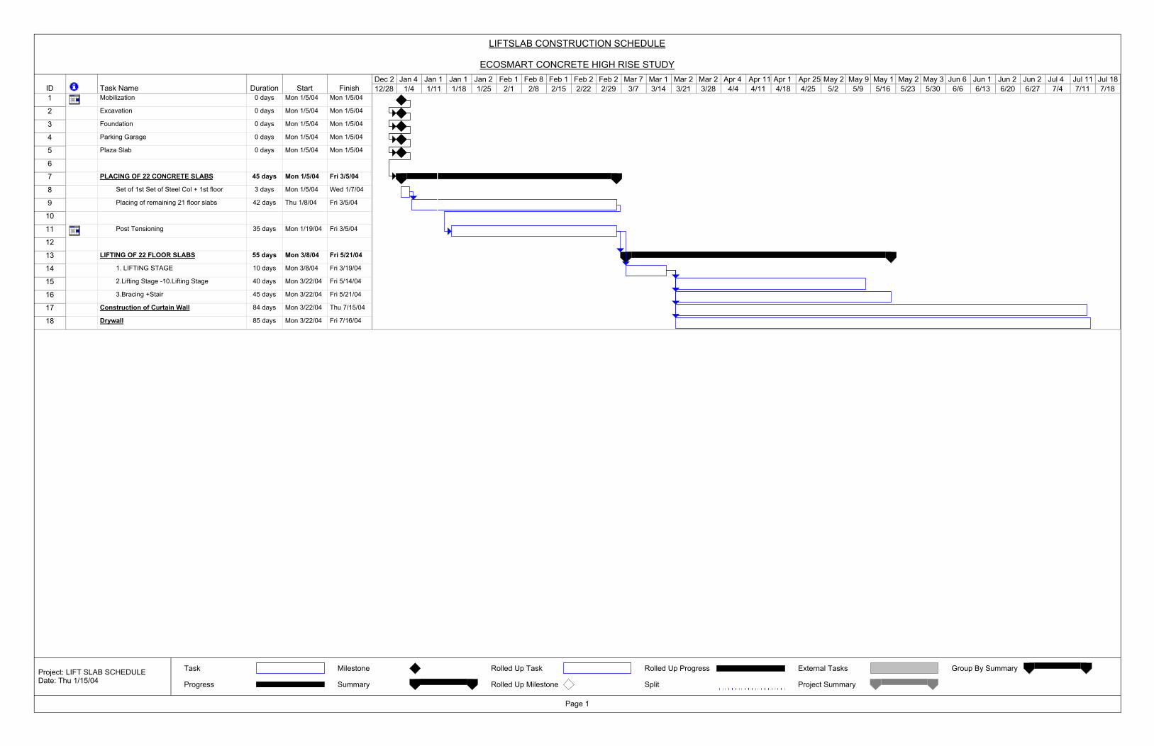
ID Task Name Duration Start Finish1 Mobilization 0 days Mon 1/5/04 Mon 1/5/04
2 Excavation 0 days Mon 1/5/04 Mon 1/5/04
3 Foundation 0 days Mon 1/5/04 Mon 1/5/04
4 Parking Garage 0 days Mon 1/5/04 Mon 1/5/04
5 Plaza Slab 0 days Mon 1/5/04 Mon 1/5/04
6
7 PLACING OF 22 CONCRETE SLABS 45 days Mon 1/5/04 Fri 3/5/04
8 Set of 1st Set of Steel Col + 1st floor 3 days Mon 1/5/04 Wed 1/7/04
9 Placing of remaining 21 floor slabs 42 days Thu 1/8/04 Fri 3/5/04
10
11 Post Tensioning 35 days Mon 1/19/04 Fri 3/5/04
12
13 LIFTING OF 22 FLOOR SLABS 55 days Mon 3/8/04 Fri 5/21/04
14 1. LIFTING STAGE 10 days Mon 3/8/04 Fri 3/19/04
15 2.Lifting Stage -10.Lifting Stage 40 days Mon 3/22/04 Fri 5/14/04
16 3.Bracing +Stair 45 days Mon 3/22/04 Fri 5/21/04
17 Construction of Curtain Wall 84 days Mon 3/22/04 Thu 7/15/04
18 Drywall 85 days Mon 3/22/04 Fri 7/16/04
12/28 1/4 1/11 1/18 1/25 2/1 2/8 2/15 2/22 2/29 3/7 3/14 3/21 3/28 4/4 4/11 4/18 4/25 5/2 5/9 5/16 5/23 5/30 6/6 6/13 6/20 6/27 7/4 7/11 7/18Dec 2 Jan 4 Jan 1 Jan 1 Jan 2 Feb 1 Feb 8 Feb 1 Feb 2 Feb 2 Mar 7 Mar 1 Mar 2 Mar 2 Apr 4 Apr 11 Apr 1 Apr 25 May 2 May 9 May 1 May 2 May 3 Jun 6 Jun 1 Jun 2 Jun 2 Jul 4 Jul 11 Jul 18
Task
Progress
Milestone
Summary
Rolled Up Task
Rolled Up Milestone
Rolled Up Progress
Split
External Tasks
Project Summary
Group By Summary
LIFTSLAB CONSTRUCTION SCHEDULE
ECOSMART CONCRETE HIGH RISE STUDY
Page 1
Project: LIFT SLAB SCHEDULEDate: Thu 1/15/04
APPENDIX B
HYBRID CONCRETE SLAB FLOOR PLATE AND
DETAILS
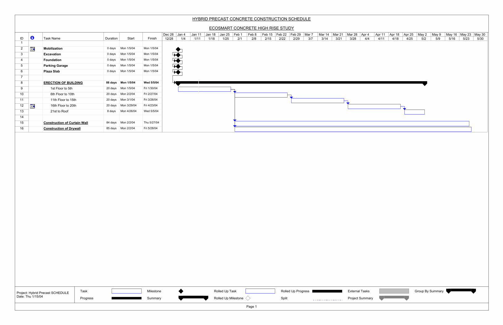
ID Task Name Duration Start Finish1
2 Mobilization 0 days Mon 1/5/04 Mon 1/5/04
3 Excavation 0 days Mon 1/5/04 Mon 1/5/04
4 Foundation 0 days Mon 1/5/04 Mon 1/5/04
5 Parking Garage 0 days Mon 1/5/04 Mon 1/5/04
6 Plaza Slab 0 days Mon 1/5/04 Mon 1/5/04
7
8 ERECTION OF BUILDING 88 days Mon 1/5/04 Wed 5/5/04
9 1st Floor to 5th 20 days Mon 1/5/04 Fri 1/30/04
10 6th Floor to 10th 20 days Mon 2/2/04 Fri 2/27/04
11 11th Floor to 15th 20 days Mon 3/1/04 Fri 3/26/04
12 16th Floor to 20th 20 days Mon 3/29/04 Fri 4/23/04
13 21st to Roof 8 days Mon 4/26/04 Wed 5/5/04
14
15 Construction of Curtain Wall 84 days Mon 2/2/04 Thu 5/27/04
16 Construction of Drywall 85 days Mon 2/2/04 Fri 5/28/04
12/28 1/4 1/11 1/18 1/25 2/1 2/8 2/15 2/22 2/29 3/7 3/14 3/21 3/28 4/4 4/11 4/18 4/25 5/2 5/9 5/16 5/23 5/30Dec 28 Jan 4 Jan 11 Jan 18 Jan 25 Feb 1 Feb 8 Feb 15 Feb 22 Feb 29 Mar 7 Mar 14 Mar 21 Mar 28 Apr 4 Apr 11 Apr 18 Apr 25 May 2 May 9 May 16 May 23 May 30
Task
Progress
Milestone
Summary
Rolled Up Task
Rolled Up Milestone
Rolled Up Progress
Split
External Tasks
Project Summary
Group By Summary
HYBRID PRECAST CONCRETE CONSTRUCTION SCHEDULE
ECOSMART CONCRETE HIGH RISE STUDY
Page 1
Project: Hybrid Precast SCHEDULEDate: Thu 1/15/04
APPENDIX E
YOLLES CAST-IN-PLACE FLAT PLATE BASE SYSTEM
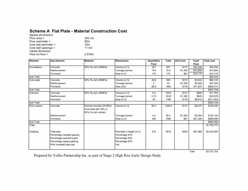
Scheme A Flat Plate - Material Construction CostAgreed dimensionsFloor area = 345 m2Floor perimeter = 85mCore wall perimeter = 33mCore wall openings = 11 m2Varied dimensionFloor to Floor = 2.575m
Element Sub-element Material Dimensions Quantities/ Total Unit Cost Cost/ Total costFloor Floor
Foundations Concrete 50% Fly Ash (30MPa) Volume (m 3) 257 257 $137 $35,209 $35,209Reinforcement Tonnage (tonne) 10.5 10.5 $1,300 $13,650 $13,650Formwork Area (m 2) 175 175 $81 $14,175 $14,175
Sub-Total $63,034Core walls Concrete 50% Fly Ash (30MPa) Volume (m 3) 26.6 585 $137 $3,644 $80,145
Reinforcement Tonnage (tonne) 2 44 $1,300 $2,600 $57,200Formwork Area (m2) 66.5 1463 $178 $11,837 $260,414
Sub-Total $397,759Columns Concrete 50% Fly Ash (30MPa) Volume (m 3) 5.9 129.8 $137 $808 $17,783
Reinforcement Tonnage (tonne) 0.73 16.06 $1,300 $949 $20,878Formwork Area (m 2) 54 1188 $178 $9,612 $211,464
Sub-Total $250,125Floor system Concrete Normal concrete (30 MPa) Volume (m 3) 60.4 1328.8 $137 $8,275 $182,046
(Concrete with 35% or50% Fly Ash similar)
Reinforcement Tonnage (tonne) 4.2 92.4 $1,300 $5,460 $120,120Formwork Area (m 2) 345 7590 $91 $31,395 $690,690
Sub-Total $992,856Total $1,703,773
Cladding Total area Perimeter x Height (m 2) 219 4818 $420 $91,980 $2,023,560Percentage viewable glazing Percentage 40%Percentage spandrel panel Percentage 40%Percentage opaque glazing Percentage 20%With insulated back pan Yes
Total $3,727,333
Prepared by Yolles Partnership Inc. as part of Stage 2 High Rise Early Design Study