Embed Size (px)
Citation preview
WELDING HELMET INSTRUCTIONS
Part #20520
2 Eastwood Technical Assistance: 800.544.5118 >> [email protected]
EASTWOOD WELDING HELMETS are specifically designed to provide maximum eye and face protection from harmful UV and IR radiation emitted when welding, in a lightweight, comfortable housing. Auto-Darkening powered by solar cells and lithium-ion battery provide long, reliable life. Meets ANSI Z-87.1 safety standards.
DANGER indicates a hazardous situation which, if not avoided, will result in death or serious injury.
WARNING indicates a hazardous situation which, if not avoided, could result in death or serious injury.
CAUTION used with the safety alert symbol, indicates a hazardous situation which, if not avoided, could result in minor or moderate injury.
NOTICE is used to address practices not related to personal injury.
SAFETY INFORMATIONThe following explanations are displayed in this manual, on the labeling, and on all other information provided with this product:
READ AND UNDERSTAND INSTRUCTIONS COMPLETELY!• Eastwood welding helmets are designed to protect the user’s eyes and
face from harmful radiation, sparks and spatter under normal welding conditions. They are not intended to offer protection against impact hazards, explosions or corrosive liquids.
• Wear appropriate eye protection under helmet to provide impact protection.
• Always test Auto-Darkening feature before each use by quickly subjecting the face of the Welding Helmet to sunlight or other bright light source. If the Auto-Darkening feature fails to function, permanent eye damage can occur from exposure to welding flash and radiation. DO NOT USE.
• The operating temperature range of the Auto-Darkening feature is 23°F to 130°F (-5°C to 55°C). The response time may be affected beyond the described temperatures causing an unsafe condition. DO NOT USE beyond recommended operating temperature range.

To order parts and supplies: 800.345.1178 >> eastwood.com 3
ELECTRIC SHOCK HAZARD!• Improper use of an electric welder and associated equipment can cause
electric shock, injury and death! Read all precautions described in the specific Welder Manual to reduce the possibility of electric shock.
• The electrode and work (or ground) circuits are electrically “hot” when the welder is on. Do not allow these “hot” parts or associated equipment to come in contact with your bare skin or wet clothing.
• Separate yourself from the welding circuit by using insulating mats, protective clothing, leather welding gloves and insulated footwear to avoid being part of the welding circuit.
• Be sure that the work piece is properly supported and grounded prior to beginning an electric welding operation.
• Always attach the ground clamp to the piece to be welded and as close to the weld area as possible. This will give the least resistance and best weld.
• Always wear dry, protective clothing and leather welding gloves and insulated footwear. Use suitable clothing made from durable flame-resistant material to protect your skin.
• If other persons or pets are in the area of welding, use welding screens to protect bystanders from sparks and harmful arc rays.
• Always weld in a clean, dry, well ventilated area. Do not operate a welder in humid, wet, rainy or poorly ventilated areas.
EYE INJURY HAZARD!• Inadequate levels of arc ray shading can cause permanent eye injury.
This helmet is capable of protection up to shade level 11 only. If your par-ticular welding process emits arc radiation at levels higher than 11, DO NOT USE this helmet and seek alternate protection.
Consult the chart on the next page to verify that this helmet provides adequate protection before using.
SAFETY INFORMATION
4 Eastwood Technical Assistance: 800.544.5118 >> [email protected]
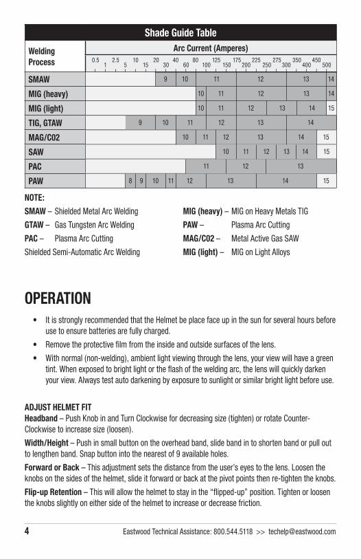
Shade Guide Table
WeldingProcess
Arc Current (Amperes)
SMAW
MIG (heavy)
MIG (light)
TIG, GTAW
MAG/C02
SAW
PAC
PAW
0.5 2.5 10 20 40 80 125 175 225 275 350 4501 5 15 30 60 100 150 200 250 300 400 500
9 10 11 12 13 14
10 11 12 13 14
10 11 12 13 14 15
9 10 11 12 13 14
10 11 12 13 14 15
10 11 12 13 14 15
11 12 13
8 9 10 11 12 13 14 15
NOTE:
SMAW – Shielded Metal Arc Welding
GTAW – Gas Tungsten Arc Welding
PAC – Plasma Arc Cutting
Shielded Semi-Automatic Arc Welding
MIG (heavy) – MIG on Heavy Metals TIG
PAW – Plasma Arc Cutting
MAG/C02 – Metal Active Gas SAW
MIG (light) – MIG on Light Alloys
OPERATION• It is strongly recommended that the Helmet be place face up in the sun for several hours before
use to ensure batteries are fully charged.
• Remove the protective fi lm from the inside and outside surfaces of the lens.
• With normal (non-welding), ambient light viewing through the lens, your view will have a green tint. When exposed to bright light or the fl ash of the welding arc, the lens will quickly darken your view. Always test auto darkening by exposure to sunlight or similar bright light before use.
ADJUST HELMET FITHeadband – Push Knob in and Turn Clockwise for decreasing size (tighten) or rotate Counter-Clockwise to increase size (loosen).
Width/Height – Push in small button on the overhead band, slide band in to shorten band or pull out to lengthen band. Snap button into the nearest of 9 available holes.
Forward or Back – This adjustment sets the distance from the user’s eyes to the lens. Loosen the knobs on the sides of the helmet, slide it forward or back at the pivot points then re-tighten the knobs.
Flip-up Retention – This will allow the helmet to stay in the “fl ipped-up” position. Tighten or loosen the knobs slightly on either side of the helmet to increase or decrease friction.

To order parts and supplies: 800.345.1178 >> eastwood.com 5
REPLACING SHADE CARTRIDGE AND/OR CLEAR FRONT COVER LENS1. Grasp the two semi-cylindrical
retaining latches and slide them inward toward one another (FIG 1).
2. Rotate the Shade Cartridge up and out of the Helmet shell.
3. Remove Clear Front Cover Lens.
4. Replace Clear Front Cover Lens.
5. Place tabs of Shade Cartridge under pockets.
6. Rotate the Shade Cartridge back into place.
7. Move semi-cylindrical latches outward to latch.
MAINTENANCE• Clean outside and inside of lens with a soft cloth and small amount of glass cleaner.
NOTE: Do not use excessive glass cleaner or allow the lens assembly to become wet or the sensitive electronics will be destroyed. Never use solvents.
• Clean headband with a cloth dampened with mild soap and water. Allow to dry thoroughly.
• Check lens assembly for damage before each use. If cracked or broken, DO NOT USE.
FIG. 1
��✓�������✓����� ��✓�������✓�����

6 Eastwood Technical Assistance: 800.544.5118 >> [email protected]
To order parts and supplies: 800.345.1178 >> eastwood.com 7
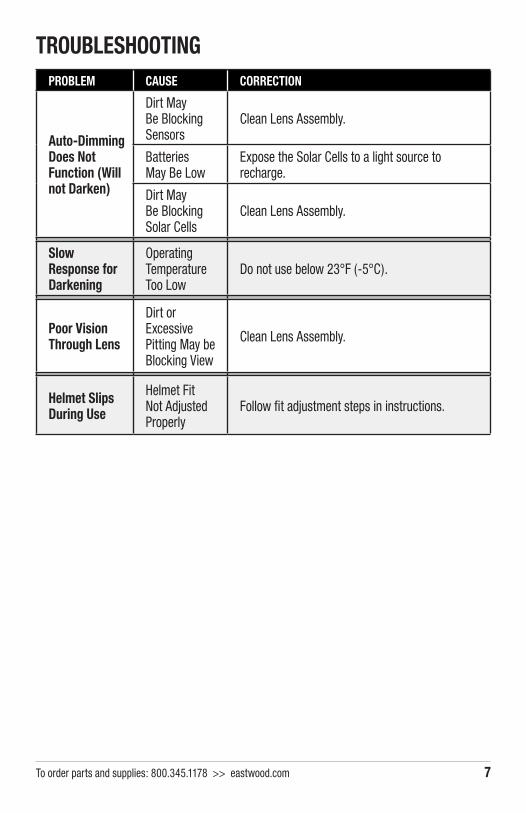
PROBLEM CAUSE CORRECTION
Auto-Dimming Does Not Function (Will not Darken)
Dirt May Be Blocking Sensors
Clean Lens Assembly.
Batteries May Be Low
Expose the Solar Cells to a light source to recharge.
Dirt May Be Blocking Solar Cells
Clean Lens Assembly.
Slow Response for Darkening
Operating Temperature Too Low
Do not use below 23°F (-5°C).
Poor Vision Through Lens
Dirt or Excessive Pitting May be Blocking View
Clean Lens Assembly.
Helmet Slips During Use
Helmet Fit Not Adjusted Properly
Follow fit adjustment steps in instructions.
TROUBLESHOOTING

© Copyright 2016 Easthill Group, Inc. 6/16 Instruction item #20520Q Rev 0
If you have any questions about the use of this product, please contact The Eastwood Technical Assistance Service Department: 800.544.5118 >> email: [email protected]
PDF version of this manual is available online >> eastwood.com/20520manualThe Eastwood Company 263 Shoemaker Road, Pottstown, PA 19464, USA
US and Canada: 800.345.1178 Outside US: 610.718.8335 Fax: 610.323.6268 eastwood.com
ADDITIONAL ITEMS#20525 Replacement Outer Lens