Embed Size (px)
Citation preview

EVS28 International Electric Vehicle Symposium and Exhibition 1
EVS28
KINTEX, Korea, May 3-6, 2015
Real-time optimal energy management strategy for range-
extended electric bus in Harbin urban bus driving cycle
Jingfu Chen1, 2, Junfeng Wu2, Jiuyu Du1*
1State Key Laboratory of Automotive Safety and Energy, Tsinghua University, Beijing, 100084, China,
[email protected] 2 Department of Automation, Harbin University of Science and Technology, Harbin, China
Abstract
Developing electric driving powertrain technology is the core of national strategies for Chinese electric
vehicles. Range-extended electric vehicles, an important configuration, are focused by more and more
automobile manufacturers and consumers. The energy management strategy is a key technology to develop
range-extended electric vehicles. DP strategy can achieve the optimal energy management. However, it
cannot be used in the real-time as the heavy computational burden. This paper establishes the simulation
model of the range-extended electric bus which is developed independently by Tsinghua University. The
model is simulated using the DP control strategy in the Harbin urban bus driving cycle. Minimum energy
consumption is regarded as the optimization target. According to the simulation result, δSOC control
strategy is put forward on the basis of the relationship between the SOC change per second and the motor
power. This strategy can guarantee the fuel saving rate and be applied in the real time simultaneously. The
simulation results show that when the range-extended electric bus runs 189km in the Harbin urban driving
cycles, the fuel saving rate can exceed 30% with DP and δSOC strategies. The energy consumption
difference between these control strategies is no more than 2%, but the δSOC strategy improves the
computational efficiency significantly.
Keywords: DP strategy, Energy management strategy, Range-Extended Electric Bus; Real-time control
1 Introduction The transport sector, a major oil consumer and
greenhouse gas emitter, accounted for 26% of the
world’s energy use and 23% of the energy-related
greenhouse gas emissions (GHG) in 2004. Road
transportation is responsible for over 90% of these
emissions [1] [2]. To overcome the resulting air
pollution and energy crisis, governments are
encouraging automobile manufacturers to develop
electric vehicles (EVs) and hybrid electric vehicles (HEVs). However, the battery cycle life
and the travel range of such vehicles continue to
hinder their development. Therefore, for now,
range-extended electric vehicles seem to be the
most promising among renewable energy vehicles
[3].
Given that the energy required by range-extended
electric vehicles is supplied mainly by range
extenders and the electric power grid, optimal
strategies should be applied to such vehicles’
energy management systems to minimize their
energy consumption [4]. At present, these optimal
strategies can be classified into three categories
EVS28 International Electric Vehicle Symposium and Exhibition 2
[5]: ruled-based strategies, modern control
theory–based intelligent strategies, and optimal
strategies. He et al. [6] presented several rule-
based control strategies such as constant-voltage
control, out-line control, and on-line control. Wei
et al. [7] devised a model-based fuel optimal
control for HEVs. The rule-based control strategy
is easy to understand and realize. However, it
lacks any rigorous mathematical basis, and it
cannot extract the full performance potential of a
hybrid system [8]. Schouten et al. [9] and Gong et
al. [10] designed control rules for energy
management systems by using fuzzy logic and
neural network. The methods achieved better
results than the traditional rule-based control
strategy, but its results still have difference to
those achieved with the optimal strategies. The
dynamic programming (DP) algorithm is widely
used in the optimal strategies. DP is one of the
best methods for dealing with constrained non-
linear optimal problems [11]. It is suitable for
optimizing the control strategy of an energy
management system when the driving cycle is
known in advance. Geng et al. [12] and Barsali et
al. [13] presented an equivalent consumption
minimization strategy based on the DP algorithm.
However, this strategy cannot be applied to real-
time control because of its heavy computational
burden. Given that the rule-based control strategy
can be applied easily to real-time control, the DP
algorithm can be combined with the rule-based
control strategy. The resulting hybrid control
strategy would not only have the global optimal
feature of DP strategy but would also be easily
applicable to real-time control. He et al. [14] used
an optimal control strategy for a specified driving
cycle to control long-distance driving cycle for a
plug-in series–parallel hybrid electric bus. The
strategy reduces the computational time
significantly, while maintaining the desired
precision. Chen et al. [15] designed a DP
algorithm–based energy management strategy for
range-extended electric vehicles. Then, a rule-
based control strategy was designed considering
the global optimal solution and driving cycle
recognition. Peng et al. [16] considered energy
consumption and GHG emissions to design an
energy management strategy by using the DP
algorithm and presented an adaptive rule-based
control strategy based on the DP solution. Bianchi
et al. [17] established a rule-based control strategy
for HEVs by using the DP strategy. The
corresponding simulation result was close to the
optimal result.
We present a DP and rule-based hybrid control
strategy for a range-extended electric bus (REEB)
running the Chinese typical urban bus driving
cycle. This strategy retains the advantages of the
DP and the rule-based strategies, while reducing
the computational burden.
Engine Generator Rectifier
Mechanical
Joint
Range-Extender
Power
battery
Traction Motor
ControllerTraction Motor
Mechanical
Joint
Transmission and
Final Drive
Electrical
Joint
Electrical
Joint
Electrical
Joint
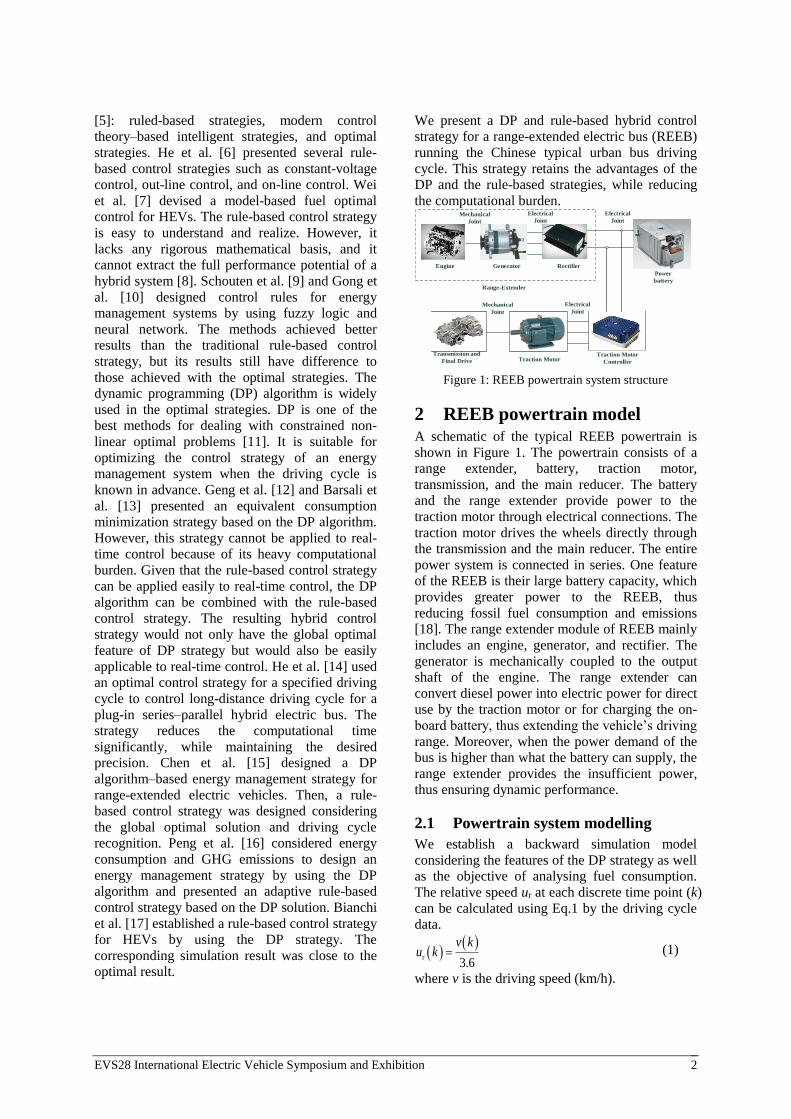
Figure 1: REEB powertrain system structure
2 REEB powertrain model A schematic of the typical REEB powertrain is
shown in Figure 1. The powertrain consists of a
range extender, battery, traction motor,
transmission, and the main reducer. The battery
and the range extender provide power to the
traction motor through electrical connections. The
traction motor drives the wheels directly through
the transmission and the main reducer. The entire
power system is connected in series. One feature
of the REEB is their large battery capacity, which
provides greater power to the REEB, thus
reducing fossil fuel consumption and emissions
[18]. The range extender module of REEB mainly
includes an engine, generator, and rectifier. The
generator is mechanically coupled to the output
shaft of the engine. The range extender can
convert diesel power into electric power for direct
use by the traction motor or for charging the on-
board battery, thus extending the vehicle’s driving
range. Moreover, when the power demand of the
bus is higher than what the battery can supply, the
range extender provides the insufficient power,
thus ensuring dynamic performance.
2.1 Powertrain system modelling
We establish a backward simulation model
considering the features of the DP strategy as well
as the objective of analysing fuel consumption.
The relative speed ur at each discrete time point (k)
can be calculated using Eq.1 by the driving cycle
data.
r3.6
v ku k (1)
where v is the driving speed (km/h).
EVS28 International Electric Vehicle Symposium and Exhibition 3
To fulfil the requirements of the DP strategy, the
vehicle’s longitudinal dynamics model is
expressed as the following state equation:
req T
r
v
1000 ( )1( ) (
( ) ( )p r
P ku k
m m u k
rf w r i
r
( )( )
( )
u kF F u k F
u k (2)
where δ is the conversion coefficient of the
vehicle rotation quality, mv is the bus mass, mp is
the passenger mass, Preq is the demand power of
the transmission, ηT is the efficiency of the
transmission and the main reducer, Ff is the
rolling resistance, Fw is the air resistance and the
function of ur, and Fi is the slope resistance. The
parameters of the REEB are shown in Table 1.
The drive power of the vehicle Pmotor is provided
by the battery Pbat and/or the range extender Pre,
as expressed by Eq. 3.
req
motor re bat
motor
PP P P
(3)
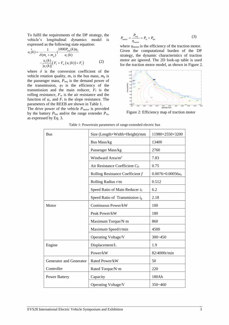
where ηmotor is the efficiency of the traction motor.
Given the computational burden of the DP
strategy, the dynamic characteristics of traction
motor are ignored. The 2D look-up table is used
for the traction motor model, as shown in Figure 2.
0.714
0.714
0.728
0.728
0.742
0.742
0.756
0.756
0.771
0.771
0.785
0.785
0.785
0.799
0.799
0.799
0.813
0.813 0.813
0.827
0.841
0.855
0.869
0.869
0.884
0.898
0.912
speed(r/min)
torq
ue
(Nm
)
500 1000 1500 2000 2500 3000 3500 4000 4500 5000 5500 6000
100
200
300
400
500
600
700
800
900
1000
1100
Figure 2: Efficiency map of traction motor
Table 1: Powertrain parameters of range-extended electric bus
Bus Size (Length×Width×Height)/mm 11980×2550×3200
Bus Mass/kg 13400
Passenger Mass/kg 2760
Windward Area/m2 7.83
Air Resistance Coefficient CD 0.75
Rolling Resistance Coefficient f 0.0076+0.00056ua
Rolling Radius r/m 0.512
Speed Ratio of Main Reducer i0 6.2
Speed Ratio of Transmission ig 2.18
Motor Continuous Power/kW 100
Peak Power/kW 180
Maximum Torque/N·m 860
Maximum Speed/r/min 4500
Operating Voltage/V 300~450
Engine Displacement/L 1.9
Power/kW 82/4000r/min
Generator and Generator
Controller
Rated Power/kW 50
Rated Torque/N·m 220
Power Battery Capacity 180Ah
Operating Voltage/V 350~460

EVS28 International Electric Vehicle Symposium and Exhibition 4
Generally, the equivalent battery models include
Rint, PNGV, and GNL. The Rint model focuses
on the charge/discharge resistance and the open
circuit voltage of the battery, and it has a simple
structure. What is more, it meets the demand of
the DP strategy. Considering the features of the
DP strategy, the following form of the state
equation is used in the battery model [19].
bat
( )I kSOC
Q
(4)
SOC OCV( ( )U SOCSOC
2
int( ( ) 4( ( ) )OCV tU SOC R SOC R
1/2
motor re( ( ) ( ))) )P k P k 1
int t bat(2( ( ) ) )R SOC R Q (5)
where I is the battery current, Qbat is the battery
capacity, ηSOC is the Coulomb efficiency, UOCV is
the open circuit voltage of the battery, Rint and Rt
are the internal resistance and thermal resistance,
respectively. Rint and UOCV are functions of the
SOC. The equivalent circuit of the simplified
battery model is shown in Figure 3.
Rint Rt
Uvoc
ib
Figure 3: Equivalent circuit of simplified battery
model
As in [20], the charging ηchg and discharging ηdis
efficiencies are calculated using Eq. 6.
ocv dis dis batdis 2
ocv ocv
411 1 ,
2
U IR R P
U U
motor re 0P k P k
chg batocvchg 2
ocv chg ocv
42 / 1 1 ,
R PU
U IR U
motor re 0P k P k (6)
where Rdis and Rchg are the discharging resistance
and the charging resistance, respectively.
The dynamic characteristics of the engine and
generator models in the range extender are also
ignored to reduce the computational burden of
the DP strategy. Their models are the MAPs,
which are generated by using the data from the
bench tests. Because the generator is
mechanically coupled to the output shaft of the engine, the generator and engine are in the same
working points. The optimal fuel economy curve
of the range extender is developed by the method
described in [15], as shown in Figures 4 and 5.
7.66
7.66
15.3
15.3
23
23
30.6
30.6
38.3
38.3
45.9
45.9
53.6
53.6
61.3
61.3
68.9
68.9
76.6
76.6
84.2
84.2
91.9
91.9
99.5
99.5
107
107
115
115
123
123
130
130
138
138
145
145
153
153
161
161
168
168
176
176
184
184
191
191
199
199
207
207
214
214
214
222
222
230
230
230
230
237
237
237
245
245
245
245
253
253
260
260
268
268
276
276
283
283
291
299
306
314
322
329
337
345
352
360
368
375
383
390
398
406
413
421429 429
436
444
452
459
467
475
482
490
498
505
513521
528536
544551
559567574582590597605613
5kw
10kw
15kw
20kw
25kw
30kw
35kw40kw
45kw50kw
55kw
Engine Speed(rpm)
En
gin
e T
orq
ue
(Nm
)
1000 1500 2000 2500 3000 3500 400020
40
60
80
100
120
140
160
180
200
220
240
Figure 4: BSFC map of engine
0.4130.425 0.4380.451 0.4630.476 0.4890.502
0.5140.527
0.54
0.552
0.565
0.578
0.59
0.603
0.616
0.628
0.641
0.654
0.666
0.679
0.692
0.705
0.717
0.73
0.743
0.755
0.768
0.781
0.793
0.806
0.819
0.831
0.844
0.857
0.869
0.869
0.869
0.882
0.882
0.882
0.882
0.895
0.895
0.895
0.895
0.908
0.908
0.908
0.908
0.908
5kw
10kw
15kw
20kw
25kw
30kw35kw
40kw45kw
50kw55kw
Generator Speed(rpm)
Ge
ne
tato
r T
orq
ue
(Nm
)
1400 1600 1800 2000 2200 2400 2600 2800 3000 3200
20
40
60
80
100
120
140
160
180
200
220
Figure 5: Efficiency map of generator
3 Driving cycle As driving cycles are an important factor to affect
the energy consumption of electric vehicles, this
paper conducts the simulation on the basis of the
Harbin urban bus driving cycle, as shown in Figure
5. Considering investigation results on typical
cities of electric buses main running lines, the
driving distance is about 200km per day. Therefore,
given the large battery capacity of the REEB and
the one-charge-per-day operation mode, the
driving cycle for the simulation is 20 Harbin urban
bus driving cycles, which spans 189.8km.
0 200 400 600 800 1000 1200 1400 1600 18000
10
20
30
40
50
60
Time(s)
Sp
eed
(km
/h)
Figure 5: Harbin urban bus driving cycle
EVS28 International Electric Vehicle Symposium and Exhibition 5
4 Energy management strategy
4.1 DP strategy
In the horizon [t0,tf], the state variables of the
REEB powertrain system include the SOC of the
battery and the bus speed. As the bus speed can
be determined from the driving cycle, the state
variable is x(t) = [SOC(t)]’. According to the
optimal objective of minimum equivalent fuel
consumption, the range extender is regarded as
the control variable, u(t)=[Pre(t)]. The powertrain
system of the REEB in the discrete form is
shown as follows:
,x f x k u k
(7)
where f represents Eqs. 1–6.
The constraint conditions of the state space are
expressed by Eq. 8.
bat bus,max ocv bus,max chg[ / ,P U U U R
bus,min ocv bus,min dis/ ]U U U R
re re,max0 P P
L HSOC <SOC<SOC
m,min m m,maxT T t T (8)
where Ubus,max, Ubus,min, Uocv, Rchg, and Rdis are
battery parameters that represent the maximum
voltage, minimum voltage, open circuit voltage,
and charging resistance and discharging
resistance, respectively. Pre,max denotes the
maximum power of the range extender. SOCH
and SOCL represent the maximum and minimum
values of the SOC, respectively. Tm denotes the
traction motor torque; Tm,min and Tm,max represent
the maximum torque and the minimum torque of
the traction motor, respectively.
The key to the DP strategy is the reasonable cost
function. In this paper, the electric power is
equivalent to the fuel consumption, and
achieving the minimum fuel consumption is
regarded as the objective for reducing the fuel
consumption and emissions. The cost function J
is shown as follows:
re,k k bat,k
k 0
N
J C k C
(9)
where Cre,k is the fuel consumption of the range
extender in the k-th state, Cbat,k is the equivalent
fuel consumption of the battery in the k-th state,
and kk is the coefficient for constraining the SOC.
The fuel consumption of the range extender,
equivalent fuel consumption of the battery, and
kk can be calculated as follows:
re engC P be t (10)
batsgn re,avg
bat bat dis chg
re,avg
P CC P t
P
(11)
k 1 2 (SOCk
H L H L0.5(SOC SOC )) / (SOC SOC ) (12)
where Peng is the output power of the engine in the
k-th state, be is the specific fuel consumption,
Cre,avg is the average fuel consumption of the range
extender, Pre,avg is the average output power of the
range extender, μ is the balance coefficient
required to maintain the SOC within the
reasonable range [21].
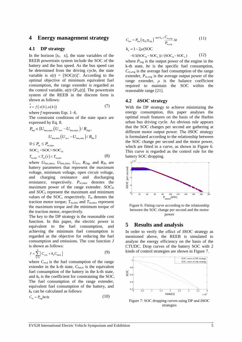
4.2 δSOC strategy
With the DP strategy to achieve minimizing the
energy consumption, this paper analyses the
optimal result features on the basis of the Harbin
urban bus driving cycle. An obvious rule appears
that the SOC changes per second are gathering at
different motor output power. The δSOC strategy
is formulated according to the relationship between
the SOC change per second and the motor power,
which are fitted in a curve, as shown in Figure 6.
This curve is regarded as the control rule for the
battery SOC dropping.
0 20 40 60 80 100 120 140 160 180 200-6
-4
-2
0
2x 10
-4
Pmotor
(kW)
δS
OC
per
sec
on
d
Figure 6: Fitting curve according to the relationship
between the SOC change per second and the motor
power
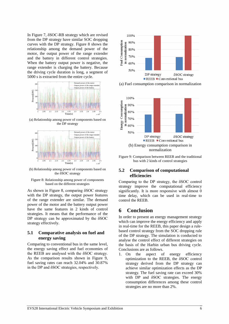
5 Results and analysis In order to verify the effect of δSOC strategy as
mentioned above, the REEB is simulated to
analyse the energy efficiency on the basis of the
CTUDC. Drop curves of the battery SOC with 2
kinds of control strategies are shown in Figure 7.
0 0.5 1 1.5 2 2.5 3 3.5 4
x 104
0.2
0.4
0.6
0.8
1
time(s)
SO
C
SOC curve of DP strategy
SOC curve of rule strategy
Figure 7: SOC dropping curves using DP and δSOC
strategies
EVS28 International Electric Vehicle Symposium and Exhibition 6
In Figure 7, δSOC-RB strategy which are revised
from the DP strategy have similar SOC dropping
curves with the DP strategy. Figure 8 shows the
relationship among the demand power of the
motor, the output power of the range extender
and the battery in different control strategies.
When the battery output power is negative, the
range extender is charging the battery. Because
the driving cycle duration is long, a segment of
5000 s is extracted from the entire cycle.
2 2.05 2.1 2.15 2.2 2.25 2.3 2.35 2.4 2.45 2.5
x 104
0
50
100
150
200
Time(s)
Po
wer
(kW
)
Demand power of the motor
Output power of the range extender
Output power of the battery
(a) Relationship among power of components based on
the DP strategy
2 2.05 2.1 2.15 2.2 2.25 2.3 2.35 2.4 2.45 2.5
x 104
0
50
100
150
200
Time(s)
Po
wer
(kW
)
Demand power of the motor
Output power of the range extender
Output power of the battery
(b) Relationship among power of components based on
the δSOC strategy
Figure 8: Relationship among power of components
based on the different strategies
As shown in Figure 8, comparing δSOC strategy
with the DP strategy, the output power features
of the range extender are similar. The demand
power of the motor and the battery output power
have the same features in 2 kinds of control
strategies. It means that the performance of the
DP strategy can be approximated by the δSOC
strategy effectively.
5.1 Comparative analysis on fuel and
energy saving
Comparing to conventional bus in the same level,
the energy saving effect and fuel economies of
the REEB are analysed with the δSOC strategy.
As the comparison results shown in Figure 9,
fuel saving rates can reach 32.04% and 30.87%
in the DP and δSOC strategies, respectively.
(a) Fuel consumption comparison in normalization
(b) Energy consumption comparison in
normalization
Figure 9: Comparison between REEB and the traditional
bus with 2 kinds of control strategies
5.2 Comparison of computational
efficiencies
Comparing to the DP strategy, the δSOC control
strategy improve the computational efficiency
significantly. It is more responsive with almost 0
time delay, which can be used in real-time to
control the REEB.
6 Conclusion In order to present an energy management strategy
which can improve the energy efficiency and apply
in real-time for the REEB, this paper design a rule-
based control strategy from the SOC dropping rule
of the DP strategy. The simulation is conducted to
analyse the control effect of different strategies on
the basis of the Harbin urban bus driving cycle.
Conclusions are as follows.
1. On the aspect of energy efficiency
optimization to the REEB, the δSOC control
strategy derived from the DP strategy can
achieve similar optimization effects as the DP
strategy. The fuel saving rate can exceed 30%
with DP and δSOC strategies. The energy
consumption differences among these control strategies are no more than 2%.
EVS28 International Electric Vehicle Symposium and Exhibition 7
2. The δSOC strategy not only keep the energy
efficiency of the powertrain, but also
improve the computational efficiency
significantly. It can achieve real-time energy
management for the REEB with 0 time delay
control.
From the analysis shows above, the optimal
performance of the δSOC strategy is in a high
level. Considering the real-time performance, the
δSOC strategy is ideal energy management
strategy for the REEB in this paper.
Acknowledgments This research is funded by MOST (Ministry of
Science and Technology) ‘International S&T
Cooperation Program of China’ under contract of
No. 2014DFG71590 and 2012DFA81190, and
National Science and Technology Infrastructure
Program under contract of No. 2013BAG06B04.
References [1] Ou X, Zhang X, Chang S. Alternative fuel buses
currently in use in China: life-cycle fossil energy
use, GHG emissions and policy
recommendations. Energy Policy, 2010, 38(1):
406-418.
[2] Kammen D M, Arons S M, Lemoine D M, et al.
Cost-effectiveness of greenhouse gas emission
reductions from plug-in hybrid electric
vehicles[J]. Environment, 2002, 7(2): 155-62.
[3] Tate E D, Harpster M O, Savagian P J. The
electrification of the automobile: from
conventional hybrid, to plug-in hybrids, to
extended-range electric vehicles. SAE Technical
Paper, 2008.
[4] Cipek M, Coric M, Skugor B, et al. Dynamic
programming-based optimization of control
variables of an extended range electric vehicle.
SAE 2013 World Congress & Exhibition, 2013.
[5] Vural B, Boynuegri A R, Nakir I, et al. Fuel cell
and ultra-capacitor hybridization: a prototype
test bench–based analysis of different energy
management strategies for vehicular applications.
International Journal of Hydrogen Energy, 2010,
35(20): 11161-11171.
[6] He B, Lu L G, Li J Q. Simulation research on
energy management strategy of fuel cell hybrid
electric vehicle. Journal of Highway and
Transportation Research and Development, 2006,
23(1): 151-154.
[7] Wei X, Guzzella L, Utkin V I, et al. Model-
based fuel optimal control of hybrid electric
vehicle using variable structure control systems.
Journal of Dynamic Systems, Measurement, and
Control, 2007, 129(1): 13-19.
[8] Jalil N, Kheir N A, Salman M. A rule-based
energy management strategy for a series hybrid
vehicle. American Control Conference, 1997
Proceedings of the IEEE, 1997, 1: 689-693.
[9] Schouten N J, Salman M A, Kheir N A. Fuzzy
logic control for parallel hybrid vehicles. Control
Systems Technology, IEEE Transactions on, 2002,
10(3): 460-468.
[10] Gong Q, Li Y, Peng Z. Power management of
plug-in hybrid electric vehicles using neural
network based trip modeling. American Control
Conference, 2009. ACC'09. IEEE, 2009: 4601-
4606.
[11] Koot M, Kessels J T B A, de Jager B, et al. Energy
management strategies for vehicular electric power
systems. Vehicular Technology, IEEE
Transactions on, 2005, 54(3): 771-782.
[12] Geng B, Mills J K, Sun D. Energy management
control of microturbine-powered plug-in hybrid
electric vehicles using the telemetry equivalent
consumption minimization strategy. Vehicular
Technology, IEEE Transactions on, 2011, 60(9):
4238-4248.
[13] Barsali S, Miulli C, Possenti A. A control strategy
to minimize fuel consumption of series hybrid
electric vehicles. Energy Conversion, IEEE
Transactions on, 2004, 19(1): 187-195.
[14] He H, Tang H, Wang X. Global optimal energy
management strategy research for a plug-in series-
parallel hybrid electric bus by using dynamic
programming. Mathematical Problems in
Engineering, 2013.
[15] Chen B C, Wu Y Y, Tsai H C. Design and analysis
of power management strategy for range-extended
electric vehicle using dynamic programming.
Applied Energy, 2014, 113: 1764-1774.
[16] Kum D, Peng H, Bucknor N K. Optimal energy
and catalyst temperature management of plug-in
hybrid electric vehicles for minimum fuel
consumption and tail-pipe emissions. Control
Systems Technology, IEEE Transactions on, 2013,
21(1): 14-26.
[17] Bianchi D, Rolando L, Serrao L, et al. Layered
control strategies for hybrid electric vehicles based
on optimal control. International Journal of
Electric and Hybrid Vehicles, 2011, 3(2): 191-217.
[18] Wu X, Hu C, Chen J. Energy flow chart-based
energy efficiency analysis of a range-extended
electric bus. Mathematical Problems in
Engineering, 2014.
[19] Yuan Z, Teng L, Fengchun S, et al. Comparative
study of dynamic programming and Pontryagin’s
EVS28 International Electric Vehicle Symposium and Exhibition 8
minimum principle on energy management for a
parallel hybrid electric vehicle. Energies, 2013,
6(4): 2305-2318.
[20] Xu L, Ouyang M, Li J, et al. Application of
Pontryagin's minimal principle to the energy
management strategy of plug-in fuel cell electric
vehicles. International Journal of Hydrogen
Energy, 2013, 38(24): 10104-10115.
[21] Xu L. Powertrain system modeling and optimal
control of fuel cell hybrid electric vehicle.
Beijing: Tsinghua University doctoral paper,
2009.
Authors
Jingfu Chen is a graduate student
of Department of Automation,
Harbin University of Science and
Technology. He is a member of
U.S.-China CERC-clean Vehicles
Consortium. His current focuses
are plug-in electric vehicles and
electric vehicle R&D technology
roadmap.
Dr. Jiuyu Du is an assistant
professor of Tsinghua University.
She focuses on advanced vehicle
powertrain design, simulation,
energy-saving and new energy
vehicle system analysis, and
performance analysis and
evaluation of vehicle powertrain,
and electric vehicle R&D
technology roadmap.