Embed Size (px)
Citation preview
18 PHARMACEUTICAL ENGINEERING • MAY/JUNE 2001
The Validation Master Plan
Reasons, Regulations, and Rules:A Guide to the Validation MasterPlan (VMP)
Reasons, Regulations, and Rules:A Guide to the Validation MasterPlan (VMP)
Tby Brian W. Saxton
This articledescribes theelementalrequirements ofa ValidationMaster Plan(VMP), what itshould look like,what level ofdetail should beincluded, andFDAexpectations.
T he US Food and Drug Administration(FDA) has been explicit in the need forvalidation, but implicit on the elements
of that program. The chanting of the “thou shaltvalidate” mantra is heard throughout the Drug,Biologics, and Medical Devices sections of theCode of Federal Regulations (CFR), but, alas,there is no boilerplate template to follow. Orga-nizations are thus left to interpret the regula-tory requirements and craft individual programsto comply. Is there a guiding principle that canbe applied here, to help companies distill reamsof mind-numbing regulations into elementalvalidation requirements?
An adage about public speaking says thereare three keys to a successful presentation:
1. Tell them what you’re going to say.
2. Say it.
3. Tell them what you said.
This adage, in a slightly modified form, can beused to describe the major elements of a Valida-tion Program:
1. Tell them what you’re going to do.
2. Do it.
3. Tell them what you did.
This three-step outline is a greatly simplifiedmodel of the multitude of tasks associated witha validation program, but is an accurate sum-mary of the goals of each step of the process. Therole of the Validation Master Plan is to help anorganization “get its arms around” a project-specific validation effort by setting the scope bywhich all subsequent documents shall bebounded.
To see how the parts of the validation pro-gram fit into this modified adage, let’s brieflyreview the elements. “Validation Program” is
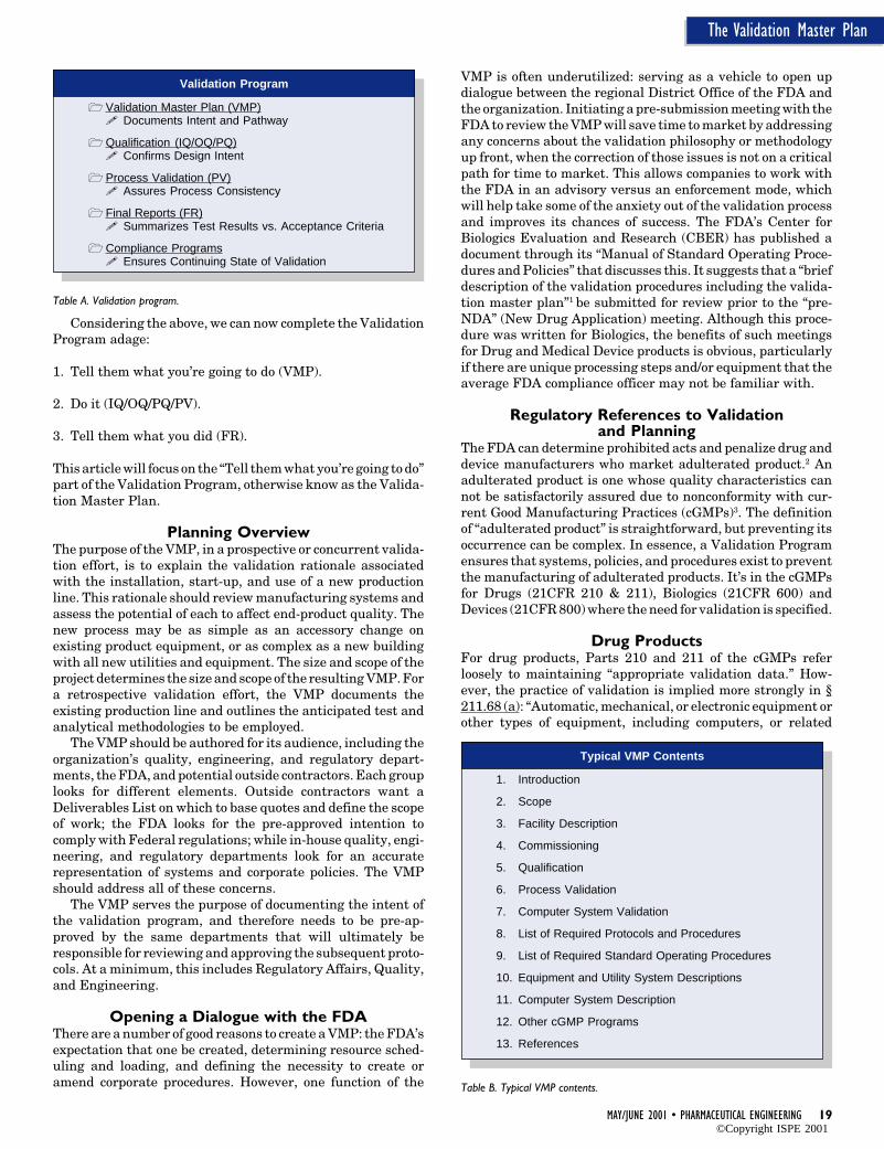
an umbrella term, encompassing all of the com-ponents below - Table A.
Validation Master Plan (VMP)The VMP serves as the validation roadmap,setting the course, justifying the strategy, out-lining the preliminary test and acceptance cri-teria, and documenting the necessary programsthat ensure a continuing state of validation.
QualificationThe Qualification phase provides documenta-tion that equipment and utility systems wereinstalled properly through an Installation Quali-fication (IQ), operate correctly through an Op-erational Qualification (OQ), and perform effec-tively through a Performance Qualification (PQ).Qualification assures that the criteria set forthin the Basis of Design documents generated atproject inception have been met in the fieldinstallation.
Process ValidationBuilding on the data generated from the Quali-fication phase, the Process Validation (PV) phasefocuses on the reproducibility of the systemsused and the resulting product quality. Thisprogram challenges the ability of the systemsused (methods, equipment, and operators) tomeet the pre-approved design intent.
Final ReportsFinal Reports (FR) compare the conclusions ofdata gathered to the acceptance criteria out-lined in the Qualification and Validation phases.They determine the pass/fail status and ad-dress the resolution of any deviations. They alsocan be referred to as Summary Reports.
Compliance ProgramsThe Validation program must ensure policiesand procedures comply with current Good Manu-facturing Practices (cGMP). Systems such ascalibration, preventative maintenance, changecontrol, and revalidation contribute to a con-tinuous state of validation.
Reprinted from The Official Journal of ISPE
PHARMACEUTICAL ENGINEERING® May/June, 2001 Vol. 21 No. 3
©Copyright ISPE 2001
MAY/JUNE 2001 • PHARMACEUTICAL ENGINEERING 19
The Validation Master Plan
Considering the above, we can now complete the ValidationProgram adage:
1. Tell them what you’re going to do (VMP).
2. Do it (IQ/OQ/PQ/PV).
3. Tell them what you did (FR).
This article will focus on the “Tell them what you’re going to do”part of the Validation Program, otherwise know as the Valida-tion Master Plan.
Planning OverviewThe purpose of the VMP, in a prospective or concurrent valida-tion effort, is to explain the validation rationale associatedwith the installation, start-up, and use of a new productionline. This rationale should review manufacturing systems andassess the potential of each to affect end-product quality. Thenew process may be as simple as an accessory change onexisting product equipment, or as complex as a new buildingwith all new utilities and equipment. The size and scope of theproject determines the size and scope of the resulting VMP. Fora retrospective validation effort, the VMP documents theexisting production line and outlines the anticipated test andanalytical methodologies to be employed.
The VMP should be authored for its audience, including theorganization’s quality, engineering, and regulatory depart-ments, the FDA, and potential outside contractors. Each grouplooks for different elements. Outside contractors want aDeliverables List on which to base quotes and define the scopeof work; the FDA looks for the pre-approved intention tocomply with Federal regulations; while in-house quality, engi-neering, and regulatory departments look for an accuraterepresentation of systems and corporate policies. The VMPshould address all of these concerns.
The VMP serves the purpose of documenting the intent ofthe validation program, and therefore needs to be pre-ap-proved by the same departments that will ultimately beresponsible for reviewing and approving the subsequent proto-cols. At a minimum, this includes Regulatory Affairs, Quality,and Engineering.
Opening a Dialogue with the FDAThere are a number of good reasons to create a VMP: the FDA’sexpectation that one be created, determining resource sched-uling and loading, and defining the necessity to create oramend corporate procedures. However, one function of the
VMP is often underutilized: serving as a vehicle to open updialogue between the regional District Office of the FDA andthe organization. Initiating a pre-submission meeting with theFDA to review the VMP will save time to market by addressingany concerns about the validation philosophy or methodologyup front, when the correction of those issues is not on a criticalpath for time to market. This allows companies to work withthe FDA in an advisory versus an enforcement mode, whichwill help take some of the anxiety out of the validation processand improves its chances of success. The FDA’s Center forBiologics Evaluation and Research (CBER) has published adocument through its “Manual of Standard Operating Proce-dures and Policies” that discusses this. It suggests that a “briefdescription of the validation procedures including the valida-tion master plan”1 be submitted for review prior to the “pre-NDA” (New Drug Application) meeting. Although this proce-dure was written for Biologics, the benefits of such meetingsfor Drug and Medical Device products is obvious, particularlyif there are unique processing steps and/or equipment that theaverage FDA compliance officer may not be familiar with.
Regulatory References to Validationand Planning
The FDA can determine prohibited acts and penalize drug anddevice manufacturers who market adulterated product.2 Anadulterated product is one whose quality characteristics cannot be satisfactorily assured due to nonconformity with cur-rent Good Manufacturing Practices (cGMPs)3. The definitionof “adulterated product” is straightforward, but preventing itsoccurrence can be complex. In essence, a Validation Programensures that systems, policies, and procedures exist to preventthe manufacturing of adulterated products. It’s in the cGMPsfor Drugs (21CFR 210 & 211), Biologics (21CFR 600) andDevices (21CFR 800) where the need for validation is specified.
Drug ProductsFor drug products, Parts 210 and 211 of the cGMPs referloosely to maintaining “appropriate validation data.” How-ever, the practice of validation is implied more strongly in §211.68 (a): “Automatic, mechanical, or electronic equipment orother types of equipment, including computers, or related
Table A. Validation program.
Validation Program
Validation Master Plan (VMP)Documents Intent and Pathway
Qualification (IQ/OQ/PQ)Confirms Design Intent
Process Validation (PV)Assures Process Consistency
Final Reports (FR)Summarizes Test Results vs. Acceptance Criteria
Compliance ProgramsEnsures Continuing State of Validation
Table B. Typical VMP contents.
Typical VMP Contents
1. Introduction
2. Scope
3. Facility Description
4. Commissioning
5. Qualification
6. Process Validation
7. Computer System Validation
8. List of Required Protocols and Procedures
9. List of Required Standard Operating Procedures
10. Equipment and Utility System Descriptions
11. Computer System Description
12. Other cGMP Programs
13. References
©Copyright ISPE 2001
20 PHARMACEUTICAL ENGINEERING • MAY/JUNE 2001
The Validation Master Plan
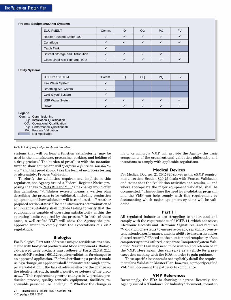
Table C. List of required protocols and procedures.
Process Equipment/Other Systems
EQUIPMENT Comm. IQ OQ PQ PV
Reactor System Series 100
Centrifuge
Catch Tank
Solvent Storage and Distribution
Glass Lined Mix Tank and TCU
Utility Systems
UTILITY SYSTEM Comm. IQ OQ PQ PV
Fire Water System
Breathing Air System
Cold Glycol System
USP Water System
HVAC
LegendComm.: Commissioning
IQ: Installation QualificationOQ: Operational QualificationPQ: Performance QualificationPV: Process Validation
Not Applicable
systems that will perform a function satisfactorily, may beused in the manufacture, processing, packing, and holding ofa drug product.” The burden of proof lies with the manufac-turer to show equipment will “perform a function satisfacto-rily,” and that proof should take the form of in-process testingor alternately, Process Validation.
To clarify the validation requirements implicit in thisregulation, the Agency issued a Federal Register Notice pro-posing changes to Parts 210 and 211.4 One change would offerthis definition: “Validation protocol means a written plandescribing the process to be validated, including productionequipment, and how validation will be conducted….”5 Anotherproposed section states: “The manufacturer’s determination ofequipment suitability shall include testing to verify that theequipment is capable of operating satisfactorily within theoperating limits required by the process.”6 In both of thesecases, a well-crafted VMP will show the Agency the pre-approved intent to comply with the expectations of cGMPregulations.
BiologicsFor Biologics, Part 600 addresses unique considerations asso-ciated with biological products and blood components. Biologi-cal-derived drug products must adhere to Parts 210 & 211.Also, cGMP section § 601.12 requires validation for changes toan approved application. “Before distributing a product madeusing a change, an applicant shall demonstrate through appro-priate validation… the lack of adverse effect of the change onthe identity, strength, quality, purity, or potency of the prod-uct….”7 This requirement governs changes in “…product, pro-duction process, quality controls, equipment, facilities, re-sponsible personnel, or labeling….”8 Whether the change is
major or minor, a VMP will provide the Agency the basiccomponents of the organizational validation philosophy andintentions to comply with applicable regulations.
Medical DevicesFor Medical Devices, 21 CFR 820 serves as the cGMP require-ments section. Section 820.75 deals with Process Validationand states that the “validation activities and results, … andwhere appropriate the major equipment validated, shall bedocumented.”9 This outlines the need for a validation program,and the VMP can help comply with this requirement bydocumenting which major equipment systems will be vali-dated.
Part 11All regulated industries are struggling to understand andcomply with the requirements of 21CFR 11, which addressesElectronic Records and Electronic Signatures, and requires“Validation of systems to ensure accuracy, reliability, consis-tent intended performance, and the ability to discern invalid oraltered records.”10 Based on the number and complexity of thecomputer systems utilized, a separate Computer System Vali-dation Master Plan may need to be written and referenced inthe VMP. Here again, this can serve as a vehicle for a pre-execution meeting with the FDA in order to gain guidance.
These specific instances do not explicitly detail the require-ment for a Validation Master Plan; however, a properly craftedVMP will document the pathway to compliance.
VMP ReferencesIncreasingly, the FDA is showing it agrees. Recently, theAgency issued a “Guidance for Industry” document, meant to
©Copyright ISPE 2001
MAY/JUNE 2001 • PHARMACEUTICAL ENGINEERING 21
The Validation Master Plan
reflect the Agency’s current thinking, that explicitly calls outfor a VMP. In “Guidance on Quality System Regulation Infor-mation for Various Pre-Market Submissions,” a requirementof the Quality System Manufacturing Dossier is “a copy of theValidation Master Plan or a description of which manufactur-ing processes have been or will be validated. A ValidationMaster Pan is a convenient method of quality planning forprocess validations required in the manufacturing of thedevice (§ 820.20(d)).”11 Clearly the expectation of theAgency is that organizations have a validation strategy as partof product and process development, and translate that strat-egy into a plan that will lead to an installation compliant withregulatory requirements.
The Validation Master PlanListed below are the headings for the major sections of a VMPfollowed by a description of the purpose and the suggestedcontent - Table B.
1. IntroductionThis section should include the company name, location, divi-sion or subsidiary name (if applicable) and business sectorserved. A short overview of the project provides the reader withthe necessary background from a macro standpoint. A cross-reference to the relevant company Quality Assurance Policy isappropriate here.
2. ScopeThis section defines the breadth and reach of the validationeffort covered by the VMP. A brief description of the installa-tion, whether single- or multi-product, and a breakdown ofinstalled equipment as new or existing should be includedhere.
3. Facility DescriptionWhether the project is a new building, extension, or remodel-ing of a current building, the facility characteristics are listedhere. The number of floors, the inter-connectivity of processand utility systems, isolation means, and the design productand personnel flow used to minimize cross-contamination areidentified. Be sure to note any room classification (cleanroomcertification levels) and specialty surfaces and finishes inte-gral to achieving the required product quality. Process FlowDiagrams (PFDs) are useful here, depicting the anticipatedpersonnel, raw material, process, and waste material flow. Theemphasis here is on design considerations to eliminate cross-contamination of material.
4. CommissioningDocument here the selection criteria governing what equip-ment and utility systems will undergo Commissioning. AsCommissioning is not part of the Validation Program and isnot regulated by the FDA, people often wonder why theyshould include this section at all. The reason is the FDA is justas interested in the rationale behind why one system is not
““ ““…address the selection criteria governingwhat equipment and utility systems need to
undergo Process Validation.
validated while another is. The VMP needs to answer thatquestion, identifying support utilities that do not need to bevalidated because they do not directly affect product quality. Italso demonstrates thoroughness, showing the FDA that allsystems have been examined for product quality impact. Tomaximize the usefulness of commissioning, the system shouldbe tested within the anticipated operating range of the respec-tive OQ.
5. QualificationThe selection criteria governing what equipment and utilitysystems will undergo Qualification is discussed here. Indi-vidual definitions of IQ, OQ, and PQ, may be included. Com-pany policies, regulatory references, and published guidelinesused in this selection process should be addressed. This discus-sion may include considerations such as product contactingsurfaces, critical/non-critical instrumentation, direct and indi-rect systems,12 and downstream processing, among others. Adiscussion of protocol and final report formats may be includedhere, with either a reference to existing protocol developmentprocedures, or a description of the format to be utilized. FinalReports may be generated as attachments to the protocolsthemselves, or as separate documents.
6. Process ValidationThis section addresses the selection criteria governing whatequipment and utility systems need to undergo Process Vali-dation. Company policies, regulatory references, and pub-lished guidelines utilized in the selection process should beaddressed. One such criteria is if the “results of a processcannot be fully verified by subsequent inspection and test, theprocess shall be validated….”13 Also included is a discussion onthe appropriate Cleaning Validations (CV) required to verifyinter- and intra-campaign cleaning methods. If this is to be afinished product, Packaging and Sterility validation needs tobe addressed.
7. Computer System ValidationA separate section should be devoted to the discussion ofComputer Validation, whether that is in the form of a Pro-grammable Logic Controller (PLC) or a Distributed ControlSystem (DCS). Computer Validation criteria also should bediscussed, and whether the installed control system is to be 21CFR 11 compliant, i.e., secure audit trails, authority checks,etc.
8. List of Required Protocols and ProceduresInclude here a tabular representation of the equipment andutility systems, and the required protocols and proceduresassociated with each - Table C. This is the essence of the VMPbecause it defines the validation requirements for the project,and can be used to determine resource loading. This table cansubsequently be used as a “Deliverables List” if the validationeffort is contracted outside of the organization.
9. List of Required Standard Operating Procedures (SOPs)This should take the form of a tabular representation of theinstalled equipment and utility systems and the required SOPassociated with each, similar to the List of Required Protocolsand Procedures. This will help identify the level of SOPgeneration necessary to complete validation activities. Thesewill generally take the form of Operation, Maintenance, andCleaning SOPs.
©Copyright ISPE 2001
22 PHARMACEUTICAL ENGINEERING • MAY/JUNE 2001
The Validation Master Plan
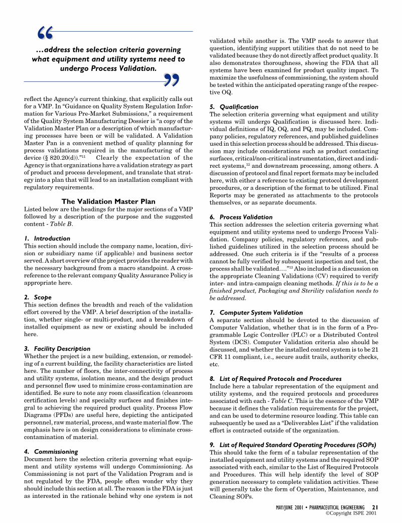
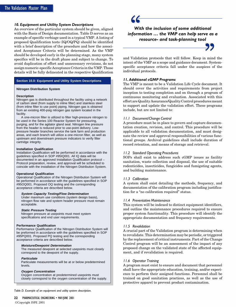
Table D. Example of an equipment and utility system description.
Section 10.0: Equipment and Utility System Descriptions
Nitrogen Distribution System
DescriptionNitrogen gas is distributed throughout the facility using a networkof carbon steel (from supply to inline filter) and stainless steel(from inline filter to use point) piping. Nitrogen gas is obtainedfrom an existing 400-psig nitrogen gas system located in thefacility.
A one-micron filter is utilized to filter high-pressure nitrogen tobe used in the Series 100 Reactor System for pressuring,purging, and for the agitator gland seal. Nitrogen line pressurefrom the header is reduced prior to use-point delivery. Low-pressure header branches service the tank farm and productionareas, and each branch will utilize a one-micron filter, as well asupstream and downstream pressure indicators to verify filtercartridge integrity.
Installation QualificationInstallation Qualification will be performed in accordance with theguidelines specified in SOP #95IQ001. All IQ data will bedocumented in an approved Installation Qualification protocol –Protocol preparation, review, and approval will be scheduled tocoincide with the installation of the Nitrogen Distribution System.
Operational QualificationOperational Qualification of the Nitrogen Distribution System willbe performed in accordance with the guidelines specified in SOP#95OQ001. Proposed OQ testing and the correspondingacceptance criteria are described below.
System Capacity Testing/Flow DeterminationUnder maximum use conditions (system design basis),nitrogen flow rate and system header pressure must remainacceptable.
Static Pressure TestingNitrogen pressure at usepoints must meet systemspecifications and end user requirements.
Performance QualificationPerformance Qualification of the Nitrogen Distribution System willbe preformed in accordance with the guidelines specified in SOP#95PQ001. Proposed PQ testing and the correspondingacceptance criteria are described below.
Moisture/Dewpoint DeterminationThe measured dewpoint at selected usepoints must closelycorrespond to the dewpoint of the supply.
ParticulateParticulate measurements will be at or below predeterminedlevels.
Oxygen ConcentrationOxygen concentration at predetermined usepoints mustclosely correspond to the oxygen concentration of the supply.
10. Equipment and Utility System DescriptionsAn overview of the particular system should be given, alignedwith the Basis of Design documentation. Table D serves as anexample of specific verbiage used in a typical VMP. A listing ofproposed Qualification tests (IQ/OQ/PQ) should be identifiedwith a brief description of the procedure and how the associ-ated Acceptance Criteria will be determined. As the VMPshould be developed early in the planning stage, many systemspecifics will be in the draft phase and subject to change. Toavoid duplication of effort and unnecessary revisions, do notassign numeric-specific Acceptance Criteria in the VMP. Thosedetails will be fully delineated in the respective Qualification
With the inclusion of some additionalinformation … the VMP can help serve as a
resource- and task-planning tool““ ““
and Validation protocols that will follow. Keep in mind theintent of the VMP as a scope and guidance document. System-specific acceptance criteria fall under the auspices of theindividual protocols.
11. Additional cGMP ProgramsThe VMP is meant to be a Validation Life Cycle document. Itshould cover the activities and requirements from projectinception to testing completion and on through a program ofcontinuous monitoring and evaluation. Associated with thiseffort are Quality Assurance/Quality Control procedures meantto support and update the validation effort. These programsinclude, but are not limited to:
11.1 Document/Change ControlA procedure must be in place to govern and capture documen-tation creation, revision, and control. This procedure will beapplicable to all validation documentation, and must desig-nate the review and approval responsibilities of various func-tional groups. Archival guidelines shall include duration ofrecord retention, and means of storage and retrieval.
11.2 Standard Operating ProceduresSOPs shall exist to address such cGMP issues as facilitysanitation, waste collection and disposal, the use of suitablerodenticides, insecticides, fungicides and fumigating agents,and building maintenance.
11.3 CalibrationA system shall exist detailing the methods, frequency, anddocumentation of the calibration program including justifica-tion for a “no calibration required” status.
11.4 Preventative MaintenanceThis system will be indexed to distinct equipment identifiers,and outline the maintenance procedures required to ensureproper system functionality. This procedure will identify theappropriate documentation and frequency requirements.
11.5 RevalidationA crucial part of the Validation program is determining whento revalidate. This determination may be periodic, or triggeredby the replacement of critical instruments. Part of the ChangeControl program will be an assessment of the impact of anyproposed change on the validated state of the affected equip-ment, and if revalidation is required.
11.6 Operator TrainingA program must exist to ensure and document that personnelshall have the appropriate education, training, and/or experi-ence to perform their assigned functions. Personnel shall betrained on good sanitation practices, as well as the use ofprotective apparel to prevent product contamination.
©Copyright ISPE 2001
MAY/JUNE 2001 • PHARMACEUTICAL ENGINEERING 23
The Validation Master Plan
12. ReferencesAll company policies and procedures, as well as any applicablelocal, state and federal regulations, and industry standardsreferenced should be listed.
Input to the VMPA certain minimum level of documentation needs to be devel-oped in order to produce a VMP. An equipment list, whichprovides basic specifications such as size/capacity, instrumen-tation and controls, design/operating limits, and capabilitiesneeds to be available. Additional documentation such as a“Design Basis” is important to delineate how equipment andutility systems should perform, independently and in concert,to produce the product. For Biologics and Pharmaceuticals,generally a set of preliminary Piping and InstrumentationDiagrams (P&IDs) helps define system boundaries. For Medi-cal Devices, the Manufacturing Flow Diagrams required in theManufacturing Dossier section of the Pre-Market Submissionalso may provide system boundary information.
Approval of the VMP prior to the generation of the associ-ated protocols is as important as approval of protocols prior todata collection. Just as protocols require QA approval prior toexecution, the VMP requires QA approval prior to protocolgeneration. The VMP should be under revision control, as itdocuments corporate approval of the scope and intent of thevalidation program, and will require QA approval. Any Basisof Design or validation philosophy changes should be pre-approved in the VMP prior to the generation of the affectedprotocols. The VMP needs to be updated to document majorproject scope changes such as the addition or deletion ofequipment, and project completion (i.e., release to production).This provides a clean audit trail of pre-approved intent versusexecution.
ConclusionIn its simplest form, the VMP is meant to document the majorequipment and utility systems associated with the productionprocess, assess the impact on the quality of the resultingproduct, and determine the validation requirements. With theinclusion of some additional information; however, the VMPcan help serve as a resource- and task-planning tool. Forinstance, a Deliverables List can be developed from the “List ofProtocols,” which can be used to gauge the man-hour require-ments of the job, for either internal budgeting or comparingoutside contractor quotes. The “Additional cGMP Programs”section can isolate the need for policies or procedures to becreated and/or updated.
The creation of a VMP at the beginning of the project servesmany purposes: to identify the timing and level of anticipatedresource needs, to document the corporation’s validation phi-losophy and individual elements, and to show the FDA the pre-approved intent to bring on a new product line in full compli-ance. It is well worth the extra time spent to write thisdocument at project inception, and to get early regulatoryfeedback via a pre-submission meeting with the FDA, than toanswer Agency questions during the approval cycle and paywith a delayed product launch date.
References1. U.S. Food and Drug Administration, Manual of Standard
Operating Procedures and Policies, Communication, SOPP8101.1, Version 1, Effectivity date February 11, 1999.
2. Federal Food, Drug and Cosmetic Act, Chapter III, Sec-tions 301, 303, 304, as amended by the FDA ModernizationAct of 1997.
3. Federal Food, Drug and Cosmetic Act, Chapter V, Section501 (a)(2)(B), as amended by the FDA Modernization Act of1997.
4. U.S. Food and Drug Administration, 21 CFR parts 210 &211, Proposed Rule, Federal Register, Friday May 3 1996Docket No. 95N-0362.
5. U.S. Food and Drug Administration, 21 CFR parts 210 &211, Proposed Rule, Federal Register, Friday May 3, 1996Docket No. 95N-0362, page 20113, proposed § 210.3 (b)(23).
6. U.S. Food and Drug Administration, 21 CFR parts 210 &211, Proposed Rule, Federal Register, Friday May 3, 1996Docket No. 95N-0362, page 20115, proposed § 211.220 (c).
7. U.S. Food and Drug Administration, 21 CFR 601.12 (a),April 1, 2000.
8. IBID
9. U.S. Food and Drug Administration, 21 CFR 820.75 (a),April 1, 2000.
10. U.S. Food and Drug Administration, 21 CFR 11.10 (a),April 1, 2000.
11. U.S. Food and Drug Administration, “Guidance for Indus-try and/or for FDA Staff: Guidance on Quality SystemRegulation Information for Various PreMarket Submis-sions,” Draft Guidance-Not for Implementation, Draft re-leased for comment on August 3, 1999, Section 19. DesignHistory File (DHF).
12. ISPE Baseline® Pharmaceutical Engineering Guide: Phar-maceutical Engineering Guides for New and RenovatedFacilities; Volume 3, Sterile Manufacturing Facilities,First Edition, January 1999, pages 119-120.
13. U.S. Food and Drug Administration, 21 CFR 820.75 (a),April 1, 2000.
About the AuthorBrian W. Saxton is the Manager of Validation Services atProcess Facilities Inc. in Boston, MA. He is responsible forclient-based validation programs including master planning,protocol generation and execution, and final reporting. He hasbeen involved in developing and executing validation pro-grams for the past 12 years for various regulated industries.He has a BS in chemical engineering from Manhattan College,Bronx, New York, and an MBA from Boston University, Bos-ton, MA.
Process Facilities Inc., 160 Federal St., Boston MA [email protected].
©Copyright ISPE 2001
84 PHARMACEUTICAL ENGINEERING • MAY/JUNE 2001
Product Protection
Product Protection in thePharmaceutical Industry –Meeting the Challenge
Product Protection in thePharmaceutical Industry –Meeting the Challenge
Aby Hitesh Patel
This articlehighlights thelatestdevelopments inmetal detectionfor thepharmaceuticalindustry andaddresses someof thecontaminationissues thatpharmaceuticalproducers needto be aware of.
Introduction
A lthough the installation of metal detec-tion systems is not specifically requiredby legislation, most manufacturers
have adopted stringent standards and protocolswhich demand “best practice,” usually fullyrecognizing the requirements and guidelines ofthe FDA1or USDA2. Increasingly, they are be-coming aware that product protection reachesfar beyond the law or regulations. Quality andintegrity are fundamental requirements for thepharmaceutical, healthcare, and nutritionalindustries. Whether for ethical pharmaceuticalformulations, generic equivalents, or over-the-counter solid dosage products, screening outcontamination guarantees the safety and qual-ity of goods, providing the manufacturer withpeace of mind against potential liability claimsfrom retailers and consumers; not to mentionthe loss of customer credibility that could resultfrom a failure in the contaminant detectionprocedures. Most importantly, the manufac-turer is able to deliver what the customer needsand wants - a safe, contaminant-free product.
Of all the possible types of product contami-nation, metal particles still rank among the
most serious. Even with the most stringentcontrols possible on production techniques,metal contamination can and does occur. Everycrushing, sieving, mixing, or pressing processintroduces the danger that metallic particleswill find their way into the product. This iswhere metal detectors can - if properly used andinstalled - minimize the risk. With enhancedsensitivity and process capability, machinescan be customized to address the most difficultapplications. Sophisticated software packageshave been developed to assist the user, heightenthe performance of machines, and ensure theycan automatically facilitate controls within themanufacturer’s quality systems.
Protecting the Consumer –and Your Reputation
Foreign body contamination can include un-wanted materials, such as paper or plastics, butmetal continues to be the most common high-risk contaminant in pharmaceutical products.Metal contamination can occur as a result of:
• contaminants entering the production linealong with raw materials, ingredients, orformulations
• breakage of machinery or components suchas sieves, tablet press tooling, or materials-handling systems
• inadequate cleaning of machinery after main-tenance
Incorporating metal detection into the qualitycontrol processes significantly reduces thechance of costly product recalls, negative mediacoverage, and reputation devaluation.
For obvious reasons, process machinery inthe pharmaceutical industry has to undergoregular and intensive cleaning if products are toretain the required levels of quality and integ-rity. For metal detectors to be fully effective, itis vital that they can withstand these aggres-sive conditions. When changing from one active
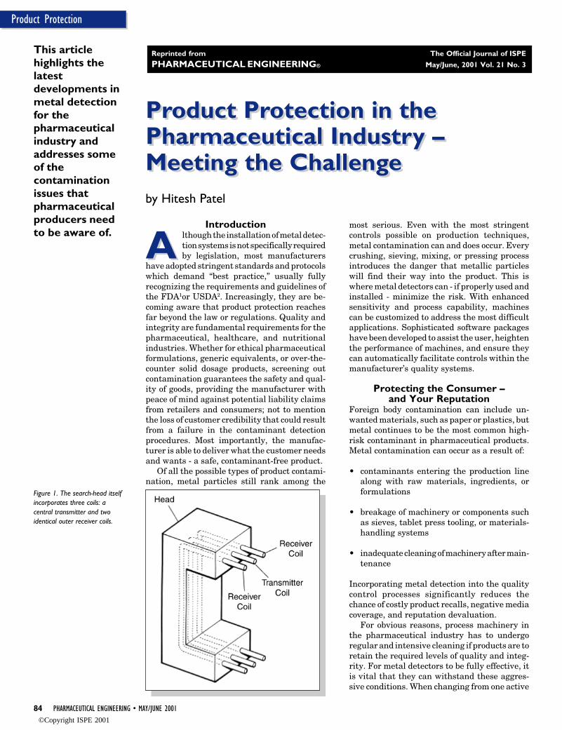
Figure 1. The search-head itselfincorporates three coils: acentral transmitter and twoidentical outer receiver coils.
Reprinted from The Official Journal of ISPE
PHARMACEUTICAL ENGINEERING® May/June, 2001 Vol. 21 No. 3
©Copyright ISPE 2001

MAY/JUNE 2001 • PHARMACEUTICAL ENGINEERING 85
Product Protection
ingredient to another, for example, machinery must be cleanedthoroughly. The detectors themselves should be constructedfrom materials such as 316 or 304 (Austenitic) stainless steel,which are impervious to corrosion and to the cleaning chemi-cals used. The design of the detector, too, can enhance itseffectiveness and resilience - for example, rounded surfaceedges can help prevent a build up of waste material or dust onthe body of the detector itself and flat, watertight key pads, orLCD/electroluminescent screens will allow for easy cleaning.
Metal Detectors ExplainedIndustrial metal detection systems generally comprise twoelements – the search-head (the sensor in the system) and theautomatic reject device. The search-head itself incorporatesthree coils (Figures 1 and 2): a central transmitter and twoidentical outer receiver coils. These are wound around the‘aperture,’ through which the product to be tested is passed. Anoscillator is connected to the center coil and produces a highfrequency alternating magnetic field. The two receiver coilsare connected so that their induced voltages are self-cancelingwhen the magnetic field is not being disturbed.
To achieve optimum sensitivity, the metal detector aper-ture should be of a size appropriate to the items or material inthe product flow: too large an aperture and there is a risk ofsignal ‘dilution’ and resultant loss in sensitivity; too small andthere may be insufficient allowance for product flow rates.When a contaminated product is introduced, the hidden metalelement interacts with the detector’s magnetic field and adisturbance is created.
Automatic Product CompensationConductive products, such as tablets containing iron, cancreate a signal when passing through the detector, even whencompletely free of metallic contamination. A detector withmicroprocessor operation is capable of memorizing the distur-bance signal that may result from the standard, non-contami-nated product. When a contaminated product is then intro-duced, the hidden metal element interacts differently with themagnetic field and the disturbance signal will alter as aconsequence. The difference may be very small, but processingtechnology has been developed to detect the minutest particles– commonly of a dimension of a fraction of a millimeter.
Figure 2. The two outer (receiver) coils are connected so that their induced voltagesare self-canceling when the magnetic field is not being disturbed.
Changes in temperature, mix, or moisture content of theproduct could traditionally cause similar variations in theproduct effect. With first generation, analog machines, thisgenerated false rejections and required broader tolerances,consequently reducing sensitivity. Modern digital machinesovercome these problems with automatic product tracking,ensuring that the highest levels of sensitivity and accuracy aremaintained.
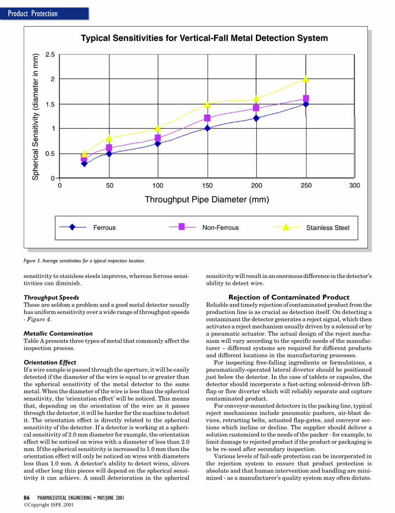
What Level of Performance is Possible?This is a question commonly asked of inspection equipment towhich there is no straightforward answer. Average sensitivi-ties for one common inspection location can be seen in Figure3.
Sensitivity is governed by two key factors: aperture size andoperating frequency. The smaller the size of the aperture, themore sensitive the head. For example, an aperture height of20mm will enable any metal contaminants as small as 0.2mmto be detected. Secondly, the higher the frequency, the greaterthe sensitivity. However, raising the frequency does not auto-matically guarantee detection as it may cause the productitself to generate a significant signal in the detector, (the‘product effect’). The aim, therefore, is to identify the optimumfrequency whereby the highest achievable sensitivity is bal-anced against product effect. In this way, the detector rejectscontaminants, avoids false readings, and product wastage. Thenewest digital metal detector technology does permit a veryhigh operating frequency of 1 megahertz; however, it stillprovides excellent stability, as they are fast becoming theindustry standard.
The Perfect Sphere?The sensitivity of a detector is usually described in terms of thediameter of a metal sphere because a sphere does not exhibitan ‘orientation effect’ (discussed below). It is not appropriate touse weight as a standard because it is possible for a metaldetector to detect a one-gram contaminant for example, but beunable to detect a two-gram contaminant due to its shape ororientation. In practice, contamination seldom appears in theform of a perfect sphere, but rather as metal slivers or wires.Detector ApertureThe size of the aperture of the detector is key with a largeraperture being less sensitive than a smaller one. Both aperturewidth and height have some effect on sensitivity althoughchanges in the minimum aperture dimensions will have agreater effect. The detector’s capability should be given interms of the minimum spherical particle size that can alwaysbe detected in the geometric center of the aperture. The typeand grade of metal also should be specified.
The sensitivity of the detector will depend on where in theaperture it is measured. The geometric center of the apertureis the least sensitive point as it is furthest from the coils. Theaperture corners have the highest sensitivity. Anywhere be-tween the center and the corners the sensitivity will increaseaccording to the detector’s sensitivity gradient - a perfectdetector would have no gradient and have equalized sensitivitythroughout the aperture.
Operating FrequencyThe operating frequency must be selected according to theapplication; from as low as 25KHz to as high as 1 MHz. Theselection is made to optimize the unit’s sensitivity for eachspecific application. As the operating frequency is increased,
©Copyright ISPE 2001
86 PHARMACEUTICAL ENGINEERING • MAY/JUNE 2001
Product Protection
Figure 3. Average sensitivities for a typical inspection location.
sensitivity to stainless steels improves, whereas ferrous sensi-tivities can diminish.
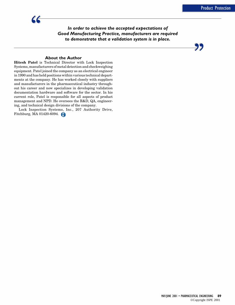
Throughput SpeedsThese are seldom a problem and a good metal detector usuallyhas uniform sensitivity over a wide range of throughput speeds- Figure 4.
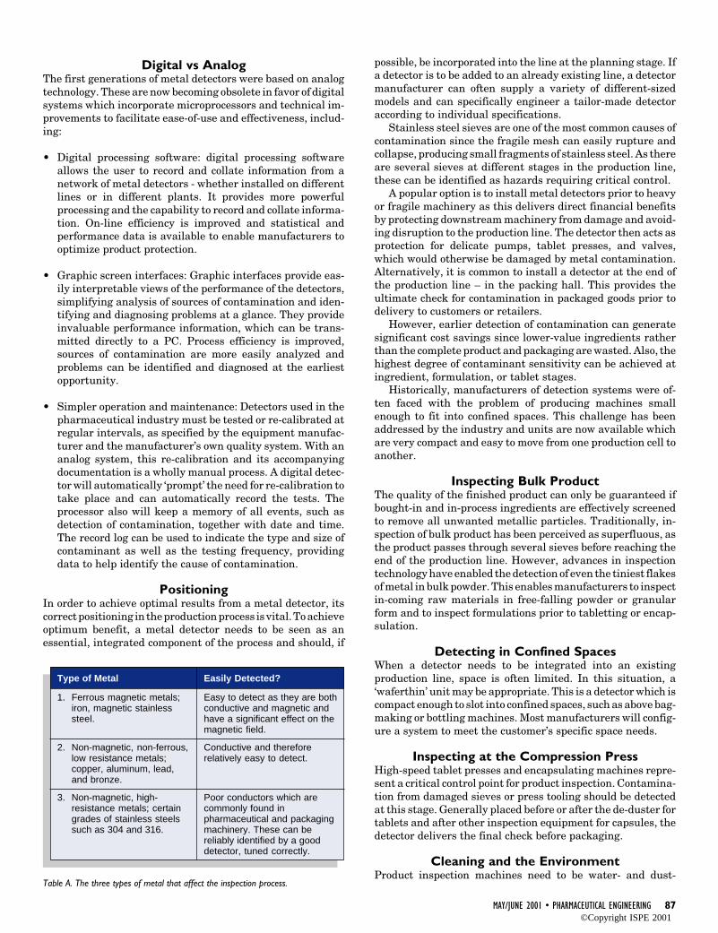
Metallic ContaminationTable A presents three types of metal that commonly affect theinspection process.
Orientation EffectIf a wire sample is passed through the aperture, it will be easilydetected if the diameter of the wire is equal to or greater thanthe spherical sensitivity of the metal detector to the samemetal. When the diameter of the wire is less than the sphericalsensitivity, the ‘orientation effect’ will be noticed. This meansthat, depending on the orientation of the wire as it passesthrough the detector, it will be harder for the machine to detectit. The orientation effect is directly related to the sphericalsensitivity of the detector. If a detector is working at a spheri-cal sensitivity of 2.0 mm diameter for example, the orientationeffect will be noticed on wires with a diameter of less than 2.0mm. If the spherical sensitivity is increased to 1.0 mm then theorientation effect will only be noticed on wires with diametersless than 1.0 mm. A detector’s ability to detect wires, sliversand other long thin pieces will depend on the spherical sensi-tivity it can achieve. A small deterioration in the spherical
sensitivity will result in an enormous difference in the detector’sability to detect wire.
Rejection of Contaminated ProductReliable and timely rejection of contaminated product from theproduction line is as crucial as detection itself. On detecting acontaminant the detector generates a reject signal, which thenactivates a reject mechanism usually driven by a solenoid or bya pneumatic actuator. The actual design of the reject mecha-nism will vary according to the specific needs of the manufac-turer – different systems are required for different productsand different locations in the manufacturing processes.
For inspecting free-falling ingredients or formulations, apneumatically-operated lateral diverter should be positionedjust below the detector. In the case of tablets or capsules, thedetector should incorporate a fast-acting solenoid-driven lift-flap or flow diverter which will reliably separate and capturecontaminated product.
For conveyor-mounted detectors in the packing line, typicalreject mechanisms include pneumatic pushers, air-blast de-vices, retracting belts, actuated flap-gates, and conveyor sec-tions which incline or decline. The supplier should deliver asolution customized to the needs of the packer - for example, tolimit damage to rejected product if the product or packaging isto be re-used after secondary inspection.
Various levels of fail-safe protection can be incorporated inthe rejection system to ensure that product protection isabsolute and that human intervention and handling are mini-mized - as a manufacturer’s quality system may often dictate.
©Copyright ISPE 2001
MAY/JUNE 2001 • PHARMACEUTICAL ENGINEERING 87
Product Protection
Digital vs AnalogThe first generations of metal detectors were based on analogtechnology. These are now becoming obsolete in favor of digitalsystems which incorporate microprocessors and technical im-provements to facilitate ease-of-use and effectiveness, includ-ing:
• Digital processing software: digital processing softwareallows the user to record and collate information from anetwork of metal detectors - whether installed on differentlines or in different plants. It provides more powerfulprocessing and the capability to record and collate informa-tion. On-line efficiency is improved and statistical andperformance data is available to enable manufacturers tooptimize product protection.
• Graphic screen interfaces: Graphic interfaces provide eas-ily interpretable views of the performance of the detectors,simplifying analysis of sources of contamination and iden-tifying and diagnosing problems at a glance. They provideinvaluable performance information, which can be trans-mitted directly to a PC. Process efficiency is improved,sources of contamination are more easily analyzed andproblems can be identified and diagnosed at the earliestopportunity.
• Simpler operation and maintenance: Detectors used in thepharmaceutical industry must be tested or re-calibrated atregular intervals, as specified by the equipment manufac-turer and the manufacturer’s own quality system. With ananalog system, this re-calibration and its accompanyingdocumentation is a wholly manual process. A digital detec-tor will automatically ‘prompt’ the need for re-calibration totake place and can automatically record the tests. Theprocessor also will keep a memory of all events, such asdetection of contamination, together with date and time.The record log can be used to indicate the type and size ofcontaminant as well as the testing frequency, providingdata to help identify the cause of contamination.
PositioningIn order to achieve optimal results from a metal detector, itscorrect positioning in the production process is vital. To achieveoptimum benefit, a metal detector needs to be seen as anessential, integrated component of the process and should, if
Type of Metal
1. Ferrous magnetic metals;iron, magnetic stainlesssteel.
2. Non-magnetic, non-ferrous,low resistance metals;copper, aluminum, lead,and bronze.
3. Non-magnetic, high-resistance metals; certaingrades of stainless steelssuch as 304 and 316.
Table A. The three types of metal that affect the inspection process.
Easily Detected?
Easy to detect as they are bothconductive and magnetic andhave a significant effect on themagnetic field.
Conductive and thereforerelatively easy to detect.
Poor conductors which arecommonly found inpharmaceutical and packagingmachinery. These can bereliably identified by a gooddetector, tuned correctly.
possible, be incorporated into the line at the planning stage. Ifa detector is to be added to an already existing line, a detectormanufacturer can often supply a variety of different-sizedmodels and can specifically engineer a tailor-made detectoraccording to individual specifications.
Stainless steel sieves are one of the most common causes ofcontamination since the fragile mesh can easily rupture andcollapse, producing small fragments of stainless steel. As thereare several sieves at different stages in the production line,these can be identified as hazards requiring critical control.
A popular option is to install metal detectors prior to heavyor fragile machinery as this delivers direct financial benefitsby protecting downstream machinery from damage and avoid-ing disruption to the production line. The detector then acts asprotection for delicate pumps, tablet presses, and valves,which would otherwise be damaged by metal contamination.Alternatively, it is common to install a detector at the end ofthe production line – in the packing hall. This provides theultimate check for contamination in packaged goods prior todelivery to customers or retailers.
However, earlier detection of contamination can generatesignificant cost savings since lower-value ingredients ratherthan the complete product and packaging are wasted. Also, thehighest degree of contaminant sensitivity can be achieved atingredient, formulation, or tablet stages.
Historically, manufacturers of detection systems were of-ten faced with the problem of producing machines smallenough to fit into confined spaces. This challenge has beenaddressed by the industry and units are now available whichare very compact and easy to move from one production cell toanother.
Inspecting Bulk ProductThe quality of the finished product can only be guaranteed ifbought-in and in-process ingredients are effectively screenedto remove all unwanted metallic particles. Traditionally, in-spection of bulk product has been perceived as superfluous, asthe product passes through several sieves before reaching theend of the production line. However, advances in inspectiontechnology have enabled the detection of even the tiniest flakesof metal in bulk powder. This enables manufacturers to inspectin-coming raw materials in free-falling powder or granularform and to inspect formulations prior to tabletting or encap-sulation.
Detecting in Confined SpacesWhen a detector needs to be integrated into an existingproduction line, space is often limited. In this situation, a‘waferthin’ unit may be appropriate. This is a detector which iscompact enough to slot into confined spaces, such as above bag-making or bottling machines. Most manufacturers will config-ure a system to meet the customer’s specific space needs.
Inspecting at the Compression PressHigh-speed tablet presses and encapsulating machines repre-sent a critical control point for product inspection. Contamina-tion from damaged sieves or press tooling should be detectedat this stage. Generally placed before or after the de-duster fortablets and after other inspection equipment for capsules, thedetector delivers the final check before packaging.
Cleaning and the EnvironmentProduct inspection machines need to be water- and dust-
©Copyright ISPE 2001
88 PHARMACEUTICAL ENGINEERING • MAY/JUNE 2001
Product Protection
Figure 4. A good metal detector usually has uniform sensitivity over a wide range ofthroughput speeds.
proofed to high industry standards - at least to NEMA 4X.3 Thisensures resilience to the arduous cleaning regimes that aresometimes essential. Additionally, construction materials needto be certified to withstand attack by the cleaning chemicalsused when changing from one live ingredient to another.
Finished Pack IntegrityInstalled in-process, a checkweigher can help ensure the propertablet count and compliance with label claims, as well aschecking for the presence of necessary leaflets or inserts. Anautomatic reject system can discard underweight packs andstill allow for acceptable product or packaging to be recoveredand reprocessed, reducing levels of waste. The importance ofmaintaining line speeds means that manufacturers shouldensure that a checkweigher is able to operate effectively at fullline speeds.
Combination Systems – Dual ActionAn integrated metal detector and checkweigher on the packag-ing line can additionally serve to protect against gross metalcontamination from slat counters, unscramblers, cottoners,etc. The systems are capable of segregating off-weight rejectedpacks from those contaminated with metal. This ensuresproper reconciliation of components for loss control recordsand satisfies regulatory requirements.
Inspecting BottlesThe inspection of tablet bottles sealed with a paper/metal foilor closed with a metal lid can present a particular challenge fora metal detector. It is advisable to inspect products prior tobottling or before the bottle enters the capping machine,thereby assuring the quality and purity of the final bottledproducts.
ValidationValidation procedures now represent an essential part ofpharmaceutical product safety and consistency managementand in order to achieve the accepted expectations of GoodManufacturing Practice, manufacturers are required to dem-onstrate that a validation system is in place. A lengthy process,the aim is to define everything that goes on in the manufactur-ing process, so that the actual equipment and materials usedin the plant can be proven against that standard, now or in thefuture. This means that an inspector or auditor can at any timecheck that the plant is operating as the technical peopledecreed it should operate, including every piece of machinery.A vital part of the damage-limitation exercise, validation isdesigned to eliminate amongst other risks, the danger ofcontamination to drugs.
Validation documentation consists of a series of proceduresand instructions for the end user. The FDA recommendscertain protocols to facilitate this: IQ (Installation Qualifica-tion), OQ (Operational Qualification), PQ (Performance Quali-fication), and SOP (Standard Operating Procedure). Together,
when completed, these comprise a complete set of validationdocuments.
Some equipment suppliers now supply framework valida-tion documents with their machines - a key provision that canhelp alleviate the validation burden, ease the processes ofinstallation, the subsequent operation, and the maintenanceof the machines. The scope of such validation embraces notonly the electrical and mechanical input of each machine’sconstruction, but also the methodology and standards used todevelop all embedded firmware and associated software.
ConclusionProduct protection is vital in today’s consumer-driven market.For pharmaceutical manufacturers, the correct installation ofa metal detector should constitute a fundamental part of thequality control management process. Advances in inspectiontechnology mean that the new generations of metal detectorsoffer improved benefits to manufacturers - such as enhancedmanagement data, automatic product tracking, superior rejec-tion systems, automatic prompting for re-calibration, greaterease of use and large product memories - in addition to superiorsensitivity, guaranteeing detection of even the most minuteparticle of metal. Although end-of-line remains a commonlocation for inspection, manufacturers are now recognizing thesignificant economic and process benefits to be gained fromincorporating metal detectors at earlier stages in the produc-tion process.
References1. 1986 FDA Final Rule: “Effective Measures Shall be Taken
to Protect Against the Inclusion of Metal or other Extrane-ous Material in Food.”
2. USDA/FSIS Directory 7310.4 (Rev.1).3. National Electrical Manufacturers Association (NEMA)
standard for the protection of electrical equipment. NEMA4X relates to enclosures for indoor and outdoor siting withprotection from corrosion, wind-driven dust and rain, andsplashed water.
““ ““Stainless steel sieves are one of the most commoncauses of contamination
since the fragile mesh can easily rupture and collapse.
©Copyright ISPE 2001
MAY/JUNE 2001 • PHARMACEUTICAL ENGINEERING 89
Product Protection
About the AuthorHitesh Patel is Technical Director with Lock InspectionSystems, manufacturers of metal detection and checkweighingequipment. Patel joined the company as an electrical engineerin 1990 and has held positions within various technical depart-ments at the company. He has worked closely with suppliersand manufacturers in the pharmaceutical industry through-out his career and now specializes in developing validationdocumentation hardware and software for the sector. In hiscurrent role, Patel is responsible for all aspects of productmanagement and NPD. He oversees the R&D, QA, engineer-ing, and technical design divisions of the company.
Lock Inspection Systems, Inc., 207 Authority Drive,Fitchburg, MA 01420-6094.
““ ““In order to achieve the accepted expectations ofGood Manufacturing Practice, manufacturers are required
to demonstrate that a validation system is in place.
©Copyright ISPE 2001
92 PHARMACEUTICAL ENGINEERING • MAY/JUNE 2001
The Cost of Quality
Increasing Value Through theMeasurement of the Cost ofQuality (COQ) – A PracticalApproach
Increasing Value Through theMeasurement of the Cost ofQuality (COQ) – A PracticalApproach
Eby Guy Malchi and Helen McGurk
This articlediscusses theimportance ofintroducing theconcept of theCOQ in thepharmaceuticalindustry, what ismeant by theCOQ, themethodology formeasuring theCOQ, thebenefits and asummary.
Introduction
E nsuring quality in the pharmaceuticalindustry is critical both to meet strin-gent cGMP regulations and to guaran-
tee safe products for customers. The trends inthe pharmaceutical industry, as with most in-dustries, are toward lower cost, higher quality,and greater added value to sustain competitiveadvantage and hence increase market share. Inan industry where quality has become a focalpoint of activity, it is still rare that the mostreliable measure, the Cost of Quality (COQ), iscaptured. The concept of the cost of quality is apowerful idea. Since profits and quality areintegrally linked, it is imperative that the costof quality is tracked, providing managers withthe ability to control costs and focus on improv-ing quality at reduced cost.
Quality is one of the most important aspectsof any pharmaceutical manufacturing company.The competitive pressures of today’s manufac-turing environment and the strict quality regu-lations placed on the pharmaceutical industrymean that quality products translate into higherprofit. Research has shown that companies per-ceived by customers to have superior qualityare up to three times more profitable than thoseperceived to have inferior quality. This undeni-able link between quality and profits combinedwith the need for cost reduction in a competingmarket mean that companies need to providehigh quality products at a lower cost. Measur-ing COQ is the first step in achieving thissuccess.
A product that does not meet the needs andrequirements of the customer cannot be definedas a quality product since it does not providecustomer satisfaction. Therefore, quality can bedefined as “Conformance to Requirements,” or amore traditional definition may be “Fitness forPurpose.” From this, the cost of quality can bedefined as: the cost of not conforming to cus-tomer requirements, and the cost of not provid-ing customer satisfaction. COQ can be defined
further as the cost of not doing activities “rightfirst time.”
Why Measure the COQ?It is unfortunate that the most accurate mea-sure of quality, the COQ, is still unclear in a lotof decision makers’ minds and often results in afigure much higher than imagined. Practicalexperience has shown that the COQ can be up to25% of gross sales, whereas it is often felt bymanagement to be around 5%. Capturing thereal COQ so that it can be managed and used asa benchmark measure is one reason alone tocalculate the COQ. This can then be used toreduce costs, and is done by increased quality or“right first time,” which results in reduced coststhrough increased efficiency and reduced non-conformance. Measuring the COQ is the firststep in this cost reduction program since itprovides the focus required.
What is the COQ?Traditional COQThe concept of the COQ did not emerge until the1950s with many different definitions beingassigned to this term.
Joseph M. Juran is one of the renownedfigures in quality management. He has writtenmany books on the subject and his theories andmethods are well known. He referred not to theCOQ, but rather to the cost of poor quality.
Traditionally the “cost of poor quality” wascategorized by Juran under four broad catego-ries. These four categories were:
Internal Failure CostsInternal failure costs are those associated withdefects and non-conformance that are foundbefore the product is shipped to the customer.They are defined as costs that would disappearif there were no defects in the product prior toshipment. Examples of these costs are the costof scrap, rework, reinspection, and reduced sell-ing price.
Reprinted from The Official Journal of ISPE
PHARMACEUTICAL ENGINEERING® May/June, 2001 Vol. 21 No. 3
©Copyright ISPE 2001

MAY/JUNE 2001 • PHARMACEUTICAL ENGINEERING 93
The Cost of Quality
External Failure CostsExternal Failure Costs are costs that are associated with aproduct that has been shipped to the customer. These costsalso would disappear if there were no defects in the product.Examples of these costs are complaint investigation, returnedmaterial, and allowances.
Appraisal CostsAppraisal costs are costs that are incurred in determining thedegree of conformance required to meet quality requirements.It is important to remember that what is classified as anappraisal cost is determined by the type of work done, not bythe department it comes under. Examples of this are allinspection and testing including raw material, in process, andfinished goods, audits, cost of keeping measuring equipmentcalibrated, whether conducted by the quality department,production, or an external laboratory.
Prevention CostsThese are the costs incurred in keeping failure and appraisalcosts to a minimum. These costs include quality planning, newproduct review, process control, supplier evaluation, qualitytraining, etc.
COQ System DefinitionThe approach taken is to design a hierarchy of indicators toeach company’s needs. These indicators are designed based onthe needs, goals, and analysis of the current state according tothe balanced scorecard philosophy. The COQ system is splitinto categories and elements.
The indicator hierarchy is normally made up of three tiers:1.Target, 2. Surrogate, and 3. Explanatory.
Target IndicatorsTarget Indicators represent the COQ categories; they are high-level management indicators. Examples are:
• Operating Cost
• Non Conformance Cost
Most of the Target Indicators are derived from the financesection of the balanced scorecard system.
Surrogate IndicatorsSurrogate Indicators are measures that have been identified tostrongly correlate to performance of the Target Indicators.They represent the COQ elements and are the focal points ofa COQ measurement system. Examples are:
• Cost of Preventative Labor/Output• Cost of Appraisal Labor/Output• Cost of Assets and Materials
Explanatory IndicatorsEach Surrogate Indicator can be supported by low-level mea-sures, called Explanatory Indicators that are used to supportthe investigation of high-level indicator performance. Ex-planatory Indicators promote understanding of the SurrogateIndicators at the local/operational level.
The hierarchical indicators system is designed to help makethe COQ more explanatory and practical to all managementlevels, by incorporating low-level indicators into the strategic
Target Indicators providing real awareness of where the costsare being consumed.
Comparison between Traditional and Defined COQTable A highlights the relationships between the traditionalcost of quality measures and the cost of quality as definedthrough the hierarchical structure.
It is clear that although the categories defined for calculat-ing the cost of quality indicators are not the same as thetraditional COQ measures, all of the costs are covered.
In addition to these categories, there is a category for hiddencosts, i.e., alternative costs. It is important not to ignore hiddenquality costs just because they are difficult to measure since inmany companies they often have a significant impact on thebottom line. Juran also refers to these hidden costs, claimingthat the obvious COQ are only the tip of the iceberg.
Some of these traditional hidden costs are:
• lost sales as a result of quality• extra inventory• delays• unidentified scrap
Therefore the total cost of quality can be summarized as:
Total COQ =Operating Cost + Non Conformance Cost + Alternative Cost
The total cost of quality can be minimized by studying therelationship between the COQ and the rate of non-conform-ance. Figure 1 shows that when the cost of non-conformance ishigh the operating cost is low, i.e., little is being spent onprevention and appraisal, and vice versa. The optimal level iswhere the total costs are minimized and this is recognized nowas closer to zero defects.
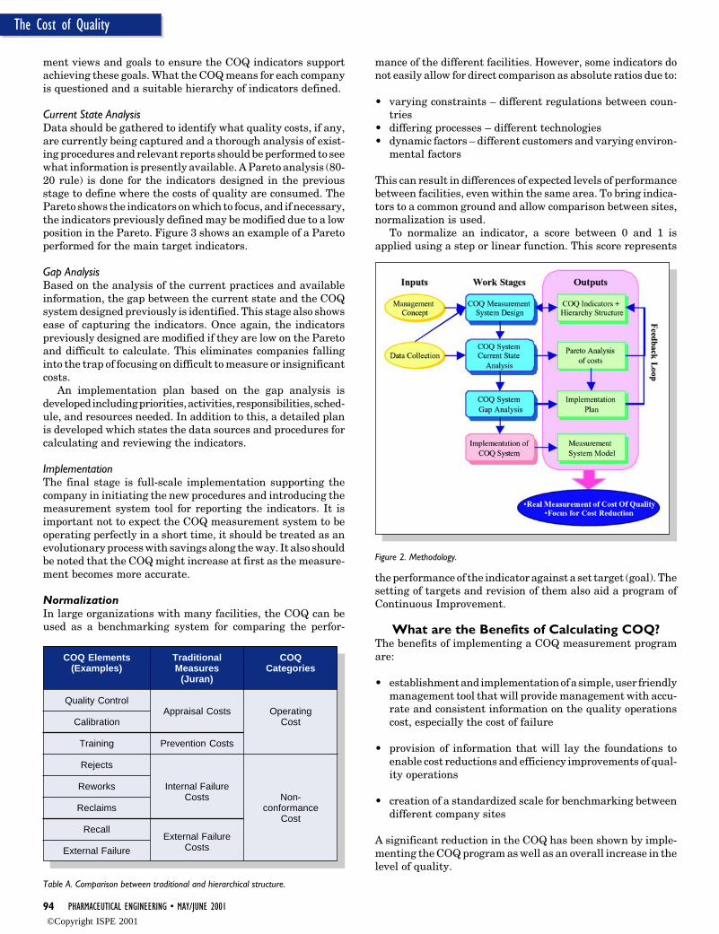
COQ Measurement System Design –Methodology
Measurement System DesignThe inputs and support of top management within a companyis critical for the success of any COQ measurement program.This is one of the reasons that the first stage involves inter-viewing company management to understand the manage-
Figure 1. Optimizing the COQ.
©Copyright ISPE 2001
94 PHARMACEUTICAL ENGINEERING • MAY/JUNE 2001
The Cost of Quality
ment views and goals to ensure the COQ indicators supportachieving these goals. What the COQ means for each companyis questioned and a suitable hierarchy of indicators defined.
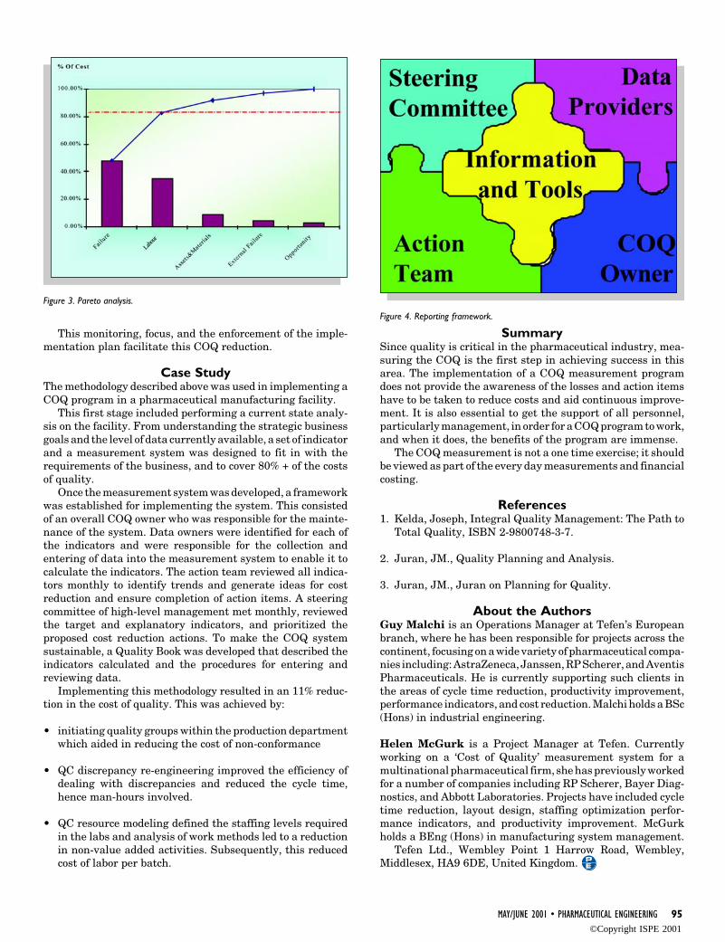
Current State AnalysisData should be gathered to identify what quality costs, if any,are currently being captured and a thorough analysis of exist-ing procedures and relevant reports should be performed to seewhat information is presently available. A Pareto analysis (80-20 rule) is done for the indicators designed in the previousstage to define where the costs of quality are consumed. ThePareto shows the indicators on which to focus, and if necessary,the indicators previously defined may be modified due to a lowposition in the Pareto. Figure 3 shows an example of a Paretoperformed for the main target indicators.
Gap AnalysisBased on the analysis of the current practices and availableinformation, the gap between the current state and the COQsystem designed previously is identified. This stage also showsease of capturing the indicators. Once again, the indicatorspreviously designed are modified if they are low on the Paretoand difficult to calculate. This eliminates companies fallinginto the trap of focusing on difficult to measure or insignificantcosts.
An implementation plan based on the gap analysis isdeveloped including priorities, activities, responsibilities, sched-ule, and resources needed. In addition to this, a detailed planis developed which states the data sources and procedures forcalculating and reviewing the indicators.
ImplementationThe final stage is full-scale implementation supporting thecompany in initiating the new procedures and introducing themeasurement system tool for reporting the indicators. It isimportant not to expect the COQ measurement system to beoperating perfectly in a short time, it should be treated as anevolutionary process with savings along the way. It also shouldbe noted that the COQ might increase at first as the measure-ment becomes more accurate.
NormalizationIn large organizations with many facilities, the COQ can beused as a benchmarking system for comparing the perfor-
mance of the different facilities. However, some indicators donot easily allow for direct comparison as absolute ratios due to:
• varying constraints – different regulations between coun-tries
• differing processes – different technologies• dynamic factors – different customers and varying environ-
mental factors
This can result in differences of expected levels of performancebetween facilities, even within the same area. To bring indica-tors to a common ground and allow comparison between sites,normalization is used.
To normalize an indicator, a score between 0 and 1 isapplied using a step or linear function. This score represents
Table A. Comparison between traditional and hierarchical structure.
COQ Elements(Examples)
Quality Control
Calibration
Training
Rejects
Reworks
Reclaims
Recall
External Failure
COQCategories
OperatingCost
Non-conformance
Cost
TraditionalMeasures
(Juran)
Appraisal Costs
Prevention Costs
Internal FailureCosts
External FailureCosts
Figure 2. Methodology.
the performance of the indicator against a set target (goal). Thesetting of targets and revision of them also aid a program ofContinuous Improvement.
What are the Benefits of Calculating COQ?The benefits of implementing a COQ measurement programare:
• establishment and implementation of a simple, user friendlymanagement tool that will provide management with accu-rate and consistent information on the quality operationscost, especially the cost of failure
• provision of information that will lay the foundations toenable cost reductions and efficiency improvements of qual-ity operations
• creation of a standardized scale for benchmarking betweendifferent company sites
A significant reduction in the COQ has been shown by imple-menting the COQ program as well as an overall increase in thelevel of quality.
©Copyright ISPE 2001
MAY/JUNE 2001 • PHARMACEUTICAL ENGINEERING 95
The Cost of Quality
This monitoring, focus, and the enforcement of the imple-mentation plan facilitate this COQ reduction.
Case StudyThe methodology described above was used in implementing aCOQ program in a pharmaceutical manufacturing facility.
This first stage included performing a current state analy-sis on the facility. From understanding the strategic businessgoals and the level of data currently available, a set of indicatorand a measurement system was designed to fit in with therequirements of the business, and to cover 80% + of the costsof quality.
Once the measurement system was developed, a frameworkwas established for implementing the system. This consistedof an overall COQ owner who was responsible for the mainte-nance of the system. Data owners were identified for each ofthe indicators and were responsible for the collection andentering of data into the measurement system to enable it tocalculate the indicators. The action team reviewed all indica-tors monthly to identify trends and generate ideas for costreduction and ensure completion of action items. A steeringcommittee of high-level management met monthly, reviewedthe target and explanatory indicators, and prioritized theproposed cost reduction actions. To make the COQ systemsustainable, a Quality Book was developed that described theindicators calculated and the procedures for entering andreviewing data.
Implementing this methodology resulted in an 11% reduc-tion in the cost of quality. This was achieved by:
• initiating quality groups within the production departmentwhich aided in reducing the cost of non-conformance
• QC discrepancy re-engineering improved the efficiency ofdealing with discrepancies and reduced the cycle time,hence man-hours involved.
• QC resource modeling defined the staffing levels requiredin the labs and analysis of work methods led to a reductionin non-value added activities. Subsequently, this reducedcost of labor per batch.
Figure 3. Pareto analysis.
Figure 4. Reporting framework.
SummarySince quality is critical in the pharmaceutical industry, mea-suring the COQ is the first step in achieving success in thisarea. The implementation of a COQ measurement programdoes not provide the awareness of the losses and action itemshave to be taken to reduce costs and aid continuous improve-ment. It is also essential to get the support of all personnel,particularly management, in order for a COQ program to work,and when it does, the benefits of the program are immense.
The COQ measurement is not a one time exercise; it shouldbe viewed as part of the every day measurements and financialcosting.
References1. Kelda, Joseph, Integral Quality Management: The Path to
Total Quality, ISBN 2-9800748-3-7.
2. Juran, JM., Quality Planning and Analysis.
3. Juran, JM., Juran on Planning for Quality.
About the AuthorsGuy Malchi is an Operations Manager at Tefen’s Europeanbranch, where he has been responsible for projects across thecontinent, focusing on a wide variety of pharmaceutical compa-nies including: AstraZeneca, Janssen, RP Scherer, and AventisPharmaceuticals. He is currently supporting such clients inthe areas of cycle time reduction, productivity improvement,performance indicators, and cost reduction. Malchi holds a BSc(Hons) in industrial engineering.
Helen McGurk is a Project Manager at Tefen. Currentlyworking on a ‘Cost of Quality’ measurement system for amultinational pharmaceutical firm, she has previously workedfor a number of companies including RP Scherer, Bayer Diag-nostics, and Abbott Laboratories. Projects have included cycletime reduction, layout design, staffing optimization perfor-mance indicators, and productivity improvement. McGurkholds a BEng (Hons) in manufacturing system management.
Tefen Ltd., Wembley Point 1 Harrow Road, Wembley,Middlesex, HA9 6DE, United Kingdom.
©Copyright ISPE 2001
46 PHARMACEUTICAL ENGINEERING • MAY/JUNE 2001
21 CFR Part 11
FDA Regulations of ComputerSystems in Drug Manufacturing –13 Years Later
FDA Regulations of ComputerSystems in Drug Manufacturing –13 Years Later
Sby Orlando López
This articlereviews theregulatoryrequirementsapplicable tocomputersystems in themanufacturingenvironmentbased on recentregulations.
Introduction
S ince 1963, the US Food and Drug Admin-istration (FDA) has considered valida-tion a current Good Manufacturing Prac-
tice (cGMP) requirement. The equipment, fa-cilities, processes, and procedures used in pro-duction and control shall be properly designedand tested to assure that the drug productshave proper identity, strength, quality, andpurity. This requirement also is applicable tocomputer systems performing functions cov-ered by the cGMP regulations or managingelectronic records known to be required by ex-isting regulation.1
In Volume 8, Number 5 of the Pharmaceuti-cal Engineering,2 was presented the FDA pointof view of the regulations applicable to processcontrol computers. Until 1988, the attention ofthe Agency to computer systems was not verysignificant. Since then, what has happened withthe cGMP regulations impacting computer sys-tems performing functions in the manufactur-ing environment?
The objective of this article is to go throughregulatory requirements applicable to computersystems in the manufacturing environmentbased on recent regulations. The discussion ofthe regulatory requirements before the approvalof Part 11 may provide the reader the founda-tion to understand 21 CFR Part 11; ElectronicRecords, Electronic Signatures Rule (hereafterreferred to as Part 11). In addition, this articleproposes the relevance of Part 11 as the newcomputer system validation model (Figure 1)and provides examples of how this model isapplicable to all computer systems.
US Regulatory Requirements forComputer Systems in cGMP
EnvironmentsRegulatory authorities hold the owner of thedata3 known to be required by existing regula-tion responsible for assuring the compliance ofthe computer systems recording and managingsuch data. The FDA established such responsi-bility in the Compliance Policy Guide (CPG)
7132a.12, “Vendor Responsibility.”The introduction by the FDA of such regula-
tory requirements can be traced back to the firstpublication of the regulations. In 1963, CFRPart 211.2(b) was incorporated as part of theregulations. It stressed on backups and docu-mentation, including having hardcopy of mas-ter formulas, specifications, test records, mas-ter production and control records, and batchproduction records (batch production and con-trol records), or calculations.
By 1976, the regulations combined Part211.2(b) and 211.68. The outcome of this combi-nation was the updated 21 CFR Part 211.68(automatic, mechanical, and electronic equip-ment). In summary, Part 211.68 requires that:
• There must be a written program detailingthe maintenance of the computer system.
• There must be a system to control changes tothe computer hardware and software, in-cluding documentation.
• There must be documented checks of Inputsand Outputs (I/Os) for accuracy. In actualpractice, it is implied that all computer sys-tems under the regulations must be quali-fied/validated.
• There must be programs to ensure accuracyand security of computer inputs, outputs,and data.
• Computer electronic records must be con-trolled, including backup, security, and re-tention.
Validation, as established in Part 211.68, is oneof the most important regulatory requirementsfor computer systems in the cGMP environ-ments.
The validation of computer systems estab-lishes conformance to the user, regulatory andsafety, and intended functions that have beenallocated to the computer. Computer systemsvalidation is an element of the system develop-ment life cycle. In addition to the software andhardware testing, other verification activitiesinclude code walkthroughs, dynamic analysis,
Reprinted from The Official Journal of ISPE
PHARMACEUTICAL ENGINEERING® May/June, 2001 Vol. 21 No. 3
©Copyright ISPE 2001
MAY/JUNE 2001 • PHARMACEUTICAL ENGINEERING 47
21 CFR Part 11
and trace analysis.The key elements to successfully implement the validation
of computer system projects in manufacturing processes are:
• selection of a development methodology that best suits thenature of the system under development
• selection of hardware based on capacity and functionality• identification and consideration of the operational limits to
establish production procedures• identification of operational functions associated with the
users, process, regulatory, company standards, and safetyrequirements
• identification and testing of “worst case” production condi-tions
• reproducibility of the testing results based on statistics• documentation of the validation process• availability of written procedures to maintain the valida-
tion state of the computer system
Any modification to a component of a system must be evalu-ated to determine the impact to the system. If required,qualification/validation is to be re-executed totally or par-tially.
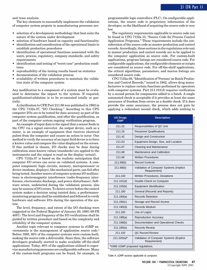
A clarification to CFR Part 211.68 was published in 1982 inthe CPG 7132a.07, “I/O Checking.” According to this CPGcomputer I/Os are to be tested for data accuracy as part of thecomputer system qualification, and after the qualification, aspart of the computer system ongoing verification program.
An example of input data is the signal that a sensor feeds tothe CPU via a signal converter. An output device, such as amotor, is an example of equipment that receives electricalpulses from the computer and causes an action to occur. Onemethod to verify the accuracy of an input field device is to forcea known value and compare the value displayed on the screen.If this method is chosen, I/O checks may be done duringcalibration since known values (standards) are applied to theinstruments and the output is read on the display (actual).
CPG 7132a.07 is based on the realistic anticipation thatcomputer I/O errors can occur on validated systems. A com-puter component (logic circuits, memory, microprocessor) ordevice (modems, displays), like mechanical parts, can fail afterbeing tested. Another source of computer systems I/O malfunc-tions is electromagnetic interference (radio-frequency inter-ference, electrostatic discharge, and power disturbance). Soft-ware errors, undetected during the validation process, alsomay be sources of I/O errors. To detect errors before the controlsystem makes a decision using tainted data, a performance-monitoring program shall be established and followed to verifyhardware and software I/Os during the operation of the sys-tem.
The level, frequency, and extent of the I/O checking weresuggested in the Federal Register of January 20, 1995 (60 FR4087). The level and frequency of the I/O verifications shall beguided by written procedure and based on the complexity andreliability of the computer system.
Another topic relevant to computer systems in cGMP en-vironments is the management of application source code.4
Before 1985, 80% of the computer systems were custom-built,making the source code a deliverable. Since then, the softwaredevelopers gradually started to make available off-the-shelfapplications. Today, 80% of the applications utilized to super-vise manufacturing processes are configurable software. Manyof the custom-built programs can be found, for example, in
programmable logic controllers (PLC). On configurable appli-cations, the source code is proprietary information of thedeveloper, so the likelihood of acquiring the source code is verylow.
The regulatory requirements applicable to source code canbe found in CPG 7132a.15, “Source Code for Process ControlApplication Programs.” These requirements include the con-sideration of the source code as master production and controlrecords. Accordingly, those sections in the regulations relevantto master production and control records are to be applied tothe computer application as source code. For custom-builtapplications, program listings are considered source code. Forconfigurable applications, the configurable elements or scriptsare considered as source code. For off-the-shelf applications,the critical algorithms, parameters, and macros listings areconsidered source code.
CPG 7132a.08, “Identification of ‘Persons’ on Batch Produc-tion and Control Records,” issued in 1982, allows drug manu-facturers to replace certain functions performed by operatorswith computer systems. Part 211.101(d) requires verificationby a second person for components added to a batch. A singleautomated check is acceptable if it provides at least the sameassurance of freedom from errors as a double check. If it doesprovide the same assurance, the process does not gain byapplying a redundant second check, which adds nothing to
Table A. cGMP sections applicable to computer.
US Drugs DescriptionGMP
211.22 Responsibilities of QC Unit
211.25 Personnel Qualifications
211.42 Design and Construction
211.63 Equipment Design, Size, and Location
211.67 Cleaning and Maintenance
211.68 Maintenance and Calibration
211.68 Written Procedures
211.68(b) Record Controls
211.68(b) Validation of Computer Systems (ImplicitRequirement)
211.100 Written Procedures, Deviations
211.101(d) Double Check on Computer
211.105(b) Equipment Identification
211.180 General (Records and Reports)
211.180(a) Records Retention
211.180(c) Storage and Record Access
211.180(d) Records Medium
211.182 Use of Log(s)
211.188(a) Reproduction Accuracy
211.188(b) Documentation and Operational Checks
211.189(e) Records Review
211.192 QC Record Review
211.220(a)* Validation of Computer Systems (ExplicitRequirement)
*1996 cGMP proposed regulations.
©Copyright ISPE 2001
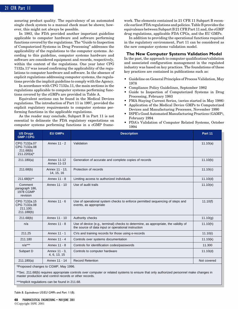
48 PHARMACEUTICAL ENGINEERING • MAY/JUNE 2001
21 CFR Part 11
assuring product quality. The equivalency of an automatedsingle check system to a manual check must be shown; how-ever, this might not always be possible.
In 1983, the FDA provided another important guidelineapplicable to computer hardware and software performingfunctions covered by the regulations. The “Guide to Inspectionof Computerized Systems in Drug Processing” addresses theapplicability of the regulations to the computer systems. Ac-cording to this guideline, computer systems hardware andsoftware are considered equipment and records, respectively,within the context of the regulations. One year later CPG7132a.115 was issued confirming the applicability of the regu-lations to computer hardware and software. In the absence ofexplicit regulations addressing computer systems, the regula-tions provide the implicit guideline to comply with the Agency.
In accordance with CPG 7132a.11, the main sections in theregulations applicable to computer systems performing func-tions covered by the cGMPs are provided in Table A.
Equivalent sections can be found in the Medical Devicesregulations. The introduction of Part 11 in 1997, provided theexplicit regulatory requirements to computer systems per-forming functions in the applicable regulations.
As the reader may conclude, Subpart B in Part 11 is notessential to delineate the FDA regulatory expectations oncomputer systems performing functions in a cGMP frame-
work. The elements contained in 21 CFR 11 Subpart B recon-cile earliest FDA regulations and policies. Table B provides theequivalence between Subpart B 21 CFR Part 11 and, the cGMPdrug regulations, applicable FDA CPGs, and the EU GMPs.
In addition to providing the operational functions requiredin the regulatory environment, Part 11 can be considered asthe new computer systems validation model.
The New Computer Systems Validation ModelIn the past, the approach to computer qualification/validationand associated configuration management in the regulatedindustry was based on key practices. The foundations of thesekey practices are contained in publications such as:
• Guideline on General Principles of Process Validation, May1978
• Compliance Policy Guidelines, September 1982• Guide to Inspection of Computerized Systems in Drug
Processing, February 1983• PMA Staying Current Series, (series started in May 1986)• Application of the Medical Device GMPs to Computerized
Devices and Manufacturing Processes, November 1990• ISPE’s Good Automated Manufacturing Practices (GAMP),
February 1994• PDA’s Validation of Computer Related Systems, October
1994
Table B. Equivalence US/EU GMPs and Part 11(B).
US Drugs EU GMPs Description Part 11GMP / CPG
CPG 7132a.07 Annex 11 - 2 Validation 11.10(a)CPG 7132a.08
211.68(b)211.220(a)*
211.180(a) Annex 11-12 Generation of accurate and complete copies of records 11.10(b)Annex 11-13
211.68(b) Annex 11 - 13, Protection of records 11.10(c)14, 15, 16
211.68(b)** Annex 11 - 8 Limiting access to authorized individuals 11.10(d)
Comment Annex 11 - 10 Use of audit trails 11.10(e)paragraph 186,
1978 CGMPrevision
CPG 7132a.15 Annex 11 - 6 Use of operational system checks to enforce permitted sequencing of steps and 11.10(f)CPG 7132a.08 events, as appropriate
211.100;211.188(b)
211.68(b) Annex 11 - 10 Authority checks 11.10(g)
n/a Annex 11 - 8 Use of device (e.g., terminal) checks to determine, as appropriate, the validity of 11.10(h)the source of data input or operational instruction
211.25 Annex 11 - 1 CVs and training records for those using e-records 11.10(i)
211.180 Annex 11 - 4 Controls over systems documentation 11.10(k)
n/a*** Annex 11 - 8 Controls for identification codes/passwords 11.300
Subpart D Annex 11 - 3, Controls to computer hardware 11.10(d)4, 6, 13, 15
211.180(a) Annex 11 - 14 Record Retention Not covered
*Proposed changes to CGMP, May 1996.
**Sec. 211.68(b) requires appropriate controls over computer or related systems to ensure that only authorized personnel make changes inmaster production and control records or other records.
***Implicit regulations can be found in 211.68.
©Copyright ISPE 2001
MAY/JUNE 2001 • PHARMACEUTICAL ENGINEERING 49
21 CFR Part 11
• General Principles of Software Validation, Draft Guidance,June 1997
• Best Practices for Computerized Systems in Regulated GxPEnvironments, PIC, Draft Rev 3.01
The constraint of key practices is that these “need to bemonitored and evaluated periodically to ensure that they aresuitable and to keep them current with industry and regula-tory trends.”6 Across the industry, not all key practices wereimplemented at the same time, making related key practicesdivergent.
Part 11 provides the explicit and current regulatory trendsapplicable to computer systems performing functions in theapplicable regulations. Now that the regulatory expectationsare clearly established, the implementation of Part 11 is nowcontingent to the availability of appropriate applications com-pliant with the regulation. In the absence of technologiessupporting Part 11, the required controls are procedural innature.
Figure 1 depicts the new validation model introduced in thisarticle. The elements to be verified and/or qualified during asoftware implementation are the type of system (open orclosed), security functions, audit trails, process controlled bythe computer system, and the implementation of the technol-ogy in support of the process and Part 11. These two lastelements are not identical for all systems. Electronic signa-tures are tested when this technology is implemented. Anelement out of the scope of this model is the retention ofelectronic records, but the model shall be used to verify andvalidate the implementation of the system(s) that will holdthese records.
For applications using electronic or digital signatures, thecurrent validation/qualification model requires verificationand/or testing to many of the following:
1. Open/Closed Systems
2. Securitya. System Securityb. Electronic Signature Securityc. Codes and Passwords Maintenance
• Codes and Passwords Security• Passwords Assignment
d. Document Controlse. Authority, Operational, and Location Checksf. Records Protection
3. Audit Trailsa. Audit Mechanismb. Metadatac. Display and Reporting
4. Electronic signaturesa. E-Sign without Biometric/Behavioralb. E-Sign with Biometric/Behavioralc. Signature Manifestationd. Signature Purposee. Signature Binding
5. Certification to FDA
A subset of the above is applicable to hybrid computer sys-tems.7 The implementation of these requirements was dis-
cussed in other articles.8,9
Figure 2 depicts the progression of the computer systemsvalidation practices from current key practices to 21 CFRPart 11 Model. The transition program consists of educatingthe regulated industry, assessing current computer systems,and implementing the regulations using the appropriate tech-nologies. This model is easily applicable to the new generationof computer systems by incorporating the requirements com-bined in Part 11 at the beginning the development process. Forthe current generation of systems, an assessment shall beperformed to evaluate the level of conformity with the regula-tion.
Sample SituationsThe objective of the following sample situations is to demon-strate the applicability of Part 11 as the new computer systemsvalidation model. Each sample situation is focused on manu-facturing equipment controlled by computer systems. Theprimary concern of these systems is that the software workscorrectly in the intended manufacturing process. The recordsrequired by Part 211 or Part 820, that are managed by thesesystems shall be reliable and authentic.
Programmable logic controllers are one of the favoritedevices to control manufacturing equipment. These are ca-pable of generating a vast amount of data stored in the PLCbattery-backed read access memory.11 At the moment the datais saved on magnetic media, these (electronic) records are usedfor future reference and/or archived.
In a typical automated manufacturing environment, batchproduction records are prepared using the data generatedmanually or by computer systems.
Documentation of completion to each significant step in thebatch production records should include:
• dates and, when appropriate, times• identity of major equipment (e.g., granulators, tumblers,
etc.) used• specific identification of each batch, including weights,
measures, and batch numbers of raw materials, intermedi-ates, or any reprocessed materials used during manufactur-ing
• actual results recorded for critical process parameters12
• any sampling performed• signatures of the persons performing and directly supervis-
ing or checking each critical step in the operation• any deviation noted, its evaluation, investigation conducted
(if appropriate) or reference to that investigation if storedseparately
• results of release testing.
First Example - Manufacturing Equipment with a Stand-Alone PLCFigure 3 depicts this example. A V-Shell Blender may be anexample of a typical oral solid dosage form manufacturingequipment that may have a stand-alone PLC or other type ofcontroller. The objective of this equipment is the reorientationof particles relative to one another in order to achieve unifor-mity.
The configuration on this first example consists of a manmachine interface implemented using a terminal with anoperator keyboard and printer. The keyboard may be used toenter variable set points,13 weights, batch number, menu num-ber, and other processing information. In this case, all I/Os are
©Copyright ISPE 2001
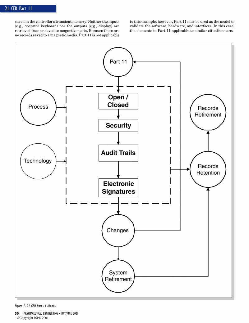
50 PHARMACEUTICAL ENGINEERING • MAY/JUNE 2001
21 CFR Part 11
saved in the controller’s transient memory. Neither the inputs(e.g., operator keyboard) nor the outputs (e.g., display) areretrieved from or saved to magnetic media. Because there areno records saved to a magnetic media, Part 11 is not applicable
to this example; however, Part 11 may be used as the model tovalidate the software, hardware, and interfaces. In this case,the elements in Part 11 applicable to similar situations are:
Figure 1. 21 CFR Part 11 Model.
©Copyright ISPE 2001
MAY/JUNE 2001 • PHARMACEUTICAL ENGINEERING 51
21 CFR Part 11
1. Operational Checks2. System Security3. Codes and Passwords Security4. Codes and Passwords Maintenance5. Password Assignment6. Location Checks7. Authority Checks8. Document Controls9. Open/Closed Systems10. Record Retention/Protection
Operational checks are application-dependent. Section 21CFR 211.188(b) specifies that each significant step in themanufacture, processing, packing, or holding of the batch shallbe documented. Section 21 CFR 211.188(b)(11) mandates theidentification of the persons performing and directly supervis-ing or checking each significant step in the operation.
The intent of the regulation is to secure that each step in themanufacturing, processing, packing, or holding of the batch isperformed and there are records to show this, from which thehistory of the lot could be traced. All critical sequence of eventsshall be verified. In PLC based systems, operational checks maybe incorporated in the software. The manufacturing procedures,control, instructions, specifications,14 and/or process safety mea-sures to be followed within such computer systems may be set aspart of the product manufacturing process under computercontrol. In a blender, for example, combining the amount ofblending time, blender speed, and the intensifier bar speed maybe performed in a specific sequence. The Research and Develop-ment (R&D) department establishes the criticality of any ofthese parameters and associated sequence. In summary, com-puter systems are to be checked to make sure that criticaloperations occurred in the proper sequence.
An acceptable means of complying with the operationalchecks may be as follows: (1) documentation of the program, (2)verification and testing that no step or specification can bemissed or poorly executed/assigned, and (3) documentation ofthe initial and final steps.15 The reader may realize that theapplication-dependent requirements become part of the com-puter systems validation model through the operational veri-fications.
In this first example, security is associated with prevent-ing accidental or intentional data manipulation, and corrup-tion of the data that is to be displayed on the screen or used tomake decisions to control the equipment. To avoid accidental,intentional, and/or lost data, the universe of data that will becollected, the procedures to collect it, and the means to verifyits integrity, accuracy, reliability, and consistency must bedefined. A Failure Modes and Effect Analysis (FMEA) is one ofmany methods to uncover and mitigate these factors. Forexample, to avoid data corruption, some measures shall betaken such as calibration of critical instruments16 and imple-mentation of an ongoing monitoring program.
Related to security is the logical access to computer sys-tems. It includes the capability of such systems to allow theuser access to the terminal and access to the parameters thatare loaded in the PLC. The user interface must have thecapability to have authority checks. The authority checksare based upon the various roles and responsibilities assignedto individuals known to the system. Computer systems shall bedesigned to make distinctions among control access (a) to thesystem, (b) to functions in the system, and (c) to input andoutput devices used by the system.
In this example, location check for the blender is not acritical element. The computer system is dedicated to thecontrol of the equipment. Location checks enable the applica-tion software to determine whether the input being generatedby a particular device is appropriate.
Passwords are one of many methods to authenticate autho-rized users. In view of the fact that security in cGMP systemsis very critical, the expectations on activities such as assign-ment, security, and maintenance of passwords are clearlyestablished by the FDA. Before Part 11, the FDA expected17
that passwords:
• be periodically changed, not be re-assigned and re-used• not be recognizable as reflections of their personal life• not be shared by the users
The FDA expects written procedures or company policies, andthe associated training on the subject of the use and securityof passwords.
To ensure computer systems security, password files maybe encrypted or otherwise secured so that passwords cannot beread by ordinary means. Password file encryption is verycommon in modern operating systems.
In general, the password assignment and maintenanceare a combination of written procedures and technologies tosupport this requirement. Sample procedures include pass-word aging, minimum password length, password uniqueness,default password management, and account lockout after areasonable number of unsuccessful login attempts.
The focus of the validation program is typically the qualityattributes of the system implementation, change control, andthe verification and testing of the modifications to the baseline.The complete configuration management, including the docu-mentation, is a key item of concern. Specifically, documenta-tion management is very critical to the information that iscontained in both the master production records and in theapplication.
System documentation means records that pertain to sys-tem operation and maintenance, from high-level design docu-ments to end user manuals. Controlling system documenta-tion includes assessing the documentation when a modifica-tion to the computer system is suggested. The high-leveldesign documentation provides the inputs for maintenanceand the user manuals provide the instructions of how tooperate the system.
According to Part 11, a computer system is consideredclosed if the person responsible for the content of electronicrecords allows the access to authorized parties. In addition, theelectronic records shall be monitored through the system’ssoftware with its required log-on, security procedures, andaudit trails. In PLC based systems, it is very common to havecommunications to telephone connection through modems. Aconnection such as this is used to perform diagnostics by thesystem developer/integrator. This practice should be disal-lowed. If allowed, then the access via modem should have strictaccess controls and restrictions including protective software.Access restrictions on such systems should be designed toprevent unauthorized modifications.
In this example, the batch production and control recordsare paper based. The operator records each significant step inthe manufacture of batches. The retention and protectionto the executed batches is based on the existing regulation. Theretention requirements to cGMP records can be found in
©Copyright ISPE 2001
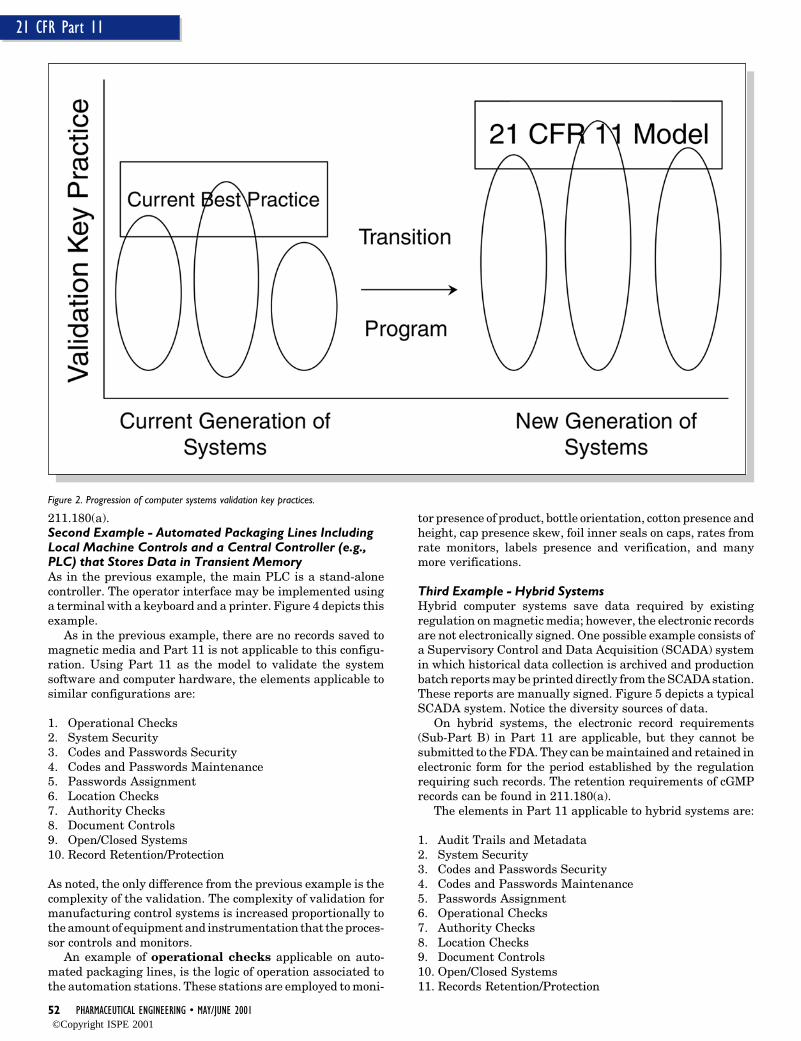
52 PHARMACEUTICAL ENGINEERING • MAY/JUNE 2001
21 CFR Part 11
Figure 2. Progression of computer systems validation key practices.
211.180(a).Second Example - Automated Packaging Lines IncludingLocal Machine Controls and a Central Controller (e.g.,PLC) that Stores Data in Transient MemoryAs in the previous example, the main PLC is a stand-alonecontroller. The operator interface may be implemented usinga terminal with a keyboard and a printer. Figure 4 depicts thisexample.
As in the previous example, there are no records saved tomagnetic media and Part 11 is not applicable to this configu-ration. Using Part 11 as the model to validate the systemsoftware and computer hardware, the elements applicable tosimilar configurations are:
1. Operational Checks2. System Security3. Codes and Passwords Security4. Codes and Passwords Maintenance5. Passwords Assignment6. Location Checks7. Authority Checks8. Document Controls9. Open/Closed Systems10. Record Retention/Protection
As noted, the only difference from the previous example is thecomplexity of the validation. The complexity of validation formanufacturing control systems is increased proportionally tothe amount of equipment and instrumentation that the proces-sor controls and monitors.
An example of operational checks applicable on auto-mated packaging lines, is the logic of operation associated tothe automation stations. These stations are employed to moni-
tor presence of product, bottle orientation, cotton presence andheight, cap presence skew, foil inner seals on caps, rates fromrate monitors, labels presence and verification, and manymore verifications.
Third Example - Hybrid SystemsHybrid computer systems save data required by existingregulation on magnetic media; however, the electronic recordsare not electronically signed. One possible example consists ofa Supervisory Control and Data Acquisition (SCADA) systemin which historical data collection is archived and productionbatch reports may be printed directly from the SCADA station.These reports are manually signed. Figure 5 depicts a typicalSCADA system. Notice the diversity sources of data.
On hybrid systems, the electronic record requirements(Sub-Part B) in Part 11 are applicable, but they cannot besubmitted to the FDA. They can be maintained and retained inelectronic form for the period established by the regulationrequiring such records. The retention requirements of cGMPrecords can be found in 211.180(a).
The elements in Part 11 applicable to hybrid systems are:
1. Audit Trails and Metadata2. System Security3. Codes and Passwords Security4. Codes and Passwords Maintenance5. Passwords Assignment6. Operational Checks7. Authority Checks8. Location Checks9. Document Controls10. Open/Closed Systems11. Records Retention/Protection
©Copyright ISPE 2001
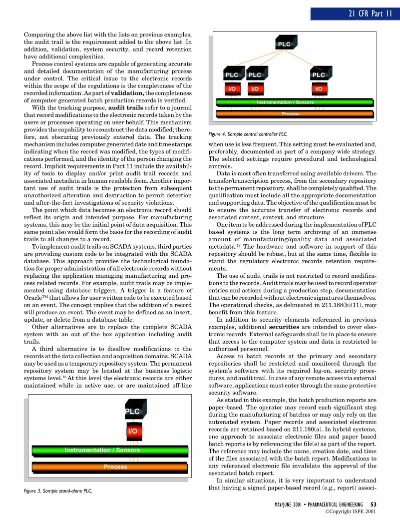
MAY/JUNE 2001 • PHARMACEUTICAL ENGINEERING 53
21 CFR Part 11
Comparing the above list with the lists on previous examples,the audit trail is the requirement added to the above list. Inaddition, validation, system security, and record retentionhave additional complexities.
Process control systems are capable of generating accurateand detailed documentation of the manufacturing processunder control. The critical issue to the electronic recordswithin the scope of the regulations is the completeness of therecorded information. As part of validation, the completenessof computer generated batch production records is verified.
With the tracking purpose, audit trails refer to a journalthat record modifications to the electronic records taken by theusers or processes operating on user behalf. This mechanismprovides the capability to reconstruct the data modified; there-fore, not obscuring previously entered data. The trackingmechanism includes computer generated date and time stampsindicating when the record was modified, the types of modifi-cations performed, and the identity of the person changing therecord. Implicit requirements in Part 11 include the availabil-ity of tools to display and/or print audit trail records andassociated metadata in human readable form. Another impor-tant use of audit trails is the protection from subsequentunauthorized alteration and destruction to permit detectionand after-the-fact investigations of security violations.
The point which data becomes an electronic record shouldreflect its origin and intended purpose. For manufacturingsystems, this may be the initial point of data acquisition. Thissame point also would form the basis for the recording of audittrails to all changes to a record.
To implement audit trails on SCADA systems, third partiesare providing custom code to be integrated with the SCADAdatabase. This approach provides the technological founda-tion for proper administration of all electronic records withoutreplacing the application managing manufacturing and pro-cess related records. For example, audit trails may be imple-mented using database triggers. A trigger is a feature ofOracle™ that allows for user written code to be executed basedon an event. The concept implies that the addition of a recordwill produce an event. The event may be defined as an insert,update, or delete from a database table.
Other alternatives are to replace the complete SCADAsystem with an out of the box application including audittrails.
A third alternative is to disallow modifications to therecords at the data collection and acquisition domains. SCADAmay be used as a temporary repository system. The permanentrepository system may be located at the business logisticsystems level.18 At this level the electronic records are eithermaintained while in active use, or are maintained off-line
when use is less frequent. This setting must be evaluated and,preferably, documented as part of a company wide strategy.The selected settings require procedural and technologicalcontrols.
Data is most often transferred using available drivers. Thetransfer/transcription process, from the secondary repositoryto the permanent repository, shall be completely qualified. Thequalification must include all the appropriate documentationand supporting data. The objective of the qualification must beto ensure the accurate transfer of electronic records andassociated content, context, and structure.
One item to be addressed during the implementation of PLCbased systems is the long term archiving of an immenseamount of manufacturing/quality data and associatedmetadata.19 The hardware and software in support of thisrepository should be robust, but at the same time, flexible tostand the regulatory electronic records retention require-ments.
The use of audit trails is not restricted to record modifica-tions to the records. Audit trails may be used to record operatorentries and actions during a production step, documentationthat can be recorded without electronic signatures themselves.The operational checks, as delineated in 211.188(b)(11), maybenefit from this feature.
In addition to security elements referenced in previousexamples, additional securities are intended to cover elec-tronic records. External safeguards shall be in place to ensurethat access to the computer system and data is restricted toauthorized personnel.
Access to batch records at the primary and secondaryrepositories shall be restricted and monitored through thesystem’s software with its required log-on, security proce-dures, and audit trail. In case of any remote access via externalsoftware, applications must enter through the same protectivesecurity software.
As stated in this example, the batch production reports arepaper-based. The operator may record each significant stepduring the manufacturing of batches or may only rely on theautomated system. Paper records and associated electronicrecords are retained based on 211.180(a). In hybrid systems,one approach to associate electronic files and paper basedbatch reports is by referencing the file(s) as part of the report.The reference may include the name, creation date, and timeof the files associated with the batch report. Modifications toany referenced electronic file invalidate the approval of theassociated batch report.
In similar situations, it is very important to understandthat having a signed paper-based record (e.g., report) associ-
Figure 4. Sample central controller PLC.
Figure 3. Sample stand-alone PLC.
©Copyright ISPE 2001
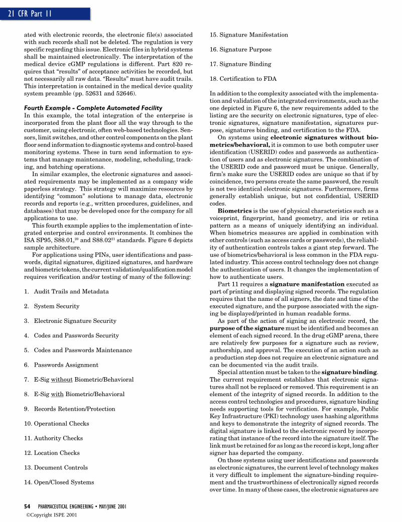
54 PHARMACEUTICAL ENGINEERING • MAY/JUNE 2001
21 CFR Part 11
ated with electronic records, the electronic file(s) associatedwith such records shall not be deleted. The regulation is veryspecific regarding this issue. Electronic files in hybrid systemsshall be maintained electronically. The interpretation of themedical device cGMP regulations is different. Part 820 re-quires that “results” of acceptance activities be recorded, butnot necessarily all raw data. “Results” must have audit trails.This interpretation is contained in the medical device qualitysystem preamble (pp. 52631 and 52646).
Fourth Example - Complete Automated FacilityIn this example, the total integration of the enterprise isincorporated from the plant floor all the way through to thecustomer, using electronic, often web-based technologies. Sen-sors, limit switches, and other control components on the plantfloor send information to diagnostic systems and control-basedmonitoring systems. These in turn send information to sys-tems that manage maintenance, modeling, scheduling, track-ing, and batching operations.
In similar examples, the electronic signatures and associ-ated requirements may be implemented as a company widepaperless strategy. This strategy will maximize resources byidentifying “common” solutions to manage data, electronicrecords and reports (e.g., written procedures, guidelines, anddatabases) that may be developed once for the company for allapplications to use.
This fourth example applies to the implementation of inte-grated enterprise and control environments. It combines theISA SP95, S88.01,20 and S88.0221 standards. Figure 6 depictssample architecture.
For applications using PINs, user identifications and pass-words, digital signatures, digitized signatures, and hardwareand biometric tokens, the current validation/qualification modelrequires verification and/or testing of many of the following:
1. Audit Trails and Metadata
2. System Security
3. Electronic Signature Security
4. Codes and Passwords Security
5. Codes and Passwords Maintenance
6. Passwords Assignment
7. E-Sig without Biometric/Behavioral
8. E-Sig with Biometric/Behavioral
9. Records Retention/Protection
10. Operational Checks
11. Authority Checks
12. Location Checks
13. Document Controls
14. Open/Closed Systems
15. Signature Manifestation
16. Signature Purpose
17. Signature Binding
18. Certification to FDA
In addition to the complexity associated with the implementa-tion and validation of the integrated environments, such as theone depicted in Figure 6, the new requirements added to thelisting are the security on electronic signatures, type of elec-tronic signatures, signature manifestation, signatures pur-pose, signatures binding, and certification to the FDA.
On systems using electronic signatures without bio-metrics/behavioral, it is common to use both computer useridentification (USERID) codes and passwords as authentica-tion of users and as electronic signatures. The combination ofthe USERID code and password must be unique. Generally,firm’s make sure the USERID codes are unique so that if bycoincidence, two persons create the same password, the resultis not two identical electronic signatures. Furthermore, firmsgenerally establish unique, but not confidential, USERIDcodes.
Biometrics is the use of physical characteristics such as avoiceprint, fingerprint, hand geometry, and iris or retinapattern as a means of uniquely identifying an individual.When biometrics measures are applied in combination withother controls (such as access cards or passwords), the reliabil-ity of authentication controls takes a giant step forward. Theuse of biometrics/behavioral is less common in the FDA regu-lated industry. This access control technology does not changethe authentication of users. It changes the implementation ofhow to authenticate users.
Part 11 requires a signature manifestation executed aspart of printing and displaying signed records. The regulationrequires that the name of all signers, the date and time of theexecuted signature, and the purpose associated with the sign-ing be displayed/printed in human readable forms.
As part of the action of signing an electronic record, thepurpose of the signature must be identified and becomes anelement of each signed record. In the drug cGMP arena, thereare relatively few purposes for a signature such as review,authorship, and approval. The execution of an action such asa production step does not require an electronic signature andcan be documented via the audit trails.
Special attention must be taken to the signature binding.The current requirement establishes that electronic signa-tures shall not be replaced or removed. This requirement is anelement of the integrity of signed records. In addition to theaccess control technologies and procedures, signature bindingneeds supporting tools for verification. For example, PublicKey Infrastructure (PKI) technology uses hashing algorithmsand keys to demonstrate the integrity of signed records. Thedigital signature is linked to the electronic record by incorpo-rating that instance of the record into the signature itself. Thelink must be retained for as long as the record is kept, long aftersigner has departed the company.
On those systems using user identifications and passwordsas electronic signatures, the current level of technology makesit very difficult to implement the signature-binding require-ment and the trustworthiness of electronically signed recordsover time. In many of these cases, the electronic signatures are
©Copyright ISPE 2001
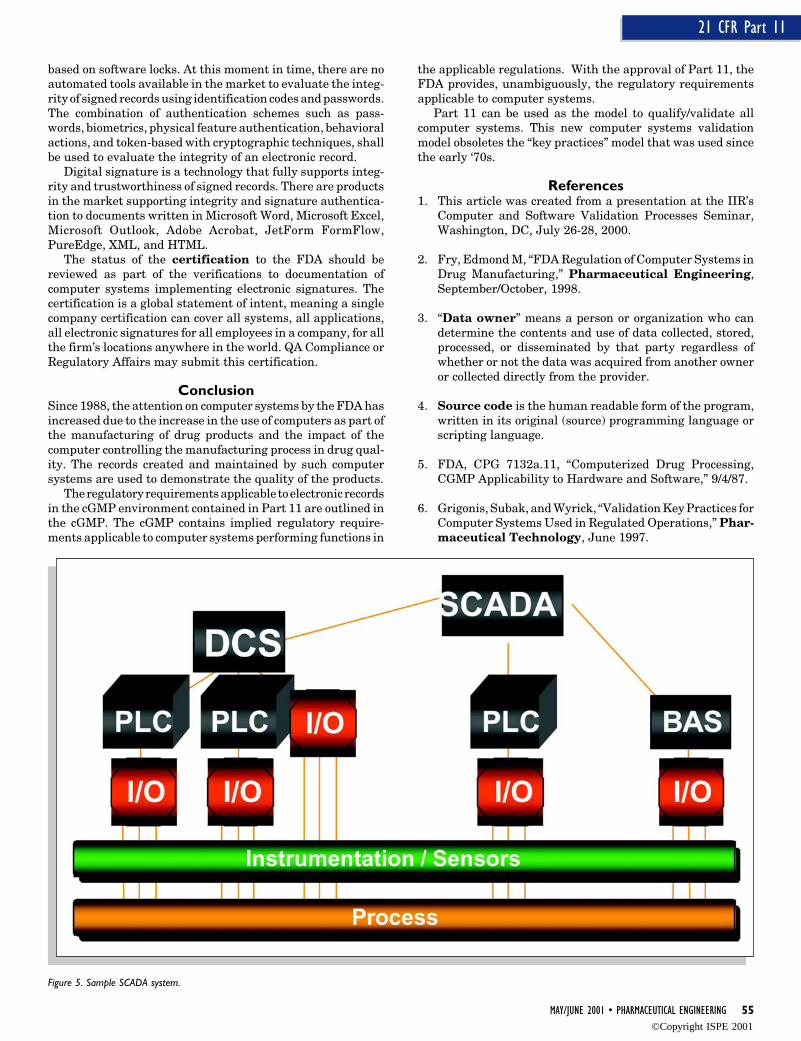
MAY/JUNE 2001 • PHARMACEUTICAL ENGINEERING 55
21 CFR Part 11
based on software locks. At this moment in time, there are noautomated tools available in the market to evaluate the integ-rity of signed records using identification codes and passwords.The combination of authentication schemes such as pass-words, biometrics, physical feature authentication, behavioralactions, and token-based with cryptographic techniques, shallbe used to evaluate the integrity of an electronic record.
Digital signature is a technology that fully supports integ-rity and trustworthiness of signed records. There are productsin the market supporting integrity and signature authentica-tion to documents written in Microsoft Word, Microsoft Excel,Microsoft Outlook, Adobe Acrobat, JetForm FormFlow,PureEdge, XML, and HTML.
The status of the certification to the FDA should bereviewed as part of the verifications to documentation ofcomputer systems implementing electronic signatures. Thecertification is a global statement of intent, meaning a singlecompany certification can cover all systems, all applications,all electronic signatures for all employees in a company, for allthe firm’s locations anywhere in the world. QA Compliance orRegulatory Affairs may submit this certification.
ConclusionSince 1988, the attention on computer systems by the FDA hasincreased due to the increase in the use of computers as part ofthe manufacturing of drug products and the impact of thecomputer controlling the manufacturing process in drug qual-ity. The records created and maintained by such computersystems are used to demonstrate the quality of the products.
The regulatory requirements applicable to electronic recordsin the cGMP environment contained in Part 11 are outlined inthe cGMP. The cGMP contains implied regulatory require-ments applicable to computer systems performing functions in
the applicable regulations. With the approval of Part 11, theFDA provides, unambiguously, the regulatory requirementsapplicable to computer systems.
Part 11 can be used as the model to qualify/validate allcomputer systems. This new computer systems validationmodel obsoletes the “key practices” model that was used sincethe early ‘70s.
References1. This article was created from a presentation at the IIR’s
Computer and Software Validation Processes Seminar,Washington, DC, July 26-28, 2000.
2. Fry, Edmond M, “FDA Regulation of Computer Systems inDrug Manufacturing,” Pharmaceutical Engineering,September/October, 1998.
3. “Data owner” means a person or organization who candetermine the contents and use of data collected, stored,processed, or disseminated by that party regardless ofwhether or not the data was acquired from another owneror collected directly from the provider.
4. Source code is the human readable form of the program,written in its original (source) programming language orscripting language.
5. FDA, CPG 7132a.11, “Computerized Drug Processing,CGMP Applicability to Hardware and Software,” 9/4/87.
6. Grigonis, Subak, and Wyrick, “Validation Key Practices forComputer Systems Used in Regulated Operations,” Phar-maceutical Technology, June 1997.
Figure 5. Sample SCADA system.
©Copyright ISPE 2001
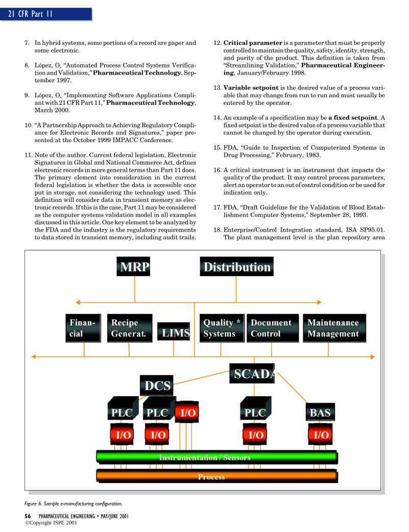
56 PHARMACEUTICAL ENGINEERING • MAY/JUNE 2001
21 CFR Part 11
7. In hybrid systems, some portions of a record are paper andsome electronic.
8. López, O, “Automated Process Control Systems Verifica-tion and Validation,” Pharmaceutical Technology, Sep-tember 1997.
9. López, O, “Implementing Software Applications Compli-ant with 21 CFR Part 11,” Pharmaceutical Technology,March 2000.
10. “A Partnership Approach to Achieving Regulatory Compli-ance for Electronic Records and Signatures,” paper pre-sented at the October 1999 IMPACC Conference.
11. Note of the author. Current federal legislation, ElectronicSignatures in Global and National Commerce Act, defineselectronic records in more general terms than Part 11 does.The primary element into consideration in the currentfederal legislation is whether the data is accessible onceput in storage, not considering the technology used. Thisdefinition will consider data in transient memory as elec-tronic records. If this is the case, Part 11 may be consideredas the computer systems validation model in all examplesdiscussed in this article. One key element to be analyzed bythe FDA and the industry is the regulatory requirementsto data stored in transient memory, including audit trails.
12. Critical parameter is a parameter that must be properlycontrolled to maintain the quality, safety, identity, strength,and purity of the product. This definition is taken from“Streamlining Validation,” Pharmaceutical Engineer-ing, January/February 1998.
13. Variable setpoint is the desired value of a process vari-able that may change from run to run and must usually beentered by the operator.
14. An example of a specification may be a fixed setpoint. Afixed setpoint is the desired value of a process variable thatcannot be changed by the operator during execution.
15. FDA, “Guide to Inspection of Computerized Systems inDrug Processing,” February, 1983.
16. A critical instrument is an instrument that impacts thequality of the product. It may control process parameters,alert an operator to an out of control condition or be used forindication only.
17. FDA, “Draft Guideline for the Validation of Blood Estab-lishment Computer Systems,” September 28, 1993.
18. Enterprise/Control Integration standard, ISA SP95.01.The plant management level is the plan repository area
Figure 6. Sample e-manufacturing configuration.
©Copyright ISPE 2001
MAY/JUNE 2001 • PHARMACEUTICAL ENGINEERING 57
21 CFR Part 11
(e.g., database server(s)) which unifies production, qualitycontrol, inventory, and warehouse data.
19. Metadata—Data describing stored data: that is, data de-scribing the structure, data elements, interrelationships,and other characteristics of electronic records, DOD 5014.2-STD, “Design Criteria Standard for Electronic RecordsManagement Software Applications.”
20. International Society of Measurement and Control (ISA)Batch Control Standard (S88.01) defines a common set ofmodels and terms for the design and operation of batchprocess control systems.
21. S88.02 standard includes a section that defines the com-munication requirements between the functions of recipeprocedure execution and equipment control.
About the AuthorOrlando López is a Computer Systems Validation Sr. Con-sultant for McNeil Consumer Products Company in Fort Wash-ington, PA. López’s experience includes managing a completevalidation medical device manufacturing facility, includingfacility, utilities, process equipment, and processes (formula-tion and fabrication). Special interest includes the GMP com-pliance issues on raw data, electronic records, electronic signa-ture and evaluation of legacy systems. He is a member of theISPE Computer System Validation Sub-Committee of theDelaware Valley Chapter. He can be reached at (215) 273-7903or be e-mail at [email protected].
McNeil Consumer Healthcare, 7050 Camp Hill Road, Ft.Washington, PA 19034.
©Copyright ISPE 2001
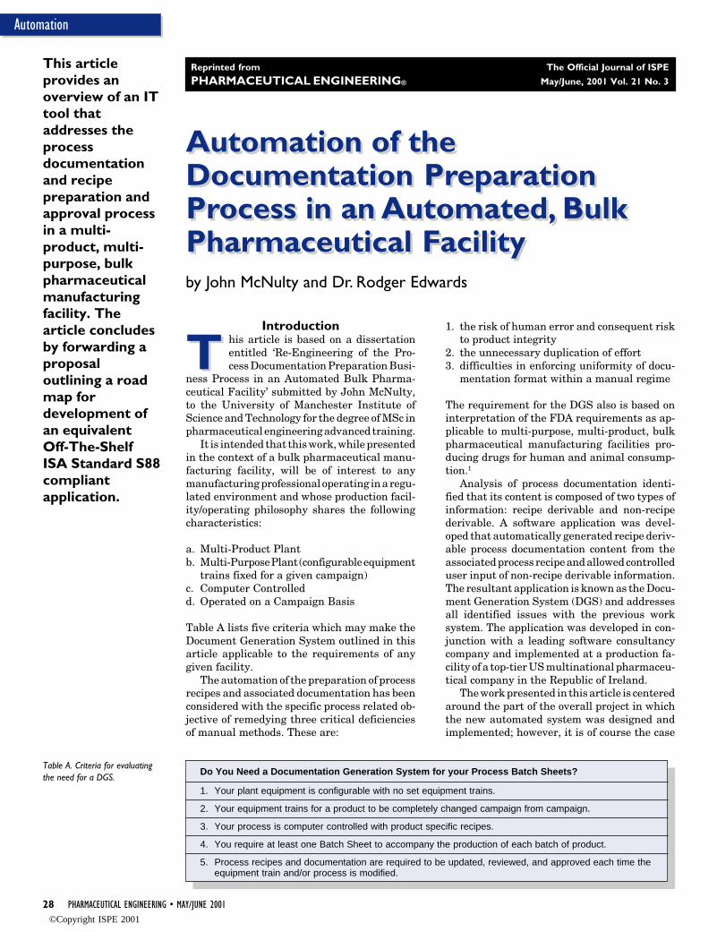
28 PHARMACEUTICAL ENGINEERING • MAY/JUNE 2001
Automation
Automation of theDocumentation PreparationProcess in an Automated, BulkPharmaceutical Facility
Automation of theDocumentation PreparationProcess in an Automated, BulkPharmaceutical Facility
T
by John McNulty and Dr. Rodger Edwards
This articleprovides anoverview of an ITtool thataddresses theprocessdocumentationand recipepreparation andapproval processin a multi-product, multi-purpose, bulkpharmaceuticalmanufacturingfacility. Thearticle concludesby forwarding aproposaloutlining a roadmap fordevelopment ofan equivalentOff-The-ShelfISA Standard S88compliantapplication.
Introduction
T his article is based on a dissertationentitled ‘Re-Engineering of the Pro-cess Documentation Preparation Busi-
ness Process in an Automated Bulk Pharma-ceutical Facility’ submitted by John McNulty,to the University of Manchester Institute ofScience and Technology for the degree of MSc inpharmaceutical engineering advanced training.
It is intended that this work, while presentedin the context of a bulk pharmaceutical manu-facturing facility, will be of interest to anymanufacturing professional operating in a regu-lated environment and whose production facil-ity/operating philosophy shares the followingcharacteristics:
a. Multi-Product Plantb. Multi-Purpose Plant (configurable equipment
trains fixed for a given campaign)c. Computer Controlledd. Operated on a Campaign Basis
Table A lists five criteria which may make theDocument Generation System outlined in thisarticle applicable to the requirements of anygiven facility.
The automation of the preparation of processrecipes and associated documentation has beenconsidered with the specific process related ob-jective of remedying three critical deficienciesof manual methods. These are:
1. the risk of human error and consequent riskto product integrity
2. the unnecessary duplication of effort3. difficulties in enforcing uniformity of docu-
mentation format within a manual regime
The requirement for the DGS also is based oninterpretation of the FDA requirements as ap-plicable to multi-purpose, multi-product, bulkpharmaceutical manufacturing facilities pro-ducing drugs for human and animal consump-tion.1
Analysis of process documentation identi-fied that its content is composed of two types ofinformation: recipe derivable and non-recipederivable. A software application was devel-oped that automatically generated recipe deriv-able process documentation content from theassociated process recipe and allowed controlleduser input of non-recipe derivable information.The resultant application is known as the Docu-ment Generation System (DGS) and addressesall identified issues with the previous worksystem. The application was developed in con-junction with a leading software consultancycompany and implemented at a production fa-cility of a top-tier US multinational pharmaceu-tical company in the Republic of Ireland.
The work presented in this article is centeredaround the part of the overall project in whichthe new automated system was designed andimplemented; however, it is of course the case
Do You Need a Documentation Generation System for your Process Batch Sheets?
1. Your plant equipment is configurable with no set equipment trains.
2. Your equipment trains for a product to be completely changed campaign from campaign.
3. Your process is computer controlled with product specific recipes.
4. You require at least one Batch Sheet to accompany the production of each batch of product.
5. Process recipes and documentation are required to be updated, reviewed, and approved each time theequipment train and/or process is modified.
Table A. Criteria for evaluatingthe need for a DGS.
Reprinted from The Official Journal of ISPE
PHARMACEUTICAL ENGINEERING® May/June, 2001 Vol. 21 No. 3
©Copyright ISPE 2001
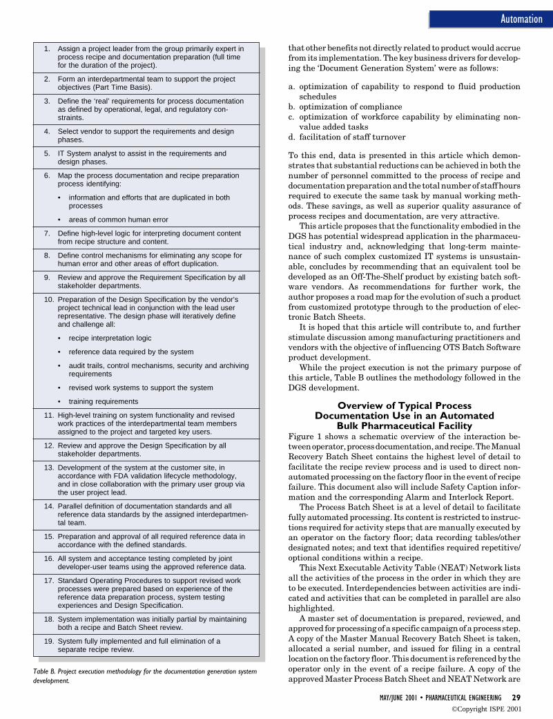
MAY/JUNE 2001 • PHARMACEUTICAL ENGINEERING 29
Automation
that other benefits not directly related to product would accruefrom its implementation. The key business drivers for develop-ing the ‘Document Generation System’ were as follows:
a. optimization of capability to respond to fluid productionschedules
b. optimization of compliancec. optimization of workforce capability by eliminating non-
value added tasksd. facilitation of staff turnover
To this end, data is presented in this article which demon-strates that substantial reductions can be achieved in both thenumber of personnel committed to the process of recipe anddocumentation preparation and the total number of staff hoursrequired to execute the same task by manual working meth-ods. These savings, as well as superior quality assurance ofprocess recipes and documentation, are very attractive.
This article proposes that the functionality embodied in theDGS has potential widespread application in the pharmaceu-tical industry and, acknowledging that long-term mainte-nance of such complex customized IT systems is unsustain-able, concludes by recommending that an equivalent tool bedeveloped as an Off-The-Shelf product by existing batch soft-ware vendors. As recommendations for further work, theauthor proposes a road map for the evolution of such a productfrom customized prototype through to the production of elec-tronic Batch Sheets.
It is hoped that this article will contribute to, and furtherstimulate discussion among manufacturing practitioners andvendors with the objective of influencing OTS Batch Softwareproduct development.
While the project execution is not the primary purpose ofthis article, Table B outlines the methodology followed in theDGS development.
Overview of Typical ProcessDocumentation Use in an Automated
Bulk Pharmaceutical FacilityFigure 1 shows a schematic overview of the interaction be-tween operator, process documentation, and recipe. The ManualRecovery Batch Sheet contains the highest level of detail tofacilitate the recipe review process and is used to direct non-automated processing on the factory floor in the event of recipefailure. This document also will include Safety Caption infor-mation and the corresponding Alarm and Interlock Report.
The Process Batch Sheet is at a level of detail to facilitatefully automated processing. Its content is restricted to instruc-tions required for activity steps that are manually executed byan operator on the factory floor; data recording tables/otherdesignated notes; and text that identifies required repetitive/optional conditions within a recipe.
This Next Executable Activity Table (NEAT) Network listsall the activities of the process in the order in which they areto be executed. Interdependencies between activities are indi-cated and activities that can be completed in parallel are alsohighlighted.
A master set of documentation is prepared, reviewed, andapproved for processing of a specific campaign of a process step.A copy of the Master Manual Recovery Batch Sheet is taken,allocated a serial number, and issued for filing in a centrallocation on the factory floor. This document is referenced by theoperator only in the event of a recipe failure. A copy of theapproved Master Process Batch Sheet and NEAT Network are
Table B. Project execution methodology for the documentation generation systemdevelopment.
1. Assign a project leader from the group primarily expert inprocess recipe and documentation preparation (full timefor the duration of the project).
2. Form an interdepartmental team to support the projectobjectives (Part Time Basis).
3. Define the ‘real’ requirements for process documentationas defined by operational, legal, and regulatory con-straints.
4. Select vendor to support the requirements and designphases.
5. IT System analyst to assist in the requirements anddesign phases.
6. Map the process documentation and recipe preparationprocess identifying:
• information and efforts that are duplicated in bothprocesses
• areas of common human error
7. Define high-level logic for interpreting document contentfrom recipe structure and content.
8. Define control mechanisms for eliminating any scope forhuman error and other areas of effort duplication.
9. Review and approve the Requirement Specification by allstakeholder departments.
10. Preparation of the Design Specification by the vendor’sproject technical lead in conjunction with the lead userrepresentative. The design phase will iteratively defineand challenge all:
• recipe interpretation logic
• reference data required by the system
• audit trails, control mechanisms, security and archivingrequirements
• revised work systems to support the system
• training requirements
11. High-level training on system functionality and revisedwork practices of the interdepartmental team membersassigned to the project and targeted key users.
12. Review and approve the Design Specification by allstakeholder departments.
13. Development of the system at the customer site, inaccordance with FDA validation lifecycle methodology,and in close collaboration with the primary user group viathe user project lead.
14. Parallel definition of documentation standards and allreference data standards by the assigned interdepartmen-tal team.
15. Preparation and approval of all required reference data inaccordance with the defined standards.
16. All system and acceptance testing completed by jointdeveloper-user teams using the approved reference data.
17. Standard Operating Procedures to support revised workprocesses were prepared based on experience of thereference data preparation process, system testingexperiences and Design Specification.
18. System implementation was initially partial by maintainingboth a recipe and Batch Sheet review.
19. System fully implemented and full elimination of aseparate recipe review.
©Copyright ISPE 2001
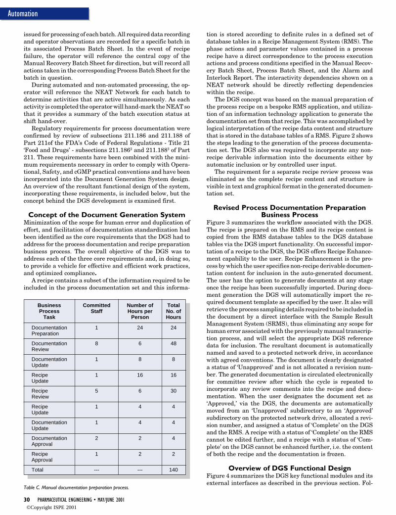
30 PHARMACEUTICAL ENGINEERING • MAY/JUNE 2001
Automation
issued for processing of each batch. All required data recordingand operator observations are recorded for a specific batch inits associated Process Batch Sheet. In the event of recipefailure, the operator will reference the central copy of theManual Recovery Batch Sheet for direction, but will record allactions taken in the corresponding Process Batch Sheet for thebatch in question.
During automated and non-automated processing, the op-erator will reference the NEAT Network for each batch todetermine activities that are active simultaneously. As eachactivity is completed the operator will hand-mark the NEAT sothat it provides a summary of the batch execution status atshift hand-over.
Regulatory requirements for process documentation wereconfirmed by review of subsections 211.186 and 211.188 ofPart 211of the FDA’s Code of Federal Regulations - Title 21‘Food and Drugs’ - subsections 211.1862 and 211.1883 of Part211. These requirements have been combined with the mini-mum requirements necessary in order to comply with Opera-tional, Safety, and cGMP practical conventions and have beenincorporated into the Document Generation System design.An overview of the resultant functional design of the system,incorporating these requirements, is included below, but theconcept behind the DGS development is examined first.
Concept of the Document Generation SystemMinimization of the scope for human error and duplication ofeffort, and facilitation of documentation standardization hadbeen identified as the core requirements that the DGS had toaddress for the process documentation and recipe preparationbusiness process. The overall objective of the DGS was toaddress each of the three core requirements and, in doing so,to provide a vehicle for effective and efficient work practices,and optimized compliance.
A recipe contains a subset of the information required to beincluded in the process documentation set and this informa-
tion is stored according to definite rules in a defined set ofdatabase tables in a Recipe Management System (RMS). Thephase actions and parameter values contained in a processrecipe have a direct correspondence to the process executionactions and process conditions specified in the Manual Recov-ery Batch Sheet, Process Batch Sheet, and the Alarm andInterlock Report. The interactivity dependencies shown on aNEAT network should be directly reflecting dependencieswithin the recipe.
The DGS concept was based on the manual preparation ofthe process recipe on a bespoke RMS application, and utiliza-tion of an information technology application to generate thedocumentation set from that recipe. This was accomplished bylogical interpretation of the recipe data content and structurethat is stored in the database tables of a RMS. Figure 2 showsthe steps leading to the generation of the process documenta-tion set. The DGS also was required to incorporate any non-recipe derivable information into the documents either byautomatic inclusion or by controlled user input.
The requirement for a separate recipe review process waseliminated as the complete recipe content and structure isvisible in text and graphical format in the generated documen-tation set.
Revised Process Documentation PreparationBusiness Process
Figure 3 summarizes the workflow associated with the DGS.The recipe is prepared on the RMS and its recipe content iscopied from the RMS database tables to the DGS databasetables via the DGS import functionality. On successful impor-tation of a recipe to the DGS, the DGS offers Recipe Enhance-ment capability to the user. Recipe Enhancement is the pro-cess by which the user specifies non-recipe derivable documen-tation content for inclusion in the auto-generated document.The user has the option to generate documents at any stageonce the recipe has been successfully imported. During docu-ment generation the DGS will automatically import the re-quired document template as specified by the user. It also willretrieve the process sampling details required to be included inthe document by a direct interface with the Sample ResultManagement System (SRMS), thus eliminating any scope forhuman error associated with the previously manual transcrip-tion process, and will select the appropriate DGS referencedata for inclusion. The resultant document is automaticallynamed and saved to a protected network drive, in accordancewith agreed conventions. The document is clearly designateda status of ‘Unapproved’ and is not allocated a revision num-ber. The generated documentation is circulated electronicallyfor committee review after which the cycle is repeated toincorporate any review comments into the recipe and docu-mentation. When the user designates the document set as‘Approved,’ via the DGS, the documents are automaticallymoved from an ‘Unapproved’ subdirectory to an ‘Approved’subdirectory on the protected network drive, allocated a revi-sion number, and assigned a status of ‘Complete’ on the DGSand the RMS. A recipe with a status of ‘Complete’ on the RMScannot be edited further, and a recipe with a status of ‘Com-plete’ on the DGS cannot be enhanced further, i.e. the contentof both the recipe and the documentation is frozen.
Overview of DGS Functional DesignFigure 4 summarizes the DGS key functional modules and itsexternal interfaces as described in the previous section. Fol-
Table C. Manual documentation preparation process.
Business Committed Number of TotalProcess Staff Hours per No. of
Task Person Hours
Documentation 1 24 24Preparation
Documentation 8 6 48Review
Documentation 1 8 8Update
Recipe 1 16 16Update
Recipe 5 6 30Review
Recipe 1 4 4Update
Documentation 1 4 4Update
Documentation 2 2 4Approval
Recipe 1 2 2Approval
Total --- --- 140
©Copyright ISPE 2001
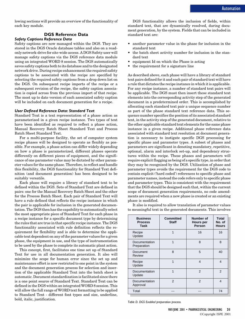
MAY/JUNE 2001 • PHARMACEUTICAL ENGINEERING 31
Automation
lowing sections will provide an overview of the functionality ofeach key module.
DGS Reference DataSafety Captions Reference DataSafety captions are now managed within the DGS. They arestored in the DGS Oracle database tables and also on a read-only network-drive for site-wide access. A DGS Safety user willmanage safety captions via the DGS reference data moduleusing an integrated WORD 8 session. The DGS automaticallysaves safety captions both to its database and to the designatednetwork drive. During recipe enhancement the required safetycaptions to be associated with the recipe are specified byselecting the required safety captions from a drop down list onthe DGS. On subsequent recipe imports of the recipe or asubsequent revision of the recipe, the safety caption associa-tion is copied across from the previous import of that recipe.The most up to date version of each associated safety captionwill be included on each document generation for a recipe.
User Defined Reference Data: Standard TextStandard Text is a text representation of a phase action asparameterized in a given recipe instance. Two types of texthave been identified as required to reflect a phase action,Manual Recovery Batch Sheet Standard Text and ProcessBatch Sheet Standard Text.
For a multi-purpose facility, the set of computer systemrecipe phases will be designed to operate as flexibly as pos-sible. For example, a phase action can differ widely dependingon how a phase is parameterized, different phases operatedifferently on different pieces of equipment, and the signifi-cance of one parameter value may be dictated by other param-eter values for the same phase. Therefore, to reflect and handlethis flexibility, the DGS functionality for Standard Text defi-nition (and document generation) has been designed to besuitably versatile.
Each phase will require a library of standard text to bedefined within the DGS. Sets of Standard Text are defined inpairs: one for the Manual Recovery Batch Sheet and the otherfor the Process Batch Sheet. Each pair of Standard Text willhave a rule defined that reflects the recipe instance in whichthe pair is applicable for inclusion in the generated documen-tation. The DGS then has the capability to automatically selectthe most appropriate piece of Standard Text for each phase ina recipe instance for a specific document type by determiningthe rules that are true in that specific recipe instance. The DGSfunctionality associated with rule definition reflects the re-quirement for flexibility and is able to determine the appli-cable text dependent on any of the parameter values for a givenphase, the equipment in use, and the type of instrumentationto be used by the phase to complete its automatic plant action.
This concept, first, facilitates one time set up of StandardText for use in all documentation generation. It also willminimize the scope for human error since the set up andmaintenance effort is now restricted to one point in the systemand the document generation process for selection and inser-tion of the applicable Standard Text into the batch sheet isautomatic. Document standardization is facilitated since thereis a one point source of Standard Text. Standard Text can bedefined in the DGS within an integrated WORD 8 session. Thiswill allow the full range of WORD text formatting to be appliedto Standard Text - different font types and size, underline,bold, italic, justification.
DGS functionality allows the inclusion of fields, withinstandard text, that are dynamically resolved, during docu-ment generation, by the system. Fields that can be included instandard text are:
• another parameter value in the phase for inclusion in thestandard text
• the batch sheet activity number for inclusion in the stan-dard text
• equipment Id on which the Phase is acting• the requirement for a signature line
As described above, each phase will have a library of standardtext pairs defined for it and each pair of standard text will havea rule that dictates the recipe instance in which it is applicable.For any recipe instance, a number of standard text pairs willbe applicable. The DGS must then insert these standard textelements into the corresponding activity step of the generateddocument in a predetermined order. This is accomplished byallocating each standard text pair a unique sequence numberas part of the phase standard text reference data. This se-quence number specifies the position of its associated standardtext, in the activity step of the generated document, relative tothe other applicable standard text elements for the same phaseinstance in a given recipe. Additional phase reference dataassociated with standard text resolution at document genera-tion is necessary to instigate specific DGS processing forspecific phase and parameter types. A subset of phases andparameters are significant in denoting mandatory, repetitive,optional, alarm and interlock set-up, and dependency struc-tures within the recipe. These phases and parameters willrequire explicit flagging as being of a specific type, in order thatthey may be recognized by the DGS. Utilization of phase andparameter types avoids the requirement for the DGS code tocontain explicit (‘hard coded’) references to specific phase andparameter names, instead the code refers only to specific phaseand parameter types. This is consistent with the requirementthat the DGS should be designed such that, within the currentscope of document generation requirements, no code amend-ments are required when a new phase is created or an existingphase is modified.
It also is required to allow translation of parameter valuesto meaningful text in the generated documents. This involves
Business Committed Number of TotalProcess Staff Hours per No. of
Task Person Hours
Recipe 1 16 16Update
Documentation 1 8 8Preparation
Document 8 5 40Review
Recipe 1 4 4Update
Documentation 1 2 2Update
Documentation 2 2 4Approval
Total --- --- 74
Table D. DGS Enabled preparation process.
©Copyright ISPE 2001
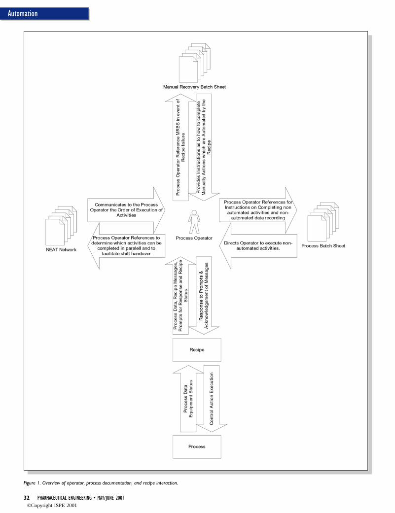
32 PHARMACEUTICAL ENGINEERING • MAY/JUNE 2001
Automation
Figure 1. Overview of operator, process documentation, and recipe interaction.
©Copyright ISPE 2001
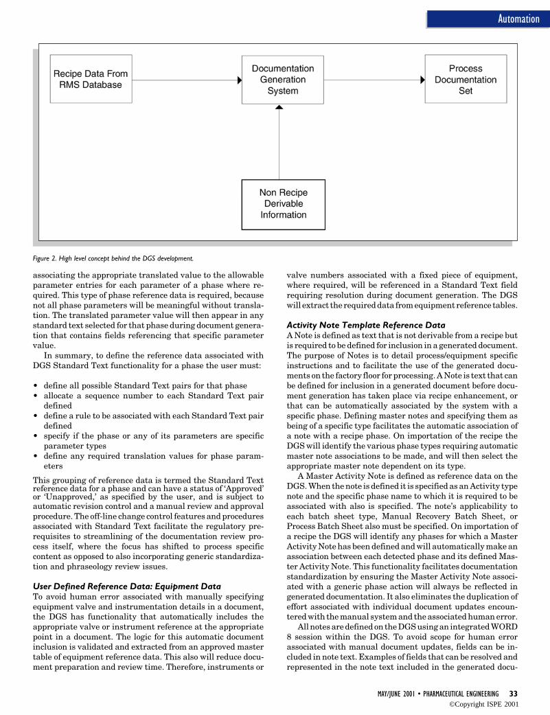
MAY/JUNE 2001 • PHARMACEUTICAL ENGINEERING 33
Automation
associating the appropriate translated value to the allowableparameter entries for each parameter of a phase where re-quired. This type of phase reference data is required, becausenot all phase parameters will be meaningful without transla-tion. The translated parameter value will then appear in anystandard text selected for that phase during document genera-tion that contains fields referencing that specific parametervalue.
In summary, to define the reference data associated withDGS Standard Text functionality for a phase the user must:
• define all possible Standard Text pairs for that phase• allocate a sequence number to each Standard Text pair
defined• define a rule to be associated with each Standard Text pair
defined• specify if the phase or any of its parameters are specific
parameter types• define any required translation values for phase param-
eters
This grouping of reference data is termed the Standard Textreference data for a phase and can have a status of ‘Approved’or ‘Unapproved,’ as specified by the user, and is subject toautomatic revision control and a manual review and approvalprocedure. The off-line change control features and proceduresassociated with Standard Text facilitate the regulatory pre-requisites to streamlining of the documentation review pro-cess itself, where the focus has shifted to process specificcontent as opposed to also incorporating generic standardiza-tion and phraseology review issues.
User Defined Reference Data: Equipment DataTo avoid human error associated with manually specifyingequipment valve and instrumentation details in a document,the DGS has functionality that automatically includes theappropriate valve or instrument reference at the appropriatepoint in a document. The logic for this automatic documentinclusion is validated and extracted from an approved mastertable of equipment reference data. This also will reduce docu-ment preparation and review time. Therefore, instruments or
valve numbers associated with a fixed piece of equipment,where required, will be referenced in a Standard Text fieldrequiring resolution during document generation. The DGSwill extract the required data from equipment reference tables.
Activity Note Template Reference DataA Note is defined as text that is not derivable from a recipe butis required to be defined for inclusion in a generated document.The purpose of Notes is to detail process/equipment specificinstructions and to facilitate the use of the generated docu-ments on the factory floor for processing. A Note is text that canbe defined for inclusion in a generated document before docu-ment generation has taken place via recipe enhancement, orthat can be automatically associated by the system with aspecific phase. Defining master notes and specifying them asbeing of a specific type facilitates the automatic association ofa note with a recipe phase. On importation of the recipe theDGS will identify the various phase types requiring automaticmaster note associations to be made, and will then select theappropriate master note dependent on its type.
A Master Activity Note is defined as reference data on theDGS. When the note is defined it is specified as an Activity typenote and the specific phase name to which it is required to beassociated with also is specified. The note’s applicability toeach batch sheet type, Manual Recovery Batch Sheet, orProcess Batch Sheet also must be specified. On importation ofa recipe the DGS will identify any phases for which a MasterActivity Note has been defined and will automatically make anassociation between each detected phase and its defined Mas-ter Activity Note. This functionality facilitates documentationstandardization by ensuring the Master Activity Note associ-ated with a generic phase action will always be reflected ingenerated documentation. It also eliminates the duplication ofeffort associated with individual document updates encoun-tered with the manual system and the associated human error.
All notes are defined on the DGS using an integrated WORD8 session within the DGS. To avoid scope for human errorassociated with manual document updates, fields can be in-cluded in note text. Examples of fields that can be resolved andrepresented in the note text included in the generated docu-
Figure 2. High level concept behind the DGS development.
©Copyright ISPE 2001
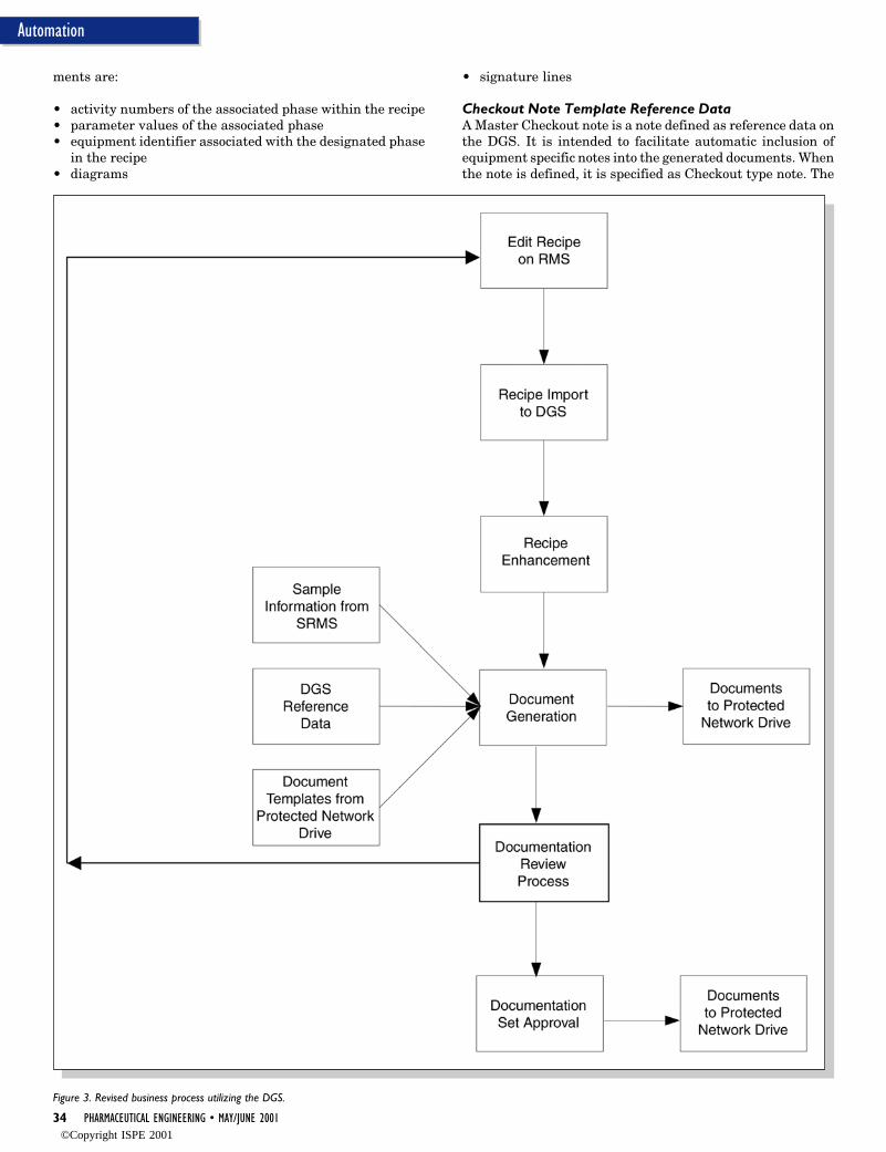
34 PHARMACEUTICAL ENGINEERING • MAY/JUNE 2001
Automation
Figure 3. Revised business process utilizing the DGS.
ments are:
• activity numbers of the associated phase within the recipe• parameter values of the associated phase• equipment identifier associated with the designated phase
in the recipe• diagrams
• signature lines
Checkout Note Template Reference DataA Master Checkout note is a note defined as reference data onthe DGS. It is intended to facilitate automatic inclusion ofequipment specific notes into the generated documents. Whenthe note is defined, it is specified as Checkout type note. The
©Copyright ISPE 2001
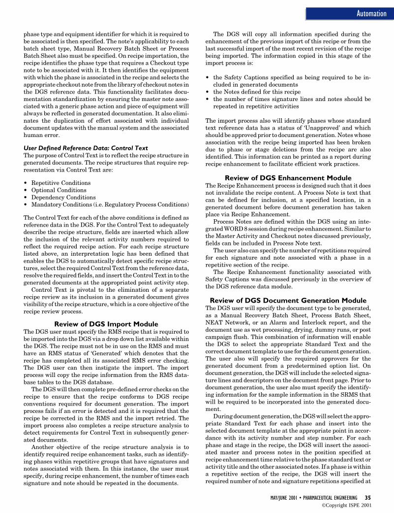
MAY/JUNE 2001 • PHARMACEUTICAL ENGINEERING 35
Automation
phase type and equipment identifier for which it is required tobe associated is then specified. The note’s applicability to eachbatch sheet type, Manual Recovery Batch Sheet or ProcessBatch Sheet also must be specified. On recipe importation, therecipe identifies the phase type that requires a Checkout typenote to be associated with it. It then identifies the equipmentwith which the phase is associated in the recipe and selects theappropriate checkout note from the library of checkout notes inthe DGS reference data. This functionality facilitates docu-mentation standardization by ensuring the master note asso-ciated with a generic phase action and piece of equipment willalways be reflected in generated documentation. It also elimi-nates the duplication of effort associated with individualdocument updates with the manual system and the associatedhuman error.
User Defined Reference Data: Control TextThe purpose of Control Text is to reflect the recipe structure ingenerated documents. The recipe structures that require rep-resentation via Control Text are:
• Repetitive Conditions• Optional Conditions• Dependency Conditions• Mandatory Conditions (i.e. Regulatory Process Conditions)
The Control Text for each of the above conditions is defined asreference data in the DGS. For the Control Text to adequatelydescribe the recipe structure, fields are inserted which allowthe inclusion of the relevant activity numbers required toreflect the required recipe action. For each recipe structurelisted above, an interpretation logic has been defined thatenables the DGS to automatically detect specific recipe struc-tures, select the required Control Text from the reference data,resolve the required fields, and insert the Control Text in to thegenerated documents at the appropriated point activity step.
Control Text is pivotal to the elimination of a separaterecipe review as its inclusion in a generated document givesvisibility of the recipe structure, which is a core objective of therecipe review process.
Review of DGS Import ModuleThe DGS user must specify the RMS recipe that is required tobe imported into the DGS via a drop down list available withinthe DGS. The recipe must not be in use on the RMS and musthave an RMS status of ‘Generated’ which denotes that therecipe has completed all its associated RMS error checking.The DGS user can then instigate the import. The importprocess will copy the recipe information from the RMS data-base tables to the DGS database.
The DGS will then complete pre-defined error checks on therecipe to ensure that the recipe conforms to DGS recipeconventions required for document generation. The importprocess fails if an error is detected and it is required that therecipe be corrected in the RMS and the import retried. Theimport process also completes a recipe structure analysis todetect requirements for Control Text in subsequently gener-ated documents.
Another objective of the recipe structure analysis is toidentify required recipe enhancement tasks, such as identify-ing phases within repetitive groups that have signatures andnotes associated with them. In this instance, the user mustspecify, during recipe enhancement, the number of times eachsignature and note should be repeated in the documents.
The DGS will copy all information specified during theenhancement of the previous import of this recipe or from thelast successful import of the most recent revision of the recipebeing imported. The information copied in this stage of theimport process is:
• the Safety Captions specified as being required to be in-cluded in generated documents
• the Notes defined for this recipe• the number of times signature lines and notes should be
repeated in repetitive activities
The import process also will identify phases whose standardtext reference data has a status of ‘Unapproved’ and whichshould be approved prior to document generation. Notes whoseassociation with the recipe being imported has been brokendue to phase or stage deletions from the recipe are alsoidentified. This information can be printed as a report duringrecipe enhancement to facilitate efficient work practices.
Review of DGS Enhancement ModuleThe Recipe Enhancement process is designed such that it doesnot invalidate the recipe content. A Process Note is text thatcan be defined for inclusion, at a specified location, in agenerated document before document generation has takenplace via Recipe Enhancement.
Process Notes are defined within the DGS using an inte-grated WORD 8 session during recipe enhancement. Similar tothe Master Activity and Checkout notes discussed previously,fields can be included in Process Note text.
The user also can specify the number of repetitions requiredfor each signature and note associated with a phase in arepetitive section of the recipe.
The Recipe Enhancement functionality associated withSafety Captions was discussed previously in the overview ofthe DGS reference data module.
Review of DGS Document Generation ModuleThe DGS user will specify the document type to be generated,as a Manual Recovery Batch Sheet, Process Batch Sheet,NEAT Network, or an Alarm and Interlock report, and thedocument use as wet processing, drying, dummy runs, or postcampaign flush. This combination of information will enablethe DGS to select the appropriate Standard Text and thecorrect document template to use for the document generation.The user also will specify the required approvers for thegenerated document from a predetermined option list. Ondocument generation, the DGS will include the selected signa-ture lines and descriptors on the document front page. Prior todocument generation, the user also must specify the identify-ing information for the sample information in the SRMS thatwill be required to be incorporated into the generated docu-ment.
During document generation, the DGS will select the appro-priate Standard Text for each phase and insert into theselected document template at the appropriate point in accor-dance with its activity number and step number. For eachphase and stage in the recipe, the DGS will insert the associ-ated master and process notes in the position specified atrecipe enhancement time relative to the phase standard text oractivity title and the other associated notes. If a phase is withina repetitive section of the recipe, the DGS will insert therequired number of note and signature repetitions specified at
©Copyright ISPE 2001

36 PHARMACEUTICAL ENGINEERING • MAY/JUNE 2001
Automation
recipe enhancement time. All fields in applicable standard textand notes will be resolved by the DGS prior to insertion in theWORD document being generated. Resolution of fields speci-fying process sample information will be retrieved directlyfrom the SRMS database and inserted into the appropriatelocation in the document.
The appropriate Control Text will be selected and includedin the document at the appropriate location based on the datagenerated by the recipe import analysis. For each SafetyCaption specified as being required for inclusion at recipeenhancement time, the DGS will retrieve the most recentrevision from the DGS reference data database and insert in tothe document.
The resultant document is automatically named and savedto a protected network drive, in accordance with agreed con-ventions. The document is clearly designated a status of‘Unapproved’ and is not allocated a revision number. Anancillary report is automatically generated by the DGS thatwill identify all notes whose content has changed since the lastdocumentation revision. This will facilitate the review andapproval process. When the user designates the document setas ‘Approved’ via the DGS, the documents are automaticallymoved from an ‘Unapproved’ subdirectory to an ‘Approved’subdirectory on the protected network drive, allocated a revi-sion number, and designated a status of ‘Approved’ on theDGS.
Business BenefitsThis article attempts to present the product related aspects ofthe development and implementation of the automated sys-tem; however, there are other obvious business benefits be-yond the eradication of the three key deficiencies of the manualapproach. In particular, the use of automation would be ex-pected to have implications for the use of human resources.
Table C presents an analysis of the human resourcescommitted to a manual documentation preparation process,based on data collected prior to the commencement of the
automation project. Table D presents data for the automatedpreparation of the same recipe collected after the system hadbeen commissioned. In both cases, the human resource com-mitments map on to the cycle of the process in question, ratherthan representing the total commitment to a particular type ofactivity, for example recipe update.
There are several striking features when the two tables arecompared. First, as shown previously in this article, the num-ber of steps in the process is seven for the automated case,compared to nine for the manual case, showing that a degreeof simplification has been achieved.
Comparison of the human resource commitments for themanual and automated cases also show reduction. For the caseof committed staff, reductions of 33% are achieved. Actualhours of effort are reduced by almost 50%. This is due not onlyto the elimination of process steps, but also because somesteps, for example recipe update, take much less time. Savingsof this magnitude are highly significant, and could possibly beimproved by further improvements in software.
ConclusionsThe introduction of the DGS has provided a successful resolu-tion of three key issues associated with the manual systempreviously used. The DGS also has resulted in productivityincreases in the recipe and documentation preparation andapproval processes. This enhances the facility’s response capa-bility to rapid production schedule changes and new productintroductions; anticipated to be an increasing trend in thepharmaceutical industry in the next decade. See Tables C andD for a comparison of the manual process versus the revisedDGS enabled system.
However, a note of caution must be struck. From previousexperience of bespoke applications (bespoke in this contextmeans specific piece of software written for a given process, asopposed to generic), it has been concluded that the viability oflong-term support of the system is limited, due to technologicalobsolescence and specific knowledge dilution, due to IT sup-port staff turnover.
Predicted industry trends indicate a shift toward the use ofmulti-purpose, multi-product, bulk pharmaceutical manufac-turing facilities. On this basis, it is likely that there is anindustry wide opportunity for the widespread introduction ofDGS type applications. The bespoke DGS described in thisarticle could be considered as crystallizing industry require-ments for an Off-The-Shelf (OTS) DGS application. The devel-opment of ISA standard S88, for application to Recipe Manage-ment Systems developed for both primary and secondarymanufacturing facilities, has afforded the opportunity for thedevelopment of an OTS DGS system interfacing with an S88
Figure 4. Overview of DGS functional design.
Figure 5. Interim solution in migration towards total use of OTS applications.
©Copyright ISPE 2001
MAY/JUNE 2001 • PHARMACEUTICAL ENGINEERING 37
Automation
compliant RMS.Given the industry wide applicability of a DGS type appli-
cation, the technical feasibility demonstrated by the DGS andthe emergence of S88 compliant recipe management products,it can be concluded that the long term solution to process recipeand documentation requirements can best be served by thedevelopment of an OTS DGS type application by a specialistbatch management vendor, rather than all operating sitespressing ahead with their own bespoke solutions. Industrytrends will hopefully mean that it will be economically viablefor software vendors to meet the need.
Recommendations for Further WorkThe ISA standard for Recipe Management systems S88.014
has been approved since 1995 and several S88.01 compliantOTS recipe management systems are available on the market.These applications combine the off line recipe editing capabili-ties and on-line recipe execution within one package. A highlevel assessment of the available S88 compliant OTS RMSapplications is that they are extremely user friendly andpowerful; however, they lack the facility to generate a docu-ment to facilitate a review process and have poor reciperevision control and change auditing capabilities.
ISA standard S88.025 outlines an international standardthat specifies recipe database table structures to which anyS88 compliant system should be capable of exporting a recipe.These tables are known as Data Exchange Tables. In consid-ering a migration route from a work process based on whollybespoke applications to one based solely on OTS applications,several options were considered. One option considered was
the implementation of an OTS S88 compliant RMS applicationand the development of bespoke applications that interrogatethe Data Exchange Tables and generate recipe review docu-mentation and recipe change auditing reports. This option(Figure 5) would be expensive, as a short term solution, as theapplication code of the current version of the DGS is based oninterpretation of the bespoke RMS database tables. To reviseit to interpret the S88.02, data exchange tables would requirean almost total rewrite. This migration option is not recom-mended, since it will result in the development and mainte-nance costs associated with the ancillary bespoke applications.The emphasis should be on development of a sustainable long-term solution as outlined below.
With the issuing of FDA’s 21 CFR Part 116, detailing itsruling on electronic signatures, the industry trend in themedium term will be toward electronic batch sheets and batchrecords. The ideal conceptual model based on requirementscrystallized by the bespoke RMS and DGS developments at amulti-purpose, multi-product, bulk pharmaceutical manufac-turing site is illustrated in Figure 6. This model uses DGScapabilities to generate documentation to support a reviewprocess. The DGS functionality also could be modified todynamically resolve text for batch sheet on glass instructionsto support fully sequenced or manual recovery actions asapplicable. The text presented ‘on glass’ to the operator wouldinclude standard text representing phase action, safety in-structions, and process specific instructions. No available OTSapplication has the capability to represent in text form thephase action nor the required operation instruction based on
Figure 6. Proposed product model addressing Process Recipe Management and Execution in a paperless environment.
©Copyright ISPE 2001
38 PHARMACEUTICAL ENGINEERING • MAY/JUNE 2001
Automation
the phase action. This functionality has been developed andpiloted in the DGS application development.
References1. Re-Engineering of the Process Documentation Preparation
Business Process in an Automated Bulk PharmaceuticalFacility. A thesis submitted to the University of Manches-ter Institute of Science and Technology for the degree ofMSc, by J.McNulty, May 2000.
2. Code of Federal Regulations, Food and Drug Administra-tion, 21 CFR Part 210 & 211 Section 211.186, April 2000.
3. Code of Federal Regulations, Food and Drug Administra-tion, 21 CFR Part 210 & 211 Section 211.188, April 2000.
4. ISA-S88.01-1995 Batch Control: Part 1: Models and Termi-nology (Approved October 1995).
5. ISA-S88.02-1999 Batch Control: Part 2 (Draft).6. Code of Federal Regulations, Food and Drug Administra-
tion, 21 CFR Part 11, ‘FDA Final Rule, Electronic Records& Electronic Signatures’, August 1997.
About the AuthorsJohn McNulty BEng MSc is a graduate of chemical engi-neering from The Queen’s University of Belfast, NorthernIreland (1990). McNulty has broad operational experience inbulk pharmaceutical manufacturing having worked with aleading US multi-national pharmaceutical company at theirmulti-product, multi-purpose manufacturing facility in Ire-land from 1990 to 2000. McNulty’s experience encompasses:new product and technology introduction projects, productionengineering support, participation on a team responsible forthe introduction of a new DGS system, and consequentreengineering of associated business processes. Most recently,he has been responsible for leading the design and implemen-tation of the automated Document Generation System de-
scribed in this article and has participated in discussions withleading Batch Software vendors with a view to influencingtheir product features in the areas of recipe and documenta-tion management. Having completed his MSc in pharmaceuti-cal engineering advanced training by distance learning fromUMIST, McNulty is currently studying full time at the LondonBusiness School for an MBA and can be contacted by e-mail [email protected].
Rodger Edwards BSc MSc PhD CEng MCIBSE graduatedwith a BSc (Honors) in metallurgy and materials science fromthe joint UMIST/University of Manchester Department ofMetallurgy in 1979, and then spent three years as a researchstudent in the same department, his research area being thethermophysical properties of liquid metals. He joined theDepartment of Building Engineering at UMIST as a researchassistant in 1983 with his main research areas being themeasurement of ventilation rates using tracer gases and thecomputer simulation of hot water systems. He obtained hisPhD from UMIST in 1986. In 1987, he was appointed a lecturerin the Department of Building Engineering, and in 1997 waspromoted to Senior Lecturer. He was elected to membership ofthe Chartered Institution of Building Services Engineers(CIBSE) in the same year. Edwards has been the Director ofthe Pharmaceutical Engineering Advanced Training (PEAT)program since December 1996. He is also a Tutor to the UMISTGraduate School, and serves on the Merseyside and NorthWales Regional committee of the CIBSE. He has been amember of ISPE since 1994. He was the academic supervisorof McNulty's MSc dissertation. Edwards can be contacted byemail at [email protected].
UMIST, Dept. of Building Engineering, PO Box 88, SackvilleSt., Manchester, M60 1QD, United Kingdom.
©Copyright ISPE 2001
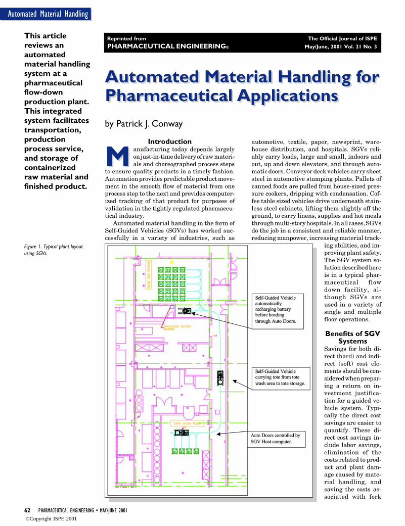
62 PHARMACEUTICAL ENGINEERING • MAY/JUNE 2001
Automated Material Handling
Automated Material Handling forPharmaceutical ApplicationsAutomated Material Handling forPharmaceutical Applications
Mby Patrick J. Conway
This articlereviews anautomatedmaterial handlingsystem at apharmaceuticalflow-downproduction plant.This integratedsystem facilitatestransportation,productionprocess service,and storage ofcontainerizedraw material andfinished product.
Introduction
M anufacturing today depends largelyon just-in-time delivery of raw materi-als and choreographed process steps
to ensure quality products in a timely fashion.Automation provides predictable product move-ment in the smooth flow of material from oneprocess step to the next and provides computer-ized tracking of that product for purposes ofvalidation in the tightly regulated pharmaceu-tical industry.
Automated material handling in the form ofSelf-Guided Vehicles (SGVs) has worked suc-cessfully in a variety of industries, such as
automotive, textile, paper, newsprint, ware-house distribution, and hospitals. SGVs reli-ably carry loads, large and small, indoors andout, up and down elevators, and through auto-matic doors. Conveyor deck vehicles carry sheetsteel in automotive stamping plants. Pallets ofcanned foods are pulled from house-sized pres-sure cookers, dripping with condensation. Cof-fee table sized vehicles drive underneath stain-less steel cabinets, lifting them slightly off theground, to carry linens, supplies and hot mealsthrough multi-story hospitals. In all cases, SGVsdo the job in a consistent and reliable manner,reducing manpower, increasing material track-
ing abilities, and im-proving plant safety.The SGV system so-lution described hereis in a typical phar-maceutical flowdown facility, al-though SGVs areused in a variety ofsingle and multiplefloor operations.
Benefits of SGVSystems
Savings for both di-rect (hard) and indi-rect (soft) cost ele-ments should be con-sidered when prepar-ing a return on in-vestment justifica-tion for a guided ve-hicle system. Typi-cally the direct costsavings are easier toquantify. These di-rect cost savings in-clude labor savings,elimination of thecosts related to prod-uct and plant dam-age caused by mate-rial handling, andsaving the costs as-sociated with fork
Figure 1. Typical plant layoutusing SGVs.
Reprinted from The Official Journal of ISPE
PHARMACEUTICAL ENGINEERING® May/June, 2001 Vol. 21 No. 3
©Copyright ISPE 2001
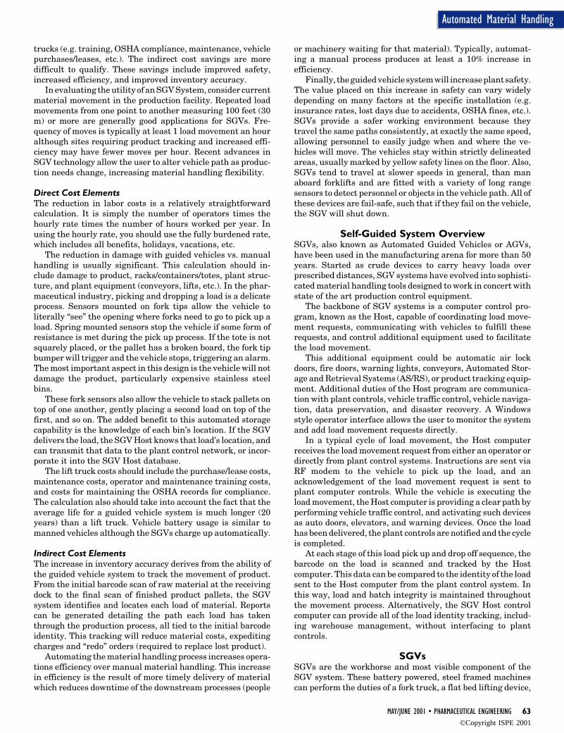
MAY/JUNE 2001 • PHARMACEUTICAL ENGINEERING 63
Automated Material Handling
trucks (e.g. training, OSHA compliance, maintenance, vehiclepurchases/leases, etc.). The indirect cost savings are moredifficult to qualify. These savings include improved safety,increased efficiency, and improved inventory accuracy.
In evaluating the utility of an SGV System, consider currentmaterial movement in the production facility. Repeated loadmovements from one point to another measuring 100 feet (30m) or more are generally good applications for SGVs. Fre-quency of moves is typically at least 1 load movement an houralthough sites requiring product tracking and increased effi-ciency may have fewer moves per hour. Recent advances inSGV technology allow the user to alter vehicle path as produc-tion needs change, increasing material handling flexibility.
Direct Cost ElementsThe reduction in labor costs is a relatively straightforwardcalculation. It is simply the number of operators times thehourly rate times the number of hours worked per year. Inusing the hourly rate, you should use the fully burdened rate,which includes all benefits, holidays, vacations, etc.
The reduction in damage with guided vehicles vs. manualhandling is usually significant. This calculation should in-clude damage to product, racks/containers/totes, plant struc-ture, and plant equipment (conveyors, lifts, etc.). In the phar-maceutical industry, picking and dropping a load is a delicateprocess. Sensors mounted on fork tips allow the vehicle toliterally “see” the opening where forks need to go to pick up aload. Spring mounted sensors stop the vehicle if some form ofresistance is met during the pick up process. If the tote is notsquarely placed, or the pallet has a broken board, the fork tipbumper will trigger and the vehicle stops, triggering an alarm.The most important aspect in this design is the vehicle will notdamage the product, particularly expensive stainless steelbins.
These fork sensors also allow the vehicle to stack pallets ontop of one another, gently placing a second load on top of thefirst, and so on. The added benefit to this automated storagecapability is the knowledge of each bin’s location. If the SGVdelivers the load, the SGV Host knows that load’s location, andcan transmit that data to the plant control network, or incor-porate it into the SGV Host database.
The lift truck costs should include the purchase/lease costs,maintenance costs, operator and maintenance training costs,and costs for maintaining the OSHA records for compliance.The calculation also should take into account the fact that theaverage life for a guided vehicle system is much longer (20years) than a lift truck. Vehicle battery usage is similar tomanned vehicles although the SGVs charge up automatically.
Indirect Cost ElementsThe increase in inventory accuracy derives from the ability ofthe guided vehicle system to track the movement of product.From the initial barcode scan of raw material at the receivingdock to the final scan of finished product pallets, the SGVsystem identifies and locates each load of material. Reportscan be generated detailing the path each load has takenthrough the production process, all tied to the initial barcodeidentity. This tracking will reduce material costs, expeditingcharges and “redo” orders (required to replace lost product).
Automating the material handling process increases opera-tions efficiency over manual material handling. This increasein efficiency is the result of more timely delivery of materialwhich reduces downtime of the downstream processes (people
or machinery waiting for that material). Typically, automat-ing a manual process produces at least a 10% increase inefficiency.
Finally, the guided vehicle system will increase plant safety.The value placed on this increase in safety can vary widelydepending on many factors at the specific installation (e.g.insurance rates, lost days due to accidents, OSHA fines, etc.).SGVs provide a safer working environment because theytravel the same paths consistently, at exactly the same speed,allowing personnel to easily judge when and where the ve-hicles will move. The vehicles stay within strictly delineatedareas, usually marked by yellow safety lines on the floor. Also,SGVs tend to travel at slower speeds in general, than manaboard forklifts and are fitted with a variety of long rangesensors to detect personnel or objects in the vehicle path. All ofthese devices are fail-safe, such that if they fail on the vehicle,the SGV will shut down.
Self-Guided System OverviewSGVs, also known as Automated Guided Vehicles or AGVs,have been used in the manufacturing arena for more than 50years. Started as crude devices to carry heavy loads overprescribed distances, SGV systems have evolved into sophisti-cated material handling tools designed to work in concert withstate of the art production control equipment.
The backbone of SGV systems is a computer control pro-gram, known as the Host, capable of coordinating load move-ment requests, communicating with vehicles to fulfill theserequests, and control additional equipment used to facilitatethe load movement.
This additional equipment could be automatic air lockdoors, fire doors, warning lights, conveyors, Automated Stor-age and Retrieval Systems (AS/RS), or product tracking equip-ment. Additional duties of the Host program are communica-tion with plant controls, vehicle traffic control, vehicle naviga-tion, data preservation, and disaster recovery. A Windowsstyle operator interface allows the user to monitor the systemand add load movement requests directly.
In a typical cycle of load movement, the Host computerreceives the load movement request from either an operator ordirectly from plant control systems. Instructions are sent viaRF modem to the vehicle to pick up the load, and anacknowledgement of the load movement request is sent toplant computer controls. While the vehicle is executing theload movement, the Host computer is providing a clear path byperforming vehicle traffic control, and activating such devicesas auto doors, elevators, and warning devices. Once the loadhas been delivered, the plant controls are notified and the cycleis completed.
At each stage of this load pick up and drop off sequence, thebarcode on the load is scanned and tracked by the Hostcomputer. This data can be compared to the identity of the loadsent to the Host computer from the plant control system. Inthis way, load and batch integrity is maintained throughoutthe movement process. Alternatively, the SGV Host controlcomputer can provide all of the load identity tracking, includ-ing warehouse management, without interfacing to plantcontrols.
SGVsSGVs are the workhorse and most visible component of theSGV system. These battery powered, steel framed machinescan perform the duties of a fork truck, a flat bed lifting device,
©Copyright ISPE 2001
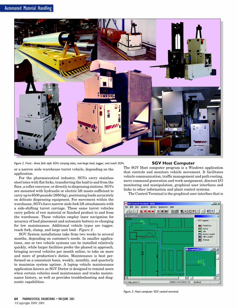
64 PHARMACEUTICAL ENGINEERING • MAY/JUNE 2001
Automated Material Handling
or a narrow aisle warehouse turret vehicle, depending on theapplication.
For the pharmaceutical industry, SGVs carry stainlesssteel totes with flat forks, transferring the load to and from thefloor, a roller conveyor, or directly to dispensing stations. SGVsare mounted with hydraulic or electric lift masts sufficient tocarry up to 6500 pounds (2950 kg), positioning loads accuratelyon delicate dispensing equipment. For movement within thewarehouse, SGVs have narrow aisle fork lift attachments witha side-shifting turret carriage. These same turret vehiclescarry pallets of raw material or finished product to and fromthe warehouse. These vehicles employ laser navigation foraccuracy of load placement and automatic battery re-chargingfor low maintenance. Additional vehicle types are tugger,reach fork, clamp, and large unit load - Figure 2.
SGV System installations take from two weeks to severalmonths, depending on customer’s needs. In smaller applica-tions, one or two vehicle systems can be installed relativelyquickly, while larger facilities prefer the phased in approach,bringing several vehicles per month online, to take on moreand more of production’s duties. Maintenance is best per-formed on a consistent basis, weekly, monthly, and quarterlyto maximize system uptime. A laptop vehicle maintenanceapplication known as SGV Doctor is designed to remind userswhen certain vehicles need maintenance and tracks mainte-nance history, as well as provides troubleshooting and diag-nostic capabilities.
SGV Host ComputerThe SGV Host computer program is a Windows applicationthat controls and monitors vehicle movement. It facilitatesvehicle communication, traffic management and path routing,move command generation and work assignment, discreet I/Omonitoring and manipulation, graphical user interfaces andlinks to other information and plant control systems.
The Control Terminal is the graphical user interface that is
Figure 2. Front - three fork style SGVs carrying totes, rear-large load, tugger, and reach SGVs.
Figure 3. Host computer SGV control terminal.
©Copyright ISPE 2001
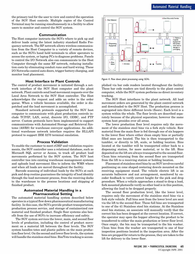
MAY/JUNE 2001 • PHARMACEUTICAL ENGINEERING 65
Automated Material Handling
the primary tool for the user to view and control the operationof the SGV Host controls. Multiple copies of the ControlTerminal may be running simultaneously in a facility to allowusers to monitor and control the SGV system.
CommunicationThe Host computer instructs the SGVs where to pick up anddeliver loads using the latest industry standard Radio Fre-quency network. The RF network allows wireless communica-tion from the Host Computer to a variety of remote devices,such as the SGVs hand held terminals to allow operators toaccess the system, or laptop PCs to diagnose problems. Panelsto control the I/O Network also can communicate to the HostComputer through the same RF network, reducing installa-tion costs by eliminating conduit runs and hard wiring. TheseI/O Networks control auto doors, trigger battery charging, andmonitor load placement.
Host Interface to Plant ControlsThe control of product movement is initiated through a net-work interface of the SGV Host computer and the plantnetwork. Plant controls send load movement requests over theLocal Area Network to the SGV Host controller. The Hostacknowledges the request and adds an order to the orderqueue. When a vehicle becomes available, the order is dis-patched and the load movement is accomplished.
Standard network protocols supported by the SGV hostcomputer to communicate with plant production controls in-clude TCP/IP, LAN, serial, discrete I/O, ODBC, and FTPserver. Custom protocols have been implemented to supportcommunications with Automated Storage and Retrieval Sys-tems (AS/RS) for warehouse conveyor applications. An addi-tional warehouse network interface requires the HLLAPIprotocol to support IBM 3270 terminal emulation.
Process ValidationTo enable the customer to meet cGMP and validation require-ments, the SGV controller uses a relational database, such asMicrosoft SQL server or Access, to track all product loadmovements performed by the SGV system. The SGV hostcontroller ties into existing warehouse management systemsand uploads load movement files to inform the WMS whereand when all loads are moved throughout the facility.
Barcode scanning of individual loads by the SGVs at eachpick and drop routine guarantees the integrity of load identitythrough the load movement process, from the receiving docksto the warehouse to the process locations and shipping offinished product.
Automated Material Handling in aPharmaceutical Setting
The automated material handling system described belowoperates in a typical flow down pharmaceutical manufacturingfacility. In this case, the SGVs provide product transportation,production process service, and storage of containerized rawmaterial and finished product. Single floor systems also ben-efit from the use of SGVs to increase efficiency and safety.
The SGV system services the lower, main, and second floorlevels of production, including the control of product move-ment on a material lift between the floor levels. The SGVsystem handles totes and plastic pallets on the main produc-tion floor level. On the second and lower floor levels, the systemwill handle the stainless steel bins. Bin/Tote tracking is accom-
plished via bar code readers located throughout the facility.These bar code readers are tied directly to the plant controlcomputer, while the SGV system performs no direct inventorytracking.
The SGV Host interfaces to the plant network. All loadmovement orders are generated by the plant control networkand downloaded to the SGV Host. The production process issegregated into three different levels (floors). Each level is asystem within the whole. The floor levels are described sepa-rately because of the physical separation; however the samesystem host presides over all areas.
The lower production floor level requires only the move-ment of the stainless steel bins via a fork style vehicle. Rawmaterial from the main floor is fed through one of six hoppersto the lower floor where either clean empty bins or partiallyfilled ones are located. The bin is then transported to thetumbler, or directly to lift, scale, or holding location. Binslocated at the tumbler will be transported either back to adispensing station, for more material, or to the lift. Binsdeposited on the lift are always transported to the second floor.Clean bins returning from the second floor are transportedfrom the lift to a receiving station or holding location.
Placement of stainless steel bins by an SGV involves carefulpositioning on cone shaped centering dowels mounted on thereceiving equipment stand. The vehicle electric lift is anaccurate ballscrew and nut arrangement, monitored by en-coder feedback to verify correct height for the pick and dropprocedure. When a vehicle approaches a stand to drop a load,fork mounted photocells verify no other load is in this position,allowing the load to be dropped properly.
The second floor production level, like the lower level,requires only the movement of the stainless steel bins via afork style vehicle. Full bins sent from the lower level are sentvia the lift to the second floor. These full bins are transportedto one of the 41 Stainless steel bin stations. At the Stainlesssteel bin stations, an associate will manually verify that thecorrect bin has been dropped at the correct location. If correct,the operator may open the hopper allowing the product to betransferred to either the main production or lower floor level.Once empty, the bin may be transported to the bin washer.Clean bins from the washer are transported to one of fourinspection positions located in the inspection area. After thebins are prepped for return to the process, they are taken to thelift for delivery to the lower floor.
Figure 4. Flow down plant processing using SGVs.
©Copyright ISPE 2001
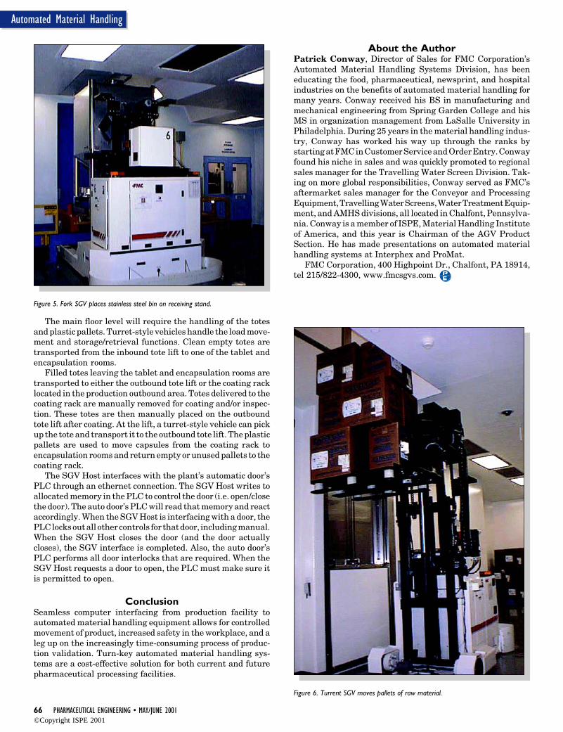
66 PHARMACEUTICAL ENGINEERING • MAY/JUNE 2001
Automated Material Handling
Figure 5. Fork SGV places stainless steel bin on receiving stand.
Figure 6. Turrent SGV moves pallets of raw material.
The main floor level will require the handling of the totesand plastic pallets. Turret-style vehicles handle the load move-ment and storage/retrieval functions. Clean empty totes aretransported from the inbound tote lift to one of the tablet andencapsulation rooms.
Filled totes leaving the tablet and encapsulation rooms aretransported to either the outbound tote lift or the coating racklocated in the production outbound area. Totes delivered to thecoating rack are manually removed for coating and/or inspec-tion. These totes are then manually placed on the outboundtote lift after coating. At the lift, a turret-style vehicle can pickup the tote and transport it to the outbound tote lift. The plasticpallets are used to move capsules from the coating rack toencapsulation rooms and return empty or unused pallets to thecoating rack.
The SGV Host interfaces with the plant’s automatic door’sPLC through an ethernet connection. The SGV Host writes toallocated memory in the PLC to control the door (i.e. open/closethe door). The auto door’s PLC will read that memory and reactaccordingly. When the SGV Host is interfacing with a door, thePLC locks out all other controls for that door, including manual.When the SGV Host closes the door (and the door actuallycloses), the SGV interface is completed. Also, the auto door’sPLC performs all door interlocks that are required. When theSGV Host requests a door to open, the PLC must make sure itis permitted to open.
ConclusionSeamless computer interfacing from production facility toautomated material handling equipment allows for controlledmovement of product, increased safety in the workplace, and aleg up on the increasingly time-consuming process of produc-tion validation. Turn-key automated material handling sys-tems are a cost-effective solution for both current and futurepharmaceutical processing facilities.
About the AuthorPatrick Conway, Director of Sales for FMC Corporation’sAutomated Material Handling Systems Division, has beeneducating the food, pharmaceutical, newsprint, and hospitalindustries on the benefits of automated material handling formany years. Conway received his BS in manufacturing andmechanical engineering from Spring Garden College and hisMS in organization management from LaSalle University inPhiladelphia. During 25 years in the material handling indus-try, Conway has worked his way up through the ranks bystarting at FMC in Customer Service and Order Entry. Conwayfound his niche in sales and was quickly promoted to regionalsales manager for the Travelling Water Screen Division. Tak-ing on more global responsibilities, Conway served as FMC’saftermarket sales manager for the Conveyor and ProcessingEquipment, Travelling Water Screens, Water Treatment Equip-ment, and AMHS divisions, all located in Chalfont, Pennsylva-nia. Conway is a member of ISPE, Material Handling Instituteof America, and this year is Chairman of the AGV ProductSection. He has made presentations on automated materialhandling systems at Interphex and ProMat.
FMC Corporation, 400 Highpoint Dr., Chalfont, PA 18914,tel 215/822-4300, www.fmcsgvs.com.
©Copyright ISPE 2001
8 PHARMACEUTICAL ENGINEERING • MAY/JUNE 2001
Flexible Batch Automation
Flexible Batch Automation andReporting Software Designs forActive PharmaceuticalIngredients (APIs) Manufacturing
Flexible Batch Automation andReporting Software Designs forActive PharmaceuticalIngredients (APIs) Manufacturing
M
by Bob Carrier
This articledescribes a cost-effectiveapproach toflexible batchprocesscomputerizedcontrol and datareportingappropriate forimplementationin a GMPcompliant multi-process, multi-product APImanufacturingfacility. Introduction
M ulti-process, multi-product API batchmanufacturing operations requirehighly flexible configurations of equip-
ment, procedures, and automation technology.Often a single product occupies a plant area forthree or fewer batches, after which the equip-ment is cleaned, then reconfigured for the nextproduct. It is typical for a single product to berun only once per year, and sometimes onceduring the facility lifetime.
A fully developed batch sequence automa-tion system provides functionality at the plantarea level for batch scheduling, equipment re-source allocation, inter-unit coordination, andmaterial history tracking. These software capa-bilities are expensive to develop and time-con-suming to validate, which leaves full batchsequence control best suited to dedicated manu-facturing facilities. In the case of a single plantarea used to produce many different drug com-pounds using different configurations of thesame equipment with short turnaround periodsbetween processes, it is impractical and costprohibitive to implement full batch sequencecontrol. However, there are some batch opera-tions that can be conducted automatically andthat are common to many API processes. Theseoperations are candidates for batch sequenceautomation in that they are reusable indepen-dent of equipment scale, plus the related valida-tion documentation package and qualificationtest procedures are reused in the same way.
This article is based on engineering experi-ence gained during the 1998-2000 grassrootsdesign and construction of a $125 million APIManufacturing Plant near Tainan, Taiwan. Thedrug compounds from this plant are manufac-tured in compliance with GMP regulations asrequired for drug sale in the US. This APIfacility is composed of different plant areas,each arranged in individual suites ranging inscale from kilo lab to pilot plant and up to large
scale manufacturing. This plant was automatedwith a Fisher-Rosemount Systems Inc. DeltaV™ DCS configured with the batch control suiteof software, which was developed and validatedin accordance with guidance published in theGAMP Guide 3.0.1 For the pilot plant and manu-facturing scale equipment, the manual activi-ties that would most often be conducted by anoperator during batch processing were selectedfor automation. These operations are reactorbulk temperature ramping, vessel nitrogen purg-ing, vessel controlled rate depressurization,hydrogen reactor explosive vapor vent and dilu-tion control, controlled rate chemical reactantfeed based on reactor temperature requirements,single fluid heat transfer system managementand, most commonly, reactor jacket utility se-lection and manifold valve positioning. Someadditional batch sequence control software wasdeveloped for the kilo lab as required to accom-modate specialized glassware configurations,custom heat transfer systems and process op-erations unique to that plant area.
Batch control software for the example APIfacility resides at the operation and phase levelof the model detailed in the ISA S88.01 stan-dard.2 In this model, phases form the softwarebuilding blocks which can be assembled in end-less combinations to automate selected batchoperations on each process unit. Phase logic isthe workhorse of batch automation at the pro-cess unit level, and when well designed, pro-vides great utility and flexibility.
Substantial benefits are available from au-tomation of batch operations that are reusablefor many products, and that are independent ofoperational scale. Benefits include the ability toquickly adapt proven controls as the productschedule changes, repeatability of complex op-erations within a product campaign, and reduc-tion in production errors related to use of thecontrol system. The long-range benefit of thisapproach is that for products transferred to
Reprinted from The Official Journal of ISPE
PHARMACEUTICAL ENGINEERING® May/June, 2001 Vol. 21 No. 3
©Copyright ISPE 2001
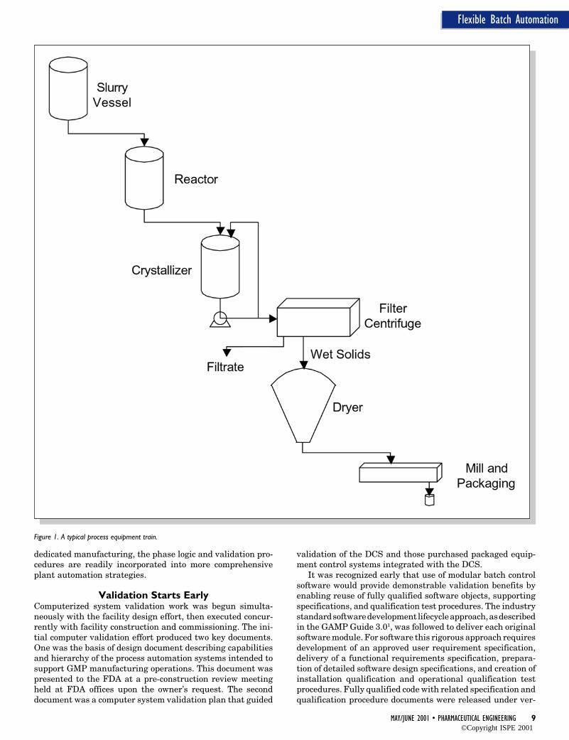
MAY/JUNE 2001 • PHARMACEUTICAL ENGINEERING 9
Flexible Batch Automation
dedicated manufacturing, the phase logic and validation pro-cedures are readily incorporated into more comprehensiveplant automation strategies.
Validation Starts EarlyComputerized system validation work was begun simulta-neously with the facility design effort, then executed concur-rently with facility construction and commissioning. The ini-tial computer validation effort produced two key documents.One was the basis of design document describing capabilitiesand hierarchy of the process automation systems intended tosupport GMP manufacturing operations. This document waspresented to the FDA at a pre-construction review meetingheld at FDA offices upon the owner’s request. The seconddocument was a computer system validation plan that guided
validation of the DCS and those purchased packaged equip-ment control systems integrated with the DCS.
It was recognized early that use of modular batch controlsoftware would provide demonstrable validation benefits byenabling reuse of fully qualified software objects, supportingspecifications, and qualification test procedures. The industrystandard software development lifecycle approach, as describedin the GAMP Guide 3.01, was followed to deliver each originalsoftware module. For software this rigorous approach requiresdevelopment of an approved user requirement specification,delivery of a functional requirements specification, prepara-tion of detailed software design specifications, and creation ofinstallation qualification and operational qualification testprocedures. Fully qualified code with related specification andqualification procedure documents were released under ver-
Figure 1. A typical process equipment train.
©Copyright ISPE 2001
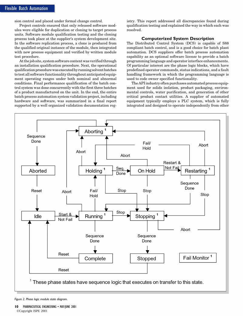
10 PHARMACEUTICAL ENGINEERING • MAY/JUNE 2001
Flexible Batch Automation
Figure 2. Phase logic module state diagram.
sion control and placed under formal change control.Project controls ensured that only released software mod-
ules were eligible for duplication or cloning to target processunits. Software module qualification testing and the cloningprocess took place at the supplier’s system development site.In the software replication process, a clone is produced fromthe qualified original instance of the module, then integratedwith new process equipment and verified by written moduletest procedure.
At the job site, system software content was verified throughan installation qualification procedure. Next, the operationalqualification procedure was executed by running solvent batchesto test all software functionality throughout anticipated equip-ment operating ranges under both nominal and abnormalconditions. Final performance qualification of the batch con-trol system was done concurrently with the first three batchesof a product manufactured on the unit. In the end, the entirebatch process automation system validation project, includinghardware and software, was summarized in a final reportsupported by a well organized validation documentation reg-
istry. This report addressed all discrepancies found duringqualification testing and explained the way in which each wasresolved.
Computerized System DescriptionThe Distributed Control System (DCS) is capable of S88compliant batch control, and is a good choice for batch plantautomation. DCS suppliers offer batch process automationcapability as an optional software license to provide a batchprogramming language and operator interface enhancements.Of particular interest are the phase logic blocks, which havepredefined operator commands, status indications, and a faulthandling framework in which the programming language isused to code owner specified functionality.
The API industry often purchases automated process equip-ment used for solids isolation, product packaging, environ-mental controls, water purification, and generation of othercritical product contact utilities. A supplier of automatedequipment typically employs a PLC system, which is fullyintegrated and designed to operate independently from other
©Copyright ISPE 2001
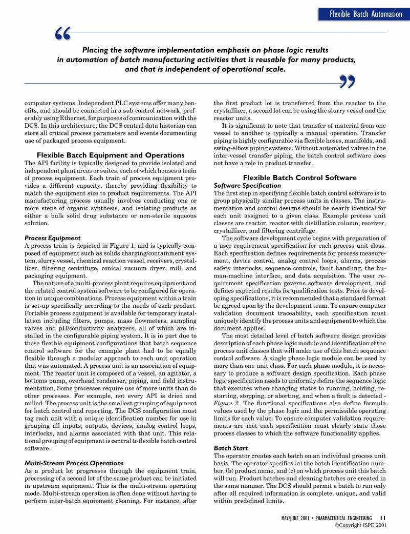
MAY/JUNE 2001 • PHARMACEUTICAL ENGINEERING 11
Flexible Batch Automation
computer systems. Independent PLC systems offer many ben-efits, and should be connected in a sub-control network, pref-erably using Ethernet, for purposes of communication with theDCS. In this architecture, the DCS central data historian canstore all critical process parameters and events documentinguse of packaged process equipment.
Flexible Batch Equipment and OperationsThe API facility is typically designed to provide isolated andindependent plant areas or suites, each of which houses a trainof process equipment. Each train of process equipment pro-vides a different capacity, thereby providing flexibility tomatch the equipment size to product requirements. The APImanufacturing process usually involves conducting one ormore steps of organic synthesis, and isolating products aseither a bulk solid drug substance or non-sterile aqueoussolution.
Process EquipmentA process train is depicted in Figure 1, and is typically com-posed of equipment such as solids charging/containment sys-tem, slurry vessel, chemical reaction vessel, receivers, crystal-lizer, filtering centrifuge, conical vacuum dryer, mill, andpackaging equipment.
The nature of a multi-process plant requires equipment andthe related control system software to be configured for opera-tion in unique combinations. Process equipment within a trainis set-up specifically according to the needs of each product.Portable process equipment is available for temporary instal-lation including filters, pumps, mass flowmeters, samplingvalves and pH/conductivity analyzers, all of which are in-stalled in the configurable piping system. It is in part due tothese flexible equipment configurations that batch sequencecontrol software for the example plant had to be equallyflexible through a modular approach to each unit operationthat was automated. A process unit is an association of equip-ment. The reactor unit is composed of a vessel, an agitator, abottoms pump, overhead condenser, piping, and field instru-mentation. Some processes require use of more units than doother processes. For example, not every API is dried andmilled. The process unit is the smallest grouping of equipmentfor batch control and reporting. The DCS configuration musttag each unit with a unique identification number for use ingrouping all inputs, outputs, devices, analog control loops,interlocks, and alarms associated with that unit. This rela-tional grouping of equipment is central to flexible batch controlsoftware.
Multi-Stream Process OperationsAs a product lot progresses through the equipment train,processing of a second lot of the same product can be initiatedin upstream equipment. This is the multi-stream operatingmode. Multi-stream operation is often done without having toperform inter-batch equipment cleaning. For instance, after
the first product lot is transferred from the reactor to thecrystallizer, a second lot can be using the slurry vessel and thereactor units.
It is significant to note that transfer of material from onevessel to another is typically a manual operation. Transferpiping is highly configurable via flexible hoses, manifolds, andswing-elbow piping systems. Without automated valves in theinter-vessel transfer piping, the batch control software doesnot have a role in product transfer.
Flexible Batch Control SoftwareSoftware SpecificationThe first step in specifying flexible batch control software is togroup physically similar process units in classes. The instru-mentation and control designs should be nearly identical foreach unit assigned to a given class. Example process unitclasses are reactor, reactor with distillation column, receiver,crystallizer, and filtering centrifuge.
The software development cycle begins with preparation ofa user requirement specification for each process unit class.Each specification defines requirements for process measure-ment, device control, analog control loops, alarms, processsafety interlocks, sequence controls, fault handling, the hu-man-machine interface, and data acquisition. The user re-quirement specification governs software development, anddefines expected results for qualification tests. Prior to devel-oping specifications, it is recommended that a standard formatbe agreed upon by the development team. To ensure computervalidation document traceability, each specification mustuniquely identify the process units and equipment to which thedocument applies.
The most detailed level of batch software design providesdescription of each phase logic module and identification of theprocess unit classes that will make use of this batch sequencecontrol software. A single phase logic module can be used bymore than one unit class. For each phase module, it is neces-sary to produce a software design specification. Each phaselogic specification needs to uniformly define the sequence logicthat executes when changing states to running, holding, re-starting, stopping, or aborting, and when a fault is detected -Figure 2. The functional specifications also define formulavalues used by the phase logic and the permissible operatinglimits for each value. To ensure computer validation require-ments are met each specification must clearly state thoseprocess classes to which the software functionality applies.
Batch StartThe operator creates each batch on an individual process unitbasis. The operator specifies (a) the batch identification num-ber, (b) product name, and (c) on which process unit this batchwill run. Product batches and cleaning batches are created inthe same manner. The DCS should permit a batch to run onlyafter all required information is complete, unique, and validwithin predefined limits.
““ ““Placing the software implementation emphasis on phase logic results in automation of batch manufacturing activities that is reusable for many products,
and that is independent of operational scale.
©Copyright ISPE 2001
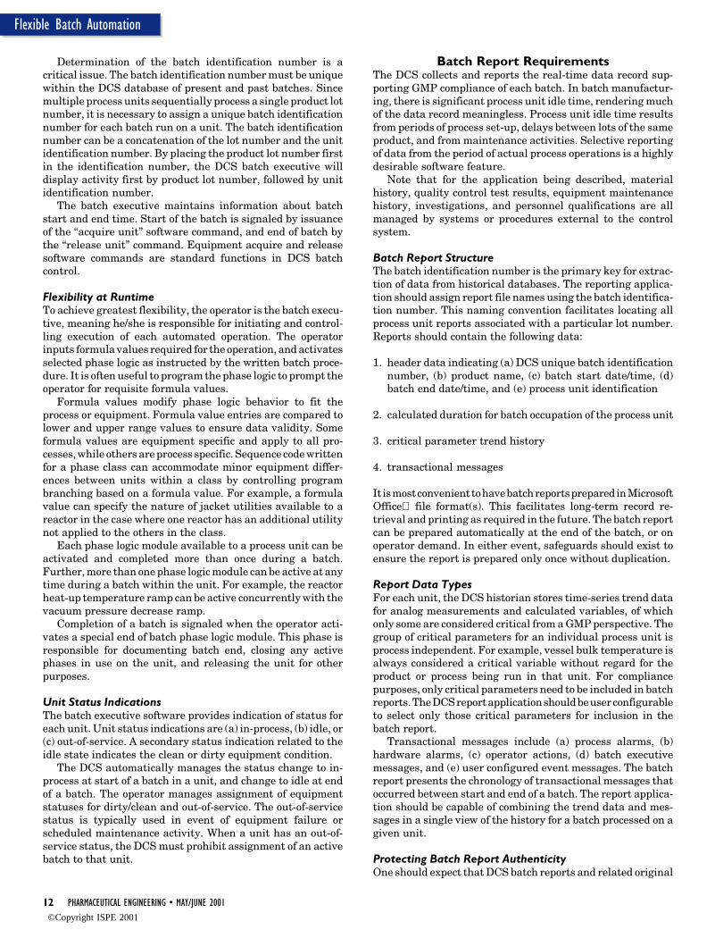
12 PHARMACEUTICAL ENGINEERING • MAY/JUNE 2001
Flexible Batch Automation
Determination of the batch identification number is acritical issue. The batch identification number must be uniquewithin the DCS database of present and past batches. Sincemultiple process units sequentially process a single product lotnumber, it is necessary to assign a unique batch identificationnumber for each batch run on a unit. The batch identificationnumber can be a concatenation of the lot number and the unitidentification number. By placing the product lot number firstin the identification number, the DCS batch executive willdisplay activity first by product lot number, followed by unitidentification number.
The batch executive maintains information about batchstart and end time. Start of the batch is signaled by issuanceof the “acquire unit” software command, and end of batch bythe “release unit” command. Equipment acquire and releasesoftware commands are standard functions in DCS batchcontrol.
Flexibility at RuntimeTo achieve greatest flexibility, the operator is the batch execu-tive, meaning he/she is responsible for initiating and control-ling execution of each automated operation. The operatorinputs formula values required for the operation, and activatesselected phase logic as instructed by the written batch proce-dure. It is often useful to program the phase logic to prompt theoperator for requisite formula values.
Formula values modify phase logic behavior to fit theprocess or equipment. Formula value entries are compared tolower and upper range values to ensure data validity. Someformula values are equipment specific and apply to all pro-cesses, while others are process specific. Sequence code writtenfor a phase class can accommodate minor equipment differ-ences between units within a class by controlling programbranching based on a formula value. For example, a formulavalue can specify the nature of jacket utilities available to areactor in the case where one reactor has an additional utilitynot applied to the others in the class.
Each phase logic module available to a process unit can beactivated and completed more than once during a batch.Further, more than one phase logic module can be active at anytime during a batch within the unit. For example, the reactorheat-up temperature ramp can be active concurrently with thevacuum pressure decrease ramp.
Completion of a batch is signaled when the operator acti-vates a special end of batch phase logic module. This phase isresponsible for documenting batch end, closing any activephases in use on the unit, and releasing the unit for otherpurposes.
Unit Status IndicationsThe batch executive software provides indication of status foreach unit. Unit status indications are (a) in-process, (b) idle, or(c) out-of-service. A secondary status indication related to theidle state indicates the clean or dirty equipment condition.
The DCS automatically manages the status change to in-process at start of a batch in a unit, and change to idle at endof a batch. The operator manages assignment of equipmentstatuses for dirty/clean and out-of-service. The out-of-servicestatus is typically used in event of equipment failure orscheduled maintenance activity. When a unit has an out-of-service status, the DCS must prohibit assignment of an activebatch to that unit.
Batch Report RequirementsThe DCS collects and reports the real-time data record sup-porting GMP compliance of each batch. In batch manufactur-ing, there is significant process unit idle time, rendering muchof the data record meaningless. Process unit idle time resultsfrom periods of process set-up, delays between lots of the sameproduct, and from maintenance activities. Selective reportingof data from the period of actual process operations is a highlydesirable software feature.
Note that for the application being described, materialhistory, quality control test results, equipment maintenancehistory, investigations, and personnel qualifications are allmanaged by systems or procedures external to the controlsystem.
Batch Report StructureThe batch identification number is the primary key for extrac-tion of data from historical databases. The reporting applica-tion should assign report file names using the batch identifica-tion number. This naming convention facilitates locating allprocess unit reports associated with a particular lot number.Reports should contain the following data:
1. header data indicating (a) DCS unique batch identificationnumber, (b) product name, (c) batch start date/time, (d)batch end date/time, and (e) process unit identification
2. calculated duration for batch occupation of the process unit
3. critical parameter trend history
4. transactional messages
It is most convenient to have batch reports prepared in MicrosoftOffice file format(s). This facilitates long-term record re-trieval and printing as required in the future. The batch reportcan be prepared automatically at the end of the batch, or onoperator demand. In either event, safeguards should exist toensure the report is prepared only once without duplication.
Report Data TypesFor each unit, the DCS historian stores time-series trend datafor analog measurements and calculated variables, of whichonly some are considered critical from a GMP perspective. Thegroup of critical parameters for an individual process unit isprocess independent. For example, vessel bulk temperature isalways considered a critical variable without regard for theproduct or process being run in that unit. For compliancepurposes, only critical parameters need to be included in batchreports. The DCS report application should be user configurableto select only those critical parameters for inclusion in thebatch report.
Transactional messages include (a) process alarms, (b)hardware alarms, (c) operator actions, (d) batch executivemessages, and (e) user configured event messages. The batchreport presents the chronology of transactional messages thatoccurred between start and end of a batch. The report applica-tion should be capable of combining the trend data and mes-sages in a single view of the history for a batch processed on agiven unit.
Protecting Batch Report AuthenticityOne should expect that DCS batch reports and related original
©Copyright ISPE 2001
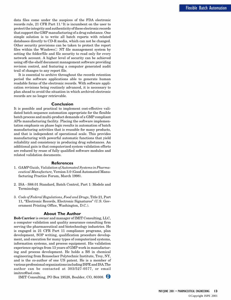
MAY/JUNE 2001 • PHARMACEUTICAL ENGINEERING 13
Flexible Batch Automation
data files come under the auspices of the FDA electronicrecords rule, 21 CFR Part 11.3 It is incumbent on the user toprotect the integrity and authenticity of these electronic recordsthat support the GMP manufacturing of a drug substance. Onesimple solution is to write all batch reports with relateddatabases directly to CD-R media, which can not be changed.Other security provisions can be taken to protect the reportfiles within the Windows NT file management system bysetting the folder/file and file security to read only for everynetwork account. A higher level of security can be achievedusing off-the-shelf document management software providingrevision control, and featuring a computer generated audittrail of changes to any report file.
It is essential to archive throughout the records retentionperiod the software applications able to generate humanreadable forms of the electronic records. With software appli-cation revisions being routinely advanced, it is necessary toplan ahead to avoid the situation in which archived electronicrecords are no longer retrievable.
ConclusionIt is possible and practical to implement cost-effective vali-dated batch sequence automation appropriate for the flexiblebatch process and multi-product demands of a GMP compliantAPIs manufacturing facility. Placing the software implemen-tation emphasis on phase logic results in automation of batchmanufacturing activities that is reusable for many products,and that is independent of operational scale. This providesmanufacturing with powerful automatic functions that yieldreliability and consistency in producing drug substances. Anadditional gain is that computerized system validation effortsare reduced by reuse of fully qualified software modules andrelated validation documents.
References1. GAMP Guide, Validation of Automated Systems in Pharma-
ceutical Manufacture, Version 3.0 (Good Automated Manu-facturing Practice Forum, March 1998).
2. ISA - S88.01 Standard, Batch Control, Part 1: Models andTerminology.
3. Code of Federal Regulations, Food and Drugs, Title 21, Part11, “Electronic Records, Electronic Signatures” (U.S. Gov-ernment Printing Office, Washington, D.C.).
About The AuthorBob Carrier is owner and manager of IMIT Consulting, LLC,a computer validation and quality assurance consulting firmserving the pharmaceutical and biotechnology industries. Heis engaged in 21 CFR Part 11 compliance programs, plandevelopment, SOP writing, qualification procedure develop-ment, and execution for many types of computerized systems,information systems, and process equipment. His validationexperience springs from 13 years of GMP work in manufactur-ing and process development. He holds a BS in chemicalengineering from Rensselaer Polytechnic Institute, Troy, NY,and is the co-author of one US patent. He is a member ofvarious professional organizations including ISPE and ISA.Theauthor can be contacted at 303/527-0577, or [email protected].
IMIT Consulting, PO Box 19528, Boulder, CO, 80308.
©Copyright ISPE 2001
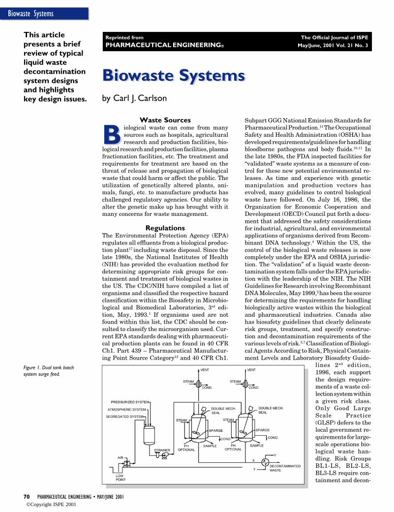
70 PHARMACEUTICAL ENGINEERING • MAY/JUNE 2001
Biowaste Systems
Figure 1. Dual tank batchsystem surge feed.
Biowaste SystemsBiowaste Systems
B
by Carl J. Carlson
This articlepresents a briefreview of typicalliquid wastedecontaminationsystem designsand highlightskey design issues.
Waste Sources
B iological waste can come from manysources such as hospitals, agriculturalresearch and production facilities, bio-
logical research and production facilities, plasmafractionation facilities, etc. The treatment andrequirements for treatment are based on thethreat of release and propagation of biologicalwaste that could harm or affect the public. Theutilization of genetically altered plants, ani-mals, fungi, etc. to manufacture products haschallenged regulatory agencies. Our ability toalter the genetic make up has brought with itmany concerns for waste management.
RegulationsThe Environmental Protection Agency (EPA)regulates all effluents from a biological produc-tion plant17 including waste disposal. Since thelate 1980s, the National Institutes of Health(NIH) has provided the evaluation method fordetermining appropriate risk groups for con-tainment and treatment of biological wastes inthe US. The CDC/NIH have compiled a list oforganisms and classified the respective hazardclassification within the Biosafety in Microbio-logical and Biomedical Laboratories, 3rd edi-tion, May, 1993.1 If organisms used are notfound within this list, the CDC should be con-sulted to classify the microorganism used. Cur-rent EPA standards dealing with pharmaceuti-cal production plants can be found in 40 CFRCh1. Part 439 – Pharmaceutical Manufactur-ing Point Source Category12 and 40 CFR Ch1.
Subpart GGG National Emission Standards forPharmaceutical Production.14 The OccupationalSafety and Health Administration (OSHA) hasdeveloped requirements/guidelines for handlingbloodborne pathogens and body fluids.10,11 Inthe late 1980s, the FDA inspected facilities for“validated” waste systems as a measure of con-trol for these new potential environmental re-leases. As time and experience with geneticmanipulation and production vectors hasevolved, many guidelines to control biologicalwaste have followed. On July 16, 1986, theOrganization for Economic Cooperation andDevelopment (OECD) Council put forth a docu-ment that addressed the safety considerationsfor industrial, agricultural, and environmentalapplications of organisms derived from Recom-binant DNA technology.4 Within the US, thecontrol of the biological waste releases is nowcompletely under the EPA and OSHA jurisdic-tion. The “validation” of a liquid waste decon-tamination system falls under the EPA jurisdic-tion with the leadership of the NIH. The NIHGuidelines for Research involving RecombinantDNA Molecules, May 1999,2 has been the sourcefor determining the requirements for handlingbiologically active wastes within the biologicaland pharmaceutical industries. Canada alsohas biosafety guidelines that clearly delineaterisk groups, treatment, and specify construc-tion and decontamination requirements of thevarious levels of risk.5,7 Classification of Biologi-cal Agents According to Risk, Physical Contain-ment Levels and Laboratory Biosafety Guide-
lines 2nd edition,1996, each supportthe design require-ments of a waste col-lection system withina given risk class.Only Good LargeScale Practice(GLSP) defers to thelocal government re-quirements for large-scale operations bio-logical waste han-dling. Risk GroupsBL1-LS, BL2-LS,BL3-LS require con-tainment and decon-
Reprinted from The Official Journal of ISPE
PHARMACEUTICAL ENGINEERING® May/June, 2001 Vol. 21 No. 3
©Copyright ISPE 2001

MAY/JUNE 2001 • PHARMACEUTICAL ENGINEERING 71
Biowaste Systems
tamination prior to release and BL4-LS require waste collec-tion and decontamination adjacent to the containmentarea.1,2,3,8,9
Biowaste Modes of DecontaminationThe method of waste collection and subsequent decontamina-tion will vary based on the form of the waste (solid, liquid,solid-liquid) and the volume processed. A lab autoclave is thesimplest form of biowaste system that employs manual meansof collection and disposal of the solid or liquid waste. This ispractical for small volumes of waste. The decontaminationprocess is usually automated and documented via autoclavecontroller to assure reproducibility of the decontaminationprocess. Manual chemical decontamination is often employedin hospitals, universities, and laboratories. Large volumes ofmedical waste (more than 500,000 lbs/year) can be processedon site via a large, continuous feed autoclave sterilizationsystem.15 Large scale treatment of solid regulated medicalwaste, infectious waste, and clinical waste to a residue that isclassified as a municipal land fill waste is a practical andeconomical solution, and can be made in compliance with theEPA Clean Air Act standards.
Large volumes of liquid biological waste are generated fromplasma fractionation facilities, antibody production facilities,and any biological or drug production facilities utilizing micro-organisms to generate product. Most production facilities willfall under BSL1-LS for antibody production although organ-isms classified under BSL2-LS and very infrequently BSL3-LSalso are utilized for some vaccine or therapeutic peptideproduction. The NIH guidelines list a good portion of theorganisms used in order of their corresponding hazard classi-fication. The hazard classification is determined based on theorganism's potential threat to the environment and the poten-tial for survival after release. There is a small number oforganisms that are well characterized such as E. coli that havebeen exempt from the BL guidelines by the CDC. Theseorganisms can be handled utilizing GLSP precautions. If themicroorganism is not listed, an evaluation must be completedwith the CDC/NIH. The flexibility required of the developmentor clinical production facility is most reasonably handled by aBatch Liquid Waste Decontamination System (LWDS).Changes to system requirements (kill times or temperatures)are easily modified in the batch system. Large productionfacilities with a moderate or defined range of microorganismswill best be handled by a continuous system. One must becareful to meet the conditions set forth in the permitting cycled
Figure 2. Dual tank batch system no surge feed.
process for either continuous or batch release waste systems.Waste effluents shall be sampled consistent with the wastethroughput (continuous vs. batch) and EPA sampling require-ments as well as any local or state requirements.
Liquid Waste Decontamination System (LWDS)The following is a review of LWDSs utilized in the pharmaceu-tical industry today. These systems are employed to decon-taminate cell culture or microbial fermentation biologicallycontaminated waste streams utilizing an overkill approach(see validation). In addition to biological activity, the release ofhazardous material consisting of chemical or toxic nature alsomust be addressed. These limits are described as HazardousAir Pollutants (HAP) and Hazardous Chemicals as defined bythe EPA.14 Biological load reduction is treated (inactivated)within a Waste Management Unit (kill tank). The owner/operator shall monitor the Total Suspended Solids (TSS),Biological Oxygen Demand (BOD), and biomass concentra-tion.
Modes of System OperationThermal waste decontamination is accomplished in one oftwo ways. The most common method used to inactivate biologi-cal waste in small laboratories and pilot facilities is to rampthe reactor up to 121°C (250°F), hold for 20 to 30 minutes, thencool down to a maximum temperature of 60°C (140°F) prior torelease. If neutralization is not performed in the LWDS, thenwaste must be directed to the neutralization system prior todischarge. After cool down, the material can be disposed of inthe sanitary drain. Note that this process assumes that theproduct will be isolated from the cell mass prior to biologicalinactivation. If cell separation occurs within a pressurizedsystem like a cell rupture step, then care not to affect thebackpressure to the process must be provided when transfer-ring the waste to the LWDS. For larger clinical or productionfacilities, the waste comes from many operations and it be-comes practical to collect these wastes for automatic decon-tamination. The automated decontamination can occur in abatch mode or a continuous operation as described below.
Thermal batch decontamination is a straightforwardcollection, decontamination, cool down, and release operation.The collection can be accomplished via a surge feed where thesurge tank level is used to control the feed rate to the batch killtank – Figure 1. Dual kill tanks provide time for the killoperation to occur and will allow uninterrupted service in amulti-functional facility. The kill tank will be successfully
Figure 3. Single tank system continuous system.
©Copyright ISPE 2001
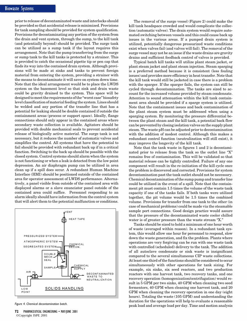
72 PHARMACEUTICAL ENGINEERING • MAY/JUNE 2001
Biowaste Systems
The removal of the surge vessel (Figure 2) could make thekill tank headspace crowded and would complicate the collec-tion (automatic valves). The drain system would require auto-mated switching between vessels and this could cause back upissues in the various areas. If a pumped drain system isutilized, potentially dangerous pressurized waste conditionsexist when valves fail (and valves will fail). The removal of thesurge vessel may not be an issue if the waste drains are gravitydrains and sufficient feedback control of valves is provided.
Typical batch kill tanks will utilize plant steam jacket, orplant steam jacket and plant steam injection. Steam spargingis a preferred method because it is consistent (less foulingissues) and provides more efficiency in heat transfer. Note thatthe kill tank would still be jacketed in case there is a problemwith the sparger. If the sparger fails, the system can still becycled through decontamination. The tanks are sized to ac-count for the increased volume provided by steam condensate.Attention to sound attenuation within the kill tank contain-ment area should be provided if a sparge system is utilized.Note that the containment issues and back contamination ofthe plant steam system must be addressed when using asparging system. By monitoring the pressure differential be-tween the plant steam and the kill tank, a potential back flowcan be prevented by closing isolation valves on the supply plantsteam. The waste pH can be adjusted prior to decontaminationwith the addition of modest control. Although this makes aredundant control function (neutralization will still exist), itmay improve the longevity of the kill tank.
Note that the tank waste in figures 1 and 2 is decontami-nated prior to release from the tank so the outlet line “X”remains free of contamination. This will be validated so thatmaterial release can be tightly controlled. Failure of any onecomponent will result in the re-initiation of the kill cycle oncethe problem is discovered and corrected. Provisions for systemdecontamination past the tank outlet should not be necessary.Chemical decontamination of the sump pump and transfer linecould be utilized in the event of a spill. Note that the contain-ment pit must contain 1.5 times the volume of the waste tankcapacity if one of the tanks fails. If both tanks were utilizedtogether, the pit volume would be 1.5 times the combinedvolume. Provisions for transfer from one tank to the other (incase of mechanical problems) could be made via the steamablesample port connections. Good design practice would assurethat the pressure of the decontaminated waste cooler chilledwater is of greater pressure than the waste stream “X.”
Tanks should be sized to hold a minimum of one hour worthof waste (averaged within reason). In a redundant tank sys-tem, this would allow one hour for personnel to respond, slowdown the waste generation, and fix the problem. Plants whereoperations are very forgiving can be run with one waste tankwith controlled (scheduled) delivery to the tank. The additionof all autoclave condensate or sink waste is insignificantcompared to the several simultaneous CIP waste collections.At least one third of the functions should be considered to occursimultaneously with other operations for tank sizing. Forexample, six sinks, six seed reactors, and two productionreactors with one harvest tank, two recovery tanks, and onerecovery operation (homogenization/centrifugation) would re-sult in 5 GPM per two sinks, 40 GPM when cleaning two seedfermentors, 40 GPM when cleaning one harvest tank, and 20GPM when cleaning the recovery operation in one day (eighthours). Totaling the waste (105 GPM) and understanding theduration for the operations will help to evaluate a reasonablepeak load and average load per day. Time and motion analysis
prior to release of decontaminated waste and interlocks shouldbe provided so that accidental release is minimized. Provisionsfor tank sampling should be provided for system qualification.Provisions for decontaminating any portion of the system fromthe drain and vent system, through the sump, to the kill tank(and potentially beyond) should be provided. The surge tankcan be utilized as a sump tank if the layout requires thisarrangement. Note that the pump transferring from the surgeor sump tank to the kill tanks is protected by a strainer. Thisis provided to catch the occasional pipette tip or pen cap thatfinds its way into the contained drain system. Although provi-sions will be made at sinks and tanks to prevent foreignmaterial from entering the system, providing a strainer withthe means to decontaminate it will save on system down time.Note that the ideal arrangement would be to place the LWDSsystem on the basement level so that sink and drain wastecould be gravity drained to the system. This space will bedesigned to meet the requirements of the “worst case” biosafetylevel classification of material feeding the system. Lines shouldbe welded and any portion of the transfer line that has apotential for leaking should be double contained if outside thecontainment areas (process or support space). Ideally, flangeconnections should only appear in the contained areas wheresecondary waste collection is available. Agitators should beprovided with double mechanical seals to prevent accidentalrelease of biologically active material. The surge tank is notnecessary, but it reduces the number of automatic valves andsimplifies the control. All systems that have the potential tofail should be provided with redundant back up if in a criticalfunction. Switching to the back up should be possible with theclosed system. Control systems should alarm when the systemis not functioning or when a leak is detected from the low pointdepression. An air diaphragm pump can be utilized in areaclean up if a spill does occur. A redundant Human MachineInterface (HMI) should be positioned outside of the containedarea for operator assessment of LWDS performance. Alterna-tively, a panel visible from outside of the contained area withdisplayed alarms or a slave enunciator panel outside of thecontained area could suffice. Personnel responding to analarm ideally should have information from the control systemthat will alert them to the potential malfunction or conditions.
Figure 4. Chemical decontamination batch.
©Copyright ISPE 2001
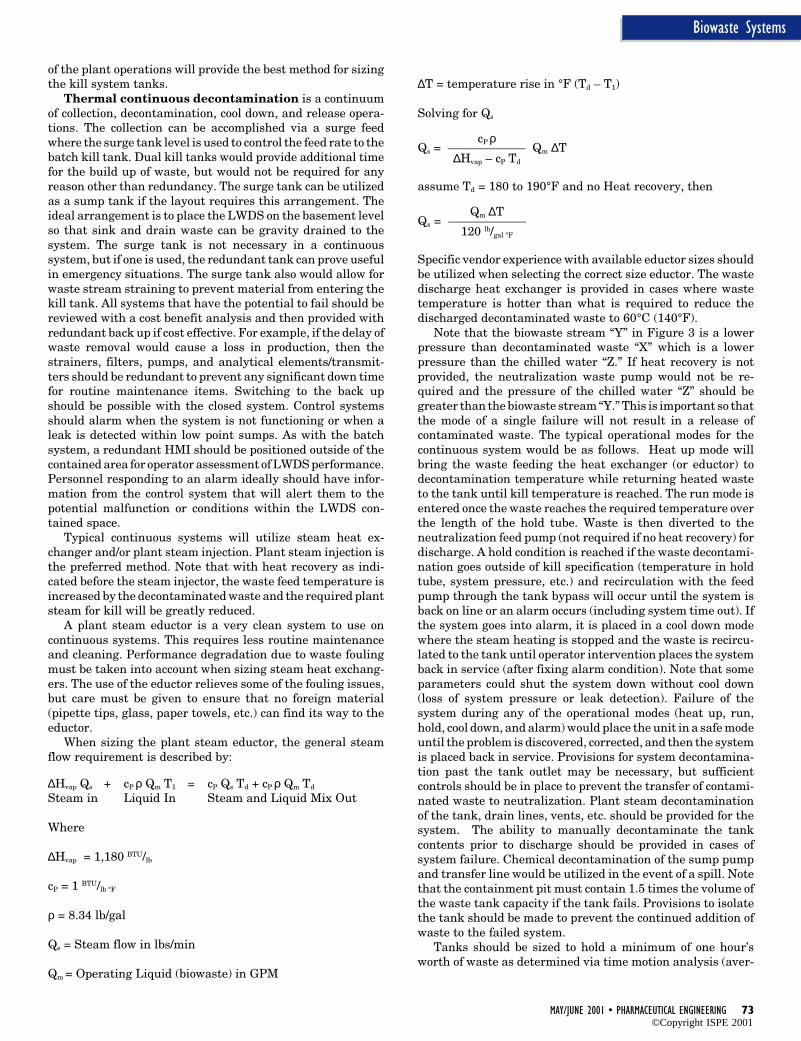
MAY/JUNE 2001 • PHARMACEUTICAL ENGINEERING 73
Biowaste Systems
of the plant operations will provide the best method for sizingthe kill system tanks.
Thermal continuous decontamination is a continuumof collection, decontamination, cool down, and release opera-tions. The collection can be accomplished via a surge feedwhere the surge tank level is used to control the feed rate to thebatch kill tank. Dual kill tanks would provide additional timefor the build up of waste, but would not be required for anyreason other than redundancy. The surge tank can be utilizedas a sump tank if the layout requires this arrangement. Theideal arrangement is to place the LWDS on the basement levelso that sink and drain waste can be gravity drained to thesystem. The surge tank is not necessary in a continuoussystem, but if one is used, the redundant tank can prove usefulin emergency situations. The surge tank also would allow forwaste stream straining to prevent material from entering thekill tank. All systems that have the potential to fail should bereviewed with a cost benefit analysis and then provided withredundant back up if cost effective. For example, if the delay ofwaste removal would cause a loss in production, then thestrainers, filters, pumps, and analytical elements/transmit-ters should be redundant to prevent any significant down timefor routine maintenance items. Switching to the back upshould be possible with the closed system. Control systemsshould alarm when the system is not functioning or when aleak is detected within low point sumps. As with the batchsystem, a redundant HMI should be positioned outside of thecontained area for operator assessment of LWDS performance.Personnel responding to an alarm ideally should have infor-mation from the control system that will alert them to thepotential malfunction or conditions within the LWDS con-tained space.
Typical continuous systems will utilize steam heat ex-changer and/or plant steam injection. Plant steam injection isthe preferred method. Note that with heat recovery as indi-cated before the steam injector, the waste feed temperature isincreased by the decontaminated waste and the required plantsteam for kill will be greatly reduced.
A plant steam eductor is a very clean system to use oncontinuous systems. This requires less routine maintenanceand cleaning. Performance degradation due to waste foulingmust be taken into account when sizing steam heat exchang-ers. The use of the eductor relieves some of the fouling issues,but care must be given to ensure that no foreign material(pipette tips, glass, paper towels, etc.) can find its way to theeductor.
When sizing the plant steam eductor, the general steamflow requirement is described by:
∆Hvap Qs + cP ρ Qm T1 = cP Qs Td + cP ρ Qm Td
Steam in Liquid In Steam and Liquid Mix Out
Where
∆Hvap = 1,180 BTU/lb
cP = 1 BTU/lb °F
ρ = 8.34 lb/gal
Qs = Steam flow in lbs/min
Qm = Operating Liquid (biowaste) in GPM
∆T = temperature rise in °F (Td – T1)
Solving for Qs
cP ρQs = _____________ Qm ∆T
∆Hvap – cP Td
assume Td = 180 to 190°F and no Heat recovery, then
Qm ∆TQs = _____________
120 lb/gal °F
Specific vendor experience with available eductor sizes shouldbe utilized when selecting the correct size eductor. The wastedischarge heat exchanger is provided in cases where wastetemperature is hotter than what is required to reduce thedischarged decontaminated waste to 60°C (140°F).
Note that the biowaste stream “Y” in Figure 3 is a lowerpressure than decontaminated waste “X” which is a lowerpressure than the chilled water “Z.” If heat recovery is notprovided, the neutralization waste pump would not be re-quired and the pressure of the chilled water “Z” should begreater than the biowaste stream “Y.” This is important so thatthe mode of a single failure will not result in a release ofcontaminated waste. The typical operational modes for thecontinuous system would be as follows. Heat up mode willbring the waste feeding the heat exchanger (or eductor) todecontamination temperature while returning heated wasteto the tank until kill temperature is reached. The run mode isentered once the waste reaches the required temperature overthe length of the hold tube. Waste is then diverted to theneutralization feed pump (not required if no heat recovery) fordischarge. A hold condition is reached if the waste decontami-nation goes outside of kill specification (temperature in holdtube, system pressure, etc.) and recirculation with the feedpump through the tank bypass will occur until the system isback on line or an alarm occurs (including system time out). Ifthe system goes into alarm, it is placed in a cool down modewhere the steam heating is stopped and the waste is recircu-lated to the tank until operator intervention places the systemback in service (after fixing alarm condition). Note that someparameters could shut the system down without cool down(loss of system pressure or leak detection). Failure of thesystem during any of the operational modes (heat up, run,hold, cool down, and alarm) would place the unit in a safe modeuntil the problem is discovered, corrected, and then the systemis placed back in service. Provisions for system decontamina-tion past the tank outlet may be necessary, but sufficientcontrols should be in place to prevent the transfer of contami-nated waste to neutralization. Plant steam decontaminationof the tank, drain lines, vents, etc. should be provided for thesystem. The ability to manually decontaminate the tankcontents prior to discharge should be provided in cases ofsystem failure. Chemical decontamination of the sump pumpand transfer line would be utilized in the event of a spill. Notethat the containment pit must contain 1.5 times the volume ofthe waste tank capacity if the tank fails. Provisions to isolatethe tank should be made to prevent the continued addition ofwaste to the failed system.
Tanks should be sized to hold a minimum of one hour’sworth of waste as determined via time motion analysis (aver-
©Copyright ISPE 2001
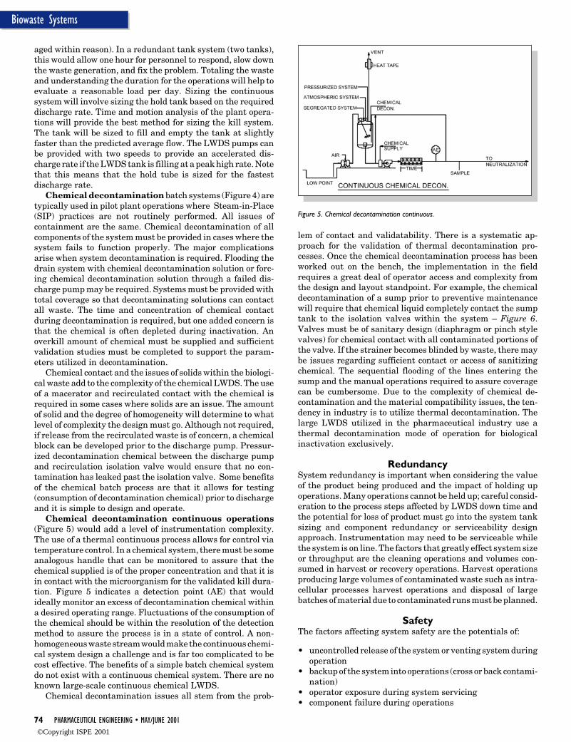
74 PHARMACEUTICAL ENGINEERING • MAY/JUNE 2001
Biowaste Systems
aged within reason). In a redundant tank system (two tanks),this would allow one hour for personnel to respond, slow downthe waste generation, and fix the problem. Totaling the wasteand understanding the duration for the operations will help toevaluate a reasonable load per day. Sizing the continuoussystem will involve sizing the hold tank based on the requireddischarge rate. Time and motion analysis of the plant opera-tions will provide the best method for sizing the kill system.The tank will be sized to fill and empty the tank at slightlyfaster than the predicted average flow. The LWDS pumps canbe provided with two speeds to provide an accelerated dis-charge rate if the LWDS tank is filling at a peak high rate. Notethat this means that the hold tube is sized for the fastestdischarge rate.
Chemical decontamination batch systems (Figure 4) aretypically used in pilot plant operations where Steam-in-Place(SIP) practices are not routinely performed. All issues ofcontainment are the same. Chemical decontamination of allcomponents of the system must be provided in cases where thesystem fails to function properly. The major complicationsarise when system decontamination is required. Flooding thedrain system with chemical decontamination solution or forc-ing chemical decontamination solution through a failed dis-charge pump may be required. Systems must be provided withtotal coverage so that decontaminating solutions can contactall waste. The time and concentration of chemical contactduring decontamination is required, but one added concern isthat the chemical is often depleted during inactivation. Anoverkill amount of chemical must be supplied and sufficientvalidation studies must be completed to support the param-eters utilized in decontamination.
Chemical contact and the issues of solids within the biologi-cal waste add to the complexity of the chemical LWDS. The useof a macerator and recirculated contact with the chemical isrequired in some cases where solids are an issue. The amountof solid and the degree of homogeneity will determine to whatlevel of complexity the design must go. Although not required,if release from the recirculated waste is of concern, a chemicalblock can be developed prior to the discharge pump. Pressur-ized decontamination chemical between the discharge pumpand recirculation isolation valve would ensure that no con-tamination has leaked past the isolation valve. Some benefitsof the chemical batch process are that it allows for testing(consumption of decontamination chemical) prior to dischargeand it is simple to design and operate.
Chemical decontamination continuous operations(Figure 5) would add a level of instrumentation complexity.The use of a thermal continuous process allows for control viatemperature control. In a chemical system, there must be someanalogous handle that can be monitored to assure that thechemical supplied is of the proper concentration and that it isin contact with the microorganism for the validated kill dura-tion. Figure 5 indicates a detection point (AE) that wouldideally monitor an excess of decontamination chemical withina desired operating range. Fluctuations of the consumption ofthe chemical should be within the resolution of the detectionmethod to assure the process is in a state of control. A non-homogeneous waste stream would make the continuous chemi-cal system design a challenge and is far too complicated to becost effective. The benefits of a simple batch chemical systemdo not exist with a continuous chemical system. There are noknown large-scale continuous chemical LWDS.
Chemical decontamination issues all stem from the prob-
lem of contact and validatability. There is a systematic ap-proach for the validation of thermal decontamination pro-cesses. Once the chemical decontamination process has beenworked out on the bench, the implementation in the fieldrequires a great deal of operator access and complexity fromthe design and layout standpoint. For example, the chemicaldecontamination of a sump prior to preventive maintenancewill require that chemical liquid completely contact the sumptank to the isolation valves within the system – Figure 6.Valves must be of sanitary design (diaphragm or pinch stylevalves) for chemical contact with all contaminated portions ofthe valve. If the strainer becomes blinded by waste, there maybe issues regarding sufficient contact or access of sanitizingchemical. The sequential flooding of the lines entering thesump and the manual operations required to assure coveragecan be cumbersome. Due to the complexity of chemical de-contamination and the material compatibility issues, the ten-dency in industry is to utilize thermal decontamination. Thelarge LWDS utilized in the pharmaceutical industry use athermal decontamination mode of operation for biologicalinactivation exclusively.
RedundancySystem redundancy is important when considering the valueof the product being produced and the impact of holding upoperations. Many operations cannot be held up; careful consid-eration to the process steps affected by LWDS down time andthe potential for loss of product must go into the system tanksizing and component redundancy or serviceability designapproach. Instrumentation may need to be serviceable whilethe system is on line. The factors that greatly effect system sizeor throughput are the cleaning operations and volumes con-sumed in harvest or recovery operations. Harvest operationsproducing large volumes of contaminated waste such as intra-cellular processes harvest operations and disposal of largebatches of material due to contaminated runs must be planned.
SafetyThe factors affecting system safety are the potentials of:
• uncontrolled release of the system or venting system duringoperation
• backup of the system into operations (cross or back contami-nation)
• operator exposure during system servicing• component failure during operations
Figure 5. Chemical decontamination continuous.
©Copyright ISPE 2001
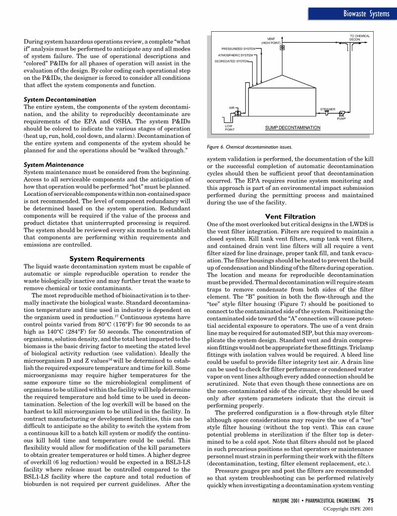
MAY/JUNE 2001 • PHARMACEUTICAL ENGINEERING 75
Biowaste Systems
During system hazardous operations review, a complete “whatif” analysis must be performed to anticipate any and all modesof system failure. The use of operational descriptions and“colored” P&IDs for all phases of operation will assist in theevaluation of the design. By color coding each operational stepon the P&IDs, the designer is forced to consider all conditionsthat affect the system components and function.
System DecontaminationThe entire system, the components of the system decontami-nation, and the ability to reproducibly decontaminate arerequirements of the EPA and OSHA. The system P&IDsshould be colored to indicate the various stages of operation(heat up, run, hold, cool down, and alarm). Decontamination ofthe entire system and components of the system should beplanned for and the operations should be “walked through.”
System MaintenanceSystem maintenance must be considered from the beginning.Access to all serviceable components and the anticipation ofhow that operation would be performed “hot” must be planned.Location of serviceable components within non-contained spaceis not recommended. The level of component redundancy willbe determined based on the system operation. Redundantcomponents will be required if the value of the process andproduct dictates that uninterrupted processing is required.The system should be reviewed every six months to establishthat components are performing within requirements andemissions are controlled.
System RequirementsThe liquid waste decontamination system must be capable ofautomatic or simple reproducible operation to render thewaste biologically inactive and may further treat the waste toremove chemical or toxic contaminants.
The most reproducible method of bioinactivation is to ther-mally inactivate the biological waste. Standard decontamina-tion temperature and time used in industry is dependent onthe organism used in production.17 Continuous systems havecontrol points varied from 80°C (176°F) for 90 seconds to ashigh as 140°C (284°F) for 50 seconds. The concentration oforganisms, solution density, and the total heat imparted to thebiomass is the basic driving factor to meeting the stated levelof biological activity reduction (see validation). Ideally themicroorganism D and Z values16 will be determined to estab-lish the required exposure temperature and time for kill. Somemicroorganisms may require higher temperatures for thesame exposure time so the microbiological compliment oforganisms to be utilized within the facility will help determinethe required temperature and hold time to be used in decon-tamination. Selection of the log overkill will be based on thehardest to kill microorganism to be utilized in the facility. Incontract manufacturing or development facilities, this can bedifficult to anticipate so the ability to switch the system froma continuous kill to a batch kill system or modify the continu-ous kill hold time and temperature could be useful. Thisflexibility would allow for modification of the kill parametersto obtain greater temperatures or hold times. A higher degreeof overkill (6 log reduction) would be expected in a BSL3-LSfacility where release must be controlled compared to theBSL1-LS facility where the capture and total reduction ofbioburden is not required per current guidelines. After the
system validation is performed, the documentation of the killor the successful completion of automatic decontaminationcycles should then be sufficient proof that decontaminationoccurred. The EPA requires routine system monitoring andthis approach is part of an environmental impact submissionperformed during the permitting process and maintainedduring the use of the facility.
Vent FiltrationOne of the most overlooked but critical designs in the LWDS isthe vent filter integration. Filters are required to maintain aclosed system. Kill tank vent filters, sump tank vent filters,and contained drain vent line filters will all require a ventfilter sized for line drainage, proper tank fill, and tank evacu-ation. The filter housings should be heated to prevent the buildup of condensation and blinding of the filters during operation.The location and means for reproducible decontaminationmust be provided. Thermal decontamination will require steamtraps to remove condensate from both sides of the filterelement. The “B” position in both the flow-through and the“tee” style filter housing (Figure 7) should be positioned toconnect to the contaminated side of the system. Positioning thecontaminated side toward the “A” connection will cause poten-tial accidental exposure to operators. The use of a vent drainline may be required for automated SIP, but this may overcom-plicate the system design. Standard vent and drain compres-sion fittings would not be appropriate for these fittings. Triclampfittings with isolation valves would be required. A bleed linecould be useful to provide filter integrity test air. A drain linecan be used to check for filter performance or condensed watervapor on vent lines although every added connection should bescrutinized. Note that even though these connections are onthe non-contaminated side of the circuit, they should be usedonly after system parameters indicate that the circuit isperforming properly.
The preferred configuration is a flow-through style filteralthough space considerations may require the use of a “tee”style filter housing (without the top vent). This can causepotential problems in sterilization if the filter top is deter-mined to be a cold spot. Note that filters should not be placedin such precarious positions so that operators or maintenancepersonnel must strain in performing their work with the filters(decontamination, testing, filter element replacement, etc.).
Pressure gauges pre and post the filters are recommendedso that system troubleshooting can be performed relativelyquickly when investigating a decontamination system venting
Figure 6. Chemical decontamination issues.
©Copyright ISPE 2001
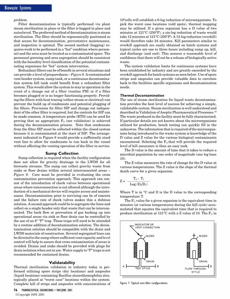
76 PHARMACEUTICAL ENGINEERING • MAY/JUNE 2001
Biowaste Systems
problem.Filter decontamination is typically performed via plant
steam sterilization in place or the filter is bagged in place andautoclaved. The preferred method of decontamination is steamsterilization. The filter should be ergonomically positioned sothat access for decontamination, preventative maintenance,and inspection is optimal. The second method (bagging) re-quires work to be performed in a “hot” condition where person-nel and the area must be treated as a contaminated space. Thepersonnel gowning and area segregation should be consistentwith the biosafety level classification of the potential contami-nating organisms for “hot” system intervention.
Redundant filters can be of benefit in several situations andcan provide a level of preparedness – Figure 8. A contaminatedvent header system, sump tank, or a continuous decontamina-tion system kill tank could benefit from a redundant filtersystem. This would allow the system to stay in operation in theevent of a change out of a filter (routine PM) or if a filterbecomes plugged or is no longer functioning properly. Provid-ing the filters with heat tracing (either steam or electrical) canprevent the build up of condensate and potential plugging ofthe filters. Provisions for filter SIP and change out indepen-dent of the other filter is required, but the controls for SIP canbe made common. A temperature probe (RTD) can be used forproving that an appropriate FO (see validation) is achievedduring the decontamination process. Note that condensatefrom the filter SIP must be collected within the closed systembecause it is contaminated at the start of SIP. The arrange-ment indicated in Figure 8 would provide a sufficiently sizedvent line to allow for condensate to run back in the vesselwithout affecting the venting operation of the filter in service.
Sump CollectionSump collection is required when the facility configuration
does not allow for gravity drainage to the LWDS for allbiowaste streams. The sump can collect gravity waste fromsinks or floor drains within several interconnected areas –Figure 9. Care must be provided in evaluating the crosscontamination prevention approach. This approach can con-sist of the introduction of check valves between operationalareas where interconnection is not allowed although the intro-duction of a mechanical device will require access and mainte-nance. Decontamination prior to servicing can be of concernand the failure rate of check valves makes this a dubioussolution. A second approach could be to segregate the lines andcollect on a single header only that waste that can be intercon-nected. The back flow or prevention of gas backing up intooperational areas via sink or floor drain can be controlled bythe use of an 8" “P” trap. These traps will need to be attendedby a routine addition of decontamination solution. The decon-tamination solution should be compatible with the drain andLWDS materials of construction. Several segregated lines canbe directed to the sump where sufficient vent capacity and levelcontrol will help to assure that cross contamination of areas isavoided. Drains and sinks should be provided with plugs fordrain isolation when not in use. Water supply to “P” traps is notrecommended for contained drains.
ValidatabilityThermal sterilization validation in industry today is per-formed utilizing spore strips (dry locations) and ampoules(liquid locations) containing Bacillus stearothemophilus stra-tegically placed at “worst case” locations within the system.Complete kill of strips and ampoules with concentrations of
106cells will establish a 6-log reduction of microorganisms. Topick the worst case locations (cold spots), thermal mappingmay be utilized. If a given organism has a D value of twominutes at 121°C (250°F), a six-log reduction of waste wouldtake 12 minutes at 121°C (250°F). A 12-log reduction (overkill)would therefore take 24 minutes. Kill parameters similar tooverkill approach are easily obtained on batch systems andtypical cycles are one to three hours including ramp up, kill,and discharge (and cool). This assures a reasonable level ofconfidence that there will not be a release of biologically activewaste.
The system validation limits for continuous systems havebeen established by industry and are greatly exceeded by theoverkill approach for batch systems as seen below. Use of sporestrips and ampoules can provide valuable data to correlateback to the facilities specific organisms and decontaminationneeds.
Thermal DecontaminationThe use of steam sterilization for liquid waste decontamina-tion provides the best level of success for achieving a simple,validatable system. Steam sterilization is well understood anddescribed in Validation of Aseptic Pharmaceutical Processes.16
The waste produced in the facility must be fully characterized.If particular details are not known about the microorganismsutilized for production, bench testing can quickly fill in theunknowns. The information that is required of the microorgan-isms being introduced to the waste system is knowledge of theD value and Z value for the various biological contaminantsencountered. Selecting the FO that will provide the requiredlevel of kill assurance is then an easy task.
The D value is the amount of time that it takes to reduce amicrobial population by one order of magnitude (one log base10).
The Z value measures the rate of change for the D value atvarious temperatures. The Z value is the slope of the thermaldeath curve for a given organism.
T2 – T1Z = _____________
Log (D2/D1)
Where T is in °C and D is the D value to the correspondingtemperature T.
The FO value for a given organism is the equivalent time inminutes (at various temperatures during the kill cycle) accu-mulated that equates the equivalent time that is required toproduce sterilization at 121°C with a Z value of 10. The FO in
Figure 7. Typical vent filter configurations.
©Copyright ISPE 2001
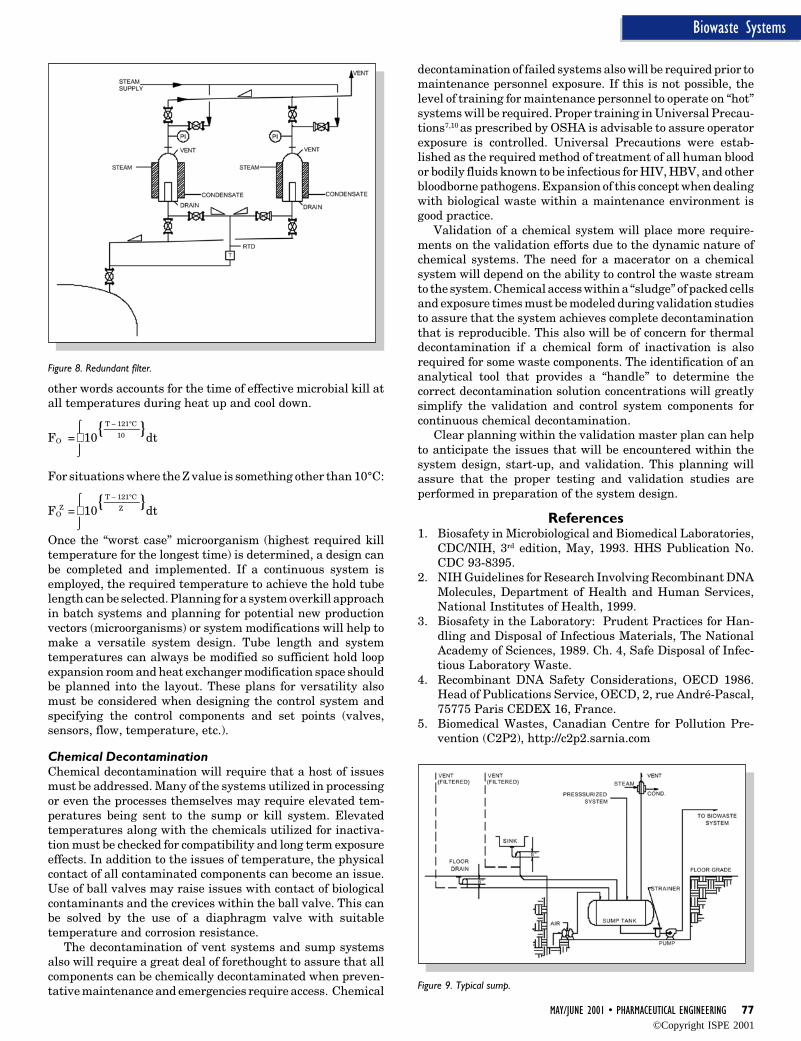
MAY/JUNE 2001 • PHARMACEUTICAL ENGINEERING 77
Biowaste Systems
Figure 8. Redundant filter.
other words accounts for the time of effective microbial kill atall temperatures during heat up and cool down.
⌠ T – 121°C
FO = 10{______}dt
⌡10
For situations where the Z value is something other than 10°C:
Z
⌠ T – 121°C
FO = 10{______}dt
⌡Z
Once the “worst case” microorganism (highest required killtemperature for the longest time) is determined, a design canbe completed and implemented. If a continuous system isemployed, the required temperature to achieve the hold tubelength can be selected. Planning for a system overkill approachin batch systems and planning for potential new productionvectors (microorganisms) or system modifications will help tomake a versatile system design. Tube length and systemtemperatures can always be modified so sufficient hold loopexpansion room and heat exchanger modification space shouldbe planned into the layout. These plans for versatility alsomust be considered when designing the control system andspecifying the control components and set points (valves,sensors, flow, temperature, etc.).
Chemical DecontaminationChemical decontamination will require that a host of issuesmust be addressed. Many of the systems utilized in processingor even the processes themselves may require elevated tem-peratures being sent to the sump or kill system. Elevatedtemperatures along with the chemicals utilized for inactiva-tion must be checked for compatibility and long term exposureeffects. In addition to the issues of temperature, the physicalcontact of all contaminated components can become an issue.Use of ball valves may raise issues with contact of biologicalcontaminants and the crevices within the ball valve. This canbe solved by the use of a diaphragm valve with suitabletemperature and corrosion resistance.
The decontamination of vent systems and sump systemsalso will require a great deal of forethought to assure that allcomponents can be chemically decontaminated when preven-tative maintenance and emergencies require access. Chemical
decontamination of failed systems also will be required prior tomaintenance personnel exposure. If this is not possible, thelevel of training for maintenance personnel to operate on “hot”systems will be required. Proper training in Universal Precau-tions7,10 as prescribed by OSHA is advisable to assure operatorexposure is controlled. Universal Precautions were estab-lished as the required method of treatment of all human bloodor bodily fluids known to be infectious for HIV, HBV, and otherbloodborne pathogens. Expansion of this concept when dealingwith biological waste within a maintenance environment isgood practice.
Validation of a chemical system will place more require-ments on the validation efforts due to the dynamic nature ofchemical systems. The need for a macerator on a chemicalsystem will depend on the ability to control the waste streamto the system. Chemical access within a “sludge” of packed cellsand exposure times must be modeled during validation studiesto assure that the system achieves complete decontaminationthat is reproducible. This also will be of concern for thermaldecontamination if a chemical form of inactivation is alsorequired for some waste components. The identification of ananalytical tool that provides a “handle” to determine thecorrect decontamination solution concentrations will greatlysimplify the validation and control system components forcontinuous chemical decontamination.
Clear planning within the validation master plan can helpto anticipate the issues that will be encountered within thesystem design, start-up, and validation. This planning willassure that the proper testing and validation studies areperformed in preparation of the system design.
References1. Biosafety in Microbiological and Biomedical Laboratories,
CDC/NIH, 3rd edition, May, 1993. HHS Publication No.CDC 93-8395.
2. NIH Guidelines for Research Involving Recombinant DNAMolecules, Department of Health and Human Services,National Institutes of Health, 1999.
3. Biosafety in the Laboratory: Prudent Practices for Han-dling and Disposal of Infectious Materials, The NationalAcademy of Sciences, 1989. Ch. 4, Safe Disposal of Infec-tious Laboratory Waste.
4. Recombinant DNA Safety Considerations, OECD 1986.Head of Publications Service, OECD, 2, rue André-Pascal,75775 Paris CEDEX 16, France.
5. Biomedical Wastes, Canadian Centre for Pollution Pre-vention (C2P2), http://c2p2.sarnia.com
Figure 9. Typical sump.
©Copyright ISPE 2001

78 PHARMACEUTICAL ENGINEERING • MAY/JUNE 2001
Biowaste Systems
6. Kearns, Michael J., “Containment of Biological Hazards:Effect of Guidelines on the Design of PharmaceuticalFacilities and Process Equipment,” Pharmaceutical En-gineering, July/August 1989, 17-21.
7. Laboratory Biosafety Guidelines, Medical Research Coun-cil and Health and Welfare Canada, 1990, revised atUniversity of Toronto, 1997.
8. NREL Biosafety Program, Environment, Safety & HealthOffice, http://www.nrel.gov/esh/manual/6-4_11.html
9. NIGMS Human Genetic Mutant Cell Repository MinimumSafety Guidelines, http://arginine.umdnj.edu
10. OSHA Bloodborne Pathogens, Occupational Safety andHealth Administration, US Department of Labor, http://www.osha-slc.gov
11. OSHA Standards Interpretation and Compliance Letters,Occupational Safety and Health Administration, US De-partment of Labor, http://www.osha-slc.gov
12. 40 CFR Ch1 (7-1-99) Part 439- Pharmaceutical Manufac/www.stichemclav.com
16. Carleton, Frederick J. and Agalloco James P., eds., Valida-tion of Aseptic Pharmaceutical Processes, Marcel Dekker,Inc., New York.
17. Fox, Sandra, “Process and Equipment Requirements forSterilization of Biological Wastes,” Genetic EngineeringNews, January 1991, 6-7.
18. Petrosslan, Ashot, Smart, Niget and Proletto, Robert P.,“Designing a Flexible Facility for Biopharmaceuticals,”BioPharm, July-Aug 1993, 40-45.
19. Principles and Design of Pharmaceutical Production Fa-cilities, Biotechnology International, 367-370.
20. Shahidi, Ahmad J., Eliezer, Eddy and Johnson, Harry L.,Design Considerations for a Recombinant DNA ProteinProduction Facility, Biotechnology International, 387-399.
21. Shahadi, Ahmad J.,Torregrossa, Robert and Zelmanovich,Yasha, “Design Concepts for Multi-Product Biotech Facili-ties,” Pharmaceutical Engineering, September/Octo-ber 1995, 72-83.
22. Waste Incineration, GUA-Gesellschaft fur umfassendeAnalysen GmbH, http://www.gua.at/english/texts/waste_inc.htm
23. Baum, Janet S., Design Features of Biotechnology Labora-tory Environment, Occupational Medicine: State of the ArtReviews, Hanley & Belfus, Inc., Philadelphia, April-June,1991, 227-254.
24. Crumbly, Liz, BioConverter System Safely Treats InfectiousMedical Waste, Virginia Tech Spectrum, July 13, 1995.
25. Denys, Gerald, A., Microbiological Evaluation of the Medi-cal Safetec Mechanical/Chemical Infectious Waste Dis-posal System, 89th Annual Meeting of the American Societyfor Microbiology, May 16, 1989.
26. Geoghegan, Richard F. and Meslar, Harry W.,“Biocontainment Facilities Theory and Practice,” Pharma-ceutical Engineering, November/December 1991, 27-33.
27. Giorgio, Robert J., and Wu, James J., Design of Large ScaleContainment Facilities for Recombinant DNA Fermenta-tions, Tibtech, March 1986, 60-65.
28. Hampshire, John B., and Leone, Louis, Designing of BulkPharmaceutical Pilot Plants.
29. Hill, Donald and Beatrice, Michael, “Facility Require-ments for Biotech Plants,” Pharmaceutical Engineer-ing, July/August 1989, 35-41.
30. Hill, Donald and Beatrice, Michael, “Biotechnology Facil-ity Requirements,” BioPharm, October 1989, 20-24.
31. Huddy, Paul, Total Containment of Bioreactors, Biotech-nology International, 384-386.
About the AuthorCarl J. Carlson is the Executive Vice President of PhoenixImperative Inc. He has more than 15 years of industrialexperience in the diagnostic and pharmaceutical industries.Experience spans from operations in development/scale-up/production to the design and integration of processes in pro-duction or pilot facilities. The integration of manufacturingexpertise, process engineering, process control, current GoodManufacturing Practices (cGMPs), and compliance, providesan ideal background for quality facility and process designexperience. The design and integration of critical utilities, up-stream processing, and downstream processing is all focusedon serving the GMP envelope where critical decisions aremade. Carlson’s design experience within the GMP envelopehas integrated this process knowledge from bench scale pilotplants up to facilities producing kilogram quantities. Process-ing and design experience includes scale-up and developmentof conjugation, derivatization, purification, and/or extraction,of proteins, oligosaccharides, polysaccharides, sugars, glyco-proteins, etc. He is a member of ISPE, American ChemicalSociety (ACS), American Institutes of Chemists (AIC), Instru-ment Society of America (ISA).
Phoenix Imperative Inc., 225 Corporate Blvd., Suite 204,Newark, DE 19702.
©Copyright ISPE 2001