Embed Size (px)
Citation preview
Form3160-3l
(August 2007)
(RECEIVE ' JUL 2 3 2013
UNITED STATES DEPARTMENT OF THE INTERIOR ADTC« BUREAU OF LAND MANAGEMENT ^ r • ^ ^ H J f c j
APPLICATION FOR PERMIT TO DRILL OR REENTER
FORM APPROVED OMB.No. I004-OI37.
Expires July 31, 2010
5. Lease Serial No. [NMLC 028936C
T •4 6. If Indian, Allotee or Tribe Name
la. Type of work: [ T J D R I L L • REENTER
lb. Type of Well: [7J Oil Well Q Gas Well Q Other [ 7 ] Single Zone • Multiple Zone
7 If Unit or C A Agreement, Name and No.
8. Lease Name and Well No. Federal S#008
1 Name of Operator Alamo Permian Resources, LLC OGRID #274841 9. API Well No. , r J
3a. Address 415 W. Wall Street, Suite 500 Midland, TX 79701
3b. Phone No. (include area code)
(432) 897-0673 10. Field and Pool, or Exploratory
Grayburg Jackson; SR-Q-G-SA ^ ^ 0 7 ^
4. Location of Well (Report location clearly and in accordance with any State requirements.*)
At surface 880' FSL & 330' FWL, Unit M
- At proposed prod, zone •
11. Sec., T. R. M. or Blk. and Survey or Area
Sec28;T-17S;R-30E
14. Distance in miles and direction from nearest town or post office* Approximately 1 mile south from Loco Hills, New Mexico
12. County or Parish Eddy
13. State NM
15. Distance from proposed* location to nearest property or lease line, f t (Also to nearest drig. unit line, if any)
16. No. of acres in lease
240
17. Spacing Unit dedicated to this well
40 acres
18. Distance from proposed location* igso' to nearest well, drilling, completed, applied for, on this lease, ft.
19. Proposed Depth
3400'
20. BLM/BIA Bond No. on file
NMB000741 «t 7*>^
21. Elevations (Show whether DF, KDB, RT, GL, etc.) 3616.9'GL
22 Approximate date work will start*
08/15/2013
23. Estimated duration
30-45 days
24. Attachments The following; completed in accordance, with the requirements of Onshore Oil and Gas Order No.l, must be attached to this form:
1. Well plat certified by a registered surveyor. 1 A Drilling Plan. 3. A Surface Use Plan (if the location is on National Forest System Lands, the
SUPO must be filed with the appropriate Forest Service Office).
4. Bond to cover the operations unless covered by an existing bond on file (see Item 20 above).
5. Operator certification 6. Such other site specific information and/or plans as may be required by the
BLM.
Name (Printed/Typed) Vicki Johnston
Date 05/31/2013.
Tide
Gray Surface Specialties, Agent for Alamo Permian Resources, LLC
Approved by (Signature) / s / G e O T Q e M a C D o n e l l Name M a C D o n e l l Date JUL 1 6 2013 T l , l e FIELD MANAGER
Office
CARLSBAD FIELD OFFICE Application approval does not warrant or certify that the applicant holds legal or equitable title to those rights in the subject lease which would entitle the applicant to conduct operations thereon. .Conditions ofapproval, if any, are attached. A P P R O V A L F O R T W O Y E A R S
Title 18 U.S.C. Section 1001 andTitle 43 U.S.C. Section 1212, make it a crime for any person knowingly and willfully to niake to any department or agency ofthe United States any false, fictitious or fraudulent statements or representations as to any matter within its jurisdiction.
(Continued on page 2) •(Instructions on page 2)
Roswell Controlled Water Basin
SEE ATTACHED FOR CONDITIONS OF APPROVAL ApprovaTSubiect to General Requirements
& Special Stipulations Attached

mmriai !M5 'N. P twd i Dr.. Hobbs. NMSM40 Pfcohc ({?5I . 'V -o Ih i - f ta : (57>> J')J-0"':6 nislriL'S II
ji 11 s.- r-it-st si.. Aiiosia. NM ss;io Phone: (J73) "4S-I2S3 (57;j'74S-9v;ij |5isiia.l.U iOOO Rio Urazos Read. Aztec. NM 57410
Plume: 1505) J344I3S F K : (505) 3544110
C:0 S: St. l:r;mcis:Dr.. Snnin Ft:. NM PRonc (505) 4"G-«I60 l-'ax: (505) 475-.M62
EXHIBIT A
State of New Mexico Energy, Minerals & Natural Resources Department
OIL CONSERVATION DIVISION 1220 South St. Francis Dr.
Santa Fe NM 87505
WELL LOCATION AND ACREAGE DEDICATION PLAT
n CM02 (-onn < Revised August t , 2011
Submit one copy to appropriate District Office
• AMENDED REPORT
St . ' API Nunta '"Pool'Code ., ' } *' Pool Name
Grayburg Jackson; SR-Q-G-SA _ — ; 1
Property Code ' . f Property Name 6 Weil Number
308456v FEDERAL S -008 'OGRID No. • .* Operator Name * Elevation
274841 ALAMO PERMIAN RESOURCES, LLC 3616.9
"• Surface Location : UI. or lot no. Section Township ' Ran«e Lot Idn . Fect from the North/South line Feet.from the ' EastAVest line County
M 28 17 S ' 30 E . ' 880 ; SOUTH 330 WEST." EDDY
" Bottom Hole Location If Different From Surface UL or tot no. Section Township Ran«c • Lot Idn Feet from the North/South line Keet from tKe KiistAVest'Iinc County.
" Dedicated Acres
40
1 1 Joint or Infill 1 4 Consolidation Code : 1 5 Order No. ; \ "
No allowable will be assigned to this completion until all interests have been consolidated or a non-standard unit has been approved by the division. .
S89'52'b8"W ~ 2641-19 FT S89-53'13"W '2541.89 FT Wl CORNER SEC. 28 LAT. = 32'48'45.986"N I LONG. = I03'59'08.002"W|
N QUARTER CORNER SEC 2 LAT. = 32'43'45.959?N
LOMG. = !03'58'37.061"W !
! NE CORNER SEC. 28 I LAT. .= 32'48'45.921 "N i LOMG. = 103'58'Oe.l 12"W
I
'fl QUARTER CORNER. 5EC, 2S UTT=^2TaT9.8T4TT T ~ LONG. = 103'59'08.003"W !
_E ^ARJER_C0RMER SECLJ8 i LAT. = 32"48'19.a09"ri I LONG. •= 103'58'O6.128>
FEDERAL l S §008 • EtEV.. = 3618.9' i LAT. = 32'43 -02.+55"N (NAD83) >
•• 1 0 J ' 5 9 ' 0 3 . 9 4 4 " W 1 LONG.
SURFACE LOCATION
SW-CORNER SEC U t : = 3Z47'53 inwr: =. in-yw
753"N 714'«
I S QUARTER CORNER. SEC. 28
LAT. = 32'47'53.720:M LONG. = I03;58,37.055"W
I SE CORNER SEC. 28 j LAT. = ,32'47'53.686"N , LONG. = 103'58'06.137"'fl
M89'52'55"E - 261,7.49 FT N89'52:5lt 2639.70 FT
" OPERATOR CERTIFICATION IforttyCcmify ;hat the biformauon zowidttfii herein izmtewtd compile
IQ t!n> fV.fr of my knovdedge andbelkj.'and dmt dasoi^ardztitimieither
o»>« a \wrkiu% interest or uidmsed mineral interest m (lie Ittiuf including
the pnqmed hoiiota half localion or has a right todiill litis »erV at this
lixation pursuant X? a comma HIV// an onnfir of such a mineral or uviiing
imavst, or to a wtumnrypooling agreement or a cpmptdsuryponl'iitg
orderf-^mqf^ enti<nf^^e dmswn.
Carl Dl Campbell Primed Name- * '• '
[email protected] E-maii Address.
'"SURVEYOR CERTIFICATION / hereby certify lhat the veil location shown on this
plat was plotted front field notes of actual surveys
made, by me.or muter my supervision, and that the same-is triie^WKl hoM'ClYdllu' beit d(mv belief:
JANUARV2>20I3 , -S'.-..
J A R A M I L L a I'LS 12797
SURVEY NO.T430A

Alamo Permian Resources, L L C Federal S #008
SHL: 880' FSL & 330' FWL, Unit M Sec 28 T-17S R-30E
Eddy County, New Mexico
OPERATOR CERTIFICATION
I hereby certify that I , or persons under my direct supervision, have inspected the proposed drill site and access route; that I am familiar with the conditions which presently exist; that I have full knowledge of state and Federal laws applicable to this operation; that the statements made in this Application for Permit to Drill (APD) package are, to the best of my knowledge, true and correct; and that the work associated with the operations proposed herein will be performed by Alamo Permian Resources, LLC, and its contractors and subcontractors in conformity with this APD Package and the terms and conditions under which it is approved. These statements are subject to the provisions of 18 U.S.C. 1001 for the filing of a false statement.
Carl D. Campbell Chief Operating Officer Alamo Permian Resources, LLC
Date
Office Phone: (713) 224-2500 Cell Phone: (713)299-1353 E-mail: [email protected]
I 'ERMiAN RESOURCES, U C
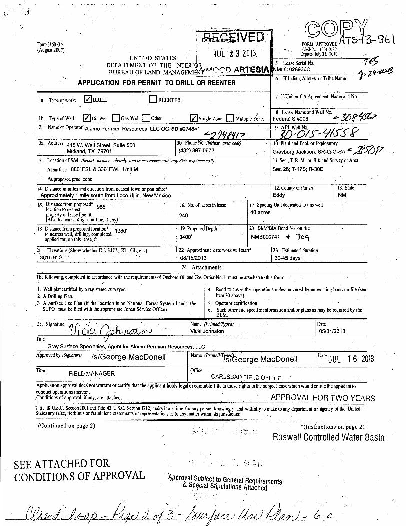
January 28,-2013
Bureau of Land Management Attention: Legal Instrument Examiners 620 East Greene Street Carlsbad, New Mexico 88220
Re: AGENT AUTHORIZATION
To Whom It May Concern:
Please be informed that Vicki Johnston is an Agent employed by Gray Surface Specialties, 3106 N. Big Spring, Suite 100, .Midland, Texas, 79705. -She is authorized to prepare: and submit APDs, Sundry Notices, Right-of-Way application, and other BLM-required forms on behalf of Alamo. Permian Resources, LLC (OGRID #274841).
Vicki can be contacted as follows:
Mailing Address: 116 White Oak Jrall, Bderne, Texas 78006 Telephone: (830) 537-4599 (office) or (281) 468-2448 (cell) E-mail: [email protected]
Sincerely,
Carl D. Campbell
Chief Operating Officer
82 0 GESSNER RD, SUITE 16 50 H O U S T O N , TEXAS • 7 7 0 2 4
P H O N E : 7 1 3 . 2 2 4 . 2 5 0 0 f-AX : 713.22 4.6 0 96

EXHIBIT B-1
WrSECTWN 28, TOWNSHIP 17 SOUTH, RANGE 30 EAST, N.M.P.M^ EDDY COUNTY, STATE OF NEW MEXICO
EL. 3619.3' I "
in i f )
to
150' WEST I OFFSET I I
EL. 3619.6^1
I EL. 3617.0'
010 50 100 200
600' EL. 3621.7' 1
150' NORTH OFFSET
EL. 3518.3'
i 300 -PROPOSED PAD-
2.067 ACRES
FEDERAL S #008 ELEV. 4 3616.9'
LAT. = 32,48'02.455"N (NA083) LONG. = 103"59'03.944"W
200'
150 EAST | OFFSET EL 3613.5'
300'
150' SOUTH OFFSET
EL. 3618.4'
O O
PROPOSED 39R LF ACCESS ROAD T0-
12* CALICHE ROAD
600 EL. I
3614.1'
>
SCALE 1 = 100' DIRECTIONS TO LOCATION FROM INTERSECTION OF STATE HIGHWAY 82 AND CR 217 GO SOUTH ON CR 217 APPROX. 0.4 MILES TO THE MIDDLE OF CURVE THAT CURVES RIGHT IS A LEASE ROAD ON LEFT (SOUTHEAST) OF CURVE-TURN LEFT (SOUTHEAST) GO APPROX. 0.8 MILES TO A PUMP JACK ON RIGHT (SOUTH). TURN RIGHT ON ROAD TO PUMP JACK AT SOUTHWEST CORNER OF PAD IS A LEASE ROAD GOING SOUTH. FOLLOW ROAD APPROX. 0.4 MILES TO A ROAD LATH WITH RED AND WHITE RIBBON ON RIGHT SIDE (WEST) OF ROAD. LOCATION IS APPROX. 400 FT ±.
MADRON SURVEYING, INC.
ALAMO PERMIAN RESOURCES, LLC FEDERAL S §008
LOCATED 880 FT. FROM THE SOUTH LINE AND 330 FT. FROM THE WEST LINE OF
SECTION 28, TOWNSHIP 17 SOUTH, RANGE 30 EAST, N.M.P.M.
EDDY COUNTY, STATE OF NEW MEXICO
61 30! KX:TH <S?S) 2:54-.
JANUARY 30, 2013
SURVEY NO. 1450A CARLSBAD, NEW MEXICO

EXHIBIT B-2
19 20 BC 1918 „ (
30 29
ACCESS ROAD FOR FEDERAL S #008 AND #009
ALAMO PERMIAN RESOURCES, LLC CENTERLINE SURVEY OF AN ACCESS ROAD CROSSING
SECTION 29, TOWNSHIP 17 SOUTH, RANGE 30 EAST, N.M.P.M. EDDY COUNTY, STATE OF NEW MEXICO
JANUARY 30, 2013
Sa9'51'14"W 2640.71 FT . . ^1916 STA 0+00 tedN MAIN UNE ACCESS ROAD
30 29
BC 1916 31 32
N89M9 18"E 2653.43 FT N a g ^ ' i s - E 2653.43 FT
29 28 i m BC 1916
32 33
DESCRIPTION A STRIP OF LAND 30 FEET WIDE CROSSING BUREAU OF LAND MANAGEMENT LAND IN SECTION 29. TOWNSHIP 17 SOUTH. RANGE 30 EAST. N.M.P.M.. EDDY COUNTY. STATE OF NEW MEXICO AND BEING 15 FEET EACH SIDE OF THE FOLLOWING DESCRIBED CENTERLINE SURVEY:
BEGINNING AT A POINT WITHIN THE NE/4 NE/4 OF SAID SECTION 29. TOWNSHIP 17 SOUTH, RANGE 30 EAST, N.M.P.M.. WHENCE THE NORTHEAST CORNER OF SAID SECTION 29. TOWNSHIP 17 SOUTH, RANGE 30 EAST. N.M.P.M. BEARS N89"43'02"E, A DISTANCE OF 364.15 FEET; THENCE S4i:28"58"E A DISTANCE OF 211.50 FEET TO AN ANGLE POINT OF THE UNE HEREIN DESCRIBED: THENCE S38'56'58"E A DISTANCE OF 358.70 FEET THE TERMINUS OF THIS CENTERUNE SURVEY, WHENCE THE NORTHEAST CORNER OF SAID SECTION 29, TOWNSHIP 17 SOUTH. RANGE 30 EAST. N.M.P.M. BEARS NOOMI'MV, A DISTANCE OF 439.20 FEET;
SAID STRIP OF LAND BONG 570.20 FEET OR 34.56 RODS IN LENGTH, CONTAINING 0.393 ACRES MORE OR LESS AND BEING ALLOCATED BY FORTIES AS FOLLOWS:
NE/4 NE/4 570.20 LF. 34.56 RODS 0.393 ACRES
GENERAL NOTES 1. ) THE INTENT OF THIS ROUTE SURVEY IS TO ACQUIRE AN EASEMENT.
2. ) BASIS OF BEARING IS NMSP EAST MODIFIED TO SURFACE COORDINATES.
^ SHEET: 1-5
MADRON SURVEYING,
SURVEYOR CERTIFICATE
I, F1UMON F. JARAMILLO. A NEW MEXICO PROFESSIONAL SURVEYOR NO. 12797, HEREBY CERTIFY THAT I HAVE CONDUCTED AND AM RESPONSIBLE FOR THIS SURVEY, THAT THIS SURVEY IS TRUE AND, CORRECT TO THE BEST OF MY KNOWLEDGE AND BELIEF, AND THAT THIS SURVEYCAND'.eLAT MEET THE MINIMUM STANDARDS FOR LAND SURVEYING IN THE STATE OF NEWfMEXiCO.
•iv-$V . , ' <'/s''r IN WITOESS'WHEREOF/THiSiCERWICATE IS EXECUTED AT CARLSBAD.
NEW AMEXICO,-£HIS i l l DAY .OF JANUARY 2013 . l lV? - MADRON SURVEYING, INC.
--T^l n - ~ 301 SOUTH CANAL J I CARLSBAD; NEW MEXICO 88220
^Phone (575) 234-3341
SURVEY NO. 1494A
W$Ulf, NEW MEXICO

EXHIBIT B-3
ACCESS ROAD FOR FEDERAL S #008 AND #009
ALAMO PERMIAN RESOURCES, LLC CENTERLINE SURVEY OF AN ACCESS ROAD CROSSING
SECTION 28, TOWNSHIP 17 SOUTH, RANGE 30 EAST, N.M.P.M. EDDY COUNTY, STATE OF NEW MEXICO
JANUARY 30, 2013
20 21 AC 188 u |
29 28
21 22 ^BC 1918
28 27
28 27 1 J BC 191B
33 34
DESCRIPTION A STRIP OF LAND 30 FEET WIDE CROSSING BUREAU OF LAND MANAGEMENT LAND IN SECTION 28, TOWNSHIP 17 SOUTH. RANGE 30 EAST, N.M.P.M., EDDY COUNTY, STATE OF NEW MEXICO AND BEING 15 FEET EACH SIDE OF THE FOLLOWING DESCRIBED CENTERLINE SURVEY:
BEGINNING AT A POINT WITHIN THE NW/4 NW/4 OF SAID SECTION 28. TOWNSHIP 17 SOUTH, RANGE 30 EAST. N.M.P.M., WHENCE THE NORTHWEST CORNER OF SAID SECTION 28, TOWNSHIP 17 SOUTH, RANGE 30 EAST, N.M.P.M. BEARS NOOT1V14"W, A DISTANCE OF 439.20 FEET; THENCE S i S ^ ' s a T A DISTANCE OF 248.72 FEET TO AN ANGLE POINT OF THE UNE HEREIN DESCRIBED; THENCE S38-43'33"E A DISTANCE OF 304.71 FEET TO AN ANGLE POINT OF THE UNE HEREIN DESCRIBED; THENCE S 3 r i 4 ' 5 8 * E A DISTANCE OF 603.33 FEET TO AN ANGLE POINT OF THE UNE HEREIN DESCRIBED; THENCE S39 ,28'44"E A DISTANCE OF 304.35 FEET TO AN ANGLE POINT OF THE UNE HEREIN DESCRIBED; THENCE S38-i3'51"E A DISTANCE OF 602.63 FEET TO AN ANGLE POINT OF THE UNE HEREIN DESCRIBED; THENCE S3749'57*E A DISTANCE OF 907.72 FEET TO AN ANGLE POINT OF THE UNE HEREIN DESCRIBED; THENCE S3T51\35"E A DISTANCE OF 613.66 FEET TO AN ANGLE POINT OF THE UNE HEREIN DESCRIBED: THENCE S37-27'59"E A DISTANCE OF 19.65 FEET TO AN ANGLE POINT OF THE UNE HEREIN DESCRIBED; THENCE S4C16'32'W A DISTANCE OF 99.44 FEET TO AN ANGLE POINT OF THE LINE HEREIN DESCRIBED: THENCE S73 i55'12"W A DISTANCE OF 123.15 FEET TO AN ANGLE POINT OF THE UNE HEREIN DESCRIBED; THENCE S79 -50'22"W A DISTANCE OF 176.20 FEET TO AN ANGLE POINT OF THE'UNE HEREIN DESCRIBED: THENCE S43-50'50"W A DISTANCE OF- 425.96 FEET TO AN ANGLE POINT OF THE UNE HEREIN DESCRIBED: THENCE S38-12 ,19"W A DISTANCE OF 179.55 FEET TO AN ANGLE POINT OF THE UNE HEREIN DESCRIED; THENCE S35 -58'27"W A DISTANCE OF 208.09 FEET TO AN ANGLE POINT OF THE UNE HEREIN DESCRIBED; THENCE S36-42'55"W A DISTANCE OF 671.05 FEET TO AN ANGLE POINT OF THE UNE HEREIN DESCRIBED: THENCE SSe-SO'UT* A DISTANCE OF 63.72 FEET TO AN ANGLE POINT OF THE LINE HEREIN DESCRIBED; THENCE N85-07'22"W A DISTANCE OF 392.04 FEET THE TERMINUS OF THIS CENTERUNE SURVEY. WHENCE THE SOUTHWEST CORNER OF SAID SECTION 28, TOWNSHIP 17 SOUTH. RANGE 30 EAST. N.M.P.M. BEARS S34'10'40"W. A DISTANCE OF 834.76 FEET;
SAID STRIP- OF LAND BEING 5943.97 FEET OR 360.24 RODS IN LENGTH, CONTAINING 4.094 ACRES MORE OR LESS AND BEING ALLOCATED BY FORTIES AS FOLLOWS:
NW/4 NW/4 S W / 4 N W / 4 SE/4 NW/4 NE/4 SW/4 SE/4 SW/4 SW/4 SW/4
1116.65 LF. 1024.87 LF. 653.58 LF.
1927.56 LF. 94.87 LF.
1126.44 LF.
67.68 RODS 62.11 RODS 39.61 RODS
116.82 RODS 5.75 RODS
68.27 RODS
0.769 ACRES 0.706 ACRES 0.450 ACRES 1.328 ACRES 0.065 ACRES 0.776 ACRES
SURVEYOR CERTIFICATE
I, F1UM0N F. JARAMILLO. A NEW MEXICO PROFESSIONAL SURVEYOR NO. 12797, HEREBY CERTIFY THAT I .HAVE CONDUCTED AND AM RESPONSIBLE FOR THIS SURVEY, THAT THIS-SURVEYjlS't TRUE/AND CORRECT TO THE BEST OF MY KNOWLEDGE AND B E U E F J ^ A N D M B A T THIS' SURVEY-AND PLAT MEET THE MINIMUM STANDARDS FOR LAND
GENERAL NOTES \ . ) THE INTENT OF THIS ROUTE SURVEY IS TO ACQUIRE AN EASEMENT.
2.) BASIS OF BEARING IS NMSP EAST MODIFIED TO SURFACE COORDINATES.
T SHEET: 2-5
MADRON SURVEYING, L
SURVEYING,.IN THEiSTATE'OFiNEW MEXICO.
- - ^ I N WITNESS WHEREOF,'THIS-CERT1FICATE IS.EXECUTED AT CARLSBAD, -U . : — > , O -
NEW MEXICO. .THIS J / DAY OF JANUARY 2013 ' 1 ' ' MADRON SURVEYING. INC.
301 SOUTH CANAL CARLSBAD. NEW MEXICO 86220 Phone (575) 234-3341
SURVEY NO. 1494A,
W.yh^'dM^SBAD, NEW MEXICO

EXHIBIT B-4
ACCESS ROAD FOR FEDERAL S' #008 AND #009
ALAMO PERMIAN RESOURCES, LLC CENTERLINE SURVEY OF AN ACCESS ROAD CROSSING
SECTION 28, TOWNSHIP 17 SOUTH, RANGE 30 EAST, N.M.P.M. EDDY COUNTY, STATE OF NEW MEXICO
JANUARY 30, 2013
20 21 AC 198 p (
29 28
S 6 9 ' 5 2 ' 0 8 " W 2 6 4 1 . 1 9 FT
| 1000
1/2" PIPE S 8 9 ' 5 3 ' 1 3 " W | 2 6 4 1 . 8 9 FT
1000 |
^ I I
SEQ 28 TJJS^,\R.30E.
BLM
21 22 ( t B C 1916
28 27
STA'5+66.5 END LATERAL 1
- H • - : h'
STA I 0+00 START LATERAL TO FEDERAL S #009 | STA 57+44.4 MAIN LINE
N 8 9 ' 5 2 ' 5 r E 2 6 3 9 . 7 0 FT
28 27 1 * BC 1916
33 34
DESCRIPTION A STRIP OF LAND 30 FEET WIDE CROSSING BUREAU OF LAND MANAGEMENT LAND IN SECTION 28 , TOWNSHIP 17 SOUTH. RANGE 30 EAST. N.M.P.M.. EDDY COUNTY. STATE OF NEW MEXICO AND BEING 15 FEET EACH SIDE OF THE FOLLOWING DESCRIBED CENTERLINE SURVEY:
BEGINNING AT A POINT WITHIN THE SW/4 S W / 4 OF SAID SECTION 28, TOWNSHIP 17 SOUTH, RANGE 30 EAST, N.M.P.M.. WHENCE THE SOUTHWEST CORNER OF SAID SECTION 28 . TOWNSHIP 17 SOUTH, RANGE 30 EAST. N.M.P.M. BEARS S48-30 -41"W. A DISTANCE OF 1449.08 FEET; THENCE N53 - 26'43"W A DISTANCE OF 1T4.2B FEET TO AN ANGLE POINT OF THE LINE HEREIN DESCRIBED; THENCE N05-54'33"W A DISTANCE OF 452.23 FEET THE TERMINUS OF THIS CENTERLINE SURVEY. WHENCE THE WEST QUARTER CORNER OF SAID SECTION 28 . TOWNSHIP 17 SOUTH. RANGE 30 EAST, N.M.P.M. BEARS N4D r lO'13"W.' A DISTANCE OF 1520.03 FEET;
SAID STRIP OF LANO BONG 566.51 FEET OR 34.33 RODS IN LENGTH. CONTAINING 0.390 ACRES MORE OR LESS AND BONG ALLOCATED BY FORTIES AS FOaOWS:
SW/4 SW/4 409.64 L F . 24.83 RODS 0.282 ACRES NW/4 SW/4 156.87 L.F. 9.51 RODS 0 .108 ACRES
SURVEYOR CERTIFICATE
I. FIUMON F^JARAMILLOAA^NEW^MEXICO PROFESSIONAL SURVEYOR NO. 12797, HEREBY CERTIFY THAT-i?HAVE CONDUCTED'*ND AM RESPONSIBLE FOR THIS SURVEY. THAT THIS SURVEY' IS-tRUE<AN0j:ORRECTjfO''THE BEST OF MY KNOWLEDGE AND BEUEF, AND THAT THIS SURVEY, AND-PLAT.1MEET THE MINIMUM STANDARDS FOR LAND SURVEYING IN THE ESTATE 0F"NEW" MEXICO.X~~
tu.7 ,.. Ol IN WITNESS WHEREOF, ;THlSiCERTirTCATE JS EXECUTED AT CARLSBAD.
GENERAL NOTES 1 . ) THE INTENT OF THIS ROUTE SURVEY IS TO ACQUIRE AN EASEMENT.
2 . ) BASIS OF BEARING IS NMSP EAST MODIFIED TO SURFACE COORDINATES.
L-^SHEET: 3-5
Jfci MADRON SURVEYING,
NEW MEXICO. THISri DAY OF- JANUARY£2013 JUARY£20
127B9 '
MADRON SURVEYING, INC. / 301 SOUTH CANAL %CARL5BAD. NEW MEXICO 88220 V Phone (575) 234-3341
SURVEY NO. 1494Ar
301 SOU1H CANAL (575) 234-334 CARLSBAD, NEW MEXICO

1 EXHIBIT B-5
ACCESS ROAD FOR FEDERAL S #008 AND #009
ALAMO PERMIAN RESOURCES, LLC CENTERLINE SURVEY OF AN ACCESS ROAD CROSSING
SECTION 29, 28, TOWNSHIP 17 SOUTH, RANGE 30 EAST, N.M.P.M. EDDY COUNTY, STATE OF NEW MEXICO
JANUARY 30. 2013
L/V
< X D H
J3-6 « S
K z & O Q T
SHEET: 4-5 SURVEY NO. 1494A,
MADRON SURVEYING, INC. f^-ST CARLSBAD, NEW MEXICO

EXHIBIT B-6
ACCESS ROAD FOR FEDERAL S #008 AND #009
ALAMO PERMIAN RESOURCES, LLC CENTERLINE SURVEY OF AN ACCESS ROAD CROSSING
SECTION 29, 28, TOWNSHIP 17 SOUTH, RANGE 30 EAST, N.M.P.M. EDDY COUNTY, .STATE OF NEW MEXICO
JANUARY 30, 2013
f " J w " 1 STA ,0+00 BEGINfMAIN LINE ACCESS ROAD \ > ,
4 * * • 1 N f V
i
f , **• 20 MAIN * **. CALICHE RD
/ V t h- s 2 - J
^::,^|wlf^-^-i2;--CALicHEiRDf v ^ 1 ; 4 L ^ / I - M i v , * .5 • s « s r r » . * 4 * f T0«BE IMPR0VED~V\ ft ? £ 3 - " ^ ,
^ \ ; t ' « / ( (NO W I D E N I N G ) \ \ s
t i ^ J - M U l < * i r \ ' >. • FEDERAL S #00 '^.v"*
' J 'STA 5+66 5 END LATERAL1! F
A ^ t f ^ ^ ^ * - " ; < ' r * V * V L A T E R A L X :
, *, " -a V s * STA 0+00 START LATERAL TO FEDERAL S #009 i f \ - K * > V r « "TA 57+44 4 MAIN LINE ' «f—f—I
», u r t t e l.nfr >J t . .V- . fa- .. -..... A L i » - f , T : . . r f . h J ^ A N 8 . r, »
, SHEET: 5-5 SURVEY NO. 1494A,
MADRON SURVEYING, INC. f ^ - ^ CARLSBAD, NEW MEXICO

EXHIBIT C-l
IP SECTION 28, TOWNSHIP 17 SOUTH, RANGE 30 EAST, N.M.P.M. ^ EDDY COUNTY, STATE OF NEW MEXICO
LOCATION VERIFICATION MAP UcaHllls . ' '—
\
1 (I -
I fr.
»)' ' *^'r4rT
/ ^ 1 - * f A r *
\ 5
FEDEftm S §008 ^
? [/ *
\ * * Y , _ \ < Jl ) L PROPOSED 376 LF ^ 0
U A . ~ , - ~ - 5 -^ACCESS.ROAD f i1 » ! v ' — " * ! • >
7 7 f
^ ^ - \ J <• <- ttl USGS QUAD MAP: LOCO HILLS
NOT TO SCALE
ALAMO PERMIAN RESOURCES, LLC FEDERAL S #008
LOCATED 880 FT FROM THE SOUTH LINE AND 330 FT. FROM THE WEST LINE OF
SECTION 28, TOWNSHIP 17 SOUTH, RANGE 30 EAST, .N.M.P.M.
EDDY COUNTY, STATE OF NEW MEXICO
JANUARY 30, 2013
SURVEY NO. 1450A, MADRON SURVEYING, INC. CARLSBAD, NEW MEXICO ^
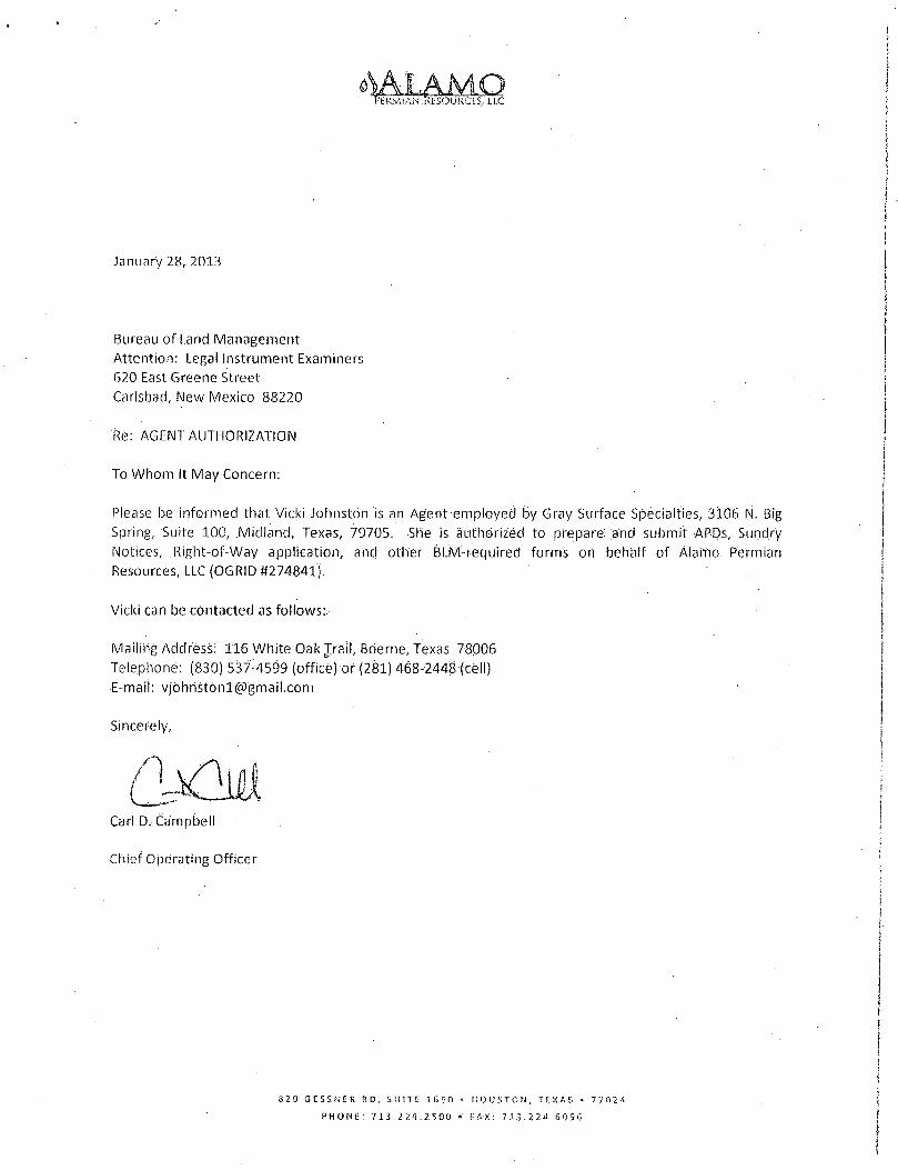
EXHIBIT C-2
^SECTION 28, TOWNSHIP 17 SOUTH, RANGE 30 EAST, N.M.P.M.^" EDDY COUNTY, STATE OF NEW MEXICO
VICINITY MAP
/ / /.( -
i. - J T~ V i
... „ L / . i>.„[y | v < . . \ \ . f
jity ^ ( V \ \ / / I
^ ~ ^ r . _ ....
~t7
7 a J A C K S ' G U N , ' ! -,. V •TVL-
jRE'VBURG • .iJlALJAttfAR \ t ^ - y
H i t \ f lSLD ;>• ' ' (
IM^SS^ f ail (X\
.^ueR[ L^Vspr'''|.Ji~^
' i i ^ ^ ^ M ";YL-"\ \ 7 ^r-^' ' ^ 1 .701 Fife--; t—' -.tsAr . ( • / »srvx i \ %
VV--.. -v ' . - I
>1.
ITS: x..
•^---t-i*- \ - -..;N~"" yrr.-—-pi;.^r
11 7 V , r.
-rt X ffOr TO SCALE
ALAMO PERMIAN RESOURCES, LLC FEDERAL S §008
LOCATED 880 FT. FROM THE SOUTH LINE AND 330 FT. FROM THE WEST LINE OF
SECTION 28, TOWNSHIP 17 SOUTH, RANGE 30 EAST, N.M.P.M.
EDDY COUNTY STATE OF NEW MEXICO
JANUARY 30, 2013
SURVEY NO. 1450A .jgfci MADRON SURVEYING, INC. CARLSBAD, NEW MEXICO ^

EXHIBIT C-3
^SECTION 28, TOWNSHIP 17 SOUTH, RANGE 30 EAST, N.M.P.M. ^ EDDY COUNTY, STATE OF NEW MEXICO
AERIAL PHOTO
N ^ r
• r ,* I
^ • ) Li,
FEDERAL S #008
fly ^ < ^ « ^ r
PROPOSED 376 LF % 1 ' / ~ ACCESS ROAD
\ * *
Iw'i"*
^1
»k*4
. f-
J^5
NOT TO SCALE AERIAL PHOTO: GOOGLE EARTH MARCH 2012
ALAMO PERMIAN RESOURCES, LLC FEDERAL S §008
LOCATED 880 FT. FROM THE SOUTH LINE AND 330 FT. FROM THE WEST LINE OF
SECTION 28, TOWNSHIP 17 SOUTH, RANGE 30 EAST, N.M.P.M.
EDDY COUNTY, STATE OF NEW MEXICO
JANUARY 30, 2013 SURVEY NO. 1450A
J f o MADRON SURVEYING, INC, CARLSBAD, NEW MEXICO ^

EXHIBIT D ONE-MILE RADIUS MAP
API #30-015-XXXXX ~B ~ o ooo 5" U 1 • 15 • o 1 7 o
03 O O
O ©
O O O
o o
o o
o o
o
o ° o
o o
o o o 20
o
o
o
o o o
o o
o o
OD O O
O OO
19
o o o
03 o o o
O o o
O o o
o
16
8
r0 31956 '04379
23780
0 cP
0 oo__ ^c34'806
o -31854—
04385
o G o 9 6 O
O O
o ©
©3 O
O
O O
Q o 8 °
OO O { <D
o © 21 -
O
O O O
O © O
o p
% ©
043o^ 6 1 3
o
5>4^49^ o ©
o
6
o
o
o
o
o 22 O O
O
O
O
o°
o
o
o
-04248-04246-
o 0 2 5 7
22183
J 0 / 21869 o
04383 ©04384
30<P14© 31643 31517 3 o 7 7 8 . 31954
319§§&373 23123. 04371
o 043J4 23392 3 0 3 4 1 04375 go 04372 T17S 26558
18531 c
« 21691 79456
o o
27
0 o *->w 1 oi-obi 22666 20147 3 1 | 7 2 o ! ©04360°
04378 l 23405 % 0 ©
22665 3 5 2 5 0
i04359 © 04?377 ©0?376l
o 35249^ o 0 3-U57—;3Q1-7CT
FEDERAL S #008 ALAMO PERMIAN RESOURCES, LLC 880' FSL & 330' FWL OGRID #274841 SEC 28 T17S R30E - EDDY COUNTY, NEW MEXICO

ALAMO PERMIAN RESOURCES, LLC ONE-MILE RADIUS 880'FSL and 330'FWL OGRID#274841 FEDERALS#008 Sec 28 T17S R30E, Eddy County, NM
v Api NUMBER NOTES . WELL NAME & NUMBER LEGAL DESCRIPTION fSECj TWS RANGE
30-015-31854 Mclntyre A East #15 330' FSL & 1625' FEL 20 17S 30E
30-015-34806 Mclntyre A East #19 675'FSL & 1120* FEL 20 17S 30E
30-015-04246 Federal X #3 330' FSL & 1650' FWL 21 17S 30E
30-015-04248 Federal X #4 . ' 330'FSL & 990'FWL 21 17S 30E
30-015-04249 Federal X #5 330' FSL & 2310' FWL 21 17S 30E
30-015-04369 Woolley Federal #1 660' FSL & 660' FWL 21 17S 30E
30-015-36135 APD expired Encore 21 Loco Com #1 830' FSL & 1235' FWL 21 17S 30E
30-015-04359 Grayburg Jackson PSU MB #1 990' FSL & 330' FWL 27 17S 30E
30-015-04360 Grayburg Jackson PSU MB #2 1650' FSL & 330' FWL 27 17S 30E
30-015-04371 Federal S # l 660' FNL & 1980' FWL 28 17S 30E
30-015-04372 Federals #2 1980' FNL & 1980' FWL 28 17S 30E
30-015-04373 Federals #3 330' FNL & 2310' FWL 28 17S 30E
30-015-04374 Federal S #4 1650' FNL & 2310' FWL 28 17S 30E
30-015-04375 P&A Federal S #5 1650' FNL & 990' FWL 28 17S 30E
30-015-04376 Grayburg Jackson WF Unit #1 990' FSL & 330' FEL 28 17S 30E
30-015-04377 Grayburg Jackson PSU ME #1M 990'FSL & 1650'FEL 28 17S 30E
30-015-04378 P&A G-J Premier Sand Unit BA #3 1650' FSL & 330'FEL 28 17S 30E
30-015-10531 Grayburg Jackson PSU MA #2 2615'FNL& 1295'FEL 28 17S 30E
30-015-20147 Federals #6 1980' FSL & 1980' FWL 28 17S 30E
30-015-21691 MA #3 (BLM Base Map OCD says API in Sec 25/16S/31E 28 17S 30E
30-015-22665 APD expired Federals #7 660* FSL & 660' FWL 28 17S 30E
30-015-22666 APD expired Federal S #8 1980' FNL & 660' FWL ' 28 17S 30E
30-015-23123 Maddren A Federal #4 330' FNL & 1650' FEL 28 17S 30E
30-015-23392 Maddren A Federal #5 1650'FNL & 2310'FEL 28 17S 30E
30-015-23405 Maddren A Federal #2 990' FSL & 1650' FWL 28 17S 30E
30-015-26558 P&A Bogart Federal Com #1 2030' FNL & 1830' FWL 28 17S 30E
30-015-30170 Grayburg Jackson PSU MA #6Z 330' FSL & 50' FEL 28 17S 30E
30-015-30341 Grayburg Jackson PSU MA #7 1305' FNL & 1305'FEL 28 17S 30E
30-015-31157 Grayburg Jackson PSU ME #3A 330'FSL& 1330' FEL 28 17S 30E
30-015-31272 Grayburg Jackson PSU MA #9 1840' FSL & 1680' FEL 28 17S 30E
30-015-35249 Cagney 28 Federal #1 660'FSL & 810' FEL 28 17S 30E
30-015-35250 Cagney 28 Federal Com #2 860' FSL & 1980' FWL . 28 17S 30E
30-015-79456 MA #10 on BLM base map; not in OCD database 28 17S 30E

ALAMO PERMIAN RESOURCES, LLC ONE-MILE RADIUS 880' FSL and 330' FWL
OGRID #274841 FEDERAL S #008 Sec 28 T17S R30E, Eddy County, NM
l ^ j p i g M B E R -%. NOTES- . „ WELL NAME & NUMBER LEGAL DESCRIPTION., , - SEC TWS RANGE
30-015-04379 Beeson B #1 on B L M base map; not in OCD database 29 17S 30E
30-015-04380 Beeson F Federal #8 330' FSL & 1650' FEL 29 17S 30E
30-015-04381 Beeson F Federal #9 330' FSL & 2310' FWL 29 17S 30E
30-015-04382 P&A Federal T # l 330'FSL& 330' FEL 29 17S 30E
30-015-04383 P&A Woolley #7-D 1650' FSL & 990' FWL 29 17S 30E
30-015-04384 P&A Arnold #9-B 1650'FSL& 1650'FEL 29 17S 30E
30-015-04385 P&A Federal K #3 330' FNL & 330' FEL 29 17S 30E
30-015-10257 P&A Fed EX #1 1980'FNL & 1980'FEL 29 17S 30E
30-015-21869 Federal K # l 1980' FSL & 990' FWL 29 17S 30E
30-015-22183 Hudson Federal #1 1990' FNL & 1970' FEL 29 17S 30E
30-015-23780 Beeson D Federal #2 1100'FNL & 2300'FWL 29 17S 30E
30-015-29841 Beeson F Federal #23 361'FSL & 2334'FEL 29 17S 30E
30-015-30014 Beeson F Federal #25 990' FSL & 1674' FEL 29 17S 30E
30-015-30778 Beeson F Federal #28 890' FSL & 2234' FEL 29 17S 30E
30-015-31517 Beeson F Federal #32 990" FSL & 1990' FWL 29 17S 30E
30-015-31518 Beeson F Federal #33 330' FSL & 1330' FWL 29 17S 30E
30-015-31643 Beeson F Federal #35 990' FSL & 890' FWL 29 17S 30E
30-015-31953 Federal S #7 330'FNL & 1809'FWL. 29 17S 30E
30-015-31954 Victoria 29 Federal #1 990'FSL& 990'FEL 29 17S 30E
30-015-31956 Pinto 29 Federal #1 330'FNL & 1980'FEL 29 17S 30E
30-015-04422 Scheurich B #6 2310' FNL & 2310' FWL 32 17S 30E
30-015-04426 P&A Tallmadge #2 2310'FNL & 2310'FEL 32 17S 30E
30-015-04427 Tallmadge #3 330' FNL & 330' FEL 32 17S 30E
30-015-04429 State #1 on BLM base map; not in OCD database 32 17S 30E
30-015-04433 P&A State B-4108 #1 660' FNL & 1980' FWL 32 17S 30E
30-015-04436 P&A Scheurich B#8 1650'FNL & 1650' FWL 32 17S 30E
30-015-04440 P&A Digneo State #1X 2250' FNL & 990' FEL 32 17S 30E
30-015-04442 Scheurich State #2 on BLM base map; not in OCD database 32 17S 30E
30-015-04447 P&A Digneo State #1 2310' FNL & 990' FEL 32 17S 30E
30-015-29513 Sand Tank 32 State Com #2 1650'FSL& 1650'FEL 32 17S 30E
30-015-04441 P&A Woolley #18D 330'FNL & 330'FWL 33 17S 30E
30-015-04443 Grayburg Jackson PSU BB#1A 330' FNL & 990' FEL 33 17S 30E
30-015-04444 P&A Beeson Federal #1 2310'FNL & 2310'FEL 33 17S 30E

ALAMO PERMIAN RESOURCES, LLC ONE-MILE RADIUS 880" FSL and 330' FWL OGRID #274841 FEDERALS#008 Sec 28 T17S R30E, Eddy County, NM
API NUMBER' NOTES, , WELL NAME & NUMBER LEGAL DESCRIPTION '„ \ SEC "TWS RANGE
30-015-22664 Federal N #2 660' FNL & 1980' FWL 33 17S 30E
30-015-25764 Beeson Federal #1Y 2160' FNL& 2160' FEL 33 17S 30E
30-015-29186 Sand Tank 33 Federal Com #1 1650' FSL & 2100' FWL 33 17S 30E
30-015-29356 Sand Tank 33 Federal Com #2 1980'FNL & 1650'FWL 33 17S 30E
30-015-31324 Grayburg Jackson PSU BB #3 870' FNL & 600' FEL 33 17S 30E
30-015-31408 Grayburg Jackson PSU BB #2 30' FNL & 2310' FEL 33 17S 30E
30-015-31468 Grayburg Jackson PSU BB#4 990' FNL & 1650' FEL 33 17S 30E
30-015-34525 Full Tank 33 Fed Com #1 990' FNL & 1980' FEL 33 17S 30E
30-015-34777 Full Tank 33 Fed Com #2S 1650' FNL & 910' FWL 33 17S 30E
30-015-35156 P&A Full Tank 33 Federal #3 760' FNL & 1910' FWL 33 17S 30E
30-015-35257 Full Tank 33 Federal #3Y 760' FNL & I960' FWL 33 17S 30E
30-015-35379 Full Tank 33 Federal #4 990'FNL & 1830'FEL 33 17S 30E

EXHIBIT 1-1
w 2-3" POLY LINES, 1-3" FROM FEDERAL S #008, 1-3" FROM FEDERAL S
#009 TO THE FEDERAL S BATTERY UNIT C
ALAMO PERMIAN RESOURCES, LLC CENTERLINE SURVEY OF A PIPELINE CROSSING
SECTION 28, TOWNSHIP 17 SOUTH, RANGE 30 EAST, N.M.P.M. EDDY COUNTY, STATE OF NEW MEXICO
JANUARY 17, 2013
SW5Z'\S"W .264i.8a_EL 21
28
22
27
STAI72+65.1 EJO.L 2 - 3 POLYS ;
STA,71+45.0 PI RIGHT ! STAi 69+87.1 4/W POWER UNE I STA,68+62.6 PI RIGHT
STAI60+77.1 CL 15' LEASE RD STA'57+72.9 PI LEFT STA |57+39.9 1/W POWER UNE STA 154+95.0 PHILLIPS BPL STAi54+67.4 PHILLIPS BPL STA 154+40.7 BPL (UNKNOWN) STA .54+23.6 BPL (UNKNOWN) STA 53+28.1 4/W POWER UNE
SEU 28 T^t7S^,\R.S0E._
B%M STA I48+1B.2 PI RIGHT STA 47+91.1 3/W POWER UNE •
STA ,30+67.4 PI LEFT STA 30+51.5 DCP BPL STA 30+33.7 DCP BPL STA 30+09.6 CL .15" LEASE RD. STA 16+57.3 PI LEFT
-STA-LHMTS- PO-RIGHT STA~12+17.2 PI LEFT STAI9+16.5 CL 15' LEASE RD. STA'9+00.0 Pt RIGHT " STA|7+47.3 LATERAL TO. .
I FEDERAL S J 0 0 9 / I BEGIN 2 - 3 " POLYS:
STAB+92.7 PI LEFT STA ,0+00 B.O.L. 1 - 3 " POLY
QO 0 1000
N89"52'51"E 2639.70 FT
28 27 1 * BC 1918
33 .34
DESCRIPTION A STRIP OF LAND 30 FEET WIDE CROSSING BUREAU OF LAND MANAGEMENT LAND IN SECTION 28 , TOWNSHIP 17 SOUTH, RANGE 30 EAST. N.M.P.M.. EDDY COUNTY. STATE C f NEW MEXICO AND BEING 15 FEET EACH SIDE OF THE FOLLOWING DESCRIBED CENTERLINE SURVEY:
BEGINNING AT A POINT WITHIN THE SW/4 S W / 4 OF SAID SECTION 2B, TOWNSHIP 17 SOUTH. • RANGE 30 EAST. N.M.P.M.', WHENCE THE SOUTHWEST CORNER OF SAID SECTION 28 , TOWNSHIP 17 SOUTH. RANGE 30 EAST, N.M.P.M. BEARS S 3 r 4 8 ' 0 8 " W , A DISTANCE OF 889.36 FEET; THENCE S7T48 '32 "E A DISTANCE.OF 392.75 FEET TO AN ANGLE POINT OF THE UNE HEREIN DESCRIBED:' . THENCE N36M5'24"E A DISTANCE OF 507 .35 FEET TO AN ANGLE POINT OF THE UNE HEREIN DESCRIBED; THENCE S56-52'03"E A DISTANCE OF 317.24 FEET TO AN ANGLE POINT OF THE UNE HEREIN DESCRIBED; THENCE S8 f f 46 ' 36 "E A DISTANCE OF .200.79 FEET TO AN ANGLE POINT OF THE UNE HEREIN DESCRIBED; THENCE S13-01'45"E A DISTANCE OF 239.51 FEET TO AN ANGLE POINT. OF THE UNE HEREIN DESCRIBED; THENCE H I S ' ^ ' Z T E . A . DISTANCE OF 1410.13 FEET TO AN ANGLE POINT OF THE UNE HEREIN DESCRIBED; THENCE N 3 f f 0 7 ' 4 8 y i A DISTANCE OF 1750.83 FEET TO AN ANGLE POINT OF THE UNE HEREIN DESCRIBED; THENCE N 0 r O 0 ' 5 3 " E A DISTANCE OF 954.75 FEET TO AN ANGLE POINT OF THE LINE HEREIN DESCRIBED: THENCE N 0 r i 4 ' 1 2 " W A DISTANCE OF 1089.78 FEET TO AN ANGLE POINT OF THE UNE HEREIN DESCRIBED; THENCE N12-41'26"E A DISTANCE OF 282.45 FEET TO AN ANGLE POINT OF THE LINE HEREIN DESCRIBED;
THENCE N59'49 '47"E A DISTANCE OF 120.09 FEET THE TERMINUS OF THIS CENTERUNE SURVEY. WHENCE THE' NORTH QUARTER CORNER OF SAID SECTION 2 8 . TOWNSHIP 17 SOUTH. RANGE 30 EAST, N.M>.M. BEARS N 4 r 2 9 ' 5 4 " E , A DISTANCE OF 716.59 FEET;
SAID STRIP OF LAND BEING 7265 .67 FEET OR 440.34 RODS IN LENGTH. CONTAINING 5.004 ACRES MORE OR LESS AND BEING ALLOCATED BY FORTIES AS FOLLOWS:
SW/4 SW/4 1077.07 L F . 65.28 RODS 0.742 ACRES S E / 4 SW/4 1547.33 L F . 93 .78 RODS 1.066 ACRES SW/4 S E / 4 867.80 L F : 52.59. RODS 0.598 ACRES NW/4 S E / 4 278.46 L F . 16.88 RODS 0.192 ACRES N E / 4 S W / 4 1322.81 L F . 80 .17 RODS 01911 ACRES S E / 4 NW/4 1320.49 L F . 80 .03 RODS 0.909 ACRES NE/4 NW/4 851.71 L.F.- 51:62 RODS 0.587 ACRES
GENERAL. NOTES 1.) THE INTENT OF THIS ROUTE SURVEY IS TO ACQUIRE AN EASEMENT.-
2.) BASIS OF BEARING IS NMSP EAST MODIFIED TO SURFACE COORDINATES.
SHEET: 1-4
MADRON SURVEYING, INC.
SURVEYOR CERTIFICATE
I. F1UM0N F. JARAMILLO.,A NEW MEXICO PROFESSIONAL SURVEYOR NO. 12797, HEREBY CERTIFY. THAT I HAVE' CONDUCTED AND AM RESPONSIBLE FOR THIS SURVEY. THAT THIS SURVEY-IS T R U E ' A N D / C O R R E C T TO THE BEST OF MY KNOWLEDGE AND BEUEF, ANDT'.THAT ;THIS SURVEY''AND^PLAT MEET THE MINIMUM STANDARDS FOR LAND SURVEYING'"IN-THE::STATE" OF^NEW'MEXICO.
+ .~Jf • " '• ' ' T . i INiWITNESS WHEREOF. THIS CERTIFICATE IS EXECUTED AT CARLSBAD,
",7£? •<*•''' NEW MEXICO.JTHIS • / A ~nAY OF JANUARY 2013
A $x' rrM FIUMON F. JAlAmiL0.rPLS:t:i27B7 >
MADRON SURVEYING. INC J O l SOUTH .CANAL . 'CARLSBAD. NEW MEXICO 88220 P h i - 3 " (575) 234-3341
SURVEY NO. 1506
CARLSBAD,. NEW MEXICO

EXHIBIT 1-2
2-3" POLY LINES, 1-3" FROM FEDERAL S §008, 1-3" FROM FEDERAL S #009 TO THE FEDERAL S BATTERY UNIT C
ALAMO PERMIAN RESOURCES, LLC CENTERLINE SURVEY OF A PIPELINE CROSSING
SECTION 28, TOWNSHIP 17 SOUTH, RANGE 30 EAST, N.M.P.M. EDDY COUNTY, STATE OF NEW MEXICO
JANUARY 17, 2013
20 21 " 1 9 8 o 1
29 28
5B9"52'0B"W 2641.19 FT
FEDERAL S 'BATTERY UM]T C
589 ,53'15°W 2641.89 FT 21 22
BC'19IB
28 27
•SEQ 28 TJ73J.R.S0E.
MAIN LINE SEE SHEET 1-
rA O+OO BEGIN LATERAL Jp31_P0LY
STA 4+32.5 'PI LEFT —r
'STA 7+47.3 MAIN UNE [BEGIN 2 - 3 " POLYS '
2 9 28 , -
52 3 3
lS^SB'QQTE . 111.62 FT
, (TIE) 2—S47-55,42*W
1431.12 FT t
N89I52''55°E 2617.49_FT N89,52'51"E 2639.70 FT
28 ,27
BC 1916 33 34
DESCRIPTION A STRIP OF LAND 30 FEET WIDE CROSSING BUREAU OF LAND MANAGEMENT LAND IN SECTION 2 8 . TOWNSHIP 17 SOUTH, RANGE 30 EAST, N.M.P.M., EDDY COUNTY. STATE OF NEW MEXICO AND.BEING 15 FEET EACH SIDE OF THE FOLLOWING DESCRIBED CENTERLINE SURVEY: ' '
BEGINNING AT A POINT WITHIN THE NW/4 SW/4 OF SAID SECTION 28 , TOWNSHIP 17 SOUTH, RANGE'30 EAST. N:M.P.M., WHENCE THE WEST QUARTER CORNER OF SAID SECTION .28 . TOWNSHIP 17 SOUTH, RANGE 30 EAST, N.M.P.M. BEARS N40 - 38 '33 'W, A DISTANCE OF 1557.31 FEET; THENCE S 0 1 W 3 4 - W A DISTANCE OF 432:48 FEET TO AN ANGLE POINT OF THE UNE HEREIN DESCRIBED; THENCE. S53*36'0U"£ A DISTANCE OF 111.82 FEET THE TERMINUS OF THIS CENTERLINE SURVEY. WHENCE THE SOUTHWEST CORNER OF SAID SECTION 28. TOWNSHIP 17 SOUTH. RANGE 3 0 EAST. N.M.P.M. BEARS S 4 r 5 5 ' 4 2 " W . A DISTANCE OF. 1431.12 FEET;
SAID STRIP OF LAND BEING 544.30 FEET OR 32.99 RODS IN LENGTH.-CONTAINING 0.37S ACRES MORE OR .LESS" AND BDNG ALLOCATED BY FORTIES AS FOLLOWS:
NW/4 SW/4 135.66 L F . 8.23 RODS 0 .094 ACRES S W / 4 SW/4 408.44 L F . 24 .75 RODS 0.281 ACRES
SURVEYOR CERTIFICATE
I. FIUM0N F. JARAMlLU). A NEW. MEXICO PROFESSIONAL SURVEYOR NO. 12797, HEREBY CERTIFY THAT I HAVE CONDUCTED AND AM RESPONSIBLE FOR THIS SURVEY. THAT THIS .SURVEY I S J R U E ' A N D CORRECT TO THE BEST OF MY KNOWLEDGE AND BEUEF. AND JHAT THIS SURVEYED PLAT MEET THE MINIMUM STANDARDS FOR LAND-SURVEYING .IN.-THE STATE OF, "NEW;MEXICO.
c-vv' ~ S'fJZ . IN/WITNESS WHEREOF. THIS CERTIFICATE IS EXECUTED AT CARLSBAD.
'DAY OF JANUARY 2013
GENERAL NOTES 1. ) THE INTENT OF THIS ROUTE SURVEY IS TO ACQUIRE .AN EASEMENT.
2. ) BASIS OF BEARING IS NMSP EAST MODIFIED TO SURFACE COORDINATES. NEW'MEXICO, THIS HI
MADRON SUWEYINC iNC 301 SOUTH CANAL CARLSBAD. NE'.V MEXICO 8B220 P h l - 3 " (575) 234-3341
, SHEET: Z-4
MADRON SURVEYING, /INC. -mmoN-r.fjiR^np^!fiz797 y • SURVEY NO. isoer
t^^'c$RLSBAD., NEW MEXICO

EXHIBIT 1-3
2-3" POLY LINES, 1-3" FROM FEDERAL S §008, 7-3" FROM FEDERAL S #009 TO THE FEDERAL S BATTERY UNIT C
ALAMO PERMIAN RESOURCES, LLC CENTERLINE SURVEY OF A PIPELINE CROSSING
SECTION 28, TOWNSHIP 17 SOUTH, RANGE 30 EAST, N.M.P.M. EDDY COUNTY, STATE OF NEW MEXICO
JANUARY 17, 2013
\ . ' ^PEDERjfi*'S^BATTERT
f ^ T-
UNIT C t STA 72+65
-7 -? > — ^ v. T 7
1 EOL 2-3"" POLYS-,., » , ' * >• —~ * »
N, i -S3
*< S f j i
v \ > V *•
>~;5*5TAJ5+44.3 ENDUSTERAL*! l $ t STA',i7+47.-3 MAIN lilNEi
* BEGIN 2*-3 POLYSI >. * 71 s?»*- -7
/ Mi
SHEET: 3-4 SURVEY NO. 1506
MADRON SURVEYING, INC. S^SfJST CARLSBAD, NEW MEXICO

EXHIBIT 1-4
2-3" POLY LINES, 1-3" FROM FEDERAL S #008, 1-3" FROM FEDERAL S #009 TO THE FEDERAL S BATTERY UNIT C
ALAMO PERMIAN RESOURCES, LLC CENTERLINE SURVEY OF A PIPELINE CROSSING
SECTION 28, TOWNSHIP 17 SOUTH, RANGE 30 EAST, N.M.P.M. EDDY COUNTY. STATE OF NEW MEXICO
JANUARY 17. 2013
y
V
IJ
o 4 &
f * • *
FEDERAL S BATTERY .'. UNIT C"
STA 72+65.-1 E.O;i; 2 - 3 " : POLYS
7— T - ^
-LATERAL FEDERAL S - V •
- ~ #008 " N :
i „ i N i i
* STA ' 0 + 0 0 : B.O.L.i'1 - 3 " POLY
STA 0 + 0 0 BEGIN LATERAL • . .1—3" POLY •
STA 5+44 3-<END LATERAL , STA 7+47 3 MAIN LINE T
BEGIN 2 - 3 " POLYS
.SHEET: 4-4
MADRON SURVEYING, INC. 301 SOUTH CAWL SURVEY NO. 1506,
CARLSBAD, NEW MEXICO
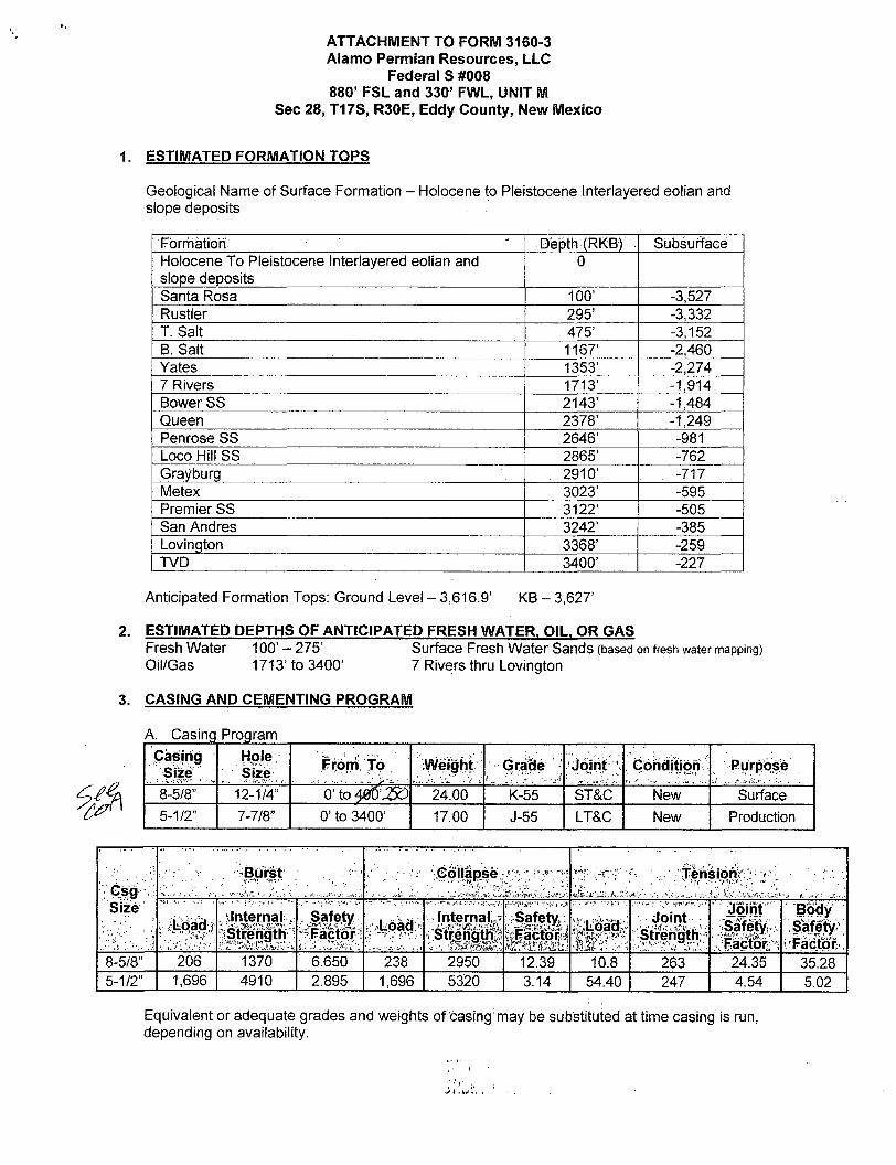
ATTACHMENT TO FORM 3160-3 Alamo Permian Resources, LLC
Federal S #008 880' FSL and 330' FWL, UNIT M
Sec 28, T17S, R30E, Eddy County, New Mexico
1. ESTIMATED FORMATION TOPS
Geological Name of Surface Formation - Holocene to Pleistocene Interlayered eolian and slope deposits
Formation ' Depth (RKB) Subsurface Holocene To Pleistocene Interlayered eolian and slope deposits
0
Santa Rosa 100' -3,527 Rustler 295' -3,332 T. Salt 475' -3,152 B. Salt 1167' -2,460 Yates 1353' -2,274 7 Rivers 1713' -1,914 Bower SS 2143' -1,484 Queen 2378' -1,249 Penrose SS 2646' -981 Loco Hill SS 2865' -762 Grayburg 2910' . -717 Metex 3023' -595 Premier SS 3122' -505 San Andres 3242' -385 Lovington 3368' -259 TVD 3400' -227
Anticipated Formation Tops: Ground Level - 3,616.9' KB - 3,627'
2. ESTIMATED DEPTHS OF ANTICIPATED FRESH WATER, OIL. OR GAS Fresh Water 100' - 275' Surface Fresh Water Sands (based on fresh water mapping) Oil/Gas 1713' to 3400' 7 Rivers thru Lovington
3. CASING AND CEMENTING PROGRAM
A. Casing Program Casing
Size Hole
' Size From To Weight Grade Joint Condition Purpose
8-5/8" 12-1/4" 0' to 40O' 5£) 24.00 K-55 ST&C New Surface 5-1/2" 7-7/8" 0' to 3400' 17.00 J-55 LT&C New Production
!; Gsg Size
Burst ; ..- . ,•:'.;• Collapse. : ~ • -f-. • •' tensiqiV; ; ' • r !; Gsg
Size iLpad •
. Internal • Strength
Safety Factor: . Load: : Internals Safety;
bFactolfsj ;SLoao#
<m& Joint
Strength
Joint * Safety; Factor
Body Safety Factor
8-5/8" 206 1370 6.650 238 2950 12.39 10.8 263 24.35 35.28 5-1/2" 1,696 4910 2.895 1,696 5320 3.14 54.40 247 4.54 5.02
Equivalent or adequate grades and weights of casing may be substituted at time casing is run, depending on availability.

Attachment to Form 3160-3 ALAMO PERMIAN RESOURCES, LLC
Federal S #008 Page 2 of 5
SURFACE CASING: Tension Calculated using weight of casing times landing depth without utilizing
buoyancy effects Collapse Calculated with full internal evacuation and a collapse force equal to the
mud gradient in which the casing will be run. The effects of axial load on collapse will be considered.
Burst In all cases a conservative fracture pressure will be used such that it represents the upper limit of potential fracture gradients up to a 1.0 psi/ft. gradient. The effects of tension on burst will not be utilized.
PRODUCTION CASING: Tension Calculated using weight of casing times landing depth without utilizing
buoyancy effects. Collapse Calculated with full internal evacuation and a collapse force equal to the
mud gradient in which the casing will be run. The effects of axial load on collapse will be considered.
Burst Maximum surface treating pressure will be limited to 70% of the rated burst pressure.
B. Cement Program The cement volumes are estimates and will be adjusted based on the volume based on the open hole volume determined by logging -
Casing String Interval TOC
Cement Type / Class
Description Cement Req-d for % Excess
Surface Oto 400' <L3o
Surface C
Lead: 150 sx "C" Lite + 1/4 pps celloflake
13.0 ppg, 1.89 cuft/sx Tail: 150 sx "C" + 2% CaCI
14.8 ppg,1.32 cuft/sx
130% over Theoretical Volumes
Production Oto 3400' Surface C
Lead: 320 sx 35/65 "Poz/C + 6% gel + 5 #/sx Salt + 6% STE + 3/10% C-45 + 2/10% C-41P + 1/4
ppg celloflake 12.5 ppg, 2.17 cuft/sx
Tail: 320 sx Class "C w/2% CaCI
14.8 ppg, 1.32 cuft/sx
70% over Theoretical Volumes
CEMENTING PROCEDURES: Casing will be cemented by the "Pump and Plug" method. A bottom plug will be utilized to help isolate the cement from contamination by the mud fluid being displaced ahead of the cement slurry. A top plug will be used to reduce contamination of cement by displacement fluid. The surface casing shall be cemented back to surface either during the primary cement job or by remedial cementing. All waiting on cement times shall be adequate to achieve a minimum of 500 psi compressive strength at the casing shoe prior to drilling out, or a minimum of 18 hrs, whichever is greater. CASING TESTING: All casing strings below the conductor shall be pressure tested to 0.22 psi per foot of casing string length or 1500 psi, whichever is greater, but not to exceed 70 percent of the minimum internal yield. SHOE TESTING. If pressure declines more than 10 percent in 30 minutes, the cement job shall be deemed unacceptable, and corrective action taken. All of the above- described tests will be recorded in the drilling log.

Attachment to Form 3160-3 ALAMO PERMIAN RESOURCES, LLC
Federal S #008 Page 3 of 5
4. PRESSURE CONTROL EQUIPMENT
A. Blowout Preventer (BOP) - Exhibit E-1 A BOP and related equipment (BOPE) will be installed, used, maintained, and tested in a manner necessary to assure well control and shall be in place and operational prior to drilling the surface casing shoe. The anticipated surface pressure, assuming a fully evacuated hole with a pressure gradient of 0.52 psi/ft. at a TD of 3400 is 1768 psi. This is well within the capabilities of the 3K system proposed to be used. All BOP and BOPE shall comply with well control requirements as stated in Onshore Oil & Gas Order No. 2. That system consists of:
- Rotating Head - 3K 11" BOP installed on the 8-5/8" surface casing - kill line (2" minimum) - 1 kill line valve (2" minimum) - 1 choke line valve - 2 chokes (refer to diagram in Exhibit E-1) - Upper kelly cock valve with handle available on drill floor - Safety valve and subs to fit all drill strings in use - Pressure gauge on choke manifold - 2" minimum choke lines - Fill-up line above the uppermost preventer.
B. Choke Manifold Equipment - Exhibit E-2 a. All choke lines shall be straight lines unless turns use tee blocks or are targeted with
running teed, and shall be anchored to prevent whip and reduce vibration. b. Choke manifold equipment configuration shall be as indicated on the example diagram
shown in Exhibit E-2. c. All valves (except chokes) in the kill line choke manifold, and choke line are a type that
does not restrict the flow (full opening) and that allows a straight through flow. d. Pressure gauges in the well control system are a type designed for drilling fluid service. e. The 3K system accumulator has sufficient capacity to close all BOP's and retain 200 psi
above precharge, using nitrogen bottles that meet manufacturer's specifications. f. A precharge pressure test will be conducted prior to connecting the closing unit to the
BOP stack. The accumulator pressure will be adjusted with nitrogen gas to be within the operating limits as shown Pressure Operating Precharge Pressure rating.
Pressure Rating
Operating Pressure
Precharge Pressure Pressure Rating
Operating Pressure Desired Maximum Minimum
1,500 psi 1,500 psi 750 psi 800 psi 700 psi 2,000 psi 2,000 psi 1,000 psi 1,100 psi 900 psi 3,000 psi 3,000 psi 1,000 psi 1,100 psi 900 psi
g. Power for the closing unit pumps shall be available to the unit at all times so that the pumps shall automatically start when the closing valve manifold pressure has decreased to the pre-set level.
h. The BOP closing unit shall be equipped with sufficient number and sizes of pumps so that, with the accumulator system isolated from service, the pumps shall be capable of opening the hydraulically-operated gate valve plus closing the annular preventer on the smallest size drill pipe to be used within 2 minutes, and obtain a minimum of 200 psi above specified accumulator precharge pressure.
i. A manual locking device (i.e., hand wheels) or automatic locking devices shall be installed. A valve is installed in the closing line as close as possible to the annular preventer to act as a locking device. This valve will be maintained in the open position and shall be closed only when the power source for the accumulator system is inoperative.

Attachment to Form 3160-3 ALAMO PERMIAN RESOURCES, LLC
Federal S #008 Page 4 of 5
C. Tests and Testing Schedule a. The annular preventer shall be tested to 50 percent of rated working pressure. Pressure
shall be maintained at least 10 minutes or until provisions of test are met, whichever is longer. This test shall be performed:
i. when initially installed: ii. whenever any seal subject to test pressure is broken: iii. following related repairs: and iv. at 30-day intervals.
b. Valves shall be tested from working pressure side during BOPE tests with all downstream valves open.
c. When testing the kill line valve(s), the check valve shall be held open or the ball removed. d. Annular preventers shall be functionally operated at least weekly. e. A BOPE pit level drill shall be conducted weekly for each drilling crew. f. Pressure tests shall apply to all related well control equipment. g. All of the above described tests and/or drills shall be recorded in the drilling log.
See Exhibits E-1 - E-2.
MUD PROGRAM
Drilling Interval Fluid Type Weight Description
0 to 40t)L Fresh Water 8.6 to 9.2 ppg 32-34 Vis FL no Control Gel/Lime Circ Steel Pits Closed loop Cutting Via Backhoe to rolloff
Oto 1700' Cdt Brine Water /
9.6 to 10.1 ppg
29-32 Vis no Control MF-55 for Solids and MF -55 & paper sweeps Circ Steel Pits Closed loop Cutting Via Backhoe to rolloff
1700' to 3200' Cut Brine Water 9.6 to 10.1 ppg
Lower FL w/ starch <16 add SW gel -32-36 Vis no Control MF-55 for Solids and MF -55 & paper sweeps Circ Steel Pits Closed loop Cutting Via Backhoe to rolloff
Mud additions will be coordinated through contract representative. This program is only a guide, and hole conditions will dictate mud system requirements and changes. Sufficient mud materials will be kept on location at all times in order to combat lost circulation, or unexpected kicks. In order to run open-hole logs and casing, the viscosity and water loss may have to be adjusted to meet these needs.
The mud program and related drilling procedures as proposed is designed to prevent the loss of well control and produce a borehole ready to receive casing and allow efficacious cementing of the casing. This will be accomplished by: o Mud monitoring equipment shall be in place to visually detect volume changes
indicating loss or gain of circulating fluid volume, o Testing and Record Keeping
• Slow pump speed will be recorded on daily drilling report after mudding up. • A mud test shall be performed at least every 24 hours after mudding up to
determine density, viscosity, gel- strength, filtration, and pH. • These will be recorded on daily drilling report every time they are taken,
o Gas detecting equipment shall be installed in the mud return system, and hydrocarbon gas shall be monitored for pore pressure changes.

Attachment to Form 3160-3 ALAMO PERMIAN RESOURCES, LLC
Federal S #008 Page 5 of 5
TECHNICAL STAGES OF OPERATION
A. Testing: None planned. B. Logging:
o Mud logging - Base of Surface Casing to TD o Based on the Borehole conditions Open Hole Logging is planned
i. TD thru Pay - Gamma Ray Neutron Density Laterolog ii. TD thru Surface - Gamma Ray/Neutron
C. Conventional Coring: None anticipated. D. Directional Drilling: No directional drilling is anticipated.
ANTICIPATED RESERVOIR CONDITIONS
No abnormal temperatures or pressures are anticipated. In the event abnormal pressures are encountered, the proposed mud program will be modified to increase the mud weight. The estimated evacuated BHP = 1768 psi with a temperature of 80 degrees F. Low levels of H2S have been monitored in producing wells in the area, so H2S may be present while drilling the well. An H2S Plan and H2S Rig Layout (Exhibit G) are attached to the Drilling Program.
OTHER PERTINENT INFORMATION
A. Auxiliary Equipment o Upper and lower Kelly cocks. Full opening stab in valve on the rig floor.
B. Anticipated Starting Date o Anticipated starting date: Immediately upon approval. o Anticipated completion of drilling operations: Approximately 3 Weeks after spud date.

Exhibit E-l - BOP Diagram Alamo Permian Resources Federal S #008 Dual Ram BOP 3000 PSI WP
I
e Manifold Minimum
Adapter
8-5/8" Casing

Exhibit E-2 - Choke Manifold Alamo Permian Resources Federal S #008 Green Energy Remotely Operated Adjustable Choke
3000 PSI WP
Remotely Operated Adjustable
Choke
Choke Isolation
Buffer Tank
4" Nominal i _ Choke Line X-
Sequence Optional
Manual Adjustable
Choke Choke
isolation Valve
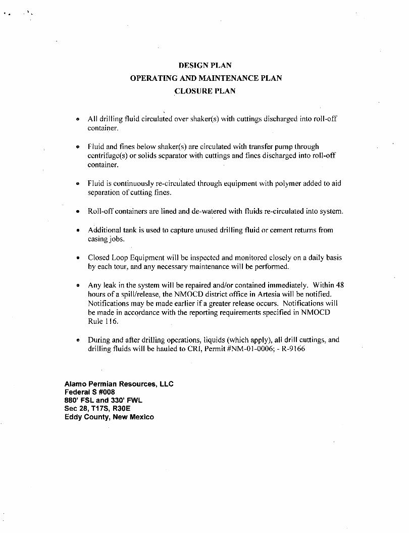
DESIGN PLAN
OPERATING AND MAINTENANCE PLAN
CLOSURE PLAN
o All drilling fluid circulated over shaker(s) with cuttings discharged into roll-off container.
• Fluid and fines below shaker(s) are circulated with transfer pump through centrifuge(s) or solids separator with cuttings and fines discharged into roll-off container.
» Fluid is continuously re-circulated through equipment with polymer added to aid separation of cutting fines.
• Roll-off containers are lined and de-watered with fluids re-circulated into system.
• Additional tank is used to capture unused drilling fluid or cement returns from casing jobs.
• Closed Loop Equipment will be inspected and monitored closely on a daily basis by each tour, and any necessary maintenance will be performed.
» Any leak in the system will be repaired and/or contained immediately. Within 48 hours ofa spill/release, the NMOCD district office in Artesia will be notified. Notifications may be made earlier if a greater release occurs. Notifications will be made in accordance with the reporting requirements specified in NMOCD Rule 116.
• During and after drilling operations, liquids (which apply), all drill cuttings, and drilling fluids will be hauled to CRJ, Permit #NM-01-0006; - R-9166
Alamo Permian Resources, LLC Federal S #008 880' FSL and 330' FWL Sec 28, T17S, R30E Eddy County, New Mexico

Exhibit F - Drilling Rig Layout
260'
O
North
130'
a. 2
•
Mud 14' 24' I
Mud Pu 14' 24'
7'-6" Wide
Frac Tank 10'-8" Wid : x 40' Long
SW - Wind Direction
a. CO
§ o I «
a x \8°
o o
• cn 8-gS tj) . to 3 fe ci > in x
Tool House 9'-8" Wide x 30' Long
Pi tip #2 • V fide
ing
np#2 Vide L ing
Generator House 8' Wide x 40'-6" Long
Diesel Tank 9'-8" Wide x 30' Lone
Mud M xing Pit < 4Z Long
o
260'
Alamo Permian Resources Drilling Rig Layout Federal S #008 880' FSL & 330' FWL, Section 28 T-17-S, R-30-E Unit Letter M Eddy County, New Mexico
Overall Pad Dimension: 260' x 270' Topsoil to be Stockpiled on the West side of location V-door faces North Prevailing Wind Direction : SW

ALAMO PERMIAN RESOURCES, L L C
HYDROGEN SULFIDE (H2S) CONTINGENCY PLAN FOR DRILLING / COMPLETING / WORKOVER / FACILITY WITH THE EXPECTATION OF H2S IN EXCESS OF 100 PPM
ALAMO PERMIAN RESOURCES, LLC NEW DRILL WELLS:
Federal S #008 880' FSL and 330' FWL, Unit M
Sec 28, T17S, R30E Eddy County, New Mexico
Federal S #009 1650' FSL and 985' FWL, Unit L
Sec 28, T17S, R30E Eddy County, New Mexico
This well/facility is not expected to have H2S, but the following is submitted as requested.
1

TABLE OF CONTENTS
I . General Emergency Plan Page 3
n. Emergency Procedures for Uncontrolled Release of H2S Page 3
in. Emergency Call List Page 3
IV. Emergency Response Numbers Page 4
v. Protection of the General (ROE) Radius of Exposure Page 5
Vi. Public Evacuation Plan Page 5
VII. Procedure for Igniting an Uncontrollable Condition Page 6
VIII. Required Emergency Equipment Page 6
IX Using Self-Contained Breathing Air Equipment (SCBA) Page 7
X Rescue & First Aid for Victims of H2S Poisoning Page 7
XI. H2S Toxic Effects Page 8
XII. H2S Physical Properties Page 9
XIII Location Map Page 10
XIV. Vicinity Map Page 12.
2

GENERAL H2S EMERGENCY ACTIONS
In the event of any evidence of H2S emergency, the following plan will be initiated:
1. All personnel will immediately evacuate to an upwind and if possible uphill "safe area."
2. If for any reason a person must enter the hazardous area, they must wear a SCBA (self-contained breathing apparatus).
3. Always use the "buddy system." 4. Isolate the well/problem if possible. 5. Account for all personnel. 6. Display the proper colors warning all unsuspecting personnel of the danger at
hand. 7. Contact the company representative as soon as possible if not at the location (use
the enclosed call list as instructed).
At this point the company representative will evaluate the situation and coordinate the necessary duties to bring the situation under control, and if necessary, the notification of emergency response agencies and residents.
EMERGENCY PROCEDURES FOR AN UNCONTROLLABLE RELEASE OF H2S
1. All personnel will don the self-contained breathing apparatus. 2. Remove all personnel to the "safe area" (always use the "buddy system"). 3. Contact company representative if not on location. 4. Set in motion the steps to protect and/or remove the general public to any
upwind "safe area." Maintain strict security and safety procedures while dealing with the source.
5. No entry to any unauthorized personnel. 6. Notify the appropriate agencies: City Police - City streets
State Police - State Roads County Sheriff - County Roads
7. Call the NMOCD.
If at this time the supervising person determines the release of H2S cannot be contained to the site location and the general public is in harm's way, he will immediately notify public safety personnel.
EMERGENCY CALL LIST
Office Steven Masten (432) 897-•0673 Michael Stewart (432) 682-•1122 Pat Seale (432) 897-•0673 Tony Pelletier (832) 657-•8002
Alamo Office-Houston (713) 224-•2500 Alamo Office-Midland (432) 897-•0673
Cell (432) 557-5847 (432) 638-9009 (713)899-1712 (281)413-4578
Operations Manager Drilling Engineer Sr. VP/Operations President/CEO
3

EMERGENCY RESPONSE NUMBERS Eddy County, New Mexico
State Police - Carlsbad 575-885-3137 City Police - Carlsbad 575-885-2111 State & City Police - Artesia 575-746-2703
Eddy County Sheriff - Carlsbad 575-887-7551
Fire Department - Carlsbad 575-887-3798 Fire Department - Artesia 575-746-2701
Local Emergency Planning - Carlsbad 575-887-6544 Local Emergency Planning - Artesia 575-746-2122
New Mexico Oil Conservation Division - Carlsbad 575-748-1283 Randy Dade - OCD District Supervisor-Carlsbad 575-626-1372 (cell)
Bureau of Land Management - Carlsbad 575-234-5972
State Emergency Response Center (SERC) - Santa Fe 505-476-9600 24 hour 505-827-9126
N M State Emergency Operations Center 505-476-9635 National Emergency Response Center (Washington DC) 800-424-8802
Other: Boots & Coots IWD 800-256-9688 or 281-934-8884 Cudd Pressure Control 432-699-0139 or 432-563-3356 Halliburton 575-746-2757 BJ Services 575-746-3569 Flight for Life - 4000 24 th St, Lubbock, Texas , 806-746-9911 Aerocare - R3, Box 49F, Lubbock, Texas . 806-747-8923 Med Flight Air Ambulance - 2301 Yale Blvd., Albuq, NM 505-842-4433 SB Aid Med Serv - 2505 Clark Carr Loop SE, Albuq, NM 505-842-4949
<• 4

PROTECTION OF THE GENERAL (ROE) RADIUS OF EXPOSURE
In the event greater than 100 ppm H2S is present, the ROE calculations will be done to determine if the following conditions exist and whether the Plan must be activated:
* 100 ppm at any public area (any place not associated with this site)
* 500 ppm at any public road (any road which the general public may travel).
* 100 ppm radius of 3000' will be assumed if there is insufficient data to do the calculations, and there is a reasonable expectation that KL2S could be present in concentrations greater than 100 ppm in the gas mixture.
Calculation for the 100 ppm ROE: (H2S concentrations in decimal form)
ROE - [(1.589)(H2S concentration)(Q)] (A0.6258) 10,000 ppm + = .01 1,000 ppm+ = .001
Calculation for the 500 ppm ROE: 100 ppm + = 0001 10 ppm + = .00001
ROE = [(0.4546)(H2S concentration)(Q)] (^.6258)
EXAMPLE: I f a well/facility has been determined to.have 650 ppm H2S in the gas mixture and the well/facility is producing ai a gas rate of 200 MCFD then:
ROE for 100 ppm ROE=[(1.589)(.00065)(200,000)] A0.6258 ROE=28.1'
ROE for 500 ppm ROE=[(.4546)(.00065)(200,000)] A0.6258 ROE=12.8'
These calculations will be forwarded to the appropriate NMOCD district office when applicable.
PUBLIC EVACUATION PLAN
When the supervisor has determined that the general public will be involved, the following plan will be implemented.
1. Notification of the emergency response agencies of the hazardous condition and implement evacuation procedures.
2. A trained person in H2S safety shall monitor with detection equipment the H2S concentration, wind and area of exposure. This person will determine the outer perimeter of the hazardous area. The extent of the evacuation area will be determined from the data being collected. Monitoring shall continue until the situation has been resolved. All monitoring equipment shall be UL approved for use in Class I Groups A, B, C & D, Division I hazardous locations. All monitors will have a minimum capability of measuring H2S, oxygen, and flammable values.
3. Law enforcement shall be notified to set up necessary barriers and maintain such for the duration of the situation as well as aid in the evacuation procedure.
4. The company representative shall stay in communication with all agencies throughout the duration of the situation and inform such agencies when the situation has been contained and the affected area is safe to enter.
5

PROCEDURE FOR IGNITING AN UNCONTROLLABLE CONDITION
The decision to ignite a well should be a last resort with one, i f not both, of the following conditions:
1. Human life and/or property are endangered. 2. There is no hope of bringing the situation under control with the prevailing
conditions at the site.
Instructions for Igniting the Well:
1. Two people are required. They must be equipped with positive pressure, self-contained breathing apparatus and "D"-ring style, full body, OSHA approved safety harness. Non-flammable rope will be attached.
2. One of the people will be a qualified safety person who will test the atmosphere for H2S, oxygen and LFL. The other person will be the designated company representative.
3. Ignite upwind from a distance no closer than necessary. Make sure that the ignition site has the maximum escape avenue available. A 25 mm flare gun with a range of approximately +/- 500 feet shall be used to ignite the gas.
4. Before igniting, check for the presence of combustible gases. 5. After igniting, continue emergency actions and procedures as before.
REQUIRED E M E R G E N C Y EQUIPMENT
1. Breathing Apparatus » Rescue Packs (SCBA) - 1 unit shall be placed at each breathing area, 2 shall be stored in
the safety trailer. 9 Work / Escape Packs - 4 packs shall be stored on the rig floor with sufficient air hose not
to restrict work activity, o Emergency Escape Packs - 4 packs shall be stored in the doghouse for emergency
evacuation.
2. Signage and Flagging • One Color Code Condition Sign will be placed at the entrance to the site reflecting the
possible conditions at the site. » A Colored Condition flag will be on display reflecting the condition at the site at that
time.
3. Briefing Area » Two perpendicular areas will be designated by signs and readily accessible.
4. Windsocks » Two windsocks will be placed in strategic locations, visible from all angles.
5. H2S Detectors and Alarms « The stationary detector with three (3) sensors will be placed in the upper dog house i f
equipped, set to visually alarm @ 10 ppm and audible alarm @ 15 ppm. Calibrate a

minimum of every 30 days or as needed. The three sensors will be placed in the following places: (Gas sample tubes will be stored in the safety trailer): o Rig Floor o Bell Nipple o End of flow line or where well bore fluid is being discharged
6. Auxiliary Rescue Equipment * Stretcher • Two OSELA full body harnesses o 100' of 5/8" OSHA approved rope o One 20 lb. Class ABC fire extinguisher « Communication via cell phones on location and vehicles on location
USING SELF-CONTAINED BREATHING AIR EQUIPMENT (SCBA)
1. SCBA should be worn when any ofthe following are performed: • Working near the top or on top of a tank • Disconnecting any line where H2S can reasonably be expected. • Sampling air in the area to determine i f toxic concentrations of H2S exist. • Working in areas where over 10 ppm of H2S has been detected. » At any time there is a doubt of the level of H2S in the area.
2. All personnel shall be trained in the use of SCBA prior to working in a potentially hazardous location.
3. Facial hair and standard eyeglasses are not allowed with SCBA. 4. Contact lenses are never allowed with SCBA. 5. When breaking out any line where H2S can reasonably be expected. 6. After each use, the SCBA unit shall be cleaned, disinfected, serviced and inspected. 7. All SCBA shall be inspected monthly.
R E S C U E & FIRST AID FOR VICTIMS OF H2S POISONING
« Do not panic. « Remain calm and think. • Put on the breathing apparatus. o Remove the victim to the safe breathing area as quickly as possible, upwind and uphill
from source or crosswind to achieve upwind. • Notify emergency response personnel. • Provide artificial respiration and/or CPR as necessary. o Remove all contaminated clothing to avoid further exposure. o A minimum of two (2) personnel on location shall be trained in CPR and First Aid.
7

TOXIC EFFECTS OF H2S POISONING
Hydrogen Sulfide is extremely toxic. The acceptable ceiling concentration for eight-hour exposure is 10 PPM, which is .001% by volume. Hydrogen Sulfide is heavier than air (specific gravity-1.192) and is colorless and transparent. Hydrogen Sulfide is almost as toxic as Hydrogen Cyanide and is 5-6 times more toxic that Carbon Monoxide. Occupational exposure limits for Hydrogen sulfide and other gasses are compared below in Table 1. Toxicity table for H2S and physical effects are shown in Table n.
Table 1 Permissible Exposure Limits of Various Gasses
Hydrogen Cyanide HCN .94 4.7 ppm C Hydrogen Sulfide H2S 1.192 10 ppm 15 ppm Sulfide Dioxide S02 2.21 2 ppm 5 ppm Chlorine CL 2.45 .5 ppm 1 ppm Carbon Monoxide CO .97 25 ppm 200 ppm Carbon Dioxide C02 1.52 5000 ppm 30,000 ppm Methane CH4 .55 4.7% LEL 14%UEL
Definitions A. TLV - Threshold Limit Value is the concentration employees may be exposed to based
on a TWA (time weighted average) for eight (8) hours in one day for 40 hours in one (1) week. This is set by ACGLH (American Conference of Governmental Hygienists and regulated by OSHA.
B. STEL - Short Term Exposure Limit is the 15 minute average concentration an employee may be exposed to providing that the highest exposure never exceeds the OEL (Occupational Exposure Limit). The OEL for H2S is 19 PPM.
C. IDLH - Immediately Dangerous to Life and Health is the concentration that has been determined by the ACGIH to cause serious health problems or death if exposed to this level. The IDLH for H2S is 100 PPM.
D. TWA - Time Weighted Average is the average concentration of any chemical or gas for an eight (8) hour period. This is the concentration that any employee may be exposed to based on an TWA.
TABLEH Toxicity Table of H2S
^ P e r a i j t l ^ ^ .0001 1 Can smell less than 1 ppm. .001 10 TLV for 8 hours of exposure .0015 15 STEL for 15 minutes of exposure
.01 100 Immediately Dangerous to Life & Health. Kills sense of smell in 3 to 5 minutes.
.02 200 Kills sense of smell quickly, may burn eyes and throat.
.05 500 Dizziness, cessation of breathing begins in a few minutes.
.07 700 Unconscious quickly, death will result i f not rescued promptly.
.10 1000 Death will result unless rescued promptly. Artificial resuscitation may be necessary.
8

PHYSICAL PROPERTIES OF H2S
The properties of all gases are usually described in the context of seven major categories:
COLOR ODOR VAPOR DENSITY EXPLOSIVE LIMITS FLAMMABILITY SOLUBILITY (IN WATER) BOILING POINT
Hydrogen Sulfide is no exception. Information from these categories should be considered in order to provide a fairly complete picture of the properties of the gas.
COLOR - TRANSPARENT Hydrogen Sulfide is colorless so it is invisible. This fact simply means that you can't rely on your eyes to detect its presence, a fact that makes the gas extremely dangerous to be around.
ODOR - ROTTEN EGGS Hydrogen Sulfide has a distinctive offensive smell, similar to "rotten eggs." For this reason it earned its common name "sour gas." However, H2S, even in low concentrations, is so toxic that it attacks and quickly impairs a victim's sense of smell, so it could be fatal to rely on your nose as a detection device.
VAPOR DENSITY - SPECIFIC GRAVITY OF 1.192 Hydrogen Sulfide is heavier than air so it tends to settle in low-lying areas like pits, cellars or tanks. I f you find yourself in a location where H2S is known to exist, protect yourself Whenever possible, work in an area upwind and keep to higher ground.
EXPLOSIVE LIMITS - 4.3% TO 46% Mixed with the right proportion of air or oxygen, H2S will ignite and burn or explode, producing another alarming element of danger besides poisoning.
FLAMMABILITY Hydrogen Sulfide will burn readily with a distinctive clear blue flame, producing Sulfur Dioxide (S02), another hazardous gas that irritates the eyes and lungs.
SOLUBILITY - 4 TO 1 RATIO WITH WATER Hydrogen Sulfide can be dissolved in liquids, which means that it can be present in any container or vessel used to carry or hold well fluids including oil, water, emulsion and sludge. The solubility of H2S is dependent on temperature and pressure, but if conditions are right, simply agitating a fluid containing H2S may release the gas into the air.
BOILING POINT - (-76 degrees Fahrenheit) Liquefied Hydrogen Sulfide boils at a very low temperature, so it is usually found as a gas.
9

LOCATION MAP - FEDERAL S #008
3T SECTION 28, TOWNSHIP 17 SOUTH, RANGE- 30 EAST. N. M. P.M. ~% EDDY COUNTY, STATE OF NEW MEXICO
LOCATION VERIFICATION MAP
V $ «_ \ \ i l > I— PR p0 ED 76 I f
v. ,7 ^
V.4
USGS QUAD MAI LOCO HILLS r
ALAMO PERMIAN RESOURCES, LLC FEDERAL S #008
LOCATED 880 FT. FROM THE SOUTH LINE AND 330 FT.. FROM THE WEST LINE OF
SECTION 28. TOWNSHIP 17 SOUTH. RANGE .30 EAST. N.M.P.M.
EDDY COUNTY. STATE OF NEW MEXICO
JANUARY "30. 201.3
SURVEY NO. 1450A, MADRON SURVEYING, INC. '?vȣi"':iL CARLSBAD, NEW MEXICO
10

VICINITY MAP - F E D E R A L S #008
SECTION 28, TOWNSHIP 17 SOUTH, RANGE 30 EAST, N.M.P.M. EDDY COUNTY, STATE OF NEW MEXICO
VICINITY MAP
""La
V TX'
"Vr! t.
p - \ -
-r f r
NOT TO SCALE
ALAMO PERMIAN RESOURCES. LLC FEDERAL S §008
LOCATED 880 FT. FROM THE SOUTH UNE AND 330 FT. FROM THE WEST LINE OF
SECTION.28. TOWNSHIP 17 SOUTH. RANCE 30 EAST, N.M.P.M.
EDDY COUNTY, STATE OF NEW MEXICO
JANUARY 30, 2013
SURVEY NO. VI50Ar
MADRON SURVEYING, INC. ^ S - S f CARLSBAD, NEW MEXICO ^
11

LOCATION MAP - F E D E R A L S #009
SECTION 28, TOWNSHIP 17 SOUTH, RANGE 30 EAST, N.M.P.M. EDDY COUNTY, STATE OF NEW MEXICO
LOCATION VERIFICATION MAP
"L9
j ^ ' 2 Q 'V
.? v.- / ! * •'
3*6 V j . . j V " / f x ' '
7'"'nr r^iMRAC-£f009
^ r:"Y £ \ X,No- 64 33?w' 4 ^ fcd/ V ' I "« - » -
I S^V^ACCESS, KOAfc. j | . 1 i *4 V._»l i,-/>< 26 45"W £_/i«c ^
W-V.Vs's _ ; J»V } ~~"
x?iV^J- . # i -Xv^Vj
/
USGS QUAD MAP: I.OCO HILLS
NOT TO SCAM;
.i4M#0 PERMIAN RESOURCES, LLC FEDERAL S #009
LOCATED 1650 FT. FROM THE SOUTH LINE AND 985 FT. FROM THE WEST LINE OF
SECTION 28, TOWNSHIP 17 SOUTH, RANCE 30 EAST, N.M.P.M.
EDDY COUNTY. STATE OF NEW MEXICO
JANUARY 30, 2013
' SURVEY NO. 1433A MADRON SURVEYING, INC. 'g^JT-Slf CARLSBAD, NEW MEXICO d
12

VICINITY MAP - F E D E R A L S #009
NOT TO SCALE
ALAMO PERMIAN RESOURCES, LLC FEDERAL S #009
LOCATED 1650 FT. FROM THE SOUTH LINE AND 985 FT. FROM THE WEST LINE OF
SECTION 28, TOWNSHIP 17 SOUTH, RANGE 30 EAST, N.M.P.M.
EDDY COUNTY. STATE OF NEW MEXICO
JANUARY 30. 2013
SURVEY NO. J493A MADRON SURVEYING, INC. %£f££? CARLSBAD, NEW MEXICO rJ
13

Exhibit G - H2S Rig Layout Date : June 3, 2013 Draftsman : H. Lamb
260'
260'
Legend PE - Primary Egress SE - Secondary Egress W - Wind Direction F - Flare PB - Primary Briefing Area OB - Other Briefing Area S - H2S Warning Signage WS - Wind Sock Prevailing Wind Direction - SW
OB
Alamo Permian Resources H2S Rig Layout Federal S #008 880' FSL & 330' FWL, Section 28 T-17-S, R-30-E Unit Letter M Eddy County, New Mexico

Exhibit H - Interim Reclamation Diagram
Area for Interim Remediation
260'
Alamo Permian Resources Interim Reclamation Diagram Federal S #008 880' FSL & 330' FWL, Section 28 T-17-S, R-30-E Unit Letter M Eddy County, New Mexico

ALAMO PERMIAN RESOURCES, L L C SURFACE USE AND OPERATIONS PLAN
FederalS #008 880' FSL & 330' FWL
Sec 28, T17S, R30E Eddy County, New Mexico
This plan is submitted with Form 3160-3, Application for Permit to Drill, covering the above-described well. The purpose of this plan is to describe the location of the proposed well, the proposed construction activities and operations plan, the magnitude of the surface disturbance involved, and the procedures to be followed in rehabilitating the surface after completion of the operations so that a complete appraisal can be made of the environmental effect associated with the operations.
1. EXISTING AND PLANNED ROADS EXISTING ROADS: a. The well site and elevation plat for the proposed well are reflected on Form C-102: Well
Location and Acreage Dedication Plat. The well was staked by Frank Jaramillo of Madron Surveying, Inc. Tanner Nygren, BLM Natural Resource Specialist, provided guidance and assistance with determining acceptable ingress/egress.
b. Exhibit C-l—C-3 is a portion of a topo map and an aerial map showing the proposed well site and roads in the vicinity of the proposed location. Access to the well site will be via existing 20' caliche road from CR 217 to a 12' caliche road in the NW/4 SW/4 Section 28, Township 17S, Range 30E.
c. Exhibit B-2—B-6 is a portion of a section plat showing the existing roadway that will be used to access the lease from County Road 217 (Hagerman Cutoff). The existing 12' caliche road in the SW/4 Section 28, Township 17S, Range 30E, will not be widened due to archaeology. Alamo Permian Resources, LLC, will submit a Form SF-299 to request Right of Way using this proposed route.
d. Routine grading and maintenance of existing roads will be conducted as necessary to maintain their condition as long as any operations continue on this lease.
DIRECTIONS: From the intersection of U.S. Highway 82 and Co. Rd. 217 (Hagerman Cutoff), go south on County Road 217 approximately 0.4 miles to the middle of curve that curves right. Turn left (southeast) on lease road southeast of curve. Go approximately 0.8 miles to a pump jack on right. Turn right (south) on road to pumpjack at southwest corner of pad follow lease road approximately 0.4 miles to road with red and white ribbon on right side (west) of road. Location is approximately 400'. PLANNED ACCESS ROAD: Exhibit B-1 is a portion of a section map showing a proposed temporary access road approximately 376', from existing 12' caliche lease road to the southeast corner of the well pad. a. The maximum width of the ninning surface will be 14'. The road will be crowned,
ditched and constructed of 6" rolled and compacted caliche. Ditches will be at 3:1 slope and 4' wide. Water will be diverted where necessary to avoid ponding, prevent erosion, maintain good drainage, and be consistent with local drainage patterns.
b. The average grade will be less than 1%. c. No turnouts are planned. d. No culverts, cattle guards, gates, low water crossings, or fence cuts are necessary. e. Surfacing material will consist of native caliche which will be obtained from the actual
well site i f available. I f not available on site, caliche will be hauled from the nearest BLM caliche pit.

Alamo Permian Resources, L L C FederalS #008 Page 2 of 3
2. LOCATION OF EXISTING WELLS Exhibit D is a map and list of all existing wells within a one-mile radius of the proposed well site.
3. LOCATION OF EXISTING/PROPOSED FACILITIES If the well is productive: a. Exhibit 1-1 and 1-3 -1-6 is a survey plat depicting approximately 7265.67' (440.34 rods)
of proposed flowline from the proposed Federal S #008 well to the Federal S tank battery in NE/4 NW/4 Section 28, Township 17 South, Range 30 East.
b. Exhibit 1-2 is included to show the entire planned flowline route for the Federal S #008 and #009 wells.
c. Alamo Permian Resources, LLC, will notify the BLM and receive approval (via Form 3160-5) before constructing pipeline facilities.
4. LOCATION AND TYPE OF WATER SUPPLY The well will be drilled using a combination of water mud systems as outlined in the Drilling Program. The water will be obtained from commercial water stations in the area and hauled to the location by transport truck using the existing and proposed roads shown in Exhibits C-l - C-3. I f a commercial fresh water source is nearby, fast line may be laid along existing road ROWs and fresh water pumped to the well. No water well will be drilled on the location.
5. SOURCE OF CONSTRUCTION MATERIALS All caliche utilized for the drilling pad will be obtained from an existing BLM-approved pit or from prevailing deposits found under the location.
6. METHODS OF HANDLING WASTE MATERIAL a. The well will be drilled using a closed loop system - see Exhibit F. b. Drilling fluids will be contained in steel mud pits. c. Water produced from the well during completion will be held temporarily in steel tanks
and then taken to an NMOCD-approved commercial disposal facility. d. Oil produced during testing will be stored in test tanks. ~ e. Portable toilets will be furnished and serviced by a toilet rental company, and laws and
regulations pertaining to the disposal of human waste will be complied with. f. All trash and debris will be contained in trash bins and will be removed from well site
within 30 days after finishing drilling and/or completion activities. 7. ANCILLARY FACILITIES
No campsite or other facilities will be constructed as a result of this well. 8. WELL SITE LAYOUT
a. Exhibit F shows the proposed well site layout with dimensions ofthe pad layout. The well pad size is 260'x 270'.
b. The ground surface at the well site is essentially flat. c. The V Door direction is south. d. Topsoil, i f available, will be stockpiled on the west side of the location until it is needed
for reclamation. e. No permanent living facilities are planned, but a temporary foreman/tool pusher's trailer
will be on location during the drilling operations. 9. PLANS FOR SURFACE RECLAMATION
a. I f the well is productive, the west and north sides of the well pad will be reclaimed, and the pad will be downsized to approximately 200' x 200'. Exhibit H is a diagram showing plans for interim reclamation. These locations were approved by BLM Representative Tanner Nygren during an on-site inspection of the proposed site. The pad will be downsized by reclaiming the areas not needed for production operations. The portions r that are not needed for production operations will be re-contoured to the original state as

Alamo Permian Resources, L L C FederalS #008 Page 3 of 3
much as possible. The caliche that is removed will be reused to either build another pad site or for road repairs within the lease. Any stockpiled topsoil will be spread over reclaimed area and reseeded with a BLM-approved seed mixture. Alamo Permian Resources, LLC, will notify the BLM and receive approval (via Form 3160-5) before initiating interim reclamation,
b. Final reclamation will take place if the well is not productive. Upon plugging and abandoning the well, all caliche will be removed from the well pad and access road, and surface will be contoured to match the original topography as much as possible. Caliche will be recycled for road repair or reused for another well pad on the same lease. If any topsoil remains, it will be spread out and reseeded with a BLM-approved seed mixture.
10 SURFACE OWNERSHIP a. The surface is owned by the U.S. Government and is administered by the Bureau of Land
Management. The surface has multiple uses, primarily grazing of livestock and oil and gas production.
b. The surface tenant for this site is: Bogle LTD, Lewis Derrick (foreman), P.O. Box 460, Dexter, New Mexico 88230.
11. OTHER INFORMATION BLM Archaeologist Bruce Boeke consulted with Alamo Permian Resources, LLC, on the situation of the proposed well pad, roadways, and flowline route. The proposed project site falls within Permian Basin MOA boundaries, and is eligible for processing under the MOA guidelines. Form NM 8140-9 and appropriate MOA funding are included with this APD package.
12. BOND COVERAGE: NM000741 13 OPERATOR'S REPRESENTATIVE:
A. Through APD Approval: B. Through Drilling Operations: Vicki Johnston, Regulatory Specialist Steven Masten, Drilling Engineer Gray Surface Specialties, Agent for Alamo Permian Resources, LLC
Alamo Permian Resources, LLC 415 W. Wall Street, Suite 500 3106 N. Big Spring, Suite 100 Midland, Texas 79701 Midland, TX 79705 Phone: (830)537-4599 Cell: (432)557-5847 Cell: (281)468-2448 Michael Stewart
Cell: (432)638-9009
EXHIBITS A Form C-102 Well Location & Acreage Dedication Map B-1 - B-6 Proposed Well Site, Existing Access Road C-l - C-3 Vicinity Map (Topographical), Location Verification Map D One-Mile Radius Map E-1 - E-2 BOP and Choke Manifold Diagram (for attachment to Drilling Program) F Proposed Well Pad Layout Map G H2S Diagram (for attachment to H2S Plan) H Interim Reclamation Diagram 1-1 -1-4 Flowline Survey Plats
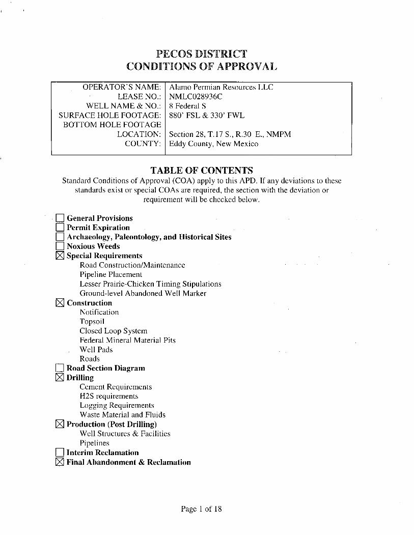
PECOS DISTRICT CONDITIONS OF APPROVAL
OPERATOR'S NAME: Alamo Permian Resources LLC LEASE NO.: NMLC028936C
WELL NAME & NO.: 8 Federal S SURFACE HOLE FOOTAGE: 880' FSL & 330' FWL
BOTTOM HOLE FOOTAGE LOCATION: Section 28, T. 17 S., R.30 E., NMPM
COUNTY: Eddy County, New Mexico
TABLE OF CONTENTS Standard Conditions of Approval (COA) apply to this APD. If any deviations to these
standards exist or special COAs are required, the section with the deviation or requirement will be checked below.
I I General Provisions I I Permit Expiration I I Archaeology, Paleontology, and Historical Sites I I Noxious Weeds IXl Special Requirements
Road Construction/Maintenance Pipeline Placement Lesser Prairie-Chicken Timing Stipulations Ground-level Abandoned Well Marker
^ Construction Notification Topsoil Closed Loop System Federal Mineral Material Pits Well Pads Roads
I I Road Section Diagram M Drilling
Cement Requirements H2S requirements Logging Requirements Waste Material and Fluids
^ Production (Post Drilling) Well Structures & Facilities Pipelines
I I Interim Reclamation [X] Final Abandonment & Reclamation
Page 1 of 18
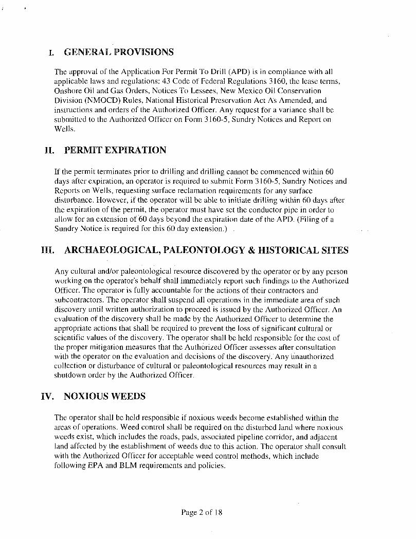
I. GENERAL PROVISIONS
The approval of the Application For Permit To Drill (APD) is in compliance with all applicable laws and regulations: 43 Code of Federal Regulations 3160, the lease terms, Onshore Oil and Gas Orders, Notices To Lessees, New Mexico Oil Conservation Division (NMOCD) Rules, National Historical Preservation Act As Amended, and instructions and orders of the Authorized Officer. Any request for a variance shall be submitted to the Authorized Officer on Form 3160-5, Sundry Notices and Report on Wells.
II. PERMIT EXPIRATION
If the permit terminates prior to drilling and drilling cannot be commenced within 60 days after expiration, an operator is required to submit Form 3160-5, Sundry Notices and Reports on Wells, requesting surface reclamation requirements for any surface disturbance. However, if the operator will be able to initiate drilling within 60 days after the expiration of the permit, the operator must have set the conductor pipe in order to allow for an extension of 60 days beyond the expiration date of the APD. (Filing of a Sundry Notice is required for this 60 day extension.) .
III. ARCHAEOLOGICAL, PALEONTOLOGY & HISTORICAL SITES
Any cultural and/or paleontological resource discovered by the operator or by any person working on the operator's behalf shall immediately report such findings to the Authorized Officer. The operator is fully accountable for the actions of their contractors and subcontractors. The operator shall suspend all operations in the immediate area of such discovery until written authorization to proceed is issued by the Authorized Officer. An evaluation of the discovery shall be made by the Authorized Officer to determine the appropriate actions that shall be required to prevent the loss of significant cultural or scientific values of the discovery. The operator shall be held responsible for the cost of the proper mitigation measures that the Authorized Officer assesses after consultation with the operator on the evaluation and decisions of the discovery. Any unauthorized collection or disturbance of cultural or paleontological resources may result in a shutdown order by the Authorized Officer.
IV. NOXIOUS WEEDS
The operator shall be held responsible if noxious weeds become established within the areas of operations. Weed control shall be required on the disturbed land where noxious weeds exist, which includes the roads, pads, associated pipeline corridor, and adjacent land affected by the establishment of weeds due to this action. The operator shall consult with the Authorized Officer for acceptable weed control methods, which include following EPA and BLM requirements and policies.
Page 2 of 18

V. SPECIAL REQUIREMENT(S)
Road Construction/Maintenance: As stated in Exhibit B-5 of the APD, the existing road from the Federal S #6 well pad to the start of the Federal S #9's new access road cannot be widened more than its current width. This road's current width is 12 feet.
Pipeline Placement: The pipeline must be installed on the north and east side of the road when it travels near the Maddren E #2 well pad as depicted on Exhibit 1-4 of the APD.
Timing Limitation Stipulation / Condition of Approval for lesser prairie-chicken: Oil and gas activities including 3-D geophysical exploration, and drilling will not be allowed in lesser prairie-chicken habitat during the period from March 1st through June 15th annually. During that period, other activities that produce noise or involve human activity, such as the maintenance of oil and gas facilities, pipeline, road, and well pad construction, will be allowed except between 3:00 am and 9:00 am. The 3:00 am to 9:00 am restriction will not apply to normal, around-the-clock operations, such as venting, flaring, or pumping, which do not require a human presence during this period. Additionally, no new drilling will be allowed within up to 200 meters of leks known at the time of permitting. Normal vehicle use on existing roads will not be restricted. Exhaust noise from pump jack engines must be muffled or otherwise controlled so as not to exceed 75 db measured at 30 feet from the source of the noise.
Ground-level Abandoned Well Marker to avoid raptor perching: Upon the plugging and subsequent abandonment of the well, the well marker will be installed at ground level on a plate containing the pertinent information for the plugged well. For more installation details, contact the Carlsbad Field Office at 575-234-5972.
Page 3 of 18

VI. CONSTRUCTION
A. NOTIFICATION
The BLM shall administer compliance and monitor construction of the access road and well pad. Notify the Carlsbad Field Office at (575) 234-5909 at least 3 working days prior to commencing construction of the access road and/or well pad.
When construction operations are being conducted on this well, the operator shall have the approved APD and Conditions of Approval (COA) on the well site and they shall be made available upon request by the Authorized Officer.
B. TOPSOIL
The operator shall stockpile the topsoil in a low profile manner in order to prevent wind/water erosion of the topsoil. The topsoil to be stripped is approximately 6 inches in depth. The topsoil will be used for interim and final reclamation.
C. CLOSED LOOP SYSTEM
Tanks are required for drilling operations: No Pits.
The operator shall properly dispose of drilling contents at an authorized disposal site.
D. FEDERAL MINERAL MATERIALS PIT
Payment shall be made to the BLM prior to removal of any federal mineral materials. Call the Carlsbad Field Office at (575) 234-5972.
E. WELL PAD SURFACING
Surfacing of the well pad is not required.
If the operator elects to surface the well pad, the surfacing material may be required to be removed at the time of reclamation.
The well pad shall be constructed in a manner which creates the smallest possible surface disturbance, consistent with safety and operational needs.
F. EXCLOSURE FENCING (CELLARS & PITS)
Exclosure Fencing The operator will install and maintain exclosure fencing for all open well cellars to prevent access to public, livestock, and large forms of wildlife before and after drilling operations until the pit is free of fluids and the operator initiates backfilling. (For
Page 4 of 18

examples of exclosure fencing design, refer to BLM's Oil and Gas Gold Book, Exclosure Fence Illustrations, Figure 1, Page 18.)
G. ON LEASE ACCESS ROADS
Road Width The access road shall have a driving surface that creates the smallest possible surface disturbance and does not exceed fourteen (14) feet in width. The maximum width of surface disturbance, when constructing the access road, shall not exceed twenty-five (25) feet.
Surfacing Surfacing material is not required on the new access road driving surface. If the operator elects to surface the new access road or pad, the surfacing material may be required to be removed at the time of reclamation.
Where possible, no improvements should be made on the unsurfaced access road other than to remove vegetation as necessary, road irregularities, safety issues, or to fi l l low areas that may sustain standing water.
The Authorized Officer reserves the right to require surfacing of any portion of the access road at any time deemed necessary. Surfacing may be required in the event the road deteriorates, erodes, road traffic increases, or it is determined to be beneficial for future field development. The surfacing depth and type of material will be determined at the time of notification.
Crowning Crowning shall be done on the access road driving surface. The road crown shall have a grade of approximately 2% (i.e., a 1" crown on a 14' wide road). The road shall conform to Figure 1; cross section and plans for typical road construction.
Ditching
Ditching shall be required on both sides of the road.
Turnouts Vehicle turnouts shall be constructed on the road. Turnouts shall be intervisible with interval spacing distance less than 1000 feet. Turnouts shall be constructed on all blind curves. Turnouts shall conform to the following diagram:
Sta nda rd T u rri o ut -P la n Vi ew
, ; ! C e r i t ^
- 4'. . . • v .
" "*<s —— 50'
Page 5 of 18

Drainage Drainage control systems shall be constructed on the entire length of road (e.g. ditches, sidehill outsloping and insloping, lead-off ditches, culvert installation, and low water crossings).
A typical lead-off ditch has a minimum depth of 1 foot below and a berm of 6 inches above natural ground level. The berm shall be on the down-slope side of the lead-off ditch.
Cross Section of a Typical Lead-off Ditch
i<M''rvi feniifn a m?fe e pjW
All lead-off ditches shall be graded to drain water with a 1 percent minimum to 3 percent maximum ditch slope. The spacing interval are variable for lead-off ditches and shall be determined according to the formula for spacing intervals of lead-off ditches, but may be amended depending upon existing soil types and centerline road slope (in % ) ;
Formula for Spacing Interval of Lead-off Ditches
Example - On a 4% road slope that is 400 feet long, the water flow shall drain water into a lead-off ditch. Spacing interval shall be determined by the following formula:
400 foot road with 4% road slope: 400' + 100' = 200' lead-off ditch interval 4%
Cattleguards An appropriately sized cattleguard(s) sufficient to carry out the project shall be installed and maintained at fence crossing(s).
Any existing cattleguard(s) on the access road shall be repaired or replaced if they are damaged or have deteriorated beyond practical use. The operator shall be responsible for the condition of the existing cattleguard(s) that are in place and are utilized during lease operations.
Public Access Public access on this road shall not be restricted by the operator without specific written approval granted by the Authorized Officer.
Page 6 of 18
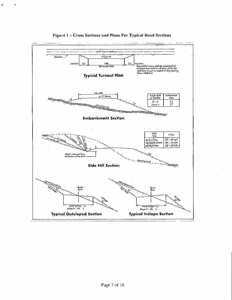
Figure 1 - Cross Sections and Plans Eor Typical Road Sections
- center li-e oT roadway.—^—
rtmiositlO'
'transition 25' 100" 2s:. traniitidn
Ty p ica I Tu r n o u t P lan
,a1[singla'lone iccds cn ell blind curves*wilH • adcJitiono! [iiinmt s as needed to Veep' spacing Be'.owlOOO^eei.' "
fopwidths
E m b a n k m e n t Sect ion
Hsighl of f>0 ^ot ihotilrfer slope.
.above'd'' 3:1
. 2:1
Depth mccsurea from. .Ae'tiottam'of'me dilcK-
ecffh'iu.*tcce
-02 :,:--.04 ft/ft
. 0 2 - . O J f t / f t .
Side Hi l l Sect ion
Page 7 of 18
VII. DRILLING
A. DRILLING OPERATIONS REQUIREMENTS
The BLM is to be notified in advance for a representative to witness:
a. Spudding well (minimum of 24 hours) b. Setting and/or Cementing of all casing strings (minimum of 4 hours) c. BOPE tests (minimum of 4 hours)
£3 Eddy County Call the Carlsbad Field Office, 620 East Greene St., Carlsbad, NM 88220, (575)361-2822
1. A Hydrogen Sulfide (H2S) Drilling Plan shall be activated 500 feet prior to drilling into the Grayburg formation. As a result, the Hydrogen Sulfide area must meet Onshore Order 6 requirements, which includes equipment and personnel/public protection items. If Hydrogen Sulfide is encountered, please provide measured values and formations to the BLM.
2. Unless the production casing has been run and cemented or the well has been properly plugged, the drilling rig shall not be removed from over the hole without prior approval. If the drilling rig is removed without approval - an Incident of Non-Compliance will be written and will be a "Major" violation.
3. Floor controls are required for 3M or Greater systems. These controls will be on the rig floor, unobstructed, readily accessible to the driller and will be operational at all times during drilling and/or completion activities. Rig floor is defined as the area immediately around the rotary table; the area immediately above the substructure on which the draw works is located, this does not include the dog house or stairway area.
4. The record of the drilling rate along with the GR/N well log run from TD to surface shall be submitted to the BLM office as well as all other logs run on the borehole 30 days from completion. If available, a digital copy of the logs is to be submitted in addition to the paper copies. The Rustler top and top and bottom of Salt are to be recorded on the Completion Report.
B. CASING
Changes to the approved APD casing program need prior approval if the items substituted are of lesser grade or different casing size. The Operator can exchange the components of the proposal with that of superior strength (i.e. changing from J-55 to N-80, or from 36# to 40#). Changes to the approved cement program need prior approval if the altered cement plan has less volume or strength or if the changes are substantial (i.e. Multistage tool, ECP, etc.).
Page 8 of 18

Centralizers required on surface casing per Onshore Order 2JII.B.l.f.
Wait on cement (WOC) time prior to drilling out for a primary cement job will be a minimum 18 hours for a water basin, 24 hours in the potash area, or 500 pounds compressive strength, whichever is greater for all casing strings. DURING THIS WOC TIME, NO DRILL PIPE, ETC. SHALL BE RUN IN THE HOLE. Provide compressive strengths including hours to reach required 500 pounds compressive strength prior to cementing each casing string. IF OPERATOR DOES NOT HAVE THE WELL SPECIFIC CEMENT DETAILS ONSITE PRIOR TO PUMPING THE CEMENT FOR EACH CASING STRING, THE WOC WILL BE 30 HOURS. See individual casing strings for details regarding lead cement slurry requirements.
No pea gravel permitted for remedial or fall back remedial without prior authorization from the BLM engineer.
Possibility of water and brine flows in the Salado and Artesia Groups. Possibility of lost circulation in the Grayburg and San Andres formations.
1. The 8-5/8 inch surface casing shall be set at approximately 250 feet (a minimum of 25 feet into the Rustler Anhydrite and above the salt) and cemented to the surface:
a. If cement does not circulate to the surface, the appropriate BLM office shall be notified and a temperature survey utilizing an electronic type temperature survey with surface log readout will be used or a cement bond log shall be run to verify the top of the cement. Temperature survey will be run a minimum of six hours after pumping cement and ideally between 8-10 hours after completing the cement job.
b. Wait on cement (WOC) time for a primary cement job is to include the lead cement slurry.
c. Wait on cement (WOC) time for a remedial job will be a minimum of 4 hours after bringing cement to surface or 500 pounds compressive strength, whichever is greater.
d. If cement falls back, remedial cementing will be done prior to drilling out that string.
2. The minimum required fi l l of cement behind the 5-1/2 inch production casing is:
^ Cement to surface. If cement does not circulate, contact the appropriate BLM office.
Page 9 of 18

3. If hardband drill pipe is rotated inside casing, returns will be monitored for metal. If metal is found in samples, drill pipe will be pulled and rubber protectors which have a larger diameter than the tool joints of the drill pipe will be installed prior to continuing drilling operations.
C. PRESSURE CONTROL
1. All blowout preventer (BOP) and related equipment (BOPE) shall comply with well control requirements as described in Onshore Oil and Gas Order No. 2 and API RP 53 Sec. 17.
2. Minimum working pressure of the blowout preventer (BOP) and related equipment (BOPE) required for drilling below the surface casing shoe shall be 3000 (3M) psi.
3. The appropriate BLM office shall be notified a minimum of 4 hours in advance for a representative to witness the tests.
a. In a water basin, for all casing strings utilizing slips, these are to be set as soon as the crew and rig are ready and any fallback cement remediation has been done. The casing cut-off and BOP installation can be initiated four hours after installing the slips, which will be approximately six hours after bumping the plug. For those casing strings not using slips, the minimum wait time before cut-off is eight hours after bumping the plug. BOP/BOPE testing can begin after cut-off or once cement reaches 500 psi compressive strength (including lead when specified), whichever is greater. However, if the float does not hold, cut-off cannot be initiated until cement reaches 500 psi compressive strength (including lead when specified).
b. The tests shall be done by an independent service company utilizing a test plug not a cup or J-packer.
c. The test shall be run on a 5000 psi chart for a 2-3M BOP/BOP, on a 10000 psi chart for a 5M BOP/BOPE and on a 15000 psi chart for a 10M BOP/BOPE. If a linear chart is used, it shall be a one hour chart. A circular chart shall have a maximum 2 hour clock.
d. The results of the test shall be reported to the appropriate BLM office.
e. All tests are required to be recorded on a calibrated test chart. A copy of the BOP/BOPE test chart and a copy of independent service company test will be submitted to the appropriate BLM office.
Page 10 of 18

f. The BOP/BOPE test shall include a low pressure test from 250 to 300 psi. The test will be held for a minimum of 10 minutes if test is done with a test plug and 30 minutes without a test plug. This test shall be performed prior to the test at full stack pressure.
D. DRILL STEM TEST
If drill stem tests are performed, Onshore Order 2.III.D shall be followed.
E. WASTE MATERIAL AND FLUIDS
All waste (i.e. drilling fluids, trash, salts, chemicals, sewage, gray water, etc.) created as a result of drilling operations and completion operations shall be safely contained and disposed of properly at a waste disposal facility. No waste material or fluid shall be disposed of on the well location or surrounding area.
Porto-johns and trash containers will be on-location during fracturing operations or any other crew-intensive operations.
CRW 071613
Page 11 of 18

VIII. PRODUCTION (POST DRILLING)
A. WELL STRUCTURES & FACILITIES
Placement of Production Facilities Production facilities should be placed on the well pad to allow for maximum interim recontouring and revegetation of the well location.
Exclosure Netting (Open-top Tanks) Immediately following active drilling or completion operations, the operator will take actions necessary to prevent wildlife and livestock access, including avian wildlife, to all open-topped tanks that contain or have the potential to contain salinity sufficient to cause harm to wildlife or livestock, hydrocarbons, or Resource Conservation and Recovery Act of 1976-exempt hazardous substances. At a minimum, the operator will net, screen, or cover open-topped tanks to exclude wildlife and livestock and prevent mortality. If the operator uses netting, the operator will cover and secure the open portion of the tank to prevent wildlife entry. The operator will net, screen, or cover the tanks until the operator removes the tanks from the location or the tanks no longer contain substances that could be harmful to wildlife or livestock. Use a maximum netting mesh size of 1 Vi inches. The netting must not be in contact with fluids and must not have holes or gaps.
Chemical and Fuel Secondary Containment and Exclosure Screening The operator will prevent all hazardous, poisonous, flammable, and toxic substances from coming into contact with soil and water. At a minimum, the operator will install and maintain an impervious secondary containment system for any tank or barrel containing hazardous, poisonous, flammable, or toxic substances sufficient to contain the contents of the tank or barrel and any drips, leaks, and anticipated precipitation. The operator will dispose of fluids within the containment system that do not meet applicable state or U. S. Environmental Protection Agency livestock water standards in accordance with state law; the operator must not drain the fluids to the soil or ground. The operator will design, construct, and maintain all secondary containment systems to prevent wildlife and livestock exposure to harmful substances. At a minimum, the operator will install effective wildlife and livestock exclosure systems such as fencing, netting, expanded metal mesh, lids, and grate covers. Use a maximum netting mesh size of 1 Vi inches.
Open-Vent Exhaust Stack Exclosures The operator will construct, modify, equip, and maintain all open-vent exhaust stacks on production equipment to prevent birds and bats from entering, and to discourage perching, roosting, and nesting. {Recommended exclosure structures on open-vent exhaust stacks are in the shape ofa cone.) Production equipment includes, but may not be limited to, tanks, heater-treaters, separators, dehydrators, flare stacks, in-line units, and compressor mufflers.
Containment Structures Proposed production facilities such as storage tanks and other vessels will have a secondary containment structure that is constructed to hold the capacity of 1.5 times the
Page 12 of 18

largest tank, plus freeboard to account for precipitation, unless more stringent protective requirements are deemed necessary.
Painting Requirement All above-ground structures including meter housing that are not subject to safety requirements shall be painted a flat non-reflective paint color, Shale Green from the BLM Standard Environmental Color Chart (CC-001: June 2008).
B. PIPELINES
STANDARD STIPULATIONS FOR SURFACE INSTALLED PIPELINES
A copy of the application (Grant, Sundry Notice, APD) and attachments, including stipulations, survey plat and/or map, will be on location during construction. BLM personnel may request to you a copy of your permit during construction to ensure compliance with all stipulations.
Holder agrees to comply with the following stipulations to the satisfaction of the Authorized Officer:
1. The holder shall indemnify the United States against any liability for damage to life or property arising from the occupancy or use of public lands under this grant.
2. The holder shall comply with all applicable Federal laws and regulations existing or hereafter enacted or promulgated. In any event, the holder shall comply with the Toxic Substances Control Act of 1976 as amended, 15 USC 2601 et seq.. (1982) with regards to any toxic substances that are used, generated by or stored on the right-of-way or on facilities authorized under this right-of-way grant. (See 40 CFR, Part 702-799 and especially, provisions on polychlorinated biphenyls, 40 CFR 761.1-761.193.) Additionally, any release of toxic substances (leaks, spills, etc.) in excess of the reportable quantity established by 40 CFR, Part 117 shall be reported as required by the Comprehensive Environmental Response, Compensation, and Liability Act, section 102b. A copy of any report required or requested by any Federal agency or State government as a result of a reportable release or spill of any toxic substances shall be furnished to the authorized officer concurrent with the filing of the reports to the involved Federal agency or State government.
3. The holder agrees to indemnify the United States against any liability arising from the release of any hazardous substance or hazardous waste (as these terms are defined in the Comprehensive Environmental Response, Compensation and Liability Act of 1980, 42 U.S.C. 9601, et seg. or the Resource Conservation and Recovery Act, 42 U.S.C. 6901, et seq.) on the Right-of-Way (unless the release or threatened release is wholly unrelated to activity of the Right-of-Way holder's activity on the Right-of-Way), or resulting from the activity of the Right-of-Way holder on the Right-of-Way. This agreement applies without regard to whether a release is caused by the holder, its agent, or unrelated third parties.
Page 13 of 18

4. The holder shall be liable for damage or injury to the United States to the extent provided by 43 CFR Sec. 2883.1-4. The holder shall be held to a standard of strict liability for damage or injury to the United States resulting from pipe rupture, fire, or spills caused or substantially aggravated by any of the following within the right-of-way or permit area:
a. Activities of the holder including, but not limited to construction, operation, maintenance, and termination of the facility.
b. Activities of other parties including, but not limited to: (1) Land clearing. (2) Earth-disturbing and earth-moving work. (3) Blasting. (4) Vandalism and sabotage.
c. Acts of God.
The maximum limitation for such strict liability damages shall not exceed one million dollars ($1,000,000) for any one event, and any liability in excess of such amount shall be determined by the ordinary rules of negligence of the jurisdiction in which the damage or injury occurred.
This section shall not impose strict liability for damage or injury resulting primarily from an act of war or from the negligent acts or omissions of the United States.
5. If, during any phase of the construction, operation, maintenance, or termination of the pipeline, any oil, salt water, or other pollutant should be discharged from the pipeline system, impacting Federal lands, the control and total removal, disposal, and cleaning up of such oil, salt water, or other pollutant, wherever found, shall be the responsibility of the holder, regardless of fault. Upon failure of the holder to control, dispose of, or clean up such discharge on or affecting Federal lands, or to repair all damages resulting therefrom, on the Federal lands, the Authorized Officer may take such measures as he deems necessary to control and clean up the discharge and restore the area, including, where appropriate, the aquatic environment and fish and wildlife habitats, at the full expense of the holder. Such action by the Authorized Officer shall not relieve the holder of any responsibility as provided herein.
6. All construction and maintenance activity will be confined to the authorized right-of-way width of 20 feet. If the pipeline route follows an existing road or buried pipeline right-of-way, the surface pipeline must be installed no farther than 10 feet from the edge of the road or buried pipeline right-of-way. If existing surface pipelines prevent this distance, the proposed surface pipeline must be installed immediately adjacent to the outer surface pipeline. All construction and maintenance activity will be confined to existing roads or right-of-ways.
7. No blading or clearing of any vegetation will be allowed unless approved in writing by the Authorized Officer.
Page 14 of 18

8. The holder shall install the pipeline on the surface in such a manner that will minimize suspension of the pipeline across low areas in the terrain. In hummocky of duney areas, the pipeline will be "snaked" around hummocks and dunes rather then suspended across these features.
9. The pipeline shall be buried with a minimum of 24 inches under all roads, "two-tracks," and trails. Burial of the pipe will continue for 20 feet on each side of each crossing. The condition of the road, upon completion of construction, shall be returned to at least its former state with no bumps or dips remaining in the road surface.
10. The holder shall minimize disturbance to existing fences and other improvements on public lands. The holder is required to promptly repair improvements to at least their former state. Functional use of these improvements will be maintained at all times. The holder will contact the owner of any improvements prior to disturbing them. When necessary to pass through a fence line, the fence shall be braced on both sides of the passageway prior to cutting of the fence. No permanent gates will be allowed unless approved by the Authorized Officer.
11. In those areas where erosion control structures are required to stabilize soil conditions, the holder will install such structures as are suitable for the specific soil conditions being encountered and which are in accordance with sound resource management practices.
12. Excluding the pipe, all above-ground structures not subject to safety requirement shall be painted by the holder to blend with the natural color of the landscape. The paint used shall be a color which simulates "Standard Environmental Colors" - Shale Green, Murisell Soil Color No. 5Y 4/2; designated by the Rocky Mountain Five State Interagency Committee.
13. The pipeline will be identified by signs at the point of origin and completion of the right-of-way and at all road crossings. At a minimum, signs will state the holder's name, BLM serial number, and the product being transported. Signs will be maintained in a legible condition for the life of the pipeline.
14. The holder shall not use the pipeline route as a road for purposes other than routine maintenance as determined necessary by the Authorized Officer in consultation with the holder. The holder will take whatever steps are necessary to ensure that the pipeline route is not used as a roadway.
15. Any cultural and/or paleontological resource (historic or prehistoric site or object) discovered by the holder, or any person working on his behalf, on public or Federal land shall be immediately reported to the authorized officer. Holder shall suspend all operations in the immediate area of such discovery until written authorization to proceed is issued by the authorized officer. An evaluation of the discovery will be made by the authorized officer to determine appropriate cultural or scientific values. The holder will
Page 15 of 18

be responsible for the cost of evaluation and any decision as to proper mitigation measures will be made by the authorized officer after consulting with the holder.
16. The operator shall be held responsible if noxious weeds become established within the areas of operations. Weed control shall be required on the disturbed land where noxious weeds exist, which includes the roads, powerline corridor, and adjacent land affected by the establishment of weeds due to this action. The operator shall consult with the Authorized Officer for acceptable weed control methods, which include following EPA and BLM requirements and policies.
17. Surface pipelines must be less than or equal to 4 inches and a working pressure below 125 psi.
IX. INTERIM RECLAMATION
During the life of the development, all disturbed areas not needed for active support of production operations should undergo interim reclamation in order to minimize the environmental impacts of development on other resources and uses.
Within six (6) months of well completion, operators should work with BLM surface management specialists (Jim Amos: 575-234-5909) to devise the best strategies to reduce the size of the location. Interim reclamation should allow for remedial well operations, as well as safe and efficient removal of oil and gas.
During reclamation, the removal of caliche is important to increasing the success of revegetating the site. Removed caliche that is free of contaminants may be used for road repairs, fire walls or for building other roads and locations. In order to operate the well or complete workover operations, it may be necessary to drive, park and operate on restored interim vegetation within the previously disturbed area. Disturbing revegetated areas for production or workover operations will be allowed. If there is significant disturbance and loss of vegetation, the area will need to be revegetated. Communicate with the appropriate BLM office for any exceptions/exemptions if needed.
All disturbed areas after they have been satisfactorily prepared need to be reseeded with the seed mixture provided below.
Upon completion of interim reclamation, the operator shall submit a Sundry Notices and Reports on Wells, Subsequent Report of Reclamation (Form 3160-5).
X. FINAL ABANDONMENT & RECLAMATION
At final abandonment, well locations, production facilities, and access roads must undergo "final" reclamation so that the character and productivity of the land are restored.
Page 16 of 18

Earthwork for final reclamation must be completed within six (6) months of well plugging. All pads, pits, facility locations and roads must be reclaimed to a satisfactory revegetated, safe, and stable condition, unless an agreement is made with the landowner or BLM to keep the road and/or pad intact.
After all disturbed areas have been satisfactorily prepared, these areas need to be revegetated with the seed mixture provided below. Seeding should be accomplished by drilling on the contour whenever practical or by other approved methods. Seeding may need to be repeated until revegetation is successful, as determined by the BLM.
Operators shall contact a BLM surface protection specialist prior to surface abandonment operations for site specific objectives (Jim Amos: 575-234-5909).
Ground-level Abandoned Well Marker to avoid raptor perching: Upon the plugging and subsequent abandonment of the well, the well marker will be installed at ground level on a plate containing the pertinent information for the plugged well.
Page 17 of 18

Seed Mixture 2, for Sandy Sites
The holder shall seed all disturbed areas with the seed mixture listed below. The seed mixture shall be planted in the amounts specified in pounds of pure live seed (PLS)* per acre. There shall be no primary or secondary noxious weeds in the seed mixture. Seed will be tested and the viability testing of seed will be done in accordance with State law (s) and within nine (9) months prior to purchase. Commercial seed will be either certified or registered seed. The seed container will be tagged in accordance with State law(s) and available for inspection by the authorized officer.
Seed will be planted using a drill equipped with a depth regulator to ensure proper depth of planting where drilling is possible. The seed mixture will be evenly and uniformly planted over the disturbed area (smaller/heavier seeds have a tendency to drop the bottom of the drill and are planted first). The holder shall take appropriate measures to ensure this does not occur. Where drilling is not possible, seed will be broadcast and the area shall be raked or chained to cover the seed. When broadcasting the seed, the pounds per acre are to be doubled. The seeding will be repeated until a satisfactory stand is established as determined by the authorized officer. Evaluation of growth will not be made before completion of at least one full growing season after seeding.
Species to be planted in pounds of pure live seed* per acre:
Species lb/acre
Sand dropseed (Sporobolus cryptahdrus) 1.0 Sand love grass (Eragrostis trichodes) 1.0 Plains bristlegrass (Setaria macrostachya) 2.0
*Pounds of pure live seed:
Pounds of seed x percent purity x percent germination = pounds pure live seed
Page 18 of 18