Embed Size (px)
Citation preview
Low-energy welding (LEW) isunique in that the process weldswithout distorting the substrate,
nor creating a heat-affected zone(HAZ) or any residual stresses andstrains in the material (Ref. 1). Largelybecause of its incredibly fast coolingrates, in many cases LEW can weld dis-similar materials that other processescannot weld easily or at all (Ref. 2). Itis a quick, micro-arc, pulsed, capacitor
discharge as well as an electronicallycontrolled process that applies meltedmaterial to a nominally conductivesurface (Ref. 3). As the name suggests,little energy is injected into the welds.The machines are portable, easy touse, cost effective in terms of bothcapital and operating costs, and envi-ronmentally friendly. The process useslittle electricity and creates little waste(Ref. 4).
Sources of Growth inLEW
Automation
As you would expect from the char-acteristics, the LEW process is versa-tile. Previously named electric sparkdeposition (ESD) or pulsed electrodedeposition (PED), the term LEW is
WELDING JOURNAL / NOVEMBER 201742
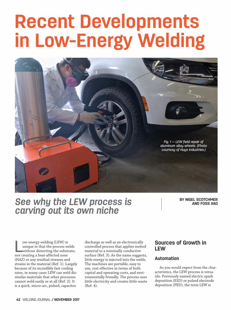
See why the LEW process iscarving out its own niche
BY NIGEL SCOTCHMER AND FOSS JIAO
Recent Developmentsin Low-Energy Welding
Fig. 1 — LEW field repair of aluminum alloy wheels. (Photocourtesy of Huys Industries.)
Scotchmer (Huys) Layout.qxp_Layout 1 10/9/17 8:21 AM Page 42
generally preferred today because itspower supplies have become morepowerful, controllable, and program-mable, and their applicators have be-come broader in the range of their me-chanical functions (variably rotating,vibratory, and both rotational and vi-brational). The automation of theprocess itself has grown with theneeds and capabilities of metal print-ing and additive manufacturing (Ref.5). Its fast cooling rate and low heatinput reduces the potential for diffu-sion, facilitating the use of lower gradematerials treated with LEW to meetthe same performance requirementsof more expensive alloys. The LEW process deposits materialby creating a momentary short circuitbetween a moving electrode made upof the filler or additive material, andthe substrate. Because short circuitingheats only a very small volume of thesubstrate near the produced electric arccombined with the momentary natureof the electric arcing, the overall heatgenerated and transferred to the sub-strate is relatively minimal (Ref. 1).Moreover, the small melted volume re-sulting from such short circuiting canalso be transferred out of the deposi-tion area more quickly via conductionthrough the relatively large substrate.At the same time, the material transfermechanism of the LEW process leadsto a metallurgical bond between thedeposited material and the substrate. Thus the LEW process makes an at-tractive candidate for surface modifi-cation and for the restoration of high-value components (superalloys, hy-brid-manufactured items, injectionmolds, and turbine blades). It providesa fine microstructure, permitting littlediffusion, and reduces intermetallic
compounds that allow for nonequilib-rium metastable phases (Ref. 6). In-conels, cermets, refractory materials,heat-susceptible materials (precipi-tate-hardened elements, low-melting-temperature alloys), and residualstress-susceptible compounds such asthinner walled, lower weight, and pre-cision components will benefit fromthese characteristics. Industries push-ing to develop higher tolerances, com-plex alloy content, and advanced heattreatments, or making new materialssusceptible to heat damage from tradi-tional welding techniques also benefitfrom this process. Combined with itslower capital costs compared to someother advanced welding techniques,LEW’s appeal is clear.
Additive Manufacturing
The rapid growth in additive manu-facturing is another source for thegrowth. Surface defects can be re-moved, and the finish, hardness, cor-rosion resistance, and other character-istics can be improved. The popularityof LEW is increasing due to recent de-velopments in digital and electronicpower control; a wider range of appli-cators; improvements in control mech-anisms such as force and voltage feed-back; and advances in vision software.These developments allow for both awider range of materials and thick-nesses to be welded (for both coatingsand repairs) due to the superior man-agement of the intermittent contactand energy pulses of the process. Nowthe quality of the weldments, the rateof deposition, and the thickness ofdepositions achieved have increasedsignificantly (Ref. 7). In its early years, LEW was primari-
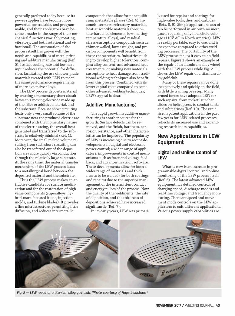
ly used for repairs and coatings forhigh-value tools, dies, and carbides(Refs. 8, 9). Simple applications can of-ten be performed in air, with no inertgases, requiring only household volt-age (110V AC in North America). LEWis readily portable, easy to use, and isinexpensive compared to other weld-ing processes. The portability of theLEW process makes it easy to do fieldrepairs. Figure 1 shows an example ofthe repair of an aluminum alloy wheelwith the LEW process while Fig. 2shows the LEW repair of a titanium al-loy golf club. Many of these repairs can be doneinexpensively and quickly, in the field,with little training or setup. Manyarmed forces have adopted LEW forsuch repairs, from rocket launcherslides on helicopters, to combat tanksand submarines (Ref. 10). The rapidrise in patent applications in the pastfew years for LEW-related processesreflects its increased use and expand-ing research in its capabilities.
New Applications in LEWEquipment
Digital and Online Control ofLEW
What is new is an increase in pro-grammable digital control and onlinemonitoring of the LEW process itself(Ref. 5). The latest advanced LEWequipment has detailed controls ofcharging speed, discharge modes andreal-time voltage, and frequency mon-itoring. There are speed and move-ment mode controls on the LEW ap-plicators to suit different applications.Various power supply capabilities are
NOVEMBER 2017 / WELDING JOURNAL 43
Fig. 2 — LEW repair of a titanium alloy golf club. (Photo courtesy of Huys Industries.)
Scotchmer (Huys) Layout.qxp_Layout 1 10/9/17 8:21 AM Page 43
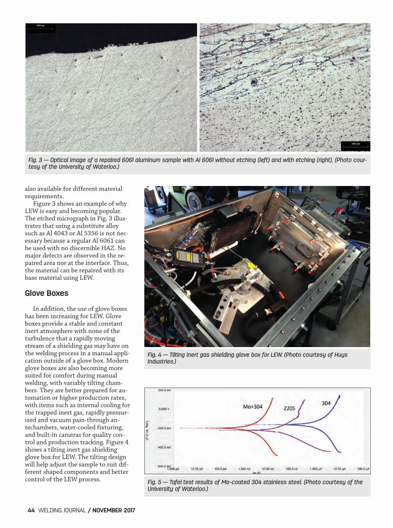
also available for different material requirements. Figure 3 shows an example of whyLEW is easy and becoming popular.The etched micrograph in Fig. 3 illus-trates that using a substitute alloysuch as Al 4043 or Al 5356 is not nec-essary because a regular Al 6061 canbe used with no discernible HAZ. Nomajor defects are observed in the re-paired area nor at the interface. Thus,the material can be repaired with itsbase material using LEW.
Glove Boxes
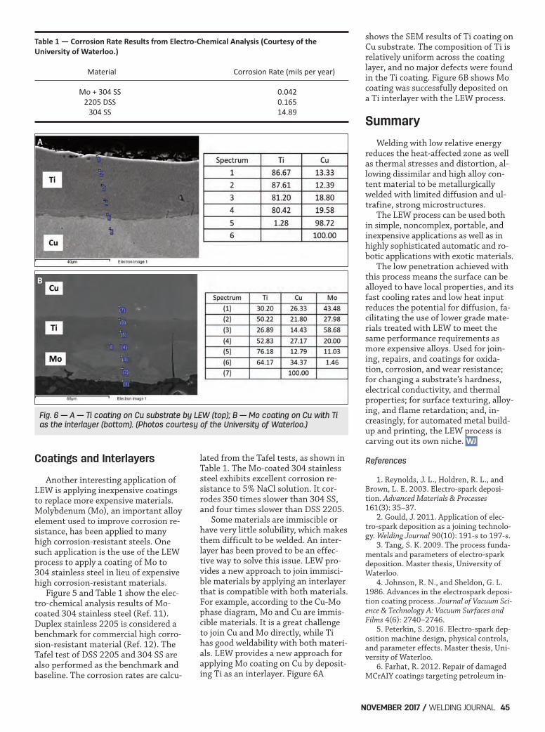
In addition, the use of glove boxeshas been increasing for LEW. Gloveboxes provide a stable and constantinert atmosphere with none of theturbulence that a rapidly movingstream of a shielding gas may have onthe welding process in a manual appli-cation outside of a glove box. Modernglove boxes are also becoming moresuited for comfort during manualwelding, with variably tilting cham-bers. They are better prepared for au-tomation or higher production rates,with items such as internal cooling forthe trapped inert gas, rapidly pressur-ized and vacuum pass-through an-techambers, water-cooled fixturing,and built-in cameras for quality con-trol and production tracking. Figure 4shows a tilting inert gas shieldingglove box for LEW. The tilting designwill help adjust the sample to suit dif-ferent shaped components and bettercontrol of the LEW process.
WELDING JOURNAL / NOVEMBER 201744
Fig. 3 — Optical image of a repaired 6061 aluminum sample with Al 6061 without etching (left) and with etching (right). (Photo cour-tesy of the University of Waterloo.)
Fig. 4 — Tilting inert gas shielding glove box for LEW. (Photo courtesy of Huys Industries.)
Fig. 5 — Tafel test results of Mo-coated 304 stainless steel. (Photo courtesy of theUniversity of Waterloo.)
Scotchmer (Huys) Layout.qxp_Layout 1 10/9/17 8:22 AM Page 44
Coatings and Interlayers
Another interesting application ofLEW is applying inexpensive coatingsto replace more expensive materials.Molybdenum (Mo), an important alloyelement used to improve corrosion re-sistance, has been applied to manyhigh corrosion-resistant steels. Onesuch application is the use of the LEWprocess to apply a coating of Mo to304 stainless steel in lieu of expensivehigh corrosion-resistant materials. Figure 5 and Table 1 show the elec-tro-chemical analysis results of Mo-coated 304 stainless steel (Ref. 11).Duplex stainless 2205 is considered abenchmark for commercial high corro-sion-resistant material (Ref. 12). TheTafel test of DSS 2205 and 304 SS arealso performed as the benchmark andbaseline. The corrosion rates are calcu-
lated from the Tafel tests, as shown inTable 1. The Mo-coated 304 stainlesssteel exhibits excellent corrosion re-sistance to 5% NaCl solution. It cor-rodes 350 times slower than 304 SS,and four times slower than DSS 2205. Some materials are immiscible orhave very little solubility, which makesthem difficult to be welded. An inter-layer has been proved to be an effec-tive way to solve this issue. LEW pro-vides a new approach to join immisci-ble materials by applying an interlayerthat is compatible with both materials.For example, according to the Cu-Mophase diagram, Mo and Cu are immis-cible materials. It is a great challengeto join Cu and Mo directly, while Tihas good weldability with both materi-als. LEW provides a new approach forapplying Mo coating on Cu by deposit-ing Ti as an interlayer. Figure 6A
shows the SEM results of Ti coating onCu substrate. The composition of Ti isrelatively uniform across the coatinglayer, and no major defects were foundin the Ti coating. Figure 6B shows Mocoating was successfully deposited ona Ti interlayer with the LEW process.
Summary
Welding with low relative energyreduces the heat-affected zone as wellas thermal stresses and distortion, al-lowing dissimilar and high alloy con-tent material to be metallurgicallywelded with limited diffusion and ul-trafine, strong microstructures. The LEW process can be used bothin simple, noncomplex, portable, andinexpensive applications as well as inhighly sophisticated automatic and ro-botic applications with exotic materials. The low penetration achieved withthis process means the surface can bealloyed to have local properties, and itsfast cooling rates and low heat inputreduces the potential for diffusion, fa-cilitating the use of lower grade mate-rials treated with LEW to meet thesame performance requirements asmore expensive alloys. Used for join-ing, repairs, and coatings for oxida-tion, corrosion, and wear resistance;for changing a substrate’s hardness,electrical conductivity, and thermalproperties; for surface texturing, alloy-ing, and flame retardation; and, in-creasingly, for automated metal build-up and printing, the LEW process iscarving out its own niche.
References
1. Reynolds, J. L., Holdren, R. L., andBrown, L. E. 2003. Electro-spark deposi-tion. Advanced Materials & Processes161(3): 35–37. 2. Gould, J. 2011. Application of elec-tro-spark deposition as a joining technolo-gy. Welding Journal 90(10): 191-s to 197-s. 3. Tang, S. K. 2009. The process funda-mentals and parameters of electro-sparkdeposition. Master thesis, University ofWaterloo. 4. Johnson, R. N., and Sheldon, G. L.1986. Advances in the electrospark deposi-tion coating process. Journal of Vacuum Sci-ence & Technology A: Vacuum Surfaces andFilms 4(6): 2740–2746. 5. Peterkin, S. 2016. Electro-spark dep-osition machine design, physical controls,and parameter effects. Master thesis, Uni-versity of Waterloo. 6. Farhat, R. 2012. Repair of damagedMCrAIY coatings targeting petroleum in-
NOVEMBER 2017 / WELDING JOURNAL 45
WJ
Fig. 6 — A — Ti coating on Cu substrate by LEW (top); B — Mo coating on Cu with Tias the interlayer (bottom). (Photos courtesy of the University of Waterloo.)
Table 1 — Corrosion Rate Results from ElectroChemical Analysis (Courtesy of the University of Waterloo.)
Material Corrosion Rate (mils per year)
Mo + 304 SS 0.042 2205 DSS 0.165 304 SS 14.89
A
B
Scotchmer (Huys) Layout.qxp_Layout 1 10/9/17 8:22 AM Page 45


![Welding Mechanics and Fracture Assessment - 大阪大学 · Recent progress in welding mechanics and fracture assessment ... Performance of Welded Joints [6] - Fatigue Design and](https://img.pdfslide.net/doc/110x75/5af290577f8b9a8b4c90580c/welding-mechanics-and-fracture-assessment-progress-in-welding-mechanics.jpg)