Embed Size (px)
Citation preview
13
WarningFORMULA disk brakes are designed solely for use on human powered 2wheel vehicles. Other applications will void the warranty and releases
FORMULA of any responsibility for eventual damages or consequential damages.
RECOMMENDED BRAKE FLUID, GREASE AND ADHESIVES
Hydraulic brake fluidUse only DOT 3, DOT 4 or DOT5 hydraulic brake fluid from sealed containers.Do not leave the container open over a period of time because this product absorbs themoisture in the air, which alters its physical characteristics. FORMULA recommends toreplace the fluid in the system every 2 years.
WarningThe fluid in the brake system, besides possibly damaging the paintjob, isextremely hazardous in case of contact with the eyes or skin. In case of
accidental contact flush abundantly with water. Never mix DOT 5 with DOT 3 or DOT4, this may result in a very aggressive combination that is destructive for rubber seals.FORMULA recommends wearing protective gloves during installation or maintenanceof the hydraulic system.Safe the environment, don’t drain brake fluid !
GreaseUse silicon grease for EPDM seals. FORMULA recommends: UNISILKON TKN 1011 byKLUBER.
Danger!Use of inappropriate type of grease may compromise the integrity of theseals and cause damage to the system which may cause severe accidents.
AdhesivesWhere specified use:– Loctite 222 or similar for light adhesion.– Loctite 242 or similar for medium adhesion.
CleaningTo clean the parts use biodegradable solvents
SPECIFIC TOOLS
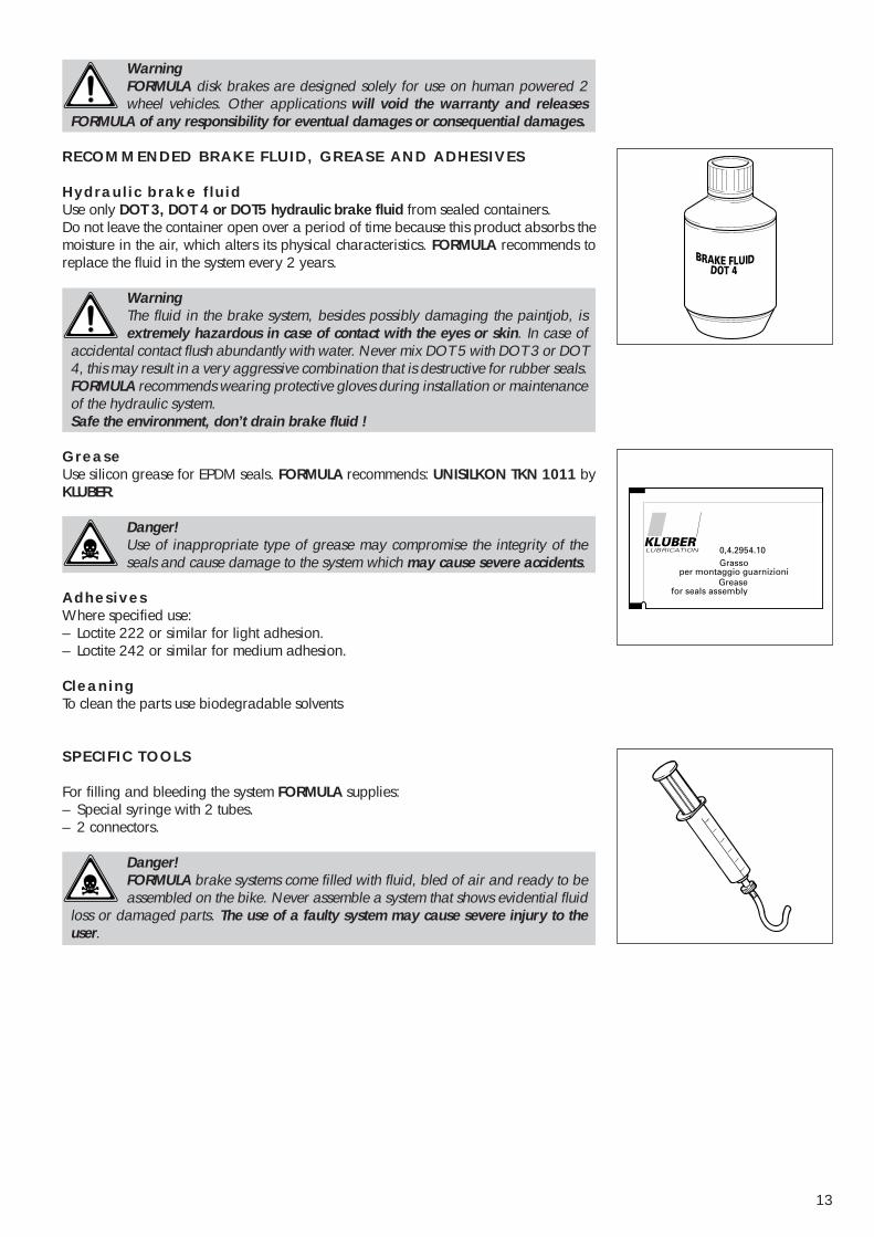
For filling and bleeding the system FORMULA supplies:– Special syringe with 2 tubes.– 2 connectors.
Danger!FORMULA brake systems come filled with fluid, bled of air and ready to beassembled on the bike. Never assemble a system that shows evidential fluid
loss or damaged parts. The use of a faulty system may cause severe injury to theuser.
14
3
4
5
1
2
51
7
48.55
6
1 - INTRODUCTION TO THE VARIOUS FORMULA DISK BRAKES
With the objective to improve the function of the brakes and adapt them to the differentmarket requirements, FORMULA continues to develop new products. This has increasedthe number of products FORMULA now offers.To help people working with FORMULA brakes get a better understanding we haveoutlined the different FORMULA products and their functions.
FORMULA produces:Pumplevers: with and without compensation chamberFluid tubes: with fixed or reattacheable fittingsCalipers: FORMULA standard or international standardConnectors: with eyelet for 90 degree tubefixationDisks: fixed or repairable
These are the differences:
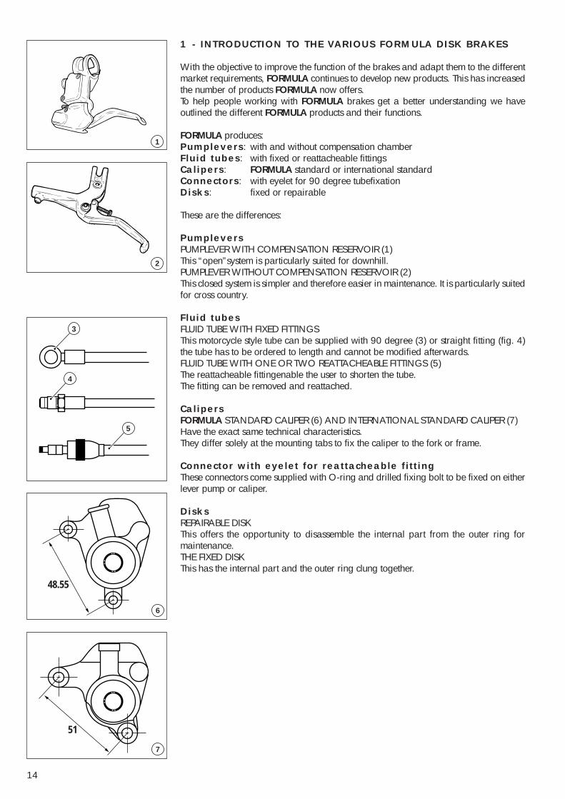
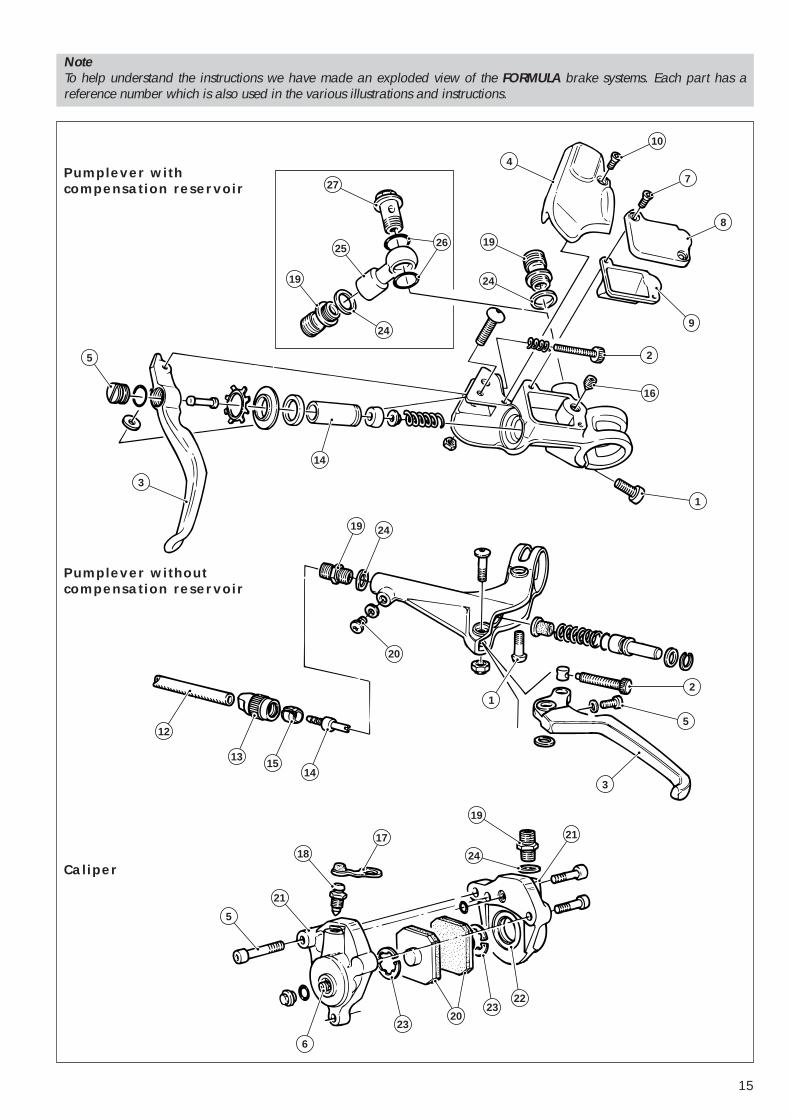
PumpleversPUMPLEVER WITH COMPENSATION RESERVOIR (1)This “open”system is particularly suited for downhill.PUMPLEVER WITHOUT COMPENSATION RESERVOIR (2)This closed system is simpler and therefore easier in maintenance. It is particularly suitedfor cross country.
Fluid tubesFLUID TUBE WITH FIXED FITTINGSThis motorcycle style tube can be supplied with 90 degree (3) or straight fitting (fig. 4)the tube has to be ordered to length and cannot be modified afterwards.FLUID TUBE WITH ONE OR TWO REATTACHEABLE FITTINGS (5)The reattacheable fittingenable the user to shorten the tube.The fitting can be removed and reattached.
CalipersFORMULA STANDARD CALIPER (6) AND INTERNATIONAL STANDARD CALIPER (7)Have the exact same technical characteristics.They differ solely at the mounting tabs to fix the caliper to the fork or frame.
Connector with eyelet for reattacheable fittingThese connectors come supplied with O-ring and drilled fixing bolt to be fixed on eitherlever pump or caliper.
DisksREPAIRABLE DISKThis offers the opportunity to disassemble the internal part from the outer ring formaintenance.THE FIXED DISKThis has the internal part and the outer ring clung together.
15
Pumplever withcompensation reservoir
Pumplever withoutcompensation reservoir
19 24
20
2
5
3
1
12
1315
14
21
19
24
17
18
21
6
23
2322
20
5
27
4
10
7
8
9
2
16
1
14
3
5
19
24
25
24
19
26
Caliper
NoteTo help understand the instructions we have made an exploded view of the FORMULA brake systems. Each part has areference number which is also used in the various illustrations and instructions.
16
3
2
1 mm
4
A
B
Fig. 3
Fig. 2
1
Fig. 1
2 - MOUNTING OF THE BRAKE SYSTEM ON THE BICYCLE
PremiseThe FORMULA brake systems are supplied ready for use. Avoid tampering with thesystem before reading the instructions provided in this manual.
Danger!Improper assembly of the wheels or malfunction of the brake system may beextremely hazardous and could cause accidents, even fatal ones.
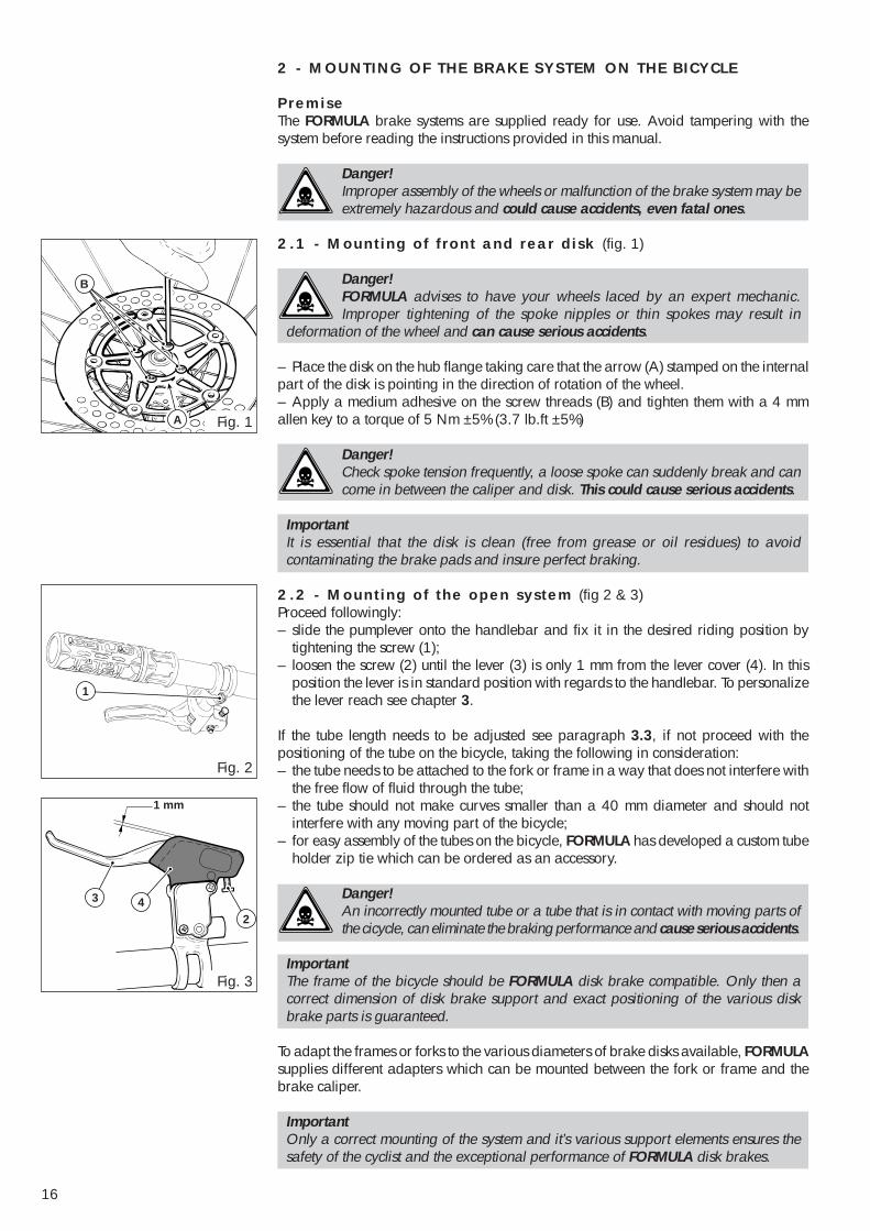
2.1 - Mounting of front and rear disk (fig. 1)
Danger!FORMULA advises to have your wheels laced by an expert mechanic.Improper tightening of the spoke nipples or thin spokes may result in
deformation of the wheel and can cause serious accidents.
– Place the disk on the hub flange taking care that the arrow (A) stamped on the internalpart of the disk is pointing in the direction of rotation of the wheel.– Apply a medium adhesive on the screw threads (B) and tighten them with a 4 mmallen key to a torque of 5 Nm ±5% (3.7 lb.ft ±5%)
Danger!Check spoke tension frequently, a loose spoke can suddenly break and cancome in between the caliper and disk. This could cause serious accidents.
ImportantIt is essential that the disk is clean (free from grease or oil residues) to avoidcontaminating the brake pads and insure perfect braking.
2.2 - Mounting of the open system (fig 2 & 3)Proceed followingly:– slide the pumplever onto the handlebar and fix it in the desired riding position by
tightening the screw (1);– loosen the screw (2) until the lever (3) is only 1 mm from the lever cover (4). In this
position the lever is in standard position with regards to the handlebar. To personalizethe lever reach see chapter 3.
If the tube length needs to be adjusted see paragraph 3.3, if not proceed with thepositioning of the tube on the bicycle, taking the following in consideration:– the tube needs to be attached to the fork or frame in a way that does not interfere with
the free flow of fluid through the tube;– the tube should not make curves smaller than a 40 mm diameter and should not
interfere with any moving part of the bicycle;– for easy assembly of the tubes on the bicycle, FORMULA has developed a custom tube
holder zip tie which can be ordered as an accessory.
Danger!An incorrectly mounted tube or a tube that is in contact with moving parts ofthe cicycle, can eliminate the braking performance and cause serious accidents.
ImportantThe frame of the bicycle should be FORMULA disk brake compatible. Only then acorrect dimension of disk brake support and exact positioning of the various diskbrake parts is guaranteed.
To adapt the frames or forks to the various diameters of brake disks available, FORMULAsupplies different adapters which can be mounted between the fork or frame and thebrake caliper.
ImportantOnly a correct mounting of the system and it’s various support elements ensures thesafety of the cyclist and the exceptional performance of FORMULA disk brakes.
17
==
C 6
5
5
Fig. 5
Fig. 4
Fig. 6
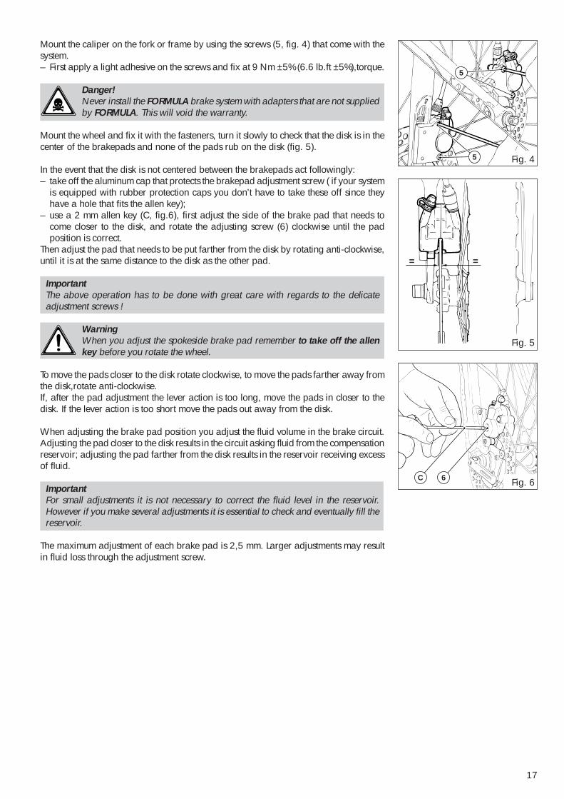
Mount the caliper on the fork or frame by using the screws (5, fig. 4) that come with thesystem.– First apply a light adhesive on the screws and fix at 9 Nm ±5% (6.6 lb.ft ±5%),torque.
Danger!Never install the FORMULA brake system with adapters that are not suppliedby FORMULA. This will void the warranty.
Mount the wheel and fix it with the fasteners, turn it slowly to check that the disk is in thecenter of the brakepads and none of the pads rub on the disk (fig. 5).
In the event that the disk is not centered between the brakepads act followingly:– take off the aluminum cap that protects the brakepad adjustment screw ( if your system
is equipped with rubber protection caps you don’t have to take these off since theyhave a hole that fits the allen key);
– use a 2 mm allen key (C, fig.6), first adjust the side of the brake pad that needs tocome closer to the disk, and rotate the adjusting screw (6) clockwise until the padposition is correct.
Then adjust the pad that needs to be put farther from the disk by rotating anti-clockwise,until it is at the same distance to the disk as the other pad.
ImportantThe above operation has to be done with great care with regards to the delicateadjustment screws !
WarningWhen you adjust the spokeside brake pad remember to take off the allenkey before you rotate the wheel.
To move the pads closer to the disk rotate clockwise, to move the pads farther away fromthe disk,rotate anti-clockwise.If, after the pad adjustment the lever action is too long, move the pads in closer to thedisk. If the lever action is too short move the pads out away from the disk.
When adjusting the brake pad position you adjust the fluid volume in the brake circuit.Adjusting the pad closer to the disk results in the circuit asking fluid from the compensationreservoir; adjusting the pad farther from the disk results in the reservoir receiving excessof fluid.
ImportantFor small adjustments it is not necessary to correct the fluid level in the reservoir.However if you make several adjustments it is essential to check and eventually fill thereservoir.
The maximum adjustment of each brake pad is 2,5 mm. Larger adjustments may resultin fluid loss through the adjustment screw.
18
==
1
7 8
9
2
Fig. 7
Fig. 8
Fig. 9
Fig. 10
2.3 - Correcting the fluid level of the compensation reservoir(fig. 7)After the pad adjusting procedure:– position the pumplever horizontally on the handlebar;– loosen the screws (7) of the reservoir lid (8). Take the lid off;– take out the rubber diaphragm (9);– check the fluid level, it may have dropped when adjusting the pads. If necessary fill the
reservoir to the brim using only DOT 3, 4 or 5 hydraulic brake fluid;
ImportantAny other fluid may cause irreparable damages to the system. Use brake fluid fromsealed containers.
WarningProtect vital parts of the bike from spilling brake fluid by holding a ragaround the reservoir, use protective gloves when working with brake fluid.
– reassemble the diaphragm and the lid to the reservoir, wrap a rag around the pumpleverto avoid spill of excess fluid on the bicycle or floor (the fluid needs to spill over to besure no air is trapped in the reservoir);
– clean the pumplever and rotate the pumplever to the desired riding position and fix it.
ImportantCheck that after the above operation no fluid has dropped on the disk.this is to avoidcontamination of the brake pads and to ensure a perfect brake performance rightfrom the start.
Mounted according to the above instruction the brake system will be free of air andready to roll.
2.4 - Mounting of the closed systemSlide the pumplever on the handlebar in the desired riding position and fix it with screw(1, fig. 8).At this moment the lever is in the standard position. To adjust the lever reach see thechapter 3.If the tube length needs to be adjusted see paragraph 3.3, if not proceed with themounting of the tube on the bicycle as indicated in paragraph 2.2.Mount the caliper on the fork or frame following the instructions in paragraph 2.2, so:– mount the wheel and fix it with the fasteners;– turn it slowly to check that the disk is in the center of the brakepads and none of the
pads rub on the disk (fig. 9);– adjust the desired lever action by turning screw (2, fig. 10) when turning this screw the
brake pads move closer to the disk or farther away from the disk.
19
3
25
2
11
A
10
4
Fig. 11
Fig. 12
Fig. 13
Fig. 14
5
A
Fig. 15
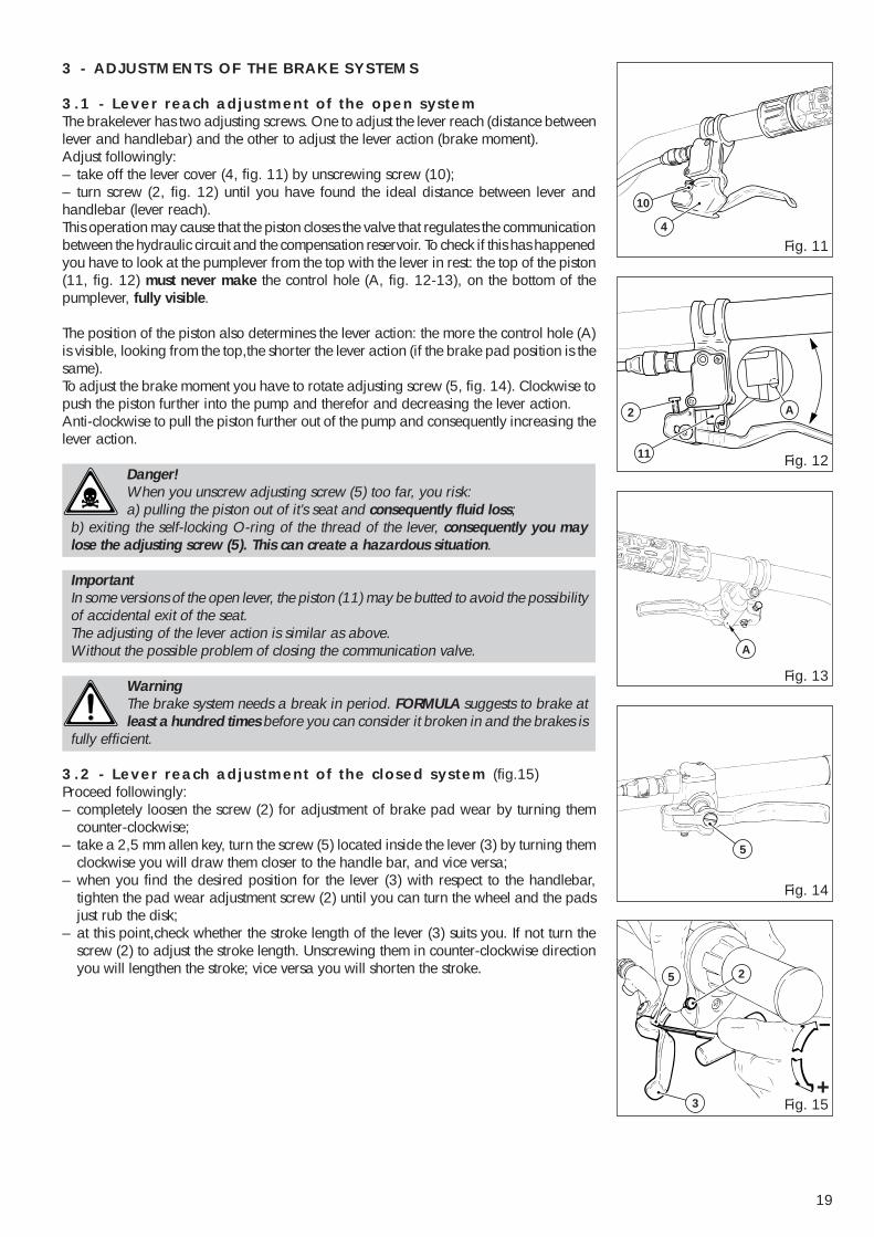
3 - ADJUSTMENTS OF THE BRAKE SYSTEMS
3.1 - Lever reach adjustment of the open systemThe brakelever has two adjusting screws. One to adjust the lever reach (distance betweenlever and handlebar) and the other to adjust the lever action (brake moment).Adjust followingly:– take off the lever cover (4, fig. 11) by unscrewing screw (10);– turn screw (2, fig. 12) until you have found the ideal distance between lever andhandlebar (lever reach).This operation may cause that the piston closes the valve that regulates the communicationbetween the hydraulic circuit and the compensation reservoir. To check if this has happenedyou have to look at the pumplever from the top with the lever in rest: the top of the piston(11, fig. 12) must never make the control hole (A, fig. 12-13), on the bottom of thepumplever, fully visible.
The position of the piston also determines the lever action: the more the control hole (A)is visible, looking from the top,the shorter the lever action (if the brake pad position is thesame).To adjust the brake moment you have to rotate adjusting screw (5, fig. 14). Clockwise topush the piston further into the pump and therefor and decreasing the lever action.Anti-clockwise to pull the piston further out of the pump and consequently increasing thelever action.
Danger!When you unscrew adjusting screw (5) too far, you risk:a) pulling the piston out of it’s seat and consequently fluid loss;
b) exiting the self-locking O-ring of the thread of the lever, consequently you maylose the adjusting screw (5). This can create a hazardous situation.
ImportantIn some versions of the open lever, the piston (11) may be butted to avoid the possibilityof accidental exit of the seat.The adjusting of the lever action is similar as above.Without the possible problem of closing the communication valve.
WarningThe brake system needs a break in period. FORMULA suggests to brake atleast a hundred times before you can consider it broken in and the brakes is
fully efficient.
3.2 - Lever reach adjustment of the closed system (fig.15)Proceed followingly:– completely loosen the screw (2) for adjustment of brake pad wear by turning them
counter-clockwise;– take a 2,5 mm allen key, turn the screw (5) located inside the lever (3) by turning them
clockwise you will draw them closer to the handle bar, and vice versa;– when you find the desired position for the lever (3) with respect to the handlebar,
tighten the pad wear adjustment screw (2) until you can turn the wheel and the padsjust rub the disk;
– at this point,check whether the stroke length of the lever (3) suits you. If not turn thescrew (2) to adjust the stroke length. Unscrewing them in counter-clockwise directionyou will lengthen the stroke; vice versa you will shorten the stroke.
20
18
17
7
8
9
16
14
12
15
12
13
Fig. 18
Fig. 17
Fig. 19
14
D
Fig. 16
Fig. 20
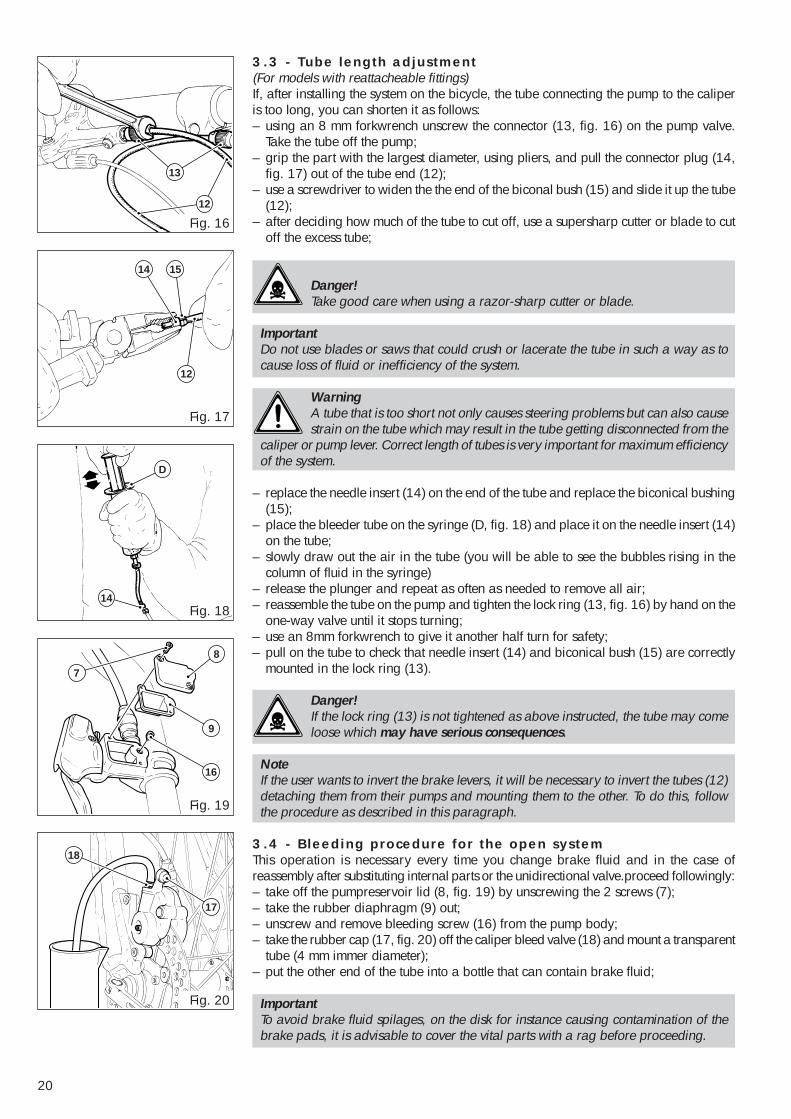
3.3 - Tube length adjustment(For models with reattacheable fittings)If, after installing the system on the bicycle, the tube connecting the pump to the caliperis too long, you can shorten it as follows:– using an 8 mm forkwrench unscrew the connector (13, fig. 16) on the pump valve.
Take the tube off the pump;– grip the part with the largest diameter, using pliers, and pull the connector plug (14,
fig. 17) out of the tube end (12);– use a screwdriver to widen the the end of the biconal bush (15) and slide it up the tube
(12);– after deciding how much of the tube to cut off, use a supersharp cutter or blade to cut
off the excess tube;
Danger!Take good care when using a razor-sharp cutter or blade.
ImportantDo not use blades or saws that could crush or lacerate the tube in such a way as tocause loss of fluid or inefficiency of the system.
WarningA tube that is too short not only causes steering problems but can also causestrain on the tube which may result in the tube getting disconnected from the
caliper or pump lever. Correct length of tubes is very important for maximum efficiencyof the system.
– replace the needle insert (14) on the end of the tube and replace the biconical bushing(15);
– place the bleeder tube on the syringe (D, fig. 18) and place it on the needle insert (14)on the tube;
– slowly draw out the air in the tube (you will be able to see the bubbles rising in thecolumn of fluid in the syringe)
– release the plunger and repeat as often as needed to remove all air;– reassemble the tube on the pump and tighten the lock ring (13, fig. 16) by hand on the
one-way valve until it stops turning;– use an 8mm forkwrench to give it another half turn for safety;– pull on the tube to check that needle insert (14) and biconical bush (15) are correctly
mounted in the lock ring (13).
Danger!If the lock ring (13) is not tightened as above instructed, the tube may comeloose which may have serious consequences.
NoteIf the user wants to invert the brake levers, it will be necessary to invert the tubes (12)detaching them from their pumps and mounting them to the other. To do this, followthe procedure as described in this paragraph.
3.4 - Bleeding procedure for the open systemThis operation is necessary every time you change brake fluid and in the case ofreassembly after substituting internal parts or the unidirectional valve.proceed followingly:– take off the pumpreservoir lid (8, fig. 19) by unscrewing the 2 screws (7);– take the rubber diaphragm (9) out;– unscrew and remove bleeding screw (16) from the pump body;– take the rubber cap (17, fig. 20) off the caliper bleed valve (18) and mount a transparent
tube (4 mm immer diameter);– put the other end of the tube into a bottle that can contain brake fluid;
ImportantTo avoid brake fluid spilages, on the disk for instance causing contamination of thebrake pads, it is advisable to cover the vital parts with a rag before proceeding.
21
Fig. 22
Fig. 23
Fig. 21
2
20
3
19
D
D
3
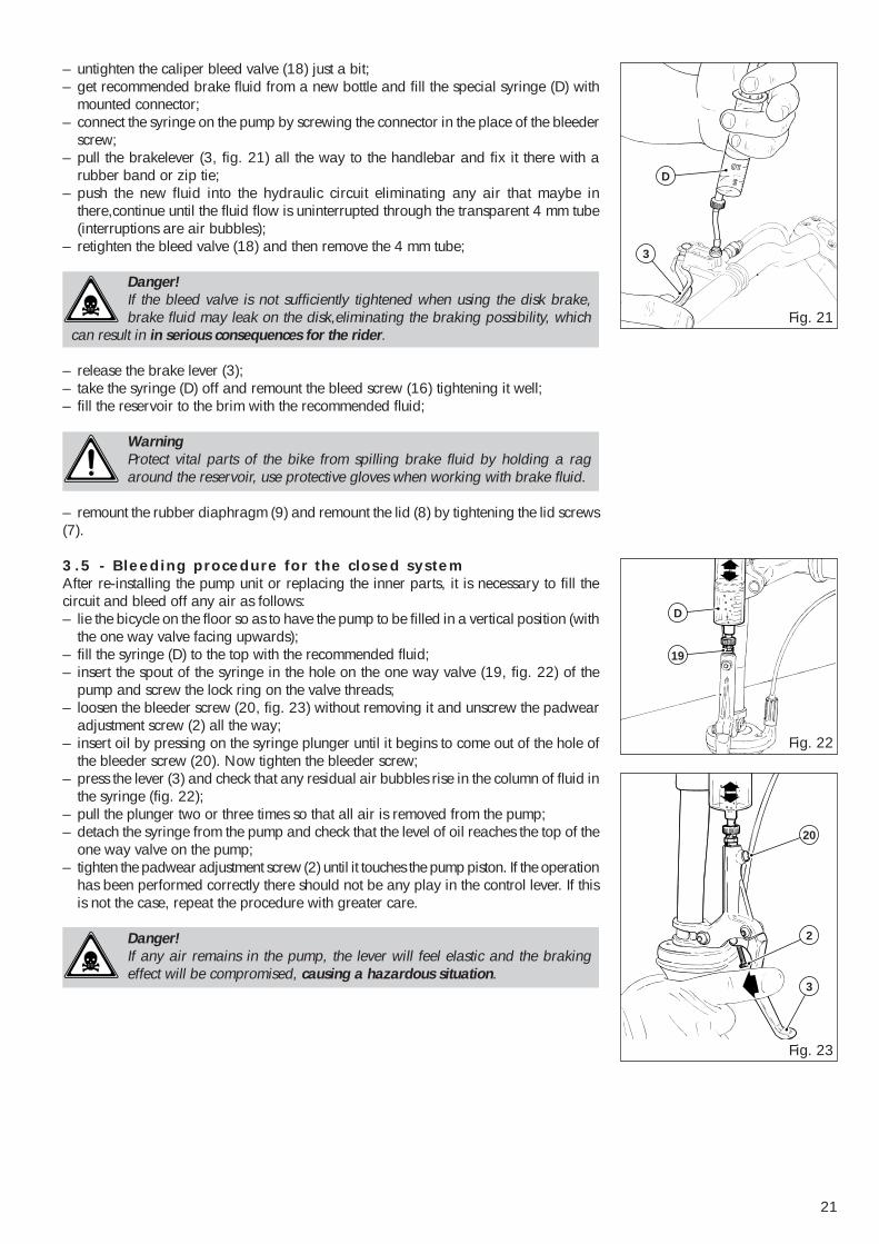
– untighten the caliper bleed valve (18) just a bit;– get recommended brake fluid from a new bottle and fill the special syringe (D) with
mounted connector;– connect the syringe on the pump by screwing the connector in the place of the bleeder
screw;– pull the brakelever (3, fig. 21) all the way to the handlebar and fix it there with a
rubber band or zip tie;– push the new fluid into the hydraulic circuit eliminating any air that maybe in
there,continue until the fluid flow is uninterrupted through the transparent 4 mm tube(interruptions are air bubbles);
– retighten the bleed valve (18) and then remove the 4 mm tube;
Danger!If the bleed valve is not sufficiently tightened when using the disk brake,brake fluid may leak on the disk,eliminating the braking possibility, which
can result in in serious consequences for the rider.
– release the brake lever (3);– take the syringe (D) off and remount the bleed screw (16) tightening it well;– fill the reservoir to the brim with the recommended fluid;
WarningProtect vital parts of the bike from spilling brake fluid by holding a ragaround the reservoir, use protective gloves when working with brake fluid.
– remount the rubber diaphragm (9) and remount the lid (8) by tightening the lid screws(7).
3.5 - Bleeding procedure for the closed systemAfter re-installing the pump unit or replacing the inner parts, it is necessary to fill thecircuit and bleed off any air as follows:– lie the bicycle on the floor so as to have the pump to be filled in a vertical position (with
the one way valve facing upwards);– fill the syringe (D) to the top with the recommended fluid;– insert the spout of the syringe in the hole on the one way valve (19, fig. 22) of the
pump and screw the lock ring on the valve threads;– loosen the bleeder screw (20, fig. 23) without removing it and unscrew the padwear
adjustment screw (2) all the way;– insert oil by pressing on the syringe plunger until it begins to come out of the hole of
the bleeder screw (20). Now tighten the bleeder screw;– press the lever (3) and check that any residual air bubbles rise in the column of fluid in
the syringe (fig. 22);– pull the plunger two or three times so that all air is removed from the pump;– detach the syringe from the pump and check that the level of oil reaches the top of the
one way valve on the pump;– tighten the padwear adjustment screw (2) until it touches the pump piston. If the operation
has been performed correctly there should not be any play in the control lever. If thisis not the case, repeat the procedure with greater care.
Danger!If any air remains in the pump, the lever will feel elastic and the brakingeffect will be compromised, causing a hazardous situation.
22
D
19
12
13
14
12
15
Fig. 26
Fig. 24
Fig. 27
D
14
15 12
1817
13
Fig. 25
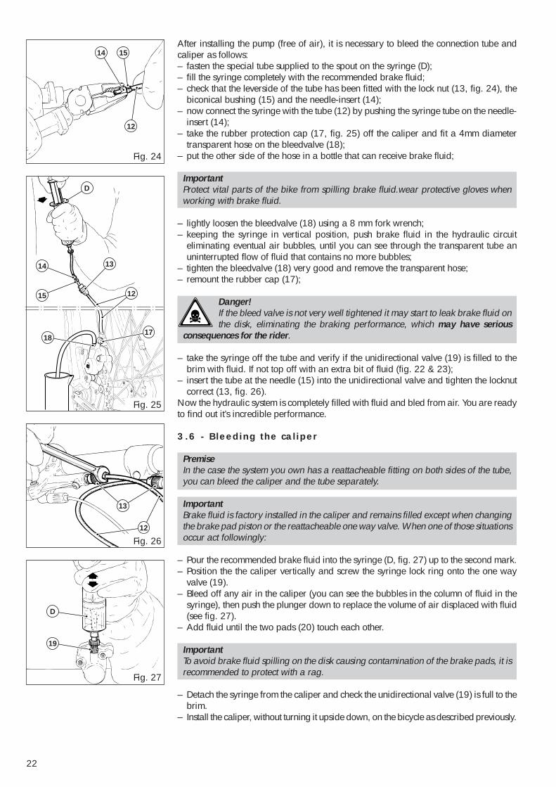
After installing the pump (free of air), it is necessary to bleed the connection tube andcaliper as follows:– fasten the special tube supplied to the spout on the syringe (D);– fill the syringe completely with the recommended brake fluid;– check that the leverside of the tube has been fitted with the lock nut (13, fig. 24), the
biconical bushing (15) and the needle-insert (14);– now connect the syringe with the tube (12) by pushing the syringe tube on the needle-
insert (14);– take the rubber protection cap (17, fig. 25) off the caliper and fit a 4mm diameter
transparent hose on the bleedvalve (18);– put the other side of the hose in a bottle that can receive brake fluid;
ImportantProtect vital parts of the bike from spilling brake fluid.wear protective gloves whenworking with brake fluid.
– lightly loosen the bleedvalve (18) using a 8 mm fork wrench;– keeping the syringe in vertical position, push brake fluid in the hydraulic circuit
eliminating eventual air bubbles, until you can see through the transparent tube anuninterrupted flow of fluid that contains no more bubbles;
– tighten the bleedvalve (18) very good and remove the transparent hose;– remount the rubber cap (17);
Danger!If the bleed valve is not very well tightened it may start to leak brake fluid onthe disk, eliminating the braking performance, which may have serious
consequences for the rider.
– take the syringe off the tube and verify if the unidirectional valve (19) is filled to thebrim with fluid. If not top off with an extra bit of fluid (fig. 22 & 23);
– insert the tube at the needle (15) into the unidirectional valve and tighten the locknutcorrect (13, fig. 26).
Now the hydraulic system is completely filled with fluid and bled from air. You are readyto find out it’s incredible performance.
3.6 - Bleeding the caliper
PremiseIn the case the system you own has a reattacheable fitting on both sides of the tube,you can bleed the caliper and the tube separately.
ImportantBrake fluid is factory installed in the caliper and remains filled except when changingthe brake pad piston or the reattacheable one way valve. When one of those situationsoccur act followingly:
– Pour the recommended brake fluid into the syringe (D, fig. 27) up to the second mark.– Position the the caliper vertically and screw the syringe lock ring onto the one way
valve (19).– Bleed off any air in the caliper (you can see the bubbles in the column of fluid in the
syringe), then push the plunger down to replace the volume of air displaced with fluid(see fig. 27).
– Add fluid until the two pads (20) touch each other.
ImportantTo avoid brake fluid spilling on the disk causing contamination of the brake pads, it isrecommended to protect with a rag.
– Detach the syringe from the caliper and check the unidirectional valve (19) is full to thebrim.
– Install the caliper, without turning it upside down, on the bicycle as described previously.
23
D
13
15
12
14
12
13
5
5
20
21
Fig. 29
Fig. 31
Fig. 28
Fig. 30
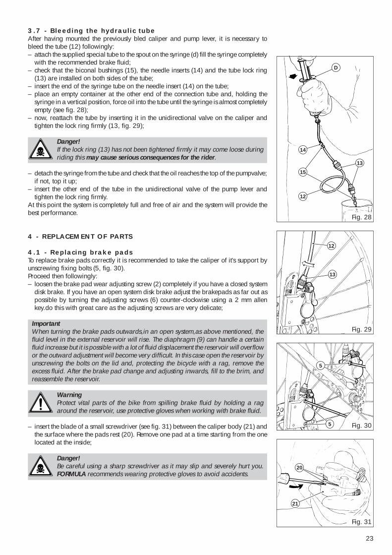
3.7 - Bleeding the hydraulic tubeAfter having mounted the previously bled caliper and pump lever, it is necessary tobleed the tube (12) followingly:– attach the supplied special tube to the spout on the syringe (d) fill the syringe completely
with the recommended brake fluid;– check that the biconal bushings (15), the needle inserts (14) and the tube lock ring
(13) are installed on both sides of the tube;– insert the end of the syringe tube on the needle insert (14) on the tube;– place an empty container at the other end of the connection tube and, holding the
syringe in a vertical position, force oil into the tube until the syringe is almost completelyempty (see fig. 28);
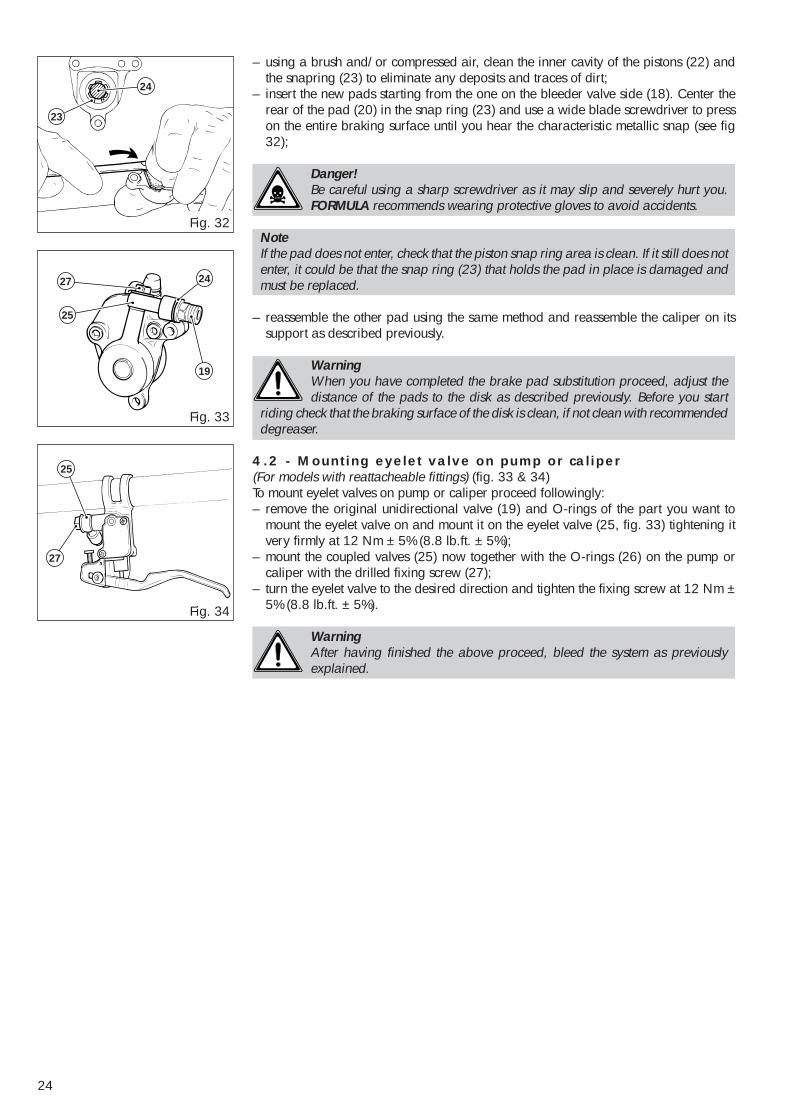
– now, reattach the tube by inserting it in the unidirectional valve on the caliper andtighten the lock ring firmly (13, fig. 29);
Danger!If the lock ring (13) has not been tightened firmly it may come loose duringriding this may cause serious consequences for the rider.
– detach the syringe from the tube and check that the oil reaches the top of the pumpvalve;if not, top it up;
– insert the other end of the tube in the unidirectional valve of the pump lever andtighten the lock ring firmly.
At this point the system is completely full and free of air and the system will provide thebest performance.
4 - REPLACEMENT OF PARTS
4.1 - Replacing brake padsTo replace brake pads correctly it is recommended to take the caliper of it’s support byunscrewing fixing bolts (5, fig. 30).Proceed then followingly:– loosen the brake pad wear adjusting screw (2) completely if you have a closed system
disk brake. If you have an open system disk brake adjust the brakepads as far out aspossible by turning the adjusting screws (6) counter-clockwise using a 2 mm allenkey.do this with great care as the adjusting screws are very delicate;
ImportantWhen turning the brake pads outwards,in an open system,as above mentioned, thefluid level in the external reservoir will rise. The diaphragm (9) can handle a certainfluid increase but it is possible with a lot of fluid displacement the reservoir will overflowor the outward adjustment will become very difficult. In this case open the reservoir byunscrewing the bolts on the lid and, protecting the bicycle with a rag, remove theexcess fluid. After the brake pad change and adjusting inwards, fill to the brim, andreassemble the reservoir.
WarningProtect vital parts of the bike from spilling brake fluid by holding a ragaround the reservoir, use protective gloves when working with brake fluid.
– insert the blade of a small screwdriver (see fig. 31) between the caliper body (21) andthe surface where the pads rest (20). Remove one pad at a time starting from the onelocated at the inside;
Danger!Be careful using a sharp screwdriver as it may slip and severely hurt you.FORMULA recommends wearing protective gloves to avoid accidents.
24
27
25
25
27
19
24
Fig. 33
Fig. 34
24
23
Fig. 32
– using a brush and/or compressed air, clean the inner cavity of the pistons (22) andthe snapring (23) to eliminate any deposits and traces of dirt;
– insert the new pads starting from the one on the bleeder valve side (18). Center therear of the pad (20) in the snap ring (23) and use a wide blade screwdriver to presson the entire braking surface until you hear the characteristic metallic snap (see fig32);
Danger!Be careful using a sharp screwdriver as it may slip and severely hurt you.FORMULA recommends wearing protective gloves to avoid accidents.
NoteIf the pad does not enter, check that the piston snap ring area is clean. If it still does notenter, it could be that the snap ring (23) that holds the pad in place is damaged andmust be replaced.
– reassemble the other pad using the same method and reassemble the caliper on itssupport as described previously.
WarningWhen you have completed the brake pad substitution proceed, adjust thedistance of the pads to the disk as described previously. Before you start
riding check that the braking surface of the disk is clean, if not clean with recommendeddegreaser.
4.2 - Mounting eyelet valve on pump or caliper(For models with reattacheable fittings) (fig. 33 & 34)To mount eyelet valves on pump or caliper proceed followingly:– remove the original unidirectional valve (19) and O-rings of the part you want to
mount the eyelet valve on and mount it on the eyelet valve (25, fig. 33) tightening itvery firmly at 12 Nm ± 5% (8.8 lb.ft. ± 5%);
– mount the coupled valves (25) now together with the O-rings (26) on the pump orcaliper with the drilled fixing screw (27);
– turn the eyelet valve to the desired direction and tighten the fixing screw at 12 Nm ±5% (8.8 lb.ft. ± 5%).
WarningAfter having finished the above proceed, bleed the system as previouslyexplained.


![Case Report Syndrome of Inappropriate Antidiuretic Hormone ... · syndrome of inappropriate antidiuretic hormone secretion (SIADH) is the most frequent cause of hyponatremia[ ].](https://img.pdfslide.net/doc/110x75/60a8e8a8c280c12e363724e7/case-report-syndrome-of-inappropriate-antidiuretic-hormone-syndrome-of-inappropriate.jpg)