Embed Size (px)
Citation preview

17
Reconfigurable Antennas of Wide Tuning Ranges and Controllable Selectivity
Using Matching Networks
Chin-Lung Yang and Chieh-Sen Li Department of Electrical Engineering, National Cheng Kung University
Taiwan
1. Introduction
In this chapter, a novel design method was proposed for reconfigurable antennas, independent of the geometries and the dimensions of the antennas, providing wide tuning ranges and controllable selectivity. A simple, unspecified S-UWB antenna can be attached to a feeding network to form one integrated selective and reconfigurable antenna. Through the design of tunable wideband matching network, a simple modified ultra-wide band (UWB) antenna can be reconfigurable and re-operated in different bands over a wide of ranges. Based on UWB antennas with proper T- or π-shaped matching network designed in frequency domain, the receiving antennas can be switched to specific bands or even multiple bands continuously. Most of the multiband antennas need complicated approaches to control bandwidths and lack of tuning flexibility. However, the design principles and the controlling mechanism based on microwave circuit theorems are relatively simple, so different fractional bandwidths from 5% to 20% can be feasibly implemented in our proposed architecture. Therefore, the parameters for the antenna operation bands and bandwidths can be calculated and estimated in a straight forward manner. The L-, T- and π-network are chosen for examples to demonstrate the performance in simulation and in implementation. The simulation results show that the proposed antenna can cover from 1.8 GHz to 11.5 GHz with bandwidth ~300 MHz. Replacing the L- type with a T-type or π-type network which gives one more variable freedom to achieve high selective reconfigurable antenna of 80 MHz bandwidth. By utilizing special designed tuning inductors, the antenna bandwidth can be further controllable. The simulation results show that this proposed antenna can switch to 1.8, 2.45, and 3.5 GHz with bandwidths from 80 to 400 MHz. The proposed antenna architecture provides a reconfigurable RF front end for transmission and reception. Such high flexibility can enable antennas to operate in varying environments for biomedical applications and different bands and thereby, make antennas applicable to wireless body area network (WBAN) as well as multi-mode/multi-band commercial applications. The novel circuitry antenna (modified UWB antenna combining with feed matching components) approach expands the flexibility and the bandwidth for multiband communication systems in a simple implementation. Reconfigurable multi-band antennas have drawn attentions for modern heterogeneous communication systems, such as antennas for quad-band cellphones, Software-defined
www.intechopen.com

Ultra Wideband Communications: Novel Trends – Antennas and Propagation 336
radio (SDR), and Cognitive Radio (CR) which even requires antennas to cover multiple bands or operate at flexible frequency ranges. New technologies, such as micro-electromechanical systems (MEMS), expand the reconfigurable design varieties [Weedon 1999]. In this chapter, a novel concept of ‘impedance matching in frequency domain’ (as Figure 1) is proposed to make the design of reconfigurable antenna straight forward and can be implemented in low cost, simple circuits. This method is different from other methods based on the geometric modification which is developed to induce multiple resonant radiating frequencies. For example, the tri-band antenna in constructed based on a patch antenna design [Guo 2008][Sheta 2008] which peels off some slots or connect some discrete patches to create other effective current path and enable higher/lower radiation frequencies. Most of the designs modify the geometries and the dimensions of the antennas for multiband antennas. Moreover, this seems similar to but is totally different from filter-based reconfiguration. The most obvious feature is that it is not easy for tunable filters to design and implement, nor is its bandwidth tuning easily. In our proposed architecture, merely three components can fulfill reconfigurable antennas of wide tuning ranges and controllable selectivity by using matching networks. A tunable filter provides an excellent selection to implement tunable bands, but tunable
filter are usually difficult to design and control. The comparison is listed in Table 1. To
achieve tunable capability, our proposed architecture has advantage of very wide tuning
range, flexible control, and easy analysis. There are currently many fabrication technologies
[Hoarau 2008]. Hybrid circuits using discrete components such as diodes and SMD
components are easier to make and design for prototypes in commercial bands to verify
concepts, and these components may be further integrated in compact size in the future. The
main design issues of tunable matching network include applicable frequency ranges,
impedance tuner dynamic range, control methods, linearity, size and losses. Concerning the
tunable frequency range, a high selectivity usually comes along with a limited tunable
range. However, this problem can be easily overcome in our proposed architecture. The four
main investigative objectives in this chapter are operating frequency ranges, other undesired
bands suppression, the use of one single component to fulfill the tunable function, and
energy loss reduction.
Fig. 1. The architecture of the reconfigurable multiband antennas.
In this chapter, by expanding the concept of “analog antenna” and ‘impedance matching in frequency domain’ [Yang 2009], the design of reconfigurable multimode and multiband
Continuous
Tunable
Narrow
Bands
Tunable Matching Network
in Frequency Domain
-10dB
1.8-3.6GHz
S11
Tunable
Inductor
www.intechopen.com

Reconfigurable Antennas of Wide Tuning Ranges and Controllable Selectivity Using Matching Networks 337
antennas is developed in a straight forward manner and also implemented in low cost, simple circuits. The “analog antenna” in this chapter means that one un-designed antenna combined with a small circuitry to enhance or expand the original function or specification. For this proposed antenna, a frequency-tuning matching network which may have different architectures is added. The illustration of the reconfigurable multiband analog antenna is shown in Figure 1. The matching networks may have traditional structures, such as L/T/π-shaped matching network and cascaded/mixed matching network with RF switches or varactors to tune the impedance of the semi-ultra wide band (S-UWB) antennas in specific bands, which are easy to design and implement instead of using wide-band reconfigurable and sharp filters. Therefore, multiband can be achieved while covered range is still wide.
Tuning Types Tuning
Analysis Impedance Matching
Antenna Patterns Range Control
Modified Geometry Broad +++ Middle Yes Yes
Tunable Filter Narrow + Hard No No
This Design VeryWide ++++ Easy Yes No
Table 1. Typical Comparison for Frequency Tuning Functions
Moreover, to add on extra specific bands needs not to re-design the whole antenna, but to modify the matching network parameters. In this chapter, we demonstrate this concept in tri-band using lump elements for the prototypes. ADS simulations are performed to predict those multiple bands and procedures of tuning these practical lumped component values are also developed and will be addressed later. The proposed switchable multi-band antennas have the features of utilizing semi-UWB antennas, operating at multiple bands, re-configuration, and controllable bandwidth. However, these multiple bands will not occur at the sample time, each one will function as the communication system switches to their mode and frequency.
2. System description and design principles
This system includes three parts: a semi-UWB antenna, frequency-tuning matching network,
and the controlling unit. The system block is shown in Figure. 2. From this figure, not only
the components are variable, but also some switches are placed at the joins of the matching
network to modify its own architectures. Two major steps for such proposed multiband
antennas include S-UWB antenna design and matching network design. The controlling unit
is assumed to be pre-assigned to turn on different modes. Each step is easy and quick, so the
development and optimization process can and be improved significantly. In this chapter, a
tri-band system will be demonstrated and operated at 1.8 GHz, 2.45 GHz, and 3.5 GHz,
which are common for cellphone frequency band (GSM), ISM/WLAN band, and WiMAX
band in some countries, respectively.
Taking loss and design complexity into consideration, we use as few components as possible
to simplify mathematical analysis and induce less loss. In contrast to L-type network which
has limited impedance dynamic ranges to match and lack of freedom for controllable Q
value, T-type and π-type networks are commonly confined to carry out high selectivity and
www.intechopen.com

Ultra Wideband Communications: Novel Trends – Antennas and Propagation 338
a wide scope of tunable impedance network due to that the extra degree of freedom can
further be used to control the bandwidth. We chose a T-type (C-L-C) network that includes
two serial capacitors and a parallel inductor between them shown as Figure 3. The central
shunt part is the variable inductor L, implemented by a fixed L and a varactor.
Fig. 2. System diagram of the band-switchable antennas.
Fig. 3. Equivalent circuit of the tunable matching network and S-UWB antenna with control bias voltages VBIAS, series capacitor shunt inductor L and varactor
There are two major steps to design the proposed reconfigurable antenna, including S-UWB
antenna design and tunable matching network design. Each step is quite straight forward
and thereby improves significantly the development and optimization process.
2.1 Design for semi-UWB antenna Instead of designing a tri-band antenna directly to cover these bands simultaneously, a semi-UWB antenna is desired to cover these bands. A semi-UWB antenna means similar to UWB antenna, but it does not guarantee all the return loss below -10 dB over its operation bandwidth. Popular or compact UWB antenna designs can be referred and guided [Wong 2005] [Peyrot-Solis 2005]; however, it is not necessary to optimize all the dimensions to have
www.intechopen.com

Reconfigurable Antennas of Wide Tuning Ranges and Controllable Selectivity Using Matching Networks 339
ultra wide band response, like one real UWB antenna does (so we called such antennas as S-UWB antennas). On the contrary, radiating over semi-wide bands is sufficient. Therefore, antenna design and procedure for tradeoff between the bandwidth, gain, and efficiency can be reduced substantially. We randomly pick up two kinds of antennas to demonstrate our concepts and design. One is circle-shaped, and the other is beveled-shaped. A circle-shaped antenna on a 1.6-mm FR4 (┝r = 4.3, loss tangent ├ = 0.015) substrate is chosen as one of the options for demonstration in this chapter. Its dimension is determined from HFSS simulations. The relevant dimensions of circular-shape antennas are [r/d/g/wf] = 21.3/1/10/2.7 mm; [L1/L2/W] = 62/19/64 mm. The dimension of the beveled-shaped one is determined from HFSS simulations and listed in below. The geometry and dimension is shown in Figure 4 and 5. Surely other shapes and UWB-like antennas can be possible to apply following the same design principles. The return loss is measured and shown in Figure 4 and 5. From the result of the measured S11, we found this S-UWB antenna performs relatively poorly at 4-5 GHz, but we need not to tune its dimensions and feeding structure to optimize this antenna. These performances at desired bands will be considered with matching network altogether.
Fig. 4. Beveled-shaped S-UWB antenna and S11 plot from the HFSS simulation.
Fig. 5. The circle-shaped S-UWB antenna and S11 plot from the HFSS simulation.
2.2 Design for frequency-tuning matching network The L-C type matching network, which is optional, is chosen to adapt the impedance to match at the desired frequency. Therefore, the overall antenna with the matching network
1 2 3 4 5 6
-60
-50
-40
-30
-20
-10
0
S1
1 (
dB
)
Frequency (GHz)
S-UWB Antenna Measurement
www.intechopen.com
Ultra Wideband Communications: Novel Trends – Antennas and Propagation 340
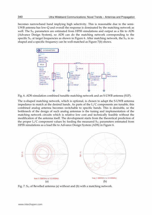
becomes narrowband band implying high selectivity. This is reasonable due to the semi-UWB antenna has low-Q and overall the response is dominated by the matching network as well. The S11 parameters are estimated from HFSS simulations and output as a file to ADS (Advance Design System), so ADS can do the matching network corresponding to the specific S11 at target frequencies as shown in Figure 6. After matching network, the S11 is re-shaped and a specific frequency can be well-matched as Figure 7(b) shows.
Fig. 6. ADS simulation combined tunable matching network and an S-UWB antenna (S1P).
The π-shaped matching network, which is optional, is chosen to adapt the S-UWB antenna impedance to match at the desired bands. As parts of the L/C components are tunable, this combined analog antenna becomes switchable to specific bands. This is desirable, so the bottleneck of the design of such analog antennas is the tuning and implementation of the matching network circuits which is relative low cost and technically feasible without the modification of the antenna itself. The development starts from the theoretical prediction of the proper L/C component values by feeding the measured S11 parameters estimated from HFSS simulations as a load file to Advance Design System (ADS) in Figure 6.
(a) (b)
Fig. 7. S11 of Bevelled antenna (a) without and (b) with a matching network.
freq (1.500GHz to 12.00GHz)
S(1
,1)
freq (1.500GHz to 12.00GHz)
S(1
,1)
www.intechopen.com

Reconfigurable Antennas of Wide Tuning Ranges and Controllable Selectivity Using Matching Networks 341
The procedure of determining the component values is shown as below. This is well-established and makes the development of the multiband based on our proposed architecture relatively easy. We further apply a practical C model (S parameters are measured) into the ADS for a fine tuning in the frequency band to reduce the errors of the implementation. Our goal is to set the S-UWB antenna to have good matching (Zin (ωc) = Rs) at the operation band centered at ωc, which means Γin (ωc) = 0; meanwhile we also estimate the bandwidth by circuit Q values. We set a redundant resistance (RV) as the mediate step to calculate matching as two cascaded L-shaped networks (shown in Figure 8).
s
1
v
Q 1R
R (1)
2
v L
1Q 1
-GR (2)
The unloaded Q of the cascaded network Q =max (|Q1|, |Q1|), and the bandwidth can be determined by 2/|Q|. Applying (1) and (2) into ADS, Table 2 lists the component values of the matching network for this proposed tri-band antenna.
Fig. 8. The mediate step reconfigurable multiband analog antennas.
Frequency (GHz) C1 (pF) L2 (nH) C3 (pF)
Band I 1.8 3.858 2.590 6.545
Band II 2.4 3.760 2.972 5.250
Band III 3.5 2.490 1.150 5.800
Table 2. L-C values of the matching network for tri-band.
According to those desired L/C values based on specific Q values, ADS can fulfill the simulations of this analog antenna at target bands. After π-shaped matching network, the simulated S11 of this circular S-UWB antenna is re-shaped to a narrow band antenna and in this specific band, S11 can be well-matched as Figure 9 shows. The original S-UWB antenna covers from 2 to 4.5 GHz well. Using the band II parameters, the 2.45 GHz band is will matched, while others are rejected and this proposed antenna functions as a high selective antenna. After the proper L/C values are found, we need further to calibrate the practical values and the influences of the switches (GaAs SPDT, model no. SKY13306-313LF) on the
www.intechopen.com

Ultra Wideband Communications: Novel Trends – Antennas and Propagation 342
matching performance for the implementation which will be discussed in the later section. The switches are modeled as loss transmission lines unless they are RF-MEMS switches which provide extremely low loss and huge isolation.
a) b)
Fig. 9. Measured S11 smith chart of circular S-UWB antenna: (a) without and (b) with a matching network tuned to 2.45 GHz.
3. Analysis and simulations for matching network
A complete impedance matching theory and numerical analysis are well-established [Thompson 1996][Schmidt 2007]. However, there exists a high complexity and practical performance loss after considering the parasitic effects, fabrication errors and self-resonant frequency from components in realistic operation. The traditional matching network encounters unavoidable tolerance errors from capacitance and inductance resulting in a frequency deviation away from desired frequency. In this chapter, not only do we have to solve the matching problem, but furthermore, we also eliminate the frequency deviation due to the drifting of capacitance and inductance components. The π- and T-type networks themselves can be designed with a desired Q value. However, one common problem for the wideband matching is that uniqueness of the matched bands, which means other undesired bands might happen to be matched unintentionally. Moreover, an unfavorable drawback occurs when using a varactor which needs an additional biased from microstrip line, resulting in discontinuity and parasitic effects. All of these factors above shall be taken into consideration seriously to increase the selectivity and performance. These issues will be addressed in following sections to further improve a highly selective matching network with high Q value and with a continuously smooth tuning effect. These practical factors are also taken into account for simulation, especially for the models of precise values in high frequency.
3.1 Analysis for High-Q tunable S-UWB antennas One of the unique merits for UWB antennas to design such tunable matching network is that its input impedance already resembles 50 Ω (ZANT≅Zo) within a very broad bandwidth. Based on this characteristic, 50 Ω terminals are used at both ports of the matching network as the preliminary design to determine the appropriate values of C1, C2, and L, and to
0.2 0.5 1.0 2.0 5.0
-0.2j
0.2j
-0.5j
0.5j
-1.0j
1.0j
-2.0j
2.0j
-5.0j
5.0j
www.intechopen.com

Reconfigurable Antennas of Wide Tuning Ranges and Controllable Selectivity Using Matching Networks 343
reduce the number of variables from antenna impedances. We chose two fixed similar low-value capacitors C1 and C2 for two serial components of T-type network in Figure 3. The simulation and implementation has proved that this nearly 50 Ω assumption does not affect the accuracy of performance evaluation. The high selectivity can be explained by tracing the trajectory of the impedance. By using the first series low-value capacitor C2, original antenna impedance, ZANT, will be moved to the right half of Smith chart (Z2, high capacitive reactance) along the unit circuit, and the end point intersects with high Q circle (as shown in Figure 10). The target matching frequency is set through a ‘single’ variable inductor L and the impedance becomes Z1. Then, by applying the up-down symmetrical nature of Smith chart, a second series capacitor C1 of the same value, C1=C2=C, pulls back from impedance Z1 to the center point Zo = 50 Ω and completes the impedance matching at the desired frequency. The tuning antenna is operated at this band thereby. As the large C1 and C2 are applied, a low selectivity can be fulfilled theoretically as shown in the right part of Figure 10(b).
Fig. 10. Matching analysis on Smith chart with (a) High Q; (b) Low Q value.
An analytic formula for calculating the unknown inductance can be obtained as below, so the unknown inductance value L can be determined according to tunable matching frequency. T-type network impedance matching function can be observed from Figure 3 and is given as equation (3).
11
0
2 1
Ant
total
j j jZ Z
C L C
(3)
Applying the conditions of ZANT≅Zo, C1= C2=C (constant), and the target frequency ωtarget, and simplifying the equation, we get the equation (4) to obtain the inductor Ltotal.
2
0 2
1 1
2total
taget
L CZC
(4)
www.intechopen.com

Ultra Wideband Communications: Novel Trends – Antennas and Propagation 344
where Ltotal is controlled by a vacator series with a fixed L to achieve well-matched at the frequency ωtarget, and continuous tuning can be fulfilled by using a varactor, instead of discrete switching. We must apply the actual component values before it can comply with the predicted target frequency and find the precise frequency tuning ranges. Through basic thru-reflect-line (TRL) calibration technique, the values of the capacitance, the inductance and the parasitic impedance can be obtained precisely. After we calculated the theoretical matching inductance, Ltotal, and the corresponding cascaded capacitance, Cvaractor, the bias voltage value for the required capacitance can be
determined from the varactor C-V curve we measured. Therefore, the variable inductor can be modeled with a proper varactor model which can be referenced in [Stauffer 2003]. The varying range of inductance is dominated by the varactor. This factor has thus determined the tunable ranges. In this chapter, a preliminary validation around 3 GHz is verified. The
components are not optimized intentionally yet. Due to SMD component tolerance errors, the actual implemented operation frequency might be deviated. From the deviation status, the inductance differences are calibrated, and then the frequency deviation is compensated
by correcting the bias voltage slightly to achieve the precise target frequency.
4. Implementation and experiment setup
To implement the proposed wide tuning antenna, three major parts are fabricated including an S-UWB antenna, a tunable matching network, and a controlling circuit. S-UWB antenna is fabricated without optimized fully-qualified performance. A circular-shaped antenna on
FR4 (┝r = 4.3 and loss tangent ├=0.015) substrate of 1.6 mm thickness is chosen and fabricated for demonstration as a simple design with an available wideband. Of course, other wideband antennas in different shapes are possible options. The relevant dimensions
of S-UWB antenna are [r/d/g/wf] = 21.3/1/10/2.7 mm and [L1/L2/W] = 62/19/64 mm. Those long transmission lines are extended for measurement and can be removed. The ‘π’-shaped matching network is very small and attached at the interface of the antenna and RF front end. The frequency-tuning matching network is separated for the test purpose and it is
feasible to fabricate nearly the antenna. The whole band-switchable tri-band antenna (analog antenna) and the transmission test is shown in Figure 11. Tri-band operation will be validated using Agilent NWA 8753E. Furthermore, we setup a UWB ridged horn to test path
loss S21 using the proposed antenna. The orientation setup is based on the original the directivity of the S-UWB antenna. The whole integrated reconfigurable antenna is shown in Figure 11, including the
fabricated tunable matching network on Roger substrate (R04003C, ┝r = 3.55, loss tan├=
0.0021) of 32 mil (0.81 mm) thickness. The component values are C1 =C2 = 0.6 pF, L2 = 4.7
nH, and Lchoke = 7.8 nH (for bias voltage input). The model number of GaAs hyperabrupt
tuning varactor is MGV-125-23-E28, with a useable capacitance from 0.3 pF to 4 pF. The Q
factor of the varactor is 3000, and its series resistance is about 1 Ω. The controlled circuitry
is made by the micro-processor 89C51 to set a proper bias voltage on varactor through a
DAC and an OP-Amplifier. The controlling module can be miniature using ASIC
technologies in the future. The S11 of the reconfigurable antenna can be measured with the
network analyzer Agilent N9020A. One double ridged UWB horn antenna (1 GHz ~ 18
GHz) is placed at a distance of 60 cm as the far field region to test the reception
performance (S21) of the tunable antenna.
www.intechopen.com

Reconfigurable Antennas of Wide Tuning Ranges and Controllable Selectivity Using Matching Networks 345
Fig. 11. The implemented reconfigurable S-UWB antenna attached with matching network.
5. Results and discussion
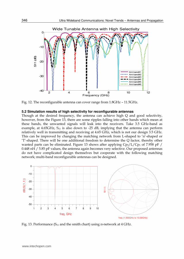
5.1 Simulation results of wide range for reconfigurable antennas Table 3 shows the simulation results of antenna impedances; therefore, series inductor L and
parallel inductor C is chosen correspondingly. Then, the W-USB antenna becomes a
narrowband one and selects at frequencies 1.8, 2.4, 3.5, 5.8, 9, and 11.5 GHz as shown in
Figure 12. This implies the proposed techniques can provide a very broad tunable range,
which is very significant. The ratio is 11.5/1.8 (~640%). In practice, the loss of the realistic
matching network should be taken into account, so this is one of the reasons why S-UWB
antennas are chosen so that the matching component can be realistic. For example, an
antenna whose impedance contains a low resistive part and very high reactance is not good
for matching implementation. Of course, while considering the practical parasitic effects, the
tuning ratio will reduce, but it is still wide enough and will be shown in measurement.
Frequency(GHz) 1.8 2.4 3.5 5.8 9 11.5
Zantenna(Ω) 15.678 +
j0.93 39.05 + j13.52
17.12 + j21.11
15.03 + j13.63
33.87 – j30.55
26.43 – j7.95
Parallel Cap, C1 (pF) 1.969 0.474 0.119 0.255 0.953 0.145
Series Ind, L2 (nH) 2.617 0.702 1.261 0.837 0.244 0.228
Table 3. Designing L-C values for specific frequencies.
www.intechopen.com
Ultra Wideband Communications: Novel Trends – Antennas and Propagation 346
Fig. 12. The reconfigurable antenna can cover range from 1.8GHz – 11.5GHz.
5.2 Simulation results of high selectivity for reconfigurable antennas Though at the desired frequency, the antenna can achieve high Q and good selectivity, however, from the Figure 13, there are some ripples falling into other bands which mean at these bands, the unwanted signals will leak into the receivers. Take 3.5 GHz-band as example, at 4.65GHz, S11 is also down to -25 dB, implying that the antenna can perform relatively well in transmitting and receiving at 4.65 GHz, which is not our design 3.5 GHz. This can be improved by changing the matching network from L-shaped to ‘π’-shaped or ‘T’-shaped. There will be one additional freedom to determine the Q factor, thereby other wanted parts can be eliminated. Figure 13 shows after applying Cp2/L/Cp1 of 7.958 pF / 0.448 nH / 5.85 pF values, the antenna again becomes very selective. Our proposed antennas do not have complicated design themselves but cooperate with the following matching network; multi-band reconfigurable antennas can be designed.
Fig. 13. Performance (S11 and the smith chart) using π-network at 4 GHz.
2 4 6 8 10 12-40
-30
-20
-10
0
Frequency (GHz)
S11 (dB)
Wide Tunable Antenna with High Selectivity
Ant-band#1
Ant-band#2
Ant-band#3Ant-band#4
Ant-band#5
Ant-band#6
2 3 4 5 6 7 8 91 10
-40
-30
-20
-10
-50
0
freq, GHz
dB
(S(1
,1))
freq (1.500GHz to 10.00GHz)
S(1
,1)
www.intechopen.com

Reconfigurable Antennas of Wide Tuning Ranges and Controllable Selectivity Using Matching Networks 347
5.3 Measurement of fabricat ed tri-band antennas Due to the manufacture variation of the lump elements, those calculated L/C values are tested separately to obtain its practical S-parameter model (S1P). After re-tuning according to these manufactured parameters and considering those transmission and switch influences carefully, the performance of the proposed tri-band antenna is shown in Figure 14. The dashed, solid, and dotted lines correspond to the ADS simulated results in different bands. Furthermore, this antenna keeps the flexibility of the tuning to the three bands without replacement of the S-UWB but the matching network components. Furthermore, if we add one set of the C1/L2/C3 (=5.06pF/ 0.397nH/ 4.11pF) lump element values, we can expand this antenna into a quad-band antenna. This implies this fabricated antenna can be extended to a multiband antenna (more than four bands) easily with extremely low cost. However, close bands need extremely high-Q and precise components to isolate and it is not fulfilled in this work.
1.5 2.0 2.5 3.0 3.5 4.0
-40
-30
-20
-10
0
S1
1 (
dB
)
Frequency (GHz)
Band3
Band2
Band1
Switchable Tri-band Antenna
Fig. 14. S11 of the measured tri-band antenna.
5.4 Measurement of controllable bandwidth As we mention in introduction, most of the multiband antenna is fixed and can be
optimized the performance for their specific bands; however, it is relatively complicated to
control the bandwidth. This may be useful for the adaptively date rate system for SDR or CR
to minimize the noise floor power yet keep the SNR as large as possible. In our proposed
architecture, we may use the frequency-tuning network in the traditional aspect; in other
word, the frequency is fixed (for example, at fc = 2.45GHz). Therefore, we may switch
different L/C values in the π-shaped matching network to control its bandwidth. A
fabricated circular S-UWB antenna is applied into the ADS simulations to obtain the L/C
component values. The three cases of the bandwidths are demonstrated in Figure 15 using
the values in Table 4. These results show the fractal bandwidths of 11%, 22%, and 33%.
www.intechopen.com

Ultra Wideband Communications: Novel Trends – Antennas and Propagation 348
fc = 2.45GHz C1(pF) L2 (nH) C3(pF)
Small Q 0.75 2.6 1
Big Q 2 2.9 2.4
Extreme Q 5 1.5 5.6
Table 4. The matching network to various antenna bandwidths.
2.0 2.5 3.0 3.5
-40
-30
-20
-10
0
S1
1 (
dB
)
F requency (G H z)
B W 1
B W 2
B W 3
Tunab le B andw id th @ 2.45G H z B and
Fig. 15. A sample line graph using colors which contrast well both on screen and on a black-and-white hardcopy.
5.5 Measurement of continuously tuning for the reconfigurable antennas An UWB horn antenna was used to compare S21 towards the S-UWB antenna itself with and
without the frequency tunable matching network as the wideband and narrowband
reception comparisons. First, the frequency tuning capability of the proposed antenna is
verified and only a single controlling voltage is applied. The S11 measured results are shown
in Figure 16. The components in the matching network are C1=C2=0.6 pF with two different
series inductance (a) 4.7 nH and (b) 2 nH. The varactor is biased from 0 ~ 23 V. These
tunable bands cover two different ranges, 1.8 GHz - 2.8 GHz (155%) and 2.19 GHz – 3.86
GHz (176%), respectively.
The matching network can change the original UWB frequency response to the narrowband
operation at the desired frequency, so this S-UWB antenna is validated as the novel
reconfigurable antenna. Moreover, our results show that only one desired band can be
matched without other undesired matched bands and that ensures quality selectivity. The
performance of the reconfigurable antenna can be listed in Table 5. This table shows the
tunable range from 2.19 GHz to 3.86 GHz. The gain can be as low as -0.58 (up to -0.94 dB),
which implies very low insertion loss.
www.intechopen.com

Reconfigurable Antennas of Wide Tuning Ranges and Controllable Selectivity Using Matching Networks 349
Fig. 16. Measured results of reconfigurable antenna S11 with biased voltage from 0 ~ 23 V; C1=C2=0.6 pF. L= 4.7 nH (solid line) or 2 nH (dashed line).
Vbias (volts) 0 1 2 5 10 15 23
Frequency (GHz) 2.19 2.31 2.78 2.97 3.44 3.73 3.86
Return Loss (dB) -21.9 -30.3 -34.9 -38.2 -42.3 -20.7 -23
Gain (dB) -0.94 -0.93 -0.89 -0.82 -0.7 -0.61 -0.58
BW (MHz) 288 240 239 300 432 324 222
Table 5. Performance of the reconfigurable antenna with C1/L/C2 = 0.6 pF/2 nH/0.6 pF.
6. Conclusion
A novel band-switchable multi-band antenna is proposed by integrating a reconfigurable
frequency-tuning matching network with an S-UWB antenna. Therefore, a tri-band
(1.8/2.45/3.5 GHz) antenna is demonstrated. Moreover, the proposed multiband antenna
not only has the features of switchable multiple bands and easy re-configuration, but also
tunable bandwidth. 11% ~ 33% bandwidths are shown at 2.45 GHz. By using ideal
components without parasitic effects, high selective antennas which cover ultra wide ranges
from 1.8 GHz to 11.5GHz are achieved in simulation.
A procedure of handling practical lump components tolerate error is developed and
calibrated to implement a tested prototype which is shown to match the predicted
performance at operation frequencies. The measurement results show that the matching
network features an average transducer power gain of -0.58~ -0.94 dB, which enables the
antenna capable of tunable ratio of 163%, controlled by only one single bias voltage, and an
average bandwidth of 300 MHz (from 2.5% to 9.6%). We have also investigated into the
continuous controllable mechanism and overall improvement of Q value.
www.intechopen.com

Ultra Wideband Communications: Novel Trends – Antennas and Propagation 350
This chapter provides a wide and feasible method to apply the matching network as part of the reconfigurable antennas to expand their functions, to ease the design flow, and to reduce the implementation cost. Modifying the matching network can further tune to extra bands
and different bandwidths and improves the flexibility of traditional multiband antennas. All these results recommend that this design concept is able to lower the process, time and analytical difficulty of the tunable antenna design significantly. The general analytical principle and design equations can be applied in any kind of wideband antennas. In the
future, this design concept can be applied in designing and controlling multi-band tunable antennas as well.
7. References
Guo, Y. X.; Chia, M. Y. W. & Chen, Z. N.(2004) Miniature Built-in Multiband Antennas for Mobile Handsets. IEEE Transactions on Antennas and Propagation.
Hoarau, C.; Corrao, N. ; Arnould, J.-D.; Ferrari, P. & Xavier, P. (2008). Complete Design and Measurement Methodology for a Tunable RF Impedance-matching Network. IEEE Trans. on Microwave Theory and Techniques, vol.56, no. 11, (Nov 2008), pp. 2620 - 2627.
Peyrot-Solis, M. A.; Galvan-Tejada, G. M. & Jardon-Aguilar, H. (2005). State of the Art in Ultra-wideband Antennas. 2005 International Conference on Electrical and Electronics Engineering, (Sept. 2005), pp. 101- 105.
Schmidt, M.; Lourandakis, E.; Leidl, A. Seitz S. & Weigel, R. (2007). A Comparison of Tunable Ferroelectric PI and T-matching Networks. Proceedings of the 37th European Microwave Conference, (2007), pp. 98 – 101.
Sheta, A.-F. & Mahmoud, S. F. (2008). A Widely Tunable Compact Patch Antenna. IEEE Antennas Wireless Propagat. Lett., vol. 7, (2008), pp .40-42.
Stauffer, G. H. (2003). Finding the Lumped Element Varactor Diode Model. High Frequency Electronics, Technical Media, 2003.
Thompson M. & Fidler, J. K. (1996). Determination of the Impedance Matching Domain of Passive LC Ladder Networks: Theory and Implementation. J. Franklin Institute, v. 333(B), n. 2, (1996), pp. 141-155.
Weedon, W. H.; Payne, W. J.; Rebeiz, G. M.; Herd, J. S. & Champion, M. (1999). MEMS-Switched Reconfigurable Multi-Band Antenna: Design and Modeling. Proceedings for the 1999 Antenna Applications Symposium, IL, (Sep. 1999).
Wong, K.-L.; Wu, C.-H.; Su, S.-W. (2005). Ultrawide-Band Square Planar Metal-Plate Monopole Antenna with a Trident-Shaped Feeding Strip. IEEE Transactions on Antennas and Propagation, v. 53, i. 4, (Apr. 2005), pp. 1262- 1269.
Yang, C.-L. (2009). Novel High Selective Band-Reconfigurable Antennas over Ultra-wide Ranges Using Reconfigurable Matching Network. IEEE Antennas and Propagation Society International Symposium (July 2009).
www.intechopen.com

Ultra Wideband Communications: Novel Trends - Antennas andPropagationEdited by Dr. Mohammad Matin
ISBN 978-953-307-452-8Hard cover, 384 pagesPublisher InTechPublished online 09, August, 2011Published in print edition August, 2011
InTech EuropeUniversity Campus STeP Ri Slavka Krautzeka 83/A 51000 Rijeka, Croatia Phone: +385 (51) 770 447 Fax: +385 (51) 686 166www.intechopen.com
InTech ChinaUnit 405, Office Block, Hotel Equatorial Shanghai No.65, Yan An Road (West), Shanghai, 200040, China
Phone: +86-21-62489820 Fax: +86-21-62489821
This book explores both the state-of-the-art and the latest achievements in UWB antennas and propagation. Ithas taken a theoretical and experimental approach to some extent, which is more useful to the reader. Thebook highlights the unique design issues which put the reader in good pace to be able to understand moreadvanced research.
How to referenceIn order to correctly reference this scholarly work, feel free to copy and paste the following:
Chin-Lung Yang and Chieh-Sen Li (2011). Reconfigurable Antennas of Wide Tuning Ranges and ControllableSelectivity Using Matching Networks, Ultra Wideband Communications: Novel Trends - Antennas andPropagation, Dr. Mohammad Matin (Ed.), ISBN: 978-953-307-452-8, InTech, Available from:http://www.intechopen.com/books/ultra-wideband-communications-novel-trends-antennas-and-propagation/reconfigurable-antennas-of-wide-tuning-ranges-and-controllable-selectivity-using-matching-networks

© 2011 The Author(s). Licensee IntechOpen. This chapter is distributedunder the terms of the Creative Commons Attribution-NonCommercial-ShareAlike-3.0 License, which permits use, distribution and reproduction fornon-commercial purposes, provided the original is properly cited andderivative works building on this content are distributed under the samelicense.


![A Novel Reconfigurable Metal Rim Integrated Open Slot ...livrepository.liverpool.ac.uk/3007816/1/Stanley TAP 2017.pdf[9], [10], loop antennas[11] and active antennas [14]. A smartphone](https://img.pdfslide.net/doc/110x75/5e708969a7fd7a1b852db60a/a-novel-reconfigurable-metal-rim-integrated-open-slot-tap-2017pdf-9-10.jpg)


![Reconfigurable Microstrip Double-Dipole Antennas …reconfigurable slot dipole antenna was presented in [10] in the X-band. Patch antenna with polarization diversity using switchable](https://img.pdfslide.net/doc/110x75/5f14df5aad1fda1b4562112a/reconfigurable-microstrip-double-dipole-antennas-reconfigurable-slot-dipole-antenna.jpg)