Embed Size (px)
Citation preview
Recovery and Funding Program Disaster Financial Assistance Engineer
Engineer Tip Sheet
Sample Engineer Report – Revised: May 2021 Page 1 of 2
To request DFA Funding Approval with Local Government infrastructure recovery projects, you must send an engineer report along with the completed cost recovery plan. Engineer reports are required to provide detail on the more complex projects and to prove the damage was from the disaster with the least cost option to repair it back to functionality before the disaster occurred.
Purpose of Report: • Confirm that the project is eligible for DFA• Confirm that the all repair costs are eligible for DFA
Cover Page: • Name of Event• Name of Local Authority• Project Name and Number• Preliminary Report/Damage Assessment or Final Post Completion Report
Disaster Event Elements: • What caused the damage?
o The report needs to directly link the damage to the DFA evento If flood – dates of rainfall or river floodingo If landslide – provide evidence that the slide was a direct result of the DFA event and not
caused by long term on-going slope instability
• What was the pre-disaster condition?o Describe condition of damaged infrastructure immediately before the disastero Include supporting evidence – photos, reports, maintenance records, as built drawings etc.o Include infrastructure measurements or quantities of materials damaged by disaster.
• What is the least cost option to restore the damaged infrastructure to pre-event condition?o Cost breakdown estimate (choose 1 of the 3 options):
Do the same repair
The repairs represent only the minimum amount needed to return to the works to pre- disaster condition. In this case the engineers report needs to clearly state that the costs represent only the costs with measurements or quantities of materials of returning to pre- disaster condition.
Do more (build back better)
Additional work is undertaken beyond restoring to pre-disaster condition. In this case the engineers report needs to identify the minimum cost with measurements or quantities of materials to return the works to pre-disaster condition or functionality, and then separately identify the costs associated with any enhancements. These enhancements will not be DFA eligible unless supported with documentation to confirm they are required to meet mandatory standard, regulation, or code/by law.
Do different repair
An alternate solution is undertaken. The engineer report needs to identify the minimum cost to return the works to pre-disaster condition, and then separately identify and cost any alternate solutions. DFA eligible costs will be the lesser of the cost to return to pre- disaster condition or the alternate solution.

Recovery and Funding Program Disaster Financial Assistance Engineer
Engineer Tip Sheet
Sample Engineer Report – Revised: May 2021 Page 2 of 2
• What are the DFA eligible costs?o Refer to DFA legislation
https://www.bclaws.gov.bc.ca/civix/document/id/complete/statreg/124_95o If the work is NOT started – the engineers report will be preliminary and will provide
estimated Class D costs (or a combination of actual and estimated costs if work has started)o If the work has been completed the report will be a final or post repair report and provide
actual costs (these costs will match the invoices and claim summary being submitted toEMBC)
• What resources were used to prepare the engineer report?o Any reports or documents that were used to support conclusions for DFA eligibility must be
appended to the report, such as: Geotech reports MFLRNORD and DFO requirements/approval letter Archaeologic Study, Hydraulic Study and other engineers required for approval
process
• Who prepared the Report?o Report must be signed by engineer with the engineering company name
Date: August 27, 2020
City of RiverbendCost Recovery Plan
Engineer Assessment
DOCUMENTS INCLUDED: Map of effected area MFLNRORD Conditional Approval Letter
(if required) Photos of damage pre and post event Cost Estimate
CITY OF RIVERBEND
NAME OF LOCAL AUTHORITY: City of Riverbend
PROJECT TITLE: Recovery Repair Works PROJECT LOCATION: 5 Project sites identified
File # 2021-05
NAME OF EVENT: Spring Freshet Flood 2020
DATE OF DAMAGE: May 31 - June 1, 2020
FUNDING REQUEST: $ 143,943
DFA Sample Report

,
August 27, 2020
City of Riverbend
Disaster Financial Assistance
The following is a summary of our engineering review of damage that occurred to the City of
River Bend from the spring freshet at Carpenter Creek and Dike.
Applicant Information:
The City of Riverbend. Contact Kate Fern CFO and George Smith, Public Works.
Scope:
Chris Arbutus of Cedar Engineering, has reviewed flood damages sustained by the City of
Riverbend during the May 31/June 1 2020 flood event. Cedar Engineering was asked to review
the Disaster Financial Assistance (DF A) application and provide an opinion as to whether the
site/damage was consistent with OF A eligibility criteria and to estimate the cost for repairs.
A field review was completed by Chris Arbutus and the undersigned on August 25, 2020 in the
company of Kate Fern (CAO) and George Smith (Public Works) of the City of Riverbend. All
sites identified were is reasonable working order before the event occurred.
Fiv.
Figure 1: City of Riverbend- Site Location Map
Damage Sites by flood

City of Riverbend Damage Assessment 2020
The following provides a description of the losses at each site. The City has identified 4 sites.
Following the field inspection Cedar Engineering added the additional Site 3 to make a total
of 5 Sites.
Site 1 - Walkway: A large volume of bed load was deposited and was shifting in the main
channel of Carpenter Creek during the event resulting in an avulsion at the downstream right
bank and subsequent flooding and erosion of a 55 m long section of 1 meter wide gravel
walkway as shown in Figure 2. The City does not have pre-event photo. The trail was in
good working order before the spring flooding occurred.
Figure 2: Site I - Walkway Flooding and Erosion August 25, 2020
The estimated cost to reconstruct the walkway is summarized in Table 1. The estimate is based on
the relocation of the section of walkway approximately as shown in Figure 2. It is deemed
impractical to reconstruct the washed out section of walkway in the location it existed prior to the
flood. Firstly, it would require the excavation of the substrate of the main channel of Carpenter
Creek to divert the water from the worksite. This work in and about a stream would require
authorization from MFLNRORD increasing the project duration and cost substantially. It is
questionable whether the ministry would authorize this work. Secondly, because of the elevated
main creek bed adjacent to the entrance to the new channel that eroded the walkway and the
continued deposition and shifting of gravel and accumulation of log jams there is a high
probability that the area would flood again next freshet.
2
City of Riverbend Damage Assessment 2020
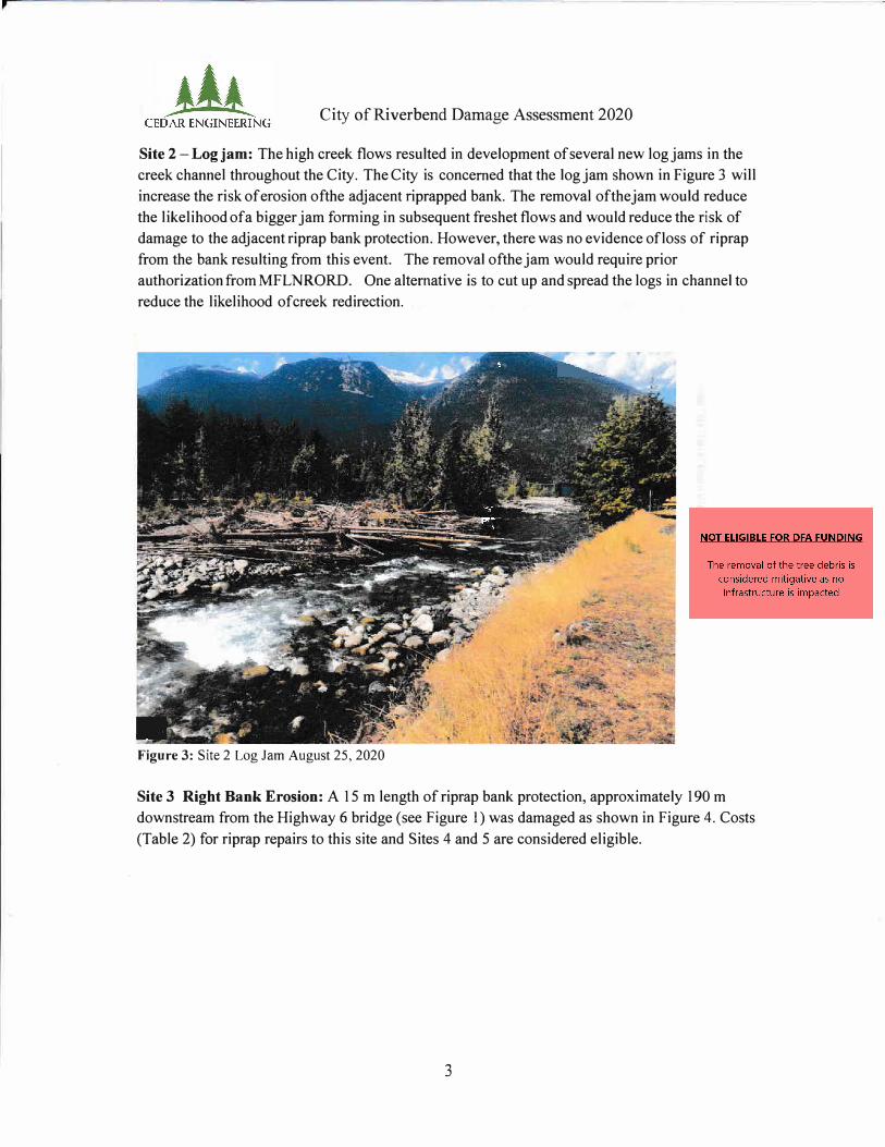
Site 2 - Log jam: The high creek flows resulted in development of several new log jams in the
creek channel throughout the City. The City is concerned that the log jam shown in Figure 3 will
increase the risk of erosion of the adjacent riprapped bank. The removal oft he jam would reduce
the likelihood of a bigger jam forming in subsequent freshet flows and would reduce the risk of
damage to the adjacent riprap bank protection. However, there was no evidence of loss of riprap
from the bank resulting from this event. The removal oft he jam would require prior
authorization from MFLNRORD. One alternative is to cut up and spread the logs in channel to
reduce the likelihood of creek redirection.
Figure 3: Site 2 Log Jam August 25, 2020
Site 3 Right Bank Erosion: A 15 m length of riprap bank protection, approximately 190 m
downstream from the Highway 6 bridge (see Figure I) was damaged as shown in Figure 4. Costs
(Table 2) for riprap repairs to this site and Sites 4 and 5 are considered eligible.
3

,
.
City of Riverbend Damage Assessment 2020
+
Figure 4: Site 3 Riprap Toe Erosion August 25, 2020
I Erod<,d R;prap I
I Waterle·,.,1-August 2�, 2010
�-, I\t --.... � ___ __,._·------
Typical Cross Section
Note to �cale:
Site 4 -Riprap Replacement: Approximately 67 m of bank protection was damaged as shown in Figure 5.
I rip rap lost I
.3.3m
-·-
Typkal Cross Section
Figure 5: Site 4 Riprap Lost August 25, 2020
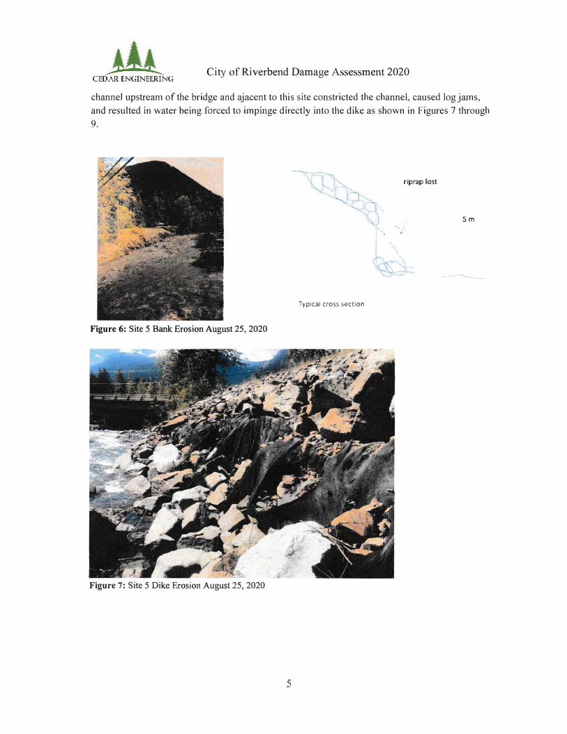
Site 5 Rip rap Replacement: Riprap erosion protection on a 26 m section of dike upstream of the Highway 6 bridge was eroded as shown in Figures 6 to 8. A large gravel bar and trees in the
4
City of Riverbend Damage Assessment 2020
channel upstream of the bridge and ajacent to this site constricted the channel, caused log jams,
and resulted in water being forced to impinge directly into the dike as shown in Figures 7 through
9.
riprap lost
-. I
Sm
•
---
Typical cross section
Figure 6: Site 5 Bank Erosion August 25, 2020
Figure 7: Site 5 Dike Erosion August 25, 2020
5
,
City of Riverbend Damage Assessment 2020
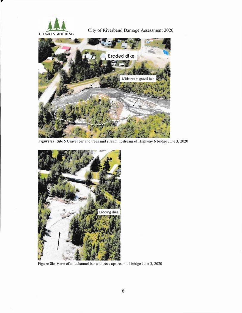
Figure 8a: Site 5 Gravel bar and trees mid stream upstream of Highway 6 bridge June 3, 2020
Figure 8b: View ofmidchannel bar and trees upstream of bridge June 3, 2020
6

City of Riverbend Damage Assessment 2020
Figure 9: View of gravel bar and log jam forcing flood waters to impinge on dike May 31, 2020 ( courtesy
City of Riverbend)
The dike was intially constructed in the l 970's and upgraded in the 1990's. During the 2013
freshet the dike was damaged at this same location with loss of erosion protection and some of
the dike prism as shown in Figure 10. The photo in Figure 10 was taken from CGT Engineeing
letter report to the City dated September 11, 2013. In 2014 the dike slope was reconstructed and
armoured with riprap, as shown in Figure l I, taken from CGT letter report to the City dated
September 8, 2014. It is understood the repairs where funded partially by the Province.
Figure 10: View of Erosion Resulting from June 2013 Flood (CGT 2013)
7

City of Riverbend Damage Assessment 2020
•
Figure 11: September 20 I 4 photo of repaired dike (CGT 20 I 4)
The estimated volume of riprap lost during the May 31 /June 1 event is 143 m3 Simply
reconstructing to the pre-event configuration is not recommended as there would be a high
likelihood of a repeat failure. Conceptual review indicates that the maximum riprap slope angle
should be 1.5H: lV (which is consistent with the 2013 riprap design) and should include a toe
trench (also part of the 2013 design). The riprap placed on the lower slope in 2013 had a lower
slope angle of 1 H: 1 V compensated by larger riprap sizing. In addition, it is recommended that the
gravel bar, logjam and trees shown in Figures 7 and 8 be removed from the channel to realign
flow under the highway bridge and reduce pressure on the dike. Once the channel is cleared the
accumulation of gravel and logjams should be monitored and actions taken to prevent the re
establishment of the channel constriction. This can be facilitated with coordination between the
City, MFLNRORD (Dike Inspection and habitat concerns), DFO and MOTI by updating of the
Vegetion Management Plan. During the May 31/June 1 event the highway bridge sustained
damage in the form of lost riprap that provides pile cap protection (piles now exposed).
The cost of repairs summary (Table 1) for Site 5 is based on the plan to reconstruct the bank with
a flatter slope angle and scour protection described above. The construction will involve instream
work. Consequently, authorization will be required from MFLNRORD. Most likely
MFLNRORD will require an environmental assessment and oversight during construction. This
cost is included in Table 1.
As noted above, Cedar Engineering recommends the removal and subsequent monitoring of the
gravel bar build-up to reduce the risk of future damage to the dike and the highway bridge. This
would include obtaining authourization from MFLNRORD and DFO to complete the intial
gravel and
8
,
City of Riverbend Damage Assessment 2020
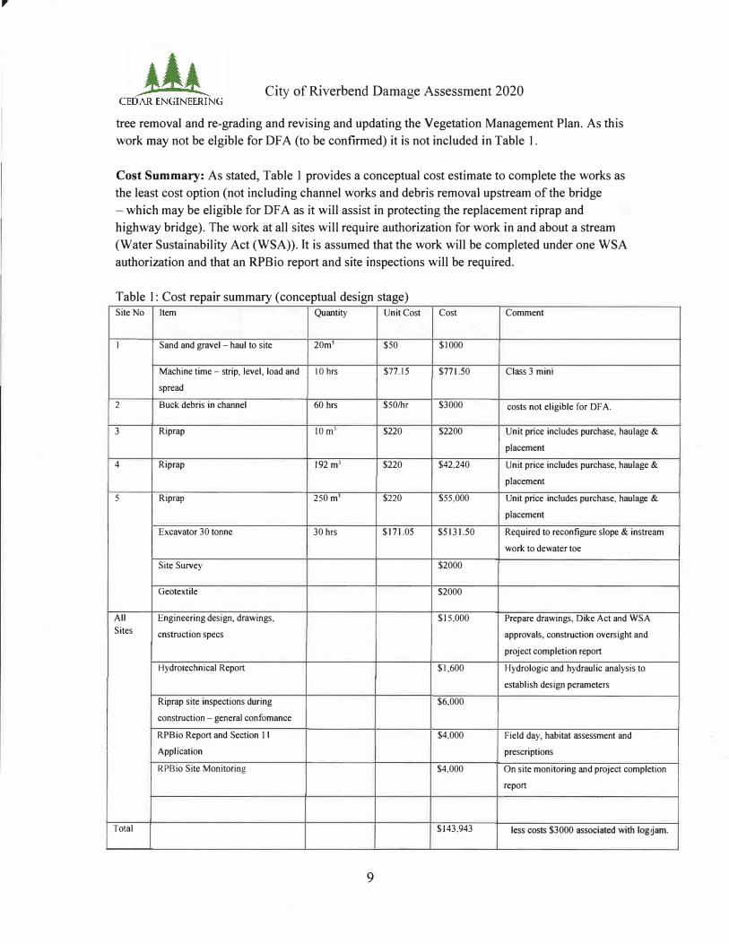
tree removal and re-grading and revising and updating the Vegetation Management Plan. As this
work may not be elgible for DF A (to be confirmed) it is not included in Table 1.
Cost Summary: As stated, Table I provides a conceptual cost estimate to complete the works as
the least cost option (not including channel works and debris removal upstream of the bridge
-which may be eligible for DF A as it will assist in protecting the replacement riprap and
highway bridge). The work at all sites will require authorization for work in and about a stream
(Water Sustainability Act (WSA)). It is assumed that the work will be completed under one WSA
authorization and that an RP Bio report and site inspections will be required.
Table 1: Cost repair summary ( conceptual design stage) Site No Item Quantity Unit Cost Cost Comment
1 Sand and gravel - haul to site 20m3 $50 $1000
Machine time - strip, level, load and IO hrs $77.15 $771.50 Class 3 mini
spread
2 Buck debris in channel 60 hrs $50/hr $3000
3 Riprap !Om' $220 $2200 Unit price includes purchase, haulage &
placement
4 Riprap 192 m3 $220 $42,240 Unit price includes purchase, haulage &
placement
5 Riprap 250 m3 $220 $55,000 Unit price includes purchase, haulage &
placement
Excavator 30 tonne 30 hrs $171.05 $5131.50 Required to reconfigure slope & instream
work to dewater toe
Site Survey $2000
Geotextile $2000
All Engineering design, drawings, $15,000 Prepare drawings, Dike Act and WSA
Sites cnstruction specs approvals, construction oversight and
project completion report
Hydrotechnical Report $1,600 Hydrologic and hydraulic analysis to
establish design perameters
Riprap site inspections during $6,000
construction - general confomance
RPBio Report and Section 11 $4,000 Field day, habitat assessment and
Application prescriptions
RPBio Site Monitoring $4,000 On site monitoring and project completion
report
Total $143,943
9
costs not eligible for DFA.
less costs $3000 associated with log jam.

Any questions please call.
Sincerely,
Chris Arbutus, Cedar Engineering.
City of Riverbend Damage Assessment 2020
10


![Disaster Recovery Center (Disaster Assistance … Library/Disaster Recovery Center...Disaster Recovery Center (Disaster Assistance Center) Standard Operating Guide [Appendix to: ]](https://img.pdfslide.net/doc/110x75/5b0334ba7f8b9a2d518bd9d9/disaster-recovery-center-disaster-assistance-librarydisaster-recovery-centerdisaster.jpg)