Embed Size (px)
Citation preview
b
~~~~1~~ ROLINA DEPARTMENT OF ~ N V I R O N ~ ~ N T , HEALTH, AND NATURAL RESOURCES
James G. Martin Governor
William W. Cobey, Jr. Secretary, EHNR

Recovery of Volatile Organic Compounds from Small
Industrial Sources
Prepared by James J. Spivey
Research Triangle Institute
Prepared for North Carolina Pollution Prevention Pays Program
Department of Natural Resources and Community Development
DISCLAIMER
This p r o j e c t w a s supported by t h e North Carol ina P o l l u t i o n Prevention Pays Program. This does n o t s i g n i f y t h a t t h e contents n e c e s s a r i l y r e f l e c t t h e views and p o l i c i e s of t h e State of North Carol ina, nor does mention of t r a d e names o r commercial products c o n s t i t u t e endorsement o r recommendation f o r use .
Copyright September 19 8 6
North Carol ina P o l l u t i o n Prevention Pays Program Department of Natural Resources and Community Development
Post Off ice Box 27687 Raleigh, North Carol ina 27611-7687
Prepared by
James J. Spivey Research Tr iangle I n s t i t u t e
Post O f f i c e Box 12194 Research Tr iangle Park, North Carol ina 27709
(300 copies repr in ted 1992 a t a c o s t of 7 0 ~ each)
THE POLLUTION PREVENTION PROGRAM
The Pol lu t ion Prevention Program provides f r e e technica l a s s i s t ance t o North Carolina indus t r i e s and munic ipa l i t i es on ways t o reduce, recyc le and prevent wastes before they become p o l l u t a n t s . T h i s non-regulatory program addresses water and a i r q u a l i t y , t o x i c mater ia l s , and s o l i d and hazardous waste. Designated a s t h e lead agency i n waste reduct ion, t h e Program works i n cooperation with the Sol id Waste Management Division and t h e Governor's Waste Management Board. The se rv ices and a s s i s t ance ava i l ab le f a l l i n t o t h e following ca tegor ies :
Information Clearinghouse. An information da ta base provides access t o l i t e r a t u r e sources , contac ts , and case s tud ie s on waste reduct ion techniques f o r s p e c i f i c i n d u s t r i e s o r waste streams. Information is also avai1abl.e through customized computer l i t e r a t u r e searches. Waste reduct ion r epor t s published by t h e Program a r e a l s o ava i l ab le .
Spec i f i c Information Packages. The s t a f f can prepare f a c i l i t y o r waste-stream-specific waste reduct ion r epor t s f o r i n d u s t r i e s and communities. Information provided by t h e f a c i l i t y i s used t o i d e n t i f y c o s t - e f f e c t i v e waste reduct ion opt ions . A s h o r t repor t d e t a i l i n g these opt ions i s provided along with references, case s t u d i e s , and contac ts .
On-si te Technical Assis tance. The s t a f f can provide comprehensive t echn ica l a s s i s t ance through f a c i l i t y v i s i t s . During an o n - s i t e v i s i t , d e t a i l e d process and waste stream information is co l l ec t ed . The information is analyzed, and a s e r i e s of waste reduct ion opt ions a r e i d e n t i f i e d . A repor t i s prepared d e t a i l i n g these opt ions and includes l i t e r a t u r e , contac ts , case s t u d i e s , and vendor information.
Outreach. The s t a f f can g ive presenta t ions on po l lu t ion prevention t o i n d u s t r i e s , t r a d e assoc ia t ions , p rofess iona l organiza t ions , and c i t i z e n groups. Depending on t h e audience, t hese programs range from an overview of t h e S t a t e ' s Po l lu t ion Prevention Program t o in-depth discussions of technologies f o r s p e c i f i c i n d u s t r i e s .
Challenge Grants. A matching grant program provides f inds f o r t h e cos t of personnel, ma te r i a l s , o r consul tan ts needed t o undertake po l lu t ion prevention p r o j e c t s . P ro jec t s e l i g i b l e f o r gran t funds range from cha rac t e r i z ing waste streams i n order t o i d e n t i f y po l lu t ion reduct ion techniques t o conducting in-p lan t and p i l o t - s c a l e s tud ie s of reduct ion technologies .
For information o r t echn ica l a s s i s t ance contac t :
Po l lu t ion Prevention Program Off ice of Waste Reduction N.C. Department of Environment, Health, and Natural Resources P o s t Off ice Box 27687 Raleigh, North Carolina 27611-7687
Telephone: (919) 571-4100

Sec t ion
Table of Contents
1 Introduction.. . . . . . . . . . . . . . . . . . . . . . . . . . . , , . . . . . . . . . . . . . , .
1.0 Process Description... . , . . . . . . . . . . . . . . . . . . . . . . . . . . . . . . . . . 1.1 Adsorption .......................................... 1.2 Absorption .......................................... 1.3 Condensation...................................,....
2.0 Technical Considerations. . . . . . . . . . . . . . . . . . . . . . . . . . . . . . . . . 9 9 2.1 Adsorption... .......................................
2.1.1 Sorbents. . . . . . . . . . . . . . . . . . . . . . . . . . . . . . . . . . . . . 9 2.1.2 Typical Design and Performance Parameters... . 14
2.2 Absorption 19 2.2.1 Absorbent.. . . . . . . . . . . . . . . . . . . . . . . . . . . . . . . . . . . 20
20 2.2.2 Process Configuration ........................ 2.3 Condensation........................................ 22
..........................................
3.0 Economic Considerations... . . . . . . . . . . . . . . . . . . . . . . . . . . . . . . . 25 25
3.2 Absorption 25 3.3 Condensation........................................ 26
3.1 Adsorption.. ........................................ .......................................... 4.0 V e n d o r s . . . . . . . . . . . . . . . . . . . . . . . . . . . . . . . . . . . . . . . . . . . . . . . . . . 30
30 30
4.1 Adsorption. ......................................... 4.2 Absorption .......................................... 4.3 Condensation........................................ 32
5.0 Example C a s e s . . . . . . . . . . . . . . . . . . . . . . . . . . . . . . . . . . . . . . . . . . . . 33 5.1 Adsorption .......................................... 33 5.2 Absorption .......................................... 38 5.3 Condensation........................................ 40
6 . 0 References............................................... 43
Appendix A - Vendor Worksheets f o r Carbon ............... Adsorption Sys te . . . . . . . . . . . . . . . . . . . . . . . . . . . . . . . . . . . . . . . . . 44
List of Figures
g,ae L
1
3
4
L
1
2
3
4
General process flow diagram of an adsorption process for VOC recovery................................. 3
General process flow diagram of a condensation process for VOC recovery....................,............ 6
General process flow diagram of an adsorption process for VOC recovery................................. 8
General ranges of VOC concentration and gas PO flow rate for selected recovery techniques ...............
Adsorption isotherms for two VOCs E2 ....................... Heat Exchanger Costs.,.................................... 27
Cost of Industrial Refrigeration ......................... 27
List of Tables
Practical Guidelines for the Use of Activated Carbon for VOC Recovery .................................. 15
17 Complicating Factors in Carbon Adsorption Design ......... Advantages and Disadvantages of Various Stripping Agents ......................................... 23
Summary of Costs for Condensation and Fixed-Bed Carbon Adsorption 29 ........................................
5 List of Vendors of Activated Carbon Systems for VOC Recovery 31 .........................................
6 34 Information the Buyer Must Supply. .......................
INTRODUCTION
This monograph describes the three generic technologies--adsorption,
absorption, and condensation--available for the recovery of volatile
organic compounds (VOCs) from gas streams generated by small industrial sources. Adsorption is the contact of the VOC-containing gas stream with a solid sorbent followed by regeneration of the spent sorbent, usually in a
cyclic process. nonvolatile liquid in which the VOC is soluble followed by regeneration of the liquid, usually continuously. Condensation is simply the continuous cooling of the gas stream to condense the VOC directly.
Absorption is the contact of the gas stream with a
Because it is the most economical way to remove VOCs from a wide range
of streams encountered in the field, adsorption is by far the most widespread technology for VOC recovery. By choosing an appropriate sorbent
and process configuration, many chemical types of VOCs can be recovered.
Absorption is used where the VOC concentration is relatively high and when
an appropriate inexpensive absorbent liquid is available. Condensation can
be energy intensive and is generally used for gas streams with high VOC content.
Treating a VOC-containing gas stream to recover the VOC(s) is only one
of several broad alternatives to consider. Other alternatives that may be
more economical include process modifications to reduce or eliminate the
VOC content of the gas stream and using an ultimate destruction technique.
A technical and economic evaluation of available alternatives (recovery,
process modification, or ultimate destruction) is a prerequisite to making the right choice f o r VOC control. It is the purpose of this monograph to discuss only recovery and to provide general guidelines for evaluation of
the available recovery techniques for specific cases. This monograph does
not consider VOC control techniques that are primarily means of ultimate
destruction of the VOC, e.g., incineration or catalytic oxidation.
1
1.0 PROCESS DESCRIPTION
1.1 Adsorption
Adsorption is t h e process of adhesion of a very t h i n l a y e r of molecuks
from a gas o r l i q u i d t o t h e su r face of a s o l i d as a r e s u l t of phys ica l og
chemical fo rces between t h e s o l i d and t h e adhering molecules. For t h e
recovery of VOCs , we a r e i n t e r e s t e d exc lus ive ly i n gas-phase molecules
adsorbing on a s o l i d material as a r e s u l t of phys ica l fo rces a lone, wfiic%
permits t h e adsorbed molecule t o be recovered chemically unchanged.
Adsorption processes are extremely f l e x i b l e f o r VOC recovery. By
choosing an appropr ia te adsorbent ( t h e s o l i d i n t h e above d e f i n i t i o n ) and
processing condi t ions , a wide range of VOCs can be recovered cos t
e f f e c t i v e l y . For t h i s reason, numerous commercially a v a i l a b l e processes
have been developed f o r t h i s purpose. For r e l a t i v e l y small i n d u s t r i a l VO9:
sources , systems are a v a i l a b l e t h a t r equ i r e a minimum of maintenance and
opera tor a t t e n t i o n . These systems are usua l ly p r a c t i c a l f o r small f l o w
r a t e s of VOC-containing gas (from s e v e r a l hundred t o t e n s o f thousands 03
f t3 /min) and low VOC concentrat ions (usua l ly s e v e r a l hundred up t o s e v e r d
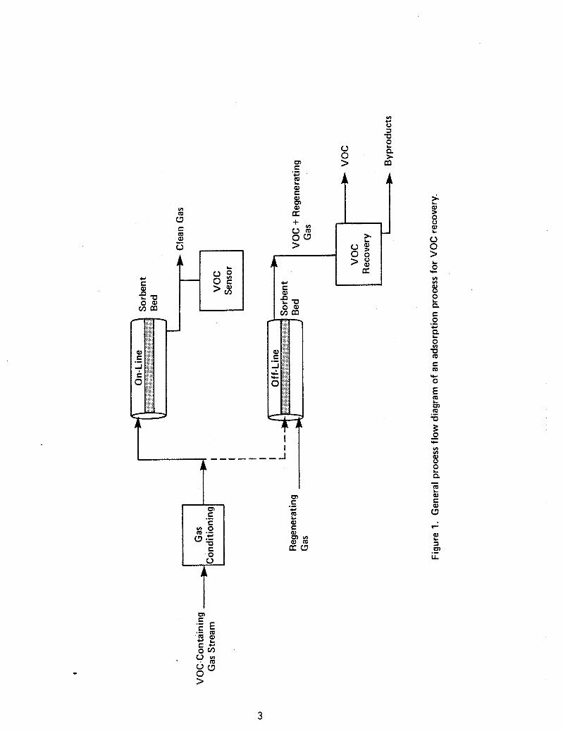
thousand ppm) . Figure 1 i s a genera l schematic diagram of how adsorp t ion is used for;
VOC recovery.
stream and t h e adsorbent may d i f f e r among vendors of var ious systems, i n
p r i n c i p l e a l l c y c l i c adsorp t ion systems f o r VOC recovery can be represented
by t h e process shown.*
by a p a r t i c u l a t e f i l t e r and perhaps a cooler /dehumidif ier .
contacted with a bed of t h e sorbent material, u sua l ly a f ixed bed of
granular a c t i v a t e d carbon. The VOC is p r e f e r e n t i a l l y adsorbed from t h e p s
Although t h e s p e c i f i c d e t a i l s of contac t ing between t h e gas
The VOC-containing gas stream i s f i r s t condi t io&
It is then
*While a l l subsequent d i scuss ion of VOC recovery by adsorp t ion is based m t h e type of system shown i n Figure 1, two o the r types of adsorp t ion VOC recovery systems are ava i lab le . One involves adsorp t ion under pressure wi th regenera t ion accomplished by pressure reduction. Such "pressure swing" systems a r e not genera l ly used f o r VOC recovery, but i n p r i n c i p l e could be ( see re ference 1). The second involves continuous contac t of t h e gas and sorbent s t ream i n a f l u i d i z e d bed conf igura t ion . Such systans a r e not pract ical f o r t h e r e l a t i v e l y low f low r a t e s considered he re in , bt should be evaluated f o r l a r g e r flows ( s e e re ference 4, p. 701) .
2
I.' E W e , $ 8
3
st ream and t h e c l ean gas leaves t h e sorbent bed.
exhausted, i . e . , when t h e VOC concent ra t ion i n t h e o u t l e t gas s t ream
exceeds a maximum acceptab le l e v e l ( t h i s is c a l l e d "breakthrough"), t h e bed
is taken o f f - l i n e f o r regenerat ion and t h e VOC-containing gas stream i s
d ive r t ed t o a f r e s h (regenerated) sorbent bed. For continuous VOC removal,
t h i s implies t h e need f o r a t l e a s t two, and perhaps more, sorbent beds
opera t ing i n p a r a l l e l . Regeneration of t h e spent sorbent can be done on-
s i t e (as shown) o r o f f - s i t e by t h e sorbent vendor o r by a for - fee
regenera t ion service.
pressure (N15 p s i g ) steam. Other regenerat ing gases a r e sometimes used i n
s p e c i a l cases ( see Sec t ion 2.1) . I f steam i s used, hea t re leased by
When t h e bed is
The most c o m n method of regenerat ion is by low-
condensation of t h e steam causes t h e VOC t o desorb from t h e sorbent and the
r e s u l t i n g vapor mixture is condensed downstream of t h e sorbent bed. The
condensed l i q u i d is allowed t o sepa ra t e i n t o two phases. The recovered VQC
is then decanted and is ava i l ab le f o r re-use o r s a l e . ( I n t h i s case , t h e
block i n Figure 1 labe led "VOC recovery" would c o n s i s t of a condenser and
decanter . )
t rea tment , sub jec t t o r e s t r i c t i o n s discussed i n Sec t ion 2.1.
The aqueous phase can then be s e n t d i r e c t l y t o wastewater
1.2 Ah2qDtion
Absorption is t h e t r a n s f e r of one component of a gas mixture t o a
l i q u i d due t o p r e f e r e n t i a l s o l u b i l i t y of t h e gas i n t h e l iqu id .* For VOC
recovery, t h i s process involves t h e t r a n s f e r of t h e VOC from a gas stream
t o a s u i t a b l e l i q u i d i n which t h e VOC i s so luble .
I n p r i n c i p l e , almost a l l VOCs can be recovered from any gas mixture by
s e l e c t i o n of an appropr ia te l i q u i d absorbent and opera t ing condi t ions.
Although absorp t ion is probably t h e most important gas-phase p o l l u t i o n
c o n t r o l operat ion7 ( f o r removal of ac id s t a c k gases , f o r example), i t s use
f o r VOC recovery from small i n d u s t r i a l sources is not widely prac t iced .8
Its r e l a t i v e l y complex opera t ion and t h e consequent c o s t account f o r i ts
l imi t ed use.
*Absorption is sometimes accompanied by chemical r eac t ion o r complexation of t h e absorbate ( t h e so lub le gas i n t h i s d e f i n i t i o n ) with, or i n , t h e absorbent. This process is not appl icable t o VOC recovery, however.
4
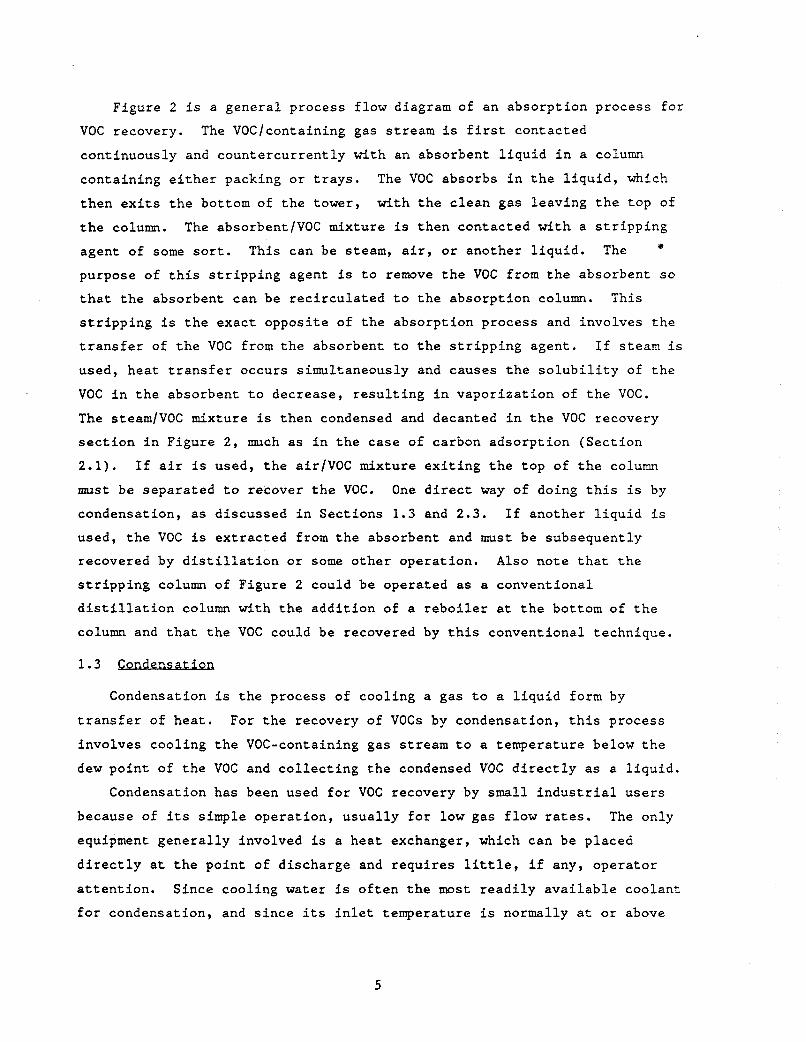
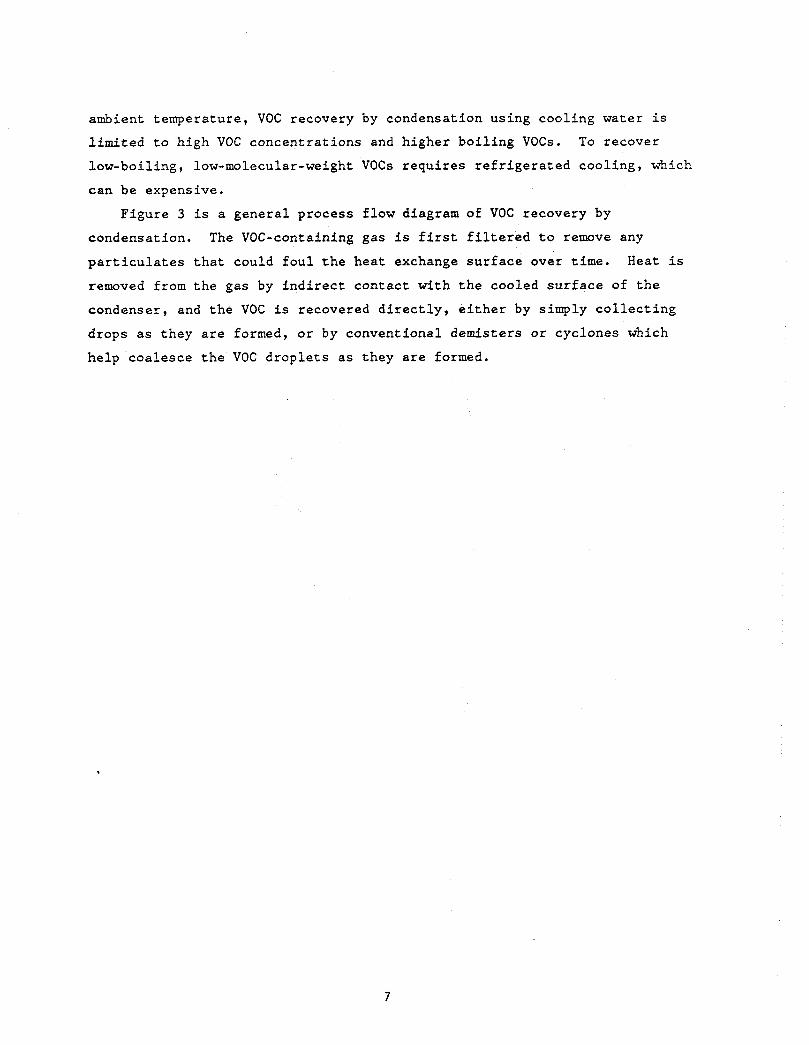
Figure 2 is a general process f low diagram of an absorp t ion process f o r
VOC recovery.
continuously and countercur ren t ly with an absorbent l i q u i d i n a column
containing e i t h e r packing o r t r a y s .
then e x i t s t h e bottom of t h e tower, with t h e c l ean gas leaving t h e top of
t h e column.
agent of some s o r t . This can be steam, a i r , o r another l i q u i d . The
purpose of t h i s s t r i p p i n g agent is t o remove t h e VOC from t h e absorbent so
t h a t t h e absorbent can be r ec i r cu la t ed t o t h e absorp t ion column. This
s t r i p p i n g is t h e exact opposi te of t h e absorpt ion process and involves t h e
t r a n s f e r of t h e VOC from t h e absorbent t o t h e s t r i p p i n g agent . I f steam i s
used, hea t t r a n s f e r occurs simultaneously and causes t h e s o l u b i l i t y of t h e
VOC i n t h e absorbent t o decrease, r e s u l t i n g i n vapor iza t ion of t h e VOC.
The steam/VOC mixture is then condensed and decanted i n t h e VOC recovery
s e c t i o n i n Figure 2 , much as i n t h e case of carbon adsorp t ion (Sect ion
2 .1) .
must be separa ted t o recover t h e VOC. One d i r e c t way of doing t h i s is by
condensation, as discussed i n Sect ions 1.3 and 2.3. I f another l i q u i d i s
used, t h e VOC is ex t rac ted from t h e absorbent and m u s t be subsequently
recovered by d i s t i l l a t i o n o r some o the r operat ion. A l s o note t h a t t h e
s t r i p p i n g column of Figure 2 could be operated as a convent ional
d i s t i l l a t i o n column with t h e add i t ion of a r e b o i l e r a t t h e bottom of t h e
column and t h a t t h e VOC could be recovered by t h i s conventional technique.
The VOClcontaining gas s t ream is f i r s t contacted
The VOC absorbs i n t h e l i q u i d , which
The absorbent/VOC mixture is then contacted wi th a s t r i p p i n g
I f a i r i s used, t h e a i r / V O C mixture e x i t i n g t h e top of t h e column
1.3 Condensation
Condensation is the process of cool ing a gas t o a l i q u i d form by
t r a n s f e r of hea t . For t h e recovery of VOCs by condensation, t h i s process
involves cool ing t h e VOC-containing gas stream t o a temperature below t h e
dew po in t of t h e VOC and c o l l e c t i n g t h e condensed VOC d i r e c t l y as a l i q u i d .
Condensation has been used f o r VOC recovery by small i n d u s t r i a l u se r s
because of i ts simple opera t ion , u sua l ly fo r low gas f low r a t e s . The only
equipment genera l ly involved is a hea t exchanger, Which can be placed
d i r e c t l y a t t h e poin t of discharge and requi res l i t t l e , i f any, opera tor
a t t e n t i o n . Since cool ing water is o f t e n t h e most r e a d i l y a v a i l a b l e coolant
f o r condensation, and s ince i t s i n l e t temperature is normally a t o r above
5
6
ambient temperature, VOC recovery by condensation using cool ing water i s
l imi t ed t o high VOC concentrat ions and higher bo i l ing VOCs.
low-boiling, low-molecular-weight VOCs requi res r e f r i g e r a t e d cool ing, which
can be expensive.
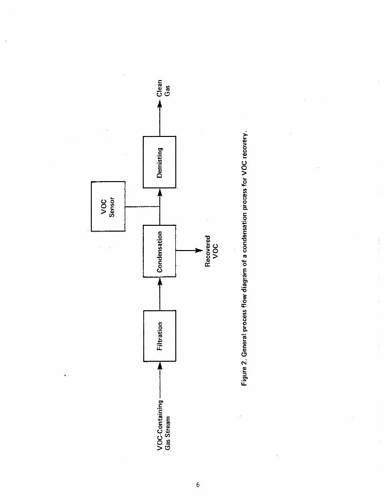
Figure 3 is a genera l process f low diagram of VOC recovery by
To recover
condensation. The VOC-containing gas is f i r s t f i l t e r e d t o remove any
p a r t i c u l a t e s t h a t could fou l t h e hea t exchange su r face over t i m e .
removed from the gas by i n d i r e c t contac t with t h e cooled su r face of t h e
condenser, and t h e VOC is recovered d i r e c t l y , e i t h e r by simply c o l l e c t i n g
drops as they a r e formed, o r by conventional demisters or cyclones which
he lp coalesce t h e VOC drop le t s as they a r e formed.
Heat i s
7
Clean Gas
Absorbent * Liquid
4dsorp ti oi Column
V OC-Con tain ing I
Gas Stream
Stripping Column
By products
Regenerated 9 Stripping Agent Absorbent Liquid
Figure 3. General process flow diagram of an absorption process for VOC recovery.
2.0 TECHNICAL. CONSIDERATIONS
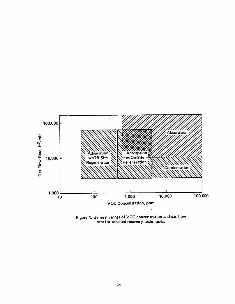
Figure 4 shows approximate ranges of VOC concentrat ions and flow r a t e s
t o which t h e t h r e e technologies considered i n t h i s monograph can be
appl ied. L i m i t s of app l i ca t ion of t hese technologies a r e both t echn ica l
and economic, and a r e discussed i n Sect ions 2.0 and 3.0.
2.1 AdsorDtion
To eva lua te s p e c i f i c adsorpt ion processes f o r a given VOC recovery
need, t h e sorbent i t s e l f and the o v e r a l l process design parameters must be
cons ide red . 2.1.1 Sorbents
I n p r i n c i p l e , many sorbents could be used f o r VOC recovery. These
include ac t iva t ed carbon, molecular s i eves , ac t iva t ed alumina, and
ac t iva t ed s i l i c a . The only sorbent used i n commercial VOC recovery s y s t e m
is a c t i v a t e d carbon. The preference f o r ac t iva t ed carbon der ives from i t s
r e l a t i v e i n s e n s i t i v i t y t o w a t e r vapor, high su r face a rea , high s o r p t i v e
capac i ty f o r a wide range of VOCs, and low cos t . Although o the r sorbents
with s u i t a b l e chemical and phys ica l p rope r t i e s may e x i s t , they have not ye t
been used i n commercially ava i l ab le systems f o r VOC recovery.
The equi l ibr ium between a VOC and a sorbent such as ac t iva t ed carbon
can be adequately represented by an equat ion t h a t expresses t h e weight of
an adsorbate ( i . e . , a VOC) t h a t can be adsorbed pe r u n i t mass of sorbent at
egAUg&m ( W i , i n u n i t s of l b of adso rba te / lb of so rben t ) a s a func t ion
of t h e p a r t i a l p ressure of t h e VOC i n t h e gas s t ream ( P i , i n u n i t s of mm
Hg) i n a form known as t h e Freundlich isotherm:
where n is g rea t e r than 1. Both n and a are empir ica l ly determined
cons t an t s , both of which genera l ly decrease with increas ing temperature.
This suggests t h a t a given sorbent w i l l absord less of a given adsorbate
( a t equi l ibr ium) a t a higher temperature. This p r i n c i p l e is used t o
regenerate a spent sorbent by hea t ing it, wi th steam f o r example. The
va lues of n and a a r e a l s o unique t o a given sorbent-adsorbate system.
Because a unique r e l a t ionsh ip e x i s t s between a given adsorbate (e .g . , a
9
100,000 - C .- E
"w \
.c
d = 10,000 - 6 m
h % (3
i I I I 1,000 10,000 100,om 1,000
10 100
VOC Concentration, ppm
Figure 4. General ranges of VOC concentration and gas flow rate for selected recovery techniques.
VOC) and a sorbent ( e , g . , a c t iva t ed carbon) a t a given temperature,
equat ion (1) is c a l l e d an isotherm.
necessary t e s t s on a given VOC gas stream t o determine t h e genera l shape of
t h e isotherm i f they do not a l ready have experience with t h e p a r t i c u l a r gas
composition. Kovach5 gives a procedure f o r c a l c u l a t i n g t h e isotherm a t any
temperature knowing i ts shape a t one temperature is known.
Often, vendors w i l l perform t h e
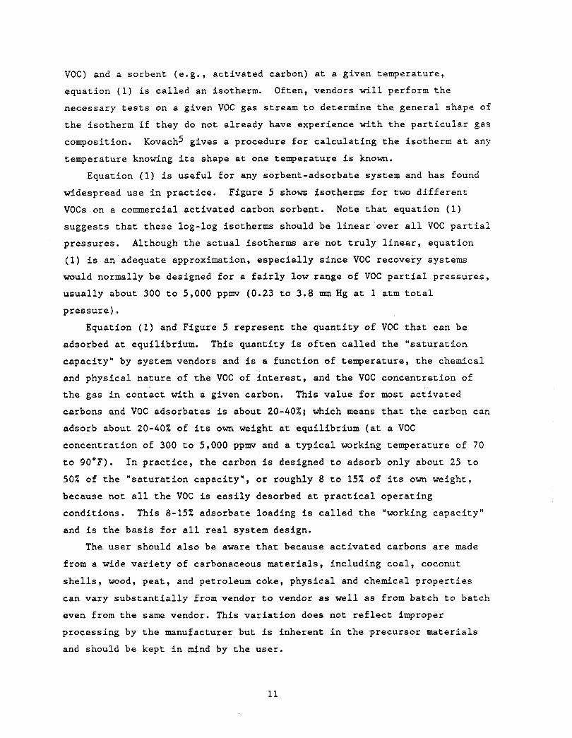
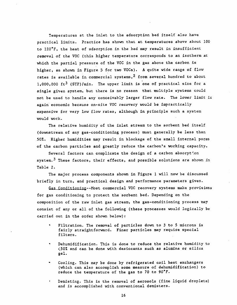
Equation (1) i s use fu l f o r any sorbent-adsorbate system and has found
widespread use i n p rac t i ce .
VOCs on a commercial ac t iva t ed carbon sorbent .
suggests t h a t t hese log-log isotherms should be l i n e a r over a l l VOC p a r t i a l
pressures . Although t h e a c t u a l isotherms are not t r u l y l i n e a r , equat ion
(1) i s an adequate approximation, e s p e c i a l l y s i n c e VOC recovery systems
would normally be designed f o r a f a i r l y low range of VOC p a r t i a l p re s su res ,
u sua l ly about 300 t o 5,000 ppmv ( 0 . 2 3 t o 3 . 8 mm Hg a t 1 a t m t o t a l
p r e s s u r e ) .
Figure 5 shows isotherms for two d i f f e r e n t
Note t h a t equat ion (1)
Equation (1) and Figure 5 represent t h e quan t i ty of VOC t h a t can be
adsorbed a t equi l ibr ium. This quan t i ty is o f t e n c a l l e d t h e " s a t u r a t i o n
capac i ty" by system vendors and i s a func t ion of temperature, t h e chemical
and phys ica l na ture of t h e VOC of i n t e r e s t , and t h e VOC concent ra t ion of
t h e gas i n contac t with a given carbon. This va lue for most ac t iva t ed
carbons and VOC adsorbates is about 20-40%; which means t h a t t h e carbon can
adsorb about 20-40% of i t s own weight a t equi l ibr ium ( a t a VOC
concent ra t ion of 300 t o 5,000 p p w and a t y p i c a l working temperature of 70
t o 90°F).
50% of t h e " sa tu ra t ion capac i ty" , or roughly 8 t o 15% of i t s own weight,
because not a l l t h e VOC is e a s i l y desorbed a t p r a c t i c a l opera t ing
condi t ions . This 8-25% adsorbate loading is called t h e "working capac i ty"
and i s t h e b a s i s f o r a l l r e a l system design.
I n p r a c t i c e , t h e carbon is designed t o adsorb only about 25 t o
The use r should a l s o be aware t h a t because ac t iva t ed carbons a r e made
from a wide v a r i e t y of carbonaceous ma te r i a l s , including coa l , coconut
s h e l l s , wood, pea t , and petroleum coke, phys ica l and chemical p r o p e r t i e s
can vary s u b s t a n t i a l l y from vendor t o vendor as w e l l as from batch t o batch
even from t h e
processing by
and should be
s a m e vendor. This v a r i a t i o n does not r e f l e c t improper
t h e manufacturer but is inherent i n t h e precursor ma te r i a l s
kept i n mind by t h e user .
11
100 80 m
20
10 8 6
- 4
2
I 01 10 IO I00 1000
Pressure, mm Hg Methyl ethyl ketone adsorptioll i\otherms on Union Carbide 45 cerl~on. (a)
100 80 60 40 8
c 3 5 20
8 IO
- g 6
f!
0 8
s 4 a
2
I 01 10 IO 100 1000
Pressure, mm Hg Acetone .idwq,tion isotl~emi* o i i Unioii C.uliide 15 cnrlicrn (b)
Figure 5. Adsorption isotherms for two VOCs (from Kovach,J.L.,in Handbook of Separation Techniques f o r Chemical Engineers, P.A. Schweitzer ed., McGraw Hill, 1979, p . 3-14).
12
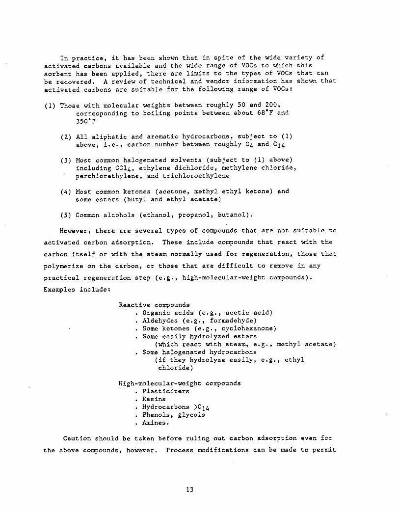
I n p r a c t i c e , it has been shown t h a t i n s p i t e of t h e wide v a r i e t y of ac t iva t ed carbons ava i l ab le and t h e wide range of VOCs t o which t h i s sorbent has been appl ied , t h e r e a r e limits t o t h e types of VOCs t h a t can be recovered. A review of t echn ica l and vendor information has shown t h a t a c t i v a t e d carbons a r e s u i t a b l e f o r t h e following range of VOCs:
(1) Those with molecular weights between roughly 50 and 200, corresponding t o bo i l ing po in t s between about 68'F and 350'F
( 2 ) All a l i p h a t i c and aromatic hydrocarbons, sub jec t t o (1) above, i .e. , carbon number between roughly C4 and C14
( 3 ) Most common halogenated so lvents ( sub jec t t o (1) above) including C C l 4 , e thylene d i ch lo r ide , methylene ch lo r ide , perchlorethylene, and t r i ch lo roe thy lene
( 4 ) Most common ketones (acetone, methyl e t h y l ketone) and some e s t e r s (bu ty l and e t h y l a c e t a t e )
( 5 ) Common a lcohols (e thanol , propanol, bu tanol ) .
However, t h e r e a r e seve ra l types of compounds t h a t are not s u i t a b l e t o
a c t i v a t e d carbon adsorpt ion. These include compounds t h a t r e a c t with t h e
carbon i t s e l f o r with the steam normally used f o r regenera t ion , those t h a t
polymerize on t h e carbon, o r those t h a t a r e d i f f i c u l t t o remove i n any
p r a c t i c a l regenerat ion s t e p (e .g . , high-molecular-weight compounds).
Examples include:
Reactive compounds . Organic ac ids (e.g. , a c e t i c a c i d ) . Aldehydes (e.g., formadehyde) . Some ketones (e .g . , cyclohexanone) . Some e a s i l y hydrolyzed e s t e r s
. Some halogenated hydrocarbons (which r eac t with steam, e.g., methyl a c e t a t e )
( i f they hydrolyze e a s i l y , e.g., e t h y l ch lo r ide )
High-molecular-weight compounds . P l a s t i c i z e r s . Resins . Hydrocarbons >C14 . Phenols, g lycols . Amines.
Caution should be taken before r u l i n g out carbon adsorp t ion even f o r
t h e above compounds, however. Process modif icat ions can be made t o permit
13
economical recovery of t hese VOCs by carbon adsorpt ion. As an example, the
carbon can be regenerated with a hot i n e r t gas such a s n i t rogen ( in s t ead of
steam) t o e l imina te t h e hydrolysis r eac t ion of some e s t e r s and halogens
wi th steam. Vendors (Sect ion 4.1) should be consul ted f o r guidance on
ind iv idua l problems.
2.1.2 Typical System Design and Performance Parameters
Years of p r a c t i c e i n t h e use of ac t iva t ed carbon adsorp t ion f o r VOC
recovery have l ed t o genera l gu ide l ines f o r system design and performance.
The purpose of t h i s s e c t i o n is t o summarize these gu ide l ines , f i r s t i n
terms of o v e r a l l performance and second i n terms of each major process step
shown i n Figure 1.
Qyerall Perfo=--Table 1 summarizes t h e major c h a r a c t e r i s t i c s of a
VOC-containing gas s t ream t o which ac t iva t ed carbon adsorp t ion can be
p r a c t i c a l l y appl ied.
As a r u l e , a well-designed carbon adsorp t ion system f o r VOC recovery
is s u i t a b l e f o r handling gases with VOC concent ra t ions of s e v e r a l hundred
to about 5,000 ppm. The upper l i m i t on VOC content i s due to heat t r a n s f e r
l i m i t s and s a f e t y . Because adsorp t ion is always an exothermic process
(wi th a hea t of adsorp t ion roughly equal t o t h e hea t of condensation,
B tu / lb VOC) , t h e higher t h e VOC content of t h e i n l e t gas s t ream (e.g., lb
VOC/lb incoming g a s ) , t h e higher t h e t o t a l hea t evolved when the VOC is
adsorbed (B tu l lb incoming gas) . As t h e VOC conten t of t h e gas increases ,
hea t is evolved f a s t e r than it can be removed i n a f ixed-sorbent bed and
t h e bed temperature may r i s e t o unsafe l e v e l s . The upper VOC concentrat ian
can a l s o be l imi t ed by the explosive limits of t h e gas (usua l ly a i r ) / V O C
mixture. One EPA repor t s t a t e s t h a t insurance companies l i m i t i n l e t gas
concent ra t ion t o <25% of t h e lower explosive l i m i t (LEL), un less s p e c i a l
c o n t r o l s a r e added ( i n which case up t o 40-50% of the(LEL) can be
t o l e r a t e d ) . 2 The lower l i m i t on VOC content is usua l ly economic.
VOC l e v e l s , it is not cos t - e f f ec t ive t o pay f o r t h e VOC recovery equipment
(see Sec t ion 3.1) because t h e bed w i l l genera l ly not become exhausted f o r
q u i t e some time, i n which case o f f - s i t e regenera t ion of t h e sorbent i s moxe
economical. Activated carbon adsorpt ion wi l l s t i l l remove t h e VOCs even at
i n l e t l e v e l s of s e v e r a l ppm; cos t a lone determines whether VOC recovery at
t h e s e l e v e l s is reasonable. A l e v e l of s e v e r a l hundred ppm has been
reported to be a p r a c t i c a l economic l i m i t . 3 t 4
A t low
14
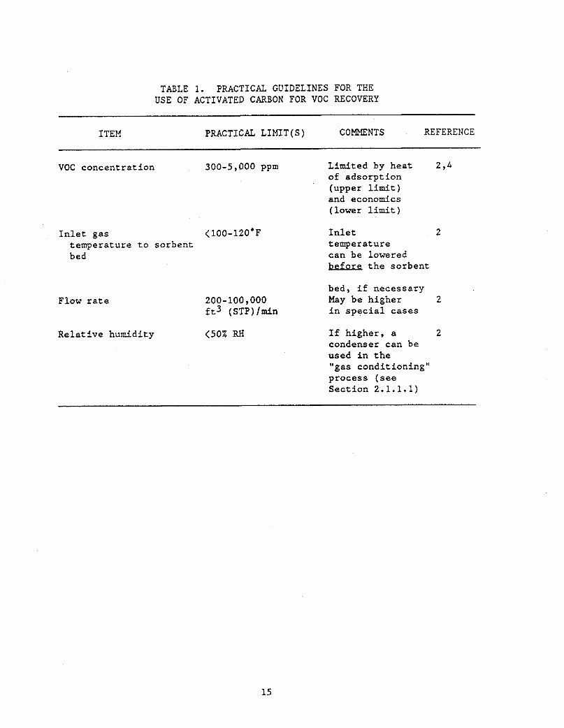
TABLE 1. PRACTICAL GUIDELINES FOR THE USE OF ACTIVATED CARBON FOR VOC RECOVERY
ITEM PRACTICAL LIMIT(S) COMMENTS REFERENCE
VOC concentration 300-5,000 ppm Limited by heat 2 ,4 of adsorption (upper limit) and economics (lower limit)
Inlet gas < 100- 120.F temperature to sorbent bed
Flow rate
Relative humidity
200-100,000 ft3 ( ~ ~ ~ ) / m i n
Inlet temperature can be lowered before the sorbent
2
bed, if necessary
in special cases May be higher 2
<SO% RH If higher, a 2 condenser can be used in the "gas conditioning" process (see Section 2.1.1.1)
15
Temperatures a t t h e i n l e t t o t h e adsorpt ion bed i t s e l f a l s o have
p r a c t i c a l limits.
t o 120'F, t h e hea t of adsorpt ion i n t h e bed may r e s u l t i n i n s u f f i c i e n t
removal of t h e VOC ( t h i s higher temperature corresponds t o an isotherm at.
which t h e p a r t i a l p ressure of t h e VOC i n t h e gas above t h e carbon is
higher , as shown i n Figure 5 f o r two VOCs) .
rates is a v a i l a b l e i n commercial systems,2 from s e v e r a l hundred t o about
1,000,000 f t 3 (STP)/min. The upper l i m i t is *one of p r a c t i c a l s i z e f o r a
s i n g l e given system, but t h e r e is no reason t h a t mul t ip le systems could
not be used t o handle any conceivably l a r g e r f l o w r a t e .
again economic because o n - s i t e VOC recovery would be imprac t i ca l ly
expensive f o r very low f low r a t e s , al though i n p r i n c i p l e such a system
would work.
P r a c t i c e has shown t h a t a t temperatures above about 100
A q u i t e wide range of flow
The l o w e r l i m i t Is
The r e l a t i v e humidity of t h e i n l e t stream t o t h e sorbent bed i t s e l f
(downstream of any gas-conditioning process) must genera l ly be l e s s than
50%.
of t h e carbon p a r t i c l e s and g r e a t l y reduce t h e carbon's working capac i ty-
Higher humidi t ies may r e s u l t i n blockage of t h e small i n t e r n a l pores
Severa l f a c t o r s can complicate t h e design of a carbon absorptx.on
systems3 These f a c t o r s , t h e i r e f f e c t s , and poss ib l e s o l u t i o n s a r e shown i n
Table 2.
The major process components shown i n Figure 1 w i l l now be discussed
b r i e f l y i n t u r n , and p r a c t i c a l design and performance parameters given.
Gas Co---Most commercial VOC recovery systems make provis ions
f o r gas condi t ion ing t o p r o t e c t t h e sorbent bed. Depending on t h e
composition of t h e raw i n l e t gas stream, t h e gas-conditioning process may
c o n s i s t of any or a l l of t h e following ( these processes would l o g i c a l l y be
c a r r i e d out i n t h e order shown below):
F i l t r a t i o n . The removal of p a r t i c l e s down t o 3 t o 5 microns is f a i r l y s t ra ight forward . f i l t e r s . Finer p a r t i c l e s may r equ i r e s p e c i a l
Dehumidification. This is done t o reduce t h e r e l a t i v e humidity to <50% and can be done with des iccants such as alumina o r s i l i c a ge l .
Cooling. This may be done by r e f r i g e r a t e d c o i l hea t exchangers (which can a l s o accomplish some measure of dehumidif icat ion) t o reduce t h e temperature of t h e gas t o 70 t o 90.F.
* Demisting. This is t h e removal of ae roso l s ( f i n e l i q u i d d rop le t s ) and is accomplished with conventional demisters.
16
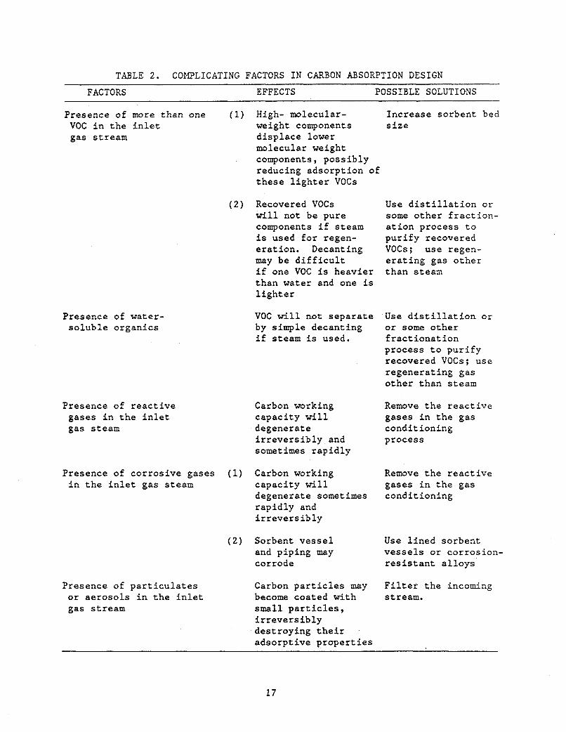
TABLE 2. COMPLICATING FACTORS IN CARBON ABSORPTION DESIGN FACTORS EFFECTS POSSIBLE SOLUTIONS
Presence of more than one (1) High- molecular- Increase sorbent bed VOC i n t h e i n l e t weight components s i z e gas stream d i sp lace lower
mo 1 e cu 1 ar we i gh t components, poss ib ly reducing adsorpt ion of t hese l i g h t e r VOCs
( 2 ) Recovered VOCs Use d i s t i l l a t i o n o r w i l l not be pure some o the r f r a c t i o n - components i f steam a t i o n process t o is used f o r regen- p u r i f y recovered e ra t ion . Decanting VOCs; use regen- may be d i f f i c u l t e r a t i n g gas o the r i f one VOC is heavier than steam than water and one is l i g h t e r
Presence of water- so lub le organics
Presence of r e a c t i v e gases i n t h e i n l e t gas steam
VOC w i l l not s epa ra t e Use d i s t i l l a t i o n o r by simple decant ing o r some o the r i f steam is used. f r a c t i o n a t i o n
process t o p u r i f y recovered VOCs; use regenera t ing gas o the r than s t e a m
Carbon working Remove t h e r e a c t i v e capac i ty wi l l gases i n t h e gas degenerate condi t ioning i r r e v e r s i b l y and process sometimes rap i d l y
Presence of cor ros ive gases (1) Carbon working i n t h e i n l e t gas steam capac i ty w i l l
degenerate sometimes rap id ly and i r r e v e r s i b l y
( 2 ) Sorbent v e s s e l and piping may corrode
Presence of p a r t i c u l a t e s Carbon p a r t i c l e s may or ae roso l s i n t h e i n l e t become coated with gas s t ream small p a r t i c l e s ,
i r r e v e r s i b l y destroying t h e i r adsorp t ive p rope r t i e s
Remove t h e r e a c t i v e gases i n t h e gas condi t ioning
Use l i n e d sorbent v e s s e l s o r corrosion- r e s i s t a n t a l l o y s
F i l t e r t h e incoming stream.
17
Sprbent Bed--The sorbent bed i t s e l f is gene ra l ly capable of
accomplishing an o v e r a l l VOC removal of a t least 95% and usua l ly 99% o r
b e t t e r . 273,4
r o u t i n e l y and 10 t o 20-ppm l e v e l s can be reached f o r many compounds.
adsorp t ion capac i ty of t h e bed, being a d i r e c t func t ion of t h e equi l ibr ium
capac i ty as shown i n Figure 5, is g r e a t e r a t lower temperatures. Thus, the
l o w e r t h e temperature of t h e i n l e t gas , t h e higher t h e working capac i ty o f
Out le t VOC concentrat ions of 50 t o 100 ppm can be achieved
The
t h e bed. Also , as a genera l r u l e , unsaturated compounds (alkenes, alkynes,
aromatics) a r e more s t rong ly adsorbed than sa tu ra t ed compounds of s i m i l a r
carbon number.
unsa tura ted compounds a t given condi t ions.
Thus higher removal e f f i c i e n c i e s w i l l be obtained f o r these
The VOC concent ra t ion i n t h e o u t l e t s t ream w i l l gradual ly increase
wi th time a f t e r an i n i t i a l break-in per iod of s e v e r a l days.
adequate removal e f f i c i e n c y r equ i r e s pe r iod ic replacement of a t l e a s t a
po r t ion of t h e carbon bed. Proper system design should r e s u l t i n a carbon
bed l i f e of up t o 5 years . This is accounted f o r e x p l i c i t l y i n
Sec t ion 3.1, where t h e economics of carbon adsorp t ion VOC recovery a r e
discussed.
Maintaining
The carbon bed depth wi th in t h e sorbent v e s s e l is normally f ixed by
experience.
inches being t y p i c a l , t o achieve adequate mass t r a n s f e r of t h e VOC t o the
pores of t h e ind iv idua l carbon p a r t i c l e s a t t y p i c a l l i n e a r gas v e l o c i t i e s
through t h e bed of 30 t o 100 f t lmin (with 50 f t l m i n being a good average
value3p4).
a normal granular ac t iva t ed carbon, of about 0.5 inch H20 per inch
depth.
Usually, t h e bed depth must be between 1 and 3 f e e t , 4 with 18
This f low rate r e s u l t s i n a pressure drop through t h e bed, for
bed
Beds a r e usua l ly s i z e d f o r an on-l ine "cycle" t i m e of s eve ra l hours.
T'nis is based on t h e t i m e needed t o desorb t h e VOC and dry t h e sorbent bed
( i f s t e a m is used) i n a two-bed system.
Steam usage (@ 15 p s i g ) f o r regenerat ion of most carbonlVOC
combinations v a r i e s between 0.25 and 0.35 l b s teaml lb carbon.
VOC Recovery--After t h e VOC has been adsorbed by carbon, it must be
desorbed by a regenerat ing gas.
s t e a m , though of f - the-she l f systems using hot a i r , n i t rogen , o r o t h e r gases
a r e a v a i l a b l e f o r s p e c i a l cases (discussed above). I .
The most widely used regenerat ing gas is
18
I f steam is used, t h e VOC recovery process of Figure 1 c o n s i s t s of a
If condenser and a decanter f o r g rav i ty sepa ra t ion of t h e VOC and water.
t he VOC i s water- insoluble , t h i s s epa ra t ion is simple and t h e VOC is
recovered f o r reuse while t he water is simply discharged without f u r t h e r
t reatment or is re-used f o r b o i l e r makeup. I f t h e VOC is water so lub le and
steam is used as t h e regenerant gas , then t h e VOC must be separa ted from
t h e water, usua l ly by d i s t i l l a t i o n or ex t r ac t ion . Commercial systems a r e
ava i l ab le t o do t h i s (See Sec t ion 4.1) .
removal of organics i n t h e water t o acceptable l e v e l s f o r discharge. Note
t h a t t h e r e are s t r i c t limits t o t h e organic content of water acceptable t o
many municipal sewage t reatment systems; u sua l ly , "percent" l e v e l s of
organics a r e unacceptable. Very low l e v e l s must be achieved i f t h e organic
is toxic . One vendor has s t a t e d t h a t t h e presence of water-soluble VOCs i n
t h e gas s t ream i s probably t h e s i n g l e b igges t disadvantage t o t h e use of
carbon adsorpt ion f o r VOC recovery.3
Care must be taken t o a l low f o r
I f an i n e r t gas i s used t o regenerate t h e bed, then t h e VOC may be
recovered by condensation of t he VOC from the presumably concentrated
regenerat ing gas stream, or may be inc ine ra t ed t o recover i t s f a e l value
( t h i s is not cos t e f f e c t i v e for halogenated so lven t s because they have low
heat ing va lue , a r e cor ros ive t o i n c i n e r a t o r i n t e r n a l s , and probably r equ i r e
c o s t l y f l u e gas t rea tment ) . Both types of systems a r e commercially
ava i l ab le ( s e e Sect ion 4.1) .
2 .2 Absorpt&a
While absorpt ion is not used f o r VOC recovery from small i n d u s t r i a l
sources (EPA r epor t s "...no known systems o f fe red by equipment
manufacturers" fo r a t l e a s t some so lven t se ) , gas absorp t ion is an extremely
u s e f u l and widespread u n i t opera t ion i n t h e chemical process i n d u s t r i e s .
& a r u l e , t h i s process is used f o r removal or recovery of nonVOC gases and
is appl ied within a chemical process as opposed t o end-of-pipe "po l lu t ion
con t ro l . "
app l i ca t ions is t h e absorbate concentrat ion, which is r e l a t i v e l y high i n
chemical processing and r e l a t i v e l y low f o r p o l l u t i o n con t ro l .
The p r i n c i p a l opera t ing d i f f e rence between t h e s e two
For any absorpt ion process , s e v e r a l genera l cons idera t ions a r e
important i n t h e design and evaluat ion. These include t h e absorbent and
the conf igura t ion of t he process.
19
2.2.1 Absorbent
For any VOC recovery process based on absorpt ion, t h e absorbent should
have t h e following p rope r t i e s :
0 Low v o l a t i l i t y t o minimize absorbent loss t o , and contamination o f , t h e e x i t gas stream
High s o l u b i l i t y of t h e VOC t o maximize t h e amount of VOC recovered pe r volume of absorbent
0 Low cos t
Low flammabili ty t o ensure s a f e opera t ion because a i r i s usua l ly t h e gas from which t h e VOC is removed i n t h e absorp t ion column
Low water s o l u b i l i t y t o minimize absorbent loss i f steam i s used i n s t r i p p i n g .
2.2.2 Process Configuration
There are s e v e r a l t e x t s t h e reader may wish t o consul t on t h e general
t o p i c of absorpt ion, including Treybal , Buonicore and Theordore,
Crawford , l o and Marchel lol l which provide genera l design procedures and
some s p e c i f i c examples.
b r i e f l y below.
Indiv idua l por t ions 0 7 t h e process a r e considered
Absorr>tion C o h - - I n t h i s column, t h e VOC is t r a n s f e r r e d from t h e gas
phase t o t h e absorbent. This t r a n s f e r is completed by promoting contac t
between t h e s e phases over e i t h e r packing o r t r a y s .
equat ions f o r t hese two types of columns d i f f e r somewhat, t h e rate of
t r a n s f e r of t h e VOC t o t h e absorbent can gene ra l ly be expressed i n t h e
following form:
Although t h e design
where Flux =
k =
a =
- pvoc - = *
pvoc
Flux = ka (PvOc- PcOc) I2 1
r a t e of mass t r a n s f e r of t h e VOC t o t h e absorbent , l b l h r
mass t r a n s f e r c o e f f i c i e n t , lb/hr-atm-ft2
i n t e r f a c i a l a r ea , f t 2
p a r t i a l p ressure of t h e VOC, a t m .
equi l ibr ium p a r t i a l p ressure of t h e VOC, a t m .
20
Simple a s t h i s expression may be, t h e design and eva lua t ion of an
absorp t ion column can rap id ly become complex because k i s a func t ion of
temperature, gas and l i q u i d f low r a t e , packing o r t r a y type, and v e r t i c a l and
r a d i a l pos i t i on i n t h e column; a is a func t ion of gas and l i q u i d f low r a t e ,
packing o r t r a y type; and * Pvoc and Pvoc are func t ions of temperature.
This expression shows t h a t t h e higher t h e equi l ibr ium s o l u b i l i t y of t h e VOC * i n t h e absorbent ( i .e . , t h e g rea t e r t h e d i f f e rence between Pvoc and Pvoc) ,
t h e f a s t e r t h e r a t e of absorpt ion.
of t h e VOC cannot be reduced below t h e p a r t i a l p ressure of t h e VOC i n
equi l ibr ium with t h e absorbent a t t h e top of t h e column.
VOC o u t l e t l e v e l can only approach t h i s l eve l .
thus extremely important i n s e l e c t i n g an absorbent. It a l s o t u r n s ou t , a s
one would expect, t h a t var ious types of packing and t r a y s as w e l l as s p e c i f i c
opera t ing condi t ions have a g rea t in f luence on k; genera l ly , t h e g r e a t e r t h e
degree of contac t between t h e gas and t h e l i q u i d , t h e f a s t e r t h e VOC
absorpt ion.
expense of pressure drop, which m u s t a l s o be accounted f o r .
Also, no te t h a t t h e o u t l e t concent ra t ion
I n p r a c t i c e , t h e
The equi l ibr ium s o l u b i l i t y i s
However, t h i s g r e a t e r degree of contac t is usua l ly a t t h e
Obtaining t h e needed equi l ibr ium and equipment-specific d a t a t o use I n
design equat ions, which a r e u l t ima te ly based on t h e expression above, i s not
simple. Often t h e da t a f o r a given VOC absorbent may not e x i s t ; t h i s i s
e spec ia l ly t r u e f o r multicomponent systems.
As a genera l r u l e , absorpt ion columns cannot t o l e r a t e wide ranges of gas
and l i q u i d f low rates and s t i l l opera te e f f i c i e n t l y .
recovery is not s u i t a b l e f o r opera t ions i n which t h e VOC-containing gas flow
r a t e v a r i e s . This l i m i t a t i o n a l s o implies t h a t proper design is c r i t i c a l
because once b u i l t , a given absorber must opera te near i t s design condi t ions .
Thus, t h i s means of VOC
Although most absorpt ion systems a r e designed as columns (wi th packed
These towers t h e most p reva len t ) , o the r conf igura t ions can a l s o be used.
include ven tu r i s and spray towers.
accomplish simultaneous p a r t i c u l a t e and chemical removal, bu t gene ra l ly
r equ i r e high pressure drops f o r e f f i c i e n t operat ion. Spray towers have l o w
pressure drops, but are i n e f f i c i e n t contac t ing devices. Both t h e s e devices
are u s e f u l when t h e incoming gas s t ream conta ins s i g n i f i c a n t p a r t i c u l a t e
loading.
Venturis are f requent ly used t o
2 1
ColumlVOC Recovery--In the stripping column, a specific
stripping agent is contacted with the absorbent/VOC mixture from the
absorption column. Stripping can be accomplished by air, steam, heat (i-e.,
by distillation), liquid extraction, or some combination thereof. Steam is
frequently used, provided the absorbent and VOC are water insoluble.
advantages and disadvantages of various stripping agents are given in
Table 3 .
Some
2.3 Condensation
Condensation is the simplest of the three VOC recovery techniques discussed in this monograph.
process, which is discussed in numerous standard texts, including Kernl3 and Perry.14
It is a straightforward heat exchange
The governing equation for all heat exchange processes is:
Q - U A A T
where Q = rate of heat transfer, Btulhr
U = overall heat transfer coefficient, Btu/hr-ft2-*F
A = heat exchange surface area, ft2
AT = temperature difference, OF.
Although the above expression is simple, much information is needed to
design or evaluate a condenser for a specific VOC recovery application.
This information includes physical properties of the VOC-containing gas and
the coolant as well as the heat exchanger geometry. Specifically for VOC recovery, the gas stream is usually air and the
cooling fluid of economic choice is cooling water. Design inlet temperatures for industrial cooling water, depending on season and
location, are usually 80 to 100.F. From the above equation, if the VOC
condenses at a temperature less than this, it cannot be recovered by
condensation unless another coolant is used. Such coolants and related
equipment are readily available, but add to the capital and operating
costs.
22
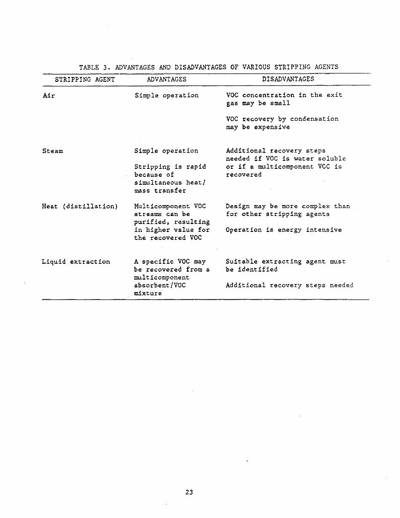
TABLE 3. ADVANTAGES AND DISADVANTAGES OF VARIOUS STRIPPING AGENTS STRIPPING AGENT ADVANTAGES DISADVANTAGES
Air Simple opera t ion
Steam Simple operat ion
S t r ipp ing is rapid because of simultaneous hea t / mass t r a n s f e r
Heat ( d i s t i l l a t i o n ) Multicomponent VOC streams can be p u r i f i e d , r e s u l t i n g i n higher value f o r t h e recovered VOC
Liquid e x t r a c t i o n A s p e c i f i c VOC may be recovered from a multicomponent absorbentlVOC mixture
VOC concent ra t ion i n t h e e x i t gas may be small
VOC recovery by condensation may be expensive
Addit ional recovery s t e p s needed i f VOC is water soluble o r i f a multicomponent VOC is re cove r e d
Design may be more complex than f o r o the r s t r i p p i n g agents
Operation is energy i n t e n s i v e
Su i t ab le e x t r a c t i n g agent must be i d e n t i f i e d
Addit ional recovery s t e p s needed
23
VOC concentration in the inlet gas is also important. Since the entire
gas stream must be cooled to condense the VOC, energy costs can be prohibitive if the VOC concentration is low. Below about 5,000 ppm, recovery by condensation is not usually practical.2 This limit is purely
economic, however, because in principle almost any VOC could be recovered
from a given inlet gas stream.
If the dew point of the inlet gas stream is higher than the coolant
temperature, water will condense along with the VOC. This can cause two
problems-corrosion and low VOC purity. Corrosion will result if the VOC hydrolyzes easily or forms any corrosive compound on contact with liquid
water, such as some chlorinated VOCs do. If the VOC is water soluble or
toxic, condensation of water simultaneously with the VOC will require subsequent VOC-water separation or wastewater treatment to remove the toxic
VOC from any discharged water, respectively. One way to avoid this problem
is to use a desiccant bed (molecular sieves, alumina, or silica gel)
upstream of the condenser (see Kohl and Rei~enfeld,~ p. 630).
VOC removal efficiencies by condensation can be fixed at any level
desired, the only constrairt being cost. If greater than 90% removal must
be achieved, coolants other than cooling water must generally be usedY2 especially if low-molecular-weight VOCs are present.
For inlet gas streams containing more than one VOC, it is possible,
though not normally practical, to design partial condensers in series, each
of which condenses one VOC. This could become practical if the VOCs
differed widely in boiling points, say by at least 75 to 100.F.
Finally, the condensed VOC may form either an aerosol or entrained
If either droplets in the heat exchanger at practical gas velocities.
occurs, the VOC must be recovered by either demisters or a collection
device such as a cyclone. The overall efficiency of the VOC recovery
process (condensation and collection) may be significantly reduced if the
aerosolldroplet size is much less than about 5 pm. This can be solved by
limiting the gas velocity tarough the condenser.
24
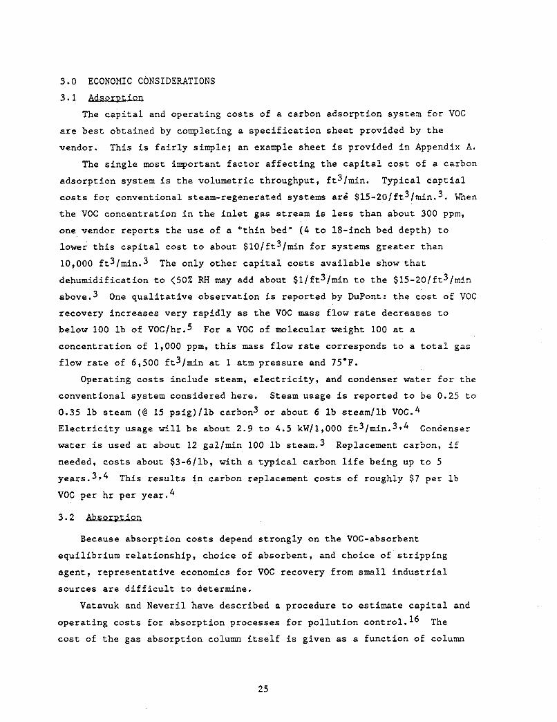
3.0 ECONOMIC CONSIDERATIONS
3.1 Adsorption
The capi ta l and operat ing c o s t s of a carbon adsorpt ion s y s t e m f o r VOC
a r e b e s t obtained by completing a s p e c i f i c a t i o n shee t provided by t h e
vendor. This is f a i r l y simple; an example shee t is provided i n Appendix A.
The s i n g l e most important f a c t o r a f f e c t i n g t h e c a p i t a l c o s t of a carbon
adsorp t ion system is t h e volumetric throughput, f t3/min.
c o s t s f o r conventional steam-regenerated systems a r i $15-20/ft3/min.3. When
t h e VOC concentrat ion i n t h e i n l e t gas s t ream is l e s s than about 300 ppm,
one vendor r epor t s t h e use of a " t h i n bed" ( 4 t o 18-inch bed depth) t o
lower t h i s c a p i t a l cos t t o about $10/ft3/min f o r systems g r e a t e r than
10,000 ft31min.3
dehumidif icat ion t o <50% RH may add about $ l / f t s / m i n t o t h e $15-20/ft3/min
above.3
recovery increases very r ap id ly as t h e VOC mass f low rate decreases t o
below 100 l b of VOC/hr.fi
concent ra t ion of 1,000 ppm, t h i s mass f low r a t e corresponds t o a t o t a l gas
f low r a t e of 6,500 f t3/min a t 1 a t m pressure and 75.F.
Typical c a p t i a l
The only o the r c a p i t a l cos t s a v a i l a b l e show t h a t
One q u a l i t a t i v e observat ion is reported by DuPont: t h e c o s t of VOC
For a VOC of molecular weight 100 a t a
Operating c o s t s include steam, e l e c t r i c i t y , and condenser water f o r t h e
conventional system considered here . Steam usage i s reported t o be 0.25 t o
0.35 Ib steam ( @ 15 p s i g ) / l b carbon3 o r about 6 l b s teaml lb VOC.4
E l e c t r i c i t y usage w i l l be about 2.9 t o 4.5 kW/l,OOO ft3/min.3p4
water is used a t about 12 gal/min 100 l b steam.3
needed, c o s t s about $3-6/lb, with a t y p i c a l carbon l i f e being up t o 5
year^.^^^ VOC per h r p e r year .4
Condenser
Replacement carbon, i f
This r e s u l t s i n carbon replacement c o s t s of roughly $7 per l b
3.2
Because absorpt ion c o s t s depend s t rong ly on t h e VOC-absorbent
equi l ibr ium re l a t ionsh ip , choice of absorbent, and choice of s t r i p p i n g
agent , r ep resen ta t ive economics f o r VOC recovery from small i n d u s t r i a l
sources a r e d i f f i c u l t t o determine.
Vatavuk and Neveri l have descr ibed a procedure t o estimate c a p i t a l and
The opera t ing c o s t s f o r absorpt ion processes f o r p o l l u t i o n cont ro l . l6
c o s t of t h e gas absorpt ion column i t s e l f i s given as a func t ion of column
25
weight and t h e c o s t of pe r iphe ra l support equipment is a l s o given.
However, no s p e c i f i c examples a r e shown.
Zenz g ives a d e t a i l e d design procedure f o r absorp t ion towers, bu t does
not d i scuss economics i n de ta i l .17
and Timerhaus (pp. 768-776) f o r absorpt ion equipment cos t s .6
The reader should a l s o consul t Pe t e r s
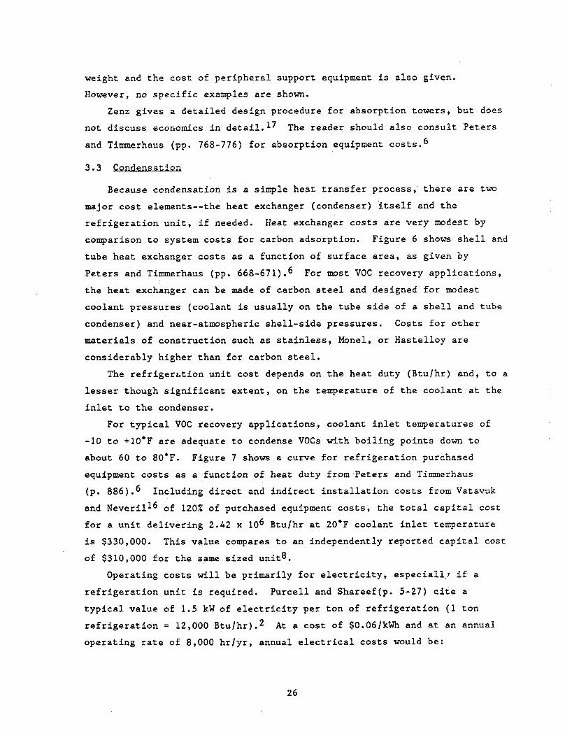
3.3 ! 2 ” a t i o n
Because condensation i s a simple hea t t r a n s f e r process , t h e r e a r e two
major c o s t elements--the hea t exchanger (condenser) i t s e l f and t h e
r e f r i g e r a t i o n u n i t , i f needed.
comparison t o system c o s t s f o r carbon adsorpt ion. Figure 6 shows s h e l l and
tube hea t exchanger c o s t s as a func t ion of su r face a r e a , as given by
Peters and Timerhaus (pp. 668-671) .6
t h e hea t exchanger can be made of carbon s teel and designed f o r modest
coolant p re s su res (coolant i s usua l ly on t h e tube s i d e of a s h e l l and tube
condenser) and near-atmospheric s h e l l - s i d e pressures . Costs f o r o t h e r
materials of cons t ruc t ion such as s t a i n l e s s , Monel, or Has te l loy a r e
considerably higher than f o r carbon steel.
Heat exchanger c o s t s a r e very modest by
For most VOC recovery app l i ca t ions ,
The r e f r i g e r a t i o n u n i t cos t depends on t h e hea t duty (B tu lh r ) and, t o a
l e s s e r though s i g n i f i c a n t ex ten t , on t h e temperature of t h e coolan t a t t he
i n l e t t o the condenser.
For t y p i c a l VOC recovery app l i ca t ions , coolant i n l e t temperatures of
-10 t o 410.F are adequate t o condense VOCs wi th b o i l i n g po in t s down t o
about 60 t o 80.F. Figure 7 shows a curve f o r r e f r i g e r a t i o n purchased
equipment c o s t s as a funct ion of heat duty from Pe te r s and Timmerhaus
(p. 886) .6
and Neveril16 of 120% of purchased equipment c o s t s , t he t o t a l c a p i t a l cos t
f o r a u n i t de l ive r ing 2.42 x 10⁶ Btu/hr a t 20.F coolant i n l e t temperature
is $330,000.
of $310,000 f o r t h e same s i zed uni t8 .
Including d i r e c t and i n d i r e c t i n s t a l l a t i o n c o s t s from Vatavuk
This value compares t o an independently reported c a p i t a l cos t
Operating costs w i l l be pr imar i ly f o r e l e c t r i c i t y , especia1l.r i f a
r e f r i g e r a t i o n u n i t is required. Pu rce l l and Shareef(p. 5-27) c i t e a
t y p i c a l va lue of 1.5 kW of e l e c t r i c i t y per t o n of r e f r i g e r a t i o n (1 t o n
r e f r i g e r a t i o n = 12,000 Btu /hr ) .2
opera t ing r a t e of 8,000 h r / y r , annual e l e c t r i c a l c o s t s would be:
A t a c o s t of $O.O6/kWh and a t an annual
26
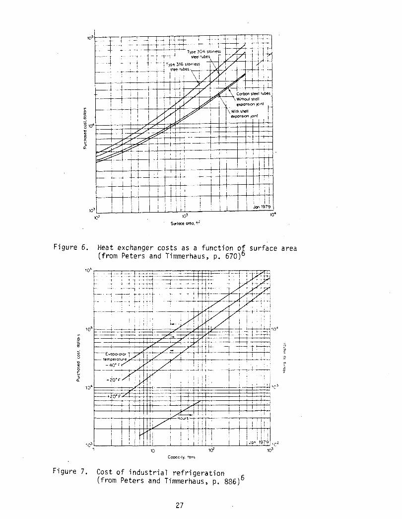
Figure 6. Heat exchanger cos ts a s a function of surface area (from Peters and Timmerhaus, p. 670)6
D x u a" L
Figure 7
1 + + + * *
-4 -
- 0 - .A
5 0 - 4
3 c I
Cawcity, ions
. Cost of indus t r ia l re f r igera t ion (from Peters and Timmerhaus, p. 886)
27
Annual e l e c t r i c a l = costs 1 t on 11 kWh J 1 y r J
f U k W 1 fSO.061 fB000
= $720/yr/ ton r e f r i g e r a t i o n .
Although it is not wi th in t h e scope of t h i s monograph t o present
d e t a i l e d s p e c i f i c comparisons of VOC recovery techniques, t h e r e s u l t s of
one such study8 comparing carbon adsorpt ion and condensation are presented
i n Table 4 . These r e s u l t s support t h e genera l comparisons of Figure 4 .
S p e c i f i c a l l y , t h i s s tudy shows t h a t condensation is not economical a t l o w
VOC concent ra t ion , t h a t condensation i s more c a p i t a l i n t ens ive than
adsorp t ion , and t h a t at t h e h ighes t VOC concent ra t ion examined (8,000 ppm),
condensation is competi t ive wi th adsorpt ion. Also note t h e two opt ions far
use of t h e recovered VOC--either as a so lvent or a f u e l . Re-use as a
so lvent is considerably more economical i n all cases. This s tudy also
concludes t h a t only carbon adsorp t ion is capable of p r a c t i c a l removal
e f f i c i e n c i e s of 954 or g r e a t e r (condensation is assumed t o achieve 90%
t y p i c a l l y ) .
28
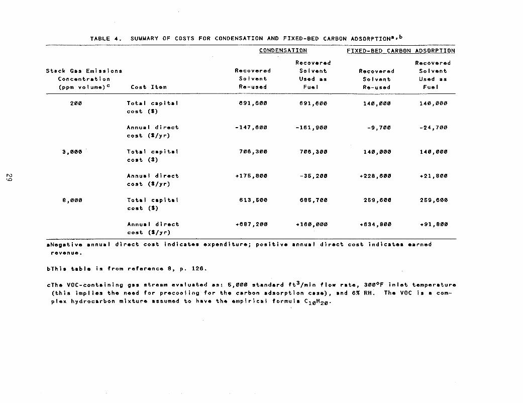
TABLE 4. SUMMARY OF COSTS FOR CONDENSATION AND FIXED-BED CARBON ADSORPTION~J~
CONDENSATION FIXED-BED CARBON ADSORPTION
S t a c k Gas E m i s s i o n s C o n c e n t r a t i o n (ppm v o I ume) C o s t I t e m
R e c o v e r e d R e c o v e r e d So I v e n t R e c o v e r e d So I v e n t
Used a s
Recovered
So I v e n t Used a s So I v e n t Re-used Fue I Re-used Fue I
200
3,000
8,000
T o t a l c a p i t a l c o s t ( 3 )
A n n u a l d i r e c t c o s t ( S / y r )
T o t a l c a p i t a l c o s t ( 3 )
A n n u a l d i r e c t c o s t ( t / y r )
T o t a l C 8 p i t . l
c o s t ( S )
Annua l d i r e c t c o s t ( S / y r)
~~ ~
691,600 691,600 140,000 1 4 0 , 000
-147,600 -161 ,900 -9 , 700 -24,700
706 , 30% 140,000 140,000 706 , 308
+228,600 +21 , 800 +176,800 -35 , 200
259,800 613 , 600 685,700 259 , 600
+687,200 +l60,000 +634,800 +91,800
. N e g a t i v e a n n u a l d i r e c t c o s t i n d i c a t e s e x p e n d i t u r e ; p o s i t i v e a n n u a l d i r e c t c o s t i n d i c a t e s e a r n e d r e v e n u e .
b T h l s t a b l e I s f r o m r e f e r e n c e 8, p. 126.
cThe V O C - c o n t a i n i n g g a s s t r e a m e v a l u a t e d as : 5,000 s t a n d a r d f t 3 / m i n flow r a t e , 300OF i n l e t t e m p e r a t u r e ( t h i s i m p l i e s t h e need f o r p r e c o o l i n g f o r t h e c a r b o n a d s o r p t i o n c a s e ) , and 6% R H . The VOC i s a com- p l e x h y d r o c a r b o n m i x t u r e assumed t o h a v e t h e e m p i r i c a l f o r m u l a C10H20.
4.0 VENDORS
This s e c t i o n i s a noncomprehensive l i s t of some vendors of systems for
The reader should consul t chemical equipment ca t a logs f o r a VOC recovery.
more complete l i s t i n g .
Table 5 provides a l i s t of vendors of ac t iva t ed carbon systems f o r Vcv",
recovery.
4.2 &sorpt ion
There a r e no known vendors of absorpt ion systems f o r VOC recovery f r m
small i n d u s t r i a l sources. However, absorp t ion is an extremely widespread
technology f o r ac id gas removal and o the r p o l l u t i o n con t ro l appl ica t ions-
The i n t e r e s t e d reader should consul t a d i r ec to ry of chemical equipment
vendors under t h e heading "Absorbers" or "Scrubbers. 'I Some vendors in t hese l i s t i n g s include:
Croll-Reynolds Co., Inc. 7 5 1 Cent ra l Ave. P.O. Box 668 Westf ie ld , NJ 07901 201-232-4200
D i s t i l l a t i o n Engineering Co., Inc. 105 Dorsa Ave. Livingston, NJ 07039 201-992-9600
Koch Engineering Co., Inc. 171 Rel ley Ave. P.O. Box 109 Akron, OH 44309 216-724-1277
O t t o York Co. 42' I n t e r v a l e Rd. P.O. Box 3100 Parsipany, NJ 07054 201-299-9200
30
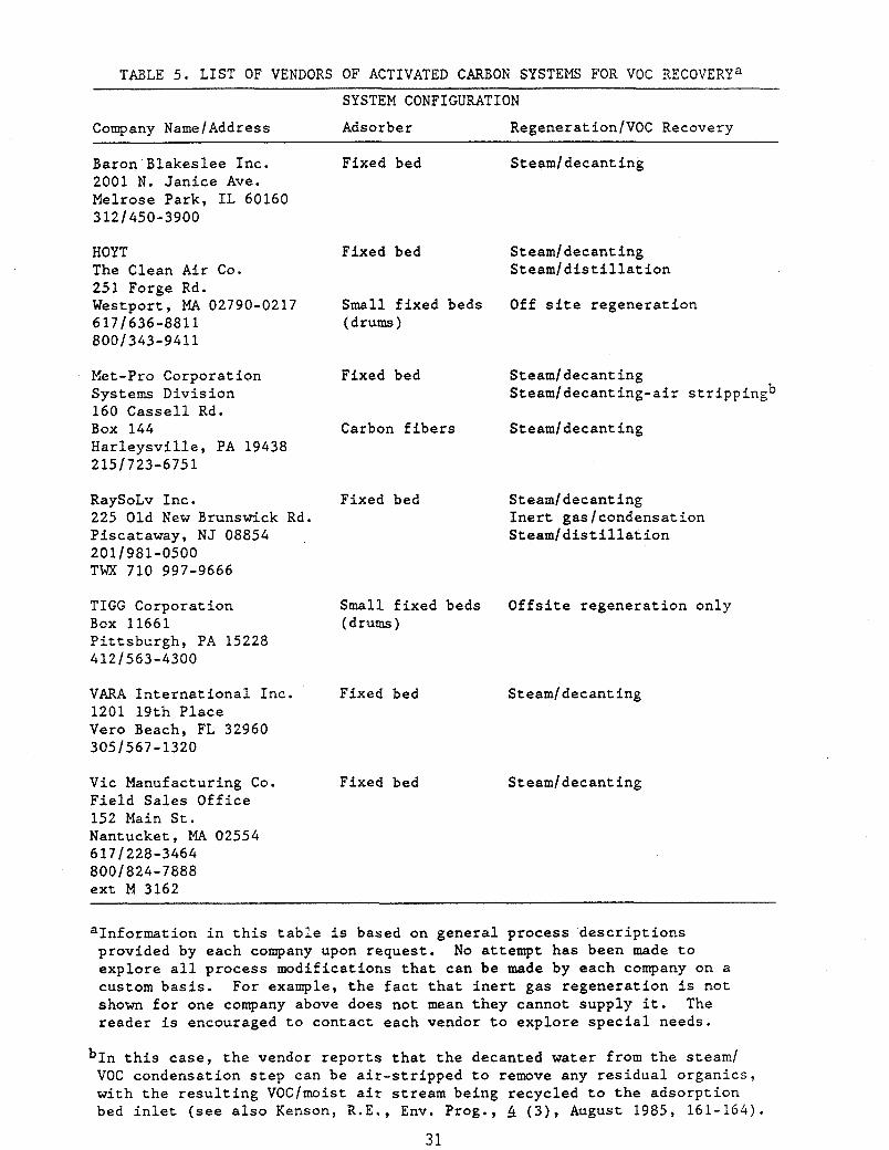
TABLE 5 . LIST OF VENDORS OF ACTIVATED CARBON SYSTEMS FOR VOC RECOVERYa SYSTEM CONFIGURATION
Company NameIAddress Adsorb e r RegenerationlVOC Recovery
Baron Blakeslee Inc. 2001 N. Janice Ave. Melrose Park, IL 60160 3121450-3900
Fixed bed Steamldecanting
HOY T The Clean Air Co. 251 Forge Rd. Westport, MA 02790-0217 6 17 1636-881 1 800/343-9411
Met-Pro Corporation Systems Division 160 Cassell Rd. Box 144 Harleysville, PA 19438 2151723-6751
RaySoLv Inc. 225 Old New Brunswick Rd. Piscataway, NJ 08854 2011981-0500 TWX 710 997-9666
TIGG Corporation Box 11661 Pittsburgh, PA 15228 4121563-4300
VARA International Inc. 1201 19th Place Vero Beach, FL 32960 3051567-1320
Vic Manufacturing Co. Field Sales Office 152 Main St. Nantucket, MA 02554 6171228-3464 8001824-7888 ext M 3162
Fixed bed
Small fixed beds (drums)
Fixed bed
Carbon fibers
Fixed bed
Steamldecanting Steamldistillation
Off site regeneration
Steamldecanting Steamldecant ing-air s t ripp ingb
Steamldecanting
Steamldecanting Inert gaslcondensation Steam/distillation
Small fixed beds Offsite regeneration only (drums)
Fixed bed
Fixed bed
Steamldecanting
Steamldecanting
aInformation in this table is based on general process descriptions provided by each company upon request. explore all process modifications that can be made by each company on a custom basis. For example, the fact that inert gas regeneration is not shown for one company above does not mean they cannot supply it. The reader is encouraged to contact each vendor to explore special needs.
No attempt has been made to
this case, the vendor reports that the decanted water from the steam/ VOC condensation step can be air-stripped to remove any residual organics, with the resulting VOCImoist air stream being recycled to the adsorption bed inlet (see also Kenson, R.E., Env. Prog., 4 ( 3 ) , August 1985, 161-164).
31
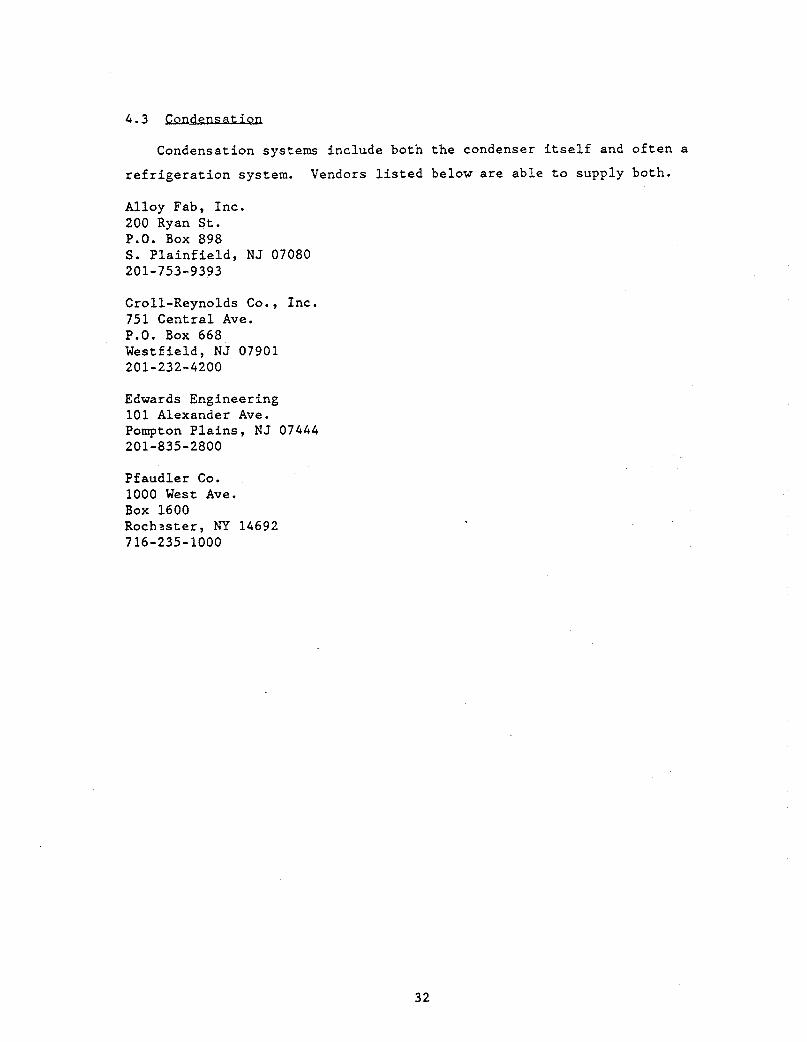
4.3 Condensation
Condensation systems include both the condenser itself and often a
refrigeration system. Vendors listed below are able to supply both.
Alloy Fab, Inc. 200 Ryan St. P.O. Box 898 S. Plainfield, NJ 07080 201-753-9393
Croll-Reynolds Co., Inc. 751 Central Ave. P.O. Box 668 Westfield, NJ 07901 201-232-4200
Edwards Engineering 101 Alexander Ave. Pompton Plains, NJ 07444 201-835-2800
Pfaudler Co. 1000 West Ave. Box 1600 Roch?ster, NY 14692 716-235-1000
32
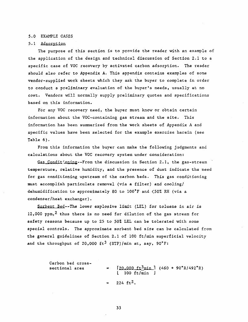
5.0 EXAMPLE CASES 5.1 Adsorption
The purpose of this section is to provide the reader with an example of
the application of the design and technical discussion of Section 2.1 to a
specific case of VOC recovery by activated carbon adsorption.
should also refer to Appendix A. This appendix contains examples of some vendor-supplied work sheets which they ask the buyer to complete in order
to conduct a preliminary evaluation of the buyer's needs, usually at no
cost. Vendors will normally supply preliminary quotes and specifications
based on this information.
The reader
For any VOC recovery need, the buyer must know or obtain certain
information about the VOC-containing gas stream and the site. This
information has been summarized fromthe work sheets of Appendix A and specific values have been selected for the example exercise herein (see
Table 6). From this information the buyer can make the following judgments and
calculations about the VOC recovery system under consideration:
a s ConrKT4.Qnixlg--From the discussion in Section 2.1, the gas-stream '
temperature, relative humidity, and the presence of dust indicate the need for gas conditioning upstream of the carbon beds. This gas conditioning
must accomplish particulate removal (via a filter) and cooling,'
dehumidification to approximately 80 to lOO'F and <50% RH (via a condenser/heat exchanger).
Sorbent- - The lower explosive limit (LEL) for toluene in air is 12,000 ppm,2 thus there is no need for dilution of the gas stream for
safety reasons because up to 25 to 50% LEL can be tolerated with some special controls. The approximate sorbent bed size can be calculated from
the general guidelines of Section 2.1 of 100 ft/min superficial velocity and the throughput of 20,000 ft3 (STP)/min at, say, 90'F:
Carbon bed cross- sectional area = r m 2 m i n i (460 + 90°R/492'R)
1 100 ftlmin J
= 224 ft2.
33
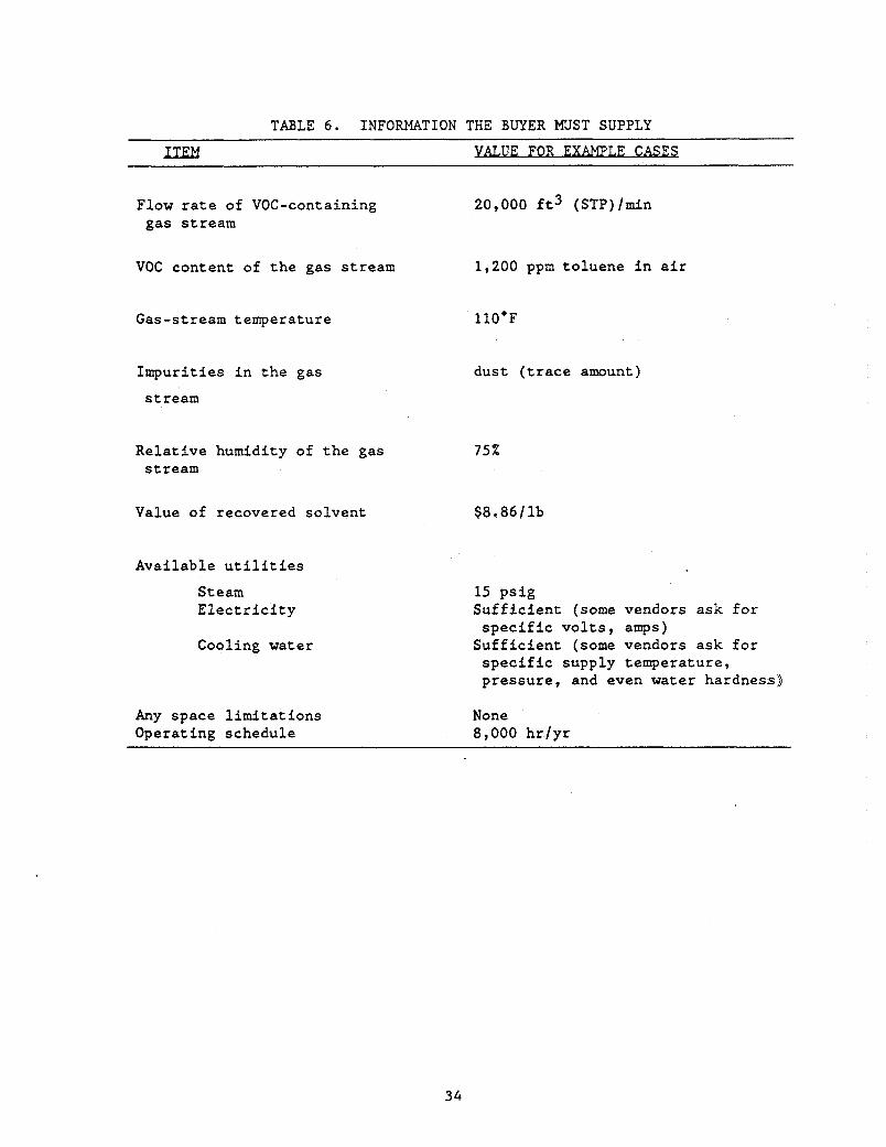
TABLE 6. INFORMATION THE BUYER MUST SUPPLY
LTm FOR E W L E C A S U
Flow rate of VOC-containing gas stream
20,000 ft3 ( ~ ~ ~ ) / m i n
VOC content of the gas stream 1,200 ppm toluene in air
Gas-stream temperature 110.F
Impurities in the gas
stream
dust (trace amount)
Relative humidity of the gas 75% stream
Value of recovered solvent $8,86/ lb
Available utilities
Steam Electricity
Cooling water
15 psig Sufficient (some vendors ask for
Sufficient (some vendors ask for specific volts, amps)
specific supply temperature, pressure, and even water hardness)
Any space limitations None Operating schedule 8,000 hr/yr
34
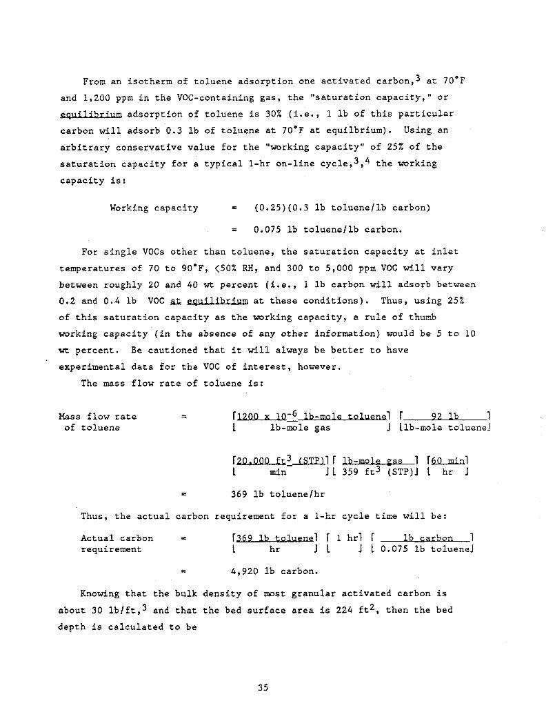
From an isotherm of toluene adsorpt ion one ac t iva t ed carbon,3 a t 70'F
and 1,200 ppm i n t h e VOC-containing gas, t h e " sa tu ra t ion capac i ty , " o r
adsorpt ion of toluene is 30% ( i - e . , 1 l b of t h i s p a r t i c u l a r . . . carbon w i l l adsorb 0.3 l b of toluene a t 70°F a t equi lbr ium).
a r b i t r a r y conservat ive value f o r t h e "working capac i ty" of 25% of t h e
s a t u r a t i o n capac i ty f o r a t y p i c a l l -hr on- l ine ~ y c l e , 3 , ~ t h e working
capac i ty i s :
Using an
Working capac i ty = (0.25)(0.3 l b to luene l lb carbon)
= 0.075 l b to luene l lb carbon.
For s i n g l e VOCs o the r than toluene, t h e s a t u r a t i o n capac i ty a t i n l e t
temperatures of 70 t o 90°F, <SO% RH, and 300 t o 5,000 ppm VOC w i l l vary
between roughly 20 and 40 w t percent ( i . e . , 1 l b carbon w i l l adsorb between
0.2 and 0.4 l b VOC a t t h e s e cond i t ions ) . Thus, using 25%
of t h i s s a t u r a t i o n capac i ty a s t h e working capac i ty , a r u l e of thumb
working capac i ty ( i n the absence of any o the r information) would be 5 t o 10
w t percent . Be cautioned t h a t it w i l l always be b e t t e r t o have
experimental da t a f o r t h e VOC of i n t e r e s t , however.
The mass f low r a t e of toluene is:
Mass f low r a t e - - rl-Qz l b -mo 1 e t o 1ue.n.e i r 92 1 b 1 of to luene 1 lb-mole gas J Llb-mole toluenel
ra-?mli r m e cas 1 r-i 1 min J 1 359 f t 3 (STP)J L h r J
= 369 l b to luene /hr
Thus, t h e a c t u a l carbon requirement f o r a l -h r cyc le time w i l l be:
Actual carbon = r369 l b toluene1 F 1 h r l r l b carbon 1 requirement 1 h r J L J 1 0.075 l b toluenel
4,920 l b carbon.
Knowing t h a t t h e bulk dens i ty of most g ranular ac t iva t ed carbon i s
about 30 l b / f t , 3 and t h a t t h e bed su r face a rea is 224 f t 2 , then t h e bed
depth is ca l cu la t ed t o be
35
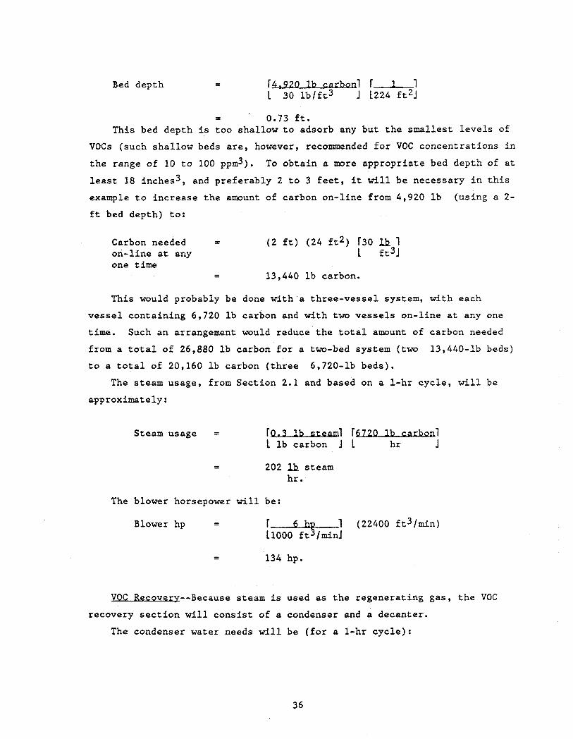
Bed depth F4.920 ,B carbon1 F-1 1 30 l b / f t 3 J 1224 f t 2 J
- - ’ 0.73 f t . This bed depth is too shal low t o adsorb any but t h e smal les t l e v e l s of
VOCs (such sha l low beds a r e , however, recommended f o r VOC concent ra t ions i n
t h e range of 10 t o 100 ppm3). To ob ta in a more appropr ia te bed depth of a t
least 18 inches3, and preferab ly 2 t o 3 f e e t , it wil l be necessary i n t h i s
example t o inc rease t h e amount of carbon on-l ine from 4,920 l b
f t bed depth) t o :
(us ing a 2-
Carbon needed - - ( 2 f t ) (24 f t 2 ) r30 1 on-l ine a t any 1 f t3J one time
- - 13,440 l b carbon.
This would probably be done with a three-vesse l system, with each
v e s s e l conta in ing 6,720 l b carbon and wi th two v e s s e l s on- l ine a t any one
t i m e . Such an arrangement would reduce t h e t o t a l amount of carbon needed
from a t o t a l of 26,880 l b carbon f o r a two-bed system ( t w o
t o a t o t a l of 20,160 l b carbon ( t h r e e 6,720-1b beds) .
13,440-1b beds)
The steam usage, from Sect ion 2 .1 and based on a 1-hr cyc le , w i l l be
approximately:
Steam usage = rp.3 l b s t e a l r5720 l b caEhan1 1 l b carbon J 1 h r J
= 202 lk steam hr .
The blower horsepower w i l l be:
1 (22400 f t3/min) r* - Blower hp -
LIOOO f t lminl
VOC Recovery--Because steam is used as t h e regenera t ing gas , t h e VOC
recovery s e c t i o n will c o n s i s t of a condenser and a decanter .
The condenser water needs w i l l be ( f o r a 1-hr cyc le ) :
36
Condenser water = 1 1 (202 l b steam) f low 1100 l b s t e a d
= 24 gallmin
One poin t of cau t ion is t h a t f o r t h i s p a r t i c u l a r case , t h e aqueous
s o l u b i l i t y of t h e VOC i n water is neg l ig ib l e .
recovered d i r e c t l y and re-used o r so ld and t h e decanted w a t e r is probably
s u i t a b l e f o r b o i l e r o r condenser feed. This may not be t r u e i n some
app l i ca t ions and t h e buyer should be c a r e f u l t h a t t h e recovered VOC i s not
unduly contaminated with water, nor t h e water with VOC. The presence of
such cross-contamination, even a t f a i r l y small l e v e l s , can d r a s t i c a l l y
a f f e c t t h e economics of VOC recovery.
Thus t h e VOC can be
J ? c o a - - B a s e d on the rough guidance of Sec t ion 3.1, t h e c a p i t a l cos t
of t h e e n t i r e system is about
Cap i t a l c o s t = I' ~ 2 0 1 (22,400 f t3 /min) L ft3/minJ
- - $44 3,000.
Carbon c o s t ( m u d e d i n t h e above c a p i t a l c o s t ) w i l l be ( a t $4 / lb ) :
Carbon cos t = ($4/1b)(20,160 l b carbon)
- - $80,640.
A 5 t o 10-year t y p i c a l carbon l i f e implies a 10 t o 20%/year carbon
replacement c o s t , o r $8,100 t o $16,20O/yr,
Annual e l e c t r i c a l c o s t s a t $0.06/kWh and 4 kW/l,OOO ft3/min and 8,000
h r / y r opera t ion w i l l be:
Annual e l e c t r i c i t y = ~ S O O O hrl r $ m 1 r 4 kw 1(22,400 f t3 lmin) c o s t I yrJ 1 kWh J 11000 ft3/minJ
t $43,000.
Annual steam cos t ( a t $1/1000 l b ) w i l l be:
Steam c o s t s = r202 181 r8000 hrf r SI 1 1 hrJ 1 y r J 11000 1bJ
37
Annual condenser water cos t ( a t $0.15/1000 g a l ) w i l l be:
Annual condenser = r u e a l l r5-m 80001 r sui 1 water c o s t 1 min J 1 h r J L y r ’ J 11000 ga l l
= $1,700.
There w i l l be a c r e d i t f o r t h e recovered VOC as w e l l . Assuming 95%
o v e r a l l e f f i c i e n c y and a value of $8.861100 l b f o r to luene ,6 t h i s annual
c r e d i t w i l l be:
VOC recovery = fSs.86 1 r0.951 r369 l b l f 8 0 0 0 h r l c r e d i t 1100 l b l 1 J 1 h r j 1 y r J
= $248,500.
I n summary f o r t h i s case , t h e c o s t s w i l l be roughly:
C a p i t a l c o s t $448,000 Annual opera t ing c o s t
Carbon replacement 8,100 - 16,200 E l e c t r i c i t y 43 , 000 Steam 1,600 Condenser water 1,700
Annual opera t ing c r e d i t $248,500.
To t h e annual opera t ing c o s t s must be added d i r e c t and i n d i r e c t l abor
and related i n d i r e c t annual expenses ( taxes , insurance, e t c . ) . The c a p i t a l
c o s t must be amortized and a f i n a l c o s t (o r c r e d i t ) i n $ /y r determined.
This exe rc i se is s p e c i f i c t o each small i n d u s t r i a l u s e r and is not completed
here in .
f o r such an evaluat ion.
However, t h e above should provide t h e user wi th a s t a r t i n g poin t
Although VOC recovery by absorpt ion is not widely p rac t i ced , some
examples of i t s use are s i m i l a r t o VOC recovery.
recovery of aromatics from coke-oven gas using a heavy hydrocarbon absorbent
known a s wash o i l .
t o t h e 1880s i n t h e United S t a t e s and was used t o recover t h e r e l a t i v e l y
va luable benzene, toluene and xylene from t h e coa l coking processes a s i n
s teel p l a n t s .
One such example is t h e
S t r ipp ing is done by steam. This opera t ion d a m s back
38
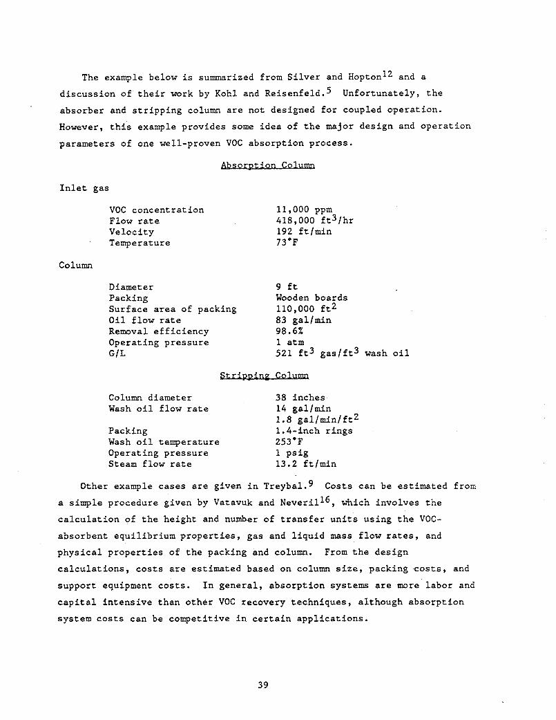
The example below i s summarized from S i l v e r and Hopton12 and a
d iscuss ion of t h e i r work by Kohl and R e i ~ e n f e l d . ~ Unfortunately, t h e
absorber and s t r i p p i n g column a r e not designed f o r coupled operat ion.
However, t h i s example provides some idea of t h e major design and opera t ion
parameters of one well-proven VOC absorpt ion process.
I n l e t gas
VOC concentrat ion Flow r a t e Veloci ty Temperature
11,000 ppm 418,000 f t 3 l h r 192 f t lmin 73OF
Column
D iame t e r 9 f t Packing Wooden boards Surface a r e a of packing O i l f low r a t e 83 gallmin Removal e f f i c i e n c y 98.6% Operating pressure 1 a t m GIL
110,000 f t 2
521 f t 3 g a s / f t 3 wash o i l
Column diameter 38 inches Wash o i l f low r a t e
Packing 1.4-inch r ings Wash o i l temperature 253.F Operating pressure 1 p s i g Steam f low r a t e 13.2 f t l m i n
14 gallmin 1.8 g a l l m i n / f t 2
Other example cases a r e given i n Treybal.9 Costs can be est imated from
a simple procedure given by Vatavuk and Neveril16, which involves t h e
c a l c u l a t i o n of t h e height and number of t r a n s f e r u n i t s using t h e VOC-
absorbent equi l ibr ium p rope r t i e s , gas and l i q u i d mass f low rates, and
phys ica l p rope r t i e s of t h e packing and column.
c a l c u l a t i o n s , c o s t s are est imated based on column s i z e , packing c o s t s , and
support equipment cos t s . I n genera l , absorp t ion systems are more labor and
c a p i t a l i n t ens ive than o the r VOC recovery techniques, although absorp t ion
system c o s t s can be competit ive i n c e r t a i n app l i ca t ions .
From t h e design
39
5.3
The following example is taken from Purcell and Shareef (p. 4.7-lf.) and demonstrates the condensation of a VOC from a stream typical of one to which this technique can be applied--relatively low flow rate and high VOC c0ncentration.l
For this case, we assume the following:
Inlet gas flow rate Inlet gas temperature 9O0F voc styrene VOC concentration 13,000 ppm Moisture content negligible* Condenser operating pressure 1 atm
2000 ft3 (STP)/min
Removal efficiency required 90%
If the dew point of the inlet gas were close to the dew point of the VOC, then a desiccant might be necessary upstream of the condenser (see Section
*
2.3)
The key variable above is the required removal efficiency. To achieve
90% removal (i.e., an outlet concentration of 1,300 ppm), the temperature
of the gas stream must be reduced at least below that at which the
equilibrium vapor pressure of styrene in air at 1 atm is (1,300 x (760
mm Hg), or 1.0 mm Hg. knowledge of the equilibrium vapor pressure-temperature behavior for the
VOC(s) of interest is required.)
This temperature is 20.F for styrene. (In general,
Because a coolant temperature of at most 20°F is needed, refrigerated
coolant fluid is used. This is usually a "brine" solution, which can be
simply water with an appropriate antifreeze added (CaC12 is selected for the example case2).
The condenser heat load is calculated by a straightforward heat balance on the inlet and exit gas.
Condenser heat = 241,000 Btulhr. load
The condenser surface area is given by the basic design equation of
Section 2.3 ( Q = U A AT). Assuming a countercurrent shell and tube
40
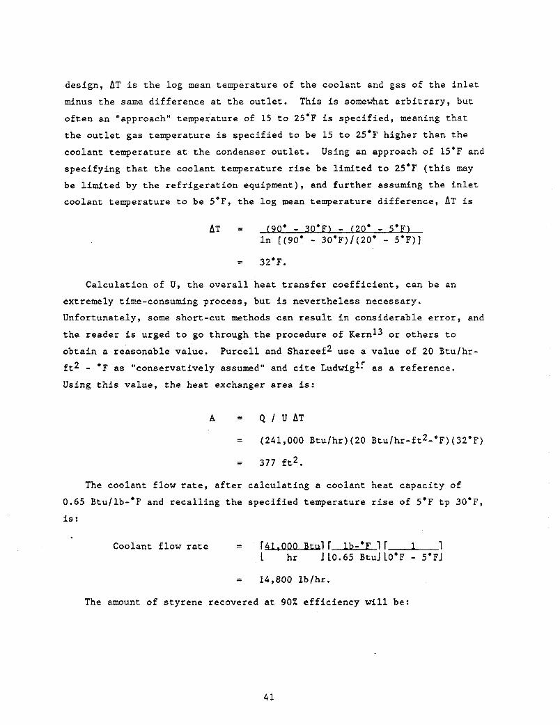
design, AT is t h e log mean temperature of t h e coolant and gas of t h e i n l e t
minus t h e s a m e d i f f e rence a t t h e o u t l e t . This is somewhat a r b i t r a r y , but
o f t e n an "approach" temperature of 15 t o 25'F is s p e c i f i e d , meaning t h a t
t h e o u t l e t gas temperature is spec i f i ed t o be 15 t o 25'F higher than t h e
coolant temperature a t t h e condenser o u t l e t .
spec i fy ing t h a t t h e coolant temperature rise be l imi t ed t o 25'F ( th i s may
be l imi t ed by t h e r e f r i g e r a t i o n equipment), and f u r t h e r assuming t h e i n l e t
coolant temperature t o be 5*F, t h e log mean temperature d i f f e rence , AT is
Using an approach of 15*F and
0 AT = (90" - 30 'E') - (20" - I n [ (90' - 30'F)/(20° - 5'F) J
= 32'F.
Calcu la t ion of U, t h e o v e r a l l hea t t r a n s f e r c o e f f i c i e n t , can be an
extremely time-consuming process , but is never the less necessary.
Unfortunately, some shor t -cu t methods can r e s u l t i n considerable e r r o r , and
t h e reader is urged t o go through t h e procedure of Kern13 o r o the r s t o
ob ta in a reasonable value.
f t 2 - 'F as "conservat ively assumed" and c i te Ludwig1: as a reference.
Using t h i s value, t h e heat exchanger a rea is:
Purce l l and Shareef2 use a va lue of 20 Btu/hr-
A = Q I U A T
= (241,000 Btu /hr ) (20 Btu/hr-ft2-'F) (32°F)
= 377 f t 2 .
The coolant f l o w r a t e , a f t e r ca l cu la t ing a coolant hea t capac i ty of
0.65 Btullb-'F and r e c a l l i n g t h e spec i f i ed temperature r i s e of 5'F t p 30'F,
i s :
Coolant f low rate = f4L.000 Btul r lb-'F 1 r 1 1 1 hr J10.65 BtuJLO'F - 5"FJ
= 14,800 l b /h r .
The amount of s ty rene recovered a t 905b e f f i c i e n c y w i l l be:
41
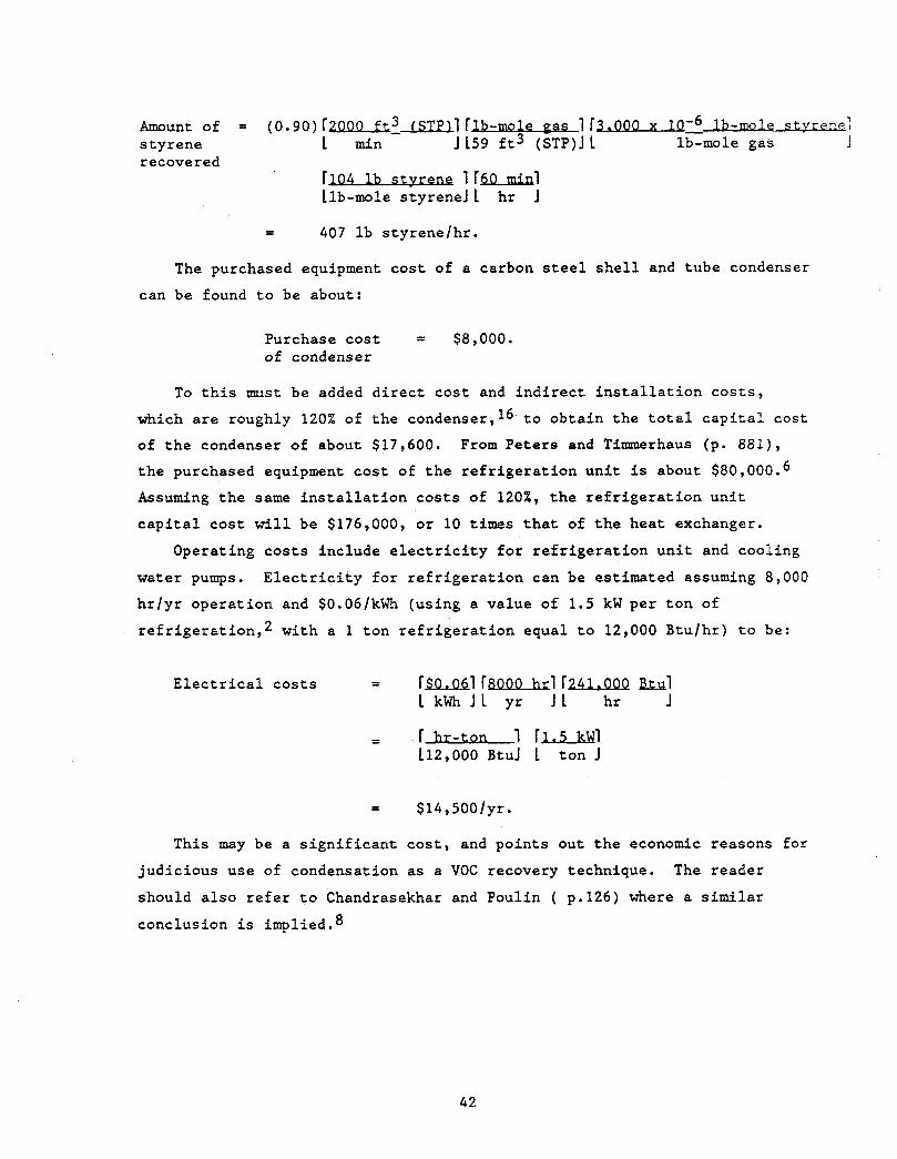
Amount of = (0.90)fZOOO f~~ tSTl!).lfB-mole i r ~ z ib-moie stvr enel
r ecove red styrene L min 1159 ft3 (%I L lb-mole gas 1
i r u i r v klb-mole styreneJ L hr 1
- - 407 lb styrene/hr.
The purchased equipment cost of a carbon steel shell and tube condenser
can be found to be about:
Purchase cost = $8,000. of condenser
To this must be added direct cost and indirect installation costs, which are roughly 120% of the condenser,16 to obtain the total capital cost of the condenser of about $17,600. From Peters and Tinrmerhaus (p. 881), the purchased equipment cost of the ref rigeration unit is about $80,000.
Assuming the same installation costs of 1203, the refrigeration unit capital cost will be $176,000, or 10 times that of the heat exchanger.
Operating costs include electricity for refrigeration unit and cooling
water pumps. hr/yr operation and $O.Od/kWh (using a value of 1.5 kWper ton of refrigeration,2 with a 1 ton refrigeration equal to 12,000 Btulhr) to be:
Electricity for refrigeration can be estimated assuming 8,000
Electrical costs = rs0.0ci FSOOO~~ r z w hi 1 kWhJL yr 1 1 hr J
- - r hr-ton 1 r l a w i 112,000 BtuJ 1 ton J
= $14,50O/yr.
This may be a significant cost, and points out the economic reasons for
judicious use of condensation as a VOC recovery technique. The reader
should also refer to Chandrasekhar and Poulin ( p.126) where a similar
conclusion is implied.8
42
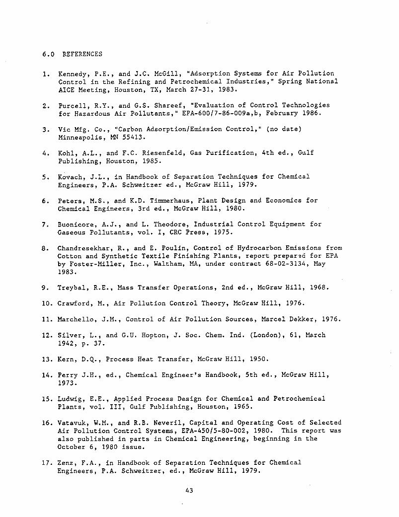
6.0 REFERENCES
1. Kennedy, P.E., and J.C. McGi11, "Adsorption Systems for Air Pollution Control in the Refining and Petrochemical Industries," Spring National AICE Meeting, Houston, TX, March 27-31, 1983.
2 . Purcell, R.Y., and G.S. Shareef, "Evaluation of Control Technologies for Hazardous Air Pollutants," EPA-600/7-86-009a,b, February 1986.
3 . Vic Mfg. Co., "Carbon AdsorptionlEmission Control," (no date) Minneapolis, MN 55413.
4 . Kohl, A.L., and F.C. Riesenfeld, Gas Purification, 4th ed., Gulf Publishing, Houston, 1985.
5 . Kovach, J.L., in Handbook of Separation Techniques for Chemical Engineers, P.A. Schweitzer ed., McGraw Hill, 1979.
6. Peters, M.S., and K.D. Timmerhaus, Plant Design and Economics for Chemical Engineers, 3rd ed., McGraw Hill, 1980.
7. Buonicore, A.J., and L. Theodore, Industrial Control Equipment for Gaseous Pollutants, vol. I, CRC Press, 1975.
8 . Chandresekhar, R., and E. Poulin, Control of Hydrocarbon Emissions from Cotton and Synthetic Textile Finishing Plants, report prepar3d for EPA by Foster-Miller, Inc., Waltham, MA, under contract 68-02-3134, May 1983.
9 . Treybal, R.E., Mass Transfer Operations, 2nd ed., McGraw Hill, 1968.
10. Crawford, M., Air Pollution Control Theory, McGraw Hill, 1976.
11. Marchello, J.M., Control of Air Pollution Sources, Marcel Dekker, 1976.
12. Silver, L., and G.U. Hopton, J. SOC. Chem. Ind. (London), 61, March 1942, p. 37.
13. Kern, D.Q., Process Heat Transfer, McGraw Hill, 1950.
14. Perry J.H., ed., Chemical Engineer's Handbook, 5th ed., McGraw Hill, 1973.
15. Ludwig, E.E., Applied Process Design for Chemical and Petrochemical Plants, vol. 111, Gulf Publishing, Houston, 1965.
16. Vatavuk, W.M., and R.B. Neveril, Capital and Operating Cost of Selected Air Pollution Control Systems, EPA-450/5-80-002, 1980. This report was also published in parts in Chemical Engineering, beginning in the October 6 , 1980 issue.
17. Zenz, F.A., in Handbook of Separation Techniques for Chemical Engineers, P.A. Schweitzer, ed., McGraw Hill, 1979.
43
Appendix A
VENDOR WORKSHEETS FOR CARBON ADSORPTION SYSTEMS
44
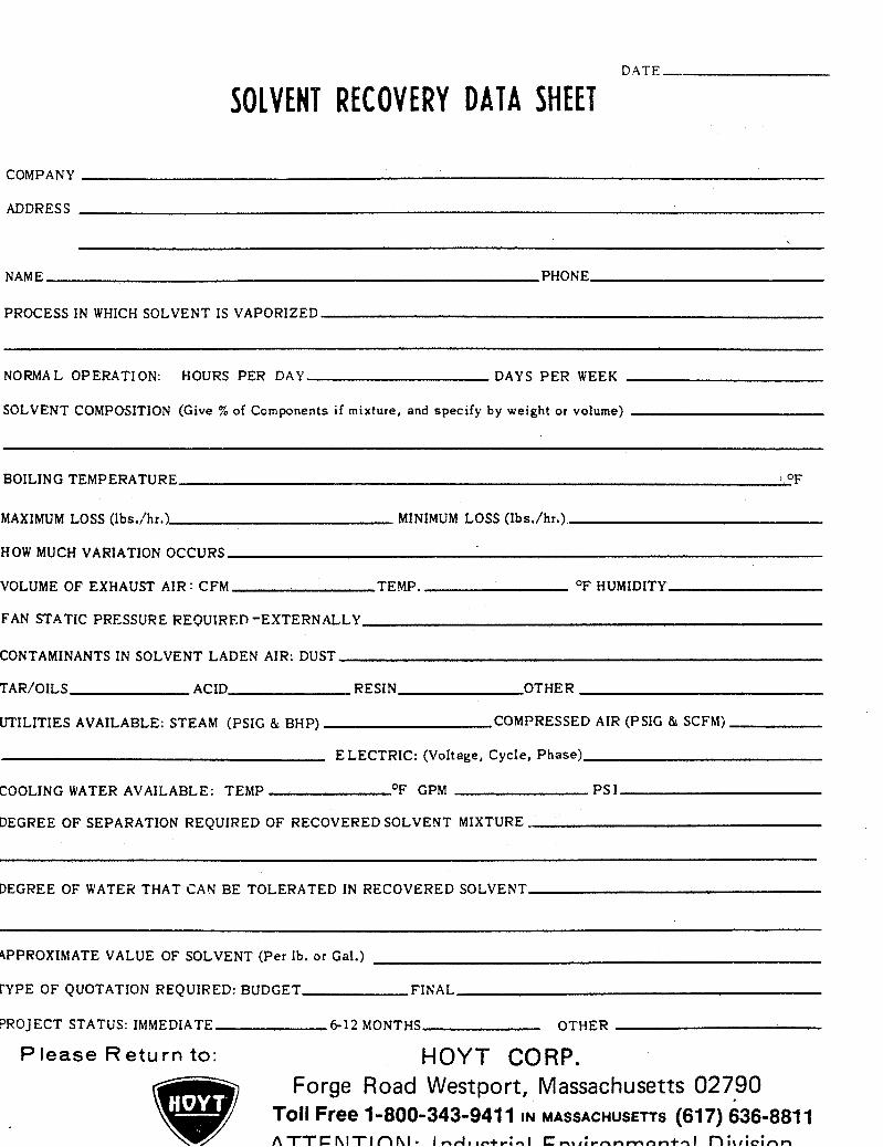
DATE-
SOLVENT RECOVERY DATA SHEET
COMPANY
ADDRESS
~~
NAME PHONE
PROCESS I N WHICH SOLVENT IS VAPORIZED
NORMAL OPERATION: HOURS PER DAY DAYS PER WEEK
SOLVENT COMPOSITION (Give % of Components if mixture, and specify by weight or volume)
BOILING TEMPERATURE OF
MAXIMUM LOSS ( I b d h r . )
HOW MUCH VARIATION OCCURS
VOLUME OF EXHAUST AIR : CFM TEMP. O F HUMIDITY
FAN STATIC PRESSURE REQUIREP -EXTERNALLY
CONTAMINANTS IN SOLVENT LADEN AIR: DUST
TAR/OILS ACID RESIN OTHER
UTILITIES AVAILABLE: STEAM (PSIG & BHP)
MINIMUM LOSS (Ibs./hr.)
COMPRESSED AIR (PSIG & SCFM)
ELECTRIC: (Voltage, Cycle, Phase)
COOLING WATER AVAILABLE: TEMP O F GPM PS I
DEGREE OF SEPARATION REQUIRED OF RECOVERED SOLVENT MIXTURE
DEGREEOF WATERTHATCANBE TOLERATEDINRECOVEREDSOLVENT
4PPROXIMATE VALUE OF SOLVENT (Per Ib. or Gal.)
rYPE O F QUOTATION REQUIRED: BUDGET FINAL
PROJECT STATUS: IMMEDIATE 6 1 2 MONTHS OTHER
P lease R e t u r n to: HOYT CORP. Forge Road Westport, Massachusetts 02790
Toll Free 1-800-343-941 1 IN MASSACHUSETTS (61 7) 636-881 1 A T T C h I T I n h I . l . - .Aa.a+-:Al C-..:unnmnn+nl n : t # L : f i m
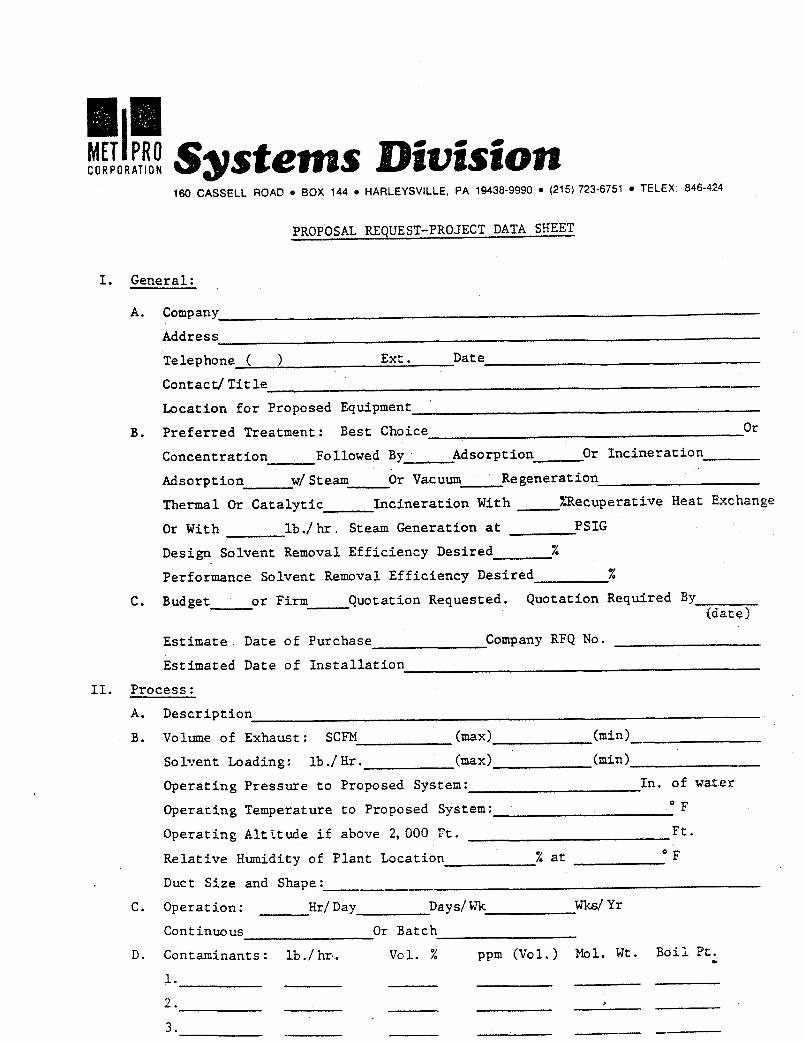
- 160 CASSELL ROAD BOX 144 HARLEYSVILLE, PA 1943&9990 (215) 723-6751 TELEX: 846-424
PROPOSfi REQUEST-PROJECT DATA SHEET
I. General:
A. Company
Address Telephone ( 1 Ext . Date
Contact/ T i t le
Location f o r Proposed Equipment '
B. P re fe r r ed Treatment: Best Choice
Concentrat ion Followed By
Adsorption w/ Steam O r Vacuum Re generat i o n
Thermal O r C a t a l y t i c Inc ine ra t ion With %Recuperative Heat Exchange
O r With l b . / h r , Steam Generation at PSIG
O r
Adsorption O r Inc ine ra t ion
Design Solvent Removal Ef f ic iency Desired
Performance Solvent Removal Ef f ic iency Desired
%
x C. Budget o r Firm Quotation Requested. Quota t ion Required By
{date)
E s t i m a t e Date of Purchase Company RFQ No.
Estimated Date of I n s t a l l a t i o n
11. Process:
A. Descr ip t ion
B. Volume of Exhaust: SCFM (mad (=in)
SolTTent Loading: l b ./ H r . ( m i d
Operacing Temperature t o Proposed System:
Re la t ive Humidity of P lan t Location % at OF
Operating Pressure t o Proposed System: In. of water
O F
F t . Operating Al t i t ude i f above 2, 000 rt.
Duct S ize and Shape:
C. Operation: H r / Day Days/ Wk wks/ Yr
D. Contaminants: l b . / h r . V O l . % ppm (Vol.) Mol. W t . B o i l Pt.
Continuous O r Batch
1.
2.
3 .
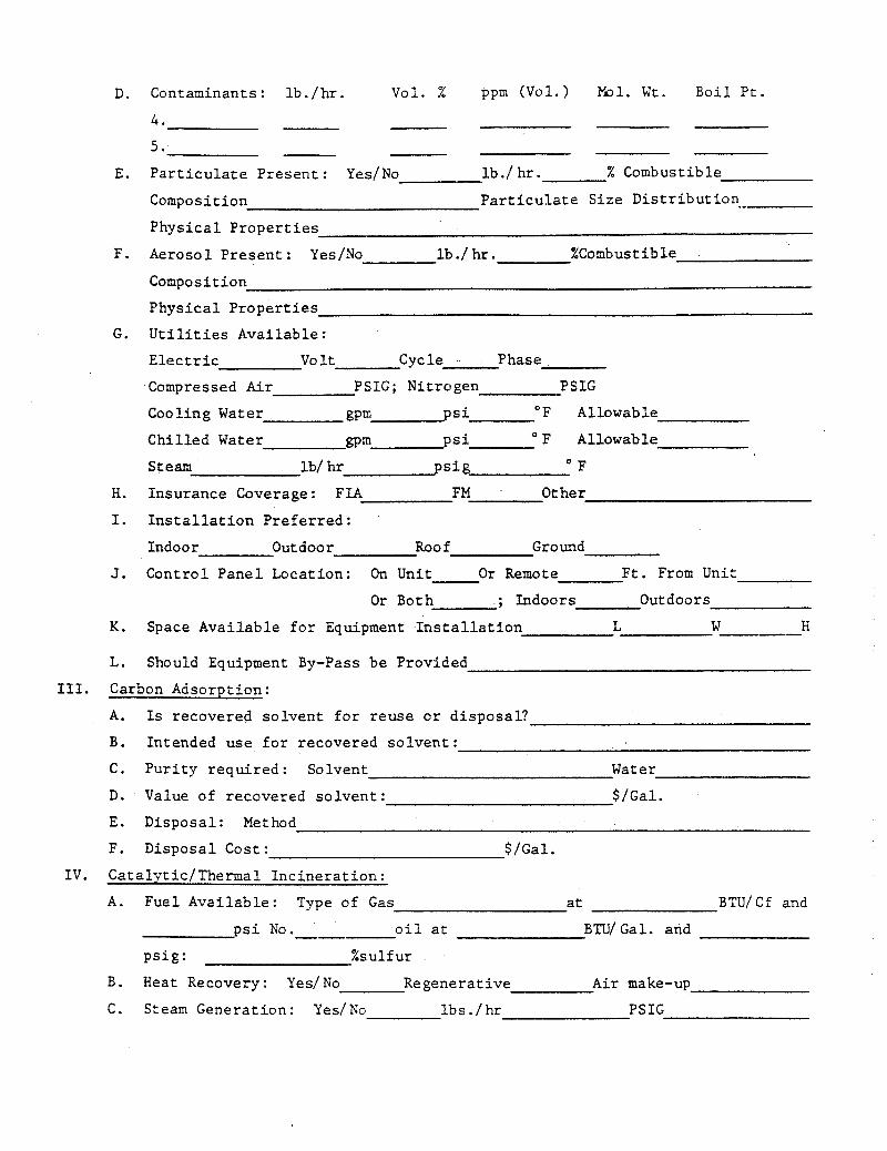
D. Contaminants: l b . / h r . V o l . % ppm (Vol . ) M o l . W t . B o i l P t .
4 .
5 . l b . / h r . % Combustible E. P a r t i c u l a t e Present : Yes/No
Composition P a r t i c u l a t e Size D i s t r i b u t i o n .-
Physic a 1 Proper t i e s
F. Aerosol Present : Yes/No l b ./ hr . %Combustible
Composition
Phys ica l P r o p e r t i e s
G. U t i l i t i e s Avai lable:
E l e c t r i c vo It Cycle . Phase
Compressed Air PSIG; Nitrogen PSIG
Coo l i n g Water gpm psi OF Allowable
Chi l l e d Water @m p s i OF Allowable
Steam lb/ h r p i g OF
H. Insurance Coverage: FIA FM Other
I. I n s t a l l a t i o n Prefer red :
Indoor Outdoor Roof Ground
J. Control Panel Location: On Unit O r Remote F t . From Unit
O r Both ; Indoors Outdoors
K. Space Avai lable f o r Equipment I n s t a l l a t i o n L W H --- L. Should Equipment By-Pass be Provided
111. Carbon Adsorption:
A. Is recovered so lvent f o r reuse o r d i sposa l?
B. Intended use f o r recovered so lvent :
C. P u r i t y requi red : Solvent Water
D. Value o f recovered so lvent : $/Gal.
E. Disposal: Method
F. Disposal Cost: $/Gal.
I V . Catalytic/Thermal Inc inera t ion :
A. Fuel Avai lable: Type of Gas a t BTU/ C f and
o i l a t B"U/ Gal. and --- p s i No.
p s ig : %sul fur
B. Heat Recovery: YeslNo R e genera t ive A i r make-up
C. Steam Generation: Yes/No l b s . / hr PSIG
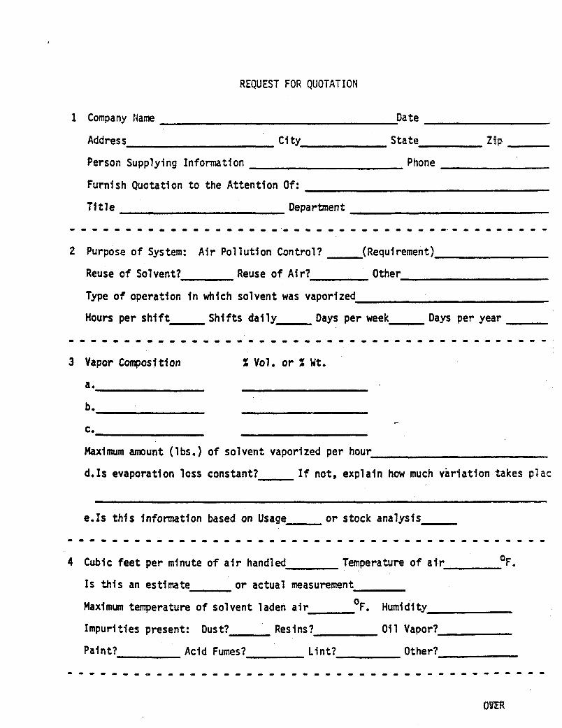
REQUEST FOR QUOTATION
1 Company Name Date
Address c i ty S ta te Z3p
Person Supplying Information Phone
Furnish Quotati on t o the Attention Of :
Tftle Oepartmen t
2 Purpose of System: Air Pollution Control? (Requirement)
Reuse o f Solvent? Reuse o f Air? Other
Type o f operation f n which solvent was vaporized
Hours per shift S h i f t s da i ly Days per week Days per year
3 Vapor Compost t ton X Vol. o r X W t .
a.
b,
C,
Maximum amount ( lbs.) of solvent vaporized per hour
d.1s evaporatton loss constant? If not, explain how much variation takes plac
eels this fnfonnatfon based on Usage - or stock analysts
4 Cubic feet per mfnute of a i r handled Temperature of a i r OF.
IS this an estimate o r actual measurement
Maxlmum temperature o f solvent laden a i r OF. Humidity
Impurities present: Dust? Resins? O i l Vapor?
Paint? Acid Fumes? L i n t ? Other?
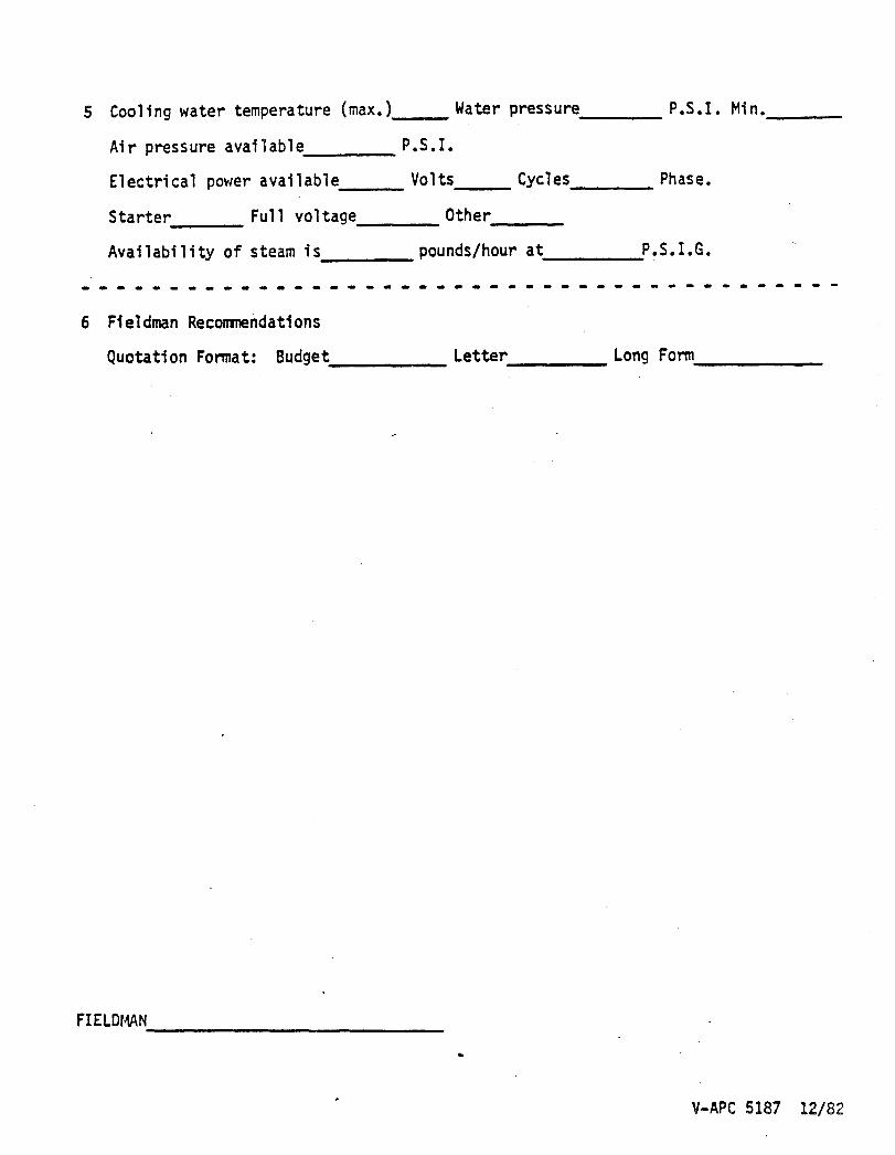
5 Cooling water temperature (max.) Water pressure P.S.I.
Ai r pressure avai 1 ab1 e P .S . I .
Electrical power available Volts Cycles Phase.
Starter Full voltage Other
Availability o f steam i s pounds/ hour a t P.S. I.G.
0 0 0 0 . 0 0 ~ 0 0 ~ . 0 . 0 0 . ~ 0 0 0 0 . 0 0 0 ~ . ~ 0 0 ~ 0 0 0 ~
6 Fieldman Recomndations
Min,
L I -
Quotation Format: Budget Letter Long F O ~
FI ELDMAN
V-APC 5187 12/82
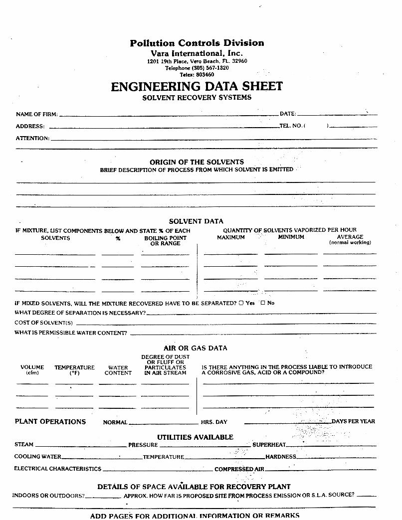
Pollution Controls Division Vara International, Inc.
1201 19th Place, Vero Beach, FL 32960 Telephone (305) 567-1320
Telex: 803460
ENGINEERING DATA SHEET SOLVENT RECOVERY SYSTEMS
NAME OF FIRM: DATE:
ADDRESS: TEL. NO. (
ATITNTION:
)
ORIGIN OF THE SOLVENTS BRIEF DESCRIPTION OF PROCESS FROM WHICH SOLVENT IS EMKTED
SOLVENT DATA IF M W R E . COMPONENTS BELOW AND STATE % OF EACH QUAN'XTXY OF SOLVENTS VAPORIZED PER HOUR
SOLVENTS A BOILING POINT MAXIMUM MINIMUM AVER AGE ORRANGE , (normal working)
IF MIXED SOLVENTS. W I U M E MIXTURE RECOVERED HAVE TO BE SEPARATED? 0 Yes
WHAT DEGREE OF SEPARATION IS NECESSARY?
COST O F SOLVENT(S)
WHATIS PERMISSIBLE WATER CONTENT?
No
AIR OR GAS DATA DEGREE OF DUST
OR FLUFF OR VOLUME TEMPERATURE WATER PARTICULATES IS THERE ANYTHING IN THE PROCESS L.IABLE TO INTRODUCE
(cfm) ( O F ) CONTENT W AIR STREAM A CORROSIVE GAS, ACID OR A COMPOUND?
PLANT OPERATIONS NORMAL
UTILITIES AVAILABLE S m M PRESSURE
COOLING WATER TEMPERATURE HARDNESS
ELECTRICAL CHARACTERISnCS COMPRESSED AIR
DETAILS OF SPACE AVkrLABLE FOR RECOVERY PLANT INDOORS OR OUTDOORS? APPROX. HOW FAR IS PROPOSED SITE FROM PROCESS EMISSION OR S.L.A. SOURCE? -
ADD PACIF.4 F O R Al3l3 lTlONAI I N F O R M A T I O N O R RFMARKC
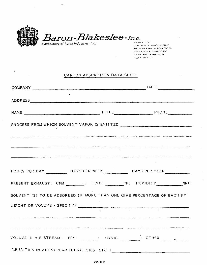
4
a subsidiary of Purex Indusfries, Inc. R E P L Y T O
2001 NORTH JANICE AVENUE MELROSE PARK, ILLINOIS 601 60 AREA CODE 3 12-450-3900 CABLE PRX-BARB-MLPK TELEX 25-4701
C A R B O N A D S O R P T I O N D A T A S H E E T
C 0 M P A N Y DATE
A D D R E S S
NALIE TITLE PHONE
P R O C E S S FROM W H I C H S O L V E N T VAPOR IS EMITTED /
HOURS PER D A Y D A Y S PER WEEK D A Y S PER YEAR
P R E S E N T E X H A U S T :
S O L V E N T . ( S ) T O B E
\‘!EIGHT OR VOLUME
C FA1 ; TEMP. OF; HUMIDITY %R H
A D S O R B E D
- S P E C I F Y )
( IF MORE T H A N O N E G I V E PERCENTAGE OF EACH B Y
VOLU:.IE I N A I R STREAiLl : PPhl : L B / t 1 R : OTt iER 0
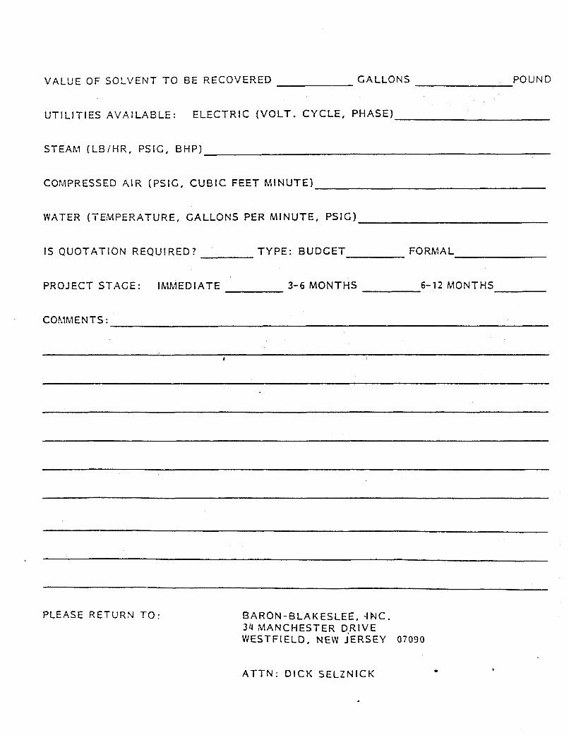
VALUE O F S O L V E N T T O BE R E C O V E R E D G A L L O N S POUND
U T I L I T I E S AVAILABLE: E L E C T R I C ( V O L T . C Y C L E , P H A S E )
STEAhl ( L B / H R , PSIC, B H P )
COhIPRESSED A I R (PSIG, CUBIC FEET h4INUTE)
WATER ( T E M P E R A T U R E , G A L L O N S PER M I N U T E , P S I G )
IS Q U O T A T I O N R E Q U I R E D ? TYPE: B U D G E T FORMAL
P R O J E C T S T A G E : IMMEDIATE 3-6 MONTHS 6-72 MONTHS
COMMENTS:
PLEASE RETURN T O : B A R O N - B L A K E S L E E , 4NC. 34 M A N C H E S T E R D-RIVE WESTFIELD, NEW JERSEY 07030
ATTN: DICK S E L Z N I C K .


![Untitled-1 [smhttp-ssl-42704.nexcesscdn.net] · Title: Untitled-1 Created Date: 20151119111453Z](https://img.pdfslide.net/doc/110x75/5f24e2450a7e2c6cc2663648/untitled-1-smhttp-ssl-42704-title-untitled-1-created-date-20151119111453z.jpg)


![Organic Memory Device Fabricated Through Solution …yylab.seas.ucla.edu/papers/0018-9219_93_1287_2005.pdforganic compounds [6], [7], exhibit interesting performance, they are far](https://img.pdfslide.net/doc/110x75/5ecb11b9d7384c0f6574766b/organic-memory-device-fabricated-through-solution-yylabseasuclaedupapers0018-92199312872005pdf.jpg)