Embed Size (px)
Citation preview

Recovery of Zn from municipal solid waste incineration bottom and fly ash by acid leaching and solvent extraction with the ligands CYANEX 272, CYANEX 921 and TBP Master of Science Thesis in the Master Degree Program; Innovative and
sustainable Chemical Engineering
KHURRAM SHAHZAD DEPARTMENT OF CHEMICAL AND BIOLOGICAL ENGINEERING INDUSTRIAL MATERIAL RECYCLING CHALMERS UNIVERSITY OF TECHNOLOGY Göteborg, Sweden, October 2011

Recovery of Zn from municipal solid waste incineration bottom and fly ash by acid leaching and solvent extraction with the ligands CYANEX 272, CYANEX 921 and TBP Khurram Shahzad © Khurram Shahzad October 2011. Examiner: Christian Ekberg Supervisor: Britt-Marie Steenari Department of Chemical and Biological Engineering CHALMERS UNIVERSITY OF TECHNOLOGY Göteborg, Sweden 2011

Abstract This work focuses on methods to recover zinc from Municipal Solid Waste (MSW) combustion ashes by acid leaching and solvent extraction. Leaching experiments were performed by pH stat titration for bottom and fly ash from a Swedish grate fired combustor firing sorted MSW. Nitric acid 0.6-3M was used for the ash leaching. The solvent extraction of Zn(II) from acid leachates was carried out using three extraction ligands that have been reported in the literature to be effective in separation of Zn from other metal ions in acid solutions. The ligands used were di- (2,4,4- tri methylpentyl) phosphinic acid (CYANEX 272), tri octyl phosphine oxide (CYANEX 921) and Tributyl phosphate (TBP) dissolved in kerosene and the extractions were carried out at initial pH 2, 3, 4 and 5. A special problem in these extractions is the separation between Zn(II) and Fe(III) from ash leachates. Leaching at pH 4 gives the lowest levels of iron in the leachate and may thus be a good starting point for the solvent extraction step since all tested ligands bind Fe(III) as well as Zn(II). CYANEX 272 gave the best results extracting about 90% of the Zn(II) in the ash leachates to the organic phase. For the fly ash leachate a ligand concentration of 30 vol% in kerosene was needed and for the bottom ash leachate the corresponding concentration was 20 vol%. The other two ligands gave significantly lower extraction results. Literature data indicate that their performance can be much better in a chloride rich media. Thus, they can be interesting to test if ash is leached with hydro chloric acid instead of nitric acid. Based on the results CYANEX 272 is indicated as a suitable extractant for the recovery of zinc from MSWI plant ashes.

Acknowledgements
First of all I would like to thank my supervisor Prof Britt Marie Steenari for providing me this opportunity and being helpful and supportive in my work.
I would like to express my gratitude for all the people that are connected to me and supported me directly or indirectly during the course of this thesis project.
I want to express my gratitude to my loving parents and my siblings; it is all due to prayers of my family, friends and relatives who continuously motivate me during this period of research work.
Khurram Shahzad

Contents Abstract ......................................................................................................................................................... 3
Acknowledgements ....................................................................................................................................... 4
Chapter: 1 Introduction ................................................................................................................................. 6
Chapter: 2 Aim of this work ......................................................................................................................... 7
Chapter: 3 Background ................................................................................................................................. 8
3.1 Combustion of waste ........................................................................................................................... 9
3.1.1 Fluidized bed incinerator .................................................................................................... 10
3.1.2 Mass burn incinerator/ Grate fire incinerator ...................................................................... 11
3.2 Ash from MSW incineration ............................................................................................................. 11
3.3 MSWI Ash Utilization ...................................................................................................................... 12
3.4 Leaching of Ash ................................................................................................................................ 13
3.4.1 Water as leaching agent ............................................................................................................. 13
3.4.2 Acid Leaching ............................................................................................................................ 13
3.4.3 L/S Ratio .................................................................................................................................... 13
3.5 Solvent extraction metal separation and recovery ............................................................................ 14
Chapter: 4 Material and methods ................................................................................................................ 18
4.1 Materials ........................................................................................................................................... 18
4.2 Analytical methods ........................................................................................................................... 18
4.2.1 Powder X-ray diffraction (XRD) ............................................................................................... 19
4.2.2 Inductive coupled plasma optical emission spectroscopy (ICP-OES) ....................................... 20
4.3 Solvent Extraction ............................................................................................................................. 21
4.5 Leaching Procedure .......................................................................................................................... 22
4.6 Solvent extraction experiment procedure ......................................................................................... 23
Chapter: 5 Results ....................................................................................................................................... 24
Chapter: 6 Discussion and Conclusions ...................................................................................................... 37
References ................................................................................................................................................... 39
Appendix ..................................................................................................................................................... 43

Chapter: 1 Introduction
Combustion of municipal solid waste (MSWI) is an important way of waste treatment, decreasing the volume of the waste by about 90% and giving a possibility to recover the thermal energy released as heat or electric power. However, the ashes formed, are in many cases a problem due to their contents of potentially leachable and toxic metals. A safe land-filling of the ash often requires some kind of stabilization treatment and specialized land-fill sites with recirculation of the leachate which is costly. Most countries have legal restrictions as to which types of wastes are allowed in the land-fills and this is also an obstacle for ash land-filling in some cases.
Recently, the possibilities to recover metals from MSWI ashes are being investigated. A quite advanced pilot stage process for recovery of Zn is being evaluated in Switzerland and hydro chemical methods for recovery of Cu have been investigated in laboratory experiments at the Chalmers University of Technology [2]. This Master thesis work is a part of a project on recovery of Zn from MSWI ashes presently being carried out at the same department.

Chapter: 2 Aim of this work
The aim of this thesis work was to determine the amount of Zn recovered from Municipal Solid Waste Incineration (MSWI) ashes in a process consisting of acid leaching and solvent extraction. The choice of suitable extraction ligands based on a literature review and an investigation of their efficiency in laboratory experiment was also included in the project. In addition, the possible co-extraction of Fe in the solvent extraction step was to be investigated.

Chapter: 3 Background
Waste is a heterogeneous material. There are different methods used for sorting the waste. Most of them are also commonly used in MSW: drum screens, Eddy current separator, induction sorting, near infrared sensors (NIR) and X-ray technology.
Currently two methods are used to handle sorted municipal solid waste: land filling and combustion (incineration). However, society is moving towards more sustainable material utilization and different procedures are being developed to recycle different metals. Experimental work has shown that ashes from waste incineration contain significant amounts of metals. Recovery of these metals from waste gives us opportunities to turn waste materials into valuable resources.
In many countries the amount of MSW generated per capita every year is quite high (Table 1). Most of the countries in the world have introduced rules and regulations regarding the handling of waste to minimize the impacts on the environment.
Table 1 Municipal waste generated and land filling (kg per capita) [1]
Countries Generated Land filled 1997 2002 2007 1997 2002 2007 EU-27 499 528 522 293 270 213 Euro area 536 568 553 260 235 181 BE 464 489 492 123 52 21 BG 577 500 468 433 404 388 CZ 318 279 294 318 205 243 DK 588 665 801 65 41 41 DE 658 640 564 216 137 3 EE 422 406 536 421 308 291 IE 547 698 788 439 504 467 EL 363 423 448 329 386 345 ES 561 645 588 319 359 350 FR 497 532 541 228 212 185 IT 468 524 550 374 331 286 CY 650 709 754 597 638 658 LV 254 338 377 238 280 322 LT 421 401 400 421 322 368 LU 607 656 694 145 129 130 HU 487 457 456 391 384 341 MT 437 543 652 352 501 606 NL 590 622 630 70 51 14 AT 532 609 597 189 187 86 PL 315 275 322 306 265 239 PT 405 439 472 269 319 297 RO 333 383 379 263 307 284 SI 589 407 441 491 357 342 SK 275 283 309 177 222 240 FI 448 459 507 281 286 267 SE 416 468 518 130 93 21 UK 533 600 572 461 465 324 TR 503 450 430 362 357 359

Countries Generated Land filled 1997 2002 2007 1997 2002 2007 IS 445 478 566 333 359 380 NO 619 677 824 383 274 262 CH 609 678 724 67 11 0
Municipal Solid Waste (MSW) is generated by different sources, households being one of the dominating sources. The definition of MSW differs from country to country. The Swedish definition includes hazardous waste and yard waste in addition to normal mixed waste from households. It also includes waste similar to MSW in its composition from offices, retail shops and schools. A comparison of MSW composition in some areas of the world is shown in Table 2, hazardous waste is not included.[2]
Table 2 Composition of MSW in % by weight. Hazardous waste is not included. [2]
Waste type EU-22 Sweden USA Philippines Organic waste including yard waste 7-52 45-55 23 45 Paper and wood 9-44 20-29 43 20 Plastic 2-15 9-11 11 23 Glass 2-12 1-3 6 1 Metal 2-8 2-4 8 4 Others 7-63 7-15 10 6
One way of reducing the volume of the waste is combustion. Combustion, or incineration as it is sometimes called in combination with combustion of waste, reduces the volume of waste by 80-90% and destroys pathogens and toxic organic compounds. However, a new waste is created, i.e. the ash.
3.1 Combustion of waste
The combustion of waste materials has to be carried out in a well controlled way and the pollutant emissions are kept low by use of specified temperature profiles to minimize the dioxin content of the flue gas, flue gas scrubbers, particle filters and ash treatment.
Combustion of MSW offers some advantages:
− Volume and weight reduction of waste. − Energy recovered from the organic waste. − MSW can be seen as a sustainable fuel source replacing fossil fuel for generation of heat
and power.
Combustion of MSW may also present some challenges:
− The flue gas contains particulate matter which has to be collected efficiently. − Toxic metals, such as mercury, lead, cadmium, arsenic, chromium, and nickel may leach
from the ash to the environment

− Corrosive and acidic gases such as hydrogen fluoride, hydrogen chloride, sulfur dioxide and nitrogen oxides are formed in the combustion and must be separated from the flue gas.
− The formation of incompletely burned compounds, like carbon monoxide, dioxins, furans and polycyclic aromatic hydrocarbons has to be avoided.
Contaminated waste water and ash has to be handled in a secure manner.
There are basically two processes to convert solid waste into useful energyelectricity.
1. Fluidized bed incinerator (FB).2. Mass burn incinerator (MB)/ Grate fire combustor
3.1.1 Fluidized bed incinerator
A fluidized bed incinerator consists of a sand bed contained in a chamber (Figure 1)continuous upward flow of primary combustion air to the fluidized bed to which the waste is fed via a weighing device. There are different types of fluidized bed furnaces which can be differing on the basis of their flow dynamics .i.e. bubblincirculating bed. Fluidized bed incinerators can be used for MSW, sewage sludge, liquid, gaseous and hazardous wastes. Fluidized bed combustion is normally carried out at relatively low temperature, i.e. at 850oC . It gives high combusNOx emissions, good heat transfer due to the sand bed and removal of SO2/SO3 can be accomplished by an addition of limestone(CaCO(CaMg(CO3)2). The heat is transferred to the walls which contain water tubes and in the fwhere heat exchangers are situated. Bottom ash is taken out from the bed to maintain the bed height and fly ash is collected by electrostatic precipitator and textile filters. A wet waste like sewage sludge can also be used in fluidized bed by adding another fuel with low moisture content [3]. Often, lime or limestone powder is added to the flue gas to absorb acid gases.
Corrosive and acidic gases such as hydrogen fluoride, hydrogen chloride, sulfur dioxide nitrogen oxides are formed in the combustion and must be separated from the flue
The formation of incompletely burned compounds, like carbon monoxide, dioxins, furans and polycyclic aromatic hydrocarbons has to be avoided.
d ash has to be handled in a secure manner.
There are basically two processes to convert solid waste into useful energy, such as heat and
Fluidized bed incinerator (FB). Mass burn incinerator (MB)/ Grate fire combustor
incinerator
luidized bed incinerator consists of a sand bed (Figure 1). There is a
continuous upward flow of primary combustion air to the fluidized bed to which the waste is fed via a weighing device. There are different types of fluidized bed furnaces which can be differing on the basis of their flow dynamics .i.e. bubbling, turbulent, or circulating bed. Fluidized bed incinerators can be used for MSW, sewage sludge, liquid, gaseous and hazardous wastes. Fluidized bed combustion is normally carried out at relatively low temperature, i.e.
C . It gives high combustion efficiency, low emissions, good heat transfer due to the sand bed
can be accomplished by an CaCO3) or dolomite
). The heat is transferred to the walls which contain water tubes and in the flue gas channel where heat exchangers are situated. Bottom ash is taken out from the bed to maintain the bed height and fly ash is collected by electrostatic precipitator and textile filters. A wet waste like sewage sludge can also
d by adding another fuel with low moisture content [3]. Often, lime or limestone powder is added to the flue gas to absorb acid
Figure 1: Fluidized bed incinerator
Corrosive and acidic gases such as hydrogen fluoride, hydrogen chloride, sulfur dioxide nitrogen oxides are formed in the combustion and must be separated from the flue
The formation of incompletely burned compounds, like carbon monoxide, dioxins, furans
such as heat and
moisture content [3]. Often, lime or limestone powder is added to the flue gas to absorb acid
: Fluidized bed incinerator

3.1.2 Mass burn incinerator/ Grate fire
incinerator
In this incinerator the waste is fed on a conveyor belt or on a grate and air is blown from underneath the grate and the combustion is carried out at high temperature heat produced is transferred to the water tubes in the walls by radiation. Additional heat transfer is achieved from the flue gas to heat exchangers in the flue gas channel. The bottom ash is often in melted form due to high temperature ~1100and collected in water bath below the grate where it is cooled down. Fly ash is collected by electrostatic precipitators and textile filters along with some extra devices for better cleaning of flue gas. [3] Limestone powder or hydrated lime is introduced in flue gas line before filters to absorb HCl and SOx. For the absorption of mercury and dioxins/furans activated carbon is used. Flue gas treatment is performed in both FBC and mass burn incinerators.
3.2 Ash from MSW incineration
Basically two types of ashes are produced in the MSW incineration plant, fly ash and bottom ash. The particles which are really small in size are carried by the flue gases and collected by cleaner devices present before the exhaust to air; particles collected in these cleaner fly ash. The particles which are larger in size called bottom ash. This ash flow contains ceramic materials, broken glass and stonesMSWI ash [2]
Elements
Al Ca Fe K Mg Na Si Cl S As Ba Cd Cr
Mass burn incinerator/ Grate fire
In this incinerator the waste is fed on a conveyor belt or on a grate and air is blown from underneath the grate and the combustion is
(Figure 2). The heat produced is transferred to the water tubes in
by radiation. Additional heat transfer is achieved from the flue gas to heat exchangers in the flue gas channel. The bottom ash is often in melted form due to high temperature ~1100o C and collected in water bath below the grate where it is cooled down. Fly ash is collected by electrostatic precipitators and textile filters along with some extra devices for better cleaning of flue gas. [3] Limestone powder or hydrated lime
d in flue gas line before filters to absorb HCl and SOx. For the absorption of mercury and dioxins/furans activated carbon is used. Flue gas treatment is performed in both FBC
3.2 Ash from MSW incineration
f ashes are produced in the MSW incineration plant, fly ash and bottom ash. The particles which are really small in size are carried by the flue gases and collected by cleaner devices present before the exhaust to air; particles collected in these cleaner devices are called fly ash. The particles which are larger in size are collected in the bottom of the combustor and
This ash flow contains the minerals with high melting points, metals parts, ceramic materials, broken glass and stones. Table 3 gives typical element concentrations in
Elements Bottom ash (mg/kg Ash)
Fly ash (mg/kg Ash)
22000-73000 49000-90000 370-123000 74000-130000 4100-150000 12000-44000 750-16000 22000-62000 400-26000 11000-19000 2800-42000 15000-57000 91000-308000 95000-210000 800-4200 29000-210000 1000-5000 11000-45000 0.1-190 37-320 400-3000 330-3100 0.3-70 50-450 23-3200 140-1100
Figure 2: Mass burn incinerator/ Grate fire
f ashes are produced in the MSW incineration plant, fly ash and bottom ash. The particles which are really small in size are carried by the flue gases and collected by cleaner
devices are called collected in the bottom of the combustor and
the minerals with high melting points, metals parts, able 3 gives typical element concentrations in
: Mass burn incinerator/ Grate fire incinerator

Table 3 Typical element concentrations in MSWI ash.
There is quite a large amount of toxic metals present in bottom ash (Cr, Cu and Ni) as well as in the fly ash (Hg, Pb and Zn) are shown in table 3. The data shows that the composition of MSW ash varies significantly. [2, 10]
Many physical and chemical reactions occur in the combustion unit and result in partitioning of metals between fly and bottom ashes. Research work is made in order to understand the reasons for the partitioning of metals in bottom and fly ash in the combustion process. As an example, it has been shown that chloride forming elements e.g. As, Cd, Hg, Pb, Sb and Zn are mainly present in fly ash, whereas oxide forming elements e.g. Cr, Cu and Ni are present in bottom ash [10]. Temperature and gas composition both affect the volatilization of metal compounds. Thermodynamic equilibrium calculations and measurements show that the volatility of metals (Cd, Pb, Cu and Zn) increases due to high chlorine compounds concentration e.g. HCl and due to reducing atmosphere, while on the other side the presence of sulphur decreases the volatility of metals. In fly ash these metals elements are condensed on small particles surfaces and gaseous metals are also condensed when flue gas stream is cooled. [2]
It is important to know if metal compounds are concentrated in the centre parts of ash particles or if they are mainly found on the surfaces of the particles. Synchrotron based X-ray fluorescence spectroscopy and other analytical techniques have been used for investigations of the distribution of metals in and on fly ash particles. Camerani et al. [45] found that the concentrations of Cd and Pb were highest inside the fly ash particles which then were covered with different impurities. However, Zn was found both in the inner parts and on the outer surface of ash particles. E. Fujimori [46] and his co workers investigated that acid soluble metals i.e. Cd, Cu, Mo, and Zn are enriched on the surface of fly ash particles, while Co, Mn, Ni and Pb are present both in the inner parts and on the outer surface of ash particles. The spatial distribution is important for the leachability of the metals. Metal compounds inside a particle can be enclosed by a matrix with low solubility and therefore get a low leachability, whereas metal salts adsorbed on the particle surface are easily accessed by the leachate. [46]
3.3 MSWI Ash Utilization
Fly ashes from MSW incineration often have a high content of potentially toxic metals and solid chlorides as compared to the bottom ash. However, the possible harmful effects can be decreased by stabilization and solidification.
Cu 190-8200 600-3200 Hg 0.02-8 0.7-30 Mn 80-2400 800-1900 Mo 2-280 15-150 Ni 7-4200 60-260 Pb 100-13700 5300-26000 Sb 10-430 260-1100 V 20-120 29-150 Zn 610-7800 9000-70000

MSWI ashes can be used as construction material, such as in making top covers for landfill areas which can protect environment form dangerous gas emissions and also stop water infiltration into the waste. It is a cheaper filler material than for example crushed rock. [4, 5, 6]
One company in Switzerland extracts Zn metal from ashes on a large scale. [2, 7] The treated ash is used in covering landfills.
3.4 Leaching of Ash
3.4.1 Water as leaching agent
Generally, the water soluble fractions of metals in ash are low. However, variation in some parameters, such as contact time, L/S ratio and pH affects the leaching of ash with water. Experiments performed by Karlfeldt et al [2] showed that if the leaching time increased the concentration of Zn2+ in the leachate decreased. The reason was probably precipitation of secondary compounds, such as Zn(OH)2.
3.4.2 Acid Leaching
Generally acidic pH increases the release of major and minor metals from MSWI ash during leaching as compared to leaching in water. Some common acids used for this purpose are HCl, HNO3 and H2SO4. The concentrations of different metals are controlled by the solubility equilibrium of the compounds that the metals occur in. At low pH, i.e. below 3 there is high release of Cu, Mn, Zn, Al, Fe and Si but as the pH is increased the major metals Al, Fe and Si are usually less soluble.
The ability to react as an acid or a base is known as amphoterism and also known as amphoteric behavior. Some hydroxides behave both as bases and acids under different conditions such as Al, Pb and Zn.
The zinc hydroxide Zn (OH)2 act as base and as acid as shown in Figure 3 below.
Figure 3 The amphoteric behavior of Zn(OH)2
3.4.3 L/S Ratio
The L/S ratio gives the weight ratio of liquid and solids used in a leaching experiment. If the leaching of a specific metal is controlled by the chemical solubility of the compounds of that metal a higher amount of metal is leached as the L/S ratio is increased. However, it has often been observed that metal ions and anions present in the ash sample form secondary compounds, and the precipitation of these secondary compounds decreases the leaching of the metal. Different experimental work that was performed by Guyonnet and co-workers verify the effect of L/S ratio on release of reactive and non-reactive constituents. The results show that non-reactive constituents such as Ca, K and Na are released quickly, but they are dependent on L/S

ratio, while the release of reactive constituents such as Cr and Al is more dependent on kinetics of reaction than on the L/S ratio. [34]
3.5 Solvent extraction metal separation and recovery
There are different types of steel used nowadays and to protect that steel from corrosion is very important. Thus metallic coating techniques was introduced to improve the corrosion resistance of steel. Approximately 50% of a car chassis is coated. The coating method is called hot-dip galvanizing and in this method zinc is used for coating metal sheets. HCl spent pickling solution contain zinc and iron. [40] Solvent extraction methods for separation of Zn(II) over Fe(II) by solvent extraction from hot-dip galvanizing industry effluent have been developed. The ligands suggested as suitable in these methods are Cyanex 272, Cyanex 302, Cyanex 921, Cyanex 923, ALAMINE 336 and TBP. A common problem is that oxidation of Fe (II) to Fe (III) can occur during solvent extraction. Thus, if Fe (III) is present in the spent pickling solution, it must be reduced to iron(II) before extraction. [41, 40]
The recovery of Cu(II), Ni(II) and 95% Zn(II) at pH 3 from aqueous sulfate–acetate solution has been carried out using solid phase sol–gel silica containing immobilized Cyanex 272. [42]. N-alkyl- and N,N-dialkylpyridine-2(and-3)-carbox amides can be used to extract Zn(II) from chloride medium. Results shows that 80% of extraction done at 1M chloride concentration [43]. Weng Fu and his co-workers perform solvent extraction experiments to extract zinc from ammonical/ammonium chloride solutions by a sterically hindered β-diketone and its mixture with tri-n-octylphosphine oxide. Their results gave D-values [chapter 4] in the range 0.16-0.33. [44]
The basic concept of solvent extraction is the use of a ligand forming a complex with the target metal ion. A ligand is an ion or molecule which exists independently of any complex that it might form. In the complex [Co (NH3)6]
3+, the ammonia molecules, which can exist outside of the complex, are acting as ligands. The complex is a combination of a Lewis acid (the central metal atom/ion) and some Lewis bases (the ligands).
The main way of classifying ligands is by the number of points at which they are attached to, or bound to, the metal center.
Monodentate: Ammine NH3, Aqua H2O, Hydroxo OH-, Chloro Cl-,
Bidentate: Acetylacetonato (CH3COCHCOCH3) - binding via oxygen,
Bipyridene ethylene diamine (H2NCH2CH2NH2), Oxalato (C2O42-)
Tridentate: Diethylenetriamine (NH (CH2CH2NH2)2) (binding via nitrogen)
Polydentate: EDTA(Ethylene-di-amine tetra acetic acid), (binding via nitrogen and oxygen), Triaminoethylamine ( N(CH2CH2NH2)3) (Tetradentate, binding via nitrogen)
In this thesis work two phosphinic acid extractant (ligands) are used to extract zinc i.e. Cyanex 272 (BTMPPA which is short for Bis (2, 4, 4-trimethylpentyl phosphinic acid), Cyanex 921(Trioctyl phosphine oxides) and TBP (Tributyl phosphate).

Some properties of these ligands are discussed below;
1. Di- (2,4,4- tri methylpentyl) Phosphinic acid (Cyanex 272)
Cyanex 272 is di-alkyl phosphinic acid produced by Cytec and Sigma-Aldrich which can be used for the extraction of metal ions. Researchers use Cyanex 272 (Bis (2,4,4-trimethylpentyl) phosphinic acid), CYANEX 302 (bis(2,4,4-trimethylpentyl)monothiophosphinic acid), DEHPA (Di-(2-ethylhexyl)phosphoric acid), to extract zinc and chromium (III) from alloy electroplating waste water and results show that Zn(II) was extracted by all ligands, but that DEHPA also is effective in extraction of Cr(III) [36]. The results of Rickelton and Boyle show that Cyanex 272 extract Zn(II) at pH 3 from sulphate solutions containing Ca. [37] G. Wang, L.G. Wang, D.Q. Li, investigated the synergistic extraction of Zn(II) with a mixture of sec-nonylphenoxy acetic acid CA-100 and Cyanex 272 and found that this synergistic system increased the Zn(II) extraction as compared to the extraction of Cd(II) [38]. Q. Jia, D. Li, C. Niu, also observed a synergistic effect when extraction of Zn(II) from chloride medium by mixture of a primary amine and Cyanex 272 was done.[39]
In this thesis work, two concentrations (30vol% Cyanex 272 = 0.807 M ; 20vol% Cyanex 272 = 0.538 M ) were prepared in kerosene to investigate Zn(II) extraction. Chemically the extraction equation can be represented as suggested in reference [20] (bars represent organic phases).
Zn2+ +1.5(HA)2 ⇔ ZnA2(HA) + 2H+
The binding of Cyanex 272 ligands to Zn2+ ions is shown in Figure 4.
Figure 4 Binding of Cyanex 272 ligands to Zn2+ ions
Zinc was found as Zn(OH)+ in very dilute acidic solution[19]. In that case Cyanex 272 makes a dimer in kerosene for extraction of zinc. The extraction equation is shown below. The Cyanex 272 dimer is represented by (HA)2 and bars represent organic phases. [19]
Zn(OH)+ +2(HA)2 ⇔ Zn(OH)A.(HA)3 + H+
2. Tri Butyl phosphate (TBP)
Tri Butyl phosphate is commercially produced by Sigma-Aldrich and it is used in metal extraction processes. S.I. El Dessouky, Y.A. El-Nadi, I.M. Ahmed, E.A. Saad b, J.A. Daoud, used TBP along with other ligands (Cyanex 921, Cyanex 923, Cyanex 302, Alamine 336 and (TOPO) Tri octylphosphine oxide to recover Zinc from HCl spent pickling solutions by solvent extraction and results shows that efficient recovery of 55% zinc is done by TBP [40]. At 0.1M acid in the water phase complex type species appear in the organic phase (HZnCl3, HZnCl4 and HZnCl3. 2TBP) and at 2.7M acid the formation of a complex specie H2ZnCl4·2TBP has been observed. In a water phase at lower acidity ZnCl2 is the dominant species and at higher acidity
*R= C8H17: dotted line show weak covalent bonds.

ZnCl3- and ZnCl4
2- are more dominant. [21] The extraction equation describing extraction at high acidity is shown below and the structure of the ligand zinc-ion complex is shown in Figure 5.
H+ + ZnCl-3 + 3TBP ⇔ HZnCl3 .3TBP
Figure 5 The HZnCl3 .3TBP complex
Investigations has shown that the presence of Fe(III) during extraction of Zn(II) causes more transfer of acid and water to TBP. However kerosene presence decreases the hydrophilic character of TBP and as a result the transfer of water to organic phase decreases. [21, 22]
3. Tri-octylphosphine Oxide (Cyanex 921(C921)) +( 5% Octanol)
Tri-octylphosphine oxide commercially knows as Cyanex 921 is produced by Cytec and Sigma-Aldrich and it can be used as a ligand to extract metal species. Octanol is used as phase modifier to increase the solubility of the ligand in kerosene. S.I. El Dessouky, Y.A. El-Nadi, I.M. Ahmed, E.A. Saad b, J.A. Daoud, investigated the effect of hydrochloric acid concentrations in the range 0.5-7M using Cyanex 921 and octanol in kerosene. At equilibrium the extracted species was HZnCl3 .2C921 as described in Figure 6 and the extraction equation below. [21]
H+ + ZnCl-3 + 2C921 ⇔ HZnCl3 .2C921
Figure 6 The HZnCl3 .2Cyanex921 complexes
*R= Butyl: dotted line show weak covalent bonds and bars represent organic phases.
*R= C8H17: bars represent organic phases

Experimental results verify that Cyanex 921 work well in HCl medium in the range of (3.5 to 5M). [21] If the concentration of chloride [Cl-] ions increased from 3.5M to 5M and [H+] ions remain constant at 3M there is no effect on Zn(II) extraction (73%), while the extraction of Fe(III) increased from 37% to 47%.

Chapter: 4 Material and methods
4.1 Materials
The ash samples of bottom and fly ash from a mass burn incinerator/ grate fire incinerator (MBF) burning 100% MSW. Dry lime was added to the flue gas channel before the filter. The municipal solid waste incineration plant (MSWI) Gärstadsverken producing the ash samples is situated in Linköping. The element concentrations determined at the Eurofins Lab are shown below in Table 4.
Table 4 Concentrations of main and minor elements in the original ash samples
Main
Element
Bottom ash Fly ash Minor
Element
Bottom
ash
Fly ash
mg/kg dry
ash
mg/kg
dry ash
mg/kg
dry ash
mg/kg
dry ash
Si 183300 67300 As 68 240
Al 37700 36100 Ba 1300 140
Ca 92700 180700 Cd 4.3 83
Fe 70300 20100 Co 33 34
K 11200 21100 Cr 490 450
Mg 12200 18100 Cu 2700 840
Na 37700 26100 Hg <0.046 <0.045
P 2900 5000 Mn 1000 1100
Ti 12200 14100 Mo <20 22
Ni 240 220
Pb 1400 3000
Sn 310 380
V 60 70
Zn 3800 17100
4.2 Analytical methods
For identification of crystalline components in the ashes, X-ray powder diffraction (XRD) was used. In addition, determination of the oxidation states of iron in some samples was carried out by synchrotron based X-ray absorption spectroscopy (XAS) in a parallel project. The concentrations of dissolved metal ions in leachate solutions were determined using inductive coupled plasma mass spectroscopy (ICP-MS) and inductive coupled plasma optical emission spectroscopy (ICP-OES). [2]
The techniques are described shortly below.
1. Powder X-ray diffraction (XRD) 2. Inductive coupled plasma optical emission spectroscopy (ICP-OES)
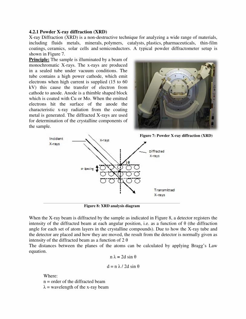
4.2.1 Powder X-ray diffraction (XRD)
X-ray Diffraction (XRD) is a nonincluding fluids metals, mineralscoatings, ceramics, solar cells andshown in Figure 7. Principle: The sample is illuminated by a beam of monochromatic X-rays. The x-rays are produced in a sealed tube under vacuum conditions. The tube contains a high power cathode, which emit electrons when high current is supplied (15 to 60 kV) this cause the transfer of electron from cathode to anode. Anode is a thimble shapedwhich is coated with Cu or Mo. When the emitted electrons hit the surface of the anode the characteristic x-ray radiation from the coating metal is generated. The diffracted Xfor determination of the crystalline components of the sample.
When the X-ray beam is diffracted by the sampleintensity of the diffracted beam at each angular position, i.e. as a function of angle for each set of atom layers in the crystalline compounds). Due to how the Xthe detector are placed and how thintensity of the diffracted beam as a function of 2 The distances between the planes of the atoms can be calculated by applying Bragg’s Law equation.
Where: n = order of the diffracted beam
λ = wavelength of the x-ray beam
Figure
ray diffraction (XRD)
non-destructive technique for analyzing a wide range of materials, minerals, polymers, catalysts, plastics, pharmaceuticals
, solar cells and semiconductors. A typical powder diffractometer
The sample is illuminated by a beam of rays are produced
in a sealed tube under vacuum conditions. The tube contains a high power cathode, which emit electrons when high current is supplied (15 to 60 kV) this cause the transfer of electron from cathode to anode. Anode is a thimble shaped block which is coated with Cu or Mo. When the emitted electrons hit the surface of the anode the
ray radiation from the coating metal is generated. The diffracted X-rays are used for determination of the crystalline components of
ray beam is diffracted by the sample as indicated in Figure 8, a detector registers the intensity of the diffracted beam at each angular position, i.e. as a function of θangle for each set of atom layers in the crystalline compounds). Due to how the Xthe detector are placed and how they are moved, the result from the detector is normally given as ntensity of the diffracted beam as a function of 2 θ
The distances between the planes of the atoms can be calculated by applying Bragg’s Law
n λ = 2d sin θ
d = n λ / 2d sin θ
n = order of the diffracted beam ray beam
Figure 7: Powder X-ray diffraction (XRD)
Figure 8: XRD analysis diagram
destructive technique for analyzing a wide range of materials, pharmaceuticals, thin-film
A typical powder diffractometer setup is
, a detector registers the intensity of the diffracted beam at each angular position, i.e. as a function of θ (the diffraction angle for each set of atom layers in the crystalline compounds). Due to how the X-ray tube and
ey are moved, the result from the detector is normally given as
The distances between the planes of the atoms can be calculated by applying Bragg’s Law
ray diffraction (XRD)

d = distance between the atom planes θ = angle of incidence for the x
The distance between the atom planes (dLaw equation. The d-spacings recorded are characteristic for the crystalline compounds present in the sample and this makes X-a sample. [17, 27, 28]
Joint Committee on Powder Diffraction Standards (JCfor Diffraction Data (ICDD) collect powder diffraction data from different organic, inorganic and organ metallic compounds and compile them in a database containing over 50000 patterns. [29] This database is used in the identification of compounds in analyzed samples.
The main applications of powder X
− To identify crystalline phases and orientation − To measure thickness of thin films and multi− To determine atomic arrangement− To determine structural properties: Lattice parameters (10
composition, preferred orientation (Laue) orderexpansion.
4.2.2 Inductive coupled plasma optical emission spectroscopy (ICP
Concentrations of trace metals in liquid sample can be determined by using ICPtechnique. Figure 9 shows typical
Principle: A nebulizer is supplied with liquid samples through a capillary tube. a mixture of fine droplets. In the next step the mixture is compressed and released into a spray chamber containing a plasma torch. With the help of the plasma torch thatoms increases and electrons of an atom can enter in exited states. When these electrons return from a higher energy state to a lower energy state a photon is emitted. The intensity of these emissionsin the optical emission detector. element present in the liquid sample has unique wavelengths and ICP-OES measurethe intensity of each wavelength. Standard solutions of known concentrations are made for calibration of results for quantitative measurements. All ICPanalysis in this thesis work was carried out on an iCAP 6000 series ICP Optical Emission Spectrometer.
d = distance between the atom planes = angle of incidence for the x-ray beam
The distance between the atom planes (d- spacing) can be determined by rearranging spacings recorded are characteristic for the crystalline compounds present
-ray powder diffraction useful in determining the composition of
Joint Committee on Powder Diffraction Standards (JCPDS) known as The International Centre collect powder diffraction data from different organic, inorganic
and organ metallic compounds and compile them in a database containing over 50000 patterns. he identification of compounds in analyzed samples.
ain applications of powder X-ray diffraction are:
To identify crystalline phases and orientation To measure thickness of thin films and multi-layers To determine atomic arrangement
uctural properties: Lattice parameters (10-4Å), strain, grain size, phase composition, preferred orientation (Laue) order-disorder transformation and thermal
4.2.2 Inductive coupled plasma optical emission spectroscopy (ICP-OES)
f trace metals in liquid sample can be determined by using ICPtypical ICO-OES equipment.
A nebulizer is supplied with liquid samples through a capillary tube. a mixture of fine droplets. In the next step the mixture is compressed and released into a spray chamber containing a plasma torch. With the help of the plasma torch the thermal energy of the atoms increases and electrons of an atom can enter in exited states. When these electrons return from a higher energy state to a lower energy state a photon is emitted.
ese emissions measured the optical emission detector. Every
element present in the liquid sample has OES measures
the intensity of each wavelength. Standard solutions of known concentrations are made for calibration of results for
ements. All ICP-OES analysis in this thesis work was carried out on an iCAP 6000 series ICP Optical
Figure 9: Inductive coupled plasma optical emission
spectroscopy (ICP-OES)
pacing) can be determined by rearranging Bragg’s spacings recorded are characteristic for the crystalline compounds present
ray powder diffraction useful in determining the composition of
The International Centre collect powder diffraction data from different organic, inorganic
and organ metallic compounds and compile them in a database containing over 50000 patterns. he identification of compounds in analyzed samples.
4Å), strain, grain size, phase disorder transformation and thermal
f trace metals in liquid sample can be determined by using ICP-OES analytical
A nebulizer is supplied with liquid samples through a capillary tube. Argon gas form a mixture of fine droplets. In the next step the mixture is compressed and released into a spray
e thermal energy of the
: Inductive coupled plasma optical emission

4.3 Solvent Extraction
Solvent or liquid- liquid extraction is a separation process where the distribution of species (A) between two immiscible liquid phases (water [A]aq and organic [A]org) is utilized. The desired metal species present in the water phase is transferred to the organic phase by using metal specific extractants (ligands).At the laboratory scale the extraction is carried out in a separation funnel or extraction funnel, where two liquids are mixed thoroughly. When the distribution of species reaches its equilibrium the concentration of metal ions in water and organic phases are denoted [A]aq, [A] org. [14]
The distribution ratio is defined according to IUPAC as;
‘‘The total analytical concentration of the substance in the organic phase to its total analytical
concentration in the aqueous phase ’’
� =[�]���
[�]
[15]
Some companies are manufacturing equipments for solvent extraction on an industrial scale such as, e.g mixer-settlers as offered by MEAB Metallextraktion AB in Göteborg. [12]A typical mixer
settler unit is shown in Figure 10.
A. Mixing chamber B. Variable speed stirrer motor C. Turbine pump impeller D. Inlet, heavier solvent E. Inlet, lighter solvent F. Settling compartment G. Outlet/inlet mixer/settler H. Picket fence distributor I. Outlet weir, lighter solvent J. Underflow, heavier solvent K. Outflow
cavity, heavier solvent L. Adjustable jack-leg outflows, easier solvent M. Phase boundary [13]
The suggested recovery method for Zn from ash is shown in Figure 11.
Figure 10: Mixer settler units

4.5 Leaching Procedure
In the leaching experiments carried out in this work, the ash samples (bottom ash and fly ash from Gärstadsverken in Linköping) were leached at a constant pH in a pHautomatic titration unit (Metrohm Titrino) . The ash sample was mixed with ultra pu(milli-Q water), nitric acid was added to reach a pH close to the chosen pH and the sample was stirred for 48 hours while the pH was kept constant by small additions of acid. The resulting L/S was calculated based on all liquid added. The L/S values were kept reasonably similar in all experiments (7-leaching period the solution was filtered or centrifuged to separate solid particles. This whole process is called pH-static experiment.
Experiments were carried out at pH 2, 3, 4 and 5. The leached amount of metals was measured by ICP-OES and a filtered solid particle (leached ash) was observed using Xdiffraction to determine which crystalline compounds they contained.
Presence of Nitrate in the solution form complex compounds with metals, but solubility of several ash matrix compounds also depend on pH.
Table 5 Molarity of the nitric acid (HNO
Samples
5432
Ash amount: 60grams
Volume of liquid (mil-Q): 300ml
Time for leaching: 48hours
In the leaching experiments carried out in this work, the ash samples (bottom ash and fly ash from Gärstadsverken in Linköping) were leached at a constant pH in a pH-static automatic titration unit (Metrohm Titrino) . The ash sample was mixed with ultra pure water
Q water), nitric acid was added to reach a pH close to the chosen pH and the sample was stirred for 48 hours while the pH was kept constant by small additions of acid. The resulting L/S was calculated based on all liquid
es were kept reasonably -9). After the
leaching period the solution was filtered or centrifuged to separate solid particles. This
static experiment.
carried out at pH 2, 3, 4 and 5. The leached amount of metals was measured
OES and a filtered solid particle (leached ash) was observed using X-ray powder diffraction to determine which crystalline
the solution form complex compounds with metals, but solubility of several ash matrix compounds also depend on pH.
olarity of the nitric acid (HNO3) for each pH-static experiment:
Samples
at pH
Molarity
Fly ash Bottom
ash
5 0,6 0,6 4 0,8 0,8 3 1,4 1,4 2 3,0 3,0
300ml
Figure 11: Process Flow Chart
the solution form complex compounds with metals, but solubility of
static experiment:
: Process Flow Chart

Table 6 L/S ratio at different pH of the leachate solution
pH L/S Fly ash L/S Bottom ash
5 9 6.8 4 10 6.6 3 9.7 7.4 2 7.9 6.9
4.6 Solvent extraction experiment procedure
A separation funnel of 50ml was used to separate two phases. Poured 5ml of each organic and water phase in funnel and shake continuously for 5 min. The funnel valve was opened a couple of times to release the pressure that has built up. After shaking the sample was left for phase separation for at least 5min or till full phase separation had occurred. The samples of water and organic phase were saved in separate sample flasks. Samples were prepared for ICP-OES experimental analysis. The organic phase is stripped with strong H2SO4 acid to separate Zn from Fe. (This step was not done due to lack of time)

Chapter: 5 Results
Table 5 shows the extraction times used in the experiments, the times needed for full phase separation, the ratios between volume of organic phase/volume of aqueous phase and the final pH in the aqueous phase at the end of extraction. After extraction with TBP for bottom ash leached at pH 2 three phases occurred in the extraction funnel which are named phase A, B and C. A is the organic phase at the top, B was located in the middle and C is the bottom aqueous phase. Phase B formed a gel. In the extraction of the fly ash pH 3 leachate with Cyanex 921 a gel was formed at the bottom of the extraction funnel.
The pH decreases during extraction and formation of metal-ligand complexes due to the release of H+ ions are shown in Tables 7 and 8.
Table 7 Parameters of the solvent extraction experiments for separation of Zn2+ from bottom ash leachates
Samples Extraction
time, min
Separation
time, min
Org/
Aqua
Vol ratio
Water phase
pH (after
extraction)
Cyanex 272 30%
Extraction at pH 5 5 10 1:1 3.0
Extraction at pH 4 5
10
1:1
2.2
Extraction at pH 3 5
10
1:1
1.6
Extraction at pH 2 5
1440
1:1
1.5
Cyanex 272 20%
Extraction at pH 5 5
10
1:1
3.0
Extraction at pH 4 5
10
1:1
2.1
Extraction at pH 3 5
10
1:1
1.6
Extraction at pH 2 5
1200
1:1
1.6
5% Octanol and Cyanex 921
Extraction at pH 5 5
5
1:1
3.2
Extraction at pH 4 5
60
1:1
2.5
Extraction at pH 3 5
1080
1:1
2.3
Extraction at pH 2 5
120
1:1
2.3
TBP
Extraction at pH 5 5
10 1:1
4.7
Extraction at pH 4 5
5
1:1
3.3
Extraction at pH 3 5
5
1:1
2.6
Extraction at pH 2 5
960
1:1
Gel

Table 8 Parameters of the solvent extraction experiments for separation of Zn2+ from fly ash leachates
Samples Extraction
time, min
Separatio
n time,
min
Org/
Aqua
Vol ratio
Water phase
pH (After
Extraction)
Cyanex 272 30%
Extraction at pH 5 5 10 1:1
2
Extraction at pH 4 5
10
1:1
1.7
Extraction at pH 3 5
1200
1:1
1.6
Extraction at pH 2 5
1440
1:1
1.3
Cyanex 272 20%
Extraction at pH 5
5
10
1:1
2
Extraction at pH 4 5
10
1:1
1.7
Extraction at pH 3 5
60
1:1
1.7
Extraction at pH 2 5
1200
1:1
1.3
5% Octanol and Cyanex 921
Extraction at pH 5 5
5
1:1
2.8
Extraction at pH 4 5
5
1:1
2.4
Extraction at pH 3 5
1080
1:1
GEL
Extraction at pH 2 5
120
1:1
1.9
TBP
Extraction at pH 5 5
5 1:1
4.2
Extraction at pH 4 5
5
1:1
3.2
Extraction at pH 3 5
960
1:1
2.8
Extraction at pH 2 5
960
1:1
2.0
Figure 12 shows the concentrations of Fe and Zn in the leachates at different pH (2, 3, 4, 5) from ICP-OES analysis data. The released amounts of Fe and Zn from the respective ash samples, expressed as mg metal/kg dry ash, are given in figures 13 and 14. There is a significant difference in release of Fe from the ash samples. About 10% is leached from the fly ash and 35% from the bottom ash. This may be due to different oxidation states of iron in the two samples as will be discussed later in the report. The concentration data for leachates (Figure 8) indicate that the leaching of both Fe and Zn from the fly ash may be limited by chemical solubility restrictions. In these experiments the liquid to solid ratios were fairly similar. The possible saturation of the solution with respect to Zn-containing compounds can be investigated by increasing the liquid to solid ratio.

Figure 12: Concentration of Zn and Fe in leachates solution of bottom and fly ash
Figure 13: Amount of Zn and Fe released in the leaching experiments, calculated in mg/kg fly ash
0
200
400
600
800
1000
1200
1400
1600
1 2 3 4 5
mg/lit
pH
Conc. Of Fe in
leachate solution of
fly ash
Conc. Of Zn in
leachate solution of
fly ash
Conc. Of Fe in
leachate solution of
bottom ash
Conc. Of Zn in
leachate solution of
bottom ash
0
1000
2000
3000
4000
5000
6000
7000
8000
9000
10000
0 2 4 6
mg/kg ash
pH
Fe in mg/kg ash
Zn in mg/kg ash

Figure 14: Amount of Zn and Fe released in the leaching experiments, calculated in mg/kg bottom ash
As shown in Figures 15 and 16 almost all Fe present in the leachate is extracted in all experiments (all values of start pH). The extraction of Zn is significantly more effective at higher start pH than at lower, whereas the extraction of Fe seems independent on pH. However, it must be kept in mind that the concentrations of Zn and Fe in the leachates are different which affects the total number of metal ions bound to ligand molecules. Similar results were obtained when
using an organic phase containing 20% Cyanex 272 and with the organic phase containing 30% Cyanex272 which shows that the amounts of metal ions transferred is not limited by the number
of ligand molecules present in these experiments.
Figure 15: Percentage extraction of Zn and Fe with 30 vol % Cyanex 272 from fly ash leachates
0
5000
10000
15000
20000
25000
30000
0 2 4 6
mg/kg ash
pH
Fe in mg/kg ash
Zn in mg/kg ash
0
20
40
60
80
100
120
2 3 4 5
% Extraction
pH
Fe
Zn

Figure 16: Percentage extraction of Zn and Fe with 20 vol % Cyanex 272 from fly ash leachates
The bottom ash leachates contain much more Fe than the fly ash leachates do (Figure 12) and consequently the extracted fraction of Zn is lower in these cases than in the fly ash leachate extractions as shown in Figures 17 and 18. As in the experiments with fly ash leachates two concentrations of Cyanex272 in the organic phase (kerosene) were tested. The best results (in terms of fraction of Zn transferred to the organic phase) were obtained for the leachates with start pH 4 and end pH 2.1-2.2. However, the higher ligand concentration gave only marginally better results than the lower.
Figure 17: Percentage Extraction of Zn and Fe with 30 vol % Cyanex 272 from bottom ash leachates
0
20
40
60
80
100
120
2 3 4 5
% Extraction
pH
Fe
Zn
0
20
40
60
80
100
120
2 3 4 5
% Extraction
pH
Fe
Zn

Figure 18: Percentage extraction of Zn and Fe with 20 vol % Cyanex 272 from bottom ash leachates
The extraction experiments with Cyanex 921 and TBP did not give satisfactory results (Figures 19-22). The reasons for this needs to be further investigated, but that was outside the scope of this master thesis work. Based on information from the literature a probable reason for the low fractions of Zn extracted is that the leachates in this work are based on HNO3. The metal ions released from the ashes probably occur as nitrate complexes in the leachate. Metal ions in chloride complexes would have fitted the chemistry of Cyanex921 and TBP better.
Figure 19: Percentage extraction of Zn and Fe with Cyanex 921 from fly ash leachates
0
20
40
60
80
100
120
2 3 4 5
% Extraction
pH
Fe
Zn
0
20
40
60
80
100
120
2 3 4 5
% Extraction
pH
Fe
Zn

Figure 20: Percentage extraction of Zn and Fe with TBP from fly ash leachate
Figure 21: Percentage extraction of Zn and Fe with Cyanex 921 from bottom ash leachates
0
20
40
60
80
100
120
2 3 4 5
% Extraction
pH
Fe
Zn
0
20
40
60
80
100
120
2 3 4 5
% Extraction
pH
Fe
Zn

Figure 22: Percentage extraction of Zn and Fe with TBP from bottom ash leachates
Mineralogy of the solid residues before and after leaching
XRD analysis was done on bottom and fly ash samples leached at pH 2 and 5 along with original ash samples from the MSWI plant. The results from this analysis are given below in table 9.
Table 9 Identified compounds in original and leached ash samples The table has been revised!
Compounds Original
unleached
bottom ash
Leached
bottom ash
pH 2
Leached
bottom ash
pH 5
Original
unleached
fly ash
Leached
fly ash
pH 2
Leached
fly ash pH
5
Calcite CaCO3 - - Traces - - - Gehlenite Ca2Al(Al,Si)O7 Major - Minor - - - Portlandite Ca(OH)2 Traces - - - - - Anhydrite CaSO4 - - Traces Major Minor Minor Bassanite CaSO4•1/2H2O - Minor - - Traces Minor Sylvite KCl Traces - - - - - Quartz SiO2 Major Major Major Minor Major Minor Albite NaAlSi3O8
Traces - - - - - Nontronitite (CaO0.5,Na)0.3Fe3+
2(Si,Al)4O10(OH)2·nH2O Traces - - - - -
Barrerite, (Na,K,Ca0.5)2[Al2Si7O18].7H2O Traces - - - - - Wustite FeO Minor Minor - - - - Magnetite Fe3O4 - Minor - - - - Hematite Fe2O3 Traces - Traces Traces - Traces Perovskite CaTiO3 Traces Traces - Traces Traces Traces Rutile TiO2 Major - - - - - Zincite ZnO - - Traces - - -
0
5
10
15
20
25
30
35
40
45
50
2 3 4 5
% Extraction
pH
Fe
Zn

The ash matrix compounds are generally calcium compounds, silicates, aluminium-silicates and iron oxides. Calcium sulphate dominates the fly ash matrix, while the bottom ash matrix is characterized by a significant content of quartz and different silicates. The compound gehlenite Ca2Al(Al,Si)O7 is a well known product from high temperature reaction between kaolin and calcite. These two compounds are the main filler materials and surface coating components of paper, which is a major part of the MSW coming to the combustion unit.
Since both ashes are alkaline (they consume quite a significant amount of acid for neutralization) it is probable that they contain CaO or Ca(OH)2 in non-crystalline forms in addition to the compounds presented in Table 9.
The results show that some bassanite (hydrated calcium sulphate) has been formed. In addition, salts have been removed and the content of anhydrite (calcium sulphate) has decreased. The amount of amorphous material in the samples seem not to have changed (Fig 26). It can also be seen that the speciation and oxidation states of iron is different in the two ash types. The bottom ash contains both Fe(III) and Fe(II) whereas the fly ash contains only Fe(III). The oxidation state determines the solubility of iron so this information is very important. In a parallel work synchrotron based X-ray absorption spectroscopy was used to determine the oxidation states of Fe in the two samples. The results obtained verified that the fly ash contains iron in the Fe(III) state and that the bottom ash iron occurs in different oxidation states, probably metallic iron (Fe(0) as well as Fe(II) and Fe(III). XRD results obtained using the Search-Match program EVA and the JCPDS data base (JCPDS database Release 2010) are shown in Figures (23-30).
Figure 23: X-ray powder diffraction results for original unleached bottom ash
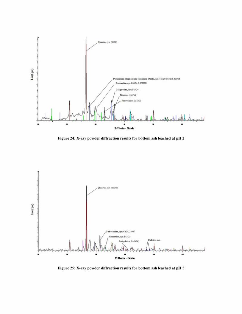
Figure 24: X-ray powder diffraction results for bottom ash leached at pH 2
Figure 25: X-ray powder diffraction results for bottom ash leached at pH 5

Figure 26: X-ray powder diffraction results for bottom ash original and leached at pH 2 and 5 respectively
Figure 37: X-ray powder diffraction results for original unleached fly ash

Figure 28: X-ray powder diffraction results for fly ash leached at pH 2
Figure 29: X-ray powder diffraction results for fly ash leached at pH-5

Figure 30: X-ray powder diffraction results for fly ash original and leached at pH 2 and 5

Chapter: 6 Discussion and Conclusions
From the experimental work it has been concluded that different factors affect Zn extraction from acid ash leachates. A start pH in the range of 3.8-5 gave the maximum fraction of Zn extracted. However, a lower pH in the leachate may give better dissolution of Zn containing compounds in the ashes. The possible solubility equilibria restricting the Zn leaching in the present work need to be investigated. At all used pH levels and with all tested ligands Fe was extracted along with Zn. Zn and Fe may be separated later in the stripping section with help of suitable acid e.g. HCl, HNO3 and H2SO4 with an optimum pH.. However, stripping was not tested in this work.
According to XRD results iron occurs as both Fe (II) and Fe (III) in the bottom ash but only as Fe (III) in the fly ash. In a parallel work X-ray absorption spectroscopy measurements were made at the synchrotron facility Maxlab in Lund, Sweden. [33] The results showed that the bottom ash sample may contain iron in oxidation state I or zero as well.
Separation of Zn(II) from Fe (II) is easier than separation from Fe (III).Thus, it is recommended that a leaching method that does not release Fe(III) is developed. More research work and experimental work needs to sort out this problem. [22]
In this thesis work three ligands Cyanex 272, Cyanex 921 and TBP were tested to extract Zn(II) . Cyanex 272 has the ability to extract Zinc from aqueous medium rich in nitrate. 94.3% of the Zn (II) in the ash leachate was extracted with 20vol%Cyanex 272 for bottom ash leachates and 88% Zn (II) was extracted with 30vol%Cyanex 272 from fly ash leachates. In some articles, research show that Cyanex 921 and TBP work efficiently if the leaching medium is HCl. However, in our case HNO3 was used for leaching and this may be one reason why these ligands did not give good results. [21, 22] The reason for not using HCl or H2SO4 during leaching of ash was to avoid precipitation of PbCl2 and PbSO4 in the solution.
The total recovery of Zn obtained in the present work is quite low and the key issue is to improve the dissolution in the first leaching step. Form the results it can be seen that if pH 4 is used in both process steps only about 20% of the Zn in the ash is recovered, but the Swiss process is said to give 60% recovery of Zn. There are some differences between the processes that may affect the zinc yield.[20]
The L/S ratio used is also an important factor that affects the release of metals in leaching. In this work L/S ratios in the order of 7 to 10 were used to keep the pH constant. It is possible that a higher L/S in the leaching step would give higher releases of Zn.
Oxidative leaching is another possible way to extract zinc with very low amount of iron being co-leached. The oxidants used in experimental work by Reza Alizadeh, Fereshteh Rashchi and Ehsan Vahidi, were H2O2 and MnO2. The oxidation decreased the leaching of iron by the formation of iron hydroxide and iron manganese compounds at pH 2.5. [23]

Further research work is needed in different parts of this project i.e.
− L/S ratio should be varied to investigate possible solubility limits. − During leaching test different acid (HCl or H2SO4) followed by extraction with TBP
could be used. − Changing of A/O ratio may increase or decrease extraction of metals. − Other ligands (D2EHPA, DPPP, DBBP, LIX 34 in kermac 470B, Cyanex 302 in
Toluene) could be used.

References
[1] Eurostat; key figures on Europe 2010 edition. page 198-199.
[2] Karin Karlfeldt Fedje. Metal in MSWI fly ash, Problems or Opportunities. 2010 Chalmers University of Technology. Goteborg, Sweden. [3] N.P. Cheremoisinoff, Hand book of solid waste management and waste minimization technologies. 2003: Elsevier Science.
[4] Tao Wang, Tingfeng Liu, Cheng Sun, Application of MSWI fly ash on acidic soil and its effect on the environment. State key laboratory of pollution control and resources reuse, school of the environment, Nanjing University, Nanjing 210093, PR china.
[5] Masashi Kamon, Takeshi Katsumi, Youichi sano, MSW fly ash stabilized with coal ash for geo technical application, Disaster prevention research (DPRI), Kyoto university Gokasho, Uji, Kyoto 6110011, Japan. Department of civil engineering, Ritsumeikan University, Kusatsu Shiga 5258477, Japan. Department of Global environment engineering, Kyoto University, sakyo, Kyoto 6068501, Japan.
[6] Evelina Brännvall, Accelerated ageing of refuse Derived Fuel (RDF) fly ash, department of civil and environmental engineering, Division of waste science and technology. ISSN:1402-1757, ISBN 978-91-7439-155-8, Luleå University of technology.
[7] Frederick Raask, Mineral impurities in coal combustion behavior, problems and remedial measures, ISBN 089116-362-X (1985).
[8] National Oceanography Centre, Southampton (NOCS),
http://www.noc.soton.ac.uk/geochem/Facilities.php.
[9] Francis Rouessac and Annick Rouessac. Chemical analysis modern instrumentation methods and techniques. 2nd Edition WILEY.
[10] A.J. Chandler, T.T. Eighmy, J.Hartlen, O. Hjelmar, D.S. Kosson, S.E. Sawell, et al., eds. Municipal Solid waste incinerator residues. 1997, Elsevier: Amsterdam; New York.
[11] J.d. Winefordner, Somenatb Mitra, Samples preparation techniques in analytical chemistry, chemical analysis: a series of monographs on analytical chemistry and its applications. P 37-38.
[12] MEAB Metallextraktion AB, Askim/Göteborg, Sweden. Product info 08-2010.
[13] MEAB Metallextraktion AB, Askim/Göteborg, Sweden. Product info 08-2010 p.2.
[14] Jan Rydberg, Acta Chemica Scandinavica 23 (1969), Solvent extraction studies by the AKUFVE method, Part 1. Principle and General Problems. P 647-650.

[15] IUP 87b V. Gold, K. L. Leoning, A. D. McNaught and P. Swhmi, Compendium of Chemical terminology. IUPAC Recommendations. Blackwell Scientific Publications, London (1987).
[16] IUPAC. Compendium of Chemical Terminology, 2nd ed. (the "Gold Book"). Compiled by A. D. McNaught and A. Wilkinson. Blackwell Scientific Publications, Oxford (1997). XML on-line corrected version: http://goldbook.iupac.org (2006-) created by M. Nic, J. Jirat, B. Kosata; updates compiled by A. Jenkins. ISBN 0-9678550-9-8.doi:10.1351/gold book.
[17] Atkins, Overton, Rourke, Weller, Armstrong, SHRIVER & ATKINS, Inorganic Chemistry. 4th Edition. (2006).p 169-171.
[18] http://www.cytec.com/specialty-chemicals/cyanex.htm#PAE.
[19] A.M.I. Ali, I.M. Ahmad, J.A. Daoud, CYANEX 272 for the extraction and recovery of zinc from aqueous waste solution using a mixer-settler unit. Separation and Purification Technology 47 (2006) 135–140.
[20] Stefan Schlumberger, Michael Schuster, Stefan Ringmann and Ralf Koralewska, Recovery of high purity zinc from filter ash produced during the thermal treatment of waste and inerting of residual materials. Waste Manag Res 2007.
[21] S.I. El Dessouky, Y.A. El-Nadi, I.M. Ahmed, E.A. Saad b, J.A. Daoud, Solvent extraction separation of Zn(II), Fe(II), Fe(III) and Cd(II) using tributylphosphate and CYANEX 921 in kerosene from chloride medium. Chemical Engineering and Processing 47 (2008) 177–183.
[22] Magdalena Regel-Rosocka and Jan Szymanowski, Iron(II) transfer to the organic phase during Znic(II) extraction from spent picling solutions with Tributyl phosphate. Taylor & Francis group, Solvent Extraction and Ion Exchange, volume 23, Number 3, 2005. P 411-415.
[23] Reza Alizadeh, Fereshteh Rashchi and Ehsan Vahidi, Recovery of Zinc from leaching residues with minimum iron dissolution using oxidative leaching. Waste Manag Res 2011- 29:165 originally published online 1 June 2010.
[24]http://www.waste-management-world.com/index/display/article-display/339838/articles/waste-management-world/volume-9/issue-4/features/waste-sorting-a-look-at-the-separation-and-sorting-techniques-in-todayrsquos-european-market.html 2011-07-10
[25] http://www.riksdagen.se/Webbnav/index.aspx?nid=3911&bet=2011:927 (regulations).
[26 http://www.naturvardsverket.se/en/In-English/Start/Products-and-waste/Waste/Management-and-treatment-of-waste/Landfilling/ (landfilling ).
[27] James R. Connolly “Introduction to X-Ray Powder Diffraction”, Published Spring 2007 for EPS400-002.
[28] Marta J.K. Flohr, “X-Ray powder diffraction”, USGS, Published for US Geological Survey, 1997.
[29] http://www.icdd.com/profile/overview.htm 2011-07-10.

[30] John R. Dean“Practical Inductively Coupled Plasma Spectroscopy”, Published by John Wiley & Sons, Ltd 2005, ISBN 0-470-09348-X.
[31] Thermo Electron Corporation, “iTEVA Software Manual for iCAP 6000 series ICP Emission Spectrometers”.
[32] http://www.chalmers.se/chem/EN/divisions/nuclear-chemistry/our-history.
[33] Steenari, B-M., Björefors, F., Norholm, S., Hedberg, D. Recovery of metals from MSWI ashes, Avfall Sverige report 2011.
[34] D. Guyonnet, F. Bodénan, G. Brons-Laot, A. Burnol, L. Chateau, M. Crest, J. Méhu, P. Moszkowicz and P. Piantone , Multiple-scale dynamic leaching of a municipal solid waste incineration ash, Accepted 1 July 2007. P 1963-1976.
[35] James E. House, ‘’Inorganic chemistry Textbook’’ Elsevier: Canada 2008. ISBN 978-0-12-356786-4 p-335.
[36] Y.K.P. Sze, L. Xue, Extraction of zinc and chromium(III) and its application to treatment of alloy electroplating wastewater, Sep. Sci. 38 (2) (2003) 405.
[37] W.A. Rickelton, R.J. Boyle, The selective recovery of zinc with new thiophosphinic acids, Solv. Extr. Ion Exch. 8 (6) (1990) p 783.
[38] Y.G. Wang, L.G. Wang, D.Q. Li, Synergistic extraction of Zinc(II) with mixtures of CA 100 and Cyanex 272, Sep. Sci. Technol. 38 (10) (2003) 2291.
[39] Q. Jia, D. Li, C. Niu, Synergistic extraction of zinc(II) by mixtures of primary amine N1923 and Cyanex 272, Solv. Extr. Ion Exch. 20 (6) (2002) 751.
[40] M. Regel. A.M. Sastre , J, Szymanawski, Recovery of zinc from HCl spent pickling solutions by solvent extraction, Environ.Sci.Technol.35(2001) p 630-635
[41] Marcelo Borges Mansur, Sonia Denise Ferreira Rocha, Fernando Silva Magalhaes, Jeaneth dos Santos Benedetto, Selective extraction of zinc(II) over iron(II) from spent hydrochloric acid pickling effluents by liquid–liquid extraction, Journal of Hazardous Materials 150 (2008) 669–678.
[42] Fazlul Bari, Noorzahan Begum, Samsul Baharin Jamaludin and Kamaru din Hussin. Extraction and separation of Cu(II), Ni(II) and Zn(II) by sol–gel silica immobilized with Cyanex 272, Hydrometallurgy 96 (2009) 140–147.
[43] Aleksandra Borowiak Resterna, Honorata Chlebowska and Michal Giezek. Zinc extraction from chloride solutions with N-alkyl- and N,N-dialkylpyridine carboxamides.
[44] Weng Fu, Qiyuan Chen, Qian Wu, Huiping Hu and Lan Bai. Solvent extraction of zinc from ammoniacal/ammonium chloride solutions by a sterically hindered β-diketone and its mixture with tri-n-octylphosphine oxide. Hydrometallurgy 100 (2010) 116-121.

[45] M.C. Camerani-Pinzani, B. Golosio, A. Somogyi, A.S. Simionovici, B.-M Steenari , I. Panas, X-ray fluorescence tomography of individual municipal solid waste and biomass fly ash particles. Analytical Chemistry, 76(6).(2004) p.1586-1595.
[46] E. Fujimori, R. Shiozawa, S. Iwata, K. Chiba and H. Haraguchi, Multi element and morphological characterization of industrial waste incineration fly ash as studied by ICP-AES/ICP-MS and SEM-EDS, Bulletin of Chemical Society of Japan. 75. (2002) p.1205-1213.

Appendix
Table A Zinc & Iron Concentration in leachates (mg/liter)
Fly ash Bottom ash
pH Conc. of Fe in mg/lit Conc. of Zn in mg/lit Conc. of Fe in mg/lit Conc. of Zn in mg/lit
2 110 535 1430 140 3 150 560 690 60 4 2.5 525 110 50 5 1.5 320 2 15
Table B Amounts of Zn and Fe removed from ash samples during leaching experiments calculated as mg of metal
per kg dry ash.
Fly ash Bottom ash
pH Fe in mg/kg ash Zn in mg/kg ash Fe in mg/kg ash Zn in mg/kg ash
2 1900 8900 23900 2280 3 2600 9360 11400 1000 4 40 8760 1860 810 5 20 5260 20 250
Table C D-values of zinc and iron
30 vol % Cyanex 272
Start
pH
Fe Bottom ash Zn Bottom ash Fe fly ash Zn fly ash
5 4 1 7 8 4 840 7 69 3 3 4 1 56 2 2 2 1 37 1
20 vol % Cyanex 272
Start
pH
Fe Bottom ash Zn Bottom ash Fe fly ash Zn fly ash
5 23 6 34 5 4 580 17 8 2 3 3 1 57 1 2 1 1 38 1
Cyanex 921+ 5% Octanol
Start
pH
Fe Bottom ash Zn Bottom ash Fe fly ash Zn fly ash
5 0 - 9.9 0.2 4 14 0.1 27 0.2 3 0.5 - Gel Gel 2 0.3 0.1 0.3 0.2
TBP
Start
pH
Fe Bottom ash Zn Bottom ash Fe fly ash Zn fly ash

5 0.8 - 27 0.0 4 - - - 0.0 3 0.1 - - - 2 0.1 0.1 - -
Table D Concentration of Zn and Fe in mmol/lit of leachate from Bottom ash
BOTTOM ASH
PH-5
mmol/l
it
BOTTOM ASH
PH-4 mmol/lit BOTTOM ASH
PH-3 mmol/l
it
BOTTOM ASH
PH-2 mmol/l
it
Fe from original
ash
0 Fe from original
ash
3 Fe from original
ash
21 Fe from original
ash
54
Zn from original
ash
0.3 Zn from original
ash
2 Zn from original
ash
2 Zn from original
ash
6
BOTTOM ASH
PH-5 C272 30%
BOTTOM ASH
PH-4 C272 30%
BOTTOM ASH
PH-3 C272 30%
BOTTOM ASH
PH-2 C272 30%
Fe 0 Fe 0 Fe 4 Fe 22
Zn 0.1 Zn 0.3 Zn 1 Zn 3
BOTTOM ASH
PH-5 C272 20%
BOTTOM ASH
PH-4 C272 20%
BOTTOM ASH
PH-3 C272 20%
BOTTOM ASH
PH-2 C272 20%
Fe 0 Fe 0 Fe 5 Fe 27
Zn 0 Zn 0.1 Zn 1 Zn 3
BOTTOM ASH
PH-5 C 921
BOTTOM ASH
PH-4 C 921
BOTTOM ASH
PH-3 C 921
BOTTOM ASH
PH-2 C 921
Fe 0 Fe 0.2 Fe 15 Fe 43
Zn 0.7 Zn 2 Zn 2 Zn 6
BOTTOM ASH
PH-5 TBP
BOTTOM ASH
PH-4 TBP
BOTTOM ASH
PH-3 TBP
BOTTOM ASH
PH-2 TBP
Fe 0.02 Fe 3 Fe 20 Fe 48
Zn 0.8 Zn 2 Zn 2 Zn 6

Table E Concentration of Zn and Fe in mmol/lit of leachate from fly ash
FLY ASH
PH-5
mmol/
lit
FLY ASH
PH-4 mmol/li
t
FLY ASH
PH-3 mmol/
lit
FLY ASH
PH-2 mmol/
lit
Fe from original
ash
0.04 Fe from
original ash
0.07 Fe from original
ash
5 Fe from original
ash
4
Zn from original
ash
9 Zn from
original ash
18 Zn from original
ash
23 Zn from original
ash
29
FLY ASH PH-5
C272 30%
FLY ASH PH-4
C272 30%
FLY ASH PH-3
C272 30%
FLY ASH PH-2
C272 30%
Fe 0 Fe 0 Fe 0.08 Fe 0.1
Zn 1 Zn 5 Zn 9 Zn 16
FLY ASH PH-5
C272 20%
FLY ASH PH-4
C272 20%
FLY ASH PH-3
C272 20%
FLY ASH PH-2
C272 20%
Fe 0 Fe 0 Fe 0.08 Fe 0.1
Zn 1 Zn 6 Zn 10 Zn 16
FLY ASH PH-5
C 921
FLY ASH PH-4
C 921
FLY ASH PH-3
C 921
FLY ASH PH-2
C 921
Fe 0 Fe 0.2 Fe gel Fe 3
Zn 8 Zn 16 Zn gel Zn 24
FLY ASH PH-5
TBP
FLY ASH PH-4
TBP
FLY ASH PH-3
TBP
FLY ASH PH-2
TBP
Fe 0 Fe 0.07 Fe 5 Fe 7
Zn 9 Zn 17 Zn 23 Zn 29
*C272 = CYANEX 272 , Bis (2, 4, 4-trimethylpentyl phosphinic acid)
** C921= CYANEX 921, Trioctyl phosphine oxides
***TBP= Tributyl phosphate
**** D-Fe and D-Zn mean D-value