Embed Size (px)
Citation preview
Version 1.4
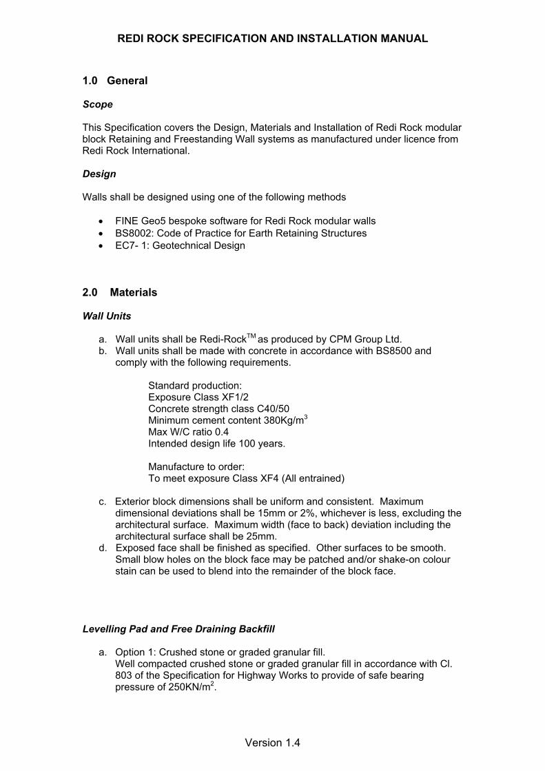
Redi Rock Specification and Installation Manual
REDI ROCK SPECIFICATION AND INSTALLATION MANUAL
Version 1.4
1.0 General Scope This Specification covers the Design, Materials and Installation of Redi Rock modular block Retaining and Freestanding Wall systems as manufactured under licence from Redi Rock International. Design Walls shall be designed using one of the following methods
• FINE Geo5 bespoke software for Redi Rock modular walls • BS8002: Code of Practice for Earth Retaining Structures • EC7- 1: Geotechnical Design
2.0 Materials Wall Units
a. Wall units shall be Redi-RockTM as produced by CPM Group Ltd. b. Wall units shall be made with concrete in accordance with BS8500 and
comply with the following requirements.
Standard production: Exposure Class XF1/2 Concrete strength class C40/50 Minimum cement content 380Kg/m3 Max W/C ratio 0.4 Intended design life 100 years.
Manufacture to order: To meet exposure Class XF4 (All entrained)
c. Exterior block dimensions shall be uniform and consistent. Maximum
dimensional deviations shall be 15mm or 2%, whichever is less, excluding the architectural surface. Maximum width (face to back) deviation including the architectural surface shall be 25mm.
d. Exposed face shall be finished as specified. Other surfaces to be smooth. Small blow holes on the block face may be patched and/or shake-on colour stain can be used to blend into the remainder of the block face.
Levelling Pad and Free Draining Backfill
a. Option 1: Crushed stone or graded granular fill. Well compacted crushed stone or graded granular fill in accordance with Cl. 803 of the Specification for Highway Works to provide of safe bearing pressure of 250KN/m2.
REDI ROCK SPECIFICATION AND INSTALLATION MANUAL
Version 1.4
Option 2: Concrete foundation To the requirements of BS8500 Designated Concrete GEN1 for mass, RC30 for reinforced.
b. Free draining backfill material to be granular, well draining sand or stone in accordance with Cl 513 ‘Permeable backfill to Earth Retaining Structures’ of the Specification for Highway Works. It shall be placed to a minimum of 300mm width behind the back of the wall and shall extend vertically from the foundation pad to an elevation 100mm below the top of wall.
c. Backfill material shall be approved by the geotechnical engineer. Site excavated soils may be used if approved unless otherwise specified in the drawings.
d. Unsuitable soils with a PI>6, organic soils and frost susceptible soils shall not be used within a 1 to 1 influence area.
e. non-woven geotextile cloth shall be placed between the Free Draining Backfill and retained soil if required.
f. Where additional fill is needed, contractor shall submit sample and specifications to the Engineer for approval.
Drainage
a. Internal and external drainage shall be evaluated by the Professional Engineer who is responsible for the final wall.
Foundations Excavation Contractor shall excavate to the lines and grades shown on the construction drawings. Foundation Soil Preparation
a. Native foundation soil shall be compacted to 95% of standard proctor or 90% of modified proctor prior to placement of the levelling Pad material.
b. In-situ foundation soil shall be examined by the engineer, to ensure that the actual foundation soil strength meets or exceeds assumed design strength. Soil not meeting the required strength shall be removed and replaced with acceptable compacted material.
Granular Foundation
a. Foundation pad shall be placed as shown on the construction drawings. b. Foundation pad shall be placed on undisturbed native soils or suitable
replacements fills. c. Foundation pad shall be constructed to the proper elevation to ensure the
final elevation shown on the plans. Well-graded sand may be used to smooth the top 15mm on the Foundation Pad.
d. Granular Foundation Pad shall have a 150mm minimum depth for walls under 2.44m in height and a 300mm minimum depth for walls over 2.44m. Pad dimensions shall extend beyond the blocks in all directions to a distance at least equal to the depth of the pad or as designed by engineer.
e. For steps and pavers, a minimum of 25mm – 40mm of free draining sand shall be screeded smooth to act as a placement bed for the steps or pavers.
f. Base material to be compacted to minimum 95% standard proctor density.
REDI ROCK SPECIFICATION AND INSTALLATION MANUAL
Version 1.4
Concrete Foundation
a. Concrete to be laid in accordance with the dimension on the construction drawings.
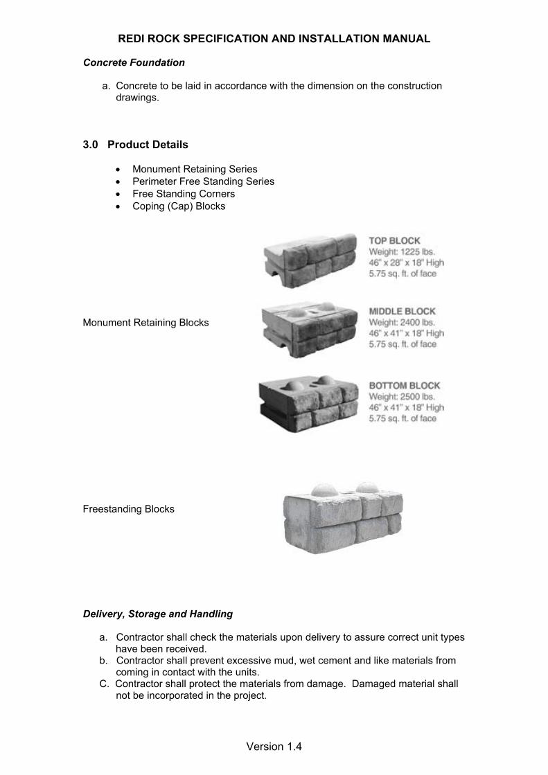
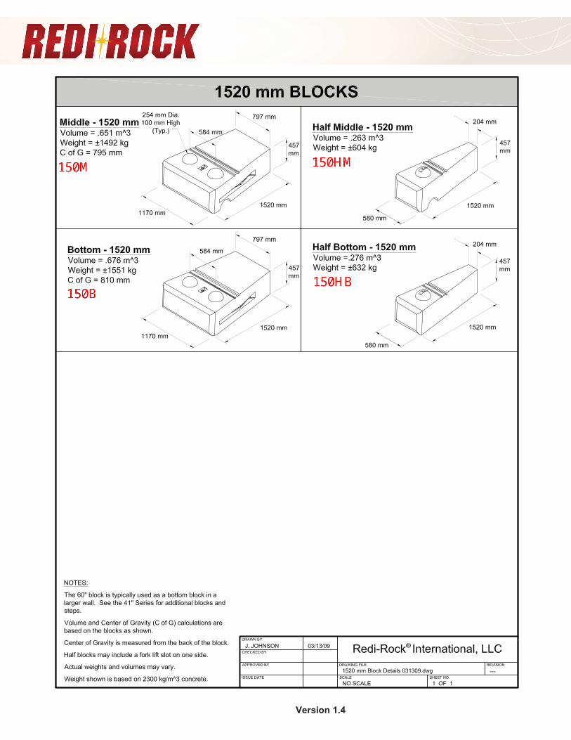
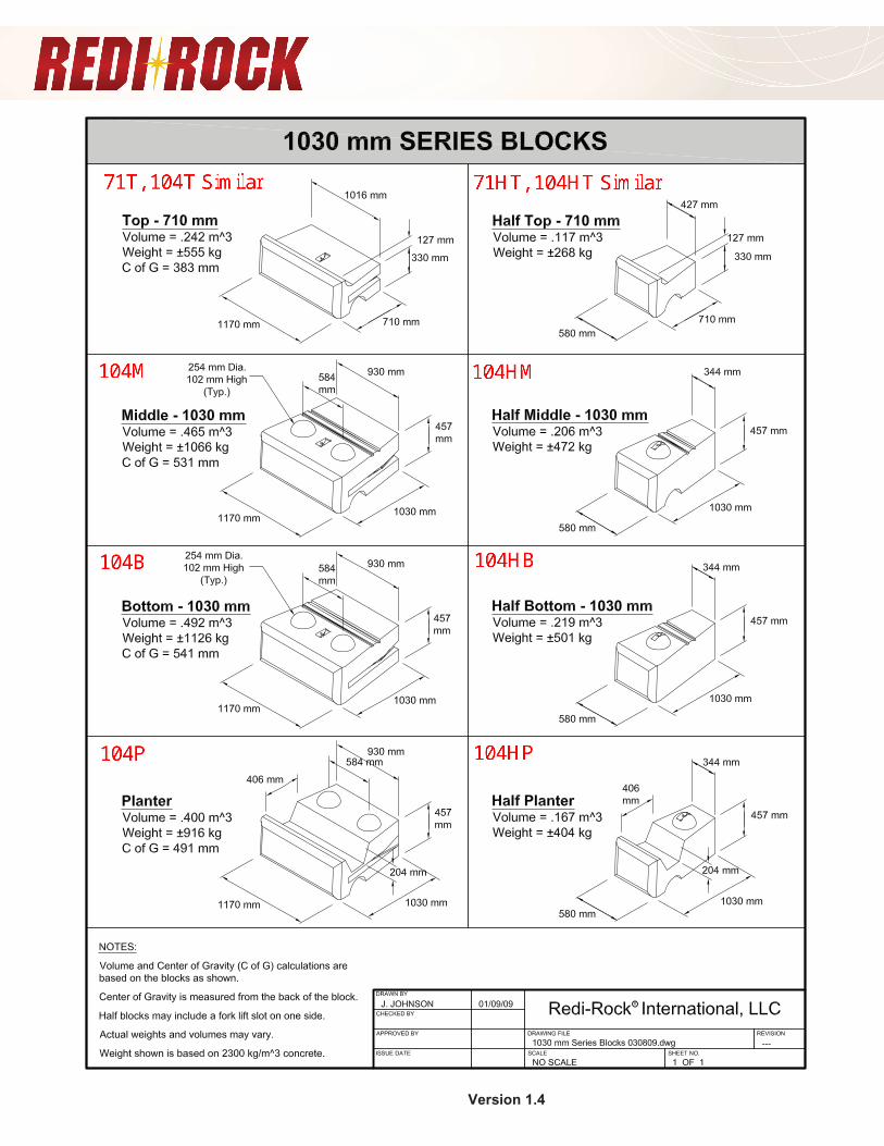
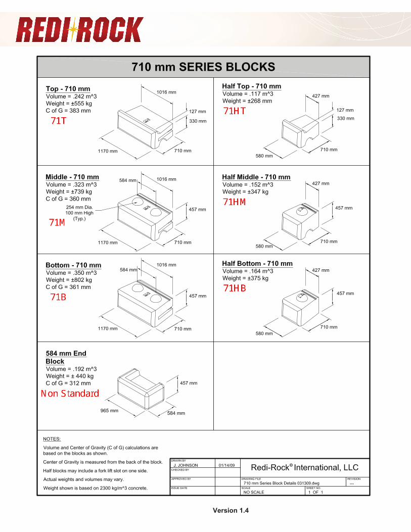
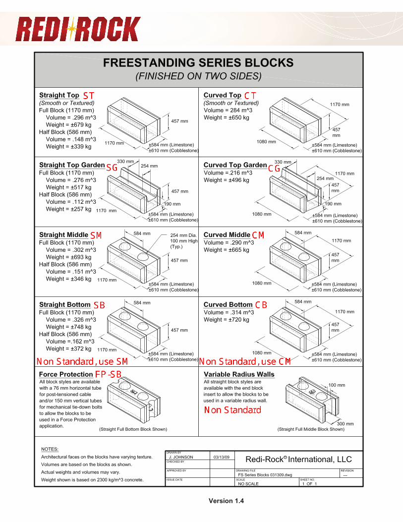
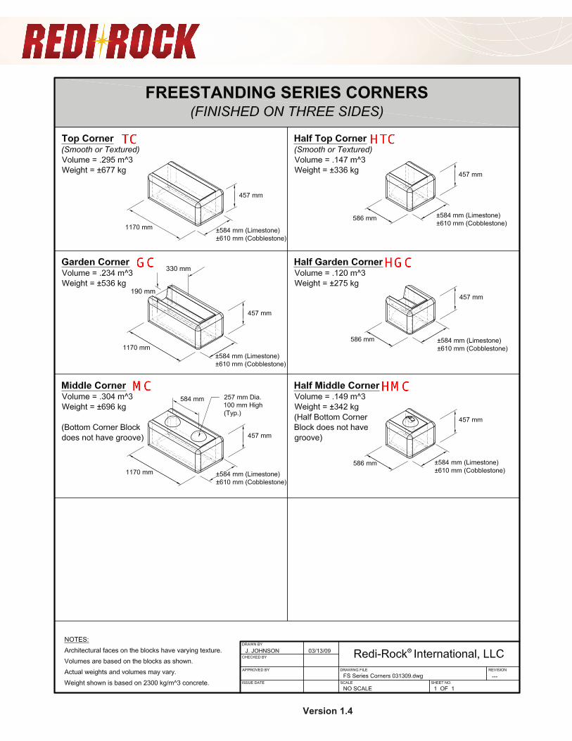
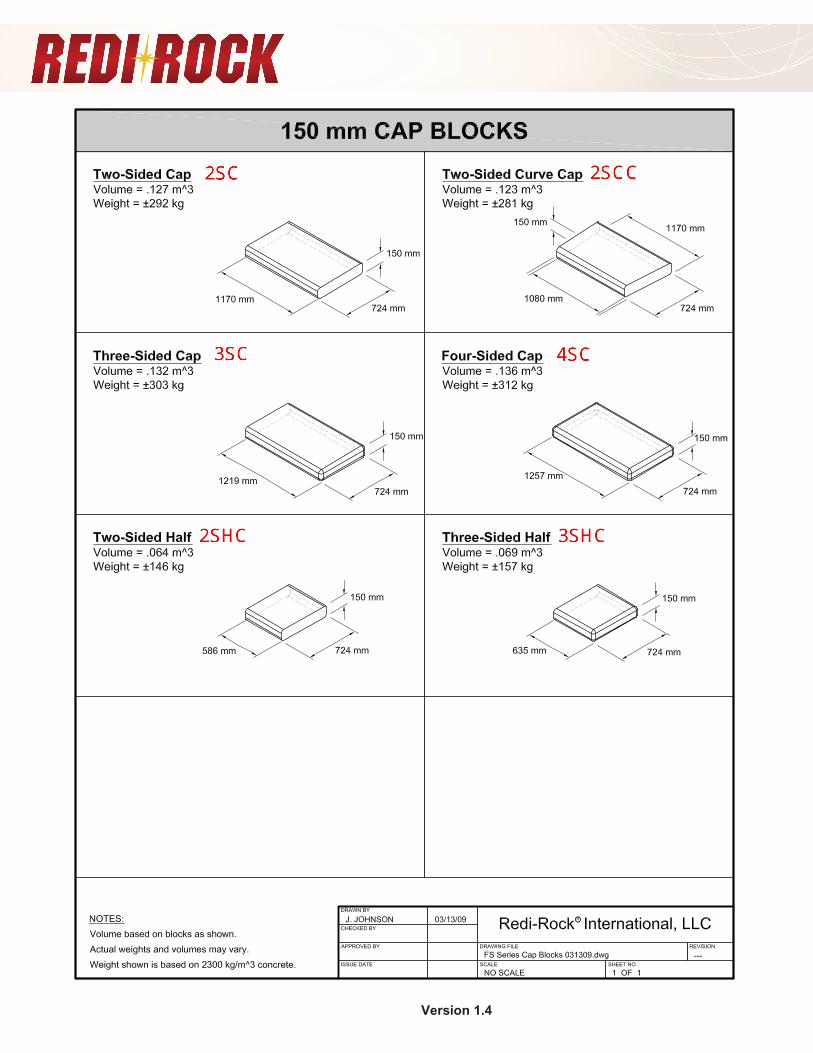
3.0 Product Details
• Monument Retaining Series • Perimeter Free Standing Series • Free Standing Corners • Coping (Cap) Blocks
Monument Retaining Blocks Freestanding Blocks Delivery, Storage and Handling
a. Contractor shall check the materials upon delivery to assure correct unit types
have been received. b. Contractor shall prevent excessive mud, wet cement and like materials from
coming in contact with the units. C. Contractor shall protect the materials from damage. Damaged material shall
not be incorporated in the project.
Version 1.4
Version 1.4
Version 1.4
Version 1.4
Version 1.4
Version 1.4
REDI ROCK SPECIFICATION AND INSTALLATION MANUAL
Version 1.4
4.0 Wall Construction Installing Monument Retaining Wall Blocks:
a. The first course of wall units shall be placed on the prepared levelling pad with the aesthetic surface facing out and the front edges tight together. All units shall be checked for level and alignment as they are placed.
b. Ensure that units are in full contact with Foundation Pad. Proper care shall be taken to develop straight lines and smooth curves on base course as per wall layout.
c. The backfill in front and back of entire base row shall be placed and compacted to firmly lock them in place. Check all units again for level and alignment. All excess material shall be swept from top of units.
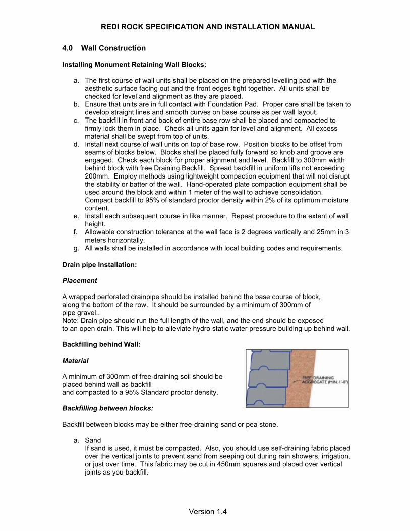
d. Install next course of wall units on top of base row. Position blocks to be offset from seams of blocks below. Blocks shall be placed fully forward so knob and groove are engaged. Check each block for proper alignment and level. Backfill to 300mm width behind block with free Draining Backfill. Spread backfill in uniform lifts not exceeding 200mm. Employ methods using lightweight compaction equipment that will not disrupt the stability or batter of the wall. Hand-operated plate compaction equipment shall be used around the block and within 1 meter of the wall to achieve consolidation. Compact backfill to 95% of standard proctor density within 2% of its optimum moisture content.
e. Install each subsequent course in like manner. Repeat procedure to the extent of wall height.
f. Allowable construction tolerance at the wall face is 2 degrees vertically and 25mm in 3 meters horizontally.
g. All walls shall be installed in accordance with local building codes and requirements. Drain pipe Installation: Placement A wrapped perforated drainpipe should be installed behind the base course of block, along the bottom of the row. It should be surrounded by a minimum of 300mm of pipe gravel.. Note: Drain pipe should run the full length of the wall, and the end should be exposed to an open drain. This will help to alleviate hydro static water pressure building up behind wall. Backfilling behind Wall: Material A minimum of 300mm of free-draining soil should be placed behind wall as backfill and compacted to a 95% Standard proctor density. Backfilling between blocks: Backfill between blocks may be either free-draining sand or pea stone.
a. Sand If sand is used, it must be compacted. Also, you should use self-draining fabric placed over the vertical joints to prevent sand from seeping out during rain showers, irrigation, or just over time. This fabric may be cut in 450mm squares and placed over vertical joints as you backfill.
REDI ROCK SPECIFICATION AND INSTALLATION MANUAL
Version 1.4
b. Stone
If a 30mm stone is used to backfill between blocks then no fabric is necessary. Installing Planter blocks:
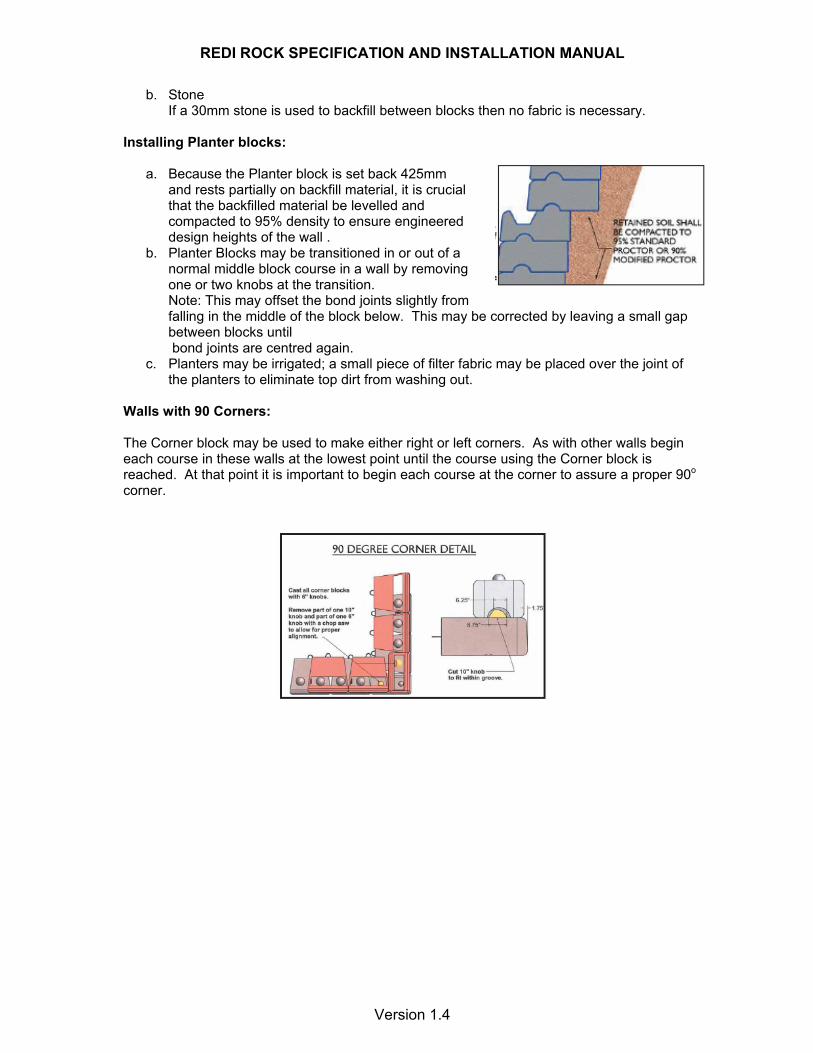
a. Because the Planter block is set back 425mm and rests partially on backfill material, it is crucial
that the backfilled material be levelled and compacted to 95% density to ensure engineered design heights of the wall . b. Planter Blocks may be transitioned in or out of a
normal middle block course in a wall by removing one or two knobs at the transition. Note: This may offset the bond joints slightly from falling in the middle of the block below. This may be corrected by leaving a small gap between blocks until bond joints are centred again.
c. Planters may be irrigated; a small piece of filter fabric may be placed over the joint of the planters to eliminate top dirt from washing out.
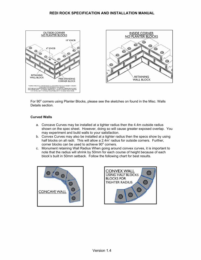
Walls with 90 Corners: The Corner block may be used to make either right or left corners. As with other walls begin each course in these walls at the lowest point until the course using the Corner block is reached. At that point it is important to begin each course at the corner to assure a proper 90o corner.
REDI ROCK SPECIFICATION AND INSTALLATION MANUAL
Version 1.4
For 90o corners using Planter Blocks, please see the sketches on found in the Misc. Walls Details section. Curved Walls
a. Concave Curves may be installed at a tighter radius then the 4.4m outside radius shown on the spec sheet. However, doing so will cause greater exposed overlap. You may experiment and build walls to your satisfaction.
b. Convex Curves may also be installed at a tighter radius then the specs show by using half blocks on all radii. This will allow a 2.4m’ radius for outside corners. Further, corner blocks can be used to achieve 90o corners.
c. Monument retaining Wall Radius When going around convex curves, it is important to note that the radius will shrink by 50mm for each course of height because of each block’s built in 50mm setback. Follow the following chart for best results.
REDI ROCK SPECIFICATION AND INSTALLATION MANUAL
Version 1.4
Perimeter Free-Standing Walls: For best results in placing Perimeter Free-Standing Walls, the following procedures are recommended.
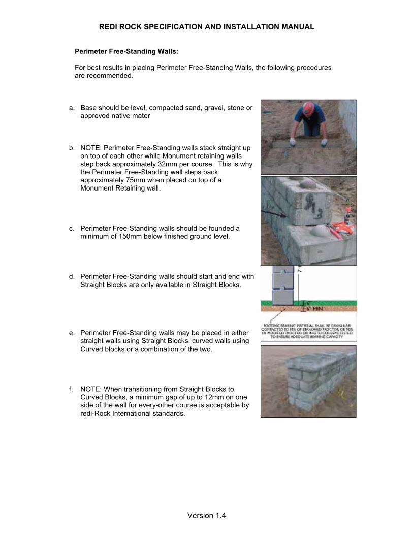
a. Base should be level, compacted sand, gravel, stone or approved native mater
b. NOTE: Perimeter Free-Standing walls stack straight up
on top of each other while Monument retaining walls step back approximately 32mm per course. This is why the Perimeter Free-Standing wall steps back approximately 75mm when placed on top of a Monument Retaining wall.
c. Perimeter Free-Standing walls should be founded a
minimum of 150mm below finished ground level. d. Perimeter Free-Standing walls should start and end with
Straight Blocks are only available in Straight Blocks. e. Perimeter Free-Standing walls may be placed in either
straight walls using Straight Blocks, curved walls using Curved blocks or a combination of the two.
f. NOTE: When transitioning from Straight Blocks to
Curved Blocks, a minimum gap of up to 12mm on one side of the wall for every-other course is acceptable by redi-Rock International standards.
REDI ROCK SPECIFICATION AND INSTALLATION MANUAL
Version 1.4
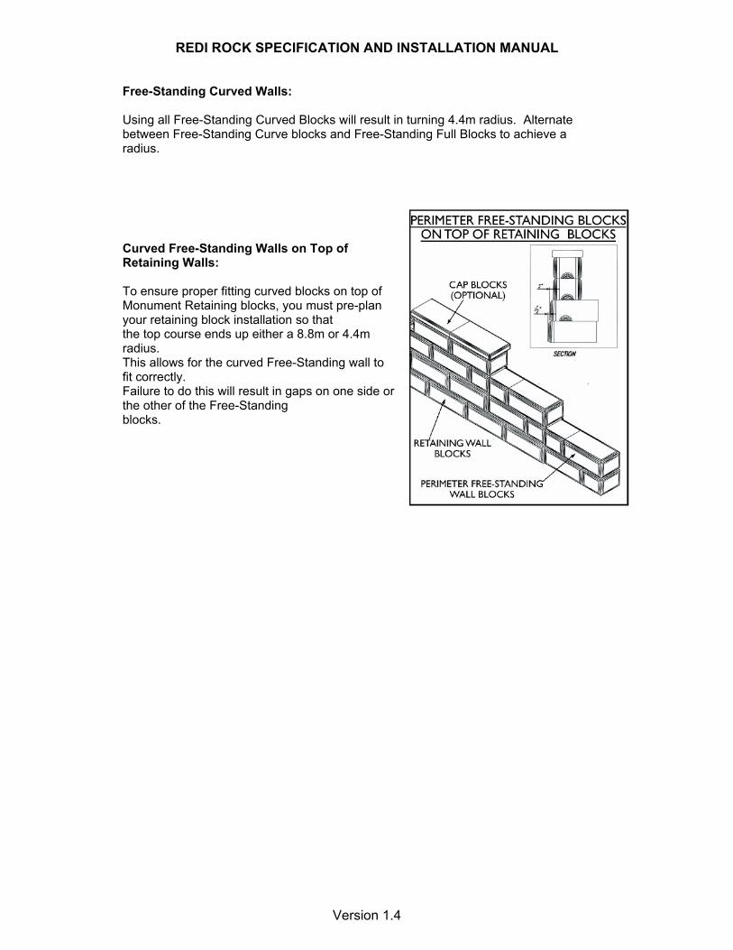
Free-Standing Curved Walls: Using all Free-Standing Curved Blocks will result in turning 4.4m radius. Alternate between Free-Standing Curve blocks and Free-Standing Full Blocks to achieve a radius. Curved Free-Standing Walls on Top of Retaining Walls: To ensure proper fitting curved blocks on top of Monument Retaining blocks, you must pre-plan your retaining block installation so that the top course ends up either a 8.8m or 4.4m radius. This allows for the curved Free-Standing wall to fit correctly. Failure to do this will result in gaps on one side or the other of the Free-Standing blocks.
REDI ROCK SPECIFICATION AND INSTALLATION MANUAL
Version 1.4
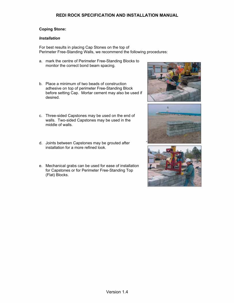
Coping Stone: Installation
For best results in placing Cap Stones on the top of Perimeter Free-Standing Walls, we recommend the following procedures:
a. mark the centre of Perimeter Free-Standing Blocks to
monitor the correct bond beam spacing. b. Place a minimum of two beads of construction
adhesive on top of perimeter Free-Standing Block before setting Cap. Mortar cement may also be used if desired.
c. Three-sided Capstones may be used on the end of
walls. Two-sided Capstones may be used in the middle of walls.
d. Joints between Capstones may be grouted after
installation for a more refined look. e. Mechanical grabs can be used for ease of installation
for Capstones or for Perimeter Free-Standing Top (Flat) Blocks.

REDI ROCK SPECIFICATION AND INSTALLATION MANUAL
Version 1.4
5.0 Site Construction Tolerances
a. Vertical Alignment: Plus or minus 40mm over any 3m distance, with a maximum differential of 75mm over the length of the wall.
b. Horizontal Alignment: • Straight Lines: Plus or minus 40mm inches over any
3m distance. • Corner and Radius Locations: Plus or minus 300mm • Curves and Serpentine Radii: plus or minus 600mm.
c. Bulging: Plus or minus 30mm over any 3m distance. 6.0 Health and Safety All due care should be undertaken to ensure the safety of the installation crew during the block installation and the finishing phase. Requirements will vary from site to site and depend on the wall design however the following general measures should be considered Generally edge protection is required which can be provided by means of vertical scaffold poles placed in the backfill at approximately 5m centres and horizontal poles fixed to the uprights. Operatives can wear a safety harness which is secured to the horizontal rail by means of a zone restriction lanyard. The horizontal can be raised accordingly as the wall height increases. The provision of air bags at the front toe of the wall can also be considered. 7.0 Maintenance
a. Redi Rock Walls are generally maintenance free however if any remedial work is required the following is advised.
b. For cleaning or stain removal a general purpose industrial detergent and
water should be used. Cleansing acid is not advised as it can be detrimental to the surface.
c. Minor concrete repairs can be carried out using a non-shrink repair mortar.
d. For major repairs contact CPM Group ltd Technical Department.