Embed Size (px)
Citation preview
COTO TECHNOLOGY, INC.For most recent data visit www.cotorelay.com
REED SWITCHES
Technical & Applications Information
COTO TECHNOLOGY, INC.For most recent data visit www.cotorelay.com
08082017
tel: (401) 943.2686 | fax: (401) 942.0920
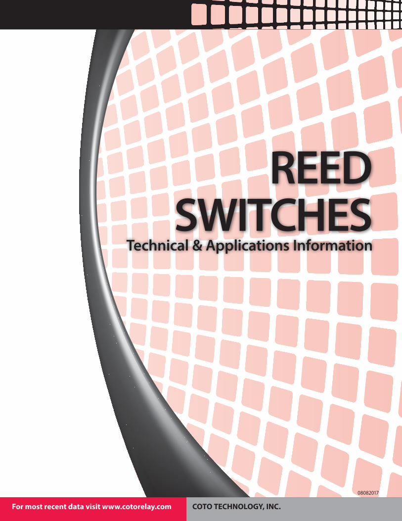
Standard packaging for uncut Reed Switches is a box containing 500 pieces. Standard packaging for SMD Reed Switches is Tape & Reel. Special trays and/or Tape & Reel are available for some types.
Contact your local Coto Technology Representative with your special packaging needs. Below is a chart of Tape & Reel dimensions for standard products.
SWITCH TECHNICAL & APPLICATIONS INFORMATIONREED SWITCH PACKAGING
DIRECTION OF FEED
102MM4.0"
330MM13"
13MM.512
2.72 MM.107
D
BD
C
E A
FIGURE 1
A
B
C
D
Fig. 1
tel: (401) 943.2686 | fax: (401) 942.0920
Series A B C D E Std. Qty/ReelCT05 G1 2.57 10.92 8.00 24.00 2.59 2000
CT05 “J1” 2.57 8.64 8.00 16.00 2.59 2000
CT10 A2, G1 2.68 16.90 8.00 32.00 3.30 2000
CT10 G2 3.00 19.80 8.00 32.00 3.12 2000
CT10 G4 3.00 19.80 8.00 32.00 3.12 2000 (Dimensions in Millimeters)
Recommended Pad Layouts for SMD Reed Relay SwitchesModel Lead Type Fig. # Dim. A Dim. B Dim. C Dim. D
CT05 G1 1 .424/10.76 .242/6.14 .091/2.31 .057/1.45
CT05 “J1” 1 .330/8.38 .168/4.27 .081/2.06 .057/1.45
CT10 A2 1 .666/16.92 .529/13.44 .069/1.74 .050/1.27
CT10 G1 1 .692/17.57 .520/13.20 .086/2.18 .041/1.04
CT10 G2 1 .822/20.87 .640/16.25 .091/2.31 .057/1.45
CT10 G4 1 .822/20.87 .640/16.25 .091/2.31 .057/1.45 (Dimensions in Inches/Millimeters)
08082017
COTO TECHNOLOGY, INC.For most recent data visit www.cotorelay.com
Dry-Reed Switch: A dry-reed switch is an assembly containing ferromagnetic contact blades, hermetically sealed in a glass envelope and operated by an externally-generated magnetic field, e.g., that from an actuating coil.
Operate Value: The ampere turn value at which normally-open contacts close. Lower value reflects higher sensitivity.
Operate Time: The operate time is the time between the instant of application of a magnetic field to a dry-reed switch and the instant of the first physical closing of this switch. The operate time does not include bounce time.
Release Value: The ampere turn value at which normally-open contacts, held closed by a magnetic field, will reopen as field strength is reduced.
Release Time: The release time is the time between the instant of removal of an applied magnetic field to a dry-reed switch and the instant of the first physical opening of this switch. The release time does not include bounce time.
Bounce: Bounce is a momentary opening of a switch after initial closing, or a momentary closing after initial opening.
Bounce Time: The bounce time is the interval of time between the instant of initial closing (or opening) and the instant of final clos-ing (or opening) of the dry-reed switch.
Dry-Reed Switch Contact Resistance: The dry-reed switch contact resistance is the resistance of the dry-reed switch under specified conditions of measurement.
Saturate Value: The saturate value is defined as the value of the applied magnetic field at which the dry-reed switch is unaffected by further increase of the applied magnetic field.
GLOSSARY OF TERMS
COTO TECHNOLOGY, INC.For most recent data visit www.cotorelay.com
08082017
tel: (401) 943.2686 | fax: (401) 942.0920
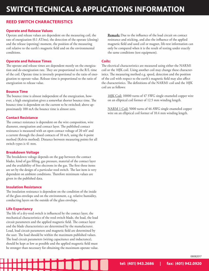
Operate and Release ValuesOperate and release values are dependent on the measuring coil, the rate of energization (0.1 AT/ms), the detection of the operate (closing) and the release (opening) moment, the position of the measuring coil relative to the earth’s magnetic field and on the environmental conditions.
Operate and Release TimesThe operate and release times are dependent mostly on the energiza-tion and de-energization rate. They are proportional to the R/L time of the coil. Operate time is inversely proportional to the ratio of ener-gization to operate value. Release time is proportional to the ratio of energization to release value.
Bounce TimeThe bounce time is almost independent of the energization, how-ever, a high energization gives a somewhat shorter bounce time. The bounce time is dependent on the current to be switched; above ap-proximately 100 mA the bounce time is almost zero.
Contact ResistanceThe contact resistance is dependent on the wire composition, wire diameter, energization and contact layer. The published contact resistance is measured with an open contact voltage of 20 mV and a current through the closed contacts of 10 mA, using the 4-point method (Kelvin method). Distance between measuring points for all switch types is 41 mm.
Breakdown VoltageThe breakdown voltage depends on the gap between the contact blades, kind of gas filling, gas pressure, material of the contact layer and the availability of free electrons in the gas. The first three items are set by the design of a particular reed switch. The last item is very dependent on ambient conditions. Therefore minimum values are given in the published data.
Insulation ResistanceThe insulation resistance is dependent on the condition of the inside of the glass envelope and on the environment, e.g. relative humidity, conducting layers on the outside of the glass envelope.
Life ExpectancyThe life of a dry-reed switch is influenced by the contact layer, the mechanical characteristics of the reed switch blade, the load, the load circuit parameters and the applied magnetic field. The contact layer and the blade characteristics are determined by the manufacturer. Load, load circuit parameters and magnetic field are determined by the user. The load should be within the maximum published values. The load circuit parameters (wiring capacitance and inductance), should be kept as low as possible and the applied magnetic field must be stronger than necessary for obtaining the maximum operate value.
Remark: Due to the influence of the load circuit on contact resistance and sticking, and also the influence of the applied magnetic field and used coil or magnet, life-test information can only be compared when it is the result of testing under exactly the same conditions (test equipment).
Coils:The electrical characteristics are measured using either the NARM1 coil or the 10JK coil. Using another coil may change these character-istics. The measuring method e.g. speed, detection and the position of the coil with respect to the earth’s magnetic field may also affect the characteristics. The definitions of the NARM1 coil and the 10JK coil are as follows:
10JK Coil: 10000 turns of 47 SWG single enameled copper wire on an elliptical coil former of 12.5 mm winding length.
NARM 1 Coil: 5000 turns of 46 AWG single enameled copper wire on an elliptical coil former of 10.4 mm winding length.
REED SWITCH CHARACTERISTICS
SWITCH TECHNICAL & APPLICATIONS INFORMATION
tel: (401) 943.2686 | fax: (401) 942.0920
08082017
COTO TECHNOLOGY, INC.For most recent data visit www.cotorelay.com
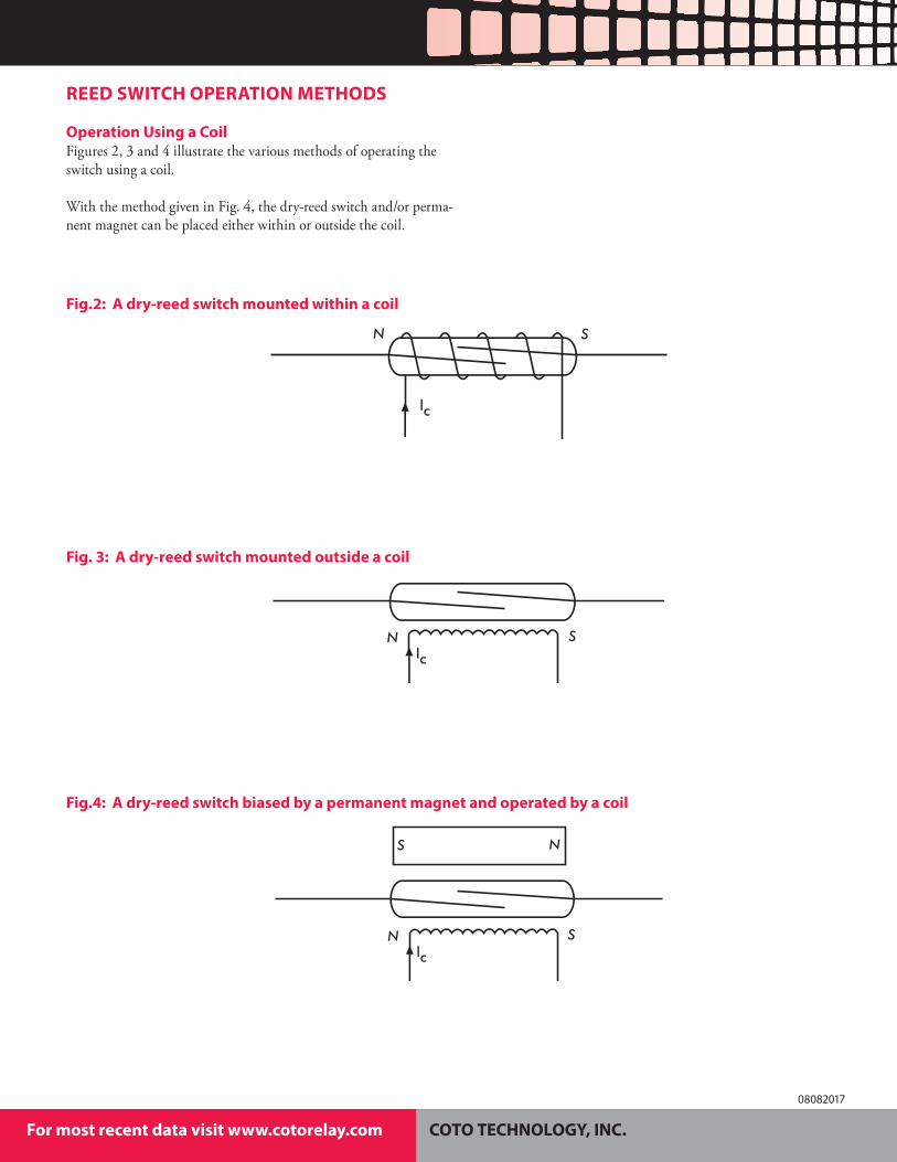
Operation Using a CoilFigures 2, 3 and 4 illustrate the various methods of operating the switch using a coil.
With the method given in Fig. 4, the dry-reed switch and/or perma-nent magnet can be placed either within or outside the coil.
REED SWITCH OPERATION METHODS
Fig. 3: A dry-reed switch mounted outside a coil
N Slc
Fig.4: A dry-reed switch biased by a permanent magnet and operated by a coil
N
N
S
S
lc
Fig.2: A dry-reed switch mounted within a coil
N S
lc
COTO TECHNOLOGY, INC.For most recent data visit www.cotorelay.com
08082017
tel: (401) 943.2686 | fax: (401) 942.0920
SWITCH TECHNICAL & APPLICATIONS INFORMATION
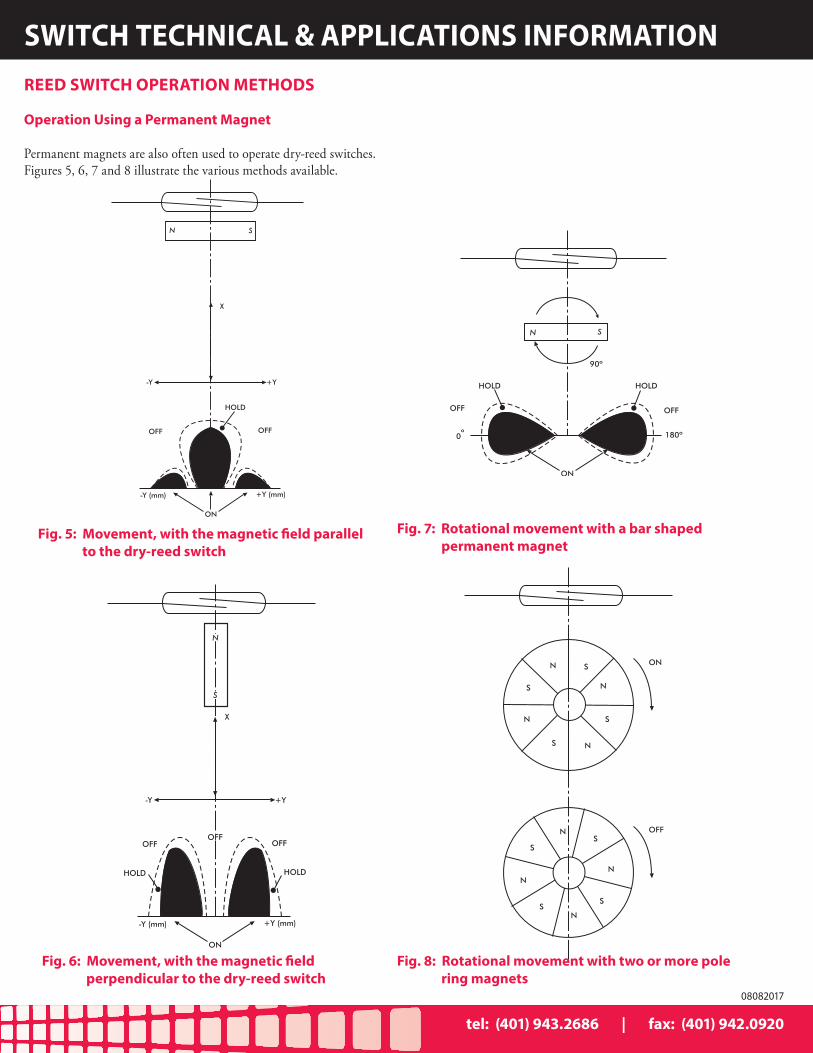
Operation Using a Permanent Magnet
Permanent magnets are also often used to operate dry-reed switches. Figures 5, 6, 7 and 8 illustrate the various methods available.
REED SWITCH OPERATION METHODS
Fig. 6: Movement, with the magnetic field perpendicular to the dry-reed switch
N
S
X
-Y +Y
OFF OFF
HOLD HOLD
-Y (mm) +Y (mm)
ON
OFF
Fig. 8: Rotational movement with two or more pole ring magnets
N
N
S
N
N
S
S
S ON
OFFNS
N
S
NS
N
S
Fig. 5: Movement, with the magnetic field parallel to the dry-reed switch
N S
X
-Y +Y
OFF OFF
HOLD
-Y (mm) +Y (mm)
ON
Fig. 7: Rotational movement with a bar shaped permanent magnet
N S
OFF OFF
HOLD HOLD
ON
0 180º
90º
º
tel: (401) 943.2686 | fax: (401) 942.0920
08082017
COTO TECHNOLOGY, INC.For most recent data visit www.cotorelay.com
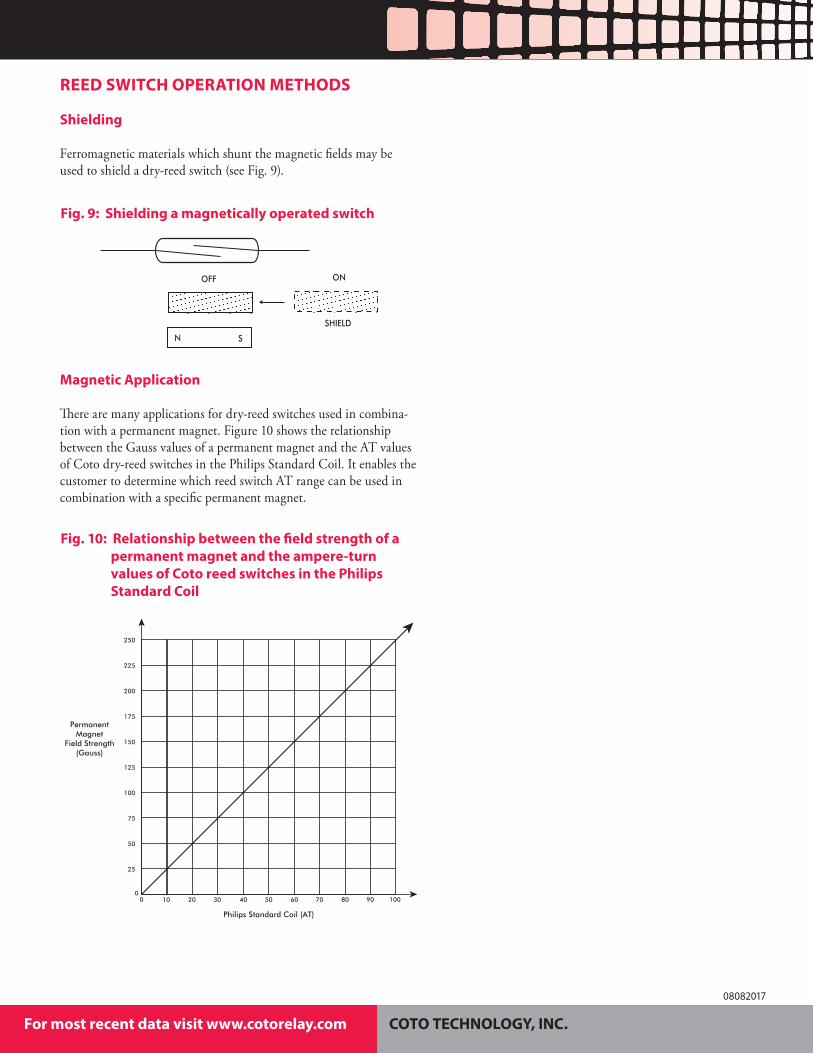
Shielding
Ferromagnetic materials which shunt the magnetic fields may be used to shield a dry-reed switch (see Fig. 9).
Magnetic Application
There are many applications for dry-reed switches used in combina-tion with a permanent magnet. Figure 10 shows the relationship between the Gauss values of a permanent magnet and the AT values of Coto dry-reed switches in the Philips Standard Coil. It enables the customer to determine which reed switch AT range can be used in combination with a specific permanent magnet.
REED SWITCH OPERATION METHODS
Fig. 9: Shielding a magnetically operated switch
N S
ON
SHIELD
OFF
Fig. 10: Relationship between the field strength of a permanent magnet and the ampere-turn values of Coto reed switches in the Philips Standard Coil
1000 706010 20 30 40 50 9080
Philips Standard Coil (AT)
PermanentMagnet
Field Strength(Gauss)
250
200
225
150
175
100
125
50
75
25
0
COTO TECHNOLOGY, INC.For most recent data visit www.cotorelay.com
08082017
tel: (401) 943.2686 | fax: (401) 942.0920
SWITCH TECHNICAL & APPLICATIONS INFORMATION
Application Information
Should your application require further information, please consult your nearest Coto Technology sales office.
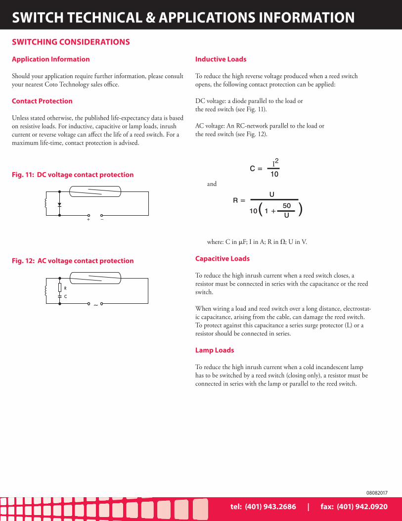
Contact Protection
Unless stated otherwise, the published life-expectancy data is based on resistive loads. For inductive, capacitive or lamp loads, inrush current or reverse voltage can affect the life of a reed switch. For a maximum life-time, contact protection is advised.
Inductive Loads
To reduce the high reverse voltage produced when a reed switch opens, the following contact protection can be applied:
DC voltage: a diode parallel to the load orthe reed switch (see Fig. 11).
AC voltage: An RC-network parallel to the load or the reed switch (see Fig. 12).
and
where: C in μF; I in A; R in Ω; U in V.
Capacitive Loads
To reduce the high inrush current when a reed switch closes, a resistor must be connected in series with the capacitance or the reed switch.
When wiring a load and reed switch over a long distance, electrostat-ic capacitance, arising from the cable, can damage the reed switch. To protect against this capacitance a series surge protector (L) or a resistor should be connected in series.
Lamp Loads
To reduce the high inrush current when a cold incandescent lamp has to be switched by a reed switch (closing only), a resistor must be connected in series with the lamp or parallel to the reed switch.
SWITCHING CONSIDERATIONS
C =10I2
R =U
10 1 +( 50U
)
Fig. 11: DC voltage contact protection
+ _
Fig. 12: AC voltage contact protection
~
R
C
tel: (401) 943.2686 | fax: (401) 942.0920
08082017
COTO TECHNOLOGY, INC.For most recent data visit www.cotorelay.com
REPRESENTATIVES & DISTRIBUTORS - WORLDWIDE
Coto maintains an active network of distributors and representatives across the globe. Wherever you are, you know that you can always find knowledgeable personnel who will be happy to help you find that perfect small signal switching solution.
COTO TECHNOLOGY, INC.For most recent data visit www.cotorelay.com
08082017