Embed Size (px)
Citation preview
ROMEO WP6 Page 1/82
RReemmoottee CCoollllaabboorraattiivvee RReeaall--TTiimmee MMuullttiimmeeddiiaa EExxppeerriieennccee oovveerr
tthhee FFuuttuurree IInntteerrnneett
RROOMMEEOO
Grant Agreement Number: 287896
D6.5
Second report on server, peer, user terminal, security and content registration modules development
Ref. Ares(2013)3156899 - 02/10/2013
ROMEO WP6 Page 2/82
Document description
Name of document Second report on server, peer, user terminal,
security and content registration modules
development
Abstract This document defines the progress of
development activities in the second year of the
project.
Document identifier D6.5
Document class Deliverable
Version 1.0
Author(s) H. Marques, H. Silva, E. Logota, J. Rodriguez
(IT)
K. Georgiev, E. Angelov (MMS)
Fernando Pascual (TID)
K. Birkos, A Likourgiotis, A Kordelas (UP),
M. Urban, M. Meier, P. tho Pesch (IRT)
X. Shi (Mulsys)
E. Ekmekcioglu, C.Kim, H. Lim (US)
O. Altunbaş, C. Özkan, E. Çimen Öztürk (TTA)
N. Tizon (VITEC)
D. Didier (TEC)
H.Weigold, J. Lauterjung (R&S)
G. O. Tanık (ARC)
QAT team P. tho Pesch (IRT), B. Demirtaş (ARCELIK), X.
Shi (MULSYS)
Date of creation 02-Aug-2013
Date of last modification 28-Sep-2013
Status Final
Destination European Commission
WP number WP6
Dissemination Level Public
Deliverable Nature Report
ROMEO WP6 Page 3/82
TABLE OF CONTENTS
TABLE OF CONTENTS ............................................................................................................. 3
LIST OF FIGURES...................................................................................................................... 5
LIST OF TABLES ....................................................................................................................... 7
1 INTRODUCTION ................................................................................................................. 8
1.1 Purpose of the document ............................................................................................ 8
1.2 Scope of the work ........................................................................................................ 8
1.3 Structure of the document ........................................................................................... 8
2 SERVER COMPONENTS ................................................................................................... 9
2.1 Content Generation ..................................................................................................... 9
2.1.1 Content Capturing ............................................................................................... 9
2.1.2 Visual Attention Modelling ................................................................................... 9
2.1.3 Media Encoding and TS Generation ................................................................. 10
2.2 P2P ............................................................................................................................ 19
2.2.1 Topology Builder/Multicast Tree Manager ........................................................ 19
2.2.2 P2P Transmitter ................................................................................................ 25
2.2.3 P2P Packetisation ............................................................................................. 26
2.3 Authentication, Registry and Security ....................................................................... 27
2.3.1 Description ........................................................................................................ 27
2.4 A/V Communication Overlay ..................................................................................... 30
2.4.1 Conference Controller ....................................................................................... 33
2.4.2 A/V Content Distributor ...................................................................................... 34
2.4.3 A/V Content Receiver ........................................................................................ 34
3 PEER COMPONENTS ...................................................................................................... 35
3.1 P2P ............................................................................................................................ 35
3.1.1 Topology Controller ........................................................................................... 35
3.1.2 Chunk Selection ................................................................................................ 36
3.1.3 P2P Transmitter/Receiver ................................................................................. 38
3.1.4 P2P Depacketisation ......................................................................................... 39
3.2 DVB Reception .......................................................................................................... 39
3.2.1 Fixed/Portable Terminals .................................................................................. 39
3.2.2 Mobile Terminals ............................................................................................... 41
3.3 Synchronisation ......................................................................................................... 42
3.3.1 Play-out Synchronisation................................................................................... 42
3.3.2 Collaborative Synchronisation ........................................................................... 44
3.4 A/V Communication Overlay ..................................................................................... 44
3.5 Video Decoding ......................................................................................................... 46
ROMEO WP6 Page 4/82
3.5.1 Video decoding for fixed and portable terminals ............................................... 46
3.5.2 Video decoding for the mobile terminal ............................................................. 47
3.5.3 Audio Decode and Rendering ........................................................................... 49
3.5.4 Audio Decoder ................................................................................................... 49
3.5.5 Renderer for Fixed Terminal ............................................................................. 51
3.5.6 Renderer Interface for Portable and Mobile Terminal ....................................... 51
3.5.7 Renderer for Portable Terminal ......................................................................... 52
3.5.8 Renderer for Mobile Terminal ........................................................................... 52
3.6 Video Rendering ........................................................................................................ 52
3.6.1 Video rendering for fixed terminal ..................................................................... 52
3.6.2 Video rendering for mobile terminal .................................................................. 54
3.7 A/V Adaptation and Network Monitor ........................................................................ 55
3.7.1 Audio/video adaptation decision block .............................................................. 55
3.7.2 Network Monitoring Subsystem ........................................................................ 56
3.8 User Interface and Control ........................................................................................ 59
3.8.1 DVB Reception UI ............................................................................................. 59
3.8.2 Renderer Module UI .......................................................................................... 60
3.8.3 Overlay Module UI ............................................................................................. 60
3.8.4 User Generated Content UI............................................................................... 61
4 NETWORK RELATED COMPONENTS ........................................................................... 62
4.1 Mobility ...................................................................................................................... 62
4.1.1 Media Independent Handover (MIH) ................................................................. 62
4.1.2 Media Aware Proxy ........................................................................................... 64
4.1.3 Proxy Mobile IP ................................................................................................. 68
4.2 Virtualisation .............................................................................................................. 70
4.2.1 Description and current status .......................................................................... 70
4.2.2 Future work ....................................................................................................... 71
4.3 Internet Resource and Admission Control System ................................................... 71
4.3.1 Resource and Admission Manager (RAM) ........................................................ 72
4.3.2 Resource Controller (RC) .................................................................................. 74
5 CONCLUSION .................................................................................................................. 76
6 REFERENCES .................................................................................................................. 77
APPENDIX A: GLOSSARY OF ABBREVIATIONS ................................................................. 78
ROMEO WP6 Page 5/82
LIST OF FIGURES
Figure 1 - Overview of the Visual Attention Modelling module ................................................................... 9
Figure 2 - Video Encoder architecture deployed in ROMEO server, to be used in the demonstrator ...... 10
Figure 3 - Brief overview of the SI-based encoder structureAudio Encoding ........................................... 11
Figure 4 - General structure of the Transport Streams used in ROMEO.................................................. 13
Figure 5 - Stream Splitter GUI .................................................................................................................. 14
Figure 6 - User interface of the Transport Stream generation tool ........................................................... 17
Figure 7 - User interface of the H.264 analyser tool ................................................................................. 18
Figure 8 - Example of syntax of streams with corrected PTS ................................................................... 19
Figure 9 - The TopologyChanges class and its functions ......................................................................... 20
Figure 10 - The Peer class and its functions ............................................................................................ 21
Figure 11 - The IPRange class and its functions ...................................................................................... 22
Figure 12 - The BWServer class and its functions ................................................................................... 22
Figure 13 - The BWClientHandler class and its functions ........................................................................ 22
Figure 14 - The BWClientHandler class and its functions ........................................................................ 23
Figure 15 - The ClientList class and its functions ..................................................................................... 23
Figure 16 - The HTTP class and its functions .......................................................................................... 23
Figure 17 - The Node class and its functions ........................................................................................... 24
Figure 18 - The NMSReport class and its functions ................................................................................. 24
Figure 19 - The JsonServer class and its functions ................................................................................. 25
Figure 20 - A/V Communication Overlay overall system description (Green - stream, Red - control data) ......................................................................................................................................................... 31
Figure 21 - Media Distribution and Distribution Control Mechanism of Red5 ........................................... 32
Figure 22 - Modification under Conference Controller.............................................................................. 32
Figure 23 - Added functions & attributes & connections on Server for delay ........................................... 33
Figure 24 - Design for setDelay and getDelay functions .......................................................................... 34
Figure 25 - The TopologyController class and its functions ..................................................................... 35
Figure 26 - The Parent class and its functions ......................................................................................... 35
Figure 27 - The JsonServer class and its functions ................................................................................. 36
Figure 28 - DVB Reception Block Diagram .............................................................................................. 41
Figure 29 - Overview process of DVB reception, decoding and rendering ............................................... 42
ROMEO WP6 Page 6/82
Figure 30 - Play-Out Synchronisation Blocks ........................................................................................... 44
Figure 31 - Message communication between OpenMeetings server and Client .................................... 44
Figure 32 - Gstreamer usage for audio and video transfer ....................................................................... 45
Figure 33 - Video decoder for fixed and portable terminals ...................................................................... 46
Figure 34 - Overview diagram of Ducati subsystem used to perform video decoding .............................. 47
Figure 35 - Functional blocks for video decoding process ....................................................................... 48
Figure 36 - Incoming audio packet structure ............................................................................................ 49
Figure 37 - Decoded output audio data structure ..................................................................................... 50
Figure 38 - Description of the structure of aacDecodedFormat Information within the decoded output data ......................................................................................................................................................... 51
Figure 39 - MVD4 multi-view rendering scheme ...................................................................................... 53
Figure 40 - GPU core architecture ........................................................................................................... 54
Figure 41 - MVD2_3 scheme ................................................................................................................... 56
Figure 42 - The Specs class and its functions .......................................................................................... 57
Figure 43 - The PacketCapture class and its functions ............................................................................ 58
Figure 44 - The BWClient class and its functions ..................................................................................... 58
Figure 45 - The NMSReporting class and its functions ............................................................................ 59
Figure 46 - DVB Reception UI .................................................................................................................. 60
Figure 47 - Renderer Module UI .............................................................................................................. 60
Figure 48 - Overlay Module UI ................................................................................................................. 61
Figure 49. Cross-layer QoS control architecture. ..................................................................................... 72
Figure 50 - Illustration of the IRACS operations ....................................................................................... 73
ROMEO WP6 Page 7/82
LIST OF TABLES
Table 1 - Syntax of the “Additional Content URL Descriptor” ................................................................... 15
Table 2 - Values for additonal_content_id ................................................................................................ 15
Table 3 - TC module messages ............................................................................................................... 36
Table 4 - Messages from CS to other modules ........................................................................................ 38
Table 5 - Performance for DVB-Reception ............................................................................................... 42
Table 6 - A/V Overlay Performance Test Results .................................................................................... 45
Table 7 - Messages from NMS to other modules ..................................................................................... 59
ROMEO WP6 Page 8/82
1 INTRODUCTION
1.1 Purpose of the document
This document aims to provide the development status of the ROMEO project for both server
and peer components. While this document is used to check whether the development of
components is aligned with the timeline presented in D6.3, it also provides a good summary
on the development efforts for the whole ROMEO system.
1.2 Scope of the work
The scope of this document is to describe the development made so far for each module. The
detailed description of the developed components, APIs to be used by the developed
components as well as the common APIs to be shared by all components are provided in this
document.
1.3 Structure of the document
The document has three main sections:
Server Components
Peer Components
Network Infrastructure Components
Each section includes detailed information on the module development status.
ROMEO WP6 Page 9/82
2 SERVER COMPONENTS
2.1 Content Generation
2.1.1 Content Capturing
Three sets of raw audio and video contents corresponding to three capturing sessions have
been delivered between the 8th and the 16th month of the project.
At the end of the shooting sessions, two kinds of content were available:
Raw content generated from the professional equipments for the next processing
stages
Raw content generated from the user terminals (UGC - User Generated Content)
Before delivering this content, the raw data has been post-processed and tested/validated
thanks to the first versions of the rendering modules. The acquisition and post-processing
modules are specified in D3.1. After post-processing, the audio and video contents are
delivered in raw data format (uncompressed).
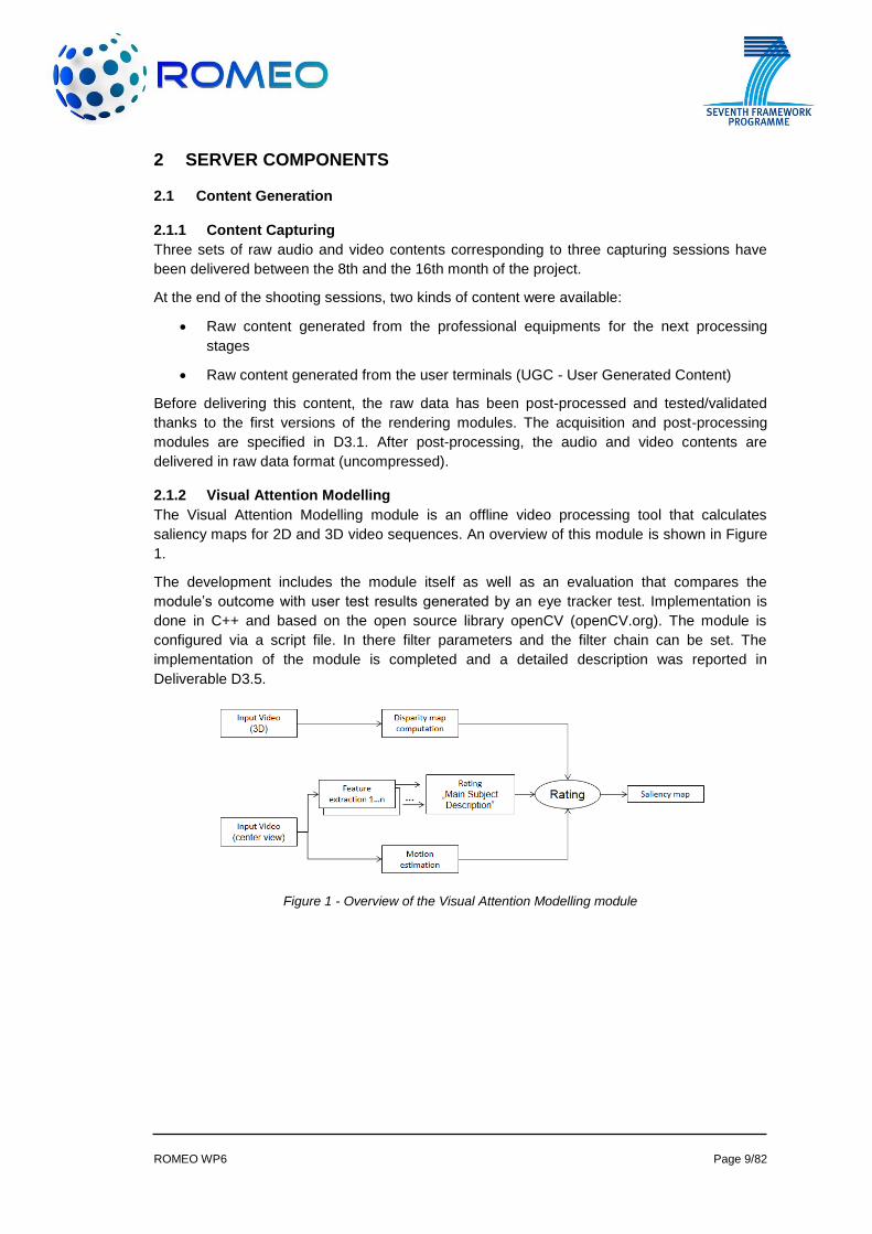
2.1.2 Visual Attention Modelling
The Visual Attention Modelling module is an offline video processing tool that calculates
saliency maps for 2D and 3D video sequences. An overview of this module is shown in Figure
1.
The development includes the module itself as well as an evaluation that compares the
module’s outcome with user test results generated by an eye tracker test. Implementation is
done in C++ and based on the open source library openCV (openCV.org). The module is
configured via a script file. In there filter parameters and the filter chain can be set. The
implementation of the module is completed and a detailed description was reported in
Deliverable D3.5.
Figure 1 - Overview of the Visual Attention Modelling module
ROMEO WP6 Page 10/82
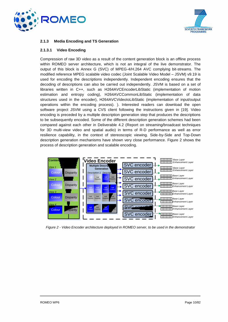
2.1.3 Media Encoding and TS Generation
2.1.3.1 Video Encoding
Compression of raw 3D video as a result of the content generation block is an offline process
within ROMEO server architecture, which is not an integral of the live demonstrator. The
output of this block is Annex G (SVC) of MPEG-4/H.264 AVC complying bit-streams. The
modified reference MPEG scalable video codec (Joint Scalable Video Model – JSVM) v9.19 is
used for encoding the descriptions independently. Independent encoding ensures that the
decoding of descriptions can also be carried out independently. JSVM is based on a set of
libraries written in C++, such as H264AVCEncoderLibStatic (implementation of motion
estimation and entropy coding), H264AVCCommonLibStatic (implementation of data
structures used in the encoder), H264AVCVideoIoLibStatic (implementation of input/output
operations within the encoding process). ). Interested readers can download the open
software project JSVM using a CVS client following the instructions given in [19]. Video
encoding is preceded by a multiple description generation step that produces the descriptions
to be subsequently encoded. Some of the different description generation schemes had been
compared against each other in Deliverable 4.2 (Report on streaming/broadcast techniques
for 3D multi-view video and spatial audio) in terms of R-D performance as well as error
resilience capability, in the context of stereoscopic viewing. Side-by-Side and Top-Down
description generation mechanisms have shown very close performance. Figure 2 shows the
process of description generation and scalable encoding.
Figure 2 - Video Encoder architecture deployed in ROMEO server, to be used in the demonstrator
SVC encoderContent GenerationContent Generation
Colour
Colour
Colour
Colour
Disparity
Disparity
Disparity
Disparity
View 1View 1
View 2View 2
View 3View 3
View 4View 4
Video EncoderMultiple Description
Generation
Multiple Description
Generation
Half
Colour
Half
Disparity
Half
Colour
Half
Disparity
Half
Colour
Half
Disparity
Half
Colour
Half
Disparity
Half
Colour
Half
Colour
Half
Colour
Half
Colour
Half
Disparity
Half
Disparity
Half
Disparity
Half
Disparity
Description 1Description 1
Description 2Description 2
Base LayerBase Layer
Enhancement LayerEnhancement Layer
SVC encoder
SVC encoder
SVC encoder
SVC encoder
SVC encoder
SVC encoder
SVC encoder
Base LayerBase Layer
Enhancement LayerEnhancement Layer
Base LayerBase Layer
Enhancement LayerEnhancement Layer
Base LayerBase Layer
Enhancement LayerEnhancement Layer
Base LayerBase Layer
Enhancement LayerEnhancement Layer
Base LayerBase Layer
Enhancement LayerEnhancement Layer
Base LayerBase Layer
Enhancement LayerEnhancement Layer
Base LayerBase Layer
Enhancement LayerEnhancement Layer
ROMEO WP6 Page 11/82
Sixteen descriptions in total are generated, one of which (base layer of the first description of
the stereoscopic pair – views 2 & 3) is sent through DVB after encapsulating into MPEG-2 TS
(described in Figure 2).
The reference SVC encoder has been modified to read an additional set of configuration
parameters as well as a gray-scale map, which represents the macroblock-based saliency
information (based on the low-level features within the scope of the visual attention research
carried out in WP3) for regionally adaptive bit-rate assignment. The additional configuration
parameters include the Quantisation Parameter (QP) offset to be applied on each defined
saliency region. More details are provided in Deliverable 4.3 (Report on the developed audio
and video codecs).
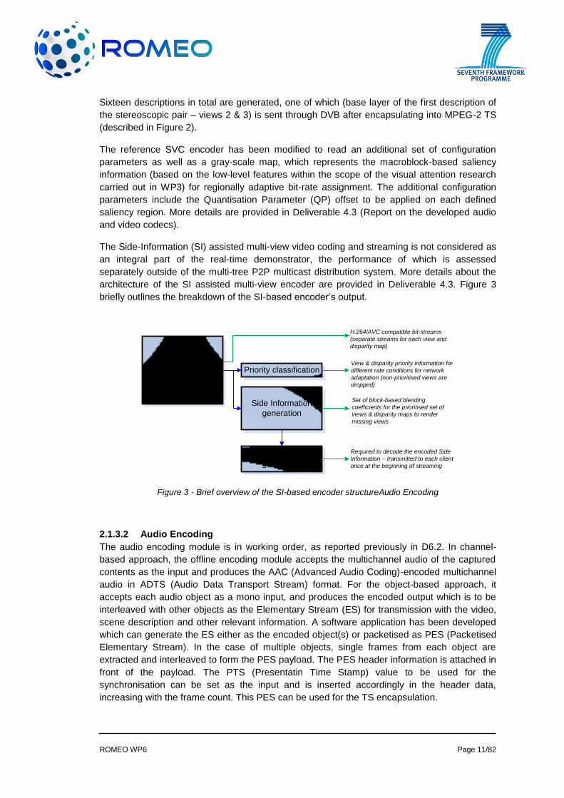
The Side-Information (SI) assisted multi-view video coding and streaming is not considered as
an integral part of the real-time demonstrator, the performance of which is assessed
separately outside of the multi-tree P2P multicast distribution system. More details about the
architecture of the SI assisted multi-view encoder are provided in Deliverable 4.3. Figure 3
briefly outlines the breakdown of the SI-based encoder’s output.
Figure 3 - Brief overview of the SI-based encoder structureAudio Encoding
2.1.3.2 Audio Encoding
The audio encoding module is in working order, as reported previously in D6.2. In channel-
based approach, the offline encoding module accepts the multichannel audio of the captured
contents as the input and produces the AAC (Advanced Audio Coding)-encoded multichannel
audio in ADTS (Audio Data Transport Stream) format. For the object-based approach, it
accepts each audio object as a mono input, and produces the encoded output which is to be
interleaved with other objects as the Elementary Stream (ES) for transmission with the video,
scene description and other relevant information. A software application has been developed
which can generate the ES either as the encoded object(s) or packetised as PES (Packetised
Elementary Stream). In the case of multiple objects, single frames from each object are
extracted and interleaved to form the PES payload. The PES header information is attached in
front of the payload. The PTS (Presentatin Time Stamp) value to be used for the
synchronisation can be set as the input and is inserted accordingly in the header data,
increasing with the frame count. This PES can be used for the TS encapsulation.
Multi-view plus
disparity map
encoder
Side Information
generation
Priority classification
Codebook
generation
H.264/AVC compatible bit-streams
(separate streams for each view and
disparity map)
H.264/AVC compatible bit-streams
(separate streams for each view and
disparity map)
View & disparity priority information for
different rate conditions for network
adaptation (non-prioritised views are
dropped)
View & disparity priority information for
different rate conditions for network
adaptation (non-prioritised views are
dropped)
Set of block-based blending
coefficients for the prioritised set of
views & disparity maps to render
missing views
Set of block-based blending
coefficients for the prioritised set of
views & disparity maps to render
missing views
Required to decode the encoded Side
Information – transmitted to each client
once at the beginning of streaming
Required to decode the encoded Side
Information – transmitted to each client
once at the beginning of streaming
ROMEO WP6 Page 12/82
On the other hand, a GUI-based real-time audio capturing/encoding application has been
developed. Instead of an audio file, multichannel audio stream through a microphone array is
used as the input. The frames are encoded in real-time and can be streamed via TCP or
stored as a 5.1-channel AAC file. Further development has also been made in the Analysis-
by-Synthesis (AbS) coding technique, separately from the implementation of the practical
encoding module towards the integration and demonstration. The details of its operation are
described in D4.3. It is a new SAC (Spatial Audio Coding) technique based on the principle of
closed-loop system. An algorithm for selecting sub-optimal signals and parameters through
iterations has also been integrated, which offers complexity scalability, providing a trade-off
between the complexity of the encoder and the quality of the reconstructed audio signals. The
experimental results, for encoding five-channel audio signals at bit-rates ranging from 40 to 96
kb/s per audio channel using two reasonable complexity levels of the encoder, demonstrate
that significant improvement of performances is achieved compared with the conventional
open-loop techniques. At the lowest complexity level, the encoder is capable of working in a
real-time implementation, although at a higher complexity level for enhanced quality, the
computation time increases approximately 72 times.
2.1.3.3 TS Generation
2.1.3.3.1 Structure of the MPEG2 Transport Stream in ROMEO
The generation of MPEG2 Transport Streams (TS) is based on the scheme of camera views,
video descriptions and layers as described in Deliverable D4.1 [7]. For the purpose of the
ROMEO project, all views, descriptions and layers plus all audio signals of a certain test
sequence are combined into one comprehensive TS.
One part of this TS is broadcast over the DVB transmitter, the other part can be accessed by
each peer via the servers which form part of the ROMEO network structure. The
comprehensive TS contains all necessary tables of program specific information and service
information (PSI/SI) that enable a DVB receiver to identify and then decode the required video
and audio streams.
The TS generation takes the Elementary Streams (ES) as input. These ES were encoded by
ROMEO partner University of Surrey and each contains two layers of one of several view –
description combinations.
The PSI/SI data are organised in those DVB-standard-compliant tables which are mandatory
for a TS that is to be distributed over a DVB network [8]. These tables are
PAT Program Association Table
NIT Network Information Table
SDT Service Description Table
EIT Event Information Table
TDT Time and Date Table
PMT Program Map Table
RST Running Status Table
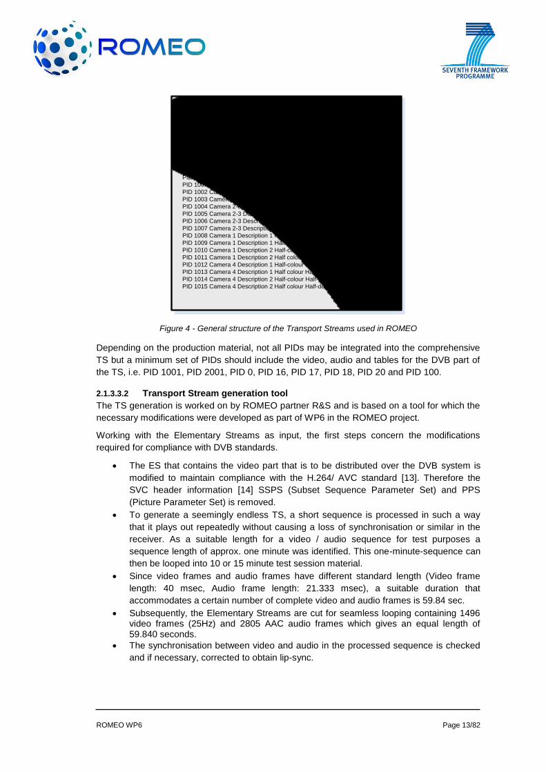
For all test sequences that are used in ROMEO, the various parts of the TS are ordered into
the same scheme of Packet IDentifiers (PID) as depicted in Figure 4.
ROMEO WP6 Page 13/82
PID 1001 Camera 2-3 Half-colour High quality Base layer
PID 2001 Audio (MPEG2 Stereo)
PID 2002 Audio (AAC/ 5.1)
PID 2003 Audio (Scene Description)
PID 2004 Audio (Object-based)
PID 0 PAT
PID 16 NIT
PID 17 SDT
PID 18 EIT
PID 20 TDT
PID 100 PMT for service containing Camera 2-3 DVB Half-colour
PID 1002 Camera 2-3 Description 2 Half-colour Base layer
PID 1003 Camera 2-3 Description 2 Half-colour Enhancement layer
PID 1004 Camera 2-3 Description 1 Half-depth Base layer
PID 1005 Camera 2-3 Description 1 Half-depth Enhancement layer
PID 1006 Camera 2-3 Description 2 Half-depth Base layer
PID 1007 Camera 2-3 Description 2 Half-depth Enhancement layer
PID 1008 Camera 1 Description 1 Half-colour Half-depth Base layer
PID 1009 Camera 1 Description 1 Half colour Half-depth Enhancement layer
PID 1010 Camera 1 Description 2 Half-colour Half-depth Base layer
PID 1011 Camera 1 Description 2 Half colour Half-depth Enhancement layer
PID 1012 Camera 4 Description 1 Half-colour Half-depth Base layer
PID 1013 Camera 4 Description 1 Half colour Half-depth Enhancement layer
PID 1014 Camera 4 Description 2 Half-colour Half-depth Base layer
PID 1015 Camera 4 Description 2 Half colour Half-depth Enhancement layer
Figure 4 - General structure of the Transport Streams used in ROMEO
Depending on the production material, not all PIDs may be integrated into the comprehensive
TS but a minimum set of PIDs should include the video, audio and tables for the DVB part of
the TS, i.e. PID 1001, PID 2001, PID 0, PID 16, PID 17, PID 18, PID 20 and PID 100.
2.1.3.3.2 Transport Stream generation tool
The TS generation is worked on by ROMEO partner R&S and is based on a tool for which the
necessary modifications were developed as part of WP6 in the ROMEO project.
Working with the Elementary Streams as input, the first steps concern the modifications
required for compliance with DVB standards.
The ES that contains the video part that is to be distributed over the DVB system is
modified to maintain compliance with the H.264/ AVC standard [13]. Therefore the
SVC header information [14] SSPS (Subset Sequence Parameter Set) and PPS
(Picture Parameter Set) is removed.
To generate a seemingly endless TS, a short sequence is processed in such a way
that it plays out repeatedly without causing a loss of synchronisation or similar in the
receiver. As a suitable length for a video / audio sequence for test purposes a
sequence length of approx. one minute was identified. This one-minute-sequence can
then be looped into 10 or 15 minute test session material.
Since video frames and audio frames have different standard length (Video frame
length: 40 msec, Audio frame length: 21.333 msec), a suitable duration that
accommodates a certain number of complete video and audio frames is 59.84 sec.
Subsequently, the Elementary Streams are cut for seamless looping containing 1496 video frames (25Hz) and 2805 AAC audio frames which gives an equal length of 59.840 seconds.
The synchronisation between video and audio in the processed sequence is checked
and if necessary, corrected to obtain lip-sync.
ROMEO WP6 Page 14/82
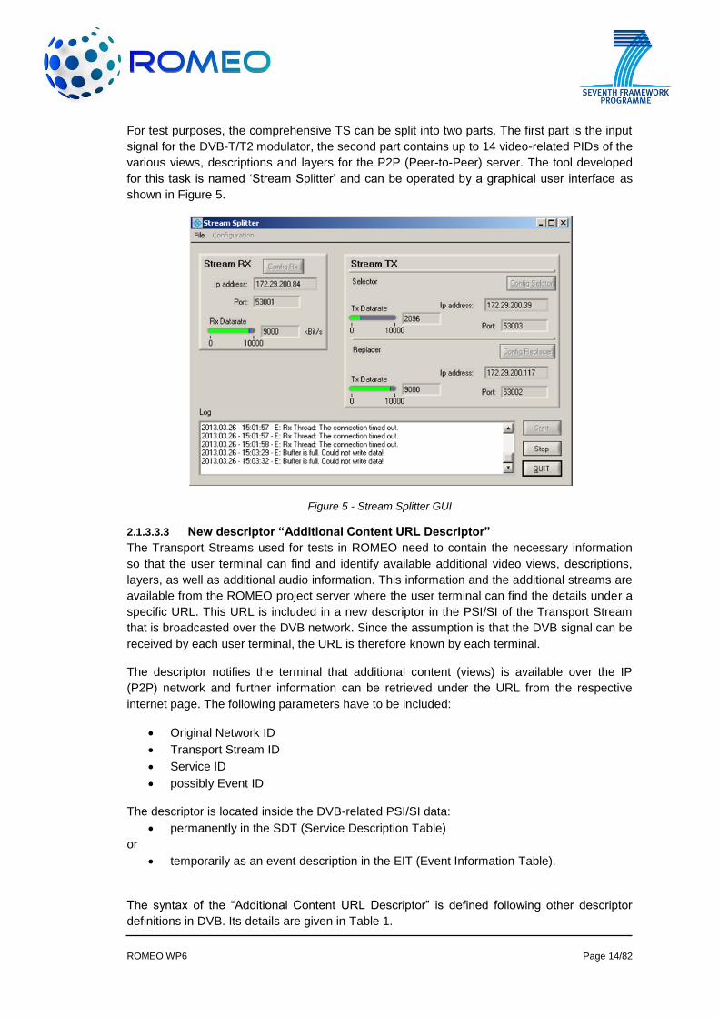
For test purposes, the comprehensive TS can be split into two parts. The first part is the input
signal for the DVB-T/T2 modulator, the second part contains up to 14 video-related PIDs of the
various views, descriptions and layers for the P2P (Peer-to-Peer) server. The tool developed
for this task is named ‘Stream Splitter’ and can be operated by a graphical user interface as
shown in Figure 5.
Figure 5 - Stream Splitter GUI
2.1.3.3.3 New descriptor “Additional Content URL Descriptor”
The Transport Streams used for tests in ROMEO need to contain the necessary information
so that the user terminal can find and identify available additional video views, descriptions,
layers, as well as additional audio information. This information and the additional streams are
available from the ROMEO project server where the user terminal can find the details under a
specific URL. This URL is included in a new descriptor in the PSI/SI of the Transport Stream
that is broadcasted over the DVB network. Since the assumption is that the DVB signal can be
received by each user terminal, the URL is therefore known by each terminal.
The descriptor notifies the terminal that additional content (views) is available over the IP
(P2P) network and further information can be retrieved under the URL from the respective
internet page. The following parameters have to be included:
Original Network ID
Transport Stream ID
Service ID
possibly Event ID
The descriptor is located inside the DVB-related PSI/SI data:
permanently in the SDT (Service Description Table)
or
temporarily as an event description in the EIT (Event Information Table).
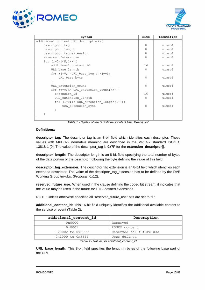
The syntax of the “Additional Content URL Descriptor” is defined following other descriptor
definitions in DVB. Its details are given in Table 1.
ROMEO WP6 Page 15/82
Syntax Bits Identifier
additional_content_URL_descriptor(){
descriptor_tag 8 uimsbf
descriptor_length 8 uimsbf
descriptor_tag_extension 8 uimsbf
reserved_future_use 8 uimsbf
for (i=0;i<N;i++){
additional_content_id 16 uimsbf
URL_base_length 8 uimsbf
for (j=0;j<URL_base_length;j++){
URL_base_byte 8 uimsbf
}
URL_extension_count 8 uimsbf
for (k=0;k< URL_extension_count;k++){
extension_id 16 uimsbf
URL_extension_length 8 uimsbf
for (l=0;l< URL_extension_length;l++){
URL_extension_byte 8 uimsbf
}
}
}
Table 1 - Syntax of the “Additional Content URL Descriptor”
Definitions:
descriptor_tag: The descriptor tag is an 8-bit field which identifies each descriptor. Those
values with MPEG-2 normative meaning are described in the MPEG2 standard ISO/IEC
13818-1 [9]. The value of the descriptor_tag is 0x7F for the extension_descriptor().
descriptor_length: The descriptor length is an 8-bit field specifying the total number of bytes
of the data portion of the descriptor following the byte defining the value of this field.
descriptor_tag_extension: The descriptor tag extension is an 8-bit field which identifies each
extended descriptor. The value of the descriptor_tag_extension has to be defined by the DVB
Working Group tm-gbs. (Proposal: 0x12).
reserved_future_use: When used in the clause defining the coded bit stream, it indicates that
the value may be used in the future for ETSI defined extensions.
NOTE: Unless otherwise specified all "reserved_future_use" bits are set to "1".
additional_content_id: This 16-bit field uniquely identifies the additional available content to
the service or event (Table 2).
additional_content_id Description
0x0000 Reserved
0x0001 ROMEO content
0x0002 to 0x0FFF Reserved for future use
0x1000 to 0xFFFF User defined
Table 2 - Values for additonal_content_id
URL_base_length: This 8-bit field specifies the length in bytes of the following base part of
the URL.
ROMEO WP6 Page 16/82
URL_base_byte: This is an 8-bit field. These bytes form the first part of a HTTP URL
conforming to HTTP 1.0 (see RFC 1945 [10]), or the first part of an HTTPS URL conforming to
RFC 2818 [11] or the first part of another URL conforming to RFC 3986 [12].
All bytes interpreted as text shall be encoded as UTF8, but shall not include the null character,
e.g. “www.ROMEO.Service-Guide.tv”.
URL_extension_count: This 8-bit field indicates the number of URL extensions conveyed by
this descriptor.
URL_extension_id: This 8-bit field identifies a purpose (e.g. ROMEO service number) of the
URL_extension.
URL_extension_length: This 8-bit field indicates the number of bytes in the extension part of
the URL.
URL_extension_byte: These bytes form the extension part of an HTTP URL conforming to
HTTP 1.0 (see RFC 1945 [10]), or the extension part of an HTTPS URL conforming to RFC
2818 [11] or otherwise a URL whose scheme is supported by a registered interaction channel
transport service provider implementation.
All bytes interpreted as text shall be encoded as UTF8, but shall not include the null character.
URLs are formed by concatenating the URL extension with the preceding URL base. The URL
so formed either identifies a file system directory or a specific XML file, e.g. “/romeo_esg.xml”.
The Classes (modules) that generate the DVB additional_content_URL_descriptor for the
ROMEO project were integrated with the existing version of the DVB service information
generation module in the TS generation tool.
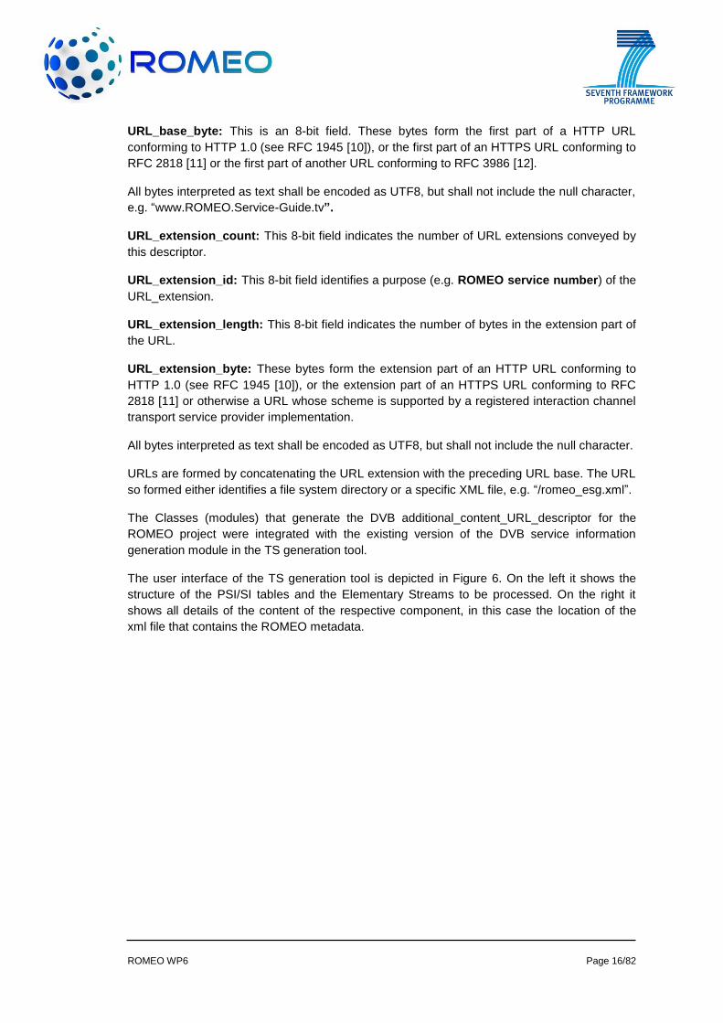
The user interface of the TS generation tool is depicted in Figure 6. On the left it shows the
structure of the PSI/SI tables and the Elementary Streams to be processed. On the right it
shows all details of the content of the respective component, in this case the location of the
xml file that contains the ROMEO metadata.
ROMEO WP6 Page 17/82
Figure 6 - User interface of the Transport Stream generation tool
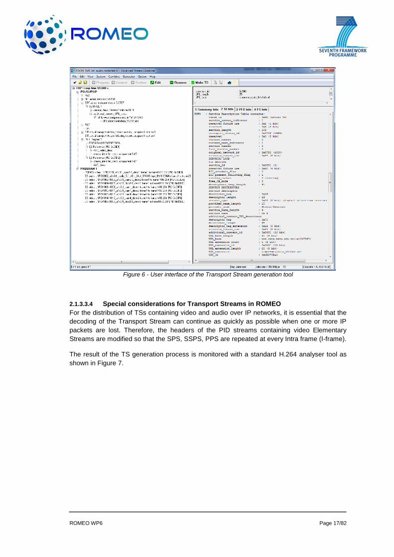
2.1.3.3.4 Special considerations for Transport Streams in ROMEO
For the distribution of TSs containing video and audio over IP networks, it is essential that the
decoding of the Transport Stream can continue as quickly as possible when one or more IP
packets are lost. Therefore, the headers of the PID streams containing video Elementary
Streams are modified so that the SPS, SSPS, PPS are repeated at every Intra frame (I-frame).
The result of the TS generation process is monitored with a standard H.264 analyser tool as
shown in Figure 7.
ROMEO WP6 Page 18/82
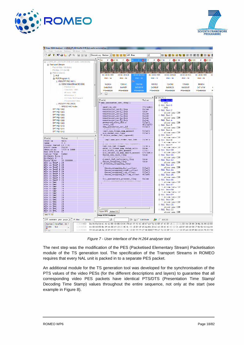
Figure 7 - User interface of the H.264 analyser tool
The next step was the modification of the PES (Packetised Elementary Stream) Packetisation
module of the TS generation tool. The specification of the Transport Streams in ROMEO
requires that every NAL unit is packed in to a separate PES packet.
An additional module for the TS generation tool was developed for the synchronisation of the
PTS values of the video PESs (for the different descriptions and layers) to guarantee that all
corresponding video PES packets have identical PTS/DTS (Presentation Time Stamp/
Decoding Time Stamp) values throughout the entire sequence, not only at the start (see
example in Figure 8).
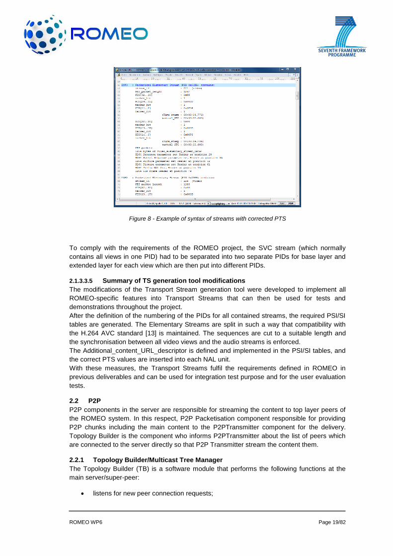
ROMEO WP6 Page 19/82
Figure 8 - Example of syntax of streams with corrected PTS
To comply with the requirements of the ROMEO project, the SVC stream (which normally
contains all views in one PID) had to be separated into two separate PIDs for base layer and
extended layer for each view which are then put into different PIDs.
2.1.3.3.5 Summary of TS generation tool modifications
The modifications of the Transport Stream generation tool were developed to implement all
ROMEO-specific features into Transport Streams that can then be used for tests and
demonstrations throughout the project.
After the definition of the numbering of the PIDs for all contained streams, the required PSI/SI
tables are generated. The Elementary Streams are split in such a way that compatibility with
the H.264 AVC standard [13] is maintained. The sequences are cut to a suitable length and
the synchronisation between all video views and the audio streams is enforced.
The Additional_content_URL_descriptor is defined and implemented in the PSI/SI tables, and
the correct PTS values are inserted into each NAL unit.
With these measures, the Transport Streams fulfil the requirements defined in ROMEO in
previous deliverables and can be used for integration test purpose and for the user evaluation
tests.
2.2 P2P
P2P components in the server are responsible for streaming the content to top layer peers of
the ROMEO system. In this respect, P2P Packetisation component responsible for providing
P2P chunks including the main content to the P2PTransmitter component for the delivery.
Topology Builder is the component who informs P2PTransmitter about the list of peers which
are connected to the server directly so that P2P Transmitter stream the content them.
2.2.1 Topology Builder/Multicast Tree Manager
The Topology Builder (TB) is a software module that performs the following functions at the
main server/super-peer:
listens for new peer connection requests;
ROMEO WP6 Page 20/82
acts as an authentication proxy (authenticator) for user authentication with the main
server;
creates multiple P2P application-level multicast trees for content distribution;
computes peer insertion on the P2P trees;
When a peer is redirected to a super-peer, it is the responsibility of the TB to compute the peer
position in the P2P multicast tree at access network level. The steps in the computation are: (i)
to group peers according to the requested content; (ii) group peers according to their common
edge router - geographical aggregation and; (iii) sort peers by evaluation, a metric explained in
ROMEO deliverable D5.1 [1].
The Multicast Tree Manager (MTM) is intrinsically related with the TB operations and has the
following functions:
It collects/aggregates network monitoring data (percentage of packet loss, average
delay, jitter and available bandwidth), from all connected peers, providing the TB with
updated peer’s network conditions;
It allows peers to perform bandwidth tests with the server/super-peer.
Next section describes the most relevant classes used by the TB and MTM to perform their
operations.
2.2.1.1 Provided Classes
The TB and MTM software modules are constituted by the following classes:
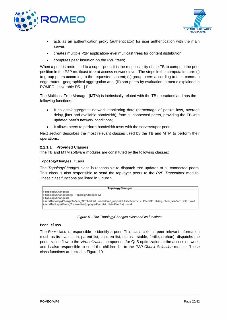
TopologyChanges class
The TopologyChanges class is responsible to dispatch tree updates to all connected peers.
This class is also responsible to send the top-layer peers to the P2P Transmitter module.
These class functions are listed in Figure 9.
Figure 9 - The TopologyChanges class and its functions
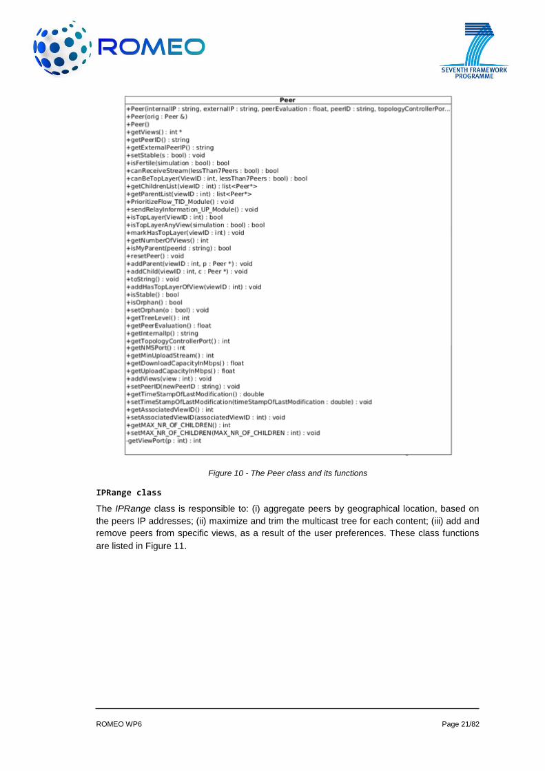
Peer class
The Peer class is responsible to identify a peer. This class collects peer relevant information
(such as its evaluation, parent list, children list, status - stable, fertile, orphan), dispatchs the
prioritization flow to the Virrtualization component, for QoS optimization at the access network,
and is also responsible to send the children list to the P2P Chunk Selection module. These
class functions are listed in Figure 10.
ROMEO WP6 Page 21/82
Figure 10 - The Peer class and its functions
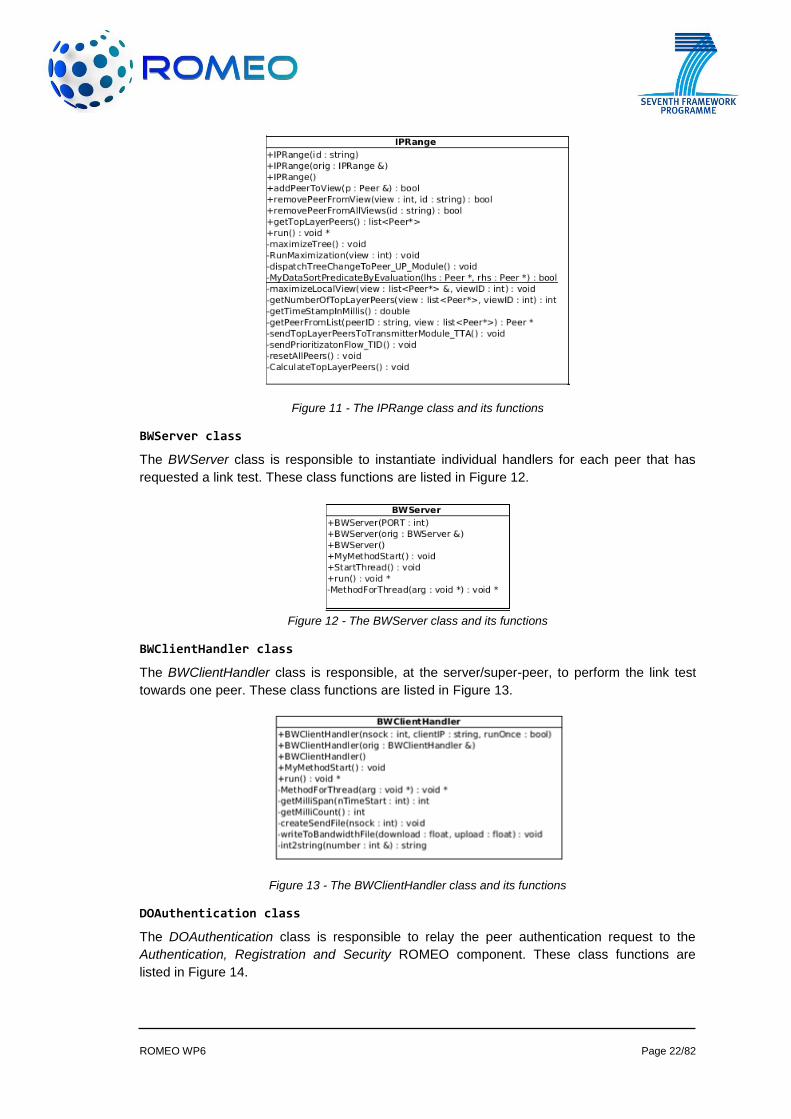
IPRange class
The IPRange class is responsible to: (i) aggregate peers by geographical location, based on
the peers IP addresses; (ii) maximize and trim the multicast tree for each content; (iii) add and
remove peers from specific views, as a result of the user preferences. These class functions
are listed in Figure 11.
ROMEO WP6 Page 22/82
Figure 11 - The IPRange class and its functions
BWServer class
The BWServer class is responsible to instantiate individual handlers for each peer that has
requested a link test. These class functions are listed in Figure 12.
Figure 12 - The BWServer class and its functions
BWClientHandler class
The BWClientHandler class is responsible, at the server/super-peer, to perform the link test
towards one peer. These class functions are listed in Figure 13.
Figure 13 - The BWClientHandler class and its functions
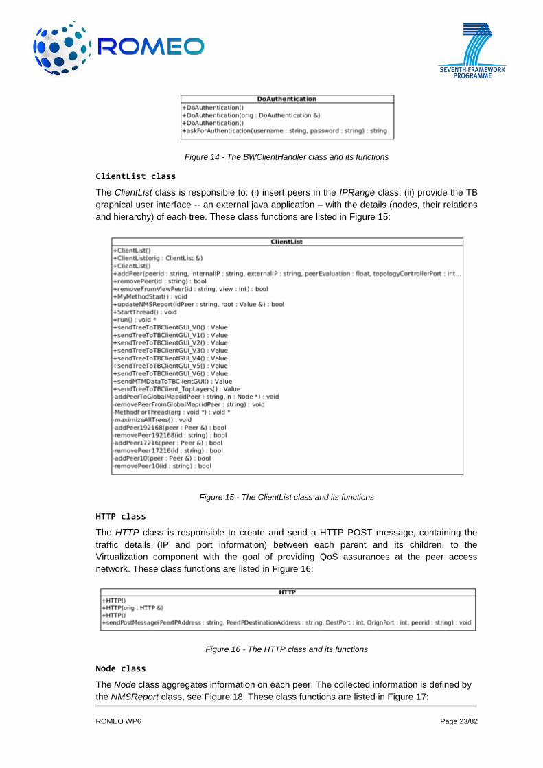
DOAuthentication class
The DOAuthentication class is responsible to relay the peer authentication request to the
Authentication, Registration and Security ROMEO component. These class functions are
listed in Figure 14.
ROMEO WP6 Page 23/82
Figure 14 - The BWClientHandler class and its functions
ClientList class
The ClientList class is responsible to: (i) insert peers in the IPRange class; (ii) provide the TB
graphical user interface -- an external java application – with the details (nodes, their relations
and hierarchy) of each tree. These class functions are listed in Figure 15:
Figure 15 - The ClientList class and its functions
HTTP class
The HTTP class is responsible to create and send a HTTP POST message, containing the
traffic details (IP and port information) between each parent and its children, to the
Virtualization component with the goal of providing QoS assurances at the peer access
network. These class functions are listed in Figure 16:
Figure 16 - The HTTP class and its functions
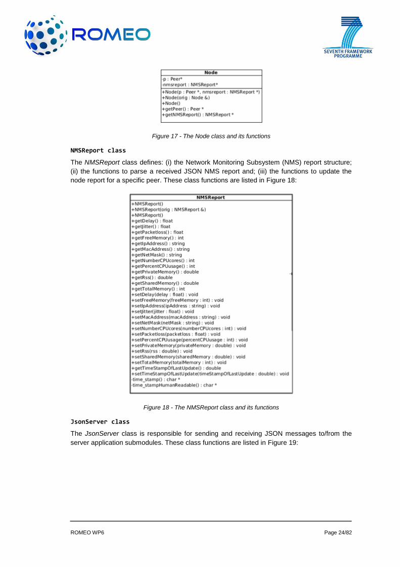
Node class
The Node class aggregates information on each peer. The collected information is defined by
the NMSReport class, see Figure 18. These class functions are listed in Figure 17:
ROMEO WP6 Page 24/82
Figure 17 - The Node class and its functions
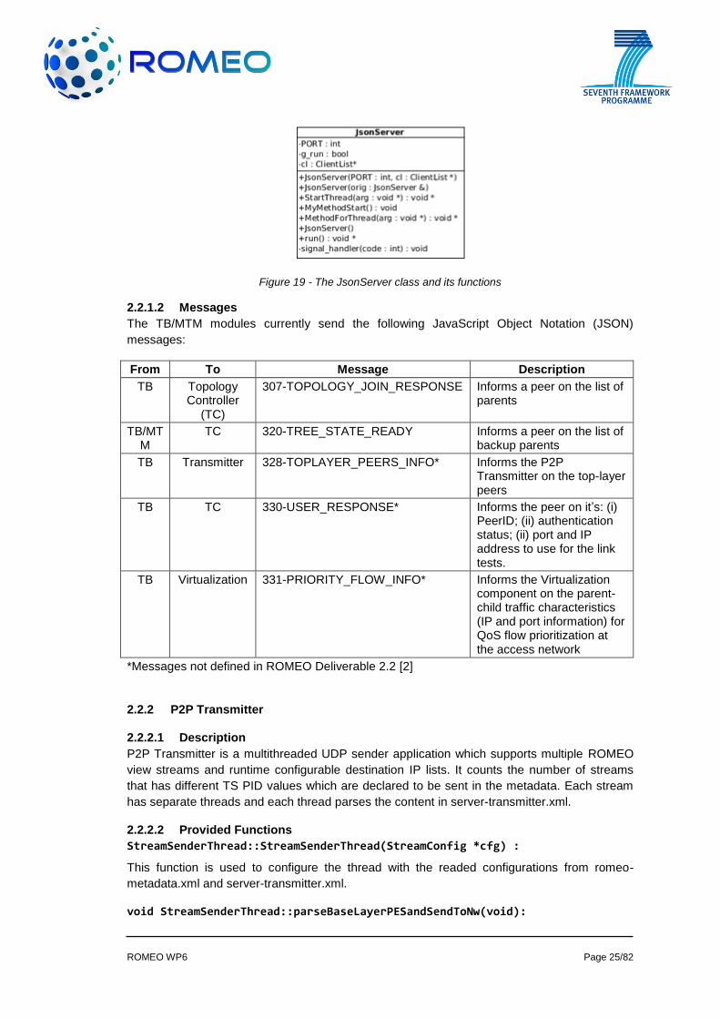
NMSReport class
The NMSReport class defines: (i) the Network Monitoring Subsystem (NMS) report structure;
(ii) the functions to parse a received JSON NMS report and; (iii) the functions to update the
node report for a specific peer. These class functions are listed in Figure 18:
Figure 18 - The NMSReport class and its functions
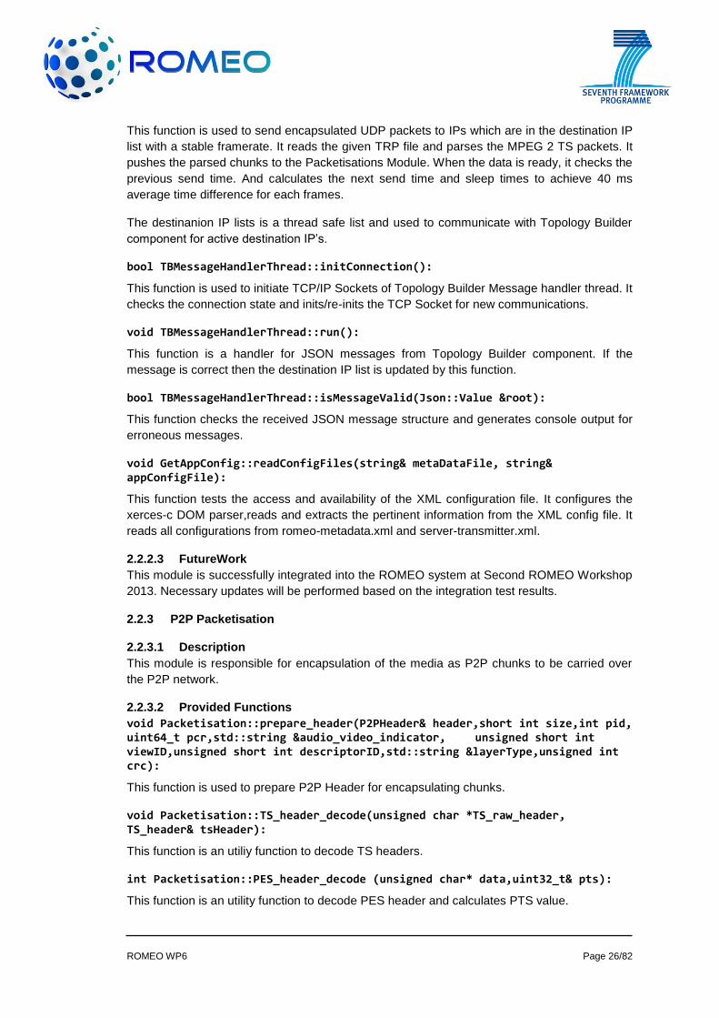
JsonServer class
The JsonServer class is responsible for sending and receiving JSON messages to/from the
server application submodules. These class functions are listed in Figure 19:
ROMEO WP6 Page 25/82
Figure 19 - The JsonServer class and its functions
2.2.1.2 Messages
The TB/MTM modules currently send the following JavaScript Object Notation (JSON)
messages:
From To Message Description
TB Topology Controller
(TC)
307-TOPOLOGY_JOIN_RESPONSE Informs a peer on the list of parents
TB/MTM
TC 320-TREE_STATE_READY Informs a peer on the list of backup parents
TB Transmitter 328-TOPLAYER_PEERS_INFO* Informs the P2P Transmitter on the top-layer peers
TB TC 330-USER_RESPONSE* Informs the peer on it’s: (i) PeerID; (ii) authentication status; (ii) port and IP address to use for the link tests.
TB Virtualization 331-PRIORITY_FLOW_INFO* Informs the Virtualization component on the parent-child traffic characteristics (IP and port information) for QoS flow prioritization at the access network
*Messages not defined in ROMEO Deliverable 2.2 [2]
2.2.2 P2P Transmitter
2.2.2.1 Description
P2P Transmitter is a multithreaded UDP sender application which supports multiple ROMEO
view streams and runtime configurable destination IP lists. It counts the number of streams
that has different TS PID values which are declared to be sent in the metadata. Each stream
has separate threads and each thread parses the content in server-transmitter.xml.
2.2.2.2 Provided Functions
StreamSenderThread::StreamSenderThread(StreamConfig *cfg) :
This function is used to configure the thread with the readed configurations from romeo-
metadata.xml and server-transmitter.xml.
void StreamSenderThread::parseBaseLayerPESandSendToNw(void):
ROMEO WP6 Page 26/82
This function is used to send encapsulated UDP packets to IPs which are in the destination IP
list with a stable framerate. It reads the given TRP file and parses the MPEG 2 TS packets. It
pushes the parsed chunks to the Packetisations Module. When the data is ready, it checks the
previous send time. And calculates the next send time and sleep times to achieve 40 ms
average time difference for each frames.
The destinanion IP lists is a thread safe list and used to communicate with Topology Builder
component for active destination IP’s.
bool TBMessageHandlerThread::initConnection():
This function is used to initiate TCP/IP Sockets of Topology Builder Message handler thread. It
checks the connection state and inits/re-inits the TCP Socket for new communications.
void TBMessageHandlerThread::run():
This function is a handler for JSON messages from Topology Builder component. If the
message is correct then the destination IP list is updated by this function.
bool TBMessageHandlerThread::isMessageValid(Json::Value &root):
This function checks the received JSON message structure and generates console output for
erroneous messages.
void GetAppConfig::readConfigFiles(string& metaDataFile, string& appConfigFile):
This function tests the access and availability of the XML configuration file. It configures the
xerces-c DOM parser,reads and extracts the pertinent information from the XML config file. It
reads all configurations from romeo-metadata.xml and server-transmitter.xml.
2.2.2.3 FutureWork
This module is successfully integrated into the ROMEO system at Second ROMEO Workshop
2013. Necessary updates will be performed based on the integration test results.
2.2.3 P2P Packetisation
2.2.3.1 Description
This module is responsible for encapsulation of the media as P2P chunks to be carried over
the P2P network.
2.2.3.2 Provided Functions
void Packetisation::prepare_header(P2PHeader& header,short int size,int pid, uint64_t pcr,std::string &audio_video_indicator, unsigned short int viewID,unsigned short int descriptorID,std::string &layerType,unsigned int crc):
This function is used to prepare P2P Header for encapsulating chunks.
void Packetisation::TS_header_decode(unsigned char *TS_raw_header, TS_header& tsHeader):
This function is an utiliy function to decode TS headers.
int Packetisation::PES_header_decode (unsigned char* data,uint32_t& pts):
This function is an utility function to decode PES header and calculates PTS value.
ROMEO WP6 Page 27/82
int Packetisation::SetPTSValue(unsigned char* data, uint32_t pts):
This function is used to set the PTS values for continuously streaming of the same stream.
2.2.3.3 FutureWork
This module is successfully integrated into the ROMEO system at Second ROMEO Workshop
2013. Necessary updates will be performed based on the integration test results.
2.3 Authentication, Registry and Security
Authentication, Registry and Security component maintains a list of valid ROMEO users and
uses this list during user authentication. User creation, deletion and update are performed
upon the requests send from UI component and as a result of these requests, valid user list is
modified. When a user wants to join the ROMEO system, authentication request is sent to
Authentication, Registry and Security component by Topology Builder component and
Authentication, Registry and Security component validates the user by using its valid user list.
2.3.1 Description
Authentication, Registry and Security component has the capabilities of creating a user,
deleting a user, updating a user and authenticating a user. The module is implemented on a
REST server, which use Zend PHP Framework and Apache Server.
The provided API for Authentication, Registry and Security module is as follows.
Creating User:
To register into the ROMEO system, ROMEO user interface must send an HTTP_POST
request to the REST server. This call will be used to create a new ROMEO user and a random
hash value for the user to sign the API calls.
postAction() function
Description:
This function lets a user to be added to the database.
Input parameters:
name: Name of the user
password: Password of the user
Return Values:
The return value is included in the HTTP response’s body as a JSON message.
status: NOT_OK → if failed and status : OK → if successful
If status: OK
hash: A random hash value
If status: NOT_OK
error: USER_NOT_CREATED → If user cannot be created
error: WRONG_API_FORMAT → Check if all required fields are filled
ROMEO WP6 Page 28/82
Example API Call:
http://localhost/api/user?name=yuri&password=gagarin
Example Return Value:
{"status":"OK","hash":"WbZVD7k7dlm871Y9FZcYL4PfX0M676aZOVXhFgKi4bglfFli71ggU3bD
2X8LfO8kAYO8ilNFIKS767Vfba6dlKfUJRBGMeMmc5GbNclHJOdMG0WFi3c2RUHUkX06CB
KU2JIaNO3NK5VB0BG6XPlRNKbANe1H6hkSHK3NQ4CF224KW8Dh39iKceQ0SBVbcYQXA
Q8hCC99SD9kaNW0KQTGI4BbMT22VHd7Wi7BUB01W8IN02kemOIBmF0f6eS2hOPS"}
Updating User:
To change the user password in the ROMEO system, ROMEO user interface must send an
HTTP_PUT request to the REST server. This call will be used to update ROMEO user
password. If the user password is updated by using this call, a new random hash value will be
generated to sign the API calls.
putAction() function
Description:
This function will update the user password and generate a new hash value for the user to
sign the API calls.
Input Parameters:
name: Name of the user
password: Password of the user
new password: New password of the user
signature: Signature created by the hash function
Return Values:
The return value is included in the http response’s body as a JSON message.
status : NOT_OK → if failed and status : OK → if successful
If status : OK
hash : A random hash value
If STATUS : NOT_OK
error : USER_NOT_EXIST → No user with the given name exists
error : WRONG_PASSWORD → Given password does not match the one in database
error : WRONG_API_FORMAT → Check if all required fields are filled.
error : AUTHENTICATION_FAILED → The signature from user does not match the
signed content in server
Example API Call:
http://localhost/api/user?name=neil&password=armstrong&new_password=armstrong123&sig
nature=98e1a0eeb13eb6302b50380f5c071578518488e9cf42cf8d6b3f0bd716759899

ROMEO WP6 Page 29/82
Deleting User:
To delete an existing user in the ROMEO system, ROMEO user interface must send an
HTTP_DELETE request to the REST server. This call will be used to delete the ROMEO user
from the ROMEO system.
deleteAction() function
Descrition:
This function will delete the existing user from the database.
Input parameters:
name: Name of the user
password: Password of the user
signature: Signature created by the hash function
Return Values:
The return value is included in the http response’s body as a JSON message.
status : NOT_OK → if failed and status : OK → if successful
If STATUS : NOT_OK
error : USER_NOT_EXIST → No user with the given name exists
error : WRONG_PASSWORD → Given password does not match the one in database
error : WRONG_API_FORMAT → Check if all required fields are filled.
error : AUTHENTICATION_FAILED → The signature from user does not match the
signed content in server
Example API Call:
http://localhost/api/user?name=neil&password=armstrong&signature=278980210a4e6edb122f
69c46405b54dede9de94097603313abf332ab3a8bc24
Authenticating User:
To be authenticated in the ROMEO system, ROMEO user interface must send an HTTP_GET
request to the REST server.
getAction() function
Description:
This function will return ROMEO user’s authentication result.
Input parameters:
name: Name of the user
password: Password of the user
signature: Signature created by the hash function
Return Values:
ROMEO WP6 Page 30/82
The return value is included in the http response’s body as a JSON message.
status : NOT_OK → if failed and OK → if successful
If status : NOT_OK
error : USER_NOT_EXIST → No user with the given name exists
error : WRONG_PASSWORD → Given password does not match the one in database
error : WRONG_API_FORMAT → Check if all required fields are filled.
error : AUTHENTICATION_FAILED → The signature from user does not match the
signed content in server
Example API Call:
http://localhost/api/user/id?name=yuri&password=gagarin&signature=2a1ebd5a332ddf6f2609
dc527e86a7527e691a4611cb1a498743b43c59491aff
Example Return Value:
{"status":"NOT_OK","error":"WRONG_API_FORMAT”}
2.4 A/V Communication Overlay
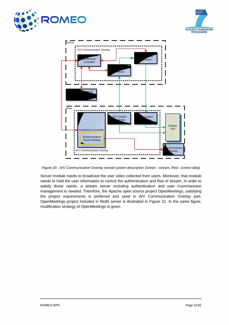
ROMEO A/V Communication Overlay mainly consists of two totally independent components:
Server and Client components as shown in Figure 20. In that diagram, server, peer and
IRACS (Internet Resource & Admission Control Subsystem, which is responsible for QoS
adjustments for A/V) are connected to each other with control (red) and stream (green) data.
Whereas the server component is used as a hub for collaborating users who communicate
with each other, the client component is resided at the user devices in order to let users join in
the video conference.
ROMEO WP6 Page 31/82
Peer
Server
Conference
Controller
A/V Communication Overlay
A/V Content
Distributer
A/V Communication Overlay
Conference Controller
A/V Content
Distributer
Display
Unit
A/V Content
Receiver
A/V Content
Receiver
Synchronisation
Control Module
Synchronization
Module
Internet Resource &
Admission Control
Subsystem (IRACS)
Figure 20 - A/V Communication Overlay overall system description (Green - stream, Red - control data)
Server module needs to broadcast the user video collected from users. Moreover, that module
needs to hold the user information to control the authentication and flow of stream. In order to
satisfy those needs, a stream server including authentication and user /room/session
management is needed. Therefore, the Apache open source project OpenMeetings, satisfying
the project requirements is preferred and used in A/V Communication Overlay part.
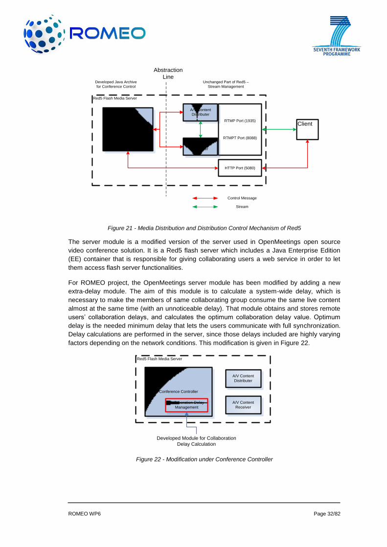
OpenMeetings project included in Red5 server is illustrated in Figure 21. In the same figure,
modification strategy of OpenMeetings is given.
ROMEO WP6 Page 32/82
Red5 Flash Media Server
Conference Controller –
Openmeetings Java
Archive
A/V Content
Distributer
Abstraction
LineDeveloped Java Archive
for Conference Control
Unchanged Part of Red5 –
Stream Management
HTTP Port (5080)
RTMP Port (1935)
RTMPT Port (8088)
Client
A/V Content
Receiver
Control Message
Stream
Figure 21 - Media Distribution and Distribution Control Mechanism of Red5
The server module is a modified version of the server used in OpenMeetings open source
video conference solution. It is a Red5 flash server which includes a Java Enterprise Edition
(EE) container that is responsible for giving collaborating users a web service in order to let
them access flash server functionalities.
For ROMEO project, the OpenMeetings server module has been modified by adding a new
extra-delay module. The aim of this module is to calculate a system-wide delay, which is
necessary to make the members of same collaborating group consume the same live content
almost at the same time (with an unnoticeable delay). That module obtains and stores remote
users’ collaboration delays, and calculates the optimum collaboration delay value. Optimum
delay is the needed minimum delay that lets the users communicate with full synchronization.
Delay calculations are performed in the server, since those delays included are highly varying
factors depending on the network conditions. This modification is given in Figure 22.
Red5 Flash Media Server
Conference Controller
A/V Content
Distributer
A/V Content
Receiver
Collaboration Delay
Management
Developed Module for Collaboration
Delay Calculation
Figure 22 - Modification under Conference Controller
ROMEO WP6 Page 33/82
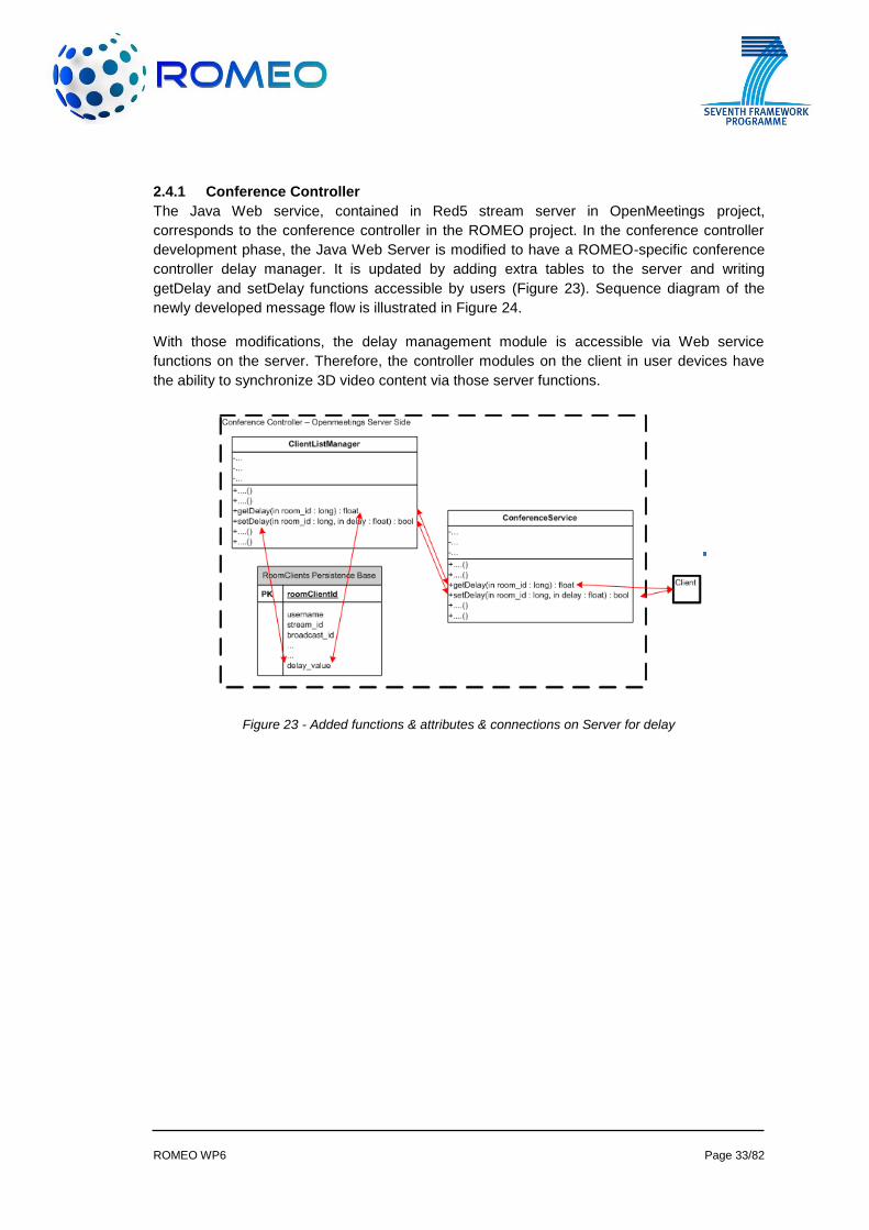
2.4.1 Conference Controller
The Java Web service, contained in Red5 stream server in OpenMeetings project,
corresponds to the conference controller in the ROMEO project. In the conference controller
development phase, the Java Web Server is modified to have a ROMEO-specific conference
controller delay manager. It is updated by adding extra tables to the server and writing
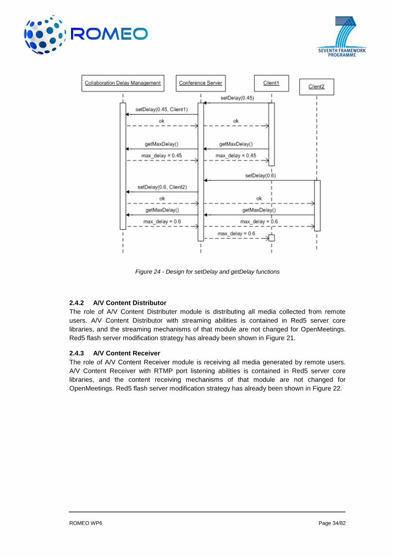
getDelay and setDelay functions accessible by users (Figure 23). Sequence diagram of the
newly developed message flow is illustrated in Figure 24.
With those modifications, the delay management module is accessible via Web service
functions on the server. Therefore, the controller modules on the client in user devices have
the ability to synchronize 3D video content via those server functions.
Figure 23 - Added functions & attributes & connections on Server for delay
ROMEO WP6 Page 34/82
Figure 24 - Design for setDelay and getDelay functions
2.4.2 A/V Content Distributor
The role of A/V Content Distributer module is distributing all media collected from remote
users. A/V Content Distributor with streaming abilities is contained in Red5 server core
libraries, and the streaming mechanisms of that module are not changed for OpenMeetings.
Red5 flash server modification strategy has already been shown in Figure 21.
2.4.3 A/V Content Receiver
The role of A/V Content Receiver module is receiving all media generated by remote users.
A/V Content Receiver with RTMP port listening abilities is contained in Red5 server core
libraries, and the content receiving mechanisms of that module are not changed for
OpenMeetings. Red5 flash server modification strategy has already been shown in Figure 22.
ROMEO WP6 Page 35/82
3 PEER COMPONENTS
3.1 P2P
3.1.1 Topology Controller
The Topology Controller (TC) is a software module that runs at the peer with the following
purposes:
Initial contact with the main server for user authentication and redirection to the
nearest super-peer;
Compute the peer evaluation using peer’s hardware characteristics and network
statistics, as provided by the Network Monitoring Subsystem;
Inform the TB of its intention to consume specific 3D content;
Perform P2P tree operations as commanded by the TB (parent, parent/child or child);
Establish connections with parents for content request and accept connections from
children peers for content forwarding.
Next section describes the most relevant classes used by the TC to perform its operations.
3.1.1.1 Provided Classes
The TC software module is constituted by the following classes:
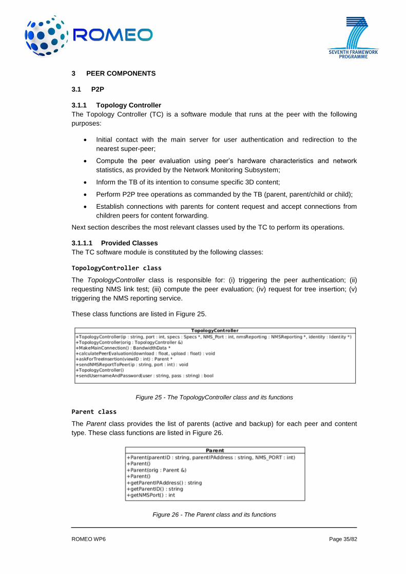
TopologyController class
The TopologyController class is responsible for: (i) triggering the peer authentication; (ii)
requesting NMS link test; (iii) compute the peer evaluation; (iv) request for tree insertion; (v)
triggering the NMS reporting service.
These class functions are listed in Figure 25.
Figure 25 - The TopologyController class and its functions
Parent class
The Parent class provides the list of parents (active and backup) for each peer and content
type. These class functions are listed in Figure 26.
Figure 26 - The Parent class and its functions
ROMEO WP6 Page 36/82
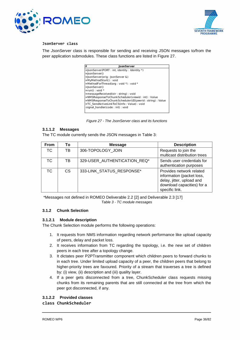
JsonServer class
The JsonServer class is responsible for sending and receiving JSON messages to/from the
peer application submodules. These class functions are listed in Figure 27.
Figure 27 - The JsonServer class and its functions
3.1.1.2 Messages
The TC module currently sends the JSON messages in Table 3:
From To Message Description
TC TB 306-TOPOLOGY_JOIN Requests to join the multicast distribution trees
TC TB 329-USER_AUTHENTICATION_REQ* Sends user credentials for authentication purposes
TC CS 333-LINK_STATUS_RESPONSE* Provides network related information (packet loss, delay, jitter, upload and download capacities) for a specific link.
*Messages not defined in ROMEO Deliverable 2.2 [2] and Deliverable 2.3 [17] Table 3 - TC module messages
3.1.2 Chunk Selection
3.1.2.1 Module description
The Chunk Selection module performs the following operations:
1. It requests from NMS information regarding network performance like upload capacity
of peers, delay and packet loss.
2. It receives information from TC regarding the topology, i.e. the new set of children
peers in each tree after a topology change.
3. It dictates peer P2PTransmitter component which children peers to forward chunks to
in each tree. Under limited upload capacity of a peer, the children peers that belong to
higher-priority trees are favoured. Priority of a stream that traverses a tree is defined
by: (i) view, (ii) description and (iii) quality layer.
4. If a peer gets disconnected from a tree, ChunkScheduler class requests missing
chunks from its remaining parents that are still connected at the tree from which the
peer got disconnected, if any.
3.1.2.2 Provided classes
class ChunkScheduler
ROMEO WP6 Page 37/82
It updates children tables according to information received by TC and NMS, it also updates
the children status, computes the incoming bitrate from P2PReceiver and updates the
DestinationIPList of PeerP2PTransmitter. The ChunkScheduler class includes the following
methods:
ChunkScheduler(int, GetAppConfig*);
void ResetChildrenStatus();
void InsertChild(int, int, std::string);
void RemoveChildren();
void ActivateChild(int, int, std::string);
void DeactivateChild(int, int, std::string);
void SetUploadCapacity(double);
void SetPktLoss(double);
void ComputeBitrates(int);
void ApplySelectionPolicy();
~ChunkScheduler();
class InterfaceToNMSforCapacity
It connects to NMS, requests report on the upload capacity of a peer and updates the peer status. The InterfaceToNMSforCapacity class includes the following methods:
InterfaceToNMS forCapacity (ChunkScheduler*);
void QueryNMS forCapacity (std::string, std::string, uint16_t);
void *run();
class InterfaceToNMSforPktLoss
It connects to NMS, periodically requests reports on network performance metrics (packet loss, jitter and delay) and updates the children status. The InterfaceToNMSforPktLoss class
includes the following methods:
InterfaceToNMSforPktLoss (ChunkScheduler*);
void QueryNMSforPktLoss (std::string, std::string, uint16_t);
void *run();
class InterfaceToTC
It connects to TC, receives updates about the current children and updates the children list accordingly. The InterfaceToTC class includes the following methods:
InterfaceToTC(ChunkScheduler*);
void ReceiveEventsFromTC();
void UpdateChildren(int, int, std::string);
ROMEO WP6 Page 38/82
void *run();
class InterfaceToCS
It connects to CS of parent peers in all trees and requests missing chunks when necessary. At the parent side, it responds with its availability to provide missing chunks. At the child side, it asks the parent peer to initiate transfer of missing chunks. The InterfaceToCS class includes
the following methods:
InterfaceToCS(ChunkScheduler*);
void QueryCS (std::string, std::string, uint16_t);
void ReceiveEventsFromCS();
void InitiateTransfer(int);
void CheckAvailability(int);
void UpdateChildren(int, int, std::string);
void *run();
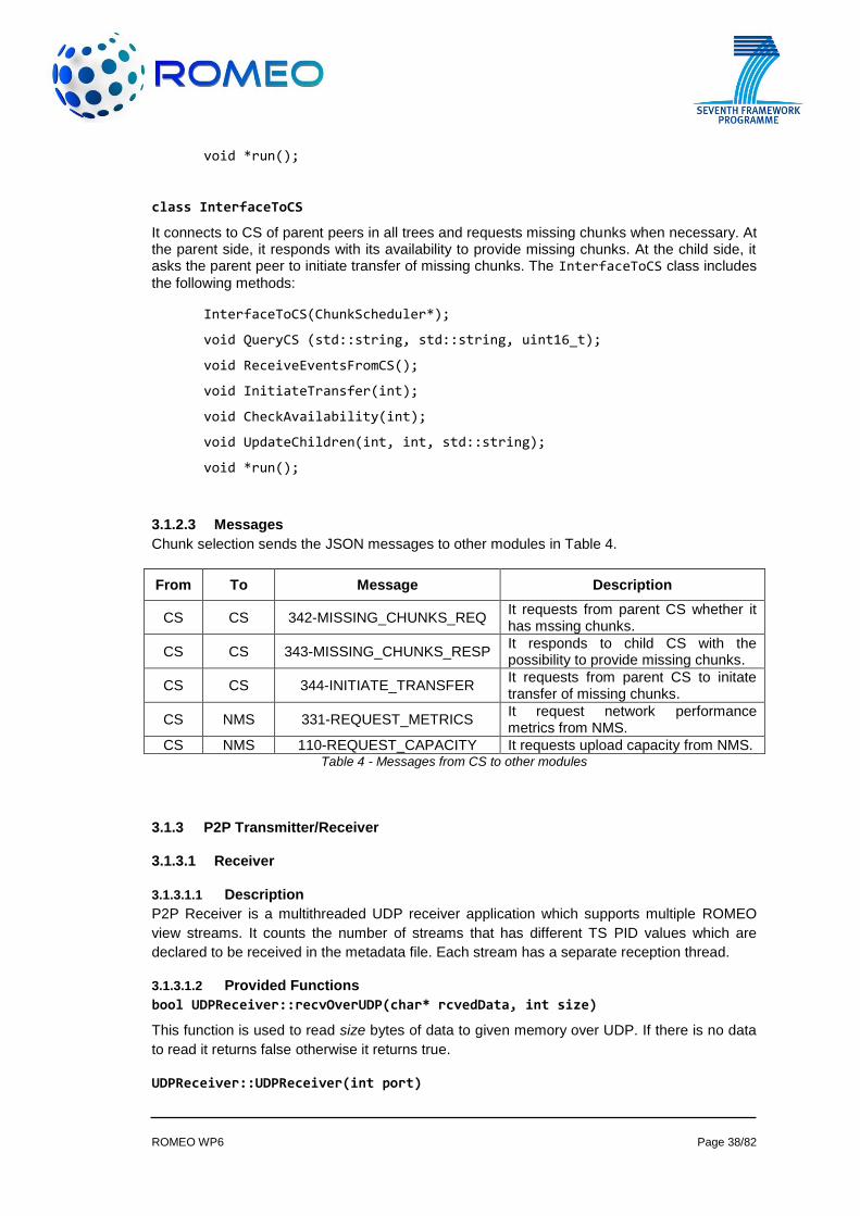
3.1.2.3 Messages
Chunk selection sends the JSON messages to other modules in Table 4.
From To Message Description
CS CS 342-MISSING_CHUNKS_REQ It requests from parent CS whether it has mssing chunks.
CS CS 343-MISSING_CHUNKS_RESP It responds to child CS with the possibility to provide missing chunks.
CS CS 344-INITIATE_TRANSFER It requests from parent CS to initate transfer of missing chunks.
CS NMS 331-REQUEST_METRICS It request network performance metrics from NMS.
CS NMS 110-REQUEST_CAPACITY It requests upload capacity from NMS. Table 4 - Messages from CS to other modules
3.1.3 P2P Transmitter/Receiver
3.1.3.1 Receiver
3.1.3.1.1 Description
P2P Receiver is a multithreaded UDP receiver application which supports multiple ROMEO
view streams. It counts the number of streams that has different TS PID values which are
declared to be received in the metadata file. Each stream has a separate reception thread.
3.1.3.1.2 Provided Functions
bool UDPReceiver::recvOverUDP(char* rcvedData, int size)
This function is used to read size bytes of data to given memory over UDP. If there is no data
to read it returns false otherwise it returns true.
UDPReceiver::UDPReceiver(int port)
ROMEO WP6 Page 39/82
This function is used to configurethe receiver to listen in a given port.
void GetAppConfig::readConfigFiles(std::string& metaDataFile, std::string& appConfigFile)
This function is used to read configuration files to configure receiver.
3.1.3.2 PeerP2PTransmitter
3.1.3.2.1 Description
The PeerP2PTransmitter is a multithreaded UDP transmitter application which supports
multiple ROMEO view streams. It is used to re-transmit the received data to the peers
selected in ROMEO network. The main difference between P2PTransmitter and
PeerP2PTransmitter is P2PTransmitter send all streams to its destination IP list but
PeerP2PTransmitter sends selected streams to selected peers.
3.1.3.2.2 Provided Functions
void SocketListenerThread::SocketListenerThread(int tsPID, int port)
This function is used to receive given TS PID identified stream from given UDP port and stores
the chunks to a separate stream queue.
void StreamSenderThread::transmitChunks(void)
This function is used to transmit its chunks to its pre-selected IP list.
3.1.4 P2P Depacketisation
3.1.4.1 Description
This module is responsible for decapsulation of the media from P2P chunks received over the
P2P network.
3.1.4.2 Provided Functions
void StreamReceiverThread::GetChunksOverUDP()
This function is used to decapsulate the P2P packet, decrypt the data and send it to Chunk
Selection and Synchronisation modules. It is also a part of receiver module.
bool UDPTransmitter::sendDataOverUDP(char* dataToSend, int size, char* dest_addr, int port)
This function is used to send received and depacketised data to given IP and port. It is
required for communicating with Chunk selection and Synchronisation modules.
3.2 DVB Reception
3.2.1 Fixed/Portable Terminals
DVB reception on peer terminals is provided by PCTV NanoStick, which is capable of
receiving DVB-T/T2 signals with terrestrial signal receiver antennas (or direct cable) with MCX
connectors. The NanoStick hardware is connected to the platform via an USB 2.0 interface.
PCTV provides software with the hardware (tuner, remote control and antenna). The PCTV
package has player software for DVB transport stream. This software can be installed on a
platform running MS Windows. PCTV does not give any support for Linux OS. Linux OS needs
some library installations over standard Linux distributions. Libraries, from Linux DVB API, that
are listed below have been included in the DVB reception module.
FRONTEND
ROMEO WP6 Page 40/82
DEMUX
DVR
By the help of these libraries, actions listed below have been achieved and software to
perform these actions has been developed:
getting tuner capabilities
setting DVB tuning parameters
o Frequency
o Bandwidth
o FEC rate
o Inversion
o Constellation
o Transmission Mode
o Guard Interval
o Hierarchy Information
controlling DEMUX filters
receiving the Transport Stream via DVR
User Interface module provides an interface for setting the DVB parameters (Section 3.8.1).
The DVB reception module takes the required parameters from the user interface. All other
operations such as tuning, DEMUX filtering, and starting DVR are performed automatically by
the DVB reception module.
After the Transport Stream is successfully received via DVB, it is handed down the
synchronization module, which includes a stream parser for MPEG Transport Stream, extracts
the elementary streams and service information (DVB-SI) tables from the stream. The
extracted data is then used for synchronizing the streams and feeding the decoders.
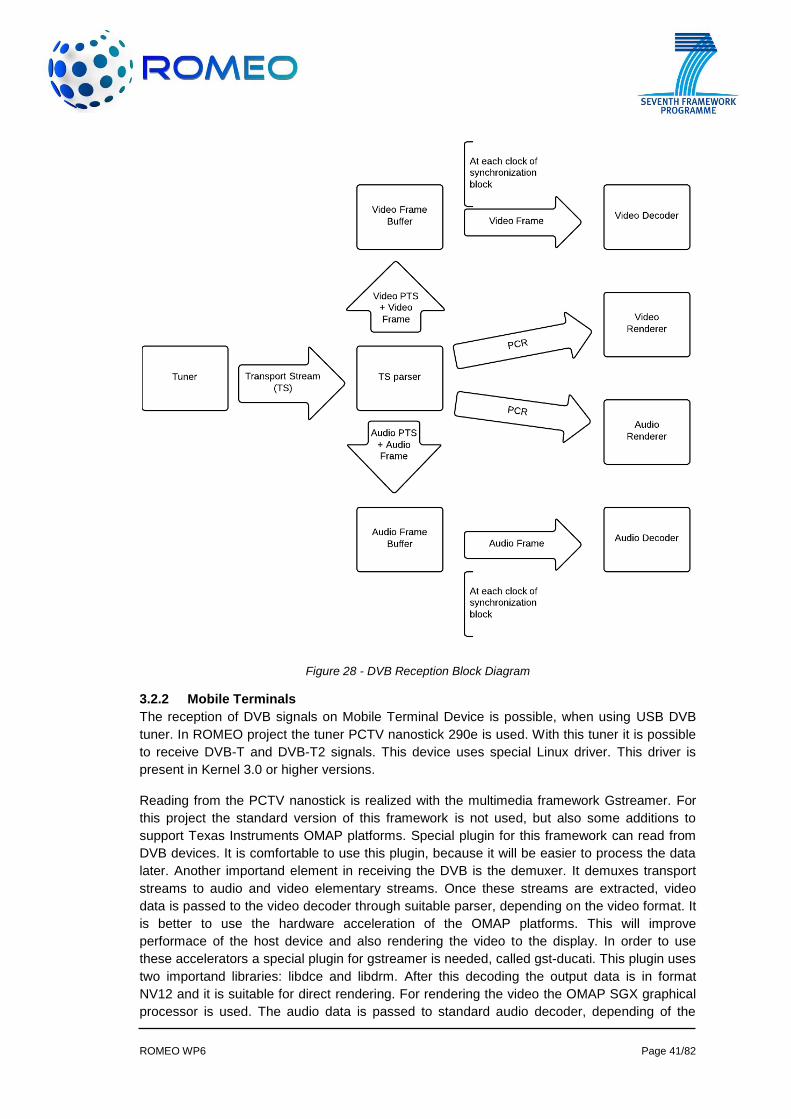
The working principle of DVB reception module on portable and fixed terminals and its
connection to the synchronization module can be summarized as follows:
The received stream is parsed via the stream parser. The parser extracts required information
and processes them as needed. It sends PCR to both video and audio renderers whenever it
receives. Additionally, it creates elementary stream frames (video, audio) and stores them in a
buffer. The frames are stored in the buffer with their Presentation Time Stamp (PTS). The time
stamp information is then used by synchronization module to synchronize the DVB reception
buffer with the P2P receiver’s buffers. Then, synchronization module’s clock starts, which
determines the time stamps (PTS) of the frame to be sent to the decoders. As the DVB
reception module receives timestamp from the synchronization module, it sends the related
frame to the decoders (Figure 28).
ROMEO WP6 Page 41/82
Figure 28 - DVB Reception Block Diagram
3.2.2 Mobile Terminals
The reception of DVB signals on Mobile Terminal Device is possible, when using USB DVB
tuner. In ROMEO project the tuner PCTV nanostick 290e is used. With this tuner it is possible
to receive DVB-T and DVB-T2 signals. This device uses special Linux driver. This driver is
present in Kernel 3.0 or higher versions.
Reading from the PCTV nanostick is realized with the multimedia framework Gstreamer. For
this project the standard version of this framework is not used, but also some additions to
support Texas Instruments OMAP platforms. Special plugin for this framework can read from
DVB devices. It is comfortable to use this plugin, because it will be easier to process the data
later. Another importand element in receiving the DVB is the demuxer. It demuxes transport
streams to audio and video elementary streams. Once these streams are extracted, video
data is passed to the video decoder through suitable parser, depending on the video format. It
is better to use the hardware acceleration of the OMAP platforms. This will improve
performace of the host device and also rendering the video to the display. In order to use
these accelerators a special plugin for gstreamer is needed, called gst-ducati. This plugin uses
two importand libraries: libdce and libdrm. After this decoding the output data is in format
NV12 and it is suitable for direct rendering. For rendering the video the OMAP SGX graphical
processor is used. The audio data is passed to standard audio decoder, depending of the
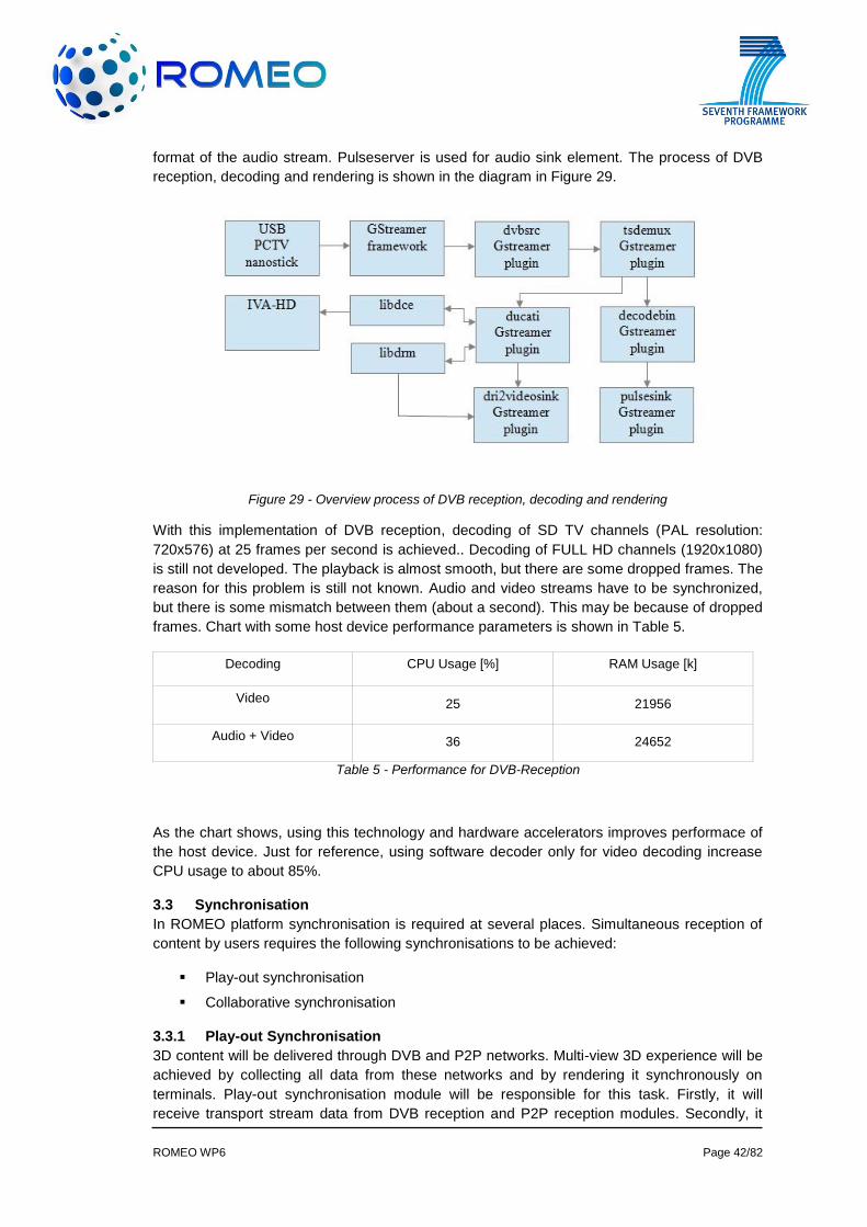
ROMEO WP6 Page 42/82
format of the audio stream. Pulseserver is used for audio sink element. The process of DVB
reception, decoding and rendering is shown in the diagram in Figure 29.
Figure 29 - Overview process of DVB reception, decoding and rendering
With this implementation of DVB reception, decoding of SD TV channels (PAL resolution:
720x576) at 25 frames per second is achieved.. Decoding of FULL HD channels (1920x1080)
is still not developed. The playback is almost smooth, but there are some dropped frames. The
reason for this problem is still not known. Audio and video streams have to be synchronized,
but there is some mismatch between them (about a second). This may be because of dropped
frames. Chart with some host device performance parameters is shown in Table 5.
Decoding CPU Usage [%] RAM Usage [k]
Video 25 21956
Audio + Video 36 24652
Table 5 - Performance for DVB-Reception
As the chart shows, using this technology and hardware accelerators improves performace of
the host device. Just for reference, using software decoder only for video decoding increase
CPU usage to about 85%.
3.3 Synchronisation
In ROMEO platform synchronisation is required at several places. Simultaneous reception of
content by users requires the following synchronisations to be achieved:
Play-out synchronisation
Collaborative synchronisation
3.3.1 Play-out Synchronisation
3D content will be delivered through DVB and P2P networks. Multi-view 3D experience will be
achieved by collecting all data from these networks and by rendering it synchronously on
terminals. Play-out synchronisation module will be responsible for this task. Firstly, it will
receive transport stream data from DVB reception and P2P reception modules. Secondly, it
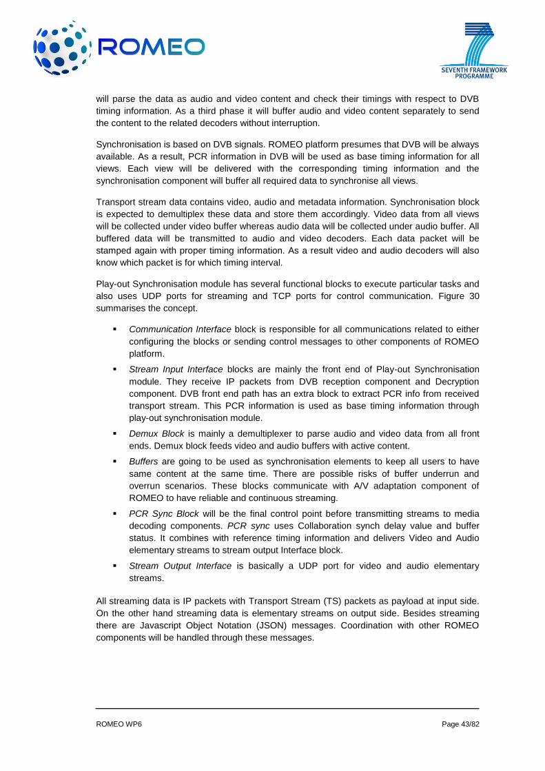
ROMEO WP6 Page 43/82
will parse the data as audio and video content and check their timings with respect to DVB
timing information. As a third phase it will buffer audio and video content separately to send
the content to the related decoders without interruption.
Synchronisation is based on DVB signals. ROMEO platform presumes that DVB will be always
available. As a result, PCR information in DVB will be used as base timing information for all
views. Each view will be delivered with the corresponding timing information and the
synchronisation component will buffer all required data to synchronise all views.
Transport stream data contains video, audio and metadata information. Synchronisation block
is expected to demultiplex these data and store them accordingly. Video data from all views
will be collected under video buffer whereas audio data will be collected under audio buffer. All
buffered data will be transmitted to audio and video decoders. Each data packet will be
stamped again with proper timing information. As a result video and audio decoders will also
know which packet is for which timing interval.
Play-out Synchronisation module has several functional blocks to execute particular tasks and
also uses UDP ports for streaming and TCP ports for control communication. Figure 30
summarises the concept.
Communication Interface block is responsible for all communications related to either
configuring the blocks or sending control messages to other components of ROMEO
platform.
Stream Input Interface blocks are mainly the front end of Play-out Synchronisation
module. They receive IP packets from DVB reception component and Decryption
component. DVB front end path has an extra block to extract PCR info from received
transport stream. This PCR information is used as base timing information through
play-out synchronisation module.
Demux Block is mainly a demultiplexer to parse audio and video data from all front
ends. Demux block feeds video and audio buffers with active content.
Buffers are going to be used as synchronisation elements to keep all users to have
same content at the same time. There are possible risks of buffer underrun and
overrun scenarios. These blocks communicate with A/V adaptation component of
ROMEO to have reliable and continuous streaming.
PCR Sync Block will be the final control point before transmitting streams to media
decoding components. PCR sync uses Collaboration synch delay value and buffer
status. It combines with reference timing information and delivers Video and Audio
elementary streams to stream output Interface block.
Stream Output Interface is basically a UDP port for video and audio elementary
streams.
All streaming data is IP packets with Transport Stream (TS) packets as payload at input side.
On the other hand streaming data is elementary streams on output side. Besides streaming
there are Javascript Object Notation (JSON) messages. Coordination with other ROMEO
components will be handled through these messages.
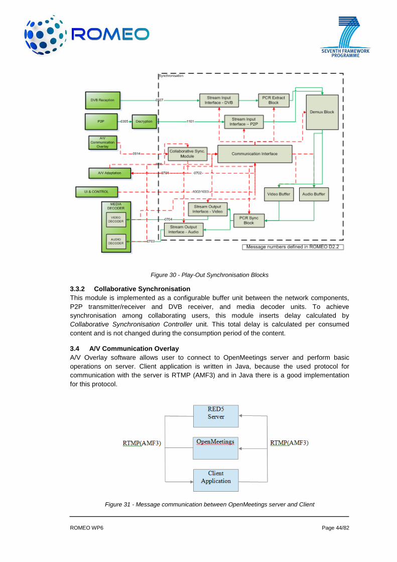
ROMEO WP6 Page 44/82
Figure 30 - Play-Out Synchronisation Blocks
3.3.2 Collaborative Synchronisation
This module is implemented as a configurable buffer unit between the network components,
P2P transmitter/receiver and DVB receiver, and media decoder units. To achieve
synchronisation among collaborating users, this module inserts delay calculated by
Collaborative Synchronisation Controller unit. This total delay is calculated per consumed
content and is not changed during the consumption period of the content.
3.4 A/V Communication Overlay
A/V Overlay software allows user to connect to OpenMeetings server and perform basic
operations on server. Client application is written in Java, because the used protocol for
communication with the server is RTMP (AMF3) and in Java there is a good implementation
for this protocol.
Figure 31 - Message communication between OpenMeetings server and Client
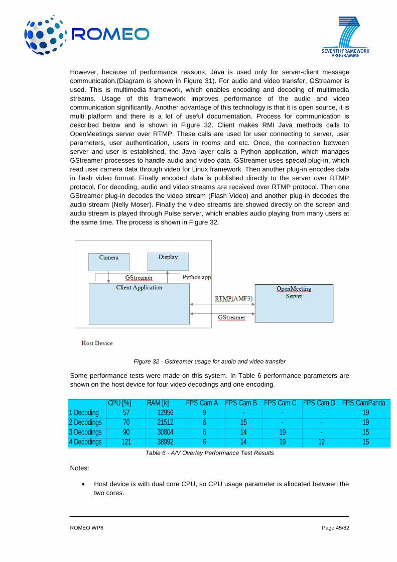
ROMEO WP6 Page 45/82
However, because of performance reasons, Java is used only for server-client message
communication.(Diagram is shown in Figure 31). For audio and video transfer, GStreamer is
used. This is multimedia framework, which enables encoding and decoding of multimedia
streams. Usage of this framework improves performance of the audio and video
communication significantly. Another advantage of this technology is that it is open source, it is
multi platform and there is a lot of useful documentation. Process for communication is
described below and is shown in Figure 32. Client makes RMI Java methods calls to
OpenMeetings server over RTMP. These calls are used for user connecting to server, user
parameters, user authentication, users in rooms and etc. Once, the connection between
server and user is established, the Java layer calls a Python application, which manages
GStreamer processes to handle audio and video data. GStreamer uses special plug-in, which
read user camera data through video for Linux framework. Then another plug-in encodes data
in flash video format. Finally encoded data is published directly to the server over RTMP
protocol. For decoding, audio and video streams are received over RTMP protocol. Then one
GStreamer plug-in decodes the video stream (Flash Video) and another plug-in decodes the
audio stream (Nelly Moser). Finally the video streams are showed directly on the screen and
audio stream is played through Pulse server, which enables audio playing from many users at
the same time. The process is shown in Figure 32.
Figure 32 - Gstreamer usage for audio and video transfer
Some performance tests were made on this system. In Table 6 performance parameters are
shown on the host device for four video decodings and one encoding.
Table 6 - A/V Overlay Performance Test Results
Notes:
Host device is with dual core CPU, so CPU usage parameter is allocated between the
two cores.
CPU [%] RAM [k] FPS Cam A FPS Cam B FPS Cam C FPS Cam D FPS CamPanda
1 Decoding 57 12956 9 - - - 19
2 Decodings 70 21512 6 15 - - 19
3 Decodings 90 30804 6 14 19 - 15
4 Decodings 121 38992 6 14 19 12 15
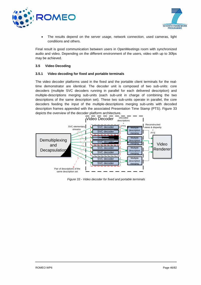
ROMEO WP6 Page 46/82
The results depend on the server usage, network connection, used cameras, light
conditions and others.
Final result is good communication between users in OpenMeetings room with synchronized
audio and video. Depending on the different environment of the users, video with up to 30fps
may be achieved.
3.5 Video Decoding
3.5.1 Video decoding for fixed and portable terminals
The video decoder platforms used in the fixed and the portable client terminals for the real-
time demonstrator are identical. The decoder unit is composed of two sub-units: core
decoders (multiple SVC decoders running in parallel for each delivered description) and
multiple-descriptions merging sub-units (each sub-unit in charge of combining the two
descriptions of the same description set). These two sub-units operate in parallel, the core
decoders feeding the input of the multiple-descriptions merging sub-units with decoded
description frames appended with the associated Presentation Time Stamp (PTS). Figure 33
depicts the overview of the decoder platform architecture.
Figure 33 - Video decoder for fixed and portable terminals
Video Decoder
Demultiplexing
and
Decapsulation
SVC decoder
Video
Renderer
Multiple
description
mergingSVC decoder
SVC decoder
SVC decoder
SVC decoder
SVC decoder
SVC decoder
SVC decoder
Multiple
description
merging
Multiple
description
merging
Multiple
description
merging
SVC elementary
streams
Pair of descriptions of the
same description set
Decoded
descriptions
+
PTSReconstructed
views & disparity
+
PTS
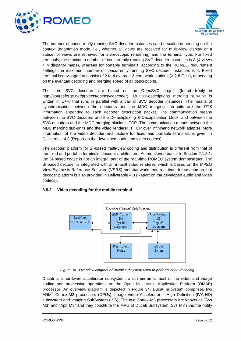
ROMEO WP6 Page 47/82
The number of concurrently running SVC decoder instances can be scaled depending on the
context (adaptation mode, i.e., whether all views are received for multi-view display or a
subset of views are retrieved for stereoscopic rendering) and the terminal type. For fixed
terminals, the maximum number of concurrently running SVC decoder instances is 8 (4 views
+ 4 disparity maps), whereas for portable terminals, according to the ROMEO requirement
settings the maximum number of concurrently running SVC decoder instances is 4. Fixed
terminal is envisaged to consist of 2 to 4 average 2-core work stations (> 2.8 GHz), depending
on the eventual decoding and merging speed of all descriptions.
The core SVC decoders are based on the OpenSVC project (found freely in
http://sourceforge.net/projects/opensvcdecoder). Multiple-descriptions merging sub-unit is
written in C++, that runs in parallel with a pair of SVC decoder instances. The means of
synchronisation between the decoders and the MDC merging sub-units are the PTS
information appended to each decoder description packet. The communication means
between the SVC decoders and the Demuliplexing & Decapsulation block, and between the
SVC decoders and the MDC merging blocks is TCP. The communication means between the
MDC merging sub-units and the video renderer is TCP over infiniband network adapter. More
information of the video decoder architecture for fixed and portable terminals is given in
Deliverable 4.3 (Report on the developed audio and video codecs).
The decoder platform for SI-based multi-view coding and distribution is different from that of
the fixed and portable terminals’ decoder architecture. As mentioned earlier in Section 2.1.3.1,
the SI-based codec is not an integral part of the real-time ROMEO system demonstrator. The
SI-based decoder is integrated with an in-built video renderer, which is based on the MPEG
View Synthesis Reference Software (VSRS) tool that works non real-time. Information on that
decoder platform is also provided in Deliverable 4.3 (Report on the developed audio and video
codecs).
3.5.2 Video decoding for the mobile terminal
Figure 34 - Overview diagram of Ducati subsystem used to perform video decoding
Ducati is a hardware accelerator subsystem, which performs most of the video and image
coding and processing operations on the Open Multimedia Application Platform (OMAP)
processor. An overview diagram is depicted in Figure 34. Ducati subystem comprises two
ARM® Cortex-M3 processors (CPUs), Image Video Accelerator – High Definition (IVA-HD)
subsystem and Imaging SubSystem (ISS). The two Cortex-M3 processors are known as “Sys
M3” and “App M3” and they constitute the MPU of Ducati Subsystem. Sys M3 runs the notify
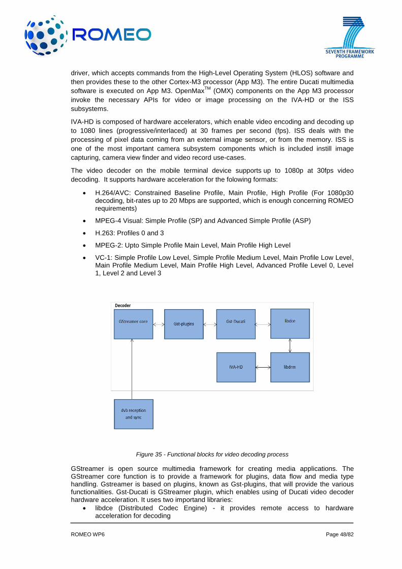
ROMEO WP6 Page 48/82
driver, which accepts commands from the High-Level Operating System (HLOS) software and
then provides these to the other Cortex-M3 processor (App M3). The entire Ducati multimedia
software is executed on App M3. OpenMaxTM
(OMX) components on the App M3 processor
invoke the necessary APIs for video or image processing on the IVA-HD or the ISS
subsystems.
IVA-HD is composed of hardware accelerators, which enable video encoding and decoding up
to 1080 lines (progressive/interlaced) at 30 frames per second (fps). ISS deals with the
processing of pixel data coming from an external image sensor, or from the memory. ISS is
one of the most important camera subsystem components which is included instill image
capturing, camera view finder and video record use-cases.
The video decoder on the mobile terminal device supports up to 1080p at 30fps video
decoding. It supports hardware acceleration for the folowing formats:
H.264/AVC: Constrained Baseline Profile, Main Profile, High Profile (For 1080p30 decoding, bit-rates up to 20 Mbps are supported, which is enough concerning ROMEO requirements)
MPEG-4 Visual: Simple Profile (SP) and Advanced Simple Profile (ASP)
H.263: Profiles 0 and 3
MPEG-2: Upto Simple Profile Main Level, Main Profile High Level
VC-1: Simple Profile Low Level, Simple Profile Medium Level, Main Profile Low Level, Main Profile Medium Level, Main Profile High Level, Advanced Profile Level 0, Level 1, Level 2 and Level 3
Figure 35 - Functional blocks for video decoding process
GStreamer is open source multimedia framework for creating media applications. The GStreamer core function is to provide a framework for plugins, data flow and media type handling. Gstreamer is based on plugins, known as Gst-plugins, that will provide the various functionalities. Gst-Ducati is GStreamer plugin, which enables using of Ducati video decoder hardware acceleration. It uses two importand libraries:
libdce (Distributed Codec Engine) - it provides remote access to hardware acceleration for decoding

ROMEO WP6 Page 49/82
libdrm (Direct Rendering Manager) - it provides routines for the X Window System, which is a computer software system and network protocol that provides a basis for Graphical User Interfaces and rich input device capability for networked computers, to directly interface with video hardware.
IVA-HD (Image Video Accelerator - High Definition) are hardware accelerators in OMAP processors, which enables HD video decoding and stereoscopic 3D.
The functional block diagram is given in Figure 35.
3.5.3 Audio Decode and Rendering
3.5.3.1 Interface from Audio Decoder to Audio Renderer
The transport of decoded audio data to the corresponding renderer engine is implemented via
IP transmission. This allows a physical separation of the hosts for rendering and decoding. For
renderers running on the same host as the decoder data packets are sent to the local
loopback. Each decoded audio stream goes out to an individual port using the UDP transport
protocol. The packets have got a header containing information about the samples included.
The time reference for synchronization – the Presentation Time Stamp (PTS) – is put in here,
too. Renderers on mobile and portable terminals receive the program clock reference (PCR)
on a TCP network socket. The PCR is packetized in the JSON format. The audio samples are
getting buffered and rendered when the PCR matches the PTS value.
3.5.4 Audio Decoder
The audio decoder software application has been developed and distributed. Named
aacDecoderApp.exe, this decodes incoming AAC frames and sends the decoded frames to
another terminal over UDP/TCP connection. It accepts the following as the input parameters:
protocol (UDP or TCP)
SrcPort (port number to receive the frames from)
DstIPAddr (destination IP address)
DestPort (destination port number)
WriteToFilename.pcm (the first channel of the decoded frames is written as a local
file in raw PCM format for later playback and debugging)
The format of each incoming aac packet is supposed as a complete AAC encoded frame
prefixed with 8-byte PTS information as in Figure 36:
Figure 36 - Incoming audio packet structure
The PTS is increased by 1920 for each following frame. The number of 1920 comes from this
assumption: 48 KHz sampling rate, 1024 samples was encoded in each frame; the PTS is 90
KHz, so that the frame time in terms of PTS ticks is 1024/48000 * 90000 = 1920, which is
equivalent to 21.333 ms.
The output data for each decoded audio frame has the format as in Figure 37 and Figure 38.
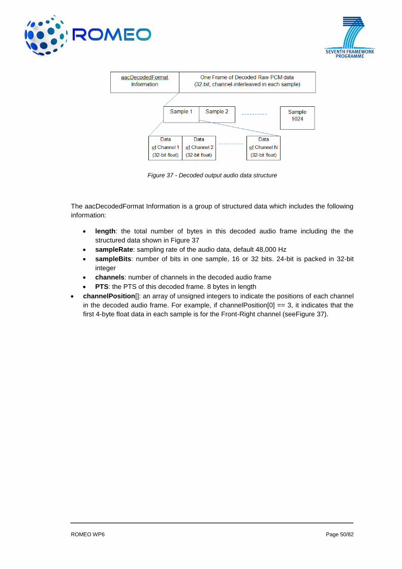
ROMEO WP6 Page 50/82
Figure 37 - Decoded output audio data structure
The aacDecodedFormat Information is a group of structured data which includes the following
information:
length: the total number of bytes in this decoded audio frame including the the
structured data shown in Figure 37
sampleRate: sampling rate of the audio data, default 48,000 Hz
sampleBits: number of bits in one sample, 16 or 32 bits. 24-bit is packed in 32-bit
integer
channels: number of channels in the decoded audio frame
PTS: the PTS of this decoded frame. 8 bytes in length
channelPosition[]: an array of unsigned integers to indicate the positions of each channel
in the decoded audio frame. For example, if channelPosition[0] == 3, it indicates that the
first 4-byte float data in each sample is for the Front-Right channel (seeFigure 37).
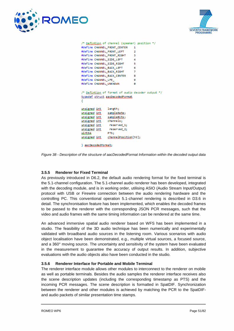
ROMEO WP6 Page 51/82
Figure 38 - Description of the structure of aacDecodedFormat Information within the decoded output data
3.5.5 Renderer for Fixed Terminal
As previously introduced in D6.2, the default audio rendering format for the fixed terminal is
the 5.1-channel configuration. The 5.1-channel audio renderer has been developed, integrated
with the decoding module, and is in working order, utilising ASIO (Audio Stream Input/Output)
protocol with USB or Firewire connection between the audio rendering hardware and the
controlling PC. This conventional operation 5.1-channel rendering is described in D3.6 in
detail. The synchronisation feature has been implemented, which enables the decoded frames
to be passed to the renderer with the corresponding JSON PCR messages, such that the
video and audio frames with the same timing information can be rendered at the same time.
An advanced immersive spatial audio renderer based on WFS has been implemented in a
studio. The feasibility of the 3D audio technique has been numerically and experimentally
validated with broadband audio sources in the listening room. Various scenarios with audio
object localisation have been demonstrated, e.g., multiple virtual sources, a focused source,
and a 360° moving source. The uncertainty and sensitivity of the system have been evaluated
in the measurement to guarantee the accuracy of output results. In addition, subjective
evaluations with the audio objects also have been conducted in the studio.
3.5.6 Renderer Interface for Portable and Mobile Terminal
The renderer interface module allows other modules to interconnect to the renderer on mobile
as well as portable terminals. Besides the audio samples the renderer interface receives also
the scene description updates (including the corresponding timestamp as PTS) and the
incoming PCR messages. The scene description is formatted in SpatDIF. Synchronization
between the renderer and other modules is achieved by matching the PCR to the SpatDIF-
and audio packets of similar presentation time stamps.
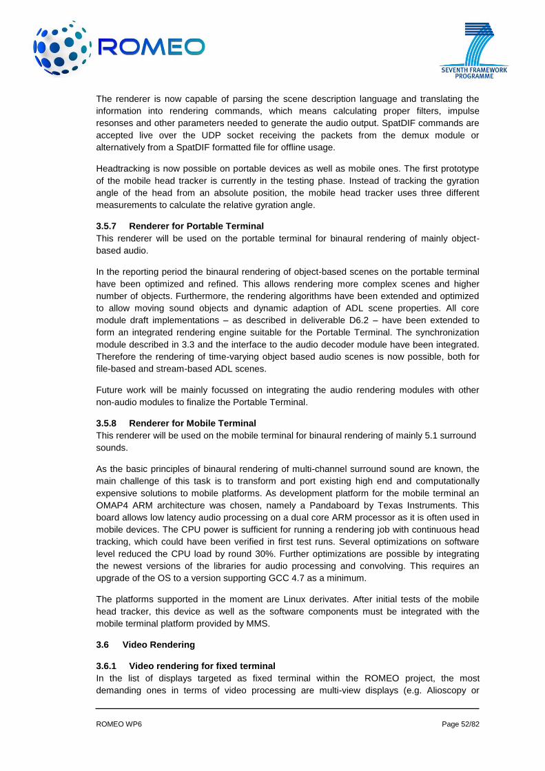
ROMEO WP6 Page 52/82
The renderer is now capable of parsing the scene description language and translating the
information into rendering commands, which means calculating proper filters, impulse
resonses and other parameters needed to generate the audio output. SpatDIF commands are
accepted live over the UDP socket receiving the packets from the demux module or
alternatively from a SpatDIF formatted file for offline usage.
Headtracking is now possible on portable devices as well as mobile ones. The first prototype
of the mobile head tracker is currently in the testing phase. Instead of tracking the gyration
angle of the head from an absolute position, the mobile head tracker uses three different
measurements to calculate the relative gyration angle.
3.5.7 Renderer for Portable Terminal
This renderer will be used on the portable terminal for binaural rendering of mainly object-
based audio.
In the reporting period the binaural rendering of object-based scenes on the portable terminal
have been optimized and refined. This allows rendering more complex scenes and higher
number of objects. Furthermore, the rendering algorithms have been extended and optimized
to allow moving sound objects and dynamic adaption of ADL scene properties. All core
module draft implementations – as described in deliverable D6.2 – have been extended to
form an integrated rendering engine suitable for the Portable Terminal. The synchronization
module described in 3.3 and the interface to the audio decoder module have been integrated.
Therefore the rendering of time-varying object based audio scenes is now possible, both for
file-based and stream-based ADL scenes.
Future work will be mainly focussed on integrating the audio rendering modules with other
non-audio modules to finalize the Portable Terminal.
3.5.8 Renderer for Mobile Terminal
This renderer will be used on the mobile terminal for binaural rendering of mainly 5.1 surround
sounds.
As the basic principles of binaural rendering of multi-channel surround sound are known, the
main challenge of this task is to transform and port existing high end and computationally
expensive solutions to mobile platforms. As development platform for the mobile terminal an
OMAP4 ARM architecture was chosen, namely a Pandaboard by Texas Instruments. This
board allows low latency audio processing on a dual core ARM processor as it is often used in
mobile devices. The CPU power is sufficient for running a rendering job with continuous head
tracking, which could have been verified in first test runs. Several optimizations on software
level reduced the CPU load by round 30%. Further optimizations are possible by integrating
the newest versions of the libraries for audio processing and convolving. This requires an
upgrade of the OS to a version supporting GCC 4.7 as a minimum.
The platforms supported in the moment are Linux derivates. After initial tests of the mobile
head tracker, this device as well as the software components must be integrated with the
mobile terminal platform provided by MMS.
3.6 Video Rendering
3.6.1 Video rendering for fixed terminal
In the list of displays targeted as fixed terminal within the ROMEO project, the most
demanding ones in terms of video processing are multi-view displays (e.g. Alioscopy or
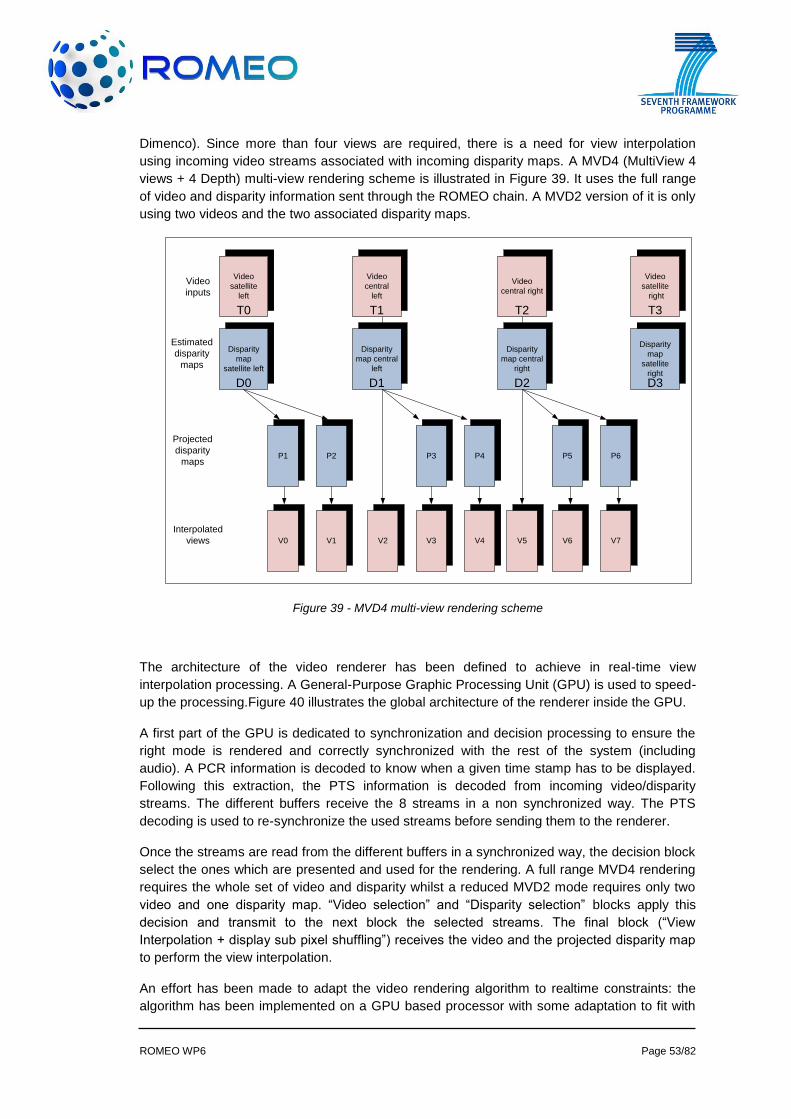
ROMEO WP6 Page 53/82
Dimenco). Since more than four views are required, there is a need for view interpolation
using incoming video streams associated with incoming disparity maps. A MVD4 (MultiView 4
views + 4 Depth) multi-view rendering scheme is illustrated in Figure 39. It uses the full range
of video and disparity information sent through the ROMEO chain. A MVD2 version of it is only
using two videos and the two associated disparity maps.
Disparity
map
satellite left
P1 P2 P3 P4 P5 P6
Video
satellite
left
Video
satellite
right
V0 V1 V2 V3 V4 V5 V6 V7
Projected
disparity
maps
Interpolated
views
Estimated
disparity
maps
Video
inputs
Video
central
left
Video
central right
Disparity
map central
left
Disparity
map central
right
Disparity
map
satellite
right
T0 T1 T2 T3
D0 D1 D2 D3
Figure 39 - MVD4 multi-view rendering scheme
The architecture of the video renderer has been defined to achieve in real-time view
interpolation processing. A General-Purpose Graphic Processing Unit (GPU) is used to speed-
up the processing.Figure 40 illustrates the global architecture of the renderer inside the GPU.
A first part of the GPU is dedicated to synchronization and decision processing to ensure the
right mode is rendered and correctly synchronized with the rest of the system (including
audio). A PCR information is decoded to know when a given time stamp has to be displayed.
Following this extraction, the PTS information is decoded from incoming video/disparity
streams. The different buffers receive the 8 streams in a non synchronized way. The PTS
decoding is used to re-synchronize the used streams before sending them to the renderer.
Once the streams are read from the different buffers in a synchronized way, the decision block
select the ones which are presented and used for the rendering. A full range MVD4 rendering
requires the whole set of video and disparity whilst a reduced MVD2 mode requires only two
video and one disparity map. “Video selection” and “Disparity selection” blocks apply this
decision and transmit to the next block the selected streams. The final block (“View
Interpolation + display sub pixel shuffling”) receives the video and the projected disparity map
to perform the view interpolation.
An effort has been made to adapt the video rendering algorithm to realtime constraints: the
algorithm has been implemented on a GPU based processor with some adaptation to fit with
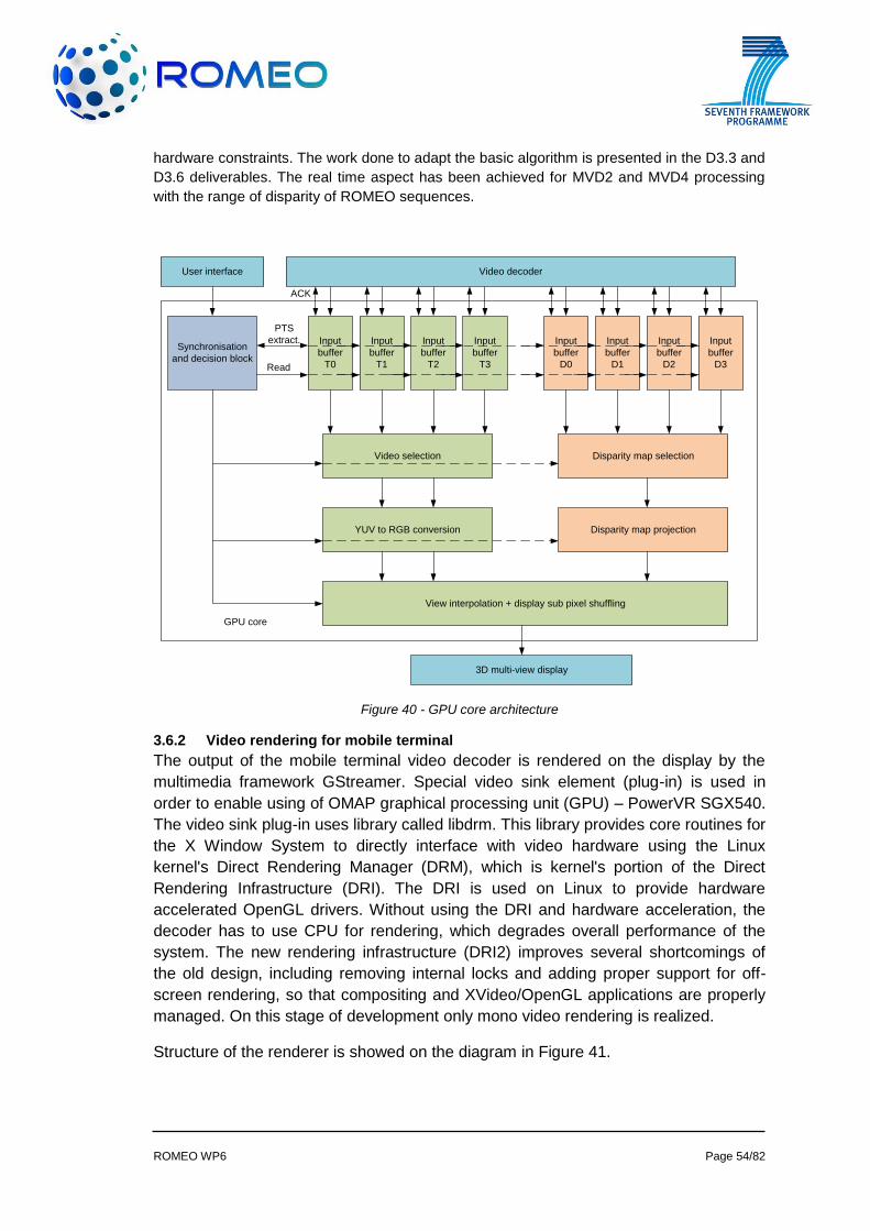
ROMEO WP6 Page 54/82
hardware constraints. The work done to adapt the basic algorithm is presented in the D3.3 and
D3.6 deliverables. The real time aspect has been achieved for MVD2 and MVD4 processing
with the range of disparity of ROMEO sequences.
Input
buffer
T0
Input
buffer
T1
Input
buffer
T2
Input
buffer
T3
Input
buffer
D0
Input
buffer
D1
Input
buffer
D2
Input
buffer
D3
Synchronisation
and decision block
Video selection Disparity map selection
YUV to RGB conversion Disparity map projection
View interpolation + display sub pixel shuffling
Video decoderUser interface
Read
3D multi-view display
GPU core
ACK
PTS
extract.
Figure 40 - GPU core architecture
3.6.2 Video rendering for mobile terminal
The output of the mobile terminal video decoder is rendered on the display by the
multimedia framework GStreamer. Special video sink element (plug-in) is used in
order to enable using of OMAP graphical processing unit (GPU) – PowerVR SGX540.
The video sink plug-in uses library called libdrm. This library provides core routines for
the X Window System to directly interface with video hardware using the Linux
kernel's Direct Rendering Manager (DRM), which is kernel's portion of the Direct
Rendering Infrastructure (DRI). The DRI is used on Linux to provide hardware
accelerated OpenGL drivers. Without using the DRI and hardware acceleration, the
decoder has to use CPU for rendering, which degrades overall performance of the
system. The new rendering infrastructure (DRI2) improves several shortcomings of
the old design, including removing internal locks and adding proper support for off-
screen rendering, so that compositing and XVideo/OpenGL applications are properly
managed. On this stage of development only mono video rendering is realized.
Structure of the renderer is showed on the diagram in Figure 41.
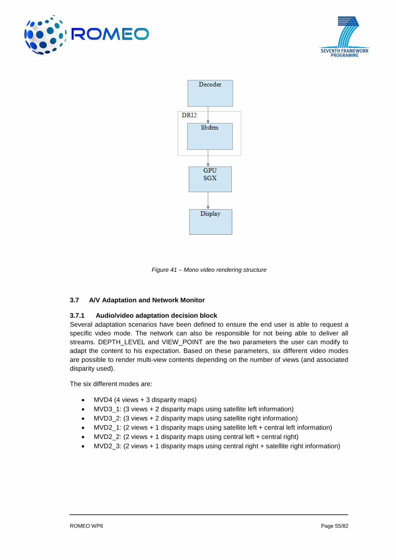
ROMEO WP6 Page 55/82
Figure 41 – Mono video rendering structure
3.7 A/V Adaptation and Network Monitor
3.7.1 Audio/video adaptation decision block
Several adaptation scenarios have been defined to ensure the end user is able to request a
specific video mode. The network can also be responsible for not being able to deliver all
streams. DEPTH_LEVEL and VIEW_POINT are the two parameters the user can modify to
adapt the content to his expectation. Based on these parameters, six different video modes
are possible to render multi-view contents depending on the number of views (and associated
disparity used).
The six different modes are:
MVD4 (4 views + 3 disparity maps)
MVD3_1: (3 views + 2 disparity maps using satellite left information)
MVD3_2: (3 views + 2 disparity maps using satellite right information)
MVD2_1: (2 views + 1 disparity maps using satellite left + central left information)
MVD2_2: (2 views + 1 disparity maps using central left + central right)
MVD2_3: (2 views + 1 disparity maps using central right + satellite right information)

ROMEO WP6 Page 56/82
T3
D3
Disparity
map
satellite left
P
1
P
2
P
3
P
4
P
5
P
6
Video
satellite
left
Video
satellite
right
V
0
V
1
V
2
V
3
V
4
V
5
V
6
V
7
Projected
disparity
maps
Interpolated
views
Estimated
disparity
maps
Video
inputs
Video
central
left
Video
central right
Disparity
map central
left
Disparity
map central
right
Disparity
map
satellite
right
T1 T2T0
D0 D2D1
Figure 41 - MVD2_3 scheme
A more detailed explanation of all available mode is described in deliverable D3.4 as well as in
the future D3.7 (due in M27). The video rendering block is able to adapt the output to the user
requirement choosing the right mode from both DEPTH_LEVEL and VIEW_POINT
parameters. “View selection” block of the GPU core receives from the “decision” block the key
to select the right input to be sent to the interpolation block. The phase of the interpolation is
also sent to the “disparity map projection” block and to the “view interpolation” block.
Another adaptation capability of the system is to address different multi-view displays. The
Alioscopy 42” and the Dimenco 55” are the two multi-view displays selected. The system is
also able to address stereoscopic display in a side-by-side mode (corresponding to a 2-view
display) for the portable application.
3.7.2 Network Monitoring Subsystem
The Network Monitoring Subsystem (NMS) is a software module running at the peer with the
following functions:
Collects peer hardware and software characteristics;
Collects network traffic statistics (packet loss, average delay, jitter, available
bandwidth) for each conection;
Periodically reports the collected data to its parent (it chooses a different parent in
each iteration using a round-robin approach) or to the MTM (in case this is a top level
peer).
Computes the peer stability, a metric defined in ROMEO deliverable D5.1 [1] that
reflects the stability potential of this peer based on previous sessions;
Informs the MTM about detected changes in the network, such as parent
disconnection;
The NMS report contains both the information defined in the NMSReport class (at the server)
and the Specs class (at the peer), see Figure 18 and Figure 42. To save resources and
simplify socket management at the receivers, reports are sent to one of the parents, who then
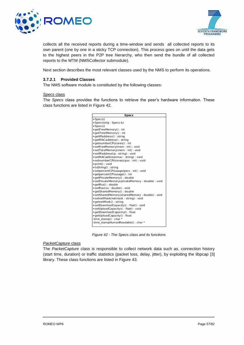
ROMEO WP6 Page 57/82
collects all the received reports during a time-window and sends all collected reports to its
own parent (one by one in a sticky TCP connection). This process goes on until the data gets
to the highest peers in the P2P tree hierarchy, who then send the bundle of all collected
reports to the MTM (NMSCollector submodule).
Next section describes the most relevant classes used by the NMS to perform its operations.
3.7.2.1 Provided Classes
The NMS software module is constituted by the following classes:
Specs class
The Specs class provides the functions to retrieve the peer’s hardware information. These
class functions are listed in Figure 42.
Figure 42 - The Specs class and its functions
PacketCapture class
The PacketCapture class is responsible to collect network data such as, connection history
(start time, duration) or traffic statistics (packet loss, delay, jitter), by exploiting the libpcap [3]
library. These class functions are listed in Figure 43.
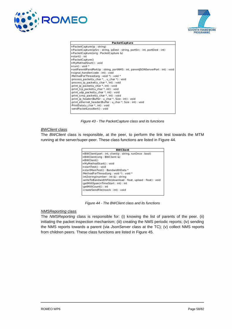
ROMEO WP6 Page 58/82
Figure 43 - The PacketCapture class and its functions
BWClient class
The BWClient class is responsible, at the peer, to perform the link test towards the MTM
running at the server/super-peer. These class functions are listed in Figure 44.
Figure 44 - The BWClient class and its functions
NMSReporting class
The NMSReporting class is responsible for: (i) knowing the list of parents of the peer. (ii)
initiating the packet inspection mechanism; (iii) creating the NMS periodic reports; (iv) sending
the NMS reports towards a parent (via JsonServer class at the TC); (v) collect NMS reports
from children peers. These class functions are listed in Figure 45.
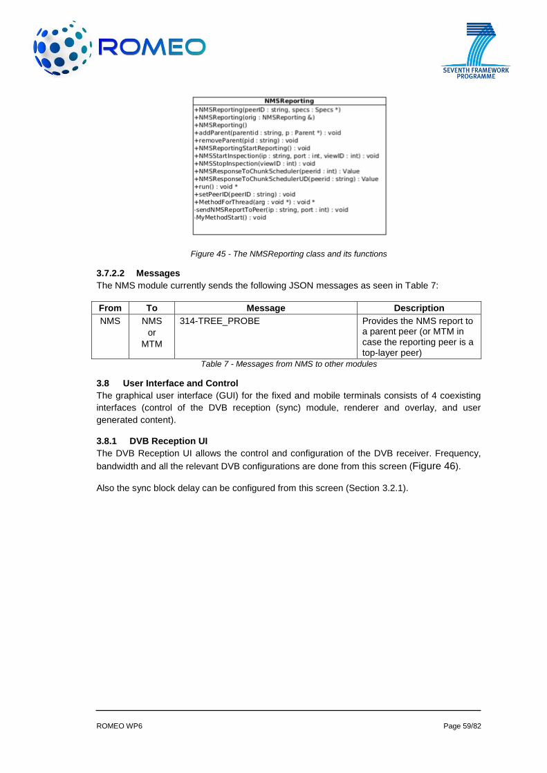
ROMEO WP6 Page 59/82
Figure 45 - The NMSReporting class and its functions
3.7.2.2 Messages
The NMS module currently sends the following JSON messages as seen in Table 7:
From To Message Description
NMS NMS
or
MTM
314-TREE_PROBE Provides the NMS report to a parent peer (or MTM in case the reporting peer is a top-layer peer)
Table 7 - Messages from NMS to other modules
3.8 User Interface and Control
The graphical user interface (GUI) for the fixed and mobile terminals consists of 4 coexisting
interfaces (control of the DVB reception (sync) module, renderer and overlay, and user
generated content).
3.8.1 DVB Reception UI
The DVB Reception UI allows the control and configuration of the DVB receiver. Frequency,
bandwidth and all the relevant DVB configurations are done from this screen (Figure 46).
Also the sync block delay can be configured from this screen (Section 3.2.1).
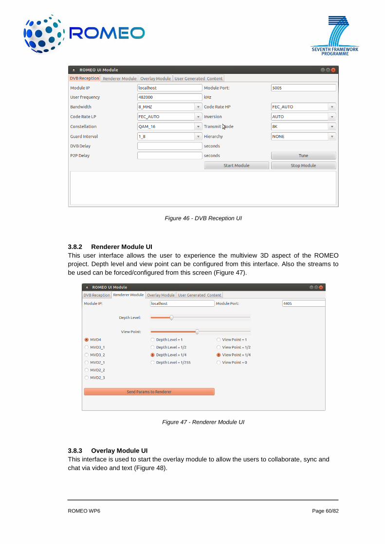
ROMEO WP6 Page 60/82
Figure 46 - DVB Reception UI
3.8.2 Renderer Module UI
This user interface allows the user to experience the multiview 3D aspect of the ROMEO
project. Depth level and view point can be configured from this interface. Also the streams to
be used can be forced/configured from this screen (Figure 47).
Figure 47 - Renderer Module UI
3.8.3 Overlay Module UI
This interface is used to start the overlay module to allow the users to collaborate, sync and
chat via video and text (Figure 48).
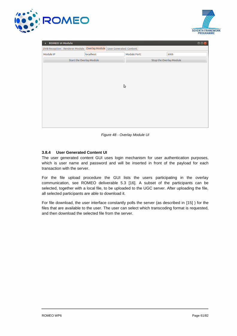
ROMEO WP6 Page 61/82
Figure 48 - Overlay Module UI
3.8.4 User Generated Content UI
The user generated content GUI uses login mechanism for user authentication purposes,
which is user name and password and will be inserted in front of the payload for each
transaction with the server.
For the file upload procedure the GUI lists the users participating in the overlay
communication, see ROMEO deliverable 5.3 [16]. A subset of the participants can be
selected, together with a local file, to be uploaded to the UGC server. After uploading the file,
all selected participants are able to download it.
For file download, the user interface constantly polls the server (as described in [15] ) for the
files that are available to the user. The user can select which transcoding format is requested,
and then download the selected file from the server.
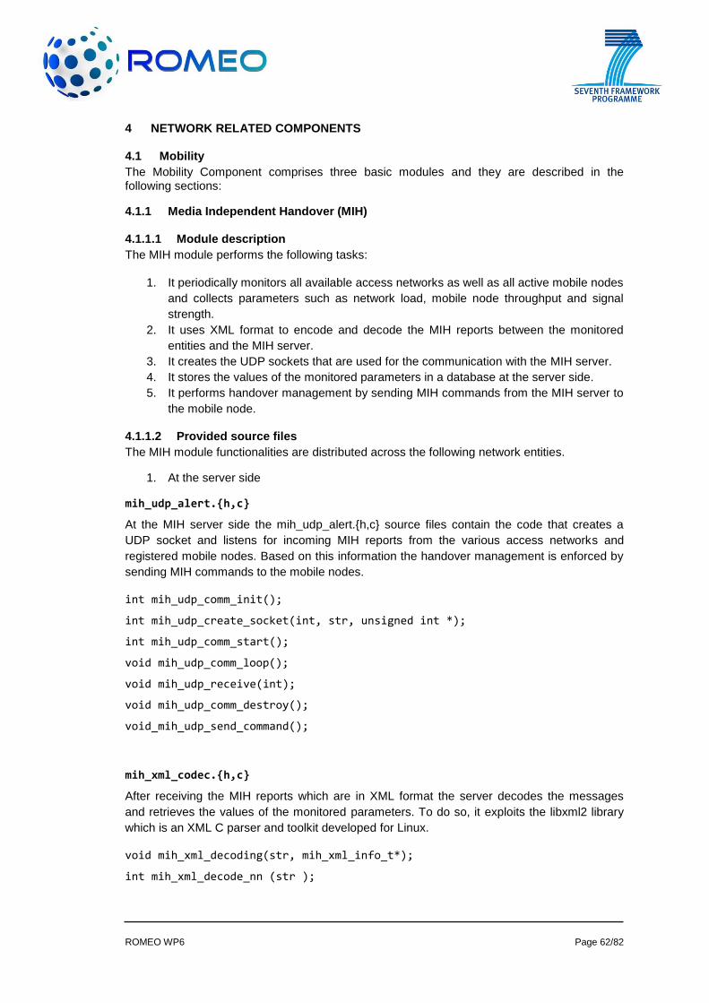
ROMEO WP6 Page 62/82
4 NETWORK RELATED COMPONENTS
4.1 Mobility
The Mobility Component comprises three basic modules and they are described in the following sections:
4.1.1 Media Independent Handover (MIH)
4.1.1.1 Module description
The MIH module performs the following tasks:
1. It periodically monitors all available access networks as well as all active mobile nodes
and collects parameters such as network load, mobile node throughput and signal
strength.
2. It uses XML format to encode and decode the MIH reports between the monitored
entities and the MIH server.
3. It creates the UDP sockets that are used for the communication with the MIH server.
4. It stores the values of the monitored parameters in a database at the server side.
5. It performs handover management by sending MIH commands from the MIH server to
the mobile node.
4.1.1.2 Provided source files
The MIH module functionalities are distributed across the following network entities.
1. At the server side
mih_udp_alert.{h,c}
At the MIH server side the mih_udp_alert.{h,c} source files contain the code that creates a
UDP socket and listens for incoming MIH reports from the various access networks and
registered mobile nodes. Based on this information the handover management is enforced by
sending MIH commands to the mobile nodes.
int mih_udp_comm_init();
int mih_udp_create_socket(int, str, unsigned int *);
int mih_udp_comm_start();
void mih_udp_comm_loop();
void mih_udp_receive(int);
void mih_udp_comm_destroy();
void_mih_udp_send_command();
mih_xml_codec.{h,c}
After receiving the MIH reports which are in XML format the server decodes the messages
and retrieves the values of the monitored parameters. To do so, it exploits the libxml2 library
which is an XML C parser and toolkit developed for Linux.
void mih_xml_decoding(str, mih_xml_info_t*);
int mih_xml_decode_nn (str );
ROMEO WP6 Page 63/82
int mih_informer_xml_encode (xml_writer*, mih_report_t*, MIH_subscription_id_t*);
db_mih.{h,c}
Finally, the server updates the database by performing update operations according to the
monitored entity reports. For that purpose the libdrizzle library was used which implements the
Drizzle and MySQL protocols to support the functionalities of a relational database
management system.
int Server_db_mih_check_subs_client(MIH_subscription_id_t*, str);
int Server_db_mih_ue_insert_info(str, float*, float*, str*, MIH_subscription_id_t*);
int Server_db_mih_ue_update_info(float*, float*, str*, MIH_subscription_id_t, str);
int Server_db_mih_nn_update_info (str*, str*, nn_info_t*);
int Server_db_mih_check_network_node(str*);
int Server_db_mih_nn_insert_info(str*, nn_info_t*, str*);
2. At the Access Network side
mih_monitor.{h,c}
At access network side the relative entities (i.e. EPDG and eNodeB) periodically monitor the
network load.
int mih_network_report();
mih_xml_codec.{h,c}
Then the network load value is passed to the xml encoder to form the MIH report message. As
previously described, the libxml2 library was used for XML encoding
int mih_informer_xml_encode (xml_writer*, mih_report_t*);
mih_udp_comm.{h,c}
Finally, the report is sent to the MIH server. To this end, a UDP socket was created to
communicate with the MIH server.
int mih_timer_udp_alert(void *ptr);
int mih_start_udp ();
static int open_mih_udp_socket(uint16_t ai_family);
static void close_mih_udp_socket(int *socket);
str get_mih_xml (mih_report_t *report);

ROMEO WP6 Page 64/82
int mih_udp_send_msg(void);
int mih_stop_udp (void);
3. At the Mobile Node side:
mih_monitor.{h,c}
Similarly with the access network entities the mobile node reports its related parameters such
as the signal strength and throughput.
typedef mih_report_t (*mm_wlan_mih_report_f)();
mih_report_t mm_wlan_mih_report();
mih_xml_codec.{h,c}
The parameters value are imported into an xml message and sent to the server.
int mih_xml_encode_parameter(xml_writer*xml, mih_report_t*, str );
int mih_informer_xml_encode (xml_writer*, mih_report_t*, MIH_subscription_id_t*);
mih_udp_comm.{h,c}
Finally, the report is sent to the MIH server over UDP transport protocol.
int udp_comm_init();
int udp_comm_start();
void udp_comm_destroy();
4.1.2 Media Aware Proxy
4.1.2.1 Module description
The Media Aware Proxy (MAP) is a transparent user-space module used for low delay filtering
of scalable multiple description video streams. Its functionality extends from the Network Layer
to the Application Layer providing video stream adaptation by taking into account the clients’
wireless network conditions. Therefore based on the load of each access point, MAP is able to
either drop or forward packets that carry specific layers of a stream to the receiving users. The
need for such a middlebox stems from the fact that in a real environment each client must be
able to have a guaranteed QoE. Moreover, the need for transparency derives from the fact
that each new platform should provide backwards compatibility in order to be able to work with
existing networks. So in the current implemented module there is no need to modify neither
the client’s feedback channel nor the streamer’s signaling channel.
4.1.2.2 Provided source files
media_aware_proxy.{h,c}
The “media_aware_proxy” module provides the main method which is responsible for the
initialization and invoking of all MAP’s modules.
ROMEO WP6 Page 65/82
int main(int argc, char **argv)
void ctrlC(int sig);
void close_map(const char error_message[100]);
void showUsage();
map_thread.{h,c}
The “map_thread” is the most important module since it is responsible for the traffic
management.
It binds to the “Netlink” socket and receives IP/UDP/P2P packets by exploiting the
libraries of “ip_queue” module and “Netfilter” mechanism.
It identifies the packet address by parsing the UDP/IP headers.
It identifies the video information by parsing the P2P header through “p2pParser”
module.
It identifies the client through a comparison of the packet’s destination address and
the “key_id” field of the mih_clients_mobility table included in MIH database
It either forwards or drops the packets based on the “check_p2p_packet” method,
which uses the decision of the “adte_thread” module.
void *media_aware_proxy(void*);
int check_p2p_packet(client_info*);
int initialize_ip_queue();
int create_map_thread();
void destroy_map_thread();
void queue_error(struct ipq_handle*);
adte_thread.{h,c}
The “adte_thread” module is responsible for the correct decision of which
views/layers/descriptions can safely be received by each client.
It uses the “client_info” provided by “global_variables” module in order to identify the
data rate for each client’s receiving view/description/layer.
It uses the “networks_info” structures provided by “global_variables” module in order
to identify the load of each access network (Wi-Fi, LTE).
It invokes the “update_console” method of the “console” module in order to update
the console with the information (client’s traffic, access point statistics) of the last
second.
It compares the load of each access point with the maximum acceptable load and it
calculates the available bandwidth for each client.
It allows the forwarding, only of those layers, that fit to the available bandwidth. The
prioritization of each description is predefined with the descriptions of the stereo pair
being more important than the side cameras as well as the base layers of the side
cameras being more important than the corresponding enhancement layers.
ROMEO WP6 Page 66/82
void *adte_thread(void*);
void culculate_clients_available_bw();
void update_clients_available_bw(const char*,float);
void clients_adte_decision();
void calculate_client_data_rate_of_layers(client_info*);
void execute_adte(client_info*);
void reset_client_statistics(client_info*);
int create_adte_thread();
void destroy_adte_thread();
database_thread.{h,c}
The “database_thread” module is responsible for the connection to the MIH database provided
by the MIH server.
It updates the information of each connected client (id, wireless type, signal,
throughput, IP address, subscription id) from the “mih_clients_mobility” table
It retrieves the statistics for all monitored access networks (network id, type, IP
address, network load) stored at the “mih_network” table.
void *update_from_db_thread(void*);
int connect_to_db();
int create_db_thread();
void destroy_db_thread();
console.{h,c}
The “console.c” module exploits the “ncurses” library in order to provide a legible overview of
the MAP statistics collected by the “map_thread”, “adte_thread” as well as “database_thread”
module.
void *update_console();
void init_wins(WINDOW**, int);
void write_to_wins(WINDOW*, WINDOW*, WINDOW*, WINDOW*);
void win_show(WINDOW*, const char*, int);
int initialize_console();
void destroy_console();
ip_udp_header.{h,c}
The “ip_udp_headers” module implements the IP and UDP structures as well as the
aforementioned method which checks if the transport protocol is supported by the application.
This auxiliary module is invoked by the “p2pParser” module in order to parse the IP/UDP
headers of each packet.
ROMEO WP6 Page 67/82
const char* get_transport_protocol(__u8 number);
p2pParser.{h,c}
The “p2pParser” implements all the methods of “p2pParser” provided by P2PTransmitter in
order to parse the P2P header of each packet. Moreover, it implements the “fast_p2p_parse”
which is responsible for the IP/UDP/P2P header parsing of a packet.
int initialize_p2p_parser();
void destroy_p2p_parser();
int fast_p2p_parse(struct ipq_handle*, ipq_packet_msg_t*, client_info*);
uint64_t getPTS(P2PHeader*);
short getChunkId(P2PHeader*);
short GetViewId(P2PHeader*);
short GetDescriptiorId(P2PHeader*);
short getPID(P2PHeader*);
short getContentID(P2PHeader*);
short getLayerID(P2PHeader*);
short getPriority(P2PHeader*);
short getAudioIndicator(P2PHeader*);
short getMetadataFlag(P2PHeader*);
int SHORT_little_endian_TO_big_endian(int);
int INT_little_endian_TO_big_endian(int);
char* INT_little_endian_TO_big_endian_string_ip(int);
xml_parser.{h,c}
The “xml_parser” module exploits the libxml2 library in order to parse the “map_config.xml” file
which contains information about the initialization of MAP.
int initialize_xml_parser(const char* file_name);
void destroy_xml_parser();
xmlNodePtr xml_find_element(const char *node_name,xmlNodePtr node);
int xml_decoding();
parameters_info* get_parameters();
log_files.{h,c}
The “log_file” module provides logging methods to each module.
void initialize_p2p_log_file(const char*);
void print_to_p2p_log_file();
void print_ok();
ROMEO WP6 Page 68/82
void print_dropped();
void close_file();
void initialize_delay_log_file(const char*);
void write_time_to_delay_file(long, long int);
void close_delay_file();
void initialize_db_log_file(const char*);
void write_client_info_to_db_file(client_info*);
void close_db_file();
void initialize_adte_log_file(const char*);
void write_to_adte_file(const char*);
void close_adte_file();
global_variables.{h,c}
The “global_variables” module holds all the definition, structures, variables, linked lists shared
among the different modules. There are a variety of methods which enable the creation,
update, search and deletion of a client’s node in the linked list “client_info”.
int initialize_global_variables();
void destroy_global_variables();
void set_error_occurred();
void initialize_new_mutex(pthread_mutex_t);
void destroy_old_mutex(pthread_mutex_t);
client_info* new_client(int);
client_info* search_client_by_ip(char);
client_info* search_client_by_id(int);
int update_client(client_info*, MYSQL_ROW);
void clear_client(client_info*);
void delete_client(void);
void destroy_linked_list();
void initialize_global_log_file(const char*);
void write_global_log_file(const char*);
void close_global_log_file();
4.1.3 Proxy Mobile IP
4.1.3.1 Module description
Proxy Mobile IP is responsible for allowing mobile nodes to move from one access network to another while maintaining their IP connectivity and without requiring their involvement in the overall process.
ROMEO WP6 Page 69/82
1. It detects the movement of mobile node in order to be aware of each node’s current
position by monitoring link layer operations.
2. It implements the exchange of signalling messages between the Mobile Access
Gateway (MAG) and the Local Mobility Anchor (LMA) that enables the creation and
maintenance of a binding between the mobile node's home address(es) and its
serving access network.
3. It creates bidirectional tunnels between the LMA and the serving MAG in order to
deliver packets that are destined to the mobile node.
4.1.3.2 Provided source files
lma.{h,c}
LMA is the home agent for the mobile node in a Proxy Mobile IP domain. It is the topological anchor point for the mobile node's home network address(es) and is also the entity that manages the mobile node's binding state. The main module of the LMA component contains the logic for handing the requests (Proxy Binding Update message - PBU) coming from the MAGs of the various Access Network Gateways. It parses the PBUs and if it is an attachment or detachment it updates the routing tables and establishes or closes respectively the one end of the bi-directional tunnel to the requesting MAG. If it is an update it refreshes the life time of the respective Binding Cache entry. Finally it responds with a Proxy Binding Acknowledgement (PBA) message to the MAG. lma_procedure_result_e lma_attach(gw_binding_t*, gw_binding_apn_t*);
lma_procedure_result_e lma_detach(gw_binding_t*, gw_binding_apn_t*);
lma_procedure_result_e lma_handover(gw_binding_t*, gw_binding_apn_t*);
lma_procedure_result_e lma_refresh(gw_binding_t*, gw_binding_apn_t*, ip_address);
lma_procedure_result_e lma_detach_during_handover(gw_binding_t*, gw_binding_apn_t*);
lma_procedure_result_e lma_attach_during_handover(gw_binding_t*, gw_binding_apn_t*);
int lma_del_routes(gw_binding_t*);
int lma_del_routes_apn(gw_binding_t*, gw_binding_apn_t*);
int lma_add_routes(gw_binding_t*);
int lma_add_routes_apn(gw_binding_t*, gw_binding_apn_t*);
int lma_init_routes();
void lma_first_packet_callback(gw_binding_t*, gw_binding_apn_t *);
int lma_del_leftover_teid_route(void*);
mag.{h,c}
The main module of the MAG component contains the logic for detecting the mobile node’s attachments and detachments and then informing the LMA for these events by sending a Proxy Binding Update (PBU) message. Additionally it sets up its endpoint of the bi-directional tunnel to LMA upon receiving the PBA message.
int mag_init_routing_table();
ROMEO WP6 Page 70/82
int mag_del_routes(gw_binding_t*);
int mag_del_routes_apn(gw_binding_t*,gw_binding_apn_t*);
int mag_add_routes(gw_binding_t*);
int mag_add_routes_apn(gw_binding_t*,gw_binding_apn_t*);
int mag_initial(gw_binding_t*, gw_binding_apn_t*, uint8_t, ip_address, ip_address);
int mag_refreshing(gw_binding_t*,gw_binding_apn_t*, uint8_t, ip_address, ip_address);
int mag_confirmed();
int mag_waiting_for_dhcp();
int mag_deleting(gw_binding_t*, gw_binding_apn_t*, uint8_t);
int mag_handover(gw_binding_t*, gw_binding_apn_t*);
int mag_reply_to_source(mag_callback_operation_e, gw_binding_t*, gw_binding_apn_t*);
4.2 Virtualisation
4.2.1 Description and current status
The development carried out in the virtualisation platform involves shifting the layer 3
functionalities, currently tackled by the Residential Gateway (RGW), to the operator premises
aiming a layer 2 access network until the residential environment. The configuration of the
BRAS, ONT, OLT and MAN and the development and integration of the DHCP server was
reported in [18] .
The status of the virtualisation testbed up to year two, regarding the developments and
configurations performed within the network elements that compose the access network is
described in following sections:
4.2.1.1 Development of the Configuration Portal
The configuration portal is the web-based tool that allows end users to configure their
virtualized router functionalities like the DHCP options, the IP addressing scheme, the port-
forwarding configuration, etc. In addition, the Configuration Portal has the ability to manually
enforce the flow prioritization in order to demonstrate the QoS enforcement at access network
level.
The configuration portal has the following capabilities:
To know the public IP address assigned to the virtual router
To know the local network information (the IP subnet, the network mask, the gateway,
the broadcast address and the primary and secondary DNSs)
To know the IP addresses that are reserved to be assigned with the DHCP server
To know the IP address and MAC address associations (same devices will obtain the
same IP address from the DHCP server) and the possibility of delete the associations
To know the current assigned IP addresses and the MAC address of the device
To manually configure the IP address that will be assigned to an specific device
(identified by its MAC address)
ROMEO WP6 Page 71/82
To define and consult port-forwarding rules, in order to forward an incoming TCP or
UDP flow (identified by the used port) to an internal device
To manually define an incoming flow prioritization
4.2.1.2 Development of the Network API
The Network API is an application-programming interface that simplifies the communication of
third-party services with the PCRF owned by the network operators. The point of the Network
API is to offer a simple HTTP-based interface to the upper services (instead of complicated
diameter-based protocol as Rx, defined by the 3GPP) and to hide the network complexity.
The Network API is running over Apache and is based in Python. The Super Peer will send
the information to the Network API using an HTTP POST message using the endpoint
“http://<network_api_address>/api/set-perfil”. The parameters of that function are:
Profile: The name of the physical profile applied to the end-user physical line
User: Identification of the end-user on the PCRF.
DestIP: IP address of the SuperPeer
DestPort: Source port of the flow to be prioritised
OrigPort: Destination port of the flow to be prioritosed
4.2.1.3 Configuration of the Policy and Charging Rules Function (PCRF)
The PCRF is a 3GPP standardized function responsible for defining the QoS rules that will be
applied to a particular user. It will receive from the Super Peer though the Network API the
physical parameters that identify a certain user and communicates with the Policy and
Charging Enforcement Function (PCEF, that is hosted in the NATIE) in order to enforce the
rules in the access network.
The PCRF is integrated with the Network API by using the Rx interface and also with the
NATIE (BRAS) by using the Gx interface. There is a user identifier configured on the PCRF
with a real fiber access line, placed on TID premises at Madrid.
4.2.1.4 Configuration of the Policy and Charging Enforcement Function (PCEF)
The PCEF function is the one in charge to enforce the QoS policies applied from the PCRF
and it is embedded within the BRAS (the NATIE).
There is a predefined profile on the NATIE that priotizes a flow over background traffic. The
PCRF will send to the PCEF the flow definition (IP addresses and transport ports) in order to
get the required QoS on the ROMEO flow.
4.2.2 Future work
The next steps that need to be taken in the virtualisation platform are the development of the
Virtual Software Execution Environment (VSEE), which has just started, that will enable the
hosting of the execution capabilities that currently run on the RGW (e.g. UPnP control point) or
other ROMEO capabilities that will be identified as potential candidates to be virtualized on the
network too.
4.3 Internet Resource and Admission Control System
As it is depicted in Figure 49, the Internet Resource and Admission Control Subsystem
(IRACS) is a set of software modules composed of a Resource and Admission Manager
(RAM) component and a Resource Controller (RC) component with the following functions:
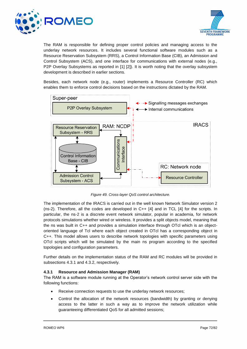
ROMEO WP6 Page 72/82
The RAM is responsible for defining proper control policies and managing access to the
underlay network resources. It includes several functional software modules such as a
Resource Reservation Subsystem (RRS), a Control Information Base (CIB), an Admission and
Control Subsystem (ACS), and one interface for communications with external nodes (e.g.,
P2P Overlay Subsystems as reported in [1] [2]). It is worth noting that the overlay subsystem
development is described in earlier sections.
Besides, each network node (e.g., router) implements a Resource Controller (RC) which
enables them to enforce control decisions based on the instructions dictated by the RAM.
Figure 49. Cross-layer QoS control architecture.
The implementation of the IRACS is carried out in the well known Network Simulator version 2
(ns-2). Therefore, all the codes are developed in C++ [4] and in TCL [4] for the scripts. In
particular, the ns-2 is a discrete event network simulator, popular in academia, for network
protocols simulations whether wired or wireless. It provides a split objects model, meaning that
the ns was built in C++ and provides a simulation interface through OTcl which is an object-
oriented language of Tcl where each object created in OTcl has a corresponding object in
C++. This model allows users to describe network topologies with specific parameters using
OTcl scripts which will be simulated by the main ns program according to the specified
topologies and configuration parameters.
Further details on the implementation status of the RAM and RC modules will be provided in
subsections 4.3.1 and 4.3.2, respectively.
4.3.1 Resource and Admission Manager (RAM)
The RAM is a software module running at the Operator’s network control server side with the
following functions:
Receive connection requests to use the underlay network resources;
Control the allocation of the network resources (bandwidth) by granting or denying
access to the latter in such a way as to improve the network utilization while
guaranteeing differentiated QoS for all admitted sessions;
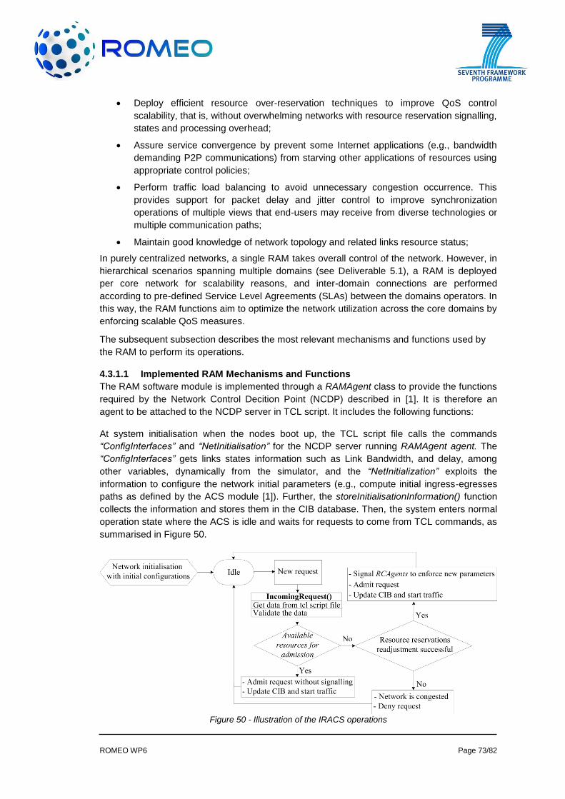
ROMEO WP6 Page 73/82
Deploy efficient resource over-reservation techniques to improve QoS control
scalability, that is, without overwhelming networks with resource reservation signalling,
states and processing overhead;
Assure service convergence by prevent some Internet applications (e.g., bandwidth
demanding P2P communications) from starving other applications of resources using
appropriate control policies;
Perform traffic load balancing to avoid unnecessary congestion occurrence. This
provides support for packet delay and jitter control to improve synchronization
operations of multiple views that end-users may receive from diverse technologies or
multiple communication paths;
Maintain good knowledge of network topology and related links resource status;
In purely centralized networks, a single RAM takes overall control of the network. However, in
hierarchical scenarios spanning multiple domains (see Deliverable 5.1), a RAM is deployed
per core network for scalability reasons, and inter-domain connections are performed
according to pre-defined Service Level Agreements (SLAs) between the domains operators. In
this way, the RAM functions aim to optimize the network utilization across the core domains by
enforcing scalable QoS measures.
The subsequent subsection describes the most relevant mechanisms and functions used by
the RAM to perform its operations.
4.3.1.1 Implemented RAM Mechanisms and Functions
The RAM software module is implemented through a RAMAgent class to provide the functions
required by the Network Control Decition Point (NCDP) described in [1]. It is therefore an
agent to be attached to the NCDP server in TCL script. It includes the following functions:
At system initialisation when the nodes boot up, the TCL script file calls the commands
“ConfigInterfaces” and “NetInitialisation” for the NCDP server running RAMAgent agent. The
“ConfigInterfaces” gets links states information such as Link Bandwidth, and delay, among
other variables, dynamically from the simulator, and the “NetInitialization” exploits the
information to configure the network initial parameters (e.g., compute initial ingress-egresses
paths as defined by the ACS module [1]). Further, the storeInitialisationInformation() function
collects the information and stores them in the CIB database. Then, the system enters normal
operation state where the ACS is idle and waits for requests to come from TCL commands, as
summarised in Figure 50.
Figure 50 - Illustration of the IRACS operations
ROMEO WP6 Page 74/82
When a new service request comes, the function IncomingRequest() is called to parse and to
validate the variables passed through the TCL command (e.g., avoid parsing negative CoS or
bandwidth values, check uniqueness of flows and session IDs). After that, the ACS takes into
account the requested amount of bandwidth and the available bandwidth in the network for the
admission decisions. The ACS always selects the best paths to accommodate an incoming
flow, this procedure may involve several steps depending on the network resource conditions
and the service demand as in the following:
i) If there is sufficient available bandwidth on existing paths for the requested
service, the ACS selects the path which has the most available resources and
accommodates the request. After that, the updateCIB() function is called to update
the CIB information accordingly (e.g., requested Class of Service (CoS),
bandwidth, session IDs, flows IDs, protocol IDs, ports IDs, and paths information).
Then, the traffic is generated in the simulation by calling the function
CreateTraffic() and the ACS system returns to idle state to be able to pasre
another request upon need.
ii) In case the requested bandwidth is above the available bandwidth in the network,
ACS triggers the RRS module and the latter calls ReservationComputation(path,
requested_bandwidth,CoS) function to define new resource reservation
parameters for the existing network paths. The resource reservation readjustment
algorithm is described in [6]. If the reservation parameters are readjusted
successfully on a potential path, that is, the requested CoS is increased with
sufficient available resources from other existing CoSs on a path, the nodes on
the concerned path are signaled where the RC module described later in
subsection 4.3.2 is responsible for enforcing the new parameters defined for them
along the path. Then, ACS admits the pending request, the CIB database is
updated accordingly and the traffic is generated in the simulation environment as
we described earlier. In this way, the reservation parameters are defined and
readjusted dynamically in a way to prevent CoS starvation or unnecessary waste
of resources while the QoS control signalling frequency is reduced for scalability.
iii) In the situation where the network is congested and requested bandwidth is above
the total unused resource on all paths, the ACS denies the incoming to prevent
control performance degradation.
iv) When a running session terminates, the ACS stops the related traffic and the CIB
database is updated accordingly by using the updateCIB() function.
In order to enable operations over multiple domains, an interDomainOperations() interface is
defined in RAMAgent to allow interactions between the RAM and external nodes such as other
RAMs, super-peer, a signle peer or the ROMEO server. Also, the ACS system implements
recv() and send() functions in order to effectively receive and to send commands and
messages while being able to issue commands and messages with control instructions
forwards the RCAgents inside the network. The mechanisms and functions implemented by
the RC module to allow a proper coordination with the RAM to enforce control decisions and
policies specified by the latter are described in subsequent subsection.
4.3.2 Resource Controller (RC)
The RC is a software module running mainly in the routers at the ISP network with the
following functions:
Deploy elementary transport functions to enable UDP port recognition (routers are
permanently listening on a specific UDP port) or IP Router Alert Option (RAO) [1] on
nodes to properly intercept, interpret and process control messages.
ROMEO WP6 Page 75/82
Receive resource reservation and multicast tree creation instructions from the RAM
and properly enforce them on the nodes;
Interact with Resource Management Functions (RMF) [1] to properly configure
schedulers on nodes [1], thus ensuring that each CoS receives the amount of
bandwidth allocated to it to provide QoS-aware data transport across the network;
Assure basic network functions such as packets forwarding and routing;
Exploit legacy control databases such as, but are not limited to, the Management
Information Base (MIB), Routing Information Base (RIB) or multicast Routing
Information Base (MRIB) and Forwarding Information Base (FIB), according to the
control instructions received from the RAM;
Learn inter-domain routing information from the traditional Border Gateway Protocol
(BGP) [1] for proper communications between various network domains and
operators.
4.3.2.1 Implemented RC Mechanisms and Functions
The RC software module is implemented by means of an RCAgent class to provide the
functions required by the network nodes (e.g., routers) described in [1]. It is an agent that must
be attached to each node in TCL script and includes the following functions:
In the TCL script, the command “ConfigInterfaces” must be called at system initialisation for all
RCAgents in the network so every node collects the links states information and configures its
local interfaces CoSs and related initial reservations parameters. The initial reservation
parameters are computed by using the function CoS_initial_Reservation(interface) that takes
one interface as input parameter according to the policies defined in the algorithm described in
[6]. Then, the computed values are enforced in the simulator environment upon successful
computation by means of an addQueueWeights command. This command receives each CoS
with the related weight p, which is a percentage of the link bandwidth to be assigned for the
CoS.
Besides, the RCAgent also implement the recv() and send() functions to be able to intercept
commands and messages conveyed to it or to forward or send messages, respectively. Upon
receiving a message (e.g., from RAM), the RCAgent is able to interpret the information and
instructions conveyed by calling a parseInformation() function. In addition, a
pathReservationEnforcement(PATH, Links_Parameter_s) function is implemented by the
RCAgent in order to properly enforce resource reservation parameters on nodes along
communications paths to ensure that each CoS receives the bandwidth destined to it.
ROMEO WP6 Page 76/82
5 CONCLUSION
This deliverable provides a detailed report on the development status of ROMEO system
components at the end of the second year of the project. The document divides the ROMEO
components into two main groups: Server components and Peer components and focuses on
each part separately. Since most of the development tasks of the project are near the end, this
report includes almost complete descriptions for most of the modules.
Besides being used as a development reference for the whole system, this deliverable will
also provide an opportunity to check the components’ timelines for integrated solution which is
provided in detail in the deliverable D6.3 - Second report on system components development
plan.

ROMEO WP6 Page 77/82
6 REFERENCES
[1] ROMEO Deliverable 5.1, “Interim report on 3D media networking and synchronisation of networks”; 2012.
[2] ROMEO Deliverable 2.2, “Definition of the initial reference end-to-end system architecture and the key system components”; 2011.
[3] The libpcap project. url: http://sourceforge.net/projects/libpcap/
[4] C++: Programming Language, url: http://www.cplusplus.com.
[5] TCL: Script Language, url: http://www.tcl.tk/
[6] Logota E, Neto A, Sargento S (2010) COR: an Efficient Class-based Resource Over-pRovisioning Mechanism for Future Networks. IEEE Symposium on Computers and Communications (ISCC), Riccione, 22-25 Jun 2010.
[7] ROMEO Deliverable D4.1 ‘Specifications of the encoder/decoder software for the MD-MVD and the ABS spatial audio codec’; September 2012.
[8] ETSI EN 300 468 V1.13.1: Digital Video Broadcasting (DVB); Specification for Service Information (SI) in DVB systems (2012-08).
[9] ISO/IEC 13818-1: "Information technology - Generic coding of moving pictures and associated audio information: Systems".
[10] RFC 1945: Hypertext Transfer Protocol -- HTTP/1.0
[11] RFC 2818: HTTP Over TLS.
[12] RFC 3986: Uniform Resource Identifier (URI): Generic Syntax.
[13] ISO/IEC 14496-10-MPEG-4 Part 10 (ITU-T H.264).
[14] ISO/IEC 14496-10-MPEG-4 Part 10 Annex G Scalable Video Coding (SVC).
[15] ROMEO Deliverable 5.4, “Report on User Generated Content Provisioning”; 2013.
[16] ROMEO Deliverable 5.3, “Report on real-time Audio-Visual communication overlay for remote users”; 2013
[17] ROMEO Deliverable 2.3, “Interim reference system architecture report”; 2012
[18] ROMEO Deliverable 6.2, “First report on server, peer, user terminal, security and content registration modules development”; 2012
[19] Joint Scalable Video Model (JSVM) access details:
http://www.hhi.fraunhofer.de/de/kompetenzfelder/image-processing/research-groups/image-video-coding/svc-extension-of-h264avc/jsvm-reference-software.html
ROMEO WP6 Page 78/82
APPENDIX A: GLOSSARY OF ABBREVIATIONS
A
AAA Authentication, Authorization and Accounting
ACS Admission and Control Subsystem
ADL Audio Description Language
AAC Advanced Audio Coding
ADTE Adaptation Decision Taking Engine
AGC Automatic Gain Control
AMF Action Message Protocol
AP Access Point
ARC Arcelik A.S.
ARM Advanced RISC Machines
ASIO Audio Stream Input/Output
A/V Audio / Video
AVC Advanced Video Coding
B
BCC Binaural Cue Coding
BGRP Border Gateway Reservation Protocol
BRAS Broadband Remote Access Server
BRIR Binaural Room Impulse Responses
BRS Binaural Room Synthesis
BRTF Binaural Room Transfer Functions
C
CDN Content Delivery Networks
CN Correspondent Node
CoA Care of Address
CoS Class of Services
CPE Customer Premises Equipment
CPU Central Processing Unit
CS Chunk Selection
CSRC Contributing Source
D
D/A Digital to Analog
DHCP Dynamic Host Configuration Protocol
DON Decoding Order Number
DoW Description of Work
DVB Digital Video Broadcast
DVR Digital Video Recorder
F
FA Foreign Agent
FEC Forward Error Correction
FFT Fast Fourier Transform
ROMEO WP6 Page 79/82
FM Frequency modulation
FMIP Fast Mobile Internet Protocol
Fps Frames Per Second
FTP File Transfer Protocol
FU Fragmentation Unit
G
GBCE Global Brightness Contrast Enhancement
GM General Meeting
GPON Gigabit Passive Optical Network
GPS Global Positioning System
GPU Graphics Processing Unit
GUI Graphical User Interface
H
HA Home agent
HD High Definition
HDMI High-Definition Multimedia Interface
HLOS High Level Operating System
HMIP Hierarchical Mobile IP
HRTF Head Related Transfer Function
HoA Home Address
I
ICC Inter-Channel Coherence
ICLD Inter-Channel Level Difference
ICTD Inter-Channel Time Difference
IETF Internal Engineering Task Force
IFFT Inverse Fast Fourier Transform
IGMP Internet Group Management Protocol
ILD Inter-aural Level Differences
IP Internet Protocol
IPR Intellectual Property Rights
IPTV Internet Protocol Television
IRT Institut für Rundfunktechnik GmbH
IT Instituto de Telecomunicações
ITD Inter-aural Time Differences
J
JSON-RPC JavaScript Object Notation-Remote Procedure Call
L
LCD Liquid Crystal Display
LFE Low Frequency Enhancement
LMA Local Mobility Anchor
LTE Long Term Evolution
LVDS Low Voltage Differential Signalling
M
MAC Media Access Control
MAG Mobility Access Gateway
ROMEO WP6 Page 80/82
MANE Media Aware Network Element
MANET Mobile Ad-Hoc Network
MAP Mobility Anchor Point
MARA Multi-user Aggregated Resource Allocation
MCX Micro Coaxial
MDC Multiple Description Coding
MDCT Modified Discrete Cosine Transform
MD-SMVD Multiple Description Scalable Multi-view Video plus Depth
MICS Media Independent Command Service
MIES Media Independent Event Service
MIH Media Independent Handover
MIIS Media Independent Information Service
MIP Mobile Internet Protocol
MISO Multiple Input Single Output
MM Mobility Management
MMS MM Solutions AD
MN Mobile Network
MPEG Moving Pictures Experts Group
MPLS Multiprotocol Label Switching
MST Multi-Session Transmission
MT Mobile Terminal
MTAP Multi-Time Aggregation Packet
MTD Mobile Terminal Display
MULSYS MulSys Limited
MVC Multi View Coding
N
NAL Network Abstraction Layer
NAT Network Address Translation
NEM Networked Electronic Media
NGN Next Generation Networks
NMS Network Monitoring Subsystem
NS-2 Network Simulator 2
O
OFDM Orthogonal Frequency Division Multiplexing
OLT Optical Line Terminal
OMAP Open Multimedia Application Platform
ONT Optical Network Terminal
P
P2P Peer-to-Peer
PAPR Peak to Average Power Ratio
PC Personal Computer
PHY Physical
PLP Physical Layer Pipe
PMIP Proxy Mobile Internet Protocol
PoA Point of Attachment
ROMEO WP6 Page 81/82
PoP Package on Package
POTS Plain Old Telephone Service
PPP Point-to-Point Protocol
PPSP Peer-to-Peer Streaming Protocol
PSW Priority Sliding Window
R
R-OTT Reverse One-To-Two
R&S Rohde & Schwarz GmbH & Co. KG
RAT Remote Access Technology
RF Radio Frequency
RGB Red Green Blue
RISC Reduced Instruction Set Computer
RMI Remote Method Invocation
RO Route Optimization
RRP Return Routability Protocol
RSVP Resource ReServation Protocol
RTCP-XR Real Time Control Protocol Extended Report
RTMP Real Time Message Protocol
RTP Real-time Transport Protocol
RTSP Real Time Streaming Protocol
Q
QAM Quadrature Amplitude Modulation
QAT Quality Assurance Team
QoE Quality of Experience
QoS Quality of Service
S
SAC Spatial Audio Coding
SD Standard Definition
SDP Session Description Protocol
segSNR segmental Signal-to-Noise Ratio
SEI Supplemental Enhancement Information
SIDSP Simple Inter-Domain QoS Signalling Protocol
SMVD Scalable Multi-view Video plus Depth
SoC System on Chip
SSRC Synchronisation Source
SST Single Session Transmission
STAP Single-Time Aggregation Packet
SVC Scalable Video Coding
T
TB Topology Builder
TC Topology Controller
TEC Technicolor R&D France
TFT Thin Film Transistor
TID Telefónica I+D
TTA Türk Telekomünikasyon A.Ş.
ROMEO WP6 Page 82/82
TS Transport Stream
U
UDP User Datagram Protocol
UHF Ultra High Frequency
UP University of Patras
US University of Surrey
V
VAS Value Added Service
VITEC VITEC Multimedia
VoD Video On Demand
W
Wi-Fi Wireless Fidelity
WFS Wave Field Synthesis
WG Working Group
WP Work Package
WVGA Wide Video Graphics Array
WXGA Wide eXtended Graphics Array
X
XGA eXtended Graphics Array
Numbers
4G 4th Generation
![Privacy and Mechanism Designaaroth/Papers/PrivacyMDSurvey.pdf · 2013-06-06 · private mechanism: the exponential mechanism of [MT07]. De nition 2.2. The exponential mechanism is](https://img.pdfslide.net/doc/110x75/5f0baa9c7e708231d4319fea/privacy-and-mechanism-design-aarothpapers-2013-06-06-private-mechanism-the.jpg)