Embed Size (px)
Citation preview
10/19/20
1
} Ammonia Refrigerant Pressure Vessel Design
ByRamesh Paranjpey
Fellow Life Member ASHRAEASHRAE 50-year Distinguished Service Award-2020
Chairman ISHRAE Technical Group
130-10-2020
1
Pressure vessels used in Ammonia Refrigeration systems
230-10-2020
1. Oil Separators after compressor & before condenser2. High pressure Liquid Receiver for ammonia storage3. Inter-stage cooler-open type- for two stage system4. Inter-stage cooler –with closed coil –for two stage
system5. Low pressure Ammonia storage vessel- in forced feed
pump circulation system ( L.P. Vessel)6. Surge drum mounted on shell & tube flooded chillers7. Accumulators for gravity flooded cold storage- air
coolers, PHE, ice bank etc.8. Knock out drums to protect compressors from liquid9. Oil Pots for oil draining
2
1. 21 kg/cm2 g for water cooled Applications-AAR standard
2. 27kg/cm2 g for air cooled-AAR standard
3. Design Pressure-+170C above wet Bulb for Water Cooled min. –EN/ISO standard
4. +170C above Dry Bulb for Air Cooled Minimum- EN/ISO standardI Prefer Designing for both High and low stage Vessels same pressures to Reduce Ammonia Charge. Ammonia can be then stored in L.P. vessel & there is no need to
pump down if one wants to stop the plant.30-10-2020
3
3
1. ANSI/IIAR-2 20142. AAR-1 standard 3. ANSI/ASHRAE-15 20134. ASME B31.5 20135. ASME Sect V III-Div. 16. TEMA7. ISO-51498. EN 3789. IS 665- latest10. OSHA11. BIS-2825
30-10-2020
4
1.Use Boiler Quality plates for Fabrication- IS2002
Gr 2A or SA516/Gr.70 –SA517 Gr-60/70 plates & refer
AAR- 1 standard. Do not use Structural steel IS-2062
2. Use proper Thickness of plate as per TEMA standards
Consider joint efficiency as 0.7 if no radiography is done
Add corrosion allowance 0f 1.6mm in calculated
thickness.
3. Fabrication as per IS 2825 or ASME sec. VIII-Div. 1
or EC/97/23 30-10-20205
5
} MOC: SA 516 Gr. 70-Allowable stress 17500 psi(ASME CODE/BIS2825)
} Vessel Size say: 30” diameter x 12 ft long} Calculations Based on ASME Sec VIII Div. 1} t =PxR/(SE-0.6P)} Where,} t = minimum required thickness (inch.)} P = Internal design pressure in (psi)} R = inside Radius } S= Allowable Stress for material } E=Joint Efficiency} E= 0.70 DP Test only} E=0.85 10% Radiography} E=1.0 100% Radiography
30-10-20206
6
10/19/20
2
ITEM Value Unit Value UnitP 300 Psi 21.1 Kg/cm2
R 15 Inch 381 MmS 17500 Psi 1230.4 Kg/cm2
E 0.7 % 0.7 %
t= 300Px15R/(17500SxE0.7-0.6xP300)t= 4500/(12250-180)12070= 0.37 inch or 9.47 mmAdd corrosion allowance of 1.6 mmThickness required is-11.07 mmUse next Available size as 12mm thick plate
30-10-2020
7
Vessel Diameter-inch
Thickness-mm516 Gr.70
Dish end Thickness-mm
24 10 1030 12 1236 14 1442 16 1648 18 18
30-10-2020
8
1. Root run with TIG-Tungsten Inert Gas(Argon)for piping
2. Root run with TIG( Argon) or MIG (Metal inert Gas)for vessels
3. Welding by qualified welder certification level 34. Welding rods- Argon- High side-AWS-A5.18
ER70S-G, Low side –AWS –A5.28 ER70S-G5. Electric Welding – AWS –A5.1 E7016, Do not use
structural welding rods 6013 6. Remove valve internals & controls, strainers
Solenoid coils etc. before welding30-10-2020
9
1. OIL SEPARATORS
1030-10-2020
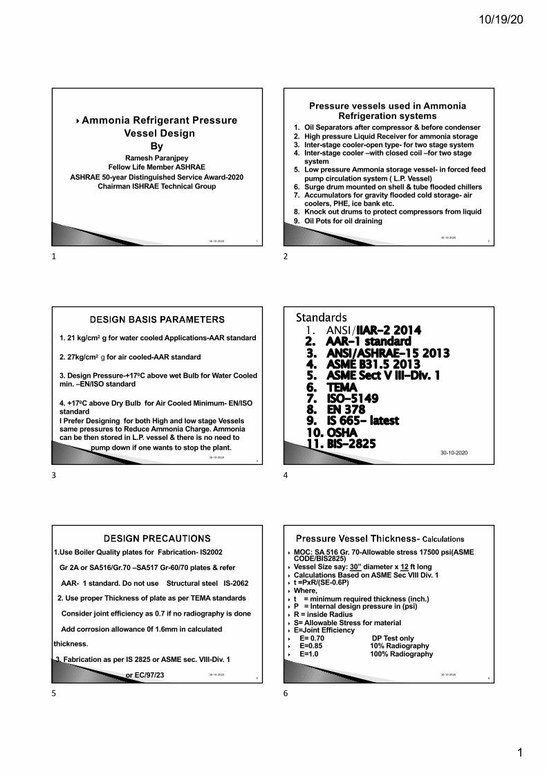
1. Function of oil separator-Ammonia Refrigerant and mineral oils are not miscible with each other.
2. Oil is required primarily for compressor lubrication and oil anywhere else in the system is not desired
3. If oil separator is not efficient, then more oil goes into the system & oil needs to be drained from various other points in the system which is manual process and can lead to problems like accidents.
4. Installing efficient oil separator, even at higher cost, is therefore recommended so that maximum oil is contained in the close loop of compressor and oil separator only
10
30-10-202011
11
OIL SEPARATOR-65 T0 75% Efficiency
30-10-2020
12
10/19/20
3
OIL SEPARATOR SELECTION
Di min. =C x ∅pDi min.= minimum inside shell diameter in mmC=constant-26.6 for single stage and H.P. of two stage C=21.03 for Booster and L.P. Of two stage systems∅p= compressor discharge volume flow rate in m3/hLet us take KC3 compressor with volume as 398CMH at 1000RPM & single stage selectionDi min. =26.6 x 𝟑𝟗𝟖 =26.6x19.93=530mmSelect Type 100 with 600x1397x8mm shell ThicknessFor Booster or two stage KC31=21.03x 𝟑𝟗𝟖=419mmdiaSelect Type 80=419x1039x8mm shell Thickness
30-10-2020
13
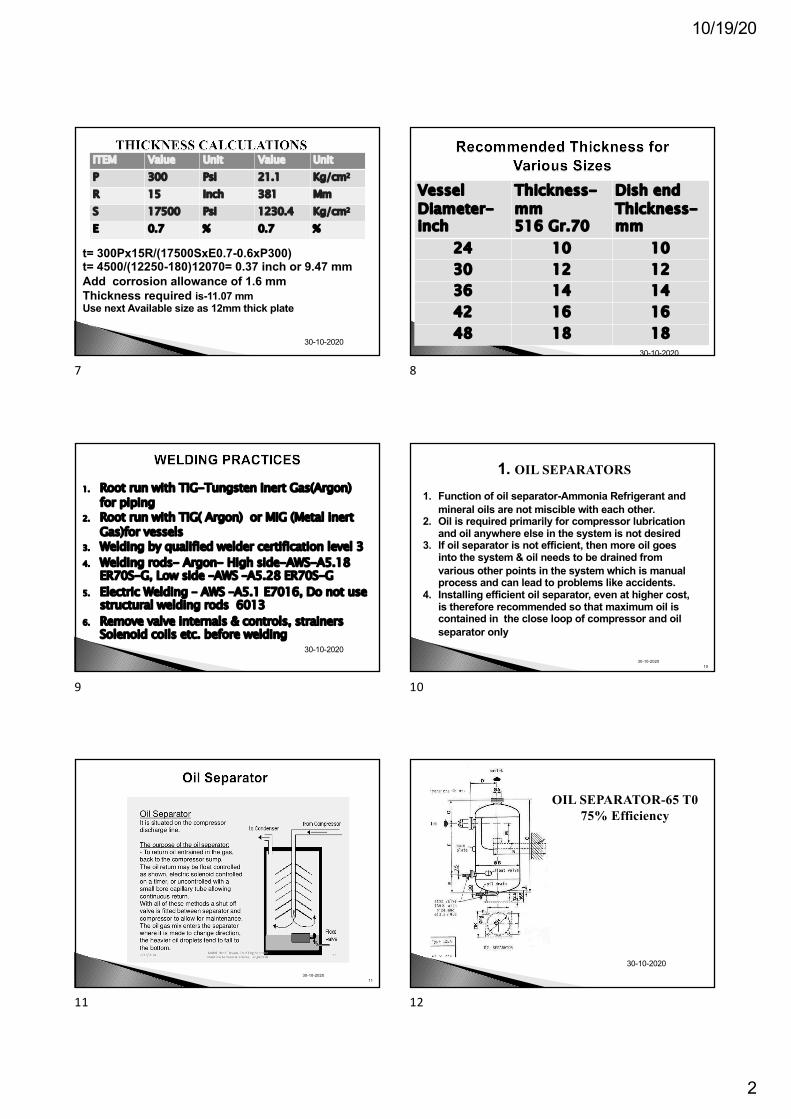
OIL SEPARATOR WITH DEMISTER PAD-85 to 90% Efficiency
30-10-2020
14
30-10-2020
15
30-10-202016
16
30-10-202017
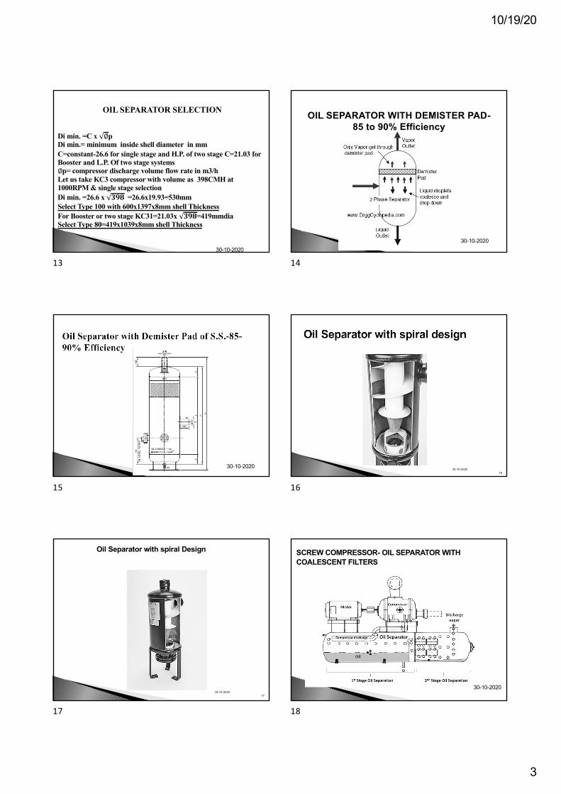
Oil Separator with spiral Design
17
SCREW COMPRESSOR- OIL SEPARATOR WITH COALESCENT FILTERS
30-10-2020
18
10/19/20
4
2. High Pressure ammonia receivers
30-10-2020
19
1.Selection of receiver is done based on the assumption that itshould be able to accommodate entire charge of refrigeration system.
2. This is essential as if one wants to do some repairs, attendleakages, do some piping welding etc. one should be ableto pump ammonia od the entire refrigeration system in this receiver,close the king valve and then carry the modifications/repairs.
3. The receiver should be selected so that when ammonia ispumped down, the level of liquid should be not more than80- 85%. This provides space for liquid to expand as per weatherchanges
4. Many times a standby receiver is provided as per requirement
30-10-202020
20
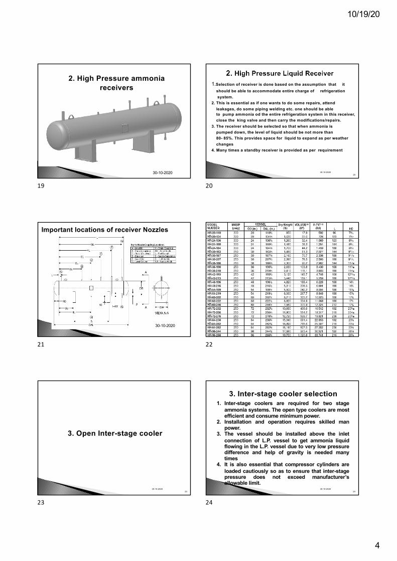
Important locations of receiver Nozzles
30-10-2020
21 22
3. Open Inter-stage cooler
2330-10-2020
23
3. Inter-stage cooler selection
2430-10-2020
1. Inter-stage coolers are required for two stageammonia systems. The open type coolers are mostefficient and consume minimum power.
2. Installation and operation requires skilled manpower.
3. The vessel should be installed above the inletconnection of L.P. vessel to get ammonia liquidflowing in the L.P. vessel due to very low pressuredifference and help of gravity is needed manytimes
4. It is also essential that compressor cylinders areloaded cautiously so as to ensure that inter-stagepressure does not exceed manufacturer’sallowable limit.
24
10/19/20
5
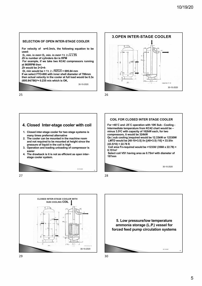
For velocity of w=0.3m/s, the following equation to beused:Di, min. in mm= Di, min. in mm= 1𝟏.𝟐 𝒏 𝒙 𝒁𝒉Zh is number of cylinders &n is RPMFor example, if we take two KC42 compressors runningat 965RPM thenZh would be 2+2=4-Di, min would be = 1𝟏.𝟐 𝟗𝟔𝟓𝒙𝟒 = 695.84 mmIf we select FTO-800 with inner shell diameter of 786mm then actual velocity in the cooler at full load would be 0.3x (695.84/786)2= 0.235 m/s which is OK,
SELECTION OF OPEN INTER-STAGE COOLER
30-10-2020
25
3.OPEN INTER-STAGE COOLER
30-10-2020
26
4. Closed Inter-stage cooler with coil
2730-10-2020
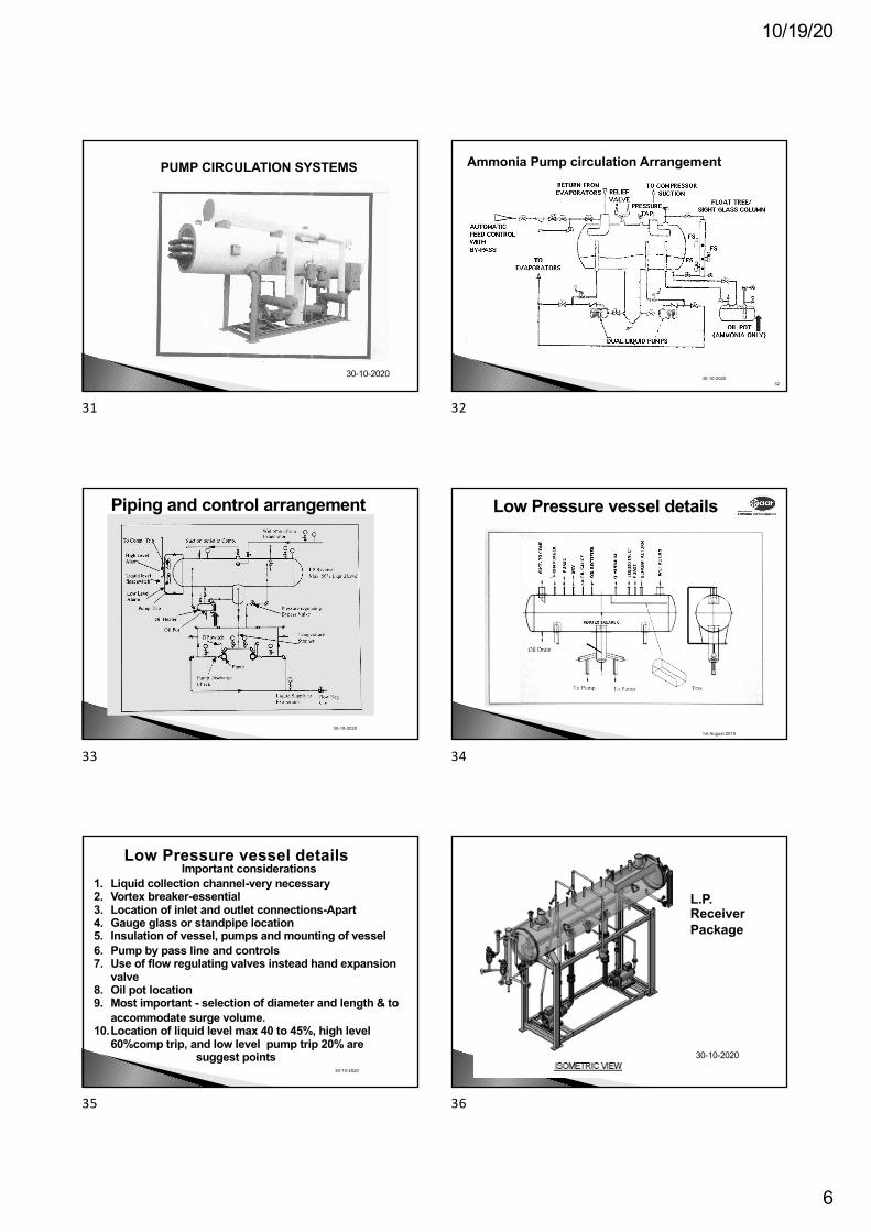
1. Closed inter-stage cooler for two stage systems is many times preferred alternative
2. The cooler can be mounted in the machine room and not required to be mounted at height since the pressure of liquid in the coil is high
3. Operation and loading unloading of compressor is easier
4. The drawback is it is not as efficient as open inter-stage cooler system.
27
For +40˚C and -25˚C operation with 10K Sub - Cooling -Intermediate temperature from KC42 chart would be –minus 3.50C with capacity of 162kW each, for two compressors, it would be 324kWQs ( sub cooling )required would be 12.33kW or 12330WLMTD would be [40-10+3.5] /ln [(40+3.5) /10] = 33.5/ln (43.5/10) = 22.78 KCoil area Fn-required would be =12330/ (3568 x 22.78) = 0.151m2
Select coil VS1 having area as 0.75m2 with diameter of 197mm
COIL FOR CLOSED INTER STAGE COOLER
30-10-2020
28
CLOSED INTER-STAGE COOLER WITH SUB COOLING COIL
30-10-2020
29
5. Low pressure/low temperature ammonia storage (L.P.) vessel for
forced feed pump circulation systems
3030-10-2020
30
10/19/20
6
PUMP CIRCULATION SYSTEMS
30-10-2020
31
30-10-202032
Ammonia Pump circulation Arrangement
32
30-10-2020
Piping and control arrangement
33
1st August 2015
Low Pressure vessel details
34
30-10-2020
Low Pressure vessel detailsImportant considerations
1. Liquid collection channel-very necessary2. Vortex breaker-essential3. Location of inlet and outlet connections-Apart4. Gauge glass or standpipe location5. Insulation of vessel, pumps and mounting of vessel6. Pump by pass line and controls7. Use of flow regulating valves instead hand expansion
valve8. Oil pot location 9. Most important - selection of diameter and length & to
accommodate surge volume.10.Location of liquid level max 40 to 45%, high level
60%comp trip, and low level pump trip 20% are suggest points
35
L.P. Receiver Package
30-10-2020
36
10/19/20
7
6.Surge drum on shell and tube flooded chiller
3730-10-2020
37
30-10-2020
38
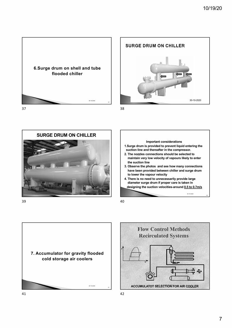
SURGE DRUM ON CHILLER
39
Important considerations1.Surge drum is provided to prevent liquid entering thesuction line and thereafter in the compressor.
2. The nozzles connections should be selected tomaintain very low velocity of vapours likely to enterthe suction line
3. Observe the photos and see how many connectionshave been provided between chiller and surge drumto lower the vapour velocity
4. There is no need to unnecessarily provide largediameter surge drum if proper care is taken indesigning the suction velocities-around 0.5 to 0.7m/s
4030-10-2020
40
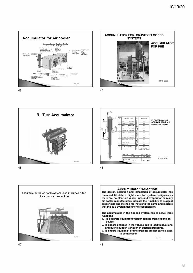
7. Accumulator for gravity flooded cold storage air coolers
4130-10-2020
41
1st August 2015ACCUMULATOT SELECTION FOR AIR COOLER
42
10/19/20
8
30-10-202043
43
ACCUMULATORFOR PHE
ACCUMULATOR FOR GRAVITY FLOODED SYSTEMS
30-10-2020
44
30-10-202045
45
FLOODED Vertical ACCUMULATOR with connection details
30-10-2020
46
30-10-2020
47
47
30-10-202048
The design, selection and installation of accumulator hasremained till date a night mare for system designers asthere are no clear cut guide lines and evaporator or manyair cooler manufacturers indicate their inability to suggestproper size and method for installing the same and indicatethat this is a system designer’s responsibility.
The accumulator in the flooded system has to serve threefunctions1. To separate liquid from vapour coming from expansion
device2. To absorb changes in the volume due to load fluctuations
and due to sudden variation in suction pressures.3. To ensure liquid mist or fine droplets are not carried back
to compressor
48
10/19/20
9
30-10-202049
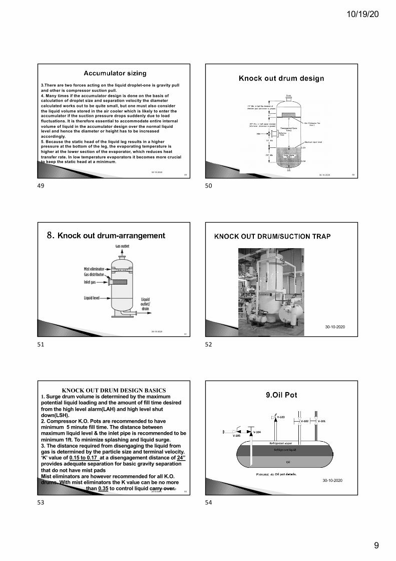
3.There are two forces acting on the liquid droplet-one is gravity pull and other is compressor suction pull.4. Many times if the accumulator design is done on the basis of calculation of droplet size and separation velocity the diameter calculated works out to be quite small, but one must also consider the liquid volume stored in the air cooler which is likely to enter the accumulator if the suction pressure drops suddenly due to load fluctuations. It is therefore essential to accommodate entire internal volume of liquid in the accumulator design over the normal liquid level and hence the diameter or height has to be increased accordingly.5. Because the static head of the liquid leg results in a higher pressure at the bottom of the leg, the evaporating temperature is higher at the lower section of the evaporator, which reduces heat transfer rate. In low temperature evaporators it becomes more crucial to keep the static head at a minimum.
49
30-10-202030-10-202030-10-2020 50
50
30-10-202051
51
30-10-2020
52
19 Jan 2018 AAR ARCON 2018 Delhi 53
KNOCK OUT DRUM DESIGN BASICS1. Surge drum volume is determined by the maximum potential liquid loading and the amount of fill time desired from the high level alarm(LAH) and high level shut down(LSH). 2. Compressor K.O. Pots are recommended to have minimum 5 minute fill time. The distance between maximum liquid level & the inlet pipe is recommended to be minimum 1ft. To minimize splashing and liquid surge.3. The distance required from disengaging the liquid from gas is determined by the particle size and terminal velocity.‘K’ value of 0.15 to 0.17 at a disengagement distance of 24”provides adequate separation for basic gravity separation that do not have mist padsMist eliminators are however recommended for all K.O. drums. With mist eliminators the K value can be no more
than 0.35 to control liquid carry over.
53
30-10-2020
54
10/19/20
10
30-10-202055
5530-10-2020
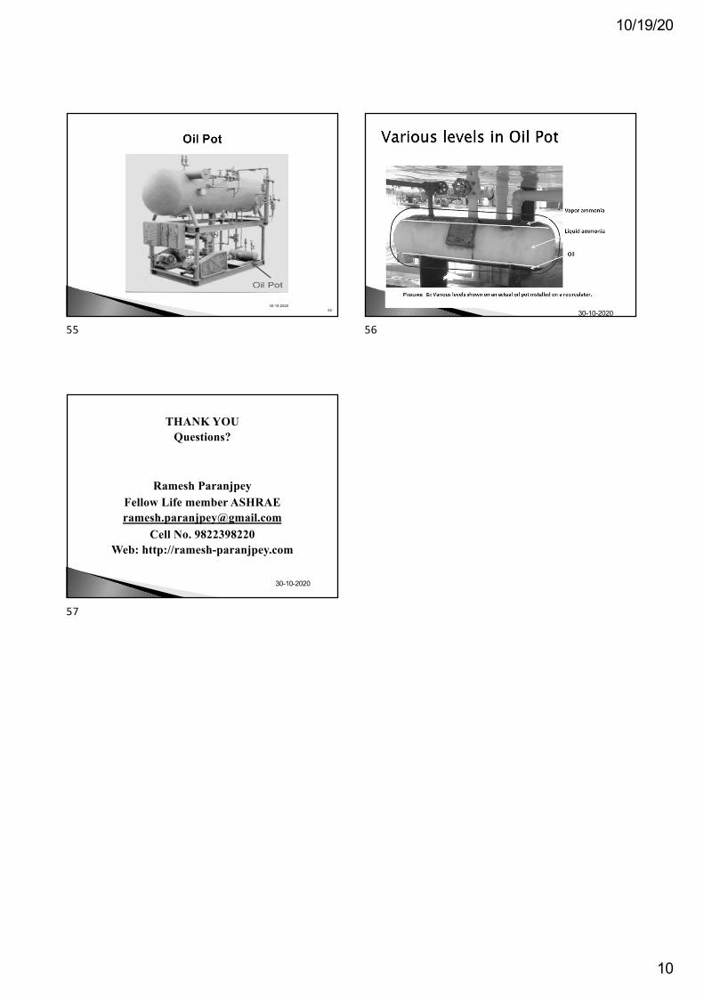
56
THANK YOUQuestions?
Ramesh ParanjpeyFellow Life member [email protected]
Cell No. 9822398220Web: http://ramesh-paranjpey.com
30-10-2020
57

![Presure-Volume-Temperature Properties of H2O-CO2 Fluids (Geophysics) [Short Article] - T. Bowers (1995) WW](https://img.pdfslide.net/doc/110x75/55cf922c550346f57b944a85/presure-volume-temperature-properties-of-h2o-co2-fluids-geophysics-short.jpg)